
automated yield-line analysis software
Version 2.0.b - April 2016
LimitState The Innovation Centre
217 Portobello Sheffield S1 4DP United Kingdom
+44 (0) 114 224 2240 [email protected] www.limitstate.com


1
Summary
Summary
About LimitState:SLAB
LimitState:SLAB identifies in seconds yield-line failure mechanisms that cannot be identified using conventional ultimate limit state analysis software and which might take a lifetime to identify manually. To achieve this, the powerful and efficient numerical analysis procedure ‘Discontinuity Layout Optimization’ (DLO) is used to provide an automatic means of identifying very accurate limit analysis solutions:
An easy to use and generally applicable ultimate limit analysis tool for yield-line analysis and design problems.
No need to pre-determine the likely failure mechanism. Model the problem as it is and the DLO analysis procedure establishes the critical failure mechanism, meaning that it is suitable for a wide range of circumstances, including bridge and building slab analyses involving columns, holes, irregular geometries and boundary conditions.
View and animate the failure mechanism on-screen. Query moments on solid bodies.
Apply partial factors to loading and material strengths. Designed to be used with Eurocodes and other design codes of practice.
System Requirements Component Requirement
Processor Intel or compatible processor (500 MHz or better)
Operating System Windows: XP, Vista, 7, 8, 10. Macintosh: OSX
Hard Drive Space 100 Mb
System RAM 512 Mb
Virtual Memory Minimum 50 Mb configured swap
Other Software Software for viewing PDF documentation (e.g. Adobe Acrobat)
Underlying Technology LimitState:SLAB uses the Discontinuity Layout Optimization (DLO) procedure to obtain solutions.
DLO automatically identifies the critical configuration of yield-lines at failure, which can then be visualized.
The general formulation means that it can be applied to standard and non-standard problems alike.
No need to independently consider different failure modes as all possible modes (anticipated or not anticipated by the engineer) are simultaneously considered, thus significantly reducing the time required to undertake a stability analysis.
The DLO method is underpinned by rigorous theory, published in the leading peer reviewed journal, Proceedings of the Royal Society A.

2
Summary
Modelling Capabilities Wizards for quick generation of standard problem types.
Intuitive GUI allows user defined problems to be rapidly constructed.
Import / export geometries from and to CAD (AutoCAD DXF files).
Quick and simple to modify geometry, boundary conditions, materials and loading.
Multiple load cases can be handled easily, with the critical case always highlighted (no need to manually analyse different potential failure modes).
Directly apply Partial Factors in the analysis, making the software straightforward to use with design codes.
Structural Definitions Define slabs using just moment resistance and self-weight values.
Model orthotropic and isotropic slab strengths.
Partial Factors Specify ‘Favourable’, ‘Neutral’ or ‘Unfavourable’ loading.
Categorise loads as ‘Permanent’, ‘Accidental’ or ‘Variable’.
Apply partial factors based on combinations of each of the above settings.
Apply partial factors to material strength.
Use the inbuilt 'Load Case Manager' to define and solve multiple scenarios in one go.
Output The solution is reported as a factor on load.
Results are based on rigorous and proven limit analysis methods.
Failure mechanisms are represented as yield-lines (a familiar concept to structural engineers).
Animated displacements provide a highly useful visual interpretation of the failure mechanism.
Moments and rotations along yield-lines are displayed both graphically and numerically.
The analysis report output is easily tuned to user preferences.
Interactive Viewer Define, alter and experiment with the model:
Quickly define or modify a model by drawing the geometry directly in the viewer.
Examine or edit object properties using the Property and Geometry editors.
Add to / change structural definitions in a zone using drag and drop functionality.
Switch between different load cases using the tabbed viewer window.
Benefit from a comprehensive context sensitive help system.
Accessibility Many features designed to help the user:
Wizards to allow basic problem types to be rapidly defined and analysed.
Customized reports of the analysis findings can be automatically generated, printed and saved.

3
Summary
Integrated calculator with comprehensive unit conversion functionality.
Validation Underlying technology published in leading peer-reviewed science journal.
Validated against a large, and ever-growing, number of standard test problems (www.limitstate.com/slab/verification).

4
Contents
Summary .............................................................................................................................................................................................................. 1
About LimitState:SLAB ..................................................................................................................................................................................... 1
System Requirements ...................................................................................................................................................................................... 1
Underlying Technology .................................................................................................................................................................................... 1
Modelling Capabilities ..................................................................................................................................................................................... 2
Structural Definitions ....................................................................................................................................................................................... 2
Partial Factors .................................................................................................................................................................................................. 2
Output ............................................................................................................................................................................................................. 2
Interactive Viewer ........................................................................................................................................................................................... 2
Accessibility ..................................................................................................................................................................................................... 2
Validation ......................................................................................................................................................................................................... 3
User Interface .................................................................................................................................................................................................. 6
Property Editor .................................................................................................................................................................................................... 7
Project ............................................................................................................................................................................................................. 8
Structural Definitions ....................................................................................................................................................................................... 8
Flexural ........................................................................................................................................................................................................ 8
Rigid ............................................................................................................................................................................................................. 9
Vertices ............................................................................................................................................................................................................ 9
Internal Boundaries ......................................................................................................................................................................................... 9
External Boundaries ......................................................................................................................................................................................... 9
Solids .............................................................................................................................................................................................................. 10
Nodes ............................................................................................................................................................................................................. 10
Yield-lines....................................................................................................................................................................................................... 10
Blocks ............................................................................................................................................................................................................. 11
Geometry Editor ................................................................................................................................................................................................ 12
Load Case Manager ........................................................................................................................................................................................... 12
Partial Factor Sets .......................................................................................................................................................................................... 12
Calculator ........................................................................................................................................................................................................... 13
Units............................................................................................................................................................................................................... 13
Functions ....................................................................................................................................................................................................... 13
Explorers ............................................................................................................................................................................................................ 14
Vertex, boundary, solid and load explorers ................................................................................................................................................... 14
Structural definition explorer ........................................................................................................................................................................ 14
Viewer Pane ....................................................................................................................................................................................................... 15
Wizards .............................................................................................................................................................................................................. 16
Sample Wizard – Rectangular Slab Project ........................................................................................................................................................ 17
Project Details ................................................................................................................................................................................................ 17
Geometry ....................................................................................................................................................................................................... 17
Structural Definitions ..................................................................................................................................................................................... 18
Loads .............................................................................................................................................................................................................. 19

5
Contents
Load Cases ..................................................................................................................................................................................................... 19
Partial Factors ............................................................................................................................................................................................ 19
Loads .......................................................................................................................................................................................................... 19
Analysis .......................................................................................................................................................................................................... 20
Solve .................................................................................................................................................................................................................. 21
Analysis Details .............................................................................................................................................................................................. 21
Analysis Engine .............................................................................................................................................................................................. 21
Results ........................................................................................................................................................................................................... 21
Report Output.................................................................................................................................................................................................... 22
Report Contents............................................................................................................................................................................................. 23
Menus ................................................................................................................................................................................................................ 24
File ................................................................................................................................................................................................................. 24
Edit ................................................................................................................................................................................................................. 24
Select ............................................................................................................................................................................................................. 25
View ............................................................................................................................................................................................................... 25
View (contd…) ................................................................................................................................................................................................ 26
Draw .............................................................................................................................................................................................................. 26
Tools .............................................................................................................................................................................................................. 27
Analysis .......................................................................................................................................................................................................... 27
Help ............................................................................................................................................................................................................... 28
Dialogs ............................................................................................................................................................................................................... 29
Selection Filter ............................................................................................................................................................................................... 29
Draw Settings ................................................................................................................................................................................................. 29
Create New Structural Definition ................................................................................................................................................................... 30
Project Details ................................................................................................................................................................................................ 31
Preferences .................................................................................................................................................................................................... 31
Preferences (contd…)..................................................................................................................................................................................... 32
Load Case Manager ....................................................................................................................................................................................... 32
Report ............................................................................................................................................................................................................ 33
Toolbars ............................................................................................................................................................................................................. 34
File ................................................................................................................................................................................................................. 34
Edit ................................................................................................................................................................................................................. 34
Cursor ............................................................................................................................................................................................................ 34
Draw .............................................................................................................................................................................................................. 34
Draw (contd…) ............................................................................................................................................................................................... 35
Analysis .......................................................................................................................................................................................................... 35
Animation ...................................................................................................................................................................................................... 35
Zoom .............................................................................................................................................................................................................. 35
Show .............................................................................................................................................................................................................. 35
Show (contd…) ............................................................................................................................................................................................... 36
Select ............................................................................................................................................................................................................. 36
Rotate 3D ....................................................................................................................................................................................................... 36
6
Contents
View 3D .......................................................................................................................................................................................................... 36
View 3D (contd…) .......................................................................................................................................................................................... 37
Loads .............................................................................................................................................................................................................. 37
Help ............................................................................................................................................................................................................... 37
Context Menus .................................................................................................................................................................................................. 38
Toolbars and Property Editor ......................................................................................................................................................................... 38
Viewer Pane (General) ................................................................................................................................................................................... 39
Viewer Pane (Post-Solve Solid) ...................................................................................................................................................................... 40
Structural Definitions Explorer ...................................................................................................................................................................... 40
Other Explorers .............................................................................................................................................................................................. 40
Geometry Editor ............................................................................................................................................................................................ 40
Output Pane ................................................................................................................................................................................................... 40
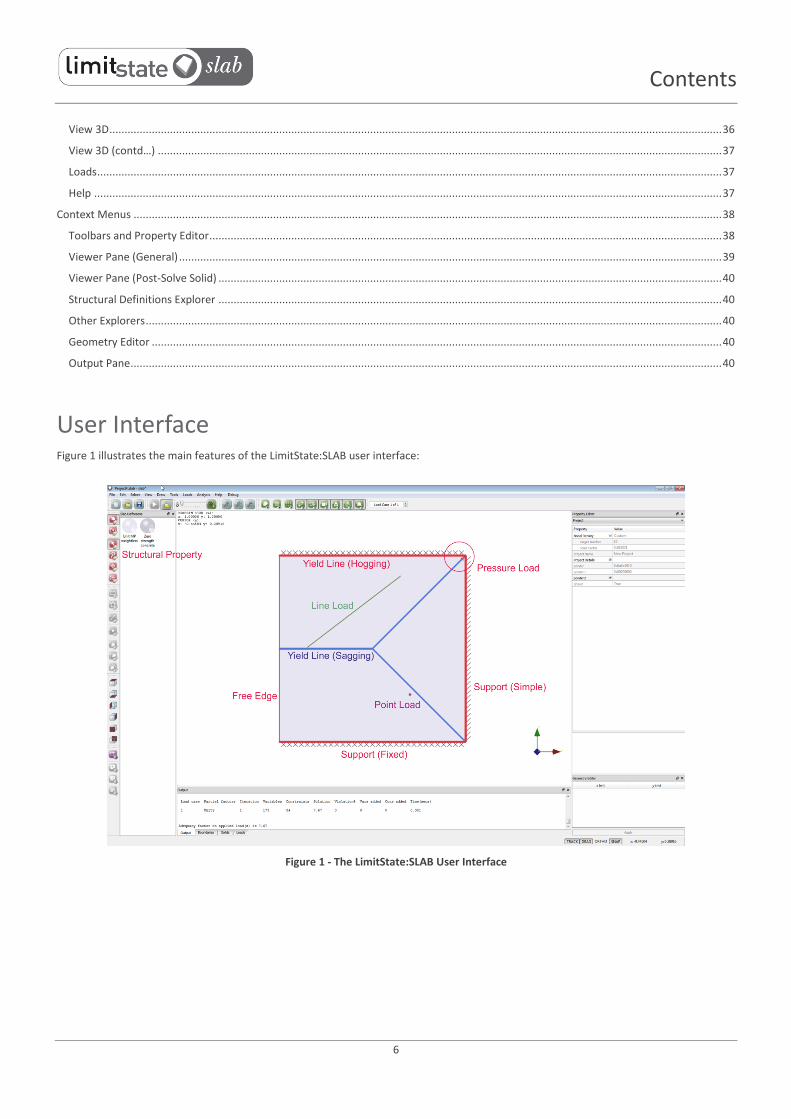
User Interface Figure 1 illustrates the main features of the LimitState:SLAB user interface:
Figure 1 - The LimitState:SLAB User Interface
7
Property Editor
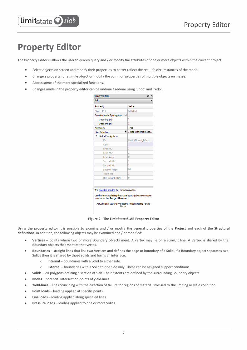
Property Editor The Property Editor is allows the user to quickly query and / or modify the attributes of one or more objects within the current project.
Select objects on screen and modify their properties to better reflect the real-life circumstances of the model.
Change a property for a single object or modify the common properties of multiple objects en masse.
Access some of the more specialized functions.
Changes made in the property editor can be undone / redone using ‘undo’ and ‘redo’.
Figure 2 - The LimitState:SLAB Property Editor
Using the property editor it is possible to examine and / or modify the general properties of the Project and each of the Structural definitions. In addition, the following objects may be examined and / or modified:
Vertices – points where two or more Boundary objects meet. A vertex may lie on a straight line. A Vertex is shared by the Boundary objects that meet at that vertex.
Boundaries – straight lines that link two Vertices and defines the edge or boundary of a Solid. If a Boundary object separates two Solids then it is shared by those solids and forms an interface.
o Internal – boundaries with a Solid to either side.
o External – boundaries with a Solid to one side only. These can be assigned support conditions.
Solids – 2D polygons defining a section of slab. Their extents are defined by the surrounding Boundary objects.
Nodes – potential intersection-points of yield-lines.
Yield-lines – lines coinciding with the direction of failure for regions of material stressed to the limiting or yield condition.
Point loads – loading applied at specific points.
Line loads – loading applied along specified lines.
Pressure loads – loading applied to one or more Solids.

8
Property Editor
The following tables describe, in detail, the properties found in the Property Editor for each of the described features:
Project
Property Description Editable?
Nodal Density Determines how closely nodes are spaced during an analysis by modifying the Target Number. Values can be coarse (250), medium (500), fine (1000), very fine (2000) or custom defined by the user.
Target Number
The total number of nodes that the software will attempt to use when solving the problem. Altering this value will cause the Scale Factor on the Baseline Nodal Spacing to change, thus altering the Actual Nodal Spacing: Actual Nodal Spacing = Baseline Nodal Spacing / Scale Factor Note: The Actual Nodal Spacing is calculated by the software to determine the spacing required to achieve the Target Number of nodes and cannot be directly modified by the user.
Scale Factor A global factor used to scale the spacing between nodes in the project to achieve (or alter) the Target Number of nodes). e.g. doubling the Scale Factor causes the number of nodes used along boundaries to double and the number of nodes used in solids to quadruple.
Project Name A title for the project.
Project Details General information about the project.
Reference Number A reference number.
Location The physical location of the project.
Engineer Name of the engineer responsible.
Organization Name of the organization responsible.
Comments Any additional comments.
Tags Add tags to the file which can be used when searching outside of LimitState:SLAB
Structural Definitions Flexural
Property Description Editable?
Object ID A unique identifier given to all objects in the project.
Color The color of a material as shown in the viewer.
First: Mp+ Sagging moment capacity per unit length, in the direction specified by the angle .
First: Mp- Hogging moment capacity per unit length, in the direction specified by the angle .
First: Angle The angle (anticlockwise) described between the global x axis and the direction in which Mp is acting.
Second: Mp+ Sagging moment capacity per unit length, in the direction specified by the angle .
Second: Mp- Hogging moment capacity per unit length, in the direction specified by the angle .
Second: Angle The angle (anticlockwise) described between the global x axis and the direction in which Mp is acting.
Thickness Thickness of the slab in a particular Solid area. Used in conjunction with the Unit Weight to determine the self-weight of the slab.
Unit weight Unit weight of the slab in a particular Solid area. Used in conjunction with the Thickness to determine the self-weight of the slab.

9
Property Editor
Rigid
Property Description Editable?
Object ID A unique identifier given to all objects in the project.
Color The color of a material as shown in the viewer.
Thickness Thickness of the slab in a particular Solid area. Used in conjunction with the Unit Weight to determine the self-weight of the slab.
Unit weight Unit weight of the slab in a particular Solid area. Used in conjunction with the Thickness to determine the self-weight of the slab.
Vertices
Property Description Editable?
Object ID A unique identifier given to all objects in the project.
x The x coordinate of a vertex. Use Geometry Editor
y The y coordinate of a vertex. Use Geometry Editor
Internal Boundaries
Property Description Editable?
Object ID A unique identifier given to all objects in the project.
Baseline Nodal Spacing The baseline spacing (m) between nodes. Used when calculating the actual spacing between nodes to achieve the Target Number: Actual Nodal Spacing = Baseline Nodal Spacing / Scale Factor.
Structural Definition A list of the materials assigned for use in a boundary.
Support Type The type of support assigned to a Boundary
Free Boundary is able to move and rotate.
Knife-edge The boundary will not move unless ‘lift-off’ is permitted. The overlying slab is considered to be continuous, with moments over the support and rotation around the line of the axis being permitted. A yield-line will form if the hogging moment over the support reaches or surpasses the limiting moment resistance of the slab.
External Boundaries
Property Description Editable?
Object ID A unique identifier given to all objects in the project.
Baseline Nodal Spacing The baseline spacing (m) between nodes. Used when calculating the actual spacing between nodes to achieve the Target Number: Actual Nodal Spacing = Baseline Nodal Spacing / Scale Factor.
Structural Definition The Structural Definition assigned for use in a boundary. Selecting this field brings up a button that opens a dialog allowing a definition to be assigned / removed from a zone.
Support Type The type of support assigned to a Boundary
Fixed Boundary will not move or rotate.
Partially Fixed The boundary is fixed against displacements in all directions. Rotations of the slab around the axis of the boundary are only permitted as a result of yield-line formation at a moment equal to the specified ratio multiplied by the strength of the adjacent slab.
Free Boundary is able to move and rotate.
Symmetry Emulates symmetry boundary conditions.
10
Property Editor
Simple Boundary will rotate but not move (unless ‘lift-off’ is permitted, in which case vertical upwards movement can occur).
Solids
Property Description Editable?
Object ID A unique identifier given to all objects in the project.
Baseline Nodal Spacing The baseline spacing (m) between nodes in a solid. Used when calculating the actual spacing between nodes to achieve the Target Number.
x spacing Baseline Nodal Spacing in the x direction.
y spacing Baseline Nodal Spacing in the y direction.
Structural Definition The Structural Definition assigned for use in a boundary. Selecting this field brings up a button that opens a dialog allowing a definition to be assigned / removed from a zone.
Nodes
Property Description Editable?
x The x coordinate of a node.
y The y coordinate of a node.
z The z coordinate of a node (zero)
Yield-lines
Property Description Editable?
ID A unique identifier given to all objects in the project.
Start Node The node at the start of a yield-line.
x The x coordinate of the point at the start of a yield-line.
y The y coordinate of the point at the start of a yield-line.
z The z coordinate of the point at the start of a yield-line (always zero).
End Node The node at the end of a yield-line.
x The x coordinate of the point at the end of a yield-line.
y The y coordinate of the point at the end of a yield-line.
z The z coordinate of the point at the start of a yield-line (always zero).
Length The Straight-line distance between ‘Start Node’ and ‘End Node’.
Moment The total bending moment acting along the yield-line.
Rotation Instantaneous relative rotation.
11
Property Editor
Blocks Blocks can be selected once the problem is in the solved and in a displaced state.
Property Description Editable?
ID A unique identifier given to all objects in the project.
Point X
ID The identifier of the point.
x The x coordinate of the point.
y The y coordinate of the point.
z The z coordinate of the point.

12
Explorers
Geometry Editor
Figure 3 - The LimitState:SLAB Geometry editor
Examine and / or modify the x and y coordinates of a vertex, boundary or solid
Make rapid alterations to the problem geometry
Load Case Manager
Figure 4 - The LimitState:SLAB Load Case Manager
Define specific combinations of partial factor and loads to be considered during analysis. If multiple load cases are defined, the critical case will be identified automatically during solve.
Partial Factor Sets Specify whether a single or multiple scenario analysis is carried out.
Editable partial factors:
o Neutral loads (permanent, accidental and variable).
o Unfavourable loads (permanent, accidental and variable).
o Favourable loads (permanent, accidental and variable).
o Materials (Mp).
Default available partial factor sets:
o Unity.
Import partial factor sets from .csv file.
Export partial factor sets to .csv file.
Define new partial factor sets.
Delete a partial factor set from a multiple load case problem.

13
Calculator
Use the ‘manage’ dialog to rename or delete individual partial factor sets from the file.
Calculator Quickly calculate values for entry into any field that requires numerical input (simply click in the field and select the calculator
button).
Convert a wide variety of types into the default LimitState:SLAB units:
Figure 5 - The LimitState:SLAB Calculator
Units
Unit Metric Imperial Converter Options
Force / Weight kN lbf N, kN, MN, lbf
Pressure kN/m2 psf (lbf/ft2) kN/m2, MN/m2, lbf/ft2, lbf/yd2
Unit weight kN/m3 pcf (lbf/ft3) kN/m3, MN/m3, lbf/ft3, lbf/yd3
Length m ft mm , cm , m, ft, yd
Area m2 ft2 mm2 , cm2 , m2, ft2, yd2
Volume m3 ft3 mm3 , cm3 , m3, ft3, yd3
Functions +, -, *, / - add, subtract, multiply, divide
sqrt - square root
x2 - square
sin, cos, tan - trigonometric functions
abs - absolute
ln - natural logarithm
(x) - parenthesis
^ - exponent
pi - 3.14159
MS – store in memory
MR – recall memory
MC – clear memory
M+ - add to number in memory

14
Viewer Pane
Explorers
Vertex, boundary, solid and load explorers
When the project is unlocked, objects selected in the Vertex, Boundary, Solid and Load explorers are highlighted in the viewer pane (and vice versa).
The Vertex Explorer displays the Object ID.
The Boundary Explorer displays the Object ID and Support Type.
The Solid Explorer displays the Object ID.
The Load Explorer displays the Name, Pattern, Value, Units and Load Type.
Figure 6 - The LimitState:SLAB Solid Explorer
Figure 7 - The LimitState:SLAB Boundary Explorer
Structural definition explorer Drag and drop from the Structural Definition Explorer to assign ‘materials’ to boundaries and solids.
Create user-defined structural definitions, with full control over properties for each type (see the Dialogs section).
Import pre-defined structural definitions from file.
Export user-defined structural definitions to file.
Figure 8 - The LimitState:SLAB Structural Definition Explorer
The Material Explorer contains a library of built-in structural definitions of different types (metric defaults shown):

15
Viewer Pane
Name
Firs
t: M
p+
(kN
m/m
)
Firs
t: M
p-
(kN
m/m
)
Firs
t: A
ngl
e
Seco
nd
: M
p+
(kN
m/m
)
Seco
nd
: M
p-
(kN
m/m
)
Seco
nd
: A
ngl
e
Thic
knes
s (m
)
Un
it W
eig
ht
(kN
/m3 )
Unit MP weightness
1 1 0 1 1 90 0.25 0
Zero strength concrete
0 0 0 0 0 90 0.25 0
Unit MP concrete
1 1 0 1 1 90 0.25 24
Rigid weightless
- - - - - - 0.25 0
Viewer Pane A fully interactive graphical modelling environment.
Total freedom to define or modify problem geometries.
View the model from any angle (including in 3D) and zoom into areas of interest.
Select any part of the model with the mouse to view or modify its properties.
Figure 9 - The LimitState:SLAB Modelling Environment
16
Wizards
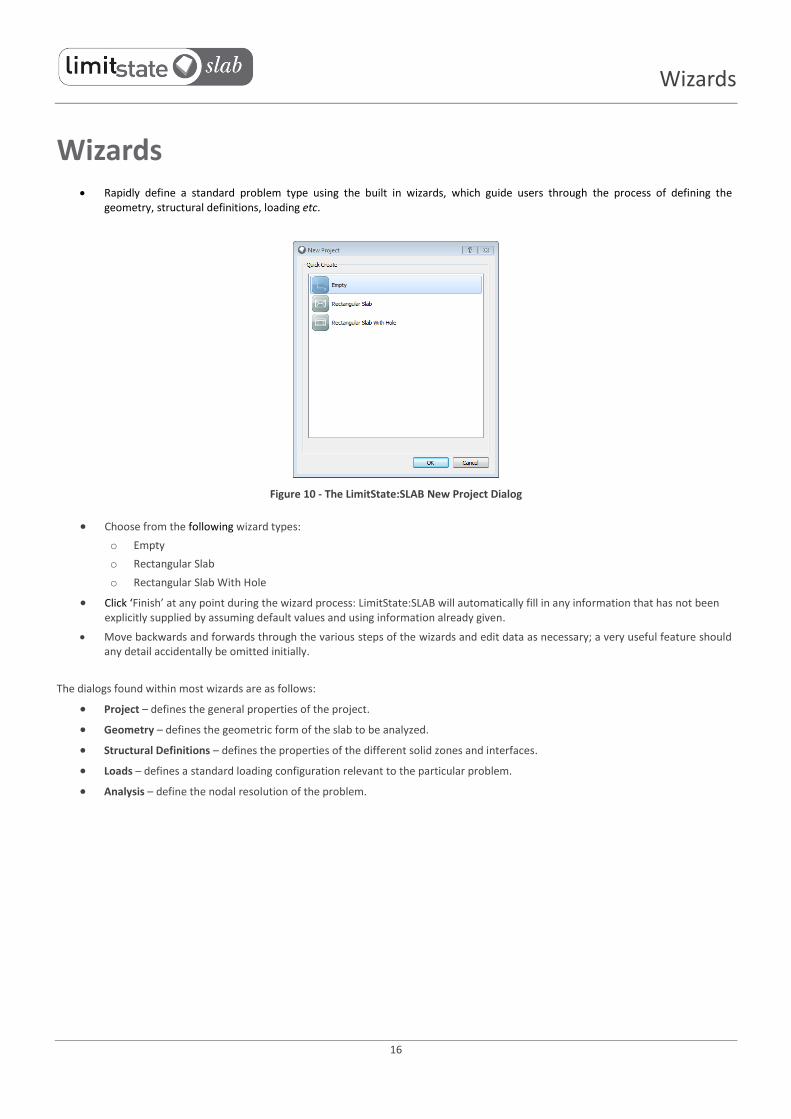
Wizards Rapidly define a standard problem type using the built in wizards, which guide users through the process of defining the
geometry, structural definitions, loading etc.
Figure 10 - The LimitState:SLAB New Project Dialog
Choose from the following wizard types:
o Empty
o Rectangular Slab
o Rectangular Slab With Hole
Click ‘Finish’ at any point during the wizard process: LimitState:SLAB will automatically fill in any information that has not been explicitly supplied by assuming default values and using information already given.
Move backwards and forwards through the various steps of the wizards and edit data as necessary; a very useful feature should any detail accidentally be omitted initially.
The dialogs found within most wizards are as follows:
Project – defines the general properties of the project.
Geometry – defines the geometric form of the slab to be analyzed.
Structural Definitions – defines the properties of the different solid zones and interfaces.
Loads – defines a standard loading configuration relevant to the particular problem.
Analysis – define the nodal resolution of the problem.

17
Sample Wizard
Sample Wizard – Rectangular Slab Project Some of the dialogs shown in other wizards will be different to those shown here (e.g. those relating to geometry). This example
wizard is however indicative of the different wizards available in LimitState:SLAB.
In all wizard dialogs, default data is assumed unless otherwise specified by the user.
Project Details
Figure 11 - The LimitState:SLAB Rectangular Slab Project ‘Project Details’ Dialog
Deals with ‘general’ aspects of the model
All of the details that can be specified here are optional:
o Project Name
o Reference number
o Location
o Engineer name
o Organization
o Comments
o Tags
Geometry Define the key dimensions of the footing (the figure in the dialog clearly indicates the meaning of the parameters to be entered):
o Slab dimensions
o Skew angle
o Boundary conditions

18
Sample Wizard
Figure 12 - The LimitState:SLAB Rectangular Slab Project ‘Geometry’ Dialog
Structural Definitions
Figure 13 - The LimitState:SLAB Rectangular Slab Project ‘Structural Definitions’ Dialog
Define the ‘material’ properties of the slab:
Create new structural definition:
o Attributes – Name
o Attributes – Color
o Properties – First direction: Mp+
o Properties – First direction: Mp-
o Properties – First direction: Angle (degrees)
o Properties – Second direction: Mp+
o Properties – Second direction: Mp-
o Properties – Second direction: Angle (degrees)
o Properties – Thickness

19
Sample Wizard
o Properties – Unit weight
Use existing structural definition
Loads Define the vertical load applied to the slab:
Figure 14 - The LimitState:SLAB Rectangular Slab Project ‘Loads’ Dialog
Load Cases Define the different load cases to be considered during analysis:
Partial Factors
Specify whether a single or multiple load case analysis is carried out.
Editable partial factors:
o Neutral loads (permanent, accidental and variable).
o Unfavourable loads (permanent, accidental and variable).
o Favourable loads (permanent, accidental and variable).
o Materials (Mp).
Default available partial factor sets:
o Unity.
Import partial factor sets from .csv file.
Export partial factor sets to .csv file.
Define new partial factor sets.
Delete a partial factor set from a multiple load case problem.
Loads
Define or delete loads in the Loads Database:
o Self-weight
o Point loads
o Line loads
o Pressure loads
o All loads can be assigned Permanent, Accidental or Variable status.
20
Sample Wizard
Assign loads:
o To Solids (Pressure, Self-weight)
o Between two Vertices (Line)
o At a Vertex (Point)
Figure 15 - The LimitState:SLAB Loads Database Dialog
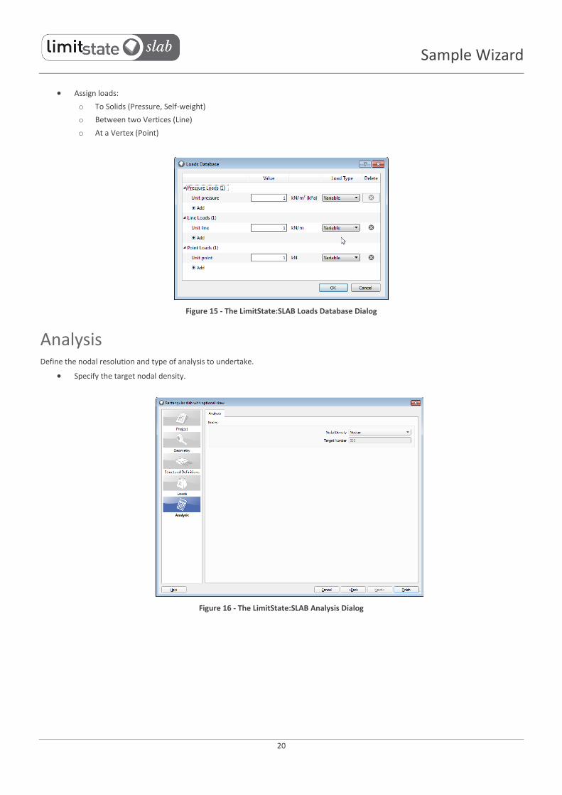
Analysis Define the nodal resolution and type of analysis to undertake.
Specify the target nodal density.
Figure 16 - The LimitState:SLAB Analysis Dialog
21
Sample Wizard
Solve
Analysis Details Performs a kinematic or ‘mechanism’ analysis based on plasticity theory, and assuming small displacements.
Provides a solution in terms of an adequacy factor on loads.
For a Project with a several load cases, the adequacy factor for each is computed and the lowest (most critical) is identified.
Analysis Engine Uses MOSEK, a powerful interior point linear programming solver (see www.mosek.com).
For maximum efficiency all problem data is passed to the solver via memory.
More detailed information on the progress towards a solution is available in the Preferences dialog.
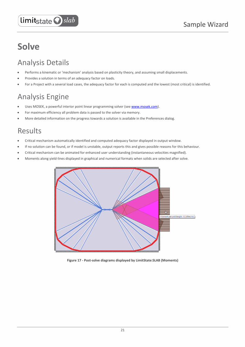
Results Critical mechanism automatically identified and computed adequacy factor displayed in output window.
If no solution can be found, or if model is unstable, output reports this and gives possible reasons for this behaviour.
Critical mechanism can be animated for enhanced user understanding (instantaneous velocities magnified).
Moments along yield-lines displayed in graphical and numerical formats when solids are selected after solve.
Figure 17 - Post-solve diagrams displayed by LimitState:SLAB (Moments)

22
Solve
Report Output
Figure 18 - The LimitState:SLAB Report View
Chose the sections that are included in the report:
o About
o Summary
o Geometry
o Structural Definitions
o Partial Factors
o Loads
o Load Cases
Customize the document with user-defined headers and footers.
Print the report directly from LimitState:SLAB or save the file in RTF format.
23
Menus
Report Contents By default, each report contains all the sections mentioned above, containing the following details:
Section Contents
About A paragraph of text outlining the method of analysis (DLO) used by
LimitState:SLAB
Summary
Name
Reference No.
Location
Name of engineer
Organization
Date of analysis
Comments
Tags
Target nodal density
Nodal spacing scale factor
Analysis result: o Critical load case o Partial factor set o Analysis type o Adequacy factor o The critical load case is identified and a graphical
representation of the critical failure mechanism is shown
Geometry
Global o Number of vertices o Number of boundaries o Number of solids
Boundary objects o ID o Start vertex ID o End vertex ID o Baseline nodal spacing o Support type o Structural Definition(s)
Solid objects o ID (any solids with loads applied are highlighted by an *) o Vertex IDs o Boundary IDs o Baseline nodal spacing (x / y) o Structural Definition(s)
Structural Definitions
All properties associated with the structural definitions used in the model:
Flexural: o Icon o Name o Thickness o Unit weight o First: Mp
+
o First: Mp-
o First: Angle o Second: Mp
+ o Second: Mp
- o Second: Angle
Rigid: o Icon o Name o Thickness o Unit weight
Partial factors
For each load case: o Neutral: permanent o Neutral: variable o Neutral: accidental o Unfavourable: permanent o Unfavourable: variable o Unfavourable: accidental o Favourable: permanent o Favourable: variable o Favourable: accidental o Mp
The partial factor set used in the critical scenario is also identified.
Loads
Loaded object ID
Value
Units
Type of load
Load Cases
For each load case: o Name o Action Type o Position o Adequacy (true/false)

24
Solve
Menus
File
Figure 19 - The LimitState:SLAB File Menu
Action Result
New... Start a new project from scratch.
Open... Open a previously saved project.
Close Close the current project.
Save Save the current project using the current filename.
Save As... Save the current project under a different filename.
Import... Import predefined Structural Definitions (.csv) or problem Geometry (.dxf).
Export... Export problem Structural Definitions (.csv), Geometry (.dxf, .eps or .asy), an Image (.png, .jpg, .tiff, .eps or .ps) or Animation (.avi or .gif).
Recent Files Open a recently saved project.
Exit Exit LimitState:SLAB.
Edit
Figure 20 - The LimitState:SLAB Edit Menu
Action Result
Undo Undo the last action.
Redo Redo the last undo.
Delete Delete the currently selected object(s).

25
Menus
Select
Figure 21 - The LimitState:SLAB Select Menu
Action Result
Click Select objects by clicking them with the mouse pointer.
Rectangle Select objects by drawing a rectangle around them.
Filter...
Select only objects of a particular type (or types): o Vertex
o Boundary
o Solid
o Yield-line
o All
View
Figure 22 - The LimitState:SLAB View Menu
Action Result
Zoom
Zoom towards or away from the model:
o Zoom All (Display the entire model)
o Zoom In (Zoom towards the centre of the model)
o Zoom Out (Zoom away from the centre of the model)
Property Editor Toggle the display of the Property Editor.
Geometry Editor Toggle the display of the Geometry Editor.
Output Toggle the display of the Output pane.

26
Solve
View (contd…)
Action Result
Explorers
Toggle the display of the Explorers:
o Vertex
o Boundary
o Solid
o Structural Definitions
o Loads
Toolbars
Toggle the display of the Toolbars:
o File
o Edit
o Cursor
o Draw
o Loads
o Rotate 3D
o Analysis
o Animation
o Zoom
o Show
o View 3D
o Help
3D View
View the model from various 3D viewpoints:
o Top
o Bottom
o Left
o Right
o Front (Default)
o Back
o Show Global Axis
o Toggle Perspective
Show Grid Toggle the display of the Grid.
Show Nodes Toggle the display of the Nodes.
Show Supports Toggle the display of the Supports.
Show Boundaries Toggle the display of the Boundaries.
Show Solids Toggle the display of the Solid objects.
Show Loads Toggle the display of the Loads.
Show Yield-lines Toggle the display of the Yield-lines.
Show Post-Solve Diagrams Toggle the display of post-solve ‘on solve’ diagrams.
Draw
Figure 23 - The LimitState:SLAB Draw Menu

27
Menus
Action Result
Construction Line
Draw a construction line on the viewer pane (these are to aid in the generation of the model and are not counted during analysis):
o Vertical / Horizontal / Custom / Clear All
Solid
Draw a solid object:
o Rectangle (a 4 sided solid defined by two corners)
o Polygon (a multi-sided solid defined by all of its corners)
Line Draw a line using two points.
Vertex Add a vertex to a line.
Settings... Open the draw settings dialog.
Tools
Figure 24 - The LimitState:SLAB Tools Menu
Action Result
Create New Structural Definition...
Open the Create New Structural Definition dialog.
Project Details... Open the Project Details dialog.
Preferences... Open the Preferences dialog.
Analysis
Figure 25 - The LimitState:SLAB Analysis Menu
Action Result
Preview Nodes Display the nodes that will be used during analysis (these are the potential end-points of yield-lines).
Diagnostics Open the Diagnostics dialog to display information, warnings and errors associated with the problem.
Solve Analyse the problem.
Unlock Allow the problem to be edited following an analysis or previewing of the nodes.
Play Animation Animate the failure mechanism for the selected load case.
Report... Generate a report following analysis.

28
Solve
Help
Figure 26 - The LimitState:SLAB Help Menu
Action Result
Help Open the LimitState:SLAB help system.
Update Check for (and download) updates for LimitState:SLAB.
License Information View information about the current license being used and swap to a different license if required.
About Display information regarding the version of LimitState:SLAB currently being used.

29
Dialogs
Dialogs Aside from standard Save / Open / Import / Export dialogs, the following dialogs are available in LimitState:SLAB:
Selection Filter Accessed from the Select menu.
Set which object types can be selected in the viewer pane:
Figure 27 - The LimitState:SLAB Selection Filter Dialog
Draw Settings Accessed from the Draw menu.
Specify grid dimensions and snap settings:
Figure 28 - The LimitState:SLAB Draw Settings Dialog

30
Dialogs
Grid / Snap Option Description
Grid Extents : Auto calculate extents Adaptively resize the drawing extents during modelling.
Extents : Minimum x Specify an initial minimum coordinate along the x axis.
Extents : Minimum y Specify an initial minimum extent along the y axis.
Extents : Maximum x Specify an initial maximum extent along the x axis.
Extents : Maximum y Specify an initial maximum extent along the y axis.
Major gridlines: x spacing Specify the spacing between major x axis gridlines.
Major gridlines: y spacing Specify the spacing between major y axis gridlines.
Minor gridlines: x intervals Specify the number of intervals between major x axis gridlines.
Minor gridlines: y intervals Specify the number of intervals between major y axis gridlines.
Snap Snap Marker Size Increase or decrease the size of the snap marker as displayed in the viewer.
Snap Sensitivity Increase or decrease the required distance between the cursor and a feature before a snap marker is displayed.
Point Snap to Points.
Perpendicular When drawing a line or polygon, snap to a point on an existing line that forms a right angle between that and the line being drawn.
Line Snap to Line objects.
Grid Snap to the Grid intersection points.
Intersection Snap to Intersections between line objects.
Create New Structural Definition Accessed from the Tools menu.
Define a new structural definition of any of the standard types:
Type User-Defined Variables
Flexural
Icon
Name
Thickness
Unit weight
First: Mp+
First: Mp-
First: Angle
Second: Mp+
Second: Mp-
Second: Angle
Rigid
Icon
Name
Thickness
Unit weight
31
Dialogs
Project Details Accessed from the Tools menu.
Specify general details about the current project:
Type User-Defined Variables
Details
Project Name
Reference No
Location
Engineer Name
Organization
Comments and Tags
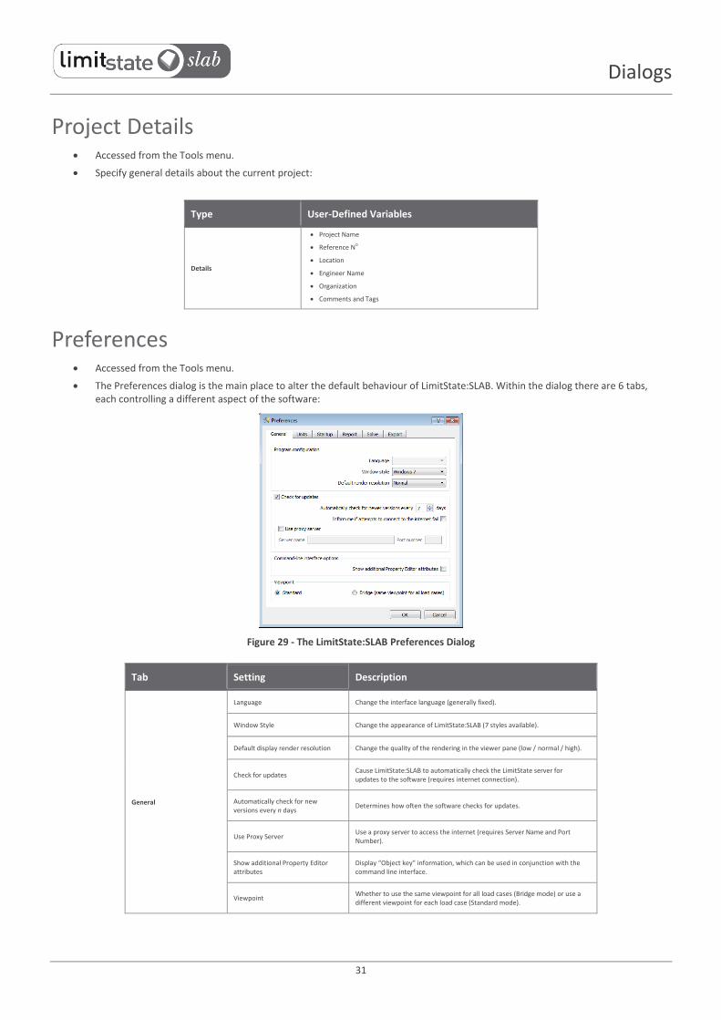
Preferences Accessed from the Tools menu.
The Preferences dialog is the main place to alter the default behaviour of LimitState:SLAB. Within the dialog there are 6 tabs, each controlling a different aspect of the software:
Figure 29 - The LimitState:SLAB Preferences Dialog
Tab Setting Description
General
Language Change the interface language (generally fixed).
Window Style Change the appearance of LimitState:SLAB (7 styles available).
Default display render resolution Change the quality of the rendering in the viewer pane (low / normal / high).
Check for updates Cause LimitState:SLAB to automatically check the LimitState server for updates to the software (requires internet connection).
Automatically check for new versions every n days
Determines how often the software checks for updates.
Use Proxy Server Use a proxy server to access the internet (requires Server Name and Port Number).
Show additional Property Editor attributes
Display “Object key” information, which can be used in conjunction with the command line interface.
Viewpoint Whether to use the same viewpoint for all load cases (Bridge mode) or use a different viewpoint for each load case (Standard mode).

32
Dialogs
Preferences (contd…)
Tab Setting Description
Units
Metric Use metric units (kN, m etc.) in the project.
Imperial Use imperial units (lb, ft etc.) in the project. Also option to use defaults tailored for Imperial Units (in Wizards and built-in materials).
Startup
Show ‘ Welcome’ dialog next time Display the welcome dialog the next time the software is started.
Show analysis tip after wizards completed
Display the analysis tip each time a wizard is completed.
Clear recent files list Clear the list of recently accessed files.
Report
Header image Change the default report header image for one of your own choice (requires png format image).
Footer image Change the default report footer image for one of your own choice (requires png format image).
Solve
Display detailed information in output window
Cause the output window to display detailed information about the analysis:
Load Case *
Partial factors *
Iteration
Variables
Constraints
Solution *
Violation%
Variables added
Constraints added
Time (sec) * Shown by default
Number of significant figures to display in the answer
Increase or decrease the precision of the answer.
Animate after solve for problems with less than 1000 nodes
Automatically animate the solution if the problem contains less than 1000 nodes.
Animate if no more than X nodes Automatically animate the solution after solve if the target number of nodes is less than X.
Do not animate after solve Do not animate the failure mechanism after a solution is found.
Export Width (pixels) Change the width of exported images and animations.
Load Case Manager Define the loads and partial factor sets to be considered during analysis:
Figure 30 - The LimitState:SLAB Load Case Manager Dialog

33
Dialogs
Option Option Description
Editable partial factors
Unfavourable loads Define partial factors (multipliers) for unfavourable permanent, accidental and variable loads.
Favourable loads Define partial factors (multipliers) for favourable permanent, accidental and variable loads.
Neutral loads Define partial factors (multipliers) for neutral permanent, accidental and variable loads.
Materials Define partial factors (divisors) for Mp
Predefined partial factors Unity All partial factors set to 1.0
Other options
{Import...} Import partial factor sets from .csv file.
{Export...} Export partial factor sets to .csv file.
<New...> Define new partial factor sets.
<Delete...> Delete a partial factor set.
Report Chose the sections that are included in the report:
Figure 31 - The LimitState:SLAB Report Options Dialog
34
Toolbars
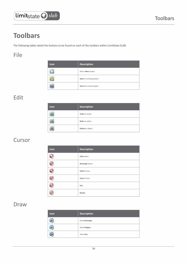
Toolbars The following tables detail the buttons to be found on each of the toolbars within LimitState:SLAB:
File
Icon Description
Start a New project.
Open an existing project.
Save the current project.
Edit
Icon Description
Undo an action.
Redo an action.
Delete an object.
Cursor
Icon Description
Click Select.
Rectangle Select.
Select Cursor.
Zoom Cursor.
Pan.
Rotate.
Draw
Icon Description
Draw Rectangle.
Draw Polygon.
Draw Line.

35
Toolbars
Draw (contd…)
Icon Description
Draw Vertex.
Draw Horizontal construction line.
Draw Vertical construction line.
Draw Angled construction line.
Analysis
Icon Description
Solve.
Change Analysis type.
Lock / Unlock.
Animation
Icon Description
Play animation.
Magnify displacements.
Zoom
Icon Description
Zoom All.
Zoom In.
Zoom Out.
Show
Icon Description
Show Construction lines.
Show the Grid.

36
Toolbars
Show (contd…)
Icon Description
Show Nodes.
Show Supports.
Show Boundaries.
Show Solids.
Show Loads.
Show Yield-lines.
Show Post-solve diagrams.
View in 3D mode.
Select
Icon Description
Select a Single object.
Select objects using a Rectangle.
Rotate 3D
Icon Description
Rotate around the x axis.
Rotate around the y axis.
Rotate around the z axis.
Rotate 3D.
View 3D
Icon Description
View from the Top.
View from the Bottom.
View from the Left.

37
Toolbars
View 3D (contd…)
Icon Description
View from the Right.
View from the Back.
View from the Front.
Loads
Icon Description
Open the Load Case Manager dialog.
Insert a Point Load.
Insert a Line Load.
Insert a Pressure Load.
Help
Icon Description
Help.
Information.

38
Context Menus
Context Menus The following details the context menus to be found when right-clicking the mouse in various areas of the LimitState:SLAB user interface:
Toolbars and Property Editor Toggle the display of various GUI objects:
Option Description
Vertex Explorer Toggle the display of the Vertex explorer.
Boundary Explorer Toggle the display of the Boundary explorer.
Solid Explorer Toggle the display of the Solid explorer.
Structural Definitions Explorer Toggle the display of the Structural Definitions explorer.
Property Editor Toggle the display of the Property editor.
Geometry Editor Toggle the display of the Geometry editor.
Output Toggle the display of the Output pane.
Toggle the display of various toolbars:
Option Description
File Toggle the display of the File toolbar.
Edit Toggle the display of the Edit toolbar.
Cursor Toggle the display of the Cursor toolbar.
Option Description
Draw Toggle the display of the Draw toolbar.
Rotate 3D Toggle the display of the Rotate 3D toolbar.
Analysis Toggle the display of the Analysis toolbar.
Animation Toggle the display of the Animation toolbar.
Zoom Toggle the display of the Zoom toolbar.
Show Toggle the display of the Show toolbar.
View 3D Toggle the display of the View 3D toolbar.
Help Toggle the display of the Help toolbar.

39
Context Menus
Viewer Pane (General)
Option Description
Exit Exit the context menu.
Select Change the cursor to select objects.
Click Select objects by clicking on them.
Rectangle Select objects by drawing a rectangle around them.
Pan Change the cursor to allow panning of the model in the viewer pane.
Rotate Change the cursor to allow rotation of the model in the viewer pane.
Rotate 3D Rotate the model around all 3 main Cartesian axes.
Rotate About x Rotate the model around the x axis.
Rotate About y Rotate the model around the y axis.
Rotate About z Rotate the model around the z axis.
Zoom Change the cursor to allow zooming into and out of the viewer pane.
Zoom In Zoom into the image by 1 increment.
Zoom Out Zoom out of the image by 1 increment.
Zoom All Zoom out to the extents of the problem.
View Change the view of the model.
Top View the model from the top.
Bottom View the model from the bottom.
Right View the model from the right.
Left View the model from the left.
Front View the model from the front.
Back View the model from the back.
View 3D View the model in 3D.
Zoom All Zoom out to the extents of the problem.
Show Global Axis Toggle the display of the global axis.
Perspective Toggle perspective view (needs to be in conjunction with 3D view).
Render
High View the model at high quality (maximum antialiasing).
High Resolution Wireframe View the model as a high resolution wireframe.
Normal View the model at normal quality (moderate antialiasing).
Wireframe View the model as a wireframe.
Low Resolution View the model in low resolution (minimal antialiasing).
Low Resolution Wireframe View the model as a low resolution wireframe.
Save Image Save the current view of the model as a png, jpg, tiff, eps or ps image.

40
Context Menus
Viewer Pane (Post-Solve Solid)
Option Description
Moment View moment diagrams for selected solids.
Structural Definitions Explorer
Option Description
Delete User Defined Structural Definition
Delete the selected structural definition.
Duplicate Structural Definition Copy all the properties of the selected structural definition to a new structural definition.
New Structural Definition... Create a new structural definition from scratch.
Export Structural Definitions... Save the current structural definitions library as a csv file.
Import Structural Definition... Import a pre-saved csv structural definitions library into LimitState:SLAB.
Other Explorers
Option Description
Copy Details Copy all the properties of the selected object.
Paste Details Paste all the properties of a previously copied object.
Copy Copy the current cell.
Paste Paste the properties of a previously copied cell.
Select All Select all cells in the table.
Deselect All Deselect all selected cells.
Geometry Editor
Option Description
Copy Copy the current cell.
Paste Paste the properties of a previously copied cell.
Output Pane
Option Description
Copy Copy the currently highlighted text.
Select All Select all text.
Clear All Clear all text.

41
Context Menus

LimitState Ltd The Innovation Centre
217 Portobello Sheffield
S1 4DP UK
+44 (0) 114 224 2240 [email protected] www.limitstate.com


