
Ausgabe/Edition: 06/2016

I | Inhaltsverzeichnis Contents
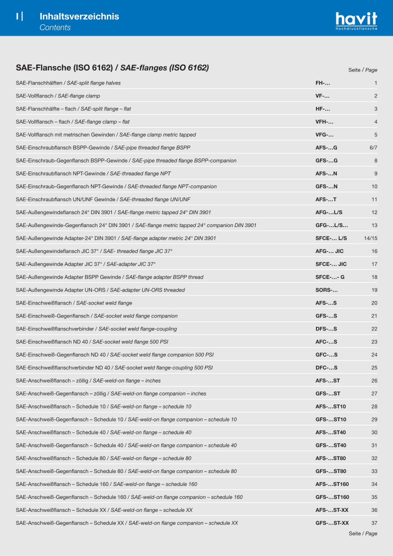
SAE-Flansche (ISO 6162) / SAE-flanges (ISO 6162) Seite / Page
SAE-Flanschhälften / SAE-split flange halves FH-… 1
SAE-Vollflansch / SAE-flange clamp VF-… 2
SAE-Flanschhälfte – flach / SAE-split flange – flat HF-… 3
SAE-Vollflansch – flach / SAE-flange clamp – flat VFH-… 4
SAE-Vollflansch mit metrischen Gewinden / SAE-flange clamp metric tapped VFG-… 5
SAE-Einschraubflansch BSPP-Gewinde / SAE-pipe threaded flange BSPP AFS-…G 6/7
SAE-Einschraub-Gegenflansch BSPP-Gewinde / SAE-pipe threaded flange BSPP-companion GFS-…G 8
SAE-Einschraubflansch NPT-Gewinde / SAE-threaded flange NPT AFS-…N 9
SAE-Einschraub-Gegenflansch NPT-Gewinde / SAE-threaded flange NPT-companion GFS-…N 10
SAE-Einschraubflansch UN/UNF Gewinde / SAE-threaded flange UN/UNF AFS-…T 11
SAE-Außengewindeflansch 24° DIN 3901 / SAE-flange metric tapped 24° DIN 3901 AFG-…L/S 12
SAE-Außengewinde-Gegenflansch 24° DIN 3901 / SAE-flange metric tapped 24° companion DIN 3901 GFG-…L/S… 13
SAE-Außengewinde Adapter-24° DIN 3901 / SAE-flange adapter metric 24° DIN 3901 SFCE-… L/S 14/15
SAE-Außengewindeflansch JIC 37° / SAE- threaded flange JIC 37° AFG-… JIC 16
SAE-Außengewinde Adapter JIC 37° / SAE-adapter JIC 37° SFCE-… JIC 17
SAE-Außengewinde Adapter BSPP Gewinde / SAE-flange adapter BSPP thread SFCE-…- G 18
SAE-Außengewinde Adapter UN-ORS / SAE-adapter UN-ORS threaded SORS-… 19
SAE-Einschweißflansch / SAE-socket weld flange AFS-…S 20
SAE-Einschweiß-Gegenflansch / SAE-socket weld flange companion GFS-…S 21
SAE-Einschweißflanschverbinder / SAE-socket weld flange-coupling DFS-…S 22
SAE-Einschweißflansch ND 40 / SAE-socket weld flange 500 PSI AFC-…S 23
SAE-Einschweiß-Gegenflansch ND 40 / SAE-socket weld flange companion 500 PSI GFC-…S 24
SAE-Einschweißflanschverbinder ND 40 / SAE-socket weld flange-coupling 500 PSI DFC-…S 25
SAE-Anschweißflansch – zöllig / SAE-weld-on flange – inches AFS-…ST 26
SAE-Anschweiß-Gegenflansch – zöllig / SAE-weld-on flange companion – inches GFS-…ST 27
SAE-Anschweißflansch – Schedule 10 / SAE-weld-on flange – schedule 10 AFS-…ST10 28
SAE-Anschweiß-Gegenflansch – Schedule 10 / SAE-weld-on flange companion – schedule 10 GFS-…ST10 29
SAE-Anschweißflansch – Schedule 40 / SAE-weld-on flange – schedule 40 AFS-…ST40 30
SAE-Anschweiß-Gegenflansch – Schedule 40 / SAE-weld-on flange companion – schedule 40 GFS-…ST40 31
SAE-Anschweißflansch – Schedule 80 / SAE-weld-on flange – schedule 80 AFS-…ST80 32
SAE-Anschweiß-Gegenflansch – Schedule 80 / SAE-weld-on flange companion – schedule 80 GFS-…ST80 33
SAE-Anschweißflansch – Schedule 160 / SAE-weld-on flange – schedule 160 AFS-…ST160 34
SAE-Anschweiß-Gegenflansch – Schedule 160 / SAE-weld-on flange companion – schedule 160 GFS-…ST160 35
SAE-Anschweißflansch – Schedule XX / SAE-weld-on flange – schedule XX AFS-…ST-XX 36
SAE-Anschweiß-Gegenflansch – Schedule XX / SAE-weld-on flange companion – schedule XX GFS-…ST-XX 37
Seite / Page

II | Inhaltsverzeichnis Contents
SAE-Anschweißflansch – metrisch ND 40 / SAE-weld-on flange – metric ND 40 AFS-…STRE 38
SAE-Anschweiß-Gegenflansch – metrisch ND 40 / SAE-weld-on flange companion – metric ND 40 GFS-…STRE 39
SAE-Anschweißflansch – metrisch / SAE-weld-on flange – metric pipes AFS-…SRE 40/41
SAE-Anschweiß-Gegenflansch – metrisch / SAE-weld-on flange – metric pipes – companion GFS-…SRE 42
SAE-Anschweißbund / SAE-flange head SFS-… 43/44
SAE-Anschweißdoppelflansch / SAE-welding head-coupling DSFS-… 45/46
SAE-Anschweiß-Flanschverbinder / SAE-weld-on flange-coupling DFS-…ST 47
SAE-Einschweiß-Adapter / SAE-socket weld adapter SWA -…. 48
SAE-90° Einschraubflansch BSPP-Gewinde / SAE-90° threaded flange BSPP AFS-…/90G 49
SAE-90° Einschraubflansch NPT-Gewinde / SAE-90° threaded flange NPT AFS-…/90N 50
SAE-90° Flansch-Adapter – 24° DIN 3901 – geschmiedet / SAE-90° flange adapter – 24° DIN 3901 – forged WFG-…/L/S 51/52
SAE-90° Außengewindeflansch 24° DIN 3901 / SAE-90° threaded flange 24° DIN 3901 AFG -…/90M-L/S 53/54
SAE-90° Flansch-Adapter 24° – DIN 3901 – gelötet / SAE-90° flange adapter – 24° DIN 3901 – brazed SFCE-…/90-L/S 55
SAE-90° Flansch Adapter Gewinde BSPP 60° – geschmiedet / SAE-90° flange adapter BSPP-60° – forged WFG –…G 56
SAE-90° Flansch Adapter JIC 37° – geschmiedet / SAE-90° flange adapter JIC 37° – forged WFG –… JIC 57/58
SAE-90° Einschweißflansch / SAE- 90° socket weld flange AFS-…./90S 59
SAE-90° Einschweiß-Gegenflansch / SAE- 90° socket weld flange companion GFS-…/90S 60
SAE-90° Anschweißflansch – zöllig / SAE-90° weld-on flange – inches AFS-…/90ST 61
SAE-90° Anschweißflansch für metrische Rohre / SAE-90° weld-on flange for metric pipes AFS-…/90SRE 62/63
SAE-90° Anschweißflansch-Adapter für metrische Rohre / SAE-90° weld-on flange-adapter for metric pipes WFS-… 64
SAE-Verschlussflansch / SAE-closed flange AFC-… 65
SAE-Verschluss-Gegenflansch / SAE-closed flange companion GFC-… 66
SAE-Blindstopfen / SAE-plugs BL/BLO-… 67
SAE-Blindstopfen / SAE-plugs BS/BSO-… 68
SAE-Flanschbund / SAE-flange head FT-… 69
SAE-Abschlussplatte / SAE-locking sheet AP-… 70
SAE-Abschlussplatte mit O-Ringnut / SAE-locking sheet with o-ringgroove APO-… 71
SAE-Zwischenplatte / SAE-adapter sheet ZP-… 72
SAE-Flansch mit Messanschluss – gerader Abgang / SAE-flange with test-point – straight AFC-…G 73
SAE-Zwischenflansch mit Messanschluss / SAE-adapter flange with test-point AGL-… 74
SAE-Zwischenflanschplatte / SAE-connector flange ZFG-… 75
SAE-90° Adapter – geschweißt / SAE-90° adapter – welded AG-… 76
SAE-45° Adapter – geschweißt / SAE-45° adapter – welded AG-… 77
SAE-90° Adapter – geschweißt / SAE-90° adapter – welded AG-… 78
SAE-45° Adapter – geschweißt / SAE-45° adapter – welded AG-… 79
SAE-T-Verbinder – geschweißt / SAE-T-connection – welded T-… 80
SAE-Bördelflansch / SAE-flare flange BFM-… 81
SAE-Bördelflanschkupplung / SAE-flare flange-coupling BFK-… 82
III | Inhaltsverzeichnis Contents
Seite / Page
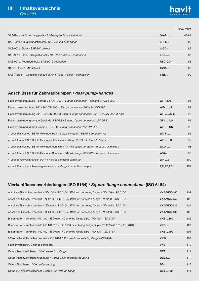
SAE-Reduzierflansch – gerade / SAE-adapter flange – straight G-AF-… 83/84
SAE-Tank-/Saugleitungsflansch / SAE-suction hose flange SHFL-… 85
SAE-90° L-Block / SAE-90° L-block L-GD-… 86
SAE-90° L-Block – Gegenflansch / SAE-90° L-block – companion L-BL-… 87
SAE-90° L-Reduzierblock / SAE-90° L-reduction RED-GD-… 88
SAE-T-Block / SAE-T-block T-GD-… 89
SAE-T-Block – Gegenflanschausführung / SAE-T-Block – companion T-BL-… 90
Anschlüsse für Zahnradpumpen / gear pump-flanges
Flanschverschraubung – gerade 24 °DIN 3901 / Flange connection – straight 24° DIN 3901 GF-…L/S 91
Flanschverschraubung 90° – 24° DIN 3901 / Flange connection 90° – 24° DIN 3901 WF-…L/S 92
Flanschverschraubung 90° – 24° DIN 3901 3-Loch / Flange connection 90° – 24° DIN 3901 3-hole WF-…L/S-3 93
Flanschverbindung gerade Gewinde UN-ORS / Straigth flange connection UN-ORS GF - … UN 94
Flanschverbindung 90° Gewinde UN/ORS / Flange connection 90° UN-ORS WF -… UN 95
3-Loch Flansch 90° BSPP-Gewinde Stahl / 3-hole flange 90° BSPP-threaded steel WDS-… 96
4-Loch Flansch 90° BSPP-Gewinde Stahl / 4-hole flange 90° BSPP-threaded steel WF -…. G 97
3-Loch Flansch 90° BSPP-Gewinde Aluminium / 3-hole flange 90° BSPP-threaded aluminium WDA-… 98
4-Loch Flansch 90° BSPP-Gewinde Aluminium / 4-hole flange 90° BSPP-threaded aluminium WVA-… 99
4-Loch Einschweißflansch 90° / 4-hole socket weld flange 90° WF-…E 100
4-Loch Flanschanschluss – gerade / 4-hole flange connection straight F,Fi,FE,FB-… 101
Vierkantflanschverbindungen (ISO 6164) / Square flange connections (ISO 6164)
Anschweißflansch – zentriert – ND 160 – ISO 6164 / Weld-on centering flange – ND 160 – ISO 6164 VKA/VKK-160 102
Anschweißflansch – zentriert – ND 250 – ISO 6164 / Weld-on centering flange – ND 250 – ISO 6164 VKA/VKK-250 103
Anschweißflansch – zentriert – ND 315 – ISO 6164 / Weld-on centering flange – ND 315 – ISO 6164 VKA/VKK-315 104
Anschweißflansch – zentriert – ND 400 – ISO 6164 / Weld-on centering flange – ND 400 – ISO 6164 VKA/VKK-400 105
Blindstopfen – zentriert – ND 160 – ISO 6164 / Centering flange plug – ND 160 – ISO 6164 VKB-...160 106
Blindstopfen – zentriert – ND 250 ND 315 – ISO 6164 / Centering flange plug – ND 250 ND 315 – ISO 6164 VKB-... 107
Blindstopfen – zentriert – ND 400 – ISO 6164 / Centering flange plug – ND 400 – ISO 6164 VKB-...400 108
90°-Anschweißflansch – zentriert – ISO 6164 / 90°-Weld-on centering flange – ISO 6164 VKW 109
Flanschverbinder / T-flange connector VKV 110
Cetop-Anschweißflansch / Cetop-weld-on flange CET 111
Cetop-Anschweißflanschkupplung / Cetop-weld-on flange-coupling DCET… 112
Cetop-Blindflansch / Cetop-flange plug BS- 113
Cetop 90° Anschweißflansch / Cetop 90° weld-on flange CET-…/90 114
IV | Technische Informationen Technical information
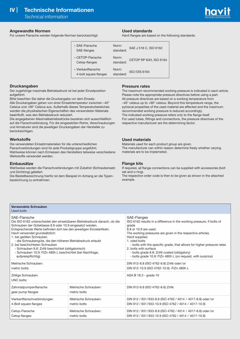
Angewandte NormenFür unsere Flansche werden folgende Normen berücksichtigt:
DruckangabenDer zugehörige maximale Betriebsdruck ist bei jeder Einzelposition aufgeführt.Bitte beachten Sie daher die Druckangabe vor dem Einsatz.Alle Druckangaben gehen von einer Einsatztemperatur zwischen –40° Celsius und +90° Celsius aus. Außerhalb dieses Temperaturbereiches werden die physikalischen Eigenschaften des verwendeten Materials beeinflußt, was den Betriebsdruck reduziert.Die angegebenen Maximalbetriebsdrücke beziehen sich ausschließlich auf die Flanschverbindung. Für die eingesetzten Rohre, Verschraubungen und Armaturen sind die jeweiligen Druckangaben der Hersteller zu berücksichtigen.
WerkstoffeDie verwendeten Einsatzmaterialien für die unterschiedlichen Flanschverbindungen sind für jede Produktgruppe angeführt.Wahlweise können nach Ermessen des Herstellers teilweise verschiedene Werkstoffe verwendet werden.
EinbausätzeWahlweise werden die Flanschverbindungen mit Zubehör (Schraubensatz und Dichtring) geliefert.Die Bestellbezeichnung hierfür ist dem Beispiel im Anhang an die Typen-bezeichnung zu entnehmen.
– SAE-Flansche Norm: SAE J 518 C, ISO 6162
SAE-flanges standard:
– CETOP-Flansche Norm: CETOP RP 63H, ISO 6164
Cetop-flanges standard:
– Vierkantflansche Norm: ISO/DIS 6164
4-bolt square flanges standard:
Used standardsHavit flanges are based on the following standards:
Pressure ratesThe maximum recommended working pressure is indicated in each article.Please note the appropriate pressure directives before using a part.All pressure directives are based on a working temperature from –40° celsius up to +90° celsius. Beyond this temperature range, the pyhsical properties of the used material are effected and the maximum recommended working pressure is reduced accordingly.The indicated working pressure refers only to the flange itself.For used tubes, fittings and connections, the pressure directives of the respective manufacturer are the determining factor.
Used materialsMaterials used for each product group are given.The manufacturer can within reason determine freely whether varyingmaterials are to be implemeted.
Flange kitsIf required, all flange connections can be supplied with accessories (bolt set and o-ring).The respective order code is then to be given as shown in the attached example.
Verwendete SchraubenUsed bolts
SAE-FlanscheDie ISO 6162 unterscheidet den einsetzbaren Betriebsdruck danach, ob die Schrauben der Güteklasse 8.8 oder 10.9 eingesetzt werden.Entsprechende Werte befinden sich bei den jeweiligen Einzelartikeln.Havit verwendet grundsätzlich:1. bei geölten Schrauben - die Schraubengüte, die den höheren Betriebsdruck erlaubt2. bei beschichteten Schrauben - Schrauben 8.8: ZnNi beschichtet (obligatorisch) - Schrauben 10.9: FlZn 480h L beschichtet (bei Nachfrage, aufpreispflichtig)
SAE-FlangesISO 6162 results in a difference in the working pressure, if bolts of grade8.8 or 10.9 are used.The working pressures are given in the respective articles.Havit supplies:1. oiled bolts - bolts with the specific grade, that allows for higher pressure rates2. bolts with surface - bolts grade 8.8: ZnNi coated (obligatory) - bolts grade 10.9: FlZn 480h L (on request, with surprice)
Metrische Schrauben:
metric bolts:
DIN 912-8.8 (ISO 4762-8.8) ZnNi oder/or
DIN 912-10.9 (ISO 4762-10.9) -FlZn 480h L
Zöllige Schrauben:
UNC bolts:
ASA B 18.3 - grade 10
Zahnradpumpenflansche
gear pump flanges
Metrische Schrauben:
metric bolts
DIN 912-8.8 (ISO 4762-8.8) ZnNi
Vierkantflanschverbindungen
4-Bolt square flanges
Metrische Schrauben:
metric bolts
DIN 912 / 931/933-8.8 (ISO 4762 / 4014 / 4017-8.8) oder/or
DIN 912 / 931/933-10.9 (ISO 4762 / 4014 / 4017-10.9)
Cetop-Flansche
Cetop flanges
Metrische Schrauben:
metric bolts
DIN 912 / 931/933-8.8 (ISO 4762 / 4014 / 4017-8.8) oder/or
DIN 912 / 931/933-10.9 (ISO 4762 / 4014 / 4017-10.9)

V | Technische Informationen Technical information
OberflächenschutzSoweit bei den einzelnen Artikelgruppen keine Angaben gemacht sind, werden die Flanschverbindungen als Blankstahl – mit Korrosionsschutz versehen – geliefert.
Verrohrung von FlanschverbindungenWir empfehlen für die Verrohrung unserer Flansche die Verwendung der folgenden Rohre:
– Präzisionsrohre nach DIN EN 10305-1, Güteklasse C normalisierend blankgeglüht (NBK) und nahtlos blankgezogen Material: ST 37-4 oder ST 52-4
– nahtlose Siederohre nach DIN EN 10220, Reihe 1 und 2 aus St 37-4 und ST 52-4
– Rohre nach ASME B36.10M
Für die einzelnen Flanschgrößen und Druckstufen empfehlen wir folgende Rohrabmessungen:
Surface protectionAs far as no special directives exist on a product range, all flanges aredelivered in blank steel and coated to protect against corrosion.
Flange tube connectionsFor tube connections with our flanges we recommend tubes which meet with the following standards:
– seamless precision steel pipes to DIN EN 10305-1, grade C materials ST 37-4 or ST 52-4– seamless boiling tubes to DIN EN 10220, group 1 and 2 from materials
ST 37-4 and ST 52-4– tubes according to ASME B36.10M
For the flange sizes and pressure rates we recommend the following tube dimensions:
DichtungenAlle Flanschverbindungen dieses Kataloges dichten mit einer Rundring-dichtung. Unsere Dichtungen sind lieferbar in folgenden Materialien:
– Perbunan Härte 90 Shore (Standard)– Viton Härte 85–90 Shore (auf Wunsch)
Bei SAE Flanschen und CETOP Flanschen werden grundsätzlich die O-Ring abmessungen gemäß nachstehender Tabelle berücksichtigt.Sind andere als diese standardisierten O-Ringe vorgesehen so sind diese bei den Einzelartikeln angeführt.
SealsAll flange connections shown in this catalogue are sealed using o-rings. The o-rings supplied by Havit are made from the following materials:
– buna 90 shore (standard) – viton 85–90 shore (option)
For all SAE flanges and Cetop flanges, the o-ring dimensions are to be read as according to the following table.O-rings differing from these dimensions are listed in the respective articleshowing their exact dimensions accordingly.
Größesize
A B
³⁄₈" 17,12 2,62
¹ ⁄₂" 18,66 3,53
³⁄₄" 25,00 3,53
1" 32,92 3,53
1¹⁄₄" 37,70 3,53
1¹ ⁄₂" 47,22 3,53
2" 56,75 3,53
2¹ ⁄₂" 69,45 3,53
3" 85,32 3,53
3¹ ⁄₂" 98,02 3,53
4" 110,72 3,53
5" 136,12 3,53
Flanschgrößeflange size
Rohre nach DIN EN 10305-1tubes to DIN EN 10305-1
Rohre nach DIN EN 10220tubes to DIN EN 10220
Rohre nach ASME B36.10Mtubes to ASME B36.10M
inch
Reihe /series Reihe /series Reihe /series
100 bar 160 bar 250 bar 315 bar 400 bar 250 bar 400 bar schedule 250 bar schedule 400 bar
¹ ⁄₂"15 x 1
18 x 1,516 x 2 16 x 2,5 16 x 3
21,3 x 2,6 21,3 x 3,2 40 21,3 x 2,8 80 21,3 x 3,718 x 1 20 x 2,5 20 x 3 20 x 3,5
³⁄₄" – – 25 x 3 25 x 3,5 25 x 4 26,9 x 2,6 26,9 x 4 40 26,7 x 2,9 80 26,7 x 3,9
1" 28 x 2 –28 x 3
30 x 5 30 x 6 33,7 x 4 33,7 x 6,3 40 33,7 x 4,8 160 33,7 x 6,430 x 4
1¹⁄₄" 35 x 2 –35 x 4
38 x 6 38 x 7 42,4 x 5 42,4 x 6,3 80 42,4 x 4,8 160 42,4 x 6,438 x 5
1¹⁄₂" 42 x 3 –42 x 5
50 x 8 50 x 9 48,3 x 5 48,3 x 8 80 48,3 x 5,1 160 48,3 x 7,150 x 6
2" – – – 65 x 8 65 x 10 60,3 x 6,3 60,3 x 10 160 60,3 x 8,7 200 60,3 x 11,1
2¹⁄₂" – – – 80 x 10 80 x 12 76,1 x 8 76,1 x 12,5 160 73 x 9,5 200 73 x 14
3" – – – – – 88,9 x 10 88,9 x 16 160 88,9 x 11,1 200 88,9 x 15,2
3¹⁄₂" – – – – – 101,6 x 10 101,6 x 16 – – – –
4" – – – – – 114,3 x 12,5 114,3 x 20 160 114,3 x 13,5 200 114,3 x 17,1

VI | Technische Informationen Technical information
Verwendete Schrauben: Schraubenanzugsmomente und Drücke für FlanschverbindungenUsed Bolts: Screw torques and pressures of flanged port assemblies
Schrauben 8.8Bolts 8.8
Schrauben 10.9 Bolts 10.9
Nenngrößenorminal size
Durchmesserdiameter
Anzugsmomentetightening torques
maximaler Betriebsdruckmaximum recommended
working pressure
Nenngrößenorminal size
Durchmesserdiameter
Anzugsmomentetightening torques
maximaler Betriebsdruckmaximum recommended
working pressure
ISO[DN]
SAE[inch]
+10% [NM] 0 [bar] ISO
[DN]SAE[inch]
+10% [NM] 0 [bar]
Standarddruckreihe (nach ISO 6162-1) 3.000 PSIStandard pressure series (according to ISO 6162-1) 3.000 PSI
Standarddruckreihe (nach ISO 6162-1) 3.000 PSIStandard pressure series (according to ISO 6162-1) 3.000 PSI
13 ¹ ⁄₂" M 8 24 350 13 ¹ ⁄₂" M8 32 350
19 ³⁄₄" M 10 50 350 19 ³⁄₄" M 10 70 350
25 1" M 10 50 250 25 1" M 10 70 320
32 1¹⁄₄" M 10 50 200 32 1¹⁄₄" M 10 70 280
38 1¹ ⁄₂" M 12 92 200 38 1¹ ⁄₂" M 12 130 210
51 2" M 12 92 160 51 2" M 12 130 210
64 2¹ ⁄₂" M 12 92 100 64 2¹ ⁄₂" M 12 130 175
76 3" M 16 210 100 76 3" M 16 295 160
89 3¹ ⁄₂" M 16 210 35 89 3¹ ⁄₂" M 16 295 35
102 4" M 16 210 35 102 4" M 16 295 35
127 5" M 16 210 35 127 5" M 16 295 35
Hochdruckreihe (nach ISO 6162-2) 6.000 PSIHigh pressure series (according to ISO 6162-2) 6.000 PSI
Hochdruckreihe (nach ISO 6162-2) 6.000 PSIHigh pressure series (according to ISO 6162-2) 6.000 PSI
13 ¹ ⁄₂" M 8 24 350 13 ¹ ⁄₂" M8 32 420
19 ³⁄₄" M 10 50 350 19 ³⁄₄" M 10 70 420
25 1" M 12 92 350 25 1" M 12 130 420
32 1¹⁄₄" M 12 92 350 32 1¹⁄₄" M 12 130 420
32 1¹⁄₄" M 14 *1 130 350 32 1¹⁄₄" M 14 *1 180 420
38 1¹ ⁄₂" M 16 210 350 38 1¹ ⁄₂" M 16 295 420
51 2" M 20 400 350 51 2" M 20 550 420
Schrauben UNC Grade 8Bolts UNC grade 8
Nenngrößenorminal size
Durchmesserdiameter
Anzugsmomentetightening torques
maximaler Betriebsdruckmaximum recommended
working pressure
ISO[DN]
SAE[inch]
+10% [NM] 0 [bar]
Standarddruckreihe (nach ISO 6162-1) 3.000 PSIStandard pressure series (according to ISO 6162-1) 3.000 PSI
13 ¹ ⁄₂" ⁵⁄₁₆-18 32 350
19 ³⁄₄" ³⁄₈-16 60 350
25 1" ³⁄₈-16 60 315
32 1¹⁄₄" ⁷⁄₁₆-14 92 250
38 1¹ ⁄₂" ¹ ⁄₂-13 150 200
51 2" ¹ ⁄₂-13 150 200
64 2¹ ⁄₂" ¹ ⁄₂-13 150 160
76 3" ⁵⁄₈-11 295 160
89 3¹ ⁄₂" ⁵⁄₈-11 295 35
102 4" ⁵⁄₈-11 295 35
127 5" ⁵⁄₈-11 295 35
Hochdruckreihe (nach ISO 6162-2) 6.000 PSIHigh pressure series (according to ISO 6162-2) 6.000 PSI
13 ¹ ⁄₂" ⁵⁄₁₆-18 32 400
19 ³⁄₄" ³⁄₈-16 60 400
25 1" ⁷⁄₁₆-14 92 400
32 1¹⁄₄" ¹ ⁄₂-13 150 400
38 1¹ ⁄₂" ⁵⁄₈-11 295 400
51 2" ³⁄₄-10 450 400
Hinweise/Notes
*1 Nicht für Neukonstruktionen zu verwenden.Not to be used for new constructions.
*2 Die angegebenen Anzugsmomente für UNC-Schrauben sind der Norm ISO 6162-1/2 entnommen und beziehen sich auf die Festig-keitsklasse "Grade 8". Verfügbar sind jedoch nur Schrauben der höheren Festigkeitsklasse "Grade 10".The tightening torques for UNC bolts as stated on the left apply to "grade 8" UNC bolts according to ISO 6162-1/2. Please note that we only have UNC bolts of the higher "grade 10" available.
Achtung: Alle Schrauben sind leicht anzuziehen, bevor das erforderliche Anzugsdrehmoment aufgebracht wird. Andernfalls kann es zum Bruch des Flansches kommen. Attention: All bolts have to be pre-tightened before applying the full tightening torque to the bolts. Otherwise, the flange may break.
Die angegebenen Drehmomente sind Empfehlungswerte. Sie beziehen sich auf geölte Schrauben, berechnet mit einem Reibbeiwert von 0,17 und der Materialpaarung Stahl/Stahl. Der zugelassene Wert hängt von vielen Faktoren (insbesondere Werkstoffe, Oberfläche, Beschichtung und Schmierung der zu verschraubenden Teile) ab und ist vom Anwen-der zu ermitteln.Please note that the tightening torques as stated above are only recommendations. These values correspond to oiled bolts with a friction coefficient of 0,17 and the material combination steel/steel. The exact tightening torques depend on factors like material, finishing, coating and lubrication of the components used, and have to be determined by the user himself.

VII |
Montageanleitung - FlanscheMounting instructions - flange
Schrauben 8.8Bolts 8.8
Schrauben 10.9 Bolts 10.9
Schrauben UNC Grade 8 *2
Bolts UNC grade 8 *2
Nenngrößenorminal size
Durchmesserdiameter
Anzugsmomentetightening torques
maximaler Betriebsdruckmax. recomm.
working pressure
Durchmesserdiameter
Anzugsmomentetightening torques
maximaler Betriebsdruckmax. recomm.
working pressure
Durchmesserdiameter
Anzugsmomentetightening torques
maximaler Betriebsdruckmax. recomm.
working pressure
ISO[DN]
SAE[inch]
+10% [NM] 0 [bar]
+10% [NM] 0 [bar]
+10% [NM] 0 [bar]
Standarddruckreihe (nach ISO 6162-1) 3.000 PSIStandard pressure series (according to ISO 6162-1) 3.000 PSI
13 ¹ ⁄₂" M 8 24 350 M 8 32 350 ⁵⁄₁₆-18 32 350
19 ³⁄₄" M 10 50 350 M 10 70 350 ³⁄₈-16 60 350
25 1" M 10 50 250 M 10 70 320 ³⁄₈-16 60 320
32 1¹⁄₄" M 10 50 200 M 10 70 280 ⁷⁄₁₆-14 92 280
38 1¹ ⁄₂" M 12 92 200 M 12 130 210 ¹ ⁄₂-13 150 210
51 2" M 12 92 160 M 12 130 210 ¹ ⁄₂-13 150 210
64 2¹ ⁄₂" M 12 92 100 M 12 130 175 ¹ ⁄₂-13 150 175
76 3" M 16 210 100 M 16 295 160 ⁵⁄₈-11 295 160
89 3¹ ⁄₂" M 16 210 35 M 16 295 35 ⁵⁄₈-11 295 35
102 4" M 16 210 35 M 16 295 35 ⁵⁄₈-11 295 35
127 5" M 16 210 35 M 16 295 35 ⁵⁄₈-11 295 35
Hochdruckreihe (nach ISO 6162-2) 6.000 PSIHigh pressure series (according to ISO 6162-2) 6.000 PSI
13 ¹ ⁄₂" M 8 24 350 M 8 32 420 ⁵⁄₁₆-18 32 420
19 ³⁄₄" M 10 50 350 M 10 70 420 ³⁄₈-16 60 420
25 1" M 12 92 350 M 12 130 420 ⁷⁄₁₆-14 92 420
32 1¹⁄₄" M 12 92 350 M 12 130 420 ¹ ⁄₂-13 150 420
32 1¹⁄₄" M 14 *1 130 350 M 14 *1 180 420 - - -
38 1¹ ⁄₂" M 16 210 350 M 16 295 420 ⁵⁄₈-11 295 420
51 2" M 20 400 350 M 20 550 420 ³⁄₄-10 450 420
*1 Nicht für Neukonstruktionen zu verwenden.Not to be used for new constructions.
*2 Die angegebenen Anzugsmomente für UNC-Schrauben sind der Norm ISO 6162-1/2 entnommen und beziehen sich auf die Festigkeitsklasse "Grade 8". Verfügbar sind jedoch nur Schrauben der höheren Festigkeitsklasse "Grade 10".The tightening torques for UNC bolts as stated on the left apply to "grade 8" UNC bolts according to ISO 6162-1/2. Please note that we only have UNC bolts of the higher "grade 10" available.
Schritt 1• Prüfen Sie die Dichtfläche und O-Ringnut. Diese müssen von
Graden, fremden Partikeln und sonstigen Beschädigungen frei sein
• O-Ring mit Systemflüssigkeit schmieren und in die O-Ringnut einlegen
Step 1• Check the connecting surface and the O-ring groove. Both
must be free of all scratches, particles and any damage• Smear the O-ring with system fluid and place it in the O-ring
groove
Schritt 2• Positionierung des Flansches zum Gegenstück• Handfeste Vormontage der Schrauben (mit Federring optional)
Step 2• Position the flange against the matching component• Mount the bolts and initially tighten per hand (spring washer
is optional)
Schritt 3• Festdrehen der Schrauben, in der Reihenfolge 1-4, auf das
empfohlene Anzugsmoment• WICHTIG: Alle Schrauben müssen vor dem Aufbringen des
empfohlenen Anzugmomentes leicht angezogen werden, damit ein Bruch vermieden wird
Step 3• Tighten the bolts in the displayed sequence according to the
recommended torque• IMPORTANT: To avoid damage, tighten each bolt lightly in
sequence before administrating the recommended torque
VII | Technische Informationen Technical information

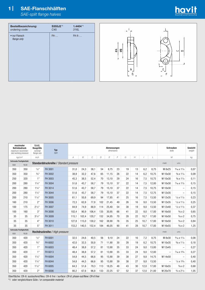
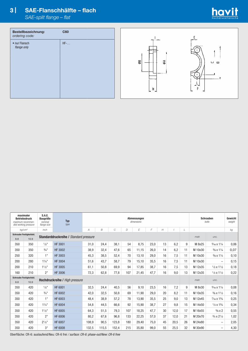
1 |
Oberfläche: CR-6: auslaufend/Neu: CR-6 frei / surface: CR-6: phase-out/New: CR-6 free*1 oder vergleichbare Güte / or comparable material
Bestellbezeichnung:ordering code:
S355J2 *1
C451.4404 *1
316L
• nur Flansch flange only
FH-… FH-X-…
1 | SAE-Flanschhälften SAE-split flange halves
maximaler Betriebsdruck
maximum recommen-ded working pressure
S.A.E. Baugröße
nominal flange size
Typtype
Abmessungendimensions
Schraubenbolts
Gewichtweight
kg/cm² inch A B C D E F G H I L M kg
Schraube Festigkeitskl.Standarddruckreihe / Standard pressure metr. unc.
8.8 10.9
350 350 ¹ ⁄₂" FH 3001 31,0 24,3 38,1 54 8,75 23 19 13 6,2 8,75 M 8x25 ⁵⁄₁₆ x 1¹⁄₄ 0,07
350 350 ³⁄₄" FH 3002 38,9 32,2 47,6 65 11,15 26 22 14 6,2 10,75 M 10x30 ³⁄₈ x 1¹⁄₄ 0,09
250 320 1" FH 3003 45,3 38,5 52,4 70 13,10 29 24 16 7,5 10,75 M 10x30 ³⁄₈ x 1¹⁄₄ 0,11
200 280 1¹⁄₄" FH 3004 51,6 43,7 58,7 79 15,10 37 22 14 7,5 12,00 M 10x30 ⁷⁄₁₆ x 1¹⁄₂ 0,15
200 280 1¹⁄₄" FH 3014 51,6 43,7 58,7 79 15,10 37 22 14 7,5 10,75 M 10x30 – 0,15
200 280 1¹⁄₄" FH 3044 51,6 43,7 58,7 79 15,10 37 22 14 7,5 12,75 M 12x35 – 0,15
200 210 1¹ ⁄₂" FH 3005 61,1 50,8 69,9 94 17,85 41 25 16 7,5 13,50 M 12x35 ¹ ⁄₂ x 1¹ ⁄₂ 0,23
160 210 2" FH 3006 72,3 62,8 77,8 102 21,45 49 26 16 9,0 13,50 M 12x35 ¹ ⁄₂ x 1¹ ⁄₂ 0,25
100 175 2¹ ⁄₂" FH 3007 84,9 74,9 88,9 114 25,40 54 38 19 9,0 13,50 M 12x40 ¹ ⁄₂ x 1¹ ⁄₂ 0,37
100 160 3" FH 3008 102,4 90,9 106,4 135 30,95 66 41 22 9,0 17,00 M 16x50 ⁵⁄₈ x 2 0,65
35 35 3¹ ⁄₂" FH 3009 115,1 102,4 120,7 152 34,95 70 28 22 10,7 17,00 M 16x50 ⁵⁄₈ x 2 0,75
35 35 4" FH 3010 127,8 115,0 130,2 162 38,90 76 35 25 10,7 17,00 M 16x50 ⁵⁄₈ x 2 0,84
35 35 5" FH 3011 153,2 140,5 152,4 184 46,05 90 41 28 10,7 17,00 M 16x55 ⁵⁄₈ x 2 1,25Schraube Festigkeitskl.
Hochdruckreihe / High pressure metr. unc.8.8 10.9
350 420 ¹ ⁄₂" FH 6001 32,5 24,6 40,5 56 9,10 24 22 16 7,2 8,75 M 8x30 ⁵⁄₁₆ x 1¹⁄₄ 0,08
350 420 ³⁄₄" FH 6002 42,0 32,5 50,8 71 11,90 30 28 19 8,2 10,75 M 10x35 ³⁄₈ x 1¹ ⁄₂ 0,18
350 420 1" FH 6003 48,4 38,8 57,2 81 13,90 35 33 24 9,0 13,00 M 12x45 – 0,27
350 420 1" FH 6013 48,4 38,8 57,2 81 13,90 35 33 24 9,0 12,00 – ⁷⁄₁₆ x 1³⁄₄ 0,27
350 420 1¹⁄₄" FH 6004 54,8 44,5 66,6 95 15,90 39 38 27 9,8 14,75 M 14x50 – 0,40
350 420 1¹⁄₄" FH 6044 54,8 44,5 66,6 95 15,90 39 38 27 9,8 13,50 – ¹ ⁄₂ x 1³⁄₄ 0,40
350 420 1¹ ⁄₂" FH 6005 64,3 51,6 79,3 113 18,25 48 43 30 12,0 17,00 M 16x55 ⁵⁄₈ x 2 0,68
350 420 2" FH 6006 80,2 67,6 96,8 133 22,25 57 52 37 12,0 21,00 M 20x70 ³⁄₄ x 2¹ ⁄₂ 1,05

2 |
Oberfläche: CR-6: auslaufend/Neu: CR-6 frei / surface: CR-6: phase-out/New: CR-6 free*1 oder vergleichbare Güte / or comparable material
Bestellbezeichnung:ordering code:
S355J2 *1
C451.4404 *1
316L
• nur Flansch flange only
VF-… VF-X-…
2 | SAE-Vollflansche SAE-flange clamp
maximaler Betriebsdruck
maximum recommen-ded working pressure
S.A.E. Baugröße
nominal flange size
Typtype
Abmessungendimensions
Schraubenbolts
Gewichtweight
kg/cm² inch A B C D E F G H I L kg
Schraube Festigkeitskl.Standarddruckreihe / Standard pressure metr. unc.
8.8 10.9
350 350 ¹ ⁄₂" VF 3001 31,0 24,3 38,1 54 17,5 46 19 13 6,2 8,75 M 8x25 ⁵⁄₁₆ x 1¹⁄₄ 0,14
350 350 ³⁄₄" VF 3002 38,9 32,2 47,6 65 22,3 52 22 14 6,2 10,75 M 10x30 ³⁄₈ x 1¹⁄₄ 0,17
250 320 1" VF 3003 45,3 38,5 52,4 70 26,2 59 24 16 7,5 10,75 M 10x30 ³⁄₈ x 1¹⁄₄ 0,22
200 280 1¹⁄₄" VF 3004 51,6 43,7 58,7 79 30,2 73 22 14 7,5 12,00 M 10x30 ⁷⁄₁₆ x 1¹ ⁄₂ 0,30
350 400 1¹⁄₄" VF 3004-6000 psi 51,6 43,7 58,7 79 30,2 73 33 24 7,5 12,50 M 12x45 – 0,50
200 210 1¹ ⁄₂" VF 3005 61,1 50,8 69,9 94 35,7 83 25 16 7,5 13,50 M 12x35 ¹ ⁄₂ x 1¹ ⁄₂ 0,45
160 210 2" VF 3006 72,3 62,8 77,8 102 42,9 97 26 16 9,0 13,50 M 12x35 ¹ ⁄₂ x 1¹ ⁄₂ 0,50
350 400 2" VF 3006-6000 psi 72,3 62,8 77,8 102 42,9 97 43 30 9,0 13,50 M 12x50 – 1,38
100 175 2¹ ⁄₂" VF 3007 84,9 74,9 88,9 114 50,8 109 38 19 9,0 13,50 M 12x40 ¹ ⁄₂ x 1¹ ⁄₂ 0,74
100 160 3" VF 3008 102,4 90,9 106,4 135 61,9 131 41 22 9,0 17,00 M 16x50 ⁵⁄₈ x 2 1,30
35 35 3¹ ⁄₂" VF 3009 115,1 102,4 120,7 152 69,9 140 28 22 10,7 17,00 M 16x50 ⁵⁄₈ x 2 1,50
35 35 4" VF 3010 127,8 115,0 130,2 162 77,8 152 35 25 10,7 17,00 M 16x50 ⁵⁄₈ x 2 1,65
35 35 5" VF 3011 153,2 140,5 152,4 184 92,1 181 41 28 10,7 17,00 M 16x55 ⁵⁄₈ x 2 2,50Schraube Festigkeitskl.
Hochdruckreihe / High pressure metr. unc.8.8 10.9
350 420 ¹ ⁄₂" VF 6001 32,5 24,6 40,5 56 18,2 48 22 16 7,2 8,75 M 8x30 ⁵⁄₁₆ x 1¹⁄₄ 0,16
350 420 ³⁄₄" VF 6002 42,0 32,5 50,8 71 23,8 60 28 19 8,2 10,75 M 10x35 ³⁄₈ x 1¹ ⁄₂ 0,35
350 420 1" VF 6003 48,4 38,8 57,2 81 27,8 70 33 24 9,0 13,00 M 12x45 – 0,53
350 420 1" VF 6003-12 48,4 38,8 57,2 81 27,8 70 33 24 9,0 12,00 – ⁷⁄₁₆ x 1³⁄₄ 0,53
350 420 1¹⁄₄" VF 6004 54,8 44,5 66,6 95 31,8 78 38 27 9,8 14,75 M 14x50 ¹ ⁄₂ x 1³⁄₄ 0,80
350 420 1¹ ⁄₂" VF 6005 64,3 51,6 79,3 113 36,5 95 43 30 12,0 17,00 M 16x55 ⁵⁄₈ x 2 1,35
350 420 2" VF 6006 80,2 67,6 96,8 133 44,5 114 52 37 12,0 21,00 M 20x70 ³⁄₄ x 2¹ ⁄₂ 2,10
350 420 2¹ ⁄₂" VF 6007 108,9 90,5 123,8 180 58,8 152 45 45 20,5 26,00 M 24x80 – 4,10
350 420 3" VF 6008 132,5 115,5 152,4 215 71,6 198 55 55 25,5 32,00 M 30x90 – 8,60
3 |
Oberfläche: CR-6: auslaufend/Neu: CR-6 frei / surface: CR-6: phase-out/New: CR-6 free
Bestellbezeichnung:ordering code:
C60
• nur Flansch flange only
HF-…
3 | SAE-Flanschhälfte – flach SAE-split flange – flat
maximaler Betriebsdruck
maximum recommen-ded working pressure
S.A.E. Baugröße
nominal flange size
Typtype
Abmessungendimensions
Schraubenbolts
Gewichtweight
kg/cm² inch A B C D E F H I L kg
Schraube Festigkeitskl.Standarddruckreihe / Standard pressure metr. unc.
8.8 10.9
350 350 ¹ ⁄₂" HF 3001 31,0 24,4 38,1 54 8,75 23,0 13 6,2 9 M 8x25 ⁵⁄₁₆ x 1¹⁄₄ 0,06
350 350 ³⁄₄" HF 3002 38,9 32,4 47,6 65 11,15 26,0 14 6,2 11 M 10x30 ³⁄₈ x 1¹⁄₄ 0,07
250 320 1" HF 3003 45,3 38,5 52,4 70 13,10 29,0 16 7,5 11 M 10x30 ³⁄₈ x 1¹⁄₄ 0,10
200 280 1¹⁄₄" HF 3004 51,6 43,7 58,7 79 15,10 35,5 16 7,5 11 M 10x30 – 0,15
200 210 1¹ ⁄₂" HF 3005 61,1 50,8 69,9 94 17,85 38,7 16 7,5 13 M 12x35 ¹ ⁄₂ x 1¹ ⁄₂ 0,18
160 210 2" HF 3006 72,3 62,8 77,8 107 21,45 47,7 16 9,0 13 M 12x35 ¹ ⁄₂ x 1¹ ⁄₂ 0,22Schraube Festigkeitskl.
Hochdruckreihe / High pressure metr. unc.8.8 10.9
350 420 ¹ ⁄₂" HF 6001 32,5 24,4 40,5 56 9,10 23,5 16 7,2 9 M 8x30 ⁵⁄₁₆ x 1¹⁄₄ 0,08
350 420 ³⁄₄" HF 6002 42,0 32,5 50,8 69 11,90 29,0 20 8,2 11 M 10x35 ³⁄₈ x 1¹ ⁄₂ 0,16
350 420 1" HF 6003 48,4 38,9 57,2 78 13,90 35,5 25 9,0 13 M 12x45 ⁷⁄₁₆ x 1³⁄₄ 0,25
350 420 1¹⁄₄" HF 6004 54,8 44,5 66,6 92 15,90 38,7 27 9,8 15 M 14x50 ¹ ⁄₂ x 1³⁄₄ 0,34
350 420 1¹ ⁄₂" HF 6005 64,3 51,5 79,3 107 18,25 47,7 30 12,0 17 M 16x55 ⁵⁄₈ x 2 0,55
350 420 2" HF 6006 80,2 67,6 96,8 133 22,25 57,0 37 12,0 21 M 20x70 ³⁄₄ x 2¹ ⁄₂ 1,02
350 420 2¹ ⁄₂" HF 6007 108,9 90,5 123,8 180 29,40 75,0 45 20,5 26 M 24x80 – 2,05
350 420 3" HF 6008 132,5 115,5 152,4 215 35,80 99,0 55 25,5 32 M 30x90 – 4,30

Oberfläche: CR-6: auslaufend/Neu: CR-6 frei / surface: CR-6: phase-out/New: CR-6 free
Bestellbezeichnung:ordering code:
C60
• nur Flansch flange only
VFH-…
4 | SAE-Vollflansch – flach SAE-flange clamp – flat
maximaler Betriebsdruck
maximum recommen-ded working pressure
S.A.E. Baugröße
nominal flange size
Typtype
Abmessungendimensions
Schraubenbolts
Gewichtweight
kg/cm² inch A B C D E F H I L M kg
Schraube Festigkeitskl.Standarddruckreihe / Standard pressure metr. unc.
8.8 10.9
350 350 ¹ ⁄₂" VFH 3001 31,0 24,3 38,1 54 17,5 46 13 6,2 8,75 M 8x25 ⁵⁄₁₆ x 1¹⁄₄ 0,15
350 350 ³⁄₄" VFH 3002 38,9 32,2 47,6 65 22,3 52 14 6,2 10,75 M 10x30 ³⁄₈ x 1¹⁄₄ 0,17
250 320 1" VFH 3003 45,3 38,5 52,4 70 26,2 59 16 7,5 10,75 M 10x30 ³⁄₈ x 1¹⁄₄ 0,22
200 280 1¹⁄₄" VFH 3004 51,6 43,7 58,7 79 30,2 73 16 7,5 12,00 M 10x30 ⁷⁄₁₆ x 1¹ ⁄₂ 0,30
200 210 1¹ ⁄₂" VFH 3005 61,1 50,8 69,9 94 35,7 83 16 7,5 13,50 M 12x35 ¹ ⁄₂ x 1¹ ⁄₂ 0,45
160 210 2" VFH 3006 72,3 62,8 77,8 102 42,9 97 16 9,0 13,50 M 12x35 ¹ ⁄₂ x 1¹ ⁄₂ 0,50Schraube Festigkeitskl.
Hochdruckreihe / High pressure metr. unc.8.8 10.9
350 420 ¹ ⁄₂" VFH 6001 32,5 24,6 40,5 56 18,2 48 16 7,2 8,75 M 8x30 ⁵⁄₁₆ x 1¹⁄₄ 0,16
350 420 ³⁄₄" VFH 6002 42,0 32,5 50,8 71 23,8 60 20 8,2 10,75 M 10x35 ³⁄₈ x 1¹ ⁄₂ 0,35
350 420 1" VFH 6003 48,4 38,8 57,2 81 27,8 70 25 9,0 13,00 M 12x45 – 0,53
350 420 1¹⁄₄" VFH 6004 54,8 44,5 66,6 95 31,8 78 27 9,8 14,75 M 14x50 ¹ ⁄₂ x 1³⁄₄ 0,80
350 420 1¹ ⁄₂" VFH 6005 64,3 51,6 79,3 113 36,5 95 30 12,0 17,00 M 16x55 ⁵⁄₈ x 2 1,35
350 420 2" VFH 6006 80,2 67,6 96,8 133 44,5 114 37 12,0 21,00 M 20x70 ³⁄₄ x 2¹ ⁄₂ 2,10

5 | SAE-Vollflansch mit metrischen Gewinden SAE-flange clamp metric tapped
Oberfläche: CR-6: auslaufend/Neu: CR-6 frei / surface: CR-6: phase-out/New: CR-6 free*1 oder vergleichbare Güte / or comparable material
Bestellbezeichnung:ordering code:
S355J2*1
C451.4404*1
316L
• nur Flansch flange only
VFG-… VFG-X-…
maximaler Betriebsdruck
maximum recommen-ded working pressure
S.A.E. Baugröße
nominal flange size
Typtype
Abmessungendimensions
Gewichtweight
kg/cm² inch A B C D E F G H I M kg
Schraube Festigkeitskl.Standarddruckreihe / Standard pressure
8.8 10.9
350 350 ¹ ⁄₂" VFG 3001 31,0 24,3 38,1 54 17,5 46 19 13 6,2 M 8 0,15
350 350 ³⁄₄" VFG 3002 38,9 32,2 47,6 65 22,3 52 22 14 6,2 M 10 0,17
250 320 1" VFG 3003 45,3 38,5 52,4 70 26,2 59 24 16 7,5 M 10 0,22
200 280 1¹⁄₄" VFG 3004 51,6 43,7 58,7 79 30,2 73 22 14 7,5 M 10 0,30
200 210 1¹ ⁄₂" VFG 3005 61,1 50,8 69,9 94 35,7 83 25 16 7,5 M 12 0,45
160 210 2" VFG 3006 72,3 62,8 77,8 102 42,9 97 26 16 9,0 M 12 0,50
100 175 2¹ ⁄₂" VFG 3007 84,9 74,9 88,9 114 50,8 109 38 19 9,0 M 12 0,88
100 160 3" VFG 3008 102,4 90,9 106,4 135 61,9 131 41 22 9,0 M 16 1,30
35 35 3¹ ⁄₂" VFG 3009 115,1 102,4 120,7 152 69,9 140 28 22 10,7 M 16 1,29
35 35 4" VFG 3010 127,8 115,0 130,2 162 77,8 152 35 25 10,7 M 16 1,65
35 35 5" VFG 3011 153,2 140,5 152,4 184 92,1 181 41 28 10,7 M 16 2,50Schraube Festigkeitskl.
Hochdruckreihe / High pressure8.8 10.9
350 420 ¹ ⁄₂" VFG 6001 32,5 24,6 40,5 56 18,2 48 22 16 7,2 M 8 0,16
350 420 ³⁄₄" VFG 6002 42,0 32,5 50,8 71 23,8 60 28 19 8,2 M 10 0,35
350 420 1" VFG 6003 48,4 38,8 57,2 81 27,8 70 33 24 9,0 M 12 0,53
350 420 1¹⁄₄" VFG 6004 54,8 44,5 66,6 95 31,8 78 38 27 9,8 M 14 0,80
350 420 1¹ ⁄₂" VFG 6005 64,3 51,6 79,3 113 36,5 95 43 30 12,0 M 16 1,35
350 420 2" VFG 6006 80,2 67,6 96,8 133 44,5 114 52 37 12,0 M 20 2,10
350 420 2¹ ⁄₂" VFG 6007 108,9 90,5 123,8 180 58,8 152 45 45 20,5 M 24 4,10
350 420 3" VFG 6008 132,5 115,5 152,4 215 71,6 198 55 55 25,5 M 30 8,60
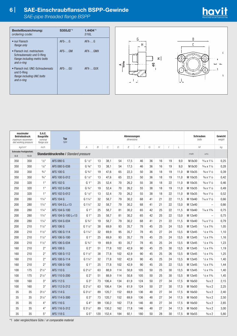
Bestellbezeichnung:ordering code:
S355J2 *1 1.4404 *1
316L
• nur Flansch flange only
AFS-…G AFX-…G
• Flansch incl. metrischem Schraubensatz und O-Ring flange including metric bolts and o-ring
AFS-…GM AFX-…GMX
• Flansch incl. UNC-Schraubensatz und O-Ring flange including UNC bolts and o-ring
AFS-…GU AFX-…GUX
6 | SAE-Einschraubflansch BSPP-Gewinde SAE-pipe threaded flange BSPP
*1 oder vergleichbare Güte / or comparable material
maximaler Betriebsdruck
maximum recommen-ded working pressure
S.A.E. Baugröße
nominal flange size
Typtype
Abmessungendimensions
Schraubenbolts
Gewichtweight
kg/cm² inch A B C D E F G H I L M kg
Schraube Festigkeitskl.Standarddruckreihe / Standard pressure metr. unc.
8.8 10.9
350 350 ¹ ⁄₂" AFS 080 G G ¹ ⁄₂" 13 38,1 54 17,5 46 36 16 19 9,0 M 8x30 ⁵⁄₁₆ x 1¹⁄₄ 0,25
350 350 ¹ ⁄₂" AFS 080 G-038 G ³⁄₈" 13 38,1 54 17,5 46 36 16 19 9,0 M 8x30 ⁵⁄₁₆ x 1¹⁄₄ 0,28
350 350 ³⁄₄" AFS 100 G G ³⁄₄" 19 47,6 65 22,3 50 36 18 19 11,0 M 10x35 ³⁄₈ x 1¹ ⁄₂ 0,39
350 350 ³⁄₄" AFS 100 G-012 G ¹ ⁄₂" 13 47,6 65 22,3 50 36 18 19 11,0 M 10x35 ³⁄₈ x 1¹ ⁄₂ 0,42
250 320 1" AFS 102 G G 1" 25 52,4 70 26,2 55 38 18 22 11,0 M 10x35 ³⁄₈ x 1¹ ⁄₂ 0,46
250 320 1" AFS 102 G-034 G ³⁄₄" 19 52,4 70 26,2 55 38 18 19 11,0 M 10x35 ³⁄₈ x 1¹ ⁄₂ 0,49
250 320 1" AFS 102 G-012 G ¹ ⁄₂" 13 52,4 70 26,2 55 38 18 22 11,0 M 10x35 ³⁄₈ x 1¹ ⁄₂ 0,52
200 280 1¹⁄₄" AFS 104 G G 1¹⁄₄" 32 58,7 79 30,2 68 41 21 22 11,5 M 10x40 ⁷⁄₁₆ x 1¹ ⁄₂ 0,66
200 280 1¹⁄₄" AFS 104 G L=13 G 1¹⁄₄" 32 58,7 79 30,2 68 41 21 22 13,0 M 12x40 – 0,66
200 280 1¹⁄₄" AFS 104 G-100 G 1" 25 58,7 81 30,2 65 42 25 22 11,5 M 10x40 ⁷⁄₁₆ x 1³⁄₄ 0,75
200 280 1¹⁄₄" AFS 104 G-100 L=13 G 1" 25 58,7 81 30,2 65 42 25 22 13,0 M 12x40 – 0,75
200 280 1¹⁄₄" AFS 104 G-034 G ³⁄₄" 19 58,7 79 30,2 68 41 21 22 11,5 M 10x40 ⁷⁄₁₆ x 1¹ ⁄₂ 0,79
200 210 1¹ ⁄₂" AFS 106 G G 1¹ ⁄₂" 38 69,9 93 35,7 78 45 25 24 13,5 M 12x45 ¹ ⁄₂ x 1³⁄₄ 1,05
200 210 1¹ ⁄₂" AFS 106 G-114 G 1¹⁄₄" 32 69,9 95 35,7 78 45 27 24 13,5 M 12x45 ¹ ⁄₂ x 1³⁄₄ 1,10
200 210 1¹ ⁄₂" AFS 106 G-100 G 1" 25 69,9 93 35,7 78 45 25 24 13,5 M 12x45 ¹ ⁄₂ x 1³⁄₄ 1,16
200 210 1¹ ⁄₂" AFS 106 G-034 G ³⁄₄" 19 69,9 93 35,7 78 45 25 24 13,5 M 12x45 ¹ ⁄₂ x 1³⁄₄ 1,23
160 210 2" AFS 108 G G 2" 51 77,8 102 42,9 90 45 25 30 13,5 M 12x45 ¹ ⁄₂ x 1³⁄₄ 1,19
160 210 2" AFS 108 G-112 G 1¹ ⁄₂" 38 77,8 102 42,9 90 45 25 26 13,5 M 12x45 ¹ ⁄₂ x 1³⁄₄ 1,25
160 210 2" AFS 108 G-114 G 1¹⁄₄" 32 77,8 102 42,9 90 45 25 24 13,5 M 12x45 ¹ ⁄₂ x 1³⁄₄ 1,40
160 210 2" AFS 108 G-100 G 1" 25 77,8 102 42,9 90 45 25 22 13,5 M 12x45 ¹ ⁄₂ x 1³⁄₄ 1,44
100 175 2¹ ⁄₂" AFS 110 G G 2¹ ⁄₂" 63 88,9 114 50,8 105 50 25 30 13,5 M 12x45 ¹ ⁄₂ x 1³⁄₄ 1,40
100 175 2¹ ⁄₂" AFS 110 G-200 G 2" 51 88,9 114 50,8 105 50 25 30 13,5 M 12x45 ¹ ⁄₂ x 1³⁄₄ 1,45
100 160 3" AFS 112 G G 3" 73 106,4 134 61,9 124 50 27 34 17,5 M 16x50 ⁵⁄₈ x 2 2,15
100 160 3" AFS 112 G-212 G 2¹ ⁄₂" 63 106,4 134 61,9 124 50 27 30 17,5 M 16x50 ⁵⁄₈ x 2 2,25
35 35 3¹ ⁄₂" AFS 114 G G 3¹ ⁄₂" 89 120,7 152 69,9 136 48 27 34 17,5 M 16x50 ⁵⁄₈ x 2 2,40
35 35 3¹ ⁄₂" AFS 114 G-300 G 3" 73 120,7 152 69,9 136 48 27 34 17,5 M 16x50 ⁵⁄₈ x 2 2,50
35 35 4" AFS 116 G G 4" 99 130,2 162 77,8 146 48 27 34 17,5 M 16x50 ⁵⁄₈ x 2 2,85
35 35 4" AFS 116 G-312 G 3¹ ⁄₂" 89 130,2 162 77,8 146 48 27 34 17,5 M 16x50 ⁵⁄₈ x 2 3,00
35 35 5" AFS 118 G G 5” 120 152,4 184 92,1 180 50 28 30 17,5 M 16x55 ⁵⁄₈ x 2 5,80

*1 oder vergleichbare Güte / or comparable material*2 L=13,5 für UNC-Schrauben / L=13.5 with UNC-bolts
Bestellbezeichnung:ordering code:
S355J2 *1
1.4404 *1
316L
• nur Flansch flange only
AFS-…G AFX-…G
• Flansch incl. metrischem Schraubensatz und O-Ring flange including metric bolts and o-ring
AFS-…GM AFX-…GMX
• Flansch incl. UNC-Schraubensatz und O-Ring flange including UNC bolts and o-ring
AFS-…GU AFX-…GUX
7 | SAE-Einschraubflansch BSPP-Gewinde SAE-pipe threaded flange BSPP
maximaler Betriebsdruck
maximum recommen-ded working pressure
S.A.E. Baugröße
nominal flange size
Typtype
Abmessungendimensions
Schraubenbolts
Gewichtweight
kg/cm² inch A B C D E F G H I L M kg
Schraube Festigkeitskl.Hochdruckreihe / High pressure metr. unc.
8.8 10.9
350 420 ¹ ⁄₂" AFS 401G-012 G ¹ ⁄₂" 13 40,5 54 18,2 46 36 16 19 9 M 8x30 ⁵⁄₁₆ x 1¹⁄₄ 0,26
350 420 ¹ ⁄₂" AFS 401G-038 G ³⁄₈" 13 40,5 54 18,2 46 36 16 19 9 M 8x30 ⁵⁄₁₆ x 1¹⁄₄ 0,29
350 420 ³⁄₄" AFS 402 G G ³⁄₄" 19 50,8 71 23,8 55 35 21 22 11 M 10x35 ³⁄₈ x 1¹ ⁄₂ 0,50
350 420 ³⁄₄" AFS 402 G-012 G ¹ ⁄₂" 13 50,8 71 23,8 55 35 21 22 11 M 10x35 ³⁄₈ x 1¹ ⁄₂ 0,55
350 420 1" AFS 403 G G 1" 25 57,2 81 27,8 65 42 25 24 13 M 12x45 ⁷⁄₁₆ x 1³⁄₄ 0,76
350 420 1" AFS 403 G-034 G ³⁄₄" 19 57,2 81 27,8 65 42 25 24 13 M 12x45 ⁷⁄₁₆ x 1³⁄₄ 0,80
350 420 1¹⁄₄" AFS 404 G G 1¹⁄₄" 32 66,6 95 31,8 78 45 27 25 15 *2 M 14x50 ¹ ⁄₂ x 1³⁄₄ 1,20
350 420 1¹⁄₄" AFS 404 G-100 G 1" 25 66,6 95 31,8 78 45 27 25 15 *2 M 14x50 ¹ ⁄₂ x 1³⁄₄ 1,30
350 420 1¹ ⁄₂" AFS 405 G G 1¹ ⁄₂" 38 79,3 112 36,5 94 50 30 28 17 M 16x50 ⁵⁄₈ x 2 1,65
350 420 1¹ ⁄₂" AFS 405 G-114 G 1¹⁄₄" 32 79,3 112 36,5 94 50 30 28 17 M 16x50 ⁵⁄₈ x 2 1,75
350 420 2" AFS 406 G G 2" 51 96,8 134 44,5 114 65 37 30 21 M 20x70 ³⁄₄ x 2¹ ⁄₂ 2,45
350 420 2" AFS 406 G-112 G 1¹ ⁄₂" 38 96,8 134 44,5 114 65 37 30 21 M 20x70 ³⁄₄ x 2¹ ⁄₂ 2,55
350 420 2¹ ⁄₂" AFS 407 G G 2¹ ⁄₂" 63 123,8 180 58,8 152 80 45 32 26 M 24x80 – 6,75
350 420 3" AFS 408 G G 3" 73 152,4 208 71,6 178 90 55 40 33 M 30x90 – –

*1 oder vergleichbare Güte / or comparable material
Bestellbezeichnung:ordering code:
S355J2 *1
1.4404 *1
316L
• Flansch mit metrischen Gewinden flange with metric threads
GFS-…GM GFX-…GM
• Flansch mit UNC-Gewinden flange with UNC threads
GFS-…GU GFX-…GU
8 | SAE-Einschraub-Gegenflansch BSPP-Gewinde SAE-pipe threaded flange BSPP-companion
maximaler Betriebsdruck
maximum recommen-ded working pressure
S.A.E. Baugröße
nominal flange size
Typtype
Abmessungendimensions
Gewindethread
Gewichtweight
kg/cm² inch A B C D E F G H I M kg
Schraube Festigkeitskl.Standarddruckreihe / Standard pressure metr. unc.
8.8 10.9
350 350 ¹ ⁄₂" GFS 080 G G ¹ ⁄₂" 13 38,1 54 17,5 46 36 16 19 M 8 ⁵⁄₁₆ 0,25
350 350 ¹ ⁄₂" GFS 080 G-038 G ³⁄₈ " 13 38,1 54 17,5 46 36 16 19 M 8 ⁵⁄₁₆ 0,28
350 350 ³⁄₄" GFS 100 G G ³⁄₄" 19 47,6 65 22,3 50 36 18 19 M 10 ³⁄₈ 0,39
350 350 ³⁄₄" GFS 100 G-012 G ¹ ⁄₂" 13 47,6 65 22,3 50 36 18 19 M 10 ³⁄₈ 0,42
250 320 1" GFS 102 G G 1" 25 52,4 70 26,2 55 38 18 22 M 10 ³⁄₈ 0,46
250 320 1" GFS 102 G-034 G ³⁄₄" 19 52,4 70 26,2 55 35 21 19 M 10 ³⁄₈ 0,49
200 280 1¹⁄₄" GFS 104 G G 1¹⁄₄" 32 58,7 79 30,2 68 41 21 22 M 10 ⁷⁄₁₆ 0,66
200 280 1¹⁄₄" GFS 104 G-100 G 1" 25 58,7 81 30,2 65 42 25 22 M 10 ⁷⁄₁₆ 0,75
200 210 1¹ ⁄₂" GFS 106 G G 1¹ ⁄₂" 38 69,9 93 35,7 78 45 25 24 M 12 ¹ ⁄₂ 1,05
200 210 1¹ ⁄₂" GFS 106 G-114 G 1¹⁄₄" 32 69,9 95 35,7 78 45 27 24 M 12 ¹ ⁄₂ 1,10
160 210 2" GFS 108 G G 2" 51 77,8 102 42,9 90 45 25 30 M 12 ¹ ⁄₂ 1,19
160 210 2" GFS 108 G -112 G 1¹ ⁄₂" 38 77,8 102 42,9 90 45 25 26 M 12 ¹ ⁄₂ 1,25
100 175 2¹ ⁄₂" GFS 110 G G 2¹ ⁄₂" 63 88,9 114 50,8 105 50 25 30 M 12 ¹ ⁄₂ 1,40
100 175 2¹ ⁄₂" GFS 110 G-200 G 2" 51 88,9 114 50,8 105 50 25 30 M 12 ¹ ⁄₂ 1,45
100 160 3" GFS 112 G G 3" 73 106,4 134 61,9 124 50 27 34 M 16 ⁵⁄₈ 2,15
100 160 3" GFS 112 G-212 G 2¹ ⁄₂" 63 106,4 134 61,9 124 50 27 30 M 16 ⁵⁄₈ 2,25
35 35 3¹ ⁄₂" GFS 114 G G 3¹ ⁄₂" 89 120,7 152 69,9 136 48 27 34 M 16 ⁵⁄₈ 2,40
35 35 3¹ ⁄₂" GFS 114 G -300 G 3" 73 120,7 152 69,9 136 48 27 34 M 16 ⁵⁄₈ 2,50
35 35 4" GFS 116 G G 4" 99 130,2 162 77,8 146 48 27 34 M 16 ⁵⁄₈ 2,85
35 35 4" GFS 116 G-312 G 3¹ ⁄₂" 89 130,2 162 77,8 146 48 27 34 M 16 ⁵⁄₈ 3,00
35 35 5" GFS 118 G G 5" 120 152,4 184 92,1 180 50 28 30 M 16 ⁵⁄₈ 5,80Schraube Festigkeitskl.
Hochdruckreihe / High pressure metr. unc.8.8 10.9
350 420 ¹ ⁄₂" GFS 401G-012 G ¹ ⁄₂" 13 40,5 54 18,2 46 36 16 19 M 8 ⁵⁄₁₆ 0,26
350 420 ¹ ⁄₂" GFS 401G-038 G ³⁄₈" 13 40,5 54 18,2 46 36 16 19 M 8 ⁵⁄₁₆ 0,29
350 420 ³⁄₄" GFS 402 G G ³⁄₄" 19 50,8 71 23,8 55 35 21 22 M 10 ³⁄₈ 0,50
350 420 ³⁄₄" GFS 402 G-012 G ¹ ⁄₂" 13 50,8 71 23,8 55 35 21 22 M 10 ³⁄₈ 0,55
350 420 1" GFS 403 G G 1" 25 57,2 81 27,8 65 42 25 24 M 12 ⁷⁄₁₆ 0,76
350 420 1" GFS 403 G-034 G ³⁄₄" 19 57,2 81 27,8 65 42 25 24 M 12 ⁷⁄₁₆ 0,80
350 420 1¹⁄₄" GFS 404 G G 1¹⁄₄" 32 66,6 95 31,8 78 45 27 25 M 14 ¹ ⁄₂ 1,20
350 420 1¹⁄₄" GFS 404 G-100 G 1" 25 66,6 95 31,8 78 45 27 25 M 14 ¹ ⁄₂ 1,30
350 420 1¹ ⁄₂" GFS 405 G G 1¹ ⁄₂" 38 79,3 112 36,5 94 50 30 28 M 16 ⁵⁄₈ 1,65
350 420 1¹ ⁄₂" GFS 405 G-114 G 1¹⁄₄" 32 79,3 112 36,5 94 50 30 28 M 16 ⁵⁄₈ 1,75
350 420 2" GFS 406 G G 2" 51 96,8 134 44,5 114 65 37 30 M 20 ³⁄₄ 2,45
350 420 2" GFS 406 G-112 G 1¹ ⁄₂" 38 96,8 134 44,5 114 65 37 30 M 20 ³⁄₄ 2,55
350 420 2¹ ⁄₂" GFS 407 G G 2¹ ⁄₂" 63 123,8 180 58,8 152 80 45 32 M 24 – 6,98
350 420 3" GFS 408 G G 3" 73 152,4 208 71,6 178 90 55 40 M 30 – –
*1 oder vergleichbare Güte / or comparable material*2 L=13,5 für UNC-Schrauben / L=13.5 with UNC-bolts
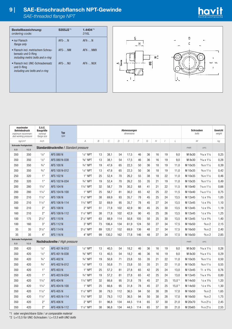
Bestellbezeichnung:ordering code:
S355J2 *1
1.4404 *1
316L
• nur Flansch flange only
AFS-…N AFX-…N
• Flansch incl. metrischem Schrau-bensatz und O-Ring including metric bolts and o-ring
AFS-…NM AFX-…NMX
• Flansch incl. UNC-Schraubensatz und O-Ring including unc bolts and o-ring
AFS-…NU AFX-…NUX
9 | SAE-Einschraubflansch NPT-Gewinde SAE-threaded flange NPT
maximaler Betriebsdruck
maximum recommen-ded working pressure
S.A.E. Baugröße
nominal flange size
Typtype
Abmessungendimensions
Schraubenbolts
Gewichtweight
kg/cm² inch A B C D E F G H I L M kg
Schraube Festigkeitskl.Standarddruckreihe / Standard pressure metr. unc.
8.8 10.9
350 350 ¹ ⁄₂" AFS 080 N ¹ ⁄₂" NPT 13 38,1 54 17,5 46 36 16 19 9,0 M 8x30 ⁵⁄₁₆ x 1¹⁄₄ 0,25
350 350 ¹ ⁄₂" AFS 080 N-038 ³⁄₈" NPT 13 38,1 54 17,5 46 36 16 19 9,0 M 8x30 ⁵⁄₁₆ x 1¹⁄₄ 0,28
350 350 ³⁄₄" AFS 100 N ³⁄₄" NPT 19 47,6 65 22,3 50 36 18 19 11,0 M 10x35 ³⁄₈ x 1¹ ⁄₂ 0,39
350 350 ³⁄₄" AFS 100 N-012 ¹ ⁄₂" NPT 13 47,6 65 22,3 50 36 18 19 11,0 M 10x35 ³⁄₈ x 1¹ ⁄₂ 0,42
250 320 1" AFS 102 N 1" NPT 25 52,4 70 26,2 55 38 18 22 11,0 M 10x35 ³⁄₈ x 1¹ ⁄₂ 0,46
250 320 1" AFS 102 N-034 ³⁄₄" NPT 19 52,4 70 26,2 55 35 21 19 11,0 M 10x35 ³⁄₈ x 1¹ ⁄₂ 0,49
200 280 1¹⁄₄" AFS 104 N 1¹⁄₄" NPT 32 58,7 79 30,2 68 41 21 22 11,5 M 10x40 ⁷⁄₁₆ x 1¹ ⁄₂ 0,66
200 280 1¹⁄₄" AFS 104 N-100 1" NPT 25 58,7 81 30,2 65 42 25 22 11,5 M 10x40 ⁷⁄₁₆ x 1¹ ⁄₂ 0,75
200 210 1¹ ⁄₂" AFS 106 N 1¹ ⁄₂" NPT 38 69,9 93 35,7 78 45 25 24 13,5 M 12x45 ¹ ⁄₂ x 1³⁄₄ 1,05
200 210 1¹ ⁄₂" AFS 106 N-114 1¹⁄₄" NPT 32 69,9 95 35,7 78 45 27 24 13,5 M 12x45 ¹ ⁄₂ x 1³⁄₄ 1,10
160 210 2" AFS 108 N 2" NPT 51 77,8 102 42,9 90 45 25 30 13,5 M 12x45 ¹ ⁄₂ x 1³⁄₄ 1,19
160 210 2" AFS 108 N-112 1¹ ⁄₂" NPT 38 77,8 102 42,9 90 45 25 26 13,5 M 12x45 ¹ ⁄₂ x 1³⁄₄ 1,25
100 175 2¹ ⁄₂" AFS 110 N 2¹ ⁄₂" NPT 63 88,9 114 50,8 105 50 25 30 13,5 M 12x45 ¹ ⁄₂ x 1³⁄₄ 1,40
100 160 3" AFS 112 N 3" NPT 73 106,4 134 61,9 124 50 27 34 17,5 M 16x50 ⁵⁄₈ x 2 2,15
35 35 3¹ ⁄₂" AFS 114 N 3¹ ⁄₂" NPT 89 120,7 152 69,9 136 48 27 34 17,5 M 16x50 ⁵⁄₈ x 2 2,40
35 35 4" AFS 116 N 4" NPT 99 130,2 162 77,8 146 48 27 34 17,5 M 16x50 ⁵⁄₈ x 2 2,85Schraube Festigkeitskl.
Hochdruckreihe / High pressure metr. unc.8.8 10.9
350 420 ¹ ⁄₂" AFS 401 N-012 ¹ ⁄₂" NPT 13 40,5 54 18,2 46 36 16 19 9,0 M 8x30 ⁵⁄₁₆ x 1¹⁄₄ 0,26
350 420 ¹ ⁄₂" AFS 401 N-038 ³⁄₈" NPT 13 40,5 54 18,2 46 36 16 19 9,0 M 8x30 ⁵⁄₁₆ x 1¹⁄₄ 0,29
350 420 ³⁄₄" AFS 402 N ³⁄₄" NPT 19 50,8 71 23,8 55 35 21 22 11,0 M 10x35 ³⁄₈ x 1¹ ⁄₂ 0,50
350 420 ³⁄₄" AFS 402 N-012 ¹ ⁄₂" NPT 13 50,8 71 23,8 55 35 21 22 11,0 M 10x35 ³⁄₈ x 1¹ ⁄₂ 0,55
350 420 1" AFS 403 N 1" NPT 25 57,2 81 27,8 65 42 25 24 13,0 M 12x45 ⁷⁄₁₆ x 1³⁄₄ 0,76
350 420 1" AFS 403 N-034 ³⁄₄" NPT 19 57,2 81 27,8 65 42 25 24 13,0 M 12x45 ⁷⁄₁₆ x 1³⁄₄ 0,80
350 420 1¹⁄₄" AFS 404 N 1¹⁄₄" NPT 32 66,6 95 31,8 78 45 27 25 15,0 *2 M 14x50 ¹ ⁄₂ x 1³⁄₄ 1,20
350 420 1¹⁄₄" AFS 404 N-100 1" NPT 25 66,6 95 31,8 78 45 27 25 15,0 *2 M 14x50 ¹ ⁄₂ x 1³⁄₄ 1,30
350 420 1¹ ⁄₂" AFS 405 N 1¹ ⁄₂" NPT 38 79,3 112 36,5 94 50 30 28 17,0 M 16x50 ⁵⁄₈ x 2 1,65
350 420 1¹ ⁄₂" AFS 405 N-114 1¹⁄₄" NPT 32 79,3 112 36,5 94 50 30 28 17,0 M 16x50 ⁵⁄₈ x 2 1,75
350 420 2" AFS 406 N 2" NPT 51 96,8 134 44,5 114 65 37 30 21,0 M 20x70 ³⁄₄ x 2¹ ⁄₂ 2,45
350 420 2" AFS 406 N-112 1¹ ⁄₂" NPT 38 96,8 134 44,5 114 65 37 30 21,0 M 20x65 ³⁄₄ x 2¹ ⁄₂ 2,55

10 |
Bestellbezeichnung:ordering code:
S355J2 *1
1.4404 *1
316L
• Flansch mit metrischen Gewinden flange with metric threads
GFS-…NM GFX-…NM
• Flansch mit UNC-Gewinden flange with UNC threads
GFS-…NU GFX-…NU
*1 oder vergleichbare Güte / or comparable material
10 | SAE-Einschraub-Gegenflansch NPT-Gewinde SAE-threaded flange NPT-companion
maximaler Betriebsdruck
maximum recommen-ded working pressure
S.A.E. Baugröße
nominal flange size
Typtype
Abmessungendimensions
Gewindethread
Gewichtweight
kg/cm² inch A B C D E F G H I M kg
Schraube Festigkeitskl.Standarddruckreihe / Standard pressure metr. unc.
8.8 10.9
350 350 ¹ ⁄₂" GFS 080 N ¹⁄₂" NPT 13 38,1 54 17,5 46 36 16 19 M 8 ⁵⁄₁₆ 0,25
350 350 ¹ ⁄₂" GFS 080 N-038 ³⁄₈" NPT 13 38,1 54 17,5 46 36 16 19 M 8 ⁵⁄₁₆ 0,28
350 350 ³⁄₄" GFS 100 N ³⁄₄" NPT 19 47,6 65 22,3 50 36 18 19 M 10 ³⁄₈ 0,39
350 350 ³⁄₄" GFS 100 N-012 ¹⁄₂" NPT 13 47,6 65 22,3 50 36 18 19 M 10 ³⁄₈ 0,42
250 320 1" GFS 102 N 1" NPT 25 52,4 70 26,2 55 38 18 22 M 10 ³⁄₈ 0,46
250 320 1" GFS 102 N-034 ³⁄₄" NPT 19 52,4 70 26,2 55 35 21 19 M 10 ³⁄₈ 0,49
200 280 1¹⁄₄" GFS 104 N 1¹⁄₄" NPT 32 58,7 79 30,2 68 41 21 22 M 10 ⁷⁄₁₆ 0,66
200 280 1¹⁄₄" GFS 104 N-100 1" NPT 25 58,7 81 30,2 65 42 25 22 M 10 ⁷⁄₁₆ 0,75
200 210 1¹ ⁄₂" GFS 106 N 1¹⁄₂" NPT 38 69,9 93 35,7 78 45 25 24 M 12 ¹⁄₂ 1,05
200 210 1¹ ⁄₂" GFS 106 N-114 1¹⁄₄" NPT 32 69,9 95 35,7 78 45 27 24 M 12 ¹⁄₂ 1,10
160 210 2" GFS 108 N 2" NPT 51 77,8 102 42,9 90 45 25 30 M 12 ¹⁄₂ 1,19
160 210 2" GFS 108 N-112 1¹⁄₂" NPT 38 77,8 102 42,9 90 45 25 26 M 12 ¹⁄₂ 1,25
100 175 2¹ ⁄₂" GFS 110 N 2¹⁄₂" NPT 63 88,9 114 50,8 105 50 25 30 M 12 ¹⁄₂ 1,40
100 160 3" GFS 112 N 3" NPT 73 106,4 134 61,9 124 50 27 34 M 16 ⁵⁄₈ 2,15
35 35 3¹ ⁄₂" GFS 114 N 3¹⁄₂" NPT 89 120,7 152 69,9 136 48 27 34 M 16 ⁵⁄₈ 2,40
35 35 4" GFS 116 N 4" NPT 99 130,2 162 77,8 146 48 27 34 M 16 ⁵⁄₈ 2,85Schraube Festigkeitskl.
Hochdruckreihe / High pressure metr. unc.8.8 10.9
350 420 ¹ ⁄₂" GFS 401 N-012 ¹⁄₂" NPT 13 40,5 54 18,2 46 36 16 19 M 8 ⁵⁄₁₆ 0,26
350 420 ¹ ⁄₂" GFS 401 N-038 ³⁄₈" NPT 13 40,5 54 18,2 46 36 16 19 M 8 ⁵⁄₁₆ 0,29
350 420 ³⁄₄" GFS 402 N ³⁄₄" NPT 19 50,8 71 23,8 55 35 21 22 M 10 ³⁄₈ 0,50
350 420 ³⁄₄" GFS 402 N-012 ¹⁄₂" NPT 13 50,8 71 23,8 55 35 21 22 M 10 ³⁄₈ 0,55
350 420 1" GFS 403 N 1" NPT 25 57,2 81 27,8 65 42 25 24 M 12 ⁷⁄₁₆ 0,76
350 420 1" GFS 403 N-034 ³⁄₄" NPT 19 57,2 81 27,8 65 42 25 24 M 12 ⁷⁄₁₆ 0,80
350 420 1¹⁄₄" GFS 404 N 1¹⁄₄" NPT 32 66,6 95 31,8 78 45 27 25 M 14 ¹⁄₂ 1,20
350 420 1¹⁄₄" GFS 404 N-100 1" NPT 25 66,6 95 31,8 78 45 27 25 M 14 ¹⁄₂ 1,30
350 420 1¹ ⁄₂" GFS 405 N 1¹⁄₂" NPT 38 79,3 112 36,5 94 50 30 28 M 16 ⁵⁄₈ 1,65
350 420 1¹ ⁄₂" GFS 405 N-114 1¹⁄₄" NPT 32 79,3 112 36,5 94 50 30 28 M 16 ⁵⁄₈ 1,75
350 420 2" GFS 406 N 2" NPT 51 96,8 134 44,5 114 65 37 30 M 20 ³⁄₄ 2,45
350 420 2" GFS 406 N -112 1¹⁄₂" NPT 38 96,8 134 44,5 114 65 37 30 M 20 ³⁄₄ 2,55

*1 oder vergleichbare Güte / or comparable material*2 L=13,5 für UNC-Schrauben / L=13.5 with UNC-bolts
Bestellbezeichnung:ordering code:
S355J2 *1
1.4404 *1
316L
• nur Flansch flange only
AFS-…T AFX-…T
• incl. metrischem Schrauben satz und O-Ring including metric bolts and o-ring
AFS-…TM AFX-…TMX
• incl. UNC Schraubensatz und O-Ring including UNC bolts and o-ring
AFS-…TU AFX-…TUX
11 | SAE-Einschraubflansch UN/UNF Gewinde SAE-threaded flange UN/UNF
maximaler Betriebsdruck
maximum recommen-ded working pressure
S.A.E. Baugröße
nominal flange size
Typtype
Abmessungendimensions
Schraubenbolts
Gewichtweight
kg/cm² inch A B C D E F G H I L U K Z M kg
Schraube Festigkeitskl.Standarddruckreihe / Standard pressure metr. unc.
8.8 10.9
350 350 ¹ ⁄₂" AFS 080 T ³⁄₄"-16UNF 13 38,1 54 17,5 46 36 16 17 9,0 20,6 2,5 15° M 8x30 ⁵⁄₁₆ x 1¹⁄₄ 0,25
350 350 ³⁄₄" AFS 100 T 1¹⁄₁₆"-12UN 19 47,6 65 22,3 50 36 18 23 11,0 29,2 3,3 15° M 10x35 ³⁄₈x 1¹ ⁄₂ 0,39
250 320 1" AFS 102 T 1⁵⁄₁₆"-12UN 25 52,4 70 26,2 55 38 18 23 11,0 35,5 3,3 15° M 10x35 ³⁄₈x 1¹ ⁄₂ 0,46
200 280 1¹⁄₄" AFS 104 T 1⁵⁄₈"-12UN 32 58,7 79 30,2 68 41 21 23 11,5 43,5 3,3 15° M 10x40 ⁷⁄₁₆ x 1¹ ⁄₂ 0,66
200 210 1¹ ⁄₂" AFS 106 T 1⁷⁄₈"-12UN 38 69,9 93 35,7 78 45 25 23 13,5 49,8 3,3 15° M 12x45 ¹ ⁄₂ x 1³⁄₄ 1,05Schraube Festigkeitskl.
Hochdruckreihe / High pressure metr. unc.8.8 10.9
350 420 ¹ ⁄₂" AFS 401 T ³⁄₄"-16UNF 13 40,5 54 18,2 46 36 16 17 9,0 20.6 2,5 15° M 8x30 ⁵⁄₁₆ x 1¹⁄₄ 0,26
350 420 ³⁄₄" AFS 402 T 1¹⁄₁₆"-12UN 19 50,8 71 23,8 55 35 21 23 11,0 29,3 3,3 15° M 10x35 ³⁄₈ x 1¹ ⁄₂ 0,50
350 420 1" AFS 403 T 1⁵⁄₁₆"-12UN 25 57,2 81 27,8 65 42 25 23 13,0 35,5 3,3 15° M 12x45 ⁷⁄₁₆ x 1¹ ⁄₂ 0,76
350 420 1¹⁄₄" AFS 404 T 1⁵⁄₈"-12UN 32 66,6 95 31,8 78 45 27 23 15,0 *2 43,5 3,3 15° M 14x50 ¹ ⁄₂ x 1³⁄₄ 1,20
350 420 1¹ ⁄₂" AFS 405 T 1⁷⁄₈"-12UN 38 79,3 112 36,5 94 50 30 23 17,0 49,8 3,3 15° M 16x50 ⁵⁄₈ x 2 1,65

12 |
*1 oder vergleichbare Güte / or comparable material*2 L=13,5 für UNC-Schrauben / L=13.5 with UNC-bolts
Hinweis: Der angegebene Nenndruck ist nach der SAE J 518 C durch den Flansch bzw. nach der Verschraubung nach DIN 3861 festgelegt. / Please note: The maximum working pressure is fixed by SAE J 518 C on flange side or by the thread side to DIN 3861.
Bestellbezeichnung:ordering code:
S355J2 *1
• nur Flansch flange only
AFG-…
• incl. metrischem Schraubensatz und O-Ring including metric bolts and o-ring
AFG-…M
• incl. UNC-Schraubensatz und O-Ring including UNC bolts and o-ring
AFG-…U
• incl. Schraubensatz (metrisch oder UNC), O-Ring, Schneidring und Mutter including bolts (metr. or UNC), o-ring, cutting ring and nut
AFG-…MM (UM)
12 | SAE-Außengewindeflansch 24° DIN 3901 SAE-flange metric tapped 24° DIN 3901
maximaler Betriebsdruck
maximum recommen-ded working pressure
S.A.E. Baugröße
nominal flange size
Typtype
Abmessungendimensions
Schraubenbolts
Gewichtweight
kg/cm² inch A B C D E F G H I L M kg
Schraube Festigkeitskl.Standarddruckreihe / Standard pressure metr. unc.
8.8 10.9
315 315 ¹ ⁄₂" AFG 080 M/L 15 M 22x1,5 12 38,1 54 17,5 46 52 13 7,0 9,0 M 8x25 ⁵⁄₁₆ x 1¹⁄₄ 0,25
315 315 ¹ ⁄₂" AFG 080 M/S 16 M 24x1,5 12 38,1 54 17,5 46 52 13 8,5 9,0 M 8x25 ⁵⁄₁₆ x 1¹⁄₄ 0,25
160 160 ³⁄₄" AFG 100 M/L 22 M 30x2 19 47,6 65 22,3 50 60 14 7,5 11,5 M 10x30 ³⁄₈ x 1¹⁄₄ 0,35
345 345 ³⁄₄" AFG 100 M/S 20 M 30x2 16 47,6 65 22,3 50 60 14 10,5 11,5 M 10x30 ³⁄₈ x 1¹⁄₄ 0,36
160 160 1" AFG 102 M/L 22 M 30x2 19 52,4 70 26,2 55 63 16 7,5 11,5 M 10x30 ³⁄₈ x 1¹⁄₄ 0,44
160 160 1" AFG 102 M/L 28 M 36x2 24 52,4 70 26,2 55 63 16 7,5 11,5 M 10x30 ³⁄₈ x 1¹⁄₄ 0,50
250 320 1" AFG 102 M/S 20 M 30x2 16 52,4 70 26,2 55 63 16 10,5 11,5 M 10x30 ³⁄₈ x 1¹⁄₄ 0,46
250 320 1" AFG 102 M/S 25 M 36x2 20 52,4 70 26,2 55 63 16 12,0 11,5 M 10x30 ³⁄₈ x 1¹⁄₄ 0,52
160 160 1¹⁄₄" AFG 104 M/L 28 M 36x2 24 58,7 79 30,2 68 65 14 7,5 11,5 M 10x30 ⁷⁄₁₆ x 1¹ ⁄₂ 0,68
160 160 1¹⁄₄" AFG 104 M/L 35 M 45x2 29 58,7 79 30,2 68 65 14 10,5 11,5 M 10x30 ⁷⁄₁₆ x 1¹ ⁄₂ 0,72
200 280 1¹⁄₄" AFG 104 M/S 30 M 42x2 25 58,7 79 30,2 68 65 14 13,5 11,5 M 10x30 ⁷⁄₁₆ x 1¹ ⁄₂ 0,70
160 160 1¹ ⁄₂" AFG 106 M/L 42 M 52x2 36 69,9 94 35,7 78 70 16 11,0 13,5 M 12x35 ¹ ⁄₂ x 1¹ ⁄₂ 1,00
200 210 1¹ ⁄₂" AFG 106 M/S 38 M 52x2 32 69,9 94 35,7 78 70 16 16,0 13,5 M 12x35 ¹ ⁄₂ x 1¹ ⁄₂ 1,02
160 210 2" AFG 108 M/L 42 - H 74 M 52x2 36 77,8 102 42,9 90 74 25 11,0 13,5 M 12x45 ¹ ⁄₂ x 1³⁄₄ 1,81
160 210 2" AFG 108 M/S 38 - H 74 M 52x2 32 77,8 102 42,9 90 74 25 16,0 13,5 M 12x45 ¹ ⁄₂ x 1³⁄₄ 1,92Schraube Festigkeitskl.
Hochdruckreihe / High pressure metr. unc.8.8 10.9
350 420 ¹ ⁄₂" AFG 401 M/S 16 M 24x1,5 12 40,5 56 18,2 48 47 16 8,5 9,0 M 8x30 ⁵⁄₁₆ x 1¹⁄₄ 0,30
350 420 ³⁄₄" AFG 402 M/S 16-50 M 24x1,5 12 50,8 71 23,8 50 52 19 8,5 11,5 M 10x35 ³⁄₈ x 1¹ ⁄₂ –
350 420 ³⁄₄" AFG 402 M/S 20-50 M 30x2 16 50,8 71 23,8 50 52 19 10,5 11,5 M 10x35 ³⁄₈ x 1¹ ⁄₂ –
350 420 ³⁄₄" AFG 402 M/S 25-50 M 36x2 18 50,8 71 23,8 50 52 19 12,0 11,5 M 10x35 ³⁄₈ x 1¹ ⁄₂ –
350 420 ³⁄₄" AFG 402 M/S 25 M 36x2 19 50,8 71 23,8 60 73 19 12,0 11,5 M 10x35 ³⁄₈ x 1¹ ⁄₂ 0,68
350 420 1" AFG 403 M/S 20-60 M 30x2 16 57,2 81 27,8 70 60 24 10,5 13,0 M 12x45 ⁷⁄₁₆ x 1³⁄₄ –
350 420 1" AFG 403 M/S 25 M 36x2 19/26 57,2 81 27,8 70 82 24 12,0 13,0 M 12x45 ⁷⁄₁₆ x 1³⁄₄ 1,17
350 420 1" AFG 403 M/S 30 M 42x2 25 57,2 81 27,8 70 82 24 13,5 13,0 M 12x45 ⁷⁄₁₆ x 1³⁄₄ 1,00
350 420 1¹⁄₄" AFG 404 M/S 30 M 42x2 25 66,6 95 31,8 78 92 27 13,5 15,0 *2 M 14x50 ¹ ⁄₂ x 1³⁄₄ 1,54
350 420 1¹⁄₄" AFG 404 M/S 30-68 M 42x2 25 66,6 95 31,8 78 68 27 13,5 15,0 *2 M 14x50 ¹ ⁄₂ x 1³⁄₄ –
350 420 1¹⁄₄" AFG 404 M/S 38 M 52x2 29 66,6 95 31,8 78 92 27 16,0 15,0 *2 M 14x50 ¹ ⁄₂ x 1³⁄₄ 1,60
350 420 1¹⁄₄" AFG 404 M/S 38-60 M 52x2 28 66,6 95 31,8 78 60 24 16,0 15,0 *2 M 14x50 ¹ ⁄₂ x 1³⁄₄ –
350 420 1¹ ⁄₂" AFG 405 M/S 38 M 52x2 32 79,3 113 36,5 95 96 30 16,0 17,5 M 16x55 ⁵⁄₈ x 2 2,20
DIN 3901 Bohrungsform W / Drill form W

13 |
Bestellbezeichnung:ordering code:
S355J2G3 1
1.4404 1
316L
• nur Flansch flange only
GFG-…M/…
Bestellbezeichnung:ordering code:
S355J2 *1
1.4404 *1
316L
• Flansch mit metrischen Gewinden flange with metric threads
GFG-…L/S…
13 | SAE-Außengewinde-Gegenflansch 24° DIN 3901 SAE-flange metric tapped 24° companion DIN 3901
maximaler Betriebsdruck
maximum recommen-ded working pressure
S.A.E. Baugröße
nominal flange size
Typtype
Abmessungendimensions
Gewindethread
Gewichtweight
kg/cm² inch A B C D E F G H I M kg
Schraube Festigkeitskl.Standarddruckreihe / Standard pressure metr. unc.
8.8 10.9
315 315 ¹ ⁄₂" GFG-080M/L15 M22x1,5 12,0 38,1 54,0 17,5 46,0 36,0 13,0 7,0 M8 ⁵⁄₁₆ 0,23
350 350 ¹ ⁄₂" GFG-080M/S16 M24x1,5 12,0 38,1 54,0 17,5 46,0 36,0 13,0 8,5 M8 ⁵⁄₁₆ 0,24
160 160 ³⁄₄" GFG-100M/L22 M30x2 19,0 47,6 65,0 22,3 50,0 36,0 14,0 7,5 M10 ³⁄₈ 0,33
345 345 ³⁄₄" GFG-100M/S20 M30x2 16,0 47,6 65,0 22,3 50,0 36,0 14,0 10,5 M10 ³⁄₈ 0,35
160 160 1" GFG-102M/L22 M30x2 19,0 52,4 70,0 26,2 55,0 38,0 16,0 7,5 M10 ³⁄₈ 0,43
160 160 1" GFG-102M/L28 M36x2 24,0 52,4 70,0 26,2 55,0 38,0 16,0 7,5 M10 ³⁄₈ 0,43
250 320 1" GFG-102M/S20 M30x2 16/25 52,4 70,0 26,2 55,0 38,0 16,0 10,5 M10 ³⁄₈ 0,44
250 320 1" GFG-102M/S25 M36x2 20/25 52,4 70,0 26,2 55,0 38,0 16,0 12,0 M10 ³⁄₈ 0,46
160 160 1¹⁄₄" GFG-104M/L28 M36x2 24,0 58,7 79,0 30,2 68,0 41,0 14,0 7,5 M10 ⁷⁄₁₆ 0,53
160 160 1¹⁄₄" GFG-104M/L35 M45x2 29,0 58,7 79,0 30,2 68,0 41,0 14,0 10,5 M10 ⁷⁄₁₆ 0,56
200 280 1¹⁄₄" GFG-104M/S30 M42x2 25,0 58,7 79,0 30,2 68,0 41,0 14,0 13,5 M10 ⁷⁄₁₆ 0,58
160 160 1¹ ⁄₂" GFG-106M/L42 M52x2 36,0 69,9 93,0 35,7 78,0 45,0 16,0 11,0 M12 ¹ ⁄₂ 0,83
200 210 1¹ ⁄₂" GFG-106M/S38 M52x2 32/36 69,9 93,0 35,7 78,0 45,0 16,0 16,0 M12 ¹ ⁄₂ 0,89Schraube Festigkeitskl.
Hochdruckreihe / High pressure metr. unc.8.8 10.9
350 420 ¹ ⁄₂" GFG-401M/S16 M24x1,5 12,0 40,5 54,0 18,2 46,0 36,0 16,0 8,5 M8 ⁵⁄₁₆ 0,27
350 420 ³⁄₄" GFG-402M/S16 M24x1,5 12,0 50,8 70,0 23,8 55,0 38,0 19,0 8,5 M10 ³⁄₈ 0,50
350 420 ³⁄₄" GFG-402M/S20 M30x2 16,0 50,8 70,0 23,8 55,0 38,0 19,0 10,5 M10 ³⁄₈ 0,51
350 420 ³⁄₄" GFG-402M/S25 M36x2 19,0 50,8 70,0 23,8 55,0 40,0 19,0 12,0 M10 ³⁄₈ 0,53
350 420 1" GFG-403M/S20 M30x2 16,0 57,2 81,0 27,8 65,0 42,0 24,0 10,5 M12 ⁷⁄₁₆ 0,82
350 420 1" GFG-403M/S30 M42x2 25,0 57,2 81,0 27,8 65,0 42,0 23,0 13,5 M12 ⁷⁄₁₆ 0,78
350 420 1¹⁄₄" GFG-404M/S30 M42x2 25,0 66,6 95,0 31,8 78,0 60,0 24,0 13,5 M14 ¹ ⁄₂ 1,23
350 420 1¹⁄₄" GFG-404M/S38 M52x2 29,0 66,6 95,0 31,8 78,0 60,0 24,0 16,0 M14 ¹ ⁄₂ 1,32
350 420 1¹ ⁄₂" GFG-405M/S38 M52x2 32,0 79,3 112,0 36,5 94,0 55,0 30,0 16,0 M16 ⁵⁄₈ 1,96
*1 oder vergleichbare Güte / or comparable material
CD
E F
MI
24°
nBA
Gewind
e
HG

14 | SAE-Außengewinde Adapter-24° DIN 3901 SAE-flange adapter metric 24° DIN 3901
Bestellbezeichnung:ordering code:
S355J2 *1
C221.4404 *1
316L
• nur Zwischenstück adaptor only
SFCE-… SFCE-X-…
• incl. Flanschhälften, metrischem Schraubensatz und O-Ring (Mutter und Schneidring) including split flanges, metric bolts and o-ring (nut and cutting ring)
SFCE-…M(M) SFCE-X-…MX(M)
• incl. Flanschhälften, UNC-Schraubensatz und O-Ring (Mutter und Schneidring) including split flanges, UNC bolts and o-ring (nut and cutting ring)
SFCE-…U(M) SFCE-X-…UX(M)
DIN 3901 Bohrungsform W / Drill form W
maximaler Betriebsdruck
maximum recommen-ded working pressure
S.A.E. Baugröße
nominal flange size
Typtype
Abmessungendimensions
Schraubenbolts
Gewichtweight
kg/cm² inch A A1 B C D E F G I L SW M kg
Schraube Festigkeitskl.Standarddruckreihe / Standard pressure metr. unc.
8.8 10.9
315 315 ¹ ⁄₂" SFCE 3001/L15 M 22x1,5 30,2 12 38,1 54 17,5 46 48,2 7,0 8,75 24 M 8x25 ⁵⁄₁₆ x 1¹⁄₄ 0,29
350 350 ¹ ⁄₂" SFCE 3001/S16 M 24x1,5 30,2 12 38,1 54 17,5 46 50,2 8,5 8,75 24 M 8x25 ⁵⁄₁₆ x 1¹⁄₄ 0,32
315 315 ³⁄₄" SFCE 3002/L18 M 26x1,5 38,1 15/17 47,6 65 22,3 52 53,2 7,5 10,75 30 M 10x30 ³⁄₈ x 1¹ ⁄₂ 0,55
160 160 ³⁄₄" SFCE 3002/L22 M 30x2 38,1 19 47,6 65 22,3 52 53,2 7,5 10,75 30 M 10x30 ³⁄₈ x 1¹ ⁄₂ 0,56
160 160 ³⁄₄" SFCE 3002/L28 M 36x2 38,1 19 47,6 65 22,3 52 53,2 7,5 10,75 30 M 10x30 ³⁄₈ x 1¹ ⁄₂ 0,75
350 350 ³⁄₄" SFCE 3002/S20 M 30x2 38,1 16/17 47,6 65 22,3 52 57,2 10,5 10,75 30 M 10x30 ³⁄₈ x 1¹ ⁄₂ 0,63
350 350 ³⁄₄" SFCE 3002/S25 M 36x2 38,1 17 47,6 65 22,3 52 57,2 12,0 10,75 30 M 10x30 ³⁄₈ x 1¹ ⁄₂ 0,76
160 160 1" SFCE 3003/L28 M 36x2 44,5 24 52,4 70 26,2 59 54,2 7,5 10,75 36 M 10x30 ³⁄₈ x 1¹ ⁄₂ 0,69
250 320 1" SFCE 3003/S25 M 36x2 44,5 20 52,4 70 26,2 59 58,2 12,0 10,75 36 M 10x30 ³⁄₈ x 1¹ ⁄₂ 0,78
250 320 1" SFCE 3003/S30 M 42x2 44,5 24 52,4 70 26,2 59 63,2 13,5 10,75 36 M 10x30 ³⁄₈ x 1¹ ⁄₂ 0,91
160 160 1¹⁄₄" SFCE 3004/L28 M 36x2 50,8 24/27 58,7 79 30,2 73 58,2 7,5 *2 36 *3 ⁷⁄₁₆ x 1¹ ⁄₂ 1,05
160 160 1¹⁄₄" SFCE 3004/L35 M 45x2 50,8 30/32 58,7 79 30,2 73 58,2 10,5 *2 41 *3 ⁷⁄₁₆ x 1¹ ⁄₂ 1,10
200 280 1¹⁄₄" SFCE 3004/S25 M 36x2 50,8 20/27 58,7 79 30,2 73 60,2 12,0 *2 41 *3 ⁷⁄₁₆ x 1¹ ⁄₂ 1,17
200 280 1¹⁄₄" SFCE 3004/S30 M 42x2 50,8 25/28 58,7 79 30,2 73 62,2 13,5 *2 41 *3 ⁷⁄₁₆ x 1¹ ⁄₂ 1,19
200 280 1¹⁄₄" SFCE 3004/S38 M 52x2 50,8 28 58,7 79 30,2 73 66,2 16,0 *2 46 *3 ⁷⁄₁₆ x 1¹ ⁄₂ 1,39
160 160 1¹ ⁄₂" SFCE 3005/L42 M 52x2 60,3 36 69,9 94 35,7 83 64,2 11,0 13,50 46 M 12x35 ¹ ⁄₂ x 1¹ ⁄₂ 1,34
200 210 1¹ ⁄₂" SFCE 3005/S38 M 52x2 60,3 32 69,9 94 35,7 83 70,2 16,0 13,50 46 M 12x35 ¹ ⁄₂ x 1¹ ⁄₂ 1,50
Oberfläche: CR-6: auslaufend/Neu: CR-6 frei / surface: CR-6: phase-out/New: CR-6 free*1 oder vergleichbare Güte / or comparable material
*2 wahlweise 10,75 oder 12,75 / choice of 10.75 or 12.75 *3 wahlweise M 10x30 oder M 12x35 / choice of M 10x30 or M 12x35

*1 oder vergleichbare Güte / or comparable material*2 wahlweise 12,0 oder 13,0 / choice of 12.0 or 13.0 *3 wahlweise 13,5 oder 14,75 / choice of 13.5 or 14.75
Hinweis: Der angegebene Nenndruck ist nach der SAE J 518 C durch den Flansch bzw. nach der Verschraubung nach DIN 3861 festgelegt. / Please note: The maximum working pressure is fixed by SAE J 518 C on flange side or by the thread side to DIN 3861.
Bestellbezeichnung:ordering code:
S355J2 *1
C221.4404 *1
316L
• nur Zwischenstück adaptor only
SFCE-… SFCE-X-…
• incl. Flanschhälften, metrischem Schraubensatz und O-Ring (Mutter und Schneidring) including split flanges, metric bolts and o-ring (nut and cutting ring)
SFCE-…M(M) SFCE-X-…MX(M)
• incl. Flanschhälften, UNC-Schraubensatz und O-Ring (Mutter und Schneidring) including split flanges, UNC bolts and o-ring (nut and cutting ring)
SFCE-…U(M) SFCE-X-…UX(M)
15 | SAE-Außengewinde Adapter-24° DIN 3901 SAE-flange adapter metric 24° DIN 3901
DIN 3901 Bohrungsform W / Drill form W
maximaler Betriebsdruck
maximum recommen-ded working pressure
S.A.E. Baugröße
nominal flange size
Typtype
Abmessungendimensions
Schraubenbolts
Gewichtweight
kg/cm² inch A A1 B C D E F G I L SW M kg
Schraube Festigkeitskl.Hochdruckreihe / High pressure metr. unc.
8.8 10.9
350 420 ¹ ⁄₂" SFCE 6001/S16 M 24x1,5 31,8 12 40,5 56 18,2 48 53,2 8,5 8,75 24 M 8x30 ⁵⁄₁₆ x 1¹⁄₄ 0,46
350 420 ³⁄₄" SFCE 6002/S16 M 24x1,5 41,3 12/17 50,8 71 23,8 60 59,2 8,5 10,75 30 M 10x35 ³⁄₈ x 1¹ ⁄₂ 0,78
350 420 ³⁄₄" SFCE 6002/S20 M 30x2 41,3 16 50,8 71 23,8 60 61,2 10,5 10,75 30 M 10x35 ³⁄₈ x 1¹ ⁄₂ 0,84
350 420 ³⁄₄" SFCE 6002/S25 M 36x2 41,3 17 50,8 71 23,8 60 63,2 12,0 10,75 30 M 10x35 ³⁄₈ x 1¹ ⁄₂ 0,96
350 420 ³⁄₄" SFCE 6002/S30 M 42x2 41,3 24/18 50,8 71 23,8 60 64,0 13,5 10,75 36 M 10x35 ³⁄₈ x 1¹ ⁄₂ 1,20
350 420 1" SFCE 6003/S25 M 36x2 47,6 20 57,2 81 27,8 70 72,2 12,0 *2 36 M 12x45 ⁷⁄₁₆ x 1³⁄₄ 1,42
350 420 1" SFCE 6003/S30 M 42x2 47,6 24 57,2 81 27,8 70 74,0 13,5 *2 36 M 12x45 ⁷⁄₁₆ x 1³⁄₄ 1,52
350 350 1" SFCE 6003/S38 M 52x2 47,6 24 57,2 81 27,8 70 90,0 16,0 *2 46 M 12x45 ⁷⁄₁₆ x 1³⁄₄ 1,42
350 420 1¹⁄₄" SFCE 6004/S30 M 42x2 54,0 25/30 66,6 95 31,8 78 79,2 13,5 *3 41 M 14x50 ¹ ⁄₂ x 1³⁄₄ 1,93
350 350 1¹⁄₄" SFCE 6004/S38 M 52x2 54,0 30 66,6 95 31,8 78 83,2 16,0 *3 46 M 14x50 ¹ ⁄₂ x 1³⁄₄ 2,08
350 350 1¹ ⁄₂" SFCE 6005/S38 M 52x2 63,5 30 79,3 113 36,5 95 89,2 16,0 17,00 46 M 16x55 ⁵⁄₈ x 2 3,03

*1 oder vergleichbare Güte / or comparable material*2 L=13,5 für UNC-Schrauben / L=13.5 with UNC-bolts
Bestellbezeichnung:ordering code:
S355J2 *1
• nur Flansch flange only
AFG-…
• incl. metrischem Schraubensatz und O-Ring including metric bolts and o-ring
AFG-…M
• incl. UNC-Schraubensatz und O-Ring including UNC bolts and o-ring
AFG-…U
16 | SAE-Außengewindeflansch JIC 37° SAE-threaded flange JIC 37°
maximaler Betriebsdruck
maximum recommen-ded working pressure
S.A.E. Baugröße
nominal flange size
Typtype
Abmessungendimensions
Schraubenbolts
Gewichtweight
kg/cm² inch A B C D E F G H L M kg
Schraube Festigkeitskl.Standarddruckreihe / Standard pressure metr. unc.
8.8 10.9
350 350 ¹ ⁄₂" AFG 080 JIC ³⁄₄ ³⁄₄" -16 JIC 9,9 38,1 54 17,5 46 52 13 9,0 M 8x30 ⁵⁄₁₆ x 1¹⁄₄ 0,25
350 350 ¹ ⁄₂" AFG 080 JIC ⁷⁄₈ ⁷⁄₈" -14 JIC 12,3 38,1 54 17,5 46 52 13 9,0 M 8x30 ³⁄₈ x 1¹⁄₄ 0,30
350 350 ³⁄₄" AFG 100 JIC 1¹⁄₁₆ 1¹⁄₁₆" -12 JIC 15,5 47,6 65 22,3 50 60 14 11,5 M 10x30 ³⁄₈ x 1¹⁄₄ 0,35
250 320 1" AFG 102 JIC 1⁵⁄₁₆ 1⁵⁄₁₆" -12 JIC 21,5 52,4 70 26,2 55 63 16 11,5 M 10x30 ³⁄₈ x 1¹⁄₄ 0,50
200 280 1¹⁄₄" AFG 104 JIC 1⁵⁄₈ 1⁵⁄₈" -12 JIC 27,5 58,7 79 30,2 68 65 14 11,5 M 10x30 ⁷⁄₁₆ x 1¹ ⁄₂ 0,70
200 280 1¹⁄₄" AFG 104 JIC 1⁵⁄₁₆ 1⁵⁄₁₆" -12 JIC 21,5 58,7 79 30,2 68 65 14 11,5 M 10x30 ⁷⁄₁₆ x 1¹ ⁄₂ 0,70
200 210 1¹ ⁄₂" AFG 106 JIC 1⁷⁄₈ 1⁷⁄₈" -12 JIC 33,0 69,9 94 35,7 78 70 16 13,5 M 12x35 ¹ ⁄₂ x 1¹ ⁄₂ 1,00Schraube Festigkeitskl.
Hochdruckreihe / High pressure metr. unc.8.8 10.9
350 420 ¹ ⁄₂" AFG 401 JIC ³⁄₄ ³⁄₄" -16 JIC 9,9 40,5 56 18,2 48 60 16 9,0 M 8x30 ⁵⁄₁₆ x 1¹⁄₄ 0,30
350 420 ¹ ⁄₂" AFG 401 JIC ⁷⁄₈ ⁷⁄₈" -14 JIC 12,3 40,5 56 18,2 48 60 16 9,0 M 8x30 ⁵⁄₁₆ x 1¹⁄₄ 0,40
350 420 ³⁄₄" AFG 402 JIC 1¹⁄₁₆ 1¹⁄₁₆" -12 JIC 15,5 50,8 71 23,8 60 73 19 11,5 M 10x35 ³⁄₈ x 1¹ ⁄₂ 0,70
350 420 1" AFG 403 JIC 1⁵⁄₁₆ 1⁵⁄₁₆" -12 JIC 21,5 57,2 81 27,8 70 82 24 13,0 M 12x45 ⁷⁄₁₆ x 1³⁄₄ 1,00
350 420 1¹⁄₄" AFG 404 JIC 1⁵⁄₈ 1⁵⁄₈" -12 JIC 27,5 66,6 95 31,8 78 92 27 15,0*2 M 14x50 ¹ ⁄₂ x 1³⁄₄ 1,50
350 420 1¹⁄₄" AFG 404 JIC 1⁵⁄₁₆ 1⁵⁄₁₆" -12 JIC 21,5 66,6 95 31,8 78 92 27 15,0*2 M 14x50 ¹ ⁄₂ x 1³⁄₄ 1,50
350 420 1¹ ⁄₂" AFG 405 JIC 1⁷⁄₈ 1⁷⁄₈" -12 JIC 33,0 79,3 113 36,5 95 96 30 17,5 M 16x55 ⁵⁄₈ x 2 2,30

Oberfläche: CR-6: auslaufend/Neu: CR-6 frei / surface: CR-6: phase-out/New: CR-6 free*1 oder vergleichbare Güte / or comparable material *2 wahlweise 10,75, 12,00 oder 12,75 / choice of 10.75, 12.00 or 12.75
*3 wahlweise M 10x30 oder M 12x35 / choice of M 10x30 or M 12x35*4 wahlweise 12,0 oder 13,0 / choice of 12.0 or 13.0 *5 wahlweise 13,5 oder 14,75 / choice of 13.5 or 14.75
Bestellbezeichnung:ordering code:
S355J2 *1
C221.4404 *1
316L
• nur Außengewindeflansch adaptor only
SFCE-…JIC SFCE-X-…JIC
• incl. Flanschhälften, metrischem Schraubensatz und O-Ring including split flanges, metric bolts and o-ring
SFCE-…JICM SFCE-X-…JICMX
• incl. Flanschhälften, UNC-Schraubensatz und O-Ring including split flanges, UNC bolts and o-ring
SFCE-…JICU SFCE-X-…JICUX
17 | SAE-Außengewinde Adapter JIC 37° SAE-adapter JIC 37°
maximaler Betriebsdruck
maximum recommen-ded working pressure
S.A.E. Baugröße
nominal flange size
Typtype
Abmessungendimensions
Schraubenbolts
Gewichtweight
kg/cm² inch A A1 B C D E F G L SW M kg
Schraube Festigkeitskl.Standarddruckreihe / Standard pressure metr. unc.
8.8 10.9
350 350 ¹ ⁄₂" SFCE 3001-JIC ⁷⁄₈ ⁷⁄₈" -14UN 30,2 12,3 38,1 54 17,5 46 48 8,75 20 M 8x25 ⁵⁄₁₆ x 1¹⁄₄ –
350 350 ³⁄₄" SFCE 3002-JIC1¹⁄₁₆ 1¹⁄₁₆" -12UN 38,1 15,5 47,6 65 22,3 52 55 10,75 30 M 10x30 ³⁄₈ x 1¹⁄₄ –
250 320 1" SFCE 3003-JIC1¹⁄₁₆ 1¹⁄₁₆" -12UN 44,5 15,5 52,4 70 26,2 59 55 10,75 36 M 10x30 ³⁄₈ x 1¹⁄₄ –
200 280 1¹⁄₄" SFCE 3004-JIC1⁵⁄₁₆ 1⁵⁄₁₆" -12UN 50,8 21,5 58,7 79 30,2 73 58 *2 42 *3 ⁷⁄₁₆ x 1¹ ⁄₂ –
200 280 1¹⁄₄" SFCE 3004-JIC1⁵⁄₈ 1⁵⁄₈" -12UN 50,8 27,5 58,7 79 30,2 73 58 *2 42 *3 ⁷⁄₁₆ x 1¹ ⁄₂ –
200 210 1¹ ⁄₂" SFCE 3005-JIC1⁷⁄₈ 1⁷⁄₈" -12UN 60,3 33,0 69,9 94 35,7 83 62 13,50 42 M 12x35 ¹ ⁄₂ x 1¹ ⁄₂ –Schraube Festigkeitskl.
Hochdruckreihe / High pressure metr. unc.8.8 10.9
350 350 ¹ ⁄₂" SFCE 6001-JIC1¹⁄₁₆ 1¹⁄₁₆" -12UN 31,8 15,5 40,5 56 18,2 48 50 8,75 20 M 8x30 ⁵⁄₁₆ x 1¹⁄₄ –
350 350 ¹ ⁄₂" SFCE 6001-JIC ⁷⁄₈ ⁷⁄₈" -14UN 31,8 12,3 40,5 56 18,2 48 50 8,75 20 M 8x30 ⁵⁄₁₆ x 1¹⁄₄ –
350 350 ¹ ⁄₂" SFCE 6001-JIC ³⁄₄ ³⁄₄" -16UN 31,8 9,9 40,5 56 18,2 48 50 8,75 20 M 8x30 ⁵⁄₁₆ x 1¹⁄₄ –
350 350 ³⁄₄" SFCE 6002-JIC1¹⁄₁₆ 1¹⁄₁₆" -12UN 41,3 15,5 50,8 71 23,8 60 64 10,75 30 M 10x35 ³⁄₈ x 1¹ ⁄₂ –
350 350 1" SFCE 6003-JIC1¹⁄₁₆ 1¹⁄₁₆" -12UN 47,6 15,5 57,2 81 27,8 70 72 *4 36 M 12x45 ⁷⁄₁₆ x 1¹ ⁄₂ –
350 350 1" SFCE 6003-JIC1⁵⁄₁₆ 1⁵⁄₁₆" -12UN 47,6 21,5 57,2 81 27,8 70 72 *4 36 M 12x45 ⁷⁄₁₆ x 1¹ ⁄₂ –
350 350 1¹⁄₄" SFCE 6004-JIC1⁵⁄₁₆ 1⁵⁄₁₆" -12UN 54,0 21,5 66,6 95 31,8 78 81 *5 41 M 14x50 ¹ ⁄₂ x 1³⁄₄ –
275 275 1¹⁄₄" SFCE 6004-JIC1⁵⁄₈ 1⁵⁄₈" -12UN 54,0 27,5 66,6 95 31,8 78 81 *5 41 M 14x50 ¹ ⁄₂ x 1³⁄₄ –
275 275 1¹ ⁄₂" SFCE 6005-JIC1⁵⁄₈ 1⁵⁄₈" -12UN 63,5 27,5 79,3 113 36,5 95 86 17,00 41 M 16x55 ⁵⁄₈ x 2 –
210 210 1¹ ⁄₂" SFCE 6005-JIC1⁷⁄₈ 1⁷⁄₈"-12UN 63,5 33,0 79,3 113 36,5 95 86 17,00 42 M 16x55 ⁵⁄₈ x 2 –
Oberfläche: CR-6: auslaufend/Neu: CR-6 frei / surface: CR-6: phase-out/New: CR-6 free*1 oder vergleichbare Güte / or comparable material *2 wahlweise 10,75, 12,00 oder 12,75 / choice of 10.75, 12.00 or 12.75
*3 wahlweise M 10x30 oder M 12x35 / choice of M 10x30 or M 12x35*4 wahlweise 12,0 oder 13,0 / choice of 12.0 or 13.0 *5 wahlweise 13,5 oder 14,75 / choice of 13.5 or 14.75
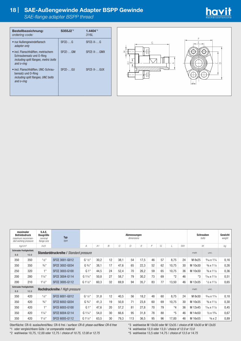
18 | SAE-Außengewinde Adapter BSPP Gewinde SAE-flange adapter BSPP thread
Bestellbezeichnung:ordering code:
S355J2 *1 1.4404 *1
316L
• nur Außengewindeflansch adaptor only
SFCE-…G SFCE-X-…G
• incl. Flanschhälften, metrischem Schraubensatz und O-Ring including split flanges, metric bolts and o-ring
SFCE-…GM SFCE-X-…GMX
• incl. Flanschhälften, UNC-Schrau-bensatz und O-Ring including split flanges, UNC bolts and o-ring
SFCE-…GU SFCE-X-…GUX
maximaler Betriebsdruck
maximum recommen-ded working pressure
S.A.E. Baugröße
nominal flange size
Typtype
Abmessungendimensions
Schraubenbolts
Gewichtweight
kg/cm² inch A A1 B C D E F G L SW M kg
Schraube Festigkeitskl.Standarddruckreihe / Standard pressure metr. unc.
8.8 10.9
350 350 ¹ ⁄₂" SFCE 3001-G012 G ¹ ⁄₂" 30,2 12 38,1 54 17,5 46 57 8,75 24 M 8x25 ⁵⁄₁₆ x 1¹⁄₄ 0,16
350 350 ³⁄₄" SFCE 3002-G034 G ³⁄₄" 38,1 17 47,6 65 22,3 52 62 10,75 30 M 10x30 ³⁄₈ x 1¹ ⁄₂ 0,26
250 320 1" SFCE 3003-G100 G 1" 44,5 24 52,4 70 26,2 59 65 10,75 36 M 10x30 ³⁄₈ x 1¹ ⁄₂ 0,36
200 280 1¹⁄₄" SFCE 3004-G114 G 1¹⁄₄" 50,8 27 58,7 79 30,2 73 69 *2 46 *3 ⁷⁄₁₆ x 1¹ ⁄₂ 0,51
200 210 1¹ ⁄₂" SFCE 3005-G112 G 1¹ ⁄₂" 60,3 32 69,9 94 35,7 83 77 13,50 46 M 12x35 ¹ ⁄₂ x 1¹ ⁄₂ 0,65Schraube Festigkeitskl.
Hochdruckreihe / High pressure metr. unc.8.8 10.9
350 420 ¹ ⁄₂" SFCE 6001-G012 G ¹ ⁄₂" 31,8 12 40,5 56 18,2 48 60 8,75 24 M 8x30 ⁵⁄₁₆ x 1¹⁄₄ 0,18
350 420 ³⁄₄" SFCE 6002-G034 G ³⁄₄" 41,3 19 50,8 71 23,8 60 69 10,75 30 M 10x35 ³⁄₈ x 1¹ ⁄₂ 0,30
350 420 1" SFCE 6003-G100 G 1" 47,6 20 57,2 81 27,8 70 79 *4 36 M 12x45 ⁷⁄₁₆ x 1¹ ⁄₂ 0,45
350 420 1¹⁄₄" SFCE 6004-G114 G 1¹⁄₄" 54,0 30 66,6 95 31,8 78 88 *5 46 M 14x50 ¹⁄₂ x 1³⁄₄ 0,67
350 420 1¹ ⁄₂" SFCE 6005-G112 G 1¹ ⁄₂" 63,5 30 79,3 113 36,5 95 96 17,00 46 M 16x55 ⁵⁄₈ x 2 0,89
Oberfläche: CR-6: auslaufend/Neu: CR-6 frei / surface: CR-6: phase-out/New: CR-6 free*1 oder vergleichbare Güte / or comparable material*2 wahlweise 10,75, 12,00 oder 12,75 / choice of 10.75, 12.00 or 12.75
*3 wahlweise M 10x30 oder M 12x35 / choice of M 10x30 or M 12x35*4 wahlweise 12,0 oder 13,0 / choice of 12.0 or 13.0 *5 wahlweise 13,5 oder 14,75 / choice of 13.5 or 14.75
Bestellbezeichnung:ordering code:
S355J2 *1
C221.4404 *1
316L
• nur Außengewindeflansch adaptor only
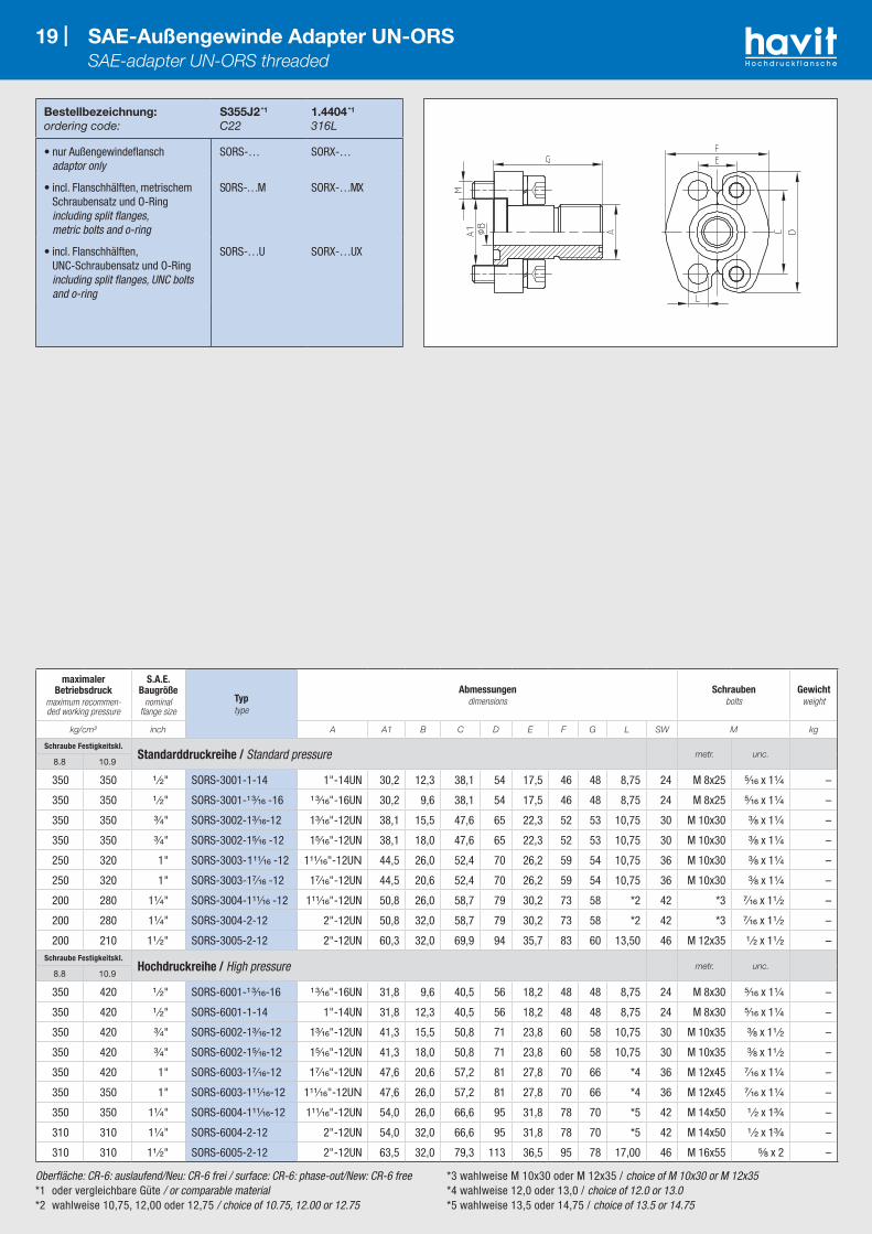
SORS-… SORX-…
• incl. Flanschhälften, metrischem Schraubensatz und O-Ring including split flanges, metric bolts and o-ring
SORS-…M SORX-…MX
• incl. Flanschhälften, UNC-Schraubensatz und O-Ring including split flanges, UNC bolts and o-ring
SORS-…U SORX-…UX
19 | SAE-Außengewinde Adapter UN-ORS SAE-adapter UN-ORS threaded
maximaler Betriebsdruck
maximum recommen-ded working pressure
S.A.E. Baugröße
nominal flange size
Typtype
Abmessungendimensions
Schraubenbolts
Gewichtweight
kg/cm² inch A A1 B C D E F G L SW M kg
Schraube Festigkeitskl.Standarddruckreihe / Standard pressure metr. unc.
8.8 10.9
350 350 ¹ ⁄₂" SORS-3001-1-14 1"-14UN 30,2 12,3 38,1 54 17,5 46 48 8,75 24 M 8x25 ⁵⁄₁₆ x 1¹⁄₄ –
350 350 ¹ ⁄₂" SORS-3001-¹ ³⁄₁₆ -16 ¹ ³⁄₁₆"-16UN 30,2 9,6 38,1 54 17,5 46 48 8,75 24 M 8x25 ⁵⁄₁₆ x 1¹⁄₄ –
350 350 ³⁄₄" SORS-3002-1³⁄₁₆-12 1³⁄₁₆"-12UN 38,1 15,5 47,6 65 22,3 52 53 10,75 30 M 10x30 ³⁄₈ x 1¹⁄₄ –
350 350 ³⁄₄" SORS-3002-1⁵⁄₁₆ -12 1⁵⁄₁₆"-12UN 38,1 18,0 47,6 65 22,3 52 53 10,75 30 M 10x30 ³⁄₈ x 1¹⁄₄ –
250 320 1" SORS-3003-1¹¹⁄₁₆ -12 1¹¹⁄₁₆"-12UN 44,5 26,0 52,4 70 26,2 59 54 10,75 36 M 10x30 ³⁄₈ x 1¹⁄₄ –
250 320 1" SORS-3003-1⁷⁄₁₆ -12 1⁷⁄₁₆"-12UN 44,5 20,6 52,4 70 26,2 59 54 10,75 36 M 10x30 ³⁄₈ x 1¹⁄₄ –
200 280 1¹⁄₄" SORS-3004-1¹¹⁄₁₆ -12 1¹¹⁄₁₆"-12UN 50,8 26,0 58,7 79 30,2 73 58 *2 42 *3 ⁷⁄₁₆ x 1¹ ⁄₂ –
200 280 1¹⁄₄" SORS-3004-2-12 2"-12UN 50,8 32,0 58,7 79 30,2 73 58 *2 42 *3 ⁷⁄₁₆ x 1¹ ⁄₂ –
200 210 1¹ ⁄₂" SORS-3005-2-12 2"-12UN 60,3 32,0 69,9 94 35,7 83 60 13,50 46 M 12x35 ¹ ⁄₂ x 1¹ ⁄₂ –Schraube Festigkeitskl.
Hochdruckreihe / High pressure metr. unc.8.8 10.9
350 420 ¹ ⁄₂" SORS-6001-¹ ³⁄₁₆-16 ¹ ³⁄₁₆"-16UN 31,8 9,6 40,5 56 18,2 48 48 8,75 24 M 8x30 ⁵⁄₁₆ x 1¹⁄₄ –
350 420 ¹ ⁄₂" SORS-6001-1-14 1"-14UN 31,8 12,3 40,5 56 18,2 48 48 8,75 24 M 8x30 ⁵⁄₁₆ x 1¹⁄₄ –
350 420 ³⁄₄" SORS-6002-1³⁄₁₆-12 1³⁄₁₆"-12UN 41,3 15,5 50,8 71 23,8 60 58 10,75 30 M 10x35 ³⁄₈ x 1¹ ⁄₂ –
350 420 ³⁄₄" SORS-6002-1⁵⁄₁₆-12 1⁵⁄₁₆"-12UN 41,3 18,0 50,8 71 23,8 60 58 10,75 30 M 10x35 ³⁄₈ x 1¹ ⁄₂ –
350 420 1" SORS-6003-1⁷⁄₁₆-12 1⁷⁄₁₆"-12UN 47,6 20,6 57,2 81 27,8 70 66 *4 36 M 12x45 ⁷⁄₁₆ x 1¹⁄₄ –
350 350 1" SORS-6003-1¹¹⁄₁₆-12 1¹¹⁄₁₆"-12UN 47,6 26,0 57,2 81 27,8 70 66 *4 36 M 12x45 ⁷⁄₁₆ x 1¹⁄₄ –
350 350 1¹⁄₄" SORS-6004-1¹¹⁄₁₆-12 1¹¹⁄₁₆"-12UN 54,0 26,0 66,6 95 31,8 78 70 *5 42 M 14x50 ¹ ⁄₂ x 1³⁄₄ –
310 310 1¹⁄₄" SORS-6004-2-12 2"-12UN 54,0 32,0 66,6 95 31,8 78 70 *5 42 M 14x50 ¹ ⁄₂ x 1³⁄₄ –
310 310 1¹ ⁄₂" SORS-6005-2-12 2"-12UN 63,5 32,0 79,3 113 36,5 95 78 17,00 46 M 16x55 ⁵⁄₈ x 2 –

*1 oder vergleichbare Güte / or comparable material*2 L=13,5 für UNC-Schrauben / L=13.5 with UNC-bolts
Bestellbezeichnung:ordering code:
S355J2 *1 1.4404 *1
316L
• nur Flansch flange only
AFS-…S AFX-…S
• incl. metrischem Schraubensatz und O-Ring including metric bolts and o-ring
AFS-…SM AFX-…SMX
• incl. UNC Schraubensatz und O-Ring including UNC bolts and o-ring
AFS-…SU AFX-…SUX
20 | SAE-Einschweißflansch SAE-socket weld flange
maximaler Betriebsdruck
maximum recommen-ded working pressure
S.A.E. Baugröße
nominal flange size
Typtype
Abmessungendimensions
Schraubenbolts
Gewichtweight
kg/cm² inch A B C D E F G H I L M kg
Schraube Festigkeitskl.Standarddruckreihe / Standard pressure metr. unc.
8.8 10.9
350 350 ¹ ⁄₂" AFS 080 S 21,6 13 38,1 54 17,5 46 36 16 19 9,0 M 8x30 ⁵⁄₁₆ x 1¹⁄₄ 0,25
350 350 ¹ ⁄₂" AFS 080 S-038 17,5 13 38,1 54 17,5 46 36 16 19 9,0 M 8x30 ⁵⁄₁₆ x 1¹⁄₄ 0,28
350 350 ¹ ⁄₂" AFS 080 S A20 20,3 13 38,1 54 17,5 46 36 16 19 9,0 M 8x30 ⁵⁄₁₆ x 1¹⁄₄ 0,25
350 350 ³⁄₄" AFS 100 S 27,2 19 47,6 65 22,3 50 36 18 19 11,0 M 10x35 ³⁄₈ x 1¹ ⁄₂ 0,39
350 350 ³⁄₄" AFS 100 S A25 25,3 19 47,6 65 22,3 50 36 18 19 11,0 M 10x35 ³⁄₈ x 1¹ ⁄₂ 0,39
250 320 1" AFS 102 S 34,0 25 52,4 70 26,2 55 38 18 19 11,0 M 10x35 ³⁄₈ x 1¹ ⁄₂ 0,46
250 320 1" AFS 102 S A30 30,3 25 52,4 70 26,2 55 38 18 19 11,0 M 10x35 ³⁄₈ x 1¹ ⁄₂ 0,46
200 280 1¹⁄₄" AFS 104 S 42,8 32 58,7 79 30,2 68 41 21 22 11,5 M 10x40 ⁷⁄₁₆ x 1¹ ⁄₂ 0,66
200 280 1¹⁄₄" AFS 104 S A38 38,3 32 58,7 79 30,2 68 41 21 22 11,5 M 10x40 ⁷⁄₁₆ x 1¹ ⁄₂ 0,66
200 210 1¹ ⁄₂" AFS 106 S 48,6 38 69,9 93 35,7 78 45 25 24 13,5 M 12x45 ¹ ⁄₂ x 1³⁄₄ 1,05
200 210 1¹ ⁄₂" AFS 106 S A50 50,5 38 69,9 93 35,7 78 45 25 24 13,5 M 12x45 ¹ ⁄₂ x 1³⁄₄ 1,05
160 210 2" AFS 108 S 61,0 51 77,8 102 42,9 90 45 25 26 13,5 M 12x45 ¹ ⁄₂ x 1³⁄₄ 1,19
100 175 2¹ ⁄₂" AFS 110 S 76,6 63 88,9 114 50,8 105 50 25 30 13,5 M 12x45 ¹ ⁄₂ x 1³⁄₄ 1,40
100 160 3" AFS 112 S 90,5 73 106,4 134 61,9 124 50 27 34 17,5 M 16x50 ⁵⁄₈ x 2 2,15
35 35 3¹ ⁄₂" AFS 114 S 103,0 89 120,7 152 69,9 136 48 27 34 17,5 M 16x50 ⁵⁄₈ x 2 2,40
35 35 4" AFS 116 S 115,5 99 130,2 162 77,8 146 48 27 34 17,5 M 16x50 ⁵⁄₈ x 2 2,85
35 35 5" AFS 118 S 142,0 120 152,4 184 92,1 181 50 28 28 17,5 M 16x55 ⁵⁄₈ x 2 5,80Schraube Festigkeitskl.
Hochdruckreihe / High pressure metr. unc.8.8 10.9
350 420 ¹ ⁄₂" AFS 401 S-012 21,6 13 40,5 54 18,2 46 36 16 19 9,0 M 8x30 ⁵⁄₁₆ x 1¹⁄₄ 0,26
350 420 ¹ ⁄₂" AFS 401 S-038 17,5 13 40,5 54 18,2 46 36 16 19 9,0 M 8x30 ⁵⁄₁₆ x 1¹⁄₄ 0,29
350 420 ¹ ⁄₂" AFS 401 S A20 20,3 13 40,5 54 18,2 46 36 16 19 9,0 M 8x30 ⁵⁄₁₆ x 1¹⁄₄ 0,26
350 420 ³⁄₄" AFS 402 S 27,2 19 50,8 71 23,8 55 35 21 22 11,0 M 10x35 ³⁄₈ x 1¹ ⁄₂ 0,50
350 420 ³⁄₄" AFS 402 S A25 25,3 19 50,8 71 23,8 55 35 21 22 11,0 M 10x35 ³⁄₈ x 1¹ ⁄₂ 0,50
350 420 1" AFS 403 S 34,0 25 57,2 81 27,8 65 42 25 22 13,0 M 12x45 ⁷⁄₁₆ x 1³⁄₄ 0,76
350 420 1" AFS 403 S A30 30,3 25 57,2 81 27,8 65 42 25 22 13,0 M 12x45 ⁷⁄₁₆ x 1³⁄₄ 0,76
350 420 1¹⁄₄" AFS 404 S 42,8 32 66,6 95 31,8 78 45 27 25 15,0 *2 M 14x50 ¹ ⁄₂ x 1³⁄₄ 1,20
350 420 1¹⁄₄" AFS 404 S A38 38,3 32 66,6 95 31,8 78 45 27 25 15,0 *2 M 14x50 ¹ ⁄₂ x 1³⁄₄ 1,20
350 420 1¹ ⁄₂" AFS 405 S 48,6 38 79,3 112 36,5 94 50 30 28 17,5 M 16x50 ⁵⁄₈ x 2 1,65
350 420 1¹ ⁄₂" AFS 405 S A50 50,5 38 79,3 112 36,5 94 50 30 28 17,5 M 16x50 ⁵⁄₈ x 2 1,65
350 420 2" AFS 406 S 61,0 51 96,8 134 44,5 114 65 37 24 21,0 M 20x70 ³⁄₄ x 2¹ ⁄₂ 2,45
350 420 2¹ ⁄₂" AFS 407 S 76,6 63 123,8 180 58,8 152 80 45 30 26,0 M 24x80 – 8,30
350 420 3" AFS 408 S 90,5 73 152,4 208 71,6 178 90 55 33 33,0 M 30x90 – 11,81

21 |
*1 oder vergleichbare Güte / or comparable material
Bestellbezeichnung:ordering code:
S355J2 *1
1.4404 *1
316L
• Flansch mit metrischen Gewinden flange with metric threads
GFS-…SM GFX-…SM
• Flansch mit UNC-Gewinden flange with UNC threads
GFS-…SU GFX-…SU
21 | SAE-Einschweiß-Gegenflansch SAE-socket weld flange companion
maximaler Betriebsdruck
maximum recommen-ded working pressure
S.A.E. Baugröße
nominal flange size
Typtype
Abmessungendimensions
Gewindethread
Gewichtweight
kg/cm² inch A B C D E F G H I M kg
Schraube Festigkeitskl.Standarddruckreihe / Standard pressure metr. unc.
8.8 10.9
350 350 ¹ ⁄₂" GFS 080 S 21,6 13 38,1 54 17,5 46 36 16 19 M 8 ⁵⁄₁₆ 0,25
350 350 ¹ ⁄₂" GFS 080 S-038 17,5 13 38,1 54 17,5 46 36 16 19 M 8 ⁵⁄₁₆ 0,28
350 350 ¹ ⁄₂" GFS 080 S-A20 20,3 13 38,1 54 17,5 46 36 16 19 M 8 ⁵⁄₁₆ 0,25
350 350 ³⁄₄" GFS 100 S 27,2 19 47,6 65 22,3 50 36 18 19 M 10 ³⁄₈ 0,39
350 350 ³⁄₄" GFS 100 S-A25 25,3 19 47,6 65 22,3 50 36 18 19 M 10 ³⁄₈ 0,39
250 320 1" GFS 102 S 34,0 25 52,4 70 26,2 55 38 18 19 M 10 ³⁄₈ 0,46
250 320 1" GFS 102 S-A30 30,3 25 52,4 70 26,2 55 38 18 19 M 10 ³⁄₈ 0,46
200 280 1¹⁄₄" GFS 104 S 42,8 32 58,7 79 30,2 68 41 21 22 M 10 ⁷⁄₁₆ 0,66
200 280 1¹⁄₄" GFS 104 S-A38 38,3 32 58,7 79 30,2 68 41 21 22 M 10 ⁷⁄₁₆ 0,66
200 210 1¹ ⁄₂" GFS 106 S 48,6 38 69,9 93 35,7 78 45 25 24 M 12 ¹ ⁄₂ 1,05
200 210 1¹ ⁄₂" GFS 106 S-A50 50,5 38 69,9 93 35,7 78 45 25 24 M 12 ¹ ⁄₂ 1,05
160 210 2" GFS 108 S 61,0 51 77,8 102 42,9 90 45 25 26 M 12 ¹ ⁄₂ 1,19
100 175 2¹ ⁄₂" GFS 110 S 76,6 63 88,9 114 50,8 105 50 25 30 M 12 ¹ ⁄₂ 1,40
100 160 3" GFS 112 S 90,5 73 106,4 134 61,9 124 50 27 34 M 16 ⁵⁄₈ 2,15
35 35 3¹ ⁄₂" GFS 114 S 103,0 89 120,7 152 69,9 136 48 27 34 M 16 ⁵⁄₈ 2,40
35 35 4" GFS 116 S 115,5 99 130,2 162 77,8 146 48 27 34 M 16 ⁵⁄₈ 2,85
35 35 5" GFS 118 S 142,0 120 152,4 184 92,1 181 50 28 28 M 16 ⁵⁄₈ 5,80Schraube Festigkeitskl.
Hochdruckreihe / High pressure metr. unc.8.8 10.9
350 420 ¹ ⁄₂" GFS 401 S-012 21,6 13 40,5 54 18,2 46 36 16 19 M 8 ⁵⁄₁₆ 0,26
350 420 ¹ ⁄₂" GFS 401 S-038 17,5 13 40,5 54 18,2 46 36 16 19 M 8 ⁵⁄₁₆ 0,29
350 420 ¹ ⁄₂" GFS 401 S-A20 20,3 13 40,5 54 18,2 46 36 16 19 M 8 ⁵⁄₁₆ 0,26
350 420 ³⁄₄" GFS 402 S 27,2 19 50,8 71 23,8 55 35 21 22 M 10 ³⁄₈ 0,50
350 420 ³⁄₄" GFS 402 S-A25 25,3 19 50,8 71 23,8 55 35 21 22 M 10 ³⁄₈ 0,50
350 420 1" GFS 403 S 34,0 25 57,2 81 27,8 65 42 25 22 M 12 ⁷⁄₁₆ 0,76
350 420 1" GFS 403 S-A30 30,3 25 57,2 81 27,8 65 42 25 22 M 12 ⁷⁄₁₆ 0,76
350 420 1¹⁄₄" GFS 404 S 42,8 32 66,6 95 31,8 78 45 27 25 M 14 ¹ ⁄₂ 1,20
350 420 1¹⁄₄" GFS 404 S-A38 38,3 32 66,6 95 31,8 78 45 27 25 M 14 ¹ ⁄₂ 1,20
350 420 1¹ ⁄₂" GFS 405 S 48,6 38 79,3 112 36,5 94 50 30 28 M 16 ⁵⁄₈ 1,65
350 420 1¹ ⁄₂" GFS 405 S-A50 50,5 38 79,3 112 36,5 94 50 30 28 M 16 ⁵⁄₈ 1,65
350 420 2" GFS 406 S 61,0 51 96,8 134 44,5 114 65 37 24 M 20 ³⁄₄ 2,45
350 420 2¹ ⁄₂" GFS 407 S 76,6 63 123,8 180 58,8 152 80 45 30 M 24 – 8,30
350 420 3" GFS 408 S 90,5 73 152,4 208 71,6 178 90 55 33 M 30 – 12,29
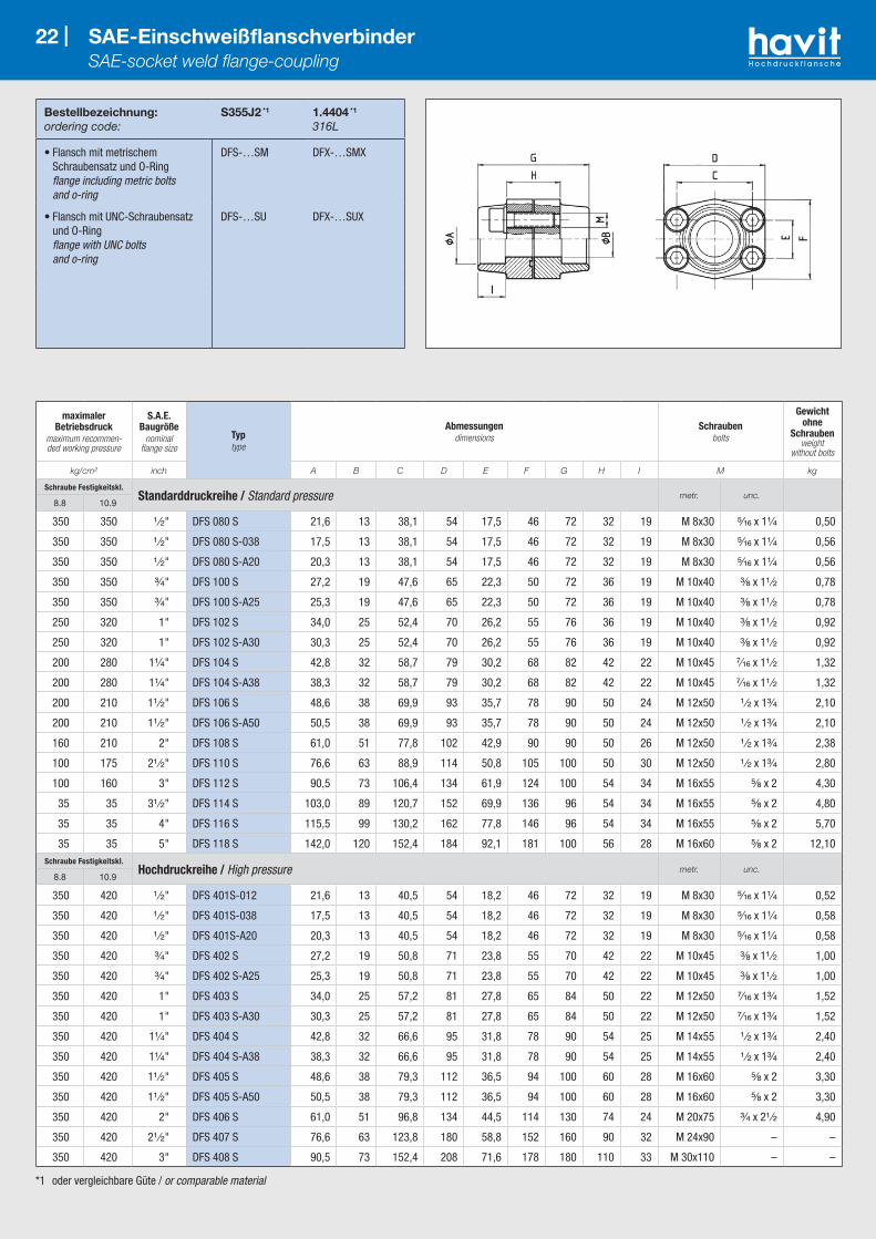
*1 oder vergleichbare Güte / or comparable material
Bestellbezeichnung:ordering code:
S355J2 *1
1.4404 *1
316L
• Flansch mit metrischem Schraubensatz und O-Ring flange including metric bolts and o-ring
DFS-…SM DFX-…SMX
• Flansch mit UNC-Schraubensatz und O-Ring flange with UNC bolts and o-ring
DFS-…SU DFX-…SUX
22 | SAE-Einschweißflanschverbinder SAE-socket weld flange-coupling
maximaler Betriebsdruck
maximum recommen-ded working pressure
S.A.E. Baugröße
nominal flange size
Typtype
Abmessungendimensions
Schraubenbolts
Gewicht ohne
Schrauben weight
without bolts
kg/cm² inch A B C D E F G H I M kg
Schraube Festigkeitskl.Standarddruckreihe / Standard pressure metr. unc.
8.8 10.9
350 350 ¹ ⁄₂" DFS 080 S 21,6 13 38,1 54 17,5 46 72 32 19 M 8x30 ⁵⁄₁₆ x 1¹⁄₄ 0,50
350 350 ¹ ⁄₂" DFS 080 S-038 17,5 13 38,1 54 17,5 46 72 32 19 M 8x30 ⁵⁄₁₆ x 1¹⁄₄ 0,56
350 350 ¹ ⁄₂" DFS 080 S-A20 20,3 13 38,1 54 17,5 46 72 32 19 M 8x30 ⁵⁄₁₆ x 1¹⁄₄ 0,56
350 350 ³⁄₄" DFS 100 S 27,2 19 47,6 65 22,3 50 72 36 19 M 10x40 ³⁄₈ x 1¹ ⁄₂ 0,78
350 350 ³⁄₄" DFS 100 S-A25 25,3 19 47,6 65 22,3 50 72 36 19 M 10x40 ³⁄₈ x 1¹ ⁄₂ 0,78
250 320 1" DFS 102 S 34,0 25 52,4 70 26,2 55 76 36 19 M 10x40 ³⁄₈ x 1¹ ⁄₂ 0,92
250 320 1" DFS 102 S-A30 30,3 25 52,4 70 26,2 55 76 36 19 M 10x40 ³⁄₈ x 1¹ ⁄₂ 0,92
200 280 1¹⁄₄" DFS 104 S 42,8 32 58,7 79 30,2 68 82 42 22 M 10x45 ⁷⁄₁₆ x 1¹ ⁄₂ 1,32
200 280 1¹⁄₄" DFS 104 S-A38 38,3 32 58,7 79 30,2 68 82 42 22 M 10x45 ⁷⁄₁₆ x 1¹ ⁄₂ 1,32
200 210 1¹ ⁄₂" DFS 106 S 48,6 38 69,9 93 35,7 78 90 50 24 M 12x50 ¹ ⁄₂ x 1³⁄₄ 2,10
200 210 1¹ ⁄₂" DFS 106 S-A50 50,5 38 69,9 93 35,7 78 90 50 24 M 12x50 ¹ ⁄₂ x 1³⁄₄ 2,10
160 210 2" DFS 108 S 61,0 51 77,8 102 42,9 90 90 50 26 M 12x50 ¹ ⁄₂ x 1³⁄₄ 2,38
100 175 2¹ ⁄₂" DFS 110 S 76,6 63 88,9 114 50,8 105 100 50 30 M 12x50 ¹ ⁄₂ x 1³⁄₄ 2,80
100 160 3" DFS 112 S 90,5 73 106,4 134 61,9 124 100 54 34 M 16x55 ⁵⁄₈ x 2 4,30
35 35 3¹ ⁄₂" DFS 114 S 103,0 89 120,7 152 69,9 136 96 54 34 M 16x55 ⁵⁄₈ x 2 4,80
35 35 4" DFS 116 S 115,5 99 130,2 162 77,8 146 96 54 34 M 16x55 ⁵⁄₈ x 2 5,70
35 35 5" DFS 118 S 142,0 120 152,4 184 92,1 181 100 56 28 M 16x60 ⁵⁄₈ x 2 12,10Schraube Festigkeitskl.
Hochdruckreihe / High pressure metr. unc.8.8 10.9
350 420 ¹ ⁄₂" DFS 401S-012 21,6 13 40,5 54 18,2 46 72 32 19 M 8x30 ⁵⁄₁₆ x 1¹⁄₄ 0,52
350 420 ¹ ⁄₂" DFS 401S-038 17,5 13 40,5 54 18,2 46 72 32 19 M 8x30 ⁵⁄₁₆ x 1¹⁄₄ 0,58
350 420 ¹ ⁄₂" DFS 401S-A20 20,3 13 40,5 54 18,2 46 72 32 19 M 8x30 ⁵⁄₁₆ x 1¹⁄₄ 0,58
350 420 ³⁄₄" DFS 402 S 27,2 19 50,8 71 23,8 55 70 42 22 M 10x45 ³⁄₈ x 1¹ ⁄₂ 1,00
350 420 ³⁄₄" DFS 402 S-A25 25,3 19 50,8 71 23,8 55 70 42 22 M 10x45 ³⁄₈ x 1¹ ⁄₂ 1,00
350 420 1" DFS 403 S 34,0 25 57,2 81 27,8 65 84 50 22 M 12x50 ⁷⁄₁₆ x 1³⁄₄ 1,52
350 420 1" DFS 403 S-A30 30,3 25 57,2 81 27,8 65 84 50 22 M 12x50 ⁷⁄₁₆ x 1³⁄₄ 1,52
350 420 1¹⁄₄" DFS 404 S 42,8 32 66,6 95 31,8 78 90 54 25 M 14x55 ¹ ⁄₂ x 1³⁄₄ 2,40
350 420 1¹⁄₄" DFS 404 S-A38 38,3 32 66,6 95 31,8 78 90 54 25 M 14x55 ¹ ⁄₂ x 1³⁄₄ 2,40
350 420 1¹ ⁄₂" DFS 405 S 48,6 38 79,3 112 36,5 94 100 60 28 M 16x60 ⁵⁄₈ x 2 3,30
350 420 1¹ ⁄₂" DFS 405 S-A50 50,5 38 79,3 112 36,5 94 100 60 28 M 16x60 ⁵⁄₈ x 2 3,30
350 420 2" DFS 406 S 61,0 51 96,8 134 44,5 114 130 74 24 M 20x75 ³⁄₄ x 2¹ ⁄₂ 4,90
350 420 2¹ ⁄₂" DFS 407 S 76,6 63 123,8 180 58,8 152 160 90 32 M 24x90 – –
350 420 3" DFS 408 S 90,5 73 152,4 208 71,6 178 180 110 33 M 30x110 – –
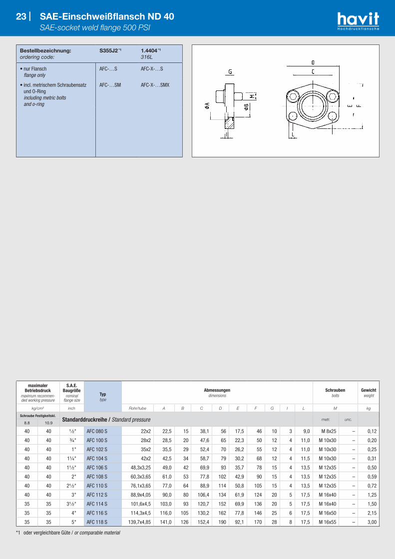
*1 oder vergleichbare Güte / or comparable material
Bestellbezeichnung:ordering code:
S355J2 *1
1.4404 *1
316L
• nur Flansch flange only
AFC-…S AFC-X-…S
• incl. metrischem Schraubensatz und O-Ring including metric bolts and o-ring
AFC-…SM AFC-X-…SMX
23 | SAE-Einschweißflansch ND 40 SAE-socket weld flange 500 PSI
maximaler Betriebsdruck
maximum recommen-ded working pressure
S.A.E. Baugröße
nominal flange size
Typtype
Abmessungendimensions
Schraubenbolts
Gewichtweight
kg/cm² inch Rohr/tube A B C D E F G I L M kg
Schraube Festigkeitskl.Standarddruckreihe / Standard pressure metr. unc.
8.8 10.9
40 40 ¹ ⁄₂" AFC 080 S 22x2 22,5 15 38,1 56 17,5 46 10 3 9,0 M 8x25 – 0,12
40 40 ³⁄₄" AFC 100 S 28x2 28,5 20 47,6 65 22,3 50 12 4 11,0 M 10x30 – 0,20
40 40 1" AFC 102 S 35x2 35,5 29 52,4 70 26,2 55 12 4 11,0 M 10x30 – 0,25
40 40 1¹⁄₄" AFC 104 S 42x2 42,5 34 58,7 79 30,2 68 12 4 11,5 M 10x30 – 0,31
40 40 1¹ ⁄₂" AFC 106 S 48,3x3,25 49,0 42 69,9 93 35,7 78 15 4 13,5 M 12x35 – 0,50
40 40 2" AFC 108 S 60,3x3,65 61,0 53 77,8 102 42,9 90 15 4 13,5 M 12x35 – 0,59
40 40 2¹ ⁄₂" AFC 110 S 76,1x3,65 77,0 64 88,9 114 50,8 105 15 4 13,5 M 12x35 – 0,72
40 40 3" AFC 112 S 88,9x4,05 90,0 80 106,4 134 61,9 124 20 5 17,5 M 16x40 – 1,25
35 35 3¹ ⁄₂" AFC 114 S 101,6x4,5 103,0 93 120,7 152 69,9 136 20 5 17,5 M 16x40 – 1,50
35 35 4" AFC 116 S 114,3x4,5 116,0 105 130,2 162 77,8 146 25 6 17,5 M 16x50 – 2,15
35 35 5" AFC 118 S 139,7x4,85 141,0 126 152,4 190 92,1 170 28 8 17,5 M 16x55 – 3,00

*1 oder vergleichbare Güte / or comparable material
Bestellbezeichnung:ordering code:
S355J2 *1
1.4404 *1
316L
• nur Flansch flange only
GFC-…S GFC-X-…S
24 | SAE-Einschweiß-Gegenflansch ND 40 SAE-socket weld companion 500 PSI
maximaler Betriebsdruck
maximum recommen-ded working pressure
S.A.E. Baugröße
nominal flange size
Typtype
Abmessungendimensions
Gewindethread
Gewichtweight
kg/cm² inch Rohr/tube A B C D E F G I M kg
Schraube Festigkeitskl.Standarddruckreihe / Standard pressure
8.8 10.9
40 40 ¹ ⁄₂" GFC 080 S 22x2 22,5 15 38,1 56 17,5 46 10 3 M 8 0,12
40 40 ³⁄₄" GFC 100 S 28x2 28,5 20 47,6 65 22,3 50 12 4 M 10 0,20
40 40 1" GFC 102 S 35x2 35,5 29 52,4 70 26,2 55 12 4 M 10 0,25
40 40 1¹⁄₄" GFC 104 S 42x2 42,5 34 58,7 79 30,2 68 12 4 M 10 0,31
40 40 1¹ ⁄₂" GFC 106 S 48,3x3,25 49,0 42 69,9 93 35,7 78 15 4 M 12 0,50
40 40 2" GFC 108 S 60,3x3,65 61,0 53 77,8 102 42,9 90 15 4 M 12 0,59
40 40 2¹ ⁄₂" GFC 110 S 76,1x3,65 77,0 64 88,9 114 50,8 105 15 4 M 12 0,72
40 40 3" GFC 112 S 88,9x4,05 90,0 80 106,4 134 61,9 124 20 5 M 16 1,25
35 35 3¹ ⁄₂" GFC 114 S 101,6x4,5 103,0 93 120,7 152 69,9 136 20 5 M 16 1,50
35 35 4" GFC 116 S 114,3x4,5 116,0 105 130,2 162 77,8 146 25 6 M 16 2,15
35 35 5" GFC 118 S 139,7x4,85 141,0 126 152,4 190 92,1 170 28 8 M 16 3,00

*1 oder vergleichbare Güte / or comparable material
Bestellbezeichnung:ordering code:
S355J2 *1
1.4404 *1
316L
• Flansch incl. Schraubensatz und O-Ring flange including bolts and o-ring
DFC-…SM DFC-X… SMX
25 | SAE-Einschweißflanschverbinder ND 40 SAE-socket weld flange-coupling 500 PSI
maximaler Betriebsdruck
maximum recommen-ded working pressure
S.A.E. Baugröße
nominal flange size
Typtype
Abmessungendimensions
Schraubenbolts
Gewichtweight
kg/cm² inch Rohr/tube A B C D E F G I M kg
Schraube Festigkeitskl.Standarddruckreihe / Standard pressure
8.8 10.9
40 40 ¹ ⁄₂" DFC 080 S 22x2 22,5 15 38,1 56 17,5 46 20 3 M 8x25 0,24
40 40 ³⁄₄" DFC 100 S 28x2 28,5 20 47,6 65 22,3 50 24 4 M 10x30 0,40
40 40 1" DFC 102 S 35x2 35,5 29 52,4 70 26,2 55 24 4 M 10x30 0,50
40 40 1¹⁄₄" DFC 104 S 42x2 42,5 34 58,7 79 30,2 68 24 4 M 10x30 0,62
40 40 1¹ ⁄₂" DFC 106 S 48,3x3,25 49,0 42 69,9 93 35,7 78 30 4 M 12x35 1,00
40 40 2" DFC 108 S 60,3x3,65 61,0 53 77,8 102 42,9 90 30 4 M 12x35 1,18
40 40 2¹ ⁄₂" DFC 110 S 76,1x3,65 77,0 64 88,9 114 50,8 105 30 4 M 12x35 1,44
40 40 3" DFC 112 S 88,9x4,05 90,0 80 106,4 134 61,9 124 40 5 M 16x40 2,50
35 35 3¹ ⁄₂" DFC 114 S 101,6x4,5 103,0 93 120,7 152 69,9 136 40 5 M 16x40 3,00
35 35 4" DFC 116 S 114,3x4,5 116,0 105 130,2 162 77,8 146 50 6 M 16x50 4,30
35 35 5" DFC 118 S 139,7x4,85 141,0 126 152,4 190 92,1 170 56 8 M 16x60 6,00

*1 oder vergleichbare Güte / or comparable material
Bestellbezeichnung:ordering code:
S355J2 *1
1.4404 *1
316L
• nur Flansch flange only
AFS-…ST AFX-…ST
• incl. metrischem Schraubensatz und O-Ring including metric bolts and o-ring
AFS-…STM AFX-…STMX
• incl. UNC-Schraubensatz und O-Ring including UNC bolts and o-ring
AFS-…STU AFX-…STUX
26 | SAE-Anschweißflansch – zöllig SAE-weld-on flange – inches
maximaler Betriebsdruck *
maximum recommen-ded working pressure
S.A.E. Baugröße
nominal flange size
Typtype
Abmessungendimensions
Schraubenbolts
Gewichtweight
kg/cm² inch A B C D E F G H L M kg
Schraube Festigkeitskl.Standarddruckreihe / Standard pressure metr. unc.
8.8 10.9
350 350 ¹ ⁄₂" AFS 080 ST 21,5 13,0 38,1 54 17,5 46 36 16 9,0 M 8x30 ⁵⁄₁₆ x 1¹⁄₄ 0,28
350 350 ¹ ⁄₂" AFS 080 ST-038 17,5 13,0 38,1 54 17,5 46 36 16 9,0 M 8x30 ⁵⁄₁₆ x 1¹⁄₄ 0,25
350 350 ³⁄₄" AFS 100 ST 28,0 19,0 47,6 65 22,3 50 36 18 11,0 M 10x35 ³⁄₈ x 1¹ ⁄₂ 0,39
250 320 1" AFS 102 ST 34,0 25,0 52,4 70 26,2 55 38 18 11,0 M 10x35 ³⁄₈ x 1¹ ⁄₂ 0,46
200 280 1¹⁄₄" AFS 104 ST 42,8 32,0 58,7 79 30,2 68 41 21 11,5 M 10x40 ⁷⁄₁₆ x 1¹ ⁄₂ 0,66
200 210 1¹ ⁄₂" AFS 106 ST 48,6 38,0 69,9 93 35,7 78 44 25 13,5 M 12x45 ¹ ⁄₂ x 1³⁄₄ 1,05
160 210 2" AFS 108 ST 61,0 51,0 77,8 102 42,9 90 45 25 13,5 M 12x45 ¹ ⁄₂ x 1³⁄₄ 1,19
100 175 2¹ ⁄₂" AFS 110 ST 77,0 63,0 88,9 114 50,8 105 50 25 13,5 M 12x45 ¹ ⁄₂ x 1³⁄₄ 1,40
100 160 3" AFS 112 ST 92,0 73,0 106,4 134 61,9 124 50 27 17,5 M 16x50 ⁵⁄₈ x 2 2,15
35 35 3¹ ⁄₂" AFS 114 ST 103,0 89,0 120,7 152 69,9 136 48 27 17,5 M 16x50 ⁵⁄₈ x 2 2,40
35 35 4" AFS 116 ST 115,5 99,0 130,2 162 77,8 146 48 27 17,5 M 16x50 ⁵⁄₈ x 2 2,85
35 35 5" AFS 118 ST 142,0 120,0 152,4 184 92,1 180 50 28 17,5 M 16x55 ⁵⁄₈ x 2 5,20Schraube Festigkeitskl.
Hochdruckreihe / High pressure metr. unc.8.8 10.9
350 420 ¹ ⁄₂" AFS 401 ST-012 21,5 13,0 40,5 54 18,2 46 36 16 9,0 M 8x30 ⁵⁄₁₆ x 1¹⁄₄ 0,29
350 420 ¹ ⁄₂" AFS 401 ST-038 17,5 13,0 40,5 54 18,2 46 36 16 9,0 M 8x30 ⁵⁄₁₆ x 1¹⁄₄ 0,26
350 420 ³⁄₄" AFS 402 ST 28,0 19,0 50,8 71 23,8 55 35 21 11,0 M 10x35 ³⁄₈ x 1¹ ⁄₂ 0,50
350 420 1" AFS 403 ST 34,0 25,0 57,2 79 27,8 68 41 21 13,0 M 12x45 ⁷⁄₁₆ x 1³⁄₄ 0,76
350 375 1¹⁄₄" AFS 404 ST 42,8 32,0 66,6 93 31,8 78 44 25 15,0 M 14x50 ¹ ⁄₂ x 1³⁄₄ 1,20
250 250 1¹ ⁄₂" AFS 405 ST 48,6 38,0 79,3 112 36,5 94 55 30 17,0 M 16x50 ⁵⁄₈ x 2 1,65
250 250 2" AFS 406 ST 61,0 51,0 96,8 134 44,5 114 65 37 21,0 M 20x70 ³⁄₄ x 2¹ ⁄₂ 2,45
350 420 2¹ ⁄₂" AFS 407 ST 76 76,1 51,0 123,8 180 58,8 152 80 45 26,0 M 24x80 – 6,40
350 420 2¹ ⁄₂" AFS 407 ST 88 90,0 60,5 123,8 180 58,8 152 80 45 26,0 M 24x80 – 8,30
* Der angeführte maximale Betriebsdruck ist bezogen auf den Flansch! Der tatsächliche Betriebsdruck wird bestimmt durch das Rohr (Wandstärke) sowie die Güte des Rohres! The maximum recommended working pressure is based on the flange. The working pressure of the system is determined by the tube (thickness) and by the steel quality of the tube!

*1 oder vergleichbare Güte / or comparable material
Bestellbezeichnung:ordering code:
S355J2 *1
1.4404 *1
316L
• Flansch mit metrischen Gewinden flange with metric threads
GFS-…STM GFX-…STM
• Flansch mit UNC-Gewinden flange with UNC threads
GFS-…STU GFX-…STU
27 | SAE-Anschweiß-Gegenflansch – zöllig SAE-weld-on flange companion – inches
maximaler Betriebsdruck *
maximum recommen-ded working pressure
S.A.E. Baugröße
nominal flange size
Typtype
Abmessungendimensions
Gewindethread
Gewichtweight
kg/cm² inch A B C D E F G H M kg
Schraube Festigkeitskl.Standarddruckreihe / Standard pressure metr. unc.
8.8 10.9
350 350 ¹ ⁄₂" GFS 080 ST 21,5 13,0 38,1 54 17,5 46 36 16 M 8 ⁵⁄₁₆ 0,25
350 350 ¹ ⁄₂" GFS 080 ST-038 17,5 13,0 38,1 54 17,5 46 36 16 M 8 ⁵⁄₁₆ 0,28
350 350 ³⁄₄" GFS 100 ST 28,0 19,0 47,6 65 22,3 50 36 18 M 10 ³⁄₈ 0,39
250 320 1" GFS 102 ST 34,0 25,0 52,4 70 26,2 55 38 18 M 10 ³⁄₈ 0,46
200 280 1¹⁄₄" GFS 104 ST 42,8 32,0 58,7 79 30,2 68 41 21 M 10 ⁷⁄₁₆ 0,66
200 210 1¹ ⁄₂" GFS 106 ST 48,6 38,0 69,9 93 35,7 78 44 25 M 12 ¹ ⁄₂ 1,05
160 210 2" GFS 108 ST 61,0 51,0 77,8 102 42,9 90 45 25 M 12 ¹ ⁄₂ 1,19
100 175 2¹ ⁄₂" GFS 110 ST 77,0 63,0 88,9 114 50,8 105 50 25 M 12 ¹ ⁄₂ 1,40
100 160 3" GFS 112 ST 92,0 73,0 106,4 134 61,9 124 50 27 M 16 ⁵⁄₈ 2,15
35 35 3¹ ⁄₂" GFS 114 ST 103,0 89,0 120,7 152 69,9 136 48 27 M 16 ⁵⁄₈ 2,40
35 35 4" GFS 116 ST 115,5 99,0 130,2 162 77,8 146 48 27 M 16 ⁵⁄₈ 2,85
35 35 5" GFS 118 ST 142,0 120,0 152,4 184 92,1 180 50 28 M 16 ⁵⁄₈ 5,20Schraube Festigkeitskl.
Hochdruckreihe / High pressure metr. unc.8.8 10.9
350 420 ¹ ⁄₂" GFS 401 ST-012 21,5 13,0 40,5 54 18,2 46 36 16 M 8 ⁵⁄₁₆ 0,26
350 420 ¹ ⁄₂" GFS 401 ST-038 17,5 13,0 40,5 54 18,2 46 36 16 M 8 ⁵⁄₁₆ 0,29
350 420 ³⁄₄" GFS 402 ST 28,0 19,0 50,8 71 23,8 55 35 21 M 10 ³⁄₈ 0,50
350 420 1" GFS 403 ST 34,0 25,0 57,2 79 27,8 68 41 21 M 12 ⁷⁄₁₆ 0,76
350 375 1¹⁄₄" GFS 404 ST 42,8 32,0 66,6 93 31,8 78 44 25 M 14 ¹ ⁄₂ 1,20
250 250 1¹ ⁄₂" GFS 405 ST 48,6 38,0 79,3 112 36,5 94 55 30 M 16 ⁵⁄₈ 1,65
250 250 2" GFS 406 ST 61,0 51,0 96,8 134 44,5 114 65 37 M 20 ³⁄₄ 2,45
350 420 2¹ ⁄₂" GFS 407 ST 76 76,1 51,0 123,8 180 58,8 152 80 45 M 24 – 6,40
350 420 2¹ ⁄₂" GFS 407 ST 88 90,0 60,5 123,8 180 58,8 152 80 45 M 24 – 8,30
* Der angeführte maximale Betriebsdruck ist bezogen auf den Flansch! Der tatsächliche Betriebsdruck wird bestimmt durch das Rohr (Wandstärke) sowie die Güte des Rohres! The maximum recommended working pressure is based on the flange. The working pressure of the system is determined by the tube (thickness) and by the steel quality of the tube!

*1 oder vergleichbare Güte / or comparable material
Bestellbezeichnung:ordering code:
S355J2 *1
1.4404 *1
316L
• nur Flansch flange only
AFS-…ST10 AFX-…ST10
• incl. metrischem Schraubensatz und O-Ring including metric bolts and o-ring
AFS-…ST10M AFX-…ST10MX
• incl. UNC-Schraubensatz und O-Ring including unc bolts and o-ring
AFS-…ST10U AFX-…ST10UX
28 | SAE-Anschweißflansch – Schedule 10 SAE-weld-on flange Schedule 10
maximaler Betriebsdruck *
maximum recommen-ded working pressure
S.A.E. Baugröße
nominal flange size
Typtype
Abmessungendimensions
Schraubenbolts
Gewichtweight
kg/cm² inch Rohr/tube A B1 B2 C D E F G H L M kg
Schraube Festigkeitskl.Standarddruckreihe / Standard pressure metr. unc.
8.8 10.9
250 320 1" AFS-102ST10 33,4x2,8 34,0 27,8 25,0 52,4 70 26,2 55 38 18 11,0 M10x35 ³⁄₈ x 1¹ ⁄₂ 0,40
200 280 1¹⁄₄" AFS-104ST10 42,2x2,8 42,8 36,6 32,0 58,7 79 30,2 68 41 21 11,5 M10x40 ⁷⁄₁₆ x 1¹ ⁄₂ 0,61
200 210 1¹ ⁄₂" AFS-106ST10 48,3x2,8 48,6 42,7 38,0 69,9 93 35,7 78 44 25 13,5 M12x45 ¹ ⁄₂ x 1³⁄₄ 0,96
160 210 2" AFS-108ST10 60,3x2,9 61,0 54,5 51,0 77,8 102 42,9 90 45 25 13,5 M12x45 ¹ ⁄₂ x 1³⁄₄ 1,11
100 175 2¹ ⁄₂" AFS-110ST10 73x3 73,0 67,0 63,0 88,9 114 50,8 105 50 25 13,5 M12x45 ¹ ⁄₂ x 1³⁄₄ 1,51
100 160 3" AFS-112ST10 88,9x3 92,0 82,9 73,0 106,4 134 61,9 124 50 27 17,5 M16x50 ⁵⁄₈ x 2 2,19
35 35 4" AFS-116ST10 114,3x3 115,5 108,3 99,0 130,2 162 77,8 146 48 27 17,5 M16x50 ⁵⁄₈ x 2 2,77
35 35 5" AFS-118ST10 141,3x3,4 142,0 134,5 120,0 152,4 184 92,1 180 50 28 17,5 M16x55 ⁵⁄₈ x 2 3,85
* Der angeführte maximale Betriebsdruck ist bezogen auf den Flansch! Der tatsächliche Betriebsdruck wird bestimmt durch das Rohr (Wandstärke) sowie die Güte des Rohres! The maximum recommended working pressure is based on the flange. The working pressure of the system is determined by the tube (thickness) and by the steel quality of the tube!

*1 oder vergleichbare Güte / or comparable material
Bestellbezeichnung:ordering code:
S355J2 *1
1.4404 *1
316L
• Flansch mit metrischen Gewinden flange with metric threads
GFS-…ST10 GFX-…ST10
• Flansch mit UNC-Gewinden flange with unc threads
GFS-…ST10U GFX-…ST10U
29 | SAE-Anschweiß-Gegenflansch – Schedule 10 SAE-weld-on flange companion – schedule 10
maximaler Betriebsdruck *
maximum recommen-ded working pressure
S.A.E. Baugröße
nominal flange size
Typtype
Abmessungendimensions
Gewindethread
Gewichtweight
kg/cm² inch Rohr/tube A B1 B2 C D E F G H M kg
Schraube Festigkeitskl.Standarddruckreihe / Standard pressure metr. unc.
8.8 10.9
250 320 1" GFS-102ST10 33,4x2,8 34,0 27,8 25,0 52,4 70 26,2 55 38 18 M10 ³⁄₈-16 –
200 280 1¹⁄₄" GFS-104ST10 42,2x2,8 42,8 36,6 32,0 58,7 79 30,2 68 41 21 M10 ⁷⁄₁₆-14 –
200 210 1¹ ⁄₂" GFS-106ST10 48,3x2,8 48,6 42,7 38,0 69,9 93 35,7 78 44 25 M12 ¹ ⁄₂-13 –
160 210 2" GFS-108ST10 60,3x2,9 61,0 54,5 51,0 77,8 102 42,9 90 45 25 M12 ¹ ⁄₂-13 –
100 175 2¹ ⁄₂" GFS-110ST10 73x3 73,0 67,0 63,0 88,9 114 50,8 105 50 25 M12 ¹ ⁄₂-13 –
100 160 3" GFS-112ST10 88,9x3 92,0 82,9 73,0 106,4 134 61,9 124 50 27 M16 ⁵⁄₈-11 –
35 35 4" GFS-116ST10 114,3x3 115,5 108,3 99,0 130,2 162 77,8 146 48 27 M16 ⁵⁄₈-11 –
35 35 5" GFS-118ST10 141,3x3,4 142,0 134,5 120,0 152,4 184 92,1 180 50 28 M16 ⁵⁄₈-11 –
* Der angeführte maximale Betriebsdruck ist bezogen auf den Flansch! Der tatsächliche Betriebsdruck wird bestimmt durch das Rohr (Wandstärke) sowie die Güte des Rohres! The maximum recommended working pressure is based on the flange. The working pressure of the system is determined by the tube (thickness) and by the steel quality of the tube!

*1 oder vergleichbare Güte / or comparable material
Bestellbezeichnung:ordering code:
S355J2 *1
1.4404 *1
316L
• nur Flansch flange only
AFS-…ST40 AFX-…ST40
• incl. metrischem Schraubensatz und O-Ring including metric bolts and o-ring
AFS-…ST40M AFX-…ST40MX
• incl. UNC-Schraubensatz und O-Ring including unc bolts and o-ring
AFS-…ST40U AFX-…ST40UX
30 | SAE-Anschweißflansch – Schedule 40 SAE-weld-on flange – schedule 40
maximaler Betriebsdruck *
maximum recommen-ded working pressure
S.A.E. Baugröße
nominal flange size
Typtype
Abmessungendimensions
Schraubenbolts
Gewichtweight
kg/cm² inch Rohr/tube A B1 B2 C D E F G H L M kg
Schraube Festigkeitskl.Standarddruckreihe / Standard pressure metr. unc.
8.8 10.9
350 350 ¹ ⁄₂" AFS-080ST40 21,3x2,8 21,5 15,7 13,0 38,1 54 17,5 46 36 16 9,0 M8x30 ⁵⁄₁₆ x 1¹⁄₄ 0,24
350 350 ³⁄₄" AFS-100ST40 26,7x2,9 28,0 20,9 19,0 47,6 65 22,3 50 36 18 11,0 M10x35 ³⁄₈ x 1¹ ⁄₂ 0,35
250 320 1" AFS-102ST40 33,4x3,4 34,0 26,6 25,0 52,4 70 26,2 55 38 18 11,0 M10x35 ³⁄₈ x 1¹ ⁄₂ 0,41
200 280 1¹⁄₄" AFS-104ST40 42,4x3,6 42,8 35,0 32,0 58,7 79 30,2 68 41 21 11,5 M10x40 ⁷⁄₁₆ x 1¹ ⁄₂ 0,62
200 210 1¹ ⁄₂" AFS-106ST40 48,3x3,7 48,6 40,9 38,0 69,9 93 35,7 78 44 25 13,5 M12x45 ¹ ⁄₂ x 1³⁄₄ 0,97
160 210 2" AFS-108ST40 60,3x3,9 61,0 52,5 51,0 77,8 102 42,9 90 45 25 13,5 M12x45 ¹ ⁄₂ x 1³⁄₄ 1,13
100 175 2¹ ⁄₂" AFS-110ST40 73x5,1 73,0 62,8 – 88,9 114 50,8 105 50 25 13,5 M12x45 ¹ ⁄₂ x 1³⁄₄ 1,54
100 160 3" AFS-112ST40 88,9x5,5 92,0 77,9 73,0 106,4 134 61,9 124 50 27 17,5 M16x50 ⁵⁄₈ x 2 2,25
35 35 3¹ ⁄₂" AFS-114ST40 101,6x5,7 103,0 90,1 89 120,7 152 69,9 136 48 27 17,5 M16x50 ⁵⁄₈ x 2 2,57
35 35 4" AFS-116ST40 114,3x6 115,5 102,3 99,0 130,2 162 77,8 146 48 27 17,5 M16x50 ⁵⁄₈ x 2 2,87
35 35 5" AFS-118ST40 141,3x6,6 142,0 128,1 120,0 152,4 184 92,1 180 50 28 17,5 M16x55 ⁵⁄₈ x 2 4,03
* Der angeführte maximale Betriebsdruck ist bezogen auf den Flansch! Der tatsächliche Betriebsdruck wird bestimmt durch das Rohr (Wandstärke) sowie die Güte des Rohres! The maximum recommended working pressure is based on the flange. The working pressure of the system is determined by the tube (thickness) and by the steel quality of the tube!
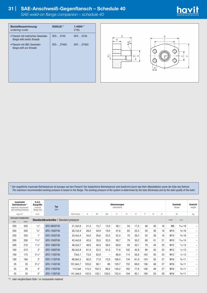
*1 oder vergleichbare Güte / or comparable material
Bestellbezeichnung:ordering code:
S355J2 *1
1.4404 *1
316L
• Flansch mit metrischen Gewinden flange with metric threads
GFS-…ST40 GFX-…ST40
• Flansch mit UNC-Gewinden flange with unc threads
GFS-…ST40U GFX-…ST40U
31 | SAE-Anschweiß-Gegenflansch – Schedule 40 SAE-weld-on flange companion – schedule 40
maximaler Betriebsdruck *
maximum recommen-ded working pressure
S.A.E. Baugröße
nominal flange size
Typtype
Abmessungendimensions
Gewindethread
Gewichtweight
kg/cm² inch Rohr/tube A B1 B2 C D E F G H M kg
Schraube Festigkeitskl.Standarddruckreihe / Standard pressure metr. unc.
8.8 10.9
350 350 ¹ ⁄₂" GFS-080ST40 21,3x2,8 21,5 15,7 13,0 38,1 54 17,5 46 36 16 M8 ⁵⁄₁₆-18 –
350 350 ³⁄₄" GFS-100ST40 26,7x2,9 28,0 20,9 19,0 47,6 65 22,3 50 36 18 M10 ³⁄₈-16 –
250 320 1" GFS-102ST40 33,4x3,4 34,0 26,6 25,0 52,4 70 26,2 55 38 18 M10 ³⁄₈-16 –
200 280 1¹⁄₄" GFS-104ST40 42,4x3,6 42,8 35,0 32,0 58,7 79 30,2 68 41 21 M10 ⁷⁄₁₆-14 –
200 210 1¹ ⁄₂" GFS-106ST40 48,3x3,7 48,6 40,9 38,0 69,9 93 35,7 78 44 25 M12 ¹ ⁄₂-13 –
160 210 2" GFS-108ST40 60,3x3,9 61,0 52,5 51,0 77,8 102 42,9 90 45 25 M12 ¹ ⁄₂-13 –
100 175 2¹ ⁄₂" GFS-110ST40 73x5,1 73,0 62,8 – 88,9 114 50,8 105 50 25 M12 ¹ ⁄₂-13 –
100 160 3" GFS-112ST40 88,9x5,5 92,0 77,9 73,0 106,4 134 61,9 124 50 27 M16 ⁵⁄₈-11 –
35 35 3¹ ⁄₂" GFS-114ST40 101,6x5,7 103,0 90,1 89 120,7 152 69,9 136 48 27 M16 ⁵⁄₈-11 –
35 35 4" GFS-116ST40 114,3x6 115,5 102,3 99,0 130,2 162 77,8 146 48 27 M16 ⁵⁄₈-11 –
35 35 5" GFS-118ST40 141,3x6,6 142,0 128,1 120,0 152,4 184 92,1 180 50 28 M16 ⁵⁄₈-11 –
* Der angeführte maximale Betriebsdruck ist bezogen auf den Flansch! Der tatsächliche Betriebsdruck wird bestimmt durch das Rohr (Wandstärke) sowie die Güte des Rohres! The maximum recommended working pressure is based on the flange. The working pressure of the system is determined by the tube (thickness) and by the steel quality of the tube!
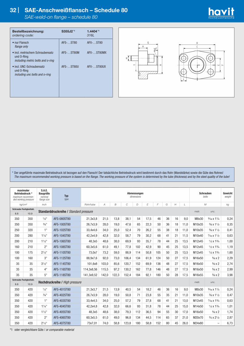
*1 oder vergleichbare Güte / or comparable material
Bestellbezeichnung:ordering code:
S355J2 *1
1.4404 *1
316L
• nur Flansch flange only
AFS-…ST80 AFX-…ST80
• incl. metrischem Schraubensatz und O-Ring including metric bolts and o-ring
AFS-…ST80M AFX-…ST80MX
• incl. UNC-Schraubensatz und O-Ring including unc bolts and o-ring
AFS-…ST80U AFX-…ST80UX
32 | SAE-Anschweißflansch – Schedule 80 SAE-weld-on flange – schedule 80
maximaler Betriebsdruck *
maximum recommen-ded working pressure
S.A.E. Baugröße
nominal flange size
Typtype
Abmessungendimensions
Schraubenbolts
Gewichtweight
kg/cm² inch Rohr/tube A B C D E F G H L M kg
Schraube Festigkeitskl.Standarddruckreihe / Standard pressure metr. unc.
8.8 10.9
350 350 ¹ ⁄₂" AFS-080ST80 21,3x3,8 21,5 13,8 38,1 54 17,5 46 36 16 9,0 M8x30 ⁵⁄₁₆ x 1¹⁄₄ 0,24
350 350 ³⁄₄" AFS-100ST80 26,7x3,9 28,0 19,0 47,6 65 22,3 50 36 18 11,0 M10x35 ³⁄₈ x 1¹ ⁄₂ 0,35
250 320 1" AFS-102ST80 33,4x4,6 34,0 25,0 52,4 70 26,2 55 38 18 11,0 M10x35 ³⁄₈ x 1¹ ⁄₂ 0,41
200 280 1¹⁄₄" AFS-104ST80 42,2x4,9 42,8 32,0 58,7 79 30,2 68 41 21 11,5 M10x40 ⁷⁄₁₆ x 1¹ ⁄₂ 0,63
200 210 1¹ ⁄₂" AFS-106ST80 48,3x5 48,6 38,0 69,9 93 35,7 78 44 25 13,5 M12x45 ¹ ⁄₂ x 1³⁄₄ 1,00
160 210 2" AFS-108ST80 60,3x5,6 61,0 49,1 77,8 102 42,9 90 45 25 13,5 M12x45 ¹ ⁄₂ x 1³⁄₄ 1,19
100 175 2¹ ⁄₂" AFS-110ST80 73,0x7 73,2 59,0 88,9 114 50,8 105 50 25 13,5 M12x45 ¹ ⁄₂ x 1³⁄₄ 1,60
100 160 3" AFS-112ST80 88,9x7,6 92,0 73,0 106,4 134 61,9 124 50 27 17,5 M16x50 ⁵⁄₈ x 2 2,29
35 35 3¹ ⁄₂" AFS-114ST80 101,6x8 103,0 85,6 120,7 152 69,9 136 48 27 17,5 M16x50 ⁵⁄₈ x 2 2,74
35 35 4" AFS-116ST80 114,3x8,56 115,5 97,2 130,2 162 77,8 146 48 27 17,5 M16x50 ⁵⁄₈ x 2 2,99
35 35 5" AFS-118ST80 141,3x9,52 142,0 122,3 152,4 184 92,1 180 50 28 17,5 M16x55 ⁵⁄₈ x 2 3,98Schraube Festigkeitskl.
Hochdruckreihe / High pressure metr. unc.8.8 10.9
350 420 ¹ ⁄₂" AFS-401ST80 21,3x3,7 21,5 13,9 40,5 54 18,2 46 36 16 9,0 M8x30 ⁵⁄₁₆ x 1¹⁄₄ 0,24
350 420 ³⁄₄" AFS-402ST80 26,7x3,9 28,0 19,0 50,8 71 23,8 55 35 21 11,0 M10x35 ³⁄₈ x 1¹ ⁄₂ 0,47
350 420 1" AFS-403ST80 33,4x4,5 34,0 25,0 57,2 79 27,8 68 41 21 13,0 M12x45 ⁷⁄₁₆ x 1³⁄₄ 0,63
350 420 1¹⁄₄" AFS-404ST80 42,2x4,8 42,8 32,0 66,6 93 31,8 78 44 25 15,0 M14x50 ¹ ⁄₂ x 1³⁄₄ 1,01
350 420 1¹ ⁄₂" AFS-405ST80 48,3x5 48,6 38,0 79,3 112 36,5 94 55 30 17,0 M16x50 ⁵⁄₈ x 2 1,74
350 420 2" AFS-406ST80 60,3x5,5 61,0 49,0 96,8 134 44,5 114 65 37 21,0 M20x70 ³⁄₄ x 2¹ ⁄₂ 2,87
350 420 2¹ ⁄₂" AFS-407ST80 73x7,01 74,0 58,8 123,8 180 58,8 152 80 45 26,0 M24x80 – 6,73
* Der angeführte maximale Betriebsdruck ist bezogen auf den Flansch! Der tatsächliche Betriebsdruck wird bestimmt durch das Rohr (Wandstärke) sowie die Güte des Rohres! The maximum recommended working pressure is based on the flange. The working pressure of the system is determined by the tube (thickness) and by the steel quality of the tube!
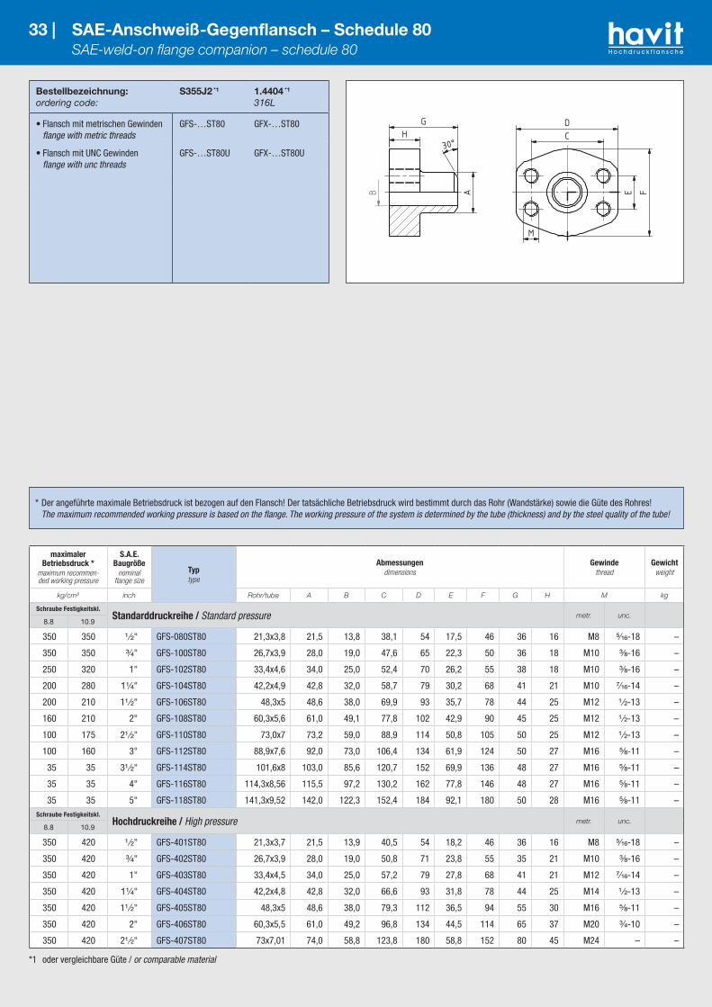
*1 oder vergleichbare Güte / or comparable material
Bestellbezeichnung:ordering code:
S355J2 *1
1.4404 *1
316L
• Flansch mit metrischen Gewinden flange with metric threads
GFS-…ST80 GFX-…ST80
• Flansch mit UNC Gewinden flange with unc threads
GFS-…ST80U GFX-…ST80U
33 | SAE-Anschweiß-Gegenflansch – Schedule 80 SAE-weld-on flange companion – schedule 80
maximaler Betriebsdruck *
maximum recommen-ded working pressure
S.A.E. Baugröße
nominal flange size
Typtype
Abmessungendimensions
Gewindethread
Gewichtweight
kg/cm² inch Rohr/tube A B C D E F G H M kg
Schraube Festigkeitskl.Standarddruckreihe / Standard pressure metr. unc.
8.8 10.9
350 350 ¹ ⁄₂" GFS-080ST80 21,3x3,8 21,5 13,8 38,1 54 17,5 46 36 16 M8 ⁵⁄₁₆-18 –
350 350 ³⁄₄" GFS-100ST80 26,7x3,9 28,0 19,0 47,6 65 22,3 50 36 18 M10 ³⁄₈-16 –
250 320 1" GFS-102ST80 33,4x4,6 34,0 25,0 52,4 70 26,2 55 38 18 M10 ³⁄₈-16 –
200 280 1¹⁄₄" GFS-104ST80 42,2x4,9 42,8 32,0 58,7 79 30,2 68 41 21 M10 ⁷⁄₁₆-14 –
200 210 1¹ ⁄₂" GFS-106ST80 48,3x5 48,6 38,0 69,9 93 35,7 78 44 25 M12 ¹ ⁄₂-13 –
160 210 2" GFS-108ST80 60,3x5,6 61,0 49,1 77,8 102 42,9 90 45 25 M12 ¹ ⁄₂-13 –
100 175 2¹ ⁄₂" GFS-110ST80 73,0x7 73,2 59,0 88,9 114 50,8 105 50 25 M12 ¹ ⁄₂-13 –
100 160 3" GFS-112ST80 88,9x7,6 92,0 73,0 106,4 134 61,9 124 50 27 M16 ⁵⁄₈-11 –
35 35 3¹ ⁄₂" GFS-114ST80 101,6x8 103,0 85,6 120,7 152 69,9 136 48 27 M16 ⁵⁄₈-11 –
35 35 4" GFS-116ST80 114,3x8,56 115,5 97,2 130,2 162 77,8 146 48 27 M16 ⁵⁄₈-11 –
35 35 5" GFS-118ST80 141,3x9,52 142,0 122,3 152,4 184 92,1 180 50 28 M16 ⁵⁄₈-11 –Schraube Festigkeitskl.
Hochdruckreihe / High pressure metr. unc.8.8 10.9
350 420 ¹ ⁄₂" GFS-401ST80 21,3x3,7 21,5 13,9 40,5 54 18,2 46 36 16 M8 ⁵⁄₁₆-18 –
350 420 ³⁄₄" GFS-402ST80 26,7x3,9 28,0 19,0 50,8 71 23,8 55 35 21 M10 ³⁄₈-16 –
350 420 1" GFS-403ST80 33,4x4,5 34,0 25,0 57,2 79 27,8 68 41 21 M12 ⁷⁄₁₆-14 –
350 420 1¹⁄₄" GFS-404ST80 42,2x4,8 42,8 32,0 66,6 93 31,8 78 44 25 M14 ¹ ⁄₂-13 –
350 420 1¹ ⁄₂" GFS-405ST80 48,3x5 48,6 38,0 79,3 112 36,5 94 55 30 M16 ⁵⁄₈-11 –
350 420 2" GFS-406ST80 60,3x5,5 61,0 49,2 96,8 134 44,5 114 65 37 M20 ³⁄₄-10 –
350 420 2¹ ⁄₂" GFS-407ST80 73x7,01 74,0 58,8 123,8 180 58,8 152 80 45 M24 – –
* Der angeführte maximale Betriebsdruck ist bezogen auf den Flansch! Der tatsächliche Betriebsdruck wird bestimmt durch das Rohr (Wandstärke) sowie die Güte des Rohres! The maximum recommended working pressure is based on the flange. The working pressure of the system is determined by the tube (thickness) and by the steel quality of the tube!
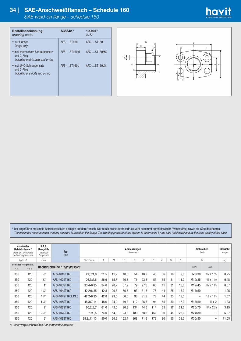
*1 oder vergleichbare Güte / or comparable material
Bestellbezeichnung:ordering code:
S355J2 *1
1.4404 *1
316L
• nur Flansch flange only
AFS-…ST160 AFX-…ST160
• incl. metrischem Schraubensatz und O-Ring including metric bolts and o-ring
AFS-…ST160M AFX-…ST160MX
• incl. UNC-Schraubensatz und O-Ring including unc bolts and o-ring
AFS-…ST160U AFX-…ST160UX
34 | SAE-Anschweißflansch – Schedule 160 SAE-weld-on flange – schedule 160
maximaler Betriebsdruck *
maximum recommen-ded working pressure
S.A.E. Baugröße
nominal flange size
Typtype
Abmessungendimensions
Schraubenbolts
Gewichtweight
kg/cm² inch Rohr/tube A B C D E F G H L M kg
Schraube Festigkeitskl.Hochdruckreihe / High pressure metr. unc.
8.8 10.9
350 420 ¹ ⁄₂" AFS-401ST160 21,3x4,8 21,5 11,7 40,5 54 18,2 46 36 16 9,0 M8x30 ⁵⁄₁₆ x 1¹⁄₄ 0,25
350 420 ³⁄₄" AFS-402ST160 26,7x5,6 26,9 15,7 50,8 71 23,8 55 35 21 11,0 M10x35 ³⁄₈ x 1¹ ⁄₂ 0,48
350 420 1" AFS-403ST160 33,4x6,35 34,0 20,7 57,2 79 27,8 68 41 21 13,0 M12x45 ⁷⁄₁₆ x 1³⁄₄ 0,67
350 420 1¹⁄₄" AFS-404ST160 42,2x6,35 42,8 29,5 66,6 93 31,8 78 44 25 15,0 M14x50 – 1,05
350 420 1¹⁄₄" AFS-404ST160L13,5 42,2x6,35 42,8 29,5 66,6 93 31,8 78 44 25 13,5 – ¹ ⁄₂ x 1³⁄₄ 1,07
350 420 1¹ ⁄₂" AFS-405ST160 48,3x7,14 48,6 34,0 79,3 112 36,5 94 55 30 17,0 M16x50 ⁵⁄₈ x 2 1,83
350 420 2" AFS-406ST160 60,3x8,7 61,0 43,0 96,8 134 44,5 114 65 37 21,0 M20x70 ³⁄₄ x 2¹ ⁄₂ 3,15
350 420 2¹ ⁄₂" AFS-407ST160 73x9,5 74,0 54,0 123,8 180 58,8 152 80 45 26,0 M24x80 – 6,97
350 420 3" AFS-408ST160 88,9x11,13 90,0 66,6 152,4 208 71,6 178 90 55 33,0 M30x90 – 11,05
* Der angeführte maximale Betriebsdruck ist bezogen auf den Flansch! Der tatsächliche Betriebsdruck wird bestimmt durch das Rohr (Wandstärke) sowie die Güte des Rohres! The maximum recommended working pressure is based on the flange. The working pressure of the system is determined by the tube (thickness) and by the steel quality of the tube!

*1 oder vergleichbare Güte / or comparable material
Bestellbezeichnung:ordering code:
S355J2 *1
1.4404 *1
316L
• Flansch mit metrischen Gewinden flange with metric threads
GFS-…ST160 GFX-…ST160
• Flansch mit UNC Gewinden flange with unc threads
GFS-…ST160U GFX-…ST160U
35 | SAE-Anschweiß-Gegenflansch – Schedule 160 SAE-weld-on flange companion – schedule 160
maximaler Betriebsdruck *
maximum recommen-ded working pressure
S.A.E. Baugröße
nominal flange size
Typtype
Abmessungendimensions
Schraubenbolts
Gewichtweight
kg/cm² inch Rohr/tube A B C D E F G H M kg
Schraube Festigkeitskl.Hochdruckreihe / High pressure metr. unc.
8.8 10.9
350 420 ¹ ⁄₂" GFS-401ST160 21,3x4,8 21,5 11,7 40,5 54 18,2 46 36 16 M8 ⁵⁄₁₆-18 –
350 420 ³⁄₄" GFS-402ST160 26,7x5,6 26,9 15,7 50,8 71 23,8 55 35 21 M10 ³⁄₈-16 –
350 420 1" GFS-403ST160 33,4x6,35 34,0 20,7 57,2 79 27,8 68 41 21 M12 ⁷⁄₁₆-14 –
350 420 1¹⁄₄" GFS-404ST160 42,2x6,35 42,8 29,5 66,6 93 31,8 78 44 25 M14 ¹ ⁄₂-13 –
350 420 1¹ ⁄₂" GFS-405ST160 48,3x7,14 48,6 34,0 79,3 112 36,5 94 55 30 M16 ⁵⁄₈-11 –
350 420 2" GFS-406ST160 60,3x8,7 61,0 43,0 96,8 134 44,5 114 65 37 M20 ³⁄₄-10 –
350 420 2¹ ⁄₂" GFS-407ST160 73x9,5 74,0 54,0 123,8 180 58,8 152 80 45 M24 – –
350 420 3" GFS-408ST160 88,9x11,13 90,0 66,6 152,4 208 71,6 178 90 55 M30 – –
* Der angeführte maximale Betriebsdruck ist bezogen auf den Flansch! Der tatsächliche Betriebsdruck wird bestimmt durch das Rohr (Wandstärke) sowie die Güte des Rohres! The maximum recommended working pressure is based on the flange. The working pressure of the system is determined by the tube (thickness) and by the steel quality of the tube!
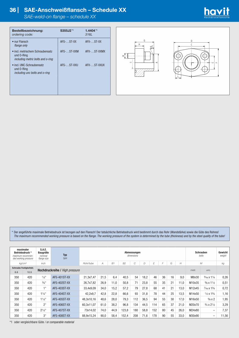
36 |
*1 oder vergleichbare Güte / or comparable material
Bestellbezeichnung:ordering code:
S355J2 *1
1.4404 *1
316L
• nur Flansch flange only
AFS-…ST-XX AFX-…ST-XX
• incl. metrischem Schraubensatz und O-Ring including metric bolts and o-ring
AFS-…ST-XXM AFX-…ST-XXMX
• incl. UNC-Schraubensatz und O-Ring including unc bolts and o-ring
AFS-…ST-XXU AFX-…ST-XXUX
36 | SAE-Anschweißflansch – Schedule XX SAE-weld-on flange – schedule XX
maximaler Betriebsdruck *
maximum recommen-ded working pressure
S.A.E. Baugröße
nominal flange size
Typtype
Abmessungendimensions
Schraubenbolts
Gewichtweight
kg/cm² inch Rohr/tube A B1 B2 C D E F G H M kg
Schraube Festigkeitskl.Hochdruckreihe / High pressure metr. unc.
8.8 10.9
350 420 ¹ ⁄₂" AFS-401ST-XX 21,3x7,47 21,5 6,4 40,5 54 18,2 46 36 16 9,0 M8x30 ⁵⁄₁₆ x 1¹⁄₄ 0,26
350 420 ³⁄₄" AFS-402ST-XX 26,7x7,82 26,9 11,0 50,8 71 23,8 55 35 21 11,0 M10x35 ³⁄₈ x 1¹ ⁄₂ 0,51
350 420 1" AFS-403ST-XX 33,4x9,09 34,0 15,2 57,2 79 27,8 68 41 21 13,0 M12x45 ⁷⁄₁₆ x 1³⁄₄ 0,72
350 420 1¹⁄₄" AFS-404ST-XX 42,2x9,7 42,8 22,8 66,6 93 31,8 78 44 25 13,5 M14x50 ¹ ⁄₂ x 1³⁄₄ 1,16
350 420 1¹ ⁄₂" AFS-405ST-XX 48,3x10,16 48,6 28,0 79,3 112 36,5 94 55 30 17,0 M16x50 ⁵⁄₈ x 2 1,95
350 420 2" AFS-406ST-XX 60,3x11,07 61,0 38,2 96,8 134 44,5 114 65 37 21,0 M20x70 ³⁄₄ x 2¹ ⁄₂ 3,29
350 420 2¹ ⁄₂" AFS-407ST-XX 73x14,02 74,0 44,9 123,8 180 58,8 152 80 45 26,0 M24x80 – 7,37
350 420 3" AFS-408ST-XX 88,9x15,24 90,0 58,4 152,4 208 71,6 178 90 55 33,0 M30x90 – 11,56
* Der angeführte maximale Betriebsdruck ist bezogen auf den Flansch! Der tatsächliche Betriebsdruck wird bestimmt durch das Rohr (Wandstärke) sowie die Güte des Rohres! The maximum recommended working pressure is based on the flange. The working pressure of the system is determined by the tube (thickness) and by the steel quality of the tube!
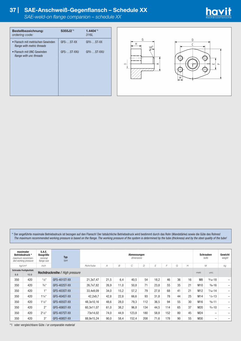
37 |
*1 oder vergleichbare Güte / or comparable material
Bestellbezeichnung:ordering code:
S355J2 *1
1.4404 *1
316L
• Flansch mit metrischen Gewinden flange with metric threads
GFS-…ST-XX GFX-…ST-XX
• Flansch mit UNC Gewinden flange with unc threads
GFS-…ST-XXU GFX-…ST-XXU
37 | SAE-Anschweiß-Gegenflansch – Schedule XX SAE-weld-on flange companion – schedule XX
maximaler Betriebsdruck *
maximum recommen-ded working pressure
S.A.E. Baugröße
nominal flange size
Typtype
Abmessungendimensions
Schraubenbolts
Gewichtweight
kg/cm² inch Rohr/tube A B C D E F G H M kg
Schraube Festigkeitskl.Hochdruckreihe / High pressure metr. unc.
8.8 10.9
350 420 ¹ ⁄₂" GFS-401ST-XX 21,3x7,47 21,5 6,4 40,5 54 18,2 46 36 16 M8 ⁵⁄₁₆-18 –
350 420 ³⁄₄" GFS-402ST-XX 26,7x7,82 26,9 11,0 50,8 71 23,8 55 35 21 M10 ³⁄₈-16 –
350 420 1" GFS-403ST-XX 33,4x9,09 34,0 15,2 57,2 79 27,8 68 41 21 M12 ⁷⁄₁₆-14 –
350 420 1¹⁄₄" GFS-404ST-XX 42,2x9,7 42,8 22,8 66,6 93 31,8 78 44 25 M14 ¹ ⁄₂-13 –
350 420 1¹ ⁄₂" GFS-405ST-XX 48,3x10,16 48,6 28,0 79,3 112 36,5 94 55 30 M16 ⁵⁄₈-11 –
350 420 2" GFS-406ST-XX 60,3x11,07 61,0 38,2 96,8 134 44,5 114 65 37 M20 ³⁄₄-10 –
350 420 2¹ ⁄₂" GFS-407ST-XX 73x14,02 74,0 44,9 123,8 180 58,8 152 80 45 M24 – –
350 420 3" GFS-408ST-XX 88,9x15,24 90,0 58,4 152,4 208 71,6 178 90 55 M30 – –
* Der angeführte maximale Betriebsdruck ist bezogen auf den Flansch! Der tatsächliche Betriebsdruck wird bestimmt durch das Rohr (Wandstärke) sowie die Güte des Rohres! The maximum recommended working pressure is based on the flange. The working pressure of the system is determined by the tube (thickness) and by the steel quality of the tube!
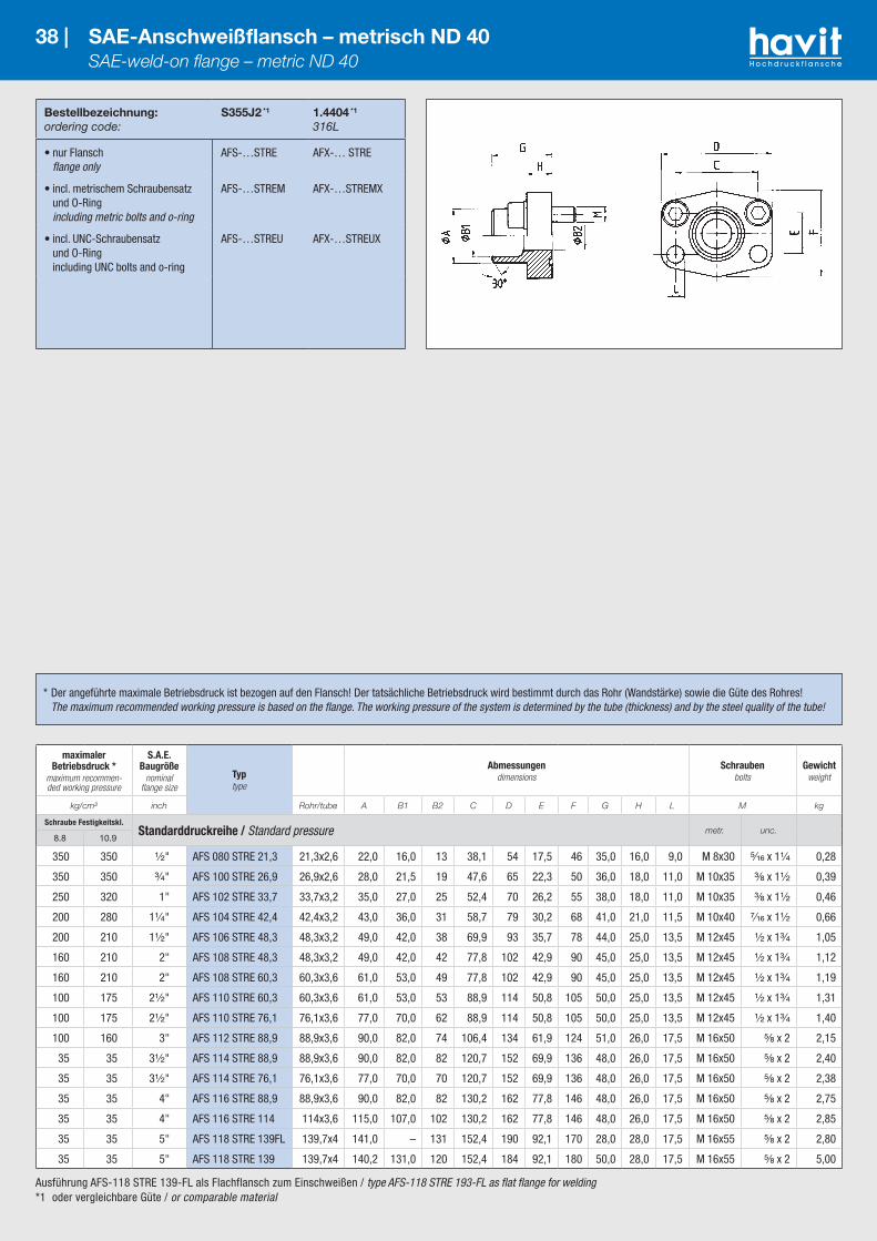
Ausführung AFS-118 STRE 139-FL als Flachflansch zum Einschweißen / type AFS-118 STRE 193-FL as flat flange for welding*1 oder vergleichbare Güte / or comparable material
Bestellbezeichnung:ordering code:
S355J2 *1
1.4404 *1
316L
• nur Flansch flange only
AFS-…STRE AFX-… STRE
• incl. metrischem Schraubensatz und O-Ring including metric bolts and o-ring
AFS-…STREM AFX-…STREMX
• incl. UNC-Schraubensatz und O-Ring including UNC bolts and o-ring
AFS-…STREU AFX-…STREUX
38 | SAE-Anschweißflansch – metrisch ND 40 SAE-weld-on flange – metric ND 40
maximaler Betriebsdruck *
maximum recommen-ded working pressure
S.A.E. Baugröße
nominal flange size
Typtype
Abmessungendimensions
Schraubenbolts
Gewichtweight
kg/cm² inch Rohr/tube A B1 B2 C D E F G H L M kg
Schraube Festigkeitskl.Standarddruckreihe / Standard pressure metr. unc.
8.8 10.9
350 350 ¹⁄₂" AFS 080 STRE 21,3 21,3x2,6 22,0 16,0 13 38,1 54 17,5 46 35,0 16,0 9,0 M 8x30 ⁵⁄₁₆ x 1¹⁄₄ 0,28
350 350 ³⁄₄" AFS 100 STRE 26,9 26,9x2,6 28,0 21,5 19 47,6 65 22,3 50 36,0 18,0 11,0 M 10x35 ³⁄₈ x 1¹⁄₂ 0,39
250 320 1" AFS 102 STRE 33,7 33,7x3,2 35,0 27,0 25 52,4 70 26,2 55 38,0 18,0 11,0 M 10x35 ³⁄₈ x 1¹⁄₂ 0,46
200 280 1¹⁄₄" AFS 104 STRE 42,4 42,4x3,2 43,0 36,0 31 58,7 79 30,2 68 41,0 21,0 11,5 M 10x40 ⁷⁄₁₆ x 1¹⁄₂ 0,66
200 210 1¹⁄₂" AFS 106 STRE 48,3 48,3x3,2 49,0 42,0 38 69,9 93 35,7 78 44,0 25,0 13,5 M 12x45 ¹⁄₂ x 1³⁄₄ 1,05
160 210 2" AFS 108 STRE 48,3 48,3x3,2 49,0 42,0 42 77,8 102 42,9 90 45,0 25,0 13,5 M 12x45 ¹⁄₂ x 1³⁄₄ 1,12
160 210 2" AFS 108 STRE 60,3 60,3x3,6 61,0 53,0 49 77,8 102 42,9 90 45,0 25,0 13,5 M 12x45 ¹⁄₂ x 1³⁄₄ 1,19
100 175 2¹⁄₂" AFS 110 STRE 60,3 60,3x3,6 61,0 53,0 53 88,9 114 50,8 105 50,0 25,0 13,5 M 12x45 ¹⁄₂ x 1³⁄₄ 1,31
100 175 2¹⁄₂" AFS 110 STRE 76,1 76,1x3,6 77,0 70,0 62 88,9 114 50,8 105 50,0 25,0 13,5 M 12x45 ¹⁄₂ x 1³⁄₄ 1,40
100 160 3" AFS 112 STRE 88,9 88,9x3,6 90,0 82,0 74 106,4 134 61,9 124 51,0 26,0 17,5 M 16x50 ⁵⁄₈ x 2 2,15
35 35 3¹⁄₂" AFS 114 STRE 88,9 88,9x3,6 90,0 82,0 82 120,7 152 69,9 136 48,0 26,0 17,5 M 16x50 ⁵⁄₈ x 2 2,40
35 35 3¹⁄₂" AFS 114 STRE 76,1 76,1x3,6 77,0 70,0 70 120,7 152 69,9 136 48,0 26,0 17,5 M 16x50 ⁵⁄₈ x 2 2,38
35 35 4" AFS 116 STRE 88,9 88,9x3,6 90,0 82,0 82 130,2 162 77,8 146 48,0 26,0 17,5 M 16x50 ⁵⁄₈ x 2 2,75
35 35 4" AFS 116 STRE 114 114x3,6 115,0 107,0 102 130,2 162 77,8 146 48,0 26,0 17,5 M 16x50 ⁵⁄₈ x 2 2,85
35 35 5" AFS 118 STRE 139FL 139,7x4 141,0 – 131 152,4 190 92,1 170 28,0 28,0 17,5 M 16x55 ⁵⁄₈ x 2 2,80
35 35 5" AFS 118 STRE 139 139,7x4 140,2 131,0 120 152,4 184 92,1 180 50,0 28,0 17,5 M 16x55 ⁵⁄₈ x 2 5,00
* Der angeführte maximale Betriebsdruck ist bezogen auf den Flansch! Der tatsächliche Betriebsdruck wird bestimmt durch das Rohr (Wandstärke) sowie die Güte des Rohres! The maximum recommended working pressure is based on the flange. The working pressure of the system is determined by the tube (thickness) and by the steel quality of the tube!

Ausführung AFS-118 STRE 139-FL als Flachflansch zum Einschweißen / type AFS-118 STRE 193-FL as flat flange for welding*1 oder vergleichbare Güte / or comparable material
Bestellbezeichnung:ordering code:
S355J2 *1
1.4404 *1
316L
• nur Flansch flange only
GFS-…STRE GFX-…STRE
39 | SAE-Anschweiß-Gegenflansch – metrisch ND 40 SAE-weld-on flange companion – metric ND 40
maximaler Betriebsdruck *
maximum recommen-ded working pressure
S.A.E. Baugröße
nominal flange size
Typtype
Abmessungendimensions
Gewindethread
Gewichtweight
kg/cm² inch Rohr/tube A B1 B2 C D E F G H M kg
Schraube Festigkeitskl.Standarddruckreihe / Standard pressure
8.8 10.9
350 350 ¹ ⁄₂" GFS 080 STRE 21,3 21,3x2,6 22,0 16,0 13 38,1 54 17,5 46 35,0 16,0 M 8 0,28
350 350 ³⁄₄" GFS 100 STRE 26,9 26,9x2,6 28,0 21,5 19 47,6 65 22,3 50 36,0 18,0 M 10 0,39
250 320 1" GFS 102 STRE 33,7 33,7x3,2 35,0 27,0 25 52,4 70 26,2 55 38,0 18,0 M 10 0,46
200 280 1¹⁄₄" GFS 104 STRE 42,4 42,4x3,2 43,0 36,0 31 58,7 79 30,2 68 41,0 21,0 M 10 0,66
200 210 1¹ ⁄₂" GFS 106 STRE 48,3 48,3x3,2 49,0 42,0 38 69,9 93 35,7 78 44,0 25,0 M 12 1,05
160 210 2" GFS 108 STRE 48,3 48,3x3,2 49,0 42,0 42 77,8 102 42,9 90 45,0 25,0 M 12 1,20
160 210 2" GFS 108 STRE 60,3 60,3x3,6 61,0 53,0 49 77,8 102 42,9 90 45,0 25,0 M 12 1,25
100 175 2¹ ⁄₂" GFS 110 STRE 60,3 60,3x3,6 61,0 53,0 53 88,9 114 50,8 105 50,0 25,0 M 12 1,29
100 175 2¹ ⁄₂" GFS 110 STRE 76,1 76,1x3,6 77,0 70,0 62 88,9 114 50,8 105 50,0 25,0 M 12 1,40
100 160 3" GFS 112 STRE 88,9 88,9x3,6 90,0 82,0 74 106,4 134 61,9 124 51,0 26,0 M 16 2,15
35 35 3¹ ⁄₂" GFS 114 STRE 88,9 88,9x3,6 90,0 82,0 82 120,7 152 69,9 136 48,0 26,0 M 16 2,40
35 35 3¹ ⁄₂" GFS 114 STRE 76,1 76,1x3,6 77,0 70,0 70 120,7 152 69,9 136 48,0 26,0 M 16 2,40
35 35 4" GFS 116 STRE 88,9 88,9x3,6 90,0 82,0 82 130,2 162 77,8 146 48,0 26,0 M 16 2,69
35 35 4" GFS 116 STRE 114 114,3x3,6 115,0 107,0 102 130,2 162 77,8 146 48,0 26,0 M 16 2,85
35 35 5" GFS 118 STRE 139FL 139,7x4 141,0 – 131 152,4 190 92,1 170 28,0 28,0 M 16 2,80
35 35 5" GFS 118 STRE 139 139,7x4 140,2 131,0 120 152,4 184 92,1 180 50,0 28,0 M 16 5,00
* Der angeführte maximale Betriebsdruck ist bezogen auf den Flansch! Der tatsächliche Betriebsdruck wird bestimmt durch das Rohr (Wandstärke) sowie die Güte des Rohres! The maximum recommended working pressure is based on the flange. The working pressure of the system is determined by the tube (thickness) and by the steel quality of the tube!
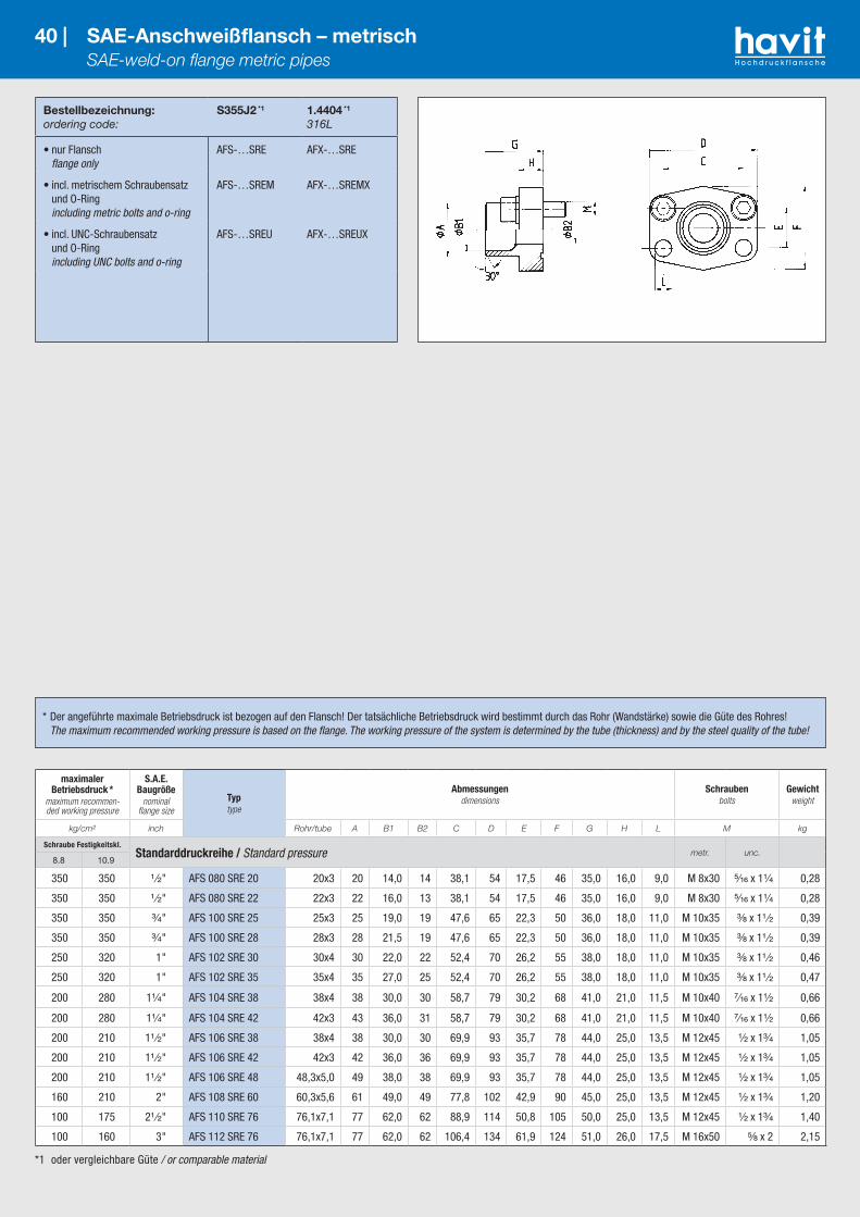
*1 oder vergleichbare Güte / or comparable material
Bestellbezeichnung:ordering code:
S355J2 *1
1.4404 *1
316L
• nur Flansch flange only
AFS-…SRE AFX-…SRE
• incl. metrischem Schraubensatz und O-Ring including metric bolts and o-ring
AFS-…SREM AFX-…SREMX
• incl. UNC-Schraubensatz und O-Ring including UNC bolts and o-ring
AFS-…SREU AFX-…SREUX
40 | SAE-Anschweißflansch – metrisch SAE-weld-on flange metric pipes
maximaler Betriebsdruck *
maximum recommen-ded working pressure
S.A.E. Baugröße
nominal flange size
Typtype
Abmessungendimensions
Schraubenbolts
Gewichtweight
kg/cm² inch Rohr/tube A B1 B2 C D E F G H L M kg
Schraube Festigkeitskl.Standarddruckreihe / Standard pressure metr. unc.
8.8 10.9
350 350 ¹ ⁄₂" AFS 080 SRE 20 20x3 20 14,0 14 38,1 54 17,5 46 35,0 16,0 9,0 M 8x30 ⁵⁄₁₆ x 1¹⁄₄ 0,28
350 350 ¹ ⁄₂" AFS 080 SRE 22 22x3 22 16,0 13 38,1 54 17,5 46 35,0 16,0 9,0 M 8x30 ⁵⁄₁₆ x 1¹⁄₄ 0,28
350 350 ³⁄₄" AFS 100 SRE 25 25x3 25 19,0 19 47,6 65 22,3 50 36,0 18,0 11,0 M 10x35 ³⁄₈ x 1¹ ⁄₂ 0,39
350 350 ³⁄₄" AFS 100 SRE 28 28x3 28 21,5 19 47,6 65 22,3 50 36,0 18,0 11,0 M 10x35 ³⁄₈ x 1¹ ⁄₂ 0,39
250 320 1" AFS 102 SRE 30 30x4 30 22,0 22 52,4 70 26,2 55 38,0 18,0 11,0 M 10x35 ³⁄₈ x 1¹ ⁄₂ 0,46
250 320 1" AFS 102 SRE 35 35x4 35 27,0 25 52,4 70 26,2 55 38,0 18,0 11,0 M 10x35 ³⁄₈ x 1¹ ⁄₂ 0,47
200 280 1¹⁄₄" AFS 104 SRE 38 38x4 38 30,0 30 58,7 79 30,2 68 41,0 21,0 11,5 M 10x40 ⁷⁄₁₆ x 1¹⁄₂ 0,66
200 280 1¹⁄₄" AFS 104 SRE 42 42x3 43 36,0 31 58,7 79 30,2 68 41,0 21,0 11,5 M 10x40 ⁷⁄₁₆ x 1¹⁄₂ 0,66
200 210 1¹ ⁄₂" AFS 106 SRE 38 38x4 38 30,0 30 69,9 93 35,7 78 44,0 25,0 13,5 M 12x45 ¹⁄₂ x 1³⁄₄ 1,05
200 210 1¹ ⁄₂" AFS 106 SRE 42 42x3 42 36,0 36 69,9 93 35,7 78 44,0 25,0 13,5 M 12x45 ¹⁄₂ x 1³⁄₄ 1,05
200 210 1¹ ⁄₂" AFS 106 SRE 48 48,3x5,0 49 38,0 38 69,9 93 35,7 78 44,0 25,0 13,5 M 12x45 ¹⁄₂ x 1³⁄₄ 1,05
160 210 2" AFS 108 SRE 60 60,3x5,6 61 49,0 49 77,8 102 42,9 90 45,0 25,0 13,5 M 12x45 ¹⁄₂ x 1³⁄₄ 1,20
100 175 2¹ ⁄₂" AFS 110 SRE 76 76,1x7,1 77 62,0 62 88,9 114 50,8 105 50,0 25,0 13,5 M 12x45 ¹⁄₂ x 1³⁄₄ 1,40
100 160 3" AFS 112 SRE 76 76,1x7,1 77 62,0 62 106,4 134 61,9 124 51,0 26,0 17,5 M 16x50 ⁵⁄₈ x 2 2,15
* Der angeführte maximale Betriebsdruck ist bezogen auf den Flansch! Der tatsächliche Betriebsdruck wird bestimmt durch das Rohr (Wandstärke) sowie die Güte des Rohres! The maximum recommended working pressure is based on the flange. The working pressure of the system is determined by the tube (thickness) and by the steel quality of the tube!

*1 oder vergleichbare Güte / or comparable material
Bestellbezeichnung:ordering code:
S355J2 *1
1.4404 *1
316L
• nur Flansch flange only
AFS-…SRE AFX-…SRE
• incl. metrischem Schraubensatz und O-Ring including metric bolts and o-ring
AFS-…SREM AFX-…SREMX
• incl. UNC-Schraubensatz und O-Ring including UNC bolts and o-ring
AFS-…SREU AFX-…SREUX
41 | SAE-Anschweißflansch – metrisch SAE-weld-on flange metric pipes
maximaler Betriebsdruck *
maximum recommen-ded working pressure
S.A.E. Baugröße
nominal flange size
Typtype
Abmessungendimensions
Schraubenbolts
Gewichtweight
kg/cm² inch Rohr/tube A B1 B2 C D E F G H L M kg
Schraube Festigkeitskl.Hochdruckreihe / High pressure metr. unc.
8.8 10.9
350 420 ¹ ⁄₂" AFS 401 SRE 20 20x3 20 14 14 40,5 54 18,2 46 34 16 9 M 8x30 ⁵⁄₁₆ x 1¹⁄₄ 0,29
350 420 ³⁄₄" AFS 402 SRE 20 20x3 20 14 14 50,8 71 23,8 55 35 21 11 M 10x35 ³⁄₈ x 1¹ ⁄₂ 0,50
350 420 ³⁄₄" AFS 402 SRE 25 25x4 25 17 17 50,8 71 23,8 55 35 21 11 M 10x35 ³⁄₈ x 1¹ ⁄₂ 0,53
350 420 1" AFS 403 SRE 25 25x4 25 17 17 57,2 81 27,8 65 42 25 13 M 12x45 ⁷⁄₁₆ x 1¹ ⁄₂ 0,76
350 420 1" AFS 403 SRE 30 30x4 30 22 22 57,2 81 27,8 65 42 25 13 M 12x45 ⁷⁄₁₆ x 1¹ ⁄₂ 0,80
350 420 1¹⁄₄" AFS 404 SRE 30 30x4 30 22 22 66,6 95 31,8 78 44 25 15 M 14x50 ¹⁄₂ x 1³⁄₄ 1,20
350 420 1¹⁄₄" AFS 404 SRE 38 38x6 38 26 26 66,6 95 31,8 78 44 25 15 M 14x50 ¹⁄₂ x 1³⁄₄ 1,29
350 420 1¹ ⁄₂" AFS 405 SRE 38 38x6 38 26 26 79,3 112 36,5 94 56 28 17 M 16x50 ⁵⁄₈ x 2 1,52
350 420 1¹ ⁄₂" AFS 405 SRE 48 48,3x8 49 32 32 79,3 112 36,5 94 56 28 17 M 16x50 ⁵⁄₈ x 2 1,57
350 420 1¹ ⁄₂" AFS 405 SRE 60 60,3x10 61 40 38 79,3 112 36,5 94 56 28 17 M 16x50 ⁵⁄₈ x 2 1,65
350 420 2" AFS 406 SRE 60 60,3x10 61 40 40 96,8 134 44,5 114 65 37 21 M 20x70 ³⁄₄ x 2¹ ⁄₂ 2,45
350 420 2" AFS 406 SRE 76 76,1x12,5 77 51 48 96,8 134 44,5 114 80 33 21 M 20x65 ³⁄₄ x 2¹ ⁄₂ 2,96
* Der angeführte maximale Betriebsdruck ist bezogen auf den Flansch! Der tatsächliche Betriebsdruck wird bestimmt durch das Rohr (Wandstärke) sowie die Güte des Rohres! The maximum recommended working pressure is based on the flange. The working pressure of the system is determined by the tube (thickness) and by the steel quality of the tube!

*1 oder vergleichbare Güte / or comparable material
Bestellbezeichnung:ordering code:
S355J2 *1
1.4404 *1
316L
• nur Flansch flange only
GFS-…SRE GFX-…SRE
42 | SAE-Anschweiß-Gegenflansch – metrisch SAE-weld-on flange-metric pipes – companion
* Der angeführte maximale Betriebsdruck ist bezogen auf den Flansch! Der tatsächliche Betriebsdruck wird bestimmt durch das Rohr (Wandstärke) sowie die Güte des Rohres! The maximum recommended working pressure is based on the flange. The working pressure of the system is determined by the tube (thickness) and by the steel quality of the tube!
maximaler Betriebsdruck *
maximum recommen-ded working pressure
S.A.E. Baugröße
nominal flange size
Typtype
Abmessungendimensions
Gewindethread
Gewichtweight
kg/cm² inch Rohr/tube A B1 B2 C D E F G H M kg
Schraube Festigkeitskl.Standarddruckreihe / Standard pressure
8.8 10.9
350 350 ¹ ⁄₂" GFS 080 SRE 20 20x3 20 14,0 14 38,1 54 17,5 46 35,0 16,0 M 8 0,28
350 350 ¹ ⁄₂" GFS 080 SRE 22 22x3 22 16,0 13 38,1 54 17,5 46 35,0 16,0 M 8 0,28
350 350 ³⁄₄" GFS 100 SRE 25 25x3 25 19,0 19 47,6 65 22,3 50 36,0 18,0 M 10 0,39
350 350 ³⁄₄" GFS 100 SRE 28 28x3 28 21,5 19 47,6 65 22,3 50 36,0 18,0 M 10 0,39
250 320 1" GFS 102 SRE 30 30x4 30 22,0 22 52,4 70 26,2 55 38,0 18,0 M 10 0,46
250 320 1" GFS 102 SRE 35 35x4 35 27,0 25 52,4 70 26,2 55 38,0 18,0 M 10 0,47
200 280 1¹⁄₄" GFS 104 SRE 38 38x4 38 30,0 30 58,7 79 30,2 68 41,0 21,0 M 10 0,66
200 280 1¹⁄₄" GFS 104 SRE 42 42x3 43 36,0 31 58,7 79 30,2 68 41,0 21,0 M 10 0,66
200 210 1¹ ⁄₂" GFS 106 SRE 38 38x4 38 30,0 30 69,9 93 35,7 78 44,0 25,0 M 12 1,05
200 210 1¹ ⁄₂" GFS 106 SRE 42 42x3 42 36,0 36 69,9 93 35,7 78 44,0 25,0 M 12 1,05
200 210 1¹ ⁄₂" GFS 106 SRE 48 48,3x5,0 49 38,0 38 69,9 93 35,7 78 44,0 25,0 M 12 1,05
160 210 2" GFS 108 SRE 60 60,3x5,6 61 49,0 49 77,8 102 42,9 90 45,0 25,0 M 12 1,20
100 175 2¹ ⁄₂" GFS 110 SRE 76 76,1x7,1 77 62,0 62 88,9 114 50,8 105 50,0 25,0 M 12 1,40
100 160 3" GFS 112 SRE 76 76,1x7,1 77 62,0 62 106,4 134 61,9 125 51,0 26,0 M 16 2,15Schraube Festigkeitskl.
Hochdruckreihe / High pressure8.8 10.9
350 420 ¹ ⁄₂" GFS 401 SRE 20 20x3 20 14,0 14 40,5 54 18,2 46 34,0 16,0 M 8 0,29
350 420 ³⁄₄" GFS 402 SRE 20 20x3 20 14,0 14 50,8 71 23,8 55 35,0 21,0 M 10 0,50
350 420 ³⁄₄" GFS 402 SRE 25 25x4 25 17,0 17 50,8 71 23,8 55 35,0 21,0 M 10 0,53
350 420 1" GFS 403 SRE 25 25x4 25 17,0 17 57,2 81 27,8 65 42,0 25,0 M 12 0,76
350 420 1" GFS 403 SRE 30 30x4 30 22,0 22 57,2 81 27,8 65 42,0 25,0 M 12 0,80
350 420 1¹⁄₄" GFS 404 SRE 30 30x4 30 22,0 22 66,6 95 31,8 78 44,0 25,0 M 14 1,20
350 420 1¹⁄₄" GFS 404 SRE 38 38x6 38 26,0 26 66,6 95 31,8 78 44,0 25,0 M 14 1,29
350 420 1¹ ⁄₂" GFS 405 SRE 38 38x6 38 26,0 26 79,3 112 36,5 94 56,0 28,0 M 16 1,52
350 420 1¹ ⁄₂" GFS 405 SRE 48 48,3x8 49 32,0 32 79,3 112 36,5 94 56,0 28,0 M 16 1,57
350 420 1¹ ⁄₂" GFS 405 SRE 60 60,3x10 61 40,0 38 79,3 112 36,5 94 56,0 28,0 M 16 1,65
350 420 2" GFS 406 SRE 60 60,3x10 61 40,0 40 96,8 134 44,5 114 65,0 37,0 M 20 2,45
350 420 2" GFS 406 SRE 76 76,1x12,5 77 51,0 48 96,8 134 44,5 114 80,0 33,0 M 20 2,96

*1 oder vergleichbare Güte / or comparable material*2 Rohrdurchmesser 76,1 gemäß ISO 6162 max. 74 mm / Pipe diameter 76.1 according to ISO 6162 max. 74 mm
43 | SAE-Anschweißbund SAE-Flange head
Bestellbezeichnung:ordering code:
S355J2 *1
1.4404 *1
316L
• nur Anschweißbund flange head only
SFS-… SFX-…
• Anschweißflansch mit Zubehör incl. Flansch-hälften (oder Vollflansch), metrischem Schraubensatz und O-Ring weld-on flange with acessories including split flanges (or complete flange), metric bolts and o-ring
SFS-…M SFX-…MX
• Anschweißflansch mit Zubehör incl. Flansch-hälften (oder Vollflansch), UNC-Schraubensatz und O-Ring including split flanges (or complete flange), UNC-bolts and o-ring
SFS-…U SFX-…UX
Bestellbezeichnung für Anschweißbund in Gegenflanschausführung (ohne O-Ringnut): Ordering code flange head as counterflange (without o-ring groove).
• nur Anschweißbund ohne Nut flange head without o-ring groove
GSFS-… GSFX-…
maximaler Betriebsdruck *
maximum recommen-ded working pressure
S.A.E. Baugröße
nominal flange size
Typtype
Abmessungendimensions
Schraubenbolts
Gewichtweight
kg/cm² inch C D E F G L M kg
Schraube Festigkeitskl.Standarddruckreihe / Standard pressure metr. unc.
8.8 10.9
350 350 ¹ ⁄₂" SFS 3001 38,1 54 17,5 45,6 41 8,75 M 8x25 ⁵⁄₁₆ x 1¹⁄₄ 0,08
A x S = 16 x 2 – 20 x 2,5 – 21,3 x 2,9 – 21,3 x 3,8 – 21,3 x 4,7
350 350 ³⁄₄" SFS 3002 47,6 65 22,3 51,8 50 10,75 M 10x30 ³⁄₈ x 1¹⁄₄ 0,16
A x S = 25 x 3 – 26,9 x 3,6 – 26,9 x 3,9
250 320 1" SFS 3003 52,4 70 26,2 58,4 50 10,75 M 10x30 ³⁄₈ x 1¹⁄₄ 0,23
A x S = 25 x 3 – 28 x 3 – 30 x 3 – 30 x 4 – 33,7 x 4,5 – 38 x 4 – 38 x 5
200 280 1¹⁄₄" SFS 3004 58,7 79 30,2 72,6 5510,75
12,75
M 10x30**
M 12x35⁷⁄₁₆ x 1¹ ⁄₂ 0,30
A x S = 25 x 3 – 30 x 3 – 38 x 3 – 38 x 4 – 38 x 5 – 42,4 x 3,6 – 42,4 x 4,5 – 42,4 x 6,3
200 210 1¹ ⁄₂" SFS 3005 69,9 94 35,7 82,2 57 13,50 M 12x35 ¹ ⁄₂ x 1¹ ⁄₂ 0,40
A x S = 38 x 4 – 42 x 3 – 42 x 5 – 45 x 5 – 48,3 x 2,6 – 48,3 x 3,6 – 48,3 x 5 – 48,3 x 6,3 – 48,3 x 7,1– 50 x 6
160 210 2" SFS 3006 77,8 102 42,9 96,4 57 13,50 M 12x35 ¹ ⁄₂ x 1¹ ⁄₂ 0,50
A x S = 48,3 x 5 – 55 x 5 – 60,3 x 2,9 – 60,3 x 3,9 – 60,3 x 5 – 60,3 x 6,3 – 60,3 x 8
100 175 2¹ ⁄₂" SFS 3007 88,9 114 50,8 108,2 58 13,50 M 12x40 ¹ ⁄₂ x 1³⁄₄ 0,80
A x S = 65 x 6 – 70 x 7,5 – 76,1x 5,5 (74 x 4,5) *2 – 76,1x 7,1(74 x 6,1) *2
100 160 3" SFS 3008 106,4 135 61,9 130,6 58 17,00 M 16x50 ⁵⁄₈ x 2 1,10
A x S = 80 x 6 – 88,9 x 3,2 – 88,9 x 3,9 – 88,9 x 7 – 88,9 x 8
35 35 3¹ ⁄₂" SFS 3009 120,7 152 69,9 139,0 60 17,00 M 16x50 ⁵⁄₈ x 2 1,40
A x S = 100 x 6 – 88,9 x 3,6 – 88,9 x 8
35 35 4" SFS 3010 130,2 162 77,8 152,0 60 17,00 M 16x50 ⁵⁄₈ x 2 1,75
A x S = 110 x 6 – 114,3 x 3,6 – 114,3 x 6,02 – 114,3 x 8,8
35 35 5" SFS 3011 152,4 184 92,1 180,0 60 17,00 M 16x55 ⁵⁄₈ x 2 2,62
A x S = 133 x 6,5 – 139,7 x 4 – 139,7 x 10
* Der angeführte maximale Betriebsdruck ist bezogen auf den Flansch! Der tatsächliche Betriebsdruck wird bestimmt durch das Rohr (Wand- stärke) sowie die Güte des Rohres! The maximum recommended working pressure is based on the flange. The working pressure of the system is determined by the tube (thickness) and by the steel quality of the tube!
** bitte angeben: M10 oder M12 Schrauben
please state: bolts M10 or M12

*1 oder vergleichbare Güte / or comparable material
Bestellbezeichnung:ordering code:
S355J2 *1
1.4404 *1
316L
• nur Anschweißbund flange head only
SFS-… SFX-…
• Anschweißflansch mit Zubehör incl. Flansch-hälften (oder Vollflansch), metrischem Schraubensatz und O-Ring weld-on flange with acessories including split flanges (or complete flange), metric bolts and o-ring
SFS-…M SFX-…MX
• Anschweißflansch mit Zubehör incl. Flansch-hälften (oder Vollflansch), UNC-Schraubensatz und O-Ring weld-on flange with acessories including split flanges (or complete flange), UNC-bolts and o-ring
SFS-…U SFX-…UX
Bestellbezeichnung für Anschweißbund in Gegenflanschausführung (ohne O-Ringnut): Ordering code flange head as counterflange (without o-ring groove).
• nur Anschweißbund ohne Nut flange head without o-ring groove
GSFS-… GSFX-…
44 | SAE-Anschweißbund SAE-Flange head
maximaler Betriebsdruck *
maximum recommen-ded working pressure
S.A.E. Baugröße
nominal flange size
Typtype
Abmessungendimensions
Schraubenbolts
Gewichtweight
kg/cm² inch C D E F G L M kg
Schraube Festigkeitskl.Hochdruckreihe / High pressure metr. unc.
8.8 10.9
350 420 ¹ ⁄₂" SFS 6001 40,5 56 18,2 47,2 34 8,75 M 8x30 ⁵⁄₁₆ x 1¹⁄₄ 0,08
A x S = 16 x 2 – 20 x 2,5 – 21,3 x 3,8 – 21,3 x 4,5
350 420 ³⁄₄" SFS 6002 50,8 71 23,8 60,0 38 10,75 M 10x35 ³⁄₈ x 1¹ ⁄₂ 0,17
A x S = 16 x 2 – 20 x 2,5 – 25 x 3 – 25 x 3,5 – 25 x 4 – 26,9 x 5,6
350 420 1" SFS 6003 57,2 81 27,8 69,6 40 13/12 M 12x45 ⁷⁄₁₆ x 1³⁄₄ 0,25
A x S = 25 x 3 – 30 x 3 – 30 x 4 – 33,7 x 6,3 – 33,7 x 7,1– 38 x 4 – 38 x 5
350 420 1¹⁄₄" SFS 6004 66,6 95 31,8 77,2 45 14,75/13,5 M 14x50 ¹ ⁄₂ x 1³⁄₄ 0,30
A x S = 25 x 3 – 30 x 4 – 38 x 4 – 38 x 5 – 38 x 5,5 – 38 x 6 – 42,4 x 6,3
350 420 1¹ ⁄₂" SFS 6005 79,3 113 36,5 95,0 50 17,00 M 16x55 ⁵⁄₈ x 2 0,53
A x S = 38 x 5 – 45 x 6,5 – 48,3 x 5 – 48,3 x 6,3 – 48,3 x 7,1– 48,3 x 8 – 48,3 x 8,8 – 50 x 6
350 420 2" SFS 6006 96,8 133 44,5 113,8 58 21/20 M 20x70 ³⁄₄ x 2¹ ⁄₂ 0,90
A x S = 48,3 x 6,3 – 60,3 x 6,3 – 60,3 x 7,5 – 60,3 x 8 – 60,3 x 8,75 – 60,3 x 10 – 60,3 x 13,4 – 65x8
350 420 2¹ ⁄₂" SFS 6007 123,8 180 58,8 150,2 75 26,00 M 24x80 – 2,40
A x S = 76,1 x 8 – 76,1 x 10 – 76,1 x 12,5 – 88,9 x 10 – 88,9 x 11,1– 88,9 x 14,2 – 88,9 x 17
350 420 3" SFS 6008 152,4 215 71,6 198,2 80 32,00 M 30x90 – 3,60
A x S = 88,9 x 10 – 88,9 x 11,1– 88,9 x 14,2 – 114,3 x 11– 114,3 x 17,5
* Der angeführte maximale Betriebsdruck ist bezogen auf den Flansch! Der tatsächliche Betriebsdruck wird bestimmt durch das Rohr (Wandstärke) sowie die Güte des Rohres! The maximum recommended working pressure is based on the flange. The working pressure of the system is determined by the tube (thickness) and by the steel quality of the tube!

*1 oder vergleichbare Güte / or comparable material*2 Rohrdurchmesser 76,1 gemäß ISO 6162 max. 74 mm / Pipe diameter 76.1 according to ISO 6162 max. 74 mm
Bestellbezeichnung:ordering code:
S355J2 *1
1.4404 *1
316L
• Anschweißdoppelflansch welding head-coupling
DSFS DSFX
45 | SAE-Anschweißdoppelflansch SAE-welding head-coupling
maximaler Betriebsdruck *
maximum recommen-ded working pressure
S.A.E. Baugröße
nominal flange size
Typtype
Abmessungendimensions
Schraubenbolts
Gewichtweight
kg/cm² inch C D E F G L M kg
Schraube Festigkeitskl.Standarddruckreihe / Standard pressure metr. unc.
8.8 10.9
350 350 ¹ ⁄₂" DSFS 3001 38,1 54 17,5 45,6 82 8,75 M 8x30 ⁵⁄₁₆ x 1¹⁄₄ 0,50
A x S = 16 x 2 – 20 x 2,5 – 21,3 x 2,9 – 21,3 x 3,8 – 21,3 x 4,7
350 350 ³⁄₄" DSFS 3002 47,6 65 22,3 51,8 100 10,75 M 10x30 ³⁄₈ x 1¹⁄₄ 0,80
A x S = 25 x 3 – 26,9 x 3,6 – 26,9 x 3,9
250 320 1" DSFS 3003 52,4 70 26,2 58,4 100 10,75 M 10x35 ³⁄₈ x 1¹⁄₄ 1,10
A x S = 25 x 3 – 30 x 3 – 30 x 4 – 33,7 x 4,5 – 38 x 4 – 38 x 5
200 280 1¹⁄₄" DSFS 3004 58,7 79 30,2 72,6 11010,75
12,75
M 10x35**
M 12x40 ⁷⁄₁₆ x 1¹ ⁄₂1,50
A x S = 25 x 3 – 30 x 3 – 38 x 3 – 38 x 4 – 38 x 5 – 42,4 x 3,6 – 42,4 x 4,5 – 42,4 x 6,3
200 210 1¹ ⁄₂" DSFS 3005 69,9 94 35,7 82,2 114 13,50 M 12x35 ¹ ⁄₂ x 1¹ ⁄₂ 2,20
A x S = 38 x 4 – 42 x 3 – 42 x 5 – 45 x 5 – 48,3 x 2,6 – 48,3 x 3,6 – 48,3 x 5 – 48,3 x 6,3 – 48,3 x 7,1– 50 x 6
160 210 2" DSFS 3006 77,8 102 42,9 96,4 114 13,50 M 12x35 ¹ ⁄₂ x 1¹ ⁄₂ 2,40
A x S = 48,3 x 5 – 55 x 5 – 60,3 x 2,9 – 60,3 x 3,9 – 60,3 x 5 – 60,3 x 6,3 – 60,3 x 8
100 175 2¹ ⁄₂" DSFS 3007 88,9 114 50,8 108,2 116 13,50 M 12x45 ¹ ⁄₂ x 1³⁄₄ 3,50
A x S = 65 x 6 – 70 x 7,5 – 76,1 x 5,5 (74 x 4,5) *2 – 76,1 x 7,1 (74 x 6,1) *2
100 160 3" DSFS 3008 106,4 135 61,9 130,6 116 17,00 M 16x50 ⁵⁄₈ x 2 5,30
A x S = 80 x 6 – 88,9 x 3,2 – 88,9 x 3,6 – 88,9 x 7 – 88,9 x 8
35 35 3¹ ⁄₂" DSFS 3009 120,7 152 69,9 139,0 120 17,00 M 16x50 ⁵⁄₈ x 2 5,30
A x S = 100 x 6 – 88,9 x 3,6 – 88,9 x 8
35 35 4" DSFS 3010 130,2 162 77,8 152,0 120 17,00 M 16x55 ⁵⁄₈ x 2 7,50
A x S = 110 x 6 – 114,3 x 3,6 – 114,3 x 6,02 – 114,3 x 8,8
35 35 5" DSFS 3011 152,4 184 92,1 180,0 120 17,00 M 16x60 ⁵⁄₈ x 2 11,0
A x S = 133 x 6,5 – 139,7 x 4 – 139,7 x 10
** bitte angeben: M10 oder M12 Schrauben
please state: bolts M10 or M12
* Der angeführte maximale Betriebsdruck ist bezogen auf den Flansch! Der tatsächliche Betriebsdruck wird bestimmt durch das Rohr (Wand- stärke) sowie die Güte des Rohres! The maximum recommended working pressure is based on the flange. The working pressure of the system is determined by the tube (thickness) and by the steel quality of the tube!
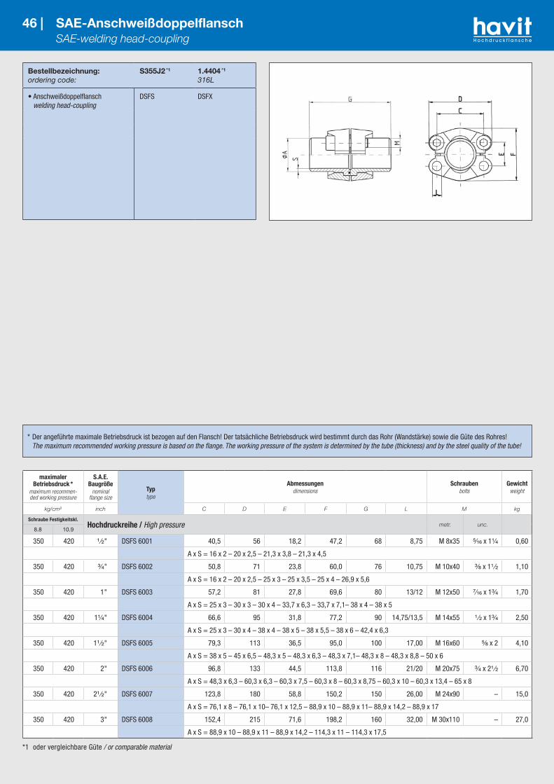
*1 oder vergleichbare Güte / or comparable material
Bestellbezeichnung:ordering code:
S355J2 *1
1.4404 *1
316L
• Anschweißdoppelflansch welding head-coupling
DSFS DSFX
46 | SAE-Anschweißdoppelflansch SAE-welding head-coupling
maximaler Betriebsdruck *
maximum recommen-ded working pressure
S.A.E. Baugröße
nominal flange size
Typtype
Abmessungendimensions
Schraubenbolts
Gewichtweight
kg/cm² inch C D E F G L M kg
Schraube Festigkeitskl.Hochdruckreihe / High pressure metr. unc.
8.8 10.9
350 420 ¹ ⁄₂" DSFS 6001 40,5 56 18,2 47,2 68 8,75 M 8x35 ⁵⁄₁₆ x 1¹⁄₄ 0,60
A x S = 16 x 2 – 20 x 2,5 – 21,3 x 3,8 – 21,3 x 4,5
350 420 ³⁄₄" DSFS 6002 50,8 71 23,8 60,0 76 10,75 M 10x40 ³⁄₈ x 1¹ ⁄₂ 1,10
A x S = 16 x 2 – 20 x 2,5 – 25 x 3 – 25 x 3,5 – 25 x 4 – 26,9 x 5,6
350 420 1" DSFS 6003 57,2 81 27,8 69,6 80 13/12 M 12x50 ⁷⁄₁₆ x 1³⁄₄ 1,70
A x S = 25 x 3 – 30 x 3 – 30 x 4 – 33,7 x 6,3 – 33,7 x 7,1– 38 x 4 – 38 x 5
350 420 1¹⁄₄" DSFS 6004 66,6 95 31,8 77,2 90 14,75/13,5 M 14x55 ¹ ⁄₂ x 1³⁄₄ 2,50
A x S = 25 x 3 – 30 x 4 – 38 x 4 – 38 x 5 – 38 x 5,5 – 38 x 6 – 42,4 x 6,3
350 420 1¹ ⁄₂" DSFS 6005 79,3 113 36,5 95,0 100 17,00 M 16x60 ⁵⁄₈ x 2 4,10
A x S = 38 x 5 – 45 x 6,5 – 48,3 x 5 – 48,3 x 6,3 – 48,3 x 7,1– 48,3 x 8 – 48,3 x 8,8 – 50 x 6
350 420 2" DSFS 6006 96,8 133 44,5 113,8 116 21/20 M 20x75 ³⁄₄ x 2¹ ⁄₂ 6,70
A x S = 48,3 x 6,3 – 60,3 x 6,3 – 60,3 x 7,5 – 60,3 x 8 – 60,3 x 8,75 – 60,3 x 10 – 60,3 x 13,4 – 65 x 8
350 420 2¹ ⁄₂" DSFS 6007 123,8 180 58,8 150,2 150 26,00 M 24x90 – 15,0
A x S = 76,1 x 8 – 76,1 x 10– 76,1 x 12,5 – 88,9 x 10 – 88,9 x 11– 88,9 x 14,2 – 88,9 x 17
350 420 3" DSFS 6008 152,4 215 71,6 198,2 160 32,00 M 30x110 – 27,0
A x S = 88,9 x 10 – 88,9 x 11 – 88,9 x 14,2 – 114,3 x 11 – 114,3 x 17,5
* Der angeführte maximale Betriebsdruck ist bezogen auf den Flansch! Der tatsächliche Betriebsdruck wird bestimmt durch das Rohr (Wandstärke) sowie die Güte des Rohres! The maximum recommended working pressure is based on the flange. The working pressure of the system is determined by the tube (thickness) and by the steel quality of the tube!

*1 oder vergleichbare Güte / or comparable material
Bestellbezeichnung:ordering code:
S355J2 *1
1.4404 *1
316L
• Flansch mit metrischen Schraubensatz und O-Ring flange with metric bolts and o-ring
DFS-…STM DFX-…STM
• Flansch mit UNC-Schraubensatz und O-Ring flange with UNC bolts and o-ring
DFS-…STU DFX-…STU
47 | SAE-Anschweiß-Flanschverbinder SAE-weld-on flange-coupling
maximaler Betriebsdruck *
maximum recommen-ded working pressure
S.A.E. Baugröße
nominal flange size
Typtype
Abmessungendimensions
Schraubenbolts
Gewichtweight
kg/cm² inch A B C D E F G H M kg
Schraube Festigkeitskl.Standarddruckreihe / Standard pressure metr. unc.
8.8 10.9
350 350 ¹ ⁄₂" DFS 080 ST 21,5 13,0 38,1 54 17,5 46 72 32 M 8x30 ⁵⁄₁₆ x 1¹⁄₄ 0,56
350 350 ¹ ⁄₂" DFS 080 ST-038 17,5 13,0 38,1 54 17,5 46 72 32 M 8x30 ⁵⁄₁₆ x 1¹⁄₄ 0,50
350 350 ³⁄₄" DFS 100 ST 28,0 19,0 47,6 65 22,3 50 72 36 M 10x40 ³⁄₈ x 1¹ ⁄₂ 0,78
250 320 1" DFS 102 ST 34,0 25,0 52,4 70 26,2 55 76 36 M 10x40 ³⁄₈ x 1¹ ⁄₂ 0,92
200 280 1¹⁄₄" DFS 104 ST 42,8 32,0 58,7 79 30,2 68 82 42 M 10x45 ⁷⁄₁₆ x 1¹ ⁄₂ 1,32
200 210 1¹ ⁄₂" DFS 106 ST 48,6 38,0 69,9 93 35,7 78 88 50 M 12x50 ¹ ⁄₂ x 1³⁄₄ 2,10
160 210 2" DFS 108 ST 61,0 51,0 77,8 102 42,9 90 90 50 M 12x50 ¹ ⁄₂ x 1³⁄₄ 2,38
100 175 2¹ ⁄₂" DFS 110 ST 77,0 63,0 88,9 114 50,8 105 100 50 M 12x50 ¹ ⁄₂ x 1³⁄₄ 2,80
100 160 3" DFS 112 ST 92,0 73,0 106,4 134 61,9 124 100 54 M 16x55 ⁵⁄₈ x 2 4,30
35 35 3¹ ⁄₂" DFS 114 ST 103,0 89,0 120,7 152 69,9 136 96 54 M 16x55 ⁵⁄₈ x 2 4,80
35 35 4" DFS 116 ST 115,5 99,0 130,2 162 77,8 146 96 54 M 16x55 ⁵⁄₈ x 2 5,70
35 35 5" DFS 118 ST 140,2 120,0 152,4 184 92,1 180 100 56 M 16x60 ⁵⁄₈ x 2 10,00Schraube Festigkeitskl.
Hochdruckreihe / High pressure metr. unc.8.8 10.9
350 420 ¹ ⁄₂" DFS 401 ST-012 21,5 13,0 40,5 54 18,2 46 72 32 M 8x30 ⁵⁄₁₆ x 1¹⁄₄ 0,58
350 420 ¹ ⁄₂" DFS 401 ST-038 17,5 13,0 40,5 54 18,2 46 72 32 M 8x30 ⁵⁄₁₆ x 1¹⁄₄ 0,52
350 420 ³⁄₄" DFS 402 ST 28,0 19,0 50,8 71 23,8 55 70 42 M 10x45 ³⁄₈ x 1¹ ⁄₂ 1,00
350 420 1" DFS 403 ST 34,0 25,0 57,2 79 27,8 68 82 42 M 12x45 ⁷⁄₁₆ x 1³⁄₄ 1,52
350 375 1¹⁄₄" DFS 404 ST 42,8 32,0 66,6 95 31,8 78 88 50 M 14x50 ¹ ⁄₂ x 1³⁄₄ 2,40
350 420 1¹⁄₄" DFS 404 ST 160 42,8 29,0 66,6 95 31,8 78 88 50 M 14x50 ¹ ⁄₂ x 1³⁄₄ 2,80
250 250 1¹ ⁄₂" DFS 405 ST 48,6 38,0 79,3 114 36,5 94 110 60 M 16x60 ⁵⁄₈ x 2 3,30
350 420 1¹ ⁄₂" DFS 405 ST 160 48,6 34,0 79,3 114 36,5 94 110 60 M 16x60 ⁵⁄₈ x 2 4,00
250 250 2" DFS 406 ST 61,0 51,0 96,8 134 44,5 114 130 74 M 20x75 ³⁄₄ x 2¹ ⁄₂ 4,90
350 420 2" DFS 406 ST 160 61,0 43,0 96,8 134 44,5 114 130 74 M 20x75 ³⁄₄ x 2¹ ⁄₂ 5,50
350 420 2¹ ⁄₂" DFS 407 ST 76 76,1 51,0 123,8 180 58,8 152 160 90 M 24x90 – 12,80
350 420 2¹ ⁄₂" DFS 407 ST 88 88,9 60,5 123,8 180 58,8 152 160 90 M 24x90 – 16,60
* Der angeführte maximale Betriebsdruck ist bezogen auf den Flansch! Der tatsächliche Betriebsdruck wird bestimmt durch das Rohr (Wandstärke) sowie die Güte des Rohres! The maximum recommended working pressure is based on the flange. The working pressure of the system is determined by the tube (thickness) and by the steel quality of the tube!

Bestellbezeichnung:ordering code:
S355J2 *1
• nur Adapter adaptor only
SWA-…
• incl. Flanschhälften, metrischem Schraubensatz und O-Ring including split flanges, metric bolts and o-ring
SWA-…M
• incl. Flanschhälften, UNC-Schraubensatz und O-Ring including split flanges, UNC bolts and o-ring (nut and cutting ring)
SWA-…U
48 | SAE-Einschweiß-Adapter SAE-socket weld adapter
*1 oder vergleichbare Güte / or comparable material*2 wahlweise 10,75, 12,00 oder 12,75 / choice of 10.75, 12.00 or 12.75 *3 wahlweise M 10x30 oder M 12x35 / choice of M 10x30 or M 12x35
*4 wahlweise 12,0 oder 13,0 / choice of 12.0 or 13.0 *5 wahlweise 13,5 oder 14,75 / choice of 13.5 or 14.75
maximaler Betriebsdruck
maximum recommen-ded working pressure
S.A.E. Baugröße
nominal flange size
Typtype
Abmessungendimensions
Schraubenbolts
Gewichtweight
kg/cm² inch A A1 B C D E F G I L M kg
Schraube Festigkeitskl.Standarddruckreihe / Standard pressure metr. unc.
8.8 10.9
350 350 ¹ ⁄₂" SWA-3001-20 20,30 30,2 13 38,1 54 17,5 46 50 15,0 8,75 M 8x25 ⁵⁄₁₆ x 1¹⁄₄ –
350 350 ¹ ⁄₂" SWA-3001-21,3 21,60 30,2 13 38,1 54 17,5 46 50 15,0 8,75 M 8x25 ⁵⁄₁₆ x 1¹⁄₄ 0,3
350 350 ³⁄₄" SWA-3002-25 25,30 38,1 19 47,6 65 22,3 52 60 14,8 10,75 M 10x30 ³⁄₈ x 1¹⁄₄ 0,6
350 350 ³⁄₄" SWA-3002-26,7 26,97 38,1 19 47,6 65 22,3 52 60 14,8 10,75 M 10x30 ³⁄₈ x 1¹⁄₄ 0,6
250 320 1" SWA-3003-30 30,30 44,5 24 52,4 70 26,2 59 60 15,6 10,75 M 10x30 ³⁄₈ x 1¹⁄₄ 0,9
250 320 1" SWA-3003-33,4 33,73 44,5 24 52,4 70 26,2 59 60 15,6 10,75 M 10x30 ³⁄₈ x 1¹⁄₄ 0,9
200 280 1¹⁄₄" SWA-3004-38 38,30 50,8 32 58,7 79 30,2 73 66 16,7 *2 *3 ⁷⁄₁₆ x 1¹ ⁄₂ 1,2
200 280 1¹⁄₄" SWA-3004-42,2 42,47 50,8 32 58,7 79 30,2 73 66 16,7 *2 *3 ⁷⁄₁₆ x 1¹ ⁄₂ 1,2
200 210 1¹ ⁄₂" SWA-3005-48,3 48,82 60,3 38 69,9 94 35,7 83 73 19,2 13,50 M 12x35 ¹ ⁄₂ x 1¹ ⁄₂ 1,5
200 210 1¹ ⁄₂" SWA-3005-50 50,30 60,3 38 69,9 94 35,7 83 73 19,2 13,50 M 12x35 ¹ ⁄₂ x 1¹ ⁄₂ 1,5
160 210 2" SWA-3006-60,3 61,11 71,4 51 77,8 102 42,9 97 76 22,2 13,50 M 12x35 ¹ ⁄₂ x 1¹ ⁄₂ –
100 175 2¹ ⁄₂" SWA-3007-76,1 76,40 84,1 62 88,9 114 50,8 109 100 25,0 13,50 M 12x40 ¹ ⁄₂ x 1¹ ⁄₂ –
100 160 3" SWA-3008-88,9 90,40 101,6 73 106,4 135 61,9 131 125 28,0 17,00 M 16x50 ⁵⁄₈ x 2 –Schraube Festigkeitskl.
Hochdruckreihe / High pressure metr. unc.8.8 10.9
350 420 ¹ ⁄₂" SWA-6001-20 20,30 31,8 12 40,5 56 18,2 48 65 14,0 8,75 M 8x30 ⁵⁄₁₆ x 1¹⁄₄ 0,5
350 420 ¹ ⁄₂" SWA-6001-21,3 21,60 31,8 12 40,5 56 18,2 48 65 14,0 8,75 M 8x30 ⁵⁄₁₆ x 1¹⁄₄ 0,5
350 420 ³⁄₄" SWA-6002-25 25,30 41,3 17 50,8 71 23,8 60 70 15,5 10,75 M 10x35 ³⁄₈ x 1¹ ⁄₂ 1,2
350 420 ³⁄₄" SWA-6002-26,7 26,97 41,3 17 50,8 71 23,8 60 70 15,5 10,75 M 10x35 ³⁄₈ x 1¹ ⁄₂ 1,2
350 420 1" SWA-6003-30 30,30 47,6 22 57,2 81 27,8 70 78 16,3 *4 M 12x45 ⁷⁄₁₆ x 1³⁄₄ 1,5
350 420 1" SWA-6003-33,4 33,73 47,6 25 57,2 81 27,8 70 78 16,3 *4 M 12x45 ⁷⁄₁₆ x 1³⁄₄ 1,5
350 420 1¹⁄₄" SWA-6004-38 38,30 54,0 28 66,6 95 31,8 78 84 17,5 *5 M 14x50 ¹ ⁄₂ x 1³⁄₄ 2,0
350 420 1¹⁄₄" SWA-6004-42,2 42,47 54,0 28 66,6 95 31,8 78 84 17,5 *5 M 14x50 ¹ ⁄₂ x 1³⁄₄ 2,0
350 420 1¹ ⁄₂" SWA-6005-50 50,30 63,5 35 79,3 113 36,5 95 100 19,2 17,00 M 16x55 ⁵⁄₈ x 2 3,0
350 420 1¹ ⁄₂" SWA-6005-48,3 48,82 63,5 35 79,3 113 36,5 95 100 19,2 17,00 M 16x55 ⁵⁄₈ x 2 3,0
350 420 2" SWA-6006-60,3 61,11 79,4 48 96,8 133 44,5 114 103 22,2 21,00 M 20x70 ³⁄₄ x 2¹ ⁄₂ –
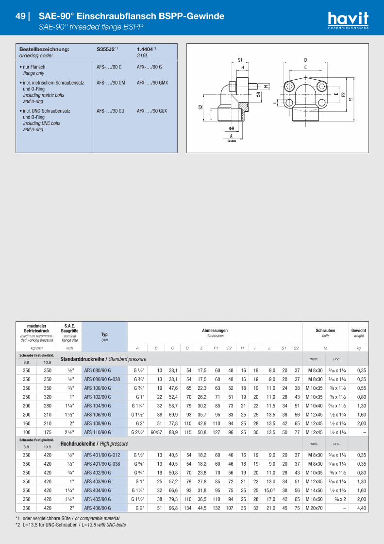
*1 oder vergleichbare Güte / or comparable material*2 L=13,5 für UNC-Schrauben / L=13.5 with UNC-bolts
Bestellbezeichnung:ordering code:
S355J2 *1
1.4404 *1
316L
• nur Flansch flange only
AFS-…/90 G AFX-…/90 G
• incl. metrischem Schraubensatz und O-Ring including metric bolts and o-ring
AFS-…/90 GM AFX-…/90 GMX
• incl. UNC-Schraubensatz und O-Ring including UNC bolts and o-ring
AFS-…/90 GU AFX-…/90 GUX
49 | SAE-90° Einschraubflansch BSPP-Gewinde SAE-90° threaded flange BSPP
maximaler Betriebsdruck
maximum recommen-ded working pressure
S.A.E. Baugröße
nominal flange size
Typtype
Abmessungendimensions
Schraubenbolts
Gewichtweight
kg/cm² inch A B C D E F1 F2 H I L S1 S2 M kg
Schraube Festigkeitskl.Standarddruckreihe / Standard pressure metr. unc.
8.8 10.9
350 350 ¹ ⁄₂" AFS 080/90 G G ¹ ⁄₂" 13 38,1 54 17,5 60 48 16 19 9,0 20 37 M 8x30 ⁵⁄₁₆ x 1¹⁄₄ 0,35
350 350 ¹ ⁄₂" AFS 080/90 G-038 G ³⁄₈" 13 38,1 54 17,5 60 48 16 19 9,0 20 37 M 8x30 ⁵⁄₁₆ x 1¹⁄₄ 0,35
350 350 ³⁄₄" AFS 100/90 G G ³⁄₄" 19 47,6 65 22,3 63 52 18 19 11,0 24 38 M 10x35 ³⁄₈ x 1¹ ⁄₂ 0,55
250 320 1" AFS 102/90 G G 1" 22 52,4 70 26,2 71 51 19 20 11,0 28 43 M 10x35 ³⁄₈ x 1¹ ⁄₂ 0,80
200 280 1¹⁄₄" AFS 104/90 G G 1¹⁄₄" 32 58,7 79 30,2 85 73 21 22 11,5 34 51 M 10x40 ⁷⁄₁₆ x 1¹ ⁄₂ 1,30
200 210 1¹ ⁄₂" AFS 106/90 G G 1¹ ⁄₂" 38 69,9 93 35,7 95 83 25 25 13,5 38 56 M 12x45 ¹ ⁄₂ x 1³⁄₄ 1,60
160 210 2" AFS 108/90 G G 2" 51 77,8 110 42,9 110 94 25 28 13,5 42 65 M 12x45 ¹ ⁄₂ x 1³⁄₄ 2,00
100 175 2¹ ⁄₂" AFS 110/90 G G 2¹ ⁄₂" 60/57 88,9 115 50,8 127 96 25 30 13,5 50 77 M 12x45 ¹ ⁄₂ x 1³⁄₄ –Schraube Festigkeitskl.
Hochdruckreihe / High pressure metr. unc.8.8 10.9
350 420 ¹ ⁄₂" AFS 401/90 G-012 G ¹ ⁄₂" 13 40,5 54 18,2 60 46 16 19 9,0 20 37 M 8x30 ⁵⁄₁₆ x 1¹⁄₄ 0,35
350 420 ¹ ⁄₂" AFS 401/90 G-038 G ³⁄₈" 13 40,5 54 18,2 60 46 16 19 9,0 20 37 M 8x30 ⁵⁄₁₆ x 1¹⁄₄ 0,35
350 420 ³⁄₄" AFS 402/90 G G ³⁄₄" 19 50,8 70 23,8 70 56 19 20 11,0 28 43 M 10x35 ³⁄₈ x 1¹ ⁄₂ 0,80
350 420 1" AFS 403/90 G G 1" 25 57,2 79 27,8 85 72 21 22 13,0 34 51 M 12x45 ⁷⁄₁₆ x 1³⁄₄ 1,30
350 420 1¹⁄₄" AFS 404/90 G G 1¹⁄₄" 32 66,6 93 31,8 95 75 25 25 15,0*2 38 56 M 14x50 ¹ ⁄₂ x 1³⁄₄ 1,60
350 420 1¹ ⁄₂" AFS 405/90 G G 1¹ ⁄₂" 38 79,3 110 36,5 110 94 25 28 17,0 42 65 M 16x50 ⁵⁄₈ x 2 2,00
350 420 2" AFS 406/90 G G 2" 51 96,8 134 44,5 132 107 35 33 21,0 45 75 M 20x70 – 4,40
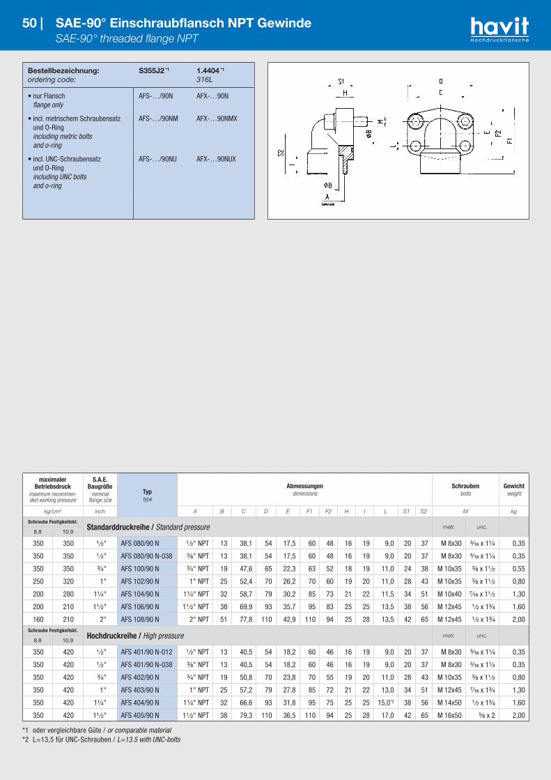
*1 oder vergleichbare Güte / or comparable material*2 L=13,5 für UNC-Schrauben / L=13.5 with UNC-bolts
Bestellbezeichnung:ordering code:
S355J2 *1
1.4404 *1
316L
• nur Flansch flange only
AFS-…/90N AFX-…90N
• incl. metrischem Schraubensatz und O-Ring including metric bolts and o-ring
AFS-…/90NM AFX-…90NMX
• incl. UNC-Schraubensatz und O-Ring including UNC bolts and o-ring
AFS-…/90NU AFX-…90NUX
50 | SAE-90° Einschraubflansch NPT Gewinde SAE-90° threaded flange NPT
maximaler Betriebsdruck
maximum recommen-ded working pressure
S.A.E. Baugröße
nominal flange size
Typtype
Abmessungendimensions
Schraubenbolts
Gewichtweight
kg/cm² inch A B C D E F1 F2 H I L S1 S2 M kg
Schraube Festigkeitskl.Standarddruckreihe / Standard pressure metr. unc.
8.8 10.9
350 350 ¹ ⁄₂" AFS 080/90 N ¹ ⁄₂" NPT 13 38,1 54 17,5 60 48 16 19 9,0 20 37 M 8x30 ⁵⁄₁₆ x 1¹⁄₄ 0,35
350 350 ¹ ⁄₂" AFS 080/90 N-038 ³⁄₈" NPT 13 38,1 54 17,5 60 48 16 19 9,0 20 37 M 8x30 ⁵⁄₁₆ x 1¹⁄₄ 0,35
350 350 ³⁄₄" AFS 100/90 N ³⁄₄" NPT 19 47,6 65 22,3 63 52 18 19 11,0 24 38 M 10x35 ³⁄₈ x 1¹ ⁄₂ 0,55
250 320 1" AFS 102/90 N 1" NPT 25 52,4 70 26,2 70 60 19 20 11,0 28 43 M 10x35 ³⁄₈ x 1¹ ⁄₂ 0,80
200 280 1¹⁄₄" AFS 104/90 N 1¹⁄₄" NPT 32 58,7 79 30,2 85 73 21 22 11,5 34 51 M 10x40 ⁷⁄₁₆ x 1¹ ⁄₂ 1,30
200 210 1¹ ⁄₂" AFS 106/90 N 1¹ ⁄₂" NPT 38 69,9 93 35,7 95 83 25 25 13,5 38 56 M 12x45 ¹ ⁄₂ x 1³⁄₄ 1,60
160 210 2" AFS 108/90 N 2" NPT 51 77,8 110 42,9 110 94 25 28 13,5 42 65 M 12x45 ¹ ⁄₂ x 1³⁄₄ 2,00Schraube Festigkeitskl.
Hochdruckreihe / High pressure metr. unc.8.8 10.9
350 420 ¹ ⁄₂" AFS 401/90 N-012 ¹ ⁄₂" NPT 13 40,5 54 18,2 60 46 16 19 9,0 20 37 M 8x30 ⁵⁄₁₆ x 1¹⁄₄ 0,35
350 420 ¹ ⁄₂" AFS 401/90 N-038 ³⁄₈" NPT 13 40,5 54 18,2 60 46 16 19 9,0 20 37 M 8x30 ⁵⁄₁₆ x 1¹⁄₄ 0,35
350 420 ³⁄₄" AFS 402/90 N ³⁄₄" NPT 19 50,8 70 23,8 70 55 19 20 11,0 28 43 M 10x35 ³⁄₈ x 1¹ ⁄₂ 0,80
350 420 1" AFS 403/90 N 1" NPT 25 57,2 79 27,8 85 72 21 22 13,0 34 51 M 12x45 ⁷⁄₁₆ x 1³⁄₄ 1,30
350 420 1¹⁄₄" AFS 404/90 N 1¹⁄₄" NPT 32 66,6 93 31,8 95 75 25 25 15,0*2 38 56 M 14x50 ¹ ⁄₂ x 1³⁄₄ 1,60
350 420 1¹ ⁄₂" AFS 405/90 N 1¹ ⁄₂" NPT 38 79,3 110 36,5 110 94 25 28 17,0 42 65 M 16x50 ⁵⁄₈ x 2 2,00
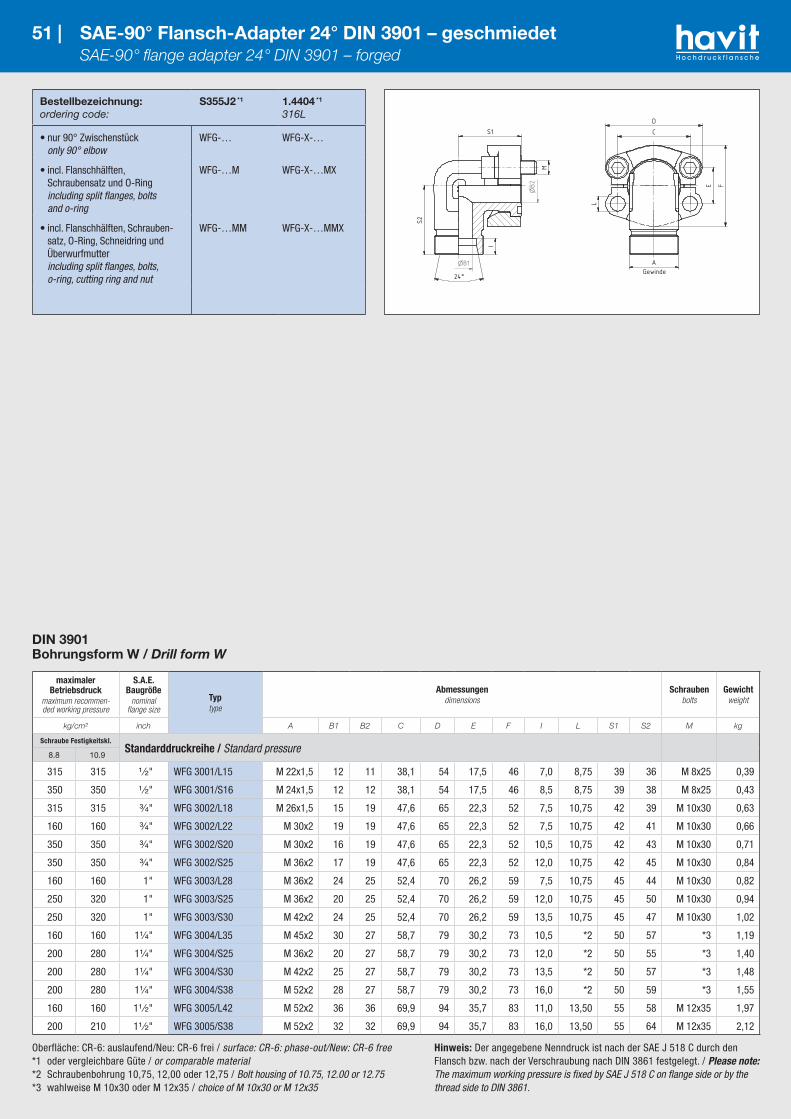
Oberfläche: CR-6: auslaufend/Neu: CR-6 frei / surface: CR-6: phase-out/New: CR-6 free*1 oder vergleichbare Güte / or comparable material *2 Schraubenbohrung 10,75, 12,00 oder 12,75 / Bolt housing of 10.75, 12.00 or 12.75 *3 wahlweise M 10x30 oder M 12x35 / choice of M 10x30 or M 12x35
Bestellbezeichnung:ordering code:
S355J2 *1
1.4404 *1
316L
• nur 90° Zwischenstück only 90° elbow
WFG-… WFG-X-…
• incl. Flanschhälften, Schraubensatz und O-Ring including split flanges, bolts and o-ring
WFG-…M WFG-X-…MX
• incl. Flanschhälften, Schrauben-satz, O-Ring, Schneidring und Überwurfmutter including split flanges, bolts, o-ring, cutting ring and nut
WFG-…MM WFG-X-…MMX
51 | SAE-90° Flansch-Adapter 24° DIN 3901 – geschmiedet SAE-90° flange adapter 24° DIN 3901 – forged
maximaler Betriebsdruck
maximum recommen-ded working pressure
S.A.E. Baugröße
nominal flange size
Typtype
Abmessungendimensions
Schraubenbolts
Gewichtweight
kg/cm² inch A B1 B2 C D E F I L S1 S2 M kg
Schraube Festigkeitskl.Standarddruckreihe / Standard pressure
8.8 10.9
315 315 ¹ ⁄₂" WFG 3001/L15 M 22x1,5 12 11 38,1 54 17,5 46 7,0 8,75 39 36 M 8x25 0,39
350 350 ¹ ⁄₂" WFG 3001/S16 M 24x1,5 12 12 38,1 54 17,5 46 8,5 8,75 39 38 M 8x25 0,43
315 315 ³⁄₄" WFG 3002/L18 M 26x1,5 15 19 47,6 65 22,3 52 7,5 10,75 42 39 M 10x30 0,63
160 160 ³⁄₄" WFG 3002/L22 M 30x2 19 19 47,6 65 22,3 52 7,5 10,75 42 41 M 10x30 0,66
350 350 ³⁄₄" WFG 3002/S20 M 30x2 16 19 47,6 65 22,3 52 10,5 10,75 42 43 M 10x30 0,71
350 350 ³⁄₄" WFG 3002/S25 M 36x2 17 19 47,6 65 22,3 52 12,0 10,75 42 45 M 10x30 0,84
160 160 1" WFG 3003/L28 M 36x2 24 25 52,4 70 26,2 59 7,5 10,75 45 44 M 10x30 0,82
250 320 1" WFG 3003/S25 M 36x2 20 25 52,4 70 26,2 59 12,0 10,75 45 50 M 10x30 0,94
250 320 1" WFG 3003/S30 M 42x2 24 25 52,4 70 26,2 59 13,5 10,75 45 47 M 10x30 1,02
160 160 1¹⁄₄" WFG 3004/L35 M 45x2 30 27 58,7 79 30,2 73 10,5 *2 50 57 *3 1,19
200 280 1¹⁄₄" WFG 3004/S25 M 36x2 20 27 58,7 79 30,2 73 12,0 *2 50 55 *3 1,40
200 280 1¹⁄₄" WFG 3004/S30 M 42x2 25 27 58,7 79 30,2 73 13,5 *2 50 57 *3 1,48
200 280 1¹⁄₄" WFG 3004/S38 M 52x2 28 27 58,7 79 30,2 73 16,0 *2 50 59 *3 1,55
160 160 1¹ ⁄₂" WFG 3005/L42 M 52x2 36 36 69,9 94 35,7 83 11,0 13,50 55 58 M 12x35 1,97
200 210 1¹ ⁄₂" WFG 3005/S38 M 52x2 32 32 69,9 94 35,7 83 16,0 13,50 55 64 M 12x35 2,12
DIN 3901 Bohrungsform W / Drill form W
Hinweis: Der angegebene Nenndruck ist nach der SAE J 518 C durch den Flansch bzw. nach der Verschraubung nach DIN 3861 festgelegt. / Please note: The maximum working pressure is fixed by SAE J 518 C on flange side or by the thread side to DIN 3861.

Bestellbezeichnung:ordering code:
S355J2 *1
1.4404 *1
316L
• nur 90° Zwischenstück only 90° elbow
WFG-… WFGX-…
• incl. Flanschhälften, Schraubensatz und O-Ring including split flanges, bolts and o-ring
WFG-…M WFG-X-…MX
• incl. Flanschhälften, Schraubensatz, O-Ring, Schneidring und Überwurfmutter including split flanges, bolts, o-ring, cutting ring and nut
WFG-…MM WFG-X-…MMX
Oberfläche: CR-6: auslaufend/Neu: CR-6 frei / surface: CR-6: phase-out/New: CR-6 free*1 oder vergleichbare Güte / or comparable material
52 | SAE-90° Flansch-Adapter 24° DIN 3901 – geschmiedet SAE-90° flange adapter 24° DIN 3901 – forged
maximaler Betriebsdruck
maximum recommen-ded working pressure
S.A.E. Baugröße
nominal flange size
Typtype
Abmessungendimensions
Schraubenbolts
Gewichtweight
kg/cm² inch A B1 B2 C D E F I L S1 S2 M kg
Schraube Festigkeitskl.Hochdruckreihe / High pressure
8.8 10.9
350 420 ¹ ⁄₂" WFG 6001/S16 M 24x1,5 12 12 40,5 56 18,2 48 8,5 8,75 39 38 M 8x30 0,69
350 420 ³⁄₄" WFG 6002/S16 M 24x1,5 12 17 50,8 71 23,8 60 8,5 10,75 48 45 M 10x35 0,92
350 420 ³⁄₄" WFG 6002/S20 M 30x2 16 17 50,8 71 23,8 60 10,5 10,75 48 46 M 10x35 0,96
350 420 ³⁄₄" WFG 6002/S25 M 36x2 17 17 50,8 71 23,8 60 12,0 10,75 48 48 M 10x35 1,09
350 420 1" WFG 6003/S25 M 36x2 20 24 57,2 81 27,8 70 12,0 13,00 60 53 M 12x45 1,60
350 420 1" WFG 6003/S30 M 42x2 24 24 57,2 81 27,8 70 13,5 13,00 60 55 M 12x45 1,70
350 420 1¹⁄₄" WFG 6004/S30 M 42x2 25 31 66,6 95 31,8 78 13,5 14,75 68 58 M 14x50 2,22
350 350 1¹⁄₄" WFG 6004/S38 M 52x2 28 31 66,6 95 31,8 78 16,0 14,75 68 63 M 14x50 2,32
350 350 1¹ ⁄₂" WFG 6005/S30 M 42x2 25 36 79,3 113 36,5 95 13,5 17,00 76 72 M 16x55 3,30
350 350 1¹ ⁄₂" WFG 6005/S38 M 52x2 30 36 79,3 113 36,5 95 16,0 17,00 76 72 M 16x55 3,55
DIN 3901 Bohrungsform W / Drill form W
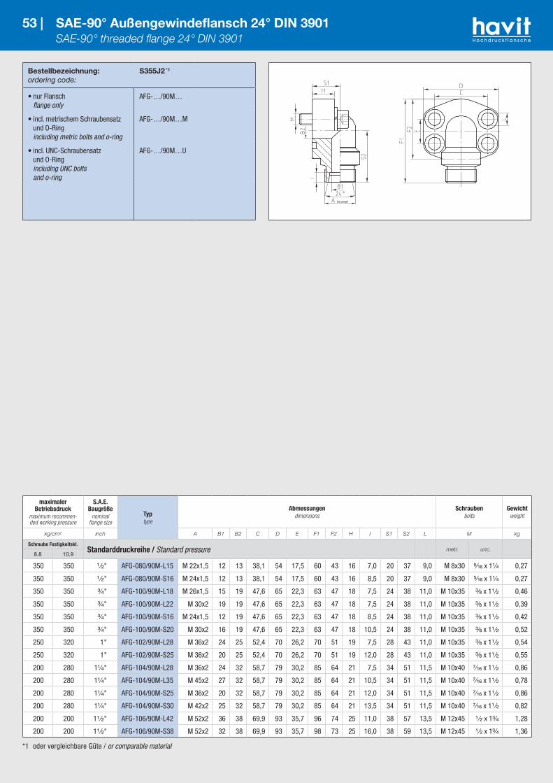
*1 oder vergleichbare Güte / or comparable material
Bestellbezeichnung:ordering code:
S355J2 *1
• nur Flansch flange only
AFG-…/90M…
• incl. metrischem Schraubensatz und O-Ring including metric bolts and o-ring
AFG-…/90M…M
• incl. UNC-Schraubensatz und O-Ring including UNC bolts and o-ring
AFG-…/90M…U
53 | SAE-90° Außengewindeflansch 24° DIN 3901 SAE-90° threaded flange 24° DIN 3901
maximaler Betriebsdruck
maximum recommen-ded working pressure
S.A.E. Baugröße
nominal flange size
Typtype
Abmessungendimensions
Schraubenbolts
Gewichtweight
kg/cm² inch A B1 B2 C D E F1 F2 H I S1 S2 L M kg
Schraube Festigkeitskl.Standarddruckreihe / Standard pressure metr. unc.
8.8 10.9
350 350 ¹ ⁄₂" AFG-080/90M-L15 M 22x1,5 12 13 38,1 54 17,5 60 43 16 7,0 20 37 9,0 M 8x30 ⁵⁄₁₆ x 1¹⁄₄ 0,27
350 350 ¹ ⁄₂" AFG-080/90M-S16 M 24x1,5 12 13 38,1 54 17,5 60 43 16 8,5 20 37 9,0 M 8x30 ⁵⁄₁₆ x 1¹⁄₄ 0,27
350 350 ³⁄₄" AFG-100/90M-L18 M 26x1,5 15 19 47,6 65 22,3 63 47 18 7,5 24 38 11,0 M 10x35 ³⁄₈ x 1¹ ⁄₂ 0,46
350 350 ³⁄₄" AFG-100/90M-L22 M 30x2 19 19 47,6 65 22,3 63 47 18 7,5 24 38 11,0 M 10x35 ³⁄₈ x 1¹ ⁄₂ 0,39
350 350 ³⁄₄" AFG-100/90M-S16 M 24x1,5 12 19 47,6 65 22,3 63 47 18 8,5 24 38 11,0 M 10x35 ³⁄₈ x 1¹ ⁄₂ 0,42
350 350 ³⁄₄" AFG-100/90M-S20 M 30x2 16 19 47,6 65 22,3 63 47 18 10,5 24 38 11,0 M 10x35 ³⁄₈ x 1¹ ⁄₂ 0,52
250 320 1" AFG-102/90M-L28 M 36x2 24 25 52,4 70 26,2 70 51 19 7,5 28 43 11,0 M 10x35 ³⁄₈ x 1¹ ⁄₂ 0,54
250 320 1" AFG-102/90M-S25 M 36x2 20 25 52,4 70 26,2 70 51 19 12,0 28 43 11,0 M 10x35 ³⁄₈ x 1¹ ⁄₂ 0,55
200 280 1¹⁄₄" AFG-104/90M-L28 M 36x2 24 32 58,7 79 30,2 85 64 21 7,5 34 51 11,5 M 10x40 ⁷⁄₁₆ x 1¹ ⁄₂ 0,86
200 280 1¹⁄₄" AFG-104/90M-L35 M 45x2 27 32 58,7 79 30,2 85 64 21 10,5 34 51 11,5 M 10x40 ⁷⁄₁₆ x 1¹ ⁄₂ 0,78
200 280 1¹⁄₄" AFG-104/90M-S25 M 36x2 20 32 58,7 79 30,2 85 64 21 12,0 34 51 11,5 M 10x40 ⁷⁄₁₆ x 1¹ ⁄₂ 0,86
200 280 1¹⁄₄" AFG-104/90M-S30 M 42x2 25 32 58,7 79 30,2 85 64 21 13,5 34 51 11,5 M 10x40 ⁷⁄₁₆ x 1¹ ⁄₂ 0,82
200 200 1¹ ⁄₂" AFG-106/90M-L42 M 52x2 36 38 69,9 93 35,7 96 74 25 11,0 38 57 13,5 M 12x45 ¹ ⁄₂ x 1³⁄₄ 1,28
200 200 1¹ ⁄₂" AFG-106/90M-S38 M 52x2 32 38 69,9 93 35,7 98 73 25 16,0 38 59 13,5 M 12x45 ¹ ⁄₂ x 1³⁄₄ 1,36
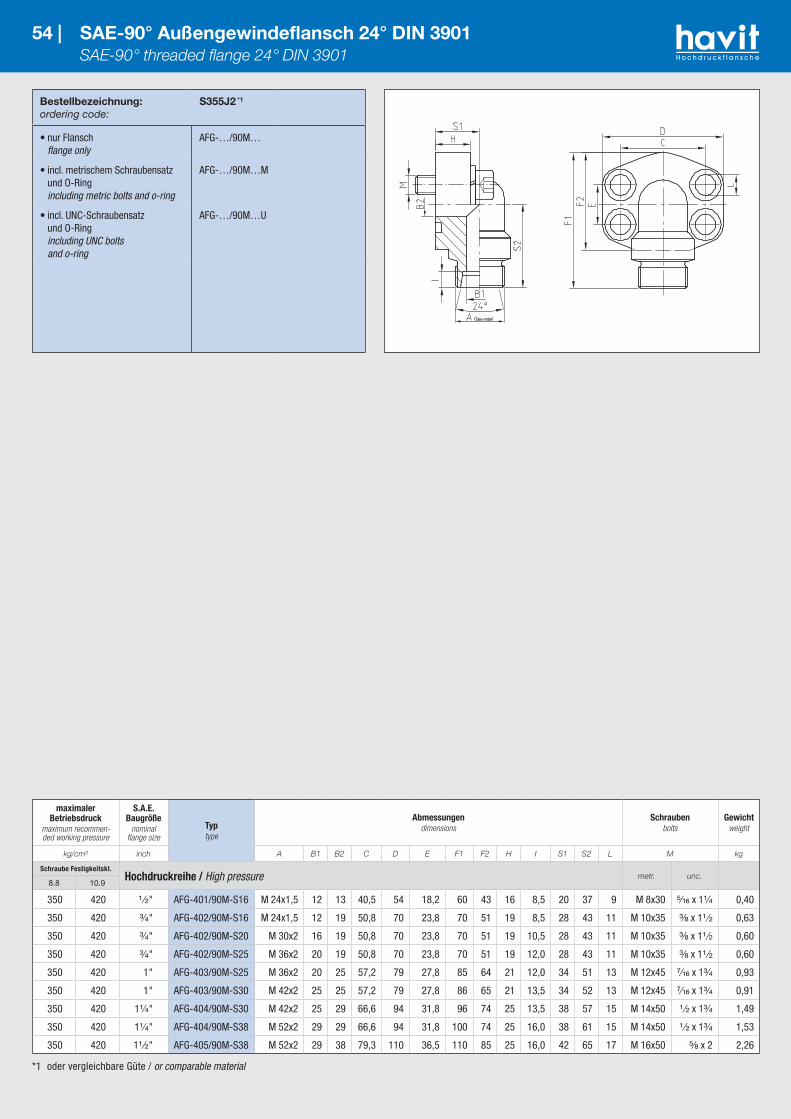
*1 oder vergleichbare Güte / or comparable material
Bestellbezeichnung:ordering code:
S355J2 *1
• nur Flansch flange only
AFG-…/90M…
• incl. metrischem Schraubensatz und O-Ring including metric bolts and o-ring
AFG-…/90M…M
• incl. UNC-Schraubensatz und O-Ring including UNC bolts and o-ring
AFG-…/90M…U
54 | SAE-90° Außengewindeflansch 24° DIN 3901 SAE-90° threaded flange 24° DIN 3901
maximaler Betriebsdruck
maximum recommen-ded working pressure
S.A.E. Baugröße
nominal flange size
Typtype
Abmessungendimensions
Schraubenbolts
Gewichtweight
kg/cm² inch A B1 B2 C D E F1 F2 H I S1 S2 L M kg
Schraube Festigkeitskl.Hochdruckreihe / High pressure metr. unc.
8.8 10.9
350 420 ¹ ⁄₂" AFG-401/90M-S16 M 24x1,5 12 13 40,5 54 18,2 60 43 16 8,5 20 37 9 M 8x30 ⁵⁄₁₆ x 1¹⁄₄ 0,40
350 420 ³⁄₄" AFG-402/90M-S16 M 24x1,5 12 19 50,8 70 23,8 70 51 19 8,5 28 43 11 M 10x35 ³⁄₈ x 1¹ ⁄₂ 0,63
350 420 ³⁄₄" AFG-402/90M-S20 M 30x2 16 19 50,8 70 23,8 70 51 19 10,5 28 43 11 M 10x35 ³⁄₈ x 1¹ ⁄₂ 0,60
350 420 ³⁄₄" AFG-402/90M-S25 M 36x2 20 19 50,8 70 23,8 70 51 19 12,0 28 43 11 M 10x35 ³⁄₈ x 1¹ ⁄₂ 0,60
350 420 1" AFG-403/90M-S25 M 36x2 20 25 57,2 79 27,8 85 64 21 12,0 34 51 13 M 12x45 ⁷⁄₁₆ x 1³⁄₄ 0,93
350 420 1" AFG-403/90M-S30 M 42x2 25 25 57,2 79 27,8 86 65 21 13,5 34 52 13 M 12x45 ⁷⁄₁₆ x 1³⁄₄ 0,91
350 420 1¹⁄₄" AFG-404/90M-S30 M 42x2 25 29 66,6 94 31,8 96 74 25 13,5 38 57 15 M 14x50 ¹ ⁄₂ x 1³⁄₄ 1,49
350 420 1¹⁄₄" AFG-404/90M-S38 M 52x2 29 29 66,6 94 31,8 100 74 25 16,0 38 61 15 M 14x50 ¹ ⁄₂ x 1³⁄₄ 1,53
350 420 1¹ ⁄₂" AFG-405/90M-S38 M 52x2 29 38 79,3 110 36,5 110 85 25 16,0 42 65 17 M 16x50 ⁵⁄₈ x 2 2,26
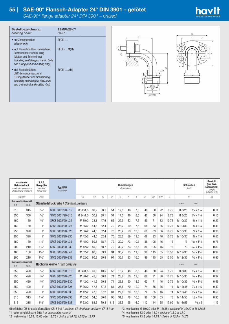
Oberfläche: CR-6: auslaufend/Neu: CR-6 frei / surface: CR-6: phase-out/New: CR-6 free*1 oder vergleichbare Güte / or comparable material*2 wahlweise 10,75, 12,00 oder 12,75 / choice of 10.75, 12.00 or 12.75
*3 wahlweise M 10x30 oder M 12x35 / choice of M 10x30 or M 12x35*4 wahlweise 12,0 oder 13,0 / choice of 12.0 or 13.0 *5 wahlweise 13,5 oder 14,75 / choice of 13.5 or 14.75
Bestellbezeichnung:ordering code:
9SMPb28K *1
ST37 *1
• nur Zwischenstück adapter only
SFCE-…
• incl. Flanschhälften, metrischem Schraubensatz und O-Ring (Mutter und Schneidring) including split flanges, metric bolts and o-ring (nut and cutting ring)
SFCE-…M(M)
• incl. Flanschhälften, UNC-Schraubensatz und O-Ring (Mutter und Schneidring) including split flanges, UNC bolts and o-ring (nut and cutting ring)
SFCE-…U(M)
55 | SAE-90° Flansch-Adapter 24° DIN 3901 – gelötet SAE-90° flange adapter 24° DIN 3901 – brazed
maximaler Betriebsdruck
maximum recommen-ded working pressure
S.A.E. Baugröße
nominal flange size
Typ/RADtype/RAD
Abmessungendimensions
Schraubenbolts
Gewicht (nur Zwi-
schenstück)weight
(adapter only)
kg/cm² inch A A1 C D E F I S1 S2 SW L M kg
Schraube Festigkeitskl.Standarddruckreihe / Standard pressure metr. unc.
8.8 10.9
315 315 ¹ ⁄₂" SFCE 3001/90-L15 M 22x1,5 30,2 38,1 54 17,5 46 7,0 40 50 22 8,75 M 8x25 ⁵⁄₁₆ x 1¹⁄₄ 0,14
350 350 ¹ ⁄₂" SFCE 3001/90-S16 M 24x1,5 30,2 38,1 54 17,5 46 8,5 40 50 24 8,75 M 8x25 ⁵⁄₁₆ x 1¹⁄₄ 0,15
160 160 ³⁄₄" SFCE 3002/90-L22 M 30x2 38,1 47,6 65 22,3 52 7,5 59 71 32 10,75 M 10x30 ³⁄₈ x 1¹⁄₄ 0,29
160 160 1" SFCE 3003/90-L28 M 36x2 44,5 52,4 70 26,2 59 7,5 68 83 36 10,75 M 10x30 ³⁄₈ x 1¹⁄₄ 0,43
250 320 1" SFCE 3003/90-S25 M 36x2 44,5 52,4 70 26,2 59 12,0 68 83 36 10,75 M 10x30 ³⁄₈ x 1¹⁄₄ 0,38
250 320 1" SFCE 3003/90-S30 M 42x2 44,5 52,4 70 26,2 59 13,5 68 83 46 10,75 M 10x30 ³⁄₈ x 1¹⁄₄ 0,55
160 160 1¹⁄₄" SFCE 3004/90-L35 M 45x2 50,8 58,7 79 30,2 73 10,5 86 105 46 *2 *3 ⁷⁄₁₆ x 1¹ ⁄₂ 0,76
200 210 1¹⁄₄" SFCE 3004/90-S30 M 42x2 50,8 58,7 79 30,2 73 13,5 86 105 46 *2 *3 ⁷⁄₁₆ x 1¹ ⁄₂ 0,83
160 160 1¹ ⁄₂" SFCE 3005/90-L42 M 52x2 60,3 69,9 94 35,7 83 11,0 98 115 55 13,50 M 12x35 ¹ ⁄₂ x 1¹ ⁄₂ 0,99
200 210 1¹ ⁄₂" SFCE 3005/90-S38 M 52x2 60,3 69,9 94 35,7 83 16,0 98 115 55 13,50 M 12x35 ¹ ⁄₂ x 1¹ ⁄₂ 0,95Schraube Festigkeitskl.
Hochdruckreihe / High pressure metr. unc.8.8 10.9
350 420 ¹ ⁄₂" SFCE 6001/90-S16 M 24x1,5 31,8 40,5 56 18,2 48 8,5 40 50 24 8,75 M 8x30 ⁵⁄₁₆ x 1¹⁄₄ 0,16
350 420 ³⁄₄" SFCE 6002/90-S25 M 36x2 41,3 50,8 71 23,8 60 12,0 62 71 36 10,75 M 10x35 ³⁄₈ x 1¹ ⁄₂ 0,37
350 420 ³⁄₄" SFCE 6002/90-S30 M 42x2 41,3 50,8 71 23,8 60 13,5 62 71 46 10,75 M 10x35 ³⁄₈ x 1¹ ⁄₂ 0,49
350 420 1" SFCE 6003/90-S25 M 36x2 47,6 57,2 81 27,8 70 12,0 74 85 36 *4 M 12x45 ⁷⁄₁₆ x 1³⁄₄ 0,43
350 420 1" SFCE 6003/90-S30 M 42x2 47,6 57,2 81 27,8 70 13,5 74 85 46 *4 M 12x45 ⁷⁄₁₆ x 1³⁄₄ 0,59
315 315 1¹⁄₄" SFCE 6004/90-S38 M 52x2 54,0 66,6 95 31,8 78 16,0 96 108 55 *5 M 14x50 ¹ ⁄₂ x 1³⁄₄ 0,95
315 315 1¹ ⁄₂" SFCE 6005/90-S38 M 52x2 63,5 79,3 113 36,5 95 16,0 112 114 55 17,00 M 16x55 ⁵⁄₈ x 2 1,13

*1 oder vergleichbare Güte / or comparable material*2 wahlweise 10,75, 12,00 oder 12,75 / choice of 10.75, 12.00 or 12.75 *3 wahlweise M 10x30 oder M 12x35 / choice of M 10x30 or M 12x35
*4 wahlweise 12,0 oder 13,0 / choice of 12.0 or 13.0 *5 wahlweise 13,5 oder 14,75 / choice of 13.5 or 14.75
Bestellbezeichnung:ordering code:
S355J2 *1
• nur Flansch flange only
WFG-…G
• incl. Flanschhälften, metrischem Schraubensatz und O-Ring including split flanges, metric bolts and o-ring
WFG-…GM
• incl. Flanschhälften, UNC-Schraubensatz und O-Ring including split flanges, UNC bolts and o-ring
WFG-…GU
56 | SAE-90° Flansch-Adapter Gewinde BSPP-60° – geschmiedet SAE-90° flange adapter BSPP-60° – forged
maximaler Betriebsdruck
maximum recommen-ded working pressure
S.A.E. Baugröße
nominal flange size
Typtype
Abmessungendimensions
Schraubenbolts
Gewichtweight
kg/cm² inch A B1 B2 C D E F1 F2 S1 S2 L M kg
Schraube Festigkeitskl.Standarddruckreihe / Standard pressure metr. unc.
8.8 10.9
350 350 ¹ ⁄₂" WFG 3001-G¹ ⁄₂ G ¹ ⁄₂" 12,0 11 38,1 54 17,5 63,0 46 39 40 8,75 M 8x25 ⁵⁄₁₆ x 1¹⁄₄ 0,18
350 350 ³⁄₄" WFG 3002-G³⁄₄ G ³⁄₄ 19,0 19 47,6 65 22,3 76,0 52 42 50 10,75 M 10x30 ³⁄₈ x 1¹ ⁄₂ 0,31
250 320 1" WFG 3003-G1 G 1" 25,0 25 52,4 70 26,2 81,5 59 45 52 10,75 M 10x30 ³⁄₈ x 1¹ ⁄₂ 0,42
200 280 1¹⁄₄" WFG 3004-G1¹⁄₄ G 1¹⁄₄" 30,5 24 58,7 79 30,2 94,5 73 50 60 *2 *3 ⁷⁄₁₆ x 1¹ ⁄₂ 0,67
200 210 1¹ ⁄₂" WFG 3005-G1¹ ⁄₂ G 1¹ ⁄₂" 36,0 36 69,9 94 35,7 117,5 83 76 76 13,50 M 12x35 ¹ ⁄₂ x 1¹ ⁄₂ 1,19Schraube Festigkeitskl.
Hochdruckreihe / High pressure metr. unc.8.8 10.9
350 420 ¹ ⁄₂" WFG 6001-G¹ ⁄₂ G ¹ ⁄₂" 12,0 12 40,5 56 18,2 64,0 48 39 40 8,75 M 8x30 ⁵⁄₁₆ x 1¹⁄₄ 0,18
350 420 ³⁄₄" WFG 6002-G³⁄₄ G ³⁄₄" 19,0 17 50,8 71 23,8 80,0 60 48 50 10,75 M 10x35 ³⁄₈ x 1¹ ⁄₂ 0,41
350 420 1" WFG 6003-G1 G 1" 25,0 24 57,2 81 27,8 94,0 70 60 59 *4 M 12x45 ⁷⁄₁₆ x 1¹ ⁄₂ 0,65
350 420 1¹⁄₄" WFG 6004-G1¹⁄₄ G 1¹⁄₄" 30,5 31 66,6 95 31,8 104,0 78 68 65 *5 M 14x50 ¹ ⁄₂ x 1³⁄₄ 0,81
350 420 1¹ ⁄₂" WFG 6005-G1¹ ⁄₂ G 1¹ ⁄₂" 36,0 36 79,3 113 36,5 123,5 95 76 76 17,00 M 16x55 ⁵⁄₈ x 2 1,24
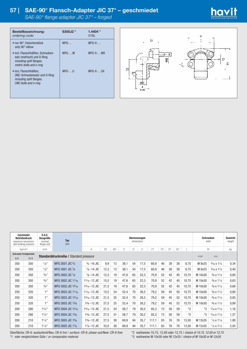
Oberfläche: CR-6: auslaufend/Neu: CR-6 frei / surface: CR-6: phase-out/New: CR-6 free*1 oder vergleichbare Güte / or comparable material
*2 wahlweise 10,75, 12,00 oder 12,75 / choice of 10.75, 12.00 or 12.75 *3 wahlweise M 10x30 oder M 12x35 / choice of M 10x30 or M 12x35
Bestellbezeichnung:ordering code:
S355J2 *1
1.4404 *1
316L
• nur 90° Zwischenstück only 90° elbow
WFG-… WFG-X-…
• incl. Flanschhälften, Schrauben-satz (metrisch) und O-Ring including split flanges, metric bolts and o-ring
WFG-…M WFG-X-…MX
• incl. Flanschhälften, UNC-Schraubensatz und O-Ring including split flanges, UNC bolts and o-ring
WFG-…U WFG-X-…UX
57 | SAE-90° Flansch-Adapter JIC 37° – geschmiedet SAE-90° flange adapter JIC 37° – forged
maximaler Betriebsdruck
maximum recommen-ded working pressure
S.A.E. Baugröße
nominal flange size
Typtype
Abmessungendimensions
Schraubenbolts
Gewichtweight
kg/cm² inch A B1 B2 C D E F1 F2 S1 S2 L M kg
Schraube Festigkeitskl.Standarddruckreihe / Standard pressure metr. unc.
8.8 10.9
350 350 ¹ ⁄₂" WFG 3001 JIC ³⁄₄ ³⁄₄ -16 JIC 9,9 13 38,1 54 17,5 60,8 46 38 38 8,75 M 8x25 ⁵⁄₁₆ x 1¹⁄₄ 0,34
350 350 ¹ ⁄₂" WFG 3001 JIC ⁷⁄₈ ⁷⁄₈ -14 JIC 12,3 13 38,1 54 17,5 60,8 46 38 38 8,75 M 8x25 ⁵⁄₁₆ x 1¹⁄₄ 0,40
350 350 ³⁄₄" WFG 3002 JIC ⁷⁄₈ ⁷⁄₈ -14 JIC 12,3 19 47,6 65 22,3 70,9 52 42 45 10,75 M 10x30 ³⁄₈ x 1¹ ⁄₂ 0,60
350 350 ³⁄₄" WFG 3002 JIC 1¹⁄₁₆ 1¹⁄₁₆ -12 JIC 15,5 19 47,6 65 22,3 70,9 52 42 45 10,75 M 10x30 ³⁄₈ x 1¹ ⁄₂ 0,63
350 350 ³⁄₄" WFG 3002 JIC 1⁵⁄₁₆ 1⁵⁄₁₆ -12 JIC 21,5 19 47,6 65 22,3 70,9 52 42 45 10,75 M 10x30 ³⁄₈ x 1¹ ⁄₂ 0,66
250 320 1" WFG 3003 JIC 1¹⁄₁₆ 1¹⁄₁₆ -12 JIC 15,5 24 52,4 70 26,2 79,2 59 45 50 10,75 M 10x30 ³⁄₈ x 1¹ ⁄₂ 0,80
250 320 1" WFG 3003 JIC 1⁵⁄₁₆ 1⁵⁄₁₆ -12 JIC 21,5 25 52,4 70 26,2 79,2 59 45 52 10,75 M 10x30 ³⁄₈ x 1¹ ⁄₂ 0,85
250 320 1" WFG 3003 JIC 1⁵⁄₈ 1⁵⁄₈ -12 JIC 27,5 25 52,4 70 26,2 79,2 59 45 52 10,75 M 10x30 ³⁄₈ x 1¹ ⁄₂ 0,89
200 280 1¹⁄₄" WFG 3004 JIC 1⁵⁄₁₆ 1⁵⁄₁₆ -12 JIC 21,5 24 58,7 79 30,2 85,3 73 50 59 *2 *3 ⁷⁄₁₆ x 1¹ ⁄₂ 1,16
200 280 1¹⁄₄" WFG 3004 JIC 1⁵⁄₈ 1⁵⁄₈ -12 JIC 27,5 31 58,7 79 30,2 85,3 73 50 59 *2 *3 ⁷⁄₁₆ x 1¹ ⁄₂ 1,27
200 210 1¹ ⁄₂" WFG 3005 JIC 1⁵⁄₈ 1⁵⁄₈ -12 JIC 27,5 38 69,9 94 35,7 117,1 83 76 76 13,50 M 12x35 ¹ ⁄₂ x 1¹ ⁄₂ 1,90
200 210 1¹ ⁄₂" WFG 3005 JIC 1⁷⁄₈ 1⁷⁄₈ -12 JIC 33,0 38 69,9 94 35,7 117,1 83 76 76 13,50 M 12x35 ¹ ⁄₂ x 1¹ ⁄₂ 2,05

Oberfläche: CR-6: auslaufend/Neu: CR-6 frei / surface: CR-6: phase-out/New: CR-6 free*1 oder vergleichbare Güte / or comparable material
*2 wahlweise 12,0 oder 13,0 / choice of 12.0 or 13.0 *3 wahlweise 13,5 oder 14,75 / choice of 13.5 or 14.75
Bestellbezeichnung:ordering code:
S355J2 *1
1.4404 *1
316L
• nur 90° Zwischenstück only 90° elbow
WFG-… WFG-X-…
• incl. Flanschhälften, Schrauben-satz (metrisch) und O-Ring including split flanges, metric bolts and o-ring
WFG-…M WFG-X-…MX
• incl. Flanschhälften, UNC-Schraubensatz und O-Ring including split flanges, UNC bolts and o-ring
WFG-…U WFG-X-…UX
58 | SAE-90° Flansch-Adapter JIC 37° – geschmiedet SAE-90° flange adapter JIC 37° – forged
maximaler Betriebsdruck
maximum recommen-ded working pressure
S.A.E. Baugröße
nominal flange size
Typtype
Abmessungendimensions
Schraubenbolts
Gewichtweight
kg/cm² inch A B1 B2 C D E F1 F2 S1 S2 L M kg
Schraube Festigkeitskl.Hochdruckreihe / High pressure metr. unc.
8.8 10.9
350 420 ¹ ⁄₂" WFG 6001 JIC ³⁄₄ ³⁄₄ -16 JIC 9,9 13 40,5 56 18,2 61,6 48 39 38 8,75 M 8x30 ⁵⁄₁₆ x 1¹⁄₄ 0,37
350 420 ¹ ⁄₂" WFG 6001 JIC ⁷⁄₈ ⁷⁄₈ -14 JIC 12,3 13 40,5 56 18,2 61,6 48 39 38 8,75 M 8x35 ⁵⁄₁₆ x 1¹⁄₄ 0,45
350 420 ³⁄₄" WFG 6002 JIC ⁷⁄₈ ⁷⁄₈ -14 JIC 12,3 17 50,8 71 23,8 78,0 60 48 48 10,75 M 10x35 ³⁄₈ x 1¹ ⁄₂ 0,88
350 420 ³⁄₄" WFG 6002 JIC 1¹⁄₁₆ 1¹⁄₁₆ -12 JIC 15,5 17 50,8 71 23,8 78,0 60 48 48 10,75 M 10x35 ³⁄₈ x 1¹ ⁄₂ 0,97
350 420 ³⁄₄" WFG 6002 JIC 1⁵⁄₁₆ 1⁵⁄₁₆ -12 JIC 21,5 17 50,8 71 23,8 78,0 60 48 48 10,75 M 10x35 ³⁄₈ x 1¹ ⁄₂ 1,02
350 420 1" WFG 6003 JIC 1¹⁄₁₆ 1¹⁄₁₆ -12 JIC 15,5 24 57,2 81 27,8 99,0 70 60 60 *2 M 12x45 ⁷⁄₁₆ x 1³⁄₄ 1,46
350 420 1" WFG 6003 JIC 1⁵⁄₁₆ 1⁵⁄₁₆ -12 JIC 21,5 24 57,2 81 27,8 99,0 70 60 60 *2 M 12x45 ⁷⁄₁₆ x 1³⁄₄ 1,57
350 420 1" WFG 6003 JIC 1⁵⁄₈ 1⁵⁄₈ -12 JIC 27,5 24 57,2 81 27,8 99,0 70 60 60 *2 M 12x45 ⁷⁄₁₆ x 1³⁄₄ 1,70
350 420 1¹⁄₄" WFG 6004 JIC 1⁵⁄₁₆ 1⁵⁄₁₆ -12 JIC 21,5 31 66,6 95 31,8 115,5 78 68 68 *3 M 14x50 ¹ ⁄₂ x 1³⁄₄ 2,20
350 420 1¹⁄₄" WFG 6004 JIC 1⁵⁄₈ 1⁵⁄₈ -12 JIC 27,5 31 66,6 95 31,8 115,5 78 68 68 *3 M 14x50 ¹ ⁄₂ x 1³⁄₄ 2,30
350 420 1¹⁄₄" WFG 6004 JIC 1⁷⁄₈ 1⁷⁄₈ -12 JIC 33,0 30 66,6 95 31,8 115,5 78 68 68 *3 M 14x50 ¹ ⁄₂ x 1³⁄₄ 2,45
350 420 1¹ ⁄₂" WFG 6005 JIC 1⁵⁄₈ 1⁵⁄₈ -12 JIC 27,5 32 79,3 113 36,5 133,0 95 76 76 17,00 M 16x55 ⁵⁄₈ x 2 3,08
350 420 1¹ ⁄₂" WFG 6005 JIC 1⁷⁄₈ 1⁷⁄₈ -12 JIC 33,0 32 79,3 113 36,5 133,0 95 76 76 17,00 M 16x55 ⁵⁄₈ x 2 3,45

*1 oder vergleichbare Güte / or comparable material*2 L=13,5 für UNC-Schrauben / L=13.5 with UNC-bolts
Bestellbezeichnung:ordering code:
S355J2 *1
1.4404 *1
316L
• nur Flansch flange only
AFS-…/90S AFX-…/90S
• incl. metrischem Schraubensatz und O-Ring including metric bolts and o-ring
AFS-…/90SM AFX-…/90SM
• incl. UNC-Schraubensatz und O-Ring including UNC bolts and o-ring
AFS-…/90SU AFX-…/90SUX
59 | SAE-90° Einschweißflansch SAE-90° socket weld flange
maximaler Betriebsdruck
maximum recommen-ded working pressure
S.A.E. Baugröße
nominal flange size
Typtype
Abmessungendimensions
Schraubenbolts
Gewichtweight
kg/cm² inch A B1/B2 C D E F1 F2 H I L S1 S2 M kg
Schraube Festigkeitskl.Standarddruckreihe / Standard pressure metr. unc.
8.8 10.9
350 350 ¹ ⁄₂" AFS 080/90 S 21,6 13 38,1 54 17,5 60 43 16 10 9,0 20 37 M 8x30 ⁵⁄₁₆ x 1¹⁄₄ 0,35
350 350 ¹ ⁄₂" AFS 080/90 S-038 17,5 13 38,1 54 17,5 60 43 16 10 9,0 20 37 M 8x30 ⁵⁄₁₆ x 1¹⁄₄ 0,35
350 350 ³⁄₄" AFS 100/90 S 27,2 19 47,6 65 22,3 63 47 18 10 11,0 24 38 M 10x35 ³⁄₈ x 1¹ ⁄₂ 0,55
250 320 1" AFS 102/90 S 34,0 25 52,4 70 26,2 70 51 19 12 11,0 28 43 M 10x35 ³⁄₈ x 1¹ ⁄₂ 0,80
200 280 1¹⁄₄" AFS 104/90 S 42,8 27/32 58,7 79 30,2 85 64 21 14 11,5 34 51 M 10x40 ⁷⁄₁₆ x 1¹ ⁄₂ 1,30
200 210 1¹ ⁄₂" AFS 106/90 S 48,6 34/38 69,9 93 35,7 95 74 25 16 13,5 38 56 M 12x45 ¹ ⁄₂ x 1³⁄₄ 1,60
160 210 2" AFS 108/90 S 61,0 49/51 77,8 110 42,9 110 85 25 18 13,5 42 65 M 12x45 ¹ ⁄₂ x 1³⁄₄ 2,00
100 175 2¹ ⁄₂" AFS 110/90 S 76,6 57/60 88,9 115 50,8 127 96 25 30 13,5 50 77 M 12x45 ¹ ⁄₂ x 1³⁄₄ –Schraube Festigkeitskl.
Hochdruckreihe / High pressure metr. unc.8.8 10.9
350 420 ¹ ⁄₂" AFS 401/90 S-012 21,6 13 40,5 54 18,2 60 43 16 10 9,0 20 37 M 8x30 ⁵⁄₁₆ x 1¹⁄₄ 0,35
350 420 ¹ ⁄₂" AFS 401/90 S-038 17,5 13 40,5 54 18,2 60 43 16 10 9,0 20 37 M 8x30 ⁵⁄₁₆ x 1¹⁄₄ 0,35
350 420 ³⁄₄" AFS 402/90 S 27,2 19 50,8 70 23,8 70 51 19 12 11,0 28 43 M 10x35 ³⁄₈ x 1¹ ⁄₂ 0,80
350 420 ³⁄₄" AFS 402/90 S 20 20,2 16/19 50,8 70 23,8 70 51 19 14 11,0 28 43 M 10x35 ³⁄₈ x 1¹ ⁄₂ –
350 420 ³⁄₄" AFS 402/90 S 25 25,1 19 50,8 70 23,8 70 51 19 14 11,0 28 43 M 10x35 ³⁄₈ x 1¹ ⁄₂ –
350 420 ³⁄₄" AFS 402/90 S 30 30,1 25/19 50,8 70 23,8 70 51 19 14 11,0 28 43 M 10x35 ³⁄₈ x 1¹ ⁄₂ –
350 420 1" AFS 403/90 S 34,0 25 57,2 79 27,8 85 64 21 14 13,0 34 51 M 12x45 ⁷⁄₁₆ x 1³⁄₄ 1,30
350 420 1" AFS 403/90 S 30 30,2 22/25 57,2 79 27,8 85 64 21 14 13,0 34 51 M 12x45 ⁷⁄₁₆ x 1³⁄₄ –
350 420 1¹⁄₄" AFS 404/90 S 42,8 32 66,6 93 31,8 95 74 25 16 15,0*2 38 56 M 14x50 ¹ ⁄₂ x 1³⁄₄ 1,60
350 420 1¹⁄₄" AFS 404/90 S 30 30,2 22/32 66,6 93 31,8 95 74 25 14 15,0*2 38 56 M 14x50 ¹ ⁄₂ x 1³⁄₄ –
350 420 1¹⁄₄" AFS 404/90 S 38 38,2 27/32 66,6 93 31,8 95 74 25 14 15,0*2 38 56 M 14x50 ¹ ⁄₂ x 1³⁄₄ –
350 420 1¹ ⁄₂" AFS 405/90 S 48,6 38 79,3 110 36,5 110 85 25 18 17,5 42 65 M 16x50 ⁵⁄₈ x 2 2,00
350 420 2" AFS 406/90 S 61,0 51 96,8 134 44,5 132 107 35 25 21,0 45 75 M 20x70 – 3,85

Bestellbezeichnung:ordering code:
S355J2 *1
1.4404 *1
316L
• nur Flansch flange only
GFS-…/90S GFX-…/90S
60 | SAE-90° Einschweiß-Gegenflansch SAE-90° socket weld flange companion
*1 oder vergleichbare Güte / or comparable material
maximaler Betriebsdruck
maximum recommen-ded working pressure
S.A.E. Baugröße
nominal flange size
Typtype
Abmessungendimensions
Gewindethread
Gewichtweight
kg/cm² inch A B1/B2 C D E F1 F2 H I S1 S2 M kg
Schraube Festigkeitskl.Standarddruckreihe / Standard pressure metr. unc.
8.8 10.9
350 350 ¹ ⁄₂" GFS 080/90 S 21,6 13 38,1 54 17,5 60 48 16,0 10 20 37 M 8 ⁵⁄₁₆ 0,35
350 350 ¹ ⁄₂" GFS 080/90 S-038 17,5 13 38,1 54 17,5 60 48 16,0 10 20 37 M 8 ⁵⁄₁₆ 0,35
350 350 ³⁄₄" GFS 100/90 S 27,2 19 47,6 65 22,3 63 50 18,0 10 24 38 M 10 ³⁄₈ 0,55
250 320 1" GFS 102/90 S 34,0 25 52,4 70 26,2 70 60 19,0 12 28 43 M 10 ³⁄₈ 0,80
200 280 1¹⁄₄" GFS 104/90 S 42,8 27/32 58,7 79 30,2 85 68 21,0 14 34 51 M 10 ⁷⁄₁₆ 1,30
200 210 1¹ ⁄₂" GFS 106/90 S 48,6 34/38 69,9 93 35,7 95 78 25,0 16 38 56 M 12 ¹ ⁄₂ 1,60
160 210 2" GFS 108/90 S 61,0 49/51 77,8 110 42,9 110 90 25,0 18 42 65 M 12 ¹ ⁄₂ 2,00Schraube Festigkeitskl.
Hochdruckreihe / High pressure metr. unc.8.8 10.9
350 420 ¹ ⁄₂" GFS 401/90 S-012 21,6 13 40,5 54 18,2 60 48 16,0 10 20 37 M 8 ⁵⁄₁₆ 0,35
350 420 ¹ ⁄₂" GFS 401/90 S-038 17,5 13 40,5 54 18,2 60 48 16,0 10 20 37 M 8 ⁵⁄₁₆ 0,35
350 420 ³⁄₄" GFS 402/90 S 27,2 19 50,8 70 23,8 70 60 19,0 12 28 43 M 10 ³⁄₈ 0,80
350 420 ³⁄₄" GFS 402/90 S 25 25,1 19 50,8 70 23,8 70 51 19,0 14 28 43 M 10 ³⁄₈ –
350 420 1" GFS 403/90 S 34,0 25 57,2 79 27,8 85 70 21,0 14 34 51 M 12 ⁷⁄₁₆ 1,30
350 420 1" GFS 403/90 S 30 30,2 22/25 57,2 79 27,8 85 74 21,0 14 34 51 M 12 ⁷⁄₁₆ –
350 420 1¹⁄₄" GFS 404/90 S 42,8 32 66,6 93 31,8 95 78 25,0 16 38 56 M 14 ¹ ⁄₂ 1,60
350 420 1¹ ⁄₂" GFS 405/90 S 48,6 38 79,3 110 36,5 110 94 25,0 18 42 65 M 16 ⁵⁄₈ 2,00
350 420 2" GFS 406/90 S 61,0 51 96,8 134 44,5 150 106 35,0 18 45 92 M 20 – 8,20

*1 oder vergleichbare Güte / or comparable material
Bestellbezeichnung:ordering code:
S355J2 *1
• nur Flansch flange only
AFS-…/90ST
• incl. metrischem Schraubensatz und O-Ring including metric bolts and o-ring
AFS-…/90STM
61 | SAE-90° Anschweißflansch – zöllig SAE-90° weld-on flange – inches
* Der angeführte maximale Betriebsdruck ist bezogen auf den Flansch! Der tatsächliche Betriebsdruck wird bestimmt durch das Rohr (Wandstärke) sowie die Güte des Rohres! The maximum recommended working pressure is based on the flange. The working pressure of the system is determined by the tube (thickness) and by the steel quality of the tube!
maximaler Betriebsdruck *
maximum recommen-ded working pressure
S.A.E. Baugröße
nominal flange size
Typtype
Abmessungendimensions
Schraubenbolts
Gewichtweight
kg/cm² inch A B C D E F1 F2 H L S1 S2 M kg
Schraube Festigkeitskl.Standarddruckreihe / Standard pressure metr. unc.
8.8 10.9
350 350 ³⁄₄" AFS 200/90 ST 27,0 19 47,6 70 22,3 63 50 21,0 11,0 23,0 41 M 10x40 – 0,65
250 320 1" AFS 202/90 ST 34,5 23 52,4 75 26,2 72 60 24,0 11,0 25,0 48 M 10x45 – 0,85
200 280 1¹⁄₄" AFS 204/90 ST 43,0 31 58,7 86 30,2 82 68 25,0 11,5 27,0 54 M 10x45 – 1,15
200 210 1¹ ⁄₂" AFS 206/90 ST 50,0 35 69,9 97 35,7 92 78 29,0 14,0 31,5 57 M 12x50 – 1,70
160 210 2" AFS 208/90 ST 65,0 48 77,8 100 42,9 99 90 50,0 14,0 37,5 63 M 12x70 – 2,15Schraube Festigkeitskl.
Hochdruckreihe / High pressure metr. unc.8.8 10.9
350 420 ³⁄₄" AFS 700/90 ST 28,0 19 50,8 71 23,8 70 60 19,0 11,0 22,0 40 M 10x35 – 0,50
350 420 1" AFS 702/90 ST 34,0 25 57,2 81 27,8 82 70 24,0 13,0 27,0 47 M 12x45 – 0,80
350 375 1¹⁄₄" AFS 704/90 ST 42,0 32 66,6 95 31,8 95 78 27,0 15,0 32,0 56 M 14x50 – 1,15
320 320 1¹ ⁄₂" AFS 706/90 ST 48,0 38 79,3 113 36,5 115 94 30,0 17,0 40,0 68 M 16x50 – 2,00
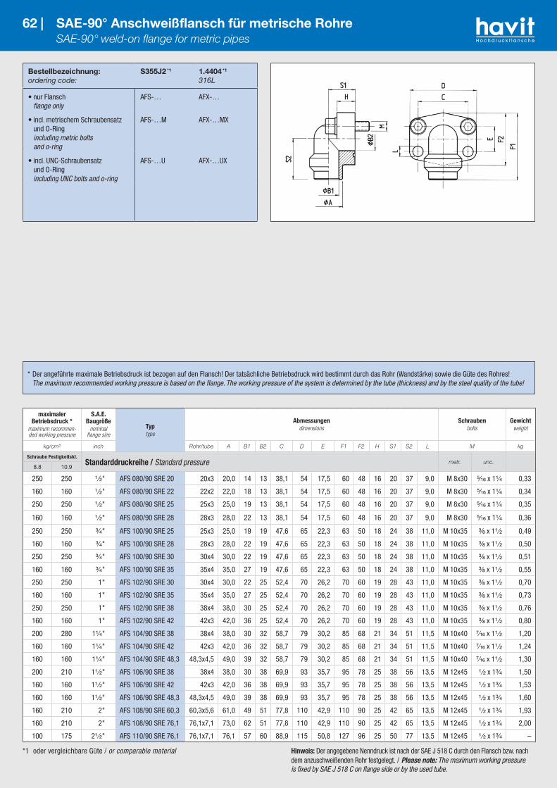
Bestellbezeichnung:ordering code:
S355J2 *1
1.4404 *1
316L
• nur Flansch flange only
AFS-… AFX-…
• incl. metrischem Schraubensatz und O-Ring including metric bolts and o-ring
AFS-…M AFX-…MX
• incl. UNC-Schraubensatz und O-Ring including UNC bolts and o-ring
AFS-…U AFX-…UX
62 | SAE-90° Anschweißflansch für metrische Rohre SAE-90° weld-on flange for metric pipes
*1 oder vergleichbare Güte / or comparable material Hinweis: Der angegebene Nenndruck ist nach der SAE J 518 C durch den Flansch bzw. nach dem anzuschweißenden Rohr festgelegt. / Please note: The maximum working pressure is fixed by SAE J 518 C on flange side or by the used tube.
* Der angeführte maximale Betriebsdruck ist bezogen auf den Flansch! Der tatsächliche Betriebsdruck wird bestimmt durch das Rohr (Wandstärke) sowie die Güte des Rohres! The maximum recommended working pressure is based on the flange. The working pressure of the system is determined by the tube (thickness) and by the steel quality of the tube!
maximaler Betriebsdruck *
maximum recommen-ded working pressure
S.A.E. Baugröße
nominal flange size
Typtype
Abmessungendimensions
Schraubenbolts
Gewichtweight
kg/cm² inch Rohr/tube A B1 B2 C D E F1 F2 H S1 S2 L M kg
Schraube Festigkeitskl.Standarddruckreihe / Standard pressure metr. unc.
8.8 10.9
250 250 ¹ ⁄₂" AFS 080/90 SRE 20 20x3 20,0 14 13 38,1 54 17,5 60 48 16 20 37 9,0 M 8x30 ⁵⁄₁₆ x 1¹⁄₄ 0,33
160 160 ¹ ⁄₂" AFS 080/90 SRE 22 22x2 22,0 18 13 38,1 54 17,5 60 48 16 20 37 9,0 M 8x30 ⁵⁄₁₆ x 1¹⁄₄ 0,34
250 250 ¹ ⁄₂" AFS 080/90 SRE 25 25x3 25,0 19 13 38,1 54 17,5 60 48 16 20 37 9,0 M 8x30 ⁵⁄₁₆ x 1¹⁄₄ 0,35
160 160 ¹ ⁄₂" AFS 080/90 SRE 28 28x3 28,0 22 13 38,1 54 17,5 60 48 16 20 37 9,0 M 8x30 ⁵⁄₁₆ x 1¹⁄₄ 0,36
250 250 ³⁄₄" AFS 100/90 SRE 25 25x3 25,0 19 19 47,6 65 22,3 63 50 18 24 38 11,0 M 10x35 ³⁄₈ x 1¹ ⁄₂ 0,49
160 160 ³⁄₄" AFS 100/90 SRE 28 28x3 28,0 22 19 47,6 65 22,3 63 50 18 24 38 11,0 M 10x35 ³⁄₈ x 1¹ ⁄₂ 0,50
250 250 ³⁄₄" AFS 100/90 SRE 30 30x4 30,0 22 19 47,6 65 22,3 63 50 18 24 38 11,0 M 10x35 ³⁄₈ x 1¹ ⁄₂ 0,51
160 160 ³⁄₄" AFS 100/90 SRE 35 35x4 35,0 27 19 47,6 65 22,3 63 50 18 24 38 11,0 M 10x35 ³⁄₈ x 1¹ ⁄₂ 0,55
250 250 1" AFS 102/90 SRE 30 30x4 30,0 22 25 52,4 70 26,2 70 60 19 28 43 11,0 M 10x35 ³⁄₈ x 1¹ ⁄₂ 0,70
160 160 1" AFS 102/90 SRE 35 35x4 35,0 27 25 52,4 70 26,2 70 60 19 28 43 11,0 M 10x35 ³⁄₈ x 1¹ ⁄₂ 0,73
250 250 1" AFS 102/90 SRE 38 38x4 38,0 30 25 52,4 70 26,2 70 60 19 28 43 11,0 M 10x35 ³⁄₈ x 1¹ ⁄₂ 0,76
160 160 1" AFS 102/90 SRE 42 42x3 42,0 36 25 52,4 70 26,2 70 60 19 28 43 11,0 M 10x35 ³⁄₈ x 1¹ ⁄₂ 0,80
200 280 1¹⁄₄" AFS 104/90 SRE 38 38x4 38,0 30 32 58,7 79 30,2 85 68 21 34 51 11,5 M 10x40 ⁷⁄₁₆ x 1¹ ⁄₂ 1,20
160 160 1¹⁄₄" AFS 104/90 SRE 42 42x3 42,0 36 32 58,7 79 30,2 85 68 21 34 51 11,5 M 10x40 ⁷⁄₁₆ x 1¹ ⁄₂ 1,24
160 160 1¹⁄₄" AFS 104/90 SRE 48,3 48,3x4,5 49,0 39 32 58,7 79 30,2 85 68 21 34 51 11,5 M 10x40 ⁷⁄₁₆ x 1¹ ⁄₂ 1,30
200 210 1¹ ⁄₂" AFS 106/90 SRE 38 38x4 38,0 30 38 69,9 93 35,7 95 78 25 38 56 13,5 M 12x45 ¹ ⁄₂ x 1³⁄₄ 1,50
160 160 1¹ ⁄₂" AFS 106/90 SRE 42 42x3 42,0 36 38 69,9 93 35,7 95 78 25 38 56 13,5 M 12x45 ¹ ⁄₂ x 1³⁄₄ 1,53
160 160 1¹ ⁄₂" AFS 106/90 SRE 48,3 48,3x4,5 49,0 39 38 69,9 93 35,7 95 78 25 38 56 13,5 M 12x45 ¹ ⁄₂ x 1³⁄₄ 1,60
160 210 2" AFS 108/90 SRE 60,3 60,3x5,6 61,0 49 51 77,8 110 42,9 110 90 25 42 65 13,5 M 12x45 ¹ ⁄₂ x 1³⁄₄ 1,93
160 210 2" AFS 108/90 SRE 76,1 76,1x7,1 73,0 62 51 77,8 110 42,9 110 90 25 42 65 13,5 M 12x45 ¹ ⁄₂ x 1³⁄₄ 2,00
100 175 2¹ ⁄₂" AFS 110/90 SRE 76,1 76,1x7,1 76,1 57 60 88,9 115 50,8 127 96 25 50 77 13,5 M 12x45 ¹ ⁄₂ x 1³⁄₄ –
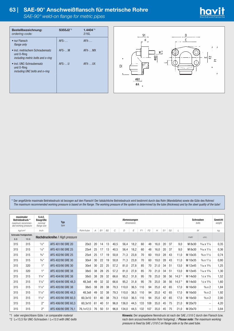
Bestellbezeichnung:ordering code:
S355J2 *1
1.4404 *1
316L
• nur Flansch flange only
AFS-… AFX-…
• incl. metrischem Schraubensatz und O-Ring including metric bolts and o-ring
AFS-…M AFX-…MX
• incl. UNC-Schraubensatz und O-Ring including UNC bolts and o-ring
AFS-…U AFX-…UX
63 | SAE-90° Anschweißflansch für metrische Rohre SAE-90° weld-on flange for metric pipes
* Der angeführte maximale Betriebsdruck ist bezogen auf den Flansch! Der tatsächliche Betriebsdruck wird bestimmt durch das Rohr (Wandstärke) sowie die Güte des Rohres! The maximum recommended working pressure is based on the flange. The working pressure of the system is determined by the tube (thickness) and by the steel quality of the tube!
*1 oder vergleichbare Güte / or comparable material*2 L=13,5 für UNC-Schrauben / L=13.5 with UNC-bolts
Hinweis: Der angegebene Nenndruck ist nach der SAE J 518 C durch den Flansch bzw. nach dem anzuschweißenden Rohr festgelegt. / Please note: The maximum working pressure is fixed by SAE J 518 C on flange side or by the used tube.
maximaler Betriebsdruck *
maximum recommen-ded working pressure
S.A.E. Baugröße
nominal flange size
Typtype
Abmessungendimensions
Schraubenbolts
Gewichtweight
kg/cm² inch Rohr/tube A B1 B2 C D E F1 F2 H S1 S2 L M kg
Schraube Festigkeitskl.Hochdruckreihe / High pressure metr. unc.
8.8 10.9
315 315 ¹ ⁄₂" AFS 401/90 SRE 20 20x3 20 14 13 40,5 56,4 18,2 60 48 16,0 20 37 9,0 M 8x30 ⁵⁄₁₆ x 1¹⁄₄ 0,35
315 315 ¹ ⁄₂" AFS 401/90 SRE 25 25x4 25 17 13 40,5 56,4 18,2 60 48 16,0 20 37 9,0 M 8x30 ⁵⁄₁₆ x 1¹⁄₄ 0,36
315 315 ³⁄₄" AFS 402/90 SRE 25 25x4 25 17 19 50,8 71,3 23,8 70 60 19,0 28 43 11,0 M 10x35 ³⁄₈ x 1¹ ⁄₂ 0,74
315 315 ³⁄₄" AFS 402/90 SRE 30 30x4 30 22 19 50,8 71,3 23,8 70 60 19,0 28 43 11,0 M 10x35 ³⁄₈ x 1¹ ⁄₂ 0,80
315 320 1" AFS 403/90 SRE 30 30x4 30 22 25 57,2 81,0 27,8 85 70 21,0 34 51 13,0 M 12x45 ⁷⁄₁₆ x 1³⁄₄ 1,25
315 320 1" AFS 403/90 SRE 38 38x5 38 28 25 57,2 81,0 27,8 85 70 21,0 34 51 13,0 M 12x45 ⁷⁄₁₆ x 1³⁄₄ 1,30
315 315 1¹⁄₄" AFS 404/90 SRE 38 38x5 38 28 32 66,6 95,2 31,8 95 78 25,0 38 56 14,5 *2 M 14x50 ¹ ⁄₂ x 1³⁄₄ 1,52
315 315 1¹⁄₄" AFS 404/90 SRE 48,3 48,3x8 49 32 32 66,6 95,2 31,8 95 78 25,0 38 56 14,5 *2 M 14x50 ¹ ⁄₂ x 1³⁄₄ 1,60
315 315 1¹ ⁄₂" AFS 405/90 SRE 38 38x5 38 28 38 79,3 110,0 36,5 110 94 25,0 42 65 17,0 M 16x50 ⁵⁄₈ x 2 1,84
315 315 1¹ ⁄₂" AFS 405/90 SRE 48,3 48,3x8 49 32 38 79,3 110,0 36,5 110 94 25,0 42 65 17,0 M 16x50 ⁵⁄₈ x 2 1,92
315 315 1¹ ⁄₂" AFS 405/90 SRE 60,3 60,3x10 61 40 38 79,3 110,0 36,5 110 94 25,0 42 65 17,0 M 16x50 ⁵⁄₈ x 2 2,00
315 315 2" AFS 406/90 SRE 60,3 60,3x10 61 40 51 96,8 136,0 44,5 133 108 35,0 45 75 21,0 M 20x70 – 4,20
315 315 2" AFS 406/90 SRE 76,1 76,1x12,5 76 50 51 96,8 134,0 44,5 132 107 35,0 45 75 21,0 M 20x70 – 3,84

*1 oder vergleichbare Güte / or comparable material*2 Rohrabmessung 38x8 für max. Betriebsdruck 350/400 einsetzbar / Implemented pipe dimensions 38x8 for max. working pressure 350/400
Bestellbezeichnung:ordering code:
S355J2 *1
1.4404 *1
316L
• nur 90° Zwischenstück only 90° elbow
WFS-… WFS-X-…
• incl. Flanschhälften, Schraubensatz (metrisch) und O-Ring including split flanges, metric bolts and o-ring
WFS-…M WFS-X-…MX
• incl. Flanschhälften, UNC-Schraubensatz und O-Ring including split flanges, UNC bolts and o-ring
WFS-…U WFS-X-…UX
64 | SAE-90° Anschweißflansch-Adapter für metrische Rohre SAE-90° weld-on flange adapter for metric pipes
maximaler Betriebsdruck *
maximum recommen-ded working pressure
S.A.E. Baugröße
nominal flange size
Typtype
Abmessungendimensions
Schraubenbolts
Gewichtweight
kg/cm² inch C D E F1/F2 S1/S2 L M kg
Schraube Festigkeitskl.Standarddruckreihe / Standard pressure metr. unc.
8.8 10.9
350 350 ¹ ⁄₂" WFS 3001 38,1 54 17,5 60,8/45,6 39/38 8,75 M 8x25 ⁵⁄₁₆ x 1¹⁄₄ –
A x S = 15 x 2 – 16 x 2 – 21,3 x 3,8
350 350 ³⁄₄" WFS 3002 47,6 65 22,3 70,9/51,8 42/45 10,75 M 10x30 ³⁄₈ x 1¹⁄₄ –
A x S = 18 x 1,5 – 20 x 3 – 22 x 3 – 25 x 3 – 26,9 x 3,9
250 320 1" WFS 3003 52,4 70 26,2 79,2/58,4 45/50 10,75 M 10x30 ³⁄₈ x 1¹⁄₄ –
A x S = 25 x 3 – 30 x 4 – 33,7 x 4,5
200 280 1¹⁄₄" WFS 3004 58,7 79 30,2 85,3/72,6 50/59 10,75/12,75M 10x30
M 12x35⁷⁄₁₆ x 1¹ ⁄₂ –
A x S = 25 x 3 – 30 x 4 – 35 x 2 – 38 x 5 – 42,4 x 5
200 210 1¹ ⁄₂" WFS 3005 69,9 94 35,7 117,1/82,2 76/56 13,5 M 12x35 ¹ ⁄₂ x 1¹ ⁄₂ –
A x S = 38 x 5 – 42 x 3 – 48,3 x 5Schraube Festigkeitskl.
Hochdruckreihe / High pressure metr. unc.8.8 10.9
350 420 ¹ ⁄₂" WFS-6001 40,5 56 18,2 61,6/47,2 39/38 8,75 M 8x30 ⁵⁄₁₆ x 1¹⁄₄ –
A x S = 16 x 3 – 21,3 x 4,5
350 420 ³⁄₄" WFS-6002 50,8 71 23,8 78/60 48/48 10,75 M 10x35 ³⁄₈ x 1¹ ⁄₂ –
A x S = 16 x 3 – 20 x 4 – 25 x 4 – 26,9 x 5,6
350 420 1" WFS-6003 57,2 81 27,8 94/69,6 60/60 12,0/13,0 M 12x45 ⁷⁄₁₆ x 1³⁄₄ –
A x S = 25 x 4 – 30 x 4 – 33,7 x 4,5 – 33,7 x 6,3
315 315 1¹⁄₄" WFS-6004 *2 66,6 95 31,8 106,6/77,2 68/68 13,5/14,75 M 14x50 ¹ ⁄₂ x 1³⁄₄ –
A x S = 30 x 4 – 38 x 5 – 42,4 x 6,3 – 38 x 8 *2
315 315 1¹ ⁄₂" WFS-6005 *2 79,3 113 36,5 123,5/95 76/76 17,0 M 16x55 ⁵⁄₈ x 2 –
A x S = 38 x 5 – 38 x 8 *2 – 48,3 x 7,14 – 48,3 x 8
* Der angeführte maximale Betriebsdruck ist bezogen auf den Flansch! Der tatsächliche Betriebsdruck wird bestimmt durch das Rohr (Wandstärke) sowie die Güte des Rohres! The maximum recommended working pressure is based on the flange. The working pressure of the system is determined by the tube (thickness) and by the steel quality of the tube!
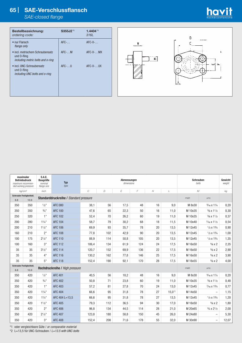
*1 oder vergleichbare Güte / or comparable material*2 L=13,5 für UNC-Schrauben / L=13.5 with UNC-bolts
Bestellbezeichnung:ordering code:
S355J2 *1
1.4404 *1
316L
• nur Flansch flange only
AFC-… AFC-X-…
• incl. metrischem Schraubensatz und O-Ring including metric bolts and o-ring
AFC-…M AFC-X-…MX
• incl. UNC-Schraubensatz und O-Ring including UNC bolts and o-ring
AFC-…U AFC-X-…UX
65 | SAE-Verschlussflansch SAE-closed flange
maximaler Betriebsdruck
maximum recommen-ded working pressure
S.A.E. Baugröße
nominal flange size
Typtype
Abmessungendimensions
Schraubenbolts
Gewichtweight
kg/cm² inch C D E F H L M kg
Schraube Festigkeitskl.Standarddruckreihe / Standard pressure metr. unc.
8.8 10.9
350 350 ¹ ⁄₂" AFC 080 38,1 56 17,5 48 16 9,0 M 8x30 ⁵⁄₁₆ x 1¹⁄₄ 0,20
350 350 ³⁄₄" AFC 100 47,6 65 22,3 50 16 11,0 M 10x35 ³⁄₈ x 1¹ ⁄₂ 0,30
250 320 1" AFC 102 52,4 70 26,2 60 19 11,0 M 10x35 ³⁄₈ x 1¹ ⁄₂ 0,37
200 280 1¹⁄₄" AFC 104 58,7 79 30,2 68 18 11,5 M 10x40 ⁷⁄₁₆ x 1¹ ⁄₂ 0,54
200 210 1¹ ⁄₂" AFC 106 69,9 93 35,7 78 20 13,5 M 12x45 ¹ ⁄₂ x 1³⁄₄ 0,90
160 210 2" AFC 108 77,8 102 42,9 90 20 13,5 M 12x45 ¹ ⁄₂ x 1³⁄₄ 1,00
100 175 2¹ ⁄₂" AFC 110 88,9 114 50,8 105 20 13,5 M 12x45 ¹ ⁄₂ x 1³⁄₄ 1,35
100 160 3" AFC 112 106,4 134 61,9 124 24 17,5 M 16x50 ⁵⁄₈ x 2 2,35
35 35 3¹ ⁄₂" AFC 114 120,7 152 69,9 136 22 17,5 M 16x50 ⁵⁄₈ x 2 2,90
35 35 4" AFC 116 130,2 162 77,8 146 25 17,5 M 16x50 ⁵⁄₈ x 2 3,90
35 35 5" AFC 118 152,4 190 92,1 170 28 17,5 M 16x55 ⁵⁄₈ x 2 4,00Schraube Festigkeitskl.
Hochdruckreihe / High pressure metr. unc.8.8 10.9
350 420 ¹ ⁄₂" AFC 401 40,5 56 18,2 48 16 9,0 M 8x30 ⁵⁄₁₆ x 1¹⁄₄ 0,20
350 420 ³⁄₄" AFC 402 50,8 71 23,8 60 19 11,0 M 10x35 ³⁄₈ x 1¹ ⁄₂ 0,48
350 420 1" AFC 403 57,2 81 27,8 70 24 13,0 M 12x45 ⁷⁄₁₆ x 1³⁄₄ 0,77
350 420 1¹⁄₄" AFC 404 66,6 95 31,8 78 27 15,0 *2 M 14x50 – 1,15
350 420 1¹⁄₄" AFC 404 L=13,5 66,6 95 31,8 78 27 13,5 M 12x45 ¹ ⁄₂ x 1³⁄₄ 1,20
350 420 1¹ ⁄₂" AFC 405 79,3 112 36,5 94 30 17,0 M 16x50 ⁵⁄₈ x 2 1,80
350 420 2" AFC 406 96,8 134 44,5 114 28 21,0 M 20x65 ³⁄₄ x 2¹ ⁄₂ 2,00
350 420 2¹ ⁄₂" AFC 407 123,8 180 58,8 150 45 26,0 M 24x80 – 5,30
350 420 3" AFC 408 152,4 208 71,6 178 55 32,0 M 30x90 – 12,07
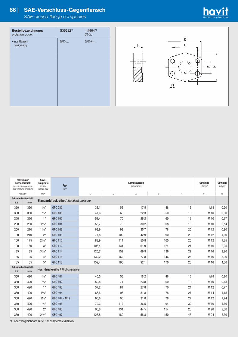
*1 oder vergleichbare Güte / or comparable material
Bestellbezeichnung:ordering code:
S355J2 *1
1.4404 *1
316L
• nur Flansch flange only
GFC-… GFC-X-…
66 | SAE-Verschluss-Gegenflansch SAE-closed flange companion
maximaler Betriebsdruck
maximum recommen-ded working pressure
S.A.E. Baugröße
nominal flange size
Typtype
Abmessungendimensions
Gewindethread
Gewichtweight
kg/cm² inch C D E F H M kg
Schraube Festigkeitskl.Standarddruckreihe / Standard pressure
8.8 10.9
350 350 ¹ ⁄₂" GFC 080 38,1 56 17,5 48 16 M 8 0,20
350 350 ³⁄₄" GFC 100 47,6 65 22,3 50 16 M 10 0,30
250 320 1" GFC 102 52,4 70 26,2 60 19 M 10 0,37
200 280 1¹⁄₄" GFC 104 58,7 79 30,2 68 18 M 10 0,54
200 210 1¹ ⁄₂" GFC 106 69,9 93 35,7 78 20 M 12 0,90
160 210 2" GFC 108 77,8 102 42,9 90 20 M 12 1,00
100 175 2¹ ⁄₂" GFC 110 88,9 114 50,8 105 20 M 12 1,35
100 160 3" GFC 112 106,4 134 61,9 124 24 M 16 2,35
35 35 3¹ ⁄₂" GFC 114 120,7 152 69,9 136 22 M 16 2,90
35 35 4" GFC 116 130,2 162 77,8 146 25 M 16 3,90
35 35 5" GFC 118 152,4 190 92,1 170 28 M 16 4,00Schraube Festigkeitskl.
Hochdruckreihe / High pressure8.8 10.9
350 420 ¹ ⁄₂" GFC 401 40,5 56 18,2 48 16 M 8 0,20
350 420 ³⁄₄" GFC 402 50,8 71 23,8 60 19 M 10 0,48
350 420 1" GFC 403 57,2 81 27,8 70 24 M 12 0,77
350 420 1¹⁄₄" GFC 404 66,6 95 31,8 78 27 M 14 1,15
350 420 1¹⁄₄" GFC 404 - M12 66,6 95 31,8 78 27 M 12 1,24
350 420 1¹ ⁄₂" GFC 405 79,3 112 36,5 94 30 M 16 1,80
350 420 2" GFC 406 96,8 134 44,5 114 28 M 20 2,00
350 420 2¹ ⁄₂" GFC 407 123,8 180 58,8 150 45 M 24 5,30

*1 oder vergleichbare Güte / or comparable material*2 wahlweise 10,75, 12,00 oder 12,75 / choice of 10.75, 12.00 or 12.75 *3 wahlweise M 10x30 oder M 12x35 / choice of M 10x30 or M 12x35
*4 wahlweise 12,0 oder 13,0 / choice of 12.0 or 13.0 *5 wahlweise 13,5 oder 14,75 / choice of 13.5 or 14.75
Bestellbezeichnung:ordering code:
S355J2 *1
1.4404 *1
316L
• nur Blindteller flange plug only
BL-… BL-X-…
• incl. Flanschhälften (oder Voll-flansch), metrischem Schrauben-satz und O-Ring including split flanges (or complete flange), metric bolts and o-ring
BL-…FH-M BL-X-…FH-MX
• incl. Flanschhälften (oder Voll-flansch), UNC-Schraubensatz und O-Ring including split flanges (or complete flange), UNC bolts and o-ring
BL-…FH-U BL-X-…FH-UX
• Blindteller ohne Nut Plug without groove
BLO-…
67 | SAE-Blindstopfen SAE-plugs
maximaler Betriebsdruck
maximum recommen-ded working pressure
S.A.E. Baugröße
nominal flange size
Typtype
Abmessungendimensions
Schraubenbolts
Gewicht (nur Teller)
weight (plug only)
kg/cm² inch A1 C D E F H L M kg
Schraube Festigkeitskl.Standarddruckreihe / Standard pressure metr. unc.
8.8 10.9
210 210 ¹ ⁄₂" BL/BLO 3001 30,2 38,1 54 17,5 46 6,8 8,75 M 8x25 ⁵⁄₁₆ x 1¹⁄₄ 0,03
210 210 ³⁄₄" BL/BLO 3002 38,1 47,6 65 22,3 52 6,8 10,75 M 10x30 ³⁄₈ x 1¹⁄₄ 0,05
210 210 1" BL/BLO 3003 44,5 52,4 70 26,2 59 8,0 10,75 M 10x30 ³⁄₈ x 1¹⁄₄ 0,09
200 210 1¹⁄₄" BL/BLO 3004 50,8 58,7 79 30,2 73 8,0 *2 *3 ⁷⁄₁₆ x 1¹ ⁄₂ 0,12
160 160 1¹ ⁄₂" BL/BLO 3005 60,3 69,9 94 35,7 83 8,0 13,50 M 12x35 ¹ ⁄₂ x 1¹ ⁄₂ 0,17
160 210 2" BL/BLO 3006 71,4 77,8 102 42,9 97 9,6 13,50 M 12x35 ¹ ⁄₂ x 1¹ ⁄₂ 0,29
– – 2¹ ⁄₂" BL/BLO 3007 84,1 88,9 114 50,8 109 9,6 13,50 M 12x35 ¹ ⁄₂ x 1¹ ⁄₂ 0,39
– – 3" BL/BLO 3008 101,6 106,4 135 61,9 131 9,6 17,00 M 16x50 ⁵⁄₈ x 2 0,58
– – 3¹ ⁄₂" BL/BLO 3009 114,3 120,7 152 69,9 140 11,3 17,00 M 16x50 ⁵⁄₈ x 2 0,86
– – 4" BL/BLO 3010 127,0 130,2 162 77,8 152 11,3 17,00 M 16x50 ⁵⁄₈ x 2 1,02
– – 5" BL/BLO 3011 152,4 152,4 185 92,1 181 11,3 17,00 M 16x55 ⁵⁄₈ x 2 1,96Schraube Festigkeitskl.
Hochdruckreihe / High pressure metr. unc.8.8 10.9
250 250 ¹ ⁄₂" BL/BLO 6001 31,8 40,5 56 18,2 48 7,8 8,75 M 8x30 ⁵⁄₁₆ x 1¹⁄₄ 0,04
250 250 ³⁄₄" BL/BLO 6002 41,3 50,8 71 23,8 60 8,8 10,75 M 10x35 ³⁄₈ x 1¹ ⁄₂ 0,09
250 250 1" BL/BLO 6003 47,6 57,2 81 27,8 70 9,5 *4 M 12x45 ⁷⁄₁₆ x 1³⁄₄ 0,13
250 250 1¹⁄₄" BL/BLO 6004 54,0 66,6 95 31,8 78 10,3 *5 M 14x50 ¹ ⁄₂ x 1³⁄₄ 0,18
250 250 1¹ ⁄₂" BL/BLO 6005 63,5 79,3 113 36,5 95 12,6 17,00 M 16x55 ⁵⁄₈ x 2 0,30
250 250 2" BL/BLO 6006 79,4 96,8 133 44,5 114 12,6 21,00 M 20x70 ³⁄₄ x 2¹ ⁄₂ 0,48
– – 2¹ ⁄₂" BL/BLO 6007 108,0 123,8 180 58,8 152 21,2 26,00 M 24x80 – 1,26
– – 3" BL/BLO 6008 132,0 152,4 215 71,6 198 26,5 32,00 M 30x90 – 2,31
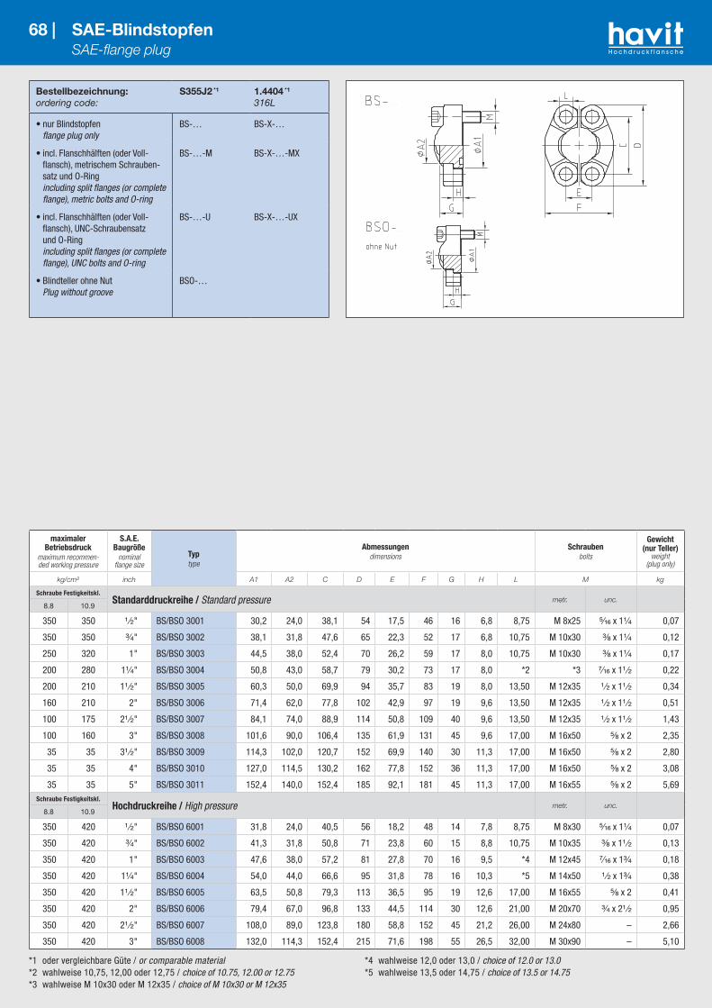
*1 oder vergleichbare Güte / or comparable material*2 wahlweise 10,75, 12,00 oder 12,75 / choice of 10.75, 12.00 or 12.75 *3 wahlweise M 10x30 oder M 12x35 / choice of M 10x30 or M 12x35
*4 wahlweise 12,0 oder 13,0 / choice of 12.0 or 13.0 *5 wahlweise 13,5 oder 14,75 / choice of 13.5 or 14.75
Bestellbezeichnung:ordering code:
S355J2 *1
1.4404 *1
316L
• nur Blindstopfen flange plug only
BS-… BS-X-…
• incl. Flanschhälften (oder Voll-flansch), metrischem Schrauben-satz und O-Ring including split flanges (or complete flange), metric bolts and O-ring
BS-…-M BS-X-…-MX
• incl. Flanschhälften (oder Voll-flansch), UNC-Schraubensatz und O-Ring including split flanges (or complete flange), UNC bolts and O-ring
BS-…-U BS-X-…-UX
• Blindteller ohne Nut Plug without groove
BSO-…
68 | SAE-Blindstopfen SAE-flange plug
maximaler Betriebsdruck
maximum recommen-ded working pressure
S.A.E. Baugröße
nominal flange size
Typtype
Abmessungendimensions
Schraubenbolts
Gewicht (nur Teller)
weight (plug only)
kg/cm² inch A1 A2 C D E F G H L M kg
Schraube Festigkeitskl.Standarddruckreihe / Standard pressure metr. unc.
8.8 10.9
350 350 ¹ ⁄₂" BS/BSO 3001 30,2 24,0 38,1 54 17,5 46 16 6,8 8,75 M 8x25 ⁵⁄₁₆ x 1¹⁄₄ 0,07
350 350 ³⁄₄" BS/BSO 3002 38,1 31,8 47,6 65 22,3 52 17 6,8 10,75 M 10x30 ³⁄₈ x 1¹⁄₄ 0,12
250 320 1" BS/BSO 3003 44,5 38,0 52,4 70 26,2 59 17 8,0 10,75 M 10x30 ³⁄₈ x 1¹⁄₄ 0,17
200 280 1¹⁄₄" BS/BSO 3004 50,8 43,0 58,7 79 30,2 73 17 8,0 *2 *3 ⁷⁄₁₆ x 1¹ ⁄₂ 0,22
200 210 1¹ ⁄₂" BS/BSO 3005 60,3 50,0 69,9 94 35,7 83 19 8,0 13,50 M 12x35 ¹ ⁄₂ x 1¹ ⁄₂ 0,34
160 210 2" BS/BSO 3006 71,4 62,0 77,8 102 42,9 97 19 9,6 13,50 M 12x35 ¹ ⁄₂ x 1¹ ⁄₂ 0,51
100 175 2¹ ⁄₂" BS/BSO 3007 84,1 74,0 88,9 114 50,8 109 40 9,6 13,50 M 12x35 ¹ ⁄₂ x 1¹ ⁄₂ 1,43
100 160 3" BS/BSO 3008 101,6 90,0 106,4 135 61,9 131 45 9,6 17,00 M 16x50 ⁵⁄₈ x 2 2,35
35 35 3¹ ⁄₂" BS/BSO 3009 114,3 102,0 120,7 152 69,9 140 30 11,3 17,00 M 16x50 ⁵⁄₈ x 2 2,80
35 35 4" BS/BSO 3010 127,0 114,5 130,2 162 77,8 152 36 11,3 17,00 M 16x50 ⁵⁄₈ x 2 3,08
35 35 5" BS/BSO 3011 152,4 140,0 152,4 185 92,1 181 45 11,3 17,00 M 16x55 ⁵⁄₈ x 2 5,69Schraube Festigkeitskl.
Hochdruckreihe / High pressure metr. unc.8.8 10.9
350 420 ¹ ⁄₂" BS/BSO 6001 31,8 24,0 40,5 56 18,2 48 14 7,8 8,75 M 8x30 ⁵⁄₁₆ x 1¹⁄₄ 0,07
350 420 ³⁄₄" BS/BSO 6002 41,3 31,8 50,8 71 23,8 60 15 8,8 10,75 M 10x35 ³⁄₈ x 1¹ ⁄₂ 0,13
350 420 1" BS/BSO 6003 47,6 38,0 57,2 81 27,8 70 16 9,5 *4 M 12x45 ⁷⁄₁₆ x 1³⁄₄ 0,18
350 420 1¹⁄₄" BS/BSO 6004 54,0 44,0 66,6 95 31,8 78 16 10,3 *5 M 14x50 ¹ ⁄₂ x 1³⁄₄ 0,38
350 420 1¹ ⁄₂" BS/BSO 6005 63,5 50,8 79,3 113 36,5 95 19 12,6 17,00 M 16x55 ⁵⁄₈ x 2 0,41
350 420 2" BS/BSO 6006 79,4 67,0 96,8 133 44,5 114 30 12,6 21,00 M 20x70 ³⁄₄ x 2¹ ⁄₂ 0,95
350 420 2¹ ⁄₂" BS/BSO 6007 108,0 89,0 123,8 180 58,8 152 45 21,2 26,00 M 24x80 – 2,66
350 420 3" BS/BSO 6008 132,0 114,3 152,4 215 71,6 198 55 26,5 32,00 M 30x90 – 5,10
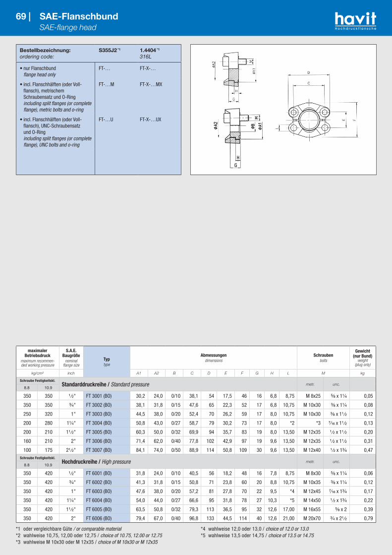
*1 oder vergleichbare Güte / or comparable material*2 wahlweise 10,75, 12,00 oder 12,75 / choice of 10.75, 12.00 or 12.75 *3 wahlweise M 10x30 oder M 12x35 / choice of M 10x30 or M 12x35
*4 wahlweise 12,0 oder 13,0 / choice of 12.0 or 13.0 *5 wahlweise 13,5 oder 14,75 / choice of 13.5 or 14.75
Bestellbezeichnung:ordering code:
S355J2 *1
1.4404 *1
316L
• nur Flanschbund flange head only
FT-… FT-X-…
• incl. Flanschhälften (oder Voll-flansch), metrischem Schraubensatz und O-Ring including split flanges (or complete flange), metric bolts and o-ring
FT-…M FT-X-…MX
• incl. Flanschhälften (oder Voll-flansch), UNC-Schraubensatz und O-Ring including split flanges (or complete flange), UNC bolts and o-ring
FT-…U FT-X-…UX
69 | SAE-Flanschbund SAE-flange head
maximaler Betriebsdruck
maximum recommen-ded working pressure
S.A.E. Baugröße
nominal flange size
Typtype
Abmessungendimensions
Schraubenbolts
Gewicht (nur Bund)
weight (plug only)
kg/cm² inch A1 A2 B C D E F G H L M kg
Schraube Festigkeitskl.Standarddruckreihe / Standard pressure metr. unc.
8.8 10.9
350 350 ¹ ⁄₂" FT 3001 (BO) 30,2 24,0 0/10 38,1 54 17,5 46 16 6,8 8,75 M 8x25 ⁵⁄₈ x 1¹⁄₄ 0,05
350 350 ³⁄₄" FT 3002 (BO) 38,1 31,8 0/15 47,6 65 22,3 52 17 6,8 10,75 M 10x30 ³⁄₈ x 1¹⁄₄ 0,08
250 320 1" FT 3003 (BO) 44,5 38,0 0/20 52,4 70 26,2 59 17 8,0 10,75 M 10x30 ³⁄₈ x 1¹ ⁄₂ 0,12
200 280 1¹⁄₄" FT 3004 (BO) 50,8 43,0 0/27 58,7 79 30,2 73 17 8,0 *2 *3 ⁷⁄₁₆ x 1¹ ⁄₂ 0,13
200 210 1¹ ⁄₂" FT 3005 (BO) 60,3 50,0 0/32 69,9 94 35,7 83 19 8,0 13,50 M 12x35 ¹ ⁄₂ x 1¹ ⁄₂ 0,20
160 210 2" FT 3006 (BO) 71,4 62,0 0/40 77,8 102 42,9 97 19 9,6 13,50 M 12x35 ¹ ⁄₂ x 1¹ ⁄₂ 0,31
100 175 2¹ ⁄₂" FT 3007 (BO) 84,1 74,0 0/50 88,9 114 50,8 109 30 9,6 13,50 M 12x40 ¹ ⁄₂ x 1³⁄₄ 0,47Schraube Festigkeitskl.
Hochdruckreihe / High pressure metr. unc.8.8 10.9
350 420 ¹ ⁄₂" FT 6001 (BO) 31,8 24,0 0/10 40,5 56 18,2 48 16 7,8 8,75 M 8x30 ⁵⁄₈ x 1¹⁄₄ 0,06
350 420 ³⁄₄" FT 6002 (BO) 41,3 31,8 0/15 50,8 71 23,8 60 20 8,8 10,75 M 10x35 ³⁄₈ x 1¹⁄₄ 0,12
350 420 1" FT 6003 (BO) 47,6 38,0 0/20 57,2 81 27,8 70 22 9,5 *4 M 12x45 ⁷⁄₁₆ x 1³⁄₄ 0,17
350 420 1¹⁄₄" FT 6004 (BO) 54,0 44,0 0/27 66,6 95 31,8 78 27 10,3 *5 M 14x50 ¹ ⁄₂ x 1³⁄₄ 0,22
350 420 1¹ ⁄₂" FT 6005 (BO) 63,5 50,8 0/32 79,3 113 36,5 95 32 12,6 17,00 M 16x55 ⁵⁄₈ x 2 0,39
350 420 2" FT 6006 (BO) 79,4 67,0 0/40 96,8 133 44,5 114 40 12,6 21,00 M 20x70 ³⁄₄ x 2¹ ⁄₂ 0,79
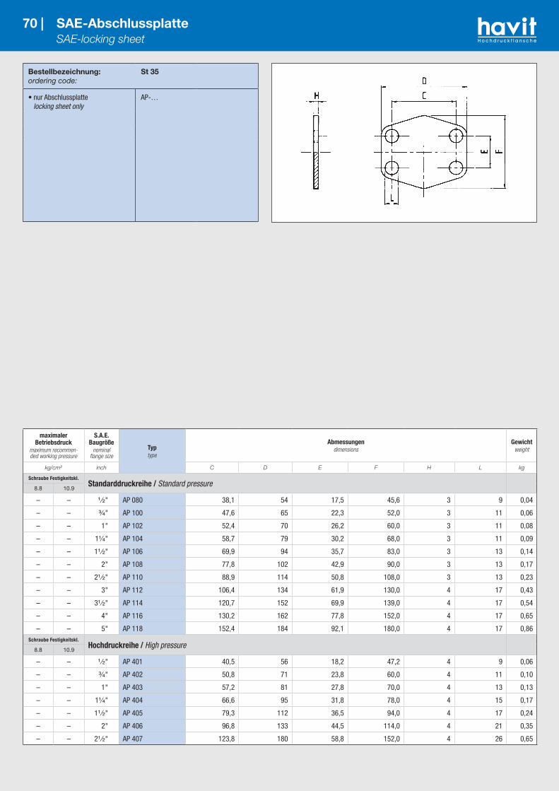
Bestellbezeichnung:ordering code:
St 35
• nur Abschlussplatte locking sheet only
AP-…
70 | SAE-Abschlussplatte SAE-locking sheet
maximaler Betriebsdruck
maximum recommen-ded working pressure
S.A.E. Baugröße
nominal flange size
Typtype
Abmessungendimensions
Gewichtweight
kg/cm² inch C D E F H L kg
Schraube Festigkeitskl.Standarddruckreihe / Standard pressure
8.8 10.9
– – ¹ ⁄₂" AP 080 38,1 54 17,5 45,6 3 9 0,04
– – ³⁄₄" AP 100 47,6 65 22,3 52,0 3 11 0,06
– – 1" AP 102 52,4 70 26,2 60,0 3 11 0,08
– – 1¹⁄₄" AP 104 58,7 79 30,2 68,0 3 11 0,09
– – 1¹ ⁄₂" AP 106 69,9 94 35,7 83,0 3 13 0,14
– – 2" AP 108 77,8 102 42,9 90,0 3 13 0,17
– – 2¹ ⁄₂" AP 110 88,9 114 50,8 108,0 3 13 0,23
– – 3" AP 112 106,4 134 61,9 130,0 4 17 0,43
– – 3¹ ⁄₂" AP 114 120,7 152 69,9 139,0 4 17 0,54
– – 4" AP 116 130,2 162 77,8 152,0 4 17 0,65
– – 5" AP 118 152,4 184 92,1 180,0 4 17 0,86Schraube Festigkeitskl.
Hochdruckreihe / High pressure8.8 10.9
– – ¹ ⁄₂" AP 401 40,5 56 18,2 47,2 4 9 0,06
– – ³⁄₄" AP 402 50,8 71 23,8 60,0 4 11 0,10
– – 1" AP 403 57,2 81 27,8 70,0 4 13 0,13
– – 1¹⁄₄" AP 404 66,6 95 31,8 78,0 4 15 0,17
– – 1¹ ⁄₂" AP 405 79,3 112 36,5 94,0 4 17 0,24
– – 2" AP 406 96,8 133 44,5 114,0 4 21 0,35
– – 2¹ ⁄₂" AP 407 123,8 180 58,8 152,0 4 26 0,65

Bestellbezeichnung:ordering code:
S235JRG2C45
• nur Abschlussplatte mit O-Ringnut locking sheet with o-ring groove only
APO-…
71 | SAE-Abschlussplatte mit O-Ringnut SAE-locking sheet with o-ringgroove
maximaler Betriebsdruck
maximum recommen-ded working pressure
S.A.E. Baugröße
nominal flange size
Typtype
Abmessungendimensions
Gewichtweight
kg/cm² inch C D E F H L kg
Schraube Festigkeitskl.Standarddruckreihe / Standard pressure
8.8 10.9
– – ¹ ⁄₂" APO-080 38,1 54 17,5 45,6 6 9 0,078
– – ³⁄₄" APO-100 47,6 65 22,3 50,0 6 11 0,106
– – 1" APO-102 52,4 70 26,2 60,0 6 11 0,138
– – 1¹⁄₄" APO-104 58,7 79 30,2 68,0 6 11 0,183
– – 1¹ ⁄₂" APO-106 69,9 94 35,7 82,0 6 13 0,265
– – 2" APO-108 77,8 102 42,9 76,0 6 13 0,302
– – 2¹ ⁄₂" APO-110 88,9 114 50,8 108,0 6 13 0,443
– – 3" APO-112 106,4 134 61,9 130,0 6 17 0,622
– – 3¹ ⁄₂" APO-114 120,7 152 69,9 139,0 6 17 0,776
– – 4" APO-116 130,2 162 77,8 152,0 6 17 0,912
– – 5" APO-118 152,4 184 92,1 180,0 6 17 1,238Schraube Festigkeitskl.
Hochdruckreihe / High pressure8.8 10.9
– – ¹ ⁄₂" APO-401 40,5 56 18,2 47,2 6 9 0,085
– – ³⁄₄" APO-402 50,8 71 23,8 60,0 6 11 0,141
– – 1" APO-403 57,2 81 27,8 70,0 6 13 0,187
– – 1¹⁄₄" APO-404 66,6 95 31,8 78,0 6 15 0,249
– – 1¹ ⁄₂" APO-405 79,3 112 36,5 94,0 6 17 0,357
– – 2" APO-406 96,8 133 44,5 114,0 6 21 0,510
– – 2¹ ⁄₂" APO-407 123,8 180 58,8 152,0 6 26 0,948
– – 3" APO-408 152,4 208 71,6 178,0 6 33 1,270
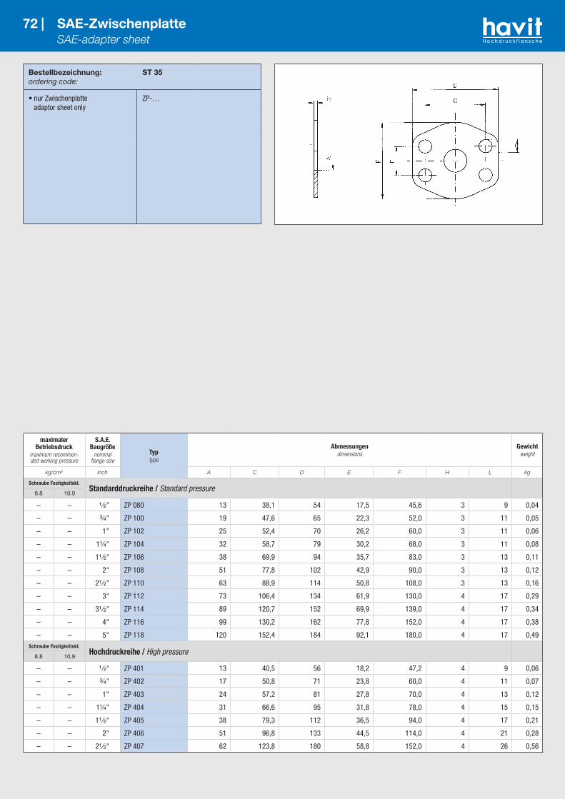
Bestellbezeichnung:ordering code:
ST 35
• nur Zwischenplatte adaptor sheet only
ZP-…
72 | SAE-Zwischenplatte SAE-adapter sheet
maximaler Betriebsdruck
maximum recommen-ded working pressure
S.A.E. Baugröße
nominal flange size
Typtype
Abmessungendimensions
Gewichtweight
kg/cm² inch A C D E F H L kg
Schraube Festigkeitskl.Standarddruckreihe / Standard pressure
8.8 10.9
– – ¹ ⁄₂" ZP 080 13 38,1 54 17,5 45,6 3 9 0,04
– – ³⁄₄" ZP 100 19 47,6 65 22,3 52,0 3 11 0,05
– – 1" ZP 102 25 52,4 70 26,2 60,0 3 11 0,06
– – 1¹⁄₄" ZP 104 32 58,7 79 30,2 68,0 3 11 0,08
– – 1¹ ⁄₂" ZP 106 38 69,9 94 35,7 83,0 3 13 0,11
– – 2" ZP 108 51 77,8 102 42,9 90,0 3 13 0,12
– – 2¹ ⁄₂" ZP 110 63 88,9 114 50,8 108,0 3 13 0,16
– – 3" ZP 112 73 106,4 134 61,9 130,0 4 17 0,29
– – 3¹ ⁄₂" ZP 114 89 120,7 152 69,9 139,0 4 17 0,34
– – 4" ZP 116 99 130,2 162 77,8 152,0 4 17 0,38
– – 5" ZP 118 120 152,4 184 92,1 180,0 4 17 0,49Schraube Festigkeitskl.
Hochdruckreihe / High pressure8.8 10.9
– – ¹ ⁄₂" ZP 401 13 40,5 56 18,2 47,2 4 9 0,06
– – ³⁄₄" ZP 402 17 50,8 71 23,8 60,0 4 11 0,07
– – 1" ZP 403 24 57,2 81 27,8 70,0 4 13 0,12
– – 1¹⁄₄" ZP 404 31 66,6 95 31,8 78,0 4 15 0,15
– – 1¹ ⁄₂" ZP 405 38 79,3 112 36,5 94,0 4 17 0,21
– – 2" ZP 406 51 96,8 133 44,5 114,0 4 21 0,28
– – 2¹ ⁄₂" ZP 407 62 123,8 180 58,8 152,0 4 26 0,56

Bestellbezeichnung:ordering code:
S355J2 *1
1.4404 *1
316L
• nur Flansch flange only
AFC-…G¹⁄₄” AFC-X-…G¹⁄₄”
• incl. metrischem Schraubensatz und O-Ring including metric bolts and o-ring
AFC-…G¹⁄₄”M AFC-X-…G¹⁄₄”MX
• incl. UNC-Schraubensatz und O-Ring including UNC bolts and o-ring
AFC-…G¹⁄₄”U AFC-X-…G¹⁄₄”UX
73 | SAE-Flansch mit Messanschluss – gerader Abgang SAE-flange with test point – straight
*1 oder vergleichbare Güte / or comparable material*2 L=13,5 für UNC-Schrauben / L=13.5 with UNC-bolts
maximaler Betriebsdruck
maximum recommen-ded working pressure
S.A.E. Baugröße
nominal flange size
Typtype
Abmessungendimensions
Schraubenbolts
Gewichtweight
kg/cm² inch C D E F H L M kg
Schraube Festigkeitskl.Standarddruckreihe / Standard pressure metr. unc.
8.8 10.9
350 350 ¹ ⁄₂" AFC 080 G¹⁄₄" 38,1 56 17,5 48 16 9,0 M 8x30 ⁵⁄₁₆ x 1¹⁄₄ 0,20
350 350 ³⁄₄" AFC 100 G¹⁄₄" 47,6 65 22,3 50 16 11,0 M 10x35 ³⁄₈ x 1¹ ⁄₂ 0,30
250 320 1" AFC 102 G¹⁄₄" 52,4 70 26,2 60 19 11,0 M 10x35 ³⁄₈ x 1¹ ⁄₂ 0,37
200 280 1¹⁄₄" AFC 104 G¹⁄₄" 58,7 79 30,2 68 18 11,5 M 10x40 ⁷⁄₁₆ x 1¹ ⁄₂ 0,54
200 210 1¹ ⁄₂" AFC 106 G¹⁄₄" 69,9 93 35,7 78 20 13,5 M 12x45 ¹ ⁄₂ x 1³⁄₄ 0,90
160 210 2" AFC 108 G¹⁄₄" 77,8 102 42,9 90 20 13,5 M 12x45 ¹ ⁄₂ x 1³⁄₄ 1,00
100 175 2¹ ⁄₂" AFC 110 G¹⁄₄" 88,9 114 50,8 105 20 13,5 M 12x45 ¹ ⁄₂ x 1³⁄₄ 1,35
100 160 3" AFC 112 G¹⁄₄" 106,4 134 61,9 124 24 17,5 M 16x50 ⁵⁄₈ x 2 2,35
35 35 3¹ ⁄₂" AFC 114 G¹⁄₄" 120,7 152 69,9 136 22 17,5 M 16x50 ⁵⁄₈ x 2 2,90
35 35 4" AFC 116 G¹⁄₄" 130,2 162 77,8 146 25 17,5 M 16x50 ⁵⁄₈ x 2 3,90
35 35 5" AFC 118 G¹⁄₄" 152,4 190 92,1 170 28 17,5 M 16x55 ⁵⁄₈ x 2 4,00Schraube Festigkeitskl.
Hochdruckreihe / High pressure metr. unc.8.8 10.9
350 420 ¹ ⁄₂" AFC 401 G¹⁄₄" 40,5 56 18,2 48 16 9,0 M 8x30 ⁵⁄₁₆ x 1¹⁄₄ 0,20
350 420 ³⁄₄" AFC 402 G¹⁄₄" 50,8 71 23,8 60 19 11,0 M 10x35 ³⁄₈ x 1¹ ⁄₂ 0,48
350 420 1" AFC 403 G¹⁄₄" 57,2 81 27,8 70 24 13,0 M 12x45 ⁷⁄₁₆ x 1¹ ⁄₂ 0,77
350 420 1¹⁄₄" AFC 404 G¹⁄₄" 66,6 95 31,8 78 27 15,0 *2 M 14x50 ¹ ⁄₂ x 1³⁄₄ 0,85
350 420 1¹ ⁄₂" AFC 405 G¹⁄₄" 79,3 112 36,5 94 30 17,0 M 16x50 ⁵⁄₈ x 2 1,80
350 420 2" AFC 406 G¹⁄₄" 96,8 134 44,5 114 28 21,0 M 20x65 ³⁄₄ x 2¹ ⁄₂ 2,00
350 420 2¹ ⁄₂" AFC 407 G¹⁄₄" 123,8 180 58,8 150 45 26,0 M 24x80 – 5,30
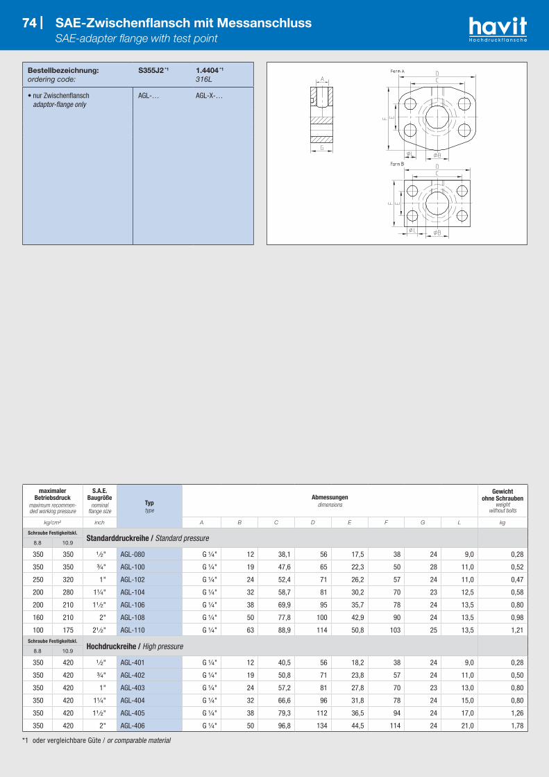
74 |
*1 oder vergleichbare Güte / or comparable material
74 | SAE-Zwischenflansch mit Messanschluss SAE-adapter flange with test point
maximaler Betriebsdruck
maximum recommen-ded working pressure
S.A.E. Baugröße
nominal flange size
Typtype
Abmessungendimensions
Gewicht ohne Schrauben
weight without bolts
kg/cm² inch A B C D E F G L kg
Schraube Festigkeitskl.Standarddruckreihe / Standard pressure
8.8 10.9
350 350 ¹ ⁄₂" AGL-080 G ¹⁄₄" 12 38,1 56 17,5 38 24 9,0 0,28
350 350 ³⁄₄" AGL-100 G ¹⁄₄" 19 47,6 65 22,3 50 28 11,0 0,52
250 320 1" AGL-102 G ¹⁄₄" 24 52,4 71 26,2 57 24 11,0 0,47
200 280 1¹⁄₄" AGL-104 G ¹⁄₄" 32 58,7 81 30,2 70 23 12,5 0,58
200 210 1¹ ⁄₂" AGL-106 G ¹⁄₄" 38 69,9 95 35,7 78 24 13,5 0,80
160 210 2" AGL-108 G ¹⁄₄" 50 77,8 100 42,9 90 24 13,5 0,98
100 175 2¹ ⁄₂" AGL-110 G ¹⁄₄" 63 88,9 114 50,8 103 25 13,5 1,21Schraube Festigkeitskl.
Hochdruckreihe / High pressure8.8 10.9
350 420 ¹ ⁄₂" AGL-401 G ¹⁄₄" 12 40,5 56 18,2 38 24 9,0 0,28
350 420 ³⁄₄" AGL-402 G ¹⁄₄" 19 50,8 71 23,8 57 24 11,0 0,50
350 420 1" AGL-403 G ¹⁄₄" 24 57,2 81 27,8 70 23 13,0 0,80
350 420 1¹⁄₄" AGL-404 G ¹⁄₄" 32 66,6 96 31,8 78 24 15,0 0,80
350 420 1¹ ⁄₂" AGL-405 G ¹⁄₄" 38 79,3 112 36,5 94 24 17,0 1,26
350 420 2" AGL-406 G ¹⁄₄" 50 96,8 134 44,5 114 24 21,0 1,78
Bestellbezeichnung:ordering code:
S355J2 *1
1.4404 *1
316L
• nur Zwischenflansch adaptor-flange only
AGL-… AGL-X-…

75 |
*1 oder vergleichbare Güte / or comparable material
75 | SAE-Zwischenflanschplatte SAE-connector flange
maximaler Betriebsdruck
maximum recommen-ded working pressure
S.A.E. Baugröße
nominal flange size
Typtype
Abmessungendimensions
Gewichtweight
kg/cm² inch B C D E F G M kg
Schraube Festigkeitskl.Standarddruckreihe / Standard pressure
8.8 10.9
350 350 ¹ ⁄₂" ZFG-080 13 38,1 55 17,5 50 35 M 8 0,62
350 350 ³⁄₄" ZFG-100 19 47,6 65 22,3 50 40 M 10 0,94
250 320 1" ZFG-102 25 52,4 70 26,2 60 45 M 10 1,33
200 280 1¹⁄₄" ZFG-104 32 58,7 80 30,2 70 50 M 10 1,60
200 210 1¹ ⁄₂" ZFG-106 38 69,9 95 35,7 80 50 M 12 2,20
160 210 2" ZFG-108 51 77,8 105 42,9 95 50 M 12 2,80Schraube Festigkeitskl.
Hochdruckreihe / High pressure8.8 10.9
350 420 ¹ ⁄₂" ZFG-401 13 40,5 55 18,2 50 35 M 8 0,62
350 420 ³⁄₄" ZFG-402 19 50,8 70 23,8 60 45 M 10 1,41
350 420 1" ZFG-403 25 57,2 80 27,8 70 50 M 12 1,64
350 420 1¹⁄₄" ZFG-404 32 66,6 95 31,8 80 50 M 14 2,90
350 420 1¹ ⁄₂" ZFG-405 38 79,3 115 36,5 95 60 M 16 4,30
350 420 2" ZFG-406 51 96,8 135 44,5 115 65 M 20 6,20
Bestellbezeichnung:ordering code:
S355J2 *1
C45
• nur Flanschzwischenlpatte connector flange only
ZFG-…

Bestellbezeichnung:ordering code:
StahlSteel
• nur Zwischenstück elbow only
AG-…
76 | SAE-90° Adapter – geschweißt SAE-90° adapter – welded
maximaler Betriebsdruck
maximum recommen-ded working pressure
S.A.E. Baugröße
nominal flange size
Typtype
Abmessungendimensions
Gewichtweight
kg/cm² inch A1 A2 S1 S2 kg
Schraube Festigkeitskl.Standarddruckreihe / Standard pressure
8.8 10.9
350 350 ¹ ⁄₂" AG 3001 90° 30,2 30,2 70 70 0,65
350 350 ³⁄₄" AG 3002 90° 38,1 38,1 80 80 0,90
250 320 1" AG 3003 90° 44,4 44,4 90 90 1,15
200 280 1¹⁄₄" AG 3004 90° 50,8 50,8 103 103 1,50
200 210 1¹ ⁄₂" AG 3005 90° 60,3 60,3 115 115 2,55
160 210 2" AG 3006 90° 71,4 71,4 135 135 2,79
100 175 2¹ ⁄₂" AG 3007 90° 84,1 84,1 155 155 3,20
35 35 3" AG 3008 90° 101,6 101,6 175 175 4,60
35 35 3¹ ⁄₂" AG 3009 90° 114,3 114,3 175 175 5,12
35 35 4" AG 3010 90° 127,0 127,0 215 215 6,25
35 35 5" AG 3011 90° 152,4 152,4 250 250 7,65

77 |
Bestellbezeichnung:ordering code:
S355J2G3 1
1.4404 1
316L
• nur Flansch flange only
GFG-…M/…
Bestellbezeichnung:ordering code:
StahlSteel
• nur Zwischenstück elbow only
AG-…
77 | SAE-45° Adapter – geschweißt SAE-45° adapter – welded
maximaler Betriebsdruck
maximum recommen-ded working pressure
S.A.E. Baugröße
nominal flange size
Typtype
Abmessungendimensions
Gewichtweight
kg/cm² inch A1 A2 S1 S2 S3 R kg
Schraube Festigkeitskl.Standarddruckreihe / Standard pressure
8.8 10.9
350 350 ¹ ⁄₂" AG 3001 45° 30,2 30,2 72,7 30,1 31 28 0,47
350 350 ³⁄₄" AG 3002 45° 38,1 38,1 78,5 32,5 34 29 0,72
250 320 1" AG 3003 45° 44,5 44,5 88,3 36,6 36 38 0,99
200 280 1¹⁄₄" AG 3004 45° 50,8 50,8 95,4 39,5 36 48 1,37
200 210 1¹ ⁄₂" AG 3005 45° 60,3 60,3 103,5 42,9 37 57 1,81
160 210 2" AG 3006 45° 71,4 71,4 117,0 48,0 37 76 2,25
100 175 2¹ ⁄₂" AG 3007 45° 84,1 84,1 152,5 63,2 50 95 3,92
100 160 3" AG 3008 45° 101,6 101,6 171,1 70,9 53 114 6,07
35 35 3¹ ⁄₂" AG 3009 45° 114,3 114,3 148,9 61,7 40 114 6,04
35 35 4" AG 3010 45° 127,0 127,0 187,7 77,8 47 152 8,48
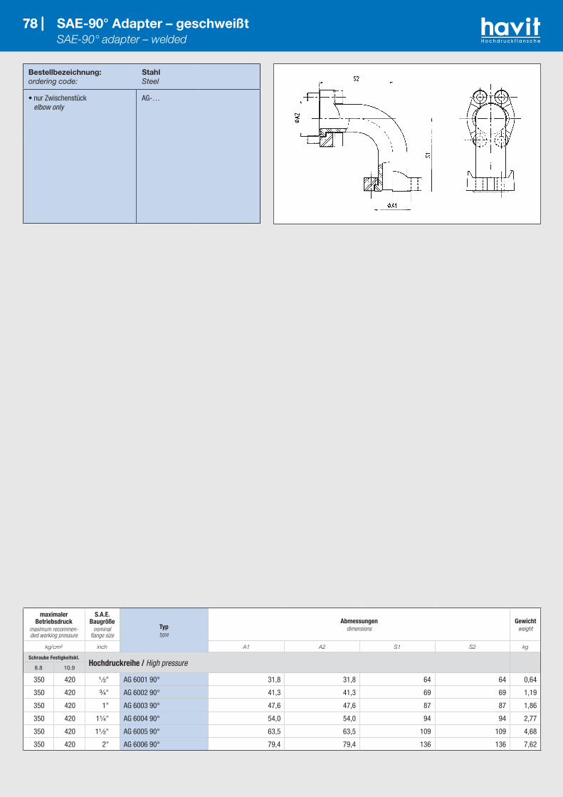
78 |
Bestellbezeichnung:ordering code:
S355J2G3 1
1.4404 1
316L
• nur Flansch flange only
GFG-…M/…
Bestellbezeichnung:ordering code:
StahlSteel
• nur Zwischenstück elbow only
AG-…
78 | SAE-90° Adapter – geschweißt SAE-90° adapter – welded
maximaler Betriebsdruck
maximum recommen-ded working pressure
S.A.E. Baugröße
nominal flange size
Typtype
Abmessungendimensions
Gewichtweight
kg/cm² inch A1 A2 S1 S2 kg
Schraube Festigkeitskl.Hochdruckreihe / High pressure
8.8 10.9
350 420 ¹ ⁄₂" AG 6001 90° 31,8 31,8 64 64 0,64
350 420 ³⁄₄" AG 6002 90° 41,3 41,3 69 69 1,19
350 420 1" AG 6003 90° 47,6 47,6 87 87 1,86
350 420 1¹⁄₄" AG 6004 90° 54,0 54,0 94 94 2,77
350 420 1¹ ⁄₂" AG 6005 90° 63,5 63,5 109 109 4,68
350 420 2" AG 6006 90° 79,4 79,4 136 136 7,62

Bestellbezeichnung:ordering code:
StahlSteel
• nur Zwischenstück elbow only
AG-…
79 | SAE-45° Adapter – geschweißt SAE-45° adapter – welded
maximaler Betriebsdruck
maximum recommen-ded working pressure
S.A.E. Baugröße
nominal flange size
Typtype
Abmessungendimensions
Gewichtweight
kg/cm² inch A1 A2 S1 S2 S3 R kg
Schraube Festigkeitskl.Hochdruckreihe / High pressure
8.8 10.9
350 420 ¹ ⁄₂" AG 6001 45° 31,8 31,8 81,3 33,7 36 28 0,59
350 420 ³⁄₄" AG 6002 45° 41,3 41,3 88,5 36,8 40 29 1,12
350 420 1" AG 6003 45° 47,6 47,6 98,6 40,8 42 38 1,75
350 420 1¹⁄₄" AG 6004 45° 54,0 54,0 114,2 47,3 47 48 2,56
350 420 1¹ ⁄₂" AG 6005 45° 63,5 63,5 129,1 53,5 52 57 4,39
350 420 2" AG 6006 45° 79,4 79,4 156,2 64,7 60 76 7,16

*1 oder vergleichbare Güte / or comparable material Wichtig: Alle Anschlüsse A, B und C können wahlweise mit O-Ringnut (Type A) oder ohne O-Ring (Type G) geliefert werden! / Important: All connections A, B und C can be supplied as requested with o-ring groove (type A) or without o-ring groove (type G)!
Bestellbezeichnung:ordering code:
StahlSteel
• nur T-Stück T-connection only
T-…
80 | SAE-T-Verbinder – geschweißt SAE-T-connection – welded
maximaler Betriebsdruck
maximum recommen-ded working pressure
Typtype
Anschluss Aconnection A
Anschluss Bconnection B
Anschluss Cconnection C
Gewichtweight
kg/cm² size A1 M size A2 size A3 G S kg
Schraube Festigkeitskl.Standarddruckreihe / Standard pressure
8.8 10.9
350 350 T 301 A-301 G-301 G ¹ ⁄₂" 30,2 M 8x30 ¹ ⁄₂" 30,2 ¹ ⁄₂" 30,2 133 67 0,97
350 350 T 302 A-302 G-302 G ³⁄₄" 38,1 M 10x35 ³⁄₄" 38,1 ³⁄₄" 38,1 160 80 1,20
350 350 T 302 A-302 G-301 G ³⁄₄" 38,1 M 10x35 ³⁄₄" 38,1 ¹ ⁄₂" 30,2 160 67 1,14
250 320 T 303 A-303 G-303 G 1" 44,4 M 10x35 1" 44,4 1" 44,4 177 88 1,63
250 320 T 303 A-303 G-302 G 1" 44,4 M 10x35 1" 44,4 ³⁄₄" 38,1 177 80 1,50
250 320 T 303 A-303 G-301 G 1" 44,4 M 10x35 1" 44,4 ¹ ⁄₂" 30,2 177 67 1,39
200 280 T 304 A-304 G-304 G 1¹⁄₄" 50,8 M 10x30 1¹⁄₄" 50,8 1¹⁄₄" 50,8 208 103 2,25
200 280 T 304 A-304 G-303 G 1¹⁄₄" 50,8 M 10x30 1¹⁄₄" 50,8 1" 44,4 208 88 2,05
200 280 T 304 A-304 G-302 G 1¹⁄₄" 50,8 M 10x30 1¹⁄₄" 50,8 ³⁄₄" 38,1 208 80 1,94
200 210 T 305 A-305 G-305 G 1¹ ⁄₂" 60,3 M 12x35 1¹ ⁄₂" 60,3 1¹ ⁄₂" 60,3 230 115 3,50
200 210 T 305 A-305 G-304 G 1¹ ⁄₂" 60,3 M 12x35 1¹ ⁄₂" 60,3 1¹⁄₄" 50,8 230 103 3,03
200 210 T 305 A-305 G-303 G 1¹ ⁄₂" 60,3 M 12x35 1¹ ⁄₂" 60,3 1" 44,4 230 88 2,94
160 210 T 306 A-306 G-306 G 2" 71,4 M 12x35 2" 71,4 2" 71,4 244 122 4,20
160 210 T 306 A-306 G-305 G 2" 71,4 M 12x35 2" 71,4 1¹ ⁄₂" 60,3 244 118 4,05
160 210 T 306 A-306 G-304 G 2" 71,4 M 12x35 2" 71,4 1¹⁄₄" 50,8 244 115 3,87
100 175 T 307 A-307 G-307 G 2¹ ⁄₂" 84,1 M 12x40 2¹ ⁄₂" 84,1 2¹ ⁄₂" 84,1 270 135 4,70
100 175 T 307 A-307 G-306 G 2¹ ⁄₂" 84,1 M 12x40 2¹ ⁄₂" 84,1 2" 74,1 270 128 4,30
100 175 T 307 A-307 G-305 G 2¹ ⁄₂" 84,1 M 12x40 2¹ ⁄₂" 84,1 1¹ ⁄₂" 60,3 270 125 4,10
100 138 T 308 A-308 G-308 G 3" 101,6 M 16x50 3" 101,6 3" 101,6 293 146 8,20
100 138 T 308 A-308 G-307 G 3" 101,6 M 16x50 3" 101,6 2¹ ⁄₂" 84,1 293 141 7,50
100 138 T 308 A-308 G-306 G 3" 101,6 M 16x50 3" 101,6 2" 71,4 293 133 7,20
35 35 T 309 A-309 G-309 G 3¹ ⁄₂" 114,3 M 16x50 3¹ ⁄₂" 114,3 3¹ ⁄₂" 114,3 293 146 9,55
35 35 T 309 A-309 G-308 G 3¹ ⁄₂" 114,3 M 16x50 3¹ ⁄₂" 114,3 3" 101,6 293 146 9,20
35 35 T 309 A-309 G-307 G 3¹ ⁄₂" 114,3 M 16x50 3¹ ⁄₂" 114,3 2¹ ⁄₂" 84,1 293 146 8,50
35 35 T 310 A-310 G-310 G 4" 127,0 M 16x50 4" 127,0 4" 127,0 332 165 12,10
35 35 T 310 A-310 G-309 G 4" 127,0 M 16x50 4" 127,0 3¹ ⁄₂" 114,3 332 158 11,60
35 35 T 310 A-310 G-308 G 4" 127,0 M 16x50 4" 127,0 3" 101,6 332 158 10,95
35 35 T 311 A-311 G-311 G 5" 152,4 M 16x55 5" 152,4 5" 152,4 370 185 14,70
35 35 T 311 A-311 G-310 G 5" 152,4 M 16x55 5" 152,4 4" 127,0 370 177 13,95
35 35 T 311 A-311 G-309 G 5" 152,4 M 16x55 5" 152,4 3¹ ⁄₂" 114,3 370 170 13,10
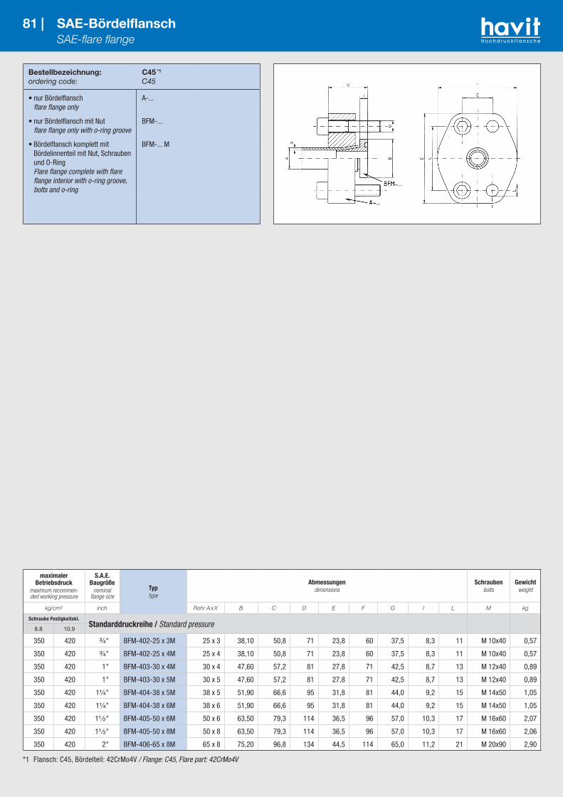
*1 Flansch: C45, Bördelteil: 42CrMo4V / Flange: C45, Flare part: 42CrMo4V
Bestellbezeichnung:ordering code:
C45 *1
C45
• nur Bördelflansch flare flange only
A-...
• nur Bördelflansch mit Nut flare flange only with o-ring groove
BFM-...
• Bördelflansch komplett mit Bördelinnenteil mit Nut, Schrauben und O-Ring Flare flange complete with flare flange interior with o-ring groove, bolts and o-ring
BFM-... M
81 | SAE-Bördelflansch SAE-flare flange
maximaler Betriebsdruck
maximum recommen-ded working pressure
S.A.E. Baugröße
nominal flange size
Typtype
Abmessungendimensions
Schraubenbolts
Gewichtweight
kg/cm² inch Rohr A x X B C D E F G I L M kg
Schraube Festigkeitskl.Standarddruckreihe / Standard pressure
8.8 10.9
350 420 ³⁄₄" BFM-402-25 x 3M 25 x 3 38,10 50,8 71 23,8 60 37,5 8,3 11 M 10x40 0,57
350 420 ³⁄₄" BFM-402-25 x 4M 25 x 4 38,10 50,8 71 23,8 60 37,5 8,3 11 M 10x40 0,57
350 420 1" BFM-403-30 x 4M 30 x 4 47,60 57,2 81 27,8 71 42,5 8,7 13 M 12x40 0,89
350 420 1" BFM-403-30 x 5M 30 x 5 47,60 57,2 81 27,8 71 42,5 8,7 13 M 12x40 0,89
350 420 1¹⁄₄" BFM-404-38 x 5M 38 x 5 51,90 66,6 95 31,8 81 44,0 9,2 15 M 14x50 1,05
350 420 1¹⁄₄" BFM-404-38 x 6M 38 x 6 51,90 66,6 95 31,8 81 44,0 9,2 15 M 14x50 1,05
350 420 1¹ ⁄₂" BFM-405-50 x 6M 50 x 6 63,50 79,3 114 36,5 96 57,0 10,3 17 M 16x60 2,07
350 420 1¹ ⁄₂" BFM-405-50 x 8M 50 x 8 63,50 79,3 114 36,5 96 57,0 10,3 17 M 16x60 2,06
350 420 2" BFM-406-65 x 8M 65 x 8 75,20 96,8 134 44,5 114 65,0 11,2 21 M 20x90 2,90

*1 Flansch: C45, Bördelteil: 42CrMo4V / Flange: C45, Flare part: 42CrMo4V
Bestellbezeichnung:ordering code:
C45 *1
C45
• Flanschkupplung komplett flange-coupling
BFK-…-M
82 | SAE-Bördelflanschkupplung SAE-flare flange-coupling
maximaler Betriebsdruck
maximum recommen-ded working pressure
S.A.E. Baugröße
nominal flange size
Typtype
Abmessungendimensions
Schraubenbolts
Gewichtweight
kg/cm² inch Rohr A x X C D E F G I L M kg
Schraube Festigkeitskl.Hochdruckreihe / High pressure
8.8 10.9
350 420 ³⁄₄" BFK-402-25 x 3M 25 x 3 50,8 71 23,8 60 75 16,5 11 M 10x60 1,14
350 420 ³⁄₄" BFK-402-25 x 4M 25 x 4 50,8 71 23,8 60 75 16,5 11 M 10x60 1,14
350 420 1" BFK-403-30 x 4M 30 x 4 57,2 81 27,8 71 85 17,4 13 M 12x70 1,78
350 420 1" BFK-403-30 x 5M 30 x 5 57,2 81 27,8 71 85 17,4 13 M 12x70 1,78
350 420 1¹⁄₄" BFK-404-38 x 5M 38 x 5 66,6 95 31,8 81 88 18,4 15 M 14x80 2,10
350 420 1¹⁄₄" BFK-404-38 x 6M 38 x 6 66,6 95 31,8 81 88 18,4 15 M 14x80 2,10
350 420 1¹ ⁄₂" BFK-405-50 x 6M 50 x 6 79,3 114 36,5 96 114 20,6 17 M 16x90 4,14
350 420 1¹ ⁄₂" BFK-405-50 x 8M 50 x 8 79,3 114 36,5 96 114 20,6 17 M 16x90 4,10
350 420 2" BFK-406-65 x 8M 65 x 8 96,8 134 44,5 114 130 22,4 21 M 20x120 5,80

*1 oder vergleichbare Güte / or comparable material
Bestellbezeichnung:ordering code:
S355J2 *1 1.4404 *1
316L
• nur Reduzierflansch flange only
G-AF-… G-AF-X…
83 | SAE-Reduzierflansch – gerade SAE-adapter flange – straight
maximaler Betriebsdruck
maximum recommen-ded working pressure
S.A.E. Baugrößenominal flange size Typ
type
Abmessungendimensions
Schraubenbolts
Gewichtweight
kg/cm² inch B1/B C1 C2 D E1 E2 F H L M kg
Schraube Festigkeitskl.Standarddruckreihe / Standard pressure metr. unc.
8.8 10.9
250 320 1" - ³⁄₄" G-AF-303-302 25/19 52,4 47,6 70 26,2 22,3 65 30 11,0 M 10 M 10x30 – 0,78
200 280 1¹⁄₄" - 1" G-AF-304-303 32/25 58,7 52,4 80 30,2 26,2 70 30 11,0 M 10 M 10x30 – 1,00
200 210 1¹ ⁄₂" - 1¹⁄₄" G-AF-305-304 38/32 69,9 58,7 95 35,7 30,2 80 30 13,5 M 10 M 12x35 – 1,32
160 160 2" - 1¹ ⁄₂" G-AF-306-305 46/38 77,8 69,9 120 42,9 35,7 95 30 13,5 M 12 M 12x35 – 1,64
160 160 2" - 1¹⁄₄" G-AF-306-304 51/32 77,8 58,7 102 42,9 30,2 80 35 13,5 M 10 M 12x40 – 1,60
100 175 2¹ ⁄₂" - 2" G-AF-307-306 64/51 88,9 77,8 114 50,8 42,9 109 35 13,5 M 12 M 12x40 – 2,47
100 175 2¹ ⁄₂" - 1¹ ⁄₂" G-AF-307-305 62/38 88,9 69,9 114 50,8 35,7 109 35 13,5 M 12 M 12x40 – 2,61
100 160 3" - 2" G-AF-308-306 76/51 106,4 77,8 140 61,9 42,9 114 40 17,5 M 12 M 16x50 – 3,52
100 160 3" - 2¹ ⁄₂" G-AF-308-307 76/64 106,4 88,9 140 61,9 50,8 114 40 17,5 M 12 M 16x50 – 3,30
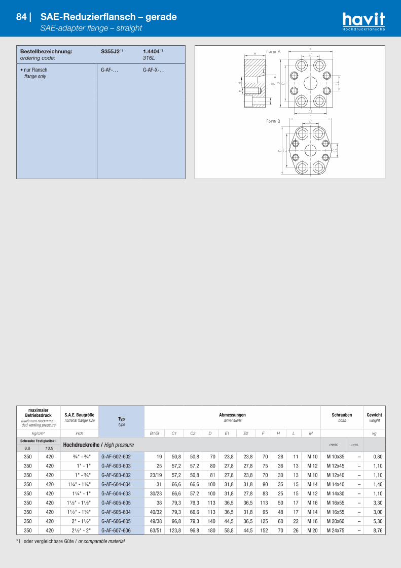
*1 oder vergleichbare Güte / or comparable material
Bestellbezeichnung:ordering code:
S355J2 *1 1.4404 *1
316L
• nur Flansch flange only
G-AF-… G-AF-X-…
84 | SAE-Reduzierflansch – gerade SAE-adapter flange – straight
maximaler Betriebsdruck
maximum recommen-ded working pressure
S.A.E. Baugrößenominal flange size Typ
type
Abmessungendimensions
Schraubenbolts
Gewichtweight
kg/cm² inch B1/B C1 C2 D E1 E2 F H L M kg
Schraube Festigkeitskl.Hochdruckreihe / High pressure metr. unc.
8.8 10.9
350 420 ³⁄₄" - ³⁄₄" G-AF-602-602 19 50,8 50,8 70 23,8 23,8 70 28 11 M 10 M 10x35 – 0,80
350 420 1" - 1" G-AF-603-603 25 57,2 57,2 80 27,8 27,8 75 36 13 M 12 M 12x45 – 1,10
350 420 1" - ³⁄₄" G-AF-603-602 23/19 57,2 50,8 81 27,8 23,8 70 30 13 M 10 M 12x40 – 1,10
350 420 1¹⁄₄" - 1¹⁄₄" G-AF-604-604 31 66,6 66,6 100 31,8 31,8 90 35 15 M 14 M 14x40 – 1,40
350 420 1¹⁄₄" - 1" G-AF-604-603 30/23 66,6 57,2 100 31,8 27,8 83 25 15 M 12 M 14x30 – 1,10
350 420 1¹ ⁄₂" - 1¹ ⁄₂" G-AF-605-605 38 79,3 79,3 113 36,5 36,5 113 50 17 M 16 M 16x55 – 3,30
350 420 1¹ ⁄₂" - 1¹⁄₄" G-AF-605-604 40/32 79,3 66,6 113 36,5 31,8 95 48 17 M 14 M 16x55 – 3,00
350 420 2" - 1¹ ⁄₂" G-AF-606-605 49/38 96,8 79,3 140 44,5 36,5 125 60 22 M 16 M 20x60 – 5,30
350 420 2¹ ⁄₂" - 2" G-AF-607-606 63/51 123,8 96,8 180 58,8 44,5 152 70 26 M 20 M 24x75 – 8,76
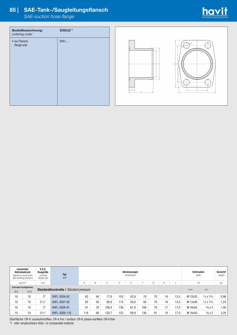
Oberfläche: CR-6: auslaufend/Neu: CR-6 frei / surface: CR-6: phase-out/New: CR-6 free*1 oder vergleichbare Güte / or comparable material
Bestellbezeichnung:ordering code:
S355J2 *1
• nur Flansch flange only
SHFL-…
85 | SAE-Tank-/Saugleitungsflansch SAE-suction hose flange
maximaler Betriebsdruck
maximum recommen-ded working pressure
S.A.E. Baugröße
nominal flange size
Typtype
Abmessungendimensions
Schraubenbolts
Gewichtweight
kg/cm² inch A B C D E F G H L M kg
Schraube Festigkeitskl.Standarddruckreihe / Standard pressure metr. unc.
8.8 10.9
10 10 2" SHFL-3006-62 62 48 77,8 103 42,9 70 70 16 13,5 M 12x35 ¹ ⁄₂ x 1³⁄₄ 0,96
10 10 2¹ ⁄₂" SHFL-3007-62 62 50 88,9 114 50,8 84 70 19 13,5 M 12x40 ¹ ⁄₂ x 1³⁄₄ 1,24
10 10 3" SHFL-3008-91 91 78 106,4 138 61,9 108 70 17 17,0 M 16x50 ⁵⁄₈ x 2 1,58
10 10 3¹ ⁄₂" SHFL-3009-116 116 89 120,7 152 69,9 136 91 18 17,0 M 16x50 ⁵⁄₈ x 2 3,29
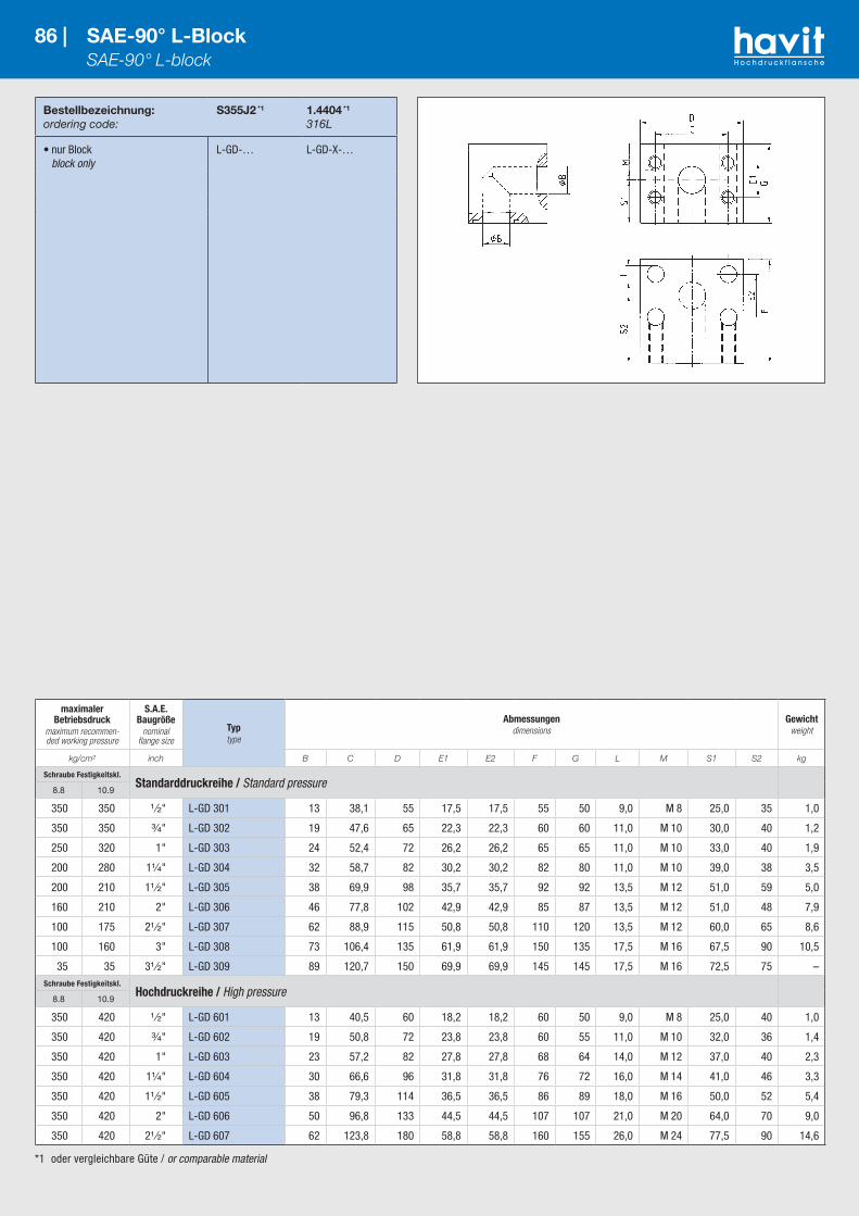
*1 oder vergleichbare Güte / or comparable material
Bestellbezeichnung:ordering code:
S355J2 *1 1.4404 *1
316L
• nur Block block only
L-GD-… L-GD-X-…
86 | SAE-90° L-Block SAE-90° L-block
maximaler Betriebsdruck
maximum recommen-ded working pressure
S.A.E. Baugröße
nominal flange size
Typtype
Abmessungendimensions
Gewichtweight
kg/cm² inch B C D E1 E2 F G L M S1 S2 kg
Schraube Festigkeitskl.Standarddruckreihe / Standard pressure
8.8 10.9
350 350 ¹ ⁄₂" L-GD 301 13 38,1 55 17,5 17,5 55 50 9,0 M 8 25,0 35 1,0
350 350 ³⁄₄" L-GD 302 19 47,6 65 22,3 22,3 60 60 11,0 M 10 30,0 40 1,2
250 320 1" L-GD 303 24 52,4 72 26,2 26,2 65 65 11,0 M 10 33,0 40 1,9
200 280 1¹⁄₄" L-GD 304 32 58,7 82 30,2 30,2 82 80 11,0 M 10 39,0 38 3,5
200 210 1¹ ⁄₂" L-GD 305 38 69,9 98 35,7 35,7 92 92 13,5 M 12 51,0 59 5,0
160 210 2" L-GD 306 46 77,8 102 42,9 42,9 85 87 13,5 M 12 51,0 48 7,9
100 175 2¹ ⁄₂" L-GD 307 62 88,9 115 50,8 50,8 110 120 13,5 M 12 60,0 65 8,6
100 160 3" L-GD 308 73 106,4 135 61,9 61,9 150 135 17,5 M 16 67,5 90 10,5
35 35 3¹ ⁄₂" L-GD 309 89 120,7 150 69,9 69,9 145 145 17,5 M 16 72,5 75 –Schraube Festigkeitskl.
Hochdruckreihe / High pressure8.8 10.9
350 420 ¹ ⁄₂" L-GD 601 13 40,5 60 18,2 18,2 60 50 9,0 M 8 25,0 40 1,0
350 420 ³⁄₄" L-GD 602 19 50,8 72 23,8 23,8 60 55 11,0 M 10 32,0 36 1,4
350 420 1" L-GD 603 23 57,2 82 27,8 27,8 68 64 14,0 M 12 37,0 40 2,3
350 420 1¹⁄₄" L-GD 604 30 66,6 96 31,8 31,8 76 72 16,0 M 14 41,0 46 3,3
350 420 1¹ ⁄₂" L-GD 605 38 79,3 114 36,5 36,5 86 89 18,0 M 16 50,0 52 5,4
350 420 2" L-GD 606 50 96,8 133 44,5 44,5 107 107 21,0 M 20 64,0 70 9,0
350 420 2¹ ⁄₂" L-GD 607 62 123,8 180 58,8 58,8 160 155 26,0 M 24 77,5 90 14,6
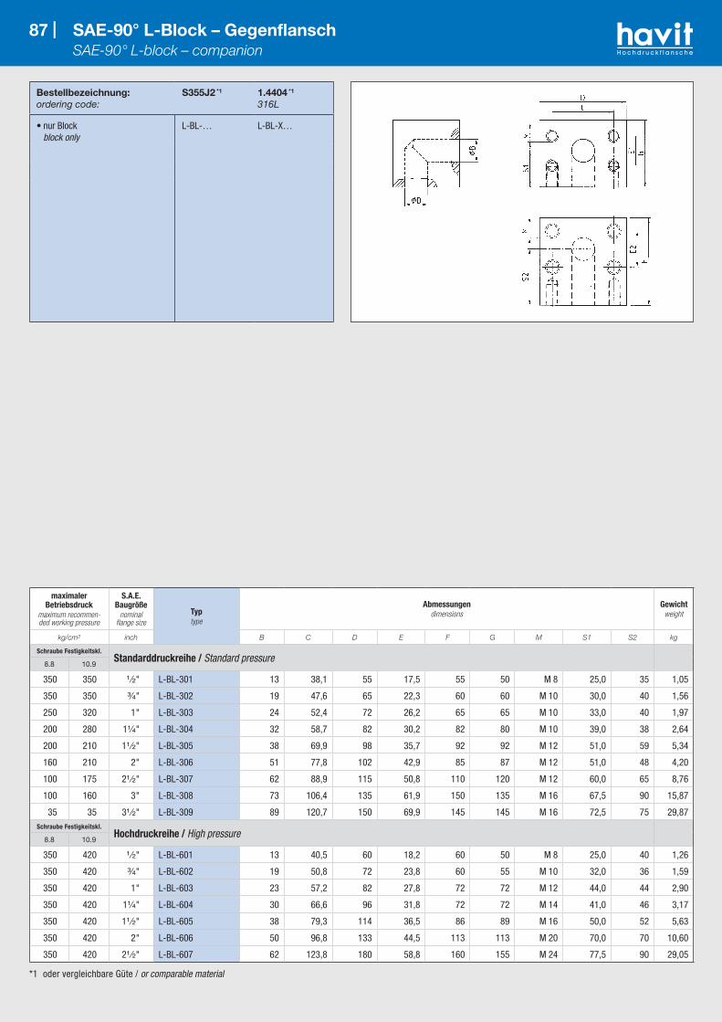
*1 oder vergleichbare Güte / or comparable material
Bestellbezeichnung:ordering code:
S355J2 *1 1.4404 *1
316L
• nur Block block only
L-BL-… L-BL-X…
87 | SAE-90° L-Block – Gegenflansch SAE-90° L-block – companion
maximaler Betriebsdruck
maximum recommen-ded working pressure
S.A.E. Baugröße
nominal flange size
Typtype
Abmessungendimensions
Gewichtweight
kg/cm² inch B C D E F G M S1 S2 kg
Schraube Festigkeitskl.Standarddruckreihe / Standard pressure
8.8 10.9
350 350 ¹ ⁄₂" L-BL-301 13 38,1 55 17,5 55 50 M 8 25,0 35 1,05
350 350 ³⁄₄" L-BL-302 19 47,6 65 22,3 60 60 M 10 30,0 40 1,56
250 320 1" L-BL-303 24 52,4 72 26,2 65 65 M 10 33,0 40 1,97
200 280 1¹⁄₄" L-BL-304 32 58,7 82 30,2 82 80 M 10 39,0 38 2,64
200 210 1¹ ⁄₂" L-BL-305 38 69,9 98 35,7 92 92 M 12 51,0 59 5,34
160 210 2" L-BL-306 51 77,8 102 42,9 85 87 M 12 51,0 48 4,20
100 175 2¹ ⁄₂" L-BL-307 62 88,9 115 50,8 110 120 M 12 60,0 65 8,76
100 160 3" L-BL-308 73 106,4 135 61,9 150 135 M 16 67,5 90 15,87
35 35 3¹ ⁄₂" L-BL-309 89 120,7 150 69,9 145 145 M 16 72,5 75 29,87Schraube Festigkeitskl.
Hochdruckreihe / High pressure8.8 10.9
350 420 ¹ ⁄₂" L-BL-601 13 40,5 60 18,2 60 50 M 8 25,0 40 1,26
350 420 ³⁄₄" L-BL-602 19 50,8 72 23,8 60 55 M 10 32,0 36 1,59
350 420 1" L-BL-603 23 57,2 82 27,8 72 72 M 12 44,0 44 2,90
350 420 1¹⁄₄" L-BL-604 30 66,6 96 31,8 72 72 M 14 41,0 46 3,17
350 420 1¹ ⁄₂" L-BL-605 38 79,3 114 36,5 86 89 M 16 50,0 52 5,63
350 420 2" L-BL-606 50 96,8 133 44,5 113 113 M 20 70,0 70 10,60
350 420 2¹ ⁄₂" L-BL-607 62 123,8 180 58,8 160 155 M 24 77,5 90 29,05

*1 oder vergleichbare Güte / or comparable material
Bestellbezeichnung:ordering code:
S355J2 *1 1.4404 *1
316L
• nur Block block only
RED-GD-… RED-GD-X-…
88 | SAE-90° L-Reduzierblock SAE-90° L-reduction
maximaler Betriebsdruck
maximum recommen-ded working pressure
S.A.E. Baugrößenominal flange size Typ
type
Abmessungendimensions
Gewichtweight
kg/cm² inch B1 B2 C1 C2 D E1 E2 F G L M S1 S2 kg
Schraube Festigkeitskl.Hochdruckreihe / High pressure
8.8 10.9
350 420 1" - ³⁄₄" RED-GD 603-602 23 19 57,2 50,8 82 27,8 23,8 68 64 14 M 10 37 40 2,2
350 420 1¹⁄₄" - ³⁄₄" RED-GD 604-602 30 19 66,6 50,8 96 31,8 23,8 76 72 16 M 10 41 46 3,6
350 420 1¹⁄₄" - 1" RED-GD 604-603 30 23 66,6 57,2 96 31,8 27,8 76 72 16 M 12 41 46 3,3
350 420 1¹ ⁄₂" - 1¹⁄₄" RED-GD 605-604 38 30 79,3 66,6 114 36,5 31,8 86 89 19 M 14 50 52 5,7
350 420 2" - 1¹ ⁄₂" RED-GD 606-605 50 38 96,8 79,3 133 44,5 36,5 110 110 21 M 16 64 70 9,0

*1 oder vergleichbare Güte / or comparable material
Bestellbezeichnung:ordering code:
S355J2 *1 1.4404 *1
316L
• nur Block block only
T-GD-… T-GD-X…
89 | SAE-T-Block SAE-T-block
maximaler Betriebsdruck
maximum recommen-ded working pressure
S.A.E. Baugröße
nominal flange size
Typtype
Abmessungendimensions
Gewichtweight
kg/cm² inch B C D E1 E2 F G L M S1 S2 kg
Schraube Festigkeitskl.Hochdruckreihe / High pressure
8.8 10.9
350 420 ³⁄₄" T-GD 602-602 19 50,8 72 23,8 23,8 72 55 11 M 10 32 36,0 1,7
350 420 1" T-GD 603-603 23 57,2 82 27,8 27,8 90 64 14 M 12 37 45,0 2,9
350 420 1¹⁄₄" T-GD 604-604 30 66,6 96 31,8 31,8 100 72 16 M 14 41 50,0 3,8
350 420 1¹ ⁄₂" T-GD 605-605 38 79,3 114 36,5 36,5 107 89 18 M 16 50 55,0 8,9
350 420 2" T-GD 606-606 50 96,8 133 44,5 44,5 135 107 22 M 20 64 67,5 12,7

*1 oder vergleichbare Güte / or comparable material
Bestellbezeichnung:ordering code:
S355J2 *1 1.4404 *1
316L
• nur Block block only
T-BL-… T-BL-X…
90 | SAE-T-Block – Gegenflanschausführung SAE-T-Block – companion
maximaler Betriebsdruck
maximum recommen-ded working pressure
S.A.E. Baugröße
nominal flange size
Typtype
Abmessungendimensions
Gewichtweight
kg/cm² inch B C D E1 E2 F G S1 M kg
Schraube Festigkeitskl.Standarddruckreihe / Standard pressure
8.8 10.9
350 350 ¹ ⁄₂" T-BL-301-301 13 38,1 55 17,5 17,5 70 50 25,0 M 8 1,4
350 350 ³⁄₄" T-BL-302-302 19 47,6 65 22,3 22,3 75 55 27,5 M 10 1,8
250 320 1" T-BL-303-303 25 52,4 70 26,2 26,2 80 60 30,0 M 10 2,3
200 280 1¹⁄₄" T-BL-304-304 32 58,7 80 30,2 30,2 90 70 35,0 M 10 3,9
200 210 1¹ ⁄₂" T-BL-305-305 38 69,9 95 35,7 35,7 110 85 42,5 M 12 6,3
160 210 2" T-BL-306-306 50 77,8 110 42,9 42,9 120 100 50,0 M 12 8,3
100 175 2¹ ⁄₂" T-BL-307-307 63 88,9 110 50,8 50,8 160 120 60,0 M 12 11,6
100 160 3" T-BL-308-308 73 106,4 135 61,9 61,9 160 160 80,0 M 16 15,3
35 35 3¹ ⁄₂" T-BL-309-309 89 120,7 150 69,9 69,9 160 145 72,5 M 16 16,2Schraube Festigkeitskl.
Hochdruckreihe / High pressure8.8 10.9
350 420 ¹ ⁄₂" T-BL-601-601 13 40,5 60 18,2 18,2 90 50 25,0 M 8 1,3
350 420 ³⁄₄" T-BL-602-602 19 50,8 70 23,8 23,8 72 55 32,0 M 10 1,7
350 420 1" T-BL-603-603 23 57,2 82 27,8 27,8 90 64 37,0 M 12 2,9
350 420 1¹⁄₄" T-BL-604-604 30 66,6 96 31,8 31,8 100 72 41,0 M 14 3,8
350 420 1¹ ⁄₂" T-BL-605-605 38 79,3 110 36,5 36,5 107 100 50,0 M 16 8,9
350 420 2" T-BL-606-606 50 96,8 133 44,5 44,5 135 107 64,0 M 20 12,7
350 420 2¹ ⁄₂" T-BL-607-607 62 123,8 180 58,8 58,8 180 155 77,5 M 24 16,5
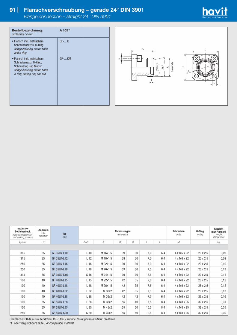
91 |
Oberfläche: CR-6: auslaufend/Neu: CR-6 frei / surface: CR-6: phase-out/New: CR-6 free*1 oder vergleichbare Güte / or comparable material
Bestellbezeichnung:ordering code:
A 105 *1
• Flansch incl. metrischem Schraubensatz u. O-Ring flange including metric bolts and o-ring
GF-…K
• Flansch incl. metrischem Schraubensatz, O-Ring, Schneidring und Mutter flange including metric bolts, o-ring, cutting ring and nut
GF-…KM
91 | Flanschverschraubung – gerade 24° DIN 3901 Flange connection – straight 24° DIN 3901
maximaler Betriebsdruck
maximum recommen-ded working pressure
Lochkreishole-
figurationTyptype
Abmessungendimensions
Schraubenbolts
O-Ringo-ring
Gewicht (nur Flansch)
weight (flange only)
kg/cm² LK RAD A D G I L M kg
315 35 GF 35LK-L10 L 10 M 16x1,5 39 30 7,0 6,4 4 x M6 x 22 20 x 2,5 0,09
315 35 GF 35LK-L12 L 12 M 18x1,5 39 30 7,0 6,4 4 x M6 x 22 20 x 2,5 0,09
250 35 GF 35LK-L15 L 15 M 22x1,5 39 30 7,0 6,4 4 x M6 x 22 20 x 2,5 0,10
250 35 GF 35LK-L18 L 18 M 26x1,5 39 30 7,5 6,4 4 x M6 x 22 20 x 2,5 0,12
315 35 GF 35LK-S16 S 16 M 24x1,5 39 30 8,5 6,4 4 x M6 x 22 20 x 2,5 0,11
100 40 GF 40LK-L15 L 15 M 22x1,5 42 35 7,0 6,4 4 x M6 x 22 26 x 2,5 0,12
100 40 GF 40LK-L18 L 18 M 26x1,5 42 35 7,5 6,4 4 x M6 x 22 26 x 2,5 0,12
100 40 GF 40LK-L22 L 22 M 30x2 42 35 7,5 6,4 4 x M6 x 22 26 x 2,5 0,13
100 40 GF 40LK-L28 L 28 M 36x2 42 42 7,5 6,4 4 x M6 x 22 26 x 2,5 0,16
100 55 GF 55LK-L28 L 28 M 36x2 55 40 7,5 8,4 4 x M8 x 25 32 x 2,5 0,31
100 55 GF 55LK-L35 L 35 M 45x2 55 50 10,5 8,4 4 x M8 x 25 32 x 2,5 0,35
250 55 GF 55LK-S20 S 20 M 30x2 55 40 10,5 8,4 4 x M8 x 25 32 x 2,5 0,30
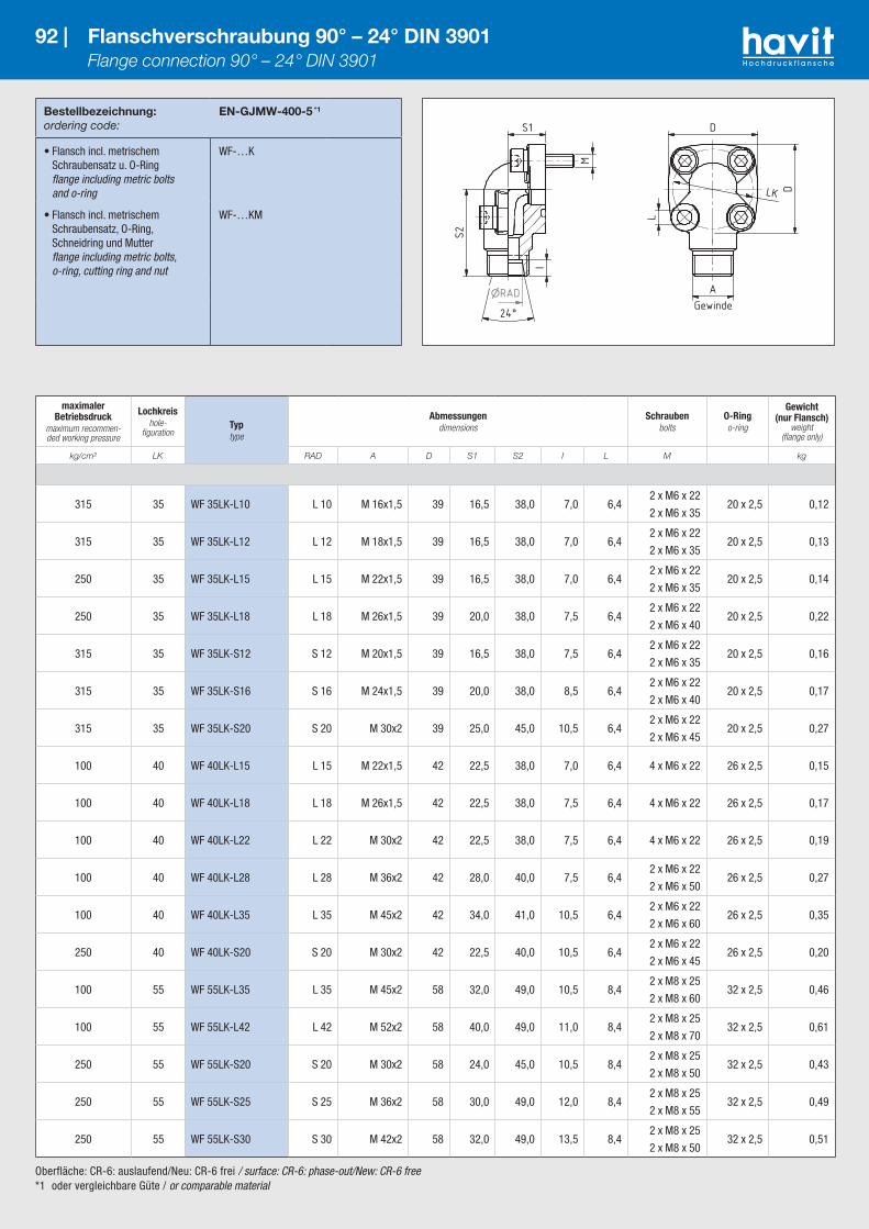
Oberfläche: CR-6: auslaufend/Neu: CR-6 frei / surface: CR-6: phase-out/New: CR-6 free*1 oder vergleichbare Güte / or comparable material
Bestellbezeichnung:ordering code:
EN-GJMW-400-5 *1
• Flansch incl. metrischem Schraubensatz u. O-Ring flange including metric bolts and o-ring
WF-…K
• Flansch incl. metrischem Schraubensatz, O-Ring, Schneidring und Mutter flange including metric bolts, o-ring, cutting ring and nut
WF-…KM
92 | Flanschverschraubung 90° – 24° DIN 3901 Flange connection 90° – 24° DIN 3901
maximaler Betriebsdruck
maximum recommen-ded working pressure
Lochkreishole-
figurationTyptype
Abmessungendimensions
Schraubenbolts
O-Ringo-ring
Gewicht (nur Flansch)
weight (flange only)
kg/cm² LK RAD A D S1 S2 I L M kg
315 35 WF 35LK-L10 L 10 M 16x1,5 39 16,5 38,0 7,0 6,42 x M6 x 22
2 x M6 x 3520 x 2,5 0,12
315 35 WF 35LK-L12 L 12 M 18x1,5 39 16,5 38,0 7,0 6,42 x M6 x 22
2 x M6 x 3520 x 2,5 0,13
250 35 WF 35LK-L15 L 15 M 22x1,5 39 16,5 38,0 7,0 6,42 x M6 x 22
2 x M6 x 3520 x 2,5 0,14
250 35 WF 35LK-L18 L 18 M 26x1,5 39 20,0 38,0 7,5 6,42 x M6 x 22
2 x M6 x 4020 x 2,5 0,22
315 35 WF 35LK-S12 S 12 M 20x1,5 39 16,5 38,0 7,5 6,42 x M6 x 22
2 x M6 x 3520 x 2,5 0,16
315 35 WF 35LK-S16 S 16 M 24x1,5 39 20,0 38,0 8,5 6,42 x M6 x 22
2 x M6 x 4020 x 2,5 0,17
315 35 WF 35LK-S20 S 20 M 30x2 39 25,0 45,0 10,5 6,42 x M6 x 22
2 x M6 x 4520 x 2,5 0,27
100 40 WF 40LK-L15 L 15 M 22x1,5 42 22,5 38,0 7,0 6,4 4 x M6 x 22 26 x 2,5 0,15
100 40 WF 40LK-L18 L 18 M 26x1,5 42 22,5 38,0 7,5 6,4 4 x M6 x 22 26 x 2,5 0,17
100 40 WF 40LK-L22 L 22 M 30x2 42 22,5 38,0 7,5 6,4 4 x M6 x 22 26 x 2,5 0,19
100 40 WF 40LK-L28 L 28 M 36x2 42 28,0 40,0 7,5 6,42 x M6 x 22
2 x M6 x 5026 x 2,5 0,27
100 40 WF 40LK-L35 L 35 M 45x2 42 34,0 41,0 10,5 6,42 x M6 x 22
2 x M6 x 6026 x 2,5 0,35
250 40 WF 40LK-S20 S 20 M 30x2 42 22,5 40,0 10,5 6,42 x M6 x 22
2 x M6 x 4526 x 2,5 0,20
100 55 WF 55LK-L35 L 35 M 45x2 58 32,0 49,0 10,5 8,42 x M8 x 25
2 x M8 x 6032 x 2,5 0,46
100 55 WF 55LK-L42 L 42 M 52x2 58 40,0 49,0 11,0 8,42 x M8 x 25
2 x M8 x 7032 x 2,5 0,61
250 55 WF 55LK-S20 S 20 M 30x2 58 24,0 45,0 10,5 8,42 x M8 x 25
2 x M8 x 5032 x 2,5 0,43
250 55 WF 55LK-S25 S 25 M 36x2 58 30,0 49,0 12,0 8,42 x M8 x 25
2 x M8 x 5532 x 2,5 0,49
250 55 WF 55LK-S30 S 30 M 42x2 58 32,0 49,0 13,5 8,42 x M8 x 25
2 x M8 x 5032 x 2,5 0,51
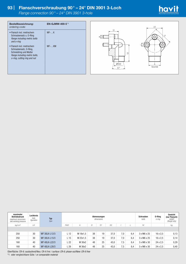
Oberfläche: CR-6: auslaufend/Neu: CR-6 frei / surface: CR-6: phase-out/New: CR-6 free*1 oder vergleichbare Güte / or comparable material
Bestellbezeichnung:ordering code:
EN-GJMW-400-5 *1
• Flansch incl. metrischem Schraubensatz u. O-Ring flange including metric bolts and o-ring
WF-…K
• Flansch incl. metrischem Schraubensatz, O-Ring, Schneidring und Mutter flange including metric bolts, o-ring, cutting ring and nut
WF-…KM
93 | Flanschverschraubung 90° – 24° DIN 3901 3-Loch Flange connection 90° – 24° DIN 3901 3-hole
maximaler Betriebsdruck
maximum recommen-ded working pressure
Lochkreishole-
figurationTyptype
Abmessungendimensions
Schraubenbolts
O-Ringo-ring
Gewicht (nur Flansch)
weight (flange only)
kg/cm² LK RAD A D S1 S2 I L M kg
250 30 WF 30LK-L12/3 L 12 M 18x1,5 38 19 37,0 7,0 6,4 3 x M6 x 25 16 x 2,5 0,13
250 30 WF 30LK-L15/3 L 15 M 22x1,5 38 19 37,0 7,0 6,4 3 x M6 x 25 16 x 2,5 0,14
160 40 WF 40LK-L22/3 L 22 M 30x2 48 25 43,0 7,5 8,4 3 x M8 x 30 24 x 2,5 0,29
160 40 WF 40LK-L28/3 L 28 M 36x2 48 25 43,0 7,5 8,4 3 x M8 x 30 24 x 2,5 0,40
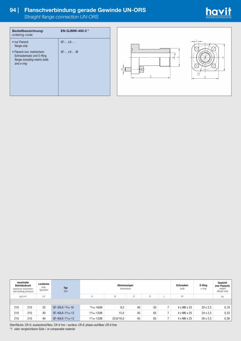
Oberfläche: CR-6: auslaufend/Neu: CR-6 frei / surface: CR-6: phase-out/New: CR-6 free*1 oder vergleichbare Güte / or comparable material
Bestellbezeichnung:ordering code:
EN-GJMW-400-5 *1
• nur Flansch flange only
GF-…LK-…
• Flansch incl. metrischem Schraubensatz und O-Ring flange including metric bolts and o-ring
GF-…LK-…M
94 | Flanschverbindung gerade Gewinde UN-ORS Straight flange connection UN-ORS
maximaler Betriebsdruck
maximum recommen-ded working pressure
Lochkreishole-
figurationTyptype
Abmessungendimensions
Schraubenbolts
O-Ringo-ring
Gewicht (nur Flansch)
weight (flange only)
kg/cm² LK A B D G L M kg
210 210 35 GF-35LK-¹³⁄₁₆-16 ¹³⁄₁₆-16UN 9,5 40 50 7 4 x M6 x 25 20 x 2,5 0,18
210 210 40 GF-40LK-1³⁄₁₆-12 1³⁄₁₆-12UN 15,0 45 65 7 4 x M6 x 25 24 x 2,5 0,33
210 210 40 GF-40LK-1⁷⁄₁₆-12 1⁷⁄₁₆-12UN 20,6/16,0 45 65 7 4 x M6 x 25 26 x 2,5 0,36

Oberfläche: CR-6: auslaufend/Neu: CR-6 frei / surface: CR-6: phase-out/New: CR-6 free*1 oder vergleichbare Güte / or comparable material
Bestellbezeichnung:ordering code:
EN-GJMW-400-5 *1
• nur Winkelflanschverschraubung flange only
WF-…LK-UN…
• Winkelflanschverschraubung incl. metrischem Schraubensatz und O-Ring flange including metric bolts and o-ring
WF-…LK-UN…M
95 | Flanschverbindung 90°-Gewinde UN-ORS Flange connection 90° UN-ORS
maximaler Betriebsdruck
maximum recommen-ded working pressure
Lochkreishole-
figurationTyptype
Abmessungendimensions
Schraubenbolts
O-Ringo-ring
Gewicht (nur Flansch)
weight (flange only)
kg/cm² LK A B D S1 S2 L M kg
210 210 30 WF-30LK-¹¹⁄₁₆ ¹¹⁄₁₆ UN 6,5 30 15 30 5,42 x M5 x 20
2 x M5 x 2515 x 2,5 0,12
210 210 30 WF 30LK-¹³⁄₁₆ ¹³⁄₁₆ UN 9,5 30 15 30 6,42 x M6 x 20
2 x M6 x 3015 x 2,5 0,11
210 210 35 WF 35LK-¹³⁄₁₆ ¹³⁄₁₆ UN 9,5 40 20 55 6,42 x M6 x 20
2 x M6 x 3018 x 2,5 0,25
210 210 40 WF 40LK-1 1UN 15,0 45 24 60 6,42 x M6 x 20
2 x M6 x 4024 x 2,5 0,59
210 210 40 WF 40LK-1⁷⁄₁₆ 1⁷⁄₁₆ UN 20,0 42 28 40 6,42 x M6 x 20
2 x M6 x 5026 x 2,5 0,26
210 210 55 WF 55LK-1¹¹⁄₁₆ 1¹¹⁄₁₆ UN 26,0 58 32 49 8,42 x M8 x 22
2 x M8 x 5032 x 2,5 0,57

Oberfläche: CR-6: auslaufend/Neu: CR-6 frei / surface: CR-6: phase-out/New: CR-6 free*1 oder vergleichbare Güte / or comparable material
Bestellbezeichnung:ordering code:
ST42.3 *1
• Flansch incl. metrischem Schraubensatz u. O-Ring flange including metric bolts and o-ring
WDS-…K
96 | 3-Loch Flansch 90° BSPP-Gewinde Stahl 3-hole flange 90° BSPP-threaded steel
maximaler Betriebsdruck
maximum recommen-ded working pressure
Lochkreishole-
figurationTyptype
Abmessungendimensions
Schraubenbolts
O-Ringo-ring
Gewicht (nur Flansch)
weight (flange only)
kg/cm² LK A B S1 S2 L M kg
315 26 WDS 05/38 G ³⁄₈" 11 17 24 5,3 3 x M5 x 20 14 x 1,78 0,16
315 26 WDS 05/12 G ¹ ⁄₂" 11 17 24 5,3 3 x M5 x 20 14 x 1,78 0,15
315 30 WDS 1/38 G ³⁄₈" 12 17 26 6,3 3 x M6 x 20 15,88 x 2,62 0,16
315 30 WDS 1/12 G ¹ ⁄₂" 12 17 26 6,3 3 x M6 x 20 15,88 x 2,62 0,15
315 40 WDS 2/12 G ¹ ⁄₂" 19 21 36 8,5 3 x M8 x 25 23,81 x 2,62 0,33
315 40 WDS 2/34 G ³⁄₄" 19 21 36 8,5 3 x M8 x 25 23,81 x 2,62 0,31
315 51 WDS 3/34 G ³⁄₄" 26 26 45 10,5 3 x M10 x 30 31,42 x 2,62 0,57
315 51 WDS 3/100 G 1" 24 26 45 10,5 3 x M10 x 30 31,42 x 2,62 0,52
315 56 WDS 3B/34 G ³⁄₄" 26 26 45 10,5 3 x M10 x 30 31,42 x 2,62 0,57
315 56 WDS 3B/100 G 1" 26 26 45 10,5 3 x M10 x 30 31,42 x 2,62 0,52

Oberfläche: CR-6: auslaufend/Neu: CR-6 frei / surface: CR-6: phase-out/New: CR-6 free*1 oder vergleichbare Güte / or comparable material
Bestellbezeichnung:ordering code:
EN-GJMW-400-5 *1
• Winkelflanschverschraubung incl. metrischem Schraubensatz und O-Ring flange including metric bolts and o-ring
WF-…LK-G…M
97 | 4-Loch Flansch 90° BSPP-Gewinde Stahl 4-hole flange 90° BSPP-threaded steel
maximaler Betriebsdruck
maximum recommen-ded working pressure
Lochkreishole-
figurationTyptype
Abmessungendimensions
Schraubenbolts
O-Ringo-ring
Gewicht (nur Flansch)
weight (flange only)
kg/cm² LK A B D S1 S2 L M kg
315 35 WF-35LK-G012 G ¹ ⁄₂" 15 39 25 45 6,42 x M6 x 22
2 x M6 x 4520 x 2,5 0,25
315 35 WF 35LK-G038 G ³⁄₈" 15 39 25 45 6,42 x M6 x 22
2 x M6 x 4520 x 2,5 0,27
250 40 WF 40LK-G012 G ¹ ⁄₂" 20 42 28 50 6,42 x M6 x 22
2 x M6 x 5026 x 2,5 0,41
160 40 WF 40LK-G034 G ³⁄₄" 20 42 28 50 6,42 x M6 x 22
2 x M6 x 5026 x 2,5 0,38
160 40 WF 40LK-G100 G 1" 20 42 34 51 6,42 x M6 x 22
2 x M6 x 6026 x 2,5 0,47
160 55 WF 55LK-G100 G 1" 26 58 40 59 8,42 x M8 x 25
2 x M8 x 7032 x 2,5 0,87
160 55 WF 55LK-G114 G 1¹ ⁄₄” 26 58 40 59 8,42 x M8 x 25
2 x M8 x 7032 x 2,5 0,73
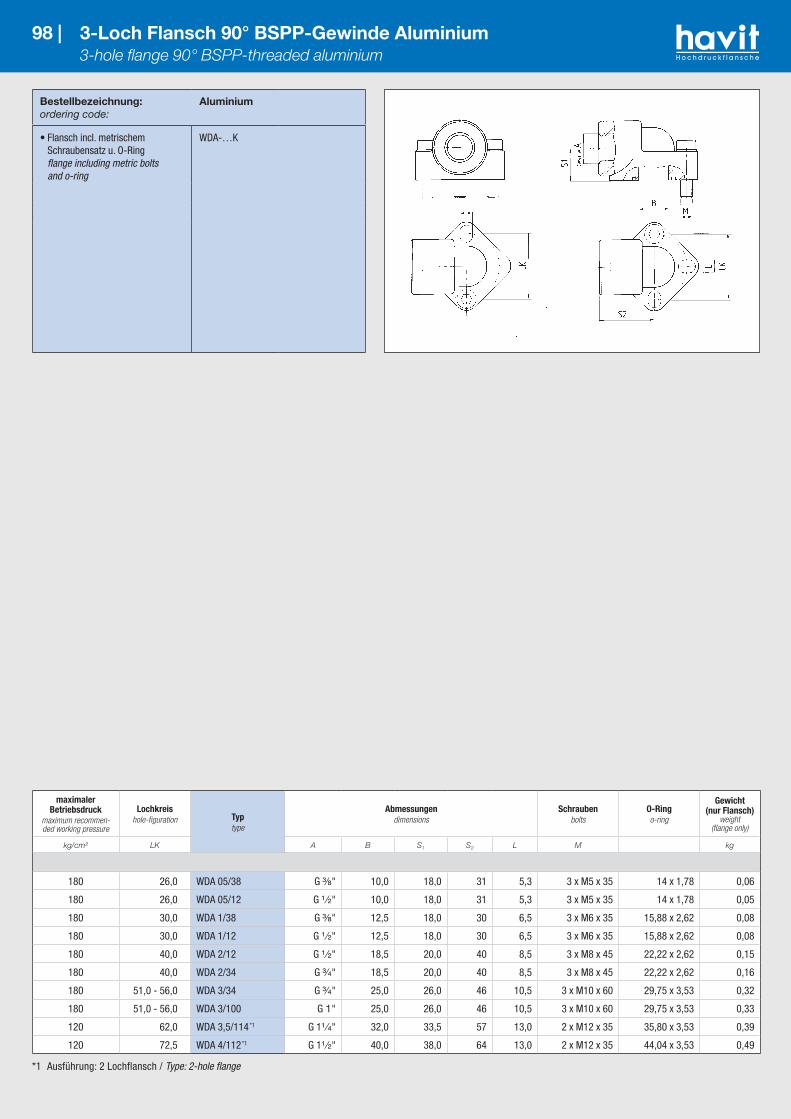
Bestellbezeichnung:ordering code:
Aluminium
• Flansch incl. metrischem Schraubensatz u. O-Ring flange including metric bolts and o-ring
WDA-…K
98 | 3-Loch Flansch 90° BSPP-Gewinde Aluminium 3-hole flange 90° BSPP-threaded aluminium
*1 Ausführung: 2 Lochflansch / Type: 2-hole flange
maximaler Betriebsdruck
maximum recommen-ded working pressure
Lochkreishole-figuration Typ
type
Abmessungendimensions
Schraubenbolts
O-Ringo-ring
Gewicht (nur Flansch)
weight (flange only)
kg/cm² LK A B S1 S2 L M kg
180 26,0 WDA 05/38 G ³⁄₈" 10,0 18,0 31 5,3 3 x M5 x 35 14 x 1,78 0,06
180 26,0 WDA 05/12 G ¹ ⁄₂" 10,0 18,0 31 5,3 3 x M5 x 35 14 x 1,78 0,05
180 30,0 WDA 1/38 G ³⁄₈" 12,5 18,0 30 6,5 3 x M6 x 35 15,88 x 2,62 0,08
180 30,0 WDA 1/12 G ¹ ⁄₂" 12,5 18,0 30 6,5 3 x M6 x 35 15,88 x 2,62 0,08
180 40,0 WDA 2/12 G ¹ ⁄₂" 18,5 20,0 40 8,5 3 x M8 x 45 22,22 x 2,62 0,15
180 40,0 WDA 2/34 G ³⁄₄" 18,5 20,0 40 8,5 3 x M8 x 45 22,22 x 2,62 0,16
180 51,0 - 56,0 WDA 3/34 G ³⁄₄" 25,0 26,0 46 10,5 3 x M10 x 60 29,75 x 3,53 0,32
180 51,0 - 56,0 WDA 3/100 G 1" 25,0 26,0 46 10,5 3 x M10 x 60 29,75 x 3,53 0,33
120 62,0 WDA 3,5/114 *1 G 1¹ ⁄₄" 32,0 33,5 57 13,0 2 x M12 x 35 35,80 x 3,53 0,39
120 72,5 WDA 4/112 *1 G 1¹ ⁄₂" 40,0 38,0 64 13,0 2 x M12 x 35 44,04 x 3,53 0,49

Bestellbezeichnung:ordering code:
Aluminium
• Flansch incl. metrischem Schraubensatz u. O-Ring flange including metric bolts and o-ring
WVA-…K
99 | 4-Loch Flansch 90° BSPP-Gewinde Aluminium 4-hole flange 90° BSPP-threaded aluminium
maximaler Betriebsdruck
maximum recommen-ded working pressure
Lochkreishole-
figurationTyptype
Abmessungendimensions
Schraubenbolts
O-Ringo-ring
Gewicht (nur Flansch)
weight (flange only)
kg/cm² LK A B D S1 S2 L M kg
180 30 WVA 38/30 G ³⁄₈" 11,5 35,0 18 40,0 6,52 x M6 x 30
2 x M6 x 4515,88 x 2,62 0,09
180 30 WVA 12/30 G ¹ ⁄₂" 11,5 35,0 18 40,0 6,52 x M6 x 30
2 x M6 x 4515,88 x 2,62 0,09
180 35 WVA 38/35 G ³⁄₈" 14,0 38,5 18 42,5 6,52 x M6 x 30
2 x M6 x 4518,72 x 2,62 0,11
180 35 WVA 12/35 G ¹ ⁄₂" 14,0 38,5 18 42,5 6,52 x M6 x 30
2 x M6 x 4518,72 x 2,62 0,10
180 40 WVA 12/40 G ¹ ⁄₂" 17,0 42,0 24 47,5 6,52 x M6 x 35
2 x M6 x 5522,22 x 2,62 0,18
180 40 WVA 34/40 G ³⁄₄" 17,0 42,0 24 47,5 6,52 x M6 x 35
2 x M6 x 5522,22 x 2,62 0,17
180 55 WVA 34/55 G ³⁄₄" 25,0 58,0 29 54,0 8,52 x M8 x 45
2 x M8 x 6029,75 x 3,53 0,31
120 55 WVA 100/55 G 1 " 25,0 58,0 29 54,0 8,52 x M8 x 45
2 x M8 x 6029,75 x 3,53 0,30

*1 oder vergleichbare Güte / or comparable material
Bestellbezeichnung:ordering code:
EN-GJMW-400-5 *1
• nur Winkelflansch verschraubung flange only
WF-…LK-E…
• Winkelflanschverschraubung incl. metrischem Schraubensatz und O-Ring flange including metric bolts and o-ring
WF-…LK-E…M
100 | 4-Loch Einschweißflansch 90° 4-hole socket weld flange 90°
maximaler Betriebsdruck
maximum recommen-ded working pressure
Lochkreishole-
figurationTyptype
Abmessungendimensions
Schraubenbolts
O-Ringo-ring
Gewicht (nur Flansch)
weight (flange only)
kg/cm² LK A B D I S1 S2 L M kg
315 35 WF-35LK-L10E 10,1 14 39 10,0 16,5 38 6,42 x M6 x 22
2 x M6 x 35 20 x 2,5 0,15
315 35 WF 35LK-L12E 12,1 14 39 10,0 16,5 38 6,42 x M6 x 22
2 x M6 x 3520 x 2,5 0,15
250 35 WF 35LK-L15E 15,1 14 39 10,0 16,5 38 6,42 x M6 x 22
2 x M6 x 3520 x 2,5 0,16
250 35 WF 35LK-L18E 18,1 15 39 10,0 20,5 38 6,42 x M6 x 22
2 x M6 x 4020 x 2,5 0,20
315 35 WF 35LK-S16E 16,1 15 39 10,0 20,5 38 6,42 x M6 x 22
2 x M6 x 4020 x 2,5 0,18
315 35 WF 35LK-S20E 20,1 15 39 10,0 25,5 45 6,42 x M6 x 25
2 x M6 x 4520 x 2,5 0,25
100 40 WF 40LK-L15E 15,1 20 42 10,0 23,0 38 6,4 4 x M6 x 22 26 x 2,5 0,24
100 40 WF 40LK-L18E 18,1 20 42 10,0 23,0 38 6,4 4 x M6 x 22 26 x 2,5 0,23
100 40 WF 40LK-L22E 22,1 20 42 10,0 23,0 38 6,4 4 x M6 x 22 26 x 2,5 0,21
100 40 WF 40LK-L28E 28,1 20 42 14,4 28,0 40 6,42 x M6 x 22
2 x M6 x 5026 x 2,5 0,27
100 40 WF 40LK-L35E 35,1 20 42 10,0 34,0 41 6,42 x M6 x 22
2 x M6 x 6026 x 2,5 0,29
100 55 WF 55LK-L35E 35,1 26 58 10,0 31,0 49 8,42 x M8 x 25
2 x M8 x 6032 x 2,5 0,51
100 55 WF 55LK-L42E 42,1 26 58 10,0 40,0 49 8,42 x M8 x 25
2 x M8 x 7032 x 2,5 0,64
250 55 WF 55LK-S20E 20,1 18 58 10,0 24,0 45 8,42 x M8 x 25
2 x M8 x 5032 x 2,5 0,46
250 55 WF 55LK-S25E 25,1 20 58 10,0 30,0 49 8,42 x M8 x 25
2 x M8 x 5532 x 2,5 0,52
250 55 WF 55LK-S30E 30,1 26 58 10,0 32,0 49 8,42 x M8 x 25
2 x M8 x 5032 x 2,5 0,53
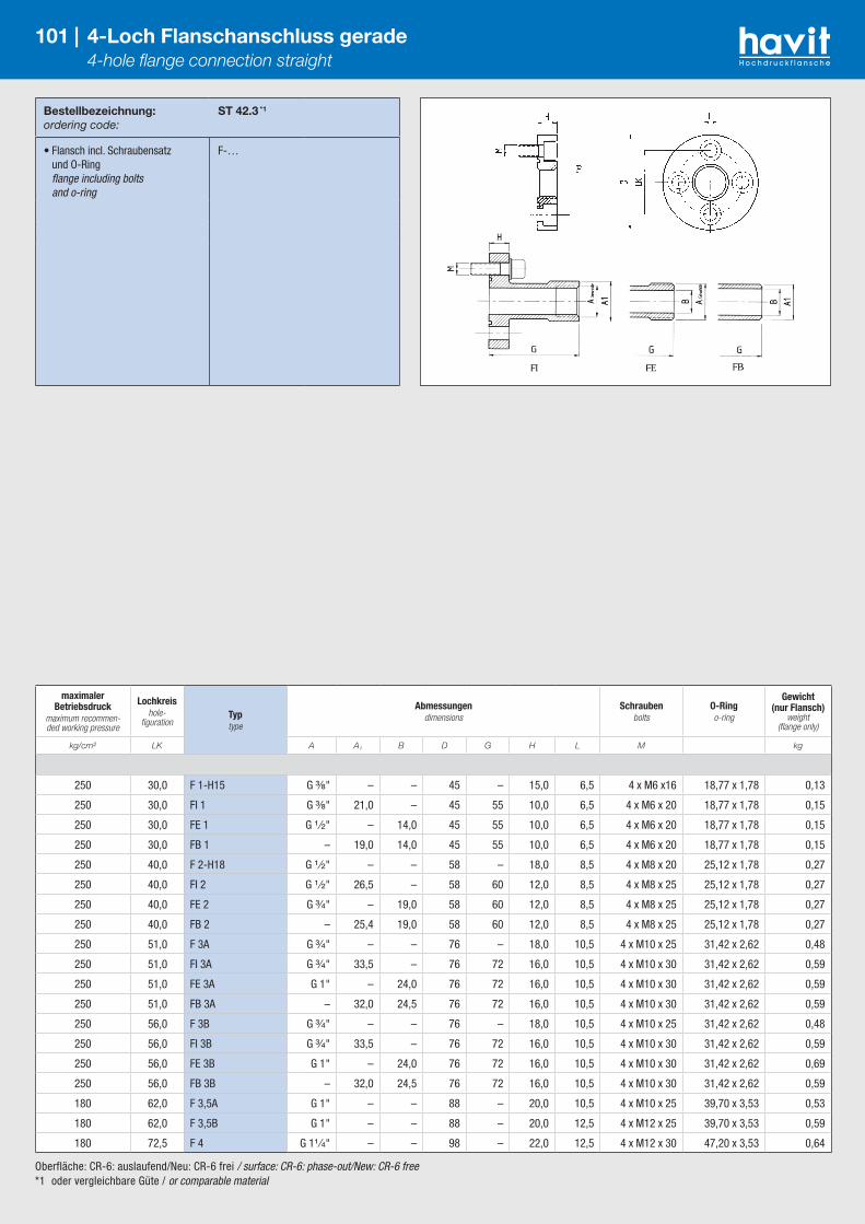
Oberfläche: CR-6: auslaufend/Neu: CR-6 frei / surface: CR-6: phase-out/New: CR-6 free*1 oder vergleichbare Güte / or comparable material
Bestellbezeichnung:ordering code:
ST 42.3 *1
• Flansch incl. Schraubensatz und O-Ring flange including bolts and o-ring
F-…
101 | 4-Loch Flanschanschluss gerade 4-hole flange connection straight
maximaler Betriebsdruck
maximum recommen-ded working pressure
Lochkreishole-
figurationTyptype
Abmessungendimensions
Schraubenbolts
O-Ringo-ring
Gewicht (nur Flansch)
weight (flange only)
kg/cm² LK A A1 B D G H L M kg
250 30,0 F 1-H15 G ³⁄₈" – – 45 – 15,0 6,5 4 x M6 x16 18,77 x 1,78 0,13
250 30,0 FI 1 G ³⁄₈" 21,0 – 45 55 10,0 6,5 4 x M6 x 20 18,77 x 1,78 0,15
250 30,0 FE 1 G ¹ ⁄₂" – 14,0 45 55 10,0 6,5 4 x M6 x 20 18,77 x 1,78 0,15
250 30,0 FB 1 – 19,0 14,0 45 55 10,0 6,5 4 x M6 x 20 18,77 x 1,78 0,15
250 40,0 F 2-H18 G ¹ ⁄₂" – – 58 – 18,0 8,5 4 x M8 x 20 25,12 x 1,78 0,27
250 40,0 FI 2 G ¹ ⁄₂" 26,5 – 58 60 12,0 8,5 4 x M8 x 25 25,12 x 1,78 0,27
250 40,0 FE 2 G ³⁄₄" – 19,0 58 60 12,0 8,5 4 x M8 x 25 25,12 x 1,78 0,27
250 40,0 FB 2 – 25,4 19,0 58 60 12,0 8,5 4 x M8 x 25 25,12 x 1,78 0,27
250 51,0 F 3A G ³⁄₄" – – 76 – 18,0 10,5 4 x M10 x 25 31,42 x 2,62 0,48
250 51,0 FI 3A G ³⁄₄" 33,5 – 76 72 16,0 10,5 4 x M10 x 30 31,42 x 2,62 0,59
250 51,0 FE 3A G 1" – 24,0 76 72 16,0 10,5 4 x M10 x 30 31,42 x 2,62 0,59
250 51,0 FB 3A – 32,0 24,5 76 72 16,0 10,5 4 x M10 x 30 31,42 x 2,62 0,59
250 56,0 F 3B G ³⁄₄" – – 76 – 18,0 10,5 4 x M10 x 25 31,42 x 2,62 0,48
250 56,0 FI 3B G ³⁄₄" 33,5 – 76 72 16,0 10,5 4 x M10 x 30 31,42 x 2,62 0,59
250 56,0 FE 3B G 1" – 24,0 76 72 16,0 10,5 4 x M10 x 30 31,42 x 2,62 0,69
250 56,0 FB 3B – 32,0 24,5 76 72 16,0 10,5 4 x M10 x 30 31,42 x 2,62 0,59
180 62,0 F 3,5A G 1" – – 88 – 20,0 10,5 4 x M10 x 25 39,70 x 3,53 0,53
180 62,0 F 3,5B G 1" – – 88 – 20,0 12,5 4 x M12 x 25 39,70 x 3,53 0,59
180 72,5 F 4 G 1¹ ⁄₄" – – 98 – 22,0 12,5 4 x M12 x 30 47,20 x 3,53 0,64

Bestellbezeichnung:ordering code:
S355J2 *1
C45
• nur Anschweißflansch weld-on flange only
VKA 32-…/AxS
• Flanschkupplung weld-on flange-coupling
VKK 28-…/AxS
• incl. Schraubensatz und O-Ring including bolts and o-ring
…/…M
102 | Anschweißflansch – zentriert – ND 160 – ISO 6164 Weld-on centering flange – ND 160 – ISO 6164
maximaler Betriebsdruck
maximum recommen-ded working pressure
DNDN Typ
type
Abmessungendimensions
Schraubenbolts
O-Ringo-ring
Gewichtweight
kg/cm² A x S LK F D H G M kg
Anschweißflansch / weld-on flange
160 12 VKA 32-12/… 16x2 44 50 – 19 43 4 x M10 x 35 16,3 x 2,4 0,40
160 16 VKA 32-16/… 20x2,5 54 60 – 19 50 4 x M10 x 35 25,3 x 2,4 0,65
160 20 VKA 32-20/… 25x3 54 60 – 19 50 4 x M10 x 35 25,3 x 2,4 0,70
160 25 VKA 32-25/… 30x4 64 70 – 19 56 4 x M12 x 35 29,8 x 2,6 0,90
160 32 VKA 32-32/… 38x5 72 80 – 24 64 4 x M12 x 40 34,5 x 2,6 1,40
160 40 VKA 32-40/… 48,3x5 80 90 – 29 68 4 x M16 x 50 46,0 x 3,0 2,00
160 50 VKA 32-50/… 60,3x6,3 98 100 – 38 80 4 x M16 x 60 53,3 x 5,33 3,00
160 65 VKA 32-65/… 76,1x7,1; 76,1x8 118 120 – 47 98 4 x M20 x 70 69,2 x 5,33 5,20
160 80 VKA 32-80/… 101,6x10 ; 101,6x8,8 175 180 – 58 135 4 x M30 x 90 100,0 x 6,0 16,50
160 100 VKA 32-100/… 114,3x11; 114,3x10 175 180 – 58 135 4 x M30 x 90 106,9 x 7,0 16,90
160 125 VKA 32-125/… 152,4x16 ; 139,7x10 200 – 245 69 150 8 x M24 x 100 132,7 x 7,0 26,95
160 150 VKA 32-150/… 177,8x17,5 ; 168,3x10 245 – 300 79 190 8 x M30 x 110 158,1 x 7,0 46,50
Flanschkupplung / weld-on flange-coupling
160 12 VKK 28-12/… 16x2 44 50 – 19 86 4 x M10 x 55 16,3 x 2,4 0,75
160 16 VKK 28-16/… 20x2,5 54 60 – 19 100 4 x M10 x 60 25,3 x 2,4 1,15
160 20 VKK 28-20/… 25x3 54 60 – 19 100 4 x M10 x 60 25,3 x 2,4 1,20
160 25 VKK 28-25/… 30x4 64 70 – 19 112 4 x M12 x 60 29,8 x 2,6 1,70
160 32 VKK 28-32/… 38x5 72 80 – 24 128 4 x M12 x 70 34,5 x 2,6 2,65
160 40 VKK 28-40/… 48,3x5 80 90 – 29 136 4 x M16 x 80 46,0 x 3,0 3,80
160 50 VKK 28-50/… 60,3x6,3 98 100 – 38 160 4 x M16 x 100 53,3 x 5,33 5,90
160 65 VKK 28-65/… 76,1x7,1; 76,1x8 118 120 – 47 196 4 x M20 x 120 69,2 x 5,33 9,90
160 80 VKK 28-80/… 101,6x10 ; 101,6x8,8 175 180 – 58 270 4 x M30 x 150 100,0 x 6,0 31,65
160 100 VKK 28-100/… 114,3x11; 114,3x10 175 180 – 58 270 4 x M30 x 150 106,9 x 7,0 32,15
160 125 VKK 28-125/… 152,4x16 ; 139,7x10 200 – 245 69 300 8 x M24 x 170 132,7 x 7,0 53,60
160 150 VKK 28-150/… 177,8x17,5 ; 168,3x10 245 – 300 79 380 8 x M30 x 200 158,1 x 7,0 92,75
Ausführung: Schweißfugenform nach DIN 2559, Material: Vierkant S355J2/C45, Stutzen S355J2, auch in 1.4404 lieferbar / Type: Welding gap form to DIN 2559, Material: Square S355J2/C45, Insert S355J2, also available in 1.4404*1 oder vergleichbare Güte / or comparable material
Bestellbezeichnung:ordering code:
S355J2 *1
C45
• nur Anschweißflansch weld-on flange only
VKA 33-…/AxS
• Flanschkupplung weld-on flange-coupling
VKK 29-…/AxS
• incl. Schraubensatz und O-Ring including bolts and o-ring
…/…M
103 | Anschweißflansch – zentriert – ND 250 – ISO 6164 Weld-on centering flange – ND 250 – ISO 6164
maximaler Betriebsdruck
maximum recommen-ded working pressure
DNDN Typ
type
Abmessungendimensions
Schraubenbolts
O-Ringo-ring
Gewichtweight
kg/cm² A x S LK F D H G M kg
Anschweißflansch / weld-on flange
250 10 VKA 33-10/… 17,2x3,6 44 50 – 20 43 4 x M10 x 35 16,3 x 2,4 0,44
250 16 VKA 33-16/… 21,3x2,6 54 60 – 20 50 4 x M10 x 35 25,3 x 2,4 0,71
250 20 VKA 33-20/… 26,9x3,6 64 70 – 20 56 4 x M12 x 35 29,8 x 2,6 0,90
250 25 VKA 33-25/… 33,7x4,5 72 80 – 25 64 4 x M12 x 40 34,5 x 2,6 1,40
250 32 VKA 33-32/… 42,4x5,6 80 90 – 30 68 4 x M16 x 50 43,0 x 3,0 2,10
250 40 VKA 33-40/… 60,3x8 98 100 – 38 80 4 x M16 x 60 53,3 x 5,33 3,10
250 50 VKA 33-50/… 76,1x10 118 120 – 47 98 4 x M20 x 70 61,0 x 5,0 5,40
250 65 VKA 33-65/…88,9x11
88,9x10 ; 88,9x12,5145 150 – 48 109 4 x M24 x 75 75,0 x 5,0 9,00
250 80 VKA 33-80/…101,6x12,5
101,6x14,2 ; 114,3x12,5175 180 – 58 135 4 x M30 x 90 88,0 x 6,0 16,90
250 100 VKA 33-100/… 139,7x17,5 200 – 245 70 150 8 x M24 x 100 115,0 x 6,0 27,85
250 125 VKA 33-125/... 168,3x20 245 – 300 80 190 8 x M30 x 110 148,0 x 7,0 47,70
250 150 VKA 33-150/... 193,7x25 290 – 355 90 190 8 x M36 x 130 183,5 x 7,0 53,20
Flanschkupplung / weld-on flange-coupling
250 10 VKK 29-10/… 17,2x3,6 44 50 – 20 86 4 x M10 x 55 16,3 x 2,4 0,80
250 16 VKK 29-16/… 21,3x2,6 54 60 – 20 100 4 x M10 x 60 25,3 x 2,4 1,22
250 20 VKK 29-20/… 26,9x3,6 64 70 – 20 112 4 x M12 x 60 29,8 x 2,6 1,70
250 25 VKK 29-25/… 33,7x4,5 72 80 – 25 128 4 x M12 x 70 34,5 x 2,6 2,70
250 32 VKK 29-32/… 42,4x5,6 80 90 – 30 136 4 x M16 x 80 43,0 x 3,0 4,00
250 40 VKK 29-40/… 60,3x8 98 100 – 38 160 4 x M16 x 100 53,3 x 5,33 6,00
250 50 VKK 29-50/… 76,1x10 118 120 – 47 196 4 x M20 x 120 61,0 x 5,0 10,30
250 65 VKK 29-65/…88,9x11
88,9x10 ; 88,9x12,5145 150 – 48 218 4 x M24 x 130 75,0 x 5,0 17,45
250 80 VKK 29-80/…101,6x12,5
101,6x14,2 ; 114,3x12,5175 180 – 58 270 4 x M30 x 150 88,0 x 6,0 32,60
250 100 VKK 29-100/… 139,7x17,5 200 – 245 70 300 8 x M24 x 170 115,0 x 6,0 54,00
250 125 VKK 29-125/... 168,3x20 245 – 300 80 380 8 x M30 x 200 148,0 x 7,0 90,00
250 150 VKK 29-150/... 193,7x25 290 – 355 90 380 8 x M36 x 220 183,5 x 7,0 105,00
Ausführung: Schweißfugenform nach DIN 2559, Material: Vierkant S355J2/C45, Stutzen S355J2, auch in 1.4404 lieferbar / Type: Welding gap form to DIN 2559, Material: Square S355J2/C45, Insert S355J2, also available in 1.4404*1 oder vergleichbare Güte / or comparable material

Ausführung: Schweißfugenform nach DIN 2559, Material: Vierkant S355J2/C45, Stutzen S355J2, auch in 1.4404 lieferbar / Type: Welding gap form to DIN 2559, Material: Square S355J2/C45, Insert S355J2, also available in 1.4404*1 oder vergleichbare Güte / or comparable material
Bestellbezeichnung:ordering code:
S355J2 *1
C45
• nur Anschweißflansch weld-on flange only
VKA 34-…/AxS
• Flanschkupplung weld-on flange-coupling
VKK 30-…/AxS
• incl. Schraubensatz und O-Ring including bolts and o-ring
…/…M
104 | Anschweißflansch – zentriert – ND 315 – ISO 6164 Weld-on centering flange – ND 315 – ISO 6164
maximaler Betriebsdruck
maximum recommen-ded working pressure
DNDN Typ
type
Abmessungendimensions
Schraubenbolts
O-Ringo-ring
Gewichtweight
kg/cm² A x S LK F D H G M kg
Anschweißflansch / weld-on flange
315 10 VKA 34-10/… 17,2x3,6 44 50 – 20 43 4 x M10 x 35 16,3 x 2,40 0,45
315 16 VKA 34-16/… 26,9x4,5 54 60 – 20 50 4 x M10 x 35 25,5 x 2,40 0,70
315 20 VKA 34-20/… 33,7x5,6 64 70 – 20 56 4 x M12 x 35 29,8 x 2,60 0,90
315 25 VKA 34-25/… 42,7x7,1 72 80 – 25 64 4 x M12 x 40 34,5 x 2,60 1,45
315 32 VKA 34-32/… 48,3x8,0; 48,3x6 80 90 – 30 68 4 x M16 x 50 43,0 x 3,00 2,20
315 40 VKA 34-40/… 60,3x10; 60,3x11 98 100 – 38 80 4 x M16 x 60 53,3 x 5,33 3,20
315 50 VKA 34-50/… 76,1x12,5 118 120 – 47 98 4 x M20 x 70 61,0 x 5,00 5,60
315 65 VKA 34-65/… 88,9x14,2 145 150 – 48 109 4 x M24 x 75 75,0 x 5,00 9,50
315 80 VKA 34-80/…
114,3x17,5; 114,3x12,5
114,3x14,2; 114,3x16;
101,6x16; 101,6x20
175 180 – 58 135 4 x M30 x 90 88,0 x 6,00 17,60
315 100 VKA 34-100/… 152,5x28; 139,7x25 200 – 245 70 150 8 x M24 x 100 115,0 x 6,00 29,30
315 125 VKA 34-125/… 177,8x30; 168,3x25 245 – 300 80 190 8 x M30 x 110 148,0 x 7,00 48,20
315 150 VKA 34-150/... 219,1x36 290 – 355 90 190 8 x M36 x 130 183,5 x 7,00 55,10
Flanschkupplung / weld-on flange-coupling
315 10 VKK 30-12/… 17,2x3,6 44 50 – 20 86 4 x M10 x 55 16,3 x 2,40 0,81
315 16 VKK 30-16/… 26,9x4,5 54 60 – 20 100 4 x M10 x 60 25,3 x 2,40 1,21
315 20 VKK 30-20/… 33,7x5,6 64 70 – 20 112 4 x M12 x 60 29,8 x 2,60 1,70
315 25 VKK 30-25/… 42,7x7,1 72 80 – 25 128 4 x M12 x 70 34,5 x 2,60 2,70
315 32 VKK 30-32/… 48,3x8,0; 48,3x6 80 90 – 30 136 4 x M16 x 80 43,0 x 3,00 4,15
315 40 VKK 30-40/… 60,3x10; 60,3x11 98 100 – 38 160 4 x M16 x 100 53,3 x 5,33 6,25
315 50 VKK 30-50/… 76,1x12,5 118 120 – 47 196 4 x M20 x 120 61,0 x 5,00 10,80
315 65 VKK 30-65/… 88,9x14,2 145 150 – 48 218 4 x M24 x 130 75,0 x 5,00 18,35
315 80 VKK 30-80/…
114,3x17,5; 114,3x12,5
114,3x14,2; 114,3x16;
101,6x16; 101,6x20
175 180 – 58 270 4 x M30 x 150 88,0 x 6,00 33,80
315 100 VKK 30-100/… 152,5x28; 139,7x25 200 – 245 70 300 8 x M24 x 170 115,0 x 6,00 57,20
315 125 VKK 30-125/… 177,8x30; 168,3x25 245 – 300 80 380 8 x M30 x 200 148,0 x 7,00 95,00
315 150 VKK 30-150/... 219,1x36 290 – 355 90 380 8 x M36 x 220 183,5 x 7,00 109,20

Bestellbezeichnung:ordering code:
S355J2 *1
C45
• nur Anschweißflansch weld-on flange only
VKA 43-…/AxS
• Flanschkupplung weld-on flange-coupling
VKK 41-…/AxS
• incl. Schraubensatz und O-Ring including bolts and o-ring
…/…M
105 | Anschweißflansch – zentriert – ND 400 – ISO 6164 Weld-on centering flange – ND 400 – ISO 6164
maximaler Betriebsdruck
maximum recommen-ded working pressure
DNDN Typ
type
Abmessungendimensions
Schraubenbolts
O-Ringo-ring
Gewichtweight
kg/cm² A x S LK F D H G M kg
Anschweißflansch / weld-on flange
400 10 VKA 43-10/… 17,2x3,6 44 50 – 20 43 4 x M10 x 35 16,3 x 2,40 0,45
400 16 VKA 43-16/… 26,9x5,6 54 60 – 20 50 4 x M10 x 35 25,3 x 2,40 0,70
400 20 VKA 43-20/… 33,7x6,3 64 70 – 20 56 4 x M12 x 35 29,8 x 2,60 0,90
400 25 VKA 43-25/… 42,7x8,0 72 80 – 25 64 4 x M12 x 40 34,5 x 2,60 1,45
400 32 VKA 43-32/… 60,3x12,5 98 100 – 38 80 4 x M16 x 60 53,3 x 5,33 2,20
400 40 VKA 43-40/… 70,0x14,2 118 120 – 47 98 4 x M20 x 70 61,0 x 5,00 3,20
400 50 VKA 43-50/… 88,9x17,5 145 150 – 48 109 4 x M24 x 75 75,0 x 5,00 5,60
400 65 VKA 43-65/… 101,6x20,0 175 180 – 58 135 4 x M30 x 90 88,0 x 6,00 9,50
400 80 VKA 43-80/… 139,7x28,0 200 – 245 70 150 8 x M24 x 100 115,0 x 6,00 17,60
400 100 VKA 43-100/… 168,3x32,0 245 – 300 80 190 8 x M30 x 110 148,0 x 7,00 29,30
400 125 VKA 43-125/… 219,1x45,0 290 – 355 90 190 8 x M36 x 130 183,5 x 7,00 48,20
Flanschkupplung / weld-on flange-coupling
400 10 VKK 41-10/… 17,2x3,6 44 50 – 20 86 4 x M10 x 55 16,3 x 2,40 0,81
400 16 VKK 41-16/… 26,9x5,6 54 60 – 20 100 4 x M10 x 60 25,3 x 2,40 1,21
400 20 VKK 41-20/… 33,7x6,3 64 70 – 20 112 4 x M12 x 60 29,8 x 2,60 1,70
400 25 VKK 41-25/… 42,7x8,0 72 80 – 25 128 4 x M12 x 70 34,5 x 2,60 2,70
400 32 VKK 41-32/… 60,3x12,5 98 100 – 38 160 4 x M16 x 100 53,3 x 5,33 4,15
400 40 VKK 41-40/… 70,0x14,2 118 120 – 45 196 4 x M20 x 120 61,0 x 5,00 6,25
400 50 VKK 41-50/… 88,9x17,5 145 150 – 48 218 4 x M24 x 130 75,0 x 5,00 10,80
400 65 VKK 41-65/… 101,6x20,0 175 180 – 58 270 4 x M30 x 150 88,0 x 6,00 18,35
400 80 VKK 41-80/… 139,7x28,0 200 – 245 70 300 8 x M24 x 170 115,0 x 6,00 33,80
400 100 VKK 41-100/… 168,3x32,0 245 – 300 80 380 8 x M30 x 200 148,0 x 7,00 57,20
400 125 VKK 41-125/… 219,1x45,0 290 – 355 90 380 8 x M36 x 220 183,5 x 7,00 95,00
Ausführung: Schweißfugenform nach DIN 2559, Material: Vierkant S355J2/C45, Stutzen S355J2, auch in 1.4404 lieferbar / Type: Welding gap form to DIN 2559, Material: Square S355J2/C45, Insert S355J2, also available in 1.4404*1 oder vergleichbare Güte / or comparable material

106 |
*1 oder vergleichbare Güte (auch in 1.4404 lieferbar) / or comparable material (also available in 1.4404)
106 | Blindstopfen – zentriert – ND 160 – ISO 6164 Centering flange plug – ND 160 – ISO 6164
maximaler Betriebsdruck
maximum recommen-ded working pressure
DNDN Typ
type
Abmessungendimensions
Schraubenbolts
O-Ringo-ring
Gewicht (nur Blind-
stopfen) weight (flange
plug only)
kg/cm² A1 A2 LK F D G H M kg
Blindflansch mit Nut / flange plug with o-ring groove
160 12 VKB-12-160KM 28,0 17,5 44,0 50,0 – 25,0 11,5 4 x M10x35 16,3x2,4 –
160 16 VKB-16-160KM38,0 27,0 54,0 60,0 – 25,0 11,5 4 x M10x35 25,3x2,4 –
160 20 VKB-20-160KM
160 25 VKB-25-160KM 46,0 34,0 64,0 70,0 – 25,0 12,5 4 x M12x35 29,8x2,6 –
160 32 VKB-32-160KM 54,5 43,0 72,0 80,0 – 30,0 14,5 4 x M12x40 34,5x2,6 –
160 40 VKB-40-160KM 60,0 48,3 80,0 90,0 – 35,0 16,5 4 x M16x50 43,0x3,0 –
160 50 VKB-50-160KM 76,0 60,3 98,0 100,0 – 43,0 24,0 4 x M16x60 53,3x5,33 –
160 65 VKB-65-160KM 92,0 77,0 118,0 120,0 – 52,0 25,0 4 x M20x70 61,0x5,0 –
160 80 VKB-80-160KM135,0 114,5 175,0 180,0 – 63,0 33,0 4 x M30x90 88,0x6,0 –
160 100 VKB-100-160KM
160 125 VKB-125-160KM 168,0 153,0 200,0 – 245,0 75,0 39,0 8 x M24x100 115,0x6,0 –
160 150 VKB-150-160KM 210,0 178,0 245,0 – 300,0 90,0 45,0 8 x M30x110 148,0x7,0 –
Blindflansch ohne Nut / flange plug without o-ring groove
160 12 G-VKB-12-160K 28,0 17,5 44,0 50,0 – 20,0 8,0 – – –
160 16 G-VKB-16-160K38,0 27,0 54,0 60,0 – 20,0 8,0 – – –
160 20 G-VKB-20-160K
160 25 G-VKB-25-160K 46,0 34,0 64,0 70,0 – 20,0 9,0 – – –
160 32 G-VKB-32-160K 54,5 43,0 72,0 80,0 – 25,0 11,0 – – –
160 40 G-VKB-40-160K 60,0 48,3 80,0 90,0 – 30,0 12,5 – – –
160 50 G-VKB-50-160K 76,0 60,3 98,0 100,0 – 38,0 18,0 – – –
160 65 G-VKB-65-160K 92,0 77,0 118,0 120,0 – 47,0 18,0 – – –
160 80 G-VKB-80-160K135,0 114,5 175,0 180,0 – 58,0 24,0 – – –
160 100 G-VKB-100-160K
160 125 G-VKB-125-160K 168,0 153,0 200,0 – 245,0 70,0 33,0 – – –
160 150 G-VKB-150-160K 210,0 178,0 245,0 – 300,0 82,0 37,0 – – –
Bestellbezeichnung:ordering code:
S355J2 *1
• Blindflansch mit Nut (Blindstopfen mit Nut inkl. Vierkant- bzw. Rund-flansch, O-Ring und Schrauben) flange plug with o-ring groove (flange plug including square or round flange respectively, o-ring and bolts)
VKB-... -160KM
• Blindflansch ohne Nut (Blind-stopfen ohne Nut inkl. Vierkant- bzw. Rundflansch) flange plug without o-ring groove (flange plug including square or round flange respectively)
G-VKB-... -160K

107 |
*1 oder vergleichbare Güte (auch in 1.4404 lieferbar) / or comparable material (also available in 1.4404)
107 | Blindstopfen – zentriert – ND 250 ND 315 – ISO 6164 Centering flange plug – ND 250 ND 315 – ISO 6164
maximaler Betriebsdruck
maximum recommen-ded working pressure
DNDN Typ
type
Abmessungendimensions
Schraubenbolts
O-Ringo-ring
Gewicht (nur Blind-
stopfen) weight (flange
plug only)
kg/cm² A1 A2 LK F D G H M kg
Blindflansch mit Nut / flange plug with o-ring groove
250/315 10 VKB 10 28,0 17,5 44,0 50,0 – 25,0 11,5 4 x M10x35 16,3 x 2,40 0,08
250/315 16 VKB 16 38,0 27,0 54,0 60,0 – 25,0 11,5 4 x M10x35 25,3 x 2,40 0,16
250/315 20 VKB 20 46,0 34,0 64,0 70,0 – 25,0 12,5 4 x M12x35 29,8 x 2,60 0,25
250/315 25 VKB 25 54,5 43,0 72,0 80,0 – 30,0 14,5 4 x M12x40 34,5 x 2,60 0,44
250/315 32 VKB 32 60,0 48,3 80,0 90,0 – 35,0 16,5 4 x M16x50 43,0 x 3,00 0,62
250/315 40 VKB 40 76,0 60,3 98,0 100,0 – 43,0 24,0 4 x M16x60 53,3 x 5,33 1,24
250/315 50 VKB 50 92,0 77,0 118,0 120,0 – 52,0 25,0 4 x M20x70 61,0 x 5,00 2,25
250/315 65 VKB 65 116,0 89,0 145,0 150,0 – 53,0 29,0 4 x M24x75 75,0 x 5,00 3,52
250/315 80 VKB 80 135,0 114,5 175,0 180,0 – 63,0 33,0 4 x M30x90 88,0 x 6,00 6,04
250/315 100 VKB 100 168,0 153,0 200,0 – 245,0 75,0 39,0 8 x M24x100 115,0 x 6,00 11,86
250/315 125 VKB 125 210,0 178,0 245,0 – 300,0 90,0 45,0 8 x M30x110 148,0 x 7,00 20,82
250/315 150 VKB 150 245,0 219,1 290,0 – 355,0 90,0 50,0 8 x M36x130 183,5 x 7,00 30,01
Blindflansch ohne Nut / flange plug without o-ring groove
250/315 10 G-VKB 10 28,0 17,5 44,0 50,0 – 20,0 8,0 – – 0,06
250/315 16 G-VKB 16 38,0 27,0 54,0 60,0 – 20,0 8,0 – – 0,13
250/315 20 G-VKB 20 46,0 34,0 64,0 70,0 – 20,0 9,0 – – 0,20
250/315 25 G-VKB 25 54,5 43,0 72,0 80,0 – 25,0 11,0 – – 0,36
250/315 32 G-VKB 32 60,0 48,3 80,0 90,0 – 30,0 12,5 – – 0,53
250/315 40 G-VKB 40 76,0 60,3 98,0 100,0 – 38,0 18,0 – – 1,08
250/315 50 G-VKB 50 92,0 77,0 118,0 120,0 – 47,0 18,0 – – 2,00
250/315 65 G-VKB 65 116,0 89,0 145,0 150,0 – 48,0 21,0 – – 3,06
250/315 80 G-VKB 80 135,0 114,5 175,0 180,0 – 58,0 24,0 – – 5,45
250/315 100 G-VKB 100 168,0 153,0 200,0 – 245,0 70,0 33,0 – – 11,09
250/315 125 G-VKB 125 210,0 178,0 245,0 – 300,0 82,0 37,0 – – 18,85
250/315 150 G-VKB 150 245,0 219,1 290,0 – 355,0 85,0 42,0 – – 28,25
Bestellbezeichnung:ordering code:
S355J2 *1
• nur Blindstopfen mit Nut flange plug with o-ring groove only
VKB-…
• nur Blindstopfen ohne Nut flange plug without o-ring groove only
G-VKB-…
• Blindflansch mit Nut (Blindstopfen mit Nut inkl. Vierkant- bzw. Rundflansch, O-Ring und Schrauben) flange plug with o-ring groove (flange plug including square or round flange respectively, o-ring and bolts)
VKB-... KM
• Blindflansch ohne Nut (Blindstopfen ohne Nut inkl. Vier-kant- bzw. Rundflansch) flange plug without o-ring groove (flange plug including square or round flange respectively)
G-VKB-... K

*1 oder vergleichbare Güte (auch in 1.4404 lieferbar) / or comparable material (also available in 1.4404)
108 | Blindstopfen – zentriert – ND 400 – ISO 6164 Centering flange plug – ND 400 – ISO 6164
Bestellbezeichnung:ordering code:
S355J2 *1
• Blindflansch mit Nut (Blindstopfen mit Nut inkl. Vierkant- bzw. Rund-flansch, O-Ring und Schrauben) flange plug with o-ring groove (flange plug including square or round flange respectively, o-ring and bolts)
VKB-... -400KM
• Blindflansch ohne Nut (Blind-stopfen ohne Nut inkl. Vierkant- bzw. Rundflansch) flange plug without o-ring groove (flange plug including square or round flange respectively)
G-VKB-... -400K
maximaler Betriebsdruck
maximum recommen-ded working pressure
DNDN Typ
type
Abmessungendimensions
Schraubenbolts
O-Ringo-ring
Gewicht (nur Blind-
stopfen) weight (flange
plug only)
kg/cm² A1 A2 LK F D G H M kg
Blindflansch mit Nut / flange plug with o-ring groove
400 10 VKB-10-400KM 28,0 17,5 44,0 50,0 – 25,0 11,5 4 x M10x35 16,3x2,4 –
400 16 VKB-16-400KM 38,0 27,0 54,0 60,0 – 25,0 11,5 4 x M10x35 25,3x2,4 –
400 20 VKB-20-400KM 46,0 34,0 64,0 70,0 – 25,0 12,5 4 x M12x35 29,8x2,6 –
400 25 VKB-25-400KM 54,5 43,0 72,0 80,0 – 30,0 14,5 4 x M12x40 34,5x2,6 –
400 32 VKB-32-400KM 76,0 60,3 98,0 100,0 – 43,0 24,0 4 x M16x60 53,3x5,33 –
400 40 VKB-40-400KM 92,0 77,0 118,0 120,0 – 52,0 25,0 4 x M20x70 61,0x5,0 –
400 50 VKB-50-400KM 116,0 89,0 145,0 150,0 – 53,0 29,0 4 x M24x75 75,0x5,0 –
400 65 VKB-65-400KM 135,0 114,5 175,0 180,0 – 63,0 33,0 4 x M30x90 88,0x6,0 –
400 80 VKB-80-400KM 168,0 153,0 200,0 – 245,0 75,0 39,0 8 x M24x100 115,0x6,0 –
400 100 VKB-100-400KM 210,0 178,0 245,0 – 300,0 90,0 45,0 8 x M30x110 148,0x7,0 –
400 125 VKB-125-400KM 245,0 219,1 290,0 – 355,0 90,0 50,0 8 x M36x130 183,5x7,0 –
Blindflansch ohne Nut / flange plug without o-ring groove
400 10 G-VKB-10-400K 28,0 17,5 44,0 50,0 – 20,0 8,0 – – –
400 16 G-VKB-16-400K 38,0 27,0 54,0 60,0 – 20,0 8,0 – – –
400 20 G-VKB-20-400K 46,0 34,0 64,0 70,0 – 20,0 9,0 – – –
400 25 G-VKB-25-400K 54,5 43,0 72,0 80,0 – 25,0 11,0 – – –
400 32 G-VKB-32-400K 76,0 60,3 98,0 100,0 – 38,0 18,0 – – –
400 40 G-VKB-40-400K 92,0 77,0 118,0 120,0 – 47,0 18,0 – – –
400 50 G-VKB-50-400K 116,0 89,0 145,0 150,0 – 48,0 21,0 – – –
400 65 G-VKB-65-400K 135,0 114,5 175,0 180,0 – 58,0 24,0 – – –
400 80 G-VKB-80-400K 168,0 153,0 200,0 – 245,0 70,0 33,0 – – –
400 100 G-VKB-100-400K 210,0 178,0 245,0 – 300,0 82,0 37,0 – – –
400 125 G-VKB-125-400K 245,0 219,1 290,0 – 355,0 85,0 42,0 – – –

*1 oder vergleichbare Güte (auch in 1.4404 lieferbar) / or comparable material (also available in 1.4404)
Bestellbezeichnung:ordering code:
S355J2 *1
C15
• nur Winkelflansch elbow only
VKW-…
• incl. Schraubensatz und O-Ring including bolts and o-ring
VKW-…M
109 | 90° Anschweißflansch – zentriert – ISO 6164 90° weld-on centering flange – ISO 6164
maximaler Betriebsdruck
maximum recommen-ded working pressure
DNDN Typ
type
Abmessungendimensions
Schraubenbolts
O-Ringo-ring
Gewichtweight
kg/cm² A x S LK F S1 S2 H G L M kg
90° Winkelflansch / 90° elbow
250 10 VKW 10 17,2x3,6 44 50 17 55 29 80 11 4/M10x40 16,3 x 2,40 –
250 16 VKW 16 21,3x2,6 54 60 23 65 41 95 11 4/M10x45 25,3 x 2,40 –
250 20 VKW 20 26,9x3,6 64 70 26 75 47 110 13 4/M12x60 29,8 x 2,60 –
250 25 VKW 25 33,7x4,5 72 80 30 90 56 130 13 4/M12x65 34,5 x 2,60 –
250 32 VKW 32 42,4x5,6 80 90 35 95 64 140 17 4/M16x80 43,0 x 3,00 3,2
250 40 VKW 40 60,3x8 ; 60,3x10 98 100 40 105 76 155 17 4/M16x100 53,3 x 5,33 4,9/5,1
250 50 VKW 50 76,1x10 ; 76,1x12,5 118 120 53 115 100 175 22 4/M20x125 61,0 x 5,00 8,2/9,1
250 65 VKW 65 88,9x11 ; 88,9x14,2 145 150 64 125 120 200 25 4/M24x150 75,0 x 5,00 16,1/16,8
250 80 VKW 80114,3x12,5
101,6x14,2 ; 114,3x17,5175 180 73 130 140 220 32 4/M30x180 88,0 x 6,00
24,9
26,3/26,8

T-Flanschverbinder ist auch mit unterschiedlichen Abgängen bzw. Rohrabmessungen lieferbar. Beispiel: I = DN 25/33,7x4,5, II = DN 16/21,3x2,6, III = DN 20/29,9x3,6, Bestell-Nr. VKV-25/33,7x4,5 – 16/21,3x2,6 – 20/26,9x3,6 / T-flange connector can also be supplied with different sizes or different tube
Bestellbezeichnung:ordering code:
S355J2 *1 1.4404*1
316L
• nur T-Flanschverbinder T-flange connector only
VKV-… VKV-X-…
• incl. Flansch, Schrauben und O-Ring including flange, bolts and o-ring
VKV-…KM VKV-X-…KMX
110 | T-Flanschverbinder T-flange connector
maximaler Betriebsdruck *
maximum recommen-ded working pressure
DNDN Typ
type
Abmessungendimensions
Schraubenbolts
O-Ringo-ring
Gewichtweight
kg/cm² AxS (I, II, III) LK F G M kg
T-Flanschverbinder / T-flange connector
400 10 VKV 10
Abhängig von der Anwendung
Dependent on use
44 50 100 12/M10x35 16,3 x 2,40 1,7
400 16 VKV 16 54 60 110 12/M10x35 25,3 x 2,40 –
400 20 VKV 20 64 70 115 12/M12x35 29,8 x 2,60 3,8
400 25 VKV 25 72 80 125 12/M12x40 34,5 x 2,60 5,4
400 32 VKV 32 80 90 140 12/M16x50 43,0 x 3,00 7,4
400 40 VKV 40 98 100 160 12/M16x60 53,3 x 5,33 9,8
400 50 VKV 50 118 120 180 12/M20x70 61,0 x 5,00 15,4
400 65 VKV 65 145 150 200 12/M24x75 75,0 x 5,00 27,1
400 80 VKV 80 175 180 240 12/M30x90 88,0 x 6,00 48,2
dimensions. Example: I = DN 25/33,7x4,5, II = DN 16/21,3x2,6, III = DN 20/29,9x3,6, Order no. VKV-25/33,7x4,5 – 16/21,3x2,6 – 20/26,9x3,6.*1 oder vergleichbare Güte / or comparable material
* Der angeführte maximale Betriebsdruck ist bezogen auf den Flansch! Der tatsächliche Betriebsdruck wird bestimmt durch das Rohr (Wandstärke) sowie die Güte des Rohres! The maximum recommended working pressure is based on the flange. The working pressure of the system is determined by the tube (thickness) and by the steel quality of the tube!
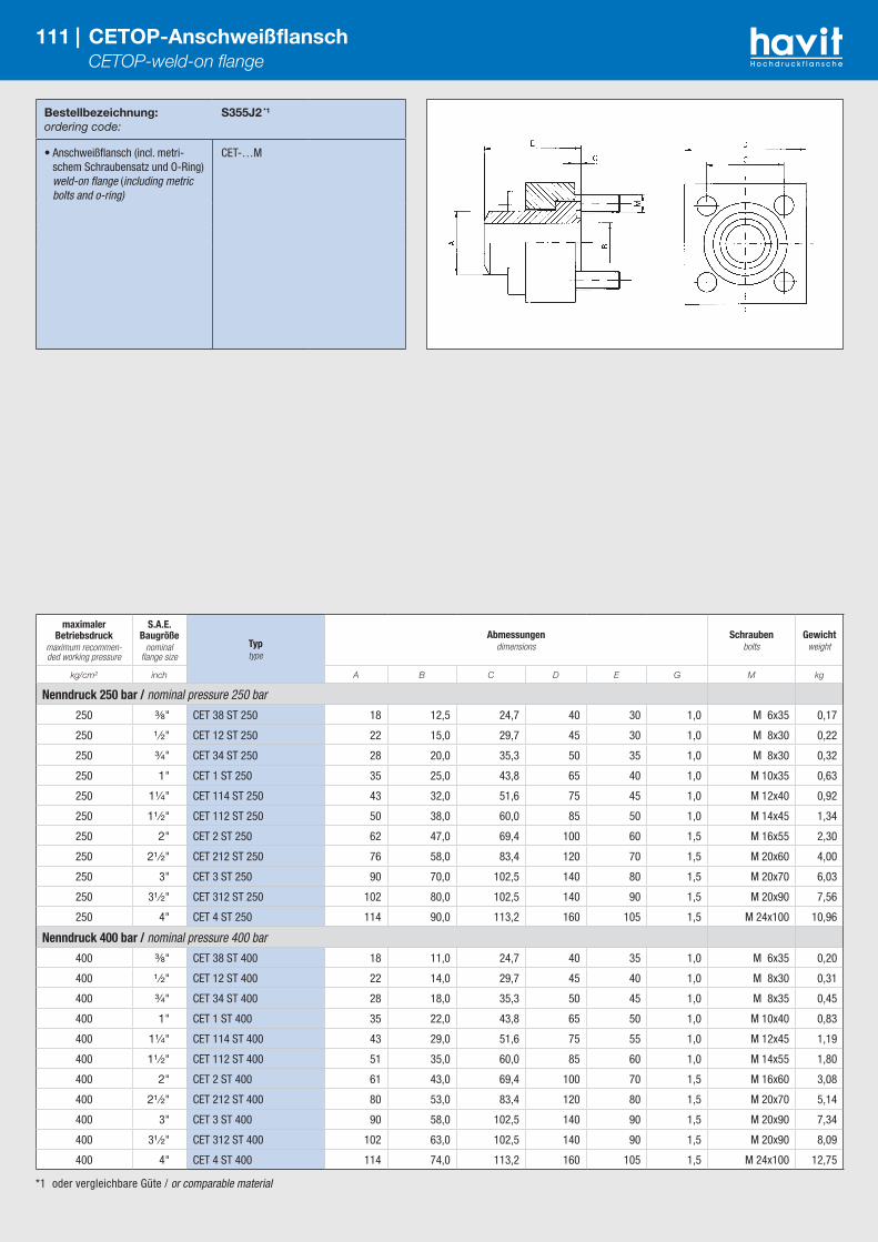
*1 oder vergleichbare Güte / or comparable material
Bestellbezeichnung:ordering code:
S355J2 *1
• Anschweißflansch (incl. metri-schem Schraubensatz und O-Ring) weld-on flange (including metric bolts and o-ring)
CET-…M
111 | CETOP-Anschweißflansch CETOP-weld-on flange
maximaler Betriebsdruck
maximum recommen-ded working pressure
S.A.E. Baugröße
nominal flange size
Typtype
Abmessungendimensions
Schraubenbolts
Gewichtweight
kg/cm² inch A B C D E G M kg
Nenndruck 250 bar / nominal pressure 250 bar
250 ³⁄₈" CET 38 ST 250 18 12,5 24,7 40 30 1,0 M 6x35 0,17
250 ¹ ⁄₂" CET 12 ST 250 22 15,0 29,7 45 30 1,0 M 8x30 0,22
250 ³⁄₄" CET 34 ST 250 28 20,0 35,3 50 35 1,0 M 8x30 0,32
250 1" CET 1 ST 250 35 25,0 43,8 65 40 1,0 M 10x35 0,63
250 1¹⁄₄" CET 114 ST 250 43 32,0 51,6 75 45 1,0 M 12x40 0,92
250 1¹ ⁄₂" CET 112 ST 250 50 38,0 60,0 85 50 1,0 M 14x45 1,34
250 2" CET 2 ST 250 62 47,0 69,4 100 60 1,5 M 16x55 2,30
250 2¹ ⁄₂" CET 212 ST 250 76 58,0 83,4 120 70 1,5 M 20x60 4,00
250 3" CET 3 ST 250 90 70,0 102,5 140 80 1,5 M 20x70 6,03
250 3¹ ⁄₂" CET 312 ST 250 102 80,0 102,5 140 90 1,5 M 20x90 7,56
250 4" CET 4 ST 250 114 90,0 113,2 160 105 1,5 M 24x100 10,96
Nenndruck 400 bar / nominal pressure 400 bar
400 ³⁄₈" CET 38 ST 400 18 11,0 24,7 40 35 1,0 M 6x35 0,20
400 ¹ ⁄₂" CET 12 ST 400 22 14,0 29,7 45 40 1,0 M 8x30 0,31
400 ³⁄₄" CET 34 ST 400 28 18,0 35,3 50 45 1,0 M 8x35 0,45
400 1" CET 1 ST 400 35 22,0 43,8 65 50 1,0 M 10x40 0,83
400 1¹⁄₄" CET 114 ST 400 43 29,0 51,6 75 55 1,0 M 12x45 1,19
400 1¹ ⁄₂" CET 112 ST 400 51 35,0 60,0 85 60 1,0 M 14x55 1,80
400 2" CET 2 ST 400 61 43,0 69,4 100 70 1,5 M 16x60 3,08
400 2¹ ⁄₂" CET 212 ST 400 80 53,0 83,4 120 80 1,5 M 20x70 5,14
400 3" CET 3 ST 400 90 58,0 102,5 140 90 1,5 M 20x90 7,34
400 3¹ ⁄₂" CET 312 ST 400 102 63,0 102,5 140 90 1,5 M 20x90 8,09
400 4" CET 4 ST 400 114 74,0 113,2 160 105 1,5 M 24x100 12,75

*1 oder vergleichbare Güte / or comparable material
Bestellbezeichnung:ordering code:
S355J2 *1
• Flanschkupplung (incl. metrischem Schraubensatz und O-Ring) flange-coupling (including metric bolts and o-ring)
D-CET-…M
112 | Cetop-Anschweißflanschkupplung Cetop-weld-on flange-coupling
maximaler Betriebsdruck
maximum recommen-ded working pressure
S.A.E. Baugröße
nominal flange size
Typtype
Abmessungendimensions
Schraubenbolts
Gewichtweight
kg/cm² inch A B C D E G M kg
Nenndruck 250 bar / nominal pressure 250 bar
250 ³⁄₈" DCET 38 ST/250 18 12,5 24,7 40 60 2 M 6x45 0,42
250 ¹ ⁄₂" DCET 12 ST/250 22 15,0 29,7 45 60 2 M 8x45 0,52
250 ³⁄₄" DCET 34 ST/250 28 20,0 35,3 50 70 2 M 8x45 0,68
250 1" DCET 1 ST/250 35 25,0 43,8 65 80 2 M 10x50 1,30
250 1¹⁄₄" DCET 114 ST/250 43 32,0 51,6 75 90 2 M 12x60 1,98
250 1¹ ⁄₂" DCET 112 ST/250 50 38,0 60,0 85 100 2 M 14x70 2,79
250 2" DCET 2 ST/250 62 47,0 69,4 100 120 3 M 16x90 4,67
250 2¹ ⁄₂" DCET 212 ST/250 76 58,0 83,4 120 140 3 M 20x100 7,96
250 3" DCET 3 ST/250 90 70,0 102,5 140 160 3 M 20x110 11,80
250 3¹ ⁄₂" DCET 312 ST/250 102 80,0 102,5 140 180 3 M 20x130 14,10
250 4" DCET 4 ST/250 114 90,0 113,2 160 210 3 M 24x150 21,60
Nenndruck 400 bar / nominal pressure 400 bar
400 ³⁄₈" DCET 38 ST/400 18 11,0 24,7 40 70 2 M 6x45 0,47
400 ¹ ⁄₂" DCET 12 ST/400 22 14,0 29,7 45 80 2 M 8x50 0,63
400 ³⁄₄" DCET 34 ST/400 28 18,0 35,2 50 90 2 M 8x60 0,90
400 1" DCET 1 ST/400 35 22,0 43,8 65 100 2 M 10x70 1,73
400 1¹⁄₄" DCET 114 ST/400 44 29,0 51,6 75 110 2 M 12x80 2,62
400 1¹ ⁄₂" DCET 112 ST/400 51 35,0 60,0 85 120 2 M 14x90 3,76
400 2" DCET 2 ST/400 61 43,0 69,4 100 140 3 M 16x100 6,40
400 2¹ ⁄₂" DCET 212 ST/400 80 53,0 83,4 120 160 3 M 20x110 10,50
400 3" DCET 3 ST/400 90 58,0 102,5 140 180 3 M 20x130 16,40
400 3¹ ⁄₂" DCET 312 ST/400 102 63,0 102,5 140 180 3 M 20x130 16,70
400 4" DCET 4 ST/400 114 74,0 113,2 160 210 3 M 24x160 25,00
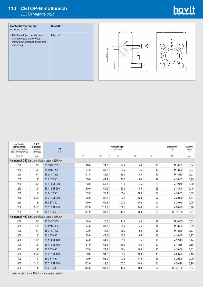
*1 oder vergleichbare Güte / or comparable material
Bestellbezeichnung:ordering code:
S355J2 *1
• Blindflansch (incl. metrischem Schraubensatz und O-Ring) flange plug (including metric bolts and o-ring)
BS-…M
113 | CETOP-Blindflansch CETOP-flange plug
maximaler Betriebsdruck
maximum recommen-ded working pressure
S.A.E. Baugröße
nominal flange size
Typtype
Abmessungendimensions
Schraubenbolts
Gewichtweight
kg/cm² inch A B C D E M kg
Nenndruck 250 bar / nominal pressure 250 bar
250 ³⁄₈" BS 38 ST 250 18,0 24,5 24,7 40 15 M 6x35 0,04
250 ¹ ⁄₂" BS 12 ST 250 24,0 30,2 29,7 45 16 M 8x30 0,07
250 ³⁄₄" BS 34 ST 250 31,5 38,1 35,3 50 17 M 8x30 0,13
250 1" BS 1 ST 250 38,0 44,4 43,8 65 19 M 10x35 0,19
250 1¹⁄₄" BS 114 ST 250 43,0 50,8 51,6 75 23 M 12x40 0,30
250 1¹ ⁄₂" BS 112 ST 250 50,0 60,3 60,0 85 26 M 14x45 0,46
250 2" BS 2 ST 250 62,0 71,4 69,4 100 31 M 16x55 0,82
250 2¹ ⁄₂" BS 212 ST 250 76,0 87,2 83,4 120 37 M 20x60 1,44
250 3" BS 3 ST 250 90,0 101,6 102,5 140 42 M 20x70 2,25
250 3¹ ⁄₂" BS 312 ST 250 102,0 119,0 102,5 140 54 M 20x90 3,90
250 4" BS 4 ST 250 114,0 131,0 113,2 160 62 M 24x100 5,54
Nenndruck 400 bar / nominal pressure 400 bar
400 ³⁄₈" BS 38 ST 400 18,0 26,0 24,7 40 17 M 6x35 0,05
400 ¹ ⁄₂" BS 12 ST 400 24,0 31,8 29,7 45 14 M 8x30 0,09
400 ³⁄₄" BS 34 ST 400 32,0 41,3 35,3 50 15 M 8x35 0,17
400 1" BS 1 ST 400 38,0 47,6 43,8 65 16 M 10x40 0,27
400 1¹⁄₄" BS 114 ST 400 44,0 54,0 51,6 75 16 M 12x45 0,44
400 1¹ ⁄₂" BS 112 ST 400 51,0 63,5 60,0 85 19 M 14x55 0,65
400 2" BS 2 ST 400 67,0 79,4 69,4 100 30 M 16x60 1,32
400 2¹ ⁄₂" BS 212 ST 400 80,0 94,2 83,4 120 45 M 20x70 2,13
400 3" BS 3 ST 400 90,0 104,0 102,5 140 55 M 20x90 3,00
400 3¹ ⁄₂" BS 312 ST 400 102,0 119,0 102,5 140 54 M 20x90 3,90
400 4" BS 4 ST 400 114,0 131,0 113,2 160 62 M 24x100 5,54

*1 oder vergleichbare Güte / or comparable material
Bestellbezeichnung:ordering code:
S355J2 *1
• nur Flansch flange only
CET-…/90...
• incl. metrischem Schraubensatz und O-Ring including metric bolts and o-ring
CET-…/90…M
114 | CETOP 90° Anschweißflansch CETOP 90° weld-on flange
maximaler Betriebsdruck
maximum recommen-ded working pressure
S.A.E. Baugröße
nominal flange size
Typtype
Abmessungendimensions
Schraubenbolts
Gewichtweight
kg/cm² inch A B C D F H L S2 M kg
Nenndruck 250 bar / nominal pressure 250 bar
250 ³⁄₈" CET 38 ST90 250 18 12,5 24,7 40 12,5 12 6,8 32 M 6x30 0,24
250 ¹ ⁄₂" CET 12 ST90 250 22 15,0 29,7 45 15,0 17 9,0 40 M 8x40 0,40
250 ³⁄₄" CET 34 ST90 250 28 20,0 35,3 50 20,0 19 9,0 42 M 8x45 0,57
250 1" CET 1 ST90 250 35 25,0 43,8 65 25,0 24 11,0 50 M 10x55 1,21
250 1¹⁄₄" CET 114 ST90 250 43 32,0 51,6 75 32,0 30 13,0 56 M 12x70 1,92
250 1¹ ⁄₂" CET 112 ST90 250 50 38,0 60,0 85 38,0 34 15,0 65 M 14x80 2,84
250 2" CET 2 ST90 250 62 47,0 69,4 100 47,0 42 17,0 75 M 16x100 4,75
250 2¹ ⁄₂" CET 212 ST90 250 76 58,0 83,4 120 58,0 53 21,0 85 M 20x120 8,67
250 3" CET 3 ST90 250 90 68,0 102,5 140 70,0 59 21,0 100 M 20x140 14,51
Nenndruck 400 bar / nominal pressure 400 bar
400 ³⁄₈" CET 38 ST90 400 18 11,0 24,7 40 12,5 12 6,8 32 M 6x30 0,24
400 ¹ ⁄₂" CET 12 ST90 400 22 14,0 29,7 45 15,0 17 9,0 40 M 8x40 0,40
400 ³⁄₄" CET 34 ST90 400 28 18,0 35,3 50 20,0 19 9,0 42 M 8x45 0,59
400 1" CET 1 ST90 400 35 22,0 43,8 65 25,0 24 11,0 50 M 10x55 1,25
400 1¹⁄₄" CET 114 ST90 400 44 29,0 51,6 75 32,0 30 13,0 56 M 12x70 2,00
400 1¹ ⁄₂" CET 112 ST90 400 51 35,0 60,0 85 38,0 34 15,0 65 M 14x80 2,86
400 2" CET 2 ST90 400 61 43,0 69,4 100 47,0 42 17,0 75 M 16x100 4,83
400 2¹ ⁄₂" CET 212 ST90 400 80 53,0 83,4 120 58,0 53 21,0 85 M 20x120 8,58
400 3" CET 3 ST90 400 90 58,0 102,5 140 58,0 59 21,0 100 M 20x140 14,51

Havit Hydraulik GmbH, Schulweg 1, 85107 Baar-EbenhausenTel.:+49 8453 33468-0 Fax: +49 8453 33468-29 Email: [email protected]


