Download - •ASIC 08 selector guide
ASIC Advantage, Inc.
1290-B Reamwood Ave.
Sunnyvale, CA 94089
Sales: (408) 541-8686
Fax: (408) 541-8675
Email: [email protected]
www.asicadvantage.com
Copyright © 2007 ASIC Advantage, Inc. All rights reserved. Specifi cations subject to change without notice.
Mixed-Signal Integrated Circuits
2007-2008
...S
trik
ing
th
e B
ala
nc
e!
ASIC Advantage, Inc.— AAI is a fabless semiconductor company that designs and manufactures mixed-signal ICs. In business since 1999, AAI has enjoyed substantial growth for over half a decade, with strong signs of continued success as a partner for ASIC development in its core Automotive, Portable Audio, Power Management, Medical, Aerospace and Satellite business. Our traditional customers demand the highest level of quality and reliability, with a high degree of technical innovation.
AAI has an extensive range of design, test and process capabilities to support our custom and standard product customers. We have internal wafer probe, testing, handling and other analytical capabilities. On-shore and off-shore foundry and assembly partnerships create a rich mix of process, test and packaging capabilities. We deliver products in die or wafer form, as well as in a broad range of hermetic and non-hermetic packages, with options for RoHS, Lead-Free, Green or Lead Solder on special order. Our process capabilities include:
• 30V Bipolar
• 80V Modular CMOS (0.35 µm, 0.6 µm, 0.8 µm)
• 6V BiCMOS (0.6 µm)
• 40V Complementary Dielectrically Isolated (DI) Bipolar
• 300V and 600V Dielectrically Isolated (DI) CMOS
AAI has to date delivered a diverse range of custom solutions, such as Manifold Pressure Sensors, Portable Audio and Speakerphone Drivers, PWM Power Supply Controllers and Solid State Relays, as well as Head-Up Display Drivers and Radiation-Hardened ICs. We have also made strong moves into the Power Management market with standard PWM Controller and Feedback components.
We are now expanding our standard products base beyond Power Management to encompass a broader range of addressed markets - LED Lighting, Portable Electronics, Sensor Interface, Instrumentation and Motor Controls. Important new products include Electret Microphone Amplifi ers, Low Voltage Power Controllers, Multiple Sensor Interface and Instrumentation products, Servo Controllers and Brushless DC Drive Controllers.
We will continue to diligently serve our traditional customers with custom solutions, as we expand our base of standard products. We will always consider the full range of options, standard to full custom, analog to digital, while “…Striking the Balance” of approaches to maximize the value we create for our customers. We appreciate your support, and look forward to continuing to serve you as we enter this new phase in our history.
Warmest Regards,
Pierre Irissou
President, CEO
ASIC Advantage
...S
trik
ing
th
e B
ala
nc
e!
1

...S
trik
ing
th
e B
ala
nc
e!
ContentsGeneral and Corporate InformationAbout ASIC Advantage................................................................................................................................................... 1Contents ........................................................................................................................................................................... 3Quality Assurance System ............................................................................................................................................... 4Product Qualifi cation Processes ...................................................................................................................................... 6Part Numbering Explanation ........................................................................................................................................ 10Part Number Index ........................................................................................................................................................ 13
Power ManagementPWM Control ................................................................................................................................................................. 15Feedback and Support .................................................................................................................................................. 15Power Management Product Roadmap ....................................................................................................................... 15
LED LightingLED Lighting Control ...................................................................................................................................................... 31Control, Interface and Monitoring ................................................................................................................................ 31LED Lighting Product Roadmap ..................................................................................................................................... 31
Portable ElectronicsMicrophone and Support .............................................................................................................................................. 41Power Management ...................................................................................................................................................... 41Portable Electronics Product Roadmap ......................................................................................................................... 41
Sensors and InstrumentationSignal Conditioning and Interface .......................................................................................................................... 45Sensors and Instrumentation Product Roadmap ........................................................................................................... 45
Motor ControlsDC Motor Control .......................................................................................................................................................... 49Motor Controls Product Roadmap ................................................................................................................................ 49
Other EssentialsPackaging Specifi cations .............................................................................................................................................. 54
ContactsSales Representatives .................................................................................................................................................... 60Distribution Partners....................................................................................................................................................... 62Factory Contacts ............................................................................................................................................................ 63
32

54
Quality Assurance System
Quality Policy
Our Quality policy is to develop, design and provide high reliability integrated circuits that totally satisfy customer and market requirements. We achieve this through:
• An ISO 9001:2000 quality management system, fi rst developed in 2001
• A DMAIC process approach (Defi ne-Measure-Analyze-Improve-Control)
• Detailed documentation
• Continual improvement and effectiveness verifi cation
• Teams of individual leaders committed to our success
Quality Standards
Our quality management is based on the following industry standards:
• ISO 9000:2000
• MIL-PRF-38535
• MIL-STD-883
• JEDEC JESD47
• ANSI/S20.20
Quality Control
The PDCA (Plan-Do-Check-Act) cycle is the model we use for all our activities, including quality controls for:
• Incoming material
• Non-conforming material
• Material traceability
• Process management
• Supplier management
• Electrostatic discharge (ESD)
• Facility environment
• Calibration and equipment
• Qualifi cation and reliability
• Personnel training
• Internal audits and compliance
Customer
Requirements
ProductRealization Product OutputsInputs
ManagementResponsibility
Continual Improvement of AAIʼs QA System
ResourceManagement Plan Check
Do
Act
Measurement,Analysis andImprovement
Customer
Satisfication
Quality Assurance System

76
Quality Assurance System Quality Assurance System
Product
Validation
Product
Qualification
Steps indicated in BLUE are subcontracted to approved suppliers.
Incoming inspection procedure
Outgoing procedure
Water
Fabrication
Design I/O
Final
Electrical Test
(room; cold,
hot optional.)
Test Program
Development
ProductionFlow
Internal
Approval*
I/O
I/O
I/O
Bench
Characterization
25C, hot, cold
ESD
Characterization
HBM JESD22-114
Biased Lifetest
Characterization
125C 1000 hrs
JESD 22-A108
Assembly:
Subcontractor
Line Qualifications
Physical dimensions,
Integrity, Workmanship,
Mechanical Quality.
Backlapping
per AAI spec. • blind assembly
• sampled tested die
per AAI assembly
diagram
Prototypes
Assembly
I/O
I/O
I.I.
O.P.
Incoming inspection procedureOutgoing procedure
*Marketing, Test Engineering
Legend
Bench
Characterization
over Vcc range
AAI’s Product Development and Production Flowchart
Product Development: Generic Flow
Product Validation
Product Qualifi cation
Backlapping
per AAI spec.
Assembly &
Marking
Shipment
per AAI spec.
Centrifuge
Method 2001
Condition E, Y1
Wafer Test
ConformingParts
Wafer
FabricationO.P.
O.P.
O.P.
Final
Electrical Test
(room; cold,
hot optional.)I.I.
I.I.
Backlapping
per AAI spec.
Assembly &
Marking
Shipment
per AAI spec.
Fabrication Screening
see chart belowWafer Test
ConformingParts
Wafer
FabricationO.P.
O.P.
O.P.
Final
Electrical Test
(room; cold,
hot optional.)
Temperature
Cycling
Method 1010
Condition C
10 Cycles
Burn-in Test
Method 1015
160 hours, 125°C
See burn-in chart
I.I.
I.I.
I.I.
Fine Leak
Gross Leak
Method 1014
Serialization
Optional per
device spec.
ExternalVisual
Method 2009
Centrifuge
Method 2001
Condition E, Y1Temperature
Cycling
Method 1010
Condition C
10 Cycles
Group A Test
Per device spec &
Method 5005
pre burn-in electrical
(electrical test)
Burn-in Test
Method 1015
160 hours, 125°C
See burn-in chart
I.I.
Fine Leak
Gross Leak
Method 1014
Serialization
Optional per
device spec.
ExternalVisual
Method 2009
ExternalVisual
Method 2009
Production Flow
Fabrication Screening Flow
Commercial Plastic Parts
Hermetic, Military Parts
Hermetic Parts
Military Parts
Note: Custom device product fl ow available upon request

OPTIONAL PDA Calculation
Method 1015
Optional
Pre Burn-in
Electrical Test Static Burn-in
per device spec Method 1015
(room temp. standard) O.P.
(hot and cold for Class S
or if specified)
Interim
(Post Burn-in)
Electrical TestDynamic Burn-in
per device spec
Method 1015
(cold, hot, room temp.)
O.P.
Final
Electrical Test
per device spec
(cold, hot, room temp.)
• static tests
• dynamic tests
• switching tests (optional)I.I.
I.I.
Quality Assurance System
Note 2: at “FINAL ELECTRICAL TEST”, Percent Defective Allowable (PDA) can be calculated, if appropriate. PDA is usually defined as: (Failed post BI) / (Passed pre BI). Delta limits can be specified: parts with a drift <post burn-in> - <pre burn-in> larger than these delta limits will be treated as rejects.
Burn-in Flow
98

1110
Part Numbering Explanation
Product Grouping CodeC: Power ManagementL: LED Lighting Controller P: Portable ElectronicsS: Instrumentation and Sensor Int.M: Motor Controls
Part Number (3 or 4 character alpha/numberic code)No product specification or type is implied by the code. Please consultthe appropriate datasheet for specifics
PackagingNot Specified: TubeTR: Tape & ReelW: Waffle Pack, See datasheet for Specifics
Note: Does not appear on package marking
Package Type(2 to 4 character alpha/numberic code)Consult Package Designation Code in the package outline drawing in AAI Standard AAPS001, available in the technical support section at www.asicadvantage.com Note: The package type is not included in the package marking
Non-Green Package
Temperature RangeNot Specified: Commercial (0°C to +70°C)I: Industrial (-40°C to +85°C)E: Extended Industrial (-40°C to +105°C)A: Automotive (-40°C to +125°C)
This ordering information is for commercial and industrial standard products ONLY. For custom products, please contact the factory or your local sales representative. XXYYWW is the date code of assembly;
the ‘XX‘ may not be present for early builds.
AA X YYYY Z PPP G-LF XX——
AAI Numbering Convention
AAI Part Numbering Convention
ROHS + Pb-Free
Example of Marking
Green ROHS + Pb-Free Package
XXYYWW
AAXYYYY
AAI
XXYYWW
AAXYYYY
AAI G-LF
Controller TypeFlyback: 10 seriesFeedback: 20 series PFC: 100 seriesPush-Pull: 200 seriesLED Driver: 400 series“H” with hiccup overload protection“05” with 0.5 volt reference
PackagingTR: Tape & ReelTU: Tube Note1: Default or not specified is « tube »Note 2: Does not appear on package marking
Package TypeD: 8-Pin PDIPSO: 8-Pin SOICST: 8-Pin SOIC with Thermal Pad(For production with a new date code, after January 2006, the package type will not appear anymore on package marking)
Non-Green Package
Temperature RangeC or not specified: Commercial (0°C to +70°C) I : Industrial (-40°C to +85°C)E: Extended Industrial (-40°C to +105°C)A: Automotive (-40°C to +125°C)
(Note : For production with a new date code, after January 2006, the package type will not appear anymore on package marking)This ordering information is for commercial and industrial standard IN-PLUG‚ controllers
ONLY. For custom controllers or for automotive and military temperature ranges, call AAI’s sales representative. XXYYWW is the date code of assembly; the ‘XX‘ may not be present for early builds.
IPS XXXH C YY G-LF XX—— —
IN-PLUG‚ Series
IN-PLUG® Part Numbering Convention
ROHS + Pb-Free
Example of Marking
Green ROHS + Pb-Free Package
XXYYWW
IPS15HC-S0AAI
XXYYWW
IPS15HC-S0AAI G-LF
1312
...S
trik
ing
th
e B
ala
nc
e!
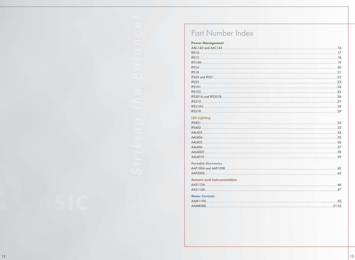
Part Number IndexPower ManagementAAC142 and AAC143 ................................................................................................................................................ 16IPS10 .............................................................................................................................................................................. 17IPS15 .............................................................................................................................................................................. 18IPS15H ........................................................................................................................................................................... 19IPS16 .............................................................................................................................................................................. 20IPS18 .............................................................................................................................................................................. 21IPS20 and IPS21 ........................................................................................................................................................... 22IPS25 .............................................................................................................................................................................. 23IPS101 ........................................................................................................................................................................... 24IPS102 ........................................................................................................................................................................... 25IPS201A and IPS201B .................................................................................................................................................. 26IPS315 ........................................................................................................................................................................... 27IPS315H ......................................................................................................................................................................... 28IPS318 ........................................................................................................................................................................... 29
LED LightingIPS401 ........................................................................................................................................................................... 32IPS402 ........................................................................................................................................................................... 33AAL403 .......................................................................................................................................................................... 34AAL404 .......................................................................................................................................................................... 35AAL405 .......................................................................................................................................................................... 36AAL406 .......................................................................................................................................................................... 37AAL4002 ....................................................................................................................................................................... 38AAL4010 ....................................................................................................................................................................... 39
Portable ElectronicsAAP109A and AAP109B ............................................................................................................................................. 42AAP200X ....................................................................................................................................................................... 43
Sensors and InstrumentationAAS112A ...................................................................................................................................................................... 46AAS114A ...................................................................................................................................................................... 47
Motor ControlsAAM119A ..................................................................................................................................................................... 50AAM858A ............................................................................................................................................................... 51-52

Power ManagementAAI has developed a strong expertise in Power Management and has specialized in the development and production of controllers for Switch Mode Power Supplies and Feedback and Support ICs. Newer part numbers will follow the AAI Part Numbering Convention, while the IN-PLUG® brand will continue to be associated with the existing Power Management and LED Lighting series of products. These products are supported for customization.
PWM ControlAAI’s PWM Control products feature Flyback, PFC, and Push-Pull/Resonant controllers, for minimum cost and maximum effi ciency SMPS ranging from a few watts to 1000W +
• Operating from any source ranging from 12VDC to 300VAC+• Low component count• Built-in overload protection/overvoltage• High-effi ciency >95%, High PFC >99% • ULTRA-GREEN (very low standby power when SMPS not loaded)
There is also a series of the PWM Controllers tailored for lower Vcc operation specifi cally intended for Automotive and other direct feedback applications. This series of IPS3XX and AAC3XX products feature:
• Min. VCC 7.2V • Up to 100% duty cycle for Buck, Boost and SEPIC simple topologies • Direct feeback and Isolated feedback• Frequency adjutable to up to 400Khz for EMI control and small magnetics• Automotive temperature range (-40° C to +125° C)
PWM Control Part Numbering• Flyback: IPS1X and AAC1XX /AACXXXX Series • PFC: IPS10X and AAC1XX /AACXXXX Series• Push-Pull: IPS20X and AAC2XXX Series• Automotive: IPS31X and AAC3XXX Series
Feedback and SupportThe IN-PLUG® Feedback and Support ICs feature three versions with different sense voltage levels and reference voltage characteristics. Each allows for implementation of a separate regulation vs. limiting function.
Feedback and Support Part Numbering• Feedback: IPS2X and AAF2X Series
Power Management Product Roadmap
Nov Dec Jan Feb Mar Apr May Jun Jul Aug Sep Oct Nov2007 2008
1514
IPS16 Offl ine SMPS Controllerwith Synchronization
IPS102 CriticalConduction Mode PFC
IPS201A and IPS201B Push-Pull Controllers
AAC142 Current Mode Controller
AAC143 Current Mode Controller
PRELIMINARY: Please consult the introductory section write-up Product Roadmap for information on timing of product introduction.
VCCOPTO
D
GNDRBIAS
ISENSE
PWM
ENBDRIVER
GATEFILTER
CURRENT LIMITING
REF1SHUNT
BandgapReferenceREGULATOR
REF2
COMPARATORS
OSCILLATOR
-+
R
S
Q-+
UnderVoltageLockout
ThermalShutdown
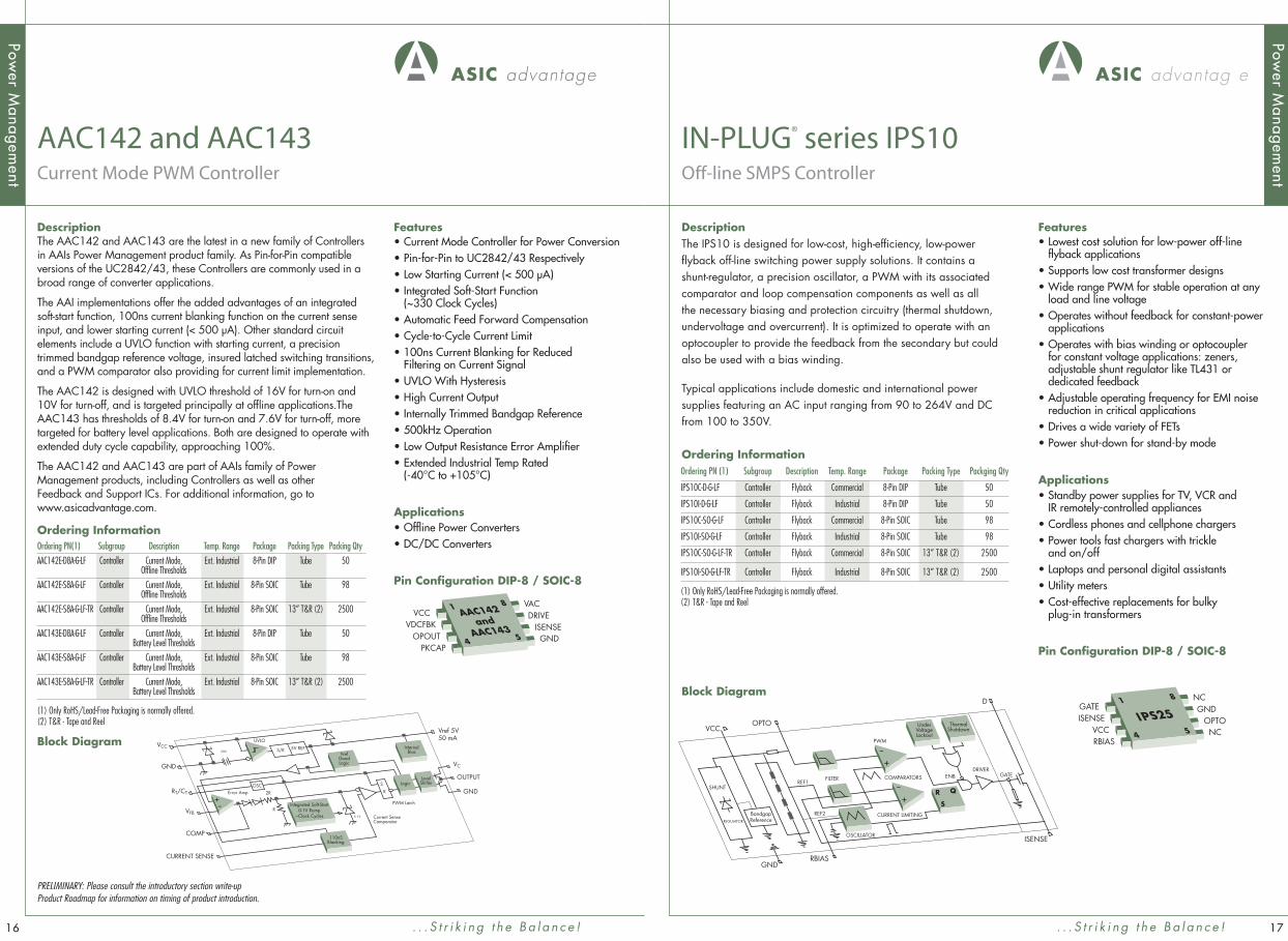
DescriptionThe IPS10 is designed for low-cost, high-effi ciency, low-power fl yback off-line switching power supply solutions. It contains a shunt-regulator, a precision oscillator, a PWM with its associated comparator and loop compensation components as well as all the necessary biasing and protection circuitry (thermal shutdown, undervoltage and overcurrent). It is optimized to operate with an optocoupler to provide the feedback from the secondary but could also be used with a bias winding.
Typical applications include domestic and international power supplies featuring an AC input ranging from 90 to 264V and DC from 100 to 350V.
Block Diagram
IN-PLUG® series IPS10 Off-line SMPS Controller
Features• Lowest cost solution for low-power off-line
fl yback applications• Supports low cost transformer designs• Wide range PWM for stable operation at any
load and line voltage• Operates without feedback for constant-power
applications• Operates with bias winding or optocoupler
for constant voltage applications: zeners, adjustable shunt regulator like TL431 or dedicated feedback
• Adjustable operating frequency for EMI noise reduction in critical applications
• Drives a wide variety of FETs• Power shut-down for stand-by mode
Applications• Standby power supplies for TV, VCR and
IR remotely-controlled appliances• Cordless phones and cellphone chargers• Power tools fast chargers with trickle
and on/off • Laptops and personal digital assistants• Utility meters• Cost-effective replacements for bulky
plug-in transformers
Pin Confi guration DIP-8 / SOIC-8
. . . S t r i k i n g t h e B a l a n c e !
IPS251
4
8
5
GATEISENSE
VCCRBIAS
NCGND
OPTONC
Ordering InformationOrdering PN (1) Subgroup Description Temp. Range Package Packing Type Packging Qty
IPS10C-D-G-LF Controller Flyback Commercial 8-Pin DIP Tube 50
IPS10I-D-G-LF Controller Flyback Industrial 8-Pin DIP Tube 50
IPS10C-SO-G-LF Controller Flyback Commercial 8-Pin SOIC Tube 98
IPS10I-SO-G-LF Controller Flyback Industrial 8-Pin SOIC Tube 98
IPS10C-SO-G-LF-TR Controller Flyback Commercial 8-Pin SOIC 13” T&R (2) 2500
IPS10I-SO-G-LF-TR Controller Flyback Industrial 8-Pin SOIC 13” T&R (2) 2500
(1) Only RoHS/Lead-Free Packaging is normally offered. (2) T&R - Tape and Reel
CURRENT SENSE
Current SenseComparator
Error Amp
UVLO
R
2R
PWM Latch
COMP
VFB
RT/CT
VCGND
GND
VCC
Vref 5V50 mA
OUTPUT
InternalBias
LogicLevelShifter
VrefGoodLogic
S/R 5V REF
Integrated Soft-Start0-1V Ramp
~Clock Cycles
-+
110nSBlanking
5.1V
20V
S
ROSC
DescriptionThe AAC142 and AAC143 are the latest in a new family of Controllers in AAIs Power Management product family. As Pin-for-Pin compatible versions of the UC2842/43, these Controllers are commonly used in a broad range of converter applications.
The AAI implementations offer the added advantages of an integrated soft-start function, 100ns current blanking function on the current sense input, and lower starting current (< 500 µA). Other standard circuit elements include a UVLO function with starting current, a precision trimmed bandgap reference voltage, insured latched switching transitions, and a PWM comparator also providing for current limit implementation.
The AAC142 is designed with UVLO threshold of 16V for turn-on and 10V for turn-off, and is targeted principally at offl ine applications.The AAC143 has thresholds of 8.4V for turn-on and 7.6V for turn-off, more targeted for battery level applications. Both are designed to operate with extended duty cycle capability, approaching 100%.
The AAC142 and AAC143 are part of AAIs family of Power Management products, including Controllers as well as other Feedback and Support ICs. For additional information, go to www.asicadvantage.com.
Ordering Information
Block Diagram
AAC142 and AAC143 Current Mode PWM Controller
Features• Current Mode Controller for Power Conversion• Pin-for-Pin to UC2842/43 Respectively• Low Starting Current (< 500 µA)• Integrated Soft-Start Function
(~330 Clock Cycles)• Automatic Feed Forward Compensation• Cycle-to-Cycle Current Limit• 100ns Current Blanking for Reduced
Filtering on Current Signal• UVLO With Hysteresis• High Current Output• Internally Trimmed Bandgap Reference• 500kHz Operation• Low Output Resistance Error Amplifi er• Extended Industrial Temp Rated
(-40°C to +105°C)
Applications• Offl ine Power Converters• DC/DC Converters
Pin Confi guration DIP-8 / SOIC-8
. . . S t r i k i n g t h e B a l a n c e !
AAC142and
AAC143
1
4
8
5
VCCVDCFBK
OPOUTPKCAP
VACDRIVE
ISENSEGND
Ordering PN(1) Subgroup Description Temp. Range Package Packing Type Packing Qty
AAC142E-D8A-G-LF Controller Current Mode, Ext. Industrial 8-Pin DIP Tube 50 Offl ine Thresholds
AAC142E-S8A-G-LF Controller Current Mode, Ext. Industrial 8-Pin SOIC Tube 98 Offl ine Thresholds
AAC142E-S8A-G-LF-TR Controller Current Mode, Ext. Industrial 8-Pin SOIC 13” T&R (2) 2500 Offl ine Thresholds
AAC143E-D8A-G-LF Controller Current Mode, Ext. Industrial 8-Pin DIP Tube 50 Battery Level Thresholds
AAC143E-S8A-G-LF Controller Current Mode, Ext. Industrial 8-Pin SOIC Tube 98 Battery Level Thresholds
AAC143E-S8A-G-LF-TR Controller Current Mode, Ext. Industrial 8-Pin SOIC 13” T&R (2) 2500 Battery Level Thresholds
(1) Only RoHS/Lead-Free Packaging is normally offered.(2) T&R - Tape and Reel
1716
Power M
anagement
Power M
anagement

VCCOPTO
GNDRBIAS
NDRIVEISENSE
SOFT START
REF1
SHUNT
BandgapReferenceREGULATOR
REF2
VCC
REF3
COMPARATORS
CURRENTLIMITING GND
OSCILLATOR
PWM
ENB
PDRIVE
OVERV
FILTER
-+
R
S
Q-+
ENB
UnderVoltageLockout
OverVoltageLockout
ThermalShutdown
DescriptionThe IN-PLUG IPS15 is an enhanced off-line switcher version of the IPS10. It includes additional features such as soft start and over-voltage limiting. Like the IPS10, the IPS15 was designed for low-cost, high-effi ciency, low-power fl yback off-line switching power supplies. It contains a shunt-regulator, a precision oscillator, a PWM with its associated comparator and loop compensation components as well as all the necessary biasing and protection circuitry (thermal shutdown, under-voltage, over-voltage and over-current).
Block Diagram
IN-PLUG® series IPS15Enhanced Off-line SMPS Controller
Features• Low cost solution for low-power off-line
fl yback applications• Simple, less critical, lower cost transformer• Wide range PWM for stable operation at any
load and line voltage• Suitable for constant-power applications• Operates with optocoupler or bias winding for
constant voltage applications • Power shut-down for stand-by modes• Cycle-to-cycle over-current protection• Under-voltage and over-voltage protection
Applications• Standby power supplies for TV, VCR and
IR remotely-controlled appliances• Cordless phones and cellphone chargers• Power tools fast chargers with trickle
and on/off • Laptops and personal digital assistants• Utility meters• Replacements for bulky plug-in transformers
Pin Confi guration DIP-8 / SOIC-8
Power M
anagement
. . . S t r i k i n g t h e B a l a n c e !
IPS151
4
8
5
PDRIVEISENSE
VCCRBIAS
NDRIVEGND
OPTOOVERV
Ordering InformationOrdering PN (1) Subgroup Description Temp. Range Package Packing Type Packging Qty
IPS15C-D-G-LF Controller Flyback + OVP + SS Commercial 8-Pin DIP Tube 50
IPS15I-D-G-LF Controller Flyback + OVP + SS Industrial 8-Pin DIP Tube 50
IPS15C-SO-G-LF Controller Flyback + OVP + SS Commercial 8-Pin SOIC Tube 98
IPS15I-SO-G-LF Controller Flyback + OVP + SS Industrial 8-Pin SOIC Tube 98
IPS15C-SO-G-LF-TR Controller Flyback + OVP + SS Commercial 8-Pin SOIC 13” T&R (2) 2500
IPS15I-SO-G-LF-TR Controller Flyback + OVP + SS Industrial 8-Pin SOIC 13” T&R (2) 2500
(1) Only RoHS/Lead-Free Packaging is normally offered. (2) T&R - Tape and Reel
1918
VCCOPTO
GNDRBIAS
NDRIVEISENSE
SOFT START
REF1
SHUNT
BandgapReferenceREGULATOR
REF2
VCC
REF3
COMPARATORS
CURRENTLIMITING GND
OSCILLATOR
PWM
ENB
PDRIVEOVERV
FILTER
-+
R
S
Q-+
ENB
UnderVoltageLockout
OverVoltageLockout
ThermalShutdown
DescriptionThe IN-PLUG IPS15H is an enhanced off-line switcher version of the IPS10. It includes additional features such as soft start and over-voltage limiting. Like the IPS10, the IPS15H was designed for low-cost, high-effi ciency, low-power fl yback off-line switching power supplies. It contains a shunt-regulator, a precision oscillator, a PWM with its associated comparator and loop compensation components as well as all the necessary biasing and protection circuitry (thermal shutdown, under-voltage, over-voltage and over-current).
Block Diagram
IN-PLUG® series IPS15HEnhanced Hiccup Off-line SMPS Controller
Features• Hiccup provides enhanced overload protection• Low cost solution for low-power off-line
fl yback applications• Simple, less critical, lower cost transformer• Wide range PWM for stable operation at any
load and line voltage• Suitable for constant-power applications• Operates with optocoupler or bias winding
for constant voltage applications • Power shut-down for stand-by modes• Cycle-to-cycle over-current protection• Under-voltage and over-voltage protection
Applications• Standby power supplies for TV, VCR and IR
remotely-controlled appliances• Cordless phones and cellphone chargers• Power tools fast chargers with trickle
and on/off • Laptops and personal digital assistants• Utility meters• Replacements for bulky plug-in transformers
Pin Confi guration DIP-8 / SOIC-8
. . . S t r i k i n g t h e B a l a n c e !
IPS15H1
4
8
5
PDRIVEISENSE
VCCRBIAS
NDRIVEGND
OPTOOVERV
Ordering InformationOrdering PN (1) Subgroup Description Temp. Range Package Packing Type Packging Qty
IPS15HC-D-G-LF Controller IPS15 + Hiccup OCP Commercial 8-Pin DIP Tube 50
IPS15HI-D-G-LF Controller IPS15 + Hiccup OCP Industrial 8-Pin DIP Tube 50
IPS15HC-SO-G-LF Controller IPS15 + Hiccup OCP Commercial 8-Pin SOIC Tube 98
IPS15HI-SO-G-LF Controller IPS15 + Hiccup OCP Industrial 8-Pin SOIC Tube 98
IPS15HC-SO-G-LF-TR Controller IPS15 + Hiccup OCP Commercial 8-Pin SOIC 13” T&R (2) 2500
IPS15HI-SO-G-LF-TR Controller IPS15 + Hiccup OCP Industrial 8-Pin SOIC 13” T&R (2) 2500
(1) Only RoHS/Lead-Free Packaging is normally offered. (2) T&R - Tape and Reel
Proprietary provision for reduction of power in hiccup state for over-current protection. Provisionally fi led, patent in process.
Power M
anagement

GNDRBIAS
OPTOVCC
NDRIVEISENSE
SOFT START
SHUNT
BandgapReference REGULATOR
REF2
REF3
VCC
REF1
COMPARATORS
CURRENTLIMITING GND
OSCILLATOR
SYNC
ENB
ENB
PDRIVE
FILTER
-+
-+
R
SQ
UnderVoltageLockout
ThermalShutdown
DescriptionThe IN-PLUG IPS16 is an enhanced off-line switcher version of the IPS10. It includes additional features such as soft start. Like theIPS10, the IPS16 was designed for low-cost, high-effi ciency, low-power fl yback off-line switching power supplies. It contains a shunt-regulator, a precision oscillator, a PWM with its associated comparator and loop compensation components as well as all the necessary biasing and protection circuitry (thermal shutdown, under-voltage and over-current).
Block Diagram
IN-PLUG® series IPS16 Enhanced Off-line SMPS Controller With Synchronization and Cycle-Skipping
Features• External oscillator synchronization for
display and other applications• Cycle-Skipping for minimal dissipation under
light-load conditions• Wide range PWM for stable operation at any
load and line voltage• Suitable for constant-power applications• Operates with optocoupler or bias winding
for constant voltage applications• Power shut-down for stand-by modes• Cycle-to-cycle over-current protection• Under-voltage
Applications• Standby power supplies for TV, VCR and
IR remotely-controlled appliances• Cordless phones and cellphone chargers• Power tools fast chargers with trickle
and on/off• Laptops and personal digital assistants.• Utility meters• Replacements for bulky plug-in transformers
Pin Confi guration DIP-8 / SOIC-8
Power M
anagement
. . . S t r i k i n g t h e B a l a n c e !
IPS161
4
8
5
PDRIVEISENSE
VCCRBIAS
NDRIVEGND
OPTOSYNC
Ordering InformationOrdering PN (1) Subgroup Description Temp. Range Package Packing Type Packging Qty
IPS16C-D-G-LF Controller IPS15 + Synch Input Commercial 8-Pin DIP Tube 50
IPS16I-D-G-LF Controller IPS15 + Synch Input Industrial 8-Pin DIP Tube 50
IPS16C-SO-G-LF Controller IPS15 + Synch Input Commercial 8-Pin SOIC Tube 98
IPS16I-SO-G-LF Controller IPS15 + Synch Input Industrial 8-Pin SOIC Tube 98
IPS16C-SO-G-LF-TR Controller IPS15 + Synch Input Commercial 8-Pin SOIC 13” T&R (2) 2500
IPS16I-SO-G-LF-TR Controller IPS15 + Synch Input Industrial 8-Pin SOIC 13” T&R (2) 2500
(1) Only RoHS/Lead-Free Packaging is normally offered. (2) T&R - Tape and Reel
Power M
anagement
VCCOPTO
GNDRBIAS
NDRIVEISENSE
SOFT START
REF1
SHUNT
BandgapReferenceREGULATOR
REF2
VCC
REF3
COMPARATORS
CURRENTLIMITING GND
OSCILLATOR
PWM
ENB
ENB
PDRIVEOVERV
FILTER
-+
R
S
Q-+
UnderVoltageLockout
OverVoltageLockout
ThermalShutdown
DescriptionThe IN-PLUG IPS18 is an enhanced off-line switcher version of the IPS10. It includes additional features such as soft start and over-voltage limiting. Like the IPS10, the IPS18 was designed for low-cost, high-effi ciency, low-power fl yback off-line switching power supplies. It contains a shunt-regulator, a precision oscillator, a PWM with its associated comparator and loop compensation components as well as all the necessary biasing and protection circuitry (thermal shutdown, under-voltage, over-voltage and over-current).
Block Diagram
IN-PLUG® series IPS18 Enhanced Off-line SMPS Controller With Hiccup and Cycle-Skipping
Features• Cycle-Skipping for minimal dissipation under
light-load conditions• Low cost solution for low-power off-line
fl yback applications• Wide range PWM for stable operation at any
load and line voltage• Suitable for constant-power applications• Operates with optocoupler or bias winding
for constant voltage applications
Applications• Standby power supplies for TV, VCR and IR
remotely-controlled appliances• Cordless phones and cellphone chargers• Power tools fast chargers with trickle
and on/off • Laptops and personal digital assistants• Utility meters• Replacements for bulky plug-in transformers
Pin Confi guration DIP-8 / SOIC-8
. . . S t r i k i n g t h e B a l a n c e !
IPS181
4
8
5
PDRIVEISENSE
VCCRBIAS
NDRIVEGND
OPTOOVERV
Ordering InformationOrdering PN (1) Subgroup Description Temp. Range Package Packing Type Packging Qty
IPS18C-D-G-LF Controller IPS15H + Cycle Skipping Commercial 8-Pin DIP Tube 50
IPS18I-D-G-LF Controller IPS15H + Cycle Skipping Industrial 8-Pin DIP Tube 50
IPS18C-SO-G-LF Controller IPS15H + Cycle Skipping Commercial 8-Pin SOIC Tube 98
IPS18I-SO-G-LF Controller IPS15H + Cycle Skipping Industrial 8-Pin SOIC Tube 98
IPS18C-SO-G-LF-TR Controller IPS15H + Cycle Skipping Commercial 8-Pin SOIC 13” T&R (2) 2500
IPS18I-SO-G-LF-TR Controller IPS15H + Cycle Skipping Industrial 8-Pin SOIC 13” T&R (2) 2500
(1) Only RoHS/Lead-Free Packaging is normally offered. (2) T&R - Tape and Reel
PRELIMINARY: Please consult the introductory section write-up Product Roadmap for information on timing of product introduction.
Proprietary provision for reduction of stand-by power. Provisionally fi led, patent in process. Proprietary provision for reduction of power in hiccup state for over-current protection. Provisionally fi led, patent in process.
2120

ICOMP
GND
VSENSE
OPTO
OUT (-)
VCOMP
IS
VCC
Trimmed 1.25VTemp. Stable
BandgapRegulator
4V ShuntRegulator
Trimmed Current Sensing
50mV PTAT 100mV
Temp. Stable
CurrentError
Amplifier
VoltageError
Amplifier
OPTOCOUPLERCurrent-Source
Control
DescriptionThe IPS20 and IPS21 are low-voltage current sensing feedback controllers used in switch mode power supplies to control load-side current and voltage. They have been designed to limit the power dissipated in the sensing circuitry for high output current applications that require current limiting. They both incorporate a 4V shunt regulator for maximum fl exibility to power the chip. The IPS20 and IPS21 only differ by the characteristics of the current sensing references.
The IPS20 incorporates a trimmed 50mV reference with a positive temperature coeffi cient which closely matches that of a PCB copper trace. This copper trace sensing method can be used inexpensively with very low associated power losses. The IPS21 incorporates a temperature compensated 100mV reference for more conventional resistors. Both controllers feature the same voltage regulator section with a trimmed temperature stable voltage reference of 1.19V.
Block Diagram
IN-PLUG® series IPS20 and IPS21 Feedback Controllers With Low Current Sense Voltage
Features• Dual precision regulators for SMPS voltage
and current control• Output currents up to 50A• Output voltage down to 1.2V• 50mV or 100mV current sensing voltage • 1.20V voltage reference• Operates with grounded optocoupler • 4V shunt regulator for VCC supply
Applications• Fast chargers for power tools and other
applications• Battery eliminators• Industrial and bench-type power supplies• Distributed power systems
Pin Confi guration DIP-8 / SOIC-8
Power M
anagement
. . . S t r i k i n g t h e B a l a n c e !
IPS20IPS21
1
4
8
5
VCCVS
VCOMPOPTO
GNDOUT (-)
ISICOMP
Ordering InformationOrdering PN (1) Subgroup Description Temp. Range Package Packing Type Packging Qty
IPS20C-D-G-LF Feedback V/I FB and Cntrl, 50mV Commercial 8-Pin DIP Tube 50 and Support Vsen, Tcu Comp Ref
IPS20I-D-G-LF Feedback V/I FB and Cntrl, 50mV Industrial 8-Pin DIP Tube 50 and Support Vsen, Tcu Comp Ref
IPS20C-SO-G-LF Feedback V/I FB and Cntrl, 50m Commercial 8-Pin SOIC Tube 98 and Support Vsen, Tcu Comp Ref
IPS20I-SO-G-LF Feedback V/I FB and Cntrl, 50m Industrial 8-Pin SOIC Tube 98 and Support Vsen, Tcu Comp Ref
IPS20C-SO-G-LF-TR Feedback V/I FB and Cntrl, 50mV Commercial 8-Pin SOIC 13” T&R (2) 2500 and Support Vsen, Tcu Comp Ref
IPS20I-SO-G-LF-TR Feedback V/I FB and Cntrl, 50mV Industrial 8-Pin SOIC 13” T&R (2) 2500 and Support Vsen, Tcu Comp Ref
IPS21C-D-G-LF Feedback V/I FB and Cntrl, Commercial 8-Pin DIP Tube 50 and Support 100mV Vsen
IPS21I-D-G-LF Feedback V/I FB and Cntrl, Industrial 8-Pin DIP Tube 50 and Support 100mV Vsen
IPS21C-SO-G-LF Feedback V/I FB and Cntrl,n Commercial 8-Pin SOIC Tube 98 and Support 100mV Vsen
IPS21I-SO-G-LF Feedback V/I FB and Cntrl, Industrial 8-Pin SOIC Tube 98 and Support 100mV Vsen
IPS21C-SO-G-LF-TR Feedback V/I FB and Cntrl, Commercial 8-Pin SOIC 13” T&R (2) 2500 and Support 100mV Vsen
IPS21I-SO-G-LF-TR Feedback V/I FB and Cntrl, Industrial 8-Pin SOIC 13” T&R (2) 2500 and Support 100mV Vsen
(1) Only RoHS/Lead-Free Packaging is normally offered.(2) T&R - Tape and Reel
Power M
anagement
2322
COMPIGND
VSENSE
OPTO
ISENSE NC
COMPV
VCC
Trimmed2.60V
BandgapRegulator
Trimmed 1.33VBandgap Regulator
1.2K
400K
VCC VCC
-+
-+
CurrentError
Amplifier
VoltageError
Amplifier
Current-SourceControl
DescriptionThe IPS25 is a low-voltage current sensing feedback controller used in switch mode power supplies to control load-side current and voltage. It uses a series regulator off the VCC pin for maximum fl exibility to power the chip. The IPS25 incorporates a trimmed 1.33V reference for current sensing. The voltage sensing section uses a trimmed temperature stable voltage reference of 2.6V.
Block Diagram
IN-PLUG® series IPS25 Feedback Controller With Low Operating Voltage
Features• Dual precision regulators for SMPS voltage
and current control• Output currents up to 0.8A• Output voltage down to 2.6V• Operates with grounded optocoupler • Series regulator for VCC supply up to 30 volts
Applications• Fast chargers for power tools and other
applications• Battery eliminators• Industrial and bench-type power supplies• Distributed power systems
Pin Confi guration DIP-8 / SOIC-8
. . . S t r i k i n g t h e B a l a n c e !
IPS251
4
8
5
VCCVSENSECOMPV
OPTO
ISENSENC
COMPIGND
Ordering InformationOrdering PN(1) Subgroup Description Temp. Range Package Packing Type Packing Qty
IPS25C-D-G-LF Feedback and Support V/I FB and Cntrl, 1.3V Vsen Commercial 8-Pin DIP Tube 50
IPS25I-D-G-LF Feedback and Support V/I FB and Cntrl, 1.3V Vsen Industrial 8-Pin DIP Tube 50
IPS25C-SO-G-LF Feedback and Support V/I FB and Cntrl, 1.3V Vsen Commercial 8-Pin SOIC Tube 98
IPS25I-SO-G-LF Feedback and Support V/I FB and Cntrl, 1.3V Vsen Industrial 8-Pin SOIC Tube 98
IPS25C-SO-G-LF-TR Feedback and Support V/I FB and Cntrl, 1.3V Vsen Commercial 8-Pin SOIC 13” T&R (2) 2500
IPS25I-SO-G-LF-TR Feedback and Support V/I FB and Cntrl, 1.3V Vsen Industrial 8-Pin SOIC 13” T&R (2) 2500
(1) Only RoHS/Lead-Free Packaging is normally offered.(2) T&R - Tape and Reel

INTERNALBIAS
VCC VDCFBK
RMSCAPCOMPV
GND
DRIVE VAC
ISENSE
CONVERTERS
DRIVER
TrimmedBandgap
REGULATOR
INTERNALBIAS
MIRROR
I AC
I ErrorIN1 IN2
IN3
OUT
I RMS
REF
VON
VOFF
OFF
ON
&
-+
-+
-+
ControlLogic
Multiplier
V to IRMS
2.06V
Under VoltageLockout
Block Diagram
IN-PLUG® series IPS101 Power Factor Correction Controller
Features• Capable of driving a broad range
of power MOSFETs• Uses a self-oscillating topology good to
300kHz• Voltage error amplifi er with provision
for loop stability compensation• High effi ciency over 96%
(in optimized designs)• Minimum external component count• 3-input current-mode multiplier ensures good
performance at any line voltage or load• Under-voltage protection. Cycle-by-cycle
current limiting. Thermal shutdown
Applications• SMPS• Electronic ballast
Pin Confi guration DIP-8 / SOIC-8
Power M
anagement
. . . S t r i k i n g t h e B a l a n c e !
IPS1011
4
8
5
VCCVDCFBK
COMPVPKCAP
VACDRIVE
ISENSEGND
DescriptionThe IN-PLUG IPS101 is a primary-side switching controller which provides high performance active power factor correction (PFC). The PFC circuitry forces the SMPS to draw a current proportional to the instant AC line voltage in order to charge a storage capacitor thus resulting in excellent power factor and low-line harmonics generation. The output of the PFC is a regulated voltage which slightly exceeds the peak line voltage.
Ordering InformationOrdering PN(1) Subgroup Description Temp. Range Package Packing Type Packing Qty
IPS101C-D-G-LF Controller PFC, Continuous, Fixed Freq Commercial 8-Pin DIP Tube 50
IPS101I-D-G-LF Controller PFC, Continuous, Fixed Freq Industrial 8-Pin DIP Tube 50
IPS101C-SO-G-LF Controller PFC, Continuous, Fixed Freq Commercial 8-Pin SOIC Tube 98
IPS101I-SO-G-LF Controller PFC, Continuous, Fixed Freq Industrial 8-Pin SOIC Tube 98
IPS101C-SO-G-LF-TR Controller PFC, Continuous, Fixed Freq Commercial 8-Pin SOIC 13” T&R (2) 2500
IPS101I-SO-G-LF-TR Controller PFC, Continuous, Fixed Freq Industrial 8-Pin SOIC 13” T&R (2) 2500
(1) Only RoHS/Lead-Free Packaging is normally offered.(2) T&R - Tape and Reel
Power M
anagement
2524
DescriptionThe IN-PLUG IPS102 is a primary-side switching controller which provides high performance active power factor correction (PFC). The PFC circuitry forces the SMPS to draw a current proportional to the instant AC line voltage in order to charge a storage capacitor thus resulting in excellent power factor and low line harmonics generation. The output of the PFC is a regulated voltage which slightly exceeds the peak line voltage.
Ordering Information
Block Diagram
IN-PLUG® series IPS102Critical Conduction Power Factor Correction Controller
Features• Capable of driving a broad range
of power MOSFETs• Uses a self-oscillating topology
good to 300kHz• Voltage error amplifi er with provision
for loop stability compensation• High effi ciency over 96%
(in optimized designs)• Minimum external component count• 3-input current-mode multiplier ensures good
performance at any line voltage or load• Under-voltage protection. Cycle-by-cycle
current limiting. Thermal shutdown
Applications• SMPS• Electronic ballast
Pin Confi guration DIP-8 / SOIC-8
. . . S t r i k i n g t h e B a l a n c e !
VCC VDCFBK
RMSCAPCOMPV
GND
DRIVE VAC
ISENSE
CONVERTERS
DRIVER
TrimmedBandgap
REGULATOR
INTERNALBIAS
INTERNALBIAS
2.06V MIRROR
I AC
I ErrorIN1 IN2
IN3
OUT
I RMS
REF
VON
VOFF
OFF
ON
&
-+
-+
-+
Under VoltageLockout
ControlLogic
Multiplier
V to IRMS
20m Vref
IPS1021
4
8
5
VCCVDCFBK
COMPVPKCAP
VACDRIVE
ISENSEGND
PRELIMINARY: Please consult the introductory section write-up Product Roadmap for information on timing of product introduction.
Ordering PN(1) Subgroup Description Temp. Range Package Packing Type Packing Qty
IPS102 C-D-G-LF Controller PFC, Critical Commercial 8-Pin DIP Tube 50 Conduction Mode
IPS102 I-D-G-LF Controller PFC, Critical Industrial 8-Pin DIP Tube 50 Conduction Mode
IPS102 C-SO-G-LF Controller PFC, Critical Commercial 8-Pin SOIC Tube 98 Conduction Mode
IPS102 I-SO-G-LF Controller PFC, Critical Industrial 8-Pin SOIC Tube 98 Conduction Mode
IPS102 C-SO-G-LF-TR Controller PFC, Critical Commercial 8-Pin SOIC 13” T&R (2) 2500 Conduction Mode
IPS102 I-SO-G-LF-TR Controller PFC, Critical Industrial 8-Pin SOIC 13” T&R (2) 2500 Conduction Mode
(1) Only RoHS/Lead-Free Packaging is normally offered.(2) T&R - Tape and Reel
Power M
anagement
Power M
anagement
2726
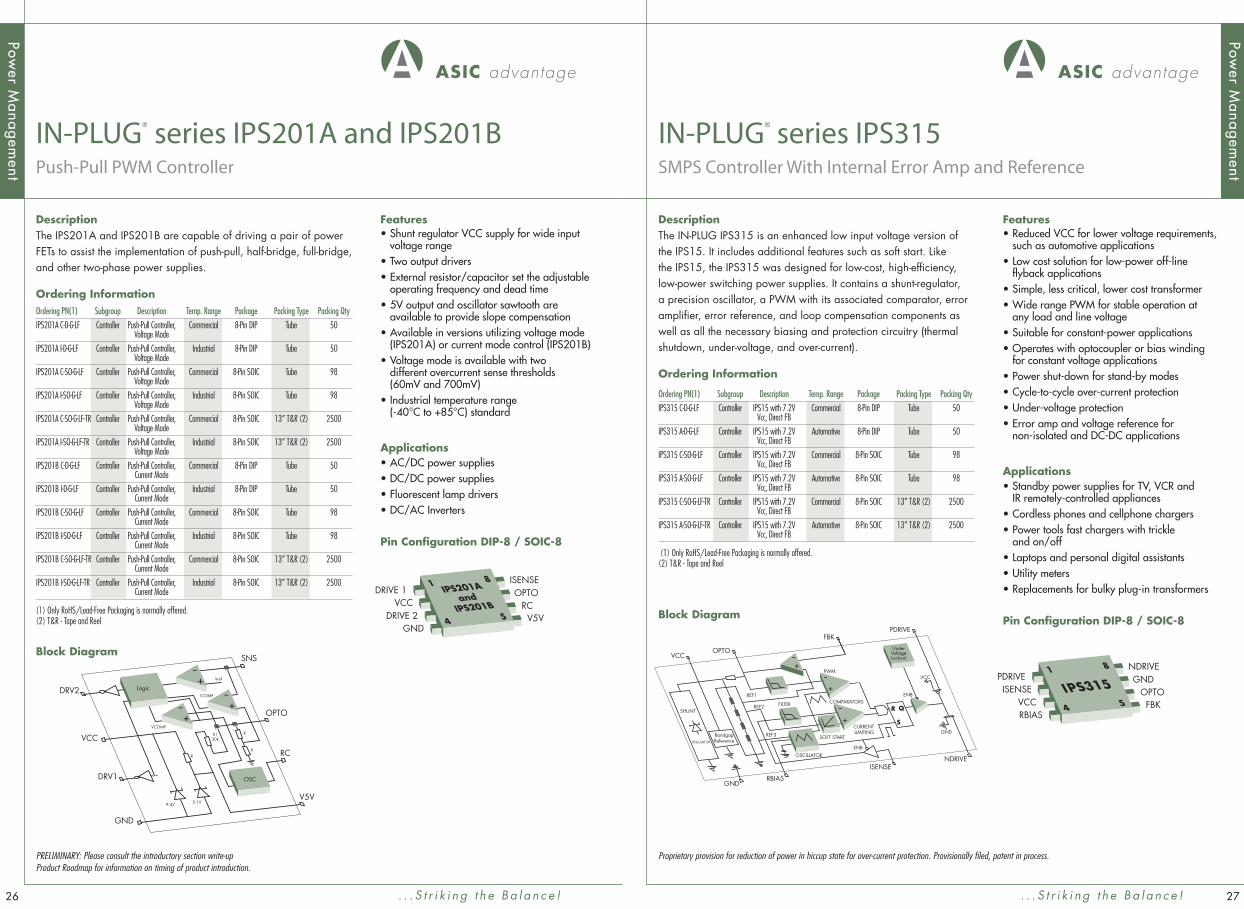
DescriptionThe IN-PLUG IPS315 is an enhanced low input voltage version of the IPS15. It includes additional features such as soft start. Like the IPS15, the IPS315 was designed for low-cost, high-effi ciency, low-power switching power supplies. It contains a shunt-regulator, a precision oscillator, a PWM with its associated comparator, error amplifi er, error reference, and loop compensation components as well as all the necessary biasing and protection circuitry (thermal shutdown, under-voltage, and over-current).
Ordering Information
Block Diagram
IN-PLUG® series IPS315 SMPS Controller With Internal Error Amp and Reference
Features• Reduced VCC for lower voltage requirements,
such as automotive applications• Low cost solution for low-power off-line
fl yback applications• Simple, less critical, lower cost transformer• Wide range PWM for stable operation at
any load and line voltage• Suitable for constant-power applications• Operates with optocoupler or bias winding
for constant voltage applications • Power shut-down for stand-by modes• Cycle-to-cycle over-current protection• Under-voltage protection• Error amp and voltage reference for
non-isolated and DC-DC applications
Applications• Standby power supplies for TV, VCR and
IR remotely-controlled appliances• Cordless phones and cellphone chargers• Power tools fast chargers with trickle
and on/off • Laptops and personal digital assistants• Utility meters• Replacements for bulky plug-in transformers
Pin Confi guration DIP-8 / SOIC-8
. . . S t r i k i n g t h e B a l a n c e !
VCCOPTO
GNDRBIAS
NDRIVEISENSE
SOFT START
REF1
SHUNT
BandgapReferenceREGULATOR
REF2
VCC
REF3
COMPARATORS
CURRENTLIMITING GND
OSCILLATOR
PWM
ENB
ENB
PDRIVEFBK
FILTER
-+
R
S
Q-+
UnderVoltageLockout-
+
IPS3151
4
8
5
PDRIVEISENSE
VCCRBIAS
NDRIVEGND
OPTOFBK
DescriptionThe IPS201A and IPS201B are capable of driving a pair of power FETs to assist the implementation of push-pull, half-bridge, full-bridge, and other two-phase power supplies.
Ordering Information
IN-PLUG® series IPS201A and IPS201BPush-Pull PWM Controller
Features• Shunt regulator VCC supply for wide input
voltage range• Two output drivers• External resistor/capacitor set the adjustable
operating frequency and dead time• 5V output and oscillator sawtooth are
available to provide slope compensation• Available in versions utilizing voltage mode
(IPS201A) or current mode control (IPS201B)• Voltage mode is available with two
different overcurrent sense thresholds (60mV and 700mV)
• Industrial temperature range(-40°C to +85°C) standard
Applications• AC/DC power supplies• DC/DC power supplies• Fluorescent lamp drivers• DC/AC Inverters
Pin Confi guration DIP-8 / SOIC-8
. . . S t r i k i n g t h e B a l a n c e !
VCC
GND
DRV1
SNS
OPTO
RC
V5V
DRV2
9.4V
R
R
R
Vref
VCOMP
ICOMP
R130k
5.1V
-+
-+-
+
OSC
Logic
IPS201A and
IPS201B
1
4
8
5
DRIVE 1VCC
DRIVE 2GND
ISENSEOPTO
RCV5V
PRELIMINARY: Please consult the introductory section write-up Product Roadmap for information on timing of product introduction.
Ordering PN(1) Subgroup Description Temp. Range Package Packing Type Packing Qty
IPS315 C-D-G-LF Controller IPS15 with 7.2V Commercial 8-Pin DIP Tube 50 Vcc, Direct FB
IPS315 A-D-G-LF Controller IPS15 with 7.2V Automotive 8-Pin DIP Tube 50 Vcc, Direct FB
IPS315 C-SO-G-LF Controller IPS15 with 7.2V Commercial 8-Pin SOIC Tube 98 Vcc, Direct FB
IPS315 A-SO-G-LF Controller IPS15 with 7.2V Automotive 8-Pin SOIC Tube 98 Vcc, Direct FB
IPS315 C-SO-G-LF-TR Controller IPS15 with 7.2V Commercial 8-Pin SOIC 13” T&R (2) 2500 Vcc, Direct FB
IPS315 A-SO-G-LF-TR Controller IPS15 with 7.2V Automotive 8-Pin SOIC 13” T&R (2) 2500 Vcc, Direct FB
(1) Only RoHS/Lead-Free Packaging is normally offered.(2) T&R - Tape and Reel
Ordering PN(1) Subgroup Description Temp. Range Package Packing Type Packing Qty
IPS201A C-D-G-LF Controller Push-Pull Controller, Commercial 8-Pin DIP Tube 50 Voltage Mode
IPS201A I-D-G-LF Controller Push-Pull Controller, Industrial 8-Pin DIP Tube 50 Voltage Mode
IPS201A C-SO-G-LF Controller Push-Pull Controller, Commercial 8-Pin SOIC Tube 98 Voltage Mode
IPS201A I-SO-G-LF Controller Push-Pull Controller, Industrial 8-Pin SOIC Tube 98 Voltage Mode
IPS201A C-SO-G-LF-TR Controller Push-Pull Controller, Commercial 8-Pin SOIC 13” T&R (2) 2500 Voltage Mode
IPS201A I-SO-G-LF-TR Controller Push-Pull Controller, Industrial 8-Pin SOIC 13” T&R (2) 2500 Voltage Mode
IPS201B C-D-G-LF Controller Push-Pull Controller, Commercial 8-Pin DIP Tube 50 Current Mode
IPS201B I-D-G-LF Controller Push-Pull Controller, Industrial 8-Pin DIP Tube 50 Current Mode
IPS201B C-SO-G-LF Controller Push-Pull Controller, Commercial 8-Pin SOIC Tube 98 Current Mode
IPS201B I-SO-G-LF Controller Push-Pull Controller, Industrial 8-Pin SOIC Tube 98 Current Mode
IPS201B C-SO-G-LF-TR Controller Push-Pull Controller, Commercial 8-Pin SOIC 13” T&R (2) 2500 Current Mode
IPS201B I-SO-G-LF-TR Controller Push-Pull Controller, Industrial 8-Pin SOIC 13” T&R (2) 2500 Current Mode
(1) Only RoHS/Lead-Free Packaging is normally offered.(2) T&R - Tape and Reel
Block Diagram
Proprietary provision for reduction of power in hiccup state for over-current protection. Provisionally fi led, patent in process.

Power M
anagement
DescriptionThe IN-PLUG IPS315H is an enhanced low input voltage version of the IPS15H. It includes additional features such as soft start. Like the IPS15H, the IPS315H was designed for low-cost, high-effi ciency, low-power switching power supplies. It contains a shunt-regulator, a precision oscillator, a PWM with its associated comparator and loop compensation components, an error amplifi er, an error amplifi er reference, as well as all the necessary biasing and protection circuitry (thermal shutdown, under-voltage, and over-current).
Ordering Information
Block Diagram
IN-PLUG® series IPS315HSMPS Controller With Error Amp, Reference, and Hiccup
Features• Hiccup mode for sustained
overload conditions• Low cost solution for low-power off-line
fl yback applications• Simple, less critical, lower cost transformer• Wide range PWM for stable operation at
any load and line voltage• Suitable for constant-power applications.• Operates with optocoupler or bias winding
for constant voltage applications • Power shut-down for stand-by modes• Cycle-to-cycle over-current protection• Under-voltage protection• Error amp and voltage reference for
non-isolated and DC-DC applications• Reduced VCC required for automotive
applications
Applications• Standby power supplies for TV, VCR
and IR remotely-controlled appliances• Cordless phones and cellphone chargers• Power tools fast chargers with trickle
and on/off• Laptops and personal digital assistants• Utility meters• Replacements for bulky plug-in transformers
Pin Confi guration DIP-8 / SOIC-8
Power M
anagement
. . . S t r i k i n g t h e B a l a n c e !
VCCOPTO
GNDRBIAS
NDRIVEISENSE
SOFT START
REF1
SHUNT
BandgapReferenceREGULATOR
REF2
VCC
REF3
COMPARATORS
CURRENTLIMITING GND
OSCILLATOR
PWM
ENB
ENB
PDRIVEFBK
FILTER
-
-
+
+
R
S
Q-+
UnderVoltageLockout
IPS315H1
4
8
5
PDRIVEISENSE
VCCRBIAS
NDRIVEGND
OPTOFBK
2928
DescriptionThe IN-PLUG IPS318 is an enhanced low input voltage version of the IPS18. It includes additional features such as soft start. Like the IPS18, the IPS318 was designed for low-cost, high-effi ciency, low-power switching power supplies. It contains a shunt-regulator, a precision oscillator, a PWM with its associated comparator, error amplifi er, error reference, and loop compensation components as well as all the necessary biasing and protection circuitry (thermal shutdown, under-voltage, and over-current).
Ordering Information
Block Diagram
IN-PLUG® series IPS318SMPS Controller With Error Amp Reference, Hiccup, and Cycle-Skip
Features• Cycle-Skipping for minimal dissipation under
no-load conditions• Low cost solution for low-power off-line
fl yback applications• Simple, less critical, lower cost transformer• Wide range PWM for stable operation at any
load and line voltage• Suitable for constant-power applications• Operates with optocoupler or bias winding
for constant voltage applications • Power shut-down for stand-by modes• Cycle-to-cycle over-current protection• Under-voltage protection• Error amp and voltage reference for
non-isolated and DC-DC applications• Reduced VCC for lower voltage requirements,
such as automotive applications• Hiccup mode for sustained
overload conditions• Cycle-skip for no-load conditions
Applications• Standby power supplies for TV, VCR
and IR remotely-controlled appliances• Cordless phones and cellphone chargers• Power tools fast chargers with trickle
and on/off • Laptops and personal digital assistants• Utility meters• Replacements for bulky plug-in transformers
Pin Confi guration DIP-8 / SOIC-8
. . . S t r i k i n g t h e B a l a n c e !
VCCOPTO
GNDRBIAS
NDRIVEISENSE
SOFT START
REF1
SHUNT
BandgapReferenceREGULATOR
REF2
VCC
VCCSW
REF3
COMPARATORS
CURRENTLIMITING
OSCILLATOR
PWM
ENB
ENB
PDRIVEFBK
FILTER
-
-
+
+
R
S
Q-+
UnderVoltageLockoutCycle
Skipping
HiccupControl
IPS3181
4
8
5
PDRIVEISENSE
VCCRBIAS
NDRIVEGND
OPTOFBK
Ordering PN(1) Subgroup Description Temp. Range Package Packing Type Packing Qty
IPS318 C-D-G-LF Controller IPS315H Commercial 8-Pin DIP Tube 50 + Cycle Skipping
IPS318 A-D-G-LF Controller IPS315H Automotive 8-Pin DIP Tube 50 + Cycle Skipping
IPS318 C-SO-G-LF Controller IPS315H Commercial 8-Pin SOIC Tube 98 + Cycle Skipping
IPS318 A-SO-G-LF Controller IPS315H Automotive 8-Pin SOIC Tube 98 + Cycle Skipping
IPS318 C-SO-G-LF-TR Controller IPS315H Commercial 8-Pin SOIC 13” T&R (2) 2500 + Cycle Skipping
IPS318 A-SO-G-LF-TR Controller IPS315H Automotive 8-Pin SOIC 13” T&R (2) 2500 + Cycle Skipping
(1) Only RoHS/Lead-Free Packaging is normally offered.(2) T&R - Tape and Reel
Ordering PN(1) Subgroup Description Temp. Range Package Packing Type Packing Qty
IPS315H C-D-G-LF Controller IPS15 with 7.2V Vcc, Commercial 8-Pin DIP Tube 50 Direct FB and Hiccup OCP
IPS315H A-D-G-LF Controller IPS15 with 7.2V Vcc, Automotive 8-Pin DIP Tube 50 Vcc, Direct FB and Hiccup OCP
IPS315H C-SO-G-LF Controller IPS15 with 7.2V Vcc, Commercial 8-Pin SOIC Tube 98 Vcc, Direct FB and Hiccup OCP
IPS315H A-SO-G-LF Controller IPS15 with 7.2V Automotive 8-Pin SOIC Tube 98 Vcc, Direct FB and Hiccup OCP
IPS315H C-SO-G-LF-TR Controller IPS15 with 7.2V Commercial 8-Pin SOIC 13” T&R (2) 2500 Vcc, Direct FB and Hiccup OCP
IPS315H A-SO-G-LF-TR Controller IPS15 with 7.2V Automotive 8-Pin SOIC 13” T&R (2) 2500 Vcc, Direct FB and Hiccup OCP
(1) Only RoHS/Lead-Free Packaging is normally offered.(2) T&R - Tape and Reel
Proprietary provision for reduction of stand-by power. Provisionally fi led, patent in process. Proprietary provision for reduction of power in hiccup state for over-current protection. Provisionally fi led, patent in process.
Proprietary provision for reduction of power in hiccup state for over-current protection. Provisionally fi led, patent in process.

LED LightingAAI has developed a thorough understanding of the unique requirements for driving and controlling LEDs.LEDs are rapidly emerging as the leading choice for lighting purposes in an environment of ever rising environmental concerns over energy and effi ciency. The unique requirements for proper implementation of LED lighting solutions is considered to be a focus market in AAIs new portfolio of standard products. As with our Power Management products, some of AAIs original LED Lighting products will continue to be offered under the original IN-PLUG® Part Number Convention, while newer parts will follow the AAI Part Numbering Convention.The IN-PLUG® brand will continue to be associated with the Power Management and LED lighting series of products. These products are supported for customization.
LED Lighting Control AAI’s Lighting Control products feature PFC and PWM Controllers for Battery Level to Off-Line applications These enable creation of lighting solutions controlling a few LEDs at 1W to multi-string solutions of as many as 120 LEDs.
• Parts operating from 8V to 500V• LED optimized current sense• Dimming input controls• Linear and PWM control options• Inherent fault detect options
LED Lighting Control Part NumberingLED Controllers: IPS4XXX and AAL4XXX Series
LED Control, Interface and Monitoring AAI’s Lighting Control, Interface and Monitoring products feature Feedback and Control, Phase Control Interface and LED Fault Monitoring products. These products enable improved implementation of user defi ned systems such as installation into phase-controlled wall dimmers, fault detection in complex lighting schemes and secondary control loop with overvoltage protection schemes.
LED Lighting Interface and Monitoring Part Numbering• LED Lighting Control Interface and Monitoring:IPS4XXX and AAL4XXX Series
LED Lighting Product Roadmap
Nov Dec Jan Feb Mar Apr May Jun Jul Aug Sep Oct Nov2007 2008
IPS402 Driver with PWM Control
AAL4010 Offl ine High Luminocity Driver
AAL406 Fault Monitor
AAL404 Phase-Cut Dimming
AAL403 Driver for Linear Control
AAL4002 Offl ine High Luminocity LEDCriver with Improved Current Control
AAL405 Driver for Battery Powered Systems
3130

3332
DescriptionThe IPS402 is an LED controller capable of driving a string of LEDs with high effi ciency. The novel feature of a feedback function intended to control an upstream power supply, together with low power dissipation, makes the IPS402 a breakthrough product which will establish standards for future “green” lighting technology.
Ordering Information
OR
COMP
COMP
AMP
AMPIADJ
RBIAS
PWM12
3
0.10V
2.0V
7.2
100k
200k
GND
VCC SENSE
GATE
FB
Oscillator
Buffer-+
-+-+ -+
Block Diagram
IN-PLUG® series IPS402 LED String Controller
Features• Drives an external FET for wide voltage/
current applicability• External resistor for current-set function• Constant current LED operation for maximum
LED brightness, maximum life and reliability• Feedback function to optimize effi ciency
in buck applications• High-effi ciency switch-mode conversion to
save power and reduce heat dissipation• PWM brightness control
Applications• AC/DC LED Driver Applications• DC/DC LED Driver Applications• RGB backlighting• Backlighting of LCD and PDP panels• LED signs • LED decoration• Automotive• Road signs, traffi c lights
LED Lig
hting
. . . S t r i k i n g t h e B a l a n c e !
DescriptionThe IPS401 is an LED controller capable of driving one or more string of LEDs with high effi ciency and power factor correction. A host of novel features such as self-oscillating and continuous mode of operation, PFC capability, together with low power dissipation make the IPS401 a truly breakthrough product which will establish standards for future “green” lighting technology.
Ordering Information
1
Regulator&
InternalBias
InternalBias OFF
VOFF
VON
ON
2.14REF
LineCurrentSense
Driver
VoltageError
Amplifier
GND 2IS
4VLINE
BYPASS
3
8
COMP7
LEDSNS6
VCC5
GDRV
TrimmedBandgap
V to I
-+
-+
-+
Control Lock
Block Diagram
IN-PLUG® series IPS401 High Power Factor LED Controller
Features• Unique self oscillating with optimized PFC
controller able to drive hundreds of White LED diodes, typically 120 to 1,000 from an AC source, 10 to several hundreds from a DC source
• 12VDC to 265V AC sources and beyond• Constant current LED operation for maximum
LED brightness, maximum life and reliability• Built-in PFC for low harmonic distortion and
Power Factor Correction,• High-effi ciency > 95% to save power
and reduce heat dissipation• LED current control and overvoltage protection
Applications• AC/DC LED Driver Applications• DC/DC LED Driver Applications• RGB backlighting• Backlighting of LCD and PDP panels• LED signs • LED decoration• Automotive• Road signs, traffi c lights
LED Lig
hting
. . . S t r i k i n g t h e B a l a n c e !
Ordering PN(1) Subgroup Description Temp. Range Package Packing Type Packing Qty
IPS401-05C-D-G-LF Controller PFC for LEDs, IPS101 Commercial 8-Pin DIP Tube 50 w/Lower Vsen
IPS401-05I-D-G-LF Controller PFC for LEDs, IPS101 Industrial 8-Pin DIP Tube 50 w/Lower Vsen
IPS401-05C-SO-G-LF Controller PFC for LEDs, IPS101 Commercial 8-Pin SOIC Tube 98 w/Lower Vsen
IPS401-05I-SO-G-LF Controller PFC for LEDs, IPS101 Industrial 8-Pin SOIC Tube 98 w/Lower Vsen
IPS401-05C-SO-G-LF-TR Controller PFC for LEDs, IPS101 Commercial 8-Pin SOIC 13” T&R (2) 2500 w/Lower Vsen
IPS401-05I-SO-G-LF-TR Controller PFC for LEDs, IPS101 Industrial 8-Pin SOIC 13” T&R (2) 2500 w/Lower Vsen
(1) Only RoHS/Lead-Free Packaging is normally offered.(2) T&R - Tape and Reel
Ordering PN(1) Subgroup Description Temp. Range Package Packing Type Packing Qty
IPS402 C-D-G-LF Controller LED PWM Controller Commercial 8-Pin DIP Tube 50
IPS402 I-D-G-LF Controller LED PWM Controller Industrial 8-Pin DIP Tube 50
IPS402 C-SO-G-LF Controller LED PWM Controller Commercial 8-Pin SOIC Tube 98
IPS402 I-SO-G-LF Controller LED PWM Controller Industrial 8-Pin SOIC Tube 98
IPS402 C-SO-G-LF-TR Controller LED PWM Controller Commercial 8-Pin SOIC 13” T&R (2) 2500
IPS402 I-SO-G-LF-TR Controller LED PWM Controller Industrial 8-Pin SOIC 13” T&R (2) 2500
(1) Only RoHS/Lead-Free Packaging is normally offered.(2) T&R - Tape and Reel
PRELIMINARY: Please consult the introductory section write-up Product Roadmap for information on timing of product introduction.Proprietary provision for reduction of power in hiccup state for over-current protection. Provisionally fi led, patent in process. Proprietary primary side control implementation to maximize duty cycle for improved system effi ciency and minimum noise and fi ltering requirements. Provisionally fi led, patent in process. Proprietary circuitry for minimal component fl ashing LED lighting systems. Provisionally fi led, patent in process.

3534
DescriptionThe AAL404 is an IC intended for use in LED lamps (replacements for incandescent bulbs). The chip senses the input AC voltage of the lamp and looks for the chopping (phase cutting) that is produced by typical triac dimmers. An output signal whose duty cycle is proportional to the dead time caused by the dimmer is intended to drive the PWM control pin of an IC driving a string of LEDs. A second analog output provides for PWM control.
Ordering Information
Vref
GND
RCMP
COMP
RAC
VCC
DIM
Analog
-+
TrailingEdge Det
LeadingEdge Det
VReg
COSC
CFILT
OSC
Analog
Logic
Block Diagram
AAL404 Phase-Cut Dimming IC
Features• Digital DIM and Analog Outputs • External control of edge-detection function• High impedance sensing of AC input for
minimum power dissipation.• Only a single resistor needed for sensing• Maintains proper operation,
with no dimmer input
Applications• AC/DC LED Driver Applications• RGB backlighting• Backlighting of LCD and PDP panels• LED signs • LED decoration• Replacements for incandescent and
fl uorescent bulbs and fi xtures• Road signs, traffi c lights
LED Lig
hting
. . . S t r i k i n g t h e B a l a n c e !
DescriptionThe AAL403 is an LED controller capable of driving a string of LEDs with high effi ciency. The novel feature of a feedback function intended to control an upstream power supply, together with low power dissipation, makes the AAL403 a breakthrough product which will establish standards for future “green” lighting technology.
Ordering Information
COMP
Vref 2
Vref 3Vref 2
Vref 1
Vref 1Vref 3
400uA
5.1V
GND
VCC
VCCILED
FB
FLTO
SENSE
Iort
(8-pin SOIC only)PMW
(8-pin SOIC only)AMP
AMP
AMP
AnalogSwitch
TSD
BGAP
PWM/OSC
(a)
(a) Connected for 5-lead to 220 packaged version
Block Diagram
AAL403 Linear LED String Controller IC
Features• Has an internal FET for simple, compact,
low-cost implementation• External resistor for current-set function
provides ultimate fl exibility• Constant current LED operation for maximum
LED brightness, maximum life and reliability• Feedback function to optimize effi ciency• PWM brightness control• Built-in oscillator for blinking• Thermally enhanced package allows
for higher power in a small footprint• Over-Temperature Shutdown• Over Current Protection (Typically 180mA
for 8-Pin SOIC, 400mA for 5-Lead TO-220 Packaged Versions)
Applications• AC/DC LED Driver Applications• DC/DC LED Driver Applications• RGB backlighting• Backlighting of LCD and PDP panels• LED signs • LED decoration• Replacements for incandescent and fl uorescent
bulbs and fi xtures• Road signs, traffi c lights
LED Lig
hting
. . . S t r i k i n g t h e B a l a n c e !
Ordering PN(1) Subgroup Description Temp. Range Package Packing Type Packing Qty
AAL404I-D-G-LF Monitoring Phase Cut Industrial 8-Pin DIP Tube 50 and Interface Dimming Interface
AAL404I-S8A-G-LF Monitoring Phase Cut Industrial 8-Pin SOIC Tube 50 and Interface Dimming Interface
AAL404I-S8A-G-LF-TR Monitoring Phase Cut Industrial 8-Pin SOIC 13” T&R (2) 2500 and Interface Dimming Interface
AAL404I-F8A-G-LF Monitoring Phase Cut Industrial 3mm x 3mm, Waffl e Pack TBD and Interface Dimming Interface 8-Pin DFN
AAL404I-F8A-G-LF-TR Monitoring Phase Cut Industrial 3mm x 3mm, T&R (2), TBD TBD and Interface Dimming Interface 8-Pin DFN
(1) Only RoHS/Lead-Free Packaging is normally offered.(2) T&R - Tape and Reel
Ordering PN(1) Subgroup Description Temp. Range Package Packing Type Packing Qty
AAL403A-S8B-G-LF Controller Linear LED Automotive 8-Pin SOIC, Tube 98 String Controller Thermal Pad
AAL403A-S8B-G-LF-TR Controller Linear LED Automotive 8-Pin SOIC, 13” T&R (2) 2500 String Controller Thermal Pad
AAL403A-T2E-G-LF Controller Linear LED Automotive TO-220, 5-Lead Tube 50 String Controller
(1) Only RoHS/Lead-Free Packaging is normally offered.(2) T&R - Tape and Reel
PRELIMINARY: Please consult the introductory section write-up Product Roadmap for information on timing of product introduction.
Proprietary primary side control implementation to maximize duty cycle for improved system effi ciency and minimum noise and fi ltering requirements. Provisionally fi led, patent in process.
Proprietary circuitry for minimal component fl ashing LED lighting systems. Provisionally fi led, patent in process.
PRELIMINARY: Please consult the introductory section write-up Product Roadmap for information on timing of product introduction.
Proprietary control circuit for interface with phase-cut dimming systems. Provisionally fi led, patent in process.

3736
DescriptionThe AAL406 is a high precision LED fault detection/management chip intended to monitor strings of LEDs. It can be used standalone or in combination with additional AAL406 chips (for longer strings) and/or with the IPS402/AAL403 control chips. It includes short and open LED fault sensing, a bypass ‘switch’ for open LEDs, and a fault input pin to enable daisy-chaining multiple chips.
Ordering Information
LED1
VCCCI
COFLTR
LED2
6V
1.5V
6V
1.5V
6V
1.5V
6V
1.5V
LED3LED4
CurrentSourceCurrent
SourceCurrentSourceCurrent
Source
Block Diagram
AAL406 LED String Fault Monitoring Chip
Features• Open and short LED sensing• Latching ‘crowbar’ across open LEDs• Supports four LEDs• External bypass for non-stuffed LEDs• In/Out fault sensing daisy-chain support• Compatible with IPS402/AAL403 for constant
current in linear or switching applications.• Thermally enhanced package allows for
high power in a small footprint• Compatible with PWM brightness control
Applications• AC/DC LED Driver Applications• DC/DC LED Driver Applications• RGB backlighting• Backlighting of LCD and PDP panels• LED signs • LED decoration• Automotive• Road signs, traffi c lights
LED Lig
hting
. . . S t r i k i n g t h e B a l a n c e !
DescriptionThe AAL405 is an IC intended for use in LED fl ashlights (replacements for incandescent bulbs), or power supply applications operating off a single battery.
Ordering Information
P GND
A GND
VBAT
OUTFBKCOMP
ENABLE
SWITCH
Oscillator
Control
PWM
VReg
Vref-+
Block Diagram
AAL405 Single-Cell Boost IC
Features• Fixed frequency, continuous-mode boost• Maximum output voltage is 5V• Input and output voltage sensing provides
feedback control
Applications• DC/DC LED Driver Applications• LED decoration• LED fl ashlights• Hand Held Devices
LED Lig
hting
. . . S t r i k i n g t h e B a l a n c e !
PRELIMINARY: Please consult the introductory section write-up Product Roadmap for information on timing of product introduction.
Ordering PN(1) Subgroup Description Temp. Range Package Packing Type Packing Qty
AAL405I-D-G-LF Controller Single-Cell Industrial 8-Pin DIP Tube 50 Boost, LED Driver
AAL405I-S8A-G-LF Controller Single-Cell Industrial 8-Pin SOIC Tube 50 Boost, LED Driver
AAL405I-S8A-G-LF-TR Controller Single-Cell Industrial 8-Pin SOIC 13” T&R (2) 2500 Boost, LED Driver
AAL405I-F8A-G-LF Controller Single-Cell Industrial 3mm x 3mm, Waffl e Pack TBD Boost, LED Driver 8-Pin DFN
AAL405I-F8A-G-LF-TR Controller Single-Cell Industrial 3mm x 3mm, T&R (2), TBD TBD Boost, LED Driver 8-Pin DFN
(1) Only RoHS/Lead-Free Packaging is normally offered.(2) T&R - Tape and Reel
Ordering PN(1) Subgroup Description Temp. Range Package Packing Type Packing Qty
AAL406A-S8B-G-LF Monitoring LED String Automotive 8-Pin SOIC, Tube 98 and Interface Fault Monitoring Thermal Pad
AAL406A-S8B-G-LF-TR Monitoring LED String Automotive 8-Pin SOIC, 13” T&R (2) 2500 and Interface Fault Monitoring Thermal Pad
(1) Only RoHS/Lead-Free Packaging is normally offered.(2) T&R - Tape and Reel
PRELIMINARY: Please consult the introductory section write-up Product Roadmap for information on timing of product introduction.
Proprietary fault detection and system protection implementation. Provisionally fi led, patent in process.

3938
DescriptionThe AAL4010 is a current-mode controller and driver, designed to provide closed-loop control of a string of LEDs, including either linear or PWM dimming. The LED current is regulated using peak current control, utilizing an accurate internal voltage reference.
Ordering Information
RBIAS
DRV
7.5V
.25V
100k
-+-+
REFVIN
VDD
ISNS
LIN
PWM
GND
SR
Q
OSC
Block Diagram
AAL4010 High Voltage Current-Mode LED Controller
Features• Linear regulator VCC supply for 8V to 500V
input voltage range• External capacitor sets the operating
frequency• 7.5V +/-2% VDD output and reference• 0.4 amp FET gate driver• 0.25V +/-2% current sense reference• TTL compatible PWM dimming input• Linear dimming input• Industrial temperature range (-40°C to +85°C)
available
Applications• RGB Backlights• Automotive LED Driver• Battery-powered LED Lamps• DC/DC LED Drivers• LED Lighting For Signs• Buck or Buck-Boost Topology Converters
LED Lig
hting
. . . S t r i k i n g t h e B a l a n c e !
DescriptionThe AAL4002 is a current-mode controller and driver, designed to provide closed-loop control of a string of LEDs, including either linear or PWM dimming. The LED current is regulated using peak current control, utilizing an accurate internal voltage reference. It includes a high voltage 500V FET to allow direct connection to rectifi ed AC, and a feedback signal to control a front-end power supply.
Ordering Information
RBIAS
DRV
FB
7.5V
.25V
-+
REFVIN
VDD
ISNS
PWM
GND
SR
Q
OSC
BUF
Block Diagram
AAL4002 High Voltage LED Controller With Feedback
Features• Linear regulator VCC supply for 8V to 500V
input voltage range• External capacitor sets the operating
frequency• 7.2V +/-2% VDD output and reference• 0.4 amp FET gate driver• 0.20V +/-2% current sense reference• TTL compatible PWM dimming input• Feedback current-sink output• Industrial temperature range (-40°C to +85°C)
available
Applications• RGB Backlights• Automotive LED Driver• Battery-powered LED Lamps• DC/DC LED Drivers• LED Lighting For Signs• Buck or Buck-Boost Topology Converters
LED Lig
hting
. . . S t r i k i n g t h e B a l a n c e !
PRELIMINARY: Please consult the introductory section write-up Product Roadmap for information on timing of product introduction.
Ordering PN(1) Subgroup Description Temp. Range Package Packing Type Packing Qty
AAL4002A-D8A-G-LF Controller High Voltage Current Automotive 8-Pin DIP Tube 98 Mode LED Controller, Proprietary Current Feedback
AAL4002A-S8A-G-LF Controller High Voltage Current Automotive 8-Pin SOIC Tube 98 Mode LED Controller, Proprietary Current Feedback
AAL4002A-S8A-G-LF-TR Controller High Voltage Current Automotive 8-Pin SOIC 13” T&R (2) 2500 Mode LED Controller, Proprietary Current Feedback
(1) Only RoHS/Lead-Free Packaging is normally offered.(2) T&R - Tape and Reel
Ordering PN(1) Subgroup Description Temp. Range Package Packing Type Packing Qty
AAL4010A-D8A-G-LF Controller High Voltage Automotive 8-Pin DIP Tube 98 Current-Mode LED Controller
AAL4010A-S8A-G-LF Controller High Voltage Automotive 8-Pin SOIC Tube 98 Current-Mode LED Controller
AAL4010A-S8A-G-LF-TR Controller High Voltage Automotive 8-Pin SOIC 13” T&R (2) 2500 Current-Mode LED Controller
(1) Only RoHS/Lead-Free Packaging is normally offered.(2) T&R - Tape and Reel
PRELIMINARY: Please consult the introductory section write-up Product Roadmap for information on timing of product introduction.
Proprietary provision for reduction of power in hiccup state for over-current protection. Provisionally fi led, patent in process.
Proprietary control circuit for interface with phase-cut dimming systems. Provisionally fi led, patent in process.
Portable ElectronicsAAI has been working diligently to expand its base of market coverage and capabilities. An example of these efforts are new products being offered in the portable electronics space. Areas of future interest include audio and microphone products, as well as battery-level power management products. Ultra low-noise, ultra low-voltage operation, high-effi ciency and ultra low standby power are examples of key areas of concern for integrated circuits in these applications. Meeting high levels of performance in these areas, while also providing for enhanced circuit density and other improvements in system level performance, will be focal points guiding AAI in our product development for this market.
As a new family of products, all the Portable Electronics products will be named under the AAI Part Naming Convention. Our initial products will include offerings for electret condenser microphones with a microphone support product, as well as a novel power management product which features a dual output boost controller requiring only a single inductor. Additional products will be offered in the future to expand this family, building on the value provided in the key areas for this market. As with all AAI products, customization is an option available depending on your specifi c requirements.
Portable Electronics Part NumberingPower Management and Microphone Support: AASXXX
Microphone Support The products in this category are intended to assist in the use of microphones in portable electronics applications. Designed to provide ultra low profi le with superior noise and THD performance, they provide cutting edge performance at superior cost.
Power Management The products in this category are intended to assist in providing for improvements in effi ciency and circuit density. The dual output boost provides for excellent effi ciency, while reducing the number of required external components by generating multiple outputs from a single magnetic element.
Portable Electronics Product Roadmap
Nov Dec Jan Feb Mar Apr May Jun Jul Aug Sep Oct Nov2007 2008
AAP200X ECM Preamplifi er
AAP109A and AAP109B SingleInductor, Dual Output Boost Controllers
4140

4342
PRELIMINARY: Please consult the introductory section write-up Product Roadmap for information on timing of product introduction.
Proprietary architecture and control scheme for implementation of dual output with a single inductor and improved effi ciency. Provisionally fi led, patent in process.
DescriptionThe AAP200X is part of AAI’s new family of specialty products for Portable Electronics applications, in this case aimed at two terminal, high sensitivity/low noise ECMs requiring integrated pre-amplifi ers. The AAP200X ECM Pre-Amplifi ers offer ultra low noise, require low current and ultra low input capacitance.
Multiple gain options are available, from 10dB to 26dB, as detailed in the Features list. Integrated with a 3pF microphone cartridge, the SNR can be 68dB or better. Additional design features include reduced THD, improved RF/EMC rejection and better gain accuracy.
The AAP200X will be offered in Micro SMD Package. Each die is 650 µm square and 300 µm thick (including solder balls). The packaged product will be offered in waffl e pack for small quantity evaluation and tape and reel for high volume.
The AAP200X are part of AAIs new family of Portable Electronics products. For more information regarding the full range of AAIs products, please go to www.asicadvantage.com.
Block Diagram
Audio InAmp Out
GroundV
MICV
DD
R L
C C
C MIC
Mic
Block Diagram
AAP200X Electret Condenser Microphone (ECM) Pre-Amplifi er
Portab
le Electronics
Features• Designed for ECM Integration• Multiple Gain Options
(X Defi nes Gain Option) - A: 10dB - B: 14dB - C: 16dB - D: 20dB - E: 26dB• Gain Independent of Load Resistance• Gain Tolerance +/- 0.5dB• RL 3kΩ, 200µA quiescent current
@ VDD = 2V• Ultra Low Input Capacitance (< 1pF)• 5 uVRMS(A-Weighted) Maximum Input Noise
With Cartridge Capacitance of 3pF• <0.5% THD Typical for Outputs to 500mVpp• Ultra Low Profi le Micro SMD Package
With 4 Solder Balls
Applications• 2-Terminal, High Sensivity, Low Noise ECMs
PRELIMINARY: Please consult the introductory section write-up Product Roadmap for information on timing of product introduction.
Ordering PN(1) Subgroup Description Temp. Range Package Packing Type Packing Qty
AAP200XE-M4-G-LF Micronphone ECM Pre-Amplifi er Ext. Industrial 4-Pin Waffl e Pack TBD Interface Micro SMD
AAP200XE-M4-G-LF-TR Micronphone Pre-Amplifi er Ext. Industrial 4-Pin T&R (2), TBD TBD Interface Micro SMD
(1) Only RoHS/Lead-Free Packaging is normally offered.(2) T&R - Tape and Reel
Ref
Volt 1SW
Volt 2
Vref
PhaseControl
Oscillator
Mux
Ref
EN
FBK1
FBK2
GND
BATVCC
VBAT
Ref
-
+-+
DescriptionThe AAP109A and AAP109B are low input voltage boost controllers with two outputs. The output voltages are independently set. The unique aspect of the AAP109A and AAP109B are that the user only needs to provide one boost inductor. The chip contains an internal switching FET and two synchronous rectifi ers as well as the needed feedback and control circuitry.
Ordering Information
Block Diagram
AAP109A and AAP109BDual Output Boost Controllers
Features• Input voltage range: 1.5V – 3.5V• AAP109A: Critical Conduction Mode,
Variable Frequency Version• AAP109B: Fixed Frequency Version • Voltage References +/-2%• Internal 1A Power MOSFET• Two Independent Outputs
(Output Voltages > Input Voltage)• Output Voltage Range 1.8V – 5.0 V• Industrial Temperature Range (-40°C to +85°C)
Applications• Portable Electronics• Automotive LED Driver• Battery-Powered LED Lamps• DC/DC LED Drivers• LED Lighting For Signs• LED Flashlights• Single/Dual Cell Input Chargers• Single/Dual Cell Input Power Supplies
Portab
le Electronics
. . . S t r i k i n g t h e B a l a n c e !
Ordering PN(1) Subgroup Description Temp. Range Package Packing Type Packing Qty
AAP109AI-D8A-G-LF Controller Dual Output Industrial 8-Pin DIP Tube 50 Boost Controller, Variable Freq
AAP109AI-S8A-G-LF Controller Dual Output Industrial 8-Pin SOIC Tube 98 Boost Controller, Variable Freq
AAP109AI-S8A-G-LF-TR Controller Dual Output Industrial 8-Pin SOIC 13” T&R (2) 2500 Boost Controller, Variable Freq
AAP109BI-D8A-G-LF Controller Dual Output Industrial 8-Pin DIP Tube 50 Boost Controller, Variable Freq
AAP109BI-S8A-G-LF Controller Dual Output Industrial 8-Pin SOIC Tube 98 Boost Controller, Variable Freq
AAP109BI-S8A-G-LF-TR Controller Dual Outputt Industrial 8-Pin SOIC 13” T&R (2) 2500 Boost Controller, Variable Freq
(1) Only RoHS/Lead-Free Packaging is normally offered.(2) T&R - Tape and Reel
. . . S t r i k i n g t h e B a l a n c e !

Sensors and InstrumentationAAI has a rich history in providing solutions for a broad range of sensor and instrumentation applications, including strain gauges, photodetectors, linear differential variable transformers, Hall-effect and ultra-sonic sensors. With the introduction of this new branch of AAIs standard products, AAI will be providing feature rich products to help in these types of applications. Of particular interest in these applications are a rich mix of digital and analog content, as demonstrated by the ADCs, DACs, instrumentation amplifi ers, SPI interface and other elements.
As a new family of products, all the Sensor and Instrumentation products will be named under the AAI Part Naming Convention. Our initial products will include offerings for strain gauge and LVDT signal conditioning and interface requirements, as required to work with a microcontroller. Additional products will be offered in the future to expand on these products in order to exploit the mix of digital and analog blocks that are part of the broad range of AAIs mixed-signal capabilities. As with all AAI products, customization is an available option.
Signal Conditioning and Interface The products in this category are intended to assist in the control and interface with sensor products. The fi rst two ICs are targeted as stated at strain gauge and low signal level sensors, as well as LVDT sensors. General features include:
• SPI Interface• Offset and Gain Adjustment Capability• Signal Filtering• Arithmetic Processing
Sensors and Interface Part Numbering• Signal Conditioning and Interface: AASXXX
Nov Dec Jan Feb Mar Apr May Jun Jul Aug Sep Oct Nov2007 2008
AAS112A Strain Gauge and Low Signal Sensor Signal
Conditioning and Interface
AAS114A LVDT Signal Conditioning and Interface
4544
Sensor and Instrumentation Product Roadmap

4746
DescriptionThe AAS112A is part of AAI’s new family of Sensor and Instrumentation products aimed, in this case, at Sensor Interface requirements such as for strain gauge applications.
The AAS112A contains all the elements needed for interface and in-system control of a low frequency sensor, such as a strain gauge. Provisions include an on-board voltage reference of 3.3V, a programmable offset control function to enable system ‘centering,’ a programmable reference for powering the sensor, an input amplifi er with compensation availability, two stage gain control via a multiplying 10-Bit DAC for the input amplifi er output and additional gain control of an output, bandwidth limited buffer amplifer (10kHz).
The AAS112A is part of AAIs new family of Sensor and Instrumentation products. For more information regarding the full range of AAIs products, please go to www.asicadvantage.com.
Ordering Information
Digital InClk
Enable
GNDOUT
Register Output
VHV
VHV
VDD
GND
VAD3 Vref FB IPIM
Serial Interface
RES
RES
RESOffset Control10 Bit DAC
ProgrammableLo Temp
Trimmed Vref
Multiplying10 Bit DAC
GainSelect
3.3V RefAMP
AMP
Block Diagram
AAS112A General Sensor Signal Conditioning and Interface
Features• 3.3V Regulator, Derived From Up to 6V• Serial Interface• Bandwidth Limiting Filter (10kHz) on Analog
Output of Buffer Amplifi er• Various Digitally Controlled Signals for
Sensor Control: - 10-Bit DAC for Offset Adjustment
(Fed to Input Amplifi er) - Programmable, Temperature Stable
(10 ppm/°C) Voltage Reference for Sensor (Up to 3.3V)
- < 10 µV Offset Instrumentation Amplifi er for Signal Amplifi cation
- 10-Bit Multiplying DAC for Gain Control of the Input Amplifi er Output
- Programmable Gain Select of the Output Buffer Amplifi er
• 16-Pin 5mm x 5mm DFN
Applications• Strain Guage Digital Interface• General Sensor Interface
. . . S t r i k i n g t h e B a l a n c e !
DescriptionThe AAS114A is part of AAI’s new family of Sensor and Instrumentation products aimed, in this case, at Linear Variable Differential Transformer (LVDT) Interface requirements.
The AAS114A contains all the elements needed for interface and in-system control of LVDTs. Working off up to an 18V supply, a SPI interface with an Enable function provides for control of the sensor oscillator voltage amplitude, while also providing adjustment of signal gain for the analog output. In addition, a comparator on-board is tied to a limit threshold set-point also settable from the SPI input. The on-board trimmed reference is accurate to within 10ppm. Outputs are available from an analog stage or in a digital format from a 10-Bit, 100k Sample ADC. A Register Output provides for checking of set parameters. The part is provided in a space effi cient 20-Pin DFN, and is designed to be compliant with the requirement for operation over the automotive range of temperatures.
The AAS114A is part of AAIs new family of Sensor and Instrumentation products. For more information regarding the full range of AAIs products, please go to www.asicadvantage.com.
Ordering Information
Digital In
Secondary APrimary
Secondary B
ClkEnable
VIN
Register Output
Limit Switch
Analog Out
Digital Out
Digital Ground
Analog Ground
PrecisionRectifier& Filter
Vref
VrefOSC1
A
B
OSC2
Vref
Vref
Offset
Offset
Offset
GainGain
Gain
OSC Ref
OSC Ref
Vref
PrecisionRectifier& Filter
Sum&
DifferenceAmplitude
Set Amplitude
Serial Interface
DACs
RaRb
ComparatorReference
Comparator
StabilizedSine Wave
Oscillator
Oscillator
ADCVrefGenerator
Vreg (5V)
AnalogDivider
(A-B) / (A+B)
K(A+B)+E/A
E/A
-
+-
K(A-B)
Block Diagram
AAS114A LVDT Sensor Signal Conditioning and Interface
Features• Accepts up to 18V Vin• Precision Analog Multipliers• Amplitude Stabilized Source• Serial Interface • 5V (+/- 1%) Regulator• Limit Switch Comparator (0 to 5V)• Analog & Digital Output, 10-Bit ADC, 100k
Samples/Sec• 10 ppm Trimmed Internal Reference• Automotive Temperature Rated
(-40°C to +125°C) • 20-Pin 6mm x 6mm DFN
Applications• LVDT Sensor Interface
Sensors and Instrumentation
Sensors and Instrumentation
. . . S t r i k i n g t h e B a l a n c e !
PRELIMINARY: Please consult the introductory section write-up Product Roadmap for information on timing of product introduction.
PRELIMINARY: Please consult the introductory section write-up Product Roadmap for information on timing of product introduction.
Ordering PN(1) Subgroup Description Temp. Range Package Packing Type Packing Qty
AAS112AA-F16A-G-LF Signal Conditioning General Sensor, Automotive 5mm x 5mm, Waffl e Pack TBD and Interface Strain Gauge 16-Pin DFN Interface
AAS112AA-F16A-G-LF-TR Signal Conditioning General Sensor, Automotive 5mm x 5mm, T&R (2), TBD and Interface Strain Gauge 16-Pin DFN Interface
(1) Only RoHS/Lead-Free Packaging is normally offered.(2) T&R - Tape and Reel
Ordering PN(1) Subgroup Description Temp. Range Package Packing Type Packing Qty
AAS114AA-F20A-G-LF Signal Conditioning General Sensor, Automotive 6mm x 6mm, Waffl e Pack TBD and Interface Strain Gauge 20-Pin DFN Interface
AAS114AA-F20A-G-LF-TR Signal Conditioning General Sensor, Automotive 6mm x 6mm, T&R (2), TBD and Interface Strain Gauge 20-Pin DFN Interface
(1) Only RoHS/Lead-Free Packaging is normally offered.(2) T&R - Tape and Reel

Motor ControlsAAI products in the motor controls arena have a demonstrated record of high ruggedness and reliability. Having supplied solutions into various medical and automotive applications, AAI has demonstrated success in markets with high levels of required performance. With the introduction of this new family of products, we are moving to further expand our product offerings to provide additional solutions for designers in this market space.
As a new family of products, all the Motor Controls products will be named under the AAI Part Naming Convention. Our initial products will include offerings for servo and brushed motor controls, as well as brushless motor control applications. Additional products will be offered in future to expand on this family and provide a broader range of solutions. As with all AAI products, customization is an option available depending on your specifi c requirements.
DC Motor Control The products in this category are intended to assist in the control and drive of DC motors in servo, brushless and brushed DC motor applications. The fi rst two ICs are a Brushed Motor Controller and a Brushless Motor Controller. General features include:
• Low and High Side Confi guration Options• Integrated Protection Functions• Rapid, Easy Analog Drive Implementation• Highly Flexible, User Confi gurable Design
DC Motor Control Part Numbering• DC Motor Control: AAMXXXX
Motor Controls Product Roadmap
Nov Dec Jan Feb Mar Apr May Jun Jul Aug Sep Oct Nov2007 2008
AAM119A Brushed DC Motor Controller
AAM588A Brushless DC Motor Controller
4948

VHV
VHV
VHV
VBST
R (bias)
FEEDBK
DC (out)
OSC
DGND
PWM (out) PWMDRV
BOOST
V BOOST
R (limit)
SW (out)
5V (ref)
PWM (in)
DC (in)/CAP
VCTL (in)
AGND
C (osc)
VMOTP –
+
–
+
–
+
VDD IBIAS
5VOLT REG
BIAS
REF GEN
CURRENT REF
PWM INPUT CONDITIONING
1M
15 Bit OTP ROM
0 to 2.5V
OSC
PWM POLARITY
PWM OUT EN
COMP
OSC
SHUT DOWN
ANALOG MULTIPLIER
POR AMP
AMP
AMP
VMOTM
VMTR (out)
VFETP
R (lobat) R (hibat) R (ovi) R (soa)
DIAGNOSE
SELECT DIAGNOSTICS
C (timeout) C (delay)
VFETM
ISENSEP ISEN
VDD
5150
DescriptionThe AAM119A is the fi rst in a developing family of Brushed DC Motor Controller products. This offering was designed as a feature-rich controller, providing a wide range of support features to enable a variety of in-circuit confi gurations. Used while driving an external Power MOSFET or IGBT, it is possible to create a closed loop system with either a Linear or PWM-based control scheme for a variety of loads.
An on-board operational amplifi er provides for scaling of monitored signals for purposes of closed loop feedback. The externally set control can be implemented with either duty cycle control of a 25Hz to 10kHz PWM signal averaged through an external capacitor, or an input DC level of 0V to 5V. A programmable Stand-By threshold for the input DC(in) level is set via the OTP function, referenced either to the internal 5V reference or ground as set by the selected polarity of the PWM signal. The 5V On-Board Linear Regulator will operate even in Stand-By, drawing only 300µA.
Block DiagramSee page 52
AAM119ABrushed Motor Controller
Features• Single DC Supply Input (8V to 24V)• 100mA PWM Gate Drive (PWMout)• Boost Power Supply With On-Board Switch
(Offboard Zener for Level Set)• Low Side or High Side (With Boost) Drive• 0 to VHV Linear Drive Output (DCout)• Overvoltage and Undervoltage Protection• Programmable Fault Protection• Supply Compensated PWM/Linear Control• Analog Multiplier for SOA Operation• Capacitor Set Switching Frequency• High or Low Side Current Sense• Automotive Temp Range (-40°C to +125°C)
Applications• Coil Winders• Factory Automation• X-Y Tables• Fan Control• Labeling Equipment• Machine Tools• Assembly Equipment• Automotive Drive Applications
(Window Lifts, Seat Adjustment, Fans)• Portable Drive Applications
(Toys, Handtools)
Motor C
ontrols
. . . S t r i k i n g t h e B a l a n c e !
Ordering InformationPart Number Package Packing Qty/Pack
AAM119AA-Q28A-G-LF-W 28-Pin QFN, 6mm x 6mm Waffl e Pack TBD
AAM119AA-Q28A-G-LF-TR 28-Pin QFN, 6mm x 6mm Tape and Reel TBD
AAM119AA-S28A-G-LF 28-Pin SOIC Tube TBD
AAM119AA-S28A-G-LF-TR 28-Pin SOIC Tape and Reel TBD
(1) All parts are RoHS and Lead Free.
PRELIMINARY: Please consult the introductory section write-up Product Roadmap for information on timing of product introduction.
PRELIMINARY: Please consult the introductory section write-up Product Roadmap for information on timing of product introduction.
. . . S t r i k i n g t h e B a l a n c e !
DescriptionThe AAM858A is a monolithic Brushless DC Motor Controller with all the features needed to implement an open or closed loop 3 or 4 phase motor controller. It includes a rotor position decoder for commutation sequencing, temperature compensated reference for sensor power, frequency programmable saw-tooth oscillator, a fully fl oating high side drive implementation, as well as 3 low side drive outputs. All drive outputs provide for pull up and pull down capability with the provision of level shifting internally for the upper drive outputs. Low frequency operation is supported with individual current sources for each fl oating output as supplemental power for each bootstrap supoprted high side drive.
Additionally, the AAM858A provides for a closed loop system implementation by the inclusion of a signal conditioning section for speed monitoring and error signal generation. This allows for closed loop speed control without the need for tachometers. Features include input buffers with hysteresis for noise immunity, as well as accompanying digital edge detectors and a programmable monostable multivibrator. An inverter output allows for conversion of sensor phasing when needed.
The AAM858A is part of AAIs new family of Motor Control products. For more information regarding the full range of AAIs products, please go to www.asicadvantage.com.
AAM858ABrushless DC Controller With Drivers and Closed Loop Support
Features• 10V to 20V Operation• Under Voltage Lockout• 5V Reference for Sensor Interface• Error Amplifi er for Closed Loop
Servo Applications• High Current Output Drive Stage• Cycle-by-Cycle Current Limiting• Current Sense Reference• Integrated Thermal Shutdown• Selectable 60°/300º or 120°/240°
Sensor Phasings• Floating High Side Drive (to 30V)• Auxiliary High Side Current Source
from Internal Charge Pump (Motor Voltage + VCC ) Supports Bootstrap for Low Frequency Drive
• Integrated Closed Loop Control Features - Digital Input Transition Detection for
Improved Low Speed Operation - TTL Inputs with Hysteresis - Inverter Output for Easy Conversion
Between Sensor Phasing Conventions• 48-Pin, 7mm x 7mm QFN
Applications• Brushless DC Motor Controller• Closed or Open Loop Speed Control
Implementations Possible
Motor C
ontrols
. . . S t r i k i n g t h e B a l a n c e !
Ordering Information
Ordering PN(1) Subgroup Description Temp. Range Package Packing Type Packing Qty
AAM858A-Q48A-G-LF DC Motor Brushless Motor Automotive 7mm x 7mmm, Waffl e Pack TBD Control Controller Plus 48-Pin QFN Driver and Closed Loop SupportAAM858A-Q48A-G-LF-TR DC Motorl Brushless Motor Automotive 7mm x 7mmm T&R (2), TBD TBD Control Controller Plus 48-Pin QFN Driver and Closed Loop Support
(1) Only RoHS/Lead-Free Packaging is normally offered.(2) T&R - Tape and Reel

AAM858ABrushless DC Controller With Drivers and Closed Loop Support
Thermal
FWD/REV
UVLO
20k
15k
R
2R
0.3V
EA
PWM
BRAKE
ILIMIT
OSC
REF
R
SQ
R
SQ
R
SQ
A
B
C
3A
5A
4A
3B
5B
4B
4C
3C
5C
3C
2C
2B
5C
1C
1B
2A
2A1A
4B3B
5B
4A3A
5A
4C
VCC
VCC
VCC
VCC
VCC
A
V Motor
Assy.M
Fault
VM
VM
A
B
C
Charge Pump(VM+VCC)
Motor
Low Side Driver Output Buffers
3-Phase Power Stage
POSDEC
LevelShift
LevelShift
VCC
V P
LevelShift
Inside IC Near IC
VP
2A
2A1A
2B
2B1B
2C
2C1C
2B
2C
Block Diagram
5352 . . . S t r i k i n g t h e B a l a n c e !
Motor C
ontrols
. . . S t r i k i n g t h e B a l a n c e !

5554
Package Specifi cations
Background and Signifi cant Change Notifi cations
AAI’s part numbering system has two versions. The IN-PLUG® Family of Power Management and LED Lighting Products, as the fi rst standard product offerings from AAI were offered with their own part numbering system. The part numbers for the early releases of these products will not be modifi ed, but rather continued under their previously released format. A new part numbering system will be applied for products released on adoption of this new convention, referred to as the AAI Part Numbering Convention. The prior part numbering and marking system will be referred to as the IN-PLUG® Part Numbering Convention.

5756
Package Specifi cations

5958
Package Specifi cations

6160
Sales Representatives
AAI Representatives
Sales and technical support is provided locally by designated sales representatives, who can assist customers to resolve questions regarding availability and pricing, as well as assist in obtaining technical support when required.
Americas
ATMIOregon4900 SW Griffi th Dr #155Beaverton, Oregon 97005 USAPhone: 503-643-8307Fax: 503-643-4364 e-mail: [email protected]
ATMIWashington, BC Canada8521 154th Ave. NERedmond, Washington 98052Phone: 425-869-7636Fax: 425-869-9841 e-mail: [email protected]
Kitchen & Kutchin Inc.Mass., Conneticut, New Hampship, Rhode Island12 Gill Street, Suite 2350, Woburn, MA 01801 USAPhone: 781-782-0700Fax: 781-782-0705 e-mail: [email protected]
MindShare Technical SalesArizona, Southern NV, New Mexico, Nogales and Juarez, Mexico4420 N Saddlebag Trl. #101Scottsdale, AZ 85251 USAPhone: 480-945-7157Fax: N/A e-mail: [email protected]
RC2, INCNorth Carolina, South Carolina107 Battenburg CourtCary, NC 27519 USAPhone: 919-215-2555Fax: 919-573-0381 e-mail: [email protected]
Asia
Meric Technology, Inc.JapanSunnyvale, CA USAPhone: 408-773-2767Fax: 408-773-2781e-mail: [email protected]
ACEN International Co.Korea Rm1008, Hyundaioffi cetel, 1589-9, Seocho-Dong, Seocho-Ku, Seoul, KoreaPhone: +8225257201Fax: +8225257209 e-mail: [email protected]
Good Band Techology Co.Taiwan11F-2, No.243, Sec. 2, Sichuan Rd. Banciao City, Taipei County, Taiwan 220 R.O.C.Phone: +(886-2)8966-9997Fax: +(886-2)8966-5623 e-mail: [email protected]
MBOND Company, Ltd.Hong KongRoom 51, 10/F, Block F, Wah Lok Industrial Centre, 31-35 Shan Mei Street, Fo Tan, Shatin Hong Kong, ChinaPhone: +(852) 26902751Fax: +(852) 26875615 e-mail: [email protected]
Hong Kong Advantage Power, Ltd.ChinaRoom 4F Qiao Fu Building News Road FuTian District ShenZhen ChinaPhone: +86-13902484876Fax: +86-755-82947262 e-mail: [email protected]
India
Hossa TechnologiesIndia#1616, 8th Main, Jayanagar 3rd BlockBangalore Karnataka 560 011 India Phone: +91-80-41210347Fax: +91-80-26614649 e-mail: [email protected]
Europe
Aspid Communicaciones, S.APortugal, Spain C/ General Aranaz, 4 Madrid, Spain 28027Phone: +34913717756Fax: +34913201018e-mail: [email protected]
Computer Controls AGSwitzerland, Lichtenstein, Eastern EuropeNeunbrunnenstr. 55Zurich ZH CH-8050SwitzerlandPhone: +41 44 3086660Fax: +41 44 3086655 e-mail: [email protected]
SDTIE-ELMOFranceZ.A La Tuilerie BP1077Mantes La Jolie 78204France Phone: +33 1 34778251Fax: 33 1 34779579e-mail: [email protected]
Handelsvertretung ELREPGermanyAm Dresselbach 14 Backnang, D-71522Germany Phone: +49-7191-733305Fax: +49-7191-733304 e-mail: [email protected]
H-Rep Ltd.United KingdomUnit 5/6, Rowan House, Sheldon Business ParkChippenham Wiltshire SN14 0SQUnited Kingdom Phone: +44 1249 467 403Fax: +44 1249 445306e-mail: [email protected]
Indel Distribution BVNetherlands, Belgium (Benelux)Wattstraat 50 Sassenheim NL 2171 TR Netherlands Phone: +31 252 214849Fax: +31 252 218764e-mail: [email protected]
Thomatronik GmbHGermany, AustriaBrückenstr. 1 Rosenheim 83022 Germany Phone: +49 8031 217531Fax: +49 8031 217530e-mail: [email protected]

6362
Distribution Partners Factory Contacts
Kitting Support, Die SalesES Components108 Pratts Junction RoadSterling, MA 01564Phone: (978) 422-7641Fax: (978) 422-0011www.escomponenets.com
ASIC Advantage, Inc.1290-B Reamwood Ave.Sunnyvale, CA 94089Sales: (408) 541-8686Fax: (408) 541-8675Email: [email protected]

6564


