
ASAM : Automatic Architecture Synthesis andApplication Mapping; dl. 3.2: Instruction set synthesisCitation for published version (APA):Corvino, R., Jordans, R., Diken, E., & Jozwiak, L. (2011). ASAM : Automatic Architecture Synthesis andApplication Mapping; dl. 3.2: Instruction set synthesis. (ARTEMIS; Vol. 2009-1-ASAM-100265-D3.2). Eindhoven:ASAM.
Document status and date:Published: 01/01/2011
Document Version:Publisher’s PDF, also known as Version of Record (includes final page, issue and volume numbers)
Please check the document version of this publication:
• A submitted manuscript is the version of the article upon submission and before peer-review. There can beimportant differences between the submitted version and the official published version of record. Peopleinterested in the research are advised to contact the author for the final version of the publication, or visit theDOI to the publisher's website.• The final author version and the galley proof are versions of the publication after peer review.• The final published version features the final layout of the paper including the volume, issue and pagenumbers.Link to publication
General rightsCopyright and moral rights for the publications made accessible in the public portal are retained by the authors and/or other copyright ownersand it is a condition of accessing publications that users recognise and abide by the legal requirements associated with these rights.
• Users may download and print one copy of any publication from the public portal for the purpose of private study or research. • You may not further distribute the material or use it for any profit-making activity or commercial gain • You may freely distribute the URL identifying the publication in the public portal.
If the publication is distributed under the terms of Article 25fa of the Dutch Copyright Act, indicated by the “Taverne” license above, pleasefollow below link for the End User Agreement:
www.tue.nl/taverne
Take down policyIf you believe that this document breaches copyright please contact us at:
providing details and we will investigate your claim.
Download date: 16. Aug. 2019

Public, with Confidential Appendices
ASAM D3.2: Instruction Set Synthesis Page 1 of 67
Grant agreement no. 100265
Artemis Project
ASAM
Automatic Architecture Synthesis and Application Mapping
D3.2: Instruction Set Synthesis
Due Date of Deliverable 30 April, 2011
Completion Date of Deliverable 29 April, 2011
Start Date of Project 1st
May, 2010 – Duration 36 Months
Lead partner for Deliverable
Author(s):
TU/e
R.Corvino, R.Jordans, E.Diken, L.Jozwiak (TUE)
Revision: v0.3
Project co-funded by the Artemis Joint Undertaking Call 2009
Dissemination Level
PU/COA Public / Confidential Appendices x
PP Restricted to other program participants (including Commission Services)
RE Restricted to a group specified by the consortium (including Commission Services)
CO Confidential, only for members of the consortium (including Commission Services)

Public, with Confidential Appendices
ASAM D3.2: Instruction Set Synthesis Page 2 of 67

Public, with Confidential Appendices
ASAM D3.2: Instruction Set Synthesis Page 3 of 67
Table of Contents
1 General introduction ........................................................................................................... 5
2 Context: ASIP and ASAM project .......................................................................................... 7
2.1 The Application-Specific Instruction Set Processors (ASIP) ........................................................ 7
2.2 Open issues in Configurable ASIP ........................................................................................ 7
2.3 ASAM micro-architecture design flow .............................................................................. 10
3 Instruction Set Synthesis state of the art ............................................................................ 13
3.1 Overview on Instruction Set synthesis ............................................................................. 13
3.1.1 Full and partial instruction set synthesis ............................................................................. 13
3.1.2 Complexity of instructions and type of processors ............................................................. 14
3.1.3 Open issues in instruction set synthesis .................................................................................. 15
3.2 Pattern Identification ............................................................................................................ 15
3.2.1 Exploration constraints ............................................................................................................ 15
3.2.2 Quality metrics ........................................................................................................................ 16
3.2.3 Pattern Identification methods ............................................................................................... 17
3.2.4 The most often used simplifications for the identification problem....................................... 18
3.2.5 Detailed examples of pattern identification methods ............................................................ 19
3.3 Instruction Set Selection ........................................................................................................ 27
3.3.1 Quality metrics ........................................................................................................................ 27
3.3.2 Exploration methods ............................................................................................................... 28
3.3.3 Detailed examples of instruction set selection methods ........................................................ 29
3.4 Instruction hardware (FU) construction and evaluation .......................................................... 34
3.5 Conclusion on the existing methodology for instruction set synthesis ..................................... 34
4 Instruction Set Synthesis for ASAM .................................................................................... 36
5 Conclusion......................................................................................................................... 38
6 Acknowledgements ........................................................................................................... 40
7 Bibliography ...................................................................................................................... 41
8 Appendix: Instruction Set Synthesis for ASAM ................................................................... 55
8.1 Instruction Set Synthesis context ........................................................................................... 55
8.1.1 Silicon Hive Technology ........................................................................................................... 55
8.1.2 The I/O of the IS Synthesis ....................................................................................................... 61
8.2 Instruction Set Synthesis methodology .................................................................................. 62
8.2.1 Possible problems to be solved in the scope of the ASAM Instruction set synthesis ............. 62
8.2.2 Instruction Set Synthesis for ASAM ......................................................................................... 64
8.2.3 Application specific IS selection (pb. 2.b) ................................................................................ 66
8.2.4 Application-specific instruction pool extension (pb. 2.c) ........................................................ 67

Public, with Confidential Appendices
ASAM D3.2: Instruction Set Synthesis Page 4 of 67

Public, with Confidential Appendices
ASAM D3.2: Instruction Set Synthesis Page 5 of 67
1 General introduction This document is aimed at surveying some promising existing Instruction Set (IS) synthesis approaches and
at defining a preliminary proposal of an IS synthesis method for the purpose of the Automatic Architecture
Synthesis and Application Mapping (ASAM) project.
The main aim of the new IS synthesis method proposed in this report is to provide an automatic support for
the design of Instruction Sets in customizable Application Specific Instruction Set Processors (ASIPs), such as
provided by Silicon Hive technology. IS synthesis is one of the typical steps of the overall ASIP design-flow:
it is preceded by the more abstract synthesis of the general computation, communication and storage
architectures and it is followed by the generation of the final hardware and software ASIP platform before
compilation. It involves complex multi-objectives optimization problems whose solution requires an
exploration of many possible different alternatives.
Most of the works present in literature focus on a specific case of the IS synthesis, being the Instruction Set
Extension (ISE), that extends an existing (in most cases RISC-type) processor instruction set with extra
multi-RISC-type instructions implemented in external acceleration hardware realized as an Application
Specific Integrated Circuit (ASIC) or on Field Programmable Gate Array (FPGA). ISE has three main phases:
the identification of promising instruction patterns for ISE, the selection of one or more of these promising
patterns and the corresponding instruction hardware generation.
Contrary to most of the works discussed in the existing literature, the ASAM IS synthesis has also to handle
the generation of the initial (extensible) instruction set. Furthermore, contrary to most of the existing
works, the ASAM ISEs are realized as internal custom functional units placed within the issue slots of the
ASIP data path and not with FPGA accelerator or external ASIC parts. Moreover, ASIP considered in ASAM
are complex highly parallel VLIW processors, and not simple sequential RISC-type processors. This imposes
different constraints on the instruction identification and selection problems for customizable ASIP than
those typically observed in the past research reported in the literature. As a consequence, a different new
method is required for the ASIP IS synthesis.
This document is organized as follows: the first part introduces the context of the problem of Instruction
Set Synthesis and Extension and formulates the related requirements in the ASAM project; the second part
analyzes and reviews the existing related literature on ISE and points out the advantages and limitations of
the presented solutions from literature with respect to our aims in ASAM; the third part proposes an IS
synthesis method accounting for the ASAM requirements and the final part concludes the document.

Public, with Confidential Appendices
ASAM D3.2: Instruction Set Synthesis Page 6 of 67

Public, with Confidential Appendices
ASAM D3.2: Instruction Set Synthesis Page 7 of 67
2 Context: ASIP and ASAM project Many of the modern embedded applications are complex, heterogeneous and demand for high resolving
throughput or short reaction time, low energy consumption and other physical and economic
characteristics. For their adequate implementation, they require significantly high quality computing
platforms to address the growing computational demand and ensure a low power consumption and area
occupancy. The platform are often demanded to be highly flexible to enable adaptability, design re-use and
to reduce the development and manufacturing costs. Finally, to adequately cope with their restrictive
requirements and complexity their design has to be supported with well organized design flows, as well as
effective and efficient design tools.
2.1 The Application-Specific Instruction Set Processors (ASIP)
An application-specific instruction set processor (ASIP) is a software-programmable processor whose
architecture and instruction set can be optimized (at design time) to a specific application or application
domain. The term ASIP exists since late 1980s and designate a processor that provides a high degree of
flexibility and, due to its application-specific instructions, is substantially more efficient than a general
purpose processor.
In recent years, many researches and commercial experiences have revealed the numerous advantages of
design reuse and (re)-configurability in design of systems involving ASIPs [1-8]. Due to the application-
specific architecture and instruction set tuning, configurable ASIPs can achieve performances and efficiency
comparable to hardwired ASICs. The configurable ASIPs often include a minimum static Instruction Set
Architecture (ISA) that can be extended by custom-defined instructions executed on a configurable
hardware. The custom-defined instructions are inferred from the application in order to overcome eventual
computational bottlenecks and are realized through a regular chip synthesis process.
Re-targetable compilers, such as Coware Processor Designer, Expression, Mescal, ASIPMeister, Tensilica’s
compiler or HiveCC, are used to schedule and map a high-level application specification onto the optimized
configurable ASIP platform. The aim of re-targetable compilers is both to allow for architecture-
independent software designs and to ensure the efficiency of the architecture-design compilation; but
many compilation optimizations depend on the input application specification, as for example the SIMD
optimization that require an exploration of the possible intrinsic parallelism of the application and are
usually achieved by adding pragmas to the application specification.
Due to their high degree of flexibility, effectiveness and efficiency, configurable ASIPs represent an
adequate computing platform technology for the implementation of the modern complex, heterogeneous
and highly-demanding embedded applications.
2.2 Open issues in Configurable ASIP
Many problems related to the ASIP automatic design still represent hot research topics. The major general
challenge is the hardware and software co-design tuned for a specific application. Due to its complexity
the co-design process requires new better design methodologies and automatic tools, including methods
and tools for application analysis, ASIP micro-architecture design exploration and construction, application
code optimizations and compilation of the optimized code onto the custom generated hardware platform.
The existing approaches for ASIP development can be generally sketched as in Figure 1.b (1): unlike in a
standard compilation flow (Figure 1.a), an ASIP design flow includes a re-targetable compiler that takes as

Public, with Confidential Appendices
ASAM
input a source code and a description of the target
processors should at least generate by itself the best possible
(Figure 1.c).
Two main approaches exist to specify an ASIP
approaches. The template-based approach uses dedicated parameterized architecture templates. In
approach, the architecture exploration and modification is very limited, mainly to the precise instruction
and data formats, as well as selection and limited extension of operations. The main processor architecture
remains unchanged. On the other han
used for example for Xtensa [9] and Jazz
description languages (ADL) [11-17]
some degree, and the architecture modification
limited by the features of a particular ADL and often time consuming. This approach is used for instance in
Chess (used in Target technology for ASIP
The limitations of these two approaches are that the first one offers a low level a
the achievable effectiveness and efficiency
extremely difficult to be explored without an automatic process
application analysis and restructuring tools, as well as, ASIP architecture and instruction
tools.
For both these approaches, the definition of
and error-prone task and should be handled by the compiler itself
Figure 1. (a) Standard compiler for a specific machine. (b)
machine description and compiles
generates by itself the best machine
In the effort of developing a compiler including the automatic generation of the target machine,
researches [1,2,5,7-10,18,20-28] have
extensions. This solution provides
improved to a large extend, in an ADL approach
have to be automatized, in order to
Three very important aspects are:
1) The data transfer and storage micro
Public, with Confidential Appendices
D3.2: Instruction Set Synthesis
and a description of the target ASIP machine (Figure 1.b). Compiler for customizable
generate by itself the best possible ASIP description
proaches exist to specify an ASIP description: the template-based and language
based approach uses dedicated parameterized architecture templates. In
approach, the architecture exploration and modification is very limited, mainly to the precise instruction
and data formats, as well as selection and limited extension of operations. The main processor architecture
remains unchanged. On the other hand, the compiler and simulator generation is easy. This approach is
and Jazz [10]. The language-based approach exploits specific architectural
17]. In this approach the main processor architecture can be changed to
some degree, and the architecture modification through changes in ADL specification is quite easy, but it is
limited by the features of a particular ADL and often time consuming. This approach is used for instance in
(used in Target technology for ASIP (re-)configuration) [18,19] , HiveLogic [20]
The limitations of these two approaches are that the first one offers a low level a customizability
efficiency, and the second one has very broad customization abilities
o be explored without an automatic process, supported with effective and efficient
application analysis and restructuring tools, as well as, ASIP architecture and instruction
he definition of an optimized application-specific machine is a very complex
and should be handled by the compiler itself (Figure 1.c).
. (a) Standard compiler for a specific machine. (b) Re-targetable compiler. It reads a
compiles the code on it. (c) Compiler for customizable processors. It
generates by itself the best machine for a given application. (1).
a compiler including the automatic generation of the target machine,
have recently focused on the automatic generation of instruction set
significant improvements in a template-based approach
in an ADL approach. Moreover, several more aspects of the ASIP configuration
have to be automatized, in order to support automatic software and hardware optimized compilation
The data transfer and storage micro-architecture (DTSM) design of an ASIP.
Page 8 of 67
Compiler for customizable
for a given application
based and language-based
based approach uses dedicated parameterized architecture templates. In this
approach, the architecture exploration and modification is very limited, mainly to the precise instruction
and data formats, as well as selection and limited extension of operations. The main processor architecture
d, the compiler and simulator generation is easy. This approach is
based approach exploits specific architectural
In this approach the main processor architecture can be changed to
through changes in ADL specification is quite easy, but it is
limited by the features of a particular ADL and often time consuming. This approach is used for instance in
[20], and ASIPMeister [21].
customizability that limits
broad customization abilities
, supported with effective and efficient
application analysis and restructuring tools, as well as, ASIP architecture and instruction-set exploration
machine is a very complex
targetable compiler. It reads a
the code on it. (c) Compiler for customizable processors. It
a compiler including the automatic generation of the target machine, very many
on the automatic generation of instruction set
based approach, but can be
aspects of the ASIP configuration
optimized compilation.

Public, with Confidential Appendices
ASAM
2) The application code parallelization and customization of the ASIP architecture corresponding to
the most promising parallel application version
3) The basic IS synthesis, before the
DTSM synthesis, that includes the communication structure and the memory hierarchy
fundamental part of any processor design
inferred from the application analysis.
estimation from application analysis and optimization
structure limited to the usage of cache memories
embedded in portable systems. The authors of
requirements, communication and memory struc
memories with a “pre-computed pre
instruction set synthesis and software and hardware code generation.
To achieve adequate application parallelization
application specification has to include technology specific Application Programmer Interfaces (API) and
technology specific instructions, called
a very hard task that is currently performed manually.
the application code and the hardwar
flow is sketched in Figure 2.
Many research works [34-44] exist on methods to map a high
fixed or partial configurable parallel architecture.
locality and allow for a better parallelism
both software and DTSM to a specific
comprehensive framework able to achieve optimized software/hardware application specific tuning.
One of the final ASIP configuration aspect
addressed for a single pipeline, while
the target ASIP technology, a limitation
pipelines are synchronized at the same time
Furthermore in the literature the problem
Public, with Confidential Appendices
D3.2: Instruction Set Synthesis
application code parallelization and customization of the ASIP architecture corresponding to
the most promising parallel application version.
synthesis, before the instruction set extension.
that includes the communication structure and the memory hierarchy
fundamental part of any processor design [29]. It has been largely studied in the literature. DTSM
inferred from the application analysis. Balasa et al. [30], survey works inferring
from application analysis and optimization. [31,32] propose a method to explore
structure limited to the usage of cache memories, that are too power consuming and costly to be
The authors of [33] propose a method to automatically tune storage
requirements, communication and memory structures to a specific predictable application. They use
computed pre-fetching” that are cheaper than caches. This solution does not include
instruction set synthesis and software and hardware code generation.
parallelization, in both template-based and ADL
application specification has to include technology specific Application Programmer Interfaces (API) and
instructions, called intrinsics [9] .This renders the parallel application code specification
is currently performed manually. A possible solution is to automatically generate both
the application code and the hardware platform by using application analysis. The
Figure 2. HW/SW co-tuning.
exist on methods to map a high-level specification of an application onto a
parallel architecture. They apply loop transformations
parallelism exploration. Few works [33,46] use loop transformation
DTSM to a specific application by using loop transformations.
comprehensive framework able to achieve optimized software/hardware application specific tuning.
ASIP configuration aspects is the IS synthesis. In the literature,
hile in an ADL ASIP specification more parallel pipelines
limitation on the single sequencer in a single ASIP still holds
pipelines are synchronized at the same time, even if they have different late
in the literature the problem of IS synthesis is usually treated as a partial
Page 9 of 67
application code parallelization and customization of the ASIP architecture corresponding to
that includes the communication structure and the memory hierarchy exploration, is a
rgely studied in the literature. DTSM can be
inferring storage requirement
propose a method to explore the hierarchy
that are too power consuming and costly to be
propose a method to automatically tune storage
application. They use local
This solution does not include
based and ADL-based approach, the
application specification has to include technology specific Application Programmer Interfaces (API) and
application code specification
A possible solution is to automatically generate both
The proposed coarse design
of an application onto a
loop transformations [45] to enhance data
use loop transformations to tune
by using loop transformations. But there is a lack of a
comprehensive framework able to achieve optimized software/hardware application specific tuning.
, the problem is mostly
allel pipelines can be used. In
still holds. Thus, parallel
even if they have different latencies (cf. Figure 22).
is usually treated as a partial IS customization,

Public, with Confidential Appendices
ASAM D3.2: Instruction Set Synthesis Page 10 of 67
where a single large promising instruction set extension (ISE) is found to be implemented onto (in most
cases) external specific hardware platforms (FPGA or ASIC). In the case of ADL-based ASIP customization
approach as of HiveLogic, it is possible to achieve a higher efficiency with a full IS configuration. In addition,
the construction of the initial IS requires simple instructions to allow for re-use. Finally, if an ISE is needed
to remove specific bottlenecks, it is realized as a custom internal ASIP instruction implemented inside the
ASIP data path.
For the ASIP architecture exploration and code generation, partitioning, scheduling, retiming and binding
methods can be used similar to those presented in [47-57]. More information on (configurable) ASIPs, their
design and its automation can be found in [1,2,5,7-10,18,20-28].
2.3 ASAM micro-architecture design flow
In order to provide the missing automated framework for configurable ASIP design and optimization the
ASAM project proposes an ASIP design method as presented in Figure 3.
Figure 3. The overall micro-architectural synthesis
The ASAM method goes through three optimization phases:

Public, with Confidential Appendices
ASAM D3.2: Instruction Set Synthesis Page 11 of 67
1) Phase 1, which optimizes the initial application specification and infers from it the maximum
achievable parallelism level. This parallelism is only due to data and control dependences intrinsic
to the application and does not depend on the used high level specification language. The
parallelism exploration is mainly achieved through loop and straight code transformations as
presented in deliverable D3.1.
2) Phase 2, which takes as input a graph specification of the maximum parallel version of the
application as computed in phase 1 and explores the possible ASIP hardware realizations. This
exploration is performed at an abstract level and mostly focuses on the data transfer and storage
micro-architecture. The exploration is performed by using loop transformations and abstract
architectural model of the final ASIP platform.
3) Phase 3, which takes as input a few Pareto solutions of the exploration problem of phase 2 and for
each one of them selects the best possible instruction sets, generates the files specifying the
optimized software and hardware ASIP platform, compiles and simulates the platform with the
Silicon Hive tools.
Phase 3 of this method is the context of the ASAM Instruction set synthesis problem presented in this
deliverable.
A more in depth and complete presentation of the ASAM method for automatic ASIP design and
optimization is presented in deliverable D3.3.

Public, with Confidential Appendices
ASAM D3.2: Instruction Set Synthesis Page 12 of 67

Public, with Confidential Appendices
ASAM D3.2: Instruction Set Synthesis Page 13 of 67
3 Instruction Set Synthesis state of the art
3.1 Overview on Instruction Set synthesis
In general, the processor micro-architecture design can be sub-divided into the following two main parts:
the data transfer and storage micro-architecture (DTSM) design and the Instruction Set design [29,58]. This
document focuses on the instruction set design and information on the DTSM design can be found in
(D3.3).
The IS synthesis is one of the issues of the micro-architecture synthesis, and as such, it has to be performed
using the issue decision model, being a partial and abstract quality model extracted from the model of the
micro-architecture synthesis. It represents a complex optimization problem whose solutions have to satisfy
the constraints and optimize the objectives of the issue decision model. The main general objectives of this
issue are to achieve a high-performance and power efficiency, with a limited amount of hardware
resources.
To perform the IS customization, the original High Level Language application specification (e.g. in C or C++)
is usually first converted into a graph-based representation, typically DFG, CDFG, HCDG or similar. This
graph-based application representation is analyzed, parallelized, and if needed, scheduled and assigned. It
can be generated with any of the many existing compilers [18,20,59-63] etc.
3.1.1 Full and partial instruction set synthesis
The instruction set customization can be performed as a construction of a whole new application-specific
instruction set [19,64] or as modification of an existing one through adding a new instruction sub-set [64-
90]. In the first case, it is referred to as full customization, and in the second case as partial customization.
In full customization, the CDFG is analyzed and partitioned in disjoint cuts that cover the graph and give the
maximum advantage for throughput, workload balancing, power dissipation and resource requirements. In
a full customization, an important objective is the hardware sharing, achieved by re-using the same
hardware parts to jointly realize different simple instructions. Although a fully customized instruction set
can be very effective, the cost and time of handcraft designing a whole new processor for each application
is usually excessive. Consequently, most of the existing works focus on extension of an existing instruction
set.
In a partial instruction set customization, only the critical sub-graphs, responsible for performance
bottlenecks, are usually extracted as potential custom instructions. Then they are adequately implemented
as application-specific hardware accelerators to minimize execution time or maximize throughput, under
hardware resources constraints. The hardware accelerators implementing the extra instructions are added
to the existing processor/core and their customization involves both the hardware synthesis and the
mapping of the application partially onto the newly synthesized hardware and partially onto the pre-
existing processor/core. As a consequence, the instruction set customization and application mapping is a
special case of the HW/SW partitioning problem [47-52].
Here a remark has to be made that such accelerators can also be exploited without any explicit changes to
the instruction set architecture of a processor, for instance as discussed in [91,92].
Public, with Confidential Appendices
ASAM
3.1.2 Complexity of instructions
Before considering the instruction set customization, several remarks have to be made on basic instruction
types, and instruction execution in processors of different types.
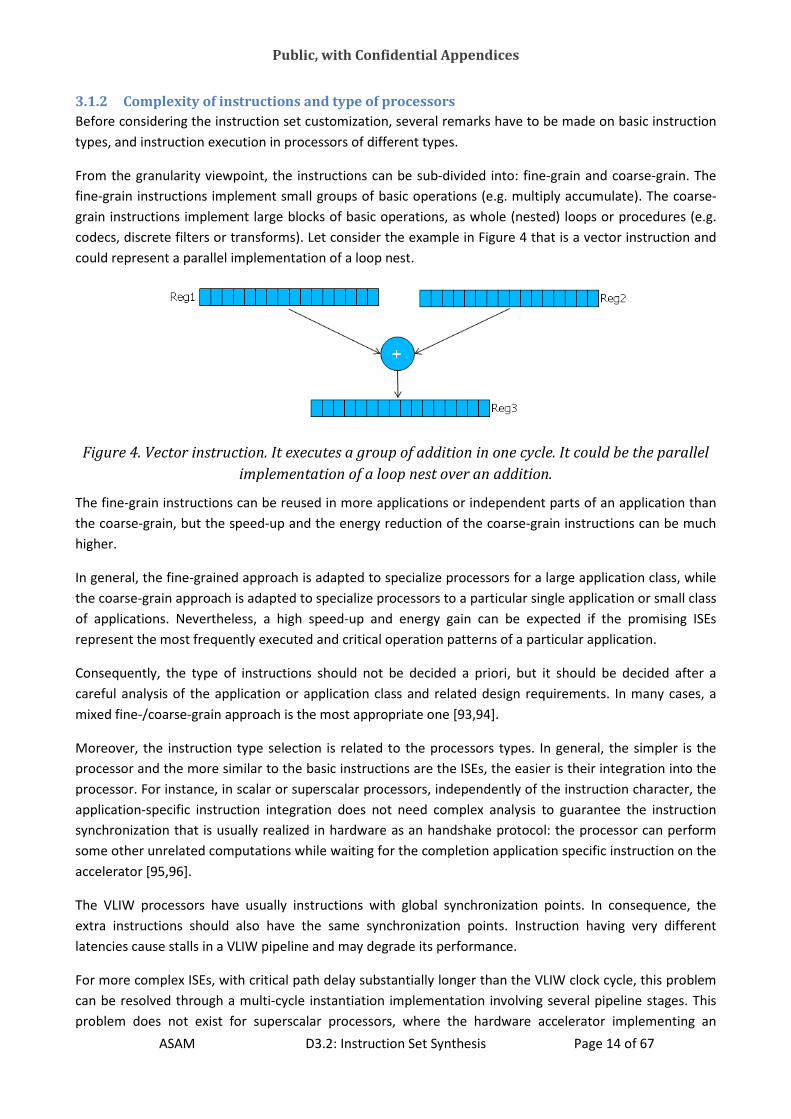
From the granularity viewpoint, the instructions can be sub
fine-grain instructions implement small groups of basic operat
grain instructions implement large blocks of basic opera
codecs, discrete filters or transforms).
could represent a parallel implementation of a loop nest
Figure 4. Vector instruction. It executes a group of addition in one cycle. It could be the parallel
implementation of a loop nest over an addition.
The fine-grain instructions can be reused in more applications
the coarse-grain, but the speed-up and
higher.
In general, the fine-grained approach is
the coarse-grain approach is adapted to specialize processors
of applications. Nevertheless, a high speed
represent the most frequently executed
Consequently, the type of instructions should
careful analysis of the application or application class and related design requ
mixed fine-/coarse-grain approach is
Moreover, the instruction type selection is related to
processor and the more similar to the basic instructions
processor. For instance, in scalar or superscalar
application-specific instruction integration
synchronization that is usually realized in hardware as an handshake protocol
some other unrelated computations while waiting for the
accelerator [95,96].
The VLIW processors have usually instructions with global synchronization points
extra instructions should also have the same
latencies cause stalls in a VLIW pipelin
For more complex ISEs, with critical path delay substantially longer than the VLIW clock cycle, this problem
can be resolved through a multi-cycle instantiation implementation involving several pipeline stages.
problem does not exist for superscalar processors, where the hardware accelerator implementing an
Public, with Confidential Appendices
D3.2: Instruction Set Synthesis
Complexity of instructions and type of processors
Before considering the instruction set customization, several remarks have to be made on basic instruction
types, and instruction execution in processors of different types.
viewpoint, the instructions can be sub-divided into: fine-grain and coarse
grain instructions implement small groups of basic operations (e.g. multiply accumulate).
nt large blocks of basic operations, as whole (nested) loops or procedures (e.g.
filters or transforms). Let consider the example in Figure 4 that is a vector instruction and
could represent a parallel implementation of a loop nest.
. Vector instruction. It executes a group of addition in one cycle. It could be the parallel
implementation of a loop nest over an addition.
grain instructions can be reused in more applications or independent part
up and the energy reduction of the coarse-grain instructions
grained approach is adapted to specialize processors for a large application
adapted to specialize processors to a particular single application or small class
high speed-up and energy gain can be expected if the promising ISE
executed and critical operation patterns of a particular
Consequently, the type of instructions should not be decided a priori, but it should
careful analysis of the application or application class and related design requirements. In many cases, a
grain approach is the most appropriate one [93,94].
Moreover, the instruction type selection is related to the processors types. In general, the simpler is
the basic instructions are the ISEs, the easier is the
r superscalar processors, independently of the instruction character, the
specific instruction integration does not need complex analysis to guarantee
synchronization that is usually realized in hardware as an handshake protocol: the processor can
some other unrelated computations while waiting for the completion application specific instruction
ave usually instructions with global synchronization points
extra instructions should also have the same synchronization points. Instruction
LIW pipeline and may degrade its performance.
For more complex ISEs, with critical path delay substantially longer than the VLIW clock cycle, this problem
cycle instantiation implementation involving several pipeline stages.
problem does not exist for superscalar processors, where the hardware accelerator implementing an
Page 14 of 67
Before considering the instruction set customization, several remarks have to be made on basic instruction
ain and coarse-grain. The
ions (e.g. multiply accumulate). The coarse-
tions, as whole (nested) loops or procedures (e.g.
that is a vector instruction and
. Vector instruction. It executes a group of addition in one cycle. It could be the parallel
or independent parts of an application than
grain instructions can be much
large application class, while
to a particular single application or small class
up and energy gain can be expected if the promising ISEs
and critical operation patterns of a particular application.
not be decided a priori, but it should be decided after a
irements. In many cases, a
processors types. In general, the simpler is the
the easier is their integration into the
of the instruction character, the
guarantee the instruction
he processor can perform
application specific instruction on the
ave usually instructions with global synchronization points. In consequence, the
nstruction having very different
For more complex ISEs, with critical path delay substantially longer than the VLIW clock cycle, this problem
cycle instantiation implementation involving several pipeline stages. This
problem does not exist for superscalar processors, where the hardware accelerator implementing an

Public, with Confidential Appendices
ASAM D3.2: Instruction Set Synthesis Page 15 of 67
application-specific instruction can be used the same way as a regular functional unit of the superscalar.
Unfortunately, super-scalar processors often use complex hardware to dynamically identify parallel
processing opportunities, and in consequence, are less suitable for embedded applications. In contrary,
VLIW processors exploit compilers for finding instructions for parallel execution, and consequently, have a
much simpler hardware.
3.1.3 Open issues in instruction set synthesis
The major challenge of the instruction set customization is the lack of adequate design automation tools
that enable an efficient automated application analysis and instruction set customization. In the current
engineering practice, application profiling and analysis are quite well supported by compilers and other
automatic tools, but instruction customization is often limited, and either performed manually or only
partly automated for some specific configurable ASIP architectures (see e.g. [9][21][13][14][19][97]).
In the next sections we discuss the main existing methods for ISE identification and selection and hardware
instruction generation.
3.2 Pattern Identification
Custom instruction identification consists of analysis of a graph-based application representation to find
some critical and repeating sub-graphs (operation patterns) that are good candidates to be converted into
single custom instructions.
The search for the candidate patterns (instructions) is an optimization problem. Thus the number of its
possible solutions is limited by exploration constraints and the search of the optimal solutions is guided by
quality metrics. The exploration method can be exhaustive or based on heuristics. In the following we give
brief information on the exploration constraints, quality metrics and exploration methods used in the
existing works on pattern identification.
3.2.1 Exploration constraints
The exploration constraints are summarized in Table 1 and are usually imposed by the type of architecture,
under the consideration of the targeted implementation technology or guarantees of a proper scheduling
(e.g. related to the number of inputs and outputs, patterns convexity, operation type, etc.). The aim of
these constraints is to facilitate the identification of the most promising candidate patterns in the
application graph and to support pruning of the set of possible patterns during the instruction
identification, if the solution space is too large.
Table 1. Usual constraints of the optimization problem of promising patterns identification
Architecture type Proper Scheduling
Extra instruction execution time in VLIW Nbr. of instruction I/O ports for data access
scheduling
Technology type Patterns convexity
nbr. of instruction I/O ports for realization on an
external FPGA
Instruction granularity
Extra instruction with Internal states

Public, with Confidential Appendices
ASAM D3.2: Instruction Set Synthesis Page 16 of 67
3.2.2 Quality metrics
The quality metrics express the effectiveness and efficiency of a pattern and are related to various
characteristics of the hardware implementing the individuated instructions, as the execution time,
power/energy consumption, used hardware resources, etc, but often describe the properties at a more
abstract level. Their aim is to compare the quality of the considered solutions to each other and provide
selection criteria for the most promising solutions. Table 2 summarizes some of the most commonly used
quality metrics.
The instruction identification methods proposed in [98-103] are aimed at maximizing the spatial reuse of
patterns and are mainly based on statistics of pattern occurrences in the application graph. This often
results in quite small and simple patterns that are often worthless to be realized onto external specific
hardware because they do not guarantee a sufficient execution speedup. Several works show that larger
and more complex patterns result in higher speedups (e.g. [104-106]) and different metrics have to be used
to achieve them as for example in [6]. For higher speedups, not the spatial reuse of patterns, but rather
their temporal reuse should be maximized.
Table 2. Quality metrics of the identification problem.
Objectives Methods Papers
Minimized the spatial re-use (of
small and simple patterns)
Statistics of pattern occurrence in
the CDFG
[98-103]
SpeedUp brought by the larger
and complex ISE (maximize the
temporal re-use)
[104-106] [6]
Reduce the avarage execution
time
Identify the most frequently
executed patters
[105,107]
Reduce the worst-case
execution time (for hard-real
time application)
Identify the time consuming
instructions on the critical path
[104,108]
Reduce the dynamic
reconfiguration time for
reconfigurable ASIP
[109-111]
Reduce the extra cycle needed
to share hardware between the
processor and the extension
[112]
To reduce the average execution time, the most frequently executed patterns should be identified, as e.g.
patterns on the most frequently executed paths [105,107]. To reduce the worst-case execution time and
satisfy hard real-time constraints, the patterns most frequently occur on the critical and near-critical paths
are extracted [104,108]. In [108] the worst-case execution time is used as a metrics to guarantee
satisfaction of the real-time constraints. In [109-111], the dynamic reconfiguration cost is accounted for,

Public, with Confidential Appendices
ASAM D3.2: Instruction Set Synthesis Page 17 of 67
and in [112] the extra clock cycles to move data between the register files and hardware units
implementing the new instructions, as well as hardware sharing among the hardware units.
3.2.3 Pattern Identification methods
Some simple methods for instruction pattern identification are listed in Table 2. In addition to these
methods, Table 3 gives summarizes some more complex ones, that are also the most frequently used in
the existing literature.
Some other approaches [99,100,103,107] use specific heuristics to identify some promising patterns while
discarding some less promising ones. The method proposed in [107] and several other methods find
possible custom instruction candidates, while pruning the search space based on the input or output
constraint violation by the candidate sub-graphs, operation type, convexity, etc.
Table 3. Most used methods for instruction pattern identification.
Methods Papers
Using heuristics (ex. Constraints violation or
dominated quality metrics) to discard less
promising patterns
[99,100,103,107]
Growing patterns around a seed node while
considering the quality metrics of the pattern.
[94] and [106]
Template matching and sub-graph isomorphism
(find the most occurrent sub-graphs that macth
pattern templates in an existing library of
possible ISEs)
[64,106]
[4,6,69,70,74,78,82,84,86,88,89,93,98,100,103,106,112-
122]
Template generation (ca be used as a front-end
to the template matching to form the template
library)
[4,29,70,86,88,90,93,99,101,103,121,123]
Exhaustive exploration [102] [124,125][107][6]
The methods proposed in [94] and [106] incrementally grow patterns when observing performance gains
and penalties related to the input or output constraint violation. A commonly used concept in the custom
instruction identification is this of a template. Template is an operation pattern known or assumed to be a
promising candidate for a custom instruction. Custom instruction identification can be performed as
template matching or template generation. Template matching assumes the existence of a template library
and consists of finding the number of occurrences in the application graph or the number of repetitive
executions of particular existing templates from the template library (e.g. [64,106]). The most frequent
templates are then implemented as custom instructions. This problem is similar to the sub-graph
isomorphism problem [4, 6, 69, 70, 74, 78, 82, 84, 86, 88, 89, 93, 98, 100, 103, 106, 112-122], and it is
known that the directed sub-graph isomorphism problem is NP-complete [126].

Public, with Confidential Appendices
ASAM D3.2: Instruction Set Synthesis Page 18 of 67
Template generation consists of creating new templates (e.g. [4, 29, 70, 86, 88, 90, 93, 99, 101, 103, 121,
124]). Usually it starts with selection of a particular node or a larger pattern to be a seed, and gradually
grows the seed through absorbing some neighboring nodes, when observing the influence of the pattern
growth on its parameters included in the constraints and objectives of the pattern quality metrics that
guide the search. The pattern optimizing the quality metrics is accepted as a new template. After
constructing one or more new templates, the number of template occurrences in the application graph or
the number of their repetitive executions is checked to prune the less frequent templates or to accept the
most frequent once. Some approaches that combine the template matching with generation have also
been proposed (e.g. [93,102]). In [127] it has been demonstrated that the number of different prevalent
data-flow patterns in popular multimedia benchmarks is very limited (approximately 10 patterns). In
[128,129] this has been experimentally proven for the second time. It has been demonstrated that a
relatively small number of predefined templates, called morphable structures, is needed for a near-optimal
instruction set customization for the relatively narrow multimedia application class, and a rapid custom
instruction generation method is presented based on this fact. The same is proven for the third time in
[130]. A similar idea of the custom instruction generation speedup through only considering the major
blocks of CDFG is presented in [131].
In general, the problem of custom instruction identification is of exponential complexity, because the set of
possible new custom instructions grows exponentially with the number of the application graph nodes. In
the past, exhaustive enumeration, several dynamic programming-based algorithms (e.g. [102]) and Integer
Linear Programming algorithms (e.g. [124,125] ) have been proposed to solve the problem, but these
approaches are not efficient for larger general problem instances [107]. Consequently, to efficiently solve
this problem for large instances, only some easier to process specific application graphs and/or sub-graphs
should be considered, or adequate heuristic algorithms have to be used. [6] proposes an exhaustive
method (in the sense that the whole solution space is explored) that includes pruning techniques that
largely reduce the exploration time and cost with the consequence that the optimal solutions are found in a
reasonable time.
3.2.4 The most often used simplifications for the identification problem
Table 4. Used simplification in pattern identification problem.
Simplifications Papers
Acyclic graph All read papers
Connected graph [102,106,108,132][133]
The non-overlapping templates [107,133]
Number of I/O output (MAXMISO, valid sub-
graphs)
[107,134][135][134,136][137].
The solution difficulty of the instruction identification problem depends on the kind of application graphs
and sub-graphs (templates, operation patterns, instructions) considered. For this reason simplifications,
such as summarized in Table 4, are used to handle the IS synthesis problem. In particular, since cyclic
graphs cannot be easily sorted, acyclic graphs are considered in most cases. Although a cyclic graph can be

Public, with Confidential Appendices
ASAM D3.2: Instruction Set Synthesis Page 19 of 67
transformed into an acyclic one (e.g. through unrolling the cycles), this significantly increases the graph
complexity.
Also, only connected graphs are considered in most cases (e.g. [102,106,108,132][133] [109]), and
disconnected graphs are processed in parts through processing their connected components, despite the
fact that the direct consideration of the disconnected graphs makes possible a more effective parallelism
exploitation (e.g. [70,104,106,133]).
Moreover consideration of multi-output templates and overlapping templates during the custom
instruction generation and selection is difficult [107,133]. During instruction generation the disjoint
templates are usually considered, and the nodes absorbed into a template are immediately removed from
the application graph. Although the overlapping templates consideration can potentially produce better
results, their consideration drastically increases the problem difficulty, and additionally, the costs related to
replication of the common nodes of the overlapping templates may sometimes exceed the performance
gains due the overlapping template consideration.
Regarding the number of outputs of a sub-graph (template, operation pattern, instruction) the following
two types of sub-graphs can be distinguished: multiple inputs single output (MISO) and multiple inputs
multiple outputs (MIMO). MISO sub-graphs of maximal size are called MAXMISO.
The type of patterns or instructions considered directly relates to the instruction identification problem
complexity. The exhaustive enumeration of MISO patterns is exponential, as it is strictly related to the sub-
graph enumeration problem which is known to be exponential [107,134]. However, the exhaustive
enumeration of MAXMISO patterns is linear in the number of nodes [135], because the intersection of
MAXMISO patterns is empty.
Since the identification of MIMO instructions may result in more significant performance gains, some
algorithms combine MAXMISO instructions per levels in order to obtain MIMO instructions, i.e. several
MAXMISO instructions of the same level of a reduced graph are combined into one convex MIMO
instruction. Works based on this idea are presented in [134,136] and a frame work for the automatic
generation and selection of convex MIMO instructions in [137].
In [70] the identification of convex MIMO instructions is presented through clustering of MAXMISO
instructions to maximally exploit the MAXMISO-level parallelism. In this algorithm, the convexity is
guaranteed by construction. Through extension of this algorithm, a heuristic linear complexity algorithm
has been constructed for identification of convex MIMO instructions [134].
Some other papers present sub-graph enumeration algorithms limited to only the so-called legal patterns
which are the convex sub-graphs that satisfy some architectural constraints, as number of I/O operands,
pipeline depth, and other constraints [109] [67,99,100,105]. While the number of all sub-graphs is
exponential, the number of legal sub-graphs is polynomial [138].
3.2.5 Detailed examples of pattern identification methods
In this section we give some detailed examples of existing methods for instruction pattern identification.
The idea is to give a more insight into the problem and its existing solutions. Most of the presented pattern
identification methods are included in some longer frameworks for ASIP customization. We also briefly
present the corresponding frameworks.

Public, with Confidential Appendices
ASAM D3.2: Instruction Set Synthesis Page 20 of 67
The DURASE system and its pattern identification
The DURASE system is a framework to generate instruction extensions for application-specific
reconfigurable processors. Its input consists of a C-written application description, a model of the target
architecture and the basic instruction set to be extended. Its output consists of an FPGA-implemented
processor extension and the instructions to access this extension. The analysis part involves a code
optimization front-end based on the GECOS compiler and including polyhedral transformations for data
parallelism [26].
Figure 5.The DURASE system.
In this section, we discuss identification of computational patterns from [82], but the DURASE design
process also involves selection of specific patterns that speed up application and will be presented in section 3.3.3.
In the DURASE pattern identification the two following methods are used: a graph covering method using
constraints programming (CP), to find some promising covers of the application graph with the identified
patterns and to ensure the validity of identified patterns with respect to the architectural and technological
constraints, and the graph matching, to identify patterns with the highest occurrence. The entry point is an
acyclic graph that can be inferred by unrolling a cyclic graph.
The pattern identification has three steps:
1) During the first step, a CP-based covering of the initial graph identifies all possible computational
patterns that respect three kinds of constraints: the convexity of the pattern, the number of I/Os of

Public, with Confidential Appendices
ASAM D3.2: Instruction Set Synthesis Page 21 of 67
the individuated sub-graph (i.e. the number of incident or exiting edges of the sub-graph) and a
coarse estimation of the implemented ISE delay.
2) The second step of the identification, prunes the space of the identified patterns by considering
only the non-isomorphic ones.
3) The third step further prunes the space of identified patterns by preserving only the patterns that
have a number of occurrences in the original application graph that is comparable to those of their
single nodes.
This algorithm identifies small and recurrent patterns that improve the pattern re-use but does not ensure
finding the higher efficiency larger application-specific patterns. Its strength is in the formal definition and
usage of architectural and technological constraints that help finding a number and kind of patterns
ensuring a high coverage of the initial graph.
Such an approach can be re-used in a full IS customization to determine an initial basic IS already tuned to
the application. In this case, the pattern generation should also include a constraint on the availability of
the individuated sub-graphs in a pre-existing technology-related library.
ISA Customization based on LANCE-compiler and generating LISA-based ASIP
descriptions
The method [73] proposes a generic adaptable flow to design Application specific ISE either for full custom
ISEs or for ISA adaptation.
The ASIPs are usually composed of a base processor and several ISEs, that can be implemented as custom
functional units on co-processors tightly coupled with the base-processor core. They consider an ASIP
design flows based on reconfigurable/configurable processors that are extendable.
They distinguish three phases in an ASIP design:
1) The application profiling, that finds the bottlenecks and other hotspots of an application
2) ISE identification that analyzes the DFG of the hotspots and combines together some arithmetic,
logic and data-transfer operations into a single specific instruction.
3) Verification and integration of ISEs into ASIP. This step consists in:
a. Conversion of the DAG in a data-path
b. Re-targeting ASIP compiler
c. IS simulation & verification
This method is intended to find larger, not-reusable, but optimized instruction set extensions to be
implemented on an external co-processor.
Figure 6 presents the proposed ISA customization flow. The input is a C-code that is transformed in an
intermediate representation (three-address code IR). Then the ISE identification transforms this IR in a
CDFG by using information from the micro-profiler and architectural constraints. Here there is the first loop
of optimization. Finally the back-end takes the annotated/optimized CDFG and produces either partial
extension for a configurable processor or a whole ADL design of an ASIP. In the back-end there is another
optimization loop (DSE) to infer the ADL design.
They have two methods for ISE identification. The first method is based on ILP; it iteratively adds new
nodes (instructions) to an ISE and maximizes an objective function while respecting architectural

Public, with Confidential Appendices
ASAM D3.2: Instruction Set Synthesis Page 22 of 67
constraints. The second method uses HLS technique to pipeline the instructions of the hotspots on several
ISEs and then it generates ADL through LISAtek. This method establishes a set of forbidden instructions,
such as “processor state update”, “load”, “store”, etc., that can only run on the base-processor. In these
two methods, it is possible to have architectural constraint, such as the number of I/O ports of the ISE (i.e.
on the number of general purpose registers used for the communication between the basic processor and
the ISEs) and the number of used HW resources and scratch-pad memories.
The back-end of the ISA customization produces a transformed C and RTL (Verilog). The C can be integrated
in Coware corXpert for ESL system-IP generation or in LISATek for ASIP design and ADL generation.
In [76] another pattern identification method for custom instructions is presented. The main contribution
of this work is twofold: it takes into account the bandwidth limitation, due to the limited number of the
General Purpose Registers (GPRs) used in the communication between the core processor and the external
custom ISE, and it considers the possibility to overcome this limitation by using Internal Registers (IRs).
The proposed pattern identification method is exemplified in Figure 7. It accounts for three types of
constraints and is executed in two steps. The used constraints are: data-flow related, i.e. the convexity and
schedulability of the individuated pattern; constraints on area and latency of the possible custom
instructions and the architectural constraints on the number of available GPRs.
The two steps of the custom pattern identification use Integer Linear Programming (ILP) to locally optimize
the two problems of first iteratively finding an optimal partitioning of the initial DFG representing the
application hotspot to be speeded-up, and then maximize the number of communications using GRP; while
still allowing for communications between the core processor and the extension based on IRs.
Figure 6. ISA customization flow.
The main concern (and architectural constraint) of this method is the limitation on the number of GPR for
the communication between the basic processor and the ISEs. In the case when custom instructions do not
need to be realized on external hardware support but can be realized as internal instructions (HIVElogic)
this limitation is less important, because the communication can always happens through IRs. This method
does not have an explicit phase of selection because the number of identified IS extensions is limited by
construction in the searching algorithm.

Public, with Confidential Appendices
ASAM D3.2: Instruction Set Synthesis Page 23 of 67
Figure 7. Custom Instruction identification for ISA customization in LANCE/LISA-based
methodology.
After the identification, the found partitioning goes through a phase of scheduling and register allocation
before the actual hardware implementation.
Enumer07 and newenumer and maximal valid sub-graph methodologies
In [67,85], the authors propose an improvement for the existing methods to extract ISEs by adding new
pruning criteria. They classify the existing methods with respect to the method used to solve the
identification problem: reducing the exploration space, heuristics or genetic, exhaustive branch-and-bound,
single-output small blocks, clusterizing and connected graph. They improve the Enumer07 that is a pattern
identification method that handles disconnected multi-output graphs. The problem statement is the
following: find valid patterns in an input DFG so that: patterns are convex, they have a limited number of
I/O and do not contain invalid operations. As the original one, the improved enumer07 has 3 steps:
node_select, unite and split. In the improved enumer07 the used optimization criteria are improved and the
identification is more efficient. Node_select starts from an empty pattern and iteratively selects a valid new
node from the input DFG. Unite treats node that can be added to the constructed pattern and split treats
node that cannot be added by splitting the input DFG in disconnected graphs. In this paper they propose
new criteria to pruning the exploration space in select and unite. The first criterion is the violation of I/O
constraints (if this violation cannot be solved by expanding the node) the corresponding branch of the
graph is pruned. The second criterion is the single-output constraint to decide if a node is connected to the
constructed pattern or not.
Maximal valid sub-graph method
The maximal valid sub-graph is a convex sub-graph that does not contain invalid nodes. A sub-graph is said
to be convex, if all the paths connecting its nodes are contained in the sub-graph itself and the forbidden
instructions are user-defined and usually include load, store, branch, jump, etc. Based on the definition of
Maximal Valid Sub-graph (MVS), a fast method to enumerate (or identify) promising patterns is presented
in [79].

Public, with Confidential Appendices
ASAM D3.2: Instruction Set Synthesis Page 24 of 67
Figure 8. The Maximal Valid Sub-graph method.
On the contrary of other methods generating patterns by merging neighbor nodes, this method solves the
problem in a top-down manner. They propose a formally defined and correct by construction method. The
method iteratively considers and eliminates from the graph the invalid nodes. During a given iteration of
the successive eliminations, it enumerates all the possible maximal convex patterns. If these patterns do
not contain invalid instructions, they are marked as identified instruction patterns. On the base of this
definition, we exemplify the method with respect to Figure 8. The graph G in the figure has three invalid
nodes (1, 4 and 8). At the first iteration, node 4 is eliminated and a single convex sub-graph G1 still
containing invalid instruction is created. From G1 and by eliminating node 8, two possible sub-graphs G21
and G22 are inferred. Note that G21 is not connected but convex and does not contain invalid instruction,
thus it is selected as promising instruction pattern. This method selects large patter and is appropriated for
ISE on dedicated external hardware.
Upak system
In [88,89], the authors present a method to automatically generate an application specific reconfigurable
HW accelerator.
The ASIP design includes: the identification of frequent computational patterns, the selection of a sub-set
of these patterns for which the mapping and scheduling reach the maximal coverage of the application
graph. The flow is composed of three steps and is presented in Figure 9.
During the first step, some promising computational patterns are identified form a hierarchical input
application graph. This step is described later in this section. During the second step, the identified patterns
are used to explore which patterns will be used in a particular scenario for application execution. This is
done during the scheduling and pattern selection phase using specific methods built on the top of the
constraint programming solver JaCoP. The input to this phase contains the identified patterns, the ASIP
architecture model and the specific scheduling constraints (e.g., execution time limit or resource
constraints). This is described in section 3.3.3. The output of the system is a set of the selected patterns and

Public, with Confidential Appendices
ASAM D3.2: Instruction Set Synthesis Page 25 of 67
a corresponding schedule for execution of the application using the selected patterns and processor
instructions.
Figure 9. Upak flow.
The first step of the method generates a set of promising instruction patterns, by having all the nodes of
the application graph as seeds. Subsequently, it is checked if the generated patterns are isomorphic to each
other and then the patterns having a maximal coverage are selected (i.e. the patterns having the highest
number of matches within the application graph are selected). Thus, for each generated pattern a graph
matching algorithm is used. It checks if the type, the I/O structure and the neighborhood structure of two
graphs match with each other. At the end of this iterative process, a Definitively Identified Pattern Set is
selected.
All the patterns in the DIPS are merged to form a unique HW cell. To merge the patterns, they first
construct a compatibility graph, where the compatible operations (i.e. operations having the same type and
structure) are mapped to the same node or edge. Then, they find the maximum weighted clique to realize
the merged patterns. This clique is then scheduled with time or resources constraints, by using 2D
rectangles that represent the time during which each node (instruction) is alive.

Public, with Confidential Appendices
ASAM D3.2: Instruction Set Synthesis Page 26 of 67
Figure 10. Two iterations of the pattern identification method in Upak.
Maximal-clique-based methodology
The paper [87] proposes a method to identify ISE by solving maximal clique problem and by serializing I/O
of the custom functional unit. The proposed method clusterizes the nodes of the input CDFG in equivalence
class. Then, it constructs a Cluster Graph and finds the maximal cliques (connected graphs) that are
potential optimal ISEs. Finally it serializes I/O on the found ISEs and selects the ones having the maximal
speed-up and smallest area. To limit the number of considered ISE, they define a set of forbidden
instructions (load, store and jump) that cannot be executed on the extension.

Public, with Confidential Appendices
ASAM D3.2: Instruction Set Synthesis Page 27 of 67
Figure 11. The maximal clique method.
They use a time model to define an objective function of the ISE identification. In fact, they characterize
each node with two metrics (SW and HW) giving the number of cycles needed to execute the node in
software or in hardware. The objective function to be optimized is the overall sum of cycles needed to
execute software instructions minus the overall sum to execute hardware instructions.
3.3 Instruction Set Selection
Custom instruction selection consists in selecting the most promising sub-set of custom instructions from
the set of custom instructions constructed in the process of custom instruction identification or already
existing in a given library. As the identification problem the selection is an optimizing process based on
quality metrics and using some exploration methods. Next sub-sections describe the metrics and methods
most frequently used in published research.
3.3.1 Quality metrics
The selection is realized using some quality metrics involving evaluation of an instruction sub-set in terms
of performance, area, power consumption, etc. after its realization in hardware. These quality metrics are
similar to those used for the instruction identification, but at this time the metrics should express the
effectiveness and efficiency of an instruction set and not the quality of particular instructions. Table 5
summarizes the most frequently used quality metrics.
[139] presents an algorithm that aims at selection of a minimal set of instructions that maximizes the
number of covered nodes in the application graph. An interesting observation of the experimental research
of this work is that increasing the number of different instructions (patterns) used to solve the coverage
problem, results in a significant increase of the number of nodes covered only up to a certain level, above
which, usage of more templates does not substantially influence the number of nodes covered.
Consequently, a reasonably small number of well-designed and adequately selected custom instructions
can result in a significant performance gain.

Public, with Confidential Appendices
ASAM D3.2: Instruction Set Synthesis Page 28 of 67
Table 5. Most used quality metrics to solve the selection problem
Quality metrics for the selection problem
Metric Paper
maximizes the number of covered nodes [139]
minimizing the number of distinct instructions used [140]
maximizing the number of pattern occurrences [91,141]
maximizing the execution frequency [101,105,108][104]
Accounting for the occurrence of specific nodes [93]
Optimizing resource sharing [143,144]
Other methods aim at minimizing the number of distinct used instructions [140], maximizing the number of
pattern occurrences [91,141], the execution frequencies [101,105,108][104], the occurrence of specific
nodes [93] or the resource sharing [143,144].
3.3.2 Exploration methods
The instruction selection problem is a specific graph coverage problem that is known to be NP-hard [145].
Consequently, to solve this problem for large and complicated instances, some heuristic algorithms have to
be used.
Table 6. Most used methods for the exploration of the optimal Instruction Set selection.
Methods of the selection problem
Method Paper
Linear programming [125,134,146]
Branch-and-bound [112][147,148]
Heuristics [149][99,119,132]
Constraint programming [26,69,82]
In the past, several exact LP-based algorithms have been proposed [125,134,146] for instruction selection
and some branch-and-bound-based algorithms [112], as well as, some branch-and-bound-based algorithms
for general covering problems [147,148] and some effective and efficient heuristic algorithms for similar
coverage problems [149].
Also, some other heuristic methods have been proposed for instruction selection (e.g. [99,119,132]).
Especially the method discussed in [119], which is based on constraint programming and performing the
final instruction selection during scheduling and mapping seems to be very promising.

Public, with Confidential Appendices
ASAM D3.2: Instruction Set Synthesis Page 29 of 67
Recently, new instruction set customization method, based on constraint programming and including an
automatic tool-chain, was presented in [26,69,82]. This method is adapted to heterogeneous embedded
multi-processor systems involving (re-)configurable embedded processors and reconfigurable hardware
accelerators.
3.3.3 Detailed examples of instruction set selection methods
In this section we give some detailed example of existing methods for instruction set selection.
The DURASE system and its selection method
This sub-section gives information about the selection in the DURASE system previously presented in 3.2.5.
This selection method presented in [69] uses constraint programming to model and solve instruction
selection for processors that can be extended with a functionality mapped on reconfigurable cell fabric
(FPGA). Starting from a hierarchical graph of the application, that captures data and control dependences,
The DURASE system first performs a patterns identification phase, then it performs the patterns selection
and instructions scheduling and mapping. As described in 3.2.5, the pattern identification is based on
constraints programming: the search targets patterns that are not isomorphic and satisfy some
architectural and technical constraints. The identified patterns are promising candidates for hardware
realization. From the set of these patterns, the DURASE system selects those resulting on the best
hardware performances when used in a unique application specific instruction set. To achieve this aim, the
DURASE system solves concurrently the scheduling and the matching of the application graph onto a set of
possible patterns candidates (also called matches) found during pattern identification. The method first
constructs a matching (coverage) matrix between application nodes and matches. Then it solves a graph
matching problem with resources and time constraints.
Figure 12. Example of a nodes and identified patterns matching.
Figure 12 gives an example of matching matrix between nodes and identified promising patterns. A point in
the matrix indicates a possible matching between a promising patterns mi and a node nj. A black point
indicates a selected specific matching.
To select the specific matches, the method uses an abstract model for scheduling and mapping as shown in
Figure 13. The promising patterns mi are represented as 2 dimensional rectangles whose height represents
the number of used resources and whose width represents the time latency. The aim is to minimize the
scheduling length under resource constraints. The rectangle heights and widths are the variables of a
constraint programming problem defined over a finite domain.

Public, with Confidential Appendices
ASAM D3.2: Instruction Set Synthesis Page 30 of 67
Figure 13. Temporal and resource constraints model to select promising ISE.
Some other details are added to enrich the scheduling and mapping model. These details are:
1) The usage of both a single and multiple nodes matching model, the first one represents the
mapping of tasks on the basic processor and the second one represents the mapping of tasks onto
the parallel ISEs.
2) The categorization of the rectangles according to the kind of task that they represent, e.g. a task on
an extension has to take into account the time to transfer data in input and in output, these tasks
are classified in category C. Category A of tasks includes the launching of tasks on ISEs and the
control on the status of the processor. Category B indicates the launching, data transfer and
computation execution on ISEs.
Optimal sub-graph covering for VLIW processors
In [72], the authors propose a method to optimize the IS selection in the case of VLIW processors.
The instruction set selection is solved as a sub-graph covering problem minimizing the execution time of
the realized task. Instead of solving the problem of minimizing the number of independent operators
covering the operations in the DFG of the application (i.e. Minimum Number covering (MNC) problem), the
authors solve the minimum length covering (MLC) problem, i.e. they minimize the length of critical path of
the ISE. The idea is that the MLC problem better targeted to multi-issue/VLIW processors.
They solve the problem with an exact method using dynamic (recurrent) programming and prune the
search space by applying several simplifications, such as:
1) Divide and conquer (only consider Single Input Single Output sub-graph to be explored with
dynamic programming, for the MIMO they enumerate all possible covering sub-graphs).
2) Sorting and pruning, sub graphs covering more nodes of the critical path have a priority of
selection and sub-graphs included in other (as fast) sub-graphs are pruned.
3) They use lower bound for critical path (branch and bound) and they prune non-convex solutions.

Public, with Confidential Appendices
ASAM D3.2: Instruction Set Synthesis Page 31 of 67
Figure 14. Boolean matrix between nodes
(1...16) and identified sub-graphs (a...g).
Figure 15. The dynamic programming
formulation.
The analysis starts with a Boolean mapping matrix (Figure 14) and solves the coverage problem with the
dynamic formulation given in Figure 15, which is equivalent to the Bellman-Ford algorithm that finds the
length path “i->j” by recursively considering the length of the sub-paths “i->k” and “k->j”. The considered
sub-paths are those identified by the Boolean matrix and the path length is replaced by the path delay
D[i,j].
For the CFU generation, the method produces a set of parameters to configure CFU template.
Rapid design of area-efficient custom instructions for reconfigurable embedded
processing
The following is an example of a comprehensive method including pattern identification (generation) and
selection.
In [74], the authors propose a rapid design space exploration framework for a first identification of a
reduced set of profitable application specific instructions for a VLIW architecture that can be extended with
an FPGA-based reconfigurable functional unit.
The proposed method involves the following three steps:
1) A phase of a pattern library construction Figure 16. This phase is a one-time effort aimed to
provide a library of patterns that are frequent for a given application or application domain. It
includes:
a. A pattern enumeration step that is based on the application profiling and enumerates the
most frequent patterns in the CDFG or a specific application of a group of GDFGs of
applications in the same domain (Figure 16.a).
b. A pattern grouping step that is based on the graph isomorphism: isomorphic sub-graphs
are grouped together and they are classified according to their number of occurrences
(frequency) in a pattern library (Figure 16.b).
After the phase 1) of pattern library construction has been executed once, the phases 2) and 3) are

Public, with Confidential Appendices
ASAM D3.2: Instruction Set Synthesis Page 32 of 67
iteratively repeated for each specific application.
Figure 16. Pattern library generation.
2) The template Library selection phase (Figure 17) is aimed to select some of the patterns from the
library constructed in phase 1) in order to have an optimal coverage of the application graph. This
second phase includes:
a. A template selection step (Figure 17.c) that takes as input the templates corresponding to
the patterns in the library of phase 1). This step assigns a gain to each pattern. The gain
considers only the speed-up that the assigned pattern brings to the execution time. Finally
this step selects the templates with the highest gains and forms a library of templates.
b. The selected library of templates is used by the next step: the pattern matching (Figure
17.d). This step computes the matching between the templates selected in phase 2).a and
some sub-graphs of the specific application. The matching is computed through a conflict
graph in which the nodes represent the matches between sub-graphs and templates, and
the edges represent a possible conflict between matches, i.e. two matches linked by an
edge realize common instructions. The optimal matching (Figure 17.e) is that having the
maximum number of independent matches (i.e. the largest sub-set of non-adjacent
vertices).
3) After finding the optimal matching, the method passes through a phase of hardware generation
(Figure 17.f and Figure 17.g). This is done by clusterizing the nodes of the output graph of the
matches selection into groups of instructions that can be realized on the same hardware resources.
The individuated clusters are realized on parallel ISEs. The optimization criterion of the cluster
generation and selection is the area occupancy of the selected clusters.

Public, with Confidential Appendices
ASAM
Figure 17
Selecting profitable custom instructions for reconfigurable processors
In [78], the authors propose a method to select candidates for custom
application as a graph of instructions and they find valid sub
constraints. They group the sub-graphs into “instances” of isomo
knapsack problem (chose the most useful things to bring in a limited
promising sub-graphs to be realized as custom instructions.
They use two criteria: a ratio gain to area and a ratio gai
algorithm, with a taboo search and a branch and bound.
A problem is that the chosen criteria
criteria, also if it can be used to express a
property of the device and gives less efficient results than a multi
Methodology to derive context adaptable architectures for FPGAs
In [86], the authors propose a method to design context adaptable architectures on partial and dynamically
reconfigurable FPGAs. The target applications are Data
as input different candidates DFGs. They found common sub
sub-graphs inside the initial DFG of the application
direct schedule (FDS) for the found
into the initial DFG, which now contains both CSGs (as custom instructions) and non
Finally the method iteratively select
FDS for these non-common sub-graphs
resources constraints on the CSG realization
Non-Common Sub-Graphs realization
Public, with Confidential Appendices
D3.2: Instruction Set Synthesis
17. Template, pattern and cluster selection.
Selecting profitable custom instructions for reconfigurable processors
propose a method to select candidates for custom-instruction sets. They model the
application as a graph of instructions and they find valid sub-set of instructions that
graphs into “instances” of isomorphic sub-graphs. Then they solve the
knapsack problem (chose the most useful things to bring in a limited-spaced sack) to find the most
graphs to be realized as custom instructions.
They use two criteria: a ratio gain to area and a ratio gain to re-use. They solved the problem with a greedy
search and a branch and bound.
criteria only account for re-use. Furthermore, the composition of weighted
criteria, also if it can be used to express a trade-off between criteria, does not represent a
and gives less efficient results than a multi-objective exploration
Methodology to derive context adaptable architectures for FPGAs
he authors propose a method to design context adaptable architectures on partial and dynamically
reconfigurable FPGAs. The target applications are Data-flow graphs embedded in control graph
as input different candidates DFGs. They found common sub-graphs (CSGs), which are frequently repeated
graphs inside the initial DFG of the application. For a given set of resources, they compute the force
nd CSGs. Then they substitute these CSG with a custom single instruction
into the initial DFG, which now contains both CSGs (as custom instructions) and non
iteratively selects the non-repeated sub-graphs of the initial DFGs
graphs and consequently up-date the resource set if needed. The time
realization also constrains the scheduling (and resource utilization) of the
s realization.
Page 33 of 67
instruction sets. They model the
set of instructions that satisfy the hardware
graphs. Then they solve the
spaced sack) to find the most
use. They solved the problem with a greedy
omposition of weighted
off between criteria, does not represent any physical
objective exploration.
he authors propose a method to design context adaptable architectures on partial and dynamically
flow graphs embedded in control graphs. They take
s), which are frequently repeated
. For a given set of resources, they compute the force
substitute these CSG with a custom single instruction
into the initial DFG, which now contains both CSGs (as custom instructions) and non-repeated sub-graphs.
ial DFGs and computes the
date the resource set if needed. The time and
the scheduling (and resource utilization) of the

Public, with Confidential Appendices
ASAM D3.2: Instruction Set Synthesis Page 34 of 67
HMP-ASIPs: heterogeneous multi-pipeline application-specific instruction-set
processors
The authors of [71] distinguish two phases in ASIP design: IS design, and processor structure, RF,
communication design. ASIPs usually adopt VLIW architectures and thus their architecture can be
optimized at compilation time with an adequate exploration process. The authors use architectures with
several parallel pipelines to achieve high performance systems. They can customize the architecture with
respect to the number of pipelines, instructions realized by the pipes and the forwarding paths, i.e. direct
links that forward the results from the previous instruction to the instruction that is currently executed in
the EX stage of a pipeline, this reduces the data hazards. The authors are concerned with the improvement
of forwarding paths when having parallel pipelines.
The design starts from a c-code that is compiled on single-pipe architecture. Then a scheduling for a multi-
pipe architecture is computed by supposing that all the FW paths are possible, finally the FW path are
reduced on the bases of the existing data-path. It is possible to re-order the instructions in the same pipe or
among different pipes without changing the data dependencies.
3.4 Instruction hardware (FU) construction and evaluation
Although the recent Mimosys Clarity tool [150] automatically identifies hardware accelerators from C code
and automates the HDL generation and implementation of an application on the PowerPC and accelerators
in XILINX FPGAs, it only delivers a single set of accelerators and does not enable any broader design space
exploration for finding different sets of accelerators that could meet various constraints, optimize different
objectives and realize different tradeoffs among the objectives. It is just a step in a good direction. Another
related tool, Synfora’s PICO Express FPGA synthesizes (hierarchical) coarse-grain application-specific
accelerators (instructions) for implementation in Xilinx Virtex and Spartan FPGAs. It performs algorithmic
synthesis of C algorithms into their corresponding optimized RTL code that is further synthesized into the
actual FPGA hardware with the tools of Synplicity and Xilinx. It makes possible a specific design space
exploration, creation of multiple implementations characterized with area and performance estimates, and
trade-off analysis [151]. The recent development in the reconfigurable ASIP field, the integrated
development environment (IDE) of Stretch, partially automates the instruction set extension and
application mapping on the Stretch families of S5000 and S6000 processors based on Xtensa and having an
embedded reconfigurable instruction set extension fabric (ISEF) within the processor. The developers of
systems based on the Stretch processors profile their applications expressed in C/C++, using the Stretch
profiler, identify the parts of application code that have to be accelerated in ISEF, and appropriately
annotate the C/C++ application code. These parts are then implemented as new instructions that are
executed in a single cycle. From the annotated code, the Stretch compiler produces both the ISEF
configuration and optimized application code, and configures the ISEF automatically [138].
3.5 Conclusion on the existing methodology for instruction set synthesis
Despite all the previous effort, no acceptable solution exists to the problem of fully automatic application
analysis, (re)configurable ASIP instruction set customization, customized ASIP platform construction, and
mapping of applications on such a customized platform. Since this problem is of high scientific interest and
practical relevance, it represents a very hot research topic, and numerous research results related to this
topic have been published recently [1,9,10,21,23-27,91-94]. An adequate full automation of the above
processes is necessary due to many factors, including the growing complexity and requirements of
application, designer productivity gap and short time to market requirement, as well as NP-hard character

Public, with Confidential Appendices
ASAM D3.2: Instruction Set Synthesis Page 35 of 67
of the problems to be solved and complex tradeoffs to be resolved by the selection of an optimized custom
instruction set from a usually huge set of candidate instructions and by the application mapping. As already
mentioned, instruction set customization is usually performed when using a graph-based (e.g. DFG, CDFG,
HCDG) representation of the application. Before starting the actual instruction set customization, various
transformation and parallelization techniques are often applied to the graph-based application
representation (e.g. [34-44]). Instruction set customization is usually performed in two steps, namely:
custom instruction identification and custom instruction selection. In the literature related to (re-)
configurable processors, instruction set customization is usually limited to instruction set extension,
although in general, it should consider the elimination of less useful instructions and of a related hardware
as well, of course, if this is at all possible. Furthermore, in the literature the custom instruction extending
the initial instruction set are usually realized on external accelerators implemented on ASIC or FPGA. In
consequence, one of the main requirements of their design is to minimize the communication between the
basic processor and the accelerator, and particularly, the number of General Purpose Registers used for the
communication between the basic processor and the external accelerating extension. In the case of the
Silicon Hive VLIW ASIP technology used in the ASAM project, the custom instruction extensions are realized
as internal instructions of the ASIP data-path being on the same chip and in the same issue slot as the basic
instruction set. Even if the number of I/O of a custom instruction has to be taken into account, this
problem is much less constraining than for the ISE identification and selection problems in the methods
described in the literature. Moreover, it is not so much required, as in the case of external accelerators, to
cluster all the found instruction extensions in a single MIMO complex instruction in order to reduce the
number of external accelerators to be implemented. Indeed in Silicon Hive technology the instruction set
extensions are treated, realized and used exactly as all the other instructions. With respect to the processor
type, the ASAM project targets SIMD and MIMD VLIW ASIP processors, which often include vector
instructions. For this reason, both the whole ASIP design and specifically the IS synthesis represent a much
more complex task, and introduce new design challenges with respect to existing works that are mainly
based on RISC extensible processors and only sometimes include some SIMD extensions. Another
important challenge in the ASAM IS synthesis is the selection of the initial IS during which the exploration
has to account for re-use. A further application specific IS extension step can resolve the remaining
bottlenecks.

Public, with Confidential Appendices
ASAM D3.2: Instruction Set Synthesis Page 36 of 67
4 Instruction Set Synthesis for ASAM This chapter is presented in the confidential section entitled Appendix: Instruction Set Synthesis for ASAM
on page 55.

Public, with Confidential Appendices
ASAM D3.2: Instruction Set Synthesis Page 37 of 67

Public, with Confidential Appendices
ASAM D3.2: Instruction Set Synthesis Page 38 of 67
5 Conclusion This document presented a survey of some promising existing Instruction Set (IS) synthesis approaches and
defined an initial proposal of the ASAM IS synthesis method.
One of the aims of the ASAM project is to provide an automatic framework for the IS synthesis that is one
of the fundamental steps of an ASIP design-flow.
Despite a large number of existing works on the IS extension and several works on the complete IS
synthesis, no acceptable solution exists to the problem of automatic instruction set customization for
complex customizable ASIPs, as those provided by Silicon Hive ASIP technology.
Instruction set customization is usually performed in two steps, namely: custom instruction identification
and custom instruction selection. In the literature, the instruction set customization is usually limited to the
instruction set extension, although in general, it should consider the selection of an initial extensible IS and
elimination of less useful instructions. Moreover, in the existing published methods the ISEs are mostly
realized as external accelerators implemented on FPGA or ASICs. Consequently, one of the main
requirements of their design is to minimize the communication between the basic processor and the
external accelerating extension. Adequately accounting for the I/O constraints is here one of the major
problems. If more ISEs are found they are usually merged in a single complex ISE to be realized on a single
external accelerator. The considered processors are often simple RISCs extended with RISC-based ISEs or
(rarely) with SIMD accelerators.
In the case of the Silicon Hive VLIW ASIP technology used in the ASAM project, the custom instruction
extensions are realized and used as all the other processor instructions. In consequence, although the
constraints on the number of I/O of a custom instruction, as well as the number and kind of the selected
instruction extensions have to be taken into account, they are much less constraining than in the case of
the ISE identification and selection problems discussed in the literature. With respect to the processor type,
the ASAM project targets SIMD and MIMD VLIW processors, which often include vector instructions. For
this reason, both the whole ASIP design and, specifically, the IS synthesis represent a much more complex
problem and introduce new design challenges comparing to existing works that are mainly focused on RISC
extensible processors and only sometimes include SIMD extensions.
Another important difference comparing to the existing works is that the ASAM IS synthesis aims at
selecting also the initial extensible IS. Only if necessary, it extends this set with some additional instruction
extensions to resolve eventual bottlenecks. Thus two main fundamental problems are presented here: the
initial application-specific IS selection and the application-specific instruction pool extension.
During the initial IS synthesis rather small re-usable instructions from the IS pool are used. For the
instruction pool extension larger and more complex instructions are usually selected in order to increase
the performance and efficiency brought by a particular instruction extension. Despite the mentioned
substantial differences between the instruction set related methods presented in the literature and the
methods needed for the VLIW ASIPs targeted in the ASAM project, when developing our new instruction
set synthesis method for customizable VLIW ASIPs, we plan to re-use some parts of some existing efficient
IS synthesis methods presented in the literature and adapt them to the case of the Silicon Hive technology.

Public, with Confidential Appendices
ASAM D3.2: Instruction Set Synthesis Page 39 of 67

Public, with Confidential Appendices
ASAM D3.2: Instruction Set Synthesis Page 40 of 67
6 Acknowledgements The authors of this deliverable are indebted Silicon Hive B.V, and especially to their representatives in the
ASAM project, for their collaboration with us in relation to this deliverable, and specifically, for efficiently
supporting us to quickly get well acquainted with the Silicon Hive technologies and tools.

Public, with Confidential Appendices
ASAM D3.2: Instruction Set Synthesis Page 41 of 67
7 Bibliography
[1] L. Jóźwiak, “Life-Inspired Systems and Their Quality-Driven Design,” Architecture of Computing Systems-ARCS 2006, 2006, p. 1–16.
[2] L. Jozwiak, “Life-inspired systems,” Digital System Design, 2004. DSD 2004. Euromicro Symposium on, IEEE, 2004, p. 36–43.
[3] L. Jozwiak and S. Ong, “Quality-driven model-based architecture synthesis for real-time embedded SoCs,” Journal of Systems Architecture, vol. 54, Mar. 2008, pp. 349-368.
[4] L. Jóźwiak, N. Nedjah, and M. Figueroa, “Modern development methods and tools for embedded reconfigurable systems: A survey,” Integration, the VLSI Journal, vol. 43, Jan. 2010, pp. 1-33.
[5] N. Dutt, “Configurable processors for embedded computing,” Computer, vol. 36, Jan. 2003, pp. 120-123.
[6] I. Paolo and R. Leupers, In Praise of Customizable Embedded Processors: design technologies and applications, San Francisco, California: Morgan Kaufmann/Elsevier, 2007.
[7] J. Henkel and N.E.C. Laboratories, “Closing the SoC Design Gap,” Design, 2003, pp. 119-121.
[8] K. Keutzer, S. Malik, and a R. Newton, “From ASIC to ASIP: the next design discontinuity,” Proceedings. IEEE International Conference on Computer Design: VLSI in Computers and Processors, 2002, pp. 84-90.
[9] R.E. Gonzalez, “Xtensa: A configurable and extensible processor,” Micro, IEEE, vol. 20, 2000, p. 60–70.
[10] C. Liem, F. Breant, S. Jadhav, R. OʼFarrell, R. Ryan, and O. Levia, “Embedded tools for a configurable and customizable DSP architecture,” IEEE Design & Test of Computers, vol. 19, Nov. 2002, pp. 27-35.
[11] F. Brandner, “Automatic Tool Generation from Structural Processor Descriptions,” Statistics.
[12] J.O. Filho, S. Masekowsky, T. Schweizer, and W. Rosenstiel, “CGADL: An Architecture Description Language for Coarse-Grained Reconfigurable Arrays,” IEEE Transactions on Very Large Scale Integration (VLSI) Systems, vol. 17, Sep. 2009, pp. 1247-1259.
[13] G. Hadjiyiannis, S. Hanono, and S. Devadas, “ISDL: An instruction set description language for retargetability,” Proceedings of the 34th Design Automation Conference, 1997, pp. 299-302.
[14] a Halambi, P. Grun, V. Ganesh, A. Khare, N. Dutt, and A. Nicolau, “EXPRESSION: A language for architecture exploration through compiler/simulator retargetability,” date, Published by the IEEE Computer Society, 1999, p. 485.

Public, with Confidential Appendices
ASAM D3.2: Instruction Set Synthesis Page 42 of 67
[15] a Hoffmann, O. Schliebusch, a Nohl, G. Braun, O. Wahlen, and H. Meyr, “A methodology for the design of application specific instruction set processors (ASIP) using the machine description language LISA,” IEEE/ACM International Conference on Computer Aided Design. ICCAD 2001. IEEE/ACM Digest of Technical Papers (Cat. No.01CH37281), 2001, pp. 625-630.
[16] S.F. Nielsen, J. Sparso, and J. Madsen, “Behavioral Synthesis of Asynchronous Circuits Using Syntax Directed Translation as Backend,” IEEE Transactions on Very Large Scale Integration (VLSI) Systems, vol. 17, Feb. 2009, pp. 248-261.
[17] J.H. Yang, B.W. Kim, S.J. Nam, J.H. Cho, S.W. Seo, C.-ho Ryu, Y.S. Kwon, D.H. Lee, J.Y. Lee, and J.S. Kim, others, “Metacore: an application specific dsp development system,” Proceedings of the 35th annual Design Automation Conference, ACM, 1998, p. 800–803.
[18] Target, “Target,” http://www.retarget.com/asip-advantage.php.
[19] J. Van Praet, G. Goossens, D. Lanneer, and H. De Man, “Instruction set definition and instruction selection for ASIPs,” Proceedings of the 7th international symposium on High-level synthesis, IEEE Computer Society Press, 1994, p. 11–16.
[20] SilicinHive, “HiveLogic,” http://www.siliconhive.com/Flex/Site/Page.aspx?PageID=17604.
[21] Y. Kobayashi, S. Kobayashi, K. Okuda, and K. Sakanushi, Synthesizable HDL generation method for configurable VLIW processors, 2004.
[22] J. Castrillon, D. Zhang, and T. Kempf, “Task management in MPSoCs: an ASIP approach,” Proceedings of the, 2009, pp. 587-594.
[23] M. Hohenauer, F. Engel, R. Leupers, G. Ascheid, and H. Meyr, “A SIMD optimization framework for retargetable compilers,” ACM Transactions on Architecture and Code Optimization, vol. 6, Mar. 2009, pp. 1-27.
[24] M. Imai and Y. Takeuchi, “Advantage and Possibility of Application-domain Specific Instruction-set Processor ( ASIP ),” Methodology, vol. 3, 2010, pp. 161-178.
[25] L. Jozwiak, “Quality-driven design in the system-on-a-chip era: Why and how?,” Journal of Systems Architecture, vol. 47, Apr. 2001, pp. 201-224.
[26] K. Martin, C. Wolinski, A. Floch, and F. Charot, “DURASE : Generic Environment for Design and Utilization of Reconfigurable Application-Specific Processors Extensions.”
[27] N. Vassiliadis, G. Theodoridis, and S. Nikolaidis, “Processors With Arbitrary Hardware Accelerators,” Integration The Vlsi Journal, vol. 17, 2009, pp. 221-233.
[28] K. Zhao, J. Bian, S. Dong, Y. Song, and S. Goto, “Pipeline-Based Partition Exploration for Heterogeneous Multiprocessor Synthesis,” IEICE Transactions on Fundamentals of Electronics, Communications and Computer Sciences, vol. E92-A, 2009, pp. 2283-2294.
[29] D. Liu, Embedded DSP Processor Design: Application Specific Instruction Set Processors, Morgan Kaufmann/Elsevier, 2008.
Public, with Confidential Appendices
ASAM D3.2: Instruction Set Synthesis Page 43 of 67
[30] F. Balasa, P.G. Kjeldsberg, a Vandecappelle, M. Palkovic, Q. Hu, H. Zhu, and F. Catthoor, “Storage Estimation and Design Space Exploration Methodologies for the Memory Management of Signal Processing Applications,” Journal of Signal Processing Systems, vol. 53, Jun. 2008, pp. 51-71.
[31] J.D. Hiser, J.W. Davidson, and D.B. Whalley, “Fast, accurate design space exploration of embedded systems memory configurations,” Proceedings of the 2007 ACM symposium on Applied computing - SAC ’07, 2007, p. 699.
[32] Q. Hu, P.G. Kjeldsberg, a Vandecappelle, M. Palkovic, and F. Catthoor, “Incremental hierarchical memory size estimation for steering of loop transformations,” ACM Transactions on Design Automation of Electronic Systems, vol. 12, Sep. 2007, p. 50-es.
[33] R. Corvino, A. Gamatié, and P. Boulet, “Architecture Exploration for Efficient Data Transfer and Storage in Data-Parallel Applications,” 2010, pp. 101-116.
[34] P. Boulet, A. Darte, T. Risset, and Y. Robert, “(Pen)-ultimate tiling?,” Science, vol. 17, 1994, pp. 33-51.
[35] A. Darte, G.A. Silber, and F. Vivien, “Combining retiming and scheduling techniques for loop parallelization and loop tiling,” Parallel Processing Letters, vol. 7, 1997, p. 379–392.
[36] A. Darte and Y. Robert, “Chapter 5 . Loop Parallelization Algorithms,” 2001, pp. 141-171.
[37] P.R. Panda, H. Nakamura, N.D. Dutt, and a Nicolau, “Augmenting loop tiling with data alignment for improved cache performance,” IEEE Transactions on Computers, vol. 48, 1999, pp. 142-149.
[38] C.-hsing Hsu and U. Kremer, “A Stable and Efficient Loop Tiling Algorithm.”
[39] P. Boulet, J. Dongarra, Y. Robert, F. Vivien, E. Normale, S.D. Lyon, and L. Cedex, “Tiling for Heterogeneous Computing Platforms 1 Introduction,” 1997.
[40] F. Irigoin and R. Triolet, “Supernode partitioning,” Proceedings of the 15th ACM SIGPLAN-SIGACT symposium on Principles of programming languages - POPL ’88, 1988, pp. 319-329.
[41] K. Hogstedt, L. Carter, and J. Ferrante, “On the parallel execution time of tiled loops,” IEEE Transactions on Parallel and Distributed Systems, vol. 14, Mar. 2003, pp. 307-321.
[42] G. Rivera and C.-wen Tseng, “Tiling Optimizations for 3D Scientific Computations,” Science, vol. 00, 2000.
[43] T. Kisuki, P.M.W. Knijnenburg, and M.F.P. OʼBoyle, “Combined selection of tile sizes and unroll factors using iterative compilation,” Proceedings 2000 International Conference on Parallel Architectures and Compilation Techniques (Cat. No.PR00622), 2000, pp. 237-246.
[44] J. Ramanujam, “Iteration Spaces for Multicomputers,” Computer, vol. i, 1992.
[45] P.R. Panda, F. Catthoor, K.U. Leuven, N.D. Dutt, K. Danckaert, E. Brockmeyer, C. Kulkarni, A. Vandercappelle, and P.G. Kjeldsberg, “Data and Memory Optimization

Public, with Confidential Appendices
ASAM D3.2: Instruction Set Synthesis Page 44 of 67
Techniques for Embedded Systems University of California at Irvine,” Design, vol. 6, 2001, pp. 149 -206.
[46] R. Corvino, “Design Space Exploration for data-dominated image applications with non-affine array references,” 2009.
[47] P. Faes, P. Bertels, J. Campenhout, and D. Stroobandt, “Using method interception for hardware/software co-development,” Design Automation for Embedded Systems, vol. 13, Jul. 2009, pp. 223-243.
[48] R. Guha, N. Bagherzadeh, and P. Chou, “Resource management and task partitioning and scheduling on a run-time reconfigurable embedded system,” Computers & Electrical Engineering, vol. 35, Mar. 2009, pp. 258-285.
[49] C. Lee, S. Kim, and S. Ha, “A Systematic Design Space Exploration of MPSoC Based on Synchronous Data Flow Specification,” Journal of Signal Processing Systems, vol. 58, Mar. 2009, pp. 193-213.
[50] J. Wu, T. Srikanthan, and G. Chen, “Algorithmic Aspects of Hardware/Software Partitioning: 1D Search Algorithms,” IEEE Transactions on Computers, vol. 59, Apr. 2010, pp. 532-544.
[51] J. Wu, T. Srikanthan, and T. Lei, “Efficient heuristic algorithms for path-based hardware/software partitioning,” Mathematical and Computer Modelling, vol. 51, Apr. 2010, pp. 974-984.
[52] M. Yuan, Z. Gu, X. He, X. Liu, and L. Jiang, “Hardware/software partitioning and pipelined scheduling on runtime reconfigurable FPGAs,” ACM Transactions on Design Automation of Electronic Systems, vol. 15, Feb. 2010, pp. 1-41.
[53] a Aleta, J.M. Codina, J. Sanchez, a Gonzalez, and D. Kaeli, “AGAMOS: A Graph-Based Approach to Modulo Scheduling for Clustered Microarchitectures,” IEEE Transactions on Computers, vol. 58, Jun. 2009, pp. 770-783.
[54] G. Dimitroulakos, S. Georgiopoulos, M.D. Galanis, and C.E. Goutis, “Resource aware mapping on coarse grained reconfigurable arrays,” Microprocessors and Microsystems, vol. 33, Mar. 2009, pp. 91-105.
[55] S. Nocco and S. Quer, “A Novel SAT-Based Approach to the Task Graph Cost-Optimal Scheduling Problem,” Computer-Aided Design, vol. 29, 2010, pp. 2027-2040.
[56] T. Russell, A.M. Malik, M. Chase, and P. van Beek, “Learning Heuristics for the Superblock Instruction Scheduling Problem,” IEEE Transactions on Knowledge and Data Engineering, vol. 21, Oct. 2009, pp. 1489-1502.
[57] M. Qiu, M. Liu, H. Li, H.-C. Huang, W. Li, and J. Wu, “Energy-Aware Loop Scheduling and Assignment for Multi-Core, Multi-Functional-Unit Architecture,” Journal of Signal Processing Systems, vol. 57, Dec. 2008, pp. 363-379.
[58] J. Hennessy and D. Patterson, Computer architecture: a quantitative approach, San Francisco, California: Elsevier, Morgan Kaufmann Publishers, 2007.

Public, with Confidential Appendices
ASAM D3.2: Instruction Set Synthesis Page 45 of 67
[59] Compaan, “Compaan Hotspot Parallelizer,” www.compaandesign.com.
[60] ACE, “Cosy Compiler,” www.ace.nl.
[61] Lance, “LANCE compiler,” www.lancecompiler.com.
[62] suif/ standford, “SUIF,” http://suif.standford.edu.
[63] trimaran, “trimaran,” www.trimaran.org.
[64] C. Liem, T. May, and P. Paulin, “InstructionSet Matching and Selection for DSP and ASIP Code Generation,” Proceedings of European Design and Test Conference EDAC-ETC-EUROASIC, 1994, pp. 31-37.
[65] M. Alle, S.K. Nandy, R. Narayan, K. Varadarajan, A. Fell, R.R. C., N. Joseph, S. Das, P. Biswas, J. Chetia, and A. Rao, “Redefine,” ACM Transactions on Embedded Computing Systems, vol. 9, Oct. 2009, pp. 1-48.
[66] P. Brisk, A. Kaplan, and M. Sarrafzadeh, “Area-efficient instruction set synthesis for reconfigurable system-on-chip designs,” Proceedings of the 41st annual conference on Design automation - DAC ’04, 2004, p. 395.
[67] X. Chen, D.L. Maskell, and Y. Sun, “Fast Identification of Custom Instructions for Extensible Processors,” IEEE Transactions on Computer-Aided Design of Integrated Circuits and Systems, vol. 26, Feb. 2007, pp. 359-368.
[68] a C. Cheng and G.S. Tyson, “An Energy Efficient Instruction Set Synthesis Framework for Low Power Embedded System Designs,” IEEE Transactions on Computers, vol. 54, Jun. 2005, pp. 698-713.
[69] A. Floch and C. Wolinski, “Combined Scheduling and Instruction Selection for Processors with Reconfigurable Cell Fabric,” Architecture, 2010, pp. 167-174.
[70] C. Galuzzi and K. Bertels, “The Instruction-Set Extension Problem : A Survey,” 2008, pp. 209-220.
[71] S.R.H. Guo and S.P.A. Ignjatovic, “HMP-ASIPs : heterogeneous multi-pipeline application-specific instruction-set processors,” Engineering and Technology, vol. 3, 2009, pp. 94- 108.
[72] L.S.L. Huang, Z.W.N. Xiao, and Y. Lu, “Optimal subgraph covering for customisable VLIW processors,” Work, vol. 3, 2009, pp. 14- 23.
[73] K. Karuri, R. Leupers, G. Ascheid, and H. Meyr, “A Generic Design Flow for Application Specific Processor Customization through Instruction-Set Extensions ( ISEs ),” Design, 2009, pp. 204-214.
[74] S. Lam and T. Srikanthan, “Rapid design of area-efficient custom instructions for reconfigurable embedded processing,” Journal of Systems Architecture, vol. 55, Jan. 2009, pp. 1-14.

Public, with Confidential Appendices
ASAM D3.2: Instruction Set Synthesis Page 46 of 67
[75] J.-eun Lee, K. Choi, and N.D. Dutt, “Chapter 3 Synthesis of Instruction Sets for High-Performance and Energy-Efficient ASIP,” pp. 51-64.
[76] R. Leupers, K. Karuri, S. Kraemer, and M. Pandey, “A design flow for configurable embedded processors based on optimized instruction set extension synthesis,” Proceedings of the Design Automation & Test in Europe Conference, 2006, p. 6 pp.
[77] R. Leupers, K. Karuri, S. Kraemer, and M. Pandey, “A design flow for configurable embedded processors based on optimized instruction set extension synthesis,” Proceedings of the Design Automation & Test in Europe Conference, 2006, p. 6 pp.
[78] T. Li, W. Jigang, S.-K. Lam, T. Srikanthan, and X. Lu, “Selecting profitable custom instructions for reconfigurable processors,” Journal of Systems Architecture, vol. 56, Aug. 2010, pp. 340-351.
[79] T. Li, Z. Sun, W. Jigang, and X. Lu, “Fast enumeration of maximal valid subgraphs for custom-instruction identification,” Proceedings of the 2009 international conference on Compilers, architecture, and synthesis for embedded systems - CASES ’09, 2009, p. 29.
[80] H. Lin, “Exploring Custom Instruction Synthesis for Application-Specific Instruction Set Processors with Multiple Design Objectives,” Computer Engineering, pp. 141-146.
[81] H. Lin and Y. Fei, “A novel multi-objective instruction synthesis flow for application-specific instruction set processors,” Proceedings of the 20th symposium on Great lakes symposium on VLSI - GLSVLSI ’10, 2010, p. 409.
[82] K. Martin, C. Wolinski, K. Kuchcinski, A. Floch, and F. Charot, “Constraint-Driven Identification of Application Specific Instructions in the DURASE System,” 2009, pp. 194-203.
[83] F. Mehdipour, H. Noori, K. Inoue, and K. Murakami, “Rapid Design Space Exploration of a Reconfigurable Instruction-Set Processor,” IEICE Transactions on Fundamentals of Electronics, Communications and Computer Sciences, vol. E92-A, 2009, pp. 3182-3192.
[84] N. Pothineni, P. Brisk, P. Ienne, A. Kumar, and K. Paul, “A high-level synthesis flow for custom instruction set extensions for application-specific processors,” 2010 15th Asia and South Pacific Design Automation Conference (ASP-DAC), Jan. 2010, pp. 707-712.
[85] T. Srikanthan, “Fast identification algorithm for application-specific instruction-set extensions,” 2008 International Conference on Electronic Design, Dec. 2008, pp. 1-5.
[86] J.P.A. Sudarsanam, H.S.R. Kallam, and A. Dasu, “Methodology to derive context adaptable architectures for FPGAs,” Engineering and Technology, vol. 3, 2009, pp. 124- 141.
[87] A.K. Verma, P. Brisk, and P. Ienne, “Fast, Nearly Optimal ISE Identification With I/O Serialization Through Maximal Clique Enumeration,” IEEE Transactions on Computer-Aided Design of Integrated Circuits and Systems, vol. 29, Mar. 2010, pp. 341-354.
[88] C. Wolinski, K. Kuchcinski, and E. Raffin, “Automatic design of application-specific reconfigurable processor extensions with UPaK synthesis kernel,” ACM Transactions on Design Automation of Electronic Systems, vol. 15, Dec. 2009, pp. 1-36.
Public, with Confidential Appendices
ASAM D3.2: Instruction Set Synthesis Page 47 of 67
[89] C. Wolinski and A. Postula, “UPaK : Abstract Unified Pattern Based Synthesis Kernel for Hardware and Software Systems,” pp. 4-5.
[90] M. Zuluaga and N. Topham, “Resource Sharing in Custom Instruction Set Extensions,” 2008 Symposium on Application Specific Processors, vol. 00, Jun. 2008, pp. 7-13.
[91] S. Yehia, N. Clark, S. Mahlke, and K. Flautner, “Exploring the design space of LUT-based transparent accelerators,” Proceedings of the 2005 international conference on Compilers, architectures and synthesis for embedded systems - CASES ’05, 2005, p. 11.
[92] N. Clark, J. Blome, M. Chu, S. Mahlke, S. Biles, and K. Flautner, “An Architecture Framework for Transparent Instruction Set Customization in Embedded Processors,” ACM SIGARCH Computer Architecture News, vol. 33, May. 2005, pp. 272-283.
[93] R. Kastner, a Kaplan, S.O. Memik, and E. Bozorgzadeh, “Instruction generation for hybrid reconfigurable systems,” ACM Transactions on Design Automation of Electronic Systems, vol. 7, Oct. 2002, pp. 605-627.
[94] F. Sun, S. Ravi, A. Raghunathan, and N.K. Jha, “A Synthesis Methodology for Hybrid Custom Instruction and Coprocessor Generation for Extensible Processors,” IEEE Transactions on Computer-Aided Design of Integrated Circuits and Systems, vol. 26, Nov. 2007, pp. 2035-2045.
[95] M.J. Wirthlin, B.L. Hutchings, and K.L. Gilson, “The Nano Processor: a low resource reconfigurable processor,” Proceedings of IEEE Workshop on FPGAʼs for Custom Computing Machines, 1994, pp. 23-30.
[96] J. a Jacob and P. Chow, “Memory interfacing and instruction specification for reconfigurable processors,” Proceedings of the 1999 ACM/SIGDA seventh international symposium on Field programmable gate arrays - FPGA ’99, 1999, pp. 145-154.
[97] P.G. Paulin and M. Santana, “FlexWare : A Retargetable Development Environment,” 2002, pp. 59-69.
[98] N. Pothineni, A. Kumar, and K. Paul, “A Novel Approach to Compute Spatial Reuse in the Design of Custom Instructions,” 21st International Conference on VLSI Design (VLSID 2008), 2008, pp. 348-353.
[99] L. Pozzi, K. Atasu, and P. Ienne, “Exact and approximate algorithms for the extension of embedded processor instruction sets,” IEEE Transactions on Computer-Aided Design of Integrated Circuits and Systems, vol. 25, Jul. 2006, pp. 1209-1229.
[100] N.T. Clark and S. a Mahlke, “Automated Custom Instruction Generation for Domain-Specific Processor Acceleration,” IEEE Transactions on Computers, vol. 54, Oct. 2005, pp. 1258-1270.
[101] K. Atasu, L. Pozzi, and P. Ienne, “Automatic Application-Specific Instruction-Set Extensions Under Microarchitectural Constraints,” International Journal of Parallel Programming, vol. 31, Dec. 2003, pp. 411-428.

Public, with Confidential Appendices
ASAM D3.2: Instruction Set Synthesis Page 48 of 67
[102] M. Arnold and H. Corporaal, “Designing domain-specific processors,” Proceedings of the ninth international symposium on Hardware/software codesign - CODES ’01, 2001, pp. 61-66.
[103] J. Cong, Y. Fan, G. Han, and Z. Zhang, “Application-specific instruction generation for configurable processor architectures,” Proceeding of the 2004 ACM/SIGDA 12th international symposium on Field programmable gate arrays - FPGA ’04, 2004, p. 183.
[104] P. Biswas, N. Dutt, P. Ienne, and L. Pozzi, “Automatic Identification of Application-Specific Functional Units with Architecturally Visible Storage,” Proceedings of the Design Automation & Test in Europe Conference, 2006, pp. 1-6.
[105] P. Yu and T. Mitra, “Scalable custom instructions identification for instruction-set extensible processors,” Proceedings of the 2004 international conference on Compilers, architecture, and synthesis for embedded systems - CASES ’04, 2004, p. 69.
[106] N. Clark and H. Zhong, “Processor acceleration through automated instruction set customization,” Proceedings of the 36th annual IEEE/, 2003.
[107] P. Yu and T. Mitra, “Characterizing embedded applications for instruction-set extensible processors,” Proceedings of the 41st annual conference on Design automation - DAC ’04, 2004, p. 723.
[108] P. Yu and T. Mitra, “Satisfying real-time constraints with custom instructions,” Proceedings of the 3rd IEEE/ACM/IFIP international conference on Hardware/software codesign and system synthesis - CODES+ISSS ’05, 2005, p. 166.
[109] H.P. Huynh, J.E. Sim, and T. Mitra, “An efficient framework for dynamic reconfiguration of instruction-set customization,” Design Automation for Embedded Systems, vol. 13, Nov. 2008, pp. 91-113.
[110] L. Bauer and M. Shafique, “Efficient Resource Utilization for an Extensible Set Adaptation,” October, vol. 16, 2008, pp. 1295-1308.
[111] B. Kastrup, A. Bink, and J. Hoogerbrugge, “ConCISe: A compiler-driven CPLD-based instruction set accelerator,” Computing Machines, 1999, 1999.
[112] Q. Dinh, D. Chen, and M.D.F. Wong, “Efficient ASIP design for configurable processors with fine-grained resource sharing,” Proceedings of the 16th international ACM/SIGDA symposium on Field programmable gate arrays - FPGA ’08, 2008, p. 99.
[113] R. Santos, “Instruction Scheduling Based on Subgraph Isomorphism for a High Performance Computer Processor,” Computer, vol. 14, 2008, pp. 3465-3480.
[114] S. Zampelli, Y. Deville, and C. Solnon, “Solving subgraph isomorphism problems with constraint programming,” Constraints, vol. 15, Aug. 2009, pp. 327-353.
[115] D. Shapiro, M. Montcalm, and M. Bolic, “Parallel Instruction Set Extension Identification,” Architecture, 2010, pp. 535-539.
[116] A. Einstein, “The graph matching problem,” pp. 3-18.
Public, with Confidential Appendices
ASAM D3.2: Instruction Set Synthesis Page 49 of 67
[117] F. Regazzoni, A. Cevrero, and P. Ienne, “A Design Flow and Evaluation Framework for DPA-Resistant Instruction Set Extensions,” Clavier, pp. 205-219.
[118] C. Wolinski, K. Kuchcinski, E. Raffin, and F. Charot, “Architecture-Driven Synthesis of Reconfigurable Cells,” 2009 12th Euromicro Conference on Digital System Design, Architectures, Methods and Tools, Aug. 2009, pp. 531-538.
[119] C. Wolinski and K. Kuchcinski, “Automatic Selection of Application-Specific Reconfigurable Processor Extensions,” 2008 Design, Automation and Test in Europe, Mar. 2008, pp. 1214-1219.
[120] N. Pothineni, P. Brisk, P. Ienne, A. Kumar, and K. Paul, “A high-level synthesis flow for custom instruction set extensions for application-specific processors,” 2010 15th Asia and South Pacific Design Automation Conference (ASP-DAC), Jan. 2010, pp. 707-712.
[121] M. Zuluaga and N. Topham, “Design-Space Exploration of Resource-Sharing Solutions for Custom Instruction Set Extensions,” IEEE Transactions on Computer-Aided Design of Integrated Circuits and Systems, vol. 28, Dec. 2009, pp. 1788-1801.
[122] A.C. Murray, R.V. Bennett, B. Franke, and N. Topham, “Code transformation and instruction set extension,” ACM Transactions on Embedded Computing Systems, vol. 8, Jul. 2009, pp. 1-31.
[123] S. Ravi, a Raghunathan, and N.K. Jha, “Synthesis of custom processors based on extensible platforms,” IEEE/ACM International Conference on Computer Aided Design, 2002. ICCAD 2002., 2002, pp. 641-648.
[124] N. Dutt, “Efficient instruction encoding for automatic instruction set design of configurable ASIPs,” IEEE/ACM International Conference on Computer Aided Design, 2002. ICCAD 2002., 2002, pp. 649-654.
[125] K. Atasu, G. Dündar, and C. Özturan, “An integer linear programming approach for identifying instruction-set extensions,” Proceedings of the 3rd IEEE/ACM/IFIP international conference on Hardware/software codesign and system synthesis - CODES+ISSS ’05, 2005, p. 172.
[126] A. Lubiwt, “Np-complete isomorphism*,” Society, vol. 10, 1981, pp. 11-21.
[127] P. Biswas, S. Banerjee, N.D. Dutt, L. Pozzi, and P. Ienne, “ISEGEN: an iterative improvement-based ISE generation technique for fast customization of processors,” IEEE Transactions on Very Large Scale Integration (VLSI) Systems, vol. 14, Jul. 2006, pp. 754-762.
[128] S.-kei Lam, D. Yun, and T. Srikanthan, “Morphable Structures for Reconfigurable,” 2005, pp. 450 - 463.
[129] S. Lam, T. Srikanthan, and C. Clarke, “Rapid generation of custom instructions using predefined dataflow structures,” Microprocessors and Microsystems, vol. 30, Sep. 2006, pp. 355-366.

Public, with Confidential Appendices
ASAM D3.2: Instruction Set Synthesis Page 50 of 67
[130] N. Kavvadias and S. Nikolaidis, “A Flexible Instruction Generation Framework for Extending Embedded Processors,” MELECON 2006 - 2006 IEEE Mediterranean Electrotechnical Conference, 2006, pp. 125-128.
[131] G. Zou, B.A.-pacific Grand, and S. Co, “An Efficient Approach to Custom Instruction Set Generation,” 11th IEEE International Conference on Embedded and Real-Time Computing Systems and Applications (RTCSAʼ05), 2005, pp. 547-550.
[132] M. Baleani, F. Gennari, Y. Patel, R.K. Brayton, and a Sangiovanni-Vincentelli, “HW/SW partitioning and code generation of embedded control applications on a reconfigurable architecture platform,” Proceedings of the Tenth International Symposium on Hardware/Software Codesign. CODES 2002 (IEEE Cat. No.02TH8627), 2002, pp. 151-156.
[133] P. Yu and T. Mitra, “Disjoint pattern enumeration for custom instructions identification,” Field Programmable Logic and Applications, 2007. FPL 2007. International Conference on, IEEE, 2007, p. 273–278.
[134] C. Galuzzi, K. Bertels, and S. Vassiliadis, “A linear complexity algorithm for the automatic generation of convex multiple input multiple output instructions,” International Journal of Electronics, vol. 95, Jul. 2008, pp. 603-619.
[135] C. Alippi, W. Fornaciari, L. Pozzi, and M. Sami, “A DAG-based design approach for reconfigurable VLIW processors,” Proceedings of the conference on Design, automation and test in Europe - DATE ’99, 1999, p. 57-es.
[136] C. Galuzzi, K. Bertels, and S. Vassiliadis, “The Spiral Search: A Linear Complexity Algorithm for the Generation of Convex MIMO Instruction-Set Extensions,” 2007 International Conference on Field-Programmable Technology, Dec. 2007, pp. 337-340.
[137] C. Galuzzi and K. Bertels, “A framework for the automatic generation of instruction-set extensions for reconfigurable architectures,” Reconfigurable Computing: Architectures, Tools and Applications, 2008, p. 280–286.
[138] J.M. Arnold, “S5: the architecture and development flow of a software configurable processor,” Proceedings. 2005 IEEE International Conference on Field-Programmable Technology, 2005., 2005, pp. 121-128.
[139] F. Sun, S. Ravi, A. Raghunathan, and N.K. Jha, “Custom-instruction synthesis for extensible-processor platforms,” Computer-Aided Design of Integrated Circuits and Systems, IEEE Transactions on, vol. 23, 2004, p. 216–228.
[140] H. Choi, S. Member, J.-sun Kim, and C.-won Yoon, “Synthesis of application specific instructions for embedded DSP software,” IEEE Transactions on Computers, vol. 48, Jun. 1999, pp. 603-614.
[141] D.S. Rao and F.J. Kurdahi, “Partitioning by regularity extraction,” [1992] Proceedings 29th ACM/IEEE Design Automation Conference, 1992, pp. 235-238.
[142] B. Hamed and A. Salem, “Area estimation of LUT based designs,” Electrical, Electronic and, 2004, pp. 39-42.

Public, with Confidential Appendices
ASAM D3.2: Instruction Set Synthesis Page 51 of 67
[143] S. Malik, “Managing dynamic reconfiguration overhead in systems-on-a-chip design using reconfigurable datapaths and optimized interconnection networks,” Proceedings Design, Automation and Test in Europe. Conference and Exhibition 2001, 2001, pp. 735-740.
[144] N. Moreano, G. Araujo, Z. Huang, and S. Malik, “Datapath merging and interconnection sharing for reconfigurable architectures,” Proceedings of the 15th international symposium on System Synthesis, ACM, 2002, p. 38–43.
[145] U. Brandes, D. Delling, M. Gaertler, M. Hoefer, Z. Nikoloski, and D. Wagner, “On Finding Graph Clusterings with Maximum,” Analysis, 2007, pp. 121-132.
[146] R. Niemann and P. Marwedel, “Hardware/software partitioning using integer programming,” Proceedings ED&TC European Design and Test Conference, 1996, pp. 473-479.
[147] X.Y. Li, M.F. Stallmann, and F. Brglez, “Effective bounding techniques for solving unate and binate covering problems,” Proceedings of the 42nd annual Design Automation Conference, ACM, 2005, p. 385–390.
[148] S. Liao and S. Devadas, “Solving covering problems using LPR-based lower bounds,” Proceedings of the 34th annual conference on Design automation conference - DAC ’97, 1997, pp. 117-120.
[149] L. Jóźwiak, A. Ślusarczyk, and M. Perkowski, “Term Trees in Application to an Effective and Efficient ATPG for AND–EXOR and AND–OR Circuits,” VLSI Design, vol. 14, 2002, pp. 107-122.
[150] J. Brown and M. Epalza, “Automatically identifying and creating accelerators directly from C code,” Xcell Journal, vol. 58, 2006, pp. 58-60.
[151] Synfora/Synopsys, “PICO,” http://www.synopsys.com/Systems/BlockDesign/HLS/Pages/SynphonyC-Compiler.aspx.
[152] T. Rahwan, S.D. Ramchurn, and N.R. Jennings, “An Anytime Algorithm for Optimal Coalition Structure Generation,” Artificial Intelligence, vol. 34, 2009, pp. 521-567.
[153] S.V. Gheorghita, F. Vandeputte, K.D. Bosschere, M. Palkovic, J. Hamers, A. Vandecappelle, S. Mamagkakis, T. Basten, L. Eeckhout, H. Corporaal, and F. Catthoor, “System-scenario-based design of dynamic embedded systems,” ACM Transactions on Design Automation of Electronic Systems, vol. 14, Jan. 2009, pp. 1-45.

Public, with Confidential Appendices
ASAM D3.2: Instruction Set Synthesis Page 52 of 67


