Download - Apm30 User Guide-(v200r303_03)

7/17/2019 Apm30 User Guide-(v200r303_03)
http://slidepdf.com/reader/full/apm30-user-guide-v200r30303 1/181

7/17/2019 Apm30 User Guide-(v200r303_03)
http://slidepdf.com/reader/full/apm30-user-guide-v200r30303 2/181
Huawei Technologies Co., Ltd. provides customers with comprehensive technical support and service. For any
assistance, please contact our local office or company headquarters.
Huawei Technologies Co., Ltd.
Address: Huawei Industrial Base
Bantian, Longgang
Shenzhen 518129
People's Republic of China
Website: http://www.huawei.com
Email: [email protected]
Copyright © Huawei Technologies Co., Ltd. 2009. All rights reserved.
No part of this document may be reproduced or transmitted in any form or by any means without prior written
consent of Huawei Technologies Co., Ltd.
Trademarks and Permissions
and other Huawei trademarks are the property of Huawei Technologies Co., Ltd.
All other trademarks and trade names mentioned in this document are the property of their respective holders.
Notice
The purchased products, services and features are stipulated by the contract made between Huawei and the
customer. All or part of the products, services and features described in this document may not be within the
purchase scope or the usage scope. Unless otherwise specified in the contract, all statements, information,
and recommendations in this document are provided "AS IS" without warranties, guarantees or representations
of any kind, either express or implied.
The information in this document is subject to change without notice. Every effort has been made in the
preparation of this document to ensure accuracy of the contents, but all statements, information, andrecommendations in this document do not constitute the warranty of any kind, express or implied.
Huawei Proprietary and Confidential
Copyright © Huawei Technologies Co., Ltd.

7/17/2019 Apm30 User Guide-(v200r303_03)
http://slidepdf.com/reader/full/apm30-user-guide-v200r30303 3/181
7/17/2019 Apm30 User Guide-(v200r303_03)
http://slidepdf.com/reader/full/apm30-user-guide-v200r30303 4/181
3.5.8 Transfer Cable for the Fan on the Front Door......................................................................................3-38
3.5.9 Environment Monitoring Signal Cable................................................................................................3-38
3.5.10 Monitoring Signal Transfer Cable......................................................................................................3-40
4 Overview of the IBBS200T.......................................................................................................4-14.1 Exterior of the IBBS200T...............................................................................................................................4-2
4.2 Structure of the IBBS200T..............................................................................................................................4-2
4.3 Cable Connections of the IBBS200T..............................................................................................................4-3
4.4 IBBS200T Components..................................................................................................................................4-4
4.4.1 TEC Cooler............................................................................................................................................4-5
4.4.2 Power Distribution Box..........................................................................................................................4-6
4.4.3 CMUA....................................................................................................................................................4-7
4.4.4 Battery..................................................................................................................................................4-11
4.5 IBBS200T Ca bles..........................................................................................................................................4-12
4.5.1 PGND Cable.........................................................................................................................................4-12
4.5.2 Equipotential Cable..............................................................................................................................4-13
4.5.3 Power Cables for the Batteries.............................................................................................................4-14
4.5.4 Power Cables for the TEC Cooler........................................................................................................4-15
4.5.5 Monitoring Signal Cable for the Battery Cabinet................................................................................4-16
5 Overview of the IBBS200D.......................................................................................................5-1
5.1 Exterior of the IBBS200D...............................................................................................................................5-2
5.2 Structure of the IBBS200D.............................................................................................................................5-2
5.3 Cable Connections of the IBBS200D..............................................................................................................5-3
5.4 IBBS200D Components..................................................................................................................................5-4
5.4.1 Fan Box..................................................................................................................................................5-5
5.4.2 Power Distribution Box..........................................................................................................................5-5
5.4.3 CMUA....................................................................................................................................................5-7
5.4.4 Battery..................................................................................................................................................5-11
5.4.5 Heating Film.........................................................................................................................................5-12
5.5 IBBS200D Ca bles.......................................................................................................................... ...............5-13
5.5.1 PGND Cable.........................................................................................................................................5-13
5.5.2 Equipotential Cable..............................................................................................................................5-14
5.5.3 Power Cables for the Batteries.............................................................................................................5-15
5.5.4 Power Cables for the Fans in the IBBS200D.......................................................................................5-16
5.5.5 Power Cable for the Heating Film........................................................................................................5-17
5.5.6 Monitor ing Signal Cable for the Battery Cabinet................................................................................5-17
6 Overview of the TMC11H........................................................................................................ 6-1
6.1 Exterior of the TMC11H.................................................................................................................................6-2
6.2 Structure of the TMC11H...............................................................................................................................6-2
6.3 Cable Connections of the TMC11H................................................................................................................6-3
6.4 TMC11H Components....................................................................................................................................6-4
6.4.1 Fan Box..................................................................................................................................................6-4
Contents
APM30H&TMC11H&IBBS200D/T
User Guide
ii Huawei Proprietary and Confidential
Copyright © Huawei Technologies Co., Ltd.
Issue 03 (2009-12-30)

7/17/2019 Apm30 User Guide-(v200r303_03)
http://slidepdf.com/reader/full/apm30-user-guide-v200r30303 5/181
6.4.2 DCDU-03.............................................................................................................................................6-11
6.4.3 Heater...................................................................................................................................................6-13
6.5 TMC11H Cables...........................................................................................................................................6-14
6.5.1 Equipotential Cable..............................................................................................................................6-14
6.5.2 Input Power Cable for the TMC11H....................................................................................................6-15
6.5.3 Power Cable for the Fan Box in the TMC11H.....................................................................................6-15
6.5.4 ELU Signal Cable.................................................................................................................................6-16
6.5.5 Door Status Monitoring Cable.............................................................................................................6-17
6.5.6 Transfer Cable for the Fan on the Front Door......................................................................................6-17
7 SLPU.............................................................................................................................................7-1
7.1 Structure of SLPU...........................................................................................................................................7-2
7.2 Board Configuration of the SLPU...................................................................................................................7-2
7.3 UELP...............................................................................................................................................................7-3
7.4 UFLP...............................................................................................................................................................7-5
7.5 USLP2.............................................................................................................................................................7-5
8 Maintaining the APM30H Hardware.....................................................................................8-1
8.1 Routine Maintenance.......................................................................................................................................8-3
8.2 Querying Board Information...........................................................................................................................8-3
8.3 Replacing the PMU.........................................................................................................................................8-4
8.4 Replacing the PSU..........................................................................................................................................8-7
8.5 Replacing the EPS Subrack.............................................................................................................................8-9
8.6 Replacing the AC Surge Protector................................................................................................................8-12
8.7 Replacing the Alarm Warning Fuse..............................................................................................................8-13
8.8 Replacing the Fan Box in the APM30H .......................................................................................................8-16
8.9 Replacing the Fan on the Front Door of the APM30H.................................................................................8-18
8.10 Replacing the Heater...................................................................................................................................8-21
8.11 Replacing the Fan Box in the TMC11H......................................................................................................8-23
8.12 Replacing the Batteries................................................................................................................................8-24
8.13 Replacing the TEC Cooler of the IBBS200T..............................................................................................8-27
8.14 Replacing the Fan on the Front Door of the IBBS200D.............................................................................8-30
8.15 R eplacing the CMUA..................................................................................................................................8-33
8.16 Replacing the ELIA.....................................................................................................................................8-37
Index.................................................................................................................................................i-1
APM30H&TMC11H&IBBS200D/T
User Guide Contents
Issue 03 (2009-12-30) Huawei Proprietary and Confidential
Copyright © Huawei Technologies Co., Ltd.
iii

7/17/2019 Apm30 User Guide-(v200r303_03)
http://slidepdf.com/reader/full/apm30-user-guide-v200r30303 6/181

7/17/2019 Apm30 User Guide-(v200r303_03)
http://slidepdf.com/reader/full/apm30-user-guide-v200r30303 7/181
Figures
Figure 2-1 APM30H (stacked on the battery cabinet) working with a distributed base station..........................2-7
Figure 2-2 APM30H working with a separated macro base station.....................................................................2-8
Figure 3-1 Exterior of the APM30H....................................................................................................................3-2
Figure 3-2 Internal structure of the APM30H......................................................................................................3-3
Figure 3-3 Ca ble connections of the APM30H working with a distributed base station............................ .........3-4
Figure 3-4 Ca ble connections of the APM30H working with a separated macro base station............ ............ ....3-5
Figure 3-5 Fan Box...............................................................................................................................................3-6
Figure 3-6 Fan......................................................................................................................................................3-7
Figure 3-7 HPMI..................................................................................................................................................3-8
Figure 3-8 Ports on the panel of the HPMI..........................................................................................................3-8
Figure 3-9 Ports on the CMUA............................................................................................................................3-9
Figure 3-10 DIP switches on the CMUA...........................................................................................................3-12
Figure 3-11 Bit settings of the CMUA in different cabinets..............................................................................3-12
Figure 3-12 Structure of the EPS subrack in a distributed base station.............................................................3-13Figure 3-13 Structure of the EPS subrack in a separated macro base station....................................................3-14
Figure 3-14 Exterior of the PMU.......................................................................................................................3-16
Figure 3-15 Ports on the front panel of the PMU...............................................................................................3-17
Figure 3-16 R ear panel of the PMU...................................................................................................................3-17
Figure 3-17 DIP switch on the PMU..................................................................................................................3-19
Figure 3-18 Panel of the PSU (AC/DC).............................................................................................................3-20
Figure 3-19 DC/DC power system.....................................................................................................................3-22
Figure 3-20 Panel of the PSU (DC/DC).............................................................................................................3-23
Figure 3-21 Power Subrack (DC/DC)................................................................................................................3-24
Figure 3-22 Exterior of the core of the heat exchanger......................................................................................3-26
Figure 3-23 Junction box....................................................................................................................................3-26
Figure 3-24 Structure of the junction box..........................................................................................................3-27
Figure 3-25 ELU................................................................................................................................................3-28
Figure 3-26 Magnet part of the door status sensor.............................................................................................3-28
Figure 3-27 Switch part of the door status sensor..............................................................................................3-29
Figure 3-28 Heater..............................................................................................................................................3-29
Figure 3-29 SOU................................................................................................................................................3-30
Figure 3-30 Different types of sockets...............................................................................................................3-31
Figure 3-31 PGND cable for the cabinet............................................................................................................3-32
APM30H&TMC11H&IBBS200D/T
User Guide Figures
Issue 03 (2009-12-30) Huawei Proprietary and Confidential
Copyright © Huawei Technologies Co., Ltd.
v

7/17/2019 Apm30 User Guide-(v200r303_03)
http://slidepdf.com/reader/full/apm30-user-guide-v200r30303 8/181
Figure 3-32 PGND cable for the modules..........................................................................................................3-32
Figure 3-33 220 V AC single-phase power input cable.....................................................................................3-33
Figure 3-34 +24 V DC power cable...................................................................................................................3-33
Figure 3-35 Power cable for the SOU................................................................................................................3-34
Figure 3-36 Power cable for the heater..............................................................................................................3-35
Figure 3-37 Power cable for the fan box in the APM30H.................................................................................3-36
Figure 3-38 ELU signal cable............................................................................................................................3-36
Figure 3-39 APM30H door status monitoring cable..........................................................................................3-37
Figure 3-40 transfer cable for the fan on the front door.....................................................................................3-38
Figure 3-41 Environment monitoring signal cable.............................................................................................3-39
Figure 3-42 Monitoring signal transfer cable.....................................................................................................3-40
Figure 4-1 Exterior of the IBBS200T...................................................................................................................4-2
Figure 4-2 Internal structure of the IBBS200T....................................................................................................4-3
Figure 4-3 Ca ble connections of the IBBS200T............................................................................................ ......4-4
Figure 4-4 TEC cooler..........................................................................................................................................4-5
Figure 4-5 PDB.................................................................................................................................................... 4-6
Figure 4-6 External structure of the PDB.............................................................................................................4-7
Figure 4-7 Ports on the CMUA............................................................................................................................4-8
Figure 4-8 DIP switches on the CMUA.............................................................................................................4-10
Figure 4-9 Bit settings of the CMUA in different cabinets................................................................................4-11
Figure 4-10 Battery............................................................................................................................................4-11
Figure 4-11 PGND cable for the cabinet............................................................................................................4-13
Figure 4-12 PGND cable for the modules..........................................................................................................4-13Figure 4-13 Equipotential cable.........................................................................................................................4-14
Figure 4-14 Input power cables for the batteries................................................................................................4-14
Figure 4-15 Power cable between the batteries and the copper bar in the junction box....................................4-15
Figure 4-16 Inter-battery connection copper bar................................................................................................4-15
Figure 4-17 Input power cable for the TEC cooler............................................................................................4-15
Figure 4-18 Power transfer cable for the TEC cooler........................................................................................4-16
Figure 4-19 Monitoring signal cable for the battery cabinet..............................................................................4-16
Figure 5-1 Exterior of the IBBS200D..................................................................................................................5-2
Figure 5-2 Internal structure of the IBBS200D....................................................................................................5-3
Figure 5-3 Ca ble connections of the IBBS200D..................................................................................................5-4
Figure 5-4 Fan box...............................................................................................................................................5-5
Figure 5-5 PDB.................................................................................................................................................... 5-6
Figure 5-6 External structure of the PDB.............................................................................................................5-7
Figure 5-7 Ports on the CMUA............................................................................................................................5-8
Figure 5-8 DIP switches on the CMUA.............................................................................................................5-10
Figure 5-9 Bit settings of the CMUA in different cabinets................................................................................5-11
Figure 5-10 Battery............................................................................................................................................5-11
Figure 5-11 Heating film....................................................................................................................................5-12
Figure 5-12 PGND cable for the cabinet............................................................................................................5-14
Figures
APM30H&TMC11H&IBBS200D/T
User Guide
vi Huawei Proprietary and Confidential
Copyright © Huawei Technologies Co., Ltd.
Issue 03 (2009-12-30)

7/17/2019 Apm30 User Guide-(v200r303_03)
http://slidepdf.com/reader/full/apm30-user-guide-v200r30303 9/181
Figure 5-13 PGND cable for the modules..........................................................................................................5-14
Figure 5-14 Equipotential cable.........................................................................................................................5-15
Figure 5-15 Input power cables for the batteries................................................................................................5-15
Figure 5-16 Power cable between the batteries and the copper bar in the junction box....................................5-16
Figure 5-17 Inter-battery connection copper bar................................................................................................5-16
Figure 5-18 Input power cable for the fans in the IBBS200D...........................................................................5-16
Figure 5-19 Power transfer cable for the fans in the IBBS200D.......................................................................5-17
Figure 5-20 Power cable for the heating film.....................................................................................................5-17
Figure 5-21 Monitoring signal cable for the battery cabinet..............................................................................5-18
Figure 6-1 TMC11H.............................................................................................................................................6-2
Figure 6-2 Internal structure of the TMC11H......................................................................................................6-3
Figure 6-3 Ca ble connections of the TMC11H....................................................................................................6-4
Figure 6-4 Fan Box...............................................................................................................................................6-5
Figure 6-5 Fan......................................................................................................................................................6-5
Figure 6-6 HPMI..................................................................................................................................................6-6
Figure 6-7 Ports on the panel of the HPMI..........................................................................................................6-7
Figure 6-8 Ports on the CMUA............................................................................................................................6-8
Figure 6-9 DIP switches on the CMUA.............................................................................................................6-10
Figure 6-10 Bit settings of the CMUA in different cabinets..............................................................................6-11
Figure 6-11 DCDU-03........................................................................................................................................6-11
Figure 6-12 Ports on the panel of the DCDU-03................................................................................................6-12
Figure 6-13 Heater..............................................................................................................................................6-13
Figure 6-14 Equipotential cable.........................................................................................................................6-14Figure 6-15 Input power cable for the TMC11H (1)..........................................................................................6-15
Figure 6-16 Input power cable for the TMC11H (2)..........................................................................................6-15
Figure 6-17 Power cable for the fan box in the TMC11H.................................................................................6-16
Figure 6-18 ELU signal cable............................................................................................................................6-16
Figure 6-19 door status monitoring cable...........................................................................................................6-17
Figure 6-20 transfer cable for the fan on the front door.....................................................................................6-17
Figure 7-1 Structure of SLPU..............................................................................................................................7-2
Figure 7-2 Slots of the SLPU...............................................................................................................................7-2
Figure 7-3 Panel of the UELP .............................................................................................................................7-3
Figure 7-4 DIP switch on the UELP ...................................................................................................................7-4
Figure 7-5 Panel of the UFLP..............................................................................................................................7-5
Figure 7-6 Panel of the USLP2............................................................................................................................7-5
Figure 7-7 DIP switches on the USLP2...............................................................................................................7-6
Figure 8-1 ............................................................................................................................................................8-4
Figure 8-2 Installation position of the PMU........................................................................................................8-4
Figure 8-3 Removing the PMU............................................................................................................................8-5
Figure 8-4 Setting DIP switches ..........................................................................................................................8-6
Figure 8-5 Installing the PMU..............................................................................................................................8-7
Figure 8-6 Installation position of the PSU..........................................................................................................8-8
APM30H&TMC11H&IBBS200D/T
User Guide Figures
Issue 03 (2009-12-30) Huawei Proprietary and Confidential
Copyright © Huawei Technologies Co., Ltd.
vii

7/17/2019 Apm30 User Guide-(v200r303_03)
http://slidepdf.com/reader/full/apm30-user-guide-v200r30303 10/181
Figure 8-7 Removing the PSU.............................................................................................................................8-8
Figure 8-8 Installing the PSU...............................................................................................................................8-9
Figure 8-9 Replacing the EPS subrack...............................................................................................................8-11
Figure 8-10 Installation position of the AC surge protector..............................................................................8-12
Figure 8-11 Removing the surge protector.........................................................................................................8-13
Figure 8-12 Installation position of the alarm warning fuse..............................................................................8-14
Figure 8-13 Position of the extraction tool in the cabinet..................................................................................8-15
Figure 8-14 Removing the faulty fuse................................................................................................................8-15
Figure 8-15 Top view of the fan box in the APM30H.......................................................................................8-17
Figure 8-16 Removing the fan box from the APM30H.....................................................................................8-17
Figure 8-17 Installation position of the fan on the front door in the APM30H.................................................8-19
Figure 8-18 Removing the fan on the front door of the APM30H.....................................................................8-20
Figure 8-19 Removing the faulty heater.............................................................................................................8-22
Figure 8-20 Installing the new heater.................................................................................................................8-22
Figure 8-21 Top view of the fan box in the TMC11H.......................................................................................8-23
Figure 8-22 Removing the fan box from the TMC11H.....................................................................................8-24
Figure 8-23 R emoving the cover plate on the batteries......................................................................................8-26
Figure 8-24 R emoving cables of the batteries....................................................................................................8-26
Figure 8-25 Installation position of the TEC cooler...........................................................................................8-28
Figure 8-26 R emoving the retention screws on the CMUA...............................................................................8-29
Figure 8-27 R emoving the faulty TEC cooler....................................................................................................8-29
Figure 8-28 Installation position of the fan on the front door of the IBBS200D...............................................8-31
Figure 8-29 R emoving the fan box of the IBBS200D........................................................................................8-32Figure 8-30 R emoving the faulty fan.................................................................................................................8-32
Figure 8-31 DIP settings and bit positions of the CMUA in different cabinets.................................................8-33
Figure 8-32 Installation position of the CMUA.................................................................................................8-34
Figure 8-33 R emoving the fan box of the IBBS200D........................................................................................8-35
Figure 8-34 R emoving the CMUA box of the IBBS200D.................................................................................8-35
Figure 8-35 Positions for pasting the bar codes of the CMUA..........................................................................8-36
Figure 8-36 O pening the housing of the ELU....................................................................................................8-37
Figure 8-37 R emoving the faulty ELIA.............................................................................................................8-38
Figures
APM30H&TMC11H&IBBS200D/T
User Guide
viii Huawei Proprietary and Confidential
Copyright © Huawei Technologies Co., Ltd.
Issue 03 (2009-12-30)
7/17/2019 Apm30 User Guide-(v200r303_03)
http://slidepdf.com/reader/full/apm30-user-guide-v200r30303 11/181
Tables
Table 2-1 Functions of the APM30H...................................................................................................................2-2
Table 2-2 DC power distribution functions of the APM30H...............................................................................2-3
Table 2-3 Functions of the IBBS200T................................................................................................................. 2-5
Table 2-4 Functions of the IBBS200D.................................................................................................................2-5
Table 2-5 Functions of the TMC11H...................................................................................................................2-6
Table 2-6 Electrical specifications of the APM30H.............................................................................................2-9
Table 2-7 Electrical specifications of the TMC11H...........................................................................................2-11
Table 2-8 Engineering specifications of the APM30H......................................................................................2-12
Table 2-9 Engineering specifications of the IBBS200T.....................................................................................2-13
Table 2-10 Engineering specifications of the IBBS200D..................................................................................2-13
Table 2-11 Engineering specifications of the TMC11H....................................................................................2-14
Table 2-12 Surge protection specifications of the APM30H.............................................................................2-15
Table 2-13 Environmental requirements of the APM30H.................................................................................2-16
Table 2-14 Environmental requirements of the IBBS200T................................................................................2-17Table 2-15 Environmental requirements of the IBBS200D...............................................................................2-18
Table 3-1 Technical specifications of the fan.......................................................................................................3-7
Table 3-2 Por ts on the panel of the HPMI............................................................................................................3-8
Table 3-3 Por ts on the CMUA............................................................................................................................3-10
Table 3-4 LEDs on the CMUA...........................................................................................................................3-11
Table 3-5 DC power distribution functions of the EPS subrack used for a distributed base station..................3-14
Table 3-6 DC power distribution functions of the EPS used for a separated macro base station......................3-15
Table 3-7 Por ts of the PMU................................................................................................................................3-18
Table 3-8 Indicators on the panel of the PMU...................................................................................................3-18
Table 3-9 LEDs on the panel of the PSU (AC/DC)...........................................................................................3-21
Table 3-10 Components of the DC/DC power system.......................................................................................3-22
Table 3-11 LEDs on the panel of the PSU (DC/DC).........................................................................................3-23
Table 3-12 Ports and terminals on the power subrack (DC/DC)........................................................................3-25
Table 3-13 Technical specifications of the SOU................................................................................................3-30
Table 3-14 PGND cables....................................................................................................................................3-32
Table 3-15 Specifications of different types of AC power input cables.............................................................3-33
Table 3-16 Pin assignment for the wires of the power cable for the SOU.........................................................3-35
Table 3-17 Pin assignment for the wires of the power cable for the heater.......................................................3-35
Table 3-18 Pin assignment for the wires of the ELU signal cable.....................................................................3-36
APM30H&TMC11H&IBBS200D/T
User Guide Tables
Issue 03 (2009-12-30) Huawei Proprietary and Confidential
Copyright © Huawei Technologies Co., Ltd.
ix

7/17/2019 Apm30 User Guide-(v200r303_03)
http://slidepdf.com/reader/full/apm30-user-guide-v200r30303 12/181
Table 3-19 Pin assignment for the wires of the transfer cable for the fan on the front door..............................3-38
Table 3-20 Pin assignment for the wires of the environment monitoring signal cable......................................3-39
Table 3-21 Pin assignment for the wires of the monitoring signal transfer cable..............................................3-41
Table 4-1 Ports on the CMUA..............................................................................................................................4-8
Table 4-2 LEDs on the CMUA...........................................................................................................................4-10
Table 4-3 Technical specifications of the battery...............................................................................................4-12
Table 4-4 PGND cables......................................................................................................................................4-13
Table 4-5 Equipotential cable.............................................................................................................................4-14
Table 4-6 Pin assignment for the wires of the monitoring signal cable for the battery cabinet.........................4-16
Table 5-1 Ports on the CMUA..............................................................................................................................5-8
Table 5-2 LEDs on the CMUA...........................................................................................................................5-10
Table 5-3 Technical specifications of the battery...............................................................................................5-12
Table 5-4 PGND cables......................................................................................................................................5-14
Table 5-5 Equipotential cable.............................................................................................................................5-15
Table 5-6 Pin assignment for the wires of the monitoring signal cable for the battery cabinet.........................5-18
Table 6-1 Technical specifications of the fan.......................................................................................................6-5
Table 6-2 Por ts on the panel of the HPMI............................................................................................................6-7
Table 6-3 Por ts on the CMUA........................................ ......................................................................................6-8
Table 6-4 LEDs on the CMUA...........................................................................................................................6-10
Table 6-5 DC power distribution functions of the DCDU-03............................................................................6-12
Table 6-6 Por ts on the panel of the DCDU-03...................................................................................................6-13
Table 6-7 Equipotential cable.............................................................................................................................6-15
Table 6-8 Pin assignment for the wires of the ELU signal cable.......................................................................6-16Table 6-9 Pin assignment for the wires of the transfer cable for the fan on the front door................................6-18
Table 7-1 Board configuration of the SLPU........................................................................................................7-3
Table 7-2 Por ts on the panel of the UELP............................................................................................................7-4
Table 7-3 DIP switch on the UELP .....................................................................................................................7-4
Table 7-4 Por ts on the panel of the UFLP............................................................................................................7-5
Table 7-5 Por ts on the panels of the USLP2........................................................................................................7-6
Table 7-6 DIP switches on the USLP2.................................................................................................................7-6
Table 8-1 Routine maintenance items..................................................................................................................8-3
Tables
APM30H&TMC11H&IBBS200D/T
User Guide
x Huawei Proprietary and Confidential
Copyright © Huawei Technologies Co., Ltd.
Issue 03 (2009-12-30)

7/17/2019 Apm30 User Guide-(v200r303_03)
http://slidepdf.com/reader/full/apm30-user-guide-v200r30303 13/181
About This Document
Purpose
This document describes the functions, specifications, hardware, and cables of the APM30H,
TMC11H, IBBS200D, and IBBS200T. It also provides instructions for the hardware installation
check and hardware maintenance.
The APM30H is the Advance Power Module (with heat-exchanger cooler).
The IBBS200T is the Integrated Battery Backup System (with TEC cooler).
The IBBS200D is the Integrated Battery Backup System (with direct cooler).
The TMC11H is the Transmission Cabinet (11 U, with heat-exchanger cooler).
Product Version
The following table lists the product version related to this document.
Product Name Product Version
APM30H&TMC11H&IBBS200D/T V200R303
Intended Audience
This document is intended for:
l Field engineers
l Site maintainers
Organization
1 Changes in the APM30H&TMC11H&IBBS200D/T User Guide
This describes the changes in the APM30H&TMC11H&IBBS200D/T User Guide.
2 Overview of the APM30H Family
APM30H&TMC11H&IBBS200D/T
User Guide About This Document
Issue 03 (2009-12-30) Huawei Proprietary and Confidential
Copyright © Huawei Technologies Co., Ltd.
1

7/17/2019 Apm30 User Guide-(v200r303_03)
http://slidepdf.com/reader/full/apm30-user-guide-v200r30303 14/181
The APM30H family consists of the APM30H, TMC11H, IBBS200T, and IBBS200D.
3 Overview of the APM30H
This describes the exterior, structure, and components of the APM30H.
4 Overview of the IBBS200T
This describes the exterior, structure, components, and cables of the IBBS200T.
5 Overview of the IBBS200D
This describes the exterior, structure, components, and cables of the IBBS200D.
6 Overview of the TMC11H
This describes the exterior, structure, components, and cables of the TMC11H.
7 SLPU
The signal lightning protection unit (SLPU), which can be optionally configured with the UFLP,
UELP, or USLP2, provides the signal surge protection.
8 Maintaining the APM30H Hardware
If the APM30H should be powered off for maintenance, the duration of the power-off state
cannot exceed 48 hours.
Conventions
Symbol Conventions
The symbols that may be found in this document are defined as follows.
Symbol Description
Indicates a hazard with a high level of risk, which if not
avoided,will result in death or serious injury.
Indicates a hazard with a medium or low level of risk, which
if not avoided, could result in minor or moderate injury.
Indicates a potentially hazardous situation, which if not
avoided,could result in equipment damage, data loss, performance degradation, or unexpected results.
Indicates a tip that may help you solve a problem or save
time.
Provides additional information to emphasize or supplement
important points of the main text.
General Conventions
The general conventions that may be found in this document are defined as follows.
Organization
APM30H&TMC11H&IBBS200D/T
User Guide
2 Huawei Proprietary and Confidential
Copyright © Huawei Technologies Co., Ltd.
Issue 03 (2009-12-30)

7/17/2019 Apm30 User Guide-(v200r303_03)
http://slidepdf.com/reader/full/apm30-user-guide-v200r30303 15/181
Convention Description
Times New Roman Normal paragraphs are in Times New Roman.
Boldface Names of files, directories, folders, and users are in
boldface. For example, log in as user root.
Italic Book titles are in italics.
Courier New Examples of information displayed on the screen are in
Courier New.
Command Conventions
The command conventions that may be found in this document are defined as follows.
Convention Description
Boldface The keywords of a command line are in boldface.
Italic Command arguments are in italics.
[ ] Items (keywords or arguments) in brackets [ ] are optional.
{ x | y | ... } Optional items are grouped in braces and separated by
vertical bars. One item is selected.
[ x | y | ... ] Optional items are grouped in brackets and separated by
vertical bars. One item is selected or no item is selected.
{ x | y | ... }* Optional items are grouped in braces and separated by
vertical bars. A minimum of one item or a maximum of all
items can be selected.
[ x | y | ... ]* Optional items are grouped in brackets and separated by
vertical bars. Several items or no item can be selected.
GUI Conventions
The GUI conventions that may be found in this document are defined as follows.
Convention Description
Boldface Buttons, menus, parameters, tabs, window, and dialog titles
are in boldface. For example, click OK .
> Multi-level menus are in boldface and separated by the ">"
signs. For example, choose File > Create > Folder.
Keyboard Operations
The keyboard operations that may be found in this document are defined as follows.
APM30H&TMC11H&IBBS200D/T
User Guide Organization
Issue 03 (2009-12-30) Huawei Proprietary and Confidential
Copyright © Huawei Technologies Co., Ltd.
3

7/17/2019 Apm30 User Guide-(v200r303_03)
http://slidepdf.com/reader/full/apm30-user-guide-v200r30303 16/181
Format Description
Key Press the key. For example, press Enter and press Tab.
Key 1+Key 2 Press the keys concurrently. For example, pressing Ctrl+Alt
+A means the three keys should be pressed concurrently.
Key 1, Key 2 Press the keys in turn. For example, pressing Alt, A means
the two keys should be pressed in turn.
Mouse Operations
The mouse operations that may be found in this document are defined as follows.
Action Description
Click Select and release the primary mouse button without moving
the pointer.
Double-click Press the primary mouse button twice continuously and
quickly without moving the pointer.
Drag Press and hold the primary mouse button and move the
pointer to a certain position.
Organization
APM30H&TMC11H&IBBS200D/T
User Guide
4 Huawei Proprietary and Confidential
Copyright © Huawei Technologies Co., Ltd.
Issue 03 (2009-12-30)
7/17/2019 Apm30 User Guide-(v200r303_03)
http://slidepdf.com/reader/full/apm30-user-guide-v200r30303 17/181
1 Changes in the
APM30H&TMC11H&IBBS200D/T User Guide
This describes the changes in the APM30H&TMC11H&IBBS200D/T User Guide.
03 (2009-12-30)
This is the second commercial release.
Compared with issue 02 (2009-09-30), this issue incorporates the following changes:
l Electrical specifications of the TMC11H is modified.
l 2.3.4 Environmental Requirements of the APM30H, IBBS200T, IBBS200D, and
TMC11H is modified.
l 7.2 Board Configuration of the SLPU is modified.
l Replacing the Core of the Heat Exchanger is deleted.
02 (2009-09-30)
This is the first commercial release.
01 (2009-08-14)
This is the first trial release.
APM30H&TMC11H&IBBS200D/T
User Guide
1 Changes in the APM30H&TMC11H&IBBS200D/T User
Guide
Issue 03 (2009-12-30) Huawei Proprietary and Confidential
Copyright © Huawei Technologies Co., Ltd.
1-1

7/17/2019 Apm30 User Guide-(v200r303_03)
http://slidepdf.com/reader/full/apm30-user-guide-v200r30303 18/181

7/17/2019 Apm30 User Guide-(v200r303_03)
http://slidepdf.com/reader/full/apm30-user-guide-v200r30303 19/181
2 Overview of the APM30H Family
About This Chapter
The APM30H family consists of the APM30H, TMC11H, IBBS200T, and IBBS200D.
2.1 Functions of the APM30H, IBBS200T, IBBS200D, and TMC11H
The APM30H, IBBS200T, IBBS200D, and TMC11H provides auxiliary solutions to the outdoor
applications of Huawei wireless products. It supplies DC power to and provides backup power
for distributed or separated base stations in outdoor scenarios. It can also be used for the outdoor
applications of the indoor BBUs and transmission equipment.
2.2 Application Scenarios of the APM30H Family
The APM30H family can work with the distributed or separated base stations, meeting the
requirements in different scenarios.
2.3 Technical Specifications of the APM30H Family
The technical specifications of the APM30H family consist of the electrical specifications,
engineering s pecifications, surge protection specifications, and specifications concerning the
environmental requirements.
APM30H&TMC11H&IBBS200D/T
User Guide 2 Overview of the APM30H Family
Issue 03 (2009-12-30) Huawei Proprietary and Confidential
Copyright © Huawei Technologies Co., Ltd.
2-1
7/17/2019 Apm30 User Guide-(v200r303_03)
http://slidepdf.com/reader/full/apm30-user-guide-v200r30303 20/181
2.1 Functions of the APM30H, IBBS200T, IBBS200D, andTMC11H
The APM30H, IBBS200T, IBBS200D, and TMC11H provides auxiliary solutions to the outdoor
applications of Huawei wireless products. It supplies DC power to and provides backup power
for distributed or separated base stations in outdoor scenarios. It can also be used for the outdoor
applications of the indoor BBUs and transmission equipment.
Functions of the APM30H
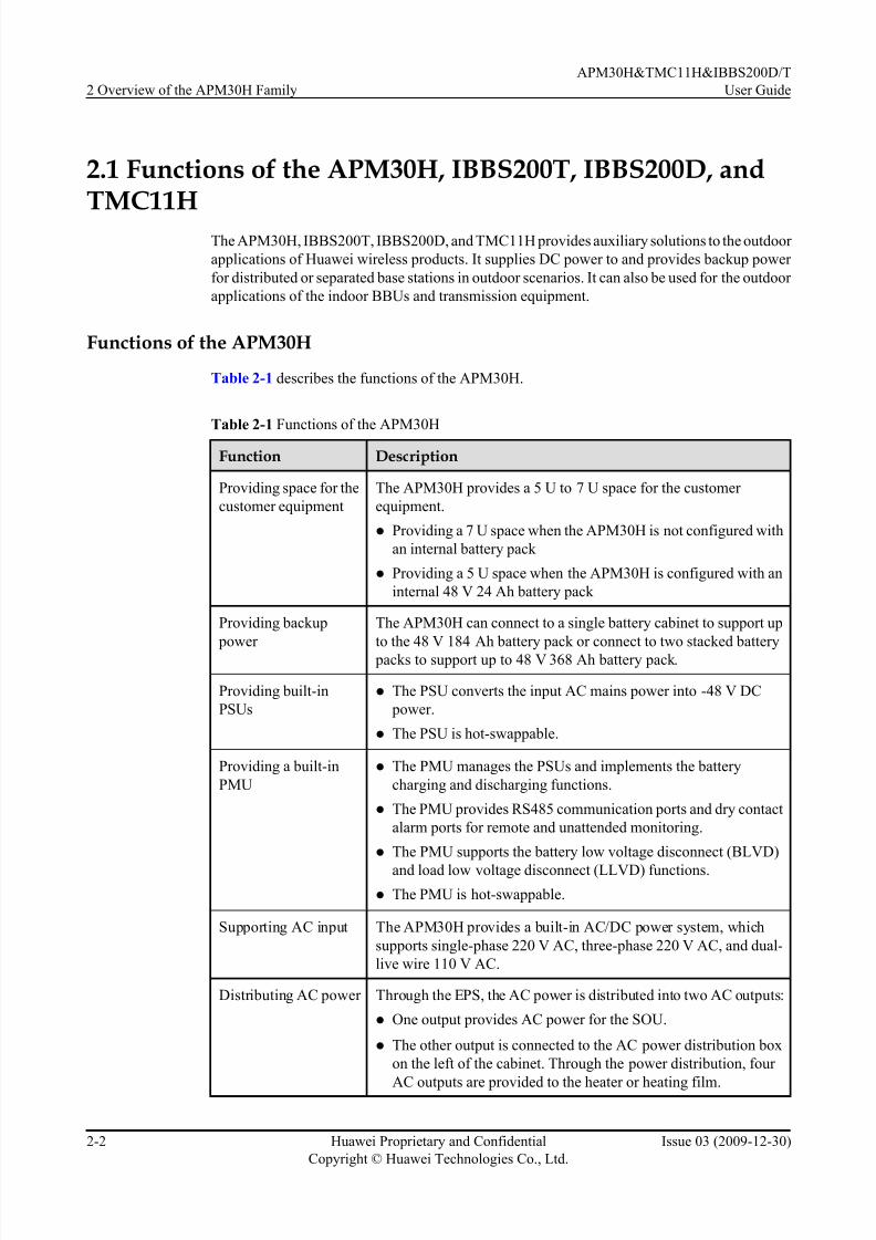
Table 2-1 describes the functions of the APM30H.
Table 2-1 Functions of the APM30H
Function Description
Providing space for the
customer equipment
The APM30H provides a 5 U to 7 U space for the customer
equipment.
l Providing a 7 U space when the APM30H is not configured with
an internal battery pack
l Providing a 5 U space when the APM30H is configured with an
internal 48 V 24 Ah battery pack
Providing backup
power
The APM30H can connect to a single battery cabinet to support up
to the 48 V 184 Ah battery pack or connect to two stacked battery
packs to support up to 48 V 368 Ah battery pack.
Providing built-in
PSUs
l The PSU converts the input AC mains power into -48 V DC
power.
l The PSU is hot-swappable.
Providing a built-in
PMU
l The PMU manages the PSUs and implements the battery
charging and discharging functions.
l The PMU provides RS485 communication ports and dry contact
alarm ports for remote and unattended monitoring.
l The PMU supports the battery low voltage disconnect (BLVD)
and load low voltage disconnect (LLVD) functions.
l The PMU is hot-swappable.
Supporting AC input The APM30H provides a built-in AC/DC power system, which
supports single-phase 220 V AC, three-phase 220 V AC, and dual-
live wire 110 V AC.
Distributing AC power Through the EPS, the AC power is distributed into two AC outputs:
l One output provides AC power for the SOU.
l The other output is connected to the AC power distribution box
on the left of the cabinet. Through the power distribution, four
AC outputs are provided to the heater or heating film.
2 Overview of the APM30H Family
APM30H&TMC11H&IBBS200D/T
User Guide
2-2 Huawei Proprietary and Confidential
Copyright © Huawei Technologies Co., Ltd.
Issue 03 (2009-12-30)

7/17/2019 Apm30 User Guide-(v200r303_03)
http://slidepdf.com/reader/full/apm30-user-guide-v200r30303 21/181
Function Description
Distributing DC power For details, see Table 2-2.
Providing surge
protection for the power supply and
signal ports
External surge protection modules for AC/DC power ports and
surge protection circuits for signal ports provide safe and reliablesurge protection and lightning protection.
Dissipating heat Heat dissipation of the APM30H is based on the heat exchanger
system that consists of a core and two air circulation fans. This can
effectively prevent dust from entering the cabinet. The APM30H
can also work with the diesel generator.
Supporting the
grounding
The grounding busbar for the cabinet and the PGND cables for the
components are all connected to the grounding bar of the cabinet.
Reporting the cabinet
type automatically
The type of the cabinet is automatically reported through the ELU.
Table 2-2 describes the DC power distribution functions of the APM30H.
Table 2-2 DC power distribution functions of the APM30H
Applic
ationScenario
DCOutput
PowerEquipment
Silkscreen onthe
OutputTerminal
ProtectionCompo
nentType Specific
ation
Quantity
DCOutputTermina
l
Distrib
uted
base
station
Six
LLVD
output
s
RRU LOAD8
to
LOAD13
MCB 20 A 6 Easy
power
receptacle
(pressfit
type)
connector Nine
BLV
D
output
s
TMC TMC 25 A 1
FAN unit LOAD0 Fuse 15 A 1
BBU LOAD1and
LOAD2
2
TEC/FAN
(in the
battery
cabinet)
LOAD3 1
TM LOAD4
to
LOAD7
5 A 4
APM30H&TMC11H&IBBS200D/T
User Guide 2 Overview of the APM30H Family
Issue 03 (2009-12-30) Huawei Proprietary and Confidential
Copyright © Huawei Technologies Co., Ltd.
2-3

7/17/2019 Apm30 User Guide-(v200r303_03)
http://slidepdf.com/reader/full/apm30-user-guide-v200r30303 22/181
Application
Scenario
DC
Output
Power
Equipment
Silkscreen ontheOutput
Terminal
ProtectionComponent
Type Specification
Quantity
DCOutputTerminal
Batter
y
power
backu
p
BAT - MCB 100 A 1 Power
series 120
connector
(grey)
Separat
ed
macro
base
station
Two
LLVD
output
s
RFC - MCB 80 A 2 Power
series 120
connector
(blue)
Nine
BLV
D
output
s
TMC TMC 25 A 1 Easy
power
receptacle
(pressfit
type)
connector
FAN unit LOAD0 Fuse 15 A 1
BBU LOAD1
and
LOAD2
2
TEC/FAN
(in the
battery
cabinet)
LOAD3 1
TM LOAD4
to
LOAD7
5 A 4
Batter
y
power
backu
p
BAT - MCB 100 A 1 Power
series 120
connector
(grey)
Functions of the IBBS200T
Table 2-3 describes the functions of the IBBS200T.
2 Overview of the APM30H Family
APM30H&TMC11H&IBBS200D/T
User Guide
2-4 Huawei Proprietary and Confidential
Copyright © Huawei Technologies Co., Ltd.
Issue 03 (2009-12-30)

7/17/2019 Apm30 User Guide-(v200r303_03)
http://slidepdf.com/reader/full/apm30-user-guide-v200r30303 23/181
Table 2-3 Functions of the IBBS200T
Function Description
Providing
backup power
l When configured with 48 V 50 Ah batteries, the IBBS200T can provide
DC backup power of 48 V 50 Ah or 48 V 100 Ah (by housing two battery packs).
l When configured with 48 V 92 Ah batteries, the IBBS200T can provide
DC backup power of 48 V 92 Ah or 48 V 184 Ah (by housing two battery
packs).
Reporting the
cabinet type
automatically
The type of the cabinet is automatically reported through the ELU.
Providing a
built-in TEC
cooler
The TEC cooler enables the IBBS200T to adapt to high ambient temperature
and maintains a proper range of temperature for the cabinet.
Monitoring the
alarm signals
in a centralized
way
The CMUA collects the alarm signals from the components such as the door
status sensor, temperature sensor of the battery, fan, and smoke sensor.
Then, the CMUA transmits the alarm signals to the base station.
Functions of the IBBS200D
Table 2-4 describes the functions of the IBBS200D.
Table 2-4 Functions of the IBBS200D
Function Description
Providing
backup power
l When configured with 48 V 50 Ah batteries, the IBBS200D can provide
DC backup power of 48 V 50 Ah or 48 V 100 Ah (by housing two battery
packs).
l When configured with 48 V 92 Ah batteries, the IBBS200D can provide
DC backup power of 48 V 92 Ah or 48 V 184 Ah (by housing two battery
packs).
Reporting thecabinet type
automatically
The type of the cabinet is automatically reported through the ELU.
Providing
built-in fans
The fans in the cabinet speed up the circulation of the air inside and outside
the cabinet and keep the temperature in the cabinet in a proper range
Monitoring the
alarm signals
in a centralized
way
The CMUA collects the alarm signals from the components such as the door
status sensor, temperature sensor of the battery, fan, and smoke sensor.
Then, the CMUA transmits the alarm signals to the base station.
APM30H&TMC11H&IBBS200D/T
User Guide 2 Overview of the APM30H Family
Issue 03 (2009-12-30) Huawei Proprietary and Confidential
Copyright © Huawei Technologies Co., Ltd.
2-5

7/17/2019 Apm30 User Guide-(v200r303_03)
http://slidepdf.com/reader/full/apm30-user-guide-v200r30303 24/181
Functions of the TMC11H
Table 2-5 describes the functions of the TMC11H.
Table 2-5 Functions of the TMC11HFunction Description
Providing -48
V DC power
The TMC11H is configured with a built-in DCDU-03 and performs the
following functions:
l Supporting one -48 V DC input
l Providing nine -48 V DC outputs (LOAD0 to LOAD8)
Providing
space for
customer
equipment
l The TMC11H provides 11 U space for customer equipment.
l If the heater is installed, the TMC11H provides 10 U space for customer
equipment.
Reporting
alarms
The TMC11H provides the following two dry contact alarm ports for remote
and unmanned monitoring: One of the dry contact alarm ports is connected
to the door status sensor. An open circuit indicates that the connection is
faulty, whereas a closed circuit indicates that the connection is normal.
Reporting the
cabinet type
automatically
The type of the cabinet is automatically reported through the ELU.
2.2 Application Scenarios of the APM30H Family
The APM30H family can work with the distributed or separated base stations, meeting the
requirements in different scenarios.
APM30H Working with a Distributed Base Station
The scenario in which the APM30H works with a distributed base station is as follows:
l The APM30H provides the 7 U space for the BBU and transmission equipment. The built-
in power system of the APM30H supplies -48 V DC power to the distributed base station
and transmission equipment and charges the batteries in the battery cabinet.l When the mains power is unavailable, the batteries in the IBBS200T supplies -48 V DC
power to the distribution base station and transmission equipment.
Figure 2-1 shows the scenario in which the APM30H stacked on the battery cabinet works with
a distributed base station.
2 Overview of the APM30H Family
APM30H&TMC11H&IBBS200D/T
User Guide
2-6 Huawei Proprietary and Confidential
Copyright © Huawei Technologies Co., Ltd.
Issue 03 (2009-12-30)

7/17/2019 Apm30 User Guide-(v200r303_03)
http://slidepdf.com/reader/full/apm30-user-guide-v200r30303 25/181
Figure 2-1 APM30H (stacked on the battery cabinet) working with a distributed base station
NOTE
When the APM30H works with a distributed base station, it can be configured with the IBBS200D or
IBBS200T. The Figure 2-1 takes the IBBS200D as an example.
APM30H working with a separated macro base station
The scenario in which the APM30H works with a separated macro base station is described as
follows:
l The APM30H provides a 7 U space for the BBU and transmission equipment. The built-
in power system of the APM30H supplies -48 V DC power to the BBU, RFU, and
transmission equipment and charges the batteries in the battery cabinet.
l The APM30H reports the alarms related to fans, door status, DCDU, and batteries in the
battery cabinet.
Figure 2-2 shows the scenarios in which the APM30H works with separated macro base stations.
APM30H&TMC11H&IBBS200D/T
User Guide 2 Overview of the APM30H Family
Issue 03 (2009-12-30) Huawei Proprietary and Confidential
Copyright © Huawei Technologies Co., Ltd.
2-7

7/17/2019 Apm30 User Guide-(v200r303_03)
http://slidepdf.com/reader/full/apm30-user-guide-v200r30303 26/181
Figure 2-2 APM30H working with a separated macro base station
NOTE
When the APM30H works with a separated macro base station, it can be configured with the IBBS200D
or IBBS200T. Figure 2-1 takes the IBBS200D as an example.
2.3 Technical Specifications of the APM30H Family
The technical specifications of the APM30H family consist of the electrical specifications,
engineering specifications, surge protection specifications, and specifications concerning the
environmental requirements.
2.3.1 Electrical Specifications of the APM30H and TMC11H
The electrical specifications involve AC input, DC output, protection, and Permissible heat
consumption in the cabinet.
2.3.2 Engineering Specifications of the APM30H, IBBS200T, IBBS200D, and TMC11H
The engineering specifications involve the cabinet weight, cabinet dimensions, base dimensions,
space for the customer equipment, space for cabling and maintenance space in front of the
cabinet, and installation options.
2.3.3 Surge Protection Specifications of the APM30H
The surge protection specifications of the APM30H involve the surge protection for the AC
input port, surge protection for the DC output port, and surge protection for signal ports.
2.3.4 Environmental Requirements of the APM30H, IBBS200T, IBBS200D, and TMC11H
The environmental requirements involve the operating temperature, relative humidity, altitude,and storage temperature.
2 Overview of the APM30H Family
APM30H&TMC11H&IBBS200D/T
User Guide
2-8 Huawei Proprietary and Confidential
Copyright © Huawei Technologies Co., Ltd.
Issue 03 (2009-12-30)

7/17/2019 Apm30 User Guide-(v200r303_03)
http://slidepdf.com/reader/full/apm30-user-guide-v200r30303 27/181
2.3.1 Electrical Specifications of the APM30H and TMC11H
The electrical specifications involve AC input, DC output, protection, and Permissible heat
consumption in the cabinet.
Electrical Specifications of the APM30H
Table 2-6 describes the electrical specifications of the APM30H.
Table 2-6 Electrical specifications of the APM30H
Item Specification
AC
input
Typical
input
voltage
200 V AC to 240 V AC (single-phase 220 V AC)
200 V AC to 240 V AC or 346 V AC to 415 V AC (three-phase 220 V
AC or 380 V AC)
100 V AC to 120 V AC or 200 V AC to 240 V AC (dual-live-wire 110
V AC)
120 V AC to 127 V AC or 208 V AC to 220 V AC (dual-live-wire 120
V AC)
Operating
voltage
range
176 V AC to 290 V AC (single-phase 220 V AC)
176 V AC to 290 V AC or 304 V AC to 500 V AC (three-phase 220 V
AC)
90 V AC to 135 V AC or 180 V AC to 270 V AC (dual-live-wire 110 V
AC)
105 V AC to 150 V AC or 176 V AC to 260 V AC (dual-live-wire 120
V AC)
Frequenc
y of the
input
voltage
50 Hz or 60 Hz
Maximu
m input
current
16 A (three-phase 220 V AC or 380 V AC)
40 A (dual-live-wire 110 V AC, dual-live-wire 120 V AC, or single-phase
220 V AC)
Input
mode
l Three-phase 220 V AC or 380 V AC
l Dual-live-wire 110 V AC
l Dual-live-wire 120 V AC
l Single-phase 220 V AC
APM30H&TMC11H&IBBS200D/T
User Guide 2 Overview of the APM30H Family
Issue 03 (2009-12-30) Huawei Proprietary and Confidential
Copyright © Huawei Technologies Co., Ltd.
2-9

7/17/2019 Apm30 User Guide-(v200r303_03)
http://slidepdf.com/reader/full/apm30-user-guide-v200r30303 28/181
Item Specification
AC input
power
The AC input power varies according to AC load.
l When the PSU is configured:≤ 5,274 W
l When the PSU, heater, and heating film are configured:≤ 6,074 W
l When the PSU, heater, heating film, and SOU are configured:≤ 8,274
W
DC
outp
ut
Output
voltage
range
-43.2 V DC to -57 V DC
Output
current
range
l When two PSUs are configured: 0 A to 60 A
l When three PSUs are configured: 0 A to 90 A
Typicaloutput
voltage
-53.5 V DC
Number
of DC
outputs
The number of DC outputs varies according to application scenario.
l When working with a distributed base station: 16 DC outputs
l When working with a separated base station: 12 DC outputs
DC
output
power
≤ 3,200 W (two active PSUs and + one standby PSU)
Protection
Input protectio
n
l Overvoltage protection: The system generates an alarm when the inputvoltage reaches the AC overvoltage alarm threshold, which is 280 V
by default.
l Undervoltage protection: The system generates an alarm when the
input voltage is lower than the AC undervoltage alarm threshold,
which is 180 V by default.
Output
protectio
n
l Overvoltage protection: The system generates an alarm when the
busbar voltage reaches the DC overvoltage alarm threshold, which is
-58 V by default.
l Undervoltage protection: The system generates an alarm when the
busbar voltage is lower than the DC undervoltage alarm threshold,which is -45 V by default.
l Overcurrent protection and short-circuit protection
Permissible heat
consumption in
the cabinet
≤ 700 W
Electrical specifications of the TMC11H
Table 2-7 describes the electrical specifications of the TMC11H.
2 Overview of the APM30H Family
APM30H&TMC11H&IBBS200D/T
User Guide
2-10 Huawei Proprietary and Confidential
Copyright © Huawei Technologies Co., Ltd.
Issue 03 (2009-12-30)

7/17/2019 Apm30 User Guide-(v200r303_03)
http://slidepdf.com/reader/full/apm30-user-guide-v200r30303 29/181
Table 2-7 Electrical specifications of the TMC11H
Item Specification
DC input Input voltage
range
-38.4 V DC to -57 V DC
Typical input
voltage
-53.5 V DC
Maximum input
current
21 A
Input mode -48 V DC power input, supporting M6 2-hole OT
terminals
DC input power ≤ 800 W
DC output DC distribution Nine -48 V DC outputs: LOAD0 to LOAD8 for the
customer equipment
NOTEWhen configured with different types of DCDU-03, the
TMC11H can meet different current requirements.
Typical output
voltage
-48 V DC
Protection Overcurrent and short-circuit protection for DC power
distribution
Permissible heat consumption in
the cabinet
≤ 700 W
2.3.2 Engineering Specifications of the APM30H, IBBS200T,IBBS200D, and TMC11H
The engineering specifications involve the cabinet weight, cabinet dimensions, base dimensions,
space for the customer equipment, space for cabling and maintenance space in front of the
cabinet, and installation options.
Engineering Specifications of the APM30H
Table 2-8 describes the engineering specifications of the APM30H.
APM30H&TMC11H&IBBS200D/T
User Guide 2 Overview of the APM30H Family
Issue 03 (2009-12-30) Huawei Proprietary and Confidential
Copyright © Huawei Technologies Co., Ltd.
2-11

7/17/2019 Apm30 User Guide-(v200r303_03)
http://slidepdf.com/reader/full/apm30-user-guide-v200r30303 30/181
Table 2-8 Engineering specifications of the APM30H
Item Specification Remarks
Weight ≤ 72 kg Total weight of the equipment
l Including the cabinet frame, inner air circulation fan, outer air circulation fan, core of
the heart exchanger, EPS4890B-4830A, and
cables
l Excluding the BBU, transmission equipment of
the customer, PMU, and PSU
≤ 91 kg Weight of the cabinet in full configuration
l Including the equipment, one PMU, three
PSUs, and one BBU
l Excluding the transmission equipment of the
customer
Dimensions of
the cabinet
(width x height x
depth)
600 mm x 700 mm x
480 mm
The base is not included.
Dimensions of
the base (width x
height x depth)
600 mm x 200 mm x
434 mm
-
Space for the
customer
equipment
(width x height x
depth)
482.6 mm x 311.15
mm x 310 mm (19-
inch x 7 U x 310 mm
or 290 mm)
l The depth refers to the spacing between the
column and the rear side of the cabinet.
l The depth of the 3 U space at the bottom of the
cabinet is 290 mm, and heat dissipation from
the back of the customer equipment is not
supported.
Space for cabling
and maintenance
space in front of
the cabinet
≥ 70 mm -
Installation
option
The APM30H can
be installed on the
ground, on a wall, or on a pole, or stacked
with the RFC or the
IBBS200D/
IBBS200T.
When installed in stack mode, the APM30H
should be placed on the RFC or the IBBS200D/
IBBS200T.
Engineering Specifications of the IBBS200T
Table 2-9 describes the engineering specifications of the IBBS200T.
2 Overview of the APM30H Family
APM30H&TMC11H&IBBS200D/T
User Guide
2-12 Huawei Proprietary and Confidential
Copyright © Huawei Technologies Co., Ltd.
Issue 03 (2009-12-30)

7/17/2019 Apm30 User Guide-(v200r303_03)
http://slidepdf.com/reader/full/apm30-user-guide-v200r30303 31/181
Table 2-9 Engineering specifications of the IBBS200T
Item Specification Remarks
Cabinet weight ≤ 70 kg Built-in batteries are not
configured.
Battery weight Supporting front maintenance of
48 V 50 Ah or 48 V 92 Ah batteries
l A single 12 V 50 Ah battery:
21.5 kg
l A single 12 V 92 Ah battery:
33.5 kg
NOTEThe batteries of different
manufacturers may have different
weights. The following description is
based on common batteries.
Two 48 V 92 Ah battery packs can
be connected in parallel to provide
48 V 184 Ah backup power.
Dimensions of the
cabinet (width x
height x depth)
600 mm x 700 mm x 480 mm Excluding the 206 mm that is
stretched out of the cabinet on the
front door.
Base dimensions
(width x height x
depth)
600 mm x 200 mm x 480 mm -
Installation option The IBBS200T can be installed on
the ground or stacked with the
TMC11H or APM30H.
When installed in stack mode, the
IBBS200T should be placed below
the TMC11H or APM30H.
Engineering Specifications of the IBBS200D
Table 2-10 describes the engineering specifications of the IBBS200D.
Table 2-10 Engineering specifications of the IBBS200D
Item Specification Remarks
Cabinet weight ≤ 50 kg Built-in batteries are not
configured.
APM30H&TMC11H&IBBS200D/T
User Guide 2 Overview of the APM30H Family
Issue 03 (2009-12-30) Huawei Proprietary and Confidential
Copyright © Huawei Technologies Co., Ltd.
2-13
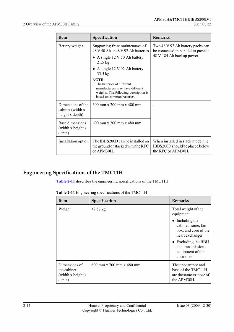
7/17/2019 Apm30 User Guide-(v200r303_03)
http://slidepdf.com/reader/full/apm30-user-guide-v200r30303 32/181
Item Specification Remarks
Battery weight Supporting front maintenance of
48 V 50 Ah or 48 V 92 Ah batteries
l A single 12 V 50 Ah battery:21.5 kg
l A single 12 V 92 Ah battery:
33.5 kg
NOTEThe batteries of different
manufacturers may have different
weights. The following description is
based on common batteries.
Two 48 V 92 Ah battery packs can
be connected in parallel to provide
48 V 184 Ah backup power.
Dimensions of the
cabinet (width x
height x depth)
600 mm x 700 mm x 480 mm -
Base dimensions
(width x height x
depth)
600 mm x 200 mm x 480 mm
Installation option The IBBS200D can be installed on
the ground or stacked with the RFC
or APM30H.
When installed in stack mode, the
IBBS200D should be placed below
the RFC or APM30H.
Engineering Specifications of the TMC11HTable 2-11 describes the engineering specifications of the TMC11H.
Table 2-11 Engineering specifications of the TMC11H
Item Specification Remarks
Weight ≤ 57 kg Total weight of the
equipment
l Including the
cabinet frame, fan
box, and core of the
heart exchanger
l Excluding the BBU
and transmission
equipment of the
customer
Dimensions of
the cabinet
(width x height x
depth)
600 mm x 700 mm x 480 mm The appearance and
base of the TMC11H
are the same as those of
the APM30H.
2 Overview of the APM30H Family
APM30H&TMC11H&IBBS200D/T
User Guide
2-14 Huawei Proprietary and Confidential
Copyright © Huawei Technologies Co., Ltd.
Issue 03 (2009-12-30)

7/17/2019 Apm30 User Guide-(v200r303_03)
http://slidepdf.com/reader/full/apm30-user-guide-v200r30303 33/181
Item Specification Remarks
Base dimensions
(width x height x
depth)
600 mm x 200 mm x 480 mm
Space for the
customer
equipment (width
x height x depth)
482.6 mm x 488.95 mm x 310 mm (19-inch x
11 U x 310 mm)
l The depth refers to
the spacing between
the column and the
rear side of the
cabinet.
l The depth of the 3 U
space at the bottom
of the cabinet is 290
mm, and heat
dissipation from the
back of thecustomer
equipment is not
supported.
Space for cabling
and maintenance
space in front of
the cabinet
≥ 70 mm -
Installation
option
The TMC11H can be installed on the ground or
on a pole or stacked with the RFC or the
IBBS200D/IBBS200T.
When installed in
stack mode, the
TMC11H should be
placed on the RFC or
the IBBS200D/
IBBS200T.
2.3.3 Surge Protection Specifications of the APM30H
The surge protection specifications of the APM30H involve the surge protection for the AC
input port, surge protection for the DC output port, and surge protection for signal ports.
Surge Protection Specifications of the APM30H
Table 2-12 describes the surge protection specifications of the APM30H.
Table 2-12 Surge protection specifications of the APM30H
Item Specification
Surge protection for the AC
input port
In differential mode:
l Nominal through-current capacity In (8/20 µs) 25 kA
l Maximum through-current capacity Imax (8/20 µs) 60 kA
APM30H&TMC11H&IBBS200D/T
User Guide 2 Overview of the APM30H Family
Issue 03 (2009-12-30) Huawei Proprietary and Confidential
Copyright © Huawei Technologies Co., Ltd.
2-15

7/17/2019 Apm30 User Guide-(v200r303_03)
http://slidepdf.com/reader/full/apm30-user-guide-v200r30303 34/181
Item Specification
In common mode:
l Nominal through-current capacity In (8/20 µs) 25 kA
l Maximum through-current capacity Imax (8/20 µs) 60 kA
Surge protection for the DC
output port
l In differential mode (8/20 µs): 10 kA
l In common mode (8/20 µs): 15 kA
The DC output corresponds to the secondary load.
NOTEThe surge protection class for the shielding layer of the RRU power
cable is 40 kA.
Surge protection for signal
ports
E1/T1 port:
l In differential mode (8/20 µs): 3 kA
l In common mode (8/20 µs): 5 kA
FE port:
l In differential mode (8/20 µs): 1 kA
l In common mode (8/20 µs): 2 kA
2.3.4 Environmental Requirements of the APM30H, IBBS200T,IBBS200D, and TMC11H
The environmental requirements involve the operating temperature, relative humidity, altitude,
and storage temperature.
Environmental Requirements of the APM30H
The APM30H can be used outdoors. Table 2-13 describes the environmental requirements of
the APM30H.
Table 2-13 Environmental requirements of the APM30H
Item Specification Remarks
Operating
temperatur
e
-40oC to +50oC (with solar radiation
of 1,120 ± 10% W/m2)
When the APM30H works under
-20oC, a heater needs to be configured.
NOTEThe operating temperature for configuring
a heater refers to the average of the local
lowest temperatures for a month in a year.
Relative
humidity
5% RH to 100% RH -
2 Overview of the APM30H Family
APM30H&TMC11H&IBBS200D/T
User Guide
2-16 Huawei Proprietary and Confidential
Copyright © Huawei Technologies Co., Ltd.
Issue 03 (2009-12-30)

7/17/2019 Apm30 User Guide-(v200r303_03)
http://slidepdf.com/reader/full/apm30-user-guide-v200r30303 35/181
Item Specification Remarks
Altitude -60 m to +4,000 m Above the altitude of 3,000 m, the
maximum operating temperature
decreases by 1
o
C each time the altitudeincreases by 100 m.
Wind
speed
≤ 67 m/s -
Storage
temperatur
e
-40oC to +70oC -
Dustproof
and
waterproof
specification
IP55 -
Noise - Complying with the ETS 300 753 4.1E
standard (in a rural scenario)
Environmental Requirements of the IBBS200T
The IBBS200T can be used outdoors. Table 2-14 describes the environmental requirements of
the IBBS200T.
Table 2-14 Environmental requirements of the IBBS200T
Item Specification Remarks
Operating
temperatur
e
-20oC to +50oC (with solar radiation
of not more than 1,120 ± 10% W/m2)
-
Relative
humidity
5% RH to 100% RH -
Altitude -60 m to +4,000 m Above the altitude of 3,000 m, the
maximum operating temperaturedecreases by 1oC each time the altitude
increases by 100 m.
Wind
speed
≤ 67 m/s -
Storage
temperatur
e
-40oC to +70oC -
APM30H&TMC11H&IBBS200D/T
User Guide 2 Overview of the APM30H Family
Issue 03 (2009-12-30) Huawei Proprietary and Confidential
Copyright © Huawei Technologies Co., Ltd.
2-17

7/17/2019 Apm30 User Guide-(v200r303_03)
http://slidepdf.com/reader/full/apm30-user-guide-v200r30303 36/181
Item Specification Remarks
Dustproof
and
waterproof
specificati
on
IP55 -
Noise - Complying with the ETS 300 753 4.1E
standard (in an urban scenario)
Environmental Requirements of the IBBS200D
The IBBS200D can be used outdoors. Table 2-15 describes the environmental requirements of
the IBBS200D.
Table 2-15 Environmental requirements of the IBBS200D
Item Specification Remarks
Operating
temperatur
e
-40oC to +45oC (with solar radiation
of not more than 1,120 ± 10% W/m2)
When the IBBS200D works under
-200C, a heater film needs to be
configured.
NOTEThe operating temperature for configuring
a heating film refers to the average of the
local lowest temperatures recorded for a
month in a year.
Relative
humidity
5% RH to 100% RH -
Altitude -60 m to +4,000 m Above the altitude of 3,000 m, the
maximum operating temperature
decreases by 1oC each time the altitude
increases by 100 m.
Wind
speed
≤ 67 m/s -
Storage
temperatur
e
-40oC to +70oC -
Dustproof
and
waterproof
specificati
on
IP35 -
Noise - Complying with the ETS 300 753 4.1E
standard (in a rural scenario)
2 Overview of the APM30H Family
APM30H&TMC11H&IBBS200D/T
User Guide
2-18 Huawei Proprietary and Confidential
Copyright © Huawei Technologies Co., Ltd.
Issue 03 (2009-12-30)

7/17/2019 Apm30 User Guide-(v200r303_03)
http://slidepdf.com/reader/full/apm30-user-guide-v200r30303 37/181
Environmental Requirements of the TMC11H
The TMC11H can be used outdoors. The environmental requirements of the TMC11H are the
same as those of the APM30H. For details, see Table 2-13.
APM30H&TMC11H&IBBS200D/T
User Guide 2 Overview of the APM30H Family
Issue 03 (2009-12-30) Huawei Proprietary and Confidential
Copyright © Huawei Technologies Co., Ltd.
2-19

7/17/2019 Apm30 User Guide-(v200r303_03)
http://slidepdf.com/reader/full/apm30-user-guide-v200r30303 38/181
7/17/2019 Apm30 User Guide-(v200r303_03)
http://slidepdf.com/reader/full/apm30-user-guide-v200r30303 39/181
3 Overview of the APM30H
About This Chapter
This describes the exterior, structure, and components of the APM30H.
3.1 Exterior of the APM30H
The APM30H is brightly colored and elegantly designed. It is small in size and easy to transport.
3.2 Structure of the APM30H
The APM30H has a highly integrated and modular structure design. Thus, the cabinet is easy to
operate and maintain.
3.3 Cable Connections of the APM30HThe cables of the APM30H are power cables and signal cables.
3.4 APM30H Components
The components of the APM30H consist of the fan box, power system (AC/DC), power system
(DC/DC), core of the heat exchanger, junction box, Electronic Label Unit (ELU), heater, and
Service Outlet Unit (SOU). The heater and the SOU are optional.
3.5 APM30H Cables
The APM30H cables consist of the PGND cable, input power cable, environment monitoring
signal cable, and monitoring signal cable f or the PMU.
APM30H&TMC11H&IBBS200D/T
User Guide 3 Overview of the APM30H
Issue 03 (2009-12-30) Huawei Proprietary and Confidential
Copyright © Huawei Technologies Co., Ltd.
3-1

7/17/2019 Apm30 User Guide-(v200r303_03)
http://slidepdf.com/reader/full/apm30-user-guide-v200r30303 40/181
3.1 Exterior of the APM30H
The APM30H is brightly colored and elegantly designed. It is small in size and easy to transport.
Figure 3-1 shows exterior of the APM30H.
Figure 3-1 Exterior of the APM30H
3.2 Structure of the APM30H
The APM30H has a highly integrated and modular structure design. Thus, the cabinet is easy tooperate and maintain.
Figure 3-2 shows the internal structure of the APM30H.
3 Overview of the APM30H
APM30H&TMC11H&IBBS200D/T
User Guide
3-2 Huawei Proprietary and Confidential
Copyright © Huawei Technologies Co., Ltd.
Issue 03 (2009-12-30)

7/17/2019 Apm30 User Guide-(v200r303_03)
http://slidepdf.com/reader/full/apm30-user-guide-v200r30303 41/181
Figure 3-2 Internal structure of the APM30H
(1) HPMI (2) Inner air circulation fan (3) CMUA
(4) PSU (5) Door status sensor (6) ELU
(7) EPS (8) Outer air circulation fan (9) Heat exchanger
(10) Junction box (11)PMU -
As shown in the preceding picture, the APM30H provides space as follows:
l If the heater or the SOU is not installed, the APM30H provides a 7 U space for the customer
equipment.
l If the heater or the SOU is installed, the APM30H provides a 6 U space for the customer
equipment.
l The APM30H provides a 1 U space at the top for operation and maintenance of the fan box.
3.3 Cable Connections of the APM30H
The cables of the APM30H are power cables and signal cables.
Cable Connections of the APM30H Working with a Distributed Base Station
Figure 3-3 shows the cable connections of the APM30H working with a distributed base station.
APM30H&TMC11H&IBBS200D/T
User Guide 3 Overview of the APM30H
Issue 03 (2009-12-30) Huawei Proprietary and Confidential
Copyright © Huawei Technologies Co., Ltd.
3-3

7/17/2019 Apm30 User Guide-(v200r303_03)
http://slidepdf.com/reader/full/apm30-user-guide-v200r30303 42/181
Figure 3-3 Cable connections of the APM30H working with a distributed base station
(1) 3.5.9 Environment Monitoring
Signal Cable
(2) 3.5.7 APM30H Door Status
Monitoring Cable
(3) 3.5.10 Monitoring Signal
Transfer Cable
(4) 3.5.6 ELU Signal Cable (5) 3.5.8 Transfer Cable for the
Fan on the Front Door
(6) 3.5.5 Power Cable for the Fan
Box in the APM30H
(7) Power cables for the batteries (8) Input power cable for the
junction box
(9) Cable for the fan on the front
door
(10) Power cable for the heater or
heating film
- -
Cable Connections of the APM30H Working with a Separated Macro Base Station
Figure 3-4 shows the cable connections of the APM30H working with a separated macro base
station.
3 Overview of the APM30H
APM30H&TMC11H&IBBS200D/T
User Guide
3-4 Huawei Proprietary and Confidential
Copyright © Huawei Technologies Co., Ltd.
Issue 03 (2009-12-30)

7/17/2019 Apm30 User Guide-(v200r303_03)
http://slidepdf.com/reader/full/apm30-user-guide-v200r30303 43/181
Figure 3-4 Cable connections of the APM30H working with a separated macro base station
(1) 3.5.9 Environment Monitoring
Signal Cable
(2) 3.5.7 APM30H Door Status
Monitoring Cable
(3) 3.5.10 Monitoring Signal
Transfer Cable
(4) 3.5.6 ELU Signal Cable (5) 3.5.8 Transfer Cable for the
Fan on the Front Door
(6) 3.5.5 Power Cable for the Fan
Box in the APM30H
(7) Power cables for RFC1 (8) Power cables for RFC2 (9) Power cables for the batteries
(10) Input power cable for the
junction box
(11) Cable for the fan on the front
door
(12) Power cable for the heater or
heating film
3.4 APM30H Components
The components of the APM30H consist of the fan box, power system (AC/DC), power system
(DC/DC), core of the heat exchanger, junction box, Electronic Label Unit (ELU), heater, and
Service Outlet Unit (SOU). The heater and the SOU are optional.
3.4.1 Fan Box
The fan box consists of the fan subrack, fans, HPMI, and CMUA.
3.4.2 AC/DC Power System
The AC/DC power system consists of the EPS, PMU, and PSU (AC/DC).
3.4.3 DC/DC Power System
The DC/DC power system converts +24 V DC power into -48 V DC power.
3.4.4 Core of the Heat Exchanger
The core of the heat exchanger extends the area for the exchange of the air inside and outsidethe APM30H cabinet, speeding up the air circulation and effectively decreasing the working
APM30H&TMC11H&IBBS200D/T
User Guide 3 Overview of the APM30H
Issue 03 (2009-12-30) Huawei Proprietary and Confidential
Copyright © Huawei Technologies Co., Ltd.
3-5

7/17/2019 Apm30 User Guide-(v200r303_03)
http://slidepdf.com/reader/full/apm30-user-guide-v200r30303 44/181
temperature of the cabinet. In addition, the core of the heat exchanger keeps the dust away from
the cabinet.
3.4.5 Junction Box
The junction box divides one AC input into four AC outputs. The AC outputs are used for the
SOU and multiple heating films or heaters.
3.4.6 ELU
The Electronic Label Unit (ELU) automatically reports the information about the cabinet type,
facilitating fast troubleshooting.
3.4.7 Door Status Sensor
The door status sensor monitors the opening and closing of the front door of the cabinet.
3.4.8 Heater
The heater pr ovides the proper operating temperature for the customer equipment working in
low temperature in the cabinet. The heater is optional.
3.4.9 SOUThe Service Outlet Unit (SOU) feeds AC power to the customer equipment. The SOU is optional.
3.4.1 Fan Box
The fan box consists of the fan subrack, fans, HPMI, and CMUA.
Figure 3-5 shows the fan box.
Figure 3-5 Fan Box
(1) Fans (2) Fan subrack (3) CMUA (4) HPMI
FansFans are installed in the fan box of the cabinet. They dissipate the heat for the cabinet.
Exterior
Figure 3-6 shows a fan.
3 Overview of the APM30H
APM30H&TMC11H&IBBS200D/T
User Guide
3-6 Huawei Proprietary and Confidential
Copyright © Huawei Technologies Co., Ltd.
Issue 03 (2009-12-30)

7/17/2019 Apm30 User Guide-(v200r303_03)
http://slidepdf.com/reader/full/apm30-user-guide-v200r30303 45/181
Figure 3-6 Fan
Technical Specifications
Table 3-1 describes the technical specifications of the fan.
Table 3-1 Technical specifications of the fan
Item Specification
Dimensions (Diameter x Height) 175 mm x 69 mm
Length of the leadNOTE
The lead is delivered with the fan and is used for
power input and monitoring.
450 mm
Definition of pins 1 to 4 of the lead l Pin 1: red, connected to the positive pole
of the power supply
l Pin 2: yellow, connected to the input of the
speed-adjusting signals
l Pin 3: blue, connected to the output of the
alarm or speed signals
l
Pin 4: black, connected to the negative poleof the power supply
NOTEThe colors of the cables of the fans vary according
to the manufacturer.
Rated voltage -48 V
Operating voltage range -36 V to -57 V
Rated current 0.52 A
Maximum current 0.77 A
Rated power 24.96 W
APM30H&TMC11H&IBBS200D/T
User Guide 3 Overview of the APM30H
Issue 03 (2009-12-30) Huawei Proprietary and Confidential
Copyright © Huawei Technologies Co., Ltd.
3-7

7/17/2019 Apm30 User Guide-(v200r303_03)
http://slidepdf.com/reader/full/apm30-user-guide-v200r30303 46/181
Item Specification
Maximum power 36.96 W
Rated speed 3100 r/min
Speed-adjusting mode PWM mode
HPMI
The Hert Power Monitoring Interface unit (HPMI) transfers the power monitoring signals and
provides ports for the input and output of various alarm signals.
Exterior
Figure 3-7 shows the HPMI.
Figure 3-7 HPMI
Ports
Figure 3-8 shows the ports on the panel of the HPMI, and Table 3-2 describes the ports on the
panel of the HPMI.
Figure 3-8 Ports on the panel of the HPMI
PMU_DB50 GATE TEM_BAT1 SMOKE WATER TEM_HUMOUT0 O UT1 IN0 IN1 IN2 FUSE+- +- +- +- +- +-
IN3 IN4+- +-
Table 3-2 Ports on the panel of the HPMI
Port Function
PMU_DB50 Transferring the monitoring signals of the
PMU
OUT0, OUT1 Transmitting two Boolean outputs
IN0, IN1, and IN2 Receiving three Boolean inputs
FUSE Detecting the fuse alarm signals
3 Overview of the APM30H
APM30H&TMC11H&IBBS200D/T
User Guide
3-8 Huawei Proprietary and Confidential
Copyright © Huawei Technologies Co., Ltd.
Issue 03 (2009-12-30)

7/17/2019 Apm30 User Guide-(v200r303_03)
http://slidepdf.com/reader/full/apm30-user-guide-v200r30303 47/181
Port Function
GATE Receiving the door status alarm input signals
IN3, IN4 Receiving two Boolean inputs
TEM_BAT1 Receiving the battery temperature monitoring
input
SMOKE Receiving the smoke alarm input
WATER Receiving the water damage alarm input
TEM_HUM Receiving the temperature and humidity
alarm input
CMUA
This describes the Central Monitoring Unit type A (CMUA).
Functions
The CMUA implements the following functions:
l Automatically adjusts and controls the temperature of the cabinet in different temperature
control modes.
l Reserves three ports for Boolean inputs and detects the Boolean alarms in the cabinet. The
remote detection, however, is not supported.l Provides an RJ-45 port for the ELU and monitors the information about the cabinet type.
Ports
Figure 3-9 shows the ports on the CMUA.
Figure 3-9 Ports on the CMUA
(1) TEM/TEM_BAT port (2) COM_OUT port (3) COM_IN port (4) LEDs
(5) ELU port (6) GATE port (7) IN0 port (8) IN1 port
(9) IN2 port (10) SMOKE port (11) FAN_EXT port (12) PWR port
APM30H&TMC11H&IBBS200D/T
User Guide 3 Overview of the APM30H
Issue 03 (2009-12-30) Huawei Proprietary and Confidential
Copyright © Huawei Technologies Co., Ltd.
3-9
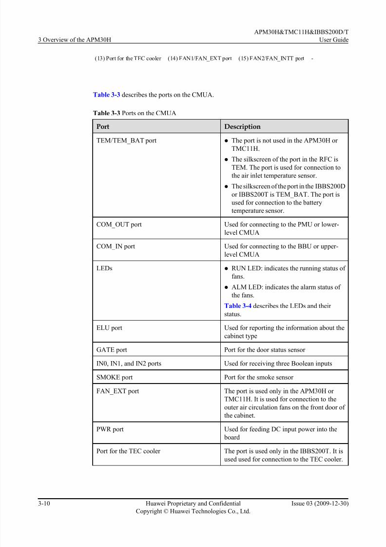
7/17/2019 Apm30 User Guide-(v200r303_03)
http://slidepdf.com/reader/full/apm30-user-guide-v200r30303 48/181
(13) Port for the TEC cooler (14) FAN1/FAN_EXT port (15) FAN2/FAN_INTT port -
Table 3-3 describes the ports on the CMUA.
Table 3-3 Ports on the CMUA
Port Description
TEM/TEM_BAT port l The port is not used in the APM30H or
TMC11H.
l The silkscreen of the port in the RFC is
TEM. The port is used for connection to
the air inlet temperature sensor.
l The silkscreen of the port in the IBBS200D
or IBBS200T is TEM_BAT. The port is
used for connection to the battery
temperature sensor.
COM_OUT port Used for connecting to the PMU or lower-
level CMUA
COM_IN port Used for connecting to the BBU or upper-
level CMUA
LEDs l RUN LED: indicates the running status of
fans.
l ALM LED: indicates the alarm status of the fans.
Table 3-4 describes the LEDs and their
status.
ELU port Used for reporting the information about the
cabinet type
GATE port Port for the door status sensor
IN0, IN1, and IN2 ports Used for receiving three Boolean inputs
SMOKE port Port for the smoke sensor
FAN_EXT port The port is used only in the APM30H or
TMC11H. It is used for connection to the
outer air circulation fans on the front door of
the cabinet.
PWR port Used for feeding DC input power into the
board
Port for the TEC cooler The port is used only in the IBBS200T. It is
used used for connection to the TEC cooler.
3 Overview of the APM30H
APM30H&TMC11H&IBBS200D/T
User Guide
3-10 Huawei Proprietary and Confidential
Copyright © Huawei Technologies Co., Ltd.
Issue 03 (2009-12-30)

7/17/2019 Apm30 User Guide-(v200r303_03)
http://slidepdf.com/reader/full/apm30-user-guide-v200r30303 49/181
Port Description
FAN1/FAN_EXT port l The silkscreen of the port in the APM30H
or TMC11H is FAN1. The port is used for
connection to the fans in the fan box.
l The silkscreen of the port in the RFC or
IBBS200D is FAN1. The port is used for
connection to the fans on the right of the
fan box.
l The silkscreen of the port in the IBBS200T
is FAN_EXT. The port is used for
connection to the outer air circulation fans
of the TEC cooler.
FAN2/FAN_INT port l The silkscreen of the port in the RFC or
IBBS200D is FAN2. The port is used for
connection to the fans on the left of the fan box.
l The silkscreen of the port in the IBBS200T
is FAN_INT. The port is used for
connection to the inner air circulation fans
of the TEC cooler.
LEDs
Table 3-4 describes the LEDs on the CMUA.
Table 3-4 LEDs on the CMUA
Label Color Status Description
RUN Green Blinking (ON for 1s and
OFF for 1s)
The board is functional, and the
communication with the main control unit is
normal.
Blinking (ON for
0.125s and OFF for
0.125s)
The board is functional, but the
communication with the main control unit
fails. (If the board does not communicate with
the main control unit for one minute, thecommunication fails.)
ON or OFF The board is faulty (it is not in the power-on
self check state).
ALM Red OFF No alarm is generated.
ON An alarm is generated, and the board needs to
be replaced.
APM30H&TMC11H&IBBS200D/T
User Guide 3 Overview of the APM30H
Issue 03 (2009-12-30) Huawei Proprietary and Confidential
Copyright © Huawei Technologies Co., Ltd.
3-11

7/17/2019 Apm30 User Guide-(v200r303_03)
http://slidepdf.com/reader/full/apm30-user-guide-v200r30303 50/181
Label Color Status Description
Blinking (ON for 1s and
OFF for 1s)
An alarm is generated, and the alarm may be
caused by the faults of the related boards or
ports. Therefore, whether the board needs to
be replaced cannot be determined.
DIP Switches
Three DIP switches are displayed on the CMUA panel, indicating the working modes of the
CMUA in different cabinets. Figure 3-10 shows the DIP switches on the CMUA.
Figure 3-10 DIP switches on the CMUA
Figure 3-11 shows the bit settings of the CMUA in different cabinets.
Figure 3-11 Bit settings of the CMUA in different cabinets
NOTE
The red rectangle in Figure 3-11 shows the position for connecting to the jumper cap.
3 Overview of the APM30H
APM30H&TMC11H&IBBS200D/T
User Guide
3-12 Huawei Proprietary and Confidential
Copyright © Huawei Technologies Co., Ltd.
Issue 03 (2009-12-30)

7/17/2019 Apm30 User Guide-(v200r303_03)
http://slidepdf.com/reader/full/apm30-user-guide-v200r30303 51/181
3.4.2 AC/DC Power System
The AC/DC power system consists of the EPS, PMU, and PSU (AC/DC).
EPS Subrack
There are two types of EPS subracks, which are used for the distributed base stations and
separated macro base stations.
Structure
Figure 3-12 shows structure of the EPS subrack used in a distributed base station.
Figure 3-12 Structure of the EPS subrack in a distributed base station
(1) PMU (2) AC OUTPUT (3) AC INPUT (4) AC surge protector
(5) PSU circuit breaker (6) AC OUT1 circuit
breaker
(7) AC OUT2 circuit
breaker
(8) TMC circuit breaker
(9) Battery circuit breaker (10) Circuit breaker (11) Fuse (12) DC output terminal
(13) Output terminal for the
batteries
(14) Lithium battery
control switch
(15) PSU (16) Spare part box
containing fuses
(17) Extraction tool - - -
Figure 3-13 shows structure of the EPS subrack used in a separated macro base station.
APM30H&TMC11H&IBBS200D/T
User Guide 3 Overview of the APM30H
Issue 03 (2009-12-30) Huawei Proprietary and Confidential
Copyright © Huawei Technologies Co., Ltd.
3-13

7/17/2019 Apm30 User Guide-(v200r303_03)
http://slidepdf.com/reader/full/apm30-user-guide-v200r30303 52/181
Figure 3-13 Structure of the EPS subrack in a separated macro base station
(1) PMU (2) AC OUTPUT (3) AC INPUT (4) AC surge protector
(5) PSU circuit breaker (6) AC OUT1 circuit
breaker
(7) AC OUT2 circuit
breaker
(8) Battery circuit breaker
(9) TMC circuit breaker (10) RFC1 circuit breaker (11) RFC2 circuit breaker (12) Fuse
(13) DC output terminal (14) Output terminal for
RFC1
(15) Output terminal for
RFC2
(16) Output terminal for the
batteries
(17) Lithium battery
control switch
(18) PSU (19) Spare part box
containing fuses
(20) Extraction tool
Functions
The EPS has the AC power distribution and DC power distribution functions.
l The EPS has the following AC power distribution functions:
– Providing two AC outputs, one for the Service Outlet Unit (SOU) and the other for the
junction box on the left of the cabinet. After the power distribution through the AC
power distribution box, four AC outputs are supplied to the heater or heating film.
– Reporting the AC input surge protection alarms.
l Providing 16/12 DC outputs for the distributed base station or separated macro base station
Table 3-5 describes the DC power distribution functions of the EPS of the APM30H used for a
distributed base station.
Table 3-5 DC power distribution functions of the EPS subrack used for a distributed base station
DC PowerTo...
DC OutputTerminal
ProtectionComponent
Specification
Quantity DC OutputTerminalType
RRU RRU Circuit
breaker
20 A 6 Easy power
receptacle
3 Overview of the APM30H
APM30H&TMC11H&IBBS200D/T
User Guide
3-14 Huawei Proprietary and Confidential
Copyright © Huawei Technologies Co., Ltd.
Issue 03 (2009-12-30)

7/17/2019 Apm30 User Guide-(v200r303_03)
http://slidepdf.com/reader/full/apm30-user-guide-v200r30303 53/181
DC PowerTo...
DC OutputTerminal
ProtectionComponent
Specification
Quantity DC OutputTerminalType
TMC (pressfit
type)
connector
TMC 25 A 1
FAN LOAD0 Fuse 15 A 1
BBU LOAD1 and
LOAD2
2
IBBS LOAD3 1
Transmissio
n equipment
LOAD4 to
LOAD7
5 A 4
Battery - Circuit
breaker
100 A 1 120 series
power
connector (grey)
Table 3-6 describes the DC power distribution functions of the EPS of the APM30H used for a
separated macro base station.
Table 3-6 DC power distribution functions of the EPS used for a separated macro base station
DC Power
To...
DC Output
Terminal
Protection
Component
Specificati
on
Quantity DC Output
TerminalType
RFC - Circuit
breaker
80 A 2 120 series
power
connector
(blue)
TMC TMC 25 A 1 Easy power
receptacle
(pressfit
type)
connector
FAN LOAD0 Fuse 15 A 1
BBU LOAD1 and
LOAD2
2
IBBS LOAD3 1
Transmissio
n equipment
LOAD4 to
LOAD7
5 A 4
Battery - Circuit
breaker
100 A 1 120 series
power
connector
(grey)
APM30H&TMC11H&IBBS200D/T
User Guide 3 Overview of the APM30H
Issue 03 (2009-12-30) Huawei Proprietary and Confidential
Copyright © Huawei Technologies Co., Ltd.
3-15

7/17/2019 Apm30 User Guide-(v200r303_03)
http://slidepdf.com/reader/full/apm30-user-guide-v200r30303 54/181
PMU
The Power Monitoring Unit (PMU) provides the functions of power system and battery
management, power monitoring, and alarm reporting.
Functions
The PMU performs the following functions:
l Communicates with the BBU through an RS485 serial port
l Manages the power system and charging and discharging the batteries
l Checks and reports the Boolean values of the door status sensor, and standby sensor, and
reports the analog values of the temperature and humidity, battery temperature, and standby
analog value
l Monitor s the power supply and reports alarms, including dry contact alarms
l
Communicates with the storage battery cabinet through an RS485 serial port
Exterior
Figure 3-14 shows exterior of the PMU.
Figure 3-14 Exterior of the PMU
Ports and Indicators
Figure 3-15 shows the ports on the front panel of the PMU. Figure 3-16 shows the rear panel
of the PMU.
3 Overview of the APM30H
APM30H&TMC11H&IBBS200D/T
User Guide
3-16 Huawei Proprietary and Confidential
Copyright © Huawei Technologies Co., Ltd.
Issue 03 (2009-12-30)
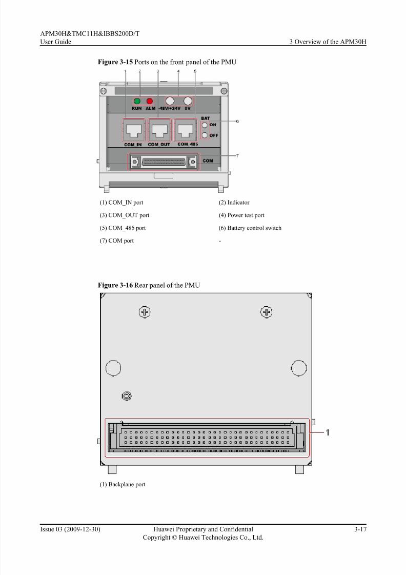
7/17/2019 Apm30 User Guide-(v200r303_03)
http://slidepdf.com/reader/full/apm30-user-guide-v200r30303 55/181
Figure 3-15 Ports on the front panel of the PMU
(1) COM_IN port (2) Indicator
(3) COM_OUT port (4) Power test port
(5) COM_485 port (6) Battery control switch
(7) COM port -
Figure 3-16 Rear panel of the PMU
(1) Backplane port
APM30H&TMC11H&IBBS200D/T
User Guide 3 Overview of the APM30H
Issue 03 (2009-12-30) Huawei Proprietary and Confidential
Copyright © Huawei Technologies Co., Ltd.
3-17

7/17/2019 Apm30 User Guide-(v200r303_03)
http://slidepdf.com/reader/full/apm30-user-guide-v200r30303 56/181
Table 3-7 lists the ports of the PMU.
Table 3-7 Ports of the PMU
Port Function
COM_IN port Communicating with the host or superior equipment
COM_OUT port Communicating with the subordinate equipment.
COM_485 port Communicating with the storage battery cabinet.
Battery control switch With two control ports: ON and OFF. They control connection to
or disconnection from batteries.
l To connect to batteries, press and hold the ON port for 5s to 10s.
l To disconnect from batteries, press and hold the OFF port for 5s
to 10s.
NOTE
l When operating the battery control switch, you need to insert a small
round bar into the hole. When you hear a crack, the batteries are connected
or disconnected.
COM port Connected to the external signal transfer board.
Backplane port Connected to the backplane.
Table 3-8 lists the indicators on the panel of the PMU.
Table 3-8 Indicators on the panel of the PMU
Label Color Status Description
RUN Green Blinking (on for 1s and
off for 1s)
The PMU is functional and is communicating
with the BBU properly.
Blinking (on for 0.125s
and off for 0.125s)
The PMU is functional, but its
communication with the BBU fails. If the
PMU does not communicate with the BBU
for one minute, the communication is
regarded as failed.
On or off The PMU is faulty (when it is not in the
power-on self-check state).
3 Overview of the APM30H
APM30H&TMC11H&IBBS200D/T
User Guide
3-18 Huawei Proprietary and Confidential
Copyright © Huawei Technologies Co., Ltd.
Issue 03 (2009-12-30)

7/17/2019 Apm30 User Guide-(v200r303_03)
http://slidepdf.com/reader/full/apm30-user-guide-v200r30303 57/181
Label Color Status Description
ALM Red On The base station reports at least one of the
following types of alarms:
l Mains failure alarm (including mains phase loss).
l Mains power overvoltage or undervoltage
l Busbar overvoltage or undervoltage
l Charging overcurrent
l Battery power-off alarm
l Battery group loop failure alarm
l Environmental temperature alarm
l Environmental humidity alarm
l PSU alarm
l Load power-off
Off No alarm is generated.
NOTE
Within 3s to 5s after the PMU is powered on, the ALM and RUN indicators are on at the same time for
about 3s.
DIP Switch
The DIP switch is positioned on the right panel of the PMU. The DIP switch has eight bits, which
are set to OFF before delivery. Figure 3-17 shows the DIP switch on the PMU.
Figure 3-17 DIP switch on the PMU
APM30H&TMC11H&IBBS200D/T
User Guide 3 Overview of the APM30H
Issue 03 (2009-12-30) Huawei Proprietary and Confidential
Copyright © Huawei Technologies Co., Ltd.
3-19

7/17/2019 Apm30 User Guide-(v200r303_03)
http://slidepdf.com/reader/full/apm30-user-guide-v200r30303 58/181
The DIP switch uses the binary method. The four least significant bits (1, 2, 3, and 4) of the DIP
switch define the secondary node address of the PMU. The four most significant bits (5, 6, 7,
and 8) are not defined and are reserved for future use.
You can set the monitoring address by setting the four least significant bits of the DIP switch.
The least significant bit corresponds to bit 0, and the fourth least significant bit corresponds to
bit 3.
NOTE
l The address monitored by the PMU is set to 3 by default. When two PMUs share the same bus, the
address monitored by the other PMU is set to 4.
l ON indicates the value 1, and OFF indicates the value 0.
PSU (AC/DC)
The Power Supply Unit (PSU) can convert 110 V AC or 220 V AC power into -48 V DC power.
Functions
The PSU (AC/DC) implements the following functions:
l Converts 110 V AC or 220 V AC into -48 V DC power
l Monitors the alarms related to module faults (such as output overvoltage, no output, and
fan faults), alarms related to module protection (such as overtemperature protection and
input overvoltage/undervoltage protection), and module out-of-position alarm
Panel
Figure 3-18 shows the panel of the PSU (AC/DC).
Figure 3-18 Panel of the PSU (AC/DC)
(1) Power LED
(2) Protection LED
(3) Fault LED
3 Overview of the APM30H
APM30H&TMC11H&IBBS200D/T
User Guide
3-20 Huawei Proprietary and Confidential
Copyright © Huawei Technologies Co., Ltd.
Issue 03 (2009-12-30)

7/17/2019 Apm30 User Guide-(v200r303_03)
http://slidepdf.com/reader/full/apm30-user-guide-v200r30303 59/181
LEDs
Table 3-9 describes the LEDs on the panel of the PSU (AC/DC).
Table 3-9 LEDs on the panel of the PSU (AC/DC)
Label Color Status Description
Power LED Green ON The PSU is normal.
OFF There are faults (such
as no AC input, or
overvoltage and
undervoltage of AC
input) related to the
mains, or the PSU
has no output.
Protection LED Yellow OFF The PSU is normal.
ON Temperature pre-
warning
Fault LED Red OFF The PSU is normal,
or the PSU has no
output because of the
faults (such as no AC
input, or overvoltage
and undervoltage of
AC input) related tothe mains.
ON The PSU has no
output because of
output overvoltage
shutdown, fan fault,
overtemperature
shutdown, remote
shutdown, or internal
problems of the PSU.
3.4.3 DC/DC Power System
The DC/DC power system converts +24 V DC power into -48 V DC power.
Components of the DC/DC Power System
The DC/DC power system consists of the PSUs (DC/DC) and power subrack (DC/DC).
Figure 3-19 shows the DC/DC power system.
APM30H&TMC11H&IBBS200D/T
User Guide 3 Overview of the APM30H
Issue 03 (2009-12-30) Huawei Proprietary and Confidential
Copyright © Huawei Technologies Co., Ltd.
3-21

7/17/2019 Apm30 User Guide-(v200r303_03)
http://slidepdf.com/reader/full/apm30-user-guide-v200r30303 60/181
Figure 3-19 DC/DC power system
TERMINALCONNECTION
DC
INPUT
DC
OUTPUT
+
+
LOAD-
LOAD-
RTN+
RTN+
-
-
ALM PRESENT
1 2
(1) PSUs (DC/DC) (2) Power subrack (DC/DC)
Table 3-10 describes the components of the DC/DC power system.
Table 3-10 Components of the DC/DC power system
Component Description
PSU (DC/DC) For details, see PSU (DC/DC).
Power subrack (DC/DC) For details, see Power Subrack (DC/DC).
PSU (DC/DC)
The PSU is the Power Supply Unit. The PSU (DC/DC) converts +24 V DC power into -48 VDC power.
Panel
Figure 3-20 shows the panel of the PSU (DC/DC).
3 Overview of the APM30H
APM30H&TMC11H&IBBS200D/T
User Guide
3-22 Huawei Proprietary and Confidential
Copyright © Huawei Technologies Co., Ltd.
Issue 03 (2009-12-30)

7/17/2019 Apm30 User Guide-(v200r303_03)
http://slidepdf.com/reader/full/apm30-user-guide-v200r30303 61/181
Figure 3-20 Panel of the PSU (DC/DC)
1 2 3
(1) Power LED (2) Protection LED (3) Fault LED
Functions
l Converting +24 V DC power into -48 V DC power and leading the -48 V DC power into
the DCDU-01.l Monitoring the unit and reporting alarms related to PSU faults (such as output overvoltage,
no output, and fan faults), alarms related to PSU protection (such as overtemperature
protection, and input overvoltage/undervoltage protection), and PSU out-of-position alarm,
if any.
LEDs
Table 3-11 describes the LEDs on the panel of the PSU (DC/DC).
Table 3-11 LEDs on the panel of the PSU (DC/DC)
LED Color Status Description
Power LED Green ON Normal.
OFF There is no power
input, or the fuse is
damaged.
Protection LED Yellow OFF Normal.
APM30H&TMC11H&IBBS200D/T
User Guide 3 Overview of the APM30H
Issue 03 (2009-12-30) Huawei Proprietary and Confidential
Copyright © Huawei Technologies Co., Ltd.
3-23
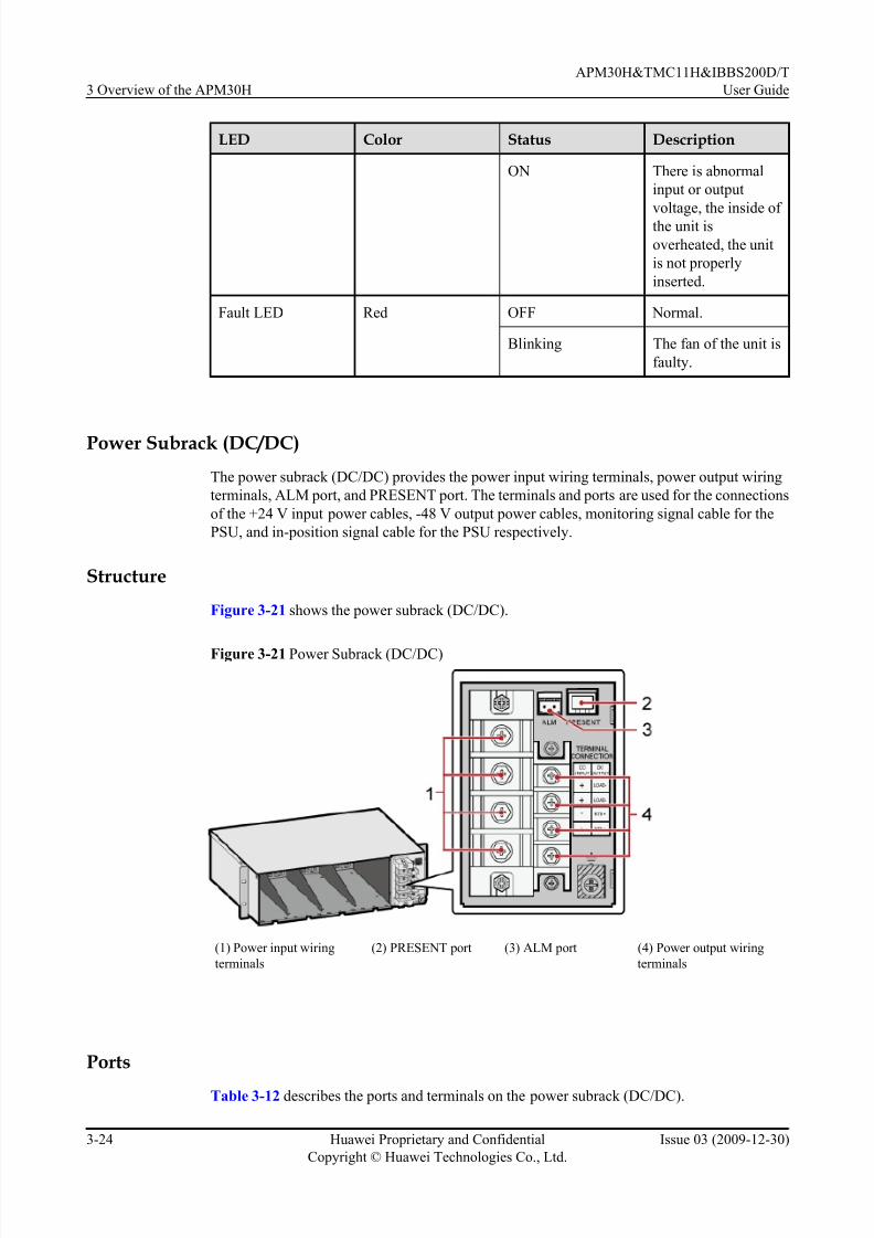
7/17/2019 Apm30 User Guide-(v200r303_03)
http://slidepdf.com/reader/full/apm30-user-guide-v200r30303 62/181
LED Color Status Description
ON There is abnormal
input or output
voltage, the inside of
the unit is
overheated, the unit
is not properly
inserted.
Fault LED Red OFF Normal.
Blinking The fan of the unit is
faulty.
Power Subrack (DC/DC)
The power subrack (DC/DC) provides the power input wiring terminals, power output wiring
terminals, ALM port, and PRESENT port. The terminals and ports are used for the connections
of the +24 V input power cables, -48 V output power cables, monitoring signal cable for the
PSU, and in-position signal cable for the PSU respectively.
Structure
Figure 3-21 shows the power subrack (DC/DC).
Figure 3-21 Power Subrack (DC/DC)
(1) Power input wiring
terminals
(2) PRESENT port (3) ALM port (4) Power output wiring
terminals
Ports
Table 3-12 describes the ports and terminals on the power subrack (DC/DC).
3 Overview of the APM30H
APM30H&TMC11H&IBBS200D/T
User Guide
3-24 Huawei Proprietary and Confidential
Copyright © Huawei Technologies Co., Ltd.
Issue 03 (2009-12-30)

7/17/2019 Apm30 User Guide-(v200r303_03)
http://slidepdf.com/reader/full/apm30-user-guide-v200r30303 63/181
Table 3-12 Ports and terminals on the power subrack (DC/DC)
Terminal/ Port
Label ConnectorType
Description
Power inputwiring terminal
DC INPUT OT terminal The + wiring terminals are used for theconnections of +24 V power cables, and
the - wiring terminals are used for the
connections of +24 V RTN cables.
Power output
wiring terminal
DC
OUTPUT
OT terminal The LOAD- wiring terminals are used
for the connections of the -48 V power
cables, and the RTN+ wiring terminals
are used for the connections of the -48 V
RTN cables.
Alarm signal
port
ALM Cord end
terminals
The ALM port is used for the connection
of the monitoring signal cable for the
PSU.
Present signal
port
PRESENT RJ-45 The PRESENT port is used for the
connection of the in-position signal
cable for the PSU.
3.4.4 Core of the Heat Exchanger
The core of the heat exchanger extends the area for the exchange of the air inside and outside
the APM30H cabinet, speeding up the air circulation and effectively decreasing the workingtemperature of the cabinet. In addition, the core of the heat exchanger keeps the dust away from
the cabinet.
Exterior
The core of the heat exchanger is positioned on the inner side of the front door of the APM30H
cabinet. Figure 3-22 shows the exterior of the core of the heat exchanger.
APM30H&TMC11H&IBBS200D/T
User Guide 3 Overview of the APM30H
Issue 03 (2009-12-30) Huawei Proprietary and Confidential
Copyright © Huawei Technologies Co., Ltd.
3-25
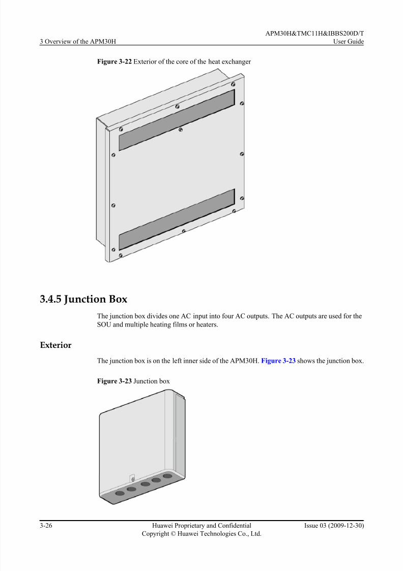
7/17/2019 Apm30 User Guide-(v200r303_03)
http://slidepdf.com/reader/full/apm30-user-guide-v200r30303 64/181
Figure 3-22 Exterior of the core of the heat exchanger
3.4.5 Junction BoxThe junction box divides one AC input into four AC outputs. The AC outputs are used for the
SOU and multiple heating films or heaters.
Exterior
The junction box is on the left inner side of the APM30H. Figure 3-23 shows the junction box.
Figure 3-23 Junction box
3 Overview of the APM30H
APM30H&TMC11H&IBBS200D/T
User Guide
3-26 Huawei Proprietary and Confidential
Copyright © Huawei Technologies Co., Ltd.
Issue 03 (2009-12-30)

7/17/2019 Apm30 User Guide-(v200r303_03)
http://slidepdf.com/reader/full/apm30-user-guide-v200r30303 65/181
Structure
Figure 3-24 shows the structure of the junction box.
Figure 3-24 Structure of the junction box
(1) L wiring terminals for four AC
outputs
(2) N wiring terminals for four AC
outputs
(3) PE wiring terminals for four AC
outputs
(4) Cable holes (5) N wiring terminals for the AC
input
(6) L wiring terminal for the AC
input
3.4.6 ELU
The Electronic Label Unit (ELU) automatically reports the information about the cabinet type,
facilitating fast troubleshooting.
The ELU is on the left inner side of the IBBS200D or IBBS200T or on the right inner side of
the APM30H, TMC11H, or RFC. Figure 3-25 shows the ELU.
APM30H&TMC11H&IBBS200D/T
User Guide 3 Overview of the APM30H
Issue 03 (2009-12-30) Huawei Proprietary and Confidential
Copyright © Huawei Technologies Co., Ltd.
3-27

7/17/2019 Apm30 User Guide-(v200r303_03)
http://slidepdf.com/reader/full/apm30-user-guide-v200r30303 66/181
Figure 3-25 ELU
(1) Housing (2) RJ-45 port
3.4.7 Door Status Sensor
The door status sensor monitors the opening and closing of the front door of the cabinet.
The door status sensor consists of the magnet part and switch part.
Figure 3-26 shows the magnet part of the door status sensor.
Figure 3-26 Magnet part of the door status sensor
Figure 3-27 shows the switch part of the door status sensor.
3 Overview of the APM30H
APM30H&TMC11H&IBBS200D/T
User Guide
3-28 Huawei Proprietary and Confidential
Copyright © Huawei Technologies Co., Ltd.
Issue 03 (2009-12-30)

7/17/2019 Apm30 User Guide-(v200r303_03)
http://slidepdf.com/reader/full/apm30-user-guide-v200r30303 67/181
Figure 3-27 Switch part of the door status sensor
3.4.8 Heater
The heater provides the proper operating temperature for the customer equipment working in
low temperature in the cabinet. The heater is optional.
Exterior
The heater is 1 U high. Figure 3-28 shows the heater.
Figure 3-28 Heater
Technical Specifications
The technical specifications of the heater are as follows:
l When the temperature in the cabinet is lower than 00C, the heater starts working; when the
temperature is higher than 150C, the heater stops working.
l The maximum heating power of the heater is 300 W.
3.4.9 SOU
The Service Outlet Unit (SOU) feeds AC power to the customer equipment. The SOU is optional.
Technical Specifications
Table 3-13 describes the technical specifications of the SOU.
APM30H&TMC11H&IBBS200D/T
User Guide 3 Overview of the APM30H
Issue 03 (2009-12-30) Huawei Proprietary and Confidential
Copyright © Huawei Technologies Co., Ltd.
3-29

7/17/2019 Apm30 User Guide-(v200r303_03)
http://slidepdf.com/reader/full/apm30-user-guide-v200r30303 68/181
Table 3-13 Technical specifications of the SOU
Item Specification
Dimensions (width x depth x height) 482.6 mm x 91 mm x 55 mm
Weight 1.5 kg
Input voltage range 200 V AC to 240 V AC
Maximum input current 10 A
Output voltage range 200 V AC to 240 V AC
Maximum output current 10 A
Operating frequency 50 Hz or 60 Hz
Operating temperature -400C to + 550C
Altitude ≤ 4,000 m
NOTEAbove the altitude of 3,000 m, the maximum
operating temperature decreases by 10C each time
the altitude increases by 100 m.
Protection class IP20
Exterior
Figure 3-29 shows the SOU.
Figure 3-29 SOU
(1) Power supply socket (2) MCB (3) Socket (Europe)
NOTE
The SOU can be used for different types of sockets in different countries. The types of sockets that are
supported are: North America, European standard, general-purpose, and UK types. Figure 3-30 shows the
different types of sockets.
3 Overview of the APM30H
APM30H&TMC11H&IBBS200D/T
User Guide
3-30 Huawei Proprietary and Confidential
Copyright © Huawei Technologies Co., Ltd.
Issue 03 (2009-12-30)

7/17/2019 Apm30 User Guide-(v200r303_03)
http://slidepdf.com/reader/full/apm30-user-guide-v200r30303 69/181
Figure 3-30 Different types of sockets
3.5 APM30H Cables
The APM30H cables consist of the PGND cable, input power cable, environment monitoring
signal cable, and monitoring signal cable for the PMU.
3.5.1 PGND Cable
The PGND cables consist of the PGND cable for the cabinet and PGND cables for the modules
in the cabinet.
3.5.2 Power Input Cables for the APM30H
The power in put cables for the APM30H lead external power to the power system. Different
configurations of the power system can support different types of power input, including the
220 V AC single-phase power input, 220 V AC three-phase power input, 110 V AC dual live
wire power in put, and +24 V DC power input.
3.5.3 Power Cable for the SOU
The input power cable feeds AC power into the SOU from the AC OUTPUT port of the EPS.
3.5.4 Power Cable for the Heater
The power ca ble for the heater feeds the AC input power into the heater from the junction box.
3.5.5 Power Cable for the Fan Box in the APM30H
The power ca ble feeds -48 V DC power into the fan box in the APM30H.
3.5.6 ELU Signal Cable
The ELU (Electronic Label Unit) signal cable transmits to the CMUA the information about the
cabinet type r eported by the ELU.
3.5.7 APM30H Door Status Monitoring Cable
The APM30H door status monitoring cable transmits the alarm signals to the PMU through theHPMI.
3.5.8 Transfer Cable for the Fan on the Front Door
The transfer cable feeds power into the fan on the front door of the APM30H or TMC11H and
transmits fan monitoring signals to the CMUA.
3.5.9 Environment Monitoring Signal Cable
The environment monitoring signal cable transmits external monitoring signals to the PMU.
3.5.10 Monitoring Signal Transfer Cable
The monitoring signal transfer cable transmits RS485 signals from the PMU to the CMUA.
APM30H&TMC11H&IBBS200D/T
User Guide 3 Overview of the APM30H
Issue 03 (2009-12-30) Huawei Proprietary and Confidential
Copyright © Huawei Technologies Co., Ltd.
3-31
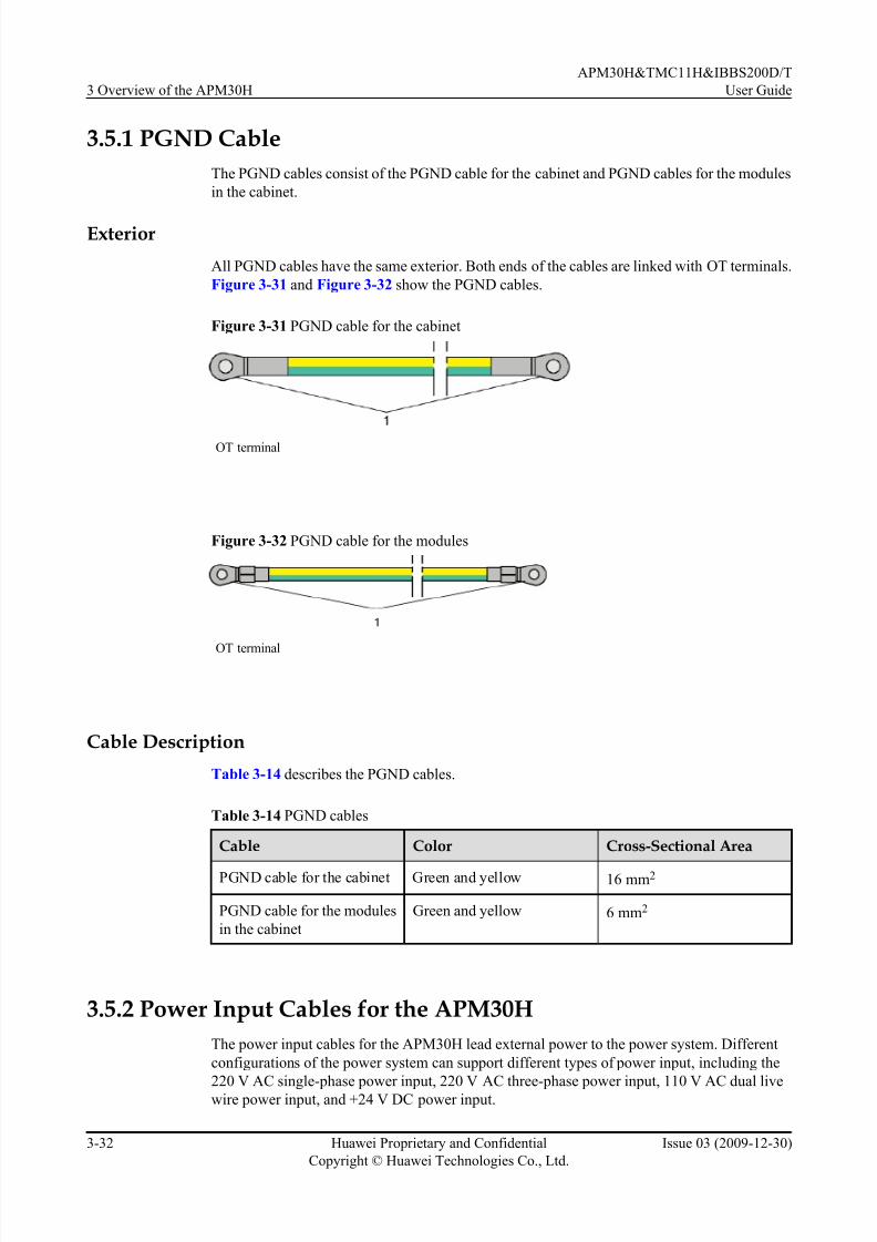
7/17/2019 Apm30 User Guide-(v200r303_03)
http://slidepdf.com/reader/full/apm30-user-guide-v200r30303 70/181
3.5.1 PGND Cable
The PGND cables consist of the PGND cable for the cabinet and PGND cables for the modules
in the cabinet.
Exterior
All PGND cables have the same exterior. Both ends of the cables are linked with OT terminals.
Figure 3-31 and Figure 3-32 show the PGND cables.
Figure 3-31 PGND cable for the cabinet
OT terminal
Figure 3-32 PGND cable for the modules
OT terminal
Cable Description
Table 3-14 describes the PGND cables.
Table 3-14 PGND cables
Cable Color Cross-Sectional Area
PGND cable for the cabinet Green and yellow 16 mm2
PGND cable for the modules
in the cabinet
Green and yellow 6 mm2
3.5.2 Power Input Cables for the APM30H
The power input cables for the APM30H lead external power to the power system. Different
configurations of the power system can sup port different types of power input, including the
220 V AC single-phase power input, 220 V AC three-phase power input, 110 V AC dual livewire power input, and +24 V DC power input.
3 Overview of the APM30H
APM30H&TMC11H&IBBS200D/T
User Guide
3-32 Huawei Proprietary and Confidential
Copyright © Huawei Technologies Co., Ltd.
Issue 03 (2009-12-30)

7/17/2019 Apm30 User Guide-(v200r303_03)
http://slidepdf.com/reader/full/apm30-user-guide-v200r30303 71/181
Exterior
Figure 3-33 shows the 220 V AC single-phase power input cable.
Figure 3-33 220 V AC single-phase power input cable
(1) OT terminal (6mm2, M6)
NOTE
The number of wires of an AC power input cable varies according to the cable type. Figure 3-33 shows
the 220 V AC single-phase power input cable.
Figure 3-34 shows the +24 V DC power input cable.
Figure 3-34 +24 V DC power cable
(1) OT terminal (25mm2, M6)
NOTE
A +24 V DC power input cable consists of two wires, one wire in red, and the other wire in black.
Specifications
Table 3-15 describes the specifications of different types of AC power input cables.
Table 3-15 Specifications of different types of AC power input cables
Cable Type Wire Type Wire Color Wire Diameter, OTAperture Type
220 V AC three-
phase power cable
L1 wire Yellow 2.5mm2, M6
L2 wire Green
L3 wire Red
N wire Blue
PE Yellow green
220 V AC single-
phase power cable
L wire Brown 6 mm2, M6
APM30H&TMC11H&IBBS200D/T
User Guide 3 Overview of the APM30H
Issue 03 (2009-12-30) Huawei Proprietary and Confidential
Copyright © Huawei Technologies Co., Ltd.
3-33

7/17/2019 Apm30 User Guide-(v200r303_03)
http://slidepdf.com/reader/full/apm30-user-guide-v200r30303 72/181
Cable Type Wire Type Wire Color Wire Diameter, OTAperture Type
N wire Blue
PE wire Yellow green
110 V AC dual live
wires
L1 wire Black 6 mm2, M6
L2 cable Red
N White
PE wire Green
NOTE
The colors and appearance of cables delivered by Huawei vary with countries and areas. If cables are
purchased at local markets, the cables must comply with the local rules and regulations.
3.5.3 Power Cable for the SOU
The input power cable feeds AC power into the SOU from the AC OUTPUT port of the EPS.
Structure
Figure 3-35 shows the power cable for the SOU.
Figure 3-35 Power cable for the SOU
(1) OT terminal (1.5mm2, M4) (2) C13 connector
Pin Assignment
Table 3-16 shows the pin assignment for the wires of the power cable for the SOU.
3 Overview of the APM30H
APM30H&TMC11H&IBBS200D/T
User Guide
3-34 Huawei Proprietary and Confidential
Copyright © Huawei Technologies Co., Ltd.
Issue 03 (2009-12-30)
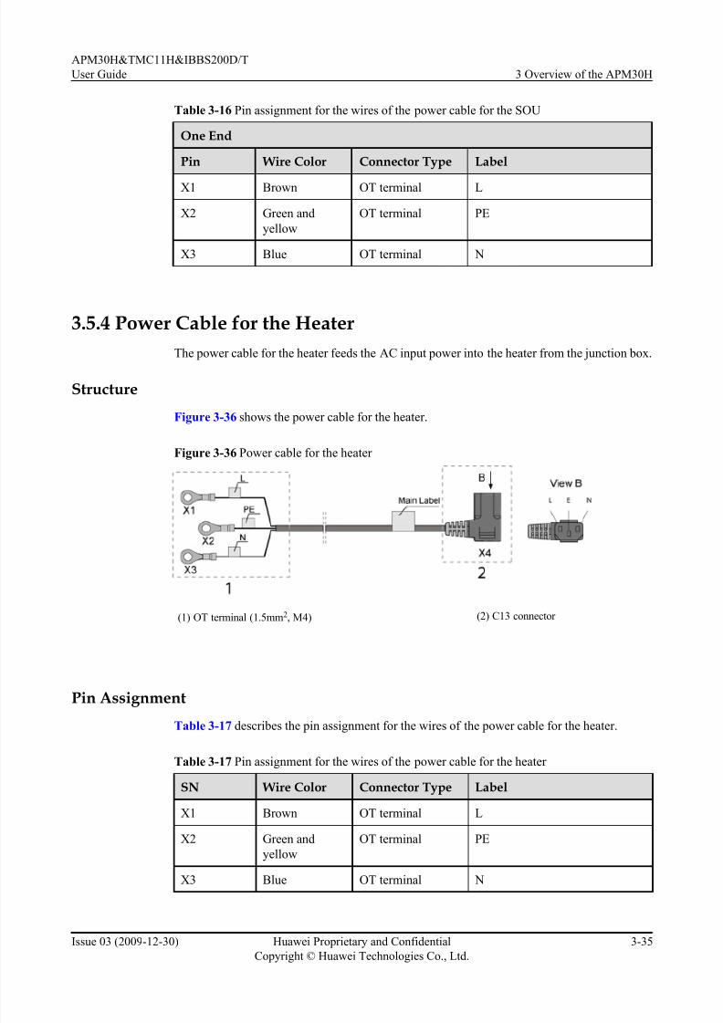
7/17/2019 Apm30 User Guide-(v200r303_03)
http://slidepdf.com/reader/full/apm30-user-guide-v200r30303 73/181
Table 3-16 Pin assignment for the wires of the power cable for the SOU
One End
Pin Wire Color Connector Type Label
X1 Brown OT terminal L
X2 Green and
yellow
OT terminal PE
X3 Blue OT terminal N
3.5.4 Power Cable for the Heater
The power cable for the heater feeds the AC input power into the heater from the junction box.
Structure
Figure 3-36 shows the power cable for the heater.
Figure 3-36 Power cable for the heater
(1) OT terminal (1.5mm2, M4) (2) C13 connector
Pin Assignment
Table 3-17 describes the pin assignment for the wires of the power cable for the heater.
Table 3-17 Pin assignment for the wires of the power cable for the heater
SN Wire Color Connector Type Label
X1 Brown OT terminal L
X2 Green and
yellow
OT terminal PE
X3 Blue OT terminal N
APM30H&TMC11H&IBBS200D/T
User Guide 3 Overview of the APM30H
Issue 03 (2009-12-30) Huawei Proprietary and Confidential
Copyright © Huawei Technologies Co., Ltd.
3-35

7/17/2019 Apm30 User Guide-(v200r303_03)
http://slidepdf.com/reader/full/apm30-user-guide-v200r30303 74/181
3.5.5 Power Cable for the Fan Box in the APM30H
The power cable feeds -48 V DC power into the fan box in the APM30H.
Structure
Figure 3-37 shows the power cable for the fan box in the APM30H.
Figure 3-37 Power cable for the fan box in the APM30H
(1) 3V3 power connector (2) Easy power receptacle (pressfit type) connector
3.5.6 ELU Signal Cable
The ELU (Electronic Label Unit) signal cable transmits to the CMUA the information about the
cabinet type reported by the ELU.
Structure
Figure 3-38 shows the ELU signal cable.
Figure 3-38 ELU signal cable
(1) RJ-45 connector
Pin Assignment
Table 3-18 describes the pin assignment for the wires of the ELU signal cable.
Table 3-18 Pin assignment for the wires of the ELU signal cable
X1 End X2 End Wire Color Type
X1.1 X2.1 White Twisted pair
X1.2 X2.2 Orange
3 Overview of the APM30H
APM30H&TMC11H&IBBS200D/T
User Guide
3-36 Huawei Proprietary and Confidential
Copyright © Huawei Technologies Co., Ltd.
Issue 03 (2009-12-30)

7/17/2019 Apm30 User Guide-(v200r303_03)
http://slidepdf.com/reader/full/apm30-user-guide-v200r30303 75/181
X1 End X2 End Wire Color Type
X1.3 X2.3 White Twisted pair
X1.6 X2.6 Green
X1.5 X2.5 White Twisted pair
X1.4 X2.4 Blue
X1.7 X2.7 White Twisted pair
X1.8 X2.8 Brown
3.5.7 APM30H Door Status Monitoring Cable
The APM30H door status monitoring cable transmits the alarm signals to the PMU through the
HPMI.
Structure
Figure 3-39 shows the APM30H door status monitoring cable.
Figure 3-39 APM30H door status monitoring cable
APM30H&TMC11H&IBBS200D/T
User Guide 3 Overview of the APM30H
Issue 03 (2009-12-30) Huawei Proprietary and Confidential
Copyright © Huawei Technologies Co., Ltd.
3-37

7/17/2019 Apm30 User Guide-(v200r303_03)
http://slidepdf.com/reader/full/apm30-user-guide-v200r30303 76/181
APM30H door status monitoring cable:
l The cable labeled 1 is terminated with a 2-pin socket at one end, which is connected to the
HPMI. The other end of the cable is terminated with a bare wire and a cord end terminal,
which are connected to the door status sensor and wiring terminal block respectively.
l The cable labeled 2 is terminated with a bare wire at one end, which is connected to thedoor status sensor. The other end of the cable is terminated with a cord end terminal, which
is connected to the wiring terminal block.
l The cable labeled 3 are terminated with cord end terminals at both ends, which are
connected to two ports at one side of the wiring terminal block.
3.5.8 Transfer Cable for the Fan on the Front Door
The transfer cable feeds power into the fan on the front door of the APM30H or TMC11H and
transmits fan monitoring signals to the CMUA.
Structure
Figure 3-40 shows the transfer cable for the fan on the front door.
Figure 3-40 transfer cable for the fan on the front door
Pin Assignment
Table 3-19 describes the pin assignment for the wires of the transfer cable for the fan on the
front door.
Table 3-19 Pin assignment for the wires of the transfer cable for the fan on the front door
Wire X1 End X2 End Color
W1 X1.1 X2.1 Black
W2 X1.2 X2.2 Black
W3 X1.3 X2.3 Black
W4 X1.4 X2.4 Black
3.5.9 Environment Monitoring Signal Cable
The environment monitoring signal cable transmits external monitoring signals to the PMU.
3 Overview of the APM30H
APM30H&TMC11H&IBBS200D/T
User Guide
3-38 Huawei Proprietary and Confidential
Copyright © Huawei Technologies Co., Ltd.
Issue 03 (2009-12-30)

7/17/2019 Apm30 User Guide-(v200r303_03)
http://slidepdf.com/reader/full/apm30-user-guide-v200r30303 77/181
Structure
The environment monitoring signal cable is black and 0.5 m long, with a DB50 male connector
at each end. Figure 3-41 shows the environment monitoring signal cable.
Figure 3-41 Environment monitoring signal cable
X1 X2
View A View B
A B1
W1
W2
(1) DB50 male connector
Pin Assignment
Table 3-20 describes the pin assignment for the wires of the environment monitoring signal
cable.
Table 3-20 Pin assignment for the wires of the environment monitoring signal cable
X1 End X2 End Description
1 1 Single wire
3 3 Twisted pair
4 4
5 5 Twisted pair
8 8
9 9 Twisted pair
10 10
11 11 Twisted pair
12 12
13 13 Twisted pair
14 14
16 16 Twisted pair
17 17
APM30H&TMC11H&IBBS200D/T
User Guide 3 Overview of the APM30H
Issue 03 (2009-12-30) Huawei Proprietary and Confidential
Copyright © Huawei Technologies Co., Ltd.
3-39
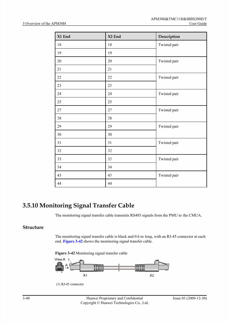
7/17/2019 Apm30 User Guide-(v200r303_03)
http://slidepdf.com/reader/full/apm30-user-guide-v200r30303 78/181
X1 End X2 End Description
18 18 Twisted pair
19 19
20 20 Twisted pair
21 21
22 22 Twisted pair
23 23
24 24 Twisted pair
25 25
27 27 Twisted pair
28 28
29 29 Twisted pair
30 30
31 31 Twisted pair
32 32
33 33 Twisted pair
34 34
43 43 Twisted pair
44 44
3.5.10 Monitoring Signal Transfer Cable
The monitoring signal transfer cable transmits RS485 signals from the PMU to the CMUA.
Structure
The monitoring signal transfer cable is black and 0.6 m long, with an RJ-45 connector at each
end. Figure 3-42 shows the monitoring signal transfer cable.
Figure 3-42 Monitoring signal transfer cable
(1) RJ-45 connector
3 Overview of the APM30H
APM30H&TMC11H&IBBS200D/T
User Guide
3-40 Huawei Proprietary and Confidential
Copyright © Huawei Technologies Co., Ltd.
Issue 03 (2009-12-30)

7/17/2019 Apm30 User Guide-(v200r303_03)
http://slidepdf.com/reader/full/apm30-user-guide-v200r30303 79/181
Pin Assignment
Table 3-21 describes the pin assignment for the wires of the monitoring signal transfer cable.
Table 3-21 Pin assignment for the wires of the monitoring signal transfer cableX1 End X2 End Description
X1.1 X2.1 Twisted pair
X1.2 X2.2
X1.3 X2.3 Twisted pair
X1.6 X2.6
X1.4 X2.4 Twisted pair
X1.5 X2.5
X1.7 X2.7 Twisted pair
X1.8 X2.8
APM30H&TMC11H&IBBS200D/T
User Guide 3 Overview of the APM30H
Issue 03 (2009-12-30) Huawei Proprietary and Confidential
Copyright © Huawei Technologies Co., Ltd.
3-41

7/17/2019 Apm30 User Guide-(v200r303_03)
http://slidepdf.com/reader/full/apm30-user-guide-v200r30303 80/181

7/17/2019 Apm30 User Guide-(v200r303_03)
http://slidepdf.com/reader/full/apm30-user-guide-v200r30303 81/181
4 Overview of the IBBS200T
About This Chapter
This describes the exterior, structure, components, and cables of the IBBS200T.
4.1 Exterior of the IBBS200T
The IBBS200T is brightly colored and elegantly designed. It is small in size and easy to transport.
4.2 Structure of the IBBS200T
The IBBS200T has a highly integrated and modular structure design. The power distribution
box (PDB) of the IBBS200T is installed to the upper right inside the cabinet, and the CMUA is
installed on the inner side of the cabinet door.
4.3 Cable Connections of the IBBS200T
The cables of the IBBS200T are power cables and signal cables.
4.4 IBBS200T Components
The components of the IBBS200T consist of the TEC cooler, power distribution box, CMUA,
and batteries.
4.5 IBBS200T Cables
The IBBS200T cables consist of the equipotential cable, input power cables for the batteries,
power cable f or the TEC cooler, and monitoring signal cable.
APM30H&TMC11H&IBBS200D/T
User Guide 4 Overview of the IBBS200T
Issue 03 (2009-12-30) Huawei Proprietary and Confidential
Copyright © Huawei Technologies Co., Ltd.
4-1

7/17/2019 Apm30 User Guide-(v200r303_03)
http://slidepdf.com/reader/full/apm30-user-guide-v200r30303 82/181
4.1 Exterior of the IBBS200T
The IBBS200T is brightly colored and elegantly designed. It is small in size and easy to transport.
Figure 4-1 shows exterior of the IBBS200T.
Figure 4-1 Exterior of the IBBS200T
4.2 Structure of the IBBS200T
The IBBS200T has a highly integrated and modular structure design. The power distribution
box (PDB) of the IBBS200T is installed to the upper right inside the cabinet, and the CMUA is
installed on the inner side of the cabinet door.
Figure 4-2 shows the internal structure of the IBBS200T.
4 Overview of the IBBS200T
APM30H&TMC11H&IBBS200D/T
User Guide
4-2 Huawei Proprietary and Confidential
Copyright © Huawei Technologies Co., Ltd.
Issue 03 (2009-12-30)

7/17/2019 Apm30 User Guide-(v200r303_03)
http://slidepdf.com/reader/full/apm30-user-guide-v200r30303 83/181
Figure 4-2 Internal structure of the IBBS200T
(1) TEC cooler (2) CMUA (3) TEC/Battery input
power wiring terminals
(4) MCBs of the TEC/
FAN
(5) MCB of the batteries in
the lower part
(6) MCB of the batteries in
the upper part
(7) TEC/Battery input
power wiring terminals
-
Structure of the cabinet:
l Each TEC/Batteries input power wiring terminal labeled 3 and 7 can provide two copper
busbars. Therefore, you can determine the installation position according to different
scenarios.
– 1. When the APM30H and the IBBS200T are stacked, the TEC/battery input power
cable is connected to the top of the power distribution box.
– 2. When the APM30H and the IBBS200T are chained, the TEC/battery input power
cable is connected to the bottom of the power distribution box.
l The CMUA on the inner side of the cabinet door of the IBBS200T collects alarm signals
from the door status sensor, FAN unit, and battery temperature sensor, and then reports the
signals to the PMU on the APM30H side to implement centralized monitoring.
4.3 Cable Connections of the IBBS200T
The cables of the IBBS200T are power cables and signal cables.
Figure 4-3 shows the cable connections of the IBBS200T.
APM30H&TMC11H&IBBS200D/T
User Guide 4 Overview of the IBBS200T
Issue 03 (2009-12-30) Huawei Proprietary and Confidential
Copyright © Huawei Technologies Co., Ltd.
4-3
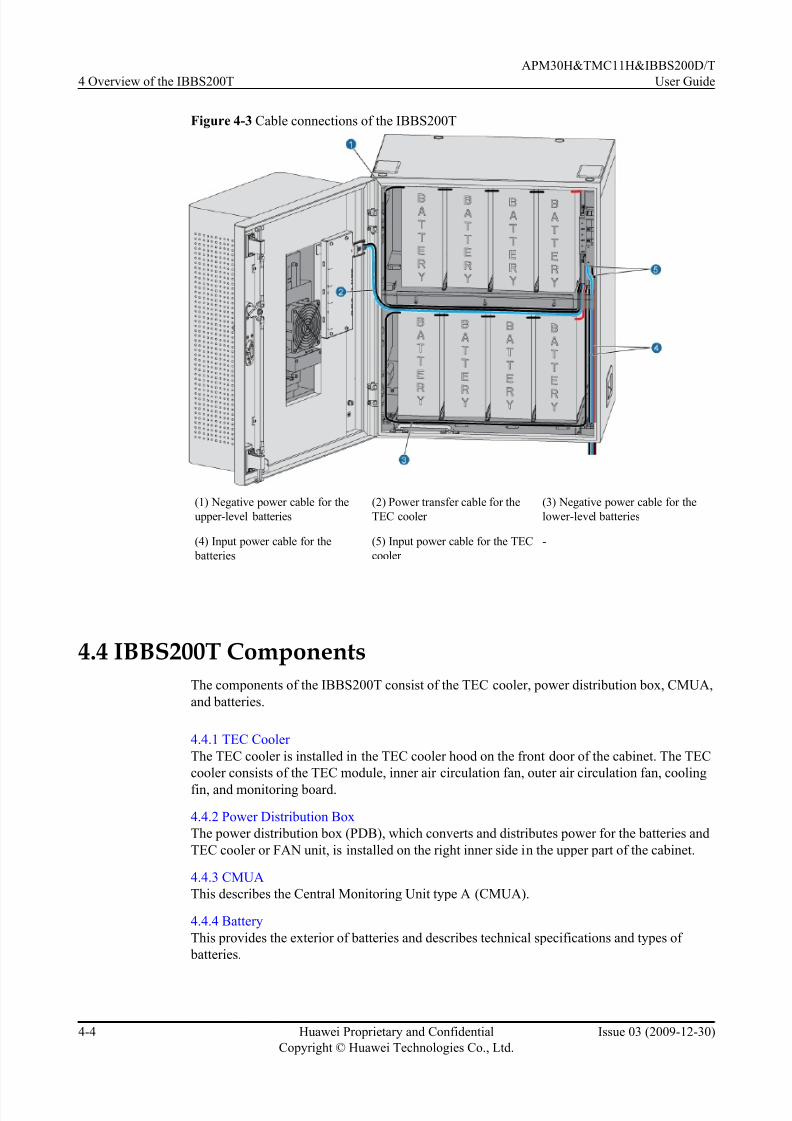
7/17/2019 Apm30 User Guide-(v200r303_03)
http://slidepdf.com/reader/full/apm30-user-guide-v200r30303 84/181
Figure 4-3 Cable connections of the IBBS200T
(1) Negative power cable for the
upper-level batteries
(2) Power transfer cable for the
TEC cooler
(3) Negative power cable for the
lower-level batteries
(4) Input power cable for the
batteries
(5) Input power cable for the TEC
cooler
-
4.4 IBBS200T Components
The components of the IBBS200T consist of the TEC cooler, power distribution box, CMUA,
and batteries.
4.4.1 TEC Cooler
The TEC cooler is installed in the TEC cooler hood on the front door of the cabinet. The TEC
cooler consists of the TEC module, inner air circulation fan, outer air circulation fan, cooling
fin, and monitoring board.
4.4.2 Power Distribution Box
The power distribution box (PDB), which converts and distributes power for the batteries and
TEC cooler or FAN unit, is installed on the right inner side in the upper part of the cabinet.
4.4.3 CMUA
This describes the Central Monitoring Unit type A (CMUA).
4.4.4 Battery
This provides the exterior of batteries and describes technical specifications and types of
batteries.
4 Overview of the IBBS200T
APM30H&TMC11H&IBBS200D/T
User Guide
4-4 Huawei Proprietary and Confidential
Copyright © Huawei Technologies Co., Ltd.
Issue 03 (2009-12-30)

7/17/2019 Apm30 User Guide-(v200r303_03)
http://slidepdf.com/reader/full/apm30-user-guide-v200r30303 85/181
4.4.1 TEC Cooler
The TEC cooler is installed in the TEC cooler hood on the front door of the cabinet. The TEC
cooler consists of the TEC module, inner air circulation fan, outer air circulation fan, cooling
fin, and monitoring board.
Exterior
Figure 4-4 shows the TEC cooler.
Figure 4-4 TEC cooler
Functions
The TEC cooler implements the following functions:
l The TEC cooler obtains -48 V DC power from the EPS of the APM30H.
l When the ambient temperature is 500C without solar radiation and the battery is in the float
charging state, the temperature in the cabinet is not greater than 400C. If the battery is in
the boost charging state, the temperature is not greater than 450C.
APM30H&TMC11H&IBBS200D/T
User Guide 4 Overview of the IBBS200T
Issue 03 (2009-12-30) Huawei Proprietary and Confidential
Copyright © Huawei Technologies Co., Ltd.
4-5

7/17/2019 Apm30 User Guide-(v200r303_03)
http://slidepdf.com/reader/full/apm30-user-guide-v200r30303 86/181
l When the ambient temperature is 500C with solar radiation of 1120 W/m2 and the battery
is in the float charging state, the temperature in the cabinet is not greater than 450C. If the
battery is in the boost charging state, the temperature is not greater than 500C.
l When the ambient temperature is 320C and there is no temperature difference between the
air inlets at the hot and cold sides of the TEC cooler, the refrigeration power of the TECcooler is not less than 190 W (±10%), and the COP is not less than 0.5.
4.4.2 Power Distribution Box
The power distribution box (PDB), which converts and distributes power for the batteries and
TEC cooler or FAN unit, is installed on the right inner side in the upper part of the cabinet.
Exterior
Figure 4-5 shows the PDB.
Figure 4-5 PDB
External Structure
Figure 4-6 shows the external structure of the PDB.
4 Overview of the IBBS200T
APM30H&TMC11H&IBBS200D/T
User Guide
4-6 Huawei Proprietary and Confidential
Copyright © Huawei Technologies Co., Ltd.
Issue 03 (2009-12-30)

7/17/2019 Apm30 User Guide-(v200r303_03)
http://slidepdf.com/reader/full/apm30-user-guide-v200r30303 87/181
Figure 4-6 External structure of the PDB
(1) RTN(+) cable for the batteries in
the upper part
(2) Input power cable for the
batteries
(3) Input power cable for the TEC
cooler or FAN unit
(4) Input power cable for the TEC
cooler or FAN unit
(5) Input power cable for the
batteries
(6) Power transfer cable for the TEC
cooler or FAN unit
(7) -48 V cable for the batteries in
the lower part
(8) -48 V cable for the batteries in
the upper part
(9) RTN(+) cable for the batteries in
the lower part
NOTE
The input power cables for the batteries and TEC cooler or FAN unit can be connected to the PDB from the top
or bottom in different scenarios. Figure 4-6 shows the cables connected to the PDB from the bottom.
4.4.3 CMUA
This describes the Central Monitoring Unit type A (CMUA).
Functions
The CMUA implements the following functions:
l Automatically adjusts and controls the temperature of the cabinet in different temperature
control modes.
l
Reserves three ports for Boolean inputs and detects the Boolean alarms in the cabinet. Theremote detection, however, is not supported.
APM30H&TMC11H&IBBS200D/T
User Guide 4 Overview of the IBBS200T
Issue 03 (2009-12-30) Huawei Proprietary and Confidential
Copyright © Huawei Technologies Co., Ltd.
4-7

7/17/2019 Apm30 User Guide-(v200r303_03)
http://slidepdf.com/reader/full/apm30-user-guide-v200r30303 88/181
l Provides an RJ-45 port for the ELU and monitors the information about the cabinet type.
Ports
Figure 4-7 shows the ports on the CMUA.
Figure 4-7 Ports on the CMUA
(1) TEM/TEM_BAT port (2) COM_OUT port (3) COM_IN port (4) LEDs
(5) ELU port (6) GATE port (7) IN0 port (8) IN1 port
(9) IN2 port (10) SMOKE port (11) FAN_EXT port (12) PWR port
(13) Port for the TEC cooler (14) FAN1/FAN_EXT port (15) FAN2/FAN_INTT port -
Table 4-1 describes the ports on the CMUA.
Table 4-1 Ports on the CMUA
Port Description
TEM/TEM_BAT port l The port is not used in the APM30H or
TMC11H.
l The silkscreen of the port in the RFC is
TEM. The port is used for connection to
the air inlet temperature sensor.
l The silkscreen of the port in the IBBS200D
or IBBS200T is TEM_BAT. The port isused for connection to the battery
temperature sensor.
COM_OUT port Used for connecting to the PMU or lower-
level CMUA
COM_IN port Used for connecting to the BBU or upper-
level CMUA
4 Overview of the IBBS200T
APM30H&TMC11H&IBBS200D/T
User Guide
4-8 Huawei Proprietary and Confidential
Copyright © Huawei Technologies Co., Ltd.
Issue 03 (2009-12-30)

7/17/2019 Apm30 User Guide-(v200r303_03)
http://slidepdf.com/reader/full/apm30-user-guide-v200r30303 89/181
Port Description
LEDs l RUN LED: indicates the running status of
fans.
l ALM LED: indicates the alarm status of the fans.
Table 4-2 describes the LEDs and their
status.
ELU port Used for reporting the information about the
cabinet type
GATE port Port for the door status sensor
IN0, IN1, and IN2 ports Used for receiving three Boolean inputs
SMOKE port Port for the smoke sensor
FAN_EXT port The port is used only in the APM30H or
TMC11H. It is used for connection to the
outer air circulation fans on the front door of
the cabinet.
PWR port Used for feeding DC input power into the
board
Port for the TEC cooler The port is used only in the IBBS200T. It is
used used for connection to the TEC cooler.
FAN1/FAN_EXT port l The silkscreen of the port in the APM30H
or TMC11H is FAN1. The port is used for connection to the fans in the fan box.
l The silkscreen of the port in the RFC or
IBBS200D is FAN1. The port is used for
connection to the fans on the right of the
fan box.
l The silkscreen of the port in the IBBS200T
is FAN_EXT. The port is used for
connection to the outer air circulation fans
of the TEC cooler.
FAN2/FAN_INT port l
The silkscreen of the port in the RFC or IBBS200D is FAN2. The port is used for
connection to the fans on the left of the fan
box.
l The silkscreen of the port in the IBBS200T
is FAN_INT. The port is used for
connection to the inner air cir culation fans
of the TEC cooler.
LEDs
Table 4-2 describes the LEDs on the CMUA.
APM30H&TMC11H&IBBS200D/T
User Guide 4 Overview of the IBBS200T
Issue 03 (2009-12-30) Huawei Proprietary and Confidential
Copyright © Huawei Technologies Co., Ltd.
4-9

7/17/2019 Apm30 User Guide-(v200r303_03)
http://slidepdf.com/reader/full/apm30-user-guide-v200r30303 90/181
Table 4-2 LEDs on the CMUA
Label Color Status Description
RUN Green Blinking (ON for 1s and
OFF for 1s)
The board is functional, and the
communication with the main control unit isnormal.
Blinking (ON for
0.125s and OFF for
0.125s)
The board is functional, but the
communication with the main control unit
fails. (If the board does not communicate with
the main control unit for one minute, the
communication fails.)
ON or OFF The board is faulty (it is not in the power-on
self check state).
ALM Red OFF No alarm is generated.
ON An alarm is generated, and the board needs to
be replaced.
Blinking (ON for 1s and
OFF for 1s)
An alarm is generated, and the alarm may be
caused by the faults of the related boards or
ports. Therefore, whether the board needs to
be replaced cannot be determined.
DIP Switches
Three DIP switches are displayed on the CMUA panel, indicating the working modes of the
CMUA in different cabinets. Figure 4-8 shows the DIP switches on the CMUA.
Figure 4-8 DIP switches on the CMUA
Figure 4-9 shows the bit settings of the CMUA in different cabinets.
4 Overview of the IBBS200T
APM30H&TMC11H&IBBS200D/T
User Guide
4-10 Huawei Proprietary and Confidential
Copyright © Huawei Technologies Co., Ltd.
Issue 03 (2009-12-30)

7/17/2019 Apm30 User Guide-(v200r303_03)
http://slidepdf.com/reader/full/apm30-user-guide-v200r30303 91/181
Figure 4-9 Bit settings of the CMUA in different cabinets
NOTE
The red rectangle in Figure 4-9 shows the position for connecting to the jumper cap.
4.4.4 Battery
This provides the exterior of batteries and describes technical specifications and types of
batteries.
NOTE
The exterior and technical specifications of the battery may vary according to manufacturer. The following
description is based on common batteries.
ExteriorFigure 4-10 shows the battery.
Figure 4-10 Battery
(1) A 12 V 50 Ah battery (2) A 12 V 92 Ah battery
Technical Specifications
Table 4-3 describes the technical specifications of the battery.
APM30H&TMC11H&IBBS200D/T
User Guide 4 Overview of the IBBS200T
Issue 03 (2009-12-30) Huawei Proprietary and Confidential
Copyright © Huawei Technologies Co., Ltd.
4-11

7/17/2019 Apm30 User Guide-(v200r303_03)
http://slidepdf.com/reader/full/apm30-user-guide-v200r30303 92/181
Table 4-3 Technical specifications of the battery
Type Dimensions (Width xHeight x Depth)
Weight
12 V 50 Ah 105 mm x 227 mm x 390 mm 21.5 kg
12 V 92 Ah 105 mm x 287 mm x 390 mm 33.5 kg
108 mm x 287 mm x 393 mm 35 kg
Configuration
The cabinet supports four types of battery packs: 48 V 50 Ah, 48 V 100 Ah, 48 V 92 Ah, and
48 V 184 Ah.
l The upper and lower 48 V 50 Ah battery packs can be connected in parallel to provide 48
V 100 Ah power.
l The upper and lower 48 V 92 Ah battery packs can be connected in parallel to provide 48
V 184 Ah power.
l Each battery pack contains four single batteries.
4.5 IBBS200T Cables
The IBBS200T cables consist of the equipotential cable, input power cables for the batteries,
power cable f or the TEC cooler, and monitoring signal cable.
4.5.1 PGND Cable
The PGND cables consist of the PGND cable for the cabinet and PGND cables for the modules
in the cabinet.
4.5.2 Equipotential Cable
The equipotential cable connects the PGND terminals of the cabinets, ensuring the equipotential
connection and safe running of the base station.
4.5.3 Power Cables for the Batteries
This describes the input power cables for the batteries, power cables between the batteries and
the copper bar in the junction box, and Inter-battery connection copper bar.
4.5.4 Power Cables for the TEC Cooler
The power cables for the TEC cooler consist of the input power cable for the TEC cooler and
the power transfer cable for the TEC cooler.
4.5.5 Monitoring Signal Cable for the Battery Cabinet
The monitoring signal cable collects and transmits the monitoring signals of the IBBS200D or
IBBS200T to the PMU.
4.5.1 PGND Cable
The PGND cables consist of the PGND cable for the cabinet and PGND cables for the modules
in the cabinet.
4 Overview of the IBBS200T
APM30H&TMC11H&IBBS200D/T
User Guide
4-12 Huawei Proprietary and Confidential
Copyright © Huawei Technologies Co., Ltd.
Issue 03 (2009-12-30)

7/17/2019 Apm30 User Guide-(v200r303_03)
http://slidepdf.com/reader/full/apm30-user-guide-v200r30303 93/181
Exterior
All PGND cables have the same exterior. Both ends of the cables are linked with OT terminals.
Figure 4-11 and Figure 4-12 show the PGND cables.
Figure 4-11 PGND cable for the cabinet
OT terminal
Figure 4-12 PGND cable for the modules
OT terminal
Cable Description
Table 4-4 describes the PGND cables.
Table 4-4 PGND cables
Cable Color Cross-Sectional Area
PGND cable for the cabinet Green and yellow 16 mm2
PGND cable for the modules
in the cabinet
Green and yellow 6 mm2
4.5.2 Equipotential Cable
The equipotential cable connects the PGND terminals of the cabinets, ensuring the equipotential
connection and safe running of the base station.
Exterior
Figure 4-13 shows the equipotential cable.
APM30H&TMC11H&IBBS200D/T
User Guide 4 Overview of the IBBS200T
Issue 03 (2009-12-30) Huawei Proprietary and Confidential
Copyright © Huawei Technologies Co., Ltd.
4-13

7/17/2019 Apm30 User Guide-(v200r303_03)
http://slidepdf.com/reader/full/apm30-user-guide-v200r30303 94/181
Figure 4-13 Equipotential cable
Cable Description
Table 4-5 describes the equipotential cable.
Table 4-5 Equipotential cable
Cable Color Cross-Sectional Area
Equipotential cable Green and yellow 16 mm2
4.5.3 Power Cables for the Batteries
This describes the input power cables for the batteries, power cables between the batteries and
the copper bar in the junction box, and Inter-battery connection copper bar.
Structure
Figure 4-14 shows the input power cables for the batteries.
Figure 4-14 Input power cables for the batteries
(1) Power series 120 connector (2) OT terminal (16mm2, M6)
Figure 4-15 shows the power cable between the batteries and the copper bar in the junction box.
4 Overview of the IBBS200T
APM30H&TMC11H&IBBS200D/T
User Guide
4-14 Huawei Proprietary and Confidential
Copyright © Huawei Technologies Co., Ltd.
Issue 03 (2009-12-30)

7/17/2019 Apm30 User Guide-(v200r303_03)
http://slidepdf.com/reader/full/apm30-user-guide-v200r30303 95/181
Figure 4-15 Power cable between the batteries and the copper bar in the junction box
(1) OT terminal (16mm2, M6)
The inter-battery connection copper bar between batteries is delivered with the batteries. Figure
4-16 shows the inter-battery connection copper bar.
Figure 4-16 Inter-battery connection copper bar
Specifications
l Of the input power cables for the batteries, the RTN(+) cable is red, with a cross-sectional
area of 16 mm2, and the NEG(-) cable is black, with a cross-sectional area of 16 mm2.
l Of the power cables between the batteries and the copper bar in the junction box, the RTN
(+) cable is red, with a cross-sectional area of 16 mm2
, and the NEG(-) cable is black, witha cross-sectional area of 16 mm2.
4.5.4 Power Cables for the TEC Cooler
The power cables for the TEC cooler consist of the input power cable for the TEC cooler and
the power transfer cable for the TEC cooler.
Structure
Figure 4-17 shows the input power cable for the TEC cooler.
Figure 4-17 Input power cable for the TEC cooler
(1) Easy power receptacle (pressfit type) connector (2) OT terminal (2.5mm2, M4)
APM30H&TMC11H&IBBS200D/T
User Guide 4 Overview of the IBBS200T
Issue 03 (2009-12-30) Huawei Proprietary and Confidential
Copyright © Huawei Technologies Co., Ltd.
4-15

7/17/2019 Apm30 User Guide-(v200r303_03)
http://slidepdf.com/reader/full/apm30-user-guide-v200r30303 96/181
Figure 4-18 shows the power transfer cable for the TEC cooler.
Figure 4-18 Power transfer cable for the TEC cooler
(1) 3V3 power connector (2) OT terminal (1.5mm2,
M6)
(3) OT terminal (6mm2,
M4)
(4) OT terminal (1.5mm2,
M4)
4.5.5 Monitoring Signal Cable for the Battery Cabinet
The monitoring signal cable collects and transmits the monitoring signals of the IBBS200D or
IBBS200T to the PMU.
Structure
Figure 4-19 shows the monitoring signal cable for the battery cabinet.
Figure 4-19 Monitoring signal cable for the battery cabinet
(1) RJ-45 connector
Pin Assignment
Table 4-6 describes the pin assignment for the wires of the monitoring signal cable for the battery
cabinet.
Table 4-6 Pin assignment for the wires of the monitoring signal cable for the battery cabinet
X1 End X2 End Wire Color Type
X1.1 X2.1 White Twisted pair
X1.2 X2.2 Orange
X1.3 X2.3 White Twisted pair
4 Overview of the IBBS200T
APM30H&TMC11H&IBBS200D/T
User Guide
4-16 Huawei Proprietary and Confidential
Copyright © Huawei Technologies Co., Ltd.
Issue 03 (2009-12-30)
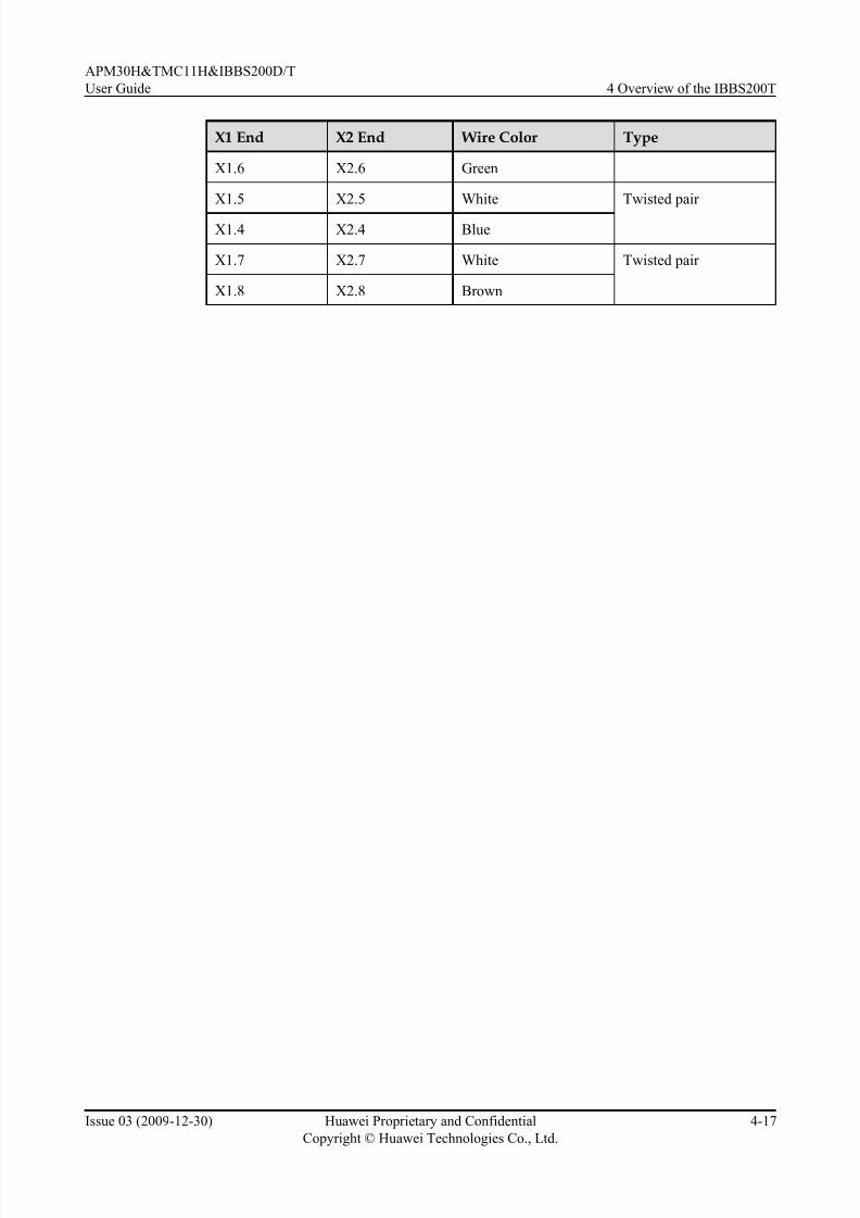
7/17/2019 Apm30 User Guide-(v200r303_03)
http://slidepdf.com/reader/full/apm30-user-guide-v200r30303 97/181
X1 End X2 End Wire Color Type
X1.6 X2.6 Green
X1.5 X2.5 White Twisted pair
X1.4 X2.4 Blue
X1.7 X2.7 White Twisted pair
X1.8 X2.8 Brown
APM30H&TMC11H&IBBS200D/T
User Guide 4 Overview of the IBBS200T
Issue 03 (2009-12-30) Huawei Proprietary and Confidential
Copyright © Huawei Technologies Co., Ltd.
4-17

7/17/2019 Apm30 User Guide-(v200r303_03)
http://slidepdf.com/reader/full/apm30-user-guide-v200r30303 98/181
7/17/2019 Apm30 User Guide-(v200r303_03)
http://slidepdf.com/reader/full/apm30-user-guide-v200r30303 99/181
5 Overview of the IBBS200D
About This Chapter
This describes the exterior, structure, components, and cables of the IBBS200D.
5.1 Exterior of the IBBS200D
The IBBS200D is brightly colored and elegantly designed. It is small in size and easy to transport.
5.2 Structure of the IBBS200D
The IBBS200D has a highly integrated and modular structure design. The power distribution
box (PDB) of the IBBS200T is installed to the upper right inside the cabinet, and the CMUA is
installed on the inner side of the cabinet door.
5.3 Cable Connections of the IBBS200D
The cables of the IBBS200D are power cables and signal cables.
5.4 IBBS200D Components
The components of the IBBS200D consist of the fans, fan box, CMUA, power distribution box,
batteries, and heating film. The heating film is optional.
5.5 IBBS200D Cables
The IBBS200D cables consist of the equipotential cable, input power cables for the batteries,
power cable f or the fans, input power cable for the heating film, and monitoring signal cable.
APM30H&TMC11H&IBBS200D/T
User Guide 5 Overview of the IBBS200D
Issue 03 (2009-12-30) Huawei Proprietary and Confidential
Copyright © Huawei Technologies Co., Ltd.
5-1

7/17/2019 Apm30 User Guide-(v200r303_03)
http://slidepdf.com/reader/full/apm30-user-guide-v200r30303 100/181
5.1 Exterior of the IBBS200D
The IBBS200D is brightly colored and elegantly designed. It is small in size and easy to transport.
Figure 5-1 shows exterior of the IBBS200D.
Figure 5-1 Exterior of the IBBS200D
5.2 Structure of the IBBS200D
The IBBS200D has a highly integrated and modular structure design. The power distribution
box (PDB) of the IBBS200T is installed to the upper right inside the cabinet, and the CMUA is
installed on the inner side of the cabinet door.
Figure 5-2 shows the internal structure of the IBBS200D
5 Overview of the IBBS200D
APM30H&TMC11H&IBBS200D/T
User Guide
5-2 Huawei Proprietary and Confidential
Copyright © Huawei Technologies Co., Ltd.
Issue 03 (2009-12-30)

7/17/2019 Apm30 User Guide-(v200r303_03)
http://slidepdf.com/reader/full/apm30-user-guide-v200r30303 101/181
Figure 5-2 Internal structure of the IBBS200D
(1) FAN unit (2) CMUA (3) ELU (4) Input power
transfer terminal for
the heating film
(5) FAN/Battery input
power wiring
terminals
(6) MCBs of the
TEC/FAN
(7) MCB of the
batteries in the lower part
(8) MCB of the
batteries in the upper part
(9) FAN/Battery input
power wiringterminals
-
Structure of the cabinet:
l Each FAN/battery input power wiring terminal numbered 5 and 9 can provide two copper
busbars. Therefore, you can determine the installation position according to different
scenarios.
– 1. When the APM30H and the IBBS200D are stacked, the FAN/Batteries input power
cable is connected to the top of the power distribution box.– 2. When the APM30H and the IBBS200D are chained, the FAN/battery input power
cable is connected to the bottom of the power distribution box.
l The CMUA on the inner side of the cabinet door of the IBBS200D collects alarm signals
from the door status sensor, FAN, and temperature sensor of the batteries, and then reports
them to the PMU on the APM30H side to achieve the central monitoring.
5.3 Cable Connections of the IBBS200D
The cables of the IBBS200D are power cables and signal cables.
Figure 5-3 shows the cable connections of the IBBS200D.
APM30H&TMC11H&IBBS200D/T
User Guide 5 Overview of the IBBS200D
Issue 03 (2009-12-30) Huawei Proprietary and Confidential
Copyright © Huawei Technologies Co., Ltd.
5-3

7/17/2019 Apm30 User Guide-(v200r303_03)
http://slidepdf.com/reader/full/apm30-user-guide-v200r30303 102/181
Figure 5-3 Cable connections of the IBBS200D
(1) 5.5.3 Power Cables for the
Batteries
(2) 5.5.4 Power Cables for the Fans
in the IBBS200D
(3) Power cable for the heating film
(4) 5.5.5 Power Cable for the
Heating Film
(5) 5.5.3 Power Cables for the
Batteries
(6) 5.5.3 Power Cables for the
Batteries
(7) 5.5.4 Power Cables for the Fans
in the IBBS200D
- -
5.4 IBBS200D Components
The components of the IBBS200D consist of the fans, fan box, CMUA, power distribution box,
batteries, and heating film. The heating film is optional.
5.4.1 Fan BoxThe fan box is installed on the front door of the cabinet and houses the fans and CMUA.
5.4.2 Power Distribution Box
The power distribution box (PDB), which converts and distributes power for the batteries and
TEC cooler or FAN unit, is installed on the right inner side in the upper part of the cabinet.
5.4.3 CMUA
This describes the Central Monitoring Unit type A (CMUA).
5.4.4 Battery
This provides the exterior of batteries and describes technical specifications and types of
batteries.
5.4.5 Heating Film
5 Overview of the IBBS200D
APM30H&TMC11H&IBBS200D/T
User Guide
5-4 Huawei Proprietary and Confidential
Copyright © Huawei Technologies Co., Ltd.
Issue 03 (2009-12-30)
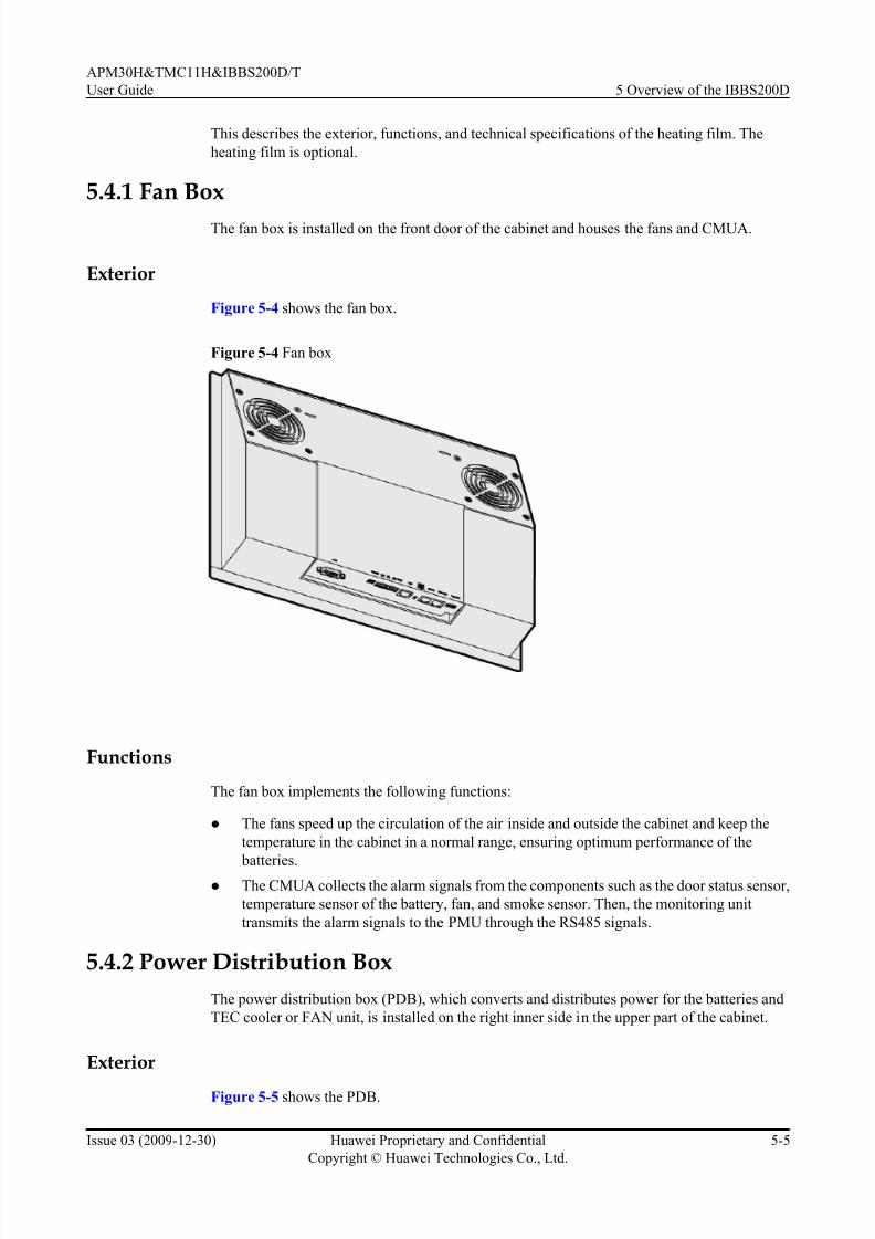
7/17/2019 Apm30 User Guide-(v200r303_03)
http://slidepdf.com/reader/full/apm30-user-guide-v200r30303 103/181
This describes the exterior, functions, and technical specifications of the heating film. The
heating film is optional.
5.4.1 Fan Box
The fan box is installed on the front door of the cabinet and houses the fans and CMUA.
Exterior
Figure 5-4 shows the fan box.
Figure 5-4 Fan box
Functions
The fan box implements the following functions:
l The fans speed up the circulation of the air inside and outside the cabinet and keep the
temperature in the cabinet in a normal range, ensuring optimum performance of the
batteries.
l The CMUA collects the alarm signals from the components such as the door status sensor,
temperature sensor of the battery, fan, and smoke sensor. Then, the monitoring unit
transmits the alarm signals to the PMU through the RS485 signals.
5.4.2 Power Distribution Box
The power distribution box (PDB), which converts and distributes power for the batteries and
TEC cooler or FAN unit, is installed on the right inner side in the upper part of the cabinet.
Exterior
Figure 5-5 shows the PDB.
APM30H&TMC11H&IBBS200D/T
User Guide 5 Overview of the IBBS200D
Issue 03 (2009-12-30) Huawei Proprietary and Confidential
Copyright © Huawei Technologies Co., Ltd.
5-5
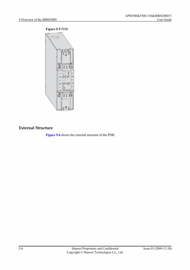
7/17/2019 Apm30 User Guide-(v200r303_03)
http://slidepdf.com/reader/full/apm30-user-guide-v200r30303 104/181
Figure 5-5 PDB
External Structure
Figure 5-6 shows the external structure of the PDB.
5 Overview of the IBBS200D
APM30H&TMC11H&IBBS200D/T
User Guide
5-6 Huawei Proprietary and Confidential
Copyright © Huawei Technologies Co., Ltd.
Issue 03 (2009-12-30)

7/17/2019 Apm30 User Guide-(v200r303_03)
http://slidepdf.com/reader/full/apm30-user-guide-v200r30303 105/181
Figure 5-6 External structure of the PDB
(1) RTN(+) cable for the batteries in
the upper part
(2) Input power cable for the
batteries
(3) Input power cable for the TEC
cooler or FAN unit
(4) Input power cable for the TEC
cooler or FAN unit
(5) Input power cable for the
batteries
(6) Power transfer cable for the TEC
cooler or FAN unit
(7) -48 V cable for the batteries in
the lower part
(8) -48 V cable for the batteries in
the upper part
(9) RTN(+) cable for the batteries in
the lower part
NOTE
The input power cables for the batteries and TEC cooler or FAN unit can be connected to the PDB from the top
or bottom in different scenarios. Figure 5-6 shows the cables connected to the PDB from the bottom.
5.4.3 CMUA
This describes the Central Monitoring Unit type A (CMUA).
Functions
The CMUA implements the following functions:
l Automatically adjusts and controls the temperature of the cabinet in different temperature
control modes.
l
Reserves three ports for Boolean inputs and detects the Boolean alarms in the cabinet. Theremote detection, however, is not supported.
APM30H&TMC11H&IBBS200D/T
User Guide 5 Overview of the IBBS200D
Issue 03 (2009-12-30) Huawei Proprietary and Confidential
Copyright © Huawei Technologies Co., Ltd.
5-7

7/17/2019 Apm30 User Guide-(v200r303_03)
http://slidepdf.com/reader/full/apm30-user-guide-v200r30303 106/181
l Provides an RJ-45 port for the ELU and monitors the information about the cabinet type.
Ports
Figure 5-7 shows the ports on the CMUA.
Figure 5-7 Ports on the CMUA
(1) TEM/TEM_BAT port (2) COM_OUT port (3) COM_IN port (4) LEDs
(5) ELU port (6) GATE port (7) IN0 port (8) IN1 port
(9) IN2 port (10) SMOKE port (11) FAN_EXT port (12) PWR port
(13) Port for the TEC cooler (14) FAN1/FAN_EXT port (15) FAN2/FAN_INTT port -
Table 5-1 describes the ports on the CMUA.
Table 5-1 Ports on the CMUA
Port Description
TEM/TEM_BAT port l The port is not used in the APM30H or
TMC11H.
l The silkscreen of the port in the RFC is
TEM. The port is used for connection to
the air inlet temperature sensor.
l The silkscreen of the port in the IBBS200D
or IBBS200T is TEM_BAT. The port isused for connection to the battery
temperature sensor.
COM_OUT port Used for connecting to the PMU or lower-
level CMUA
COM_IN port Used for connecting to the BBU or upper-
level CMUA
5 Overview of the IBBS200D
APM30H&TMC11H&IBBS200D/T
User Guide
5-8 Huawei Proprietary and Confidential
Copyright © Huawei Technologies Co., Ltd.
Issue 03 (2009-12-30)

7/17/2019 Apm30 User Guide-(v200r303_03)
http://slidepdf.com/reader/full/apm30-user-guide-v200r30303 107/181
Port Description
LEDs l RUN LED: indicates the running status of
fans.
l ALM LED: indicates the alarm status of the fans.
Table 5-2 describes the LEDs and their
status.
ELU port Used for reporting the information about the
cabinet type
GATE port Port for the door status sensor
IN0, IN1, and IN2 ports Used for receiving three Boolean inputs
SMOKE port Port for the smoke sensor
FAN_EXT port The port is used only in the APM30H or
TMC11H. It is used for connection to the
outer air circulation fans on the front door of
the cabinet.
PWR port Used for feeding DC input power into the
board
Port for the TEC cooler The port is used only in the IBBS200T. It is
used used for connection to the TEC cooler.
FAN1/FAN_EXT port l The silkscreen of the port in the APM30H
or TMC11H is FAN1. The port is used for connection to the fans in the fan box.
l The silkscreen of the port in the RFC or
IBBS200D is FAN1. The port is used for
connection to the fans on the right of the
fan box.
l The silkscreen of the port in the IBBS200T
is FAN_EXT. The port is used for
connection to the outer air circulation fans
of the TEC cooler.
FAN2/FAN_INT port l
The silkscreen of the port in the RFC or IBBS200D is FAN2. The port is used for
connection to the fans on the left of the fan
box.
l The silkscreen of the port in the IBBS200T
is FAN_INT. The port is used for
connection to the inner air cir culation fans
of the TEC cooler.
LEDs
Table 5-2 describes the LEDs on the CMUA.
APM30H&TMC11H&IBBS200D/T
User Guide 5 Overview of the IBBS200D
Issue 03 (2009-12-30) Huawei Proprietary and Confidential
Copyright © Huawei Technologies Co., Ltd.
5-9

7/17/2019 Apm30 User Guide-(v200r303_03)
http://slidepdf.com/reader/full/apm30-user-guide-v200r30303 108/181
Table 5-2 LEDs on the CMUA
Label Color Status Description
RUN Green Blinking (ON for 1s and
OFF for 1s)
The board is functional, and the
communication with the main control unit isnormal.
Blinking (ON for
0.125s and OFF for
0.125s)
The board is functional, but the
communication with the main control unit
fails. (If the board does not communicate with
the main control unit for one minute, the
communication fails.)
ON or OFF The board is faulty (it is not in the power-on
self check state).
ALM Red OFF No alarm is generated.
ON An alarm is generated, and the board needs to
be replaced.
Blinking (ON for 1s and
OFF for 1s)
An alarm is generated, and the alarm may be
caused by the faults of the related boards or
ports. Therefore, whether the board needs to
be replaced cannot be determined.
DIP Switches
Three DIP switches are displayed on the CMUA panel, indicating the working modes of the
CMUA in different cabinets. Figure 5-8 shows the DIP switches on the CMUA.
Figure 5-8 DIP switches on the CMUA
Figure 5-9 shows the bit settings of the CMUA in different cabinets.
5 Overview of the IBBS200D
APM30H&TMC11H&IBBS200D/T
User Guide
5-10 Huawei Proprietary and Confidential
Copyright © Huawei Technologies Co., Ltd.
Issue 03 (2009-12-30)

7/17/2019 Apm30 User Guide-(v200r303_03)
http://slidepdf.com/reader/full/apm30-user-guide-v200r30303 109/181
Figure 5-9 Bit settings of the CMUA in different cabinets
NOTE
The red rectangle in Figure 5-9 shows the position for connecting to the jumper cap.
5.4.4 Battery
This provides the exterior of batteries and describes technical specifications and types of
batteries.
NOTE
The exterior and technical specifications of the battery may vary according to manufacturer. The following
description is based on common batteries.
ExteriorFigure 5-10 shows the battery.
Figure 5-10 Battery
(1) A 12 V 50 Ah battery (2) A 12 V 92 Ah battery
Technical Specifications
Table 5-3 describes the technical specifications of the battery.
APM30H&TMC11H&IBBS200D/T
User Guide 5 Overview of the IBBS200D
Issue 03 (2009-12-30) Huawei Proprietary and Confidential
Copyright © Huawei Technologies Co., Ltd.
5-11

7/17/2019 Apm30 User Guide-(v200r303_03)
http://slidepdf.com/reader/full/apm30-user-guide-v200r30303 110/181
Table 5-3 Technical specifications of the battery
Type Dimensions (Width xHeight x Depth)
Weight
12 V 50 Ah 105 mm x 227 mm x 390 mm 21.5 kg
12 V 92 Ah 105 mm x 287 mm x 390 mm 33.5 kg
108 mm x 287 mm x 393 mm 35 kg
Configuration
The cabinet supports four types of battery packs: 48 V 50 Ah, 48 V 100 Ah, 48 V 92 Ah, and
48 V 184 Ah.
l The upper and lower 48 V 50 Ah battery packs can be connected in parallel to provide 48
V 100 Ah power.
l The upper and lower 48 V 92 Ah battery packs can be connected in parallel to provide 48
V 184 Ah power.
l Each battery pack contains four single batteries.
5.4.5 Heating Film
This describes the exterior, functions, and technical specifications of the heating film. The
heating film is optional.
NOTE
The IBBS200D has two heating films, which are installed on the upper and lower baffle plates.
Exterior
Figure 5-11 shows the heating film.
Figure 5-11 Heating film
5 Overview of the IBBS200D
APM30H&TMC11H&IBBS200D/T
User Guide
5-12 Huawei Proprietary and Confidential
Copyright © Huawei Technologies Co., Ltd.
Issue 03 (2009-12-30)

7/17/2019 Apm30 User Guide-(v200r303_03)
http://slidepdf.com/reader/full/apm30-user-guide-v200r30303 111/181
Functions
The heating film ensures that the batteries are stored and function at the proper temperature whenthe ambient temperature is low. When the ambient temperature is lower than the normal working
temperature of the battery, the battery capacity decreases. In this case, the heating film is required
to guarantee the best performance of the batteries.
Technical Specifications
The technical specifications of the heating film are as follows:
l The heating film works with the rated voltage of 220 V AC, and the rated heating power
is 100 W.
l
When the ambient temperature is lower than 0
0
C, the heating film starts working; when theambient temperature is higher than 150C, the heating film stops working.
l The surf ace of the heating film can tolerate a temperature from -400C to +2500C.
5.5 IBBS200D Cables
The IBBS200D cables consist of the equipotential cable, input power cables for the batteries,
power cable f or the fans, input power cable for the heating film, and monitoring signal cable.
5.5.1 PGND Cable
The PGND cables consist of the PGND cable for the cabinet and PGND cables for the modulesin the cabinet.
5.5.2 Equipotential Cable
The equipotential cable connects the PGND terminals of the cabinets, ensuring the equipotential
connection and safe running of the base station.
5.5.3 Power Cables for the Batteries
This describes the input power cables for the batteries, power cables between the batteries and
the copper bar in the junction box, and Inter-battery connection copper bar.
5.5.4 Power Cables for the Fans in the IBBS200D
The power cables for the fans in the IBBS200D consist of the input power cable for the fans in
the IBBS200D and the power transfer cable for the fans in the IBBS200D.
5.5.5 Power Cable for the Heating Film
The power cable connects the output terminal on the junction box on the left of the AMP30H
cabinet to the AC power input terminal on the heating film.
5.5.6 Monitoring Signal Cable for the Battery Cabinet
The monitoring signal cable collects and transmits the monitoring signals of the IBBS200D or
IBBS200T to the PMU.
5.5.1 PGND Cable
The PGND cables consist of the PGND cable for the cabinet and PGND cables for the modulesin the cabinet.
APM30H&TMC11H&IBBS200D/T
User Guide 5 Overview of the IBBS200D
Issue 03 (2009-12-30) Huawei Proprietary and Confidential
Copyright © Huawei Technologies Co., Ltd.
5-13

7/17/2019 Apm30 User Guide-(v200r303_03)
http://slidepdf.com/reader/full/apm30-user-guide-v200r30303 112/181
Exterior
All PGND cables have the same exterior. Both ends of the cables are linked with OT terminals.
Figure 5-12 and Figure 5-13 show the PGND cables.
Figure 5-12 PGND cable for the cabinet
OT terminal
Figure 5-13 PGND cable for the modules
OT terminal
Cable Description
Table 5-4 describes the PGND cables.
Table 5-4 PGND cables
Cable Color Cross-Sectional Area
PGND cable for the cabinet Green and yellow 16 mm2
PGND cable for the modules
in the cabinet
Green and yellow 6 mm2
5.5.2 Equipotential Cable
The equipotential cable connects the PGND terminals of the cabinets, ensuring the equipotential
connection and safe running of the base station.
Exterior
Figure 5-14 shows the equipotential cable.
5 Overview of the IBBS200D
APM30H&TMC11H&IBBS200D/T
User Guide
5-14 Huawei Proprietary and Confidential
Copyright © Huawei Technologies Co., Ltd.
Issue 03 (2009-12-30)

7/17/2019 Apm30 User Guide-(v200r303_03)
http://slidepdf.com/reader/full/apm30-user-guide-v200r30303 113/181
Figure 5-14 Equipotential cable
Cable Description
Table 5-5 describes the equipotential cable.
Table 5-5 Equipotential cable
Cable Color Cross-Sectional Area
Equipotential cable Green and yellow 16 mm2
5.5.3 Power Cables for the Batteries
This describes the input power cables for the batteries, power cables between the batteries and
the copper bar in the junction box, and Inter-battery connection copper bar.
Structure
Figure 5-15 shows the input power cables for the batteries.
Figure 5-15 Input power cables for the batteries
(1) Power series 120 connector (2) OT terminal (16mm2, M6)
Figure 5-16 shows the power cable between the batteries and the copper bar in the junction box.
APM30H&TMC11H&IBBS200D/T
User Guide 5 Overview of the IBBS200D
Issue 03 (2009-12-30) Huawei Proprietary and Confidential
Copyright © Huawei Technologies Co., Ltd.
5-15

7/17/2019 Apm30 User Guide-(v200r303_03)
http://slidepdf.com/reader/full/apm30-user-guide-v200r30303 114/181
Figure 5-16 Power cable between the batteries and the copper bar in the junction box
(1) OT terminal (16mm2, M6)
The inter-battery connection copper bar between batteries is delivered with the batteries. Figure
5-17 shows the inter-battery connection copper bar.
Figure 5-17 Inter-battery connection copper bar
Specifications
l Of the input power cables for the batteries, the RTN(+) cable is red, with a cross-sectional
area of 16 mm2, and the NEG(-) cable is black, with a cross-sectional area of 16 mm2.
l Of the power cables between the batteries and the copper bar in the junction box, the RTN
(+) cable is red, with a cross-sectional area of 16 mm2
, and the NEG(-) cable is black, witha cross-sectional area of 16 mm2.
5.5.4 Power Cables for the Fans in the IBBS200D
The power cables for the fans in the IBBS200D consist of the input power cable for the fans in
the IBBS200D and the power transfer cable for the fans in the IBBS200D.
Structure
Figure 5-18 shows the input power cable for the fans in the IBBS200D.
Figure 5-18 Input power cable for the fans in the IBBS200D
(1) Easy power receptacle (pressfit type) connector (2) OT terminal (2.5mm2, M4)
5 Overview of the IBBS200D
APM30H&TMC11H&IBBS200D/T
User Guide
5-16 Huawei Proprietary and Confidential
Copyright © Huawei Technologies Co., Ltd.
Issue 03 (2009-12-30)

7/17/2019 Apm30 User Guide-(v200r303_03)
http://slidepdf.com/reader/full/apm30-user-guide-v200r30303 115/181
Figure 5-19 shows the power transfer cable for the fans in the IBBS200D.
Figure 5-19 Power transfer cable for the fans in the IBBS200D
(1) 3V3 power connector (2) OT terminal (1.5mm2,
M6)
(3) OT terminal (6mm2,
M4)
(4) OT terminal (1.5mm2,
M4)
5.5.5 Power Cable for the Heating Film
The power cable connects the output terminal on the junction box on the left of the AMP30H
cabinet to the AC power input terminal on the heating film.
Structure
Figure 5-20 shows the power cable for the heating film.
Figure 5-20 Power cable for the heating film
(1) OT terminal (1.5mm2, M4) for the APM30H cabinet (2) OT terminal (1.5mm2, M4) for the battery cabinet
SpecificationsThe AC power cable for the heating film has a cross-sectional area of 1.5 mm2 with a black
jacket. The cable consists of the blue and brown wires.
5.5.6 Monitoring Signal Cable for the Battery Cabinet
The monitoring signal cable collects and transmits the monitoring signals of the IBBS200D or
IBBS200T to the PMU.
Structure
Figure 5-21 shows the monitoring signal cable for the battery cabinet.
APM30H&TMC11H&IBBS200D/T
User Guide 5 Overview of the IBBS200D
Issue 03 (2009-12-30) Huawei Proprietary and Confidential
Copyright © Huawei Technologies Co., Ltd.
5-17

7/17/2019 Apm30 User Guide-(v200r303_03)
http://slidepdf.com/reader/full/apm30-user-guide-v200r30303 116/181
Figure 5-21 Monitoring signal cable for the battery cabinet
(1) RJ-45 connector
Pin Assignment
Table 5-6 describes the pin assignment for the wires of the monitoring signal cable for the battery
cabinet.
Table 5-6 Pin assignment for the wires of the monitoring signal cable for the battery cabinet
X1 End X2 End Wire Color Type
X1.1 X2.1 White Twisted pair
X1.2 X2.2 Orange
X1.3 X2.3 White Twisted pair
X1.6 X2.6 Green
X1.5 X2.5 White Twisted pair
X1.4 X2.4 Blue
X1.7 X2.7 White Twisted pair
X1.8 X2.8 Brown
5 Overview of the IBBS200D
APM30H&TMC11H&IBBS200D/T
User Guide
5-18 Huawei Proprietary and Confidential
Copyright © Huawei Technologies Co., Ltd.
Issue 03 (2009-12-30)

7/17/2019 Apm30 User Guide-(v200r303_03)
http://slidepdf.com/reader/full/apm30-user-guide-v200r30303 117/181
6 Overview of the TMC11H
About This Chapter
This describes the exterior, structure, components, and cables of the TMC11H.
6.1 Exterior of the TMC11H
The TMC11H is brightly colored and elegantly designed. It is small in size and easy to transport.
6.2 Structure of the TMC11H
The TMC11H has a highly integrated and modular structure design. Thus, the cabinet is easy to
operate and maintain.
6.3 Cable Connections of the TMC11HThe cables of the TMC11H are power cables and signal cables.
6.4 TMC11H Components
The components of the TMC11H consist of the fan box, DCDU-03, and heater. The heater is
optional.
6.5 TMC11H Cables
The TMC11H cables consist of the equipotential cable, input power cable, power cable for the
fan box, ELU signal cable, signal cables between the CMUA and the door status sensor, and
transfer cable for the fan on the front door .
APM30H&TMC11H&IBBS200D/T
User Guide 6 Overview of the TMC11H
Issue 03 (2009-12-30) Huawei Proprietary and Confidential
Copyright © Huawei Technologies Co., Ltd.
6-1

7/17/2019 Apm30 User Guide-(v200r303_03)
http://slidepdf.com/reader/full/apm30-user-guide-v200r30303 118/181
6.1 Exterior of the TMC11H
The TMC11H is brightly colored and elegantly designed. It is small in size and easy to transport.
Figure 6-1 shows the TMC11H.
Figure 6-1 TMC11H
6.2 Structure of the TMC11H
The TMC11H has a highly integrated and modular structure design. Thus, the cabinet is easy tooperate and maintain.
Figure 6-2 shows the internal structure of the TMC11H.
6 Overview of the TMC11H
APM30H&TMC11H&IBBS200D/T
User Guide
6-2 Huawei Proprietary and Confidential
Copyright © Huawei Technologies Co., Ltd.
Issue 03 (2009-12-30)

7/17/2019 Apm30 User Guide-(v200r303_03)
http://slidepdf.com/reader/full/apm30-user-guide-v200r30303 119/181
Figure 6-2 Internal structure of the TMC11H
(1) Inner air circulation fan (2) CMUA (3) DCDU-03
(4) ELU (5) Door status sensor (6) Outer air circulation fan
(7) Heat exchanger (8) Junction box -
The TMC11H has the following features with regard to its structure:
l If the heater is not installed, the TMC11H provides a 11 U space for user equipment.
l The heater should be installed in the 1 U space at the bottom of the TMC11H.
l The TMC11H provides a 1 U space at the top for operation and maintenance of the fan box.
6.3 Cable Connections of the TMC11HThe cables of the TMC11H are power cables and signal cables.
Figure 6-3 shows the cable connection of the TMC11H.
APM30H&TMC11H&IBBS200D/T
User Guide 6 Overview of the TMC11H
Issue 03 (2009-12-30) Huawei Proprietary and Confidential
Copyright © Huawei Technologies Co., Ltd.
6-3

7/17/2019 Apm30 User Guide-(v200r303_03)
http://slidepdf.com/reader/full/apm30-user-guide-v200r30303 120/181
Figure 6-3 Cable connections of the TMC11H
(1) Power transfer cable for the
heater
(2) 6.5.2 Input Power Cable for the
TMC11H
(3) 6.5.5 Door Status Monitoring
Cable
(4) 6.5.4 ELU Signal Cable (5) 6.5.3 Power Cable for the Fan
Box in the TMC11H
-
6.4 TMC11H Components
The components of the TMC11H consist of the fan box, DCDU-03, and heater . The heater is
optional.
6.4.1 Fan Box
The fan box consists of the fan subrack, fans, HPMI, and CMUA.
6.4.2 DCDU-03
The Direct Current Distribution Unit-03 (DCDU-03) supplies DC power to each component in
the cabinet. The height of the DCDU-03 is 1 U. It can be classified into the DCDU-03B and
DCDU-03C according to the configured MCBs and application scenarios. The two models have
the same exterior, engineering specifications, and ports.
6.4.3 Heater
The heater provides the proper operating temperature for the customer equipment working in
low temperature in the cabinet. The heater is optional.
6.4.1 Fan Box
The fan box consists of the fan subrack, fans, HPMI, and CMUA.
6 Overview of the TMC11H
APM30H&TMC11H&IBBS200D/T
User Guide
6-4 Huawei Proprietary and Confidential
Copyright © Huawei Technologies Co., Ltd.
Issue 03 (2009-12-30)

7/17/2019 Apm30 User Guide-(v200r303_03)
http://slidepdf.com/reader/full/apm30-user-guide-v200r30303 121/181
Figure 6-4 shows the fan box.
Figure 6-4 Fan Box
(1) Fans (2) Fan subrack (3) CMUA (4) HPMI
Fans
Fans are installed in the fan box of the cabinet. They dissipate the heat for the cabinet.
Exterior
Figure 6-5 shows a fan.
Figure 6-5 Fan
Technical Specifications
Table 6-1 describes the technical specifications of the fan.
Table 6-1 Technical specifications of the fan
Item Specification
Dimensions (Diameter x Height) 175 mm x 69 mm
APM30H&TMC11H&IBBS200D/T
User Guide 6 Overview of the TMC11H
Issue 03 (2009-12-30) Huawei Proprietary and Confidential
Copyright © Huawei Technologies Co., Ltd.
6-5
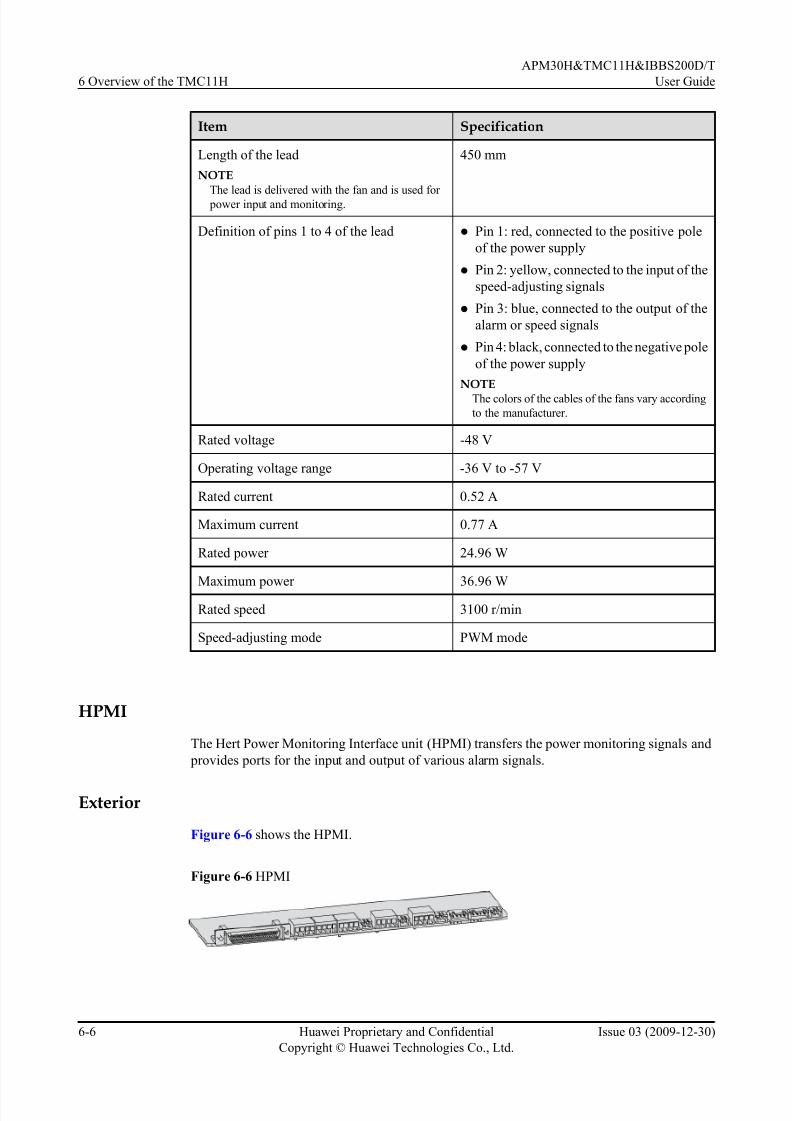
7/17/2019 Apm30 User Guide-(v200r303_03)
http://slidepdf.com/reader/full/apm30-user-guide-v200r30303 122/181
Item Specification
Length of the lead
NOTEThe lead is delivered with the fan and is used for
power input and monitoring.
450 mm
Definition of pins 1 to 4 of the lead l Pin 1: red, connected to the positive pole
of the power supply
l Pin 2: yellow, connected to the input of the
speed-adjusting signals
l Pin 3: blue, connected to the output of the
alarm or speed signals
l Pin 4: black, connected to the negative pole
of the power supply
NOTEThe colors of the cables of the fans vary according
to the manufacturer.
Rated voltage -48 V
Operating voltage range -36 V to -57 V
Rated current 0.52 A
Maximum current 0.77 A
Rated power 24.96 W
Maximum power 36.96 W
Rated speed 3100 r/min
Speed-adjusting mode PWM mode
HPMI
The Hert Power Monitoring Interface unit (HPMI) transfers the power monitoring signals and
provides ports for the input and output of various alarm signals.
Exterior
Figure 6-6 shows the HPMI.
Figure 6-6 HPMI
6 Overview of the TMC11H
APM30H&TMC11H&IBBS200D/T
User Guide
6-6 Huawei Proprietary and Confidential
Copyright © Huawei Technologies Co., Ltd.
Issue 03 (2009-12-30)

7/17/2019 Apm30 User Guide-(v200r303_03)
http://slidepdf.com/reader/full/apm30-user-guide-v200r30303 123/181
Ports
Figure 6-7 shows the ports on the panel of the HPMI, and Table 6-2 describes the ports on the
panel of the HPMI.
Figure 6-7 Ports on the panel of the HPMI
PMU_DB50 GATE TEM_BAT1 SMOKE WATER TEM_HUMOUT0 O UT1 IN0 IN1 IN2 FUSE+- +- +- +- +- +-
IN3 IN4+- +-
Table 6-2 Ports on the panel of the HPMI
Port Function
PMU_DB50 Transferring the monitoring signals of the
PMU
OUT0, OUT1 Transmitting two Boolean outputs
IN0, IN1, and IN2 Receiving three Boolean inputs
FUSE Detecting the fuse alarm signals
GATE Receiving the door status alarm input signals
IN3, IN4 Receiving two Boolean inputs
TEM_BAT1 Receiving the battery temperature monitoring
input
SMOKE Receiving the smoke alarm input
WATER Receiving the water damage alarm input
TEM_HUM Receiving the temperature and humidity
alarm input
CMUA
This describes the Central Monitoring Unit type A (CMUA).
Functions
The CMUA implements the following functions:
l Automatically adjusts and controls the temperature of the cabinet in different temperature
control modes.
l Reserves three ports for Boolean inputs and detects the Boolean alarms in the cabinet. The
remote detection, however, is not supported.
l Provides an RJ-45 port for the ELU and monitors the information about the cabinet type.
APM30H&TMC11H&IBBS200D/T
User Guide 6 Overview of the TMC11H
Issue 03 (2009-12-30) Huawei Proprietary and Confidential
Copyright © Huawei Technologies Co., Ltd.
6-7

7/17/2019 Apm30 User Guide-(v200r303_03)
http://slidepdf.com/reader/full/apm30-user-guide-v200r30303 124/181
Ports
Figure 6-8 shows the ports on the CMUA.
Figure 6-8 Ports on the CMUA
(1) TEM/TEM_BAT port (2) COM_OUT port (3) COM_IN port (4) LEDs
(5) ELU port (6) GATE port (7) IN0 port (8) IN1 port
(9) IN2 port (10) SMOKE port (11) FAN_EXT port (12) PWR port
(13) Port for the TEC cooler (14) FAN1/FAN_EXT port (15) FAN2/FAN_INTT port -
Table 6-3 describes the ports on the CMUA.
Table 6-3 Ports on the CMUA
Port Description
TEM/TEM_BAT port l The port is not used in the APM30H or
TMC11H.
l The silkscreen of the port in the RFC is
TEM. The port is used for connection to
the air inlet temperature sensor.
l The silkscreen of the port in the IBBS200D
or IBBS200T is TEM_BAT. The port is
used for connection to the battery
temperature sensor.
COM_OUT port Used for connecting to the PMU or lower-
level CMUA
COM_IN port Used for connecting to the BBU or upper-
level CMUA
6 Overview of the TMC11H
APM30H&TMC11H&IBBS200D/T
User Guide
6-8 Huawei Proprietary and Confidential
Copyright © Huawei Technologies Co., Ltd.
Issue 03 (2009-12-30)

7/17/2019 Apm30 User Guide-(v200r303_03)
http://slidepdf.com/reader/full/apm30-user-guide-v200r30303 125/181
Port Description
LEDs l RUN LED: indicates the running status of
fans.
l ALM LED: indicates the alarm status of the fans.
Table 6-4 describes the LEDs and their
status.
ELU port Used for reporting the information about the
cabinet type
GATE port Port for the door status sensor
IN0, IN1, and IN2 ports Used for receiving three Boolean inputs
SMOKE port Port for the smoke sensor
FAN_EXT port The port is used only in the APM30H or
TMC11H. It is used for connection to the
outer air circulation fans on the front door of
the cabinet.
PWR port Used for feeding DC input power into the
board
Port for the TEC cooler The port is used only in the IBBS200T. It is
used used for connection to the TEC cooler.
FAN1/FAN_EXT port l The silkscreen of the port in the APM30H
or TMC11H is FAN1. The port is used for connection to the fans in the fan box.
l The silkscreen of the port in the RFC or
IBBS200D is FAN1. The port is used for
connection to the fans on the right of the
fan box.
l The silkscreen of the port in the IBBS200T
is FAN_EXT. The port is used for
connection to the outer air circulation fans
of the TEC cooler.
FAN2/FAN_INT port l
The silkscreen of the port in the RFC or IBBS200D is FAN2. The port is used for
connection to the fans on the left of the fan
box.
l The silkscreen of the port in the IBBS200T
is FAN_INT. The port is used for
connection to the inner air cir culation fans
of the TEC cooler.
LEDs
Table 6-4 describes the LEDs on the CMUA.
APM30H&TMC11H&IBBS200D/T
User Guide 6 Overview of the TMC11H
Issue 03 (2009-12-30) Huawei Proprietary and Confidential
Copyright © Huawei Technologies Co., Ltd.
6-9

7/17/2019 Apm30 User Guide-(v200r303_03)
http://slidepdf.com/reader/full/apm30-user-guide-v200r30303 126/181
Table 6-4 LEDs on the CMUA
Label Color Status Description
RUN Green Blinking (ON for 1s and
OFF for 1s)
The board is functional, and the
communication with the main control unit isnormal.
Blinking (ON for
0.125s and OFF for
0.125s)
The board is functional, but the
communication with the main control unit
fails. (If the board does not communicate with
the main control unit for one minute, the
communication fails.)
ON or OFF The board is faulty (it is not in the power-on
self check state).
ALM Red OFF No alarm is generated.
ON An alarm is generated, and the board needs to
be replaced.
Blinking (ON for 1s and
OFF for 1s)
An alarm is generated, and the alarm may be
caused by the faults of the related boards or
ports. Therefore, whether the board needs to
be replaced cannot be determined.
DIP Switches
Three DIP switches are displayed on the CMUA panel, indicating the working modes of the
CMUA in different cabinets. Figure 6-9 shows the DIP switches on the CMUA.
Figure 6-9 DIP switches on the CMUA
Figure 6-10 shows the bit settings of the CMUA in different cabinets.
6 Overview of the TMC11H
APM30H&TMC11H&IBBS200D/T
User Guide
6-10 Huawei Proprietary and Confidential
Copyright © Huawei Technologies Co., Ltd.
Issue 03 (2009-12-30)

7/17/2019 Apm30 User Guide-(v200r303_03)
http://slidepdf.com/reader/full/apm30-user-guide-v200r30303 127/181
Figure 6-10 Bit settings of the CMUA in different cabinets
NOTE
The red rectangle in Figure 6-10 shows the position for connecting to the jumper cap.
6.4.2 DCDU-03
The Direct Current Distribution Unit-03 (DCDU-03) supplies DC power to each component in
the cabinet. The height of the DCDU-03 is 1 U. It can be classified into the DCDU-03B and
DCDU-03C according to the configured MCBs and application scenarios. The two models have
the same exterior, engineering specifications, and ports.
Exterior
Figure 6-11 shows the DCDU-03.
Figure 6-11 DCDU-03
Functions
The DCDU-03 provides nine -48 V DC outputs and different MCB configurations to meet the
power distribution requirements of the scenarios of distributed and separated base stations.
Table 6-5 describes the DC power distribution functions of the DCDU-03.
APM30H&TMC11H&IBBS200D/T
User Guide 6 Overview of the TMC11H
Issue 03 (2009-12-30) Huawei Proprietary and Confidential
Copyright © Huawei Technologies Co., Ltd.
6-11

7/17/2019 Apm30 User Guide-(v200r303_03)
http://slidepdf.com/reader/full/apm30-user-guide-v200r30303 128/181
Table 6-5 DC power distribution functions of the DCDU-03
DCDUModel
DC OutputTerminal
PowerConsumption
Equipment
MCBSpecification
MCBQuantity
Application Scenario
DCDU-03B LOAD0 to
LOAD5
RRU 20 A 6 Distributed
base station/
Mini base
stationLOAD6 to
LOAD8
BBU and the
transmission
equipment of
the customer
12 A 3
DCDU-03C LOAD0 to
LOAD5
RRU 12 A 6 Separated
macro base
stationLOAD6 BBU 12 A 1
LOAD7 and
LOAD8
Transmissio
n equipment
of the
customer
6 A 2
Ports
Figure 6-12 describes the ports on the panel of the DCDU-03.
Figure 6-12 Ports on the panel of the DCDU-03
LOAD0 LOAD1 LOAD2 LOAD3 LOAD4 LOAD5 LOAD6 LOAD7 LOAD8DCDU-03C
SPDALMSW0 SW1 SW2 SW3 SW4 SW5 SW6 SW7 SW8
SW0 SW1 SW2 SW3 SW4 SW5 SW6 SW7 SW8
Table 6-6 describes the ports on the panel of the DCDU-03.
6 Overview of the TMC11H
APM30H&TMC11H&IBBS200D/T
User Guide
6-12 Huawei Proprietary and Confidential
Copyright © Huawei Technologies Co., Ltd.
Issue 03 (2009-12-30)

7/17/2019 Apm30 User Guide-(v200r303_03)
http://slidepdf.com/reader/full/apm30-user-guide-v200r30303 129/181
Table 6-6 Ports on the panel of the DCDU-03
Port Specification Cross-Sectional Area
(Unit: mm2)
Remarks
DC inputterminal
Supporting M62-hole OT
terminal
l DCDU-03B: 25
l DCDU-03C: 25
-
DC output
terminal
LOAD0 to
LOAD8 (from
left to right)
LOAD0 to
LOAD8
2.5 l Three rows of wiring
terminals for outputs:
NEG(-), RTN(+), and
PGND, where, the last
three pairs of the PGND
wiring terminals support
the grounding of the M4
2-hole OT terminals,
which are marked in redin Figure 6-12
l Supporting the output
power cable with a
maximum cross-sectional
area of 6 mm2
6.4.3 Heater
The heater provides the proper operating temperature for the customer equipment working inlow temperature in the cabinet. The heater is optional.
Exterior
The heater is 1 U high. Figure 6-13 shows the heater.
Figure 6-13 Heater
Technical Specifications
The technical specifications of the heater are as follows:
l When the temperature in the cabinet is lower than 00C, the heater starts working; when the
temperature is higher than 150C, the heater stops working.
l The maximum heating power of the heater is 300 W.
APM30H&TMC11H&IBBS200D/T
User Guide 6 Overview of the TMC11H
Issue 03 (2009-12-30) Huawei Proprietary and Confidential
Copyright © Huawei Technologies Co., Ltd.
6-13

7/17/2019 Apm30 User Guide-(v200r303_03)
http://slidepdf.com/reader/full/apm30-user-guide-v200r30303 130/181
6.5 TMC11H Cables
The TMC11H cables consist of the equipotential cable, input power cable, power cable for thefan box, ELU signal cable, signal cables between the CMUA and the door status sensor, and
transfer cable for the fan on the front door.
6.5.1 Equipotential Cable
The equipotential cable connects the PGND terminals of the cabinets, ensuring the equipotential
connection and safe running of the base station.
6.5.2 Input Power Cable for the TMC11H
The input power cable for the TMC11H varies according to the input power mode.
6.5.3 Power Cable for the Fan Box in the TMC11H
The power cable feeds -48 V DC power cable into the fan box in the transmission cabinet from
the DCDU-03.
6.5.4 ELU Signal Cable
The ELU (Electronic Label Unit) signal cable transmits to the CMUA the information about the
cabinet type reported by the ELU.
6.5.5 Door Status Monitoring Cable
The signal cables transmit the information about the opening and closing of the door to the
CMUA from the door status sensor of the RFC, IBBS200D, or IBBS200T.
6.5.6 Transfer Cable for the Fan on the Front Door
The transfer cable feeds power into the fan on the front door of the APM30H or TMC11H and
transmits fan monitoring signals to the CMUA.
6.5.1 Equipotential Cable
The equipotential cable connects the PGND terminals of the cabinets, ensuring the equipotential
connection and safe running of the base station.
Exterior
Figure 6-14 shows the equipotential cable.
Figure 6-14 Equipotential cable
Cable Description
Table 6-7 describes the equipotential cable.
6 Overview of the TMC11H
APM30H&TMC11H&IBBS200D/T
User Guide
6-14 Huawei Proprietary and Confidential
Copyright © Huawei Technologies Co., Ltd.
Issue 03 (2009-12-30)

7/17/2019 Apm30 User Guide-(v200r303_03)
http://slidepdf.com/reader/full/apm30-user-guide-v200r30303 131/181
Table 6-7 Equipotential cable
Cable Color Cross-Sectional Area
Equipotential cable Green and yellow 16 mm2
6.5.2 Input Power Cable for the TMC11H
The input power cable for the TMC11H varies according to the input power mode.
Input power cable for the TMC11H (1)
Figure 6-15 shows the TMC11H input power cable in the AC power supply scenario. The
APM30H supplies power to the TMC11H.
Figure 6-15 Input power cable for the TMC11H (1)
(1) Easy power receptacle (pressfit type) connector (2) OT terminal (4mm2, M6)
Input power cable for the TMC11H (2)
Figure 6-16 shows the TMC11H input power cable in the -48 V DC power supply scenario. The
APM30H supplies power to the TMC11H.
Figure 6-16 Input power cable for the TMC11H (2)
(1) OT terminal (2) Parallel terminal
6.5.3 Power Cable for the Fan Box in the TMC11H
The power cable feeds -48 V DC power cable into the fan box in the transmission cabinet fromthe DCDU-03.
APM30H&TMC11H&IBBS200D/T
User Guide 6 Overview of the TMC11H
Issue 03 (2009-12-30) Huawei Proprietary and Confidential
Copyright © Huawei Technologies Co., Ltd.
6-15

7/17/2019 Apm30 User Guide-(v200r303_03)
http://slidepdf.com/reader/full/apm30-user-guide-v200r30303 132/181
Structure
Figure 6-17 shows the power cable for the fan box in the TMC11H.
Figure 6-17 Power cable for the fan box in the TMC11H
(1) 3V3 power connector (2) OT terminal
6.5.4 ELU Signal Cable
The ELU (Electronic Label Unit) signal cable transmits to the CMUA the information about the
cabinet type reported by the ELU.
Structure
Figure 6-18 shows the ELU signal cable.
Figure 6-18 ELU signal cable
(1) RJ-45 connector
Pin AssignmentTable 6-8 describes the pin assignment for the wires of the ELU signal cable.
Table 6-8 Pin assignment for the wires of the ELU signal cable
X1 End X2 End Wire Color Type
X1.1 X2.1 White Twisted pair
X1.2 X2.2 Orange
X1.3 X2.3 White Twisted pair
X1.6 X2.6 Green
6 Overview of the TMC11H
APM30H&TMC11H&IBBS200D/T
User Guide
6-16 Huawei Proprietary and Confidential
Copyright © Huawei Technologies Co., Ltd.
Issue 03 (2009-12-30)

7/17/2019 Apm30 User Guide-(v200r303_03)
http://slidepdf.com/reader/full/apm30-user-guide-v200r30303 133/181
X1 End X2 End Wire Color Type
X1.5 X2.5 White Twisted pair
X1.4 X2.4 Blue
X1.7 X2.7 White Twisted pair
X1.8 X2.8 Brown
6.5.5 Door Status Monitoring Cable
The signal cables transmit the information about the opening and closing of the door to the
CMUA from the door status sensor of the RFC, IBBS200D, or IBBS200T.
Structure
The door status monitoring cable are two black cables. One end of the cable is bare, and the
other end is added with a cord end terminal. Figure 6-19 show the door status monitoring cable.
Figure 6-19 door status monitoring cable
6.5.6 Transfer Cable for the Fan on the Front Door
The transfer cable feeds power into the fan on the front door of the APM30H or TMC11H and
transmits fan monitoring signals to the CMUA.
Structure
Figure 6-20 shows the transfer cable for the fan on the fr ont door.
Figure 6-20 transfer cable for the fan on the front door
APM30H&TMC11H&IBBS200D/T
User Guide 6 Overview of the TMC11H
Issue 03 (2009-12-30) Huawei Proprietary and Confidential
Copyright © Huawei Technologies Co., Ltd.
6-17
7/17/2019 Apm30 User Guide-(v200r303_03)
http://slidepdf.com/reader/full/apm30-user-guide-v200r30303 134/181
Pin Assignment
Table 6-9 describes the pin assignment for the wires of the transfer cable for the fan on the front
door.
Table 6-9 Pin assignment for the wires of the transfer cable for the fan on the front door
Wire X1 End X2 End Color
W1 X1.1 X2.1 Black
W2 X1.2 X2.2 Black
W3 X1.3 X2.3 Black
W4 X1.4 X2.4 Black
6 Overview of the TMC11H
APM30H&TMC11H&IBBS200D/T
User Guide
6-18 Huawei Proprietary and Confidential
Copyright © Huawei Technologies Co., Ltd.
Issue 03 (2009-12-30)

7/17/2019 Apm30 User Guide-(v200r303_03)
http://slidepdf.com/reader/full/apm30-user-guide-v200r30303 135/181
7 SLPU
About This Chapter
The signal lightning protection unit (SLPU), which can be optionally configured with the UFLP,
UELP, or USLP2, provides the signal surge protection.
7.1 Structure of SLPU
The SLPU has a case str ucture, which requires a 19 inch-wide and 1 U-high space.
7.2 Board Configuration of the SLPU
This describes the board configuration of the SLPU.
7.3 UELPThe Universal E1/T1 Lightning Protection (UELP) is a universal E1/T1 surge protection unit,
each UELP provides surge protection for four E1s/T1s.
7.4 UFLP
The universal FE/GE lightning protection (UFLP) board is a universal FE/GE surge protection
unit, each UFLP supports 2-way FE/GE surge protection.
7.5 USLP2
The Universal Signal Lightning Protection unit 2 (USLP2) is a RS485, boolean alarm and E1/
T1 surge protection unit. It is optional and can be installed in the SLPU. Each USLP2 provides
protection for four RS485 signal, four E1s/T1s, or eight Boolean alarm signals.
APM30H&TMC11H&IBBS200D/T
User Guide 7 SLPU
Issue 03 (2009-12-30) Huawei Proprietary and Confidential
Copyright © Huawei Technologies Co., Ltd.
7-1

7/17/2019 Apm30 User Guide-(v200r303_03)
http://slidepdf.com/reader/full/apm30-user-guide-v200r30303 136/181
7.1 Structure of SLPU
The SLPU has a case structure, which requires a 19 inch-wide and 1 U-high space.
Figure 7-1 shows the structure of SLPU.
Figure 7-1 Structure of SLPU
7.2 Board Config uration of the SLPU
This describes the board configuration of the SLPU.
Slots of the SLPU
Figure 7-2 shows the slots of the SLPU.
Figure 7-2 Slots of the SLPU
Board Configuration of the SLPU
Table 7-1 describes the board configuration of the SLPU.
7 SLPU
APM30H&TMC11H&IBBS200D/T
User Guide
7-2 Huawei Proprietary and Confidential
Copyright © Huawei Technologies Co., Ltd.
Issue 03 (2009-12-30)

7/17/2019 Apm30 User Guide-(v200r303_03)
http://slidepdf.com/reader/full/apm30-user-guide-v200r30303 137/181
Table 7-1 Board configuration of the SLPU
Board Mandatory/ Optional
MaximumConfiguredNumber
InstallationSlot
Requirements
UELP Optional 4 slot 0 - slot 3 The priority of
the
configuration:
slot 2, slot 0, slot
1, slot 3.
UFLP Optional 1 slot 3 If both the
UELP and the
UFLP are to be
configured, the
priority of the
configuration of the UFLP is
higher than that
of the
configuration of
the UELP.
USLP2 Optional 2 slot 2 and slot 3 -
7.3 UELPThe Universal E1/T1 Lightning Protection (UELP) is a universal E1/T1 surge protection unit,
each UELP provides surge protection for four E1s/T1s.
Panel
Figure 7-3 shows the panel of the UELP.
Figure 7-3 Panel of the UELP
Ports
Table 7-2 describes the ports on the panel of the UELP.
APM30H&TMC11H&IBBS200D/T
User Guide 7 SLPU
Issue 03 (2009-12-30) Huawei Proprietary and Confidential
Copyright © Huawei Technologies Co., Ltd.
7-3

7/17/2019 Apm30 User Guide-(v200r303_03)
http://slidepdf.com/reader/full/apm30-user-guide-v200r30303 138/181
Table 7-2 Ports on the panel of the UELP
Label Connector Type
INSIDE DB25
OUTSIDE DB26
DIP Switch
The UELP has one DIP switch, which is used to check whether the receive terminal is grounded.
The DIP switch has four bits. Figure 7-4 shows the DIP switch on the UELP.
Figure 7-4 DIP switch on the UELP
Table 7-3 describes the DIP switch on the UELP.
Table 7-3 DIP switch on the UELP
DIPSwitch
DIP Status Description
1 2 3 4
S1 ON ON ON ON 75-ohm E1 cable
7 SLPU
APM30H&TMC11H&IBBS200D/T
User Guide
7-4 Huawei Proprietary and Confidential
Copyright © Huawei Technologies Co., Ltd.
Issue 03 (2009-12-30)

7/17/2019 Apm30 User Guide-(v200r303_03)
http://slidepdf.com/reader/full/apm30-user-guide-v200r30303 139/181
DIPSwitch
DIP Status Description
1 2 3 4
OFF OFF OFF OFF 120-ohm E1 cable or 100-ohm T1 cable
7.4 UFLPThe universal FE/GE lightning protection (UFLP) board is a universal FE/GE surge protection
unit, each UFLP supports 2-way FE/GE surge protection.
Panel
Figure 7-5 shows the panel of the UFLP.
Figure 7-5 Panel of the UFLP
Ports
Table 7-4 describes the ports on the panel of the UFLP.
Table 7-4 Ports on the panel of the UFLP
Port Location Label Connector Type
INSIDE side FE0, FE1 RJ-45
OUTSIDE side FE0, FE1 RJ-45
7.5 USLP2The Universal Signal Lightning Protection unit 2 (USLP2) is a RS485, boolean alarm and E1/
T1 surge protection unit. It is optional and can be installed in the SLPU. Each USLP2 provides
protection for four RS485 signal, four E1s/T1s, or eight Boolean alarm signals.
Panel
Figure 7-6 shows the panel of the USLP2.
Figure 7-6 Panel of the USLP2
APM30H&TMC11H&IBBS200D/T
User Guide 7 SLPU
Issue 03 (2009-12-30) Huawei Proprietary and Confidential
Copyright © Huawei Technologies Co., Ltd.
7-5

7/17/2019 Apm30 User Guide-(v200r303_03)
http://slidepdf.com/reader/full/apm30-user-guide-v200r30303 140/181
Ports
Table 7-5 describes the ports on the panel of the USLP2.
Table 7-5 Ports on the panels of the USLP2
Port Quantity Connected Cable
RJ-45 2 Surge protection transfer cable
from the main control board in
the cabinet
4-pin 4 Transmission cable from an
external device
DIP Switch
The USLP2 has two DIP switches, which determine whether the receiving end is grounded. The
DIP switch has four DIP bits. Figure 7-7 shows the DIP switches on the USLP2.
Figure 7-7 DIP switches on the USLP2
Table 7-6 describes the DIP switches on the USLP2.
Table 7-6 DIP switches on the USLP2
DIPSwitch
Bit Status Description
1 2 3 4
S1 and S3 ON ON ON ON 75-ohm E1/T1 (unbalanced) surge
protection
7 SLPU
APM30H&TMC11H&IBBS200D/T
User Guide
7-6 Huawei Proprietary and Confidential
Copyright © Huawei Technologies Co., Ltd.
Issue 03 (2009-12-30)

7/17/2019 Apm30 User Guide-(v200r303_03)
http://slidepdf.com/reader/full/apm30-user-guide-v200r30303 141/181
DIPSwitch
Bit Status Description
1 2 3 4
OFF OFF OFF OFF 120-ohm E1/T1 (balanced) surge
protection
APM30H&TMC11H&IBBS200D/T
User Guide 7 SLPU
Issue 03 (2009-12-30) Huawei Proprietary and Confidential
Copyright © Huawei Technologies Co., Ltd.
7-7

7/17/2019 Apm30 User Guide-(v200r303_03)
http://slidepdf.com/reader/full/apm30-user-guide-v200r30303 142/181

7/17/2019 Apm30 User Guide-(v200r303_03)
http://slidepdf.com/reader/full/apm30-user-guide-v200r30303 143/181
8 Maintaining the APM30H Hardware
About This Chapter
If the APM30H should be powered off for maintenance, the duration of the power-off state
cannot exceed 48 hours.
8.1 Routine Maintenance
The APM30H needs regular inspection so that faults, if any, can be cleared in time.
8.2 Querying Board Information
Before replacing a board, you need to query the board information at the remote end to confirm
the type of board to be replaced.
8.3 Replacing the PMU
If the PMU is faulty and cannot be re paired in time, you must replace it.
8.4 Replacing the PSU
If the PSU is faulty and cannot be repaired in time, you must replace it.
8.5 Replacing the EPS Subrack
If the EPS su brack is faulty and cannot be repaired in time, you must replace it.
8.6 Replacing the AC Surge Protector
If the AC surge protector is faulty, you must replace it.
8.7 Replacing the Alarm Warning FuseWhen certain power equipment, which has high current requirements, is connected to a DC
output port on the EPS subrack, the fuse on the port need to be replaced if it cannot meet the
high-current requirement. Replacing the fuse that controls the port for supplying power to the
BBU disrupts all the services carried by the base station.
8.8 Replacing the Fan Box in the APM30H
If the fan box in the APM30H is faulty, you must replace it.
8.9 Replacing the Fan on the Front Door of the APM30H
If the fan on the front door of the APM30H is faulty and cannot be repaired in time, you must
replace it.
8.10 Replacing the Heater
APM30H&TMC11H&IBBS200D/T
User Guide 8 Maintaining the APM30H Hardware
Issue 03 (2009-12-30) Huawei Proprietary and Confidential
Copyright © Huawei Technologies Co., Ltd.
8-1

7/17/2019 Apm30 User Guide-(v200r303_03)
http://slidepdf.com/reader/full/apm30-user-guide-v200r30303 144/181
If a heater in the APM30H or the TMC11H is faulty and cannot be repaired in time, you must
replace it.
8.11 Replacing the Fan Box in the TMC11H
If the fan box in the TMC11H is faulty, you must replace it.
8.12 Replacing the Batteries
If batteries are faulty or old, you must replace them. Generally, batteries are replaced in batches.
8.13 Replacing the TEC Cooler of the IBBS200T
The TEC cooler helps dissipate the heat of storage batteries to ensure the normal operation of
the IBBS200T in high-temperature areas. If the TEC cooler is faulty and cannot be repaired in
time, you must replace it.
8.14 Replacing the Fan on the Front Door of the IBBS200D
If a centrifugal fan on the front door of the IBBS200D is faulty, you must replace it.
8.15 Replacing the CMUA
If the Central Monitoring Unit type A (CMUA) on the front panel of the IBBS200D or IBBS200Tcabinet is faulty, you must replace it.
8.16 Replacing the ELIA
The Electronic Label Identity type A (ELIA) is installed in the ELU box. The board reports the
information about the cabinet type. If the ELIA is faulty, you must replace it.
8 Maintaining the APM30H Hardware
APM30H&TMC11H&IBBS200D/T
User Guide
8-2 Huawei Proprietary and Confidential
Copyright © Huawei Technologies Co., Ltd.
Issue 03 (2009-12-30)

7/17/2019 Apm30 User Guide-(v200r303_03)
http://slidepdf.com/reader/full/apm30-user-guide-v200r30303 145/181
8.1 Routine Maintenance
The APM30H needs regular inspection so that faults, if any, can be cleared in time.
Table 8-1 Routine maintenance items
Item Checking Frequency
Method
Operation
Checking whether
the output voltage is
normal
Once
every
six
months
Multim
eter
For details, see Checking the Power-On Status of
the APM30H.
Checking whether
the fans are
operational
Once
every
six
months
Visual
inspecti
on
l For details about how to handle the faulty fan
on the top of the APM30H, see 8.8 Replacing
the Fan Box in the APM30H .
l For details about how to handle the faulty fan
on the front door of the APM30H, see 8.9
Replacing the Fan on the Front Door of the
APM30H.
l For details about how to handle the faulty fan
in the IBBS200D, see 8.14 Replacing the Fan
on the Front Door of the IBBS200D.
Checking whether
the LEDs are
operational
Once
every
six
months
Visual
inspecti
on
l For details on the LEDs on the PMU, see Table
3-8.
l For details on the LEDs on the CMUA, see
Table 6-4.
l When the alarm LED is ON, query alarms on
the BAM, and then clear them.
The paint and
galvanization
coating on the
surface of the
cabinet are not
peeling off or have
scratches.
Once
every
six
months
Visual
inspecti
on
-
8.2 Querying Board Information
Before replacing a board, you need to query the board information at the remote end to confirm
the type of board to be replaced.
1. Run the DSP BTSELABEL command on the LMT.
APM30H&TMC11H&IBBS200D/T
User Guide 8 Maintaining the APM30H Hardware
Issue 03 (2009-12-30) Huawei Proprietary and Confidential
Copyright © Huawei Technologies Co., Ltd.
8-3
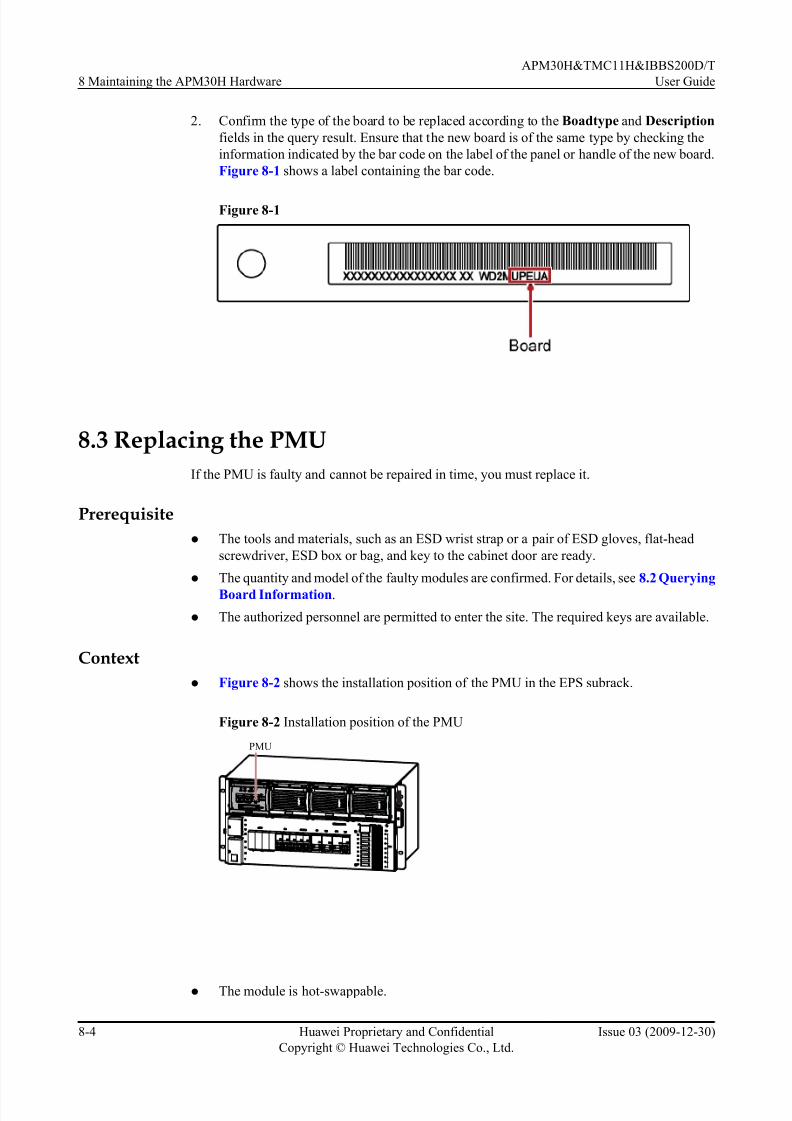
7/17/2019 Apm30 User Guide-(v200r303_03)
http://slidepdf.com/reader/full/apm30-user-guide-v200r30303 146/181
2. Confirm the type of the board to be replaced according to the Boadtype and Description
fields in the query result. Ensure that the new board is of the same type by checking the
information indicated by the bar code on the label of the panel or handle of the new board.
Figure 8-1 shows a label containing the bar code.
Figure 8-1
8.3 Replacing the PMU
If the PMU is faulty and cannot be repaired in time, you must replace it.
Prerequisite
l The tools and materials, such as an ESD wrist strap or a pair of ESD gloves, flat-head
screwdriver, ESD box or bag, and key to the cabinet door are ready.
l The quantity and model of the faulty modules are confirmed. For details, see 8.2 Querying
Board Information.
l The authorized personnel are permitted to enter the site. The required keys are available.
Context
l Figure 8-2 shows the installation position of the PMU in the EPS subrack.
Figure 8-2 Installation position of the PMU
PMU
l The module is hot-swappable.
8 Maintaining the APM30H Hardware
APM30H&TMC11H&IBBS200D/T
User Guide
8-4 Huawei Proprietary and Confidential
Copyright © Huawei Technologies Co., Ltd.
Issue 03 (2009-12-30)
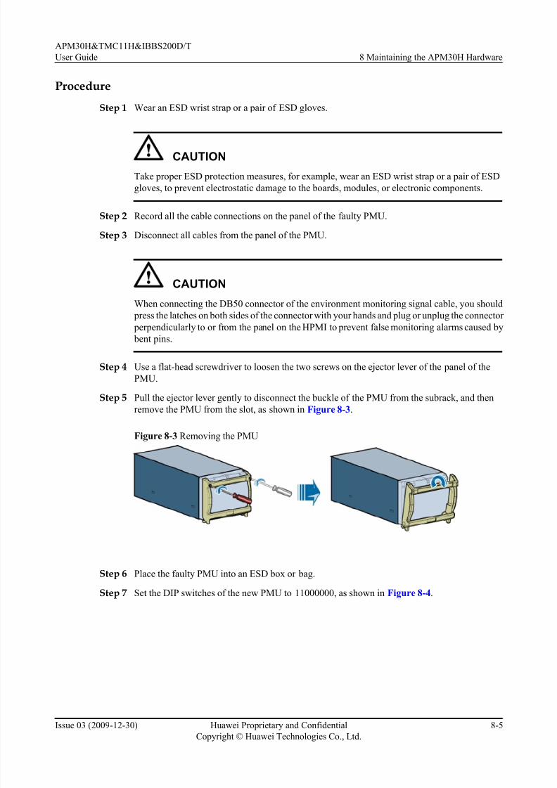
7/17/2019 Apm30 User Guide-(v200r303_03)
http://slidepdf.com/reader/full/apm30-user-guide-v200r30303 147/181
Procedure
Step 1 Wear an ESD wrist strap or a pair of ESD gloves.
CAUTION
Take proper ESD protection measures, for example, wear an ESD wrist strap or a pair of ESD
gloves, to prevent electrostatic damage to the boards, modules, or electronic components.
Step 2 Record all the cable connections on the panel of the faulty PMU.
Step 3 Disconnect all cables from the panel of the PMU.
CAUTION
When connecting the DB50 connector of the environment monitoring signal cable, you should
press the latches on both sides of the connector with your hands and plug or unplug the connector
perpendicularly to or from the panel on the HPMI to prevent false monitoring alarms caused by
bent pins.
Step 4 Use a flat-head screwdriver to loosen the two screws on the ejector lever of the panel of the
PMU.
Step 5 Pull the ejector lever gently to disconnect the buckle of the PMU from the subrack, and then
remove the PMU from the slot, as shown in Figure 8-3.
Figure 8-3 Removing the PMU
Step 6 Place the faulty PMU into an ESD box or bag.
Step 7 Set the DIP switches of the new PMU to 11000000, as shown in Figure 8-4.
APM30H&TMC11H&IBBS200D/T
User Guide 8 Maintaining the APM30H Hardware
Issue 03 (2009-12-30) Huawei Proprietary and Confidential
Copyright © Huawei Technologies Co., Ltd.
8-5
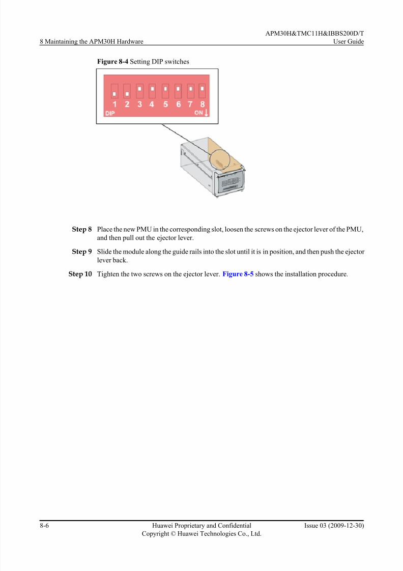
7/17/2019 Apm30 User Guide-(v200r303_03)
http://slidepdf.com/reader/full/apm30-user-guide-v200r30303 148/181
Figure 8-4 Setting DIP switches
Step 8 Place the new PMU in the corresponding slot, loosen the screws on the ejector lever of the PMU,
and then pull out the ejector lever.
Step 9 Slide the module along the guide rails into the slot until it is in position, and then push the ejector
lever back.
Step 10 Tighten the two screws on the ejector lever. Figure 8-5 shows the installation procedure.
8 Maintaining the APM30H Hardware
APM30H&TMC11H&IBBS200D/T
User Guide
8-6 Huawei Proprietary and Confidential
Copyright © Huawei Technologies Co., Ltd.
Issue 03 (2009-12-30)

7/17/2019 Apm30 User Guide-(v200r303_03)
http://slidepdf.com/reader/full/apm30-user-guide-v200r30303 149/181
Figure 8-5 Installing the PMU
Step 11 Connect the cables to the ports on the panel of the new PMU based on the cable connection
records.
Step 12 Check the status of the indicators to determine whether the new module works properly. For
details on the status of the indicators, see PMU.
Step 13 Take off the ESD wrist strap or gloves, and pack up all the tools.
----End
Postrequisite
l Place the replaced module into the ESD box or bag. Then, place the ESD box or bag into
a carton padded with foam or into the packing box of the new module.
l Fill in the fault form with the details of the replaced module.
l Contact the local Huawei office to handle the faulty module.
8.4 Replacing the PSUIf the PSU is faulty and cannot be repaired in time, you must replace it.
APM30H&TMC11H&IBBS200D/T
User Guide 8 Maintaining the APM30H Hardware
Issue 03 (2009-12-30) Huawei Proprietary and Confidential
Copyright © Huawei Technologies Co., Ltd.
8-7

7/17/2019 Apm30 User Guide-(v200r303_03)
http://slidepdf.com/reader/full/apm30-user-guide-v200r30303 150/181
Prerequisite
l The tools and materials, such as an ESD wrist strap or a pair of ESD gloves, flat-head
screwdriver, ESD box or bag, and key to the cabinet door are ready.
l The quantity and model of the faulty modules are confirmed. For details, see 8.2 Querying
Board Information.
l The authorized personnel are permitted to enter the site. The required keys are available.
Context
l Figure 8-6 shows the installation position of the PSU in the EPS subrack.
Figure 8-6 Installation position of the PSU
PSU
l The module is hot-swappable.
Procedure
Step 1 Wear an ESD wrist strap or a pair of ESD gloves.
CAUTION
Take proper ESD protection measures, for example, wear an ESD wrist strap or a pair of ESD
gloves, to prevent electrostatic damage to the boards, modules, or electronic components.
Step 2 Use a flat-head screwdriver to loosen the two screws on the ejector lever of the panel of the PSU.
Step 3 Pull the ejector lever gently to disconnect the buckle of the PSU from the subrack, and then
remove the PSU from the slot, as shown in Figure 8-7.
Figure 8-7 Removing the PSU
8 Maintaining the APM30H Hardware
APM30H&TMC11H&IBBS200D/T
User Guide
8-8 Huawei Proprietary and Confidential
Copyright © Huawei Technologies Co., Ltd.
Issue 03 (2009-12-30)
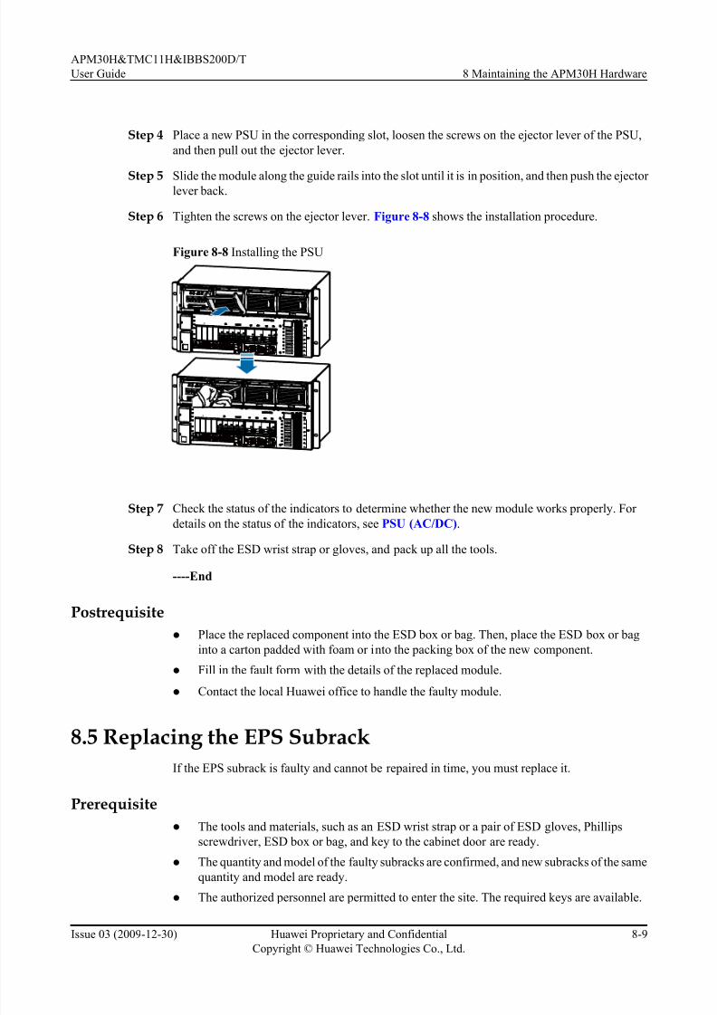
7/17/2019 Apm30 User Guide-(v200r303_03)
http://slidepdf.com/reader/full/apm30-user-guide-v200r30303 151/181
Step 4 Place a new PSU in the corresponding slot, loosen the screws on the ejector lever of the PSU,
and then pull out the ejector lever.
Step 5 Slide the module along the guide rails into the slot until it is in position, and then push the ejector lever back.
Step 6 Tighten the screws on the ejector lever. Figure 8-8 shows the installation procedure.
Figure 8-8 Installing the PSU
COMIN COMOUT COM485
COMIN COMOUT COM485
Step 7 Check the status of the indicators to determine whether the new module works properly. For
details on the status of the indicators, see PSU (AC/DC).
Step 8 Take off the ESD wrist strap or gloves, and pack up all the tools.
----End
Postrequisite
l Place the replaced component into the ESD box or bag. Then, place the ESD box or bag
into a carton padded with foam or into the packing box of the new component.
l Fill in the fault form with the details of the replaced module.
l Contact the local Huawei office to handle the faulty module.
8.5 Replacing the EPS Subrack
If the EPS subrack is faulty and cannot be repaired in time, you must replace it.
Prerequisite
l The tools and materials, such as an ESD wrist strap or a pair of ESD gloves, Phillips
screwdriver, ESD box or bag, and key to the cabinet door are ready.
l The quantity and model of the faulty subracks are confirmed, and new subracks of the same
quantity and model are ready.
l The authorized personnel are permitted to enter the site. The required keys are available.
APM30H&TMC11H&IBBS200D/T
User Guide 8 Maintaining the APM30H Hardware
Issue 03 (2009-12-30) Huawei Proprietary and Confidential
Copyright © Huawei Technologies Co., Ltd.
8-9

7/17/2019 Apm30 User Guide-(v200r303_03)
http://slidepdf.com/reader/full/apm30-user-guide-v200r30303 152/181
Context
l Replacing the EPS subrack disrupts all the services carried by the base station.
l It takes about 30 minutes to replace the EPS subrack.
Procedure
Step 1 Wear an ESD wrist strap or a pair of ESD gloves.
CAUTION
Take proper ESD protection measures, for example, wear an ESD wrist strap or a pair of ESD
gloves, to prevent electrostatic damage to the boards, modules, or electronic components.
Step 2 Set the MCB labeled BAT on the panel of the EPS subrack to OFF.
Step 3 Set the three PSU MCBs on the panel of the EPS subrack to OFF.
Step 4 Turn off the AC input of the APM30H.
Step 5 Disconnect the ground cable of the EPS subrack from the ground bar on the left side of the
cabinet.
Step 6 Remove the PMU and the PSU in the EPS subrack. For details, see 8.3 Replacing the PMU
and 8.4 Replacing the PSU respectively.
Step 7 Use a Phillips screwdriver to remove the cable support on the right side of the EPS subrack.
Step 8 Label the cables that are delivered with the EPS subrack and connected to the right side of the
EPS subrack, and then disconnect the cables.
Step 9 Loosen the screws on the AC protecting hood on the left side of the EPS subrack , and then
remove the protecting hood.
Step 10 Label the AC input power cable and AC output power cable on the left side of the EPS subrack,
and then disconnect the cables.
CAUTION
The PE wire of the AC input power cable is connected to a hexagonal screw on a mounting ear
of the EPS subrack. The hexagonal screw must be stored properly after the PE wire is
disconnected.
Step 11 Label the DC output cable on the right side of the EPS subrack, and then disconnect the cable.
Step 12 Remove the remaining seven retention screws on both sides of the EPS subrack, and slowly pull
the subrack out of the cabinet, as shown in Figure 8-9.
8 Maintaining the APM30H Hardware
APM30H&TMC11H&IBBS200D/T
User Guide
8-10 Huawei Proprietary and Confidential
Copyright © Huawei Technologies Co., Ltd.
Issue 03 (2009-12-30)

7/17/2019 Apm30 User Guide-(v200r303_03)
http://slidepdf.com/reader/full/apm30-user-guide-v200r30303 153/181
Figure 8-9 Replacing the EPS subrack
CAUTION
The EPS subrack is heavy. Therefore, you need to hold the subrack with one hand, support the
bottom with the other hand, and slowly pull the subrack out. This prevents the subrack fromfalling and ensures personal safety.
Step 13 Place the faulty EPS subrack into an ESD box or bag.
Step 14 Slide the new EPS subrack into the original installation position, and then tighten the retention
screws on both sides of the subrack.
Step 15 Reinstall the PMU and the PSU in the corresponding slots in the new EPS subrack.
Step 16 Secure the interconnection terminals to the original support, and then install the support on the
right side of the cabinet.
Step 17 Connect the cables to the ports on the panel of the new EPS subrack based on the cable connectionrecords.
CAUTION
The PE wire of the AC input power cable must be connected to the hexagonal screw that is
removed in Step 10. Otherwise, the level of reliability is low.
Step 18 Secure the AC protecting hood to the left side of the EPS subrack, and then tighten the screws.
Step 19 Turn on the AC input of the APM30H.
APM30H&TMC11H&IBBS200D/T
User Guide 8 Maintaining the APM30H Hardware
Issue 03 (2009-12-30) Huawei Proprietary and Confidential
Copyright © Huawei Technologies Co., Ltd.
8-11

7/17/2019 Apm30 User Guide-(v200r303_03)
http://slidepdf.com/reader/full/apm30-user-guide-v200r30303 154/181
Step 20 Set the three PSU MCBs on the panel of the EPS subrack to ON.
Step 21 Set the MCB labeled BAT on the EPS subrack to ON.
Step 22 Check the status of the indicators on the PMU and PSU to determine whether the new EPS
subrack works properly. For details on the status of the indicators, see PMU and PSU (AC/DC).
Step 23 Take off the ESD wrist strap or gloves, and pack up all the tools.
----End
Postrequisite
l Place the replaced component into the ESD box or bag. Then, place the ESD box or bag
into a carton padded with foam or into the packing box of the new component.
l Fill in the fault form with the details of the replaced component.
l Contact the local Huawei office to handle the faulty component.
8.6 Replacing the AC Surge Protector
If the AC surge protector is faulty, you must replace it.
Prerequisite
l The tools and materials, such as an ESD wrist strap or a pair of ESD gloves, ESD box or
bag, and key to the cabinet door are ready.
l
The quantity and model of the faulty modules are confirmed, and new modules of the samequantity and model are ready.
l The authorized personnel are permitted to enter the site. The required keys are available.
Context
l Figure 8-10 shows the installation position of the AC surge protector in the EPS subrack.
Figure 8-10 Installation position of the AC surge protector
l
When the color of the protecting hood on the front panel of the surge protector changesfrom green to red, the protector is faulty and you must replace it.
8 Maintaining the APM30H Hardware
APM30H&TMC11H&IBBS200D/T
User Guide
8-12 Huawei Proprietary and Confidential
Copyright © Huawei Technologies Co., Ltd.
Issue 03 (2009-12-30)

7/17/2019 Apm30 User Guide-(v200r303_03)
http://slidepdf.com/reader/full/apm30-user-guide-v200r30303 155/181
Procedure
Step 1 Wear an ESD wrist strap or a pair of ESD gloves.
CAUTION
Take proper ESD protection measures, for example, wear an ESD wrist strap or a pair of ESD
gloves, to prevent electrostatic damage to the boards, modules, or electronic components.
Step 2 Press the upper and lower ends of the surge protector, and then remove the protector, as shown
in Figure 8-11.
Figure 8-11 Removing the surge protector
Step 3 Place the faulty AC surge protector into an ESD box or bag.
Step 4 Place the new surge protector in the corresponding slot, and then push it until it is securely
installed.
Step 5 Check the color of the protecting hood on the front panel of the surge protector to determine
whether the new surge protector works properly. When the surge protector works properly, the
color is green.
Step 6 Take off the ESD wrist strap or gloves, and pack up all the tools.
----End
Postrequisite
l Place the replaced module into the ESD box or bag. Then, place the ESD box or bag into
a carton padded with foam or into the packing box of the new module.
l Fill in the fault form with the details of the replaced module.
l Contact the local Huawei office to handle the faulty module.
8.7 Replacing the Alarm Warning Fuse
When certain power equipment, which has high current requirements, is connected to a DCoutput port on the EPS subrack, the fuse on the port need to be replaced if it cannot meet the
APM30H&TMC11H&IBBS200D/T
User Guide 8 Maintaining the APM30H Hardware
Issue 03 (2009-12-30) Huawei Proprietary and Confidential
Copyright © Huawei Technologies Co., Ltd.
8-13

7/17/2019 Apm30 User Guide-(v200r303_03)
http://slidepdf.com/reader/full/apm30-user-guide-v200r30303 156/181
high-current requirement. Replacing the fuse that controls the port for supplying power to the
BBU disrupts all the services carried by the base station.
Prerequisite
l The tools and materials, such as an ESD wrist strap or a pair of ESD gloves, new fuse, ESD
box or bag, and key to the cabinet door are ready.
l The quantity and model of the faulty fuses are confirmed, and new fuses of the same quantity
and model are ready.
l The authorized personnel are permitted to enter the site. The required keys are available.
Context
l Figure 8-12 shows the installation position of the alarm warning fuse in the EPS subrack.
Figure 8-12 Installation position of the alarm warning fuse
l The alarm warning fuse is hot-swappable.
CAUTION
The specifications of the fuse vary according to the ambient temperature. For details on the
derating of the fuse, see the general specifications of the fuse. If the fuse works at a normal
temperature of 25°C, the operating current cannot be greater than 75% of its rated current.
Procedure
Step 1 Wear an ESD wrist strap or a pair of ESD gloves.
CAUTION
Take proper ESD protection measures, for example, wear an ESD wrist strap or a pair of ESD
gloves, to prevent electrostatic damage to the boards, modules, or electronic components.
8 Maintaining the APM30H Hardware
APM30H&TMC11H&IBBS200D/T
User Guide
8-14 Huawei Proprietary and Confidential
Copyright © Huawei Technologies Co., Ltd.
Issue 03 (2009-12-30)

7/17/2019 Apm30 User Guide-(v200r303_03)
http://slidepdf.com/reader/full/apm30-user-guide-v200r30303 157/181
Step 2 Take the extraction tool out of the mounting ear on the right side of the EPS subrack.
Figure 8-13 shows the exterior and position of the extraction tool.
Figure 8-13 Position of the extraction tool in the cabinet
Step 3 Use the extraction tool to remove the faulty fuse, as shown in Figure 8-14.
Figure 8-14 Removing the faulty fuse
Step 4 Place the faulty alarm warning fuse into an ESD box or bag.
Step 5 Insert the new fuse into the corresponding port.
Step 6 Set the MCB for the new fuse to ON and check the running status of the related modules to
determine whether the fuse works properly.
Step 7 Take off the ESD wrist strap or gloves, and pack up all the tools.
----End
APM30H&TMC11H&IBBS200D/T
User Guide 8 Maintaining the APM30H Hardware
Issue 03 (2009-12-30) Huawei Proprietary and Confidential
Copyright © Huawei Technologies Co., Ltd.
8-15

7/17/2019 Apm30 User Guide-(v200r303_03)
http://slidepdf.com/reader/full/apm30-user-guide-v200r30303 158/181
Postrequisite
l Place the replaced component into the ESD box or bag. Then, place the ESD box or bag
into a carton padded with foam or into the packing box of the new component.
l Fill in the fault form with the details of the replaced component.
8.8 Replacing the Fan Box in the APM30H
If the fan box in the APM30H is faulty, you must replace it.
Prerequisite
l The tools and materials, such as an ESD wrist strap or a pair of ESD gloves, Phillips
screwdriver, ESD box or bag, and key to the cabinet door are ready.
l The quantity and model of the faulty fan boxes are confirmed. For details, see 8.2 Querying
Board Information.l The authorized personnel are permitted to enter the site. The required keys are available.
Context
l The fan box in the APM30H houses the HPMI, CMUA, and fan. If any of the components
is faulty, the fan box must be replaced.
l It takes about 20 minutes to replace the fan box.
Procedure
Step 1 Wear an ESD wrist strap or a pair of ESD gloves.
CAUTION
Take proper ESD protection measures, for example, wear an ESD wrist strap or a pair of ESD
gloves, to prevent electrostatic damage to the boards, modules, or electronic components.
Step 2 Remove the fuse corresponding to the port labeled LOAD0. For details, see 8.7 Replacing the
Alarm Warning Fuse.
Step 3 Record all the cable connections on the panel of the faulty fan box.Step 4 Disconnect all cables from the panel of the faulty fan box.
8 Maintaining the APM30H Hardware
APM30H&TMC11H&IBBS200D/T
User Guide
8-16 Huawei Proprietary and Confidential
Copyright © Huawei Technologies Co., Ltd.
Issue 03 (2009-12-30)

7/17/2019 Apm30 User Guide-(v200r303_03)
http://slidepdf.com/reader/full/apm30-user-guide-v200r30303 159/181
NOTE
Remove the RJ-45 connectors linked to the COM_IN, COM_OUT, and ELU ports on the panel of the CMUA
through the holes in the baffle plate on the ports, as shown in Figure 8-15.
Figure 8-15 Top view of the fan box in the APM30H
Step 5 Remove the retention screws on the mounting ears of the fan box, and then remove the box from
the cabinet slowly, as shown in Figure 8-16.
Figure 8-16 Removing the fan box from the APM30H
DANGER
When removing the fan box, do not touch the air inlet at the bottom of the fan box.
Step 6 Place the faulty fan box into an ESD box or bag.
Step 7 Slide the new fan box into the installation position, and then tighten the retention screws on themounting ears of the fan box.
APM30H&TMC11H&IBBS200D/T
User Guide 8 Maintaining the APM30H Hardware
Issue 03 (2009-12-30) Huawei Proprietary and Confidential
Copyright © Huawei Technologies Co., Ltd.
8-17

7/17/2019 Apm30 User Guide-(v200r303_03)
http://slidepdf.com/reader/full/apm30-user-guide-v200r30303 160/181
Step 8 Connect the cables to the ports on the front panel of the fan box based on the cable connection
records, and then check and ensure that the cables are properly and correctly connected.
NOTE
You must plug or unplug the DB50 connector of the environment monitoring signal cable perpendicularly
to or from the panel on the HPMI with your hands to prevent false monitoring alarms caused by bent pins.
Step 9 Link the connector at one end of the power cable of the fan box in the APM30H to the port
labeled LOAD0 on the panel of the fan box of the EPS subrack.
Step 10 Check the status of the indicators to determine whether the new fan box works properly. For
details on the status of the indicators, see CMUA.
Step 11 Take off the ESD wrist strap or gloves, and pack up all the tools.
----End
Postrequisite
l Place the replaced component into the ESD box or bag. Then, place the ESD box or bag
into a carton padded with foam or into the packing box of the new component.
l Fill in the fault form with the details of the replaced component.
l Contact the local Huawei office to handle the faulty component.
8.9 Replacing the Fan on the Front Door of the APM30H
If the fan on the front door of the APM30H is faulty and cannot be repaired in time, you must
replace it.
Prerequisite
l The tools and materials, such as an ESD wrist strap or a pair of ESD gloves, Phillips
screwdriver, ESD box or bag, and key to the cabinet door are ready.
l The quantity and model of the faulty fans are confirmed, and new fans of the same quantity
and model are ready.
l The authorized personnel are permitted to enter the site. The required keys are available.
Context
l Figure 8-17 shows the installation position of the fan on the front door in the APM30H.
8 Maintaining the APM30H Hardware
APM30H&TMC11H&IBBS200D/T
User Guide
8-18 Huawei Proprietary and Confidential
Copyright © Huawei Technologies Co., Ltd.
Issue 03 (2009-12-30)

7/17/2019 Apm30 User Guide-(v200r303_03)
http://slidepdf.com/reader/full/apm30-user-guide-v200r30303 161/181
Figure 8-17 Installation position of the fan on the front door in the APM30H
l It takes about 20 minutes to replace the fan.
Procedure
Step 1 Wear an ESD wrist strap or a pair of ESD gloves.
CAUTION
Take proper ESD protection measures, for example, wear an ESD wrist strap or a pair of ESD
gloves, to prevent electrostatic damage to the boards, modules, or electronic components.
Step 2 Remove the fuse corresponding to the port labeled LOAD0. For details, see 8.7 Replacing the
Alarm Warning Fuse.
Step 3 Remove the connector linked to the port labeled FAN_EXT on the panel of the CMUA to power
off the fan on the front door of the APM30H.
Step 4 Loosen the screws on the cover plate of the transfer board of the fan, and then remove the cover
plate.
Step 5 Label the cables connected to the faulty fan, and then disconnect the cables, as shown in 1 of Figure 8-18.
Step 6 Remove the eight retention screws on the cover plate of the fan and remove the cover plate, as
shown in 2 of Figure 8-18.
Step 7 Remove the baffle and rubber caps on the cable outlets on the side of the fan cavity. Then, pull
out the cable for fans, as shown in 3 of Figure 8-18.
APM30H&TMC11H&IBBS200D/T
User Guide 8 Maintaining the APM30H Hardware
Issue 03 (2009-12-30) Huawei Proprietary and Confidential
Copyright © Huawei Technologies Co., Ltd.
8-19

7/17/2019 Apm30 User Guide-(v200r303_03)
http://slidepdf.com/reader/full/apm30-user-guide-v200r30303 162/181
Figure 8-18 Removing the fan on the front door of the APM30H
Step 8 Remove the four retention screws on the support plate of the fan and pull the support plate and
the fan out of the cabinet, as shown in 4 of Figure 8-18.
Step 9 Remove the four screws fixing the fan from the support plate, and then remove the fan.
Step 10 Lead the cables of the new fan through the cable outlets in the support plate. Then, tighten the
four screws of the fan.
Step 11 Install the cover plate of the fan back to the fan cavity after the fan is installed and tighten the
four retention screws.
Step 12 Lead the fan cable through the cable outlets of the fan cavity. Then, add the rubber caps and
baffle to the cable.
Step 13 Tighten the two screws on the baffle.
Step 14 Reconnect the cables of the fan to the fan transfer board based on the cable connection records.
Then, install the cover plate of the fan transfer board.
Step 15 Re-link the connector to the port labeled FAN_EXT on the panel of the CMUA.
Step 16 Check the running of the fans and the status of the indicators on the CMUA to determine whether
the new fan works properly. For details on the status of the indicators, see CMUA.
Step 17 Take off the ESD wrist strap or gloves, and pack up all the tools.
----End
8 Maintaining the APM30H Hardware
APM30H&TMC11H&IBBS200D/T
User Guide
8-20 Huawei Proprietary and Confidential
Copyright © Huawei Technologies Co., Ltd.
Issue 03 (2009-12-30)

7/17/2019 Apm30 User Guide-(v200r303_03)
http://slidepdf.com/reader/full/apm30-user-guide-v200r30303 163/181
Postrequisite
l Place the replaced component into the ESD box or bag. Then, place the ESD box or bag
into a carton padded with foam or into the packing box of the new component.
l Fill in the fault form with the details of the replaced component.
l Contact the local Huawei office to handle the faulty component.
8.10 Replacing the Heater
If a heater in the APM30H or the TMC11H is faulty and cannot be repaired in time, you must
replace it.
Prerequisite
l The tools and materials, such as an ESD wrist strap or a pair of ESD gloves, diagonal pliers,
flat-head screwdriver, Phillips screwdriver, insulation screwdriver, ESD box or bag, and
key to the cabinet door are ready.
l The quantity and model of the faulty heaters are confirmed, and new heaters of the same
quantity and model and several cable ties are ready.
l The authorized personnel are permitted to enter the site. The required keys are available.
Context
The heater can be installed in the 1 U transmission space based on the actual condition.
WARNING
After the installation, do not change the position of the heater during the routine operation.
Procedure
Step 1 Wear an ESD wrist strap or a pair of ESD gloves.
CAUTION
Take proper ESD protection measures, for example, wear an ESD wrist strap or a pair of ESD
gloves, to prevent electrostatic damage to the boards, modules, or electronic components.
Step 2 Set the AC output MCB labeled AC OUTPUT on the panel of the EPS subrack to OFF.
Step 3 Remove the connector at one end of the power cable from the heater.
Step 4 Remove the four screws on the panel of the heater. Hold the heater with one hand, and pull theheater out of the cabinet with the other hand slightly, as shown in Figure 8-19.
APM30H&TMC11H&IBBS200D/T
User Guide 8 Maintaining the APM30H Hardware
Issue 03 (2009-12-30) Huawei Proprietary and Confidential
Copyright © Huawei Technologies Co., Ltd.
8-21

7/17/2019 Apm30 User Guide-(v200r303_03)
http://slidepdf.com/reader/full/apm30-user-guide-v200r30303 164/181
Figure 8-19 Removing the faulty heater
Step 5 Place the new heater in its installation position. Hold the new heater with one hand, and push it
into the cabinet with the other hand until the mounting ears are in contact with the columns.
Step 6 Tighten the two screws on both sides of the heater.
Step 7 Re-link the connector at one end of the power cable to the input port of the heater, as shown in
Figure 8-20.
Figure 8-20 Installing the new heater
Step 8 Set the AC output MCB labeled AC OUTPUT on the panel of the EPS subrack to ON.
Step 9 Take off the ESD wrist strap or gloves, and pack up all the tools.
----End
Postrequisite
l Place the replaced heater into the ESD box or bag. Then, place the ESD box or bag into a
carton padded with foam or into the packing box of the new heater.
l Fill in the fault form with the details of the replaced heater.
l Contact the local Huawei office to handle the faulty heater.
8 Maintaining the APM30H Hardware
APM30H&TMC11H&IBBS200D/T
User Guide
8-22 Huawei Proprietary and Confidential
Copyright © Huawei Technologies Co., Ltd.
Issue 03 (2009-12-30)

7/17/2019 Apm30 User Guide-(v200r303_03)
http://slidepdf.com/reader/full/apm30-user-guide-v200r30303 165/181
8.11 Replacing the Fan Box in the TMC11H
If the fan box in the TMC11H is faulty, you must replace it.
Prerequisite
l The tools and materials, such as an ESD wrist strap or a pair of ESD gloves, Phillips
screwdriver, ESD box or bag, and key to the cabinet door are ready.
l The quantity and model of the faulty fan boxes are confirmed. For details, see 8.2 Querying
Board Information.
l The authorized personnel are permitted to enter the site. The required keys are available.
Context
l The fan box in the TMC11H houses the HPMI, CMUA, and fan. If any of the componentsis faulty, the fan box must be replaced.
l It takes about 20 minutes to replace the fan box.
Procedure
Step 1 Wear an ESD wrist strap or a pair of ESD gloves.
CAUTION
Take proper ESD protection measures, for example, wear an ESD wrist strap or a pair of ESD
gloves, to prevent electrostatic damage to the boards, modules, or electronic components.
Step 2 Set the MCB labeled FAN on the DCDU-03 to OFF to power off the fan box.
Step 3 Record all the cable connections on the panel of the faulty fan box.
Step 4 Disconnect all cables from the panel of the faulty fan box.
NOTE
Remove the RJ-45 connectors linked to the COM_IN, COM_OUT, and ELU ports on the panel of the
CMUA through the holes in the baffle plate on the ports, as shown in Figure 8-21.
Figure 8-21 Top view of the fan box in the TMC11H
APM30H&TMC11H&IBBS200D/T
User Guide 8 Maintaining the APM30H Hardware
Issue 03 (2009-12-30) Huawei Proprietary and Confidential
Copyright © Huawei Technologies Co., Ltd.
8-23

7/17/2019 Apm30 User Guide-(v200r303_03)
http://slidepdf.com/reader/full/apm30-user-guide-v200r30303 166/181
Step 5 Remove the retention screws on the mounting ears of the fan box, and then remove the box from
the cabinet slowly, as shown in Figure 8-22.
Figure 8-22 Removing the fan box from the TMC11H
DANGER
When removing the fan box, do not touch the air inlet at the bottom of the fan box.
Step 6 Slide the new fan box into the installation position, and then tighten the retention screws on the
mounting ears of the fan box.
Step 7 Connect the cables to the ports on the front panel of the fan box based on the cable connection
records, and then check and ensure that the cables are properly and correctly connected.
Step 8 Set the MCB labeled FAN on the DCDU-03 to ON to power on the fan box.
Step 9 Check the status of the indicators to determine whether the new fan box works properly. For
details on the status of the indicators, see CMUA.
Step 10 Take off the ESD wrist strap or gloves, and pack up all the tools.
----End
Postrequisite
l Place the replaced component into the ESD box or bag. Then, place the ESD box or bag
into a carton padded with foam or into the packing box of the new component.
l Fill in the fault form with the details of the replaced component.
l Contact the local Huawei office to handle the faulty component.
8.12 Replacing the Batteries
If batteries are faulty or old, you must replace them. Generally, batteries are replaced in batches.
8 Maintaining the APM30H Hardware
APM30H&TMC11H&IBBS200D/T
User Guide
8-24 Huawei Proprietary and Confidential
Copyright © Huawei Technologies Co., Ltd.
Issue 03 (2009-12-30)

7/17/2019 Apm30 User Guide-(v200r303_03)
http://slidepdf.com/reader/full/apm30-user-guide-v200r30303 167/181
Prerequisite
l The tools and materials, such as an ESD wrist strap or a pair of ESD gloves, Phillips
screwdriver, ESD box or bag, and key to the cabinet door are ready.
l The quantity and model of the faulty batteries are confirmed, and new batteries of the same
quantity and model are ready.
l The authorized personnel are permitted to enter the site. The required keys are available.
Context
DANGER
During the replacement, short circuits or reverse connections cannot exist between the positive
and negative poles of the batteries. All the tools such as wrenches and screwdrivers must be
coated with insulating tubes. This prevents the batteries from being burned and ensures personal
safety.
Procedure
Step 1 Wear an ESD wrist strap or a pair of ESD gloves.
CAUTION
Take proper ESD protection measures, for example, wear an ESD wrist strap or a pair of ESD
gloves, to prevent electrostatic damage to the boards, modules, or electronic components.
Step 2 Set the MCB labeled BAT on the panel of the EPS subrack in the APM30 cabinet to OFF.
Step 3 Remove the cover plate on the batteries, as shown in Figure 8-23.
APM30H&TMC11H&IBBS200D/T
User Guide 8 Maintaining the APM30H Hardware
Issue 03 (2009-12-30) Huawei Proprietary and Confidential
Copyright © Huawei Technologies Co., Ltd.
8-25
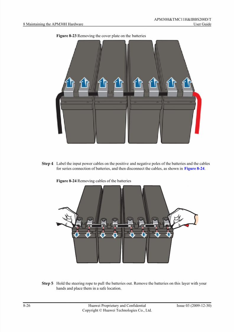
7/17/2019 Apm30 User Guide-(v200r303_03)
http://slidepdf.com/reader/full/apm30-user-guide-v200r30303 168/181
Figure 8-23 Removing the cover plate on the batteries
Step 4 Label the input power cables on the positive and negative poles of the batteries and the cables
for series connection of batteries, and then disconnect the cables, as shown in Figure 8-24.
Figure 8-24 Removing cables of the batteries
Step 5 Hold the steering rope to pull the batteries out. Remove the batteries on this layer with your
hands and place them in a safe location.
8 Maintaining the APM30H Hardware
APM30H&TMC11H&IBBS200D/T
User Guide
8-26 Huawei Proprietary and Confidential
Copyright © Huawei Technologies Co., Ltd.
Issue 03 (2009-12-30)

7/17/2019 Apm30 User Guide-(v200r303_03)
http://slidepdf.com/reader/full/apm30-user-guide-v200r30303 169/181
NOTE
l Remove the baffle plates and batteries from top to bottom. Remove the batteries before removing the
baffle plate of the lower layer.
l Remove and place the batteries with your hands to prevent the batteries from falling.
Step 6 Install the new batteries layer by layer and connect the input power cables and the cables for
series connection of batteries based on the cable connection records.
NOTE
l Install all the batteries and baffle plates from bottom to up. Install the batteries before installing the
baffle plate of the upper layer.
l Ensure that the cables are securely and correctly connected.
Step 7 Use a multimeter to measure the voltage at both ends of the battery pack to prevent inverse
connection.
Step 8 Set the MCB labeled BAT on the panel of the EPS subrack to ON.
Step 9 Take off the ESD wrist strap or gloves, and pack up all the tools.
----End
Postrequisite
l Place the replaced batteries into the ESD box or bag. Then, place the ESD box or bag into
a carton padded with foam or into the packing box of the new batteries.
l Fill in the fault form with the details of the replaced batteries.
l Contact the local Huawei office to handle the faulty batteries.
8.13 Replacing the TEC Cooler of the IBBS200T
The TEC cooler helps dissipate the heat of storage batteries to ensure the normal operation of
the IBBS200T in high-temperature areas. If the TEC cooler is faulty and cannot be repaired in
time, you must replace it.
Prerequisite
l The tools and materials, such as an ESD wrist strap or a pair of ESD gloves, Phillips
screwdriver, ESD box or bag, and key to the cabinet door are ready.
l The quantity and model of the faulty modules are confirmed, and new modules of the same
quantity and model are ready.
l The authorized personnel are permitted to enter the site. The required keys are available.
Context
l Figure 8-25 shows the installation position of the TEC cooler in the IBBS200T.
APM30H&TMC11H&IBBS200D/T
User Guide 8 Maintaining the APM30H Hardware
Issue 03 (2009-12-30) Huawei Proprietary and Confidential
Copyright © Huawei Technologies Co., Ltd.
8-27

7/17/2019 Apm30 User Guide-(v200r303_03)
http://slidepdf.com/reader/full/apm30-user-guide-v200r30303 170/181
Figure 8-25 Installation position of the TEC cooler
TEC
Procedure
Step 1 Wear an ESD wrist strap or a pair of ESD gloves.
CAUTION
Take proper ESD protection measures, for example, wear an ESD wrist strap or a pair of ESD
gloves, to prevent electrostatic damage to the boards, modules, or electronic components.
Step 2 Set the MCB labeled FAN/TEC_SW2 for the TEC cooler of the power distribution box on the
inner right side in the IBBS200T to OFF to power off the TEC cooler.
Step 3 Loosen the two retention screws fixing the CMUA on the front door, remove the cover plate,and then disconnect the power cables and alarm signal cables of the TEC cooler from the CMUA,
as shown in 1 of Figure 8-26.
8 Maintaining the APM30H Hardware
APM30H&TMC11H&IBBS200D/T
User Guide
8-28 Huawei Proprietary and Confidential
Copyright © Huawei Technologies Co., Ltd.
Issue 03 (2009-12-30)

7/17/2019 Apm30 User Guide-(v200r303_03)
http://slidepdf.com/reader/full/apm30-user-guide-v200r30303 171/181
Figure 8-26 Removing the retention screws on the CMUA
Step 4 Remove the two retention screws of the TEC protecting hood on the inner side of the front door,
as shown in 2 of Figure 8-26.
Step 5 Rotate the movable side of the TEC protecting hood clockwise by 90 degrees. Remove the six
retention screws, as shown in Figure 8-27, and then remove the TEC cooler from the subrack
of the front door.
Figure 8-27 Removing the faulty TEC cooler
APM30H&TMC11H&IBBS200D/T
User Guide 8 Maintaining the APM30H Hardware
Issue 03 (2009-12-30) Huawei Proprietary and Confidential
Copyright © Huawei Technologies Co., Ltd.
8-29

7/17/2019 Apm30 User Guide-(v200r303_03)
http://slidepdf.com/reader/full/apm30-user-guide-v200r30303 172/181
Step 6 Lead the power cables and the alarm signaling cables through the empty subrack on the front
door, and then install six M4 screws to fix the TEC cooler in the reverse direction in Figure
8-27.
Step 7 Close the TEC protecting hood, and fix the hood by using two screws.
Step 8 Connect the power cables and the alarm signaling cables that are delivered with the new cooler
to the corresponding ports on the CMUA.
Step 9 Fix the CMUA by using two screws.
Step 10 Set the MCB for the TEC cooler of the power distribution box to ON.
Step 11 Check the running of the fans and the status of the indicators on the CMUA to determine whether
the new TEC cooler works properly. For details on the status of the indicators, see CMUA.
Step 12 Take off the ESD wrist strap or gloves, and pack up all the tools.
----End
Postrequisite
l Place the replaced module into the ESD box or bag. Then, place the ESD box or bag into
a carton padded with foam or into the packing box of the new module.
l Fill in the fault form with the details of the replaced module.
l Contact the local Huawei office to handle the faulty module.
8.14 Replacing the Fan on the Front Door of the IBBS200D
If a centrifugal fan on the front door of the IBBS200D is faulty, you must replace it.
Prerequisite
l The tools and materials, such as an ESD wrist strap or a pair of ESD gloves, Phillips
screwdriver, ESD box or bag, and key to the cabinet door are ready.
l The quantity and model of the faulty fans are confirmed, and new fans of the same quantity
and model are ready.
l The authorized personnel are permitted to enter the site. The required keys are available.
Context
l Figure 8-28 shows the installation position of the fan on the front door of the IBBS200D.
8 Maintaining the APM30H Hardware
APM30H&TMC11H&IBBS200D/T
User Guide
8-30 Huawei Proprietary and Confidential
Copyright © Huawei Technologies Co., Ltd.
Issue 03 (2009-12-30)

7/17/2019 Apm30 User Guide-(v200r303_03)
http://slidepdf.com/reader/full/apm30-user-guide-v200r30303 173/181
Figure 8-28 Installation position of the fan on the front door of the IBBS200D
FAN
IBBS200D
l The fan box on the front door of the IBBS200D houses two centrifugal fans. When
maintaining the fan box, you need to replace only the faulty fan. This example describes
how to replace the fan on the left side.
l It takes about 20 minutes to replace the fan.
Procedure
Step 1 Wear an ESD wrist strap or a pair of ESD gloves.
CAUTION
Take proper ESD protection measures, for example, wear an ESD wrist strap or a pair of ESD
gloves, to prevent electrostatic damage to the boards, modules, or electronic components.
Step 2 Set the MCB labeled TEC/FAN_SW2 of the fan box to OFF on the power distribution box in
the IBBS200D to power off the fan box.
Step 3 Label the cables below the fan box, and then disconnect the cables.
Step 4 Remove the five retention screws on the fan box, and then remove the fan box, as shown in
Figure 8-29.
APM30H&TMC11H&IBBS200D/T
User Guide 8 Maintaining the APM30H Hardware
Issue 03 (2009-12-30) Huawei Proprietary and Confidential
Copyright © Huawei Technologies Co., Ltd.
8-31

7/17/2019 Apm30 User Guide-(v200r303_03)
http://slidepdf.com/reader/full/apm30-user-guide-v200r30303 174/181
Figure 8-29 Removing the fan box of the IBBS200D
Step 5 Disconnect the cables that connect the faulty fan to one side of the CMUA.
Step 6 Loosen the four retention screws of the faulty fan, and then remove the faulty fan from the fan
box, as shown in Figure 8-30.
Figure 8-30 Removing the faulty fan
Step 7 Place the new fan in the original position of the faulty fan, and hold the fan with one hand. Then,
tighten the four retention screws with the other hand by using a screwdriver.
8 Maintaining the APM30H Hardware
APM30H&TMC11H&IBBS200D/T
User Guide
8-32 Huawei Proprietary and Confidential
Copyright © Huawei Technologies Co., Ltd.
Issue 03 (2009-12-30)

7/17/2019 Apm30 User Guide-(v200r303_03)
http://slidepdf.com/reader/full/apm30-user-guide-v200r30303 175/181
Step 8 Connect the cables of the new fan to the corresponding ports on the panel of the CMUA, and
then bind the cables to the binding slot on the fan box by using cable ties.
Step 9 Install the fan box onto the front door, and tighten the five retention screws on the cover plate.
Step 10 Connect the cables to the corresponding ports on the panel below the fan box based on the cableconnection records.
Step 11 Set the MCB for the fan in the fan box to ON.
Step 12 Check the running of the fans and the status of the indicators on the CMUA to determine whether
the new fan works properly. For details on the status of the indicators, see CMUA.
Step 13 Take off the ESD wrist strap or gloves, and pack up all the tools.
----End
Postrequisite
l Place the replaced component into the ESD box or bag. Then, place the ESD box or bag
into a carton padded with foam or into the packing box of the new component.
l Fill in the fault form with the details of the replaced component.
l Contact the local Huawei office to handle the faulty component.
8.15 Replacing the CMUA
If the Central Monitoring Unit type A (CMUA) on the front panel of the IBBS200D or IBBS200T
cabinet is faulty, you must replace it.
Prerequisite
l The tools and materials, such as an ESD wrist strap or a pair of ESD gloves, Phillips
screwdriver, ESD box or bag, and key to the cabinet door are ready.
l The quantity and model of the faulty boards are confirmed. For details, see 8.2 Querying
Board Information.
l DIP settings of the CMUA varies according to cabinet. Figure 8-31 shows the DIP settings
and bit positions of the CMUA in different cabinets.
Figure 8-31 DIP settings and bit positions of the CMUA in different cabinets
NOTE
The red rectangle in Figure 8-32 shows the position for connecting to the jumper cap.
APM30H&TMC11H&IBBS200D/T
User Guide 8 Maintaining the APM30H Hardware
Issue 03 (2009-12-30) Huawei Proprietary and Confidential
Copyright © Huawei Technologies Co., Ltd.
8-33

7/17/2019 Apm30 User Guide-(v200r303_03)
http://slidepdf.com/reader/full/apm30-user-guide-v200r30303 176/181
l The authorized personnel are permitted to enter the site. The required keys are available.
Context
l
Figure 8-32 shows the installation position of the CMUA on the front door of theIBBS200D or IBBS200T.
Figure 8-32 Installation position of the CMUA
IBBS200D IBBS200T
CMUA CMUA
Procedure
Step 1 Wear an ESD wrist strap or a pair of ESD gloves.
CAUTION
Take proper ESD protection measures, for example, wear an ESD wrist strap or a pair of ESD
gloves, to prevent electrostatic damage to the boards, modules, or electronic components.
Step 2 Set the MCB labeled FAN/TEC_SW2 on the power distribution box to OFF to power off the
CMUA.
Step 3 Record all the cable connections on the panel of the faulty CMUA.
Step 4 Disconnect all cables from the panel of the faulty CMUA.
Step 5 Use a screwdriver to loosen the screws on the fan box of the IBBS200D or the CMUA box of
the IBBS200T, and then remove the fan box or CMUA box, as shown in Figure 8-33 or Figure
8-34 respectively.
8 Maintaining the APM30H Hardware
APM30H&TMC11H&IBBS200D/T
User Guide
8-34 Huawei Proprietary and Confidential
Copyright © Huawei Technologies Co., Ltd.
Issue 03 (2009-12-30)

7/17/2019 Apm30 User Guide-(v200r303_03)
http://slidepdf.com/reader/full/apm30-user-guide-v200r30303 177/181
Figure 8-33 Removing the fan box of the IBBS200D
Figure 8-34 Removing the CMUA box of the IBBS200D
APM30H&TMC11H&IBBS200D/T
User Guide 8 Maintaining the APM30H Hardware
Issue 03 (2009-12-30) Huawei Proprietary and Confidential
Copyright © Huawei Technologies Co., Ltd.
8-35
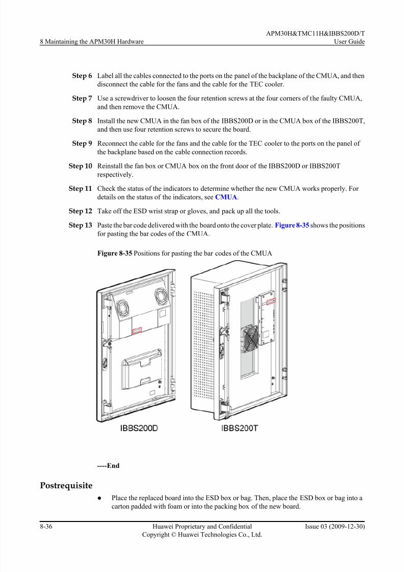
7/17/2019 Apm30 User Guide-(v200r303_03)
http://slidepdf.com/reader/full/apm30-user-guide-v200r30303 178/181
Step 6 Label all the cables connected to the ports on the panel of the backplane of the CMUA, and then
disconnect the cable for the fans and the cable for the TEC cooler.
Step 7 Use a screwdriver to loosen the four retention screws at the four corners of the faulty CMUA,and then remove the CMUA.
Step 8 Install the new CMUA in the fan box of the IBBS200D or in the CMUA box of the IBBS200T,
and then use four retention screws to secure the board.
Step 9 Reconnect the cable for the fans and the cable for the TEC cooler to the ports on the panel of
the backplane based on the cable connection records.
Step 10 Reinstall the fan box or CMUA box on the front door of the IBBS200D or IBBS200T
respectively.
Step 11 Check the status of the indicators to determine whether the new CMUA works properly. For
details on the status of the indicators, see CMUA.Step 12 Take off the ESD wrist strap or gloves, and pack up all the tools.
Step 13 Paste the bar code delivered with the board onto the cover plate. Figure 8-35 shows the positions
for pasting the bar codes of the CMUA.
Figure 8-35 Positions for pasting the bar codes of the CMUA
----End
Postrequisite
l
Place the replaced board into the ESD box or bag. Then, place the ESD box or bag into acarton padded with foam or into the packing box of the new board.
8 Maintaining the APM30H Hardware
APM30H&TMC11H&IBBS200D/T
User Guide
8-36 Huawei Proprietary and Confidential
Copyright © Huawei Technologies Co., Ltd.
Issue 03 (2009-12-30)
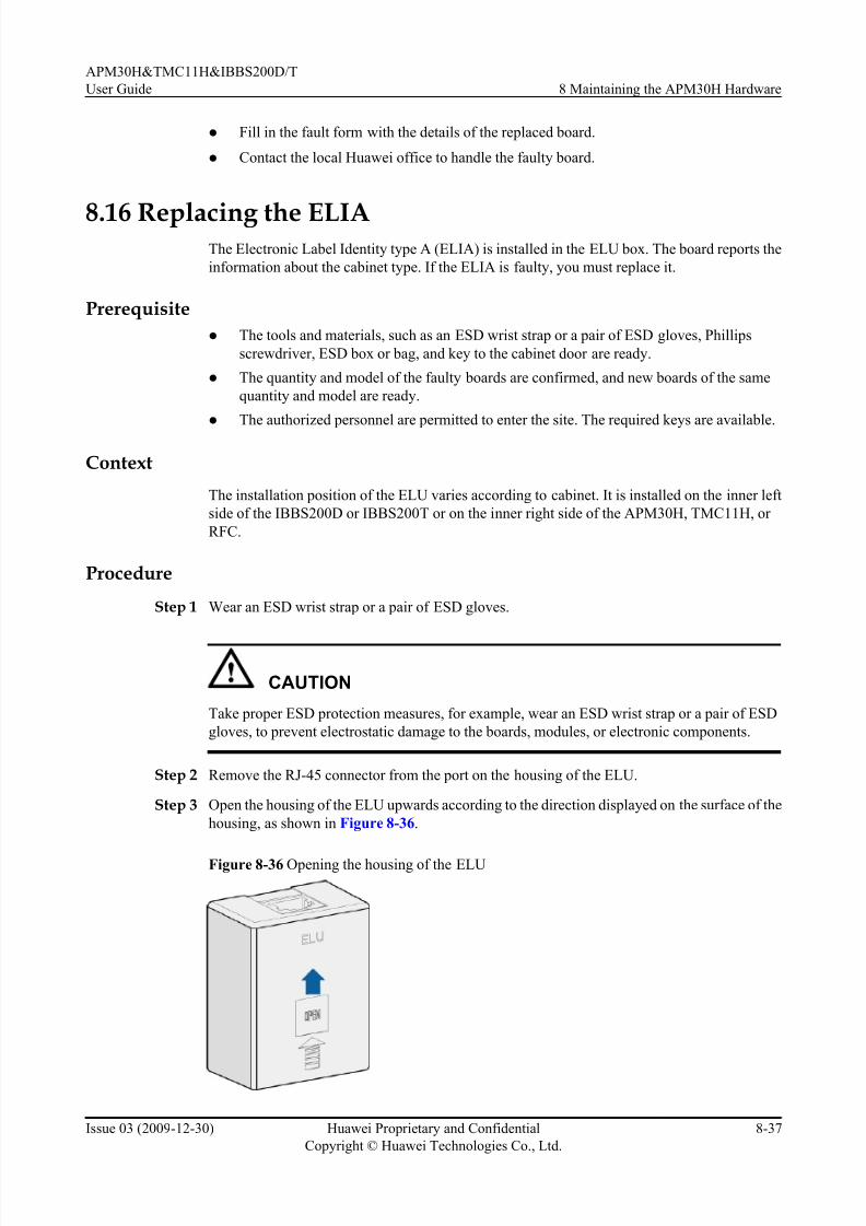
7/17/2019 Apm30 User Guide-(v200r303_03)
http://slidepdf.com/reader/full/apm30-user-guide-v200r30303 179/181
l Fill in the fault form with the details of the replaced board.
l Contact the local Huawei office to handle the faulty board.
8.16 Replacing the ELIAThe Electronic Label Identity type A (ELIA) is installed in the ELU box. The board reports the
information about the cabinet type. If the ELIA is faulty, you must replace it.
Prerequisite
l The tools and materials, such as an ESD wrist strap or a pair of ESD gloves, Phillips
screwdriver, ESD box or bag, and key to the cabinet door are ready.
l The quantity and model of the faulty boards are confirmed, and new boards of the same
quantity and model are ready.
l The authorized personnel are permitted to enter the site. The required keys are available.
Context
The installation position of the ELU varies according to cabinet. It is installed on the inner left
side of the IBBS200D or IBBS200T or on the inner right side of the APM30H, TMC11H, or
RFC.
Procedure
Step 1 Wear an ESD wrist strap or a pair of ESD gloves.
CAUTION
Take proper ESD protection measures, for example, wear an ESD wrist strap or a pair of ESD
gloves, to prevent electrostatic damage to the boards, modules, or electronic components.
Step 2 Remove the RJ-45 connector from the port on the housing of the ELU.
Step 3 Open the housing of the ELU upwards according to the direction displayed on the surface of the
housing, as shown in Figure 8-36.
Figure 8-36 Opening the housing of the ELU
APM30H&TMC11H&IBBS200D/T
User Guide 8 Maintaining the APM30H Hardware
Issue 03 (2009-12-30) Huawei Proprietary and Confidential
Copyright © Huawei Technologies Co., Ltd.
8-37

7/17/2019 Apm30 User Guide-(v200r303_03)
http://slidepdf.com/reader/full/apm30-user-guide-v200r30303 180/181
Step 4 Use a Phillips screwdriver to loosen the retention screws on the ELIA, and then remove the
ELIA, as shown in Figure 8-37.
Figure 8-37 Removing the faulty ELIA
Step 5 Install a new board, and tighten the screws on the panel of the board.
Step 6 Reinstall the housing of the ELU.
Step 7 Re-link the RJ-45 connector to the port on the housing of the ELU.
Step 8 Take off the ESD wrist strap or gloves, and pack up all the tools.
----End
Postrequisite
l
Place the replaced board into the ESD box or bag. Then, place the ESD box or bag into acarton padded with foam or into the packing box of the new board.
l Fill in the fault form with the details of the replaced board.
l Contact the local Huawei office to handle the faulty board.
8 Maintaining the APM30H Hardware
APM30H&TMC11H&IBBS200D/T
User Guide
8-38 Huawei Proprietary and Confidential
Copyright © Huawei Technologies Co., Ltd.
Issue 03 (2009-12-30)

7/17/2019 Apm30 User Guide-(v200r303_03)
http://slidepdf.com/reader/full/apm30-user-guide-v200r30303 181/181
Index
D
DIP switchUELP, 7-3
M
moduleUSLP2, 7-5
S
APM30H&TMC11H&IBBS200D/T
User Guide Index


