
With Speed. Our Expertise. Your Safety
API SERIES DIN SERIES JIS SERIES
ATLANTISS GROUPISO9001 API 600 API 6DAPI 607

Estab l ished and based in S ingapore , A t lant iss Mar ine Systems
Pte Ltd has d is t r ibutors in USA,With TUV ISO9001, TUV CE,
API 600, API 607, API 6D, our products sel l wel l in Europe, America,
South Amer ica , Southeast As ia, Middle East and Afr ica.
We are blessed with an excellent technique team engaged in researching,
developing and manufacturing high quality products of Gate Valves, Globe
Valves, Check Valves ,Ball Valves ,Butterfly Valves and Fluid Pipe fittings,
which are made strictly in accordance with standards such as API, ASME,
ASTM, EN, BS, DIN, JIS and successfully tested in many large projects.
Quality and satisfaction guaranteed is our philosophy. It is certain that long
mutual-trust cooperation with our clients from home and abroad results in
mutual benefit bright future.
API SERIES DIN SERIES JIS SERIES
Brief Introduction
ATLANTISS GROUP

API SERIES
DIN SERIES
JIS SERIES
With Speed. Our Expertise, Your Safety
API Gate Valve
API Globe Valve
API Check Valve
API Floating Ball Valve
API Trunnion Ball Valve
API Butterfly Valve
API Forged steel gate valves
API Forged steel globe valves
API Forged steel check valves
DIN Gate Valve
DIN Globe Valve
DIN Check Valve
DIN Ball Valve
JIS Gate Valve
JIS Globe Valve
JIS Check Valve
JIS Ball Valve
JIS Butterfly Valve
01-07
08-13
14-18
19-22
23-29
30-35
36-39
40-43
44-46
47-49
50-52
53-56
57-59
60-63
64-66
67-69
70-72
73-74
CONTENTS
ATLANTISS GROUP
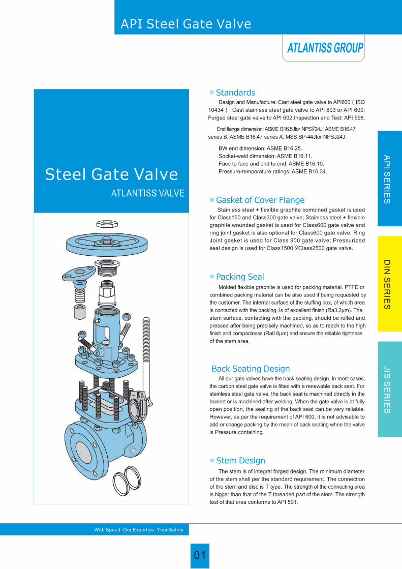
Stainless steel + flexible graphite combined gasket is used
for Class150 and Class300 gate valve; Stainless steel + flexible
graphite wounded gasket is used for Class600 gate valve and
ring joint gasket is also optional for Class600 gate valve; Ring
Joint gasket is used for Class 900 gate valve; Pressurized
seal design is used for Class1500 ЎClass2500 gate valve.
◎ Gasket of Cover Flange
Back Seating Design All our gate valves have the back seating design. In most cases,
the carbon steel gate valve is fitted with a renewable back seat. For
stainless steel gate valve, the back seat is machined directly in the
bonnet or is machined after welding. When the gate valve is at fully
open position, the sealing of the back seat can be very reliable.
However, as per the requirement of API 600, it is not advisable to
add or change packing by the mean of back seating when the valve
is Pressure containing.
The stem is of integral forged design. The minimum diameter
of the stem shall per the standard requirement. The connection
of the stem and disc is T type. The strength of the connecting area
is bigger than that of the T threaded part of the stem. The strength
test of that area conforms to API 591.
◎ Stem Design
◎ Standards Design and Manufacture: Cast steel gate valve to API600(ISO
10434); Cast stainless steel gate valve to API 603 or API 600;
Forged steel gate valve to API 602.Inspection and Test: API 598.
End flange dimension: ASME B16.5Јfor NPSЎ24Ј; ASME B16.47
series B, ASME B16.47 series A, MSS SP-44Јfor NPSЈ24Ј.
BW end dimension: ASME B16.25.
Socket-weld dimension: ASME B16.11.
Face to face and end to end: ASME B16.10.
Pressure-temperature ratings: ASME B16.34.
Molded flexible graphite is used for packing material. PTFE or
combined packing material can be also used if being requested by
the customer. The internal surface of the stuffing box, of which area
is contacted with the packing, is of excellent finish (Ra3.2μm). The
stem surface, contacting with the packing, should be rolled and
pressed after being precisely machined, so as to reach to the high
finish and compactness (Ra0.8μm) and ensure the reliable tightness
of the stem area.
◎ Packing Seal
01
Steel Gate Valve
AP
I SE
RIE
SD
IN S
ER
IES
JIS
SE
RIE
S
With Speed. Our Expertise. Your Safety
ATLANTISS VALVE
API Steel Gate Valve
ATLANTISS GROUP
01
API Steel Gate Valve
AP
I SE
RIE
SD
IN S
ER
IES
JIS
SE
RIE
S
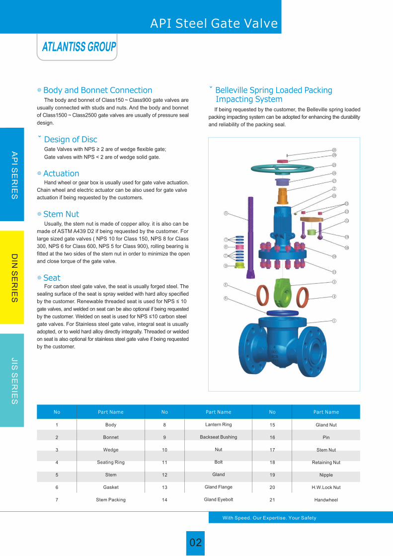
The body and bonnet of Class150~Class900 gate valves are
usually connected with studs and nuts. And the body and bonnet
of Class1500~Class2500 gate valves are usually of pressure seal
design.
◎ Body and Bonnet Connection
Gate Valves with NPS ≥ 2 are of wedge flexible gate;
Gate valves with NPS < 2 are of wedge solid gate.
Design of Disc
Hand wheel or gear box is usually used for gate valve actuation.
Chain wheel and electric actuator can be also used for gate valve
actuation if being requested by the customers.
◎ Actuation
If being requested by the customer, the Belleville spring loaded
packing impacting system can be adopted for enhancing the durability
and reliability of the packing seal.
ˇ Belleville Spring Loaded Packing Impacting System
◎ Seat For carbon steel gate valve, the seat is usually forged steel. The
sealing surface of the seat is spray welded with hard alloy specified
by the customer. Renewable threaded seat is used for NPS ≤ 10
gate valves, and welded on seat can be also optional if being requested
by the customer. Welded on seat is used for NPS ≤10 carbon steel
gate valves. For Stainless steel gate valve, integral seat is usually
adopted, or to weld hard alloy directly integrally. Threaded or welded
on seat is also optional for stainless steel gate valve if being requested
by the customer.
Usually, the stem nut is made of copper alloy. it is also can be made of ASTM A439 D2 if being requested by the customer. For
large sized gate valves ( NPS 10 for Class 150, NPS 8 for Class
300, NPS 6 for Class 600, NPS 5 for Class 900), rolling bearing is
fitted at the two sides of the stem nut in order to minimize the open
and close torque of the gate valve.
◎ Stem Nut
1
2
3
4
5
6
7
8
9
10
11
12
13
14
15
16
17
18
19
20
21
Gland Nut
Pin
Stem Nut
Retaining Nut
Nipple
H.W.Lock Nut
Handwheel
No Part Name No Part Name No Part Name
Body
Bonnet
Wedge
Seating Ring
Stem
Gasket
Stem Packing
Lantern Ring
Backseat Bushing
Nut
Bolt
Gland
Gland Flange
Gland Eyebolt
02
With Speed. Our Expertise. Your Safety
ATLANTISS GROUP
02

Trimcode
Seatring surface
Wedgeseat surface
Stem & backseatbushing
1
2
3
4
5
6
7
8
9
10
11
12
13
13Cr
18Cr-8Ni
25Cr-20Ni
Hard 13Cr
Stellite
Cu-Ni Alloy
Hard 13Cr
13Cr
Cu-Ni Alloy
18Cr-8Ni-Mo
Cu-Ni Alloy
18Cr-8Ni-Mo
19Cr-29Ni
13Cr
18Cr-8Ni
25Cr-20Ni
Hard 13Cr
Stellite
13Cr
13Cr
Stellite
Cu-Ni Alloy
18Cr-8Ni-Mo
Cu-Ni Alloy
Stellite
19Cr-29Ni
A182 F6a
A182 F304
A182 F310
A182 F6a
A182 F6a
Monel
A182 F6a
A182 F6a
Monel
A182 F316
Monel
A182 F316
20 Alloy
※ Suitable for H2S service and meet requirement of NACE MR 0175.
Trim material
1
2
3
4
5
6
7
8
9
10
11
12
13
14
15
16
17
18
19
20
21
No Part Name
Body
Bonnet
Wedge
Seating Ring
Stem
Gasket
Stem Packing
Lantern Ring
Backseat Bushing
Nut
Bolt
Gland
Gland Flange
Gland Eyebolt
Gland Nut
Pin
Stem Nut
Retaining Nut
Nipple
H.W.Lock Nut
Handwheel
A216 WCB
A216 WCB
A216 WCB
A105N
A182 F6a
A182 F6a
A182 F6a
A194 2H
A193 B7
F6a
A216 WCB
A352 LCB
A352 LCB
A352 LCB
A350LF2
A182 F304
A182 F304
A182 F304
A194 4
A320 L7
A182 F304
A352 LCB
A351 CF8
A351 CF8
A351 CF8
A351 CF8
A182 F304
A182 F304
A182 F304
A182 F304
A351 CF8
A351 CF8M
A351 CF8M
A351 CF8M
A351 CF8M
A182 F316
A182 F316
A182 F316
A182 F316
A351 CF8
A351 CF3
A351 CF3
A351 CF3
A351 CF3
A182 F304L
A182 F304L
A182 F304L
A182 F304L
A351 CF8
A193 B8
A194 8
A182 F304
A194 8
A193 B8
A193 B7
A194 2H
ANSI 1045
A351 CF3M
A351 CF3M
A351 CF3M
A351 CF3M
A182 F316L
A182 F316L
A182 F316L
A182 F316L
A351 CF8
A217 WC6
A217 WC6
A217 WC6
A182 F11
A217 WC6
A217 WC9
A217 WC9
A217 WC9
A182 F22
A182 F304
A182 F304
A182 F304
A194 7
A193 B16
A182 F304
217 WC9
A193 B16
A194 7
ANSI 1045
A217 C5
A217 C5
A217 C5
A182 F5
A217 C5
A439 D2 / B148 952A
ANSI 1020
Copper Alloy
ANSI 1020
A197
ASTM Material list of API600 Rising Stem Cast Steel Gate Valve
Graphite+SS304, PTFE
Flexible Graphite
Carbon Steel to ASTM Stainless Steel to ASTM Alloy Steel to ASTM
With Speed. Our Expertise. Your Safety
AP
I SE
RIE
SD
IN S
ER
IES
JIS
SE
RIE
S
API Steel Gate Valve
03
ATLANTISS GROUP

Pressure ratings:Class150
Hydraulic Shell test:3.2MPa
Hydraulic Seat test:2.2MPa
Air test:0.6MPa
Bolted bonnet
Fexible or solid wedge
Renewable seat
(Threaded or welded seat ring)
≤8" Yoke integral with bonnet
≥10" Spearete yoke bolted to bonnet
◎ Construction feature
◎API598 Pressure Test
API Steel Gate Valve
Class
Size
RFDNNPS
L
RTJ BWd H H1 W W1 Hand wheel
Dimensions (mm)
50
65
80
100
125
150
200
250
300
350
400
450
500
600
700
750
800
900
1000
1050
1200
2
12 /2
3
4
5
6
8
10
12
14
16
18
20
24
28
30
32
36
40
42
48
178
190
203
229
254
267
292
330
356
381
406
432
457
508
610
610
660
711
762
787
864
191
203
216
241
267
279
305
343
368
394
419
445
470
521
623
623
673
724
-
-
-
216
241
283
305
381
403
419
457
502
572
610
660
711
813
914
914
965
1016
1066
1092
1168
51
64
76
102
127
152
203
254
305
337
387
438
489
591
684
735
779
874
-
-
-
400
435
515
595
725
780
975
1150
1380
1545
1733
1915
2122
2520
-
-
-
-
-
-
-
-
-
-
-
-
820
1020
1200
1430
1580
1780
1990
2220
2600
3050
3130
3280
3720
4100
4300
5080
200
200
250
280
280
300
350
400
450
500
500
500
600
600
-
-
-
-
-
-
-
-
-
-
-
-
310
310
310
310
310
460
460
460
460
600
600
600
600
-
-
-
19
25
33
49
62
77
123
188
288
385
500
601
764
1007
-
-
-
-
-
-
-
-
-
-
-
-
104
150
215
315
435
552
653
816
1185
1880
2300
2550
3390
4880
5300
7520
Class
150
Weight (Kg)
Gear box
Main size of outside & weight
With Speed. Our Expertise. Your Safety
AP
I SE
RIE
SD
IN S
ER
IES
JIS
SE
RIE
S
ATLANTISS GROUP
04

Bolted bonnet
Fexible or solid wedge
Renewable seat
(Threaded or welded seat ring)
≤8" Yoke integral with bonnet
≥10" Spearete yoke bolted to bonnet
◎ Construction feature
◎API598 Pressure Test
Pressure ratings:Class300
Hydraulic Shell test:7.8MPa
Hydraulic Seat test:5.7MPa
Air test:0.6MPa
Main size of outside & weight
05
API Steel Gate Valve
Class
Size
RFDNNPS
L
RTJ BWd H H1 W W1 Hand wheel Gear box
Dimensions (mm)
Class
300
216
241
283
305
381
403
419
457
502
762
838
914
991
1143
1346
1397
1524
1727
232
257
298
321
397
419
435
473
518
778
854
930
1010
1165
1372
1422
1553
1756
216
241
283
305
381
403
419
457
502
762
838
914
991
1143
1346
1397
1524
1727
51
64
76
102
127
152
203
254
305
337
387
438
489
584
684
735
779
874
420
446
537
619
722
806
1000
1240
1425
1585
1790
1960
2158
2576
-
-
-
-
-
-
-
650
750
835
1030
1280
1460
1620
1830
2000
2220
2620
3080
3180
3300
3760
200
200
250
280
300
350
400
450
500
600
500
650
750
900
-
-
-
-
-
-
-
310
310
310
310
310
310
460
460
460
460
600
600
600
600
600
25
30
48
73
99
130
208
334
450
704
923
1131
1345
2122
-
-
-
-
-
-
-
100
126
186
235
386
502
756
965
1224
1400
2385
3300
3550
4400
6050
50
65
80
100
125
150
200
250
300
350
400
450
500
600
700
750
800
900
2
12 /2
3
4
5
6
8
10
12
14
16
18
20
24
28
30
32
36
Weight(Kg)
With Speed. Our Expertise. Your Safety
AP
I SE
RIE
SD
IN S
ER
IES
JIS
SE
RIE
S
ATLANTISS GROUP
05

Main size of outside & weight
LL
RFDNNPS
RTJ BWd H H1 W W1
Class
600
Class
Size
LHand wheel
Dimensions (mm)
50
65
80
100
125
150
200
250
300
350
400
450
500
600
50
65
80
100
125
150
200
250
300
350
400
292
330
356
432
508
559
660
787
838
889
991
1092
1194
1397
368
419
381
457
559
610
737
838
965
1029
1130
292
330
356
432
508
559
660
787
838
889
991
1092
1194
1397
368
419
381
457
559
610
737
838
965
1029
1130
51
64
76
102
127
152
200
248
298
327
375
419
464
559
47
57
73
98
121
146
190
234
282
311
354
Class
900
-
-
585
695
790
900
1110
1300
1650
1750
1900
2020
2172
2650
-
-
660
750
900
1060
1140
1370
1560
1950
2100
200
250
280
300
350
450
500
650
700
900
900
-
-
-
280
280
300
350
400
500
650
700
900
900
900
-
-
310
310
310
310
310
460
460
460
460
600
600
600
-
-
310
310
310
460
460
460
460
600
600
32
52
60
107
175
216
399
605
851
1177
1513
-
-
-
70
110
140
200
258
358
550
1000
1215
1600
2150
-
-
87
134
227
268
451
657
893
1232
1568
1980
2460
3650
-
-
167
227
285
410
600
1100
1310
1700
2330
444
500
558
665
760
868
1073
1263
1600
1705
1835
-
-
-
500
550
610
702
850
980
1100
1320
1500
1900
2050
295
333
359
435
511
562
664
791
841
892
994
1095
1200
1407
371
422
384
460
562
613
740
841
968
1038
1140
2
12 /2
3
4
5
6
8
10
12
14
16
18
20
24
2
12 /2
3
4
5
6
8
10
12
14
16
Weight(Kg)
Gear box
Pressure ratings:Class900
Hydraulic Shell test:23.3MPa
Hydraulic Seat test:17.1MPa
Air test:0.6MPa
Pressure ratings:Class600
Hydraulic Shell test:15.6MPa
Hydraulic Seat test:11.4MPa
Air test:0.6MPa
Bolted bonnet
Fexible or solid wedge
Renewable seat
(Threaded or welded seat ring)
≤6" Yoke integral with bonnet
≥8" Spearete yoke bolted to bonnet
◎ Construction feature
◎API598 Pressure Test
06
API Steel Gate Valve
With Speed. Our Expertise. Your Safety
AP
I SE
RIE
SD
IN S
ER
IES
JIS
SE
RIE
S
ATLANTISS GROUP
06

Main size of outside & weight
L
d
L
Class
1500
Class
2500
50
65
80
100
125
150
200
250
300
350
400
50
65
80
100
125
150
200
250
300
2
12 /2
3
4
5
6
8
10
12
14
16
2
12 /2
3
4
5
6
8
10
12
368
419
470
546
673
705
832
991
1130
1257
1384
451
508
578
673
794
914
1022
1270
1422
371
422
473
549
676
711
841
1000
1146
1276
1407
454
514
584
683
807
927
1038
1292
1445
368
419
470
546
673
705
832
991
1130
1257
1384
451
508
578
673
794
914
1022
1270
1422
47
57
70
92
111
136
174
222
263
289
330
35
47
57
73
92
111
146
184
219
510
560
620
728
870
1000
1130
1360
-
-
-
530
580
650
750
900
1040
1150
1400
-
-
-
670
770
920
1070
1180
1410
1620
2020
2180
580
630
700
800
960
1100
1200
1460
1660
280
300
350
400
450
500
750
900
-
-
-
280
300
350
400
500
600
750
900
-
-
-
310
310
310
460
460
600
600
600
600
310
310
310
310
460
460
460
600
600
70
110
175
270
378
520
820
1560
-
-
-
100
150
245
390
550
780
1260
2380
-
-
-
202
300
405
575
915
1750
2120
2600
3450
130
180
275
420
580
835
1355
2565
3250
Class
Size
RFDNNPS
L
RTJ BWd H H1 W W1 Hand wheel
Dimensions (mm) Weight(Kg)
Gear box
Pressure ratings:Class1500
Hydraulic Shell test:38.8MPa
Hydraulic Seat test:28.5MPa
Air test:0.6MPa
Bolted bonnet
Fexible or solid wedge
Renewable seat
(Threaded or welded seat ring)
≤6" Yoke integral with bonnet
≥8" Spearete yoke bolted to bonnet
◎ Construction feature
◎API598 Pressure Test
07
API Steel Gate Valve
With Speed. Our Expertise. Your Safety
AP
I SE
RIE
SD
IN S
ER
IES
JIS
SE
RIE
S
ATLANTISS GROUP
07

If being requested by the customer, the Belleville spring loaded
packing impacting can be adopted for enhancing the durability and
reliability of the packing seal.
◎ Belleville Spring Loaded Packing Impacting System
◎ Standards
Design and Manufacture: Cast steel globe valve to BS 1873
and ASME B16.34;Forged steel globe valve to API 602.
Inspection and Test: API 598.
End flange dimension: ASME B16.5.
BW end dimension: ASME B16.25.
Socket-weld dimension: ASME B16.11.
Face to face and end to end: ASME B16.10.
Pressure-temperature ratings: ASME B16.34.
Molded flexible graphite is used for packing material. PTFE or
combined packing material can be also used if being requested by
the customer. The internal surface of the stuffing box, of which area
is contacted with the packing, is of excellent finish (Ra 3.2μm). The
stem surface, contacting with the packing, should be rolled and
pressed after being precisely machined, so as to reach to the high
finish and com-pactness (Ra 0.8μm) and ensure the reliable
tightness of the stem area.
◎ Packing Seal
◎ Actuation
Hand wheel, impact hand wheel & gear box is usually used
for globe valve actuation. Chain wheel and electric actuator can be also
used for globe valve actuation if being requested by the customers.
◎ Body and Bonnet Connection
The body and bonnet of Class150~Class900 globe valves
are usually with studs and nuts. And the body and bonnet of
Class1500~Class2500 globe valves are usually of pressure seal
design.
◎ The features of globe valve
Bolted Bonnet; Outside Screw and Yoke; Rising stems; Metallic
seating surfaces.
◎ Gasket of Cover Flange
Stainless steel + flexible graphite wounded gasket is used for
Class150 and Class300 globe valve. Stainless steel + flexible
graphite wounded gasket is used for Class 600, and ring joint
gasket is also optional for Class600. Ring joint gasket is used
for Class900 globe valve. Pressurized seal design is used for
Class 1500~Class2500 globe valve.
Steel Globe Valve
08
With Speed. Our Expertise. Your Safety
API Steel Globe Valve
AP
I SE
RIE
SD
IN S
ER
IES
JIS
SE
RIE
S
ATLANTISS VALVE
ATLANTISS GROUP
08
1
2
3
4
5
6
7
8
9
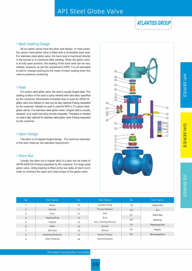
No Part Name No Part Name No Part Name
10
11
12
13
14
15
16
17
18
19
20
21
22
23
24
25
Body
Bonnet
Disc
Seating Ring
Gasket
Stem
Disc Nut
Backseat Bushing
Stem Packing
Gland Nut
Pin
Stem Nut
Bearing
Retaining Nut
Nipple
Bevel gearbox
Lantern Ring
Thrust Washer
Nut
Bolt
Anti-rotating Device
Screw
Gland
Gland Flange
Gland Eyebolt
◎ Stem Design
The stem is of integral forged design. The minimum diameter
of the stem shall per the standard requirement.
All our globe valves have the back seat design. In most cases,
the carbon steel globe valve is fitted with a renewable back seat.
For stainless steel globe valve, the back seat is machined directly
in the bonnet or is machined after welding. When the globe valve
is at fully open position, the sealing of the back seat can be very
reliable. However, as per the requirement of API, it is not advisable
to add or change packing by the mean of back seating when the
valve is pressure containing.
◎ Back Seating Design
◎ Seat
For carbon steel globe valve, the seat is usually forged steel. The
sealing surface of the seat is spray welded with hard alloy specified
by the customer. Renewable threaded seat is used for NPS≤10
globe valve and welded on seat can be also optional if being requested
by the customer. Welded on seat is used for NPS ≥ 12 carbon steel
globe valves. For stainless steel globe valve, integral seat is usually
adopted, or to weld hard alloy directly integrally. Threaded or welded
on seat is also optional for stainless steel globe valve if being requested
by the customer.
◎ Stem Nut
Usually, the stem nut is copper alloy. It is also can be made of
ASTM A439 D2 if being requested by the customer. For large sized
globe valve, rolling bearing is fitted at the two sides of stem nut in
order to minimize the open and close torque of the globe valve.
API Steel Globe Valve
09
With Speed. Our Expertise. Your Safety
AP
I SE
RIE
SD
IN S
ER
IES
JIS
SE
RIE
S
ATLANTISS GROUP
09

Trimcode
Seatring surface
Wedgeseat surface
Stem & backseatbushing
1
2
3
4
5
6
7
8
9
10
11
12
13
13Cr
18Cr-8Ni
25Cr-20Ni
Hard 13Cr
Stellite
Cu-Ni Alloy
Hard 13Cr
13Cr
Cu-Ni Alloy
18Cr-8Ni-Mo
Cu-Ni Alloy
18Cr-8Ni-Mo
19Cr-29Ni
13Cr
18Cr-8Ni
25Cr-20Ni
Hard 13Cr
Stellite
13Cr
13Cr
Stellite
Cu-Ni Alloy
18Cr-8Ni-Mo
Cu-Ni Alloy
Stellite
19Cr-29Ni
A182 F6a
A182 F304
A182 F310
A182 F6a
A182 F6a
Monel
A182 F6a
A182 F6a
Monel
A182 F316
Monel
A182 F316
20 Alloy
Trim material
ASTM Material list of BS1873 Cast Steel Globe Valve
No Part Name Carbon Steel to ASTM Stainless Steel to ASTM Alloy Steel to ASTM
1
2
3
4
5
6
7
8
9
10
11
12
13
14
15
16
17
18
19
20
21
22
23
24
25
A216 WCB
A216 WCB
A216 WCB
A105N
A182 F6a
A182 F6a
A182 F6a
A182 F6a
A182 F6a
A194 2H
A193 B7
F6a
A216 WCB
A352 LCB
A352 LCB
A352 LCB
A350LF2
A182 F304
A182 F304
A182 F304
A182 F304
A182 F304
A194 4
A320 L7
A182 F304
A352 LCB
A351 CF8
A351 CF8
A351 CF8
A351 CF8
A182 F304
A182 F304
A182 F304
A182 F304
A182 F304
A182 F304
A351 CF8
A351 CF8M
A351 CF8M
A351 CF8M
A351 CF8M
A182 F316
A182 F316
A182 F316
A182 F316
A182 F316
A182 F316
A351 CF8
A351 CF3
A351 CF3
A351 CF3
A351 CF3
A182 F304L
A182 F304L
A182 F304L
A182 F304L
A182 F304L
A351 CF3M
A351 CF3M
A351 CF3M
A351 CF3M
A182 F316L
A182 F316L
A182 F316L
A182 F316L
A182 F316L
A182 F316L
A351 CF8
A217 WC6
A217 WC6
A217 WC6
A182 F11
A217 WC6
A217 WC9
A217 WC9
A217 WC9
A182 F22
A182 F304
A182 F304
A182 F304
A182 F304
A182 F304
A194 7
A193 B16
ANSI 1020
A194 2H
A182 F304
A217 WC9
A193 B16
A194 7
ANSI 1045
A217 C5
A217 C5
A217 C5
A182 F5
A217 C5
Graphite+SS304, PTFE
Body
Bonnet
Disc
Seating Ring
Gasket
Stem
Disc Nut
Backseat Bushing
Stem Packing
Lantern Ring
Thrust Washer
Nut
Bolt
Anti-rotating Device
Gland
Screw
Gland Flange
Gland Eyebolt
Gland Nut
Pin
Stem Nut
Bearing
Retaining Nut
Nipple
Bevel gearbox
Flexible Graphite
A193 B7
A194 2H
ANSI 1045
ANSI 1020
A194 2H
A194 8
A193 B8
A182 F304
A194 8
A193 B8
A194 8
A182 F304
A439 D2/ B148 952A
/
ANSI 1020
Copper Alloy
/
A182 F304L
A351 CF8
10
With Speed. Our Expertise. Your Safety
API Steel Globe Valve
AP
I SE
RIE
SD
IN S
ER
IES
JIS
SE
RIE
S
ATLANTISS GROUP
10

Class
Size
RF
DNNPS
L
RTJ BW
d H H1 W W1
H.W G.O
Dimensions (mm)
50
65
80
100
125
150
200
250
300
350
400
500
600
Class
150
203
216
241
292
356
406
495
622
698
787
914
978
1295
216
229
254
305
369
419
508
635
711
800
927
991
1308
203
216
241
292
356
406
495
622
698
787
914
978
1295
51
64
76
102
127
152
203
254
305
337
387
488
590
330
360
390
445
480
520
600
773
880
950
996
-
-
-
-
-
-
-
556
658
805
955
1100
1175
1450
1690
200
250
280
300
350
350
400
450
500
600
600
-
-
-
-
-
-
-
310
310
460
460
460
460
600
600
19
27
36
53
75
94
148
242
438
-
-
-
-
-
-
-
-
-
126
180
291
480
600
850
1650
2200
Weight (Kg)
2
12 /2
3
4
5
6
8
10
12
14
16
20
24
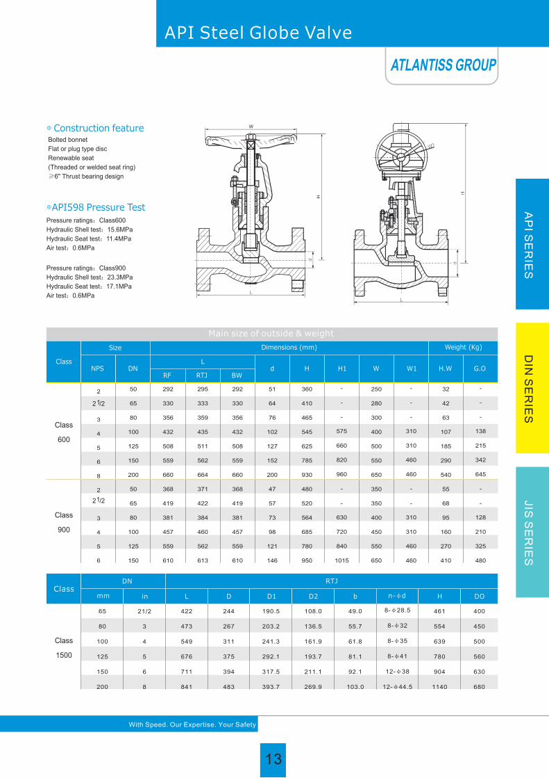
Bolted bonnet
Flat or plug type disc
Renewable seat
(Threaded or welded seat ring)
≥10" Thrust bearing design
Pressure ratings:Class150
Hydraulic Shell test:3.2MPa
Hydraulic Seat test:2.2MPa
Air test:0.6MPa
◎ Construction feature
◎API598 Pressure Test
API Steel Globe Valve
11
With Speed. Our Expertise. Your Safety
AP
I SE
RIE
SD
IN S
ER
IES
JIS
SE
RIE
S
ATLANTISS GROUP
11

Main size of outside & weight
w
L
AP
I SE
RIE
SD
IN S
ER
IES
JIS
SE
RIE
S
Bolted bonnet
Flat or plug type disc
Renewable seat
(Threaded or welded seat ring)
≥10" Thrust bearing design
Pressure ratings:Class300
Hydraulic Shell test:7.8MPa
Hydraulic Seat test:5.7MPa
Air test:0.6MPa
◎ Construction feature
◎API598 Pressure Test
Class
Size
RF
DNNPS
L
RTJ BW
d H H1 W W1
H.W G.O
Dimensions (mm)
Class
300
2
12 /2
3
4
5
6
8
10
12
14
16
18
20
267
292
318
356
400
444
559
622
711
762
864
977
1016
283
308
333
371
416
460
575
638
727
854
879
-
-
267
292
318
356
400
444
559
622
711
762
864
977
1016
51
64
76
102
127
152
203
254
305
337
387
431
482
385
420
440
515
580
660
900
950
1030
1130
1310
-
-
-
-
-
-
-
690
950
990
1080
1155
1325
1473
1574
200
200
280
350
350
400
550
600
700
-
-
-
-
-
-
-
-
-
310
460
460
460
600
600
720
720
25
42
46
74
111
165
275
400
624
-
-
-
-
-
-
-
-
-
195
327
452
725
880
1300
1600
2100
50
65
80
100
125
150
200
250
300
350
400
450
500
Weight (Kg)
12
With Speed. Our Expertise. Your Safety
API Steel Globe Valve
ATLANTISS GROUP
12
Main size of outside & weight
W
AP
I SE
RIE
SD
IN S
ER
IES
JIS
SE
RIE
S
Class
Size
RFDNNPS
L
RTJ BWd H H1 W W1 H.W G.O
Weight (Kg)Dimensions (mm)
Class
600
50
65
80
100
125
150
200
50
65
80
100
125
150
2
3
4
5
6
8
2
3
4
5
6
292
330
356
432
508
559
660
368
419
381
457
559
610
295
333
359
435
511
562
664
371
422
384
460
562
613
292
330
356
432
508
559
660
368
419
381
457
559
610
51
64
76
102
127
152
200
47
57
73
98
121
146
360
410
465
545
625
785
930
480
520
564
685
780
950
-
-
-
575
660
820
960
-
-
630
720
840
1015
250
280
300
400
500
550
650
350
350
400
450
550
650
-
-
-
310
310
460
460
-
-
310
310
460
460
32
42
63
107
185
290
540
55
68
95
160
270
410
-
-
-
138
215
342
645
-
-
128
210
325
480
Class
900
12 /2
12 /2
Bolted bonnet
Flat or plug type disc
Renewable seat
(Threaded or welded seat ring)
≥6" Thrust bearing design
Pressure ratings:Class600
Hydraulic Shell test:15.6MPa
Hydraulic Seat test:11.4MPa
Air test:0.6MPa
◎ Construction feature
◎API598 Pressure Test
API Steel Globe Valve
With Speed. Our Expertise. Your Safety
ClassDN
mm in L D D1 D2 b n-φd H DO
Class
1500
65
80
100
125
150
200
21/2
3
4
5
6
8
422
473
549
676
711
841
244
267
311
375
394
483
190.5
203.2
241.3
292.1
317.5
393.7
108.0
136.5
161.9
193.7
211.1
269.9
49.0
55.7
61.8
81.1
92.1
103.0
8-φ28.5
8-φ32
8-φ35
8-φ41
12-φ38
12-φ44.5
461
554
639
780
904
1140
400
450
500
560
630
680
RTJ
Pressure ratings:Class900
Hydraulic Shell test:23.3MPa
Hydraulic Seat test:17.1MPa
Air test:0.6MPa
ATLANTISS GROUP
13

Bolted Bonnet;
Swing and lift disc;
Metallic seating surfaces.
◎ The features of check valve
Stainless steel + flexible graphite wounded gasket is used for
Class150 and Class300 check valve; Stainless steel + flexible
graphite wounded gasket is used for Class600 check valve, and
joint gasket is also optional for Class600 check valve; Ring joint
gasket is used for Class900 check valve; Pressure seal design is
used for Class1500~Class2500 check valves.
◎ Body-To-Bonnet Joint
For carbon steel check valve, the seat is usually forged Steel.
The sealing surface of the seat is spray welded with hard alloy
Specified by the customer. Renewable threaded seat is used for
NPS≤10 check valves, and welded on seat can be also optional if
being requested by the customer. Welded on seat is used for NPS
≥12 carbon steel check valves. For stainless steel check Valve,
integral seat is usually adopted, or to weld hard alloy directly integrally.
Threaded or welded on seat is also optional for stainless steel check
valve if being requested by the customer.
◎ Seat
◎ Reliable seat seal
Design and Manufacture: Cast steel check valve to BS1868,
ASME B16.34 and API 6D;
Forged steel check valve to API 602.
Inspection and Test: API 598.
End flange dimension: ASME B16.5Јfor NPSЎ24ЈЈ
ASME B 16.47 series B, ASME B16.47 series A,
MSS SP-44Јfor NPSЈ24Ј.
BW end dimension: ASME B16.25.
Socket-weld dimension: ASME B16.11.
Face to face and end to end: ASME B16.10.
Pressure-temperature ratings: ASME B16.34.
◎ Body and Bonnet Connection
The body and bonnet of Class150~Class900 check valves are
usually with studs and nuts. And the body and bonnet of Class1500~
Class2500 check valves are usually of pressure seal design.
Steel Check Valve
14
With Speed. Our Expertise. Your Safety
API Steel Check Valve
AP
I SE
RIE
SD
IN S
ER
IES
JIS
SE
RIE
S
ATLANTISS VALVE
ATLANTISS GROUP
14

1
2
3
4
5
No Part Name No Part Name No Part Name
6
7
8
9
10
11
12
13
14
Body
Cover
Seat Ring
Disc
Hinge
Yoke
Gasket
Disc Washer
Disc Nut
Pin
Nut
Bolt
Screw
Lifting Lug
15
With Speed. Our Expertise. Your Safety
API Steel Check ValveA
PI S
ER
IES
DIN
SE
RIE
SJIS
SE
RIE
S
ATLANTISS GROUP
15

AP
I SE
RIE
SD
IN S
ER
IES
JIS
SE
RIE
S
16
With Speed. Our Expertise. Your Safety
Trim material
Trimcode
Seatring surface
Wedgeseat surface
Hinge Pin
1
2
3
4
5
6
7
8
9
10
11
12
13
13Cr
18Cr-8Ni
25Cr-20Ni
Hard 13Cr
Stellite
Cu-Ni Alloy
Hard 13Cr
13Cr
Cu-Ni Alloy
18Cr-8Ni-Mo
Cu-Ni Alloy
18Cr-8Ni-Mo
19Cr-29Ni
13Cr
18Cr-8Ni
25Cr-20Ni
Hard 13Cr
Stellite
13Cr
13Cr
Stellite
Cu-Ni Alloy
18Cr-8Ni-Mo
Cu-Ni Alloy
Stellite
19Cr-29Ni
A182 F6a
A182 F304
A182 F310
A182 F6a
A182 F6a
Monel
A182 F6a
A182 F6a
Monel
A182 F316
Monel
A182 F316
20 Alloy
1
2
3
4
5
6
7
8
9
10
11
12
13
14
No. Part nameCarbon Steel
to ASTM
A216 WCB
A216 WCB
A105N
A216 WCB
A216 WCB
A216 WCB
A182 F6a
A182 F6a
A182 F6a
A194 2H
A193 B7
193 B7
A352 LCB
A352 LCB
A352 LF2
A352 LCB
A352 LCB
A352 LCB
A182 F6a
A182 F304
A182 F304
A194 4
A320 L7
A320 L7
A351 CF8
A351 CF8
A351 CF8
A351 CF8
A351 CF8
A351 CF8
A182 F304
A182 F304
A182 F304
A182 F304
A351 CF8M
A351 CF8M
A351 CF8M
A351 CF8M
A351 CF8M
A351 CF8M
A182 F316
A182 F316
A182 F316
A182 F316
A351 CF3
A351 CF3
A351 CF3
A351 CF3
A351 CF3
A351 CF3
A182 F304L
A182 F304L
A182 F304L
A182 F304L
A351 CF3M
A351 CF3M
A351 CF3M
A351 CF3M
A351 CF3M
A351 CF3M
A182 F316L
A182 F316L
A182 F316L
A182 F316L
A194 2H
A217 WC6
A217 WC6
A182 F11
A217 WC6
A217 WC6
A217 WC6
A217 WC9
A217 WC9
A182 F22
A217 WC9
A217 WC9
A217 WC9
A182 F304
A182 F304
A182 F304
A194 7
A193 B16
A193 B16
A217 C5
A217 C5
A182 F5
A217 C5
A217 C5
A217 C5
Stainless Steel to ASTM Alloy Steel to ASTM
ASTM Material list of BS1868 Swing Check Valve
Body
Cover
Seat Ring
Disc
Hinge
Yoke
Gasket
Disc Washer
Disc Nut
Pin
Nut
Bolt
Screw
Lifting Lug
※ Suitable for H2S service and meet requirement of NACE MR 0175.
API Steel Check Valve
Graphite+SS304, PTFE
A194 8
A193 B8
ATLANTISS GROUP
16

AP
I SE
RIE
SD
IN S
ER
IES
JIS
SE
RIE
S
17
With Speed. Our Expertise. Your Safety
Bolted cover
Renewable seat
(Threaded or welded seat ring)
Pressure ratings:Class150
Hydraulic Shell test:3.2MPa
Hydraulic Seat test:2.2MPa
Air test:0.6MPa
◎ Construction feature
◎API598 Pressure Test
Main size of outside & weight
Size
DNNPS
L
H
Class 150
RF RTJ BW
d
L
H
Class 300
RF RTJ BW
d
50
65
80
100
125
150
200
250
300
350
400
450
500
600
650
700
750
800
900
2
1/2 2
3
4
5
6
8
10
12
14
16
18
20
24
26
28
30
32
36
203
216
241
292
330
356
495
622
699
787
864
978
978
1295
1295
1448
1524
1727
1956
216
229
254
305
343
368
508
635
711
800
876
991
991
1308
-
-
1537
-
1969
203
216
241
292
330
356
495
622
699
787
864
978
978
1295
1295
1448
1524
1727
1956
51
64
76
102
127
152
203
254
305
337
387
438
489
591
633
684
735
779
874
132
147
176
198
255
320
380
440
480
530
580
618
657
760
840
920
980
1016
1092
15
20
27
45
58
69
131
219
321
380
560
630
770
960
1250
1580
1950
2800
3200
267
292
318
356
400
445
533
622
711
838
864
978
1016
1346
1346
1499
1594
1727
2083
283
308
333
371
416
460
549
638
727
854
879
994
1035
1368
1372
1524
1619
-
-
267
292
318
356
400
445
533
622
711
838
864
978
1016
1346
1346
1499
1594
1727
2083
51
64
76
102
127
152
203
254
305
337
387
432
483
584
633
684
735
779
874
144
169
210
260
295
326
380
440
520
540
588
670
720
850
920
1150
1260
1380
1540
20
35
40
61
80
130
190
296
450
640
850
1030
1330
1950
2300
2600
3200
3700
4300
Weight
(Kg)
Weight
(Kg)
API Steel Swing Check Valve
Pressure ratings:Class300
Hydraulic Shell test:7.8MPa
Hydraulic Seat test:5.7MPa
Air test:0.6MPa
ATLANTISS GROUP
17

Main size of outside & weight
DNNPSL
H
Class 600
RF RTJ BWd
LH
Class 900
RF RTJ BWd
DNNPSL
H
Class 1500
RF RTJ BWd
LH
Class 2500
RF RTJ BWd
50
65
80
100
125
150
200
250
300
350
400
450
500
600
2
3
4
5
6
8
10
12
14
16
18
20
24
292
330
356
432
508
559
660
787
838
889
991
1092
1194
1397
295
333
359
435
511
562
664
791
841
892
994
1095
1200
1407
292
330
356
432
508
559
660
787
838
889
991
1092
1194
1397
51
64
76
102
127
152
200
248
298
327
375
419
464
559
170
178
246
290
320
360
430
502
554
595
680
778
970
1100
28
40
68
117
155
192
340
515
750
890
1303
1800
2150
3200
368
419
381
457
559
610
737
838
965
1029
1130
1219
1321
1549
371
422
384
460
562
613
740
841
968
1038
1140
1232
1334
1568
368
419
381
457
559
610
737
838
965
1029
1130
1219
1321
1549
47
57
73
98
121
146
190
234
282
311
354
400
444
533
200
220
280
320
360
400
480
560
632
680
780
880
1050
1200
48
75
95
135
200
264
424
730
1070
1180
1790
2500
3080
4600
50
65
80
100
125
150
200
250
300
350
400
2
3
4
5
6
8
10
12
14
16
368
419
470
546
673
705
832
991
1130
1257
1384
371
422
473
549
676
711
841
1000
1146
1276
1407
368
419
470
546
673
705
832
991
1130
1257
1384
47
57
70
92
111
136
174
222
263
289
330
210
240
303
340
380
430
500
590
660
710
820
48
75
120
180
294
385
634
1140
1650
2000
2700
451
508
578
673
794
914
1022
1270
1422
-
-
454
514
584
683
807
927
1038
1292
1445
-
-
451
508
578
673
794
914
1022
1270
1422
-
-
35
47
57
73
92
111
146
184
219
-
-
230
260
330
370
410
460
530
620
690
-
-
68
100
165
260
440
580
970
1700
2600
-
-
1/2 2
Weight
(Kg)
Weight
(Kg)
Weight
(Kg)
Weight
(Kg)
Size
Size
Bolted cover
Renewable seat
(Threaded or welded seat ring)
Pressure ratings:Class600
Hydraulic Shell test:15.6MPa
Hydraulic Seat test:11.4MPa
Air test:0.6MPa
1/2 2
◎ Construction feature
◎API598 Pressure Test
With Speed. Our Expertise. Your Safety
API Steel Swing Check Valve
AP
I SE
RIE
SD
IN S
ER
IES
JIS
SE
RIE
S
Pressure ratings:Class900
Hydraulic Shell test:23.3MPa、
Hydraulic Seat test:17.1MPa、
Air test:0.6MPa
Pressure ratings:1500
Hydraulic Shell test:38.8MPa
Hydraulic Seat test:28.5MPa
Air test:0.6MPa
ATLANTISS GROUP
18

19
With Speed. Our Expertise. Your Safety
AP
I SE
RIE
SD
IN S
ER
IES
JIS
SE
RIE
S
API Floating Ball Valve
Design and Manufacture: API 6D, BS5351, ASME B16.34
API 608, MSS-SP-72
Face To Face Dimension: ASME B16.10
Flange Connection Dimension: ASME B16.5
BW Connection Dimension: ASME B16.25
Test And Inspection: API 598
Fire-safe Design: API 607
Anti-static Design&Anti Blow-out Stem
◎ Standards
The structure design of elastic sealing ring has been adopted for
floating ball valves. This seat design features a bigger sealing pressure
ratio between the ring surface and the ball when medium pressure
gets lower, where the contacting area is smaller. Thus, the reliable
seal is ensured. When the medium pressure gets higher, the contacting
area between seat ring and ball becomes bigger as the sealing ring
transforms elastically to undertake the bigger force pushed by the
medium without any damage.
Floating ball valves are suitable for various kinds of pipelines
of Class 150 to Class 600, to turn on or off the pipeline medium,
of which the operation types include manual, worm gear and
pneumatic or electric actuators.
◎ Application
◎ Reliable seat seal
The traditional packing flange design has been improved to be
of two piece structure, i.e., being as a packing flange plate and a
follower, the latter contacts the flange plate with spherical surface.
Thus, the follower remains vertical always, and is lined internally
with a PTFE bush to prevent the galling against and friction between
the stem, which can also reduce the operation torque of the valve.
◎ Anti-static feature
Floating Ball ValveATLANTISS VALVE
ATLANTISS GROUP
19

With Speed. Our Expertise. Your Safety
AP
I SE
RIE
SD
IN S
ER
IES
JIS
SE
RIE
S
V type packing structure has been employed to effectively
transform the pushing force of the gland flange and the medium
pressure into the sealing force against the stem.
With the valve heated in a fire application, the non-metal material
parts such as seat sealing ring of PTFE, stem back seat gasket, gland
packing, and the sealing gasket between body and bonnet might
disintegrate or be damaged due to high temperature. Our company specially
designed structure of auxiliary metal to metal seal is provided to effectively
prevent both internal and external leakage of the valve. As required by
customers, Our company floating ball valves with design can meet
the requirement of API 607.
◎ Fire safe design
The blow-out proof design has been adopted for the stem to
ensure that even if the pressure in the body cavity is risen accidently
and the packing flange becomes invalid, the stem may not be blown
out by medium. The stem features the design with a backseat,
being assembled from underneath. The sealing force against the
backseat gets higher as the medium pressure becomes higher. So
the reliable seal of the stem can be assured under variable medium
pressure.
◎ Reliable stem seal
◎ Wrong operation prevention
To prevent the ball valve from wrong operation, the keylock with
90°of open and close positioning pad has been provided, Which
can be lockable as required. At the stem head, where the lever
fixes, a flat is designed so that the valve opens with the lever in
parallel to piping, and with the lever right-angled to the piping, the
valve is closed. So, it is ensured that the valve indicator of open
and close can never make mistake.
◎ Mounting pad provided
Our company has provided for floating ball valve with a mounting
pad , through which it is easy to fix the actuators, such as worm
gear, pneumatic and electric actuators.
API Floating Ball Valve
ATLANTISS GROUP
20

21
With Speed. Our Expertise. Your Safety
AP
I SE
RIE
SD
IN S
ER
IES
JIS
SE
RIE
S
API Floating Ball Valve
ASTM Material list of floating ball valve
No Part Name Carbon Steel to ASTM Stainless Steel to ASTM
1
2
3
4
5
6
7
8
9
10
11
12
13
14
15
16
17
18
19
20
21
Body
Bonnet
Ball
Stem
Seat ring
Gasket
O-ring
Bolt
Nut
Small spring
Small ball
Thrust washer
Stem packing
Packing gland
Shaft sleeve
Screw
Positioning plate
Rataining ring
Lever
Gasket
Screw
A216 WCB
A216 WCB
A351 CF8
A182 F6a
A193 B7/B7M
A194 2H/2HM
A216 WCB
A193 B7
PTFE, RTFE, PEEK, DELRIN
Graphite+SS304, PTFE
Fluororubber
A352 LCB
A352 LCB
A352 LCB
A182 F304
A193 L7/L7M
A194 4 /4M
A352 LCB
A320 L7
A351 CF8
A351 CF8
A351 CF8
A182 F304
A351 CF8
A351 CF8M
A351 CF8M
A351 CF8M
A182 F316
SS304
SS304
PTFE
Flexible Graphite/PTFE
A351 CF8M
PTFE
Galvanized Steel
Carbon Steel
Carbon Steel
Carbon Steel
Carbon Steel
A351 CF3
A351 CF3
A351 CF3
A182 F304L
A193 B8/B8M
194 8/8M
A351 CF3
A193 B8/B8M
A351 CF3M
A351 CF3M
A351 CF3M
A182 F316L
A351 CF8M
ATLANTISS GROUP
21

Sizein
mm
in
mm
in
mm
in
mm
BW
L/L1
(RF/BW)
L2
(RTJ)
H
WT
(Kg)
RF/RTJ
2
50
11.50
292
11.62
295
4.75
120
19
13
12 /2
65
13.00
330
13.12
333
6.88
174
31
22
3
80
14.00
356
14.12
359
8.38
212
39
27
4
100
17.00
432
17.12
435
9.25
234
71
53
1/2
15
6.50
165
-
-
2.38
61.5
3.3
2.6
3/4
20
7.50
190
-
-
2.38
61.5
4.5
3.1
1
25
8.50
216
-
-
3.00
78
7.2
4.8
11 /2
40
9.50
241
-
-
4.00
101
13.5
8
Sizein
mm
in
mm
in
mm
in
mm
BW
L
(RF)
L1
(BW)
H
WT
(Kg)
RF
2
50
8.50
216
8.50
216
4.12
105
14.5
8.7
12 /2
65
9.50
241
9.50
241
6.12
153
23.5
15
3
80
11.12
283
11.12
283
7.25
187
30
18
4
100
12.00
305
12.00
305
8.00
206
55
36
6
150
15.88
403
18.00
457
10.00
255
118
85
8
200
19.75
502
20.50
521
11.00
280
200
152
10
250
22.38
568
22.00
559
13.50
345
250
182
12
300
25.50
648
25.00
635
16.50
420
330
232
1/2
15
5.50
140
5.50
140
2.12
55
2.5
1.8
3/4
20
6.00
152
6.00
152
2.12
55
3.5
2
1
25
6.50
165
6.50
165
2.75
70
5.5
3.2
11 /2
40
7.50
190
7.50
190
3.50
90
10.5
5.5
AP
I SE
RIE
SD
IN S
ER
IES
JIS
SE
RIE
S
22
With Speed. Our Expertise. Your Safety
API Floating Ball Valve
Sizein
mm
in
mm
in
mm
in
mm
BW
L
(RF)
L1
(BW)
H
WT
(Kg)
RF
2
50
7.00
178
8.50
216
4.12
105
9.5
8.5
12 /2
65
7.50
190
9.50
241
6.12
155
15
14
3
80
8.00
203
11.12
283
7.25
185
19
21
4
100
9.00
229
12.00
305
8.00
205
33
35
6
150
15.50
394
18.00
457
10.00
255
93
98
8
200
18.00
457
20.50
521
11.00
280
160
170
10
250
21.00
533
22.00
559
13.50
345
200
225
12
300
24.00
610
25.00
635
16.50
420
280
295
1/2
15
4.25
108
5.50
140
2.12
55
2.3
1.8
3/4
20
4.62
117
6.00
152
2.12
55
3
2.8
1
25
5.00
127
6.50
165
2.75
70
4.5
3.7
11 /2
40
6.50
165
7.50
190
3.50
90
7
6.2
600Lb
300Lb
150Lb Main size of outside & weight
Main size of outside & weight
Main size of outside & weight
ATLANTISS GROUP
22

AP
I SE
RIE
SD
IN S
ER
IES
JIS
SE
RIE
S
23
With Speed. Our Expertise. Your Safety
API Trunnion Ball Valve
Design and Manufacture: API 6D, BS5351, ASME B16.34
API 608, MSS-SP-72
Face To Face Dimension: ASME B16.10
End flange dimension: ASME B16.5(for NPS�24); ASME B16.47
series B, ASME B16.47 series A, MSS SP-44(for NPS�24).
BW Connection Dimension: ASME B16.25
Test And Inspection: API 598
Fire-safe Design: API 607
Anti-static Design & Anti Blow-out Stem
◎ Standards
According to customers' requirement, the trunnion ball valves
made by Our company are provided with devices for urgent
grease injection, which are on both the stem and seat for the trunnion
ball valves of DN>150mm (NPS6), and in the body cavity for the
valve of DN<125mm. When the O ring of stem or the body seat ring
is damaged due to accident, the medium leakage between body
and stem can be prevented by injecting the sealing grease through
◎ Urgent grease injection device
Atlantiss Marine’s Valve trunnion ball valve features the front
ball sealing design structure. Each seat of the ball valve can
separately cut off the medium at both inlet and outlet of the
valve to realize double-block functions. When the ball valve
is closed, body cavity and two of the body ends can be blocked
with each other even if both the inlet and outlet are under
pressure, when the medium left in the body cavity might be
bled through the relief valve.
◎ Double-block and bleed functions
Blow-out proof structure is provided with for the stem, which is
positioned by the up-end cap and screw, being guaranteed not
to be blown-out by the medium even if at abnormal risen
pressure in the cavity.
◎ Blow-out proof stem
Trunnion Ball ValveATLANTISS VALVE
ATLANTISS GROUP
23

Our company has provided for trunnion ball valve with a mounting
pad for fixing the actuators, such as worm gear, pneumatic, electric,
hydraulic, and pneumatic & hydraulic acturtors.
Graphite sealing ring
Fire safe design of valve
body and bonnet flangesFire safe design of stem
Fire safe design of seat
With the valve heated in a fire application, the non-metal
material parts such as seat sealing ring of PTFE, O ring for the
stem, and sealing gasket for body and bonnet, might be damaged
due to high temperature. Our company special design of auxiliary
metal to metal or the graphite seal is provited for the trunnion ball
valve to effectively prevent both internal and external leakage of
the valve. As required by customers, Our company fire safe
design for the trunnion ball valve meets the requirement of
API 607, API 6Fa, BS 6755.
◎ Fire safe design
According to some special working conditions and customers'
requirement, We has provided the trunnion ball valve with the
Bi-sealing design structure, i.e. seat sealing in front of the ball and
seat sealing behind the ball, thus the reliable sealing of the valve is
ensured because the valve can perform normally even if one of
the effective sealing designs becomes lost due to the abnormal
condition.
Regarding the seat in front of the ball, the piston effect formed
by the area difference between D1 and D2 ,plus the pre-tightened
force of a spring would cause the seat in front of the ball by the
pressure difference of the medium before and after the valve to
touch the ball closely to form the tightness, of which the sealing
force will become bigger as the pressure difference gets higher.
Regarding the seat after the ball, the piston effect formed by the
area difference between D2 and D3 ,plus the pretig-htened force of
a spring would cause the seat behind the ball to touch the ball closely
to form the tightness, of which the sealing force will become bigger
as the pressure difference gets higher.
◎ The Bi-sealing design structure, i.e. seat sealing
in front of the ball and seat sealing behind the ball
The ball of the trunnion ball valve gets close contact with each
other through the trunnion, adjusting cushion, and down-end cap,
the passage of static electricity thus forms together with the valve,
which may lead the static electricity caused by sparks generated
by friction between the ball and seat during on and off performance
to the ground to prevent the possible risk of fire or explosion.
◎ Anti-static design
◎ Mounting pad provided
As the liquid medium left in the body cavity gasifies due to
increased temperature, the pressure in the body cavity becomes
abnormally higher when the medium itself in the cavity would
propel the seat and self-relieves the pressure to ensure the safety
of valve.
◎ Self-relief in the body cavity
24
With Speed. Our Expertise. Your Safety
API Trunnion Ball Valve
AP
I SE
RIE
SD
IN S
ER
IES
JIS
SE
RIE
S
ATLANTISS GROUP
24

25
With Speed. Our Expertise. Your Safety
AP
I SE
RIE
SD
IN S
ER
IES
JIS
SE
RIE
S
Main size of outside & weight
Main size of outside & weight
300Lb
Sizein
mm
in
mm
in
mm
in
mm
in
mm
BW
L
(RF)
L1
(BW)
H
W
WT
(Kg)
RF
2
50
8.50
216
8.50
216
7.00
177
14
350
19
14
12 /2
65
9.50
241
9.50
241
7.50
190
16
400
24
16
3
80
11.12
283
11.12
283
8.25
210
20
500
34
25
4
100
12.00
305
12.00
305
9.25
235
20
500
48
34
6
150
15.88
403
18.00
403
20.88
530
24
600
101
82
8
200
19.75
502
20.50
521
24.62
625
24
600
175
145
10
250
22.38
568
22.00
559
25.62
650
24
600
200
155
12
300
25.50
648
25.00
635
30.75
780
24
600
255
185
14
350
30.00
762
30.00
762
31.00
790
32
800
325
238
16
400
33.00
838
33.00
838
36.25
920
32
800
485
375
18
450
36.00
914
36.00
914
38.25
970
32
800
635
516
20
500
39.00
991
39.00
991
43.38
1100
32
800
935
782
24
600
45.00
1143
45.00
1143
45.25
1150
32
800
1500
1280
26
650
49.00
1245
49.00
1245
50.75
1290
32
800
1750
1375
28
700
53.00
1346
53.00
1346
55.12
1400
32
800
2225
1825
30
750
55.00
1397
55.00
1397
64.12
1630
32
800
2450
2180
32
800
60.00
1524
60.00
1524
70.88
1800
32
800
2870
2260
36
900
-
-
-
-
-
-
-
-
-
-
150Lb
Sizein
mm
in
mm
in
mm
in
mm
in
mm
BW
L
(RF)
L1
(BW)
H
W
WT
(Kg)
RF
2
50
7.00
178
8.50
216
7.00
177
14
350
15
13.5
12 /2
65
7.50
190
9.50
241
7.50
190
16
400
19
15.5
3
80
8.00
203
11.12
283
8.25
210
20
500
27
24.5
4
100
9.00
229
12.00
305
9.25
235
20
500
38
32.5
6
150
15.50
394
18.00
457
20.88
530
24
600
81
76
8
200
18.00
457
20.50
521
24.62
625
24
600
140
132
10
250
21.00
533
22.00
559
25.62
650
24
600
160
147
12
300
24.00
610
25.00
635
30.75
780
24
600
205
182
14
350
27.00
686
30.00
762
31.00
790
32
800
260
241
16
400
30.00
762
33.00
838
36.25
920
32
800
390
370
18
450
34.00
864
36.00
914
38.25
970
32
800
510
495
20
500
36.00
914
39.00
991
43.38
1100
32
800
750
726
24
600
42.00
1067
45.00
1143
5.25
1150
32
800
1200
1125
26
650
45.00
1143
49.00
1245
50.75
1290
32
800
1400
1250
28
700
49.00
1245
53.00
1346
55.12
1400
32
800
1860
1640
30
750
51.00
1295
55.00
1397
64.12
1630
32
800
2100
1930
32
800
54.00
1372
60.00
1524
70.88
1840
32
800
2530
2390
36
900
60.00
1524
68.00
1727
80.75
2050
32
800
2970
2760
300Lb
API Cast Steel Trunnion Ball Valve
ATLANTISS GROUP
25

Main size of outside & weight
Main size of outside & weight
Main size of outside & weight
in
mm
in
mm
in
mm
in
mm
in
mm
BW
RF/RTJ
in
mm
in
mm
in
mm
in
mm
in
mm
BW
RF/RTJ
1500Lb
2
50
14.50
368
14.62
371
11.25
285
20
500
49
33
12 /2
65
16.50
419
16.62
422
12.00
306
20
500
67
44
3
80
18.50
470
18.62
473
13.25
338
24
600
106
73
4
100
21.50
546
21.62
549
20.00
506
24
600
153
87
6
150
27.75
705
28.00
711
33.50
852
24
600
268
145
8
200
32.75
832
33.12
841
39.38
1000
32
800
540
345
10
250
39.00
991
39.38
1000
41.12
1045
32
800
1020
685
12
300
44.50
1130
45.12
1146
49.38
1255
32
800
1475
1050
14
350
49.50
1257
50.25
1276
50.00
1270
32
800
1885
1385
16
400
54.50
1384
55.38
1407
58.50
1485
32
800
2455
1735
Sizein
mm
in
mm
in
mm
in
mm
in
mm
BW
L/L1
(RF/BW)
L2
(RTJ)
H
W
WT
(Kg)
RF/RTJ
2
50
11.50
292
11.62
295
7.12
180
14
350
26
19
12 /2
65
13.00
330
13.12
333
7.62
193
16
400
35
25
3
80
14.00
356
14.12
359
8.50
215
20
500
58
42
4
100
17.00
432
17.12
435
9.50
241
20
500
81
51
6
150
22.00
559
22.12
562
21.52
540
24
600
142
82
8
200
26.00
660
26.12
664
25.00
635
24
600
287
200
10
250
31.00
787
31.12
791
26.12
665
24
600
540
395
12
300
33.00
838
33.12
841
31.12
790
24
600
780
610
14
350
35.00
889
35.12
892
31.88
810
32
800
1000
805
16
400
39.00
991
39.12
994
36.38
925
32
800
1300
1010
18
450
43.00
1092
43.12
1095
38.75
985
32
800
1700
1350
20
500
47.00
1194
47.25
1200
44.50
1130
32
800
2100
1656
24
600
55.00
1397
55.38
1407
46.62
1185
32
800
3400
2775
26
650
57.00
1448
57.50
1461
52.50
1335
32
800
3800
3125
28
700
61.00
1549
61.50
1562
57.00
1450
32
800
4500
3790
600Lb
Size
L/L1
(RF/BW)
L2
(RTJ)
H
W
WT
(Kg)
2
50
14.50
368
14.62
371
8.62
219
20
500
31
23
12 /2
65
16.50
419
16.62
422
9.25
235
20
500
43
31
3
80
15.00
381
15.12
384
10.25
260
20
500
68
51
4
100
18.00
457
18.12
460
15.38
390
24
600
98
61
6
150
24.00
610
24.12
613
25.75
655
24
600
171
102
8
200
29.00
737
29.12
740
30.25
770
24
600
345
240
10
250
33.00
838
33.12
841
31.75
805
24
600
650
480
12
300
38.00
965
38.12
968
38.00
965
32
800
940
735
14
350
40.50
1029
40.88
1038
38.50
980
32
800
1205
965
16
400
44.50
1130
44.88
1140
45.00
1145
32
800
1565
1215
18
450
48.00
1219
48.50
1232
47.00
1195
32
800
2050
1625
20
500
52.00
1321
52.50
1334
53.50
1360
32
800
2535
1995
24
600
61.00
1549
61.75
1568
56.00
1425
32
800
3950
3335
900Lb
Size
L/L1
(RF/BW)
L2
(RTJ)
H
W
WT
(Kg)
900Lb
1500Lb
26
With Speed. Our Expertise. Your Safety
AP
I SE
RIE
SD
IN S
ER
IES
JIS
SE
RIE
S
API Cast Steel Trunnion Ball Valve
ATLANTISS GROUP
26

27
With Speed. Our Expertise. Your Safety
AP
I SE
RIE
SD
IN S
ER
IES
JIS
SE
RIE
S
ASTM Material list of cast steel trunnion mounted ball valve
1
2
3
4
5
6
7
8
9
10
11
12
13
14
15
16
17
18
19
20
21
22
23
24
25
26
27
28
29
30
31
32
A182 F316
A182 F3316
A351 CF8M
A182 F316
SS304 +Graphite, PDFE
A182 F316
A182 F316
PTFE, RTFE, PEEK, DELRIN
A182 F316
Fluororubber
Flexible Graphite
A182 F316
INCONEL X-750
PTFE
Cabon Steel
PTFE
PTFE Flexible Graphite
PTFE
A182 F316
PTFE
A182 F316
Carbon Steel
Carbon Steel
A182 F316
A182 F316
A182 F316
A182 F316
Carbon Steel
Carbon Steel
A182 F304L
A182 F304L
A351 CF3
A182 F304L
A182 F304L
A182 F304L
A182 F304L
A182 F304L
A193 B8/B8M
A194 8/8M
A193 B8/B8M
A182 F304L
A182 F304L
A182 F304L
A182 F304L
A182 F304L
A182 F304L
※ Suitable for H2S service and meet requirement of NACE MR 0175.
No Part Name
Body
Bonnet
Ball
Stem
Gasket
Seat
Clamping ring
Seat ring
Seat back
O-ring
Seat gasket
Stuffing box
Bolt
Nut
Spring
Screw
Gasket
Flat key
Shaft sleeve
Stem packing
Thrust washer
Packing gland
Shaft sleeve
Support plate
Yoke
Pin
Small check valve
Grease injector
Vent plug
Drain plug
Lifting lug
Support feet
ASTM A105N
ASTM A105N
A351 CF8
A182 F6a
A105N+ENP
A105N+ENP
A105N+ENP
A105N+ENP
A193 B7/B7M
A194 2H/2HM
A193 B7
ASTM A105N
ASTM A105N
ASTM A105N
Garbon steel
Garbon steel
Garbon steel
A350 LF2
A350 LF2
A351 CF8
A182 F304
LF2+ENP
LF2+ENP
LF2+ENP
LF2+ENP
A320 L7/L7M
A194 4/4M
A320 L7
A350 LF2
A350 LF2
A350 LF2
Garbon steel
Garbon steel
Garbon steel
A182 F304
A182 F304
A351 CF8
A182 F304
A182 F304
A182 F304
A182 F304
A182 F304
A182 F304
A182 F304
A182 F304
A182 F304
A182 F304
A182 F304
A182 F316L
A182 F316L
A351 CF3M
A182 F316L
A182 F316L
A182 F316L
A182 F316L
A182 F316L
A182 F316L
A182 F316L
A182 F316L
A182 F316L
A182 F316L
A182 F316L
A182 F51
A182 F51
CD4MCU
A182 F51
A182 F51
A182 F51
A182 F51
A182 F51
A182 F51
A182 F51
A182 F51
A182 F51
A182 F51
A182 F51
Carbon Steel to ASTM Stainless Steel to ASTM
API Forged Steel Trunnion ball valve
ATLANTISS GROUP
27

Main size of outside & weight
Main size of outside & weight
Sizein
mm
in
mm
in
mm
in
mm
in
mm
BW
L
(RF)
L1
(BW)
H
W
WT(Kg)
RF/RTJ
2
50
8.50
216
8.50
216
4.00
120
16
400
30
24
12 /2
65
9.50
241
9.50
241
6.00
150
16
400
40
31
3
80
11.12
283
11.12
283
7.00
180
24
600
60
49
4
100
12.00
305
12.00
305
9.25
235
24
6.00
90
72
6
150
15.88
403
18.00
403
9.88
250
24
600
200
169
8
200
19.75
502
20.50
521
11.00
280
24
600
325
280
10
250
22.38
568
22.00
559
12.62
320
32
800
490
424
12
300
25.50
648
25.00
635
15.38
390
32
800
690
598
14
350
30.00
762
30.00
762
16.50
420
32
800
990
872
16
400
33.00
838
33.00
838
21.88
555
32
800
1810
1665
18
450
36.00
914
36.00
914
23.62
600
32
800
2620
2440
20
500
39.00
991
39.00
991
25.00
635
32
800
2860
2635
24
600
45.00
1143
45.00
1143
28.00
710
32
800
4430
4075
26
650
49.00
1245
49.00
1245
29.50
750
40
1000
5430
4880
28
700
53.00
1346
53.00
1346
31.50
800
40
1000
6810
6225
30
750
55.00
1397
55.00
1397
34.00
865
40
1000
7655
7115
32
800
60.00
1524
60.00
1524
36.00
915
40
1000
9590
9230
36
900
-
-
-
-
-
-
-
-
-
-
300Lb
Sizein
mm
in
mm
in
mm
in
mm
in
mm
BW
L
(RF)
L1
(BW)
H
W
WT(Kg)
RF/RTJ
2
50
7.00
178
8.50
216
4.00
120
16
400
28
25
12 /2
65
7.50
190
9.50
241
6.00
150
16
4.00
35
28
3
80
8.00
203
11.12
283
7.00
180
24
600
55
49
4
100
9.00
229
12.00
305
9.25
235
24
600
80
71
6
150
15.50
394
18.00
457
9.88
250
24
600
190
182
8
200
18.00
457
20.50
521
11.00
280
24
600
290
277
10
250
21.00
533
22.00
559
12.62
320
32
800
445
423
12
300
24.00
610
25.00
635
15.38
390
32
800
570
553
14
350
27.00
686
30.00
762
16.50
420
32
800
780
747
16
400
30.00
762
33.00
838
21.88
555
32
800
1520
1481
18
450
34.00
864
36.00
914
23.62
600
32
800
2300
2266
20
500
36.00
914
39.00
991
25.00
635
32
800
2500
2460
24
600
42.00
1067
45.00
1143
28.00
710
32
800
3950
3904
26
650
45.00
1143
49.00
1245
29.50
750
40
1000
4890
4939
28
700
49.00
1245
53.00
1346
31.50
800
40
1000
6300
6362
30
750
51.00
1295
55.00
1397
34.00
865
40
1000
7100
8149
32
800
54.00
1372
60.00
1524
36.00
915
40
1000
8950
9000
36
900
60.00
1524
68.00
1727
38.50
980
40
1000
13500
13570
AP
I SE
RIE
SD
IN S
ER
IES
JIS
SE
RIE
S
28
With Speed. Our Expertise. Your Safety
150Lb
API Forged Steel Trunnion ball valve
ATLANTISS GROUP
28

AP
I SE
RIE
SD
IN S
ER
IES
JIS
SE
RIE
S
29
With Speed. Our Expertise. Your Safety
API Forged Steel Trunnion ball valve
Main size of outside & weight
Main size of outside & weight
Main size of outside & weight
Sizein
mm
in
mm
in
mm
in
mm
in
mm
BW
L/L1
(RF/BW)
L2
(RTJ)
H
W
WT(Kg)
RF/RTJ
2
50
14.50
368
14.62
371
6.72
170
24
600
45
37
12 /2
65
16.50
419
16.62
422
7.50
190
24
600
65
53
3
80
15.00
381
15.12
384
8.25
210
24
600
73
56
4
100
18.00
457
18.12
460
11.38
290
32
800
135
98
6
150
24.00
610
24.12
613
12.62
320
32
800
360
291
8
200
29.00
737
29.12
740
15.38
390
32
800
650
545
10
250
33.00
838
33.12
841
17.00
430
32
800
930
760
12
300
38.00
965
38.12
968
18.50
470
32
800
1350
1145
14
350
40.50
1029
40.88
1038
20.88
530
32
800
1890
1650
16
400
44.50
1130
44.88
1140
24.00
610
40
1000
3100
2750
18
450
48.00
1219
48.50
1232
26.00
660
40
1000
4300
3875
20
500
52.00
1321
52.50
1334
27.50
700
40
1000
4950
4410
24
600
61.00
1549
61.75
1568
30.75
780
40
1000
7100
6485
Sizein
mm
in
mm
in
mm
in
mm
in
mm
BW
L/L1
(RF/BW)
L2
(RTJ)
H
W
WT(Kg)
RF/RTJ
2
50
11.50
292
11.62
295
6.50
165
16
400
34
27
12 /2
65
13.00
330
13.12
333
7.00
180
24
600
53
43
3
80
14.00
356
14.12
359
7.88
200
24
600
65
49
4
100
17.00
432
17.12
435
11.00
280
24
600
125
95
6
150
22.00
559
22.12
562
12.25
310
32
800
245
188
8
200
26.00
660
26.12
664
14.00
355
32
800
505
418
10
250
31.00
787
31.12
791
16.12
410
32
800
640
495
12
300
33.00
838
33.12
841
18.00
455
32
800
910
740
14
350
35.00
889
35.12
892
19.25
490
32
800
1380
1185
16
400
39.00
991
39.12
994
21.00
535
32
800
2250
1960
18
450
43.00
1092
43.12
1095
24.88
630
40
1000
3400
3050
20
500
47.00
1194
47.25
1200
2562
650
40
1000
3850
3406
24
600
55.00
1397
55.38
1407
30.12
765
40
1000
4900
4275
26
650
57.00
1448
57.50
1461
31.88
810
40
1000
6700
6025
28
700
61.00
1549
61.50
1562
34.62
880
40
1000
8300
7590
600Lb
900Lb
Sizein
mm
in
mm
in
mm
in
mm
in
mm
BW
L/L1
(RF/BW)
L2
(RTJ)
H
W
WT(Kg)
RF/RTJ
2
50
14.50
368
14.62
371
6.75
170
24
600
55
40
12 /2
65
16.50
419
16.62
422
7.50
190
24
600
75
55
3
80
18.50
470
18.62
473
8.25
210
32
800
95
65
4
100
21.50
546
21.62
549
11.38
290
32
800
150
115
6
150
27.75
705
28.00
711
13.00
330
32
800
540
420
8
200
32.75
832
33.12
841
15.75
400
32
800
880
865
10
250
39.00
991
39.38
1000
17.38
440
32
800
1360
1025
12
300
44.50
1130
45.12
1146
22.00
560
40
1000
1980
1555
14
350
49.50
1257
50.25
1276
25.25
640
40
1000
3100
2600
16
400
54.50
1384
55.38
1407
27.12
690
40
1000
4650
3930
1500Lb
ATLANTISS GROUP
29

Our butterfly valves are structured to centered seal,
single eccentric seal, double eccentric seal, triple eccentric
seal and variable eccentric seal. The sealing principles of
these structures are stated as following.
Butterfly Valve
◎ Sealing Principle of Double Eccentric SeaI Butterfly Valve
The rotation center of disc(namely the center of valve shaft)and
the centerline of body form up a’b’eccentric on the base of single
eccentric butterfly valve.Making the sealing face of disc disengaged
from seat sealing face more quickly than single eccentric seal
butterfly valves during the process of open and close Once disc turns
to 8°~12°. the disc sealing face will be completely disengaged
from the seat sealing face.Once fully opened,a gap 'Y’wilI
be formed up between the two sealing faces.This type of butterfly
valves are designed to have greatly lowered the mechanical wear
and extrusion deformation between the two sealing faces,making
the sealing performance of butterfly valve much better.
The character rustic of this structure is to make stem axis not only
deviated from the center of disc, but also the center of the body.
The effect of double eccentric is that,when valve has been opened,
disc can be quickly disengaged from seat, thus to greatly eliminate
the unnecessary excessive extrusion and scratch between the disc
and seat,reduce opening resistance,lower the abrasion and improve
the service life of seat.As scratch has been greatly Lowered, metal
seat can be used for double eccentric butterfly valve, so that butterfly
valves are able to be used in high temperature fields. However, as
its seal is positioned sealing construction.i.e.the sealing faces
disc and seat is lineaI contact, disc extruding seat to produce elastic
deformation,thus to effect the sealing perforce has high requirement
on close position, especially for lhasa with metal seat and is given
poor pressure endurance.This is why butterfly valves are
conventionallV,not resistant to high temperature and leakage.
◎ Sealing Principle of Triple Eccentric SeaI ButterflY Valve
A B eccentric is formed up between the centerline of seat and
the centerline of body on the base of double eccentric butterfly
valve, making disc sealing face immediately disengaged from seat
sealing face upon the opening of butterfly valve, and in close
contact with the seat sealing face upon closing. When fully opened,
a gap 'Y', which is the same as that in double eccentric seal butterfly
valve, is formed up between the two sealing faces. The design of
this type of valves has thoroughly eliminated the mech-anical wear
and scratch between the two sealing faces, making the sealing
performance and service life of butterfly valves greatly improved.
When valve is closed, with sealing ring under the extrusion of body
sealing face and disc, two upward elastic deformations are produced.
the sealing face is fallen under outward tension at long shaft and
30
With Speed. Our Expertise. Your Safety
API Butterfly Valve
AP
I SE
RIE
SD
IN S
ER
IES
JIS
SE
RIE
S
ATLANTISS VALVE
ATLANTISS GROUP
30

31
With Speed. Our Expertise. Your Safety
API Butterfly Valve
Inward compressive stress at short shaft The long and short shafts
produce elastic deformation of different directions, thus to maximizing
the sealing force between the sealing faces of valve.
This distinctive eccentric combination not only uses cam effect,
but also eliminates friction completely, thus to ensure no friction
between seat and sealing ring on disc during the 90 °stroke of
valve, a perfect solution to clear away the possibilities of abrasion
and leakage.
Sealing Principle of Triple Eccentric Seal Butterfly Valve
Open State Diagram of Triple
Eccentric Seal Butterfly Valve
Close State Diagram of Triple
Eccentric Seal Butterfly Valve
Butterfly valves are used to open and close(seal type)or adjust
the medium flow in pipes in the fields of foodstuff, drinks, chemical,
industrial water treatment, high-rise constructions, water supply and
drainage etc, They are mainly structured as following:
1、Simple structure, small sizes, light weight and low installation
dimensions. According to the types of body connection, they are
basically classified to wafer type(including lug wafer type), flanged
and welded.
1. Multilayer Hard Seal Structure(See fig.right)
Multilayer hard seal structure is applicable. double and triple
eccentric butterfly valves, pressure rating≤CLASS 600.And triple
eccentric butterfly valve can maintain two—way Ieak—tightness.
Multilayer sealing ring is composite of stainless steel and nonmetal
material. The nonmetal material can be flexible graphite。PTFE
or non asbestos material etc. according to the actual working
conditions.
Sealing Ring
Disc
Body
Multilayer Hard Seal Structure
2. Elastic ring hard seal structure(see fig right)is of the structure of
J-type metal sealing ring. It is applicable and double eccentric
butterfly valves. pressure rating≤CLASS 300. Provided with
fireproof structure to adapt to conditions with great temperature
changes, it is featured by outstanding seal, long service life and
easy workmanship.
Elastifc Ring Hard Seal Structure
3. When butterfly valve is fully opened, flow resistance is low.
When partially opened, it may carry out sensitive flow control.
4. Low driving moment, easy and quick operation.
AP
I SE
RIE
SD
IN S
ER
IES
JIS
SE
RIE
S
ATLANTISS GROUP
31

ASTM Materials list of Butterfly Valve
9
8
1
2
2a
3
4
5
6
7
8
9
10
11
12
13
14
15
16
17
18
19
Body
Key
Pin
Stem
Disc
Seal Ring
Retainer Flange
BoIt
Bolt
Cover
Gasket
Bushing
Bushing
Packing Seat
Packing
Bolt
Packing Bushing
Nut
Bolt
Yoke
A216 WCB
A182 F6a
A182 F6a
A182 F6a
A216 WCB
Graphite+304
A216 WCB
A193 B7
A193 B7
A105
Graphite
PTFE+Bronze
PTFE+Bronze
SS
Graphite
-
SS
-
-
Carbon Steel
The Triple Offset Geometry
Part Name Carbon Steel to ASTM Stainless Steel to ASTMNo.
32
With Speed. Our Expertise. Your Safety
API Butterfly Valve
AP
I SE
RIE
SD
IN S
ER
IES
JIS
SE
RIE
S
A351 CF8
SS304
SS304
A182 F304
A351 CF8
Graphite+SS304
SS304
A193 B8
A193 B8
A182 F304
PTFE
PTFE+Bronze
PTFE+Bronze
SS304
PTFE
A193 B8
-
-
-
-
A351 CF8M
SS316
SS316
A182F316
A351 CF8M
Graphite+SS316
SS316
A193 B8M
A193 B8
A182 F316
PTFE
PTFE+Bronze
PTFE+Bronze
SS316
PTFE
A193 B8
-
-
-
-
ATLANTISS GROUP
32

33
With Speed. Our Expertise. Your Safety
API Triple Offset Butterfly Valve
Wafer L
LUGL1
mm mm mminch inchinch
Nominal
Diameter
Structure Length
2"
3"
4"
5"
6"
8"
10"
12"
14"
16"
18"
20"
24"
26"
28
30"
32"
34
36"
38"
40"
50
80
100
125
150
200
250
300
350
400
450
500
600
650
700
750
800
850
900
950
1000
H H0
Z-d
D D2D1Weight
�kg�
Connection Dimension
mm mm mm mm mminchinchinchinchinch
External Dimension
API 150LB Wafer , LUG, Flange Butterfly
mminch
FlangeL2
Wafer
Flange
1.69
1.88
2.12
2.19
2.25
2.50
2.81
3.19
3.62
4.00
4.50
5.00
6.06
6.50
6.50
6.50
7.50
7.88
7.88
7.88
8.50
43
48
54
56
57
64
71
81
92
102
114
127
154
165
165
165
190
200
200
200
216
1.69
1.88
2.12
2.19
2.25
2.50
2.81
3.19
3.62
4.00
4.50
5.00
6.06
6.50
6.50
6.50
7.50
7.88
7.88
7.88
8.50
43
48
54
56
57
64
71
81
92
102
114
127
154
165
165
165
190
200
200
200
216
4.25
4.50
5.00
5.50
5.50
6.00
6.50
7.00
7.50
8.50
8.75
9.00
10.50
11.50
11.50
12.52
12.50
13.00
13.00
16.14
16.14
108
114
127
140
140
152
165
178
190
216
222
229
267
292
292
318
318
330
330
410
410
4.33
4.92
5.70
6.50
6.89
8.26
9.84
11.24
12.60
13.98
14.96
16.34
18.70
20.85
22.04
22.38
24.80
25.60
26.77
27.95
29.53
110
125
145
165
175
210
250
285
320
355
380
415
475
530
560
580
630
650
680
710
750
13.58
14.96
16.34
17.91
21.45
24.21
27.36
32.78
35.43
38.58
40.55
43.70
51.37
54.72
58.07
60.03
62.40
63.00
69.48
72.84
76.00
345
380
415
455
545
615
695
830
900
980
1030
1110
1305
1390
1475
1525
1585
1600
1765
1850
1930
6
7
7.50
9
10
11
13.50
19
21
23.5
25
27.5
32
34.25
36.5
38.75
41.75
43.75
46.00
48.75
50.75
150
190
230
255
280
345
405
485
535
600
635
700
815
870
927
984
1060
1111
1168
1238
1289
4.75
6
7.5
8.5
9.5
11.75
14.25
17
18.75
21.25
22.25
25.00
29.5
31.75
34.00
36.00
38.5
40.5
42.75
45.25
47.25
120.5
152.5
190.5
216
241.5
298.5
362
432
476
540
578
635
749.5
806.5
863.6
914.4
978
1029
1086
1149
1200.2
3.625
5.000
6.19
7.31
8.5
10.625
12.75
15
16.25
18.5
21
23
27.25
29.25
31.5
33.75
36.00
38.00
40.25
42.25
44.25
92
127
157
186
216
270
324
381
413
470
533
584
692
749
800
857
914
965
1022
1073
1124
4-19
4-19
8-19
8-22
8-22
8-22
12-25
12-25
12-29
16-29
16-32
20-32
20-35
24-35
28-35
28-35
28-41
32-41
32-41
32-41
36-41
9
11
13
16
26
34
51
72
106
133
176
190
394
415
435
476
618
670
762
960
1050
20
29
33
38
74
86
142
167
218
275
315
395
580
620
650
717
880
980
1042
1250
1500
AP
I SE
RIE
SD
IN S
ER
IES
JIS
SE
RIE
S
ATLANTISS GROUP
33

API 300LB Wafer , LUG, Flange Butterfly
Wafer L
LUGL1
mm mm mminch inchinch
Nominal
Diameter
Structure Length
mminch
H H0
Z-d
D D2D1
Weight
ЈkgЈ
Connection Dimension
mm mm mm mm mminchinchinchinchinch
External Dimension
Wafer
Flange(Short)
Flange(Long)
L2
Flange(Short)
L2
inch mm
2"
3"
4"
5"
6"
8"
10"
12"
14"
16"
18"
20"
24"
26"
28"
30"
32"
34"
36"
38"
40"
50
80
100
125
150
200
250
300
350
400
450
500
600
650
700
750
800
850
900
950
1000
1.69
1.88
2.12
2.19
2.31
2.88
3.25
3.62
4.62
5.25
5.88
6.25
7.12
8.25
9.01
9.01
9.48
9.50
9.48
11.80
11.80
43
48
54
56
59
73
83
92
117
133
149
159
181
210
229
229
241
241
241
300
300
1.69
1.88
2.12
2.19
2.31
2.88
3.25
3.62
4.62
5.25
5.88
6.25
7.12
8.25
9.01
9.01
9.48
9.50
9.48
11.80
11.80
43
48
54
56
59
73
83
92
117
133
149
159
181
210
229
229
241
241
241
300
300
4.25
4.50
5.00
5.50
5.50
6.00
6.50
7.00
7.50
8.50
8.74
9.00
10.50
11.50
11.50
12.52
12.52
13.00
13.00
16.15
16.15
108
114
127
140
140
152
165
178
190
216
222
229
267
292
292
318
318
330
330
410
410
-
7.09
7.48
-
8.27
9.06
9.84
10.63
11.42
12.20
12.99
13.78
15.35
16.14
16.93
17.72
18.50
20.80
20.80
20.87
21.65
-
180
190
-
210
230
250
270
290
310
330
350
390
410
430
450
470
510
510
530
550
4.33
4.92
5.70
6.50
6.89
8.26
9.84
11.24
12.60
13.98
14.96
16.34
18.70
20.00
22.04
22.38
25.59
26.00
26.77
28.5
31.0
110
125
145
165
175
210
250
285
320
355
380
415
475
510
560
580
650
660
680
725
785
13.58
14.96
16.34
17.91
21.45
24.21
27.36
32.78
35.43
38.58
40.55
43.70
51.37
54.0
58.07
60.03
64.37
66.0
69.48
72.0
78.0
345
380
415
455
545
645
695
830
900
980
1030
1110
1305
1370
1475
1525
1635
1675
1765
1830
1980
6.5
8.25
10
11
12.5
15
17.5
20.5
23.0
25.5
28.0
30.5
36.0
38.25
40.75
43.0
45.25
47.5
50.0
46.0
48.75
8-19
8-22
8-22
8-22
12-22
12-26
16-29
16-32
20-32
20-35
24-35
24-35
24-41
28-45
28-45
28-48
28-51
32-51
32-54
32-41
32-45
9
12
13
18
28
37
56
79
116
146
193
209
433
450
498
523
588
750
838
1200
1600
20
29
35
40
81
94
158
183
239
302
346
434
638
650
698
788
988
1050
1146
1450
2000
34
With Speed. Our Expertise. Your Safety
AP
I SE
RIE
SD
IN S
ER
IES
JIS
SE
RIE
S
API Triple Offset Butterfly Valve
165
210
25
280
320
380
445
520
585
650
710
775
915
972
1035
1092
1149
1207
1270
1168
1238
5.0
6.62
7.88
9.25
10.62
13.0
15.25
17.75
20.25
22.5
24.75
27.0
32.0
34.5
37.0
39.25
41.5
43.5
46.0
43.0
45.5
127
168.5
200
235
270
330
387.5
451
514.5
571.5
628.5
686
813
876.3
934
997
1054.1
1105
1168.4
1092.2
1156
3.62
5.0
6.19
7.31
8.5
10.62
12.75
15.0
16.25
18.5
21.0
23.0
27.25
29.5
31.5
33.75
36.0
38.0
40.25
40.5
42.75
92
127
157
186
216
270
324
381
413
470
533
584
692
749
800
857
914
965
1022
1029
1086
ATLANTISS GROUP
34

L
mm mminch inch
Nominal
Diameter
Face-to-face
(Standard)
H H0 Reference
Weight
ЈkgЈmm mm
Z-d
D D2D1
Connection Dimension
mm mm mminchinchinchinchinch
External Dimension
2
3
4
5
6
8
10
12
14
16
18
20
24
26
28
30
32
34
36
38
40
50
80
100
125
150
200
250
300
350
400
450
500
600
650
700
750
800
850
900
950
1000
5.90
7.10
7.48
7.88
8.25
9.05
9.85
10.62
11.42
12.20
13.00
13.78
15.36
16.15
16.93
17.72
18.50
19.30
20.08
20.86
21.65
150
180
190
200
210
230
250
270
290
310
330
350
390
410
430
450
470
490
510
530
550
4.5
6.1
7.8
8.8
9.4
11.0
12.4
13.5
14.5
16.5
17.5
19.0
22.5
23.0
24.5
25.5
27.0
28.0
30.5
29.8
31.5
115
155
195
225
240
280
315
345
370
420
445
485
570
585
620
650
685
710
775
755
800
15.0
17.5
20.8
23.2
24.5
29.0
32.0
34.5
37.8
41.7
43.7
50.0
56.7
60.0
62.6
65.0
68.9
71.0
76.0
75.2
78.7
380
445
530
590
620
735
810
875
960
1060
1110
1270
1440
1525
1590
1650
1750
1800
1930
1910
2000
6.5
8.25
10.72
13.0
14.0
16.5
20.0
22.0
23.75
27.0
29.25
32.0
37.0
40.0
42.25
44.5
47.0
49.0
51.75
50.0
52.0
8-19
8-22
8-26
8-29
12-29
12-32
16-35
20-35
20-39
20-42
20-45
24-45
24-51
28-51
28-55
28-55
28-60
28-60
28-67
28-60
32-60
20
35
60
90
120
170
250
340
450
570
700
900
1300
1600
1800
2000
2300
2500
2800
2700
3000
35
With Speed. Our Expertise. Your Safety
AP
I SE
RIE
SD
IN S
ER
IES
JIS
SE
RIE
S
API Triple Offset Butterfly Valve
API 600LB Flange Butterfly
165
210
275
330
355
420
510
560
605
685
745
815
940
1016
1073
1130
1194
1245
1314
1270
1321
5.0
6.62
8.5
10.5
11.5
13.75
17.0
19.25
20.75
23.75
25.75
28.5
33.0
36.0
38.0
40.25
42.5
44.5
47.0
45.75
47.75
127
168.3
215.9
266.7
292.1
349.2
431.8
489
527
603.2
654
723.9
838.2
914.4
965.2
1022.4
1079.5
1130.3
1194
1162
1213
3.62
5.0
6.19
7.31
8.5
1.62
12.75
15.0
16.25
18.5
21.0
23.0
27.25
29.56
31.5
33.75
36.0
38.0
40.25
41.5
43.75
92
127
157
186
216
270
324
381
413
470
533
584
692
749
800
857
914
965
1022
1054
1111
ATLANTISS GROUP
35

※ Full port or conventional port;
※ Outside screw and yoke (OS & Y);
※ Two piece self-aligning packing gland;
※ Bolted bonnet & spiral wound gasket seal bonnet;
※ Bolted bonnet with spiral-wound gasket,threaded and
seal welded bonnet or threaded and pressure seal bonnet;
※ Integral backseat;
※ Socket weld ends to ASME B16.11;
※ Screwed ends (NPT) to ANSI/ASME B1.20.1.
◎ Construction is as follows
Our company are available in three bonnet designs. The first
design is the Bolted Bonnet, with male-female joint, spiral wound
gasket, made in F304L/graphite, Ring joint gasket are also available
on request. The second design is the welded bonnet, with a threaded
and seal welded joint. On request a full penetration strength welded
joint is available. The third design is the pressure seal bonnet, with
a threaded and pressure seal bonnet joint.
◎ Forged steel gate valves
Forged Steel Gate Valves
ATLANTISS VALVE
AP
I SE
RIE
SD
IN S
ER
IES
JIS
SE
RIE
S
36
With Speed. Our Expertise. Your Safety
API Forged Steel Gate Valves
ATLANTISS GROUP
36

37
With Speed. Our Expertise. Your Safety
API Forged Steel Gate ValvesA
PI S
ER
IES
DIN
SE
RIE
SJIS
SE
RIE
S
A197
A105
2H
410
35
AL
A197
410
Graphite
LF2
410
35
AL
410
F11
410
35
AL
A197
410
F304
8(M)
410
35
AL
A197
410
F304
8(M)
410
35
AL
A197
410
F304
8M
410
35
AL
A197
410
A105
2H
410
35
AL
A197
410
2H 2H
Gland flange
Hex nut
Stem nut
Locking nut
Nameplate
Handwheel
Lubricatinggasket
Packing
11
12
13
14
15
16
17
18
F6a F304 F6aHF F304(L) F316(L) F51F6a
A105 LF2 F11 F304(L) F316(L) F51A105
410 304 410HF 304(L) 316(L) F51410HF
410 304 410 304(L) 316(L) F51410
A105/F6a A105/F6aHFS LF2/304 F51/F51F304(L)/304(L) F316(L)/316(L)
Body
Seat
Wedge
Stem
1
2
3
4
A105 LF2 F11 F304(L) F316(L) F51A105Bonnet6
410 304 410 304 316 F51410
B7 L7 B16 B8(M) B8(M) B8MB7
410 410 410 304 304 304410Pin
Gland
Gland eyebolt
8
9
10
F11/F6aHF
5
7
Gasket 304+graphite
Bolt B7 L7 B16 B8(M) B8(M) B8MB7
NO. Part name
Graphite Graphite Graphite Graphite Graphite Graphite
316+graphite 316+graphite
1、Design and manufacture conform to
API 602、BS5352、ANSI B16.34;
2、Connection ends conform to:
1)Socket welded dimension conform to ANSI B16.11
2)Screw ends dimension conform to ANSI B1.20.1
3)Butt-welded conform to ANSI B16.25
4)Flanged ends conform to ANSI B16.5
3、Test and inspection conform to:
API 598
4、Structure features:
Bolted bonnet, outside screw and yoke;
Welded bonnet, outside screw and yoke.
5、Materials conform to ANIS/ASTM.
6、Main materials:
A105;LF2;F5;F11;F22;F304;F304L;F316;
F316L;F321;F51;F53;Monel;Alloy Steel.
◎ Application standards
Main part materials list
304+graphite 304+graphite 304+graphite 304+graphite
ATLANTISS GROUP
37

R.P
F.P
L
W
H
d
1/2
3/8
79
100
161
10.5
2.22
3/4
1/2
92
100
163
13.5
2.39
1
3/4
111
125
196
18
4.24
11 /4
1
120
160
223
24
5.7
11 /2
11 /4
120
160
251
29
7.05
2
11 /2
140
180
290
36.5
10.9
12 /2
2
178
200
333
45
16.8
3
12 /2
180
220
370
51
24
Specification
Face to face
Handwheel diameter
Height
Weight(Kg)
Flow port dimension
Bolted bonnet, full port reduced port outside screw and yoke(OS & Y)
Threaded, butt-welded or socket welded ends; design to API 602
◎CL800
L
W
H
d
111
125
191
10.5
4.4
111
125
192
13.5
4.3
120
160
219
18
6
120
160
243
24
7.2
140
180
296
29
11.4
178
200
316
36.5
16
180
220
370
45
23
R.P
F.P
1/2
3/8
3/4
1/2
1
3/4
11 /4
1
11 /2
11 /4
2
11 /2
12 /2
2Specification
Face to face
Handwheel diameter
Height
Weight(Kg)
Flow port dimension
◎CL900-CL1500Bolted bonnet, full port reduced port outside screw and yoke(OS&Y)
Threaded, butt-welded or socket welded ends; design to API 602
Pressure seal bonnet, full port outside screw and yoke(OS & Y)
Socket welded ends, design conform to ASME B16.34
◎CL1500-CL2500
W
H
d
1/2
186
200
325
14
12.3
3/4
186
200
325
14
11.6
11 /4
232
280
467
25
26.0
2
279
300
540
36.5
60.0
CL2500
CL2500
CL2500
CL2500
CL2500
11 /2
232
280
468
30
28.4
1
186
200
327
19
10.8
L
F.PSpecification
Face to face
Handwheel diameter
Height
Flow port dimension
Weight(Kg)
Pressure pound level
1/2 3/4 211 /21
Welded bonnet, full port or red. port, outside screw and yoke(OS&Y)
Threaded, butt-welded or socket welded ends; design to API 602
◎CL1500-CL2500
W
H
d
L
F.PSpecification(NPS)
Face to face
Handwheel diameter
Height
Flow port dimension
Weight(Kg)
Pressure pound level
CL1500
CL1500
CL1500
CL1500
CL1500
110
110
277
14
5.1
150
130
300
17
11
150
130
390
22
12.1
210
180
400
35
22
235
250
435
37
37
AP
I SE
RIE
SD
IN S
ER
IES
JIS
SE
RIE
S
38
With Speed. Our Expertise. Your Safety
API Forged Steel THD and SW Gate Valve
ATLANTISS GROUP
38

AP
I SE
RIE
SD
IN S
ER
IES
JIS
SE
RIE
S
39
With Speed. Our Expertise. Your Safety
API Forged Steel Flange Gate Valve
Bolted bonnet, red., outside screw and yoke(OS & Y)
Flange-welded or butt-welded ends; design to API602;BS5352
W
H
d
1/2 3/4 1 11 /4 11 /2 2 12 /2
L(RF)
L1(BW)
CL150
CL300
CL600
RF
BW
RF
BW
RF
BW
CL150
CL300
CL600
CL150
CL300,CL600
Face to face
(mm)
Specification
Handwheel diameter
Height
Weight(Kg)
Flow port dimension
108
140
165
100
176
161
10
3.4
2.8
3.77
3.5
4.2
4.5
117
152
190
100
184
163
13.5
3.98
3.3
4.89
4.4
5.8
5.1
127
165
216
125
217
196
18
6.12
5.4
7.23
6.8
8.8
8.2
140
178
229
160
226
226
24
7.2
7.1
9.6
8.1
12.1
10.5
165
190
241
160
250
250
29
10.4
8.2
12.65
9.2
15.6
12.4
178
216
292
180
290
290
36.5
15.5
12.5
18
15.4
19.5
20.1
190
241
330
200
357
357
45
24.5
20
26.2
22
32
28
◎CL150-300-600
Specification
Face to face
(mm)
Height
Handwheel diameter
Flow port dimension
Weight (Kg)
L(RF) L1(BW)
L(RTJ)
W
H
d
Bolted bonnet, red., outside screw and yoke(OS & Y)
Flange-welded or butt-welded ends; design to API602;BS5352
1/2 3/4 1 11 /4 11 /2 2
216
216
125
191
13.5
7.2
229
229
125
192
18
11.5
254
254
160
219
24
15.6
279
279
180
257
29
16.2
305
305
200
296
36.5
22.6
368
371
220
316
45
28.2
◎CL900-CL1500
Specification
Face to face
(mm)
Height
Handwheel diameter
Flow port dimension
Weight (Kg)
L(RF) L1(BW)
L(RTJ)
W
H
d
1/2 3/4 1 11 /2 2
264
264
125
207
13.5
19.5
273
273
160
240
13.5
21.5
308
308
160
258
19
42
384
387
200
355
30
65
451
454
240
370
36.5
95
Welded bonnet, red., outside screw and yoke(OS & Y)
Flange-welded or butt-welded ends; design to API602;BS5352
◎CL2500
Specification
Face to face
(mm)
Height
Handwheel diameter
Flow port dimension
Weight (Kg)
L(RF) L1(BW)
L(RTJ)
W
H
d
◎CL2500
1/2 3/4 1 11 /2 2
264
264
200
325
13.5
4.6
273
273
200
325
13.5
6.8
308
308
200
327
19
7.6
384
387
280
478
30
15
451
451
300
540
36.5
21.9
Pressure seal gate valves, red., outside screw and yoke(OS & Y)
Flange-welded or butt-welded ends; design to ASME B16.34
ATLANTISS GROUP
39
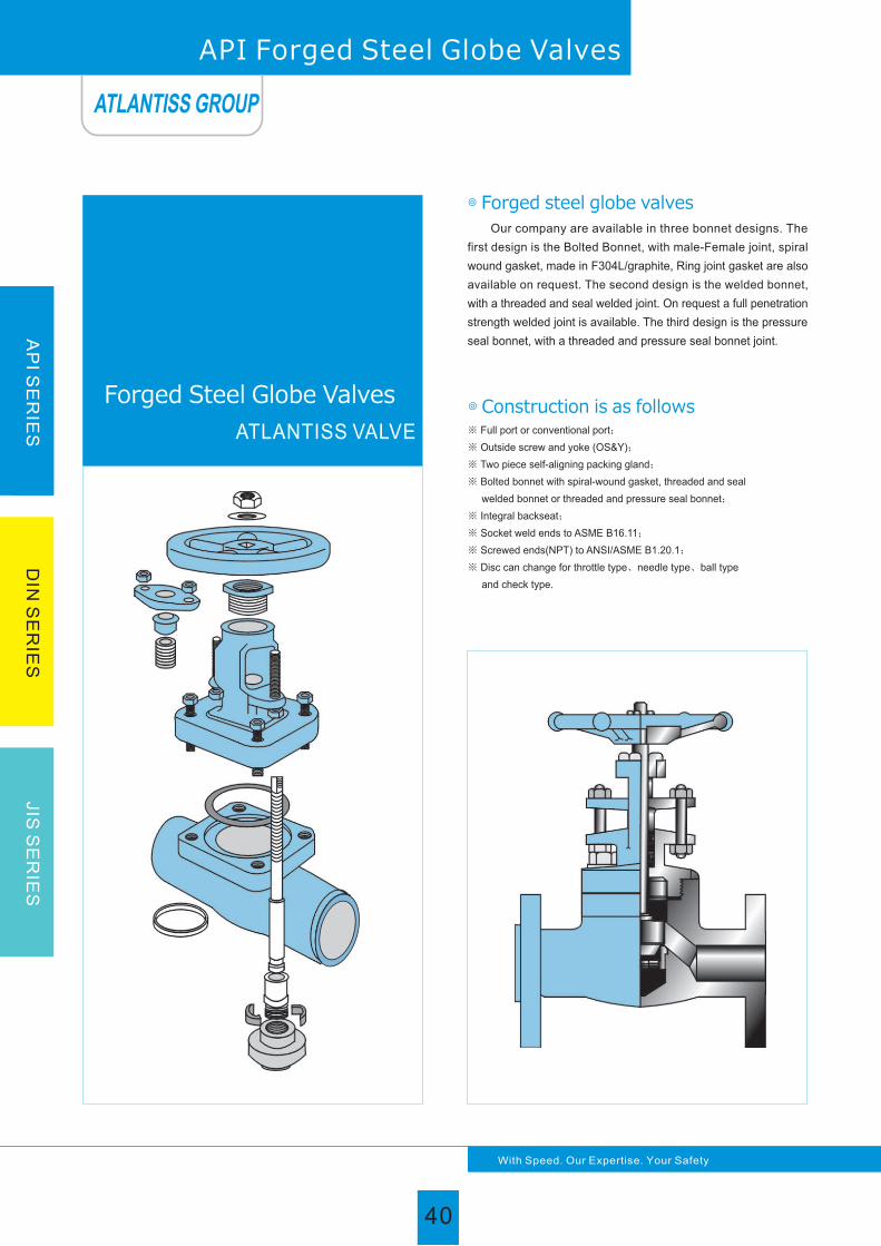
◎ Construction is as follows
◎ Forged steel globe valves
Our company are available in three bonnet designs. The
first design is the Bolted Bonnet, with male-Female joint, spiral
wound gasket, made in F304L/graphite, Ring joint gasket are also
available on request. The second design is the welded bonnet,
with a threaded and seal welded joint. On request a full penetration
strength welded joint is available. The third design is the pressure
seal bonnet, with a threaded and pressure seal bonnet joint.
※ Full port or conventional port;
※ Outside screw and yoke (OS&Y);
※ Two piece self-aligning packing gland;
※ Bolted bonnet with spiral-wound gasket, threaded and seal
welded bonnet or threaded and pressure seal bonnet;
※ Integral backseat;
※ Socket weld ends to ASME B16.11;
※ Screwed ends(NPT) to ANSI/ASME B1.20.1;
※ Disc can change for throttle type、needle type、ball type
and check type.
Forged Steel Globe Valves
ATLANTISS VALVE
AP
I SE
RIE
SD
IN S
ER
IES
JIS
SE
RIE
S
40
With Speed. Our Expertise. Your Safety
API Forged Steel Globe Valves
ATLANTISS GROUP
40

AP
I SE
RIE
SD
IN S
ER
IES
JIS
SE
RIE
S
41
With Speed. Our Expertise. Your Safety
API Forged Steel Globe Valves
1、Design and manufacture conform to BS5352 MSS SP-118;
2、Connection ends conform to:
1)Scoket welded ends conform to ANSI B16.11
2)Screw ends conform to ANSI B1.20.1
3)Butt-welded ends conform to ANSI B16.25
4)Flanged ends conform to ANSI B16.5
3、Test and inspection conform to:
API 598
4、Structure features:
Bolted bonnet, outside screw and yoke;
Welded bonnet, outside screw and yoke.
5、Materials conform to ANSI/ASTM.
6、Main materials:
A105;LF2;F5;F11;F22;F304;F304L;F316;
F316L;F321;F51;F53;Monel;Alloy Steel.
A105/F6aHFS F304(L)/304(L)
304+ graphite
A105/F6a LF2/304 F51/F51F316(L)/316(L)F11/F6aHFNO. Part name
Body1 A105 LF2 F11+HF F304(L) F316(L) F51A105+HF
Disc
Stem
3
4
F6a
410
F304
304
F6aHF
410
F304(L)
304(L)
F316(L)
316(L)
F51
F51
F6a
410
Pin
Hex nut
Stem nut
Locking nut
Nameplate
Handwheel
Packing
8
9
10
11
12
13
14
15
16
18
410
410
B7
A105
2H
410
35
AL
A197
410
304
L7
LF2
2H
410
35
AL
A197
410
410
B16
F11
2H
410
35
AL
A197
304
304
B8(M)
F304
8(M)
410
35
AL
A197
304
316
B8(M)
F304
8(M)
410
35
AL
A197
304
F51
B8M
F304
8M
410
35
AL
A197
Bonnet6 A105 LF2 F11 F304(L) F316(L) F51A105
410
410
B7
A105
2H
410
35
AL
A197
7 Bolt B7 B7 L7 B16 B8(M) B8(M) B8M
5 Gasket
Graphite Graphite Graphite Graphite Graphite Graphite Graphite
Gland flange
Gland
Gland eyebolt
Main part materials list
◎ Application standards
304+ graphite 304+ graphite 304+ graphite 304+ graphite 316+ graphite 316+ graphite
ATLANTISS GROUP
41

AP
I SE
RIE
SD
IN S
ER
IES
JIS
SE
RIE
S
42
With Speed. Our Expertise. Your Safety
◎CL800
R.P
F.P
L
W
H
d
Specification
Face to face
Handwheel diameter
Height
Weight(Kg)
Flow port dimension
Bolted bonnet, full port or red. port outside screw and yoke(OS & Y)
THD., SW or BW ends, design standard: BS5352
1/2
3/8
79
100
164
9
2.28
3/4
1/2
92
100
164
13
2.37
1
3/4
111
125
203
17.5
4.3
11 /4
1
120
160
224
23
5.75
11 /2
11 /4
152
160
260
30
7.8
2
11 /2
172
180
300
35
12.5
12 /2
2
200
200
355
46
17.5
Bolted bonnet, red. port or full port outside screw and yoke(OS&Y)
THD.,BW or SW ends, design standard: BS5352
◎CL900-CL1500
L
W
H
d
R.P
F.P
1/2
3/8
3/4
1/2
1
3/4
11 /4
1
11 /2
11 /4
2
11 /2
12 /2
2Specification
Face to face
Handwheel diameter
Height
Weight(Kg)
Flow port dimension
111
125
207
12
3.7
111
125
207
15
3.6
120
160
240
20
6.8
152
160
258
28
7.6
172
180
330
32
11.6
200
200
355
40
15
220
240
370
45
21.9
Welded bonnet (RJ), red. port, outside screw and yoke(OS & Y)
SW ends, design standard: ASME B16.34
L
W
H
d
F.P 1/2 3/4 1 11 /2 2Specification
Face to face
Handwheel diameter
Height
Weight(Kg)
Flow port dimension
150
130
293
11
10
150
130
300
14
10.3
210
250
390
19
22.4
235
300
435
28
38
235
300
435
35
38
◎CL2500
◎CL2500
Pressure seal bonnet, red. port, outside screw and yoke(OS & Y)
SW ends, design standard:ASME B16.34
L
W
H
d
F.P 1/2 3/4 1 11 /4 11 /2 2Specification
Face to face
Handwheel diameter
Height
Weight(Kg)
Flow port dimension
375
11
378
14
380
19
490
25
490
28
540
35
200 200 200 280 280 300
186 186 186 232 232 279
12.3 11.6 10.8 26.0 28.4 60
API Forged Steel THD and SW globe valves
ATLANTISS GROUP
42

AP
I SE
RIE
SD
IN S
ER
IES
JIS
SE
RIE
S
43
With Speed. Our Expertise. Your Safety
◎CL150-300-600
F.P
W
H
d
L(RF),L1(BW)
L(RTJ)
Specification
Face to face
(mm)
Handwheel diameter(mm)
Height(mm)
Flow port dimension(mm)
Weight (Kg)
1/2
216
216
125
207
12
11
3/4
229
229
125
207
15
13.2
1
254
254
160
230
20
17.4
11 /4
279
279
160
160
28
19
11 /2
305
305
180
300
32
24.5
2
368
371
200
355
40
31
Bolted bonnet, reducing port, outside screw and yoke(OS & Y)
Flanged or BW ends, design standard: BS5352
◎CL900-CL1500
Welded bonnet, reducing port, outside screw and yoke(OS & Y)
Flanged or BW ends, design standard: ASME B16.34
F.P
W
H
d
L(RF),L1(BW)
L(RTJ)
Specification
Face to face
(mm)
Handwheel diameter(mm)
Height(mm)
Flow port dimension(mm)
Weight (Kg)
1/2
264
264
125
207
11
19.5
3/4
273
273
160
240
14
21.5
1
308
308
200
258
19
42
11 /2
384
387
250
355
28
65
2
451
454
240
300
35
95
◎CL2500
F.P
W
H
d
L(RF),L1(BW)
L(RTJ)
Specification
Face to face
(mm)
Handwheel diameter(mm)
Height(mm)
Weight (Kg)
1/2
264
264
200
320
11
21.5
3/4
273
273
200
320
14
24.7
1
308
308
280
320
19
30.4
11 /4
349
349
280
440
25
48.1
11 /2
384
387
280
440
28
58.1
2
451
454
300
490
35
130
Pressure seal bonnet, reducing port, outside screw and yoke(OS & Y)
Flanged or BW ends, design standard: ASME B16.34
◎CL2500
1/2
108
152
165
100
180
164
9
3.45
2.3
3.8
2.8
5.6
3.4
3/4
117
178
190
100
184
164
13
4.00
3.6
5.1
4.0
7.8
4.7
1
127
203
216
125
217
203
17.5
6.19
7.8
7.2
8.5
12.5
9.2
11 /4
140
216
229
160
224
224
23
9.6
8.2
12
9.2
17
10.5
11 /2
165
229
241
160
260
260
30
10.5
12.0
13.5
12.6
23.5
13.3
2
203
267
292
180
300
300
35
17
15.0
19.7
16.8
38.8
18.9
Bolted bonnet, reducing port, outside screw and yoke(OS & Y)
Flanged or BW ends, design standard: BS5352
R.P
CL150
CL300
CL600
W
D
CL150
CL300
CL600
R F
BW
R F
BW
R F
BW
L(RF)
L1(BW)
HCL150/CL300
CL600
Specification
Face to face
Handwheel diameter
Height
Weight
(Kg)
Flow port dimension(mm)
Flow port dimension(mm)
API Forged Steel Flange Globe Valve
ATLANTISS GROUP
43

AP
I SE
RIE
SD
IN S
ER
IES
JIS
SE
RIE
S
With Speed. Our Expertise. Your Safety
◎ Construction is as follows
◎ Forged steel check valves
※ Full port or conventional port;
※ Lift type check valves;
※ Ball type check valves;
※ Swing type check valves;
※ Acceding to requirement equip inside spring;
※ Bolted bonnet with spiral-wound gasket, threaded and seal
welded bonnet or threaded and pressure seal bonnet;
※ Socket weld ends to ASME B16.11;
※ Screwed ends (NPT) to ANSI/ASME B1.20.1;
※ Disc can change for soft seal disc and ball disc.
Our company are available in three bonnet designs. The first
design is the Bolted Bonnet, with male-female joint, spiral wound
gasket, made in F304L/graphite, Ring joint gasket are also available
on request. The second design is the welded bonnet, with a threaded
and seal welded joint. On request a full penetration strength welded
joint is available. The third design is the pressure seal bonnet, with
a threaded and pressure seal bonnet joint. The check valves are
also available in three different design configurations. These are
piston check, ball check, or swing check designs.
API Forged Steel Check Valves
ATLANTISS VALVE
Forged Steel Check Valves
ATLANTISS GROUP
44

AP
I SE
RIE
SD
IN S
ER
IES
JIS
SE
RIE
S
45
With Speed. Our Expertise. Your Safety
API Forged Steel Check Valves
1、Design and manufacture conform to BS5352 MSS SP-118;
2、Connection ends conform to:
1)Scoket welded ends conform to ANSI B16.11
2)Screw ends conform to ANSI B1.20.1
3)Butt-welded ends conform to ANSI B16.25
4)Flanged ends conform to ANSI B16.5
3、Test and inspection conform to:API 598
4、Structure features:
Bolted bonnet
5、Materials conform to ANSI/ASTM.
6、Main materials:
A105;LF2;F5;F11;F22;F304;
F304L;F316;F316L;F321;F51;
F53;Monel;Alloy Steel.
A105/F6a A105/F6aHFS LF2/304 F51/F51F304(L)/304(L)F316(L)/316(L)
Body
Seat ring
Disc
Gasket
Bonnet
Bolt
Nameplate
1
2
3
5
6
7
15
A105
410
F6a
A105
AL
LF2
304
F304
LF2
AL
F11/F6aHF
F11
410HF
F6aHF
F11
AL
F304(L)
304(L)
F304(L)
F304(L)
AL
F316(L)
316(L)
F316(L)
F316(L)
AL
F51
F51
F51
F51
AL
A105
410HF
F6a
A105
AL
B7 L7 B16 B8(M) B8(M) B8MB7
32
33
34
35
36
Disc nut
Pin
430
2H
410
410
430
2H
410
410
304
8
304
304
STL
8
410
410
316(L)
8(M)
316(L)
304(L)
316(L)
8(M)
316(L)
316(L)
8M
F51
F51
STL
AL AL AL AL AL ALAL
NO. Part name
304+Graphite
Hinge
Revit
Steel ball
◎ Application standards
Main part materials list
304+Graphite 304+Graphite 304+Graphite 304+Graphite 316+Graphite 316+Graphite
ATLANTISS GROUP
45

46
With Speed. Our Expertise. Your Safety
AP
I SE
RIE
SD
IN S
ER
IES
JIS
SE
RIE
S
API Forged Steel Check Valves
BB, Full Bore or Red. Bore, THD or BW or SW ends, Design Standard: BS5352
◎CL900-CL1500
R.P
F.P
L
H
d
3/4
1/2
1
3/4
11 /4
1
11 /2
11 /4
2
11 /2Lift
Swing
Lift
Swing
Lift
Swing
Lift
Swing
1/2
3/8 2Specification
Face to face
Height
Weight(Kg)
Flow port dimension
-
-
92
92
61
61
7
8
1.5
1.5
111
111
78
78
12
10.5
3.4
3.4
111
111
78
78
15
13.5
3.3
3.3
120
120
84
84
20
18
4.2
4.2
152
120
103
101
28
24
6.3
5.0
172
140
118
120
32
29
10.5
8.5
200
178
132
133
40
45
12.5
10.9
1/22
BB, Red. Bore, Flanged or BW ends, Design Standard: BS5352
R.P
L(RF)
L1(BW)
H
d
11 /4 11 /2
108
153
165
77
61
10
3.6
3.0
3.7
3.2
4.0
3.4
1/2 3/4 1 2
Cl150
CL300
CL600
CL150
CL300/600
CL150
CL300
CL600
RF
BW
RF
BW
RF
BW
118
178
191
81
78
13
4.6
3.6
4.8
4.3
5.8
5.1
127
203
216
93
84
17.5
8.5
7.6
8.8
8.0
9.5
8.8
140
216
229
95
101
23
9.2
8.5
9.6
8.6
10.4
9.2
165
229
241
103
120
30
12.5
11.3
13.7
12.7
15.6
14.8
203
267
292
118
133
35
14.8
13.6
17.8
16.2
24.5
22.5
◎CL150-300-600
Specification
Face to face
Height
Flow port dimension(mm)
Weight (Kg)
R.P
L(RF)
L1(BW)
H
d
11 /4 11 /21/2 3/4 1 2
Cl150
CL300
CL600
CL150
CL300/600
CL150
CL300
CL600
RF
BW
RF
BW
RF
BW
◎CL150-300-600
Specification
Face to face
Height
Flow port dimension(mm)
Weight (Kg)
108
153
165
77
61
10.5
3.6
3.0
3.7
3.2
4.0
3.4
118
178
191
81
78
13.5
4.6
3.6
4.8
4.3
5.8
5.1
127
203
216
93
84
18
8.5
7.6
8.8
8.0
9.5
8.8
140
216
229
95
101
24
9.2
8.5
9.6
8.6
10.4
9.2
165
229
241
103
120
29
12.5
11.3
13.7
12.7
15.6
14.8
203
267
292
118
133
36.5
14.8
13.6
17.8
16.2
24.5
22.5
BB, Red. Bore, Flanged or BW ends, Design Standard: BS5352
BB, Full Bore or Red. Bore, THD or BW or SW ends, Design Standard: BS5352
◎CL800
R.P
F.P
L
H
d
3/4
1/2
1
3/4
11 /4
1
11 /2
11 /4
2
11 /2
Lift
Swing
Lift
Swing
Lift
Swing
Lift
Swing
1/2
3/8
79
79
61
61
9
10.5
1.5
1.5
92
92
61
61
13
13.5
1.7
1.7
111
111
78
78
17.5
18
3.3
3.3
120
120
84
84
23
24
4.2
4.2
152
120
84
84
30
29
4.2
4.2
172
140
118
120
35
36.5
10.5
8.5
200
178
132
133
46
45
12.5
10.9
2Specification
Face to face
Height
Weight(Kg)
Flow port dimension
-
-
1/22
ATLANTISS GROUP
46

47
With Speed. Our Expertise. Your Safety
AP
I SE
RIE
SD
IN S
ER
IES
JIS
SE
RIE
S
◎ Product structural features Gate valve seal acc. to DIN is applicable to the cutting and
connection of pipelines medium that are used in various in diestrus
such as petroleum, chemical industry, pharmacy, chemical fertilizer,
electric power industry, etc under nominal pressure of PN1.6~16MPa
and working temperature within-industries -110~600℃
◎ Main structural features1. This product has logical structure, reliable seal, excellent perfor-
mance and nice design.
2. The seal surface is build-up welding with Wc-Co hard alloy, which
is attrition-resistant, corrosion-resistant,has good friction resistant
and long life.
3. The stem quenched and tempered, and its surface is treated by
nitrating treatment, thus it has good corrosion resistant and
friction resistant.
4. It has double seal capability, which is more reliable.
5. The part material, flange and butt weld end dimension may be
selected according to current operating condition and users'
requirement, so that meeting the requirements of various
engineering.
◎ Technical specification
Structural Formation: BB-BG-OS & Y
Driving Manner: Hand-Operated
Driving Manner: Electric-Actuated
Design Standard: DIN3352
Face to Face: DIN3202
Flange Ends: DIN2543-2547
Test & Inspection: DIN3230
Notes: The size of serial, valve connecting flange can be design
according to customers' requirement.
DIN Gate Valve
Products performance specification
Nominal Pressure(MPa)
1.6
2.5
4.0
6.4
Shell Test (MPa)
2.4
3.75
6.0
9.6
Sealing Test (MPa)
1.76
2.75
4.4
7.04
Suitable Temp(℃) Suitable Medium
Water Oil & Gas-110~600℃
ATLANTISS VALVE
DIN Gate Valve
ATLANTISS GROUP
47

AP
I SE
RIE
SD
IN S
ER
IES
JIS
SE
RIE
S
With Speed. Our Expertise. Your Safety
DIN Gate Valve
◎ Technical specification
◎ Structural Formation: BB-BG-OS & Y
◎ Driving Manner: Hand-Operated
◎ Driving Manner: Electric-Actuated
◎ Design Standard: DIN3352
◎ Face to Face: DIN3202
◎ Flange Ends: DIN2543-2547
◎ Test & Inspection: DIN3230
◎ Notes: The size of serial, valve connecting
flange can be design according to
customers' requirement.
Main part material of Cast steel
GS-C25Body
13Cr
13Cr STLSTL STL1.4308 1.4408 STL
GS-C25 1.4308 1.4408
13Cr STL13Cr 1.4308 1.4408STL STL
Stem
Wedge Disc
Wedge DiscSealing Face
Seat RingSealing Face
1.4308 1.4408
1.4408 1.4306 1.4301
1.4408 STL STL STL STL STL STL
1.4408 1.4306 1.4301
1.4408 1.4408 STL STL STL
Stem
Wedge Disc
Wedge DiscSealing Face
Seat RingSealing Face
1.43061.4306
1.4306
1.43011.4301
1.4301
Body
F304
1.4308 STL STL
1.4308
1.4308 1.4308 STL
Main part material of Stainless steel
ATLANTISS GROUP
48

AP
I SE
RIE
SD
IN S
ER
IES
JIS
SE
RIE
S
49
With Speed. Our Expertise. Your Safety
DIN Gate Valve
Pressure(MPa)
Size mm
L
H
W
PN6.4MPa
50
250
404
200
20
65
290
456
280
35
80
310
604
300
52
100
350
607
350
66
125
400
720
350
103
150
450
780
400
140
200
550
875
450
230
250
650
1260
500
300
300
750
1480
500
510
350
850
1605
600
780
400
950
1788
650
940
450
1050
1956
700
1300
500
1150
2168
700
1600
600
1350
2601
800
1850Weight(kg)
Size mm
L
H
W
Weight(kg)
Pressure(MPa)
PN4.0MPa
50
250
404
200
18
65
290
456
280
32
80
310
604
300
47
100
350
607
350
60
125
400
720
350
95
150
450
780
400
130
200
550
875
450
220
250
650
1260
500
290
300
750
1480
500
490
350
850
1605
600
760
400
950
1788
650
900
450
1050
1956
700
1250
500
1150
2168
700
1450
600
1350
2601
800
1700
80
280
530
280
43
100
300
607
300
58
125
325
720
350
82
150
350
790
350
103
200
400
885
400
180
250
450
1014
450
265
300
500
1190
500
385
350
550
1350
600
547
400
600
1460
600
835
450
650
1630
650
1050
500
700
1800
700
1130
600
800
2200
800
1500
PN2.5MPaPressure
(MPa)
Size mm
L
H
W
Weight(kg)
50
250
417
200
16
65
270
452
280
31
PN1.6MPa
80
280
530
280
30
100
300
607
300
55
125
325
720
350
75
150
350
790
350
98
200
400
885
400
150
250
450
1014
450
245
300
500
1190
500
353
350
550
1350
600
490
400
600
1460
600
750
450
650
1630
650
985
500
700
1800
700
1063
600
800
2200
800
1390
Size mm
L
H
W
Weight(kg)
50
250
417
200
16
65
270
452
280
25
Pressure
(MPa)
Size main dimensions of Gate Valve
ATLANTISS GROUP
49

With Speed. Our Expertise. Your Safety
AP
I SE
RIE
SD
IN S
ER
IES
JIS
SE
RIE
S
1. This product has logical structure, reliable seal, excellent perfor-
mance and nice design.
2. The seal surface is build-up welding with Co hard alloy, which
is attrition-resistant, corrosion-resistant, has good friction resistant
and long life.
3. The stem quenched and tempered, and its surface is treated by
nitrating treatment, thus it has good corrosion resistant and friction
resistant.
4. The part material, flange and butt weld end dimension may be
selected according to current operating condition and users'
requirement, so that meeting the requirements of various
engineering.
Globe valve seal acc. to DIN is applicable to the cutting and
connection of pipelines medium that are used in various industries
such as petroleum, chemical industry, pharmacy, chemical fertilizer,
electric power industry etc under nominal pressure of PN1.6~16MPa
and working temperature within -110~600℃
Structural Formation: BB-BG-OS & Y
Driving Manner: Hand-Operated
Driving Manner: Electric-Actuated
Design Standard: DIN3356
Face to Face: DIN3202
Flange Ends: DIN2543-2545
Test & Inspection: DIN3230
Notes: The size of serial, valve connecting flange can be design
according to customers' requirement
◎ Product structural features
◎ Main structural features
◎ Technical specification
DIN Globe Valve
Products performance specification
Nominal Pressure(MPa)
1.6
2.5
4.0
6.4
Shell Test (MPa)
2.4
3.75
6.0
9.6
Sealing Test (MPa)
1.76
2.75
4.4
7.04
Suitable Temp(℃) Suitable Medium
Water Oil & Gas-110~600℃
ATLANTISS VALVE
DIN Globe Valve
ATLANTISS GROUP
50

51
With Speed. Our Expertise. Your Safety
AP
I SE
RIE
SD
IN S
ER
IES
JIS
SE
RIE
S
DIN Globe Valve
◎ Technical specification
◎ Structural Formation: BB-BG-OS & Y
◎ Driving Manner: Hand-Operated
◎ Driving Manner: Electric-Actuated
◎ Design Standard: DIN3356
◎ Face to Face: DIN3202
◎ Flange Ends: DIN2543-2545
◎ Test & Inspection: DIN3230
◎ Notes: The size of serial, valve
connecting flange can be design
according to customers'
requirement.
Main part material of Cast steel
GS-C25Body
13Cr
13Cr STLSTL STL1.4308 1.4408 STL
1.4408 1.4306 1.4301
1.4408 STL STL STL STL STL STL
GS-C25 1.4308 1.4408
1.4408 1.4306 1.4301
13Cr STL13Cr 1.4308 1.4408STL STL
1.4408 1.4408 STL STL STL
Stem
Stem
Disc
Disc
DiscSealing Face
Seat RingSealing Face
Wedge DiscSealing Face
RingSealing Face
1.43061.4306
1.4306
1.43011.4301
1.4301
1.4308 1.4408
Body
F304
1.4308 STL STL
1.4308
1.4308 1.4308 STL
Main part material of Stainless steel
ATLANTISS GROUP
51

Size main dimensions of Globe Valve
Pressure(MPa)
Size mm
L
H
W
Weight(kg)
50
230
325
200
24
65
290
370
200
30
80
310
430
250
41
100
350
480
300
60
125
400
532
350
85
150
480
589
400
110
200
600
783
450
225
250
650
888
500
460
PN4.0MPa
15
130
240
120
6
20
150
260
140
7.5
25
160
276
160
8
32
180
285
160
9
40
200
300
180
15
Pressure(MPa)
Size mm
L
H
W
Weight(kg)
50
230
325
200
22
65
290
363
200
27
80
310
415
250
38
100
350
453
300
55
125
400
505
350
82
150
480
556
400
105
200
600
744
450
220
250
650
864
500
450
PN2.5MPa
15
130
240
120
6
20
150
260
140
7.5
25
160
276
160
8
32
180
285
160
9
40
200
300
180
14
Pressure(MPa)
Size mm
L
H
W
Weight(kg)
PN1.6MPa
50
230
305
200
20
65
290
354
200
25
80
310
402
750
35
100
350
437
250
50
125
400
496
300
75
150
480
541
350
100
200
600
699
400
210
250
650
815
450
446
15
130
240
120
5.2
20
150
260
140
7.1
25
160
276
160
7.4
32
180
285
160
8.5
40
200
300
180
13
300
750
965
550
670
350
850
1285
600
830
400
950
1512
600
1120
300
750
948
550
660
350
850
1269
600
810
400
950
1450
600
1100
300
750
914
500
648
350
850
1189
550
805
400
950
1350
600
1050
Pressure(MPa)
Size mm
L
H
W
Weight(kg)
PN10.0MPa
50
300
325
200
27
65
340
363
200
34
80
380
415
250
46
100
450
453
300
67
125
500
505
350
95
150
550
556
400
125
200
650
744
450
235
250
775
864
500
480
300
900
948
550
690
40
260
300
180
19
Pressure(MPa)
Size mm
L
H
W
Weight(kg)
PN6.4MPa
50
300
305
200
26
65
340
354
200
33
80
380
402
750
45
100
430
437
250
65
125
500
496
300
90
150
550
541
350
120
200
650
699
400
230
250
775
815
450
470
300
900
914
500
680
40
260
300
180
17
350
1025
1269
600
860
400
1150
1450
600
1150
350
1025
1189
550
850
400
1150
1350
600
1130
AP
I SE
RIE
SD
IN S
ER
IES
JIS
SE
RIE
S
With Speed. Our Expertise. Your Safety
DIN Globe Valve
ATLANTISS GROUP
52

AP
I SE
RIE
SD
IN S
ER
IES
JIS
SE
RIE
S
53
With Speed. Our Expertise. Your Safety
Products performance specification
Nominal Pressure(MPa)
1.6
2.5
4.0
6.4
Shell Test (MPa)
2.4
3.75
6.0
9.6
Sealing Test (MPa)
1.76
2.75
4.4
7.04
Suitable Temp(℃) Suitable Medium
Water Oil & Gas-110~600℃
1. This product has logical structure, reliable seal, excellent perfo-
rmance and nice design.
2. The seal surface is build-up welding with Co hard alloy, which
is attrition-resistant, corrosion-resistant, has good friction
resistant and long life.
3. The part material, flange and butt weld end dimension may be
selected according to current operating condition and users'
requirement, so that meeting the requirements of various
engineering.
Check valve seal acc. to DIN is applicable to the cutting and
connection of pipelines medium that are used in various industries
such as petroleum, chemical industry, pharmacy, chemical fertilizer,
electric power industry, etc under nominal pressure of PN1.6~
16MPa, and working temperature within -110~600℃
Structural Formation: BB-BG-OS & Y
Driving Manner: Hand-Operated
Driving Manner: Electric-Actuated
Design Standard: DIN3356
Face to Face: DIN3202
Flange Ends: DIN2543-2545
Test & Inspection: DIN3230
Notes: The size of serial, valve connecting flange can be design
according to customers' requirement
◎ Product structural features
◎ Main structural features
◎ Technical specification
ATLANTISS VALVE
DIN Check Valve
DIN Check Valve
ATLANTISS GROUP
53

AP
I SE
RIE
SD
IN S
ER
IES
JIS
SE
RIE
S
With Speed. Our Expertise. Your Safety
DIN Check Valve
◎ Technical specification
◎ Structural Formation: BB-BG-OS & Y
◎ Driving Manner: Wc-Co Hand-Operated
◎ Driving Manner: Electric-Actuated
◎ Design Standard: DIN3356
◎ Face to Face: DIN3202
◎ Flange Ends: DIN2543-2547
◎ Test & Inspection: DIN3230
◎ Notes: The size of serial, valve
connecting flange can be design
according to customers'
requirement.
Main part material of Cast steel
GS-C25Body
GS-C25 1.4308 1.4408
13Cr STLSTL STL1.4308 1.4408 STL
13Cr STL13Cr 1.4308 1.4408STL STLDisc
Sealing Face
Seat RingSealing Face
Cover
1.4408 1.4306 1.4301
1.4408 STL STL STL STL STL STL
1.4408 1.4306 1.4301
1.4408 1.4408 STL STL STLWedge DiscSealing Face
Seat RingSealing Face
1.43061.4306
1.4306
1.43011.4301
1.4301
Body
1.4308 STL STL
1.4308
1.4308 1.4308 STL
Main part material of Stainless steel
Cover 1.4308
ATLANTISS GROUP
54

AP
I SE
RIE
SD
IN S
ER
IES
JIS
SE
RIE
S
55
With Speed. Our Expertise. Your Safety
DIN Swing Check Valve
Size main dimensions of Swing Check Valve
Pressure(MPa)
Size mm
L
H
Weight(kg)
50
325
22
65
370
31
80
430
41.5
100
480
65
125
532
100
150
589
136
200
783
220
250
888
305
300
965
400
350
1285
450
400
1512
510
PN4.0MPa
230 290 310 350 400 480 550 650 750 850 950
Weight(kg)
50
325
22
65
363
29
80
415
38
100
453
61
125
505
96
150
556
132
200
744
213
250
864
297
300
948
375
350
1269
415
400
1450
480
Pressure(MPa)
Size mm
L
H
PN2.5MPa
230 290 310 350 400 480 550 650 750 850 950
Pressure(MPa)
Size mm
L
H
Weight(kg)
PN1.6MPa
50
230
305
21
65
290
354
28
80
310
402
38
100
350
437
58
125
400
496
92
150
480
541
130
200
550
699
210
250
650
815
295
300
750
914
365
350
850
1189
410
400
950
1350
460
Weight(kg)
Pressure(MPa)
Size mm
L
H
PN10.0MPa
50
325
30
65
363
40
80
415
60
100
453
92
125
505
140
150
556
195
200
744
280
250
864
406
300
948
670
350
1269
850
400
1450
1260
300 340 380 430 500 550 650 775 900 1025 1150
Pressure(MPa)
Size mm
L
H
Weight(kg)
PN6.4MPa
50
300
65
340
80
380
100
430
125
500
150
550
200
650
250
775
300
900
350
1025
400
1150
305
27
354
37
402
57
437
87
496
135
541
184
699
266
815
396
914
643
1189
815
1350
1230
ATLANTISS GROUP
55

AP
I SE
RIE
SD
IN S
ER
IES
JIS
SE
RIE
S
With Speed. Our Expertise. Your Safety
DIN Lift Check Valve
Pressure(MPa)
Size mm
L
H
Weight(kg)
PN4.0MPa
50
230
325
13
65
290
370
23
80
310
430
34
100
350
480
46
125
400
532
60
150
480
589
85
200
600
783
190
250
888
280
300
965
430
350
1285
550
400
1512
680
650 750 850 950
Weight(kg)
Pressure(MPa)
Size mm
L
H
PN2.5MPa
50
230
325
12
65
290
363
22
80
310
415
33
100
350
453
44
125
400
505
55
150
480
556
78
200
600
744
180
250
864
270
300
948
410
350
1269
520
400
1450
650
650 750 850 950
Pressure(MPa)
Size mm
L
H
Weight(kg)
PN1.6MPa
50
230
305
10
65
290
354
20
80
310
402
30
100
350
437
39
125
400
496
50
150
480
541
70
200
600
699
161
250
650
815
251
300
750
914
395
350
850
1189
500
400
950
1350
618
Size main dimensions of Lift Check Valve
ATLANTISS GROUP
56

AP
I SE
RIE
SD
IN S
ER
IES
JIS
SE
RIE
S
With Speed. Our Expertise. Your Safety
57
Products performance specification
Nominal Pressure(MPa)
1.6
2.5
4.0
6.4
Shell Test (MPa)
2.4
3.75
6.0
9.6
Sealing Test (MPa)
1.76
2.75
4.4
7.04
Suitable Temp(℃) Suitable Medium
Water Oil & Gas-196~150℃
10.0 10.5 11
1. The product has indication of open-close and locking system;
2. The stem has function of unti-blow out, anti fire-safe and
anti-static function;
3. The part material flange, and butting weld end dimension may
be selected according to current operation condition and user's
requirement, so that meeting the requirement of various
engineering.
Ball valve seal acc. to DIN is applicable to the cutting and
connection of pipelines medium that are used in various industries
such as petroleum, chemical industry, pharmacy, chemical fertilizer,
electric power industry etc under nominal pressure of PN1.6~10MPa
and working temperature within -196~150℃.
Structural Formation: BB-BG-OS & Y
Driving Manner: Hand-Operated
Driving Manner: Electric-Actuated
Design Standard: DIN3356
Face to Face: DIN3202
Flange Ends: DIN2543-2545
Test & Inspection: DIN3230
Notes: The size of serial, valve connecting flange can be design
according to customers' requirement
◎ Product structural features
◎ Main structural features
◎ Technical specification
ATLANTISS VALVE
DIN Ball Valve
DIN Ball Valve
ATLANTISS GROUP
57

AP
I SE
RIE
SD
IN S
ER
IES
JIS
SE
RIE
S
With Speed. Our Expertise. Your Safety
DIN Floating Ball Valve
Size main dimensions of Floating Ball Valve
Spring & Ball
DN
L
H
H1
L
H
H1
PN 16
DN
L
H
H1
Wt(Kg)
15
130
78
140
3
20
140
84
160
4
25
150
95
180
5
32
165
150
250
10
40
180
150
300
14
50
200
190
350
20
65
220
195
350
25
80
250
215
400
30
100
280
250
600
40
125
320
285
600
65
150
360
330
800
73
200
400
370
1000
85
DN
Wt(Kg)
15
130
82
140
3
20
140
100
160
4
25
150
104
180
5
32
165
150
250
10
40
180
150
300
14
50
200
190
350
20
65
220
195
350
25
80
250
215
400
50
100
280
250
600
70
125
403
260
600
80
150
403
275
800
85
200
502
335
800
101
PN 40
Wt(Kg)
15
130
78
140
3
20
140
84
160
4
25
150
95
180
5
32
165
150
250
10
40
180
150
300
14
50
200
190
350
20
65
220
195
350
25
80
250
215
400
30
100
280
250
600
40
125
320
285
600
65
150
360
330
800
73
200
400
370
1000
85
PN 25
ATLANTISS GROUP
58

With Speed. Our Expertise. Your Safety
AP
I SE
RIE
SD
IN S
ER
IES
JIS
SE
RIE
S
LR F
B W
H
H1
W
L R F
H
H1
W
Wt(Kg)
L R F
H
H1
W
Wt(Kg)
Size main dimensions of Trunnion Ball Valve
PN 16/25
DN
LR F
B W
H
H1
W
Wt(Kg)
50
179
216
107
102
230
12
65
191
241
125
114
400
16
80
203
283
152
127
400
22
100
229
305
178
152
650
35
125
356
381
300
184
1050
58
150
394
457
330
219
105
74
200
457
521
398
273
600
205
250
533
559
495
360
600
322
300
610
635
580
395
800
460
350
686
762
625
430
800
576
400
762
838
670
470
800
864
450
846
914
698
550
800
1280
500
914
991
840
580
800
1600
600
1067
1143
1050
700
800
3540
700
1245
1346
1100
800
800
4500
800
1372
1524
1150
950
800
5940
900
1524
1727
1247
1100
800
7540
1000
1753
1880
1374
1200
800
9320
DN 50
292
108
114
600
23
65
330
155
124
600
38
80
356
197
133
600
55
100
432
235
159
600
102
150
559
300
250
600
232
200
660
374
294
800
290
250
787
445
395
800
710
300
838
512
445
800
960
350
889
550
500
800
1700
400
991
615
530
800
1970
500
1194
810
660
800
3250
600
1397
1010
800
800
5800
700
1579
1180
900
800
6700
PN 100
DN
Wt(Kg)
50
216
216
107
102
230
15
65
241
241
125
114
400
24
80
283
283
152
127
400
30
100
305
305
178
152
650
55
125
381
381
300
184
1050
87
150
403
457
330
219
1050
118
200
502
521
398
273
600
255
250
568
559
495
360
600
370
300
648
635
580
395
800
533
350
762
762
625
430
800
640
400
838
838
670
470
800
1030
450
914
914
698
550
800
1542
500
991
991
840
580
800
2100
600
1143
1143
1050
700
800
4200
700
1346
1346
1100
800
800
5300
800
1524
1524
1150
950
800
7860
900
1727
1727
1247
1100
800
8684
1000
1880
1880
1374
1200
800
10300
PN 40
DN 50
292
108
114
600
23
65
330
155
124
600
35
80
356
197
133
600
49
100
406
235
159
600
91
150
495
300
250
600
192
200
597
374
294
800
355
250
673
445
395
800
640
300
762
512
445
800
880
350
826
550
500
800
1100
400
902
615
530
800
1540
500
1054
810
660
800
2800
600
1232
1010
800
800
5300
700
1397
1180
900
800
5700
PN 64
DIN Trunnion Ball Valve
ATLANTISS GROUP
59
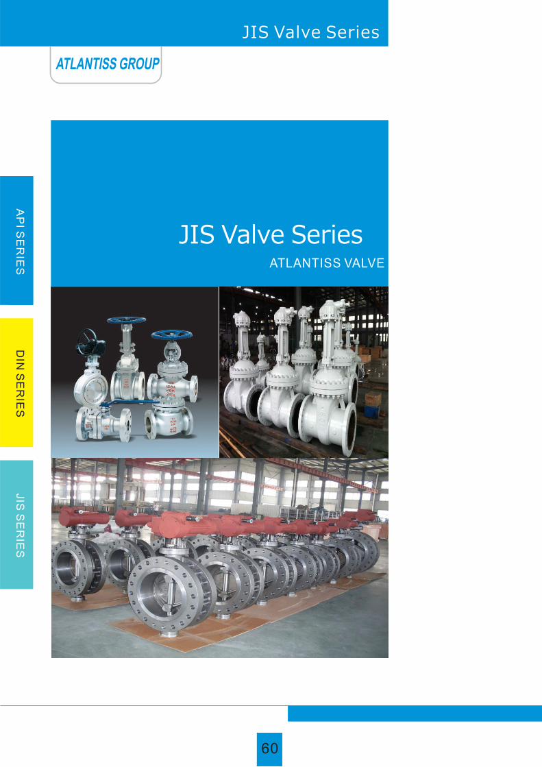
60
With Speed. Our Expertise. Your Safety
AP
I SE
RIE
SD
IN S
ER
IES
JIS
SE
RIE
S
JIS Valve Series
JIS Valve Series ATLANTISS VALVE
ATLANTISS GROUP
60

With Speed. Our Expertise. Your Safety
AP
I SE
RIE
SD
IN S
ER
IES
JIS
SE
RIE
S
Parts and material list
Parts nameMaterial
Body
Gasket
Seat ring
Gate
Stem
Backseat bushing
Packing
Gland
Gland eyebolt
Eyebolt nut
Eyebolt pin
Gland flange
Bonnet bolt
Bonnet nut
Bonnet
Nipple
Stem nut
Yoke sleeve nut
Hand wheel
Hand wheel nut
WCB/Trim 1 WCB/Trim 5 WCB/Trim 8
ASTM A216 WCB
A105+STL
ASTM A216 WCB+STL
ASTM A182 F6a
ASTM A182 F6a
Graphite
ASTM A182 F6a
ASTM A193 B7
ASTM A194 2H
ASTM A216 WCB
ASTM A193 B7
ASTM A194 2H
ASTM A216 WCB
Carbon steel
Copper alloy
Carbon steel
Carbon steel
Carbon steel
ASTM A351 CF8M
316 + Graphite
ASTM A351 CF8M
ASTM A351 CF8M
ASTM A182 F316
ASTM A351 CF8M
Graphite
ASTM A182 F316
ASTM A193 B8M
ASTM A194 8M
316ss
ASTM A351 CF8M
ASTM A193 B8M
ASTM A194 8M
ASTM A351 CF8M
Carbon steel
Copper alloy
Carbon steel
Carbon steel
Carbon steel
CF8/304 CF8M/316
ASTM A351 CF8
304 + Graphite
ASTM A351 CF8
ASTM A351 CF8
ASTM A182 F304
ASTM A351 CF8
Graphite
ASTM A182 F304
ASTM A193 B8
ASTM A194 8
304ss
ASTM A351 CF8
ASTM A193 B8
ASTM A194 8
ASTM A351 CF8
Carbon steel
Copper alloy
Carbon steel
Carbon steel
Carbon steel
ASTM A216 WCB
A105+13Cr
ASTM A216 WCB+13Cr
ASTM A182 F6a
ASTM A182 F6a
Graphite
ASTM A182 F6a
ASTM A193 B7
ASTM A194 2H
ASTM AISI 1045
ASTM A216 WCB
ASTM A193 B7
ASTM A194 2H
ASTM A216 WCB
Carbon steel
Copper alloy
Carbon steel
Carbon steel
Carbon steel
ASTM A216 WCB
A105+STL
ASTM A216 WCB+13Cr
ASTM A182 F6a
ASTM A182 F6a
Graphite
ASTM A182 F6a
ASTM A193 B7
ASTM A194 2H
ASTM A216 WCB
ASTM A193 B7
ASTM A194 2H
ASTM A216 WCB
Carbon steel
Copper alloy
Carbon steel
Carbon steel
Carbon steel
ASTM AISI 1045 ASTM AISI 1045
Note: The chart above only l ists out some common composit ion of steel gate valve parts. We may provide other different parts material
composit ion acording to the customer's request or the actual valve working condit ion.
304 +Graphite
JIS Gate Valve
ATLANTISS GROUP
61

Size main dimensions of Gate Valve
Capability criterion
Our company JIS gate valve usually be reliably used in steam, air, coat gas, oil or oil gas etc high or low-pressure condition. Middle or low-pressure valve
normal valve normal adopt taper disc seating structure, but the large diameter and high pressure valve adopt sideway disc sealing structure, the medium flow
from high to low position, it use medium self pressure seal, so the sealing is very reliable and the operated torque is more light. According to condition, the
valve can be apply more kinds of material and connection type between bonnet and body and can be reach to more requirements of user.
◎ Features
◎ Construction as follows1. Full Bore/Reduce bore
2. Outside screw stem and rising Yoke
mm in L D D1 D2 b n-φd D0H
DN 10K
15
20
25
40
50
65
80
100
125
150
200
250
300
350
400
450
500
1 /2
3 /4
1
11 /2
2
12 /2
3
4
5
6
8
10
12
14
16
18
20
108
117
127
165
178
190
203
229
250
267
292
330
356
381
406
432
457
95
100
125
140
155
175
185
210
210
280
330
400
445
490
560
620
675
52
58
70
85
100
120
130
155
185
215
265
325
370
415
475
530
585
12
14
14
16
16
18
18
18
2
22
22
24
24
26
28
30
30
4-φ15
4-φ15
4-φ19
4-φ19
4-φ19
4-φ19
8-φ19
8-φ19
8-φ23
8-φ23
12-φ23
12-φ25
16-φ25
16-φ25
16-φ27
20-φ27
20-φ27
179
198
255
323
409
535
570
590
605
630
960
1158
1378
1543
1738
1959
2214
70
75
90
105
120
140
150
175
185
240
290
355
400
445
510
565
620
100
100
130
160
160
250
250
250
280
300
350
400
450
500
600
600
680
Design And
Manufacture
JIS B2071 B2081
Face To Face
JIS B2002
Flange Dimension
JIS B2212 B2214
Pressure-
Temperture rating
JIS B2071 B2081
Inspection And Test
JIS B2003
Suitable Temperature ≤425℃
SCPL1
-45~150℃
Body material
Appropriate Medium
SPCH2-11
≤540℃
SPCH2-32
Water Steam Oil Goods
SCS13A SCS19A
≤275℃ ≤200℃
Nitric Acid
SCS14A SCS16A
≤275℃ ≤200℃
Acetic Acid Liquid Ammonia
3. Detachable seat and Back-seat
4. Two piece self aligning packing gland
Standard
62
With Speed. Our Expertise. Your Safety
AP
I SE
RIE
SD
IN S
ER
IES
JIS
SE
RIE
S
JIS Gate Valve
ATLANTISS GROUP
62

With Speed. Our Expertise. Your Safety
JIS Gate ValveA
PI S
ER
IES
DIN
SE
RIE
SJIS
SE
RIE
S
mm in L D D1 D2 b n-φd
15
20
25
40
50
65
80
100
125
150
200
250
300
350
400
450
140
152
165
190
216
241
283
305
381
403
419
457
502
762
838
914
95
100
125
140
155
175
200
225
270
305
350
430
480
540
605
675
52
58
70
85
100
120
135
160
195
230
275
345
395
440
495
560
14
16
16
18
18
20
22
24
26
28
30
34
35
40
46
48
4-15
4-15
4-19
4-19
8-φ19
8-φ19
8-φ23
8-φ23
8-25
12-φ25
12-φ25
12-φ27
16-φ27
16-φ33
16-φ33
20-φ33
179
202
265
415
480
510
580
700
845
940
1190
1390
1600
1750
1900
2320
70
75
90
105
120
140
160
185
225
260
305
380
430
480
540
605
130
130
160
200
200
250
280
350
400
400
450
500
500
600
600
650
D0H
20KDN
1 /2
3 /4
1
11 /2
2
12 /2
3
4
5
6
8
10
12
14
16
18
15
20
25
40
50
65
80
100
125
150
200
250
300
350
400
1 /2
3 /4
1
11 /2
2
12 /2
3
4
5
6
8
10
12
14
16
165
190
216
241
292
330
356
432
508
559
660
787
838
889
991
115
120
130
160
165
200
210
250
300
355
405
475
540
585
645
80
85
95
120
130
160
170
205
250
295
345
410
470
515
570
55
60
70
90
105
130
140
165
200
240
290
355
410
455
515
20
20
22
24
26
30
32
36
40
44
50
56
60
64
70
4-φ19
4-φ19
4-φ19
4-φ23
8-φ19
8-23
8-23
8-25
8-27
12-33
12-33
12-33
16-39
16-39
16-39
179
202
265
415
480
510
580
700
845
940
1190
1390
1600
1750
1900
160
200
200
200
280
280
300
400
500
500
500
600
650
650
700
mm in L D D1 D2 b n-φd D0H
40KDN
Size main dimensions of Gate Valve
ATLANTISS GROUP
63

With Speed. Our Expertise. Your Safety
AP
I SE
RIE
SD
IN S
ER
IES
JIS
SE
RIE
S
JIS Globe Valve
Parts and material list
Parts nameMaterial
WCB/Trim 1 WCB/Trim 5 WCB/Trim 8 CF8/304 CF8M/316
Body
Disc
Stem
Disc nut
Bonnet nut
Bonnet bolt
Gasket
Backseat bushing
Bonnet
Packing
Eyebolt pin
Gland eyebolt
Gland
Gland flange
Eyebolt nut
Stem nut
Hand wheel
Hand wheel nut
ASTM A216 WCB+STL
ASTM A216 WCB+STL
ASTM A182 F6a
ASTM A216 WCB
ASTM A194 2H
ASTM A193 B7
304 +Graphite
ASTM A182 F6a
ASTM A216 WCB
Graphite
ASTM A193 B7
ASTM A182 F6a
ASTM A216 WCB
ASTM A194 2H
Copper alloy
Carbon steel
Carbon steel
ASTM A351 CF8
ASTM A351 CF8
ASTM A182 F304
ASTM A351 CF8
ASTM A194 8
ASTM A193 B8
304 + Graphite
ASTM A351 CF8
ASTM A351 CF8
Graphite
304ss
ASTM A193 B8
ASTM A182 F304
ASTM A351 CF8
ASTM A194 8
Copper alloy
Carbon steel
Carbon steel
ASTM A351 CF8M
ASTM A351 CF8M
ASTM A182 F316
ASTM A351 CF8M
ASTM A194 8M
ASTM A193 B8M
316 + Graphite
ASTM A351 CF8M
ASTM A351 CF8M
Graphite
316ss
ASTM A193 B8M
ASTM A182 F316
ASTM A351 CF8M
ASTM A194 8M
Copper alloy
Carbon steel
Carbon steel
ASTM A216 WCB+13Cr
ASTM A216 WCB+13Cr
ASTM A182 F6a
ASTM A216 WCB
ASTM A194 2H
ASTM A193 B7
304+Graphite
ASTM A182 F6a
ASTM A216 WCB
Graphite
ASTM A193 B7
ASTM A182 F6a
ASTM A216 WCB
ASTM A194 2H
Copper alloy
Carbon steel
Carbon steel
ASTM A216 WCB+STL
ASTM A216 WCB+13Cr
ASTM A182 F6a
ASTM A216 WCB
ASTM A194 2H
ASTM A193 B7
304+Graphite
ASTM A182 F6a
ASTM A216 WCB
Graphite
ASTM AISI 1045
ASTM A193 B7
ASTM A182 F6a
ASTM A216 WCB
ASTM A194 2H
Copper alloy
Carbon steel
Carbon steel
ASTM AISI 1045ASTM AISI 1045
ATLANTISS GROUP
64

With Speed. Our Expertise. Your Safety
AP
I SE
RIE
SD
IN S
ER
IES
JIS
SE
RIE
S
Our company JIS globe valve usually be reliably used in steam, air, coat gas, oil or oil gas etc high or low-pressure condition. Middle or low-pressure valve
normal valve normal adopt taper disc seating structure, but the large diameter and high pressure valve adopt sideway disc sealing structure, the medium flow
from high to low position, it use medium self pressure seal, so the sealing is very reliable and the operated torque is more light. According to condition, the
valve can be apply more kinds of material and connection type between bonnet and body and can be reach to more requirements of user .
◎ Features
◎ Construction as follows
Capability criterion
Size main dimensions of Globe Valve
mm in L D D1 D2 b n-φd
108
117
127
1165
203
216
241
292
356
406
495
622
698
15
20
25
40
50
65
80
100
125
150
200
250
300
1 /2
3 /4
1
11 /2
2
12 /2
3
4
5
6
8
10
12
95
100
125
140
155
175
185
210
250
280
330
400
445
52
58
70
85
100
120
130
155
185
215
265
325
370
12
14
14
16
16
18
18
18
20
22
22
24
24
4-φ15
4-φ15
4-φ19
4-φ19
4-φ19
4-φ19
8-φ19
8-φ19
8-φ23
8-φ23
12-φ23
12-φ25
16-φ25
241
241
242
286
360
380
415
465
515
545
675
787
895
70
75
90
105
120
140
150
175
210
240
290
355
400
100
100
130
160
200
200
250
250
300
350
450
600
650
D0H
10K DN
Suitable Temperature ≤425℃
SCPL1
-45~150℃
Body material
Appropriate Medium
SPCH2-11
≤540℃
SPCH2-32
Water Steam Oil Goods
SCS13A SCS19A
≤275℃ ≤200℃
Nitric Acid
SCS14A SCS16A
≤275℃ ≤200℃
Acetic Acid Liquid Ammonia
Design And Manufacture
JIS B2071 B2081
Face To Face
JIS B2002
Flange Dimension
JIS B2212 B2214
Pressure-
Temperture rating
JIS B2071 B2081
Inspection And Test
JIS B2003
1. Full Bore/Reduce bore
2. Outside screw and Yoke, rising stem
3. Integral seat and Detachable Back-seat
4. Bolted Bonnet/Pressure seal Bonnet4
5. Tow piece self-aligning packing gland
Standard
JIS Globe Valve
ATLANTISS GROUP
65

With Speed. Our Expertise. Your Safety
JIS Globe Valve
AP
I SE
RIE
SD
IN S
ER
IES
JIS
SE
RIE
S
mm in L D D1 D2 b n-φd D0H
20KDN
15
20
25
40
50
65
80
100
125
150
200
250
300
350
400
1 /2
3 /4
1
11 /2
2
12 /2
3
4
5
6
8
10
12
14
16
165
190
216
241
292
330
356
432
508
559
660
787
838
889
991
115
120
130
160
165
200
210
250
300
355
405
475
540
585
645
80
85
95
120
130
160
170
205
250
295
345
410
470
515
570
55
60
70
90
105
130
140
165
200
240
290
355
410
455
515
20
20
22
24
26
30
32
36
40
44
50
56
60
64
70
4-19
4-19
4-19
4-23
8-19
8-23
8-23
8-25
8-27
12-33
12-33
12-33
16-39
16-39
16-39
259
281
315
356
420
465
490
590
690
760
920
1080
1270
1420
1600
160
160
200
230
280
280
300
400
400
500
500
600
650
650
700
mm in L D D1 D2 b n-φd D0H
40KDN
152
178
203
229
267
292
318
356
400
444
559
622
711
15
20
25
40
50
65
80
100
125
150
200
250
300
1 /2
3 /4
1
11 /2
2
12 /2
3
4
5
6
8
10
12
95
100
125
140
155
175
200
225
270
305
350
430
480
52
58
70
85
100
120
135
160
195
230
275
345
395
14
16
16
18
18
20
22
24
26
28
30
34
35
4-15
4-15
4-19
4-19
8-φ19
8-φ19
8-φ23
8-φ23
8-φ25
12-φ25
12-φ25
12-27
16-27
259
281
315
356
420
465
490
590
690
760
787
895
70
75
90
105
120
140
160
185
225
260
305
380
430
130
160
200
200
200
250
300
350
400
450
450
600
650
Size main dimensions of Globe Valve
ATLANTISS GROUP
66

With Speed. Our Expertise. Your Safety
AP
I SE
RIE
SD
IN S
ER
IES
JIS
SE
RIE
S
Parts and material list
Parts name
Material
WCB/Trim 1 WCB/Trim 5 WCB/Trim 8 CF8/304 CF8M/316
ASTM A216
WCB+13Cr
ASTM A216
WCB+STL
ASTM A216
WCB+13Cr
A105+13Cr A105+STL A105+STL
ASTM A216 WCBASTM A216 WCB ASTM A216 WCBBody
Seat ring
Disc
Arm
Nut
Arm pin
Yoke
Bonnet nut
Bonnet bolt
Bolt
Gasket
Bonnet
Eye bolt
ASTM A351 CF8
ASTM A351 CF8
ASTM A351 CF8
ASTM A351 CF8
ASTM A194 8
ASTM A182 F304
ASTM A351 CF8
ASTM A194 8
ASTM A193 B8
ASTM A193 B8
304 + Graphite
ASTM A351 CF8
ASTM A181
ASTM A351 CF8M
ASTM A351 CF8M
ASTM A351 CF8M
ASTM A351 CF8M
ASTM A194 8M
ASTM A182 F316
ASTM A351 CF8M
ASTM A194 8M
ASTM A193 B8M
ASTM A193 B8M
316 + Graphite
ASTM A351 CF8M
ASTM A181
ASTM A216 WCB
ASTM A194 2H
ASTM A182 F6a
ASTM A216 WCB
ASTM A194 2H
ASTM A193 B7
ASTM A193 B7
304 +Graphite
ASTM A216 WCB
ASTM A181
ASTM A216 WCB
ASTM A194 2H
ASTM A182 F6a
ASTM A216 WCB
ASTM A194 2H
ASTM A193 B7
ASTM A193 B7
304+Graphite
ASTM A216 WCB
ASTM A181
ASTM A216 WCB
ASTM A194 2H
ASTM A182 F6a
ASTM A216 WCB
ASTM A194 2H
ASTM A193 B7
ASTM A193 B7
304+Graphite
ASTM A216 WCB
ASTM A181
Note: The chart above only lists out some common composition of steel check valve parts. We may provide other different parts material composition
according to the customer's request or the actual valve working condition.
JIS Check Valve
ATLANTISS GROUP
67

Our company JIS check valve usually be reliably used in steam, air, coal pas, oil or oil gas etc high or low -pressure condition. High or low-pressure valve
normal adopt internal rocker to reduce medium external leakage. It can be equipped external lever and adjusting foundry weight and can be select connection
type and trim material according to working condition if user need. Large check valve usually be equipped with vibration absorber.
◎ Features
◎ Construction as follows
Size main dimensions of Check Valve
10K DN
mm in L D D1 D2 b n-φd D0H
15
20
25
40
50
65
80
100
125
150
200
250
300
350
400
450
500
600
700
800
850
900
1 /2
3 /4
1
11 /2
2
12 /2
3
4
5
6
8
10
12
14
16
18
20
24
28
32
34
36
108
117
127
165
203
216
241
292
330
356
495
622
698
787
864
978
978
1295
1448
/
/
1956
95
100
125
140
155
175
185
210
250
280
330
400
445
490
560
620
675
795
905
1020
1070
1120
52
58
70
85
100
120
130
155
185
215
265
325
370
415
475
530
585
690
800
905
955
1005
12
14
14
16
16
18
18
18
20
22
22
24
24
26
28
30
30
32
34
36
36
38
4-15
4-15
4-19
4-19
4-φ19
4-φ19
8-φ19
8-φ19
8-φ23
8-φ23
12-φ23
12-φ25
16-φ25
16-φ25
16-φ27
20-φ27
20-φ27
24-φ33
24-φ33
28-φ33
28-φ33
28-φ33
79
79
110
154
165
175
190
215
240
265
320
365
415
460
495
550
610
660
725
780
835
890
70
75
90
105
120
140
150
175
210
240
290
355
400
445
510
565
620
730
840
950
1000
1050
79
79
110
154
165
175
190
215
240
265
320
365
415
460
495
550
610
660
725
780
835
890
Standard
Design And
Manufacture
JIS B2071 B2081
Face To Face
JIS B2002
Flange Dimension
JIS B2212 B2214
Pressure-
Temperture rating
JIS B2071 B2081
Inspection And Test
JIS B2003
Capability criterion
Suitable Temperature ≤425℃
SCPL1
-45~150℃
Body material
Appropriate Medium
SPCH2-11
≤540℃
SPCH2-32
Water Steam Oil Goods
SCS13A SCS19A
≤275℃ ≤200℃
Nitric Acid
SCS14A SCS16A
≤275℃ ≤200℃
Acetic Acid Liquid Ammonia
1. Full Bore/Reduce bore
2. Rising disc/swing desc
3. Detachable seat
4. Bolted cover/Pressure seal cover
AP
I SE
RIE
SD
IN S
ER
IES
JIS
SE
RIE
S
68
With Speed. Our Expertise. Your Safety
JIS Check Valve
ATLANTISS GROUP
68

JIS Check ValveA
PI S
ER
IES
DIN
SE
RIE
SJIS
SE
RIE
S
With Speed. Our Expertise. Your Safety
15
20
25
40
50
65
80
100
125
150
200
250
300
350
400
450
500
600
700
800
850
900
1 /2
3 /4
1
1 1 /2
2
12 /2
3
4
5
6
8
10
12
14
16
18
20
24
28
32
34
36
152
178
216
241
267
292
318
356
400
444
533
622
711
838
864
978
1016
1346
1499
/
/
2083
95
100
125
140
155
175
200
225
270
305
350
430
480
540
605
675
730
845
995
1140
1200
1250
52
58
70
85
100
120
135
160
195
230
275
345
395
440
495
560
615
720
840
960
1020
1070
14
16
16
18
18
20
22
24
26
28
30
34
35
40
46
48
50
54
64
72
74
76
4-φ15
4-φ15
4-φ19
4-φ19
8-φ19
8-φ19
8-φ23
8-φ23
8-φ25
12-φ25
12-φ25
12-φ27
16-φ27
16-φ33
16-φ33
20-φ33
20-33
24-39
24-48
24-56
24-56
28-56
79
110
154
165
190
205
220
245
268
295
330
420
480
535
585
615
610
660
725
780
835
890
70
75
90
105
120
140
160
185
225
260
305
380
430
480
540
605
660
770
900
1030
1090
1140
79
110
154
165
190
205
220
245
368
295
330
420
480
535
585
615
610
660
725
780
835
890
15
20
25
40
50
65
80
100
125
150
200
250
300
350
400
1 /2
3 /4
1
1 1 /2
2
12 /2
3
4
5
6
8
10
12
14
16
165
190
216
241
292
330
356
432
508
559
660
787
838
889
991
115
120
130
160
165
200
210
250
300
355
405
475
540
585
645
55
60
70
90
105
130
140
165
240
200
290
355
410
455
515
20
20
22
24
26
30
32
36
40
44
50
56
60
64
70
4-φ19
4-φ19
4-φ19
4-φ23
8-φ19
8-φ23
8-φ23
8-φ25
8-φ27
12-φ33
12-φ33
12-φ33
16-φ39
16-φ39
16-φ39
110
110
165
190
205
220
245
295
300
330
420
480
535
585
615
80
85
95
120
130
160
170
205
250
295
345
410
470
515
570
110
110
165
190
205
220
245
295
300
330
420
480
535
585
615
20K DN
mm in L D D1 D2 b D0Hn-φd
mm in L D D1 D2 b D0Hn-φd
40KDN
Size main dimensions of Check Valve
ATLANTISS GROUP
69

AP
I SE
RIE
SD
IN S
ER
IES
JIS
SE
RIE
S
70
With Speed. Our Expertise. Your Safety
Parts and material list
Note: The chart above only lists out some common composition of steel ball valve parts. We may provide other different parts material composition
according to the customer's request or the actual valve working condition.
Body
Packing
Gland
Gland flange
Gland bolt
Stop collar
Lever
Stem
Ball
Seat
Gasket
Body nut
Body bolting
Cap
ASTM A351 CF8
PTFE
ASTM A182 F304
ASTM A351 CF8
ASTM A193 B8
Stainless steel
Carbon steel
ASTM A182 F304
ASTM A182 F304
Reinforced PTFE
PTFE
ASTM A194 8
ASTM A193 B8
ASTM A351 CF8
ASTM A351 CF8M
PTFE
ASTM A182 F316
ASTM A351 CF8M
ASTM A193 B8M
Stainless steel
Carbon steel
ASTM A182 F316
ASTM A182 F316
Reinforced PTFE
PTFE
ASTM A194 8M
ASTM A193 B8M
ASTM A351 CF8M
ASTM A216 WCB
PTFE
ASTM A182 F6a
ASTM A216 WCB
ASTM A193 B7
Carbon steel
Carbon steel
ASTM A182 F6a
ASTM A182 F6a
Reinforced PTFE
PTFE
ASTM A194 2H
ASTM A193 B7
ASTM A216 WCB
ASTM A216 WCB
PTFE
ASTM A182 F304
ASTM A216 WCB
ASTM A193 B7
Carbon steel
Carbon steel
ASTM A182 F304
ASTM A182 F304
Reinforced PTFE
PTFE
ASTM A194 2H
ASTM A193 B7
ASTM A216 WCB
ASTM A216 WCB
PTFE
ASTM A182 F316
ASTM A216 WCB
ASTM A193 B7
Carbon steel
Carbon steel
ASTM A182 F316
ASTM A182 F316
Reinforced PTFE
PTFE
ASTM A194 2H
ASTM A193 B7
ASTM A216 WCB
Parts name
Material
WCB/13Cr WCB/304 WCB/316 CF8 CF8M
JIS Ball Valve
ATLANTISS GROUP
70

You are center of our world
71
With Speed. Our Expertise. Your Safety
AP
I SE
RIE
SD
IN S
ER
IES
JIS
SE
RIE
S
Our company JIS ball valve is widely used in such fields as petroleum melting, chemical industry, papermaking, pharmaccutical industry, food industry, water
power, electric power, city planning, steel. Among them the sulphur-resistance serial ball valve is especially applicable for Natural Gas Long-Distance
Transportation features containing sulphuret hydrogen medium, mang impurity and serious corroding .
◎ Features
◎ Construction as follows
Size main dimensions of Ball Valve
Capability criterion
1. Bolted bonnet, Two-piece Body, Floating Ball
2. Full or Reduced bore, Blowout Proof Stem
3. Fire safe and Anti static
4. Stainless steel ball
5. ASTM A216 WCB, A351 CF8, A351 CF8M,
A351 CF3, A351 CF3M
1. Bolted cover, Two-piece or three-piece Body, fixed Ball
2. Full or Reduced bore, Blowout Proof Stem
3. Fire safe and Anti static
4. Dual seat with injection and drain & outlet
5. ASTM A216 WCB, A351 Cf8, A351 CF8M,
A351 CF3, A351 CF3M
mm in L D D1 D2 b n-φd
15
20
25
40
50
65
80
100
125
150
200
250
1/2
3/4
1
11 /2
2
12 /2
3
4
5
6
8
10
108
117
127
165
178
190
203
229
356
394
457
533
95
100
125
140
155
175
185
210
250
280
330
400
52
58
70
85
100
120
130
155
185
215
265
325
12
14
14
16
16
18
18
18
20
22
22
24
4-φ15
4-φ15
4-φ19
4-φ19
4-φ19
4-φ19
8-φ19
8-φ19
8-φ23
8-φ23
12-φ23
12-φ25
59
63
75
95
107
142
152
178
252
272
342
345
70
75
90
105
120
140
150
175
210
240
290
355
130
130
160
230
230
400
400
700
1100
1100
1500
1500
D0H
10K DN
Design And
Manufacture
JIS B2071 B2081
Face To Face
JIS B2002
Flange Dimension
JIS B2212 B2214
Pressure-
Temperture rating
JIS B2071 B2081
Inspection And Test
JIS B2003
Suitable Temperature ≤425℃
SCPL1
-45~150℃
Body material
Appropriate Medium
SPCH2-11
≤540℃
SPCH2-32
Water Steam Oil Goods
SCS13A SCS19A
≤275℃ ≤200℃
Nitric Acid
SCS14A SCS16A
≤275℃ ≤200℃
Acetic Acid Liquid Ammonia
Note: The chart above only lists out some common composition of steel globe valve parts. We may provide other different parts material composition
according to the customer's request or the actual valve working condition.
Standard
JIS Ball Valve
ATLANTISS GROUP
71

With Speed. Our Expertise. Your Safety
JIS Ball Valve
AP
I SE
RIE
SD
IN S
ER
IES
JIS
SE
RIE
S
mm in L D D1 D2 b n-φd
15
20
25
40
50
65
80
100
125
150
200
250
1/2
3/4
1
11 /2
2
12 /2
3
4
5
6
8
10
140
152
165
190
216
241
283
305
381
403
502
568
95
100
125
140
155
175
200
225
270
305
350
430
52
58
70
85
100
120
135
160
195
230
275
345
14
16
16
18
18
20
22
24
26
28
30
34
4-φ15
4-φ15
4-φ19
4-φ19
8-φ19
8-φ19
8-φ23
8-φ23
8-φ25
12-φ25
12-φ25
12-φ27
59
63
75
95
107
142
152
178
252
272
342
345
70
75
90
105
120
140
160
185
225
260
305
380
130
130
160
230
230
400
400
700
1100
1100
1500
1500
D0H
20KDN
15
20
25
40
50
65
80
100
125
150
200
250
1/2
3/4
1
11 /2
2
12 /2
3
4
5
6
8
10
165
190
216
241
292
330
356
432
508
559
660
787
115
120
130
160
165
200
210
250
300
355
405
475
80
85
95
120
130
160
170
205
250
295
345
410
55
60
70
90
105
130
140
165
200
240
290
355
4-19
4-19
4-19
4-23
8-19
8-23
8-23
8-25
8-27
12-33
12-33
12-33
20
20
22
24
26
30
32
36
40
44
50
56
59
63
75
95
107
142
152
178
252
272
342
345
130
160
230
230
400
400
700
1100
1100
1100
1500
1500
mm in L D D1 D2 b n-φd D0H
40KDN
Size main dimensions of Ball Valve
ATLANTISS GROUP
72

AP
I SE
RIE
SD
IN S
ER
IES
JIS
SE
RIE
S
73
With Speed. Our Expertise. Your Safety
◎ Purpose and characteristic
JIS wafer type, flanged type three eccentric hard sealing butterfly valve
Main configuration characteristic of 10K and 20K series of butterfly valve is composed of wafer and flange three eccentric seal, seat gasket use two
configurations of elastic seal and soft hard compatible multiple layers seal, reliable hermetic capability, so as to ensure disc can't touch sealing seat when it operation,
solve the problem of sealing seat burden unequally, prolong service life, with advantage of high temperature resistant, wearable, antisepsis etc. It has been widely
utilized in petroleum, chemical industry and industrial environmental protection water treatment, high building construction, water supplying and draining pipe etc.
Design standard Flange connection dimension Structure length Pressure test
API609-1983 JIS B2212, JIS B2213, JIS B2214 JIS B2002-1987 JIS B2003-1987
Material for main parts
Name Material
Handwheel, Worm gear, Air drive, Electric drive ect.
WCB、304、316、316SS、CF8M
WCB、304、316、316SS、CF8M
304、316、2Cr13、1Cr18Ni9Ti
304、316、 Fluorine plastic
Flexible graphite, Fluorine plastic
Body
Disc
Stem
Seal ring
Packing
Dirve mode
Main performance parameter
Nominal diameter
NPS(inch)
Test pressure
Suitable mediumNominal pressure
PN(MPa) Strength test Seal test
10K
20K
1.5
3.0
1.1
2.2
Water, steam, oil
seawater etc.-29~550℃
Suitable temperature
2"~48"
2"~48"
Standard
JIS Butterfly Valve
ATLANTISS GROUP
73

JIS Butterfly Valve
Attention: Above two sorts such as wafer, flange, driving mode such as manual, worm wheel, pneumatic, and electric, user should specify when ordered.
Nominal
diameter
Structure length
(standard)
Connection dimension(standard)
LH
H1
50
65
80
100
125
150
200
250
300
350
400
450
500
600
700
800
900
1000
1200
2
12 /2
3
4
5
6
8
10
12
14
16
18
20
24
28
32
36
40
48
43
46
49
56
64
70
71
76
83
92
102
114
127
154
165
190
203
216
254
112
115
120
138
164
175
208
243
283
310
340
380
410
470
550
640
710
770
890
350
370
380
420
460
555
605
680
800
835
915
960
1020
1225
1355
1470
1545
1795
1965
180
180
180
180
180
270
270
270
380
380
450
480
480
480
640
640
750
850
850
625
625
645
675
715
800
850
925
1035
1070
1190
1250
1290
1455
1585
1700
1965
2015
2250
245
245
245
355
355
355
250
250
450
450
450
650
650
850
850
1250
1250
1250
1250
72
72
72
92
92
92
170
170
220
220
220
280
280
380
380
380
380
380
380
530
530
565
600
640
705
775
945
1070
1140
1210
1335
1415
1605
1844
2040
2255
2380
2640
250
250
250
250
250
300
300
300
300
300
300
575
575
656
656
656
785
785
785
120
140
150
175
210
240
290
355
400
445
510
565
620
730
840
950
1050
1160
1380
4-19
4-19
8-19
8-19
8-23
8-23
12-23
12-25
16-25
16-25
16-27
20-27
20-27
24-33
24-33
28-33
28-33
28-39
32-39
255
255
255
255
255
315
315
315
315
315
315
714
714
810
810
810
863
863
863
120
140
160
185
225
260
305
380
430
480
540
605
660
770
900
1030
1140
8-19
8-19
8-23
8-23
8-25
12-25
12-25
12-27
16-27
16-33
16-33
20-33
20-33
24-39
24-48
24-56
28-56
200
200
200
200
200
280
280
280
420
420
470
490
490
490
660
660
860
900
900
mm inch
ElectricWorm Gear Driven
A1 B1 H2 A2 B2 H3 A3 B3 D1 Z-d D1 Z-d
20K10K
External dimension(consult)
120
140
150
175
210
240
290
355
400
445
510
565
620
730
840
950
1050
1160
1380
120
140
160
185
225
260
305
380
430
480
540
605
660
770
900
1030
1140
8-19
8-19
8-23
8-23
8-25
12-25
12-25
12-27
16-27
16-33
16-33
20-33
20-33
24-39
24-48
24-56
28-56
Nominal
diameter
Structure length
(standard)Connection dimension(standard)
20KLH
H1
50
65
80
100
125
150
200
250
300
350
400
450
500
600
700
800
900
1000
1200
2
12 /2
3
4
5
6
8
10
12
14
16
18
20
24
28
32
36
40
48
108
112
114
127
140
140
152
165
178
190
216
222
229
267
292
318
330
410
470
112
115
120
138
164
175
208
243
283
310
340
380
410
470
550
640
710
770
890
350
370
380
420
460
555
605
680
800
835
915
960
1020
1225
1355
1470
1545
1795
1965
180
180
180
180
180
270
270
270
380
380
450
480
480
480
640
640
850
850
850
605
625
645
675
715
800
850
925
1035
1070
1190
1250
1290
1455
1585
1700
1865
2015
2226
245
245
245
355
355
355
250
250
450
450
450
650
650
850
850
1250
1250
1500
1500
72
72
72
92
92
92
170
170
220
220
220
280
280
380
380
380
380
580
580
530
530
565
600
640
705
775
945
1070
1140
1210
1335
1415
1605
1844
2040
2255
2380
2640
250
250
250
250
250
300
300
300
300
300
300
575
575
656
656
656
785
785
785
4-19
4-19
8-19
8-19
8-23
8-23
12-23
12-25
16-25
16-25
16-27
20-27
20-27
24-33
24-33
28-33
28-33
28-39
32-39
255
255
255
255
255
315
315
315
315
315
315
714
714
810
810
810
863
863
863
200
200
200
200
200
280
280
280
420
420
470
490
490
490
660
660
900
900
900
mm inch
10K
A1 B1 H2 A2 B2 H3 A3 B3 D1 Z-d D1 Z-d
150
170
180
190
200
210
230
250
270
290
310
330
350
390
430
470
510
550
630
Brief Long
155
175
200
225
270
305
350
430
480
540
605
675
730
845
995
1140
1250
155
175
185
210
250
280
330
400
445
490
560
620
675
795
905
1020
1120
1235
1465
DD
External dimension(consult)
Wafer Butterfly Valve 10Kˇ20K Series
Flanged Butterfly Valve 10Kˇ20K Series
Pneumatic
ElectricWorm Gear Driven Pneumatic
AP
I SE
RIE
SD
IN S
ER
IES
JIS
SE
RIE
S
74
With Speed. Our Expertise. Your Safety
ATLANTISS GROUP
74


