
Altistart® 48Enclosed Soft Start Controllers1-600 hp, 600 V; 1-500 hp, 480 V;1-250 hp, 240 V or 1-200 hp, 208 VClass 8638 and 8639
Instruction BulletinRetain for future use.

EN
GL
ISH
30072-450-62 Altistart® 48 Enclosed Soft Start Controllers2/2004 Table of Contents
© 2004 Schneider Electric All Rights Reserved 1
EN
GL
ISH
TABLE OF CONTENTSHazard Categories and Special Symbols ................................................ 2
Please Note................................................................................................. 2
SECTION 1: INTRODUCTION AND TECHNICAL CHARACTERISTICS ................................................................................ 3
Related Documentation ............................................................................. 3
Exceptions to bulletin 30072-450-61 ........................................................ 3
Terminology ............................................................................................... 4
Standard Features ..................................................................................... 4
Technical Specifications ........................................................................... 4
Controller Nameplate................................................................................. 6
Catalog Number Identification .................................................................. 6
Form Designations .................................................................................... 7
SECTION 2: RECEIVING, HANDLING, AND STORAGE ......................................................................................................... 9
Receiving and Preliminary Inspection ..................................................... 9
Before Installation ....................................................................................... 9
Handling the Controller ........................................................................... 10
SECTION 3: INSTALLATION .................................................................................................................... 11
Precautions .............................................................................................. 11
Mounting Dimensions and Weights ....................................................... 12
Wiring........................................................................................................ 25
Control Wiring ...................................................................................... 26Load Wiring ......................................................................................... 26Adaptation to Line Input ...................................................................... 26
SECTION 4: OPERATION .................................................................................................................... 27
Circuit Diagrams ...................................................................................... 27
Integrated Full Voltage Bypass Starter (MOD A10) .............................. 27
Factory Settings ....................................................................................... 28
Minimum Start-up Procedure.................................................................. 29
Nominal Motor Current (In) .................................................................. 29Motor Overload Relay (MOD A10 only) ............................................... 30
SECTION 5: MAINTENANCE .................................................................................................................... 31
Power Fuse Recommendation................................................................ 31
Technical Support.................................................................................... 34
SECTION 6: REPLACEMENT PARTS .................................................................................................................... 37
Altistart® 48 Enclosed Soft Start Controllers 30072-450-62Table of Contents 2/2004
© 2004 Schneider Electric All Rights Reserved2
EN
GL
ISH
HAZARD CATEGORIES AND SPECIAL SYMBOLS
Read these instructions carefully and look at the equipment to become familiar with the device before trying to install, operate, service or maintain it. The following special messages may appear throughout this bulletin or on the equipment to warn of potential hazards or to call attention to information that clarifies or simplifies a procedure.
The addition of either symbol to a “Danger” or “Warning” safety label indicates that an electrical hazard exists, which will result in personal injury if the instructions are not followed.
This is the safety alert symbol. It is used to alert you to potential personal injury hazards. Obey all safety messages that follow this symbol to avoid possible injury or death.
PLEASE NOTE Electrical equipment should be installed, operated, serviced, and maintained only by qualified personnel. No responsibility is assumed by Schneider Electric for any consequences arising out of the use of this material.
DANGERDANGER indicates an imminently hazardous situation which, if not avoided, will result in death or serious injury.
WARNINGWARNING indicates a potentially hazardous situation which, if not avoided, can result in death or serious injury.
CAUTIONCAUTION indicates a potentially hazardous situation which, if not avoided, can result in minor or moderate injury.
CAUTIONCAUTION, used without the safety alert symbol, indicates a potentially hazardous situation which, if not avoided, can result in property damage.
30072-450-62 Altistart® 48 Enclosed Soft Start Controllers2/2004 Section 1—Introduction And Technical Characteristics
© 2004 Schneider Electric All Rights Reserved 3
EN
GL
ISH
SECTION 1— INTRODUCTION AND TECHNICAL CHARACTERISTICS
This instruction bulletin is a supplement to the Altistart 48 Y-Range Soft Start Controller Installation Guide, 30072-450-61_. This bulletin provides installation and maintenance information for the Altistart 48 (ATS48) Enclosed Soft Start Controllers. ATS48 Enclosed soft start controllers are combination devices available with a fusible disconnect (Class 8638) or with a circuit breaker (Class 8639).
RELATED DOCUMENTATION In addition to this bulletin, refer to the following documentation which ships with the ATS48 Enclosed controllers:
• Elementary diagrams that illustrate power, control, and optional circuits of the controller.
• Outline dimension drawings that identify the physical characteristics of the controller and contain installation information.
• Instruction bulletin 30072-450-61_, Altistart 48 Y-Range Soft Start Controller Installation Guide, describes the installation, operation, and characteristics of the ATS48 soft start when used as a component of the Class 8638 or Class 8639 ATS48 Enclosed controllers.
• Instruction bulletin 30072-200-50_, Safe Handling, Installation, Operation, and Maintenance of Electrical Equipment.
NOTE: To replace missing documents, contact your local Schneider Electric field office.
EXCEPTIONS TO BULLETIN 30072-450-61
Certain information in the related documentation replaces information provided in the bulletin 30072-450-61_. When referencing this instruction bulletin, note the following exceptions:
• “Minimum Start-Up Procedure” on page 29 of this bulletin replaces the “Quick Start Procedures” section on page 5 of instruction bulletin 30072-450-61_.
• “Receiving, Handling, and Storage” on page 9 of this bulletin replaces the “Receiving and Handling” section of instruction bulletin 30072-450-61_
• “Mounting” in bulletin number 30072-450-61_, is not applicable to the ATS48 Enclosed controller. For information about installing the controller, refer to the “Installation” section on page 11 of this bulletin.
• “Recommended Component Lists” in bulletin number 30072-450-61_, apply to open Altistart 48 soft starts only. For a list of actual components used with the ATS48 Enclosed controller, refer to the “Power Fuse Recommendation” (page 31) and “Replacement Parts” (page 37) sections of this bulletin.
• “Recommended OCPD Rating” in bulletin number 30072-450-61_, applies to open ATS48 soft starts only. For actual components used with ATS48 Enclosed controllers, refer to “Power Fuse Recommendation” on page 31 and “Replacement Parts” on page 37 of this bulletin.
• “Dimensions and Weights” in bulletin number 30072-450-61_, applies to open ATS48 soft starts only. For overall enclosure weights, refer to the front elevation drawings supplied with the ATS48 Enclosed controller order.
• “Recommended Wiring Diagrams” in bulletin number 30072-450-61_, applies to open Altistart 48 soft starts, and do not necessarily apply to
Altistart® 48 Enclosed Soft Start Controllers 30072-450-62Section 1—Introduction And Technical Characteristics 2/2004
© 2004 Schneider Electric All Rights Reserved4
EN
GL
ISH
ATS48 Enclosed controllers. For the exact wiring, refer to the wiring diagram shipped with the enclosed unit.
TERMINOLOGY The following terms and abbreviations are used in this bulletin:
• Class 8638 and Class 8639 Altistart 48 Enclosed Soft Start Controllers are called Enclosed 48 controllers.
• MOD for factory modifications
• Altistart 48 Soft Start Controllers are called ATS48 soft starts.
STANDARD FEATURES The Enclosed 48 controller provides a pre-engineered enclosure package with a disconnect means and a starter for soft starting and stopping of standard, three-phase, asynchronous induction motors.
Each Enclosed 48 controller contains:
• Current limiting provisions to achieve short circuit ratings for the unit
• Customer terminal blocks for 120 V control connections
• A disconnect (circuit breaker or fused switch) with an external handle
• A door mounted keypad display for diagnostics and set up
• A shorting contactor which bypasses the soft start when full voltage level is reached upon starting.
• Various control and power contactor options may be included in the Enclosed 48 controller. Factory order-specific drawings will list all included options.
• Load terminals (T1/T2/T3) for motor connections to the ATS48 soft start.
• Solid state overload protection built in to the ATS48 soft starts.
For information about how to apply and adjust the ATS48 soft start for a particular installation, refer to instruction bulletin 30072-450-61_.
TECHNICAL SPECIFICATIONS Table 1 on page 5 describes the technical specifications for the Enclosed 48 controllers. For additional specifications of the open style ATS48 soft start, refer to the instruction bulletin 30072-450-61_.
30072-450-62 Altistart® 48 Enclosed Soft Start Controllers2/2004 Section 1—Introduction And Technical Characteristics
© 2004 Schneider Electric All Rights Reserved 5
EN
GL
ISH
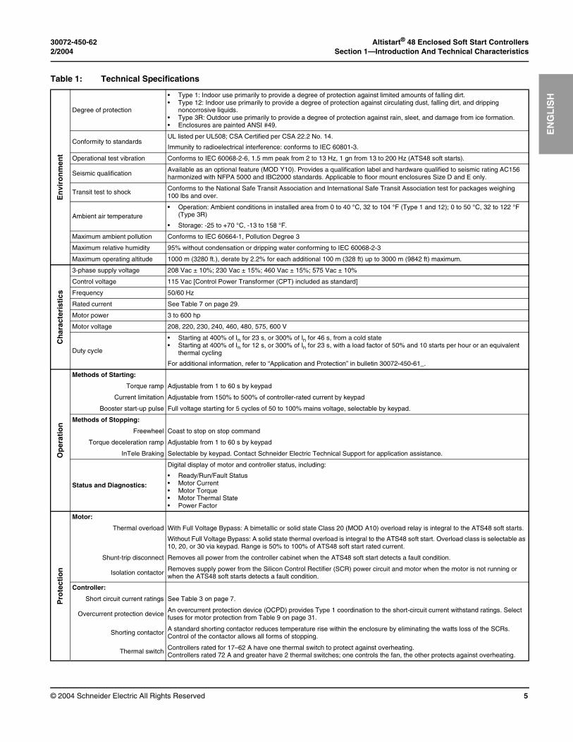
Table 1: Technical Specifications
En
viro
nm
ent
Degree of protection
• Type 1: Indoor use primarily to provide a degree of protection against limited amounts of falling dirt.• Type 12: Indoor use primarily to provide a degree of protection against circulating dust, falling dirt, and dripping
noncorrosive liquids.• Type 3R: Outdoor use primarily to provide a degree of protection against rain, sleet, and damage from ice formation.• Enclosures are painted ANSI #49.
Conformity to standardsUL listed per UL508; CSA Certified per CSA 22.2 No. 14.
Immunity to radioelectrical interference: conforms to IEC 60801-3.
Operational test vibration Conforms to IEC 60068-2-6, 1.5 mm peak from 2 to 13 Hz, 1 gn from 13 to 200 Hz (ATS48 soft starts).
Seismic qualificationAvailable as an optional feature (MOD Y10). Provides a qualification label and hardware qualified to seismic rating AC156 harmonized with NFPA 5000 and IBC2000 standards. Applicable to floor mount enclosures Size D and E only.
Transit test to shock Conforms to the National Safe Transit Association and International Safe Transit Association test for packages weighing 100 lbs and over.
Ambient air temperature• Operation: Ambient conditions in installed area from 0 to 40 °C, 32 to 104 °F (Type 1 and 12); 0 to 50 °C, 32 to 122 °F
(Type 3R)
• Storage: -25 to +70 °C, -13 to 158 °F.
Maximum ambient pollution Conforms to IEC 60664-1, Pollution Degree 3
Maximum relative humidity 95% without condensation or dripping water conforming to IEC 60068-2-3
Maximum operating altitude 1000 m (3280 ft.), derate by 2.2% for each additional 100 m (328 ft) up to 3000 m (9842 ft) maximum.
Ch
arac
teri
stic
s
3-phase supply voltage 208 Vac ± 10%; 230 Vac ± 15%; 460 Vac ± 15%; 575 Vac ± 10%
Control voltage 115 Vac [Control Power Transformer (CPT) included as standard]
Frequency 50/60 Hz
Rated current See Table 7 on page 29.
Motor power 3 to 600 hp
Motor voltage 208, 220, 230, 240, 460, 480, 575, 600 V
Duty cycle
• Starting at 400% of In for 23 s, or 300% of In for 46 s, from a cold state• Starting at 400% of In for 12 s, or 300% of In for 23 s, with a load factor of 50% and 10 starts per hour or an equivalent
thermal cycling
For additional information, refer to “Application and Protection” in bulletin 30072-450-61_.
Op
erat
ion
Methods of Starting:
Torque ramp Adjustable from 1 to 60 s by keypad
Current limitation Adjustable from 150% to 500% of controller-rated current by keypad
Booster start-up pulse Full voltage starting for 5 cycles of 50 to 100% mains voltage, selectable by keypad.
Methods of Stopping:
Freewheel Coast to stop on stop command
Torque deceleration ramp Adjustable from 1 to 60 s by keypad
InTele Braking Selectable by keypad. Contact Schneider Electric Technical Support for application assistance.
Status and Diagnostics:
Digital display of motor and controller status, including:
• Ready/Run/Fault Status• Motor Current• Motor Torque• Motor Thermal State• Power Factor
Pro
tect
ion
Motor:
Thermal overload With Full Voltage Bypass: A bimetallic or solid state Class 20 (MOD A10) overload relay is integral to the ATS48 soft starts.
Without Full Voltage Bypass: A solid state thermal overload is integral to the ATS48 soft start. Overload class is selectable as 10, 20, or 30 via keypad. Range is 50% to 100% of ATS48 soft start rated current.
Shunt-trip disconnect Removes all power from the controller cabinet when the ATS48 soft start detects a fault condition.
Isolation contactor Removes supply power from the Silicon Control Rectifier (SCR) power circuit and motor when the motor is not running or when the ATS48 soft starts detects a fault condition.
Controller:
Short circuit current ratings See Table 3 on page 7.
Overcurrent protection deviceAn overcurrent protection device (OCPD) provides Type 1 coordination to the short-circuit current withstand ratings. Select fuses for motor protection from Table 9 on page 31.
Shorting contactor A standard shorting contactor reduces temperature rise within the enclosure by eliminating the watts loss of the SCRs. Control of the contactor allows all forms of stopping.
Thermal switch Controllers rated for 17–62 A have one thermal switch to protect against overheating. Controllers rated 72 A and greater have 2 thermal switches; one controls the fan, the other protects against overheating.
Altistart® 48 Enclosed Soft Start Controllers 30072-450-62Section 1—Introduction And Technical Characteristics 2/2004
© 2004 Schneider Electric All Rights Reserved6
EN
GL
ISH
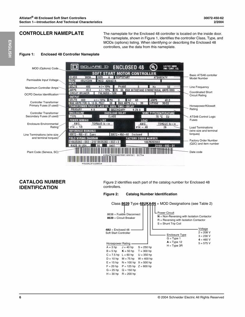
CONTROLLER NAMEPLATE The nameplate for the Enclosed 48 controller is located on the inside door. This nameplate, shown in Figure 1, identifies the controller Class, Type, and MODs (options) listing. When identifying or describing the Enclosed 48 controllers, use the data from this nameplate.
CATALOG NUMBER IDENTIFICATION
Figure 2 identifies each part of the catalog number for Enclosed 48 controllers.
Figure 1: Enclosed 48 Controller Nameplate
MOD (Options) Code
Permissible Input Voltage
Maximum Controller Amps
Controller TransformerPrimary Fuses (if used)
Basic ATS48 contollerModel Number
Horsepower/Kilowatt Rating
Line Frequency
OCPD Device IdentificationCoordinated Short Circuit Rating
ATS48 Control Logic Fuses
Controller TransformerSecondary Fuses (if used)
Load Terminations (wire size and terminal torques)
Factory Order Number(Q2C) and item number
Date codePlant Code (Seneca, SC)
Line Terminations (wire sizeand terminal torques)
Enclosure EnvironmentalRating
Figure 2: Catalog Number Identification
Class 8639 Type 48UKA4N + MOD Designations (see Table 2)
8638 = Fusible Disconnect8639 = Circuit Breaker
48U = Enclosed 48Soft Start Controller
Horsepower RatingA = 3 hp J = 40 hp S = 250 hpB = 5 hp K = 50 hp T = 300 hpC = 7.5 hp L = 60 hp U = 350 hpD = 10 hp M = 75 hp W = 400 hpE = 15 hp N = 100 hp X = 500 hpF = 20 hp P = 125 hp Z = 600 hpG = 25 hp Q = 150 hpH = 30 hp R = 200 hp
Enclosure TypeG = Type 1A = Type 12H = Type 3R
Voltage2 = 208 V3 = 230 V4 = 460 V5 = 575 V
Power CircuitN = Non-Reversing with Isolation ContactorR = Reversing with Isolation ContactorS = Shunt Trip Coil
30072-450-62 Altistart® 48 Enclosed Soft Start Controllers2/2004 Section 1—Introduction And Technical Characteristics
© 2004 Schneider Electric All Rights Reserved 7
EN
GL
ISH
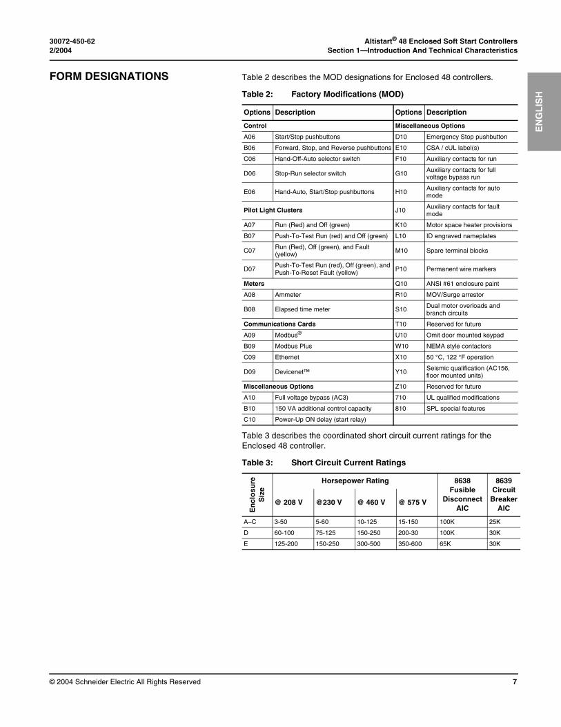
FORM DESIGNATIONS Table 2 describes the MOD designations for Enclosed 48 controllers.
Table 3 describes the coordinated short circuit current ratings for the Enclosed 48 controller.
Table 2: Factory Modifications (MOD)
Options Description Options Description
Control Miscellaneous Options
A06 Start/Stop pushbuttons D10 Emergency Stop pushbutton
B06 Forward, Stop, and Reverse pushbuttons E10 CSA / cUL label(s)
C06 Hand-Off-Auto selector switch F10 Auxiliary contacts for run
D06 Stop-Run selector switch G10 Auxiliary contacts for full voltage bypass run
E06 Hand-Auto, Start/Stop pushbuttons H10Auxiliary contacts for auto mode
Pilot Light Clusters J10 Auxiliary contacts for fault mode
A07 Run (Red) and Off (green) K10 Motor space heater provisions
B07 Push-To-Test Run (red) and Off (green) L10 ID engraved nameplates
C07 Run (Red), Off (green), and Fault (yellow) M10 Spare terminal blocks
D07Push-To-Test Run (red), Off (green), and Push-To-Reset Fault (yellow) P10 Permanent wire markers
Meters Q10 ANSI #61 enclosure paint
A08 Ammeter R10 MOV/Surge arrestor
B08 Elapsed time meter S10 Dual motor overloads and branch circuits
Communications Cards T10 Reserved for future
A09 Modbus® U10 Omit door mounted keypad
B09 Modbus Plus W10 NEMA style contactors
C09 Ethernet X10 50 °C, 122 °F operation
D09 Devicenet™ Y10 Seismic qualification (AC156, floor mounted units)
Miscellaneous Options Z10 Reserved for future
A10 Full voltage bypass (AC3) 710 UL qualified modifications
B10 150 VA additional control capacity 810 SPL special features
C10 Power-Up ON delay (start relay)
Table 3: Short Circuit Current Ratings
En
clo
sure
Siz
e
Horsepower Rating 8638Fusible
DisconnectAIC
8639 Circuit
BreakerAIC
@ 208 V @230 V @ 460 V @ 575 V
A–C 3-50 5-60 10-125 15-150 100K 25K
D 60-100 75-125 150-250 200-30 100K 30K
E 125-200 150-250 300-500 350-600 65K 30K

Altistart® 48 Enclosed Soft Start Controllers 30072-450-62Section 1—Introduction And Technical Characteristics 2/2004
© 2004 Schneider Electric All Rights Reserved8
EN
GL
ISH
30072-450-62 Altistart® 48 Enclosed Soft Start Controllers2/2004 Section 2—Receiving, Handling, and Storage
© 2004 Schneider Electric All Rights Reserved 9
EN
GL
ISH
SECTION 2— RECEIVING, HANDLING, AND STORAGE
RECEIVING AND PRELIMINARY INSPECTION
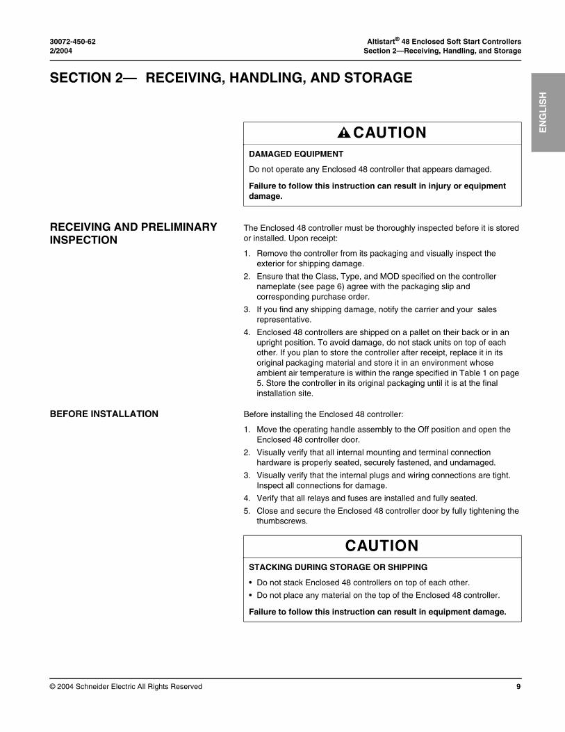
The Enclosed 48 controller must be thoroughly inspected before it is stored or installed. Upon receipt:
1. Remove the controller from its packaging and visually inspect the exterior for shipping damage.
2. Ensure that the Class, Type, and MOD specified on the controller nameplate (see page 6) agree with the packaging slip and corresponding purchase order.
3. If you find any shipping damage, notify the carrier and your sales representative.
4. Enclosed 48 controllers are shipped on a pallet on their back or in an upright position. To avoid damage, do not stack units on top of each other. If you plan to store the controller after receipt, replace it in its original packaging material and store it in an environment whose ambient air temperature is within the range specified in Table 1 on page 5. Store the controller in its original packaging until it is at the final installation site.
BEFORE INSTALLATION Before installing the Enclosed 48 controller:
1. Move the operating handle assembly to the Off position and open the Enclosed 48 controller door.
2. Visually verify that all internal mounting and terminal connection hardware is properly seated, securely fastened, and undamaged.
3. Visually verify that the internal plugs and wiring connections are tight. Inspect all connections for damage.
4. Verify that all relays and fuses are installed and fully seated.
5. Close and secure the Enclosed 48 controller door by fully tightening the thumbscrews.
CAUTIONDAMAGED EQUIPMENT
Do not operate any Enclosed 48 controller that appears damaged.
Failure to follow this instruction can result in injury or equipment damage.
CAUTIONSTACKING DURING STORAGE OR SHIPPING
• Do not stack Enclosed 48 controllers on top of each other.
• Do not place any material on the top of the Enclosed 48 controller.
Failure to follow this instruction can result in equipment damage.
Altistart® 48 Enclosed Soft Start Controllers 30072-450-62Section 2—Receiving, Handling, and Storage 2/2004
© 2004 Schneider Electric All Rights Reserved10
EN
GL
ISH
HANDLING THE CONTROLLER
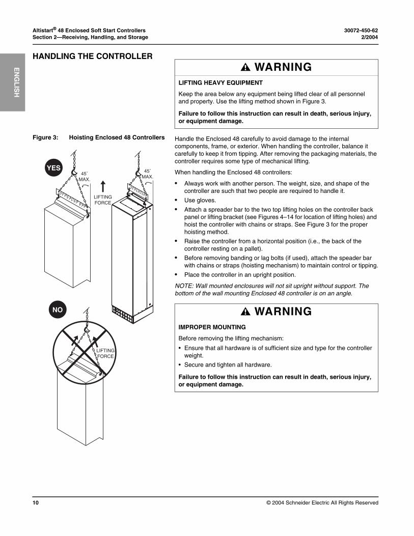
Handle the Enclosed 48 carefully to avoid damage to the internal components, frame, or exterior. When handling the controller, balance it carefully to keep it from tipping. After removing the packaging materials, the controller requires some type of mechanical lifting.
When handling the Enclosed 48 controllers:
• Always work with another person. The weight, size, and shape of the controller are such that two people are required to handle it.
• Use gloves.
• Attach a spreader bar to the two top lifting holes on the controller back panel or lifting bracket (see Figures 4–14 for location of lifting holes) and hoist the controller with chains or straps. See Figure 3 for the proper hoisting method.
• Raise the controller from a horizontal position (i.e., the back of the controller resting on a pallet).
• Before removing banding or lag bolts (if used), attach the speader bar with chains or straps (hoisting mechanism) to maintain control or tipping.
• Place the controller in an upright position.
NOTE: Wall mounted enclosures will not sit upright without support. The bottom of the wall mounting Enclosed 48 controller is on an angle.
WARNINGLIFTING HEAVY EQUIPMENT
Keep the area below any equipment being lifted clear of all personnel and property. Use the lifting method shown in Figure 3.
Failure to follow this instruction can result in death, serious injury, or equipment damage.
Figure 3: Hoisting Enclosed 48 Controllers
LIFTINGFORCE
YES
LIFTINGFORCE
NO
45˚MAX.
SPREADER BAR
SPREADER
45˚MAX.
WARNINGIMPROPER MOUNTING
Before removing the lifting mechanism:
• Ensure that all hardware is of sufficient size and type for the controller weight.
• Secure and tighten all hardware.
Failure to follow this instruction can result in death, serious injury, or equipment damage.

30072-450-62 Altistart® 48 Enclosed Soft Start Controllers2/2004 Section 3—Installation
© 2004 Schneider Electric All Rights Reserved 11
EN
GL
ISH
SECTION 3— INSTALLATION
PRECAUTIONS Read, understand, and follow all precautions described in this instruction bulletin and in the reference documents listed on page 3 before attempting to install, service, or maintain the Enclosed 48 controller.
Follow these precautions when installing Enclosed 48 controllers:
• The Enclosed 48 controller can be installed in a Pollution Degree 3 environment, as defined in NEMA ICS1-111A and IEC 60664-1. Ensure that the expected environment is compatible with this rating.
• When attaching wall mounted and free standing controllers, use fasteners rated for the weight of the apparatus, the expected shock and vibration of the installation, and the expected environment.
• During installation and operation, maintain the ventilation clearances specified on the factory supplied outline dimension drawing(s) or in Figures 4–14. Provide sufficient cooling for the heat load.
• Do not mount the controller in direct sunlight or on hot surfaces (Type 1 and 12 only). Mount it on a solid, flat surface only. When drilling for conduit entry, take care to prevent metal chips from falling on parts and electronic printed wiring boards.
DANGERHAZARD OF ELECTRIC SHOCK, EXPLOSION, OR ARC FLASH
• Apply appropriate personal protective equipment (PPE) and follow safe electrical work practices. See NFPA 70E.
• This equipment must be installed and serviced only by qualified electrical personnel.
• Turn OFF all power supplying this equipment before working on or inside the equipment.
• Always use a properly rated voltage sensing device to confirm that all power is off.
• Replace all devices, doors, and covers before turning on the power to this equipment.
Failure to follow these instructions will result in death or serious injury.
Altistart® 48 Enclosed Soft Start Controllers 30072-450-62Section 3—Installation 2/2004
© 2004 Schneider Electric All Rights Reserved12
EN
GL
ISH
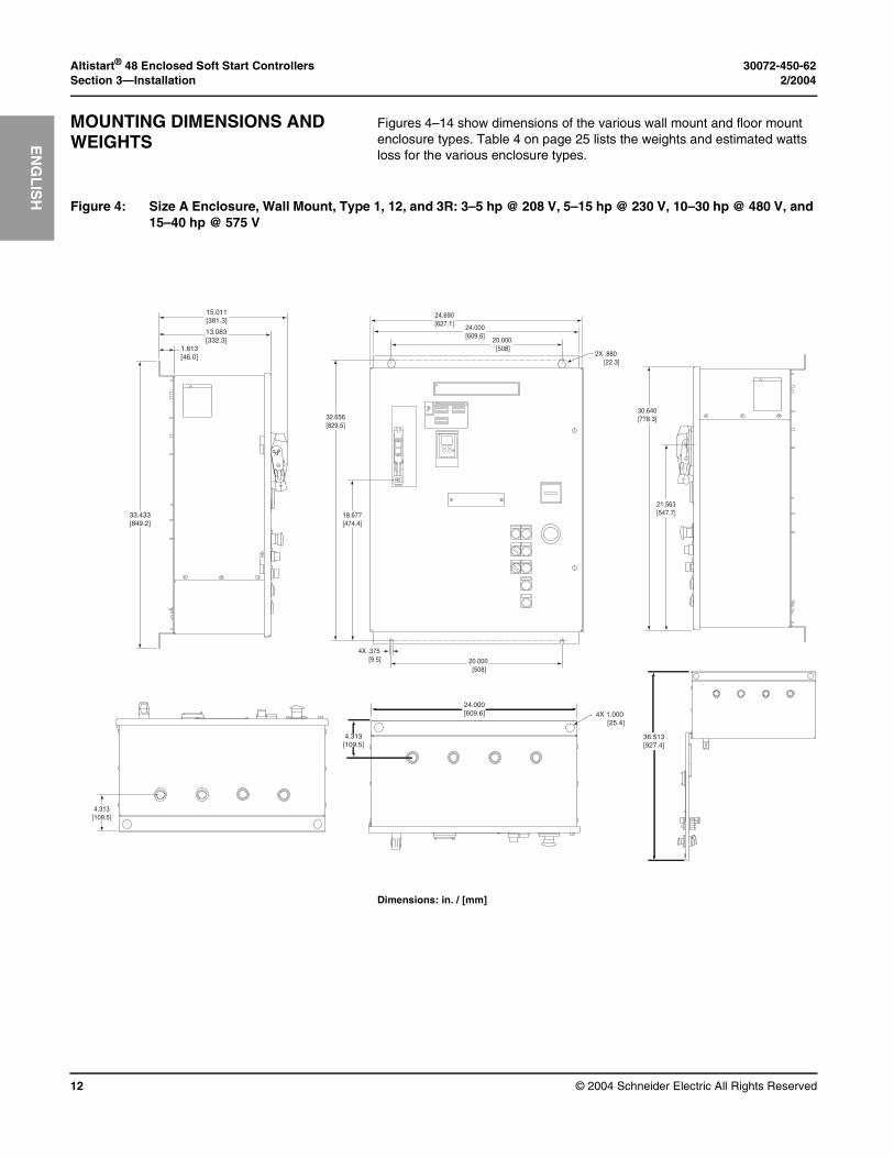
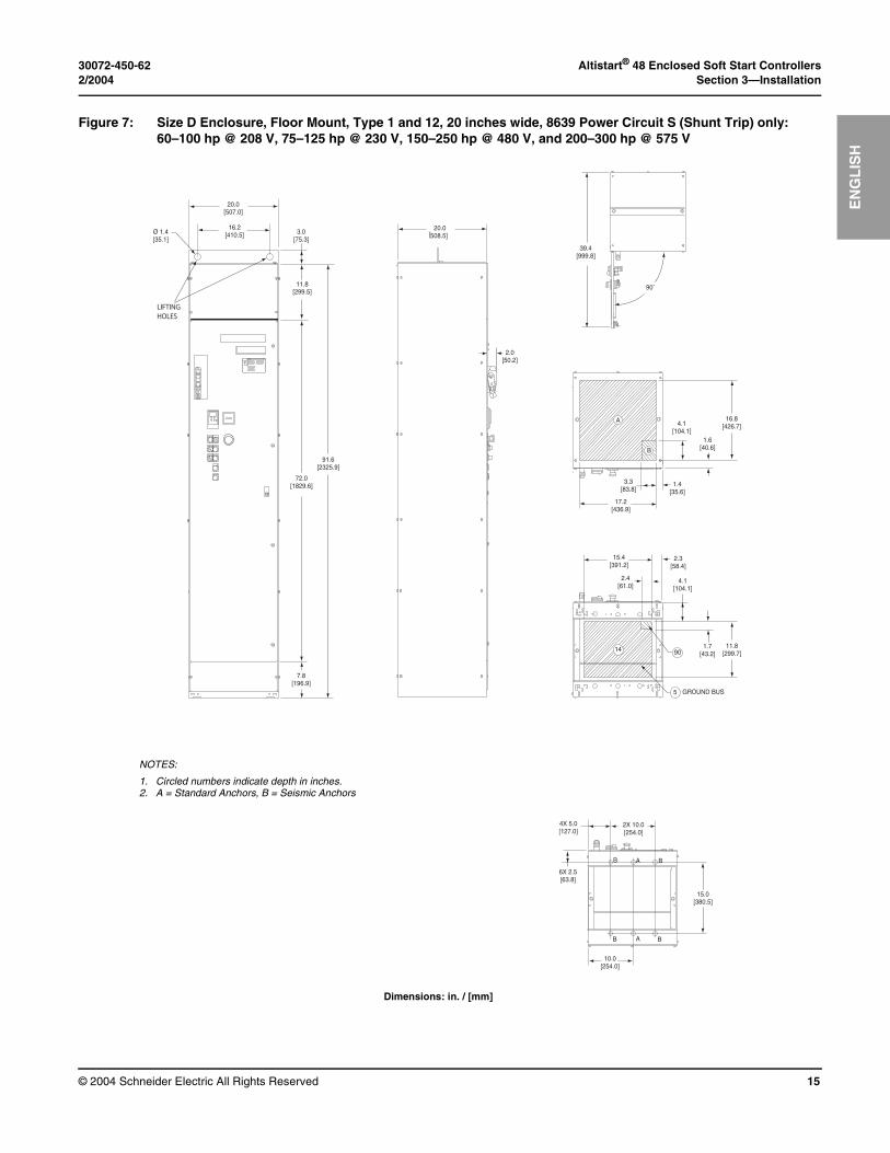
MOUNTING DIMENSIONS AND WEIGHTS
Figures 4–14 show dimensions of the various wall mount and floor mount enclosure types. Table 4 on page 25 lists the weights and estimated watts loss for the various enclosure types.
Dimensions: in. / [mm]
Figure 4: Size A Enclosure, Wall Mount, Type 1, 12, and 3R: 3–5 hp @ 208 V, 5–15 hp @ 230 V, 10–30 hp @ 480 V, and 15–40 hp @ 575 V
24.000[609.6]
4.313[109.5]
4X 1.000 [25.4]
36.513[927.4]
33.433[849.2]
1.813[46.0]
13.083[332.3]
15.011[381.3]
ON
OFF
TRIP
24.690[627.1] 24.000
[609.6]20.000 [508]
32.656[829.5]
18.677[474.4]
4X .375 [9.5] 20.000
[508]
2X .880 [22.3]
21.563[547.7]
30.640[778.3]
4.313[109.5]
30072-450-62 Altistart® 48 Enclosed Soft Start Controllers2/2004 Section 3—Installation
© 2004 Schneider Electric All Rights Reserved 13
EN
GL
ISH
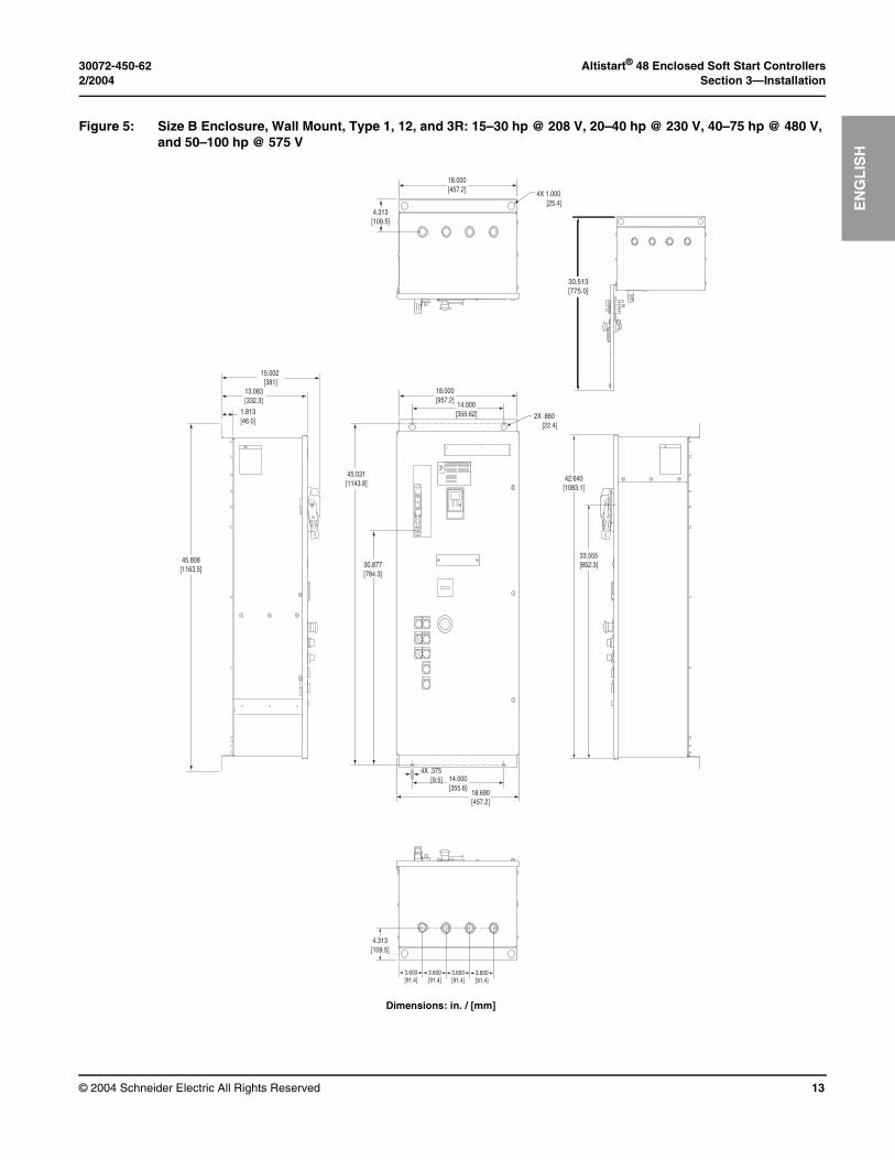
Dimensions: in. / [mm]
Figure 5: Size B Enclosure, Wall Mount, Type 1, 12, and 3R: 15–30 hp @ 208 V, 20–40 hp @ 230 V, 40–75 hp @ 480 V, and 50–100 hp @ 575 V
33.555[852.3]
42.640[1083.1]
30.513[775.0]
4.313[109.5]
3.600[91.4]
3.600[91.4]
3.600[91.4]
3.600[91.4]
ON
OFF
TRIP
4X .375 [9.5] 14.000
[355.6}18.690[457.2]
30.877[784.3]
45.031[1143.8]
14.000[355.62]
18.000[957.2]
2X .880 [22.4]
4.313[109.5]
18.000[457.2] 4X 1.000
[25.4]
15.002 [381]
13.083[332.3]
1.813[46.0]
45.808[1163.5]
Altistart® 48 Enclosed Soft Start Controllers 30072-450-62Section 3—Installation 2/2004
© 2004 Schneider Electric All Rights Reserved14
EN
GL
ISH
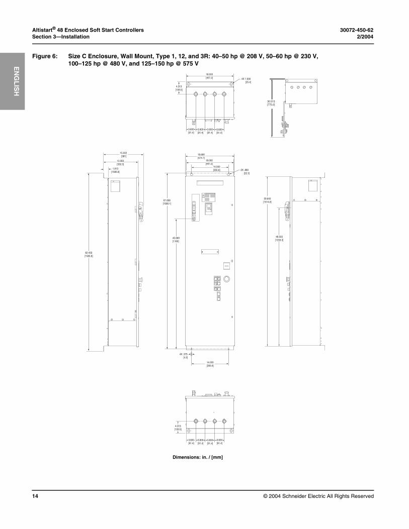
Dimensions: in. / [mm]
Figure 6: Size C Enclosure, Wall Mount, Type 1, 12, and 3R: 40–50 hp @ 208 V, 50–60 hp @ 230 V, 100–125 hp @ 480 V, and 125–150 hp @ 575 V
4.313[109.5]
18.000[457.2] 4X 1.000
[25.4]
3.600[91.4]
3.600[91.4]
3.600[91.4]
3.600[91.4]
30.513[775.0]
4.313[109.5]
3.600[91.4]
3.600[91.4]
3.600[91.4]
3.600[91.4]
ON
OFF
TRIP
4X .375 [4.5]
14.000[355.6]
45.669[1160]
61.656[1566.1]
14.000[355.6]
18.000[457.2]
2X .880 [22.3]
18.690[474.7]
48.555[1233.3]
59.640[1514.9]
15.002 [381]
13.083[332.3]
1.813[1585.8]
62.433[1585.8]
30072-450-62 Altistart® 48 Enclosed Soft Start Controllers2/2004 Section 3—Installation
© 2004 Schneider Electric All Rights Reserved 15
EN
GL
ISH
Dimensions: in. / [mm]
Figure 7: Size D Enclosure, Floor Mount, Type 1 and 12, 20 inches wide, 8639 Power Circuit S (Shunt Trip) only: 60–100 hp @ 208 V, 75–125 hp @ 230 V, 150–250 hp @ 480 V, and 200–300 hp @ 575 V
ON
OFF
TRIP
Ø 1.4[35.1]
20.0[507.0]
16.2[410.5] 3.0
[75.3]
11.8[299.5]
72.0[1829.6]
91.6[2325.9]
7.8[196.9]
20.0508.5]
2.0[50.2]
[
A
B
4.1[104.1]
16.8[426.7]
1.6[40.6]
3.3[83.8]
17.2[436.9]
1.4[35.6]
39.4[999.8]
90˚
14 90
5
15.4[391.2]
2.4[61.0]
2.3[58.4]
4.1[104.1]
1.7[43.2]
11.8[299.7]
GROUND BUS
B A B
B A B
4X 5.0[127.0]
2X 10.0[254.0]
6X 2.5[63.8]
15.0[380.5]
10.0[254.0]
LIFTINGHOLES
NOTES:
1. Circled numbers indicate depth in inches.2. A = Standard Anchors, B = Seismic Anchors
Altistart® 48 Enclosed Soft Start Controllers 30072-450-62Section 3—Installation 2/2004
© 2004 Schneider Electric All Rights Reserved16
EN
GL
ISH
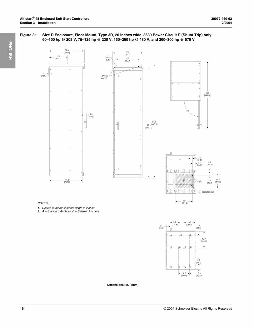
Dimensions: in. / [mm]
Figure 8: Size D Enclosure, Floor Mount, Type 3R, 20 inches wide, 8639 Power Circuit S (Shunt Trip) only: 60–100 hp @ 208 V, 75–125 hp @ 230 V, 150–250 hp @ 480 V, and 200–300 hp @ 575 V
32.6[829.1]
17.2[437.1]
.5[12.8]
30.2[767.5]
2.4[59.9]
Ø 1.4[35.1]
27.7[703.1]
22.2[563.9]
LIFTINGHOLES
94.8[2407.0]92.9
[2360.7]
14
5
90
GROUND BUS
15.4[391.2]
1.7[43.2]
11.8[299.7]
2.4[61.0]2.3
[58.4]4.1
[104.1]
3.4[86.1]
8.9[224.9]
10.0[254.0] 3.7
[94.3]
13.9[353.3]
2.7[68.2]
5.0[127.0]
10.0[254.0]
B B B
B B B
B B B
A
A
90˚
56.3[1431.0]
NOTES:
1. Circled numbers indicate depth in inches.2. A = Standard Anchors, B = Seismic Anchors
30072-450-62 Altistart® 48 Enclosed Soft Start Controllers2/2004 Section 3—Installation
© 2004 Schneider Electric All Rights Reserved 17
EN
GL
ISH
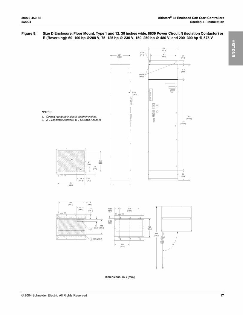
Dimensions: in. / [mm]
Figure 9: Size D Enclosure, Floor Mount, Type 1 and 12, 30 inches wide, 8639 Power Circuit N (Isolation Contactor) or R (Reversing): 60–100 hp @208 V, 75–125 hp @ 230 V, 150–250 hp @ 480 V, and 200–300 hp @ 575 V
49.4[1254.2]
90˚
27.2[690.9]
8.3[210.8]
4.1[104.1]
16.8[426.7]
1.6[40.6]
1.4[35.6]
A
B
B A B
B A B
4X 5.0[127.0]
20.0[508.0]
6X 2.5[63.8]
15.0[380.5]
15.0[381.0]
90
5
25.4[645.2]
7.4[188.0]
2.3[58.4]
4.1[104.1]
1.7[43.2]
11.8[299.7]
GROUND BUS
14
20.1509.5]
2.0[50.2]
[
ON
OFF
TRIP
Ø 1.4[35.1]
30.0[761.0]
26.2[664.5] 3.0
[75.3]
11.8[299.5]
LIFTINGHOLES
72.0[1829.6]
91.6[2325.9]
7.8[196.9]
NOTES:
1. Circled numbers indicate depth in inches.2. A = Standard Anchors, B = Seismic Anchors
Altistart® 48 Enclosed Soft Start Controllers 30072-450-62Section 3—Installation 2/2004
© 2004 Schneider Electric All Rights Reserved18
EN
GL
ISH
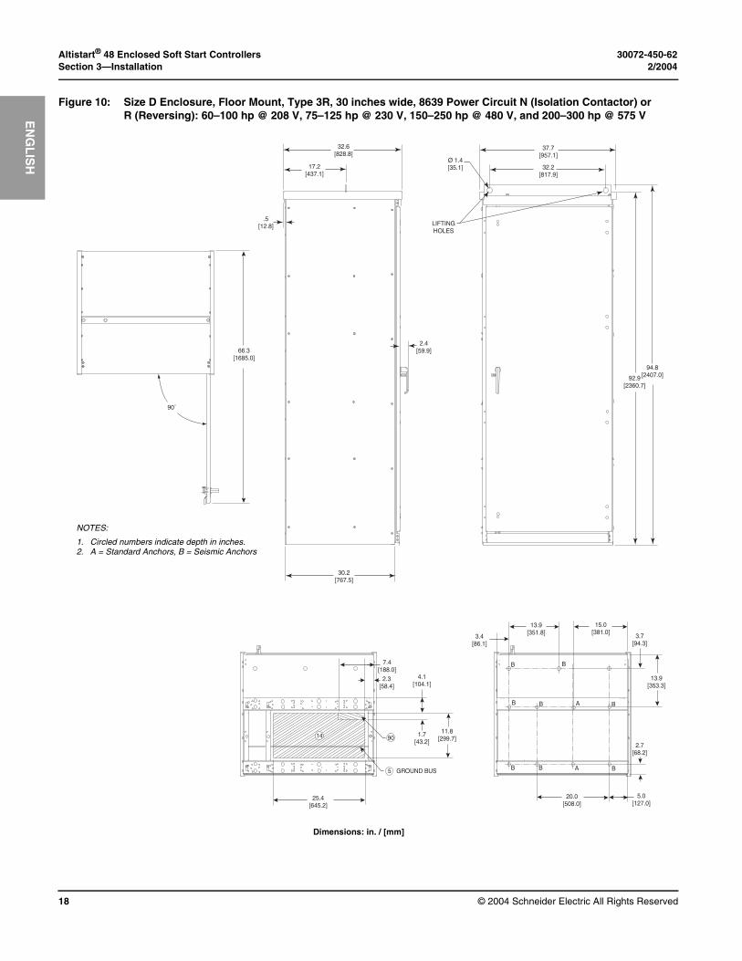
Dimensions: in. / [mm]
Figure 10: Size D Enclosure, Floor Mount, Type 3R, 30 inches wide, 8639 Power Circuit N (Isolation Contactor) or R (Reversing): 60–100 hp @ 208 V, 75–125 hp @ 230 V, 150–250 hp @ 480 V, and 200–300 hp @ 575 V
32.6[828.8]
17.2[437.1]
.5[12.8]
30.2[767.5]
2.4[59.9]
Ø 1.4[35.1]
37.7[957.1]
32.2[817.9]
LIFTINGHOLES
94.8[2407.0]92.9
[2360.7]
90˚
66.3[1685.0]
14
5
90
GROUND BUS
25.4[645.2]
1.7[43.2]
11.8[299.7]
7.4[188.0]
2.3[58.4]
4.1[104.1]
3.4[86.1]
13.9[351.8]
15.0[381.0]
3.7[94.3]
13.9[353.3]
2.7[68.2]
5.0[127.0]
20.0[508.0]
B B
B B B
B B BA
A
NOTES:
1. Circled numbers indicate depth in inches.2. A = Standard Anchors, B = Seismic Anchors

30072-450-62 Altistart® 48 Enclosed Soft Start Controllers2/2004 Section 3—Installation
© 2004 Schneider Electric All Rights Reserved 19
EN
GL
ISH
Dimensions: in. / [mm]
Figure 11: Size E Enclosure, Floor Mount, Type 1 and 12, 35 inches wide, 8638 and 8639 Power Circuit N (Isolation Contactor) or S (Shunt Trip): 125–200 hp @ 208 V, 150–250 hp @ 230 V, 300–500 hp @ 480 V, and 350–600 hp @ 575 V
54.4[1381.2]
90˚
32.2[817.9]
8.3[210.8]
2.0[50.8]
16.8[426.7]
1.6[40.6]
1.4[35.6]
A
B
90
5
30.4[772.2]
7.6[193.0]
2.3[58.4]
4.1[104.1]
1.3[33.0]
11.8[299.7]14
B A B
B A B
4X 5.0[127.0]
25.0[635.0]
6X 2.5[63.8]
15.0[380.5]
17.5[444.5]
20.0[508.5]
2.0[50.2]
ON
OFF
TRIP
35.0[889.0]
31.2[791.5]
Ø 1.4[35.1]
LIFTINGHOLES
3.0[75.3]
11.8[299.5]
72.0[1829.6]
91.62325.9]
7.8[196.9]
NOTES:
1. Circled numbers indicate depth in inches.2. A = Standard Anchors, B = Seismic Anchors
Altistart® 48 Enclosed Soft Start Controllers 30072-450-62Section 3—Installation 2/2004
© 2004 Schneider Electric All Rights Reserved20
EN
GL
ISH
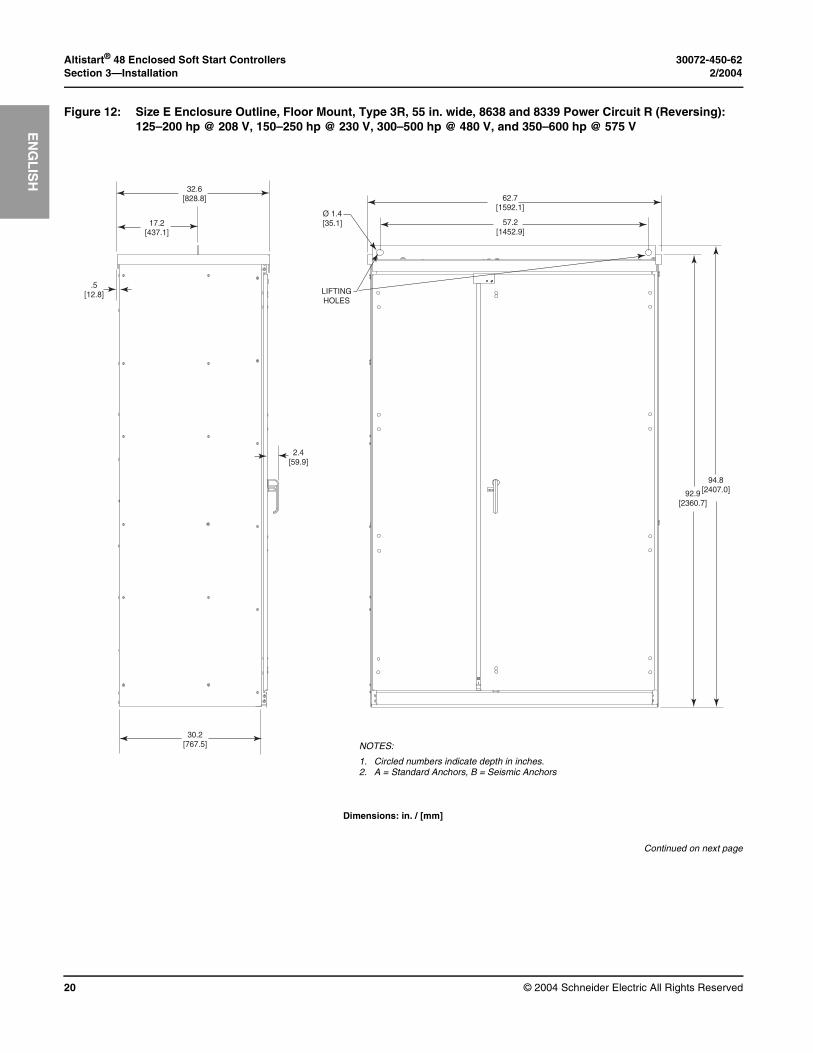
Dimensions: in. / [mm]
Continued on next page
Figure 12: Size E Enclosure Outline, Floor Mount, Type 3R, 55 in. wide, 8638 and 8339 Power Circuit R (Reversing): 125–200 hp @ 208 V, 150–250 hp @ 230 V, 300–500 hp @ 480 V, and 350–600 hp @ 575 V
32.6[828.8]
17.2[437.1]
.5[12.8]
30.2[767.5]
2.4[59.9]
62.7[1592.1]
57.2[1452.9]
94.8[2407.0]92.9
[2360.7]
Ø 1.4[35.1]
LIFTINGHOLES
NOTES:
1. Circled numbers indicate depth in inches.2. A = Standard Anchors, B = Seismic Anchors
30072-450-62 Altistart® 48 Enclosed Soft Start Controllers2/2004 Section 3—Installation
© 2004 Schneider Electric All Rights Reserved 21
EN
GL
ISH
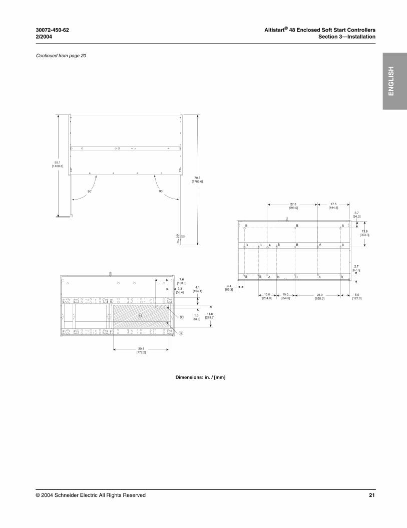
Dimensions: in. / [mm]
Continued from page 20
90˚
70.3[1786.0]
55.1[1400.3]
90˚
14
5
90
30.4[772.2]
1.3[33.0]
11.8[299.7]
7.6[193.0]
2.3[58.4]
4.1[104.1]
17.5[444.5]
3.7[94.3]
13.9[353.3]
2.7[67.5]
5.0[127.0]
25.0[635.0]
B
B B B
B B BA
A
B
3.4[86.3]
B
B
A
A B
B
B
10.0[254.0]
10.0[254.0]
27.5[698.5]
Altistart® 48 Enclosed Soft Start Controllers 30072-450-62Section 3—Installation 2/2004
© 2004 Schneider Electric All Rights Reserved22
EN
GL
ISH
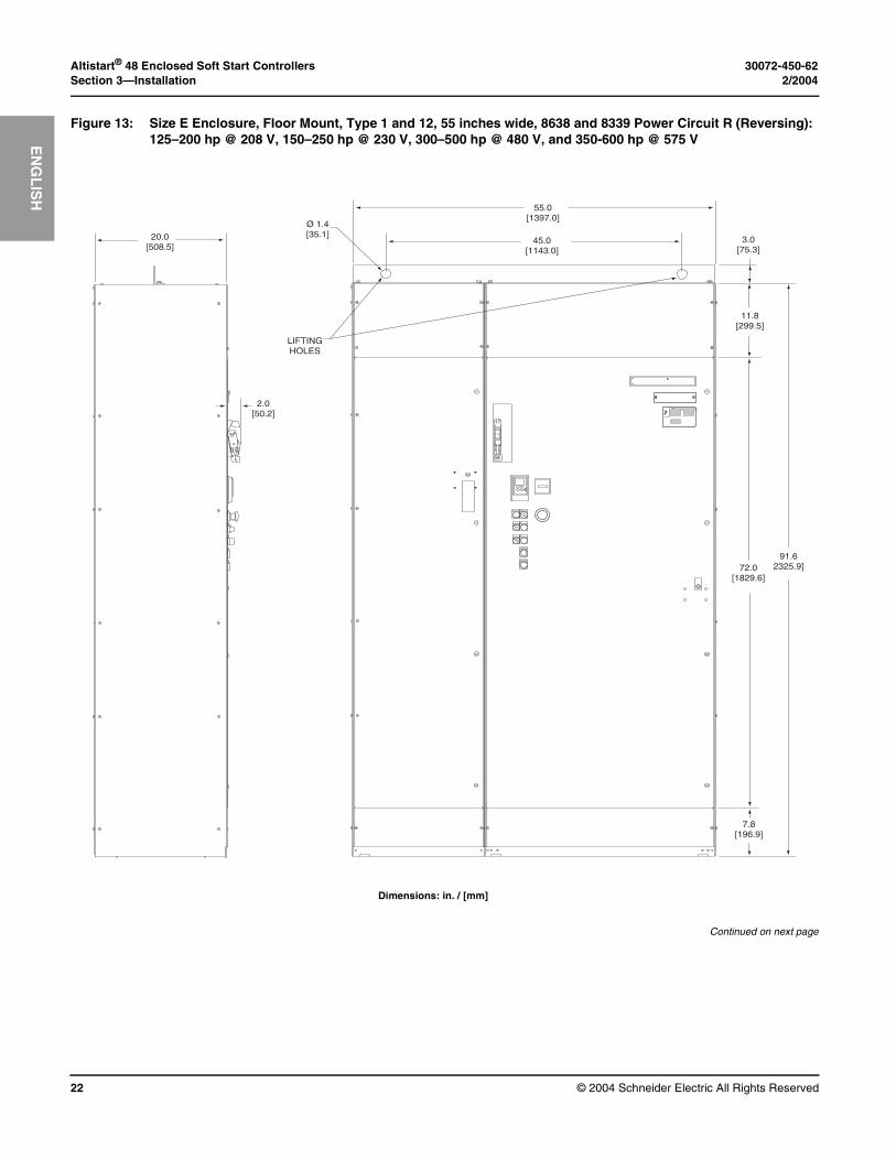
Dimensions: in. / [mm]
Continued on next page
Figure 13: Size E Enclosure, Floor Mount, Type 1 and 12, 55 inches wide, 8638 and 8339 Power Circuit R (Reversing): 125–200 hp @ 208 V, 150–250 hp @ 230 V, 300–500 hp @ 480 V, and 350-600 hp @ 575 V
20.0[508.5]
2.0[50.2]
ON
OFF
TRIP
55.0[1397.0]
45.0[1143.0]
Ø 1.4[35.1]
LIFTINGHOLES
3.0[75.3]
11.8[299.5]
72.0[1829.6]
91.62325.9]
7.8[196.9]
30072-450-62 Altistart® 48 Enclosed Soft Start Controllers2/2004 Section 3—Installation
© 2004 Schneider Electric All Rights Reserved 23
EN
GL
ISH
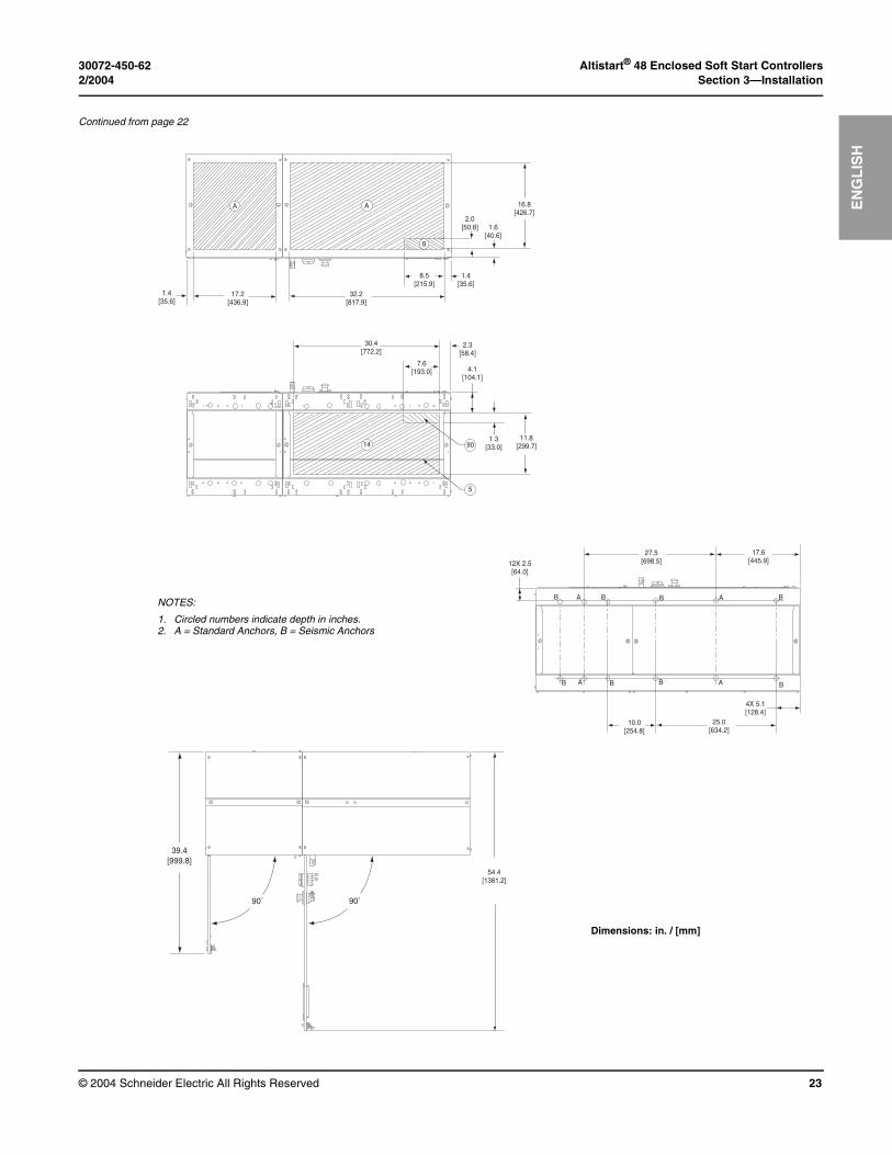
Continued from page 22
B A B
B A B
27.5[698.5]12X 2.5
[64.0]
10.0[254.8]
B B
B BA
A
17.6[445.9]
25.0[634.2]
4X 5.1[128.4]
54.4[1381.2]
39.4[999.8]
90˚ 90˚
32.2[817.9]
8.5[215.9]
2.0[50.8]
16.8[426.7]
1.6[40.6]
1.4[35.6]
A
B
90
5
30.4[772.2]
7.6[193.0]
2.3[58.4]
4.1[104.1]
1.3[33.0]
11.8[299.7]14
A
1.4[35.6]
17.2[436.9]
NOTES:
1. Circled numbers indicate depth in inches.2. A = Standard Anchors, B = Seismic Anchors
Dimensions: in. / [mm]
Altistart® 48 Enclosed Soft Start Controllers 30072-450-62Section 3—Installation 2/2004
© 2004 Schneider Electric All Rights Reserved24
EN
GL
ISH
Dimensions: in. / [mm]
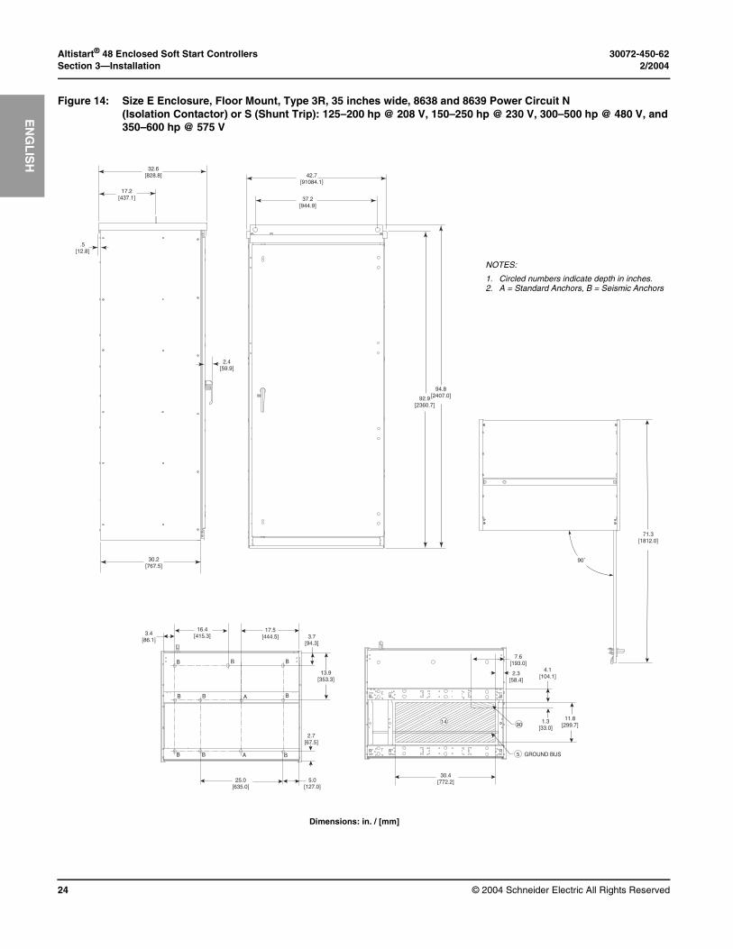
Figure 14: Size E Enclosure, Floor Mount, Type 3R, 35 inches wide, 8638 and 8639 Power Circuit N(Isolation Contactor) or S (Shunt Trip): 125–200 hp @ 208 V, 150–250 hp @ 230 V, 300–500 hp @ 480 V, and350–600 hp @ 575 V
32.6[828.8]
17.2[437.1]
.5[12.8]
30.2[767.5]
2.4[59.9]
42.7[91084.1]
37.2[944.9]
94.8[2407.0]92.9
[2360.7]
90˚
71.3[1812.0]
14
5
90
GROUND BUS
30.4[772.2]
1.3[33.0]
11.8[299.7]
7.6[193.0]
2.3[58.4]
4.1[104.1]
3.4[86.1]
16.4[415.3]
17.5[444.5] 3.7
[94.3]
13.9[353.3]
2.7[67.5]
5.0[127.0]
25.0[635.0]
B B
B B B
B B BA
A
B
NOTES:
1. Circled numbers indicate depth in inches.2. A = Standard Anchors, B = Seismic Anchors
30072-450-62 Altistart® 48 Enclosed Soft Start Controllers2/2004 Section 3—Installation
© 2004 Schneider Electric All Rights Reserved 25
EN
GL
ISH
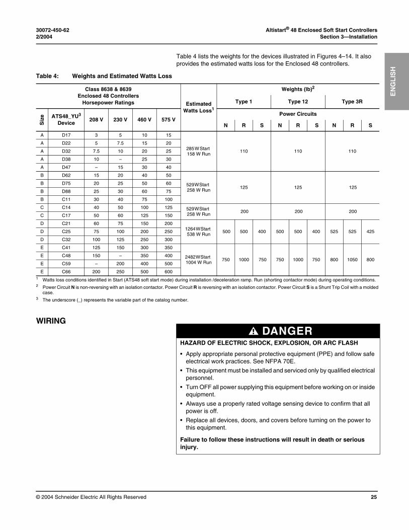
Table 4 lists the weights for the devices illustrated in Figures 4–14. It also provides the estimated watts loss for the Enclosed 48 controllers.
WIRING
Table 4: Weights and Estimated Watts Loss
Class 8638 & 8639Enclosed 48 Controllers
Horsepower Ratings Estimated Watts Loss1
Weights (lb)2
Type 1 Type 12 Type 3R
Siz
e ATS48_YU3 Device
208 V 230 V 460 V 575 VPower Circuits
N R S N R S N R S
A D17 3 5 10 15
285 W Start 158 W Run
110 110 110
A D22 5 7.5 15 20
A D32 7.5 10 20 25
A D38 10 – 25 30
A D47 – 15 30 40
B D62 15 20 40 50
529 W Start 258 W Run
125 125 125B D75 20 25 50 60
B D88 25 30 60 75
B C11 30 40 75 100
C C14 40 50 100 125 529 W Start 258 W Run
200 200 200C C17 50 60 125 150
D C21 60 75 150 2001264 W Start 538 W Run
500 500 400 500 500 400 525 525 425D C25 75 100 200 250
D C32 100 125 250 300
E C41 125 150 300 350
2482 W Start 1004 W Run
750 1000 750 750 1000 750 800 1050 800E C48 150 – 350 400
E C59 – 200 400 500
E C66 200 250 500 6001 Watts loss conditions identified in Start (ATS48 soft start mode) during installation /deceleration ramp. Run (shorting contactor mode) during operating conditions.2 Power Circuit N is non-reversing with an isolation contactor. Power Circuit R is reversing with an isolation contactor. Power Circuit S is a Shunt Trip Coil with a molded
case. 3 The underscore (_) represents the variable part of the catalog number.
DANGERHAZARD OF ELECTRIC SHOCK, EXPLOSION, OR ARC FLASH
• Apply appropriate personal protective equipment (PPE) and follow safe electrical work practices. See NFPA 70E.
• This equipment must be installed and serviced only by qualified electrical personnel.
• Turn OFF all power supplying this equipment before working on or inside equipment.
• Always use a properly rated voltage sensing device to confirm that all power is off.
• Replace all devices, doors, and covers before turning on the power to this equipment.
Failure to follow these instructions will result in death or serious injury.

Altistart® 48 Enclosed Soft Start Controllers 30072-450-62Section 3—Installation 2/2004
© 2004 Schneider Electric All Rights Reserved26
EN
GL
ISH
Control Wiring The customer terminal block pulls apart to facilitate control wiring. To access the control terminals, remove the top portion of the terminal block from the base by grasping it and pulling up. See Figure 15. Connect the control wiring to the top portion of the terminal block.
Each terminal is rated for one 16-12 AWG (1.3 to 3.3 mm2) wire or two 16 AWG (1.3 mm2) wires. Torque the terminal screws to 5 lb-in (0.6 N•m). The customer terminal block is designated TB1 on the wiring diagrams shipped with the Enclosed 48 controller.
NOTE: Depending on the power and control options ordered, several analog or digital inputs and outputs will be available at the control terminal blocks on the Altistart 48 soft start. For I/O availability, refer to the elementary diagram supplied with the Enclosed 48 controller. For I/O specifications and adjustments, refer to bulletin number 30072-450-61_.
Load Wiring The motor load connections to the Enclosed 48 controller terminate on the ATS48 soft start controller. The load terminals are designated T1, T2, and T3. Refer to the Enclosed 48 controller wiring diagrams, nameplate, and bulletin number 30072-450-61_, for load terminal wire and torque requirements.
Adaptation to Line Input This paragraph replaces the information described in the “Adaptation To Line Input” section of bulletin number 30072-450-61_. Each ATS48 soft start controller is factory configured for a particular line voltage as specified in the equipment order. The available ratings are: 208 Vac, 240 Vac, 480 Vac, and 600 Vac @ 60 Hz. The factory configured voltage rating is listed on the controller nameplate. Consult your Schneider Electric representative if the equipment requires modification from these voltage ratings.
The ATS48 soft start control transformer and OCPD may require change or reconfiguration.
Figure 15: Pull-Apart Customer Terminal Block
8998
-987
3

30072-450-62 Altistart® 48 Enclosed Soft Start Controllers2/2004 Section 4—Operation
© 2004 Schneider Electric All Rights Reserved 27
EN
GL
ISH
SECTION 4— OPERATION
NOTE: Before operating the Enclosed 48 controller, perform the procedures listed in “Factory Settings” on page 28.
For complete information about the operation of the ATS48 soft start, refer to bulletin number 30072-450-61_, and to the drawings supplied with the unit.
CIRCUIT DIAGRAMS The Enclosed 48 controller is an integrated package that can have different components and control schemes than those listed in bulletin number 30072-450-61_. Replace the “Recommended Wiring Diagrams” and “Recommended components Lists” sections of bulletin number 30072-450-61_ with the documentation shipped with the Enclosed 48 units. Wiring diagrams specific to Enclosed 48 controllers are shipped with each unit. For component information, refer to the replacement parts list beginning on page 37 of this document, or consult your Schneider Electric representative.
INTEGRATED FULL VOLTAGE BYPASS STARTER (MOD A10)
Enclosed 48 controllers can include an optional full-voltage bypass starter which provides the ability to bypass the ATS48 soft start and run the motor using across-the-line, full-voltage starting. This mode of operation can be used when the ATS48 soft start is out of service due to a protective fault but the process needs to continue until a convenient shutdown is possible. Ensure that the electrical and mechanical systems are compatible with full-voltage starting before using the bypass starter.
The bypass circuit includes a “Bypass-Norm” (Bypass/Normal) selector switch mounted on the controller, control logic, and a separate ambient-temperature compensated bimetallic or solid state overload relay (SSOLR). When the selector switch is in the Normal position, the ATS48 soft start controls the motor and the bypass contactor functions as a shorting contactor. The bypass contactor closes when the starting cycle is complete and opens when a stop command is given.
WARNINGUNINTENDED EQUIPMENT OPERATION
• Read and understand the Altistart 48 Y-Range Soft Start Controllers Installation Guide (30072-450-61_) before using the keypad display. Parameter changes affect drive controller operation. Most parameter changes require pressing ENT.
• Lock the keypad after making parameter adjustments.
• Do not reset soft start parameters to configurations other than those specified on the wiring diagrams supplied with the Enclosed 48 controller. Some factory-set drive parameters are critical for the Enclosed 48 controller power and control configurations.
• Do not alter the programming of factory-installed control devices or power contactors.
Failure to follow these instructions can result in death or serious injury.
Altistart® 48 Enclosed Soft Start Controllers 30072-450-62Section 4—Operation 2/2004
© 2004 Schneider Electric All Rights Reserved28
EN
GL
ISH
When the selector switch is in the Bypass position, the ATS48 soft start does not control the motor. The input contactor and the bypass contactor are directly opened and closed by customer-supplied control.
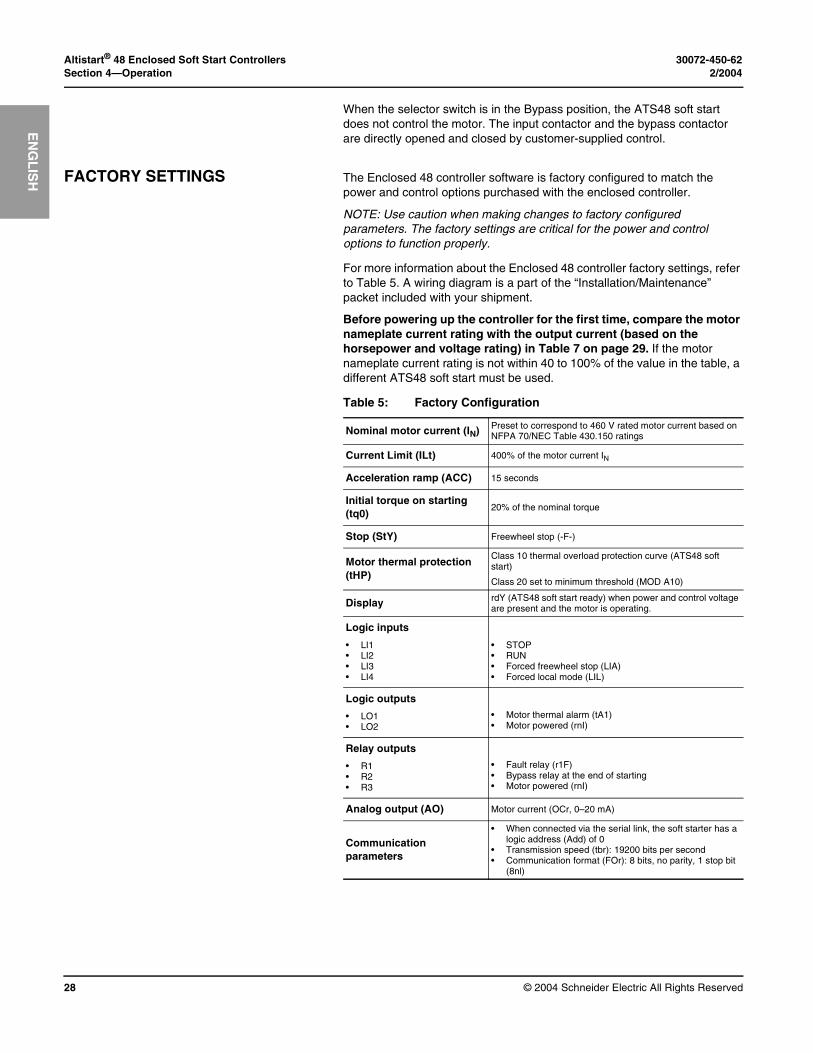
FACTORY SETTINGS The Enclosed 48 controller software is factory configured to match the power and control options purchased with the enclosed controller.
NOTE: Use caution when making changes to factory configured parameters. The factory settings are critical for the power and control options to function properly.
For more information about the Enclosed 48 controller factory settings, refer to Table 5. A wiring diagram is a part of the “Installation/Maintenance” packet included with your shipment.
Before powering up the controller for the first time, compare the motor nameplate current rating with the output current (based on the horsepower and voltage rating) in Table 7 on page 29. If the motor nameplate current rating is not within 40 to 100% of the value in the table, a different ATS48 soft start must be used.
Table 5: Factory Configuration
Nominal motor current (IN) Preset to correspond to 460 V rated motor current based on NFPA 70/NEC Table 430.150 ratings
Current Limit (ILt) 400% of the motor current IN
Acceleration ramp (ACC) 15 seconds
Initial torque on starting (tq0)
20% of the nominal torque
Stop (StY) Freewheel stop (-F-)
Motor thermal protection (tHP)
Class 10 thermal overload protection curve (ATS48 soft start)
Class 20 set to minimum threshold (MOD A10)
Display rdY (ATS48 soft start ready) when power and control voltage are present and the motor is operating.
Logic inputs
• LI1• LI2• LI3• LI4
• STOP• RUN• Forced freewheel stop (LIA)• Forced local mode (LIL)
Logic outputs
• LO1• LO2
• Motor thermal alarm (tA1)• Motor powered (rnI)
Relay outputs
• R1• R2• R3
• Fault relay (r1F)• Bypass relay at the end of starting• Motor powered (rnI)
Analog output (AO) Motor current (OCr, 0–20 mA)
Communication parameters
• When connected via the serial link, the soft starter has a logic address (Add) of 0
• Transmission speed (tbr): 19200 bits per second• Communication format (FOr): 8 bits, no parity, 1 stop bit
(8nl)
30072-450-62 Altistart® 48 Enclosed Soft Start Controllers2/2004 Section 4—Operation
© 2004 Schneider Electric All Rights Reserved 29
EN
GL
ISH
MINIMUM START-UP PROCEDURE
Before operating the motor, check and adjust the following:
• The nominal motor current parameter
• The bimetallic motor overload relay or SSOLR (if a full voltage bypass starter, MOD A10, is provided)
Refer to the following sections for more information.
The nominal motor current parameter and all programmable Altistart 48 parameters can be adjusted via the keypad. An access switch on the back of the keypad provides three levels of access to the parameters: locked, partial unlocked, and unlocked. The switch is factory set to the locked position to prevent accidental modification or the parameters. To access the parameters, open the Enclosed 48 controller door, locate the access switch, and set the switch to the unlocked position.
For more information, refer to the “Remote Keypad Display” section of instruction bulletin 30072-450-61_.
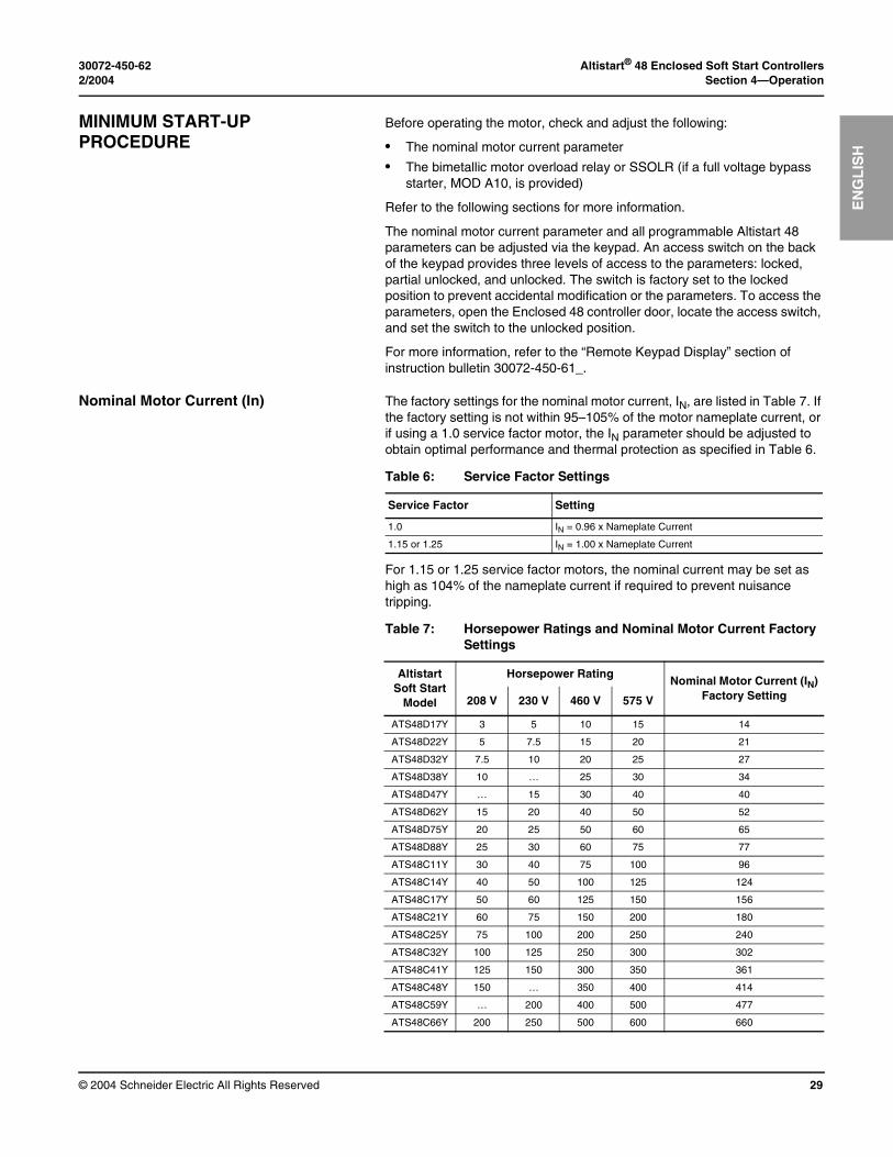
Nominal Motor Current (In) The factory settings for the nominal motor current, IN, are listed in Table 7. If the factory setting is not within 95–105% of the motor nameplate current, or if using a 1.0 service factor motor, the IN parameter should be adjusted to obtain optimal performance and thermal protection as specified in Table 6.
For 1.15 or 1.25 service factor motors, the nominal current may be set as high as 104% of the nameplate current if required to prevent nuisance tripping.
Table 6: Service Factor Settings
Service Factor Setting
1.0 IN = 0.96 x Nameplate Current
1.15 or 1.25 IN = 1.00 x Nameplate Current
Table 7: Horsepower Ratings and Nominal Motor Current Factory Settings
Altistart Soft Start
Model
Horsepower RatingNominal Motor Current (IN)
Factory Setting208 V 230 V 460 V 575 V
ATS48D17Y 3 5 10 15 14
ATS48D22Y 5 7.5 15 20 21
ATS48D32Y 7.5 10 20 25 27
ATS48D38Y 10 … 25 30 34
ATS48D47Y … 15 30 40 40
ATS48D62Y 15 20 40 50 52
ATS48D75Y 20 25 50 60 65
ATS48D88Y 25 30 60 75 77
ATS48C11Y 30 40 75 100 96
ATS48C14Y 40 50 100 125 124
ATS48C17Y 50 60 125 150 156
ATS48C21Y 60 75 150 200 180
ATS48C25Y 75 100 200 250 240
ATS48C32Y 100 125 250 300 302
ATS48C41Y 125 150 300 350 361
ATS48C48Y 150 … 350 400 414
ATS48C59Y … 200 400 500 477
ATS48C66Y 200 250 500 600 660
Altistart® 48 Enclosed Soft Start Controllers 30072-450-62Section 4—Operation 2/2004
© 2004 Schneider Electric All Rights Reserved30
EN
GL
ISH
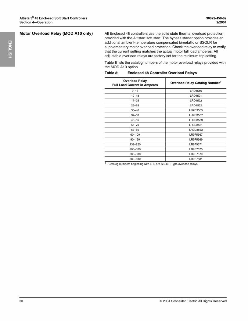
Motor Overload Relay (MOD A10 only) All Enclosed 48 controllers use the solid state thermal overload protection provided with the Altistart soft start. The bypass starter option provides an additional ambient-temperature compensated bimetallic or SSOLR for supplementary motor overload protection. Check the overload relay to verify that the current setting matches the actual motor full load amperes. All adjustable overload relays are factory set for the minimum trip setting.
Table 8 lists the catalog numbers of the motor overload relays provided with the MOD A10 option.
Table 8: Enclosed 48 Controller Overload Relays
Overload RelayFull Load Current in Amperes
Overload Relay Catalog Number1
1 Catalog numbers beginning with LR9 are SSOLR Type overload relays.
9–13 LRD1516
12–18 LRD1521
17–25 LRD1522
23–28 LRD1532
30–40 LR2D3555
37–50 LR2D3557
48–65 LR2D3559
55–70 LR2D3561
63–80 LR2D3563
60–100 LR9F5567
90–150 LR9F5569
132–220 LR9F5571
200–330 LR9F7575
300–500 LR9F7579
380–630 LR9F7581
30072-450-62 Altistart® 48 Enclosed Soft Start Controllers2/2004 Section 5—Maintenance
© 2004 Schneider Electric All Rights Reserved 31
EN
GL
ISH
SECTION 5— MAINTENANCE
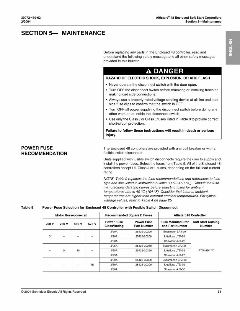
Before replacing any parts in the Enclosed 48 controller, read and understand the following safety message and all other safety messages provided in this bulletin.
POWER FUSE RECOMMENDATION
The Enclosed 48 controllers are provided with a circuit breaker or with a fusible switch disconnect.
Units supplied with fusible switch disconnects require the user to supply and install the power fuses. Select the fuses from Table 9. All of the Enclosed 48 controllers accept UL Class J or L fuses, depending on the full load current rating.
NOTE: Table 9 replaces the fuse recommendations and references to fuse type and size listed in instruction bulletin 30072-450-61_. Consult the fuse manufacturer derating curves before selecting fuses for ambient temperatures above 40 °C (104 °F). Consider that internal ambient temperatures are higher than external ambient temperatures. For typical wattage values, refer to Table 4 on page 25.
DANGERHAZARD OF ELECTRIC SHOCK, EXPLOSION, OR ARC FLASH
• Never operate the disconnect switch with the door open.
• Turn OFF the disconnect switch before removing or installing fuses or making load side connections.
• Always use a properly-rated voltage sensing device at all line and load side fuse clips to confirm that the switch is OFF.
• Turn OFF all power supplying the disconnect switch before doing any other work on or inside the disconnect switch.
• Use only the Class J or Class L fuses listed in Table 9 to provide correct short-circuit protection.
Failure to follow these instructions will result in death or serious injury.
Table 9: Power Fuse Selection for Enclosed 48 Controller with Fusible Switch Disconnect
Motor Horsepower at Recommended Square D Fuses Altistart 48 Controller
200 V 230 V 460 V 575 VPower Fuse Class/Rating
Power Fuse Part Number
Fuse Manufacturer and Part Number
Soft Start Catalog Number
J/20A 25423-30200 Bussmann LPJ-20
ATS48D17Y
3 – – – J/20A 25423-20200 Littelfuse JTD-20
J/20A Shawmut AJT-20
J/25A 25423-30250 Bussmannn LPJ-25
– 5 10 – J/25A 25423-20250 Littelfuse JTD-25
J/25A Shawmut AJT-25
J/30A 25423-30300 Bussmannn LPJ-30
– – – 15 J/30A 25423-20300 Littelfuse JTD-30
J/30A Shawmut AJT-30
Altistart® 48 Enclosed Soft Start Controllers 30072-450-62Section 5—Maintenance 2/2004
© 2004 Schneider Electric All Rights Reserved32
EN
GL
ISH
J/30A 25423-30300 Bussmannn LPJ-30
ATS48D22Y
5 – – – J/30A 25423-20300 Littelfuse JTD-30
J/30A Shawmut AJT-30
J/35A 25423-30350 Bussmannn LPJ-35
– – 15 – J/35A Littelfuse JTD-35
J/35A Shawmut AJT-35
J/40A 25423-30400 Bussmannn LPJ-40
– 7.5 – 20 J/40A 25423-20400 Littelfuse JTD-40
J/40A Shawmut AJT-40
J/45A 25423-30450 Bussmannn LPJ-45
ATS48D32Y
7.5 – 20 25 J/45A Littelfuse JTD-45
J/45A Shawmut AJT-45
J/50A 25423-30500 Bussmannn LPJ-50
– 10 – – J/50A 25423-20500 Littelfuse JTD-50
J/50A Shawmut AJT-50
J/50A 25423-30500 Bussmannn LPJ-50
ATS48D38Y
10 – – – J/50A 25423-20500 Littelfuse JTD-50
J/50A Shawmut AJT-50
J/60A 25423-30600 Bussmannn LPJ-60
– – 25 30 J/60A 25423-20600 Littelfuse JTD-60
J/60A Shawmut AJT-60
J/70A 25423-30700 Bussmannn LPJ-70
ATS48D47Y– 15 30 40 J/70A 25423-20700 Littelfuse JTD-70
J/70A Shawmut AJT-70
J/80A 25423-30800 Bussmannn LPJ-80
ATS48D62Y
15 – – – J/80A 25423-20800 Littelfuse JTD-80
J/80A Shawmut AJT-80
J/90A 25423-30900 Bussmannn LPJ-80
– 20 40 50 J/90A 25423-20900 Littelfuse JTD-80
J/90A Shawmut AJT-80
J/100A 25423-31000 Bussmannn LPJ-100
ATS48D75Y
20 – – – J/100A 25423-21000 Littelfuse JTD-100
J/100A Shawmut AJT-100
J/110A 25423-31100 Bussmannn LPJ-110
– – 50 60 J/110A 25423-21100 Littelfuse JTD-110
J/110A Shawmut AJT-110
– 25 – – J/125A 25423-31250 Bussmannn LPJ-125
J/125A 25423-21250 Littelfuse JTD-125
J/125A Shawmut AJT-125
J/125A 25423-31250 Bussmannn LPJ-125
ATS48D88Y
25 – 60 75 J/125A 25423-21250 Littelfuse JTD-125
J/125A Shawmut AJT-125
J/150A 25423-31500 Bussmannn LPJ-150
– 30 – – J/150A 25423-21500 Littelfuse JTD-150
J/150A Shawmut AJT-150
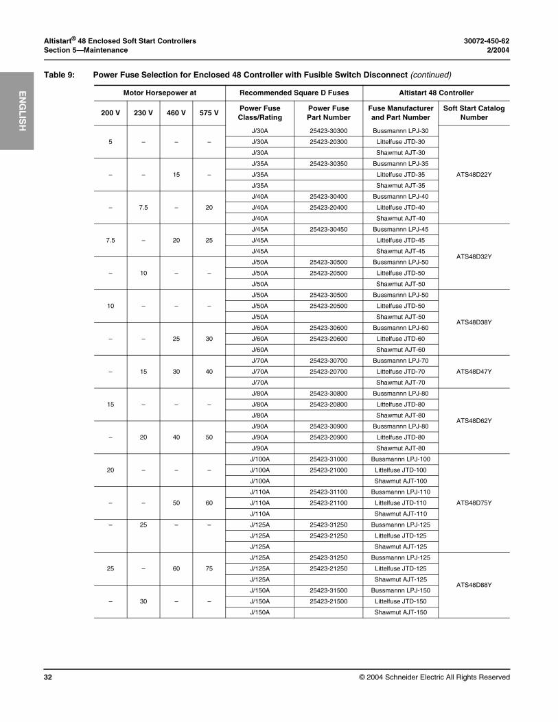
Table 9: Power Fuse Selection for Enclosed 48 Controller with Fusible Switch Disconnect (continued)
Motor Horsepower at Recommended Square D Fuses Altistart 48 Controller
200 V 230 V 460 V 575 VPower Fuse Class/Rating
Power Fuse Part Number
Fuse Manufacturer and Part Number
Soft Start Catalog Number
30072-450-62 Altistart® 48 Enclosed Soft Start Controllers2/2004 Section 5—Maintenance
© 2004 Schneider Electric All Rights Reserved 33
EN
GL
ISH
J/150A 25423-31500 Bussmannn LPJ-150
ATS48C11Y
30 – – – J/150A 25423-21500 Littelfuse JTD-150
J/150A Shawmut AJT-150
J/175A 25423-31750 Bussmannn LPJ-175
– 40 75 100 J/175A 25423-21750 Littelfuse JTD-175
J/175A Shawmut AJT-175
J/200A 25423-32000 Bussmannn LPJ-200
ATS48C14Y
40 – – – J/200A 25423-22000 Littelfuse JTD-200
J/200A Shawmut AJT-200
J/225A 25423-32250 Bussmannn LPJ-200
– 50 100 125 J/225A 25423-22250 Littelfuse JTD-200
J/225A Shawmut AJT-200
J/250A 25423-32500 Bussmannn LPJ-250
ATS48C17Y50 60 125 150 J/250A 25423-22500 Littelfuse JTD-250
J/250A Shawmut AJT-250
J/300A 25423-33000 Bussmannn LPJ-300
ATS48C21Y
60 – 150 – J/300A 25423-23000 Littelfuse JTD-300
J/300A Shawmut AJT-300
J/350A 25423-33500 Bussmannn LPJ-350
– 75 – 200 J/350A 25423-23500 Littelfuse JTD-350
J/350A Shawmut AJT-350
J/350A 25423-33500 Bussmannn LPJ-350
ATS48C25Y
75 – – – J/350A 25423-23500 Littelfuse JTD-350
J/350A Shawmut AJT-350
J/400A 25423-34000 Bussmannn LPJ-400
– 100 200 250 J/400A 25423-24000 Littelfuse JTD-400
J/400A Shawmut AJT-400
J/450A 25423-34500 Bussmannn LPJ-450
ATS48C32Y
100 – – – J/450A 25423-24500 Littelfuse JTD-450
J/450A Shawmut AJT-450
J/500A 25423-35000 Bussmannn LPJ-500
– 125 250 300 J/500A 25423-25000 Littelfuse JTD-500
J/500A Shawmut AJT-500
J/600A 25423-36000 Bussmannn LPJ-600
ATS48C41Y125 150 300 350 J/600A 25423-26000 Littelfuse JTD-600
J/600A Shawmut AJT-600
L/700A 25432-10700 Bussmannn KRP-C-700
ATS48C48Y150 – 350 400 L/700A Littelfuse KLP-C-700
L/700A Shawmut A4BQ-700
L/800A 25432-10800 Bussmannn KRP-C-800
ATS48C59Y– 200 400 500 L/800A Littelfuse KLP-C-800
L/800A Shawmut A4BQ-800
L/900A 25432-10900 Bussmann KRP-C-900
ATS48C66Y
200 – – – L/900A Littelfuse KLP-C-900
L/900A Shawmut A4BQ-900
L/1000A 25432-11000 Bussmann KRP-C-1000
– 250 500 600 L/1000A Littelfuse KLP-C-1000
L/1000A Shawmut A4BQ-1000
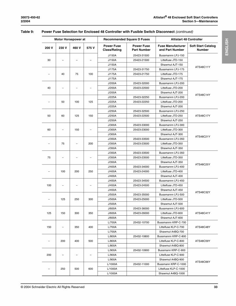
Table 9: Power Fuse Selection for Enclosed 48 Controller with Fusible Switch Disconnect (continued)
Motor Horsepower at Recommended Square D Fuses Altistart 48 Controller
200 V 230 V 460 V 575 VPower Fuse Class/Rating
Power Fuse Part Number
Fuse Manufacturer and Part Number
Soft Start Catalog Number
Altistart® 48 Enclosed Soft Start Controllers 30072-450-62Section 5—Maintenance 2/2004
© 2004 Schneider Electric All Rights Reserved34
EN
GL
ISH
TECHNICAL SUPPORT When troubleshooting the Class 8638 or Class 8639 Enclosed 48 controller, discuss with the operating personnel the symptoms of the reported problem. Ask them to describe the problem, when they first observed the problem, and where the problem was seen. Observe directly the controller and process. Record the controller, motor, and peripheral equipment nameplate data on the “Altistart 48 Class 8638/8639 Enclosed Controllers Troubleshooting Sheet” on page 35. (You may copy this form as needed.)
For more information, call, fax or write:
Schneider Electric Technical Support8001 Highway 64 EastKnightdale, NC 27545-9023
Telephone: 919-266-8600 or 1-888-SQUARED (1-888-778-2733)Fax Line: 919-217-6508e-Mail: [email protected]
30072-450-62 Altistart® 48 Enclosed Soft Start Controllers2/2004 Section 5—Maintenance
© 2004 Schneider Electric All Rights Reserved 35
EN
GL
ISH
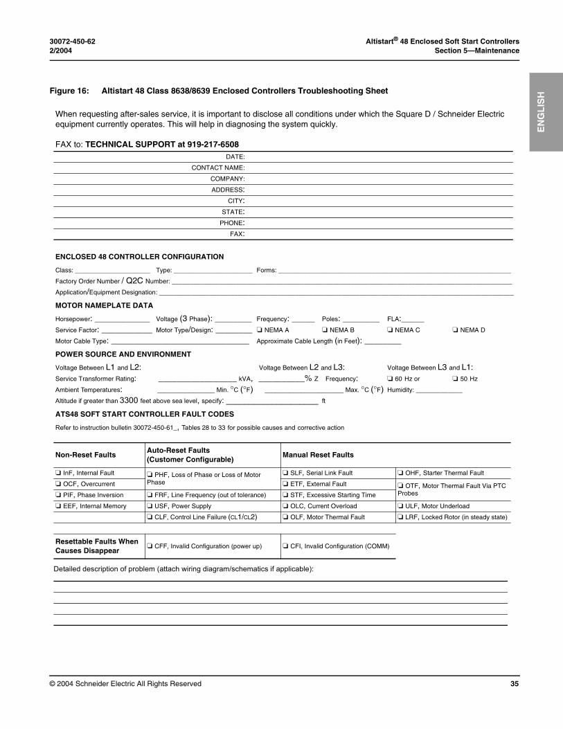
Figure 16: Altistart 48 Class 8638/8639 Enclosed Controllers Troubleshooting Sheet
Detailed description of problem (attach wiring diagram/schematics if applicable):
When requesting after-sales service, it is important to disclose all conditions under which the Square D / Schneider Electric equipment currently operates. This will help in diagnosing the system quickly.
FAX to: TECHNICAL SUPPORT at 919-217-6508DATE:
CONTACT NAME:
COMPANY:
ADDRESS:CITY:
STATE:PHONE:
FAX:
ENCLOSED 48 CONTROLLER CONFIGURATION
Class: _____________________ Type: ______________________ Forms: _________________________________________________________________
Factory Order Number / Q2C Number: _______________________________________________________________________________________________
Application/Equipment Designation: ___________________________________________________________________________________________________
MOTOR NAMEPLATE DATA
Horsepower: ____________ Voltage (3 Phase): ________ Frequency: _____ Poles: ________ FLA:_____Service Factor: ___________ Motor Type/Design: ________ ❏ NEMA A ❏ NEMA B ❏ NEMA C ❏ NEMA D
Motor Cable Type: ______________________________ Approximate Cable Length (in Feet): ________
POWER SOURCE AND ENVIRONMENT
Voltage Between L1 and L2: Voltage Between L2 and L3: Voltage Between L3 and L1:Service Transformer Rating: _________________ kVA, __________% Z Frequency: ❏ 60 Hz or ❏ 50 Hz
Ambient Temperatures: ________________ Min. °C (°F) ______________________ Max. °C (°F) Humidity: _____________
Altitude if greater than 3300 feet above sea level, specify: ____________________ ft
ATS48 SOFT START CONTROLLER FAULT CODES
Refer to instruction bulletin 30072-450-61_, Tables 28 to 33 for possible causes and corrective action
Non-Reset FaultsAuto-Reset Faults (Customer Configurable)
Manual Reset Faults
❏ InF, Internal Fault ❏ PHF, Loss of Phase or Loss of Motor Phase
❏ SLF, Serial Link Fault ❏ OHF, Starter Thermal Fault
❏ OCF, Overcurrent ❏ ETF, External Fault ❏ OTF, Motor Thermal Fault Via PTC Probes❏ PIF, Phase Inversion ❏ FRF, Line Frequency (out of tolerance) ❏ STF, Excessive Starting Time
❏ EEF, Internal Memory ❏ USF, Power Supply ❏ OLC, Current Overload ❏ ULF, Motor Underload
❏ CLF, Control Line Failure (CL1/CL2) ❏ OLF, Motor Thermal Fault ❏ LRF, Locked Rotor (in steady state)
Resettable Faults When Causes Disappear
❏ CFF, Invalid Configuration (power up) ❏ CFI, Invalid Configuration (COMM)

Altistart® 48 Enclosed Soft Start Controllers 30072-450-62Section 5—Maintenance 2/2004
© 2004 Schneider Electric All Rights Reserved36
EN
GL
ISH
30072-450-62 Altistart® 48 Enclosed Soft Start Controllers2/2004 Section 6—Replacement Parts
© 2004 Schneider Electric All Rights Reserved 37
EN
GL
ISH
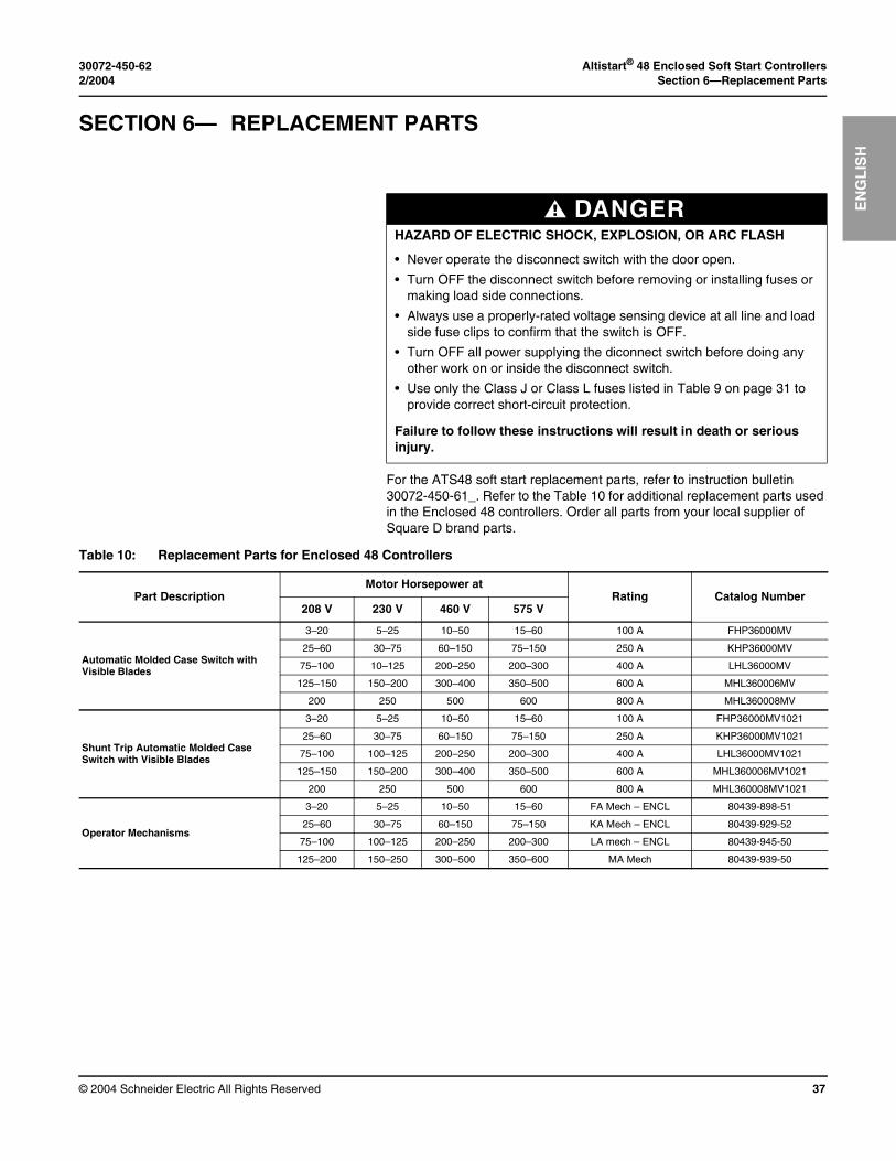
SECTION 6— REPLACEMENT PARTS
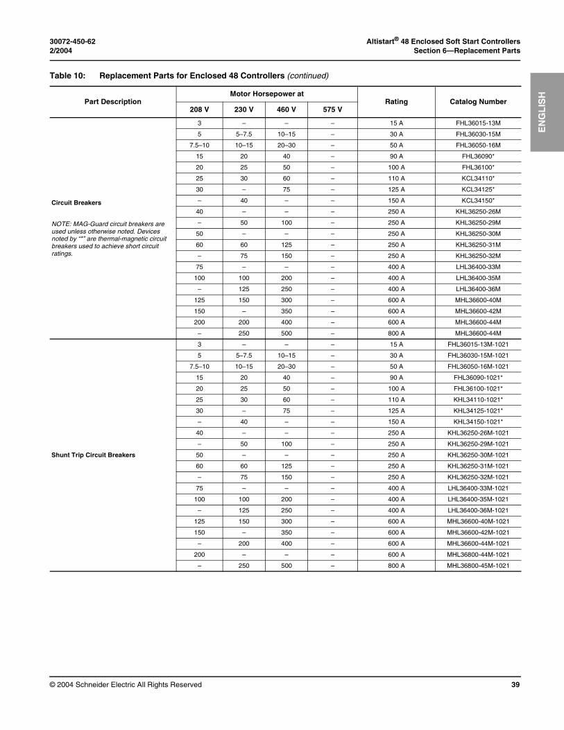
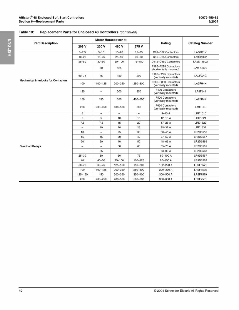
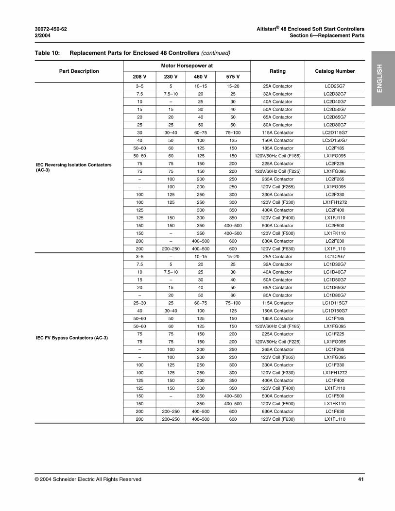
For the ATS48 soft start replacement parts, refer to instruction bulletin 30072-450-61_. Refer to the Table 10 for additional replacement parts used in the Enclosed 48 controllers. Order all parts from your local supplier of Square D brand parts.
DANGERHAZARD OF ELECTRIC SHOCK, EXPLOSION, OR ARC FLASH
• Never operate the disconnect switch with the door open.
• Turn OFF the disconnect switch before removing or installing fuses or making load side connections.
• Always use a properly-rated voltage sensing device at all line and load side fuse clips to confirm that the switch is OFF.
• Turn OFF all power supplying the diconnect switch before doing any other work on or inside the disconnect switch.
• Use only the Class J or Class L fuses listed in Table 9 on page 31 to provide correct short-circuit protection.
Failure to follow these instructions will result in death or serious injury.
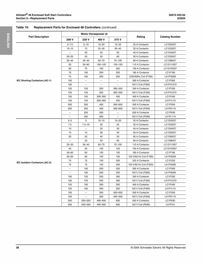
Table 10: Replacement Parts for Enclosed 48 Controllers
Part DescriptionMotor Horsepower at
Rating Catalog Number208 V 230 V 460 V 575 V
Automatic Molded Case Switch with Visible Blades
3–20 5–25 10–50 15–60 100 A FHP36000MV
25–60 30–75 60–150 75–150 250 A KHP36000MV
75–100 10–125 200–250 200–300 400 A LHL36000MV
125–150 150–200 300–400 350–500 600 A MHL360006MV
200 250 500 600 800 A MHL360008MV
Shunt Trip Automatic Molded Case Switch with Visible Blades
3–20 5–25 10–50 15–60 100 A FHP36000MV1021
25–60 30–75 60–150 75–150 250 A KHP36000MV1021
75–100 100–125 200–250 200–300 400 A LHL36000MV1021
125–150 150–200 300–400 350–500 600 A MHL360006MV1021
200 250 500 600 800 A MHL360008MV1021
Operator Mechanisms
3–20 5–25 10–50 15–60 FA Mech – ENCL 80439-898-51
25–60 30–75 60–150 75–150 KA Mech – ENCL 80439-929-52
75–100 100–125 200–250 200–300 LA mech – ENCL 80439-945-50
125–200 150–250 300–500 350–600 MA Mech 80439-939-50
Altistart® 48 Enclosed Soft Start Controllers 30072-450-62Section 6—Replacement Parts 2/2004
© 2004 Schneider Electric All Rights Reserved38
EN
GL
ISH
IEC Shorting Contactors (AC-1)
3–7.5 5–10 10–20 15–25 25 A Contactor LC1D25G7
10–15 15 25–30 30–40 32 A Contactor LC1D32G7
– 20 40 50 40 A Contactor LC1D40G7
20–25 25 50 60 50 A Contactor LC1D50G7
30–40 30–40 60–75 75–100 80 A Contactor LC1D80G7
50 50–60 100–125 125–150 115 A Contactor LC1D115G7
60 75 150 200 150 A Contactor LC1D150G7
75 100 200 250 185 A Contactor LC1F185
75 100 200 250 120V/60Hz Coil (F185) LX1FG095
100 – – – 265 A Contactor LC1F265
100 – – – 120 V Coil (F265) LX1FH1272
125 125 250 300–350 330 A Contactor LC1F330
125 125 250 300–350 120 V Coil (F330) LX1FH1272
150 150 300–350 400 400 A Contactor LC1F400
150 150 300–350 400 120 V Coil (F400) LX1FJ110
200 200 400 500–600 500 A Contactor LC1F500
200 200 400 500–600 120 V Coil (F500) LX1FK110
– 250 500 – 630 A Contactor LC1F630
– 250 500 – 120 V Coil (F630) LX1FL110
IEC Isolation Contactors (AC-3)
3–5 5 10–15 15–20 25 A Contactor LC1D25G7
7.5 7.5–10 20 25 32 A Contactor LC1D32G7
10 – 25 30 40 A Contactor LC1D40G7
15 15 30 40 50 A Contactor LC1D50G7
20 20 40 50 65 A Contactor LC1D65G7
– 25 50 60 80 A Contactor LC1D80G7
25–30 30–40 60–75 75–100 115 A Contactor LC1D115G7
40 50 100 125 150 A Contactor LC1D150G7
50–60 60 125 150 185 A Contactor LC1F185
50–60 60 125 150 120 V/60 Hz Coil (F185) LX1FG095
75 75 150 200 225 A Contactor LC1F225
75 75 150 200 120 V/60 Hz Coil (F225) LX1FG095
– 100 200 250 265 A Contactor LC1F265
– 100 200 250 120 V Coil (F265) LX1FG095
100 125 250 300 330 A Contactor LC1F330
100 125 250 300 120 V Coil (F330) LX1FH1272
125 150 300 250 400 A Contactor LC1F400
125 150 300 250 120 V Coil (F400) LX1FJ110
150 – 350 400–500 500 A Contactor LC1F500
150 – 350 400–500 120 V Coil (F500) LX1FK110
200 200–250 400–500 600 630 A Contactor LC1F630
200 200–250 400–500 600 120 V Coil (F630) LX1Fl10
Table 10: Replacement Parts for Enclosed 48 Controllers (continued)
Part DescriptionMotor Horsepower at
Rating Catalog Number208 V 230 V 460 V 575 V
30072-450-62 Altistart® 48 Enclosed Soft Start Controllers2/2004 Section 6—Replacement Parts
© 2004 Schneider Electric All Rights Reserved 39
EN
GL
ISH
Circuit Breakers
NOTE: MAG-Guard circuit breakers are used unless otherwise noted. Devices noted by “*” are thermal-magnetic circuit breakers used to achieve short circuit ratings.
3 – – – 15 A FHL36015-13M
5 5–7.5 10–15 – 30 A FHL36030-15M
7.5–10 10–15 20–30 – 50 A FHL36050-16M
15 20 40 – 90 A FHL36090*
20 25 50 – 100 A FHL36100*
25 30 60 – 110 A KCL34110*
30 – 75 – 125 A KCL34125*
– 40 – – 150 A KCL34150*
40 – – – 250 A KHL36250-26M
– 50 100 – 250 A KHL36250-29M
50 – – – 250 A KHL36250-30M
60 60 125 – 250 A KHL36250-31M
– 75 150 – 250 A KHL36250-32M
75 – – – 400 A LHL36400-33M
100 100 200 – 400 A LHL36400-35M
– 125 250 – 400 A LHL36400-36M
125 150 300 – 600 A MHL36600-40M
150 – 350 – 600 A MHL36600-42M
200 200 400 – 600 A MHL36600-44M
– 250 500 – 800 A MHL36600-44M
Shunt Trip Circuit Breakers
3 – – – 15 A FHL36015-13M-1021
5 5–7.5 10–15 – 30 A FHL36030-15M-1021
7.5–10 10–15 20–30 – 50 A FHL36050-16M-1021
15 20 40 – 90 A FHL36090-1021*
20 25 50 – 100 A FHL36100-1021*
25 30 60 – 110 A KHL34110-1021*
30 – 75 – 125 A KHL34125-1021*
– 40 – – 150 A KHL34150-1021*
40 – – – 250 A KHL36250-26M-1021
– 50 100 – 250 A KHL36250-29M-1021
50 – – – 250 A KHL36250-30M-1021
60 60 125 – 250 A KHL36250-31M-1021
– 75 150 – 250 A KHL36250-32M-1021
75 – – – 400 A LHL36400-33M-1021
100 100 200 – 400 A LHL36400-35M-1021
– 125 250 – 400 A LHL36400-36M-1021
125 150 300 – 600 A MHL36600-40M-1021
150 – 350 – 600 A MHL36600-42M-1021
– 200 400 – 600 A MHL36600-44M-1021
200 – – – 600 A MHL36800-44M-1021
– 250 500 – 800 A MHL36800-45M-1021
Table 10: Replacement Parts for Enclosed 48 Controllers (continued)
Part DescriptionMotor Horsepower at
Rating Catalog Number208 V 230 V 460 V 575 V
Altistart® 48 Enclosed Soft Start Controllers 30072-450-62Section 6—Replacement Parts 2/2004
© 2004 Schneider Electric All Rights Reserved40
EN
GL
ISH
Mechanical Interlocks for Contactors
3–7.5 5–10 10–20 15–25 D09–D32 Contactors LAD9R1V
10–20 15–25 25–50 30–60 D40–D65 Contactors LA9D4002
25–50 30–50 60–100 75–150 D115–D150 Contactors LA9D11502
– 60 125 – F185–F225 Contactors(horizontally mounted) LA9FG970
60–75 75 150 200F185–F225 Contactors
(vertically mounted) LA9FG4G
100 100–125 200–250 250–300 F265–F330 Contactors(vertically mounted)
LA9FH4H
125 – 300 350 F400 Contactors(vertically mounted) LA9FJ4J
150 150 350 400–500F500 Contactors
(vertically mounted) LA9FK4K
200 200–250 400–500 600 F630 Contactors(vertically mounted)
LA9FL4L
Overload Relays
3 – – – 9–13 A LRD1516
5 5 10 15 12–18 A LRD1521
7.5 7.5 15 20 17–25 A LRD1522
– 10 20 25 25–32 A LRD1532
10 – 25 30 30–40 A LR2D3555
15 15 30 40 37–50 A LR2D3557
20 20 40 50 48–65 A LR2D3559
– – 50 60 55–70 A LR2D3561
– 25 – – 63–80 A LR2D3563
25–30 30 60 75 60–100 A LR9D5567
40 40–50 75–100 100–125 90–150 A LR9D5569
50–75 60–75 125–150 150–200 132–220 A LR9F5571
100 100–125 200–250 250–300 200–330 A LR9F7575
125–150 150 300–350 350–400 300–500 A LR9F7579
200 200–250 400–500 500–600 380–630 A LR9F7581
Table 10: Replacement Parts for Enclosed 48 Controllers (continued)
Part DescriptionMotor Horsepower at
Rating Catalog Number208 V 230 V 460 V 575 V
30072-450-62 Altistart® 48 Enclosed Soft Start Controllers2/2004 Section 6—Replacement Parts
© 2004 Schneider Electric All Rights Reserved 41
EN
GL
ISH
IEC Reversing Isolation Contactors (AC-3)
3–5 5 10–15 15–20 25A Contactor LCD25G7
7.5 7.5–10 20 25 32A Contactor LC2D32G7
10 – 25 30 40A Contactor LC2D40G7
15 15 30 40 50A Contactor LC2D50G7
20 20 40 50 65A Contactor LC2D65G7
25 25 50 60 80A Contactor LC2D80G7
30 30–40 60–75 75–100 115A Contactor LC2D115G7
40 50 100 125 150A Contactor LC2D150G7
50–60 60 125 150 185A Contactor LC2F185
50–60 60 125 150 120V/60Hz Coil (F185) LX1FG095
75 75 150 200 225A Contactor LC2F225
75 75 150 200 120V/60Hz Coil (F225) LX1FG095
– 100 200 250 265A Contactor LC2F265
– 100 200 250 120V Coil (F265) LX1FG095
100 125 250 300 330A Contactor LC2F330
100 125 250 300 120V Coil (F330) LX1FH1272
125 300 350 400A Contactor LC2F400
125 150 300 350 120V Coil (F400) LX1FJ110
150 150 350 400–500 500A Contactor LC2F500
150 – 350 400–500 120V Coil (F500) LX1FK110
200 – 400–500 600 630A Contactor LC2F630
200 200–250 400–500 600 120V Coil (F630) LX1FL110
IEC FV Bypass Contactors (AC-3)
3–5 – 10–15 15–20 25A Contactor LC1D2G7
7.5 5 20 25 32A Contactor LC1D32G7
10 7.5–10 25 30 40A Contactor LC1D40G7
15 – 30 40 50A Contactor LC1D50G7
20 15 40 50 65A Contactor LC1D65G7
– 20 50 60 80A Contactor LC1D80G7
25–30 25 60–75 75–100 115A Contactor LC1D115G7
40 30–40 100 125 150A Contactor LC1D150G7
50–60 50 125 150 185A Contactor LC1F185
50–60 60 125 150 120V/60Hz Coil (F185) LX1FG095
75 75 150 200 225A Contactor LC1F225
75 75 150 200 120V/60Hz Coil (F225) LX1FG095
– 100 200 250 265A Contactor LC1F265
– 100 200 250 120V Coil (F265) LX1FG095
100 125 250 300 330A Contactor LC1F330
100 125 250 300 120V Coil (F330) LX1FH1272
125 150 300 350 400A Contactor LC1F400
125 150 300 350 120V Coil (F400) LX1FJ110
150 – 350 400–500 500A Contactor LC1F500
150 – 350 400–500 120V Coil (F500) LX1FK110
200 200–250 400–500 600 630A Contactor LC1F630
200 200–250 400–500 600 120V Coil (F630) LX1FL110
Table 10: Replacement Parts for Enclosed 48 Controllers (continued)
Part DescriptionMotor Horsepower at
Rating Catalog Number208 V 230 V 460 V 575 V
Altistart® 48 Enclosed Soft Start Controllers 30072-450-62Section 6—Replacement Parts 2/2004
© 2004 Schneider Electric All Rights Reserved42
EN
GL
ISH
30072-450-62 Altistart® 48 Enclosed Soft Start Controllers2/2004 Index
© 2004 Schneider Electric All Rights Reserved 43
En
glis
hE
NG
LIS
H
Numerics3-phase supply voltage 5Aambient air temperature 5ambient pollution 5ATS48 3–4Bbimetallic overload relay 29–30booster start-up pulse 5Bypass/Normal 27Ccircuit breaker 3circuit diagrams 27Class 8638 3–4Class 8639 3–4conformity to standards 5customer terminal block 4, 26Ddegree of protection 5duty cycle 5EEnclosed 48 controllers 25–26
bypass starter 27control wiring 26enclosure types 12estimated watts loss 25exceptions to bulletin 30072-450-61 3factory settings 28hoisting 10improper mounting 10installation 11load wiring 26maintenance 31mounting dimensions 12operation 27overload relays 30power fuses 31related documentation 3replacement parts 37standard features 4start-up procedures 29technical specifications 3–4technical support 34troubleshooting 35weights 12wiring 25
enclosure typesfloor mounted
size D 15–18size E 19–20, 22
wall mountedsize A 12size B 13size C 14
estiamted watts loss 25exceptions to bulletin 30072-450-61 3
Ffactory setings 28full voltage bypass 5fusible disconnect 3HHazard Categories and Special Symbols 2hoisting 10horsepower ratings 29Iinstallation 3
precautions 11isolation contactor 5Lline input 26load terminals 4load wiring 26MMOD 4, 6, 27MOD A10 27, 29Nnominal motor current 28–29OOCPD 5, 26Ppower circuit weights 25power fuse recommendations 31–33Rreplacement parts 37–41SSCR 5seismic qualifications 5service factor settings 29short circuit current ratings 7short circuit ratings 4shorting contactor 5shunt-trip disconnect 5soft start controllers 3SSOLR 4, 27, 29–30Ttechnical specifications 4–5
catalog number 6environment 5MOD 7
technical support 34terminology 4thermal overload 5thermal switch 5torque ramp 5troubleshooting 35Wwiring 25
Altistart® 48 Enclosed Soft Start Controllers 30072-450-62Index 2/2004
© 2004 Schneider Electric All Rights Reserved44
En
glish
EN
GL
ISH


Electrical equipment should be installed, operated, serviced, and maintained only by qualified personnel. No responsibility is assumed by Schneider Electric for any consequences arising out of the use of this material.
30072-450-62 © 2004 Schneider Electric All Rights Reserved
8001 Highway 64 EastKnightdale, NC 275451-888-SquareD (1-888-778-2733)www.SquareD.com
2/2004
Schneider Electric
Instruction BulletinAltistart® 48 Enclosed Soft Start Controllers


