
Public Authority for Civil Aviation
DETERMINATION OF AERODROME OPERATING MINIMA (AOM)
GUIDANCE MATERIAL GM – CAR-173
Copyright © 2018 by the Air Navigation Safety Department - DGCAR All rights reserved. No part of this publication may be stored in a retrieval system, transmitted, or reproduced in
any way, including but not limited to photo-copy, magnetic or other record, without the prior agreement and written permission of the DGCAR.
Manual No: 1.3.9. Issue Date: 01 October 2018 Revision Number: 01
AERODROME OPERATING MINIMA Rev: 01
Date of Issue: 01 October 2018 | Public Authority for Civil Aviation Page ii
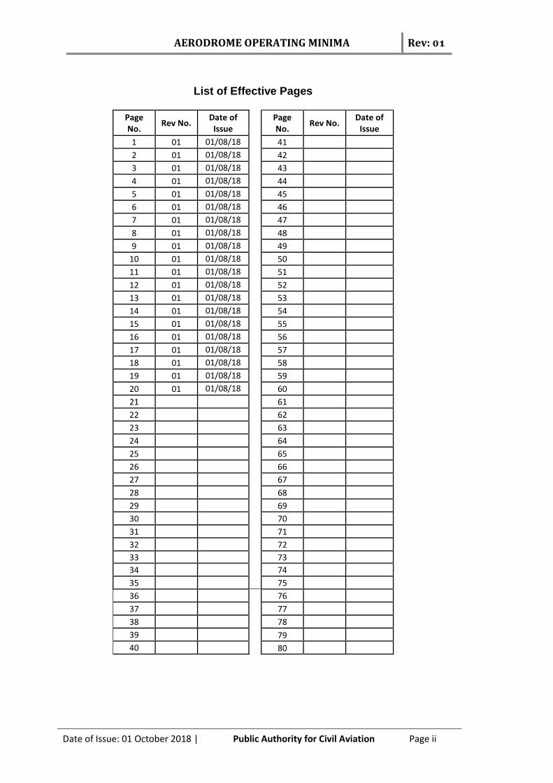
List of Effective Pages
Page No.
Rev No. Date of
Issue Page
No. Rev No.
Date of Issue
1 01 01/08/18 41
2 01 01/08/18 42
3 01 01/08/18 43
4 01 01/08/18 44
5 01 01/08/18 45
6 01 01/08/18 46
7 01 01/08/18 47
8 01 01/08/18 48
9 01 01/08/18 49
10 01 01/08/18 50
11 01 01/08/18 51
12 01 01/08/18 52
13 01 01/08/18 53
14 01 01/08/18 54
15 01 01/08/18 55
16 01 01/08/18 56
17 01 01/08/18 57
18 01 01/08/18 58
19 01 01/08/18 59
20 01 01/08/18 60
21 61
22 62
23 63
24 64
25 65
26 66
27 67
28 68
29 69
30 70
31 71
32 72
33 73
34 74
35 75
36 76
37 77
38 78
39 79 40 80
AERODROME OPERATING MINIMA Rev: 01
Date of Issue: 01 October 2018 | Public Authority for Civil Aviation Page iii
INTENTIONALL LEFT BLANK

AERODROME OPERATING MINIMA Rev: 01
Date of Issue: 01 October 2018 | Public Authority for Civil Aviation Page iv
TABLE OF CONTENTS List of Effective Pages ................................................................................................................ ii
FOREWORD…………………………………………………………………………………………………………………………..1
CHAPTER 1 - GENERAL CONCEPTS ............................................................................................ 2
1.1 INTRODUCTION ............................................................................................. 2
1.2 DEFINITIONS ................................................................................................. 2
1.3 ABBREVIATIONS/ACRONYMS ....................................................................... 7
VSS Visual segment surface ................................................................................ 8
CHAPTER 2. DETERMINATION OF AERODROME OPERATING MINIMA .................................... 9
2.1 Factors affecting operational minima .......................................................... 9
2.2 The minimum values of DH or MDH ............................................................ 9
2.3 Approach Lighting Systems. ........................................................................ 10
2.4 Determination of RVR/ Visibility minima .................................................... 11
2.4 Publication .................................................................................................. 12
APPENDIX 1. System Minima v. Facilities ......................................................................... 13
APPENDIX 2. RVR/CMV v. DH/MDH ................................................................................. 14
APPENDIX 3. Minimum and maximum applicable RVR for all instrument approaches down to CAT I minima (lower and upper cut-off limits) ............................. 15
APPENDIX 4. Minimum Visibility and MDH for Circling v. Aeroplane Category .............. 16
AERODROME OPERATING MINIMA Rev: 01
Date of Issue: 01 October 2018 | Public Authority for Civil Aviation Page 1
FOREWORD This Guidance Material provides guidance to CAR-173:
(a) ANSD in the oversight of their service providers in the calculation and promulgation of operating minima;
(b) Organizations responsible for instrument flight procedure (IFP) development to aid them in determination of AOM in a manner consistent with the provisions of CAR-OPS 1 and CAR-173;
(c) Aerodrome operators and ANSP to understand how aerodrome operating minima are determined as well as to highlight the need for the provision of ground facilities and services when planning to implement all-weather operations; and
(d) Flight crew-members and other personnel who need to understand the AOM methods of calculation.
The AOM are published on instrument approach charts. They constitute the lowest operating minima that can be used without an operational approval by the aircraft operator's surveillance authority. The aerodrome operating minima are published as MDH/DH and RVR/Visibility for the following approach procedures:
Category II precision approaches with DH greater than or equal to 100 ft;
Category I precision approaches with DH greater than or equal to 200 ft;
Approaches with vertical guidance (APV);
Non precision approaches; and
Visual manoeuvres.
It is the responsibility of IPDSP to establish Aerodrome Operating Minima to be published in the Oman AIP for each instrument approach procedure and circling procedure developed at aerodromes as per CAR-173. This Guidance Material is effective from 01 October 2018.
AERODROME OPERATING MINIMA Rev: 01
Date of Issue: 01 October 2018 | Public Authority for Civil Aviation Page 2
CHAPTER 1 - GENERAL CONCEPTS 1.1 INTRODUCTION
(1) Aerodrome Operating Minima are established in order to ensure the desired level of
safety in Aeroplane Operations at an Aerodrome by limiting these operations in
specified weather conditions. The values of aerodrome operating minima for a
particular operation must ensure that at all times the combination of information
available from external sources and the aeroplane instruments and equipment is
sufficient to enable the aeroplane to be operated along the desired flight path.
(2) This CAP lays down the methods used in the calculation of aerodrome operating minima
Aerodrome operating Minima for Omani aerodromes.
(3) The authority determines and publishes aerodrome operating minima as MDH/DH and
RVR/Visibility for the following approach procedures:
Category II precision approaches with DH greater than or equal to 100 ft;
Category I precision approaches with DH greater than or equal to 200 ft;
Approaches with vertical guidance (APV);
Non precision approaches; and
Visual manoeuvres.
(4) The minima are published on the instrument approach charts. They constitute the
lowest operating minima that can be used without an operational approval by the
aircraft operator's surveillance authority.
(5) It is the responsibility of IPDSP to establish Aerodrome Operating Minima to be published in the Oman AIP for each instrument approach procedure and circling procedure developed at aerodromes as per CAR-173.
1.2 DEFINITIONS When the following terms are used in this Guidance Material (GM) they have the following meanings:
(1) Aerodrome operating minima. The limits of usability of an aerodrome for:
(a) take-off, expressed in terms of runway visual range and/or visibility and, if necessary, cloud conditions;
(b) landing in precision approach and landing operations, expressed in terms of visibility and/or runway visual range and decision altitude/height (DA/H) as appropriate to the category of the operation;
(c) landing in approach and landing operations with vertical guidance, expressed in terms of visibility and/or runway visual range and decision altitude/height (DA/H); and
(d) landing in non-precision approach and landing operations, expressed in terms of visibility and/or runway visual range, minimum descent altitude/height (MDA/H) and, if necessary, cloud conditions.

AERODROME OPERATING MINIMA Rev: 01
Date of Issue: 01 October 2018 | Public Authority for Civil Aviation Page 3
(2) Approach and landing operations using instrument approach procedures. Instrument
approach and landing operations are classified as follows:
(a) Non-precision approach and landing operations. An instrument approach and
landing which utilizes lateral guidance but does not utilize vertical guidance.
(b) Approach and landing operations with vertical guidance. An instrument
approach and landing which utilizes lateral and vertical guidance but does not
meet the requirements established for precision approach and landing
operations.
(c) Precision approach and landing operations. An instrument approach and landing
using precision lateral and vertical guidance with minima as determined by the
category of operation.
Note: Lateral and vertical guidance refers to the guidance provided either by: (a) a ground-based navigation aid; or
(b) computer generated navigation data.
(3) Categories of precision approach and landing operations:
(a) Category I (CAT I) operation. A precision instrument approach and landing with:
i. a decision height not lower than 60 m (200 ft); and
ii. with either a visibility not less than 800 m or a runway visual range not less
than 550 m.
(b) Category II (CAT II) operation. A precision instrument approach and landing with:
i. a decision height lower than 60 m (200 ft), but not lower than 30 m (100 ft);
and
ii. a runway visual range not less than 300 m.
(c) Category IIIA (CAT IIIA) operation. A precision instrument approach and landing
with:
i. a decision height lower than 30 m (100 ft) or no decision height; and
ii. a runway visual range not less than 175 m.
(d) Category IIIB (CAT IIIB) operation. A precision instrument approach and landing
with:
i. a decision height lower than 15 m (50 ft), or no decision height; and
ii. a runway visual range less than 175 m but not less than 50 m.
(e) Category IIIC (CAT IIIC) operation. A precision instrument approach and landing
with no decision height and no runway visual range limitations.
Note: Where decision height (DH) and runway visual range (RVR) fall into different categories of operation, the instrument approach and landing operation would be conducted in accordance with the requirements of the most demanding category (e.g. an operation with a DH in the range of CAT IIIA but with an RVR in the range of CAT IIIB would be considered a CAT IIIB operation or an operation with a DH in the range of CAT II but with an RVR in the range of CAT I would be considered a CAT II operation).
AERODROME OPERATING MINIMA Rev: 01
Date of Issue: 01 October 2018 | Public Authority for Civil Aviation Page 4
(4) Categories of aeroplanes. The following five categories of aeroplanes have been
established based on 1.3 times the stall speed in the landing configuration at maximum
certificated landing mass:
(a) Category A — less than 169 km/h (91 kt) IAS
(b) Category B — 169 km/h (91 kt) or more but less than 224 km/h (121 kt) IAS
(c) Category C — 224 km/h (121 kt) or more but less than 261 km/h (141 kt) IAS
(d) Category D — 261 km/h (141 kt) or more but less than 307 km/h (166 kt) IAS
(e) Category E — 307 km/h (166 kt) or more but less than 391 km/h (211 kt) IAS.
(5) Circling approach. An extension of an instrument approach procedure which provides
for visual circling of the aerodrome prior to landing.
(6) Continuous descent final approach (CDFA). A technique, consistent with stabilized
approach procedures, for flying the final approach segment of a non-precision
instrument approach procedure as a continuous descent, without level-off, from an
altitude/height at or above the final approach fix altitude/height to a point
approximately 15 m (50 ft) above the landing runway threshold or the point where the
flare manoeuvre should begin for the type of aircraft flown.
(7) Converted meteorological visibility (CMV). A value (equivalent to an RVR) which is
derived from the reported meteorological visibility.
(8) Decision altitude (DA) or decision height (DH). A specified altitude or height in the
precision approach or approach with vertical guidance at which a missed approach must
be initiated if the required visual reference to continue the approach has not been
established.
Note 1: Decision altitude (DA) is referenced to mean sea level and decision height (DH) is referenced to the threshold elevation.
Note 2: The required visual reference means that section of the visual aids or of the approach area, which should have been in view for sufficient time for the pilot to have made an assessment of the aircraft position and rate of change of position, in relation to the desired flight path. In Category III operations with a decision height the required visual reference is that specified for the particular procedure and operation.
Note 3: For convenience where both expressions are used they may be written in the form “decision altitude/height” and abbreviated “DA/H”.
(8) Final approach. That part of an instrument approach procedure which commences at
the specified final approach fix or point, or where such a fix or point is not specified,
(a) at the end of the last procedure turn, base turn or inbound turn of a racetrack
procedure, if specified; or
(b) at the point of interception of the last track specified in the approach
procedure; and
(c) ends at a point in the vicinity of an aerodrome from which:
AERODROME OPERATING MINIMA Rev: 01
Date of Issue: 01 October 2018 | Public Authority for Civil Aviation Page 5
i. a landing can be made; or
ii. a missed approach procedure is initiated.
(9) Final approach segment. That segment of an instrument approach procedure in which
alignment and descent for landing are accomplished.
(10) Instrument approach procedure. A series of predetermined manoeuvres by reference
to flight instruments with specified protection from obstacles from the initial approach
fix, or where applicable, from the beginning of a defined arrival route to a point from
which a landing can be completed and thereafter, if a landing is not completed, to a
position at which holding or en-route obstacle clearance criteria apply. Instrument
approach procedures are classified as follows:
(a) Non-precision approach (NPA) procedure. An instrument approach procedure
which utilizes lateral guidance but does not utilize vertical guidance.
(b) Approach procedure with vertical guidance (APV). An instrument approach
procedure which utilizes lateral and vertical guidance but does not meet the
requirements established for precision approach and landing operations.
(c) Precision approach (PA) procedure. An instrument approach procedure using
precision lateral and vertical guidance with minima as determined by the
category of operation.
Note: Lateral and vertical guidance refers to the guidance provided either by: (a) a ground-based navigation aid; or
(b) computer-generated navigation data.
(11) Minimum descent altitude (MDA) or minimum descent height (MDH). A specified
altitude or height in a non-precision approach or circling approach below which
descent must not be made without the required visual reference.
Note 1: Minimum descent altitude (MDA) is referenced to mean sea level and minimum descent height (MDH) is referenced to the aerodrome elevation or to the threshold elevation if that is more than 2 m (7 ft) below the aerodrome elevation. A minimum descent height for a circling approach is referenced to the aerodrome elevation.
Note 2: The required visual reference means that section of the visual aids or of the approach area which should have been in view for sufficient time for the pilot to have made an assessment of the aircraft position and rate of change of position, in relation to the desired flight path. In the case of a circling approach the required visual reference is the runway environment.
Note 3: For convenience when both expressions are used they may be written in the form “minimum descent altitude/height” and abbreviated “MDA/H”.
(12) Obstacle clearance altitude (OCA) or obstacle clearance height (OCH). The lowest
altitude or the lowest height above the elevation of the relevant runway threshold or
the aerodrome elevation as applicable, used in establishing compliance with
appropriate obstacle clearance criteria.
AERODROME OPERATING MINIMA Rev: 01
Date of Issue: 01 October 2018 | Public Authority for Civil Aviation Page 6
Note 1: Obstacle clearance altitude is referenced to mean sea level and obstacle clearance height is referenced to the threshold elevation or in the case of non-precision approaches to the aerodrome elevation or the threshold elevation if that is more than 2 m (7 ft) below the aerodrome elevation. An obstacle clearance height for a circling approach is referenced to the aerodrome elevation.
Note 2: For convenience when both expressions are used they may be written in the form “obstacle clearance altitude/ height” and abbreviated “OCA/H”.
(13) Runway visual range (RVR). The range over which the pilot of an aircraft on the centre
line of a runway can see the runway surface markings or the lights delineating the
runway or identifying its centre line.
(14) Vertical navigation (VNAV). A method of navigation which permits aircraft operation
on a vertical flight profile using altimetry sources, external flight path references, or a
combination of these.
(15) Visibility. Visibility for aeronautical purposes is the greater of:
(a) the greatest distance at which a black object of suitable dimensions, situated
near the ground, can be seen and recognized when observed against a bright
background;
(b) the greatest distance at which lights in the vicinity of 1 000 candelas can be
seen and identified against an unlit background.
Note 1: The two distances have different values in air of a given extinction coefficient, and the latter b) varies with the background illumination. The former a) is represented by the meteorological optical range (MOR).
Note. 2: The definition applies to the observations of visibility in local routine and special reports, to the observations of prevailing and minimum visibility reported in METAR and SPECI and to the observations of ground visibility.
AERODROME OPERATING MINIMA Rev: 01
Date of Issue: 01 October 2018 | Public Authority for Civil Aviation Page 7
1.3 ABBREVIATIONS/ACRONYMS
AIP Aeronautical information publication AIS Aeronautical information service ANSD Air Navigation Safety Department AOM Aerodrome operating minima APV Approach procedure with vertical guidance BALS Basic approach lighting system CAA Civil Aviation Authority CAR Civil Aviation Regulations CAT I Category I CAT II Category II CAT III Category III CDFA Continuous descent final approach CFIT Controlled flight into terrain CMV Converted meteorological visibility DA Decision altitude DA/H Decision altitude/height DGCAR Director General for Civil Aviation Regulation DH Decision height DME Distance measuring equipment FAF Final approach fix FALS Full approach lighting system HATh Height above threshold HIALS High intensity approach lighting system IALS Intermediate approach lighting system IAS Indicated airspeed IFR Instrument flight rules ILS Instrument landing system IMC Instrument meteorological conditions IPDSP Instrument Procedure Design Service Provider LOC Localizer LNAV Lateral navigation MDA Minimum descent altitude MDA/H Minimum descent altitude/height MDH Minimum descent height MIALS Medium intensity approach and lighting system MOC Minimum obstacle clearance NALS No approach lighting system NDB Non-directional beacon OCA Obstacle clearance altitude OCA/H Obstacle clearance altitude/height OCH Obstacle clearance height PACA Public Authority for Civil Aviation PANS Procedures for Air Navigation Services PANS-OPS Procedures for Air Navigation Services Aircraft Operations PAR Precision approach radar

AERODROME OPERATING MINIMA Rev: 01
Date of Issue: 01 October 2018 | Public Authority for Civil Aviation Page 8
RCLL Runway centre line lights RNAV Area navigation RNP Required navigation performance RTZL Runway touchdown zone lights RVR Runway visual range SRA Surveillance radar approach TDZ Touchdown zone THR Threshold VDF Very high frequency direction-finding station VFR Visual flight rules VIS Visibility VMC Visual meteorological conditions VNAV Vertical navigation VOR Very high frequency omnidirectional radio range
VSS Visual segment surface
AERODROME OPERATING MINIMA Rev: 01
Date of Issue: 01 October 2018 | Public Authority for Civil Aviation Page 9
CHAPTER 2. DETERMINATION OF AERODROME OPERATING MINIMA 2.1 Factors affecting operational minima
In general, minima are developed by adding the effect of a number of operational factors to OCA/H to produce, in the case of precision approaches, decision altitude (DA) or decision height (DH), in the case of non-precision approaches, minimum descent altitude (MDA) or minimum descent height (MDH). The general operational factors to be considered are specified in Annex 6.
As per CAR–OPS 1.430 Aerodrome Operating Minima, It’s the responsibility of the airline operator to establish, for each aerodrome planned to be used, aerodrome operating minima that are not lower than any that may be established for such aerodromes by the State in which the aerodrome is located, except when specifically approved by that State. It is the responsibility of IPDSP to establish Aerodrome Operating Minima to be published in the Oman AIP for each instrument approach procedure and circling procedure developed at aerodromes as per the provision of this CAP. 2.2 The minimum values of DH or MDH 2.2.1 Precision approach — Category II
The decision height for Category II approach shall be the higher of:
The OCH for the category of aeroplane; or
100 ft.
2.2.2 Precision approach — Category I
The decision height for Category I approach shall be the higher of: The OCH for the category of aeroplane; or
200 ft.
2.2.3 APV approach
The decision height for APV approach shall be the higher of:
The OCH for the category of aeroplane; or
250 ft.
2.2.4 A non-precision approach (NPA)
The MDH for an NPA approach shall be the higher of:
the OCH for the category of aeroplane; or
the system minimum in table annexed hereto as Appendix 1.

AERODROME OPERATING MINIMA Rev: 01
Date of Issue: 01 October 2018 | Public Authority for Civil Aviation Page 10
2.2.5 Circling
(a) The MDH for circling shall be the higher of:
the OCH for the aeroplane category; or
the minimum circling height derived from Table in appendix 4; or
the DH/MDH of the preceding instrument approach procedure. (b) Minimum descent altitude (MDA). The MDA for circling shall be calculated by adding
the published aerodrome elevation to the MDH, as determined by a) above. (c) Published DA, DH, MDA, MDH must be expressed in feet rounded to the next higher 10-
foot increment.
2.3 Approach Lighting Systems.
(a) Visual aids are designed to increase the conspicuousness of the runway, provide visual references in the final stages of the approach and landing and expedite surface movement. The importance of visual aids increases as visibility becomes limited. Approach lighting, runway centre line lighting, runway edge lighting and runway markings provide a reference for the pilot to assess lateral position and cross-track velocity. The approach lighting and threshold lighting and markings provide a roll reference. Touchdown zone (TDZ) lighting and markings indicate the plane of the runway surface and show the touchdown area providing vertical and longitudinal references.
(b) The length and shape of the approach lights play an essential role in the determination of the landing minima. Shorter approach lighting systems require greater RVR. Therefore, the length of the approach lights is directly correlated with the RVR. Approach lighting systems are described in Annex 14, Volume I. Examples of approach lighting system configurations are described in Table 2-1 below.
Table 2-1. Approach lighting systems
Class of facility Length, configuration and
intensity of approach lights
FALS (full approach lighting system) Precision approach CAT I lighting system (HIALS ≥ 720 m) Distance coded centre line, barrette centre line
IALS (intermediate approach lighting system) Simple approach lighting system (HIALS 420 m to 719 m) Single source, barrette
BALS (basic approach lighting system) Any other approach lighting system (HIALS, MIALS or ALS 210 m to 419 m)
NALS (no approach lighting system) Any other approach lighting system (HIALS, MIALS or ALS < 210 m) or no approach lights
(c) Detailed description of the Approach lighting systems for each airport is contained in
AIP Oman section AD 2.14 Approach and runway lighting.
AERODROME OPERATING MINIMA Rev: 01
Date of Issue: 01 October 2018 | Public Authority for Civil Aviation Page 11
2.4 Determination of RVR/ Visibility minima
2.4.1 RVR for cat II
The lowest minima for Category II operations are:
RVR for Cat II operations v. DH
Decision height (ft) RVR (m)(1)
Aeroplane Category A, B & C
Aeroplane Category D
100–120 300m 300(2)/350
121–140 400 400
141 and above 450 450
Note 1: The values in the table represent the absolute minimum RVR under the most
favourable operating conditions. Note 2: If autoland operations supported by the airport facilities, RVR for cat D can be reduced
to 300m. 2.4.2 RVR for CAT I, APV and NPA
(a) RVR greater or equal to 750 m
The determination of the RVR values is based on the joint use of the two annexed tables in Appendixes 2 and 3.
As a first step, for each aeroplane category, the table in Appendix 2 shall be use for obtaining an initial value of RVR. There are three possible scenarios :
If the value obtained is situated between MNM and MAX as determined by table in appendix 3, this value is selected and to be published;
If the value obtained is less than the MNM value as determined by table in appendix 3, in such a case, the MNM value of the table is selected and to be published;
If the value obtained is greater than the MAX value as determined by table in appendix 3, in such a case, the MAX value of the table is selected and to be published;
(b) RVR Lower than 750 m
An RVR of less than 750 m as indicated in appendix 2 may be used for Category I approach operations to runways with FALS (see below), Runway Touchdown Zone Lights (RTZL) and Runway Centerline Lights (RCLL) provided that the DH is not more than 200 ft.
(c) Use of Appendix 3 for minimum and maximum values of RVR
In order to qualify for the lowest allowable values of RVR/CMV detailed in appendix 3 (applicable to each approach grouping) the instrument approach shall meet at least the following facility requirements and associated conditions:

AERODROME OPERATING MINIMA Rev: 01
Date of Issue: 01 October 2018 | Public Authority for Civil Aviation Page 12
(1) Instrument approaches with designated vertical profile up to and including 4.5°
for Category A and B aeroplanes, or 3.77° for Category C and D aeroplanes, unless
other approach angles are approved by the Authority, where the facilities are:
i. ILS/MLS/GLS/PAR; or
ii. APV; and
iii. where the final approach track is offset by not more than 15° for Category
A and B aeroplanes or by not more than 5° for Category C and D
aeroplanes.
(2) Instrument approaches flown using the CDFA technique with a nominal vertical
profile, up to and including 4.5° for Category A and B aeroplanes, or 3.77° for
Category C and D aeroplanes, unless other approach angles are approved by the
Authority where the facilities are NDB, NDB/DME, VOR, VOR/DME, LLZ, LLZ/DME,
VDF, SRA or RNAV/LNAV, with a final-approach segment of at least 3NM, which
also fulfil the following criteria:
i. The final approach track is offset by not more than 15° for Category A and B aeroplanes or by not more than 5° for Category C and D aeroplanes; and
ii. The FAF or another appropriate fix where descent is initiated is available, or distance to THR is available by RNAV or DME; and
iii. If the MAPt is determined by timing, the distance from FAF to THR is ≤ 8 NM.
(3) Instrument approaches where the facilities are NDB, NDB/DME, VOR, VOR/DME, LLZ, LLZ/DME, VDF, SRA or RNAV/LNAV, not fulfilling the criteria in paragraph (c)(2) above, or with an MDH ≥ 1 200 ft.
2.4.3 Visibility for circling
The minimum visibility for circling shall be the higher of:
the minimum visibility derived from Table in appendix 4; or
the RVR for the preceding instrument approach procedure.
2.4 Publication
The IPDSP is requested to provide with the IFP Package a draft chart of the instrument approach procedure (IAC). Doing so requires to :
Provide minimums for each approach category accommodated at the airport ;
Annotate the chart appropriately when one or more approach categories are not
authorized. Publish minima for each approach category except those not authorized
(e.g. publish only category A and B straight-in minimums when categories C and D are
not authorized or publish only straight-in minimums when circling is not authorized at
the aerodrome).

AERODROME OPERATING MINIMA Rev: 01
Date of Issue: 01 October 2018 | Public Authority for Civil Aviation Page 13
APPENDIX 1. System Minima v. Facilities
Facility Lowest DH/MDH
Localiser with or without DME 250 ft
SRA (terminating at 1/2 NM) 250 ft
SRA (terminating at 1 NM) 300 ft
SRA (terminating at 2 NM or more) 350 ft
RNAV/LNAV 300 ft
VOR 300 ft
VOR/DME 250 ft
NDB 350 ft
NDB/DME 300 ft
VDF 350 ft

AERODROME OPERATING MINIMA Rev: 01
Date of Issue: 01 October 2018 | Public Authority for Civil Aviation Page 14
APPENDIX 2. RVR/CMV v. DH/MDH
DH or MDH
Class of Lighting Facility
FALS IALS BALS NALS
See paragraphs 2.4.2 (b) about RVR < 750 m
feet metres
200 — 210 550 750 1 000 1 200
211 — 220 550 800 1 000 1 200
221 — 230 550 800 1 000 1 200
231 — 240 550 800 1 000 1 200
241 — 250 550 800 1 000 1 300
251 — 260 600 800 1 100 1 300
261 — 280 600 900 1 100 1 300
281 — 300 650 900 1 200 1 400
301 — 320 700 1 000 1 200 1 400
321 — 340 800 1 100 1 300 1 500
341 — 360 900 1 200 1 400 1 600
361 — 380 1 000 1 300 1 500 1 700
381 — 400 1 100 1 400 1 600 1 800
401 — 420 1 200 1 500 1 700 1 900
421 — 440 1 300 1 600 1 800 2 000
441 — 460 1 400 1 700 1 900 2 100
461 — 480 1 500 1 800 2 000 2 200
481 — 500 1 500 1 800 2 100 2 300
501 — 520 1 600 1 900 2 100 2 400
521 — 540 1 700 2 000 2 200 2 400
541 — 560 1 800 2 100 2 300 2 500
561 — 580 1 900 2 200 2 400 2 600
581 — 600 2 000 2 300 2 500 2 700
601 — 620 2 100 2 400 2 600 2 800
621 — 640 2 200 2 500 2 700 2 900
641 — 660 2 300 2 600 2 800 3 000
661 — 680 2 400 2 700 2 900 3 100
681 — 700 2 500 2 800 3 000 3 200
701 — 720 2 600 2 900 3 100 3 300
721 — 740 2 700 3 000 3 200 3 400
741 — 760 2 700 3 000 3 300 3 500
761 — 800 2 900 3 200 3 400 3 600
801 — 850 3 100 3 400 3 600 3 800
851 — 900 3 300 3 600 3 800 4 000
901 — 950 3 600 3 900 4 100 4 300
951 — 1000 3 800 4 100 4 300 4 500
1001 — 1100 4 100 4 400 4 600 4 900
1101 — 1200 4 600 4 900 5 000 5 000
1 201 and above 5 000 5 000 5 000 5 000
AERODROME OPERATING MINIMA Rev: 01
Date of Issue: 01 October 2018 | Public Authority for Civil Aviation Page 15
APPENDIX 3. Minimum and maximum applicable RVR for all instrument approaches down to CAT I minima (lower and upper cut-off limits)
Facility/conditions RVR/CMV (m)
Aeroplane category
A B C D
ILS, MLS, GLS, PAR and APV
Min According to Table in appendix 2
Max 1 500 1 500 2 400 2 400
NDB, NDB/DME, VOR, VOR/DME, LLZ, LLZ/DME, VDF, SRA, RNAV/LNAV with a procedure which fulfils the criteria in paragraph 2.4.2 (c)(ii):
Min
750 750 750 750
Max 1 500 1 500 2 400 2 400
For NDB, NDB/DME, VOR, VOR/DME, LLZ, LLZ/DME, VDF, SRA, RNAV/LNAV: — not fulfilling the criteria in paragraph 2.4.2 (c).(ii) , or — with a DH or MDH ≥ 1 200 ft
Min
1 000 1 000 1 200 1 200
Max According to appendix 2 if flown using the CDFA technique, otherwise an add-on of 200/400 m applies to the values in appendix 2 but not to result in a value exceeding 5 000 m.
AERODROME OPERATING MINIMA Rev: 01
Date of Issue: 01 October 2018 | Public Authority for Civil Aviation Page 16
APPENDIX 4. Minimum Visibility and MDH for Circling v. Aeroplane Category
Aeroplane Category
A B C D
MDH (ft) 400 500 600 700
Minimum meteorological
visibility (m) 1 500 1 600 2 400 3 600


