
Thermoelectric Valve Drives Technical Data Sheet
Actuator : 230 V Standard
The Actuator 230 V Standard is a thermoelectric valve drive for opening and closing valves on heating circuit distributors of concealed floor heating and cooling systems. The main field of application is the energy-efficient individual room temperature control in the range of building management systems and home automation. The Actuator 230 V is controlled by a 230 V room thermostat with two point output or pulse-width modulation.
The Actuator of the fifth generation has been developed especially for customer-specific usage in the OEM business. The modular design offers several possibilities for differentiations for
tailor-made versions.
1.1 Features
Modern OEM design
Stroke variants 4.0 mm (other stroke variants on demand)
Available in normally closed (NC)
Power consumption 1 watt
Complete compatibility to Valve-Adapter-System
Simple snap-on installation
360° installation position
Patented 100% protection against leaky valves
First-Open function (NC type only, optional)
Adaptation check on valve
Alignment aid on the valve
Compact size, small dimensions
All around function indicator
Noiseless and maintenance-free
High functional safety and long expected service life
Surge protection guarantee
Certified by TÜV
1.2 Versions
In the basic version, the Actuator 5 230 V Standard is delivered with fixed connecting cable, function indicator blue / gray, without valveadapter and laser marking.
Versions 230 V: stroke actuating
force de-energised
state closing and
opening time
"First-Open"
function scope of supply
A204 4.0 mm 100 N NC ~ 3.5 min yes Actuator 5 230 V in single package
1 meter connecting cable, greyPVC H03VV 2 x 0.75 mm²
installation manual in 12 languages
Optionally, the following extensions and differentiations of the basic version are available:
Cable length 2 m, 3 m, 5 m, PVC H03VV in grey – 2 x 0.75 mm2
Valve Adapter Adapters are available for all standard valves and manifolds
Packaging Packaging can be printed or produced individually according to your requirements
Imprint on casing Laser imprint of your company logo and of an individual type designation
Colour of casing and cable Homogenous colouring, colour function indicator and function cap, matching your product design or corporate design.
Non-halogen line 1 m, 2 m, 3 m, 5 m, Hal F H03Z1Z1 in white – 2 x 0.75 mm² Compliance with fire protection and environmental regulations
NRTL approval Approval according to UL specification
Further versions available on request.
Accessories
Protection Cap SK 1004
Pettinaroli A/SMandal Allé 215500 MiddelfartDENMARK
+45 6341 [email protected]
Thermoelectric Valve Drives Technical Datasheet
2 Functions
The actuator mechanism of the Actuator uses a PTC resistor-heated wax element and a compression spring. The wax element is heated by applying the operating voltage and moves the integrated ram. The force generated by the movement is transferred on the valve lifter and thus opens and closes the valve.
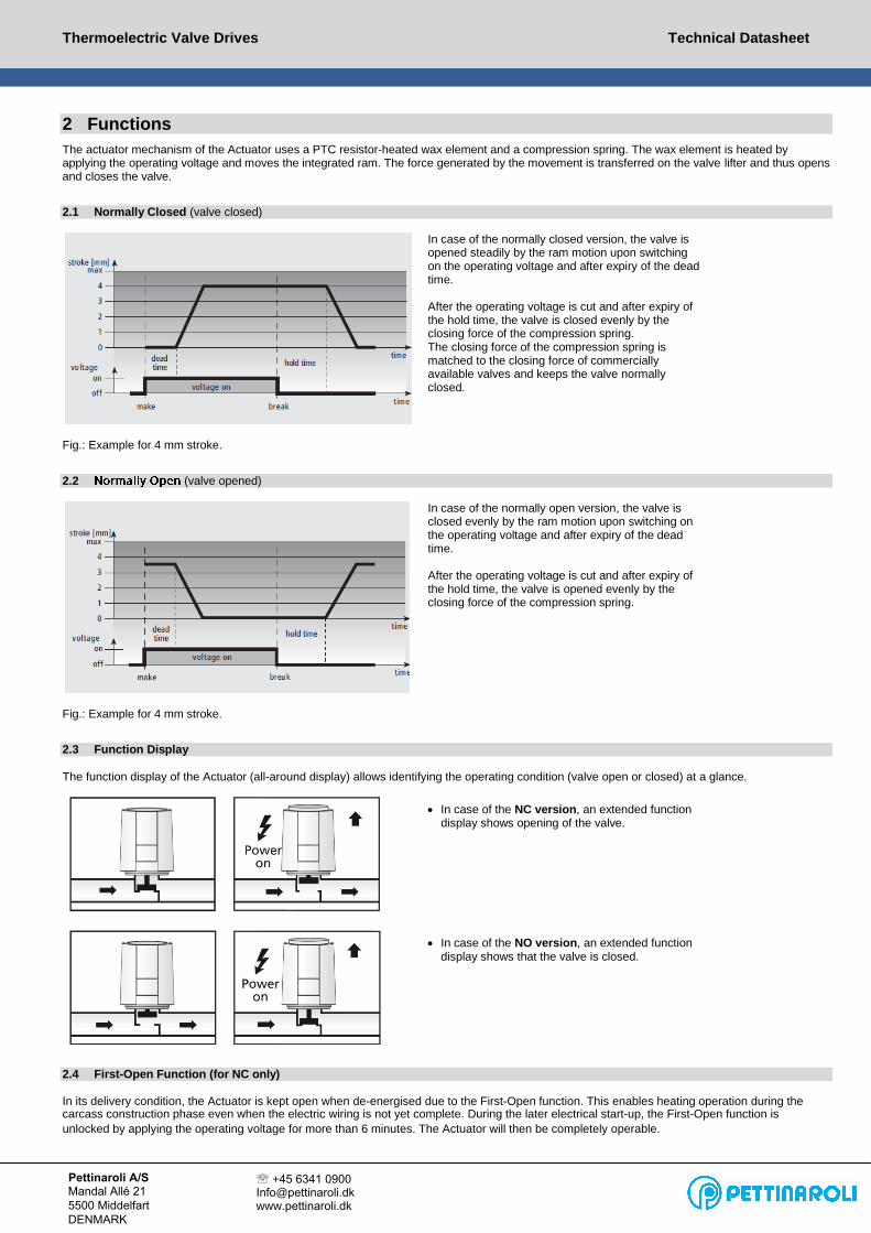
2.1 Normally Closed (valve closed)
In case of the normally closed version, the valve is opened steadily by the ram motion upon switching on the operating voltage and after expiry of the dead time.
After the operating voltage is cut and after expiry of the hold time, the valve is closed evenly by the closing force of the compression spring. The closing force of the compression spring is matched to the closing force of commercially available valves and keeps the valve normally closed.
Fig.: Example for 4 mm stroke.
2.2 (valve opened)
In case of the normally open version, the valve is closed evenly by the ram motion upon switching on the operating voltage and after expiry of the dead time.
After the operating voltage is cut and after expiry of the hold time, the valve is opened evenly by the closing force of the compression spring.
Fig.: Example for 4 mm stroke.
2.3 Function Display
The function display of the Actuator (all-around display) allows identifying the operating condition (valve open or closed) at a glance.
In case of the NC version, an extended functiondisplay shows opening of the valve.
In case of the NO version, an extended functiondisplay shows that the valve is closed.
2.4 First-Open Function (for NC only)
In its delivery condition, the Actuator is kept open when de-energised due to the First-Open function. This enables heating operation during the carcass construction phase even when the electric wiring is not yet complete. During the later electrical start-up, the First-Open function is
unlocked by applying the operating voltage for more than 6 minutes. The Actuator will then be completely operable.
Pettinaroli A/SMandal Allé 215500 MiddelfartDENMARK
+45 6341 [email protected]

Thermoelectric Valve Drives Technical Datasheet
3 Technical Informations
Operating voltage 230 V AC, +10%...–10%, 50/60 Hz
1) measured with precision reference instrument LMG952) in dependence of the adapter even higher3) in all installation positions
Max. inrush current < 550 mA during 100 ms max.
Operating power 1 W 1)
Stroke (actuator travel) 4.0
Actuating force 100 N +5 %
Fluid temperature 0 to +100°C 2)
Storage temperature -25°C to +60°C
Ambient temperature 0 to +60°C
Degree of protection II
Type of protection IP 54 3)
CE conformity according to EN 60730
Housing material/housing colour Polyamide / light grey (RAL 7035)
Connecting cable/colour 2 x 0.75 mm2 PVC / light grey (RAL 7035)
Cable length 1 m
Weight with connecting cable (1 meter) 100 g
Surge protection according to EN 60730-1 2.5 kV
3.1 Dimensions
Dimensions Installation height
3.2 Certificates
The Actuator is certified by TÜV Süd.
48,4 mm
52,2
mm
44,3 mm
50,3
mm
7 m
m
Pettinaroli A/SMandal Allé 215500 MiddelfartDENMARK
+45 6341 [email protected]
Pettinaroli A/SMandal Allé 215500 MiddelfartDENMARK
+45 6341 [email protected]
Thermoelectric Valve Drives Technical Datasheet
4 Installation Notes
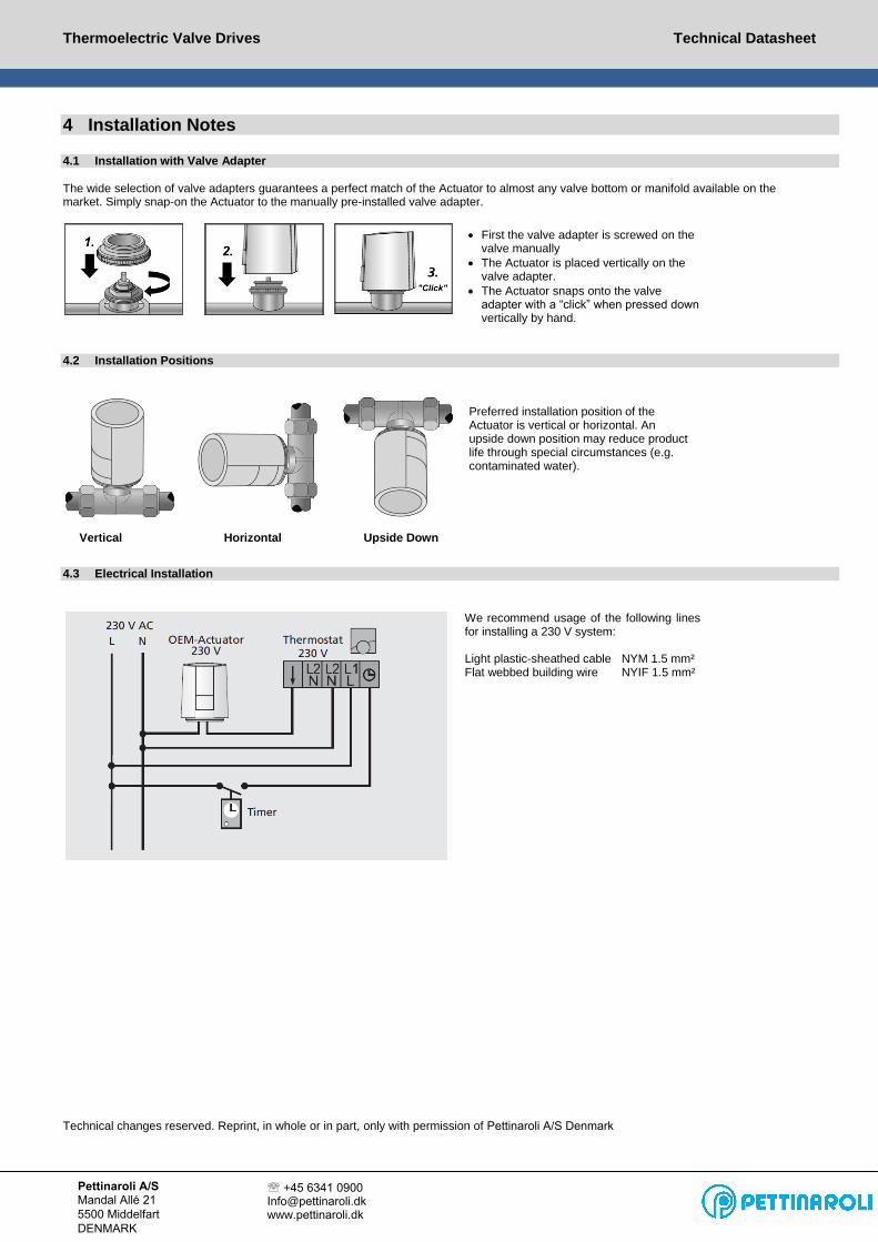
4.1 Installation with Valve Adapter
The wide selection of valve adapters guarantees a perfect match of the Actuator to almost any valve bottom or manifold available on the market. Simply snap-on the Actuator to the manually pre-installed valve adapter.
First the valve adapter is screwed on thevalve manually
The Actuator is placed vertically on thevalve adapter.
The Actuator snaps onto the valveadapter with a “click” when pressed downvertically by hand.
4.2 Installation Positions
Vertical Horizontal Upside Down
Preferred installation position of the Actuator is vertical or horizontal. Anupside down position may reduce product life through special circumstances (e.g. contaminated water).
4.3 Electrical Installation
We recommend usage of the following lines for installing a 230 V system:
Light plastic-sheathed cable NYM 1.5 mm² Flat webbed building wire NYIF 1.5 mm²
Technical changes reserved. Reprint, in whole or in part, only with permission of Pettinaroli A/S Denmark
Pettinaroli A/SMandal Allé 215500 MiddelfartDENMARK
+45 6341 [email protected]


