�������� ����� ��
A Heuristic Approach for Petrochemical Plant Layout Considering SteamPipeline Length
Yan Wu, Yufei Wang, Xiao Feng
PII: S1004-9541(16)30376-7DOI: doi: 10.1016/j.cjche.2016.04.043Reference: CJCHE 545
To appear in:
Please cite this article as: Yan Wu, Yufei Wang, Xiao Feng, A Heuristic Approachfor Petrochemical Plant Layout Considering Steam Pipeline Length, (2016), doi:10.1016/j.cjche.2016.04.043
This is a PDF file of an unedited manuscript that has been accepted for publication.As a service to our customers we are providing this early version of the manuscript.The manuscript will undergo copyediting, typesetting, and review of the resulting proofbefore it is published in its final form. Please note that during the production processerrors may be discovered which could affect the content, and all legal disclaimers thatapply to the journal pertain.

ACC
EPTE
D M
ANU
SCR
IPT
ACCEPTED MANUSCRIPT
A Heuristic Approach for Petrochemical Plant Layout Considering
Steam Pipeline Length
WU Yan (吴艳), WANG Yufei (王彧斐)* and FENG Xiao (冯霄)
State Key Laboratory of Heavy Oil Processing, China University of Petroleum, Beijing 102249, China
稿件编号:2015-0471
中文文题:考虑蒸汽管线长度的石化工厂布局启发式方法
Abstract Plant layout design affects both investment and performance of a factory. To maximize the economic
benefits of a petrochemical factory, a large number of factors must be considered simultaneously, such as material
flow, heat flow and safety. However, conventional principles for plant layout design and optimization do not
involve the heat flow, resulting in higher construction investment. To solve this problem, a new heuristic approach
is proposed in this paper based on the current layout design principles. Both material flow (pipelines for process
streams) and heat flow (pipelines for steam) are considered. Three optimization methods with different objective
functions are used to optimize the layout. The application of proposed approach is illustrated with a case study.
The optimal scheme and pipeline networks can be obtained, and the pipeline length is reduced significantly.
Keywords petrochemical plant layout; heuristic; steam system; pipeline length; optimization
1 INTRODUCTION
Plant layout is an important aspect in the design of petrochemical factory and a good layout
will provide an effective way to increase economic benefits and reduce heat and mass losses. To
various objective functions for layout design, the design is normally carried out with expert
experience. A lot of work on petrochemical plant layout design is based on practical experience [1,
2], concluding safety [3], device characteristic [4, 6, 7], heat integration [5], space requirements
*Supported by the National Basic Research Program of China (2012CB720500) and the National Natural Science Foundation of China
(21306228). ** To whom correspondence should be addressed. [email protected]
ACC
EPTE
D M
ANU
SCR
IPT
ACCEPTED MANUSCRIPT
[8], maintenance and operational considerations [9], and so on. No systematic methodology has
been proposed. The plant layout of petrochemical factory is a branch of facility layout problem
(FLP), which has been extensively studied in the area of industrial engineering [10]. FLP is to
determine the most effective department arrangement in a facility, to minimize material handling
costs [11]. A facility may be a production factory, an administrative building or service facility
[12]. To solve a FLP, various methods have been proposed including heuristic approaches and
mathematical programming methods. Hillier has developed a pairwise exchange heuristic [13].
Skorin-Kapov has applied the tabu search heuristic [14]. Chandratre and Nandurkar have used
genetic algorithm [15]. FLP is widely applied in the areas such as hospitals [16], ship cabin [17],
and autonomous material handling system such as mobile robot or automated guided vehicle [18].
However, these methods are hardly applied to petrochemical plant layout. This is mainly due
to the characteristics of petrochemical enterprises, such as high-risk, large-scale, strong continuity
and massive energy consumption, especially the complexity of material and heat flows. Nowadays,
there is no effective methodology to simultaneously satisfy different objective functions and
multiple constraint conditions. Only single objective function is involved, such as safety [19] and
pipe network length of heat exchanger (heat integration) [20].
To reduce the pipeline investment, material flow pipeline network has been taken into
consideration in the design of petrochemical plant layout. In this paper, both material and heat
flows are considered in the design of plant layout for the first time. The major pipeline network of
heat flow is steam system in a petrochemical plant. By considering the length of steam pipeline,
conventional layout design method for petrochemical plants is more economical and reasonable.
ACC
EPTE
D M
ANU
SCR
IPT
ACCEPTED MANUSCRIPT
2 METHODOLOGY
In order to obtain the shortest length of pipe network, heuristic method is used to optimize
plant layout in this work. Practical factors such as material flow, steam consumption,
technological process, transportation, environment and safety are considered.
This section consists of three methods for layout designs with different objective functions:
(1) the shortest length of material flow pipelines, (2) the shortest length of steam pipelines, and (3)
the shortest total length of material and steam pipelines.
2.1 Method 1
This method is used to design plant layout for shorter material flow pipeline. A number of
principles are developed on the basis of Chemical Engineering Design [21], Preliminary Chemical
Engineering Plant Design [22], and Petrochemical plant layout design specification (GB
50984-2014)[23]. The content is as follows.
a. For safe operation and less energy consumption, the plants using hydrogen at high
temperature and high pressure, such as gas oil hydrocracking and residue hydrotreating, are
close to the hydrogen production installment.
b. The units include aromatic hydrocarbons, isomerization, continuous reforming and naphtha
hydrotreating are placed jointly because of their upstream and downstream relationship.
Sulfur recovery and delayed coker are close to each other. Fluid catalytic cracking plant is the
most close to its upstream installment residue hydrotreating.
c. Crude oil fractionation unit is near crude oil storage, which is its upstream facility. Processes
for final products, such as diesel, kerosene and gasoline, are preferred to stay together and
close to the storage devices.

ACC
EPTE
D M
ANU
SCR
IPT
ACCEPTED MANUSCRIPT
d. The power station locates at the edge of the factory, near the railway and delayed coker. This
layout not only reduces the environment pollution caused by coal dust, but also facilitates the
supply of fuel coal and petroleum coke.
e. The utility such as air separation unit, air compressor station, de-salt water station and water
treatment are close to the main users, shortening pipeline and avoiding heat loss. Air
separation and air compressor plant is far away from the power station for a good air
environment, which is beneficial to improving equipment operation.
f. Sewage treatment is in low-lying areas of the refinery, preventing sewage from flow
backward and helping environmental protection. To reduce the pipeline investment, sulfur
recovery unit, which produces a great deal of waste-water, should be close to sewage farm.
g. Comprehensive administrative zone locates in the higher ground for safety and is close to
downtown and highway to avoid potential safety hazards for commuting of employees.
These principles are listed according to the decreasing order of importance. They may give
some contradictions. In the design process the designer should meet the principles in the front of
the list and meet the requirements of production process and environmental protection
simultaneously as far as possible.
2.2 Method 2
Method 2 is to minimize the length of steam pipeline network.
In general, the steam system of petrochemical plants consists of three levels of steams (ignore
other grades used in some special devices or cases), i.e., high pressure steam (3.5 MPa), medium
pressure steam (1.0 MPa) and low pressure steam (0.4 MPa). The steam pipeline investment cost
increases sharply from low pressure steam to high pressure steam. For pipeline arrangement, high
ACC
EPTE
D M
ANU
SCR
IPT
ACCEPTED MANUSCRIPT
pressure steam is preferred and low pressure steam is considered last. Power station is an
important process to produce steam, so its location is determined first in the layout design. The
rules are as follows.
a. It is better for the power plant to locate at the edge of the factory based on Method 1(d). To
increase its effective connection area, it is better not to put the power station and storage
together. Otherwise it will increase the length of steam pipeline due to large storage area.
b. High pressure steam users are close to the power station, especially those with large steam
consumption. This arrangement can reduce the length and diameter of high pressure steam
pipeline, reducing the investment, the loss of steam pressure and temperature.
c. On the premise of shortest high pressure steam pipeline, large medium pressure steam users
are near the power station as far as possible, by adjusting the locations of small users with
high pressure steam consumption, to reduce the medium pressure pipe diameter and length.
d. Low pressure steam pipe network do not need to be near the power station. For less pipeline
length, the plants producing low pressure steam and steam users are put together.
e. The last three points (e, f, and g) in Method 1 should be considered.
The principles in Method 2 are also listed according to the decreasing order of importance.
When principles conflict each other, arrange the workshops to obtain the shortest high pressure
steam pipeline length as far as possible.
2.3 Method 3
This method considers material and heat flows simultaneously, including almost all the
contents of Methods 1 and 2. Some other points that should be referenced are also listed according
to the decreasing order of importance.
ACC
EPTE
D M
ANU
SCR
IPT
ACCEPTED MANUSCRIPT
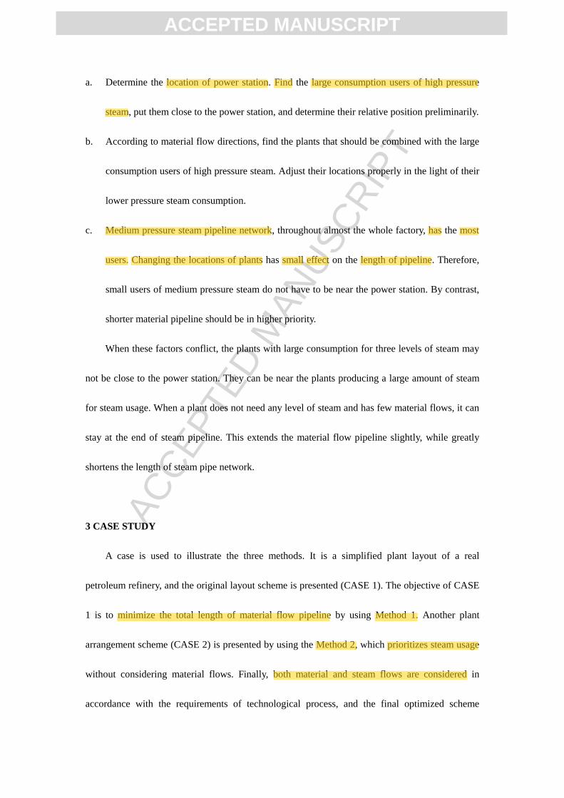
a. Determine the location of power station. Find the large consumption users of high pressure
steam, put them close to the power station, and determine their relative position preliminarily.
b. According to material flow directions, find the plants that should be combined with the large
consumption users of high pressure steam. Adjust their locations properly in the light of their
lower pressure steam consumption.
c. Medium pressure steam pipeline network, throughout almost the whole factory, has the most
users. Changing the locations of plants has small effect on the length of pipeline. Therefore,
small users of medium pressure steam do not have to be near the power station. By contrast,
shorter material pipeline should be in higher priority.
When these factors conflict, the plants with large consumption for three levels of steam may
not be close to the power station. They can be near the plants producing a large amount of steam
for steam usage. When a plant does not need any level of steam and has few material flows, it can
stay at the end of steam pipeline. This extends the material flow pipeline slightly, while greatly
shortens the length of steam pipe network.
3 CASE STUDY
A case is used to illustrate the three methods. It is a simplified plant layout of a real
petroleum refinery, and the original layout scheme is presented (CASE 1). The objective of CASE
1 is to minimize the total length of material flow pipeline by using Method 1. Another plant
arrangement scheme (CASE 2) is presented by using the Method 2, which prioritizes steam usage
without considering material flows. Finally, both material and steam flows are considered in
accordance with the requirements of technological process, and the final optimized scheme
ACC
EPTE
D M
ANU
SCR
IPT
ACCEPTED MANUSCRIPT
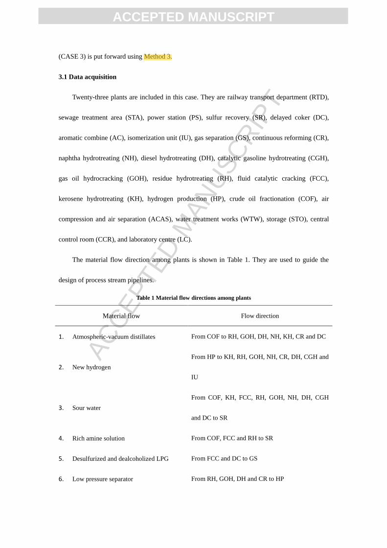
(CASE 3) is put forward using Method 3.
3.1 Data acquisition
Twenty-three plants are included in this case. They are railway transport department (RTD),
sewage treatment area (STA), power station (PS), sulfur recovery (SR), delayed coker (DC),
aromatic combine (AC), isomerization unit (IU), gas separation (GS), continuous reforming (CR),
naphtha hydrotreating (NH), diesel hydrotreating (DH), catalytic gasoline hydrotreating (CGH),
gas oil hydrocracking (GOH), residue hydrotreating (RH), fluid catalytic cracking (FCC),
kerosene hydrotreating (KH), hydrogen production (HP), crude oil fractionation (COF), air
compression and air separation (ACAS), water treatment works (WTW), storage (STO), central
control room (CCR), and laboratory centre (LC).
The material flow direction among plants is shown in Table 1. They are used to guide the
design of process stream pipelines.
Table 1 Material flow directions among plants
Material flow Flow direction
1. Atmospheric-vacuum distillates From COF to RH, GOH, DH, NH, KH, CR and DC
2. New hydrogen
From HP to KH, RH, GOH, NH, CR, DH, CGH and
IU
3. Sour water
From COF, KH, FCC, RH, GOH, NH, DH, CGH
and DC to SR
4. Rich amine solution From COF, FCC and RH to SR
5. Desulfurized and dealcoholized LPG From FCC and DC to GS
6. Low pressure separator From RH, GOH, DH and CR to HP

ACC
EPTE
D M
ANU
SCR
IPT
ACCEPTED MANUSCRIPT
7. LPG From FCC to HP
8. Fractionator bottom oil From NH to CR; From RH to FCC
9. Tail oil From GOH to FCC
10. FCC gasoline From FCC to CGH
11. Heavy naphtha From GOH to CR
12. Light naphtha From NH to IU
13. Non-aromatics From AC to IU
14. Reforming hydrogen From AC to CR
15. Depentanizer bottom oil From CR to AC
16. Sewage From SR to STA
The steam system balance for the petroleum refinery is illustrated in Fig. 1. It is used to guide
the design of steam pipelines.
Fig. 1. Steam system balance diagram.
3.2 Calculation for pipeline length
We simplify the calculation of the length of pipe network. Each plant is a point, ignoring its
3.5MPa
1.0MPa
0.4MPa
CR&AC
COF RH DC DHCR&AC
SR loss
165t/h 203t/h
203t/h
94t/h
94t/hCOF DCCR&AC
GOH
99t/h 273t/h 75t/h 107t/h
HP FCC SR
GOHCR&AC
FCCDCDH
RHCR&AC
10t/h 19t/h 7t/h 12t/h
42t/h 3t/h 5t/h 47t/h 20t/h 23t/h
COF
13t/h
loss
8t/h
SR
30t/h
CR&AC
35t/h
DC
4t/h
FCC
75t/h
GOH
21t/h
RH
3t/h
others
59t/h
CGH
16t/h
STO
30t/h
IU
20t/h
165t/hCOF SRCR&AC
RH
24t/h 56t/h 38t/h 17t/h
24t/h
24t/h
COF
13t/h
RH
9t/h
IU
47t/h
SR
225t/h
loss
12t/h
HP
18t/h
63t/h
52t/h
4t/h
ACC
EPTE
D M
ANU
SCR
IPT
ACCEPTED MANUSCRIPT
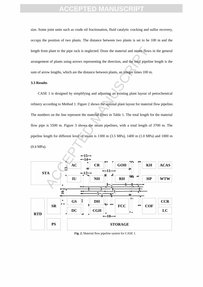
size. Some joint units such as crude oil fractionation, fluid catalytic cracking and sulfur recovery,
occupy the position of two plants. The distance between two plants is set to be 100 m and the
length from plant to the pipe rack is neglected. Draw the material and steam flows in the general
arrangement of plants using arrows representing the direction, and the total pipeline length is the
sum of arrow lengths, which are the distance between plants, an integer times 100 m.
3.3 Results
CASE 1 is designed by simplifying and adjusting an existing plant layout of petrochemical
refinery according to Method 1. Figure 2 shows the optimal plant layout for material flow pipeline.
The numbers on the line represent the material flows in Table 1. The total length for the material
flow pipe is 5500 m. Figure 3 shows the steam pipelines, with a total length of 3700 m. The
pipeline length for different level of steam is 1300 m (3.5 MPa), 1400 m (1.0 MPa) and 1000 m
(0.4 MPa).
Fig. 2. Material flow pipeline system for CASE 1.
3
54
1
6
16
78
2
8
1514
13
RH
FCC
DC
GOH KH
DH
CGH
NH
CRAC
IU HP
GS
SR
STA
STORAGE
CCR
RTD
COF
PS
LC
ACAS
WTW
9
11

ACC
EPTE
D M
ANU
SCR
IPT
ACCEPTED MANUSCRIPT
Fig. 3. Steam pipeline system for CASE 1.
CASE 2 is designed using Method 2. The specific layout steps are as follows.
According to the situation of railway, RTD is in the west of the refinery. PS is at the edge of
the factory, connected to RTD to facilitate the fuel transportation and reduce the dust pollution. To
be close to more workshops simultaneously, it locates in the northwest, without linking with the
large tank farm of steam consumption. COF, FCC, RH, GOH, SR, AC and CR are large users of
3.5 MPa and 1.0 MPa steams, so they are near the power plant according to the usage of steam
level. Among them, FCC is the largest gas producer, so it may be moved eastward appropriately
for providing steam to other plants, as well as reducing the pressure drop loss. AC and CR use the
most 3.5 MPa steam and are close to FCC. COF needs a lot of three levels of steam, so it is also
near PS. In addition, RH and GOH are near PS as far as possible because they also need lots of
high pressure steam. Other high pressure steam users, DC and DH, are in the vicinity of FCC to
make the high pressure steam pipe shortest. For medium pressure steam users IU and CGH, they
are near AC and CR. For 0.3 MPa steam users, HP is near CR. IU and HP are near AC and CR,
CGH is near DC. This layout can give the shortest length of medium pressure steam and low
pressure steam network. Storage covers a large area and uses medium pressure steam, so it is in
0.4MPa
RH
FCC
DC
GOH KH
DH
CGH
NH
CRAC
IU HP
GS
SR
STA
STORAGE
CCR
RTD
COF
PS
LC
ACAS
WTW
1.0MPa
3.5MPa

ACC
EPTE
D M
ANU
SCR
IPT
ACCEPTED MANUSCRIPT
the broad south of refinery. STA should be on the edge of refinery with low-lying area, so it is in
the southwest. CCR and LC are on the east of factory, near the roads. GS and NH should be far
away from dust, so they are near CCR and LC. Other plants, KH, ACAS, and WTW, are in the rest
of positions.
The optimized plant arrangement scheme of CASE 2 is shown in Figs. 4 and 5. Figure 4
shows the material flow pipeline network. Compared with CASE 1, the material flow pipeline
network of CASE 2 is more complicated, with a total length of 6900 m. The total length of steam
pipe is much shorter, as shown in Fig. 5. It is 2900 m. These results are in accordance with the
expectation. Besides, the pipeline length for different level of steam is 1000 m (3.5 MPa), 1300 m
(1.0 MPa) and 600 m (0.4 MPa).
Fig. 4. Material flow pipeline system for CASE 2.
14
8
4
13
2
7
9
10
11
12
8
16
RH
FCC
DC
GOH
KHDH
CGH
NHCR
AC IU
HP
GS
SR
STORAGE
CCR
RTD
COFPS
LC
ACAS
WTW
STA
15

ACC
EPTE
D M
ANU
SCR
IPT
ACCEPTED MANUSCRIPT
Fig. 5. Steam pipeline system for CASE 2
CASE 3 is designed using Method 3. The specific layout steps are as follows.
Adjust the layout of Figs. 4 and 5. Keep the positions for RTD, STA, STORAGE, CCR, LC,
ACAS and WTW, which have less material and steam flows. The location of PS is the optimal and
does not need adjustment. Then combine the related plants according to upstream and downstream
relationship of material flow and safety factor in Method 1. GOH and RH should be near HP; AC,
IU, CR and NH are close to each other; SR and DC, FCC and RH are as close as possible; DH,
KH and CGH are also adjacent to each other and better near HP. In this way, the length of material
pipeline is reduced. Considering the steam usage, adjust the positions of binding plants according
to Figs. 4 and 5 for appropriate steam pipeline length. Following the above methods, several
layouts are obtained by comparing a variety of schemes.
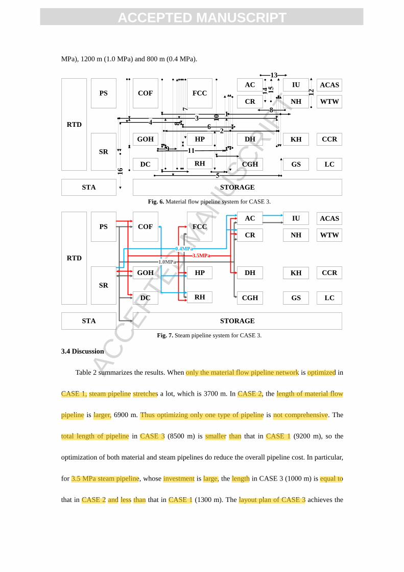
The final layout plan of CASE 3 is shown in Figs. 6 and 7. Figure 6 displays the material
flow pipeline network. The total length is 5500 m, which is smaller than 6900 m in CASE 2. The
same value in CASE 1 and CASE 3 shows very good optimized result. Figure 7 displays that
steam pipelines of different level are as simple as that in CASE 2. The total length of steam
pipelines in CASE 3 is 3000 m. The pipeline length for different level of steam is 1000 m (3.5
RH
FCC
DC
GOH
KHDH
CGH
NHCR
AC IU
HP
GS
SR
STORAGE
CCR
RTD
COFPS
LC
ACAS
WTW
STA
1.0MPa
3.5MPa
0.4MPa
ACC
EPTE
D M
ANU
SCR
IPT
ACCEPTED MANUSCRIPT
MPa), 1200 m (1.0 MPa) and 800 m (0.4 MPa).
Fig. 6. Material flow pipeline system for CASE 3.
Fig. 7. Steam pipeline system for CASE 3.
3.4 Discussion
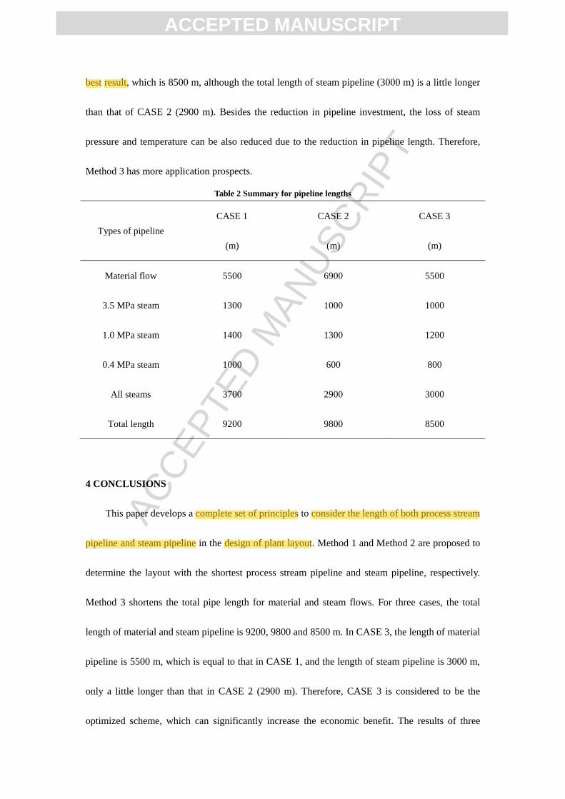
Table 2 summarizes the results. When only the material flow pipeline network is optimized in
CASE 1, steam pipeline stretches a lot, which is 3700 m. In CASE 2, the length of material flow
pipeline is larger, 6900 m. Thus optimizing only one type of pipeline is not comprehensive. The
total length of pipeline in CASE 3 (8500 m) is smaller than that in CASE 1 (9200 m), so the
optimization of both material and steam pipelines do reduce the overall pipeline cost. In particular,
for 3.5 MPa steam pipeline, whose investment is large, the length in CASE 3 (1000 m) is equal to
that in CASE 2 and less than that in CASE 1 (1300 m). The layout plan of CASE 3 achieves the
7
14
8
12
2
8
9
10
RH
FCC
DC
GOH KHDH
CGH
NHCR
AC IU
HP
GS
SR
STA STORAGE
CCR
RTD
COFPS
LC
ACAS
WTW
3
6
13
16
RH
FCC
DC
GOH KHDH
CGH
NHCR
AC IU
HP
GS
SR
STA STORAGE
CCR
RTD
COFPS
LC
ACAS
WTW
1.0MPa
3.5MPa
0.4MPa
ACC
EPTE
D M
ANU
SCR
IPT
ACCEPTED MANUSCRIPT
best result, which is 8500 m, although the total length of steam pipeline (3000 m) is a little longer
than that of CASE 2 (2900 m). Besides the reduction in pipeline investment, the loss of steam
pressure and temperature can be also reduced due to the reduction in pipeline length. Therefore,
Method 3 has more application prospects.
Table 2 Summary for pipeline lengths
Types of pipeline
CASE 1
(m)
CASE 2
(m)
CASE 3
(m)
Material flow 5500 6900 5500
3.5 MPa steam 1300 1000 1000
1.0 MPa steam 1400 1300 1200
0.4 MPa steam 1000 600 800
All steams 3700 2900 3000
Total length 9200 9800 8500
4 CONCLUSIONS
This paper develops a complete set of principles to consider the length of both process stream
pipeline and steam pipeline in the design of plant layout. Method 1 and Method 2 are proposed to
determine the layout with the shortest process stream pipeline and steam pipeline, respectively.
Method 3 shortens the total pipe length for material and steam flows. For three cases, the total
length of material and steam pipeline is 9200, 9800 and 8500 m. In CASE 3, the length of material
pipeline is 5500 m, which is equal to that in CASE 1, and the length of steam pipeline is 3000 m,
only a little longer than that in CASE 2 (2900 m). Therefore, CASE 3 is considered to be the
optimized scheme, which can significantly increase the economic benefit. The results of three
ACC
EPTE
D M
ANU
SCR
IPT
ACCEPTED MANUSCRIPT
cases show that the steam pipe network optimization in process plant layout is very meaningful.
The methodologies proposed can help to put forward optimized plant layout plan. Further work is
needed to optimize the layout of petrochemical plants with steam system using mathematical
programming method.
REFERENCES
1 House, F. F., “An engineer’s guide to process-plant layout”, Chemical Engineering, 76(16), 120-128 (1969).
2 Kern, R., “How to manage plant design to obtain minimum cost”, Chemical Engineering, 84(11), 130-136
(1977).
3 Kaura, M., L., “Plot plans must include safety”, Hydrocarbon Processing, 59(7), 183—194(1980).
4 Kern, R., “Layout arrangements for distillation columns”, Chemical Engineering, 84(17), 153–160(1977).
5 Kern, R., “How to find the optimum layout for heat exchangers”, Chemical Engineering, 84(19), 169—
177(1977).
6 Kern, R., “Arrangements of process and storage vessels”, Chemical Engineering, 84(24), 93—99(1977).
7 Kern, R., “How to get the best process-plant layouts for pumps and compressors”, Chemical Engineering,
84(26), 131—140(1977).
8 Kern, R., “Space requirements and layout for process furnaces”, Chemical Engineering, 85(5), 117—
122(1978).
9 Kern, R., “Instrument arrangements for ease of maintenance and convenient operation”, Chemical Engineering,
85(9), 127—134(1978).
10 Georgiadis, M. C., Macchietto, S., “Layout of process plants: a novel approach”, Computers and Chemical
Engineering Supplement, 21, S337—S342(1997).
11 Tarkesh, H., Atighehchian, A., Nookabadi, A.S., “Facility layout design using virtual multi-agent system”,
Journal of Intelligent Manufacturing, 20(4), 347—357(2009).
12 Shang, J., Kuppusamy, S., “Simulated annealing heuristic for the dynamic facility layout problem”, Computers
& Operations Research, 33(8), 2431—2444(2006).
13 Hillier, F., S., “Quantitative tools for plant layout analysis”, Journal of Industrial Engineering, 14(1), 33—
40(1963).
14 Skorin-Kapov, J., “Tabu search applied to the quadratic assignment problem”, ORSA Journal on Computer, 2(1),
ACC
EPTE
D M
ANU
SCR
IPT
ACCEPTED MANUSCRIPT
33—45(1990).
15 Chandratre, K., V., Nandurkar, K., N., “Applying genetic algorithm to dynamic layout problem”, International
Journal of Applied Operational Research, 1(3), 1—9(2011).
16 Lin, Q., L., Liu, H., C., Wang, D., J., Liu, L., “Integrating systematic layout planning with fuzzy constraint
theory to design and optimize the facility layout for operating theatre in hospitals”, Journal of Intelligent
Manufacturing, 26(1), 87—95(2015).
17 Luo, X., Yang, Y., M., Ge, Z., X., Wen, X., S., “Maintainability-based facility layout optimum design of ship
cabin”, International Journal of Production Research, 5(3), 677—694(2015).
18 Allan, S., Tubaileh, “Layout of flexible manufacturing systems based on kinematic constraints of the
autonomous material handling system”, the International Journal of Advanced Manufacturing Technology,
74(9—12), 1521—1537(2014).
19 Penteado, F. D., Ciric, A. R., “An MINLP approach for safe process plant layout”, Industrial and Engineering
Chemistry Research, 35(4), 1354—1361(1996).
20 Wang, Y., F., Wang, W., Feng, X., “Heat integration across plants considering distance factor”, Chemical
Engineering, 35, 25—30(2013).
21 Sinnott, R., K., Song, X., F., Chemical Engineering Design, 4th edition, China petrochemical press, Beijing,
657—668(2009).(in Chinese)
22 D.Baasel, W., Preliminary Chemical Engineering Plant Design, Elsevier North Holland, New York, 141—
158(1980).
23 GB50984-2014, Petrochemical plant layout design specification, China planning press (2014).(in Chinese)
ACC
EPTE
D M
ANU
SCR
IPT
ACCEPTED MANUSCRIPT
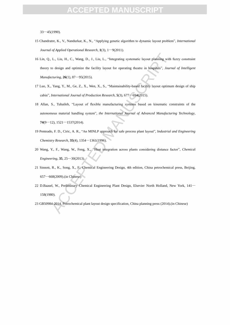
Graphic Abstract
This graph describes the steam pipeline configuration of the optimized plant layout. And the
layout scheme is designed by using the heuristic approach which is proposed in this paper. The
results in the case study show that the total pipeline length, including pipelines of material and
steam, is the shortest in the case of the above graph. They also illustrate that the layout scheme in
this graph, which considers material and steam flows simultaneously, as well as some
environmental protection factors and safety issues, is the most economical and reasonable. Besides,
the methodologies proposed can help to put forward optimized plant layout plan and reduce the
pipeline length significantly.
RH
FCC
DC
GOH KHDH
CGH
NHCR
AC IU
HP
GS
SR
STA STORAGE
CCR
RTD
COFPS
LC
ACAS
WTW
1.0MPa
3.5MPa
0.4MPa


![Informed [Heuristic] Search - University of Delawaredecker/courses/681s07/pdfs/04-Heuristic...Informed [Heuristic] Search Heuristic: “A rule of thumb, simplification, or educated](https://cdn.vdocuments.site/doc/165x107/5aa1e13c7f8b9a84398c48b6/informed-heuristic-search-university-of-delaware-deckercourses681s07pdfs04-heuristicinformed.jpg)


