Download - 9 - Flexural Design for Ultimate Loads

Flexural design for
ultimate loading
Fawad Muzaffar M.Sc. Structures (Stanford University)
Ph.D. Structures (Stanford University)
Civil Engineering
Department

Specified Load Factors
Fawad Muzaffar 2
Load Factors as Specified by ACI-318
Note: Refer to ACI 318-08 for exceptions.
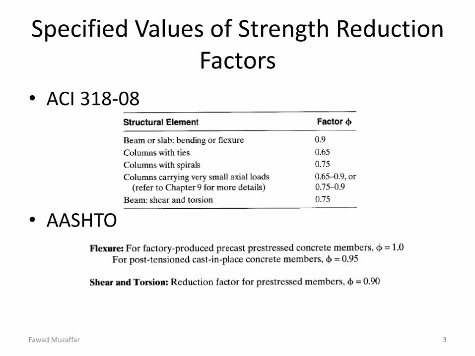
Specified Values of Strength Reduction Factors
• ACI 318-08
• AASHTO
Fawad Muzaffar 3

The Unified Approach for Calculation of Strength Reduction Factors, 𝜙
• Nominal moment capacity is reached when 𝜀𝑐 = 0.003.
• The behavior is tension controlled (or ductile) when 𝜀𝑡 = 0.005.
• If 𝜀𝑡 is small ( as is the case
Fawad Muzaffar 4
for axially loaded members, the behavior of the member will be brittle).
• If 𝜀𝑡 < 𝜀𝑦, the behavior is specified as compression controlled.
• Note: 𝜀𝑡 values above for 𝜀𝑐 = 0.003 can be related to 𝜌/𝜌𝑏 ratios. e.g. 𝜀𝑡 = 0.005 would result in 𝜌 𝜌𝑏 = 0.63

The Unified Approach for Calculation of Strength Reduction Factors, 𝜙
Fawad Muzaffar 5
• Reduction factor as a function of 𝜀𝑡
• Note: The greater the 𝜀𝑡, the more economical will the section be.

Calculation of Nominal Moment-The Strain Compatibility Approach
Fawad Muzaffar 6
• Increase in lateral load results in progressive increase of tensile strain, ultimately cracking at bottom. This happens when
• After M>Mcr significantly , the member starts to behave like reinforced concrete member.
• Before cracking, stresses in concrete at the CGS level have to reduce to zero (i.e. decompression stage)

Calculation of Nominal Moment-The Strain Compatibility Approach
• Strain in Prestressing Steel at Different Stages – Due to Prestressing:
– At Decompression:
– At Ultimate Load:
– Consequently:
– The corresponding stress in prestressing steel can then be evaluated.
• Compression in Concrete
Fawad Muzaffar 7

Calculation of Nominal Moment-The Strain Compatibility Approach
• The Bernoulli Assumptions
• Nominal Moment of Rectangular Sections • If 𝐴𝑠
′ = 0, 𝐶 = 𝑇 yields
Fawad Muzaffar 8

Calculation of Nominal Moment-The Strain Compatibility Approach
• Nominal Moment of Rectangular Sections
– If bonded Reinforcement is to be accounted for, C=T yields
– The internal moment couple can then be written as
• Nominal Moment of Flanged Sections
The internal moment couple can then be written as
Fawad Muzaffar 9

Calculation of Nominal Moment-The Strain Compatibility Approach
• The Solution Algorithm for Rectangular Sections
– Unknowns: 𝑓𝑝𝑠, 𝑓𝑠 & c. Goal: Calculate Mn
– Assume c Calculate 𝜀𝑠 & 𝜀𝑝𝑠 Calculate 𝑓𝑝𝑠, 𝑓𝑠 Evaluate c from
Σ𝐹𝑥 = 0 Check c Iterate if Necessary
or
– Express: 𝜀𝑠 = 𝑓(𝑐) & 𝜀𝑝𝑠 = 𝑓(𝑐) Calculate 𝑓𝑝𝑠, 𝑓𝑠 Constitute
Nonlinear Equation by writing Σ𝐹𝑥 = 0 Solve the nonlinear equation to evaluate c.
• The Solution Algorithm for Flanged Sections – Assume a<tf Check assumption by writing Σ𝐹𝑥 = 0 Analyze as
Rectangular Section if assumption is true.
– If a>tf Correct the assumption and analyze
section by adopting a T section.
Fawad Muzaffar 10
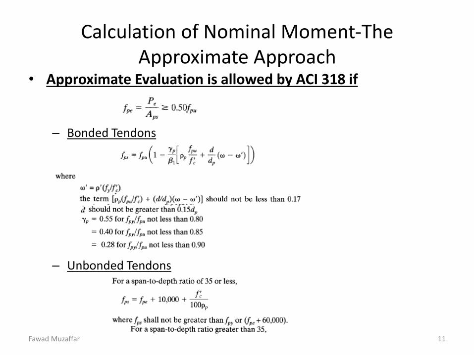
Calculation of Nominal Moment-The Approximate Approach
• Approximate Evaluation is allowed by ACI 318 if
– Bonded Tendons
– Unbonded Tendons
Fawad Muzaffar 11

Design for Ultimate Strength – Reinforcement Limits
• Minimum Values of Reinforcement Index – Definition
– If percentage of reinforcement is
too small, section will fail premat-
-urely as soon as Mu>Mcr.
– The total amount of pre-stressed &
non-prestressed reinforcement req-
uired by ACI should result in
𝑀𝑢 ≥ 1.2 𝑀𝑐𝑟
Exception: If Mn > 2 ×𝑀𝑢 and Vn > 2 × 𝑉𝑢
Fawad Muzaffar 12

Design for Ultimate Strength – Reinforcement Limits
• Minimum area of bonded non-prestressed reinforcement in beams should be calculated using
• Maximum Reinforcement – If percentage of longitudinal reinforcement is large enough, brittle
failure will result.
– To ensure ductile failure, ACI specifies that 𝜀𝑡 ≥ 0.005 at ultimate load.
– In prestressed members, it is not always possible to ensure an under-reinforced behavior because
i) Serviceability Requirements ii) Absence of yield plateau of prestressed steel
Fawad Muzaffar 13

Design for Ultimate Strength – Reinforcement Limits
• To ensure ductile behavior at ultimate load, the reinforcement index is limited to – For Rectangular Sections with Prestressing Steel only:
– For Rectangular Sections with + and –ve bonded Steel:
– For Flange Sections:
where
– Note that for rectangular section
Fawad Muzaffar 14

Design for Ultimate Strength – Reinforcement Limits
– For flange section
– For over-reinforced prestressed beams, section B.18.8.2 of the code specifies
– Use Empirical Relationship to evaluate Mn of Over reinforced Beams
i) Rectangular Section: ii) Flanged Section:
Fawad Muzaffar 15

Evaluation of Nominal Moment of Non-Bonded Prestressed Members
• Un-bonded Tendons – Un-grouted Tendons or Asphalt Coated Tendons.
– Stress Concentration do not exist at crack locations of un-bonded Tendons.
– A lesser number of wider cracks exist in un-bonded prestressed members.
– Bonded reinforcement is more important for members with un-bonded tendons as compared to bonded members.
– Bonded reinforcement contributes significantly to increasing the moment strength capacity of the section.
– The bonded reinforcement at the bottom will always be yielding at ultimate moment.
– The expressions presented for bonded prestressed members are equally applicable for evaluation of nominal moment of un-bonded members.
Fawad Muzaffar 16


