Download - 802SC
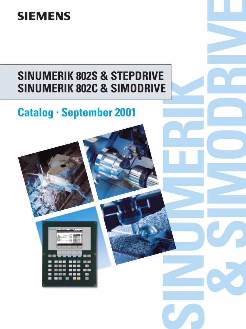
SINUMERIK 802S & STEPDRIVESINUMERIK 802C & SIMODRIVE
Catalog · September 2001
Trademarks / Internet
® SIMATIC, SIMODRIVE, SINUMERIK and STEPDRIVE are Siemens registered trademarks.All other products and system names in this catalogare (registered) trademarks of their respectived owners and must be treated accordingly.
Visit our Automation and Drives Technology site in Internet: http://www.siemens.de/automation
Related Catalog
SINUMERIK & SIMODRIVEAutomation Systemsfor Machine Tools
Order No.:E86060-K4460-A101-A8-7600
NC 60
Automation & DrivesThe Entire Product Rangeon CD ROM
Order No.:E86060-D4001-A110-B5-7600
CA 01
s
Automation Systems forMachine Tools
Catalog · September 2001Supersedes:SINUMERIK 802S/802C Catalog · Sept. 2000
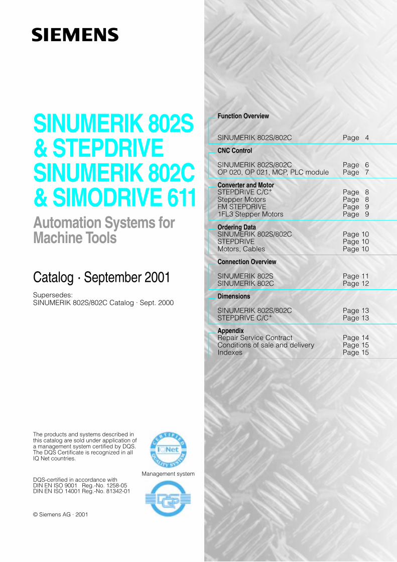
SINUMERIK 802S& STEPDRIVESINUMERIK 802C& SIMODRIVE 611
The products and systems described inthis catalog are sold under application ofa management system certified by DQS.The DQS Certificate is recognized in allIQ Net countries.
Management systemDQS-certified in accordance withDIN EN ISO 9001 Reg.-No. 1258-05DIN EN ISO 14001 Reg.-No. 81342-01
© Siemens AG · 2001
Function Overview
SINUMERIK 802S/802C Page 4
CNC Control
SINUMERIK 802S/802C Page 6OP 020, OP 021, MCP, PLC module Page 7
Converter and MotorSTEPDRIVE C/C+ Page 8Stepper Motors Page 8FM STEPDRIVE Page 91FL3 Stepper Motors Page 9
Ordering DataSINUMERIK 802S/802C Page 10STEPDRIVE Page 10Motors, Cables Page 10
Connection Overview
SINUMERIK 802S Page 11SINUMERIK 802C Page 12
Dimensions
SINUMERIK 802S/802C Page 13STEPDRIVE C/C+ Page 13
AppendixRepair Service Contract Page 14Conditions of sale and delivery Page 15Indexes Page 15
Siemens Catalog SINUMERIK 802S/802C · September 20014
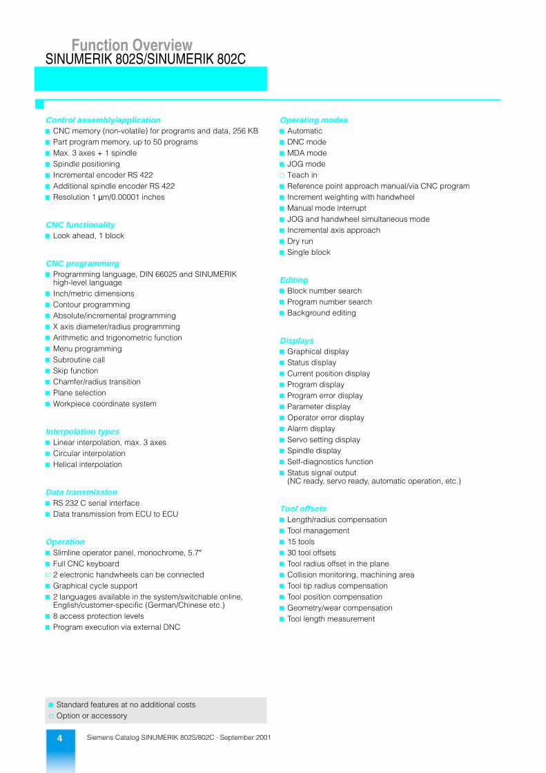
Function OverviewSINUMERIK 802S/SINUMERIK 802C
�
Control assembly/application7 CNC memory (non-volatile) for programs and data, 256 KB7 Part program memory, up to 50 programs7 Max. 3 axes + 1 spindle7 Spindle positioning7 Incremental encoder RS 4227 Additional spindle encoder RS 4227 Resolution 1 µm/0.00001 inches
CNC functionality7 Look ahead, 1 block
CNC programming7 Programming language, DIN 66025 and SINUMERIK
high-level language7 Inch/metric dimensions7 Contour programming7 Absolute/incremental programming7 X axis diameter/radius programming7 Arithmetic and trigonometric function7 Menu programming 7 Subroutine call7 Skip function7 Chamfer/radius transition 7 Plane selection7 Workpiece coordinate system
Interpolation types7 Linear interpolation, max. 3 axes7 Circular interpolation7 Helical interpolation
Data transmission7 RS 232 C serial interface 7 Data transmission from ECU to ECU
Operation7 Slimline operator panel, monochrome, 5.7″7 Full CNC keyboardc 2 electronic handwheels can be connected7 Graphical cycle support7 2 languages available in the system/switchable online,
English/customer-specific (German/Chinese etc.)7 8 access protection levels7 Program execution via external DNC
7 Standard features at no additional costsc Option or accessory
Operating modes7 Automatic7 DNC mode7 MDA mode7 JOG modec Teach in7 Reference point approach manual/via CNC program7 Increment weighting with handwheel7 Manual mode interrupt7 JOG and handwheel simultaneous mode7 Incremental axis approach7 Dry run7 Single block
Editing7 Block number search7 Program number search7 Background editing
Displays7 Graphical display7 Status display7 Current position display7 Program display7 Program error display7 Parameter display7 Operator error display7 Alarm display7 Servo setting display7 Spindle display7 Self-diagnostics function7 Status signal output
(NC ready, servo ready, automatic operation, etc.)
Tool offsets7 Length/radius compensation7 Tool management7 15 tools7 30 tool offsets7 Tool radius offset in the plane7 Collision monitoring, machining area7 Tool tip radius compensation7 Tool position compensation7 Geometry/wear compensation7 Tool length measurement
Function Overview
�
Siemens Catalog SINUMERIK 802S/802C · September 2001 5
Function OverviewSINUMERIK 802S/SINUMERIK 802C
Zero offsets translational/rotary7 Zero offsets, adjustable, max. 47 Zero offsets, programmable
Axis monitoring7 Limit switch monitoring7 2 software limit switches7 Contour monitoring7 Position monitoring7 Clamping monitoring
Compensation7 Stored leadscrew error compensation7 Backlash compensation7 Measuring system error compensation7 Drift compensation for analog set points
Axis functions7 Velocity (max. default 100,000 mm/min / 40,000 inch/min)7 Feedrate override, 0% to 120%7 Feedrate per min7 Feedrate per revolution7 Tangential velocity constant control 7 Jerk limitation7 JOG override
Auxiliary functions7 Miscellaneous function M (2 digit)7 Max. 3 auxiliary functions per block
Spindle functions7 Spindle speed, programmable (max. 999,999.9 rpm)7 Spindle override 0% to 120%7 5 gear stages7 Automatic gear stage selection7 Oriented spindle stop7 Constant cutting speed7 Thread cutting7 Tapping/rigid tapping
7 Standard features at no additional costsc Option or accessory
Cycles7 Cycles for turning7 Cycles for drilling/milling
PLC area7 SIMATIC S7-200 software CPU7 User memory, 4000 instructions7 Ladder programming 7 Digital inputs/outputs, 16/16c Digital inputs/outputs, 64/64 in 16/16 steps7 1024 flags7 16 timers7 32 counters7 Typical processing time for bit commands 1.8 µs
Diagnostics functions7 Diagnostics basic functions7 PLC status
Alarms and messages7 Alarms selectable in the part program7 Alarms and messages from PLC
Start-up7 Start-up tools, running on external PC7 Series start-up via serial interface
Manual machine with OP 021The manual machine version contains in additionthe following functions:7 Constant oriented spindle stop for material change7 Threading with constant cut profile at working spindle7 Cutting of multiple threads7 Cutting of conic threads7 Cutting of transversal thread7 Limit stop turning in X and Z axis7 Conic turning over the complete working area7 Repair thread cutting
�
Siemens Catalog SINUMERIK 802S/802C · September 20016
CNC Control
NC section ECU
SINUMERIK 802S/SINUMERIK 802C
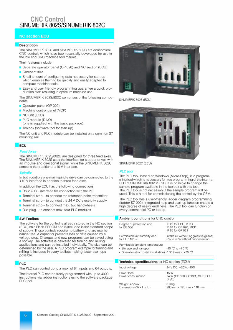
�DescriptionThe SINUMERIK 802S and SINUMERIK 802C are economical CNC controls which have been esentially developed for use in the low end CNC machine tool market.
Their features include:7 Separate operator panel (OP 020) and NC section (ECU)7 Compact size7 Small amount of configuring data necessary for start up –
which enables them to be quickly and easily adapted to compact machine tools.
7 Easy and user friendly programming guarantee a quick pro-duction start resulting in optimum machine use.
The SINUMERIK 802S/802C comprises of the following compo-nents:7 Operator panel (OP 020)7 Machine control panel (MCP)7 NC unit (ECU)7 PLC module (D I/O)
(one is supplied with the basic package)7 Toolbox (software tool for start up)
The NC unit and PLC module can be installed on a common S7 mounting rail.
� ECU
Feed AxesThe SINUMERIK 802S/802C are designed for three feed axes. The SINUMERIK 802S uses the interface for stepper drives with an impulse and directional signal, while the SINUMERIK 802C contains the traditional ±10 V interface.
SpindleIn both controls one main spindle drive can be connected to the ±10 V interface in addition to three feed axes.
In addition the ECU has the following connections:7 RS 232 C – interface for connection with the PC7 Terminal strip – to connect the reference point transmitter7 Terminal strip – to connect the 24 V DC electricity supply7 Terminal strip – to connect max. two handwheels7 Bus plug – to connect max. four PLC modules
� SW-ToolboxThe software for the control is already stored in the NC section (ECU) on a Flash-EPROM and is included in the standard scope of supply. These controls require no battery and are mainte-nance free. A capacitor prevents loss of data caused by a voltage drop. Changes and new programs can be saved using a softkey. The software is delivered for turning and milling applications and can be installed individually. The size can be determined by the user. A PLC program example for turning and milling is included in every toolbox making faster start-ups possible.
� PLCThe PLC can control up to a max. of 64 inputs and 64 outputs.
The internal PLC can be freely programmed with up to 4000 instructions via ladder instructions using the software package PLC tool.
SINUMERIK 802C (ECU)
PLC toolThe PLC tool, based on Windows (Micro-Step), is a program-ming tool which is necessary for free programming of the internal PLC of SINUMERIK 802S/802C. It is possible to change the sample program available in the toolbox with this tool. The PLC tool is not necessary if the sample program will be used. This is a tool for commissioning the control by the OEM.
The PLC tool has a user-friendly ladder diagram programming (ladder S7-200). Integrated help and start-up function enable a high degree of user-friendliness. The PLC tool can function on every commercial PC or laptop.
Ambient conditions for CNC control
Degree of protection acc. to IEC 536
IP 20 for ECU, D I/OIP 64 for OP 020, MCPIP 65 for OP 021
Permissible air humidity acc. to IEC 1131-2
intake air without aggressive gases; 5% to 95% without condensation
Permissible ambient temperatureStorage and transport -40 °C to +70 °COperation (horizontal installation) 0 °C to max. +55 °C
Technical specifications for NC section (ECU)
Input voltage 24 V DC; +20%, -15%
Power lossPower consumption
15 W24 W (OP 020, OP 021, MCP, ECU, D I/O)
Weight, approx.Dimensions (W x H x D)
0.9 kg200 mm x 125 mm x 118 mm
CNC Control
SINUMERIK 802S (ECU)
Siemens Catalog SINUMERIK 802S/802C · September 2001 7
CNC ControlSINUMERIK 802S/SINUMERIK 802C
OP 020, MCP, OP 021PLC module
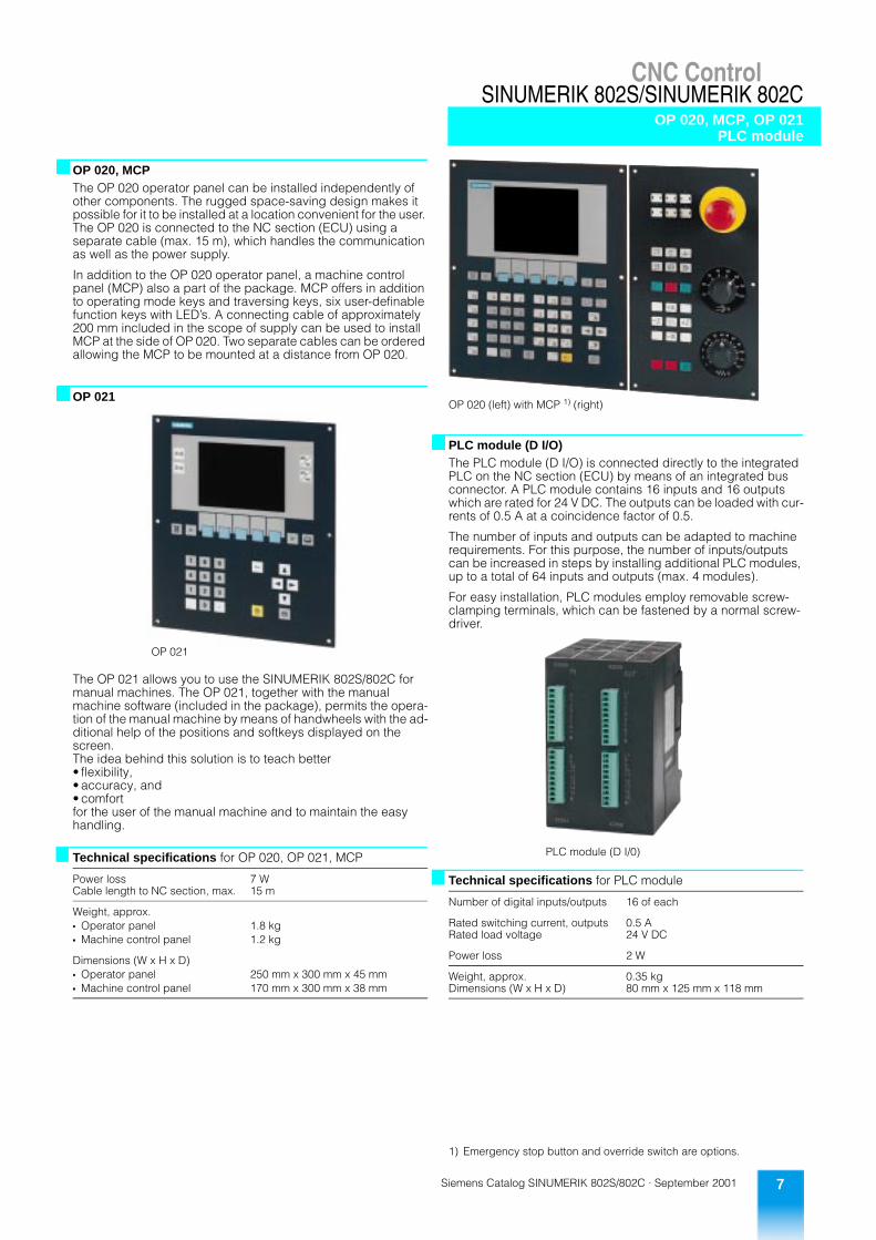
�OP 020, MCPThe OP 020 operator panel can be installed independently of other components. The rugged space-saving design makes it possible for it to be installed at a location convenient for the user. The OP 020 is connected to the NC section (ECU) using a separate cable (max. 15 m), which handles the communication as well as the power supply.
In addition to the OP 020 operator panel, a machine control panel (MCP) also a part of the package. MCP offers in addition to operating mode keys and traversing keys, six user-definable function keys with LED’s. A connecting cable of approximately 200 mm included in the scope of supply can be used to install MCP at the side of OP 020. Two separate cables can be ordered allowing the MCP to be mounted at a distance from OP 020.
�OP 021
The OP 021 allows you to use the SINUMERIK 802S/802C for manual machines. The OP 021, together with the manual machine software (included in the package), permits the opera-tion of the manual machine by means of handwheels with the ad-ditional help of the positions and softkeys displayed on the screen.The idea behind this solution is to teach better• flexibility,• accuracy, and• comfortfor the user of the manual machine and to maintain the easy handling.
OP 021
Technical specifications for OP 020, OP 021, MCP
Power lossCable length to NC section, max.
7 W15 m
Weight, approx.Operator panel 1.8 kgMachine control panel 1.2 kg
Dimensions (W x H x D)Operator panel 250 mm x 300 mm x 45 mmMachine control panel 170 mm x 300 mm x 38 mm
�PLC module (D I/O)The PLC module (D I/O) is connected directly to the integrated PLC on the NC section (ECU) by means of an integrated bus connector. A PLC module contains 16 inputs and 16 outputs which are rated for 24 V DC. The outputs can be loaded with cur-rents of 0.5 A at a coincidence factor of 0.5.
The number of inputs and outputs can be adapted to machine requirements. For this purpose, the number of inputs/outputs can be increased in steps by installing additional PLC modules, up to a total of 64 inputs and outputs (max. 4 modules).
For easy installation, PLC modules employ removable screw-clamping terminals, which can be fastened by a normal screw-driver.
1) Emergency stop button and override switch are options.
OP 020 (left) with MCP 1) (right)
PLC module (D I/0)
Technical specifications for PLC module
Number of digital inputs/outputs 16 of each
Rated switching current, outputsRated load voltage
0.5 A24 V DC
Power loss 2 W
Weight, approx.Dimensions (W x H x D)
0.35 kg80 mm x 125 mm x 118 mm
Siemens Catalog SINUMERIK 802S/802C · September 20018
Converter and MotorsSTEPDRIVE C/C , Stepper Motors
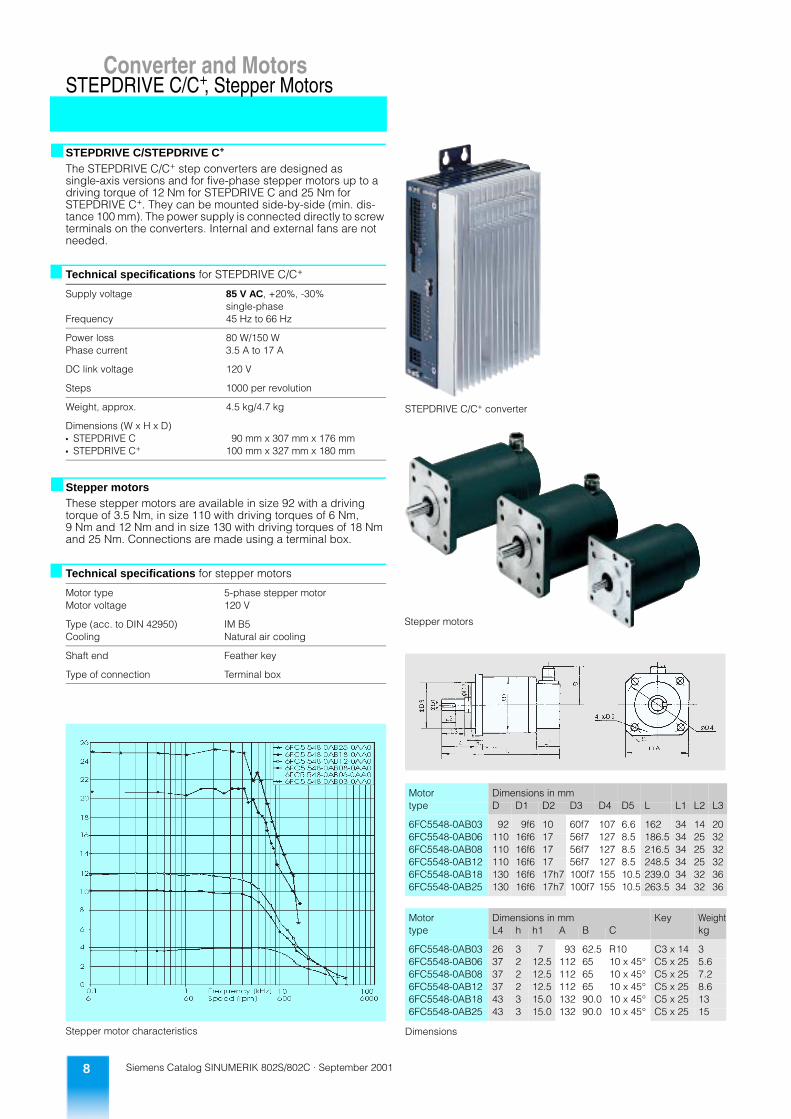
� STEPDRIVE C/STEPDRIVE C+
The STEPDRIVE C/C+ step converters are designed as single-axis versions and for five-phase stepper motors up to a driving torque of 12 Nm for STEPDRIVE C and 25 Nm for STEPDRIVE C+. They can be mounted side-by-side (min. dis-tance 100 mm). The power supply is connected directly to screw terminals on the converters. Internal and external fans are not needed.
� Stepper motorsThese stepper motors are available in size 92 with a driving torque of 3.5 Nm, in size 110 with driving torques of 6 Nm,9 Nm and 12 Nm and in size 130 with driving torques of 18 Nm and 25 Nm. Connections are made using a terminal box.
Stepper motor characteristics
Technical specifications for STEPDRIVE C/C+
Supply voltage 85 V AC, +20%, -30%single-phase
Frequency 45 Hz to 66 Hz
Power loss 80 W/150 WPhase current 3.5 A to 17 A
DC link voltage 120 V
Steps 1000 per revolution
Weight, approx. 4.5 kg/4.7 kg
Dimensions (W x H x D)STEPDRIVE C 90 mm x 307 mm x 176 mmSTEPDRIVE C+ 100 mm x 327 mm x 180 mm
Technical specifications for stepper motors
Motor type 5-phase stepper motorMotor voltage 120 V
Type (acc. to DIN 42950) IM B5Cooling Natural air cooling
Shaft end Feather key
Type of connection Terminal box
STEPDRIVE C/C+ converter
Dimensions
Stepper motors
Motor Dimensions in mmtype D D1 D2 D3 D4 D5 L L1 L2 L3
6FC5548-0AB03 92 9f6 10 60f7 107 6.6 162 34 14 206FC5548-0AB06 110 16f6 17 56f7 127 8.5 186.5 34 25 326FC5548-0AB08 110 16f6 17 56f7 127 8.5 216.5 34 25 326FC5548-0AB12 110 16f6 17 56f7 127 8.5 248.5 34 25 326FC5548-0AB18 130 16f6 17h7 100f7 155 10.5 239.0 34 32 366FC5548-0AB25 130 16f6 17h7 100f7 155 10.5 263.5 34 32 36
Motor Dimensions in mm Key Weighttype L4 h h1 A B C kg
6FC5548-0AB03 26 3 7 93 62.5 R10 C3 x 14 36FC5548-0AB06 37 2 12.5 112 65 10 x 45° C5 x 25 5.66FC5548-0AB08 37 2 12.5 112 65 10 x 45° C5 x 25 7.26FC5548-0AB12 37 2 12.5 112 65 10 x 45° C5 x 25 8.66FC5548-0AB18 43 3 15.0 132 90.0 10 x 45° C5 x 25 136FC5548-0AB25 43 3 15.0 132 90.0 10 x 45° C5 x 25 15
Converter and Motors
+
Siemens Catalog SINUMERIK 802S/802C · September 2001 9
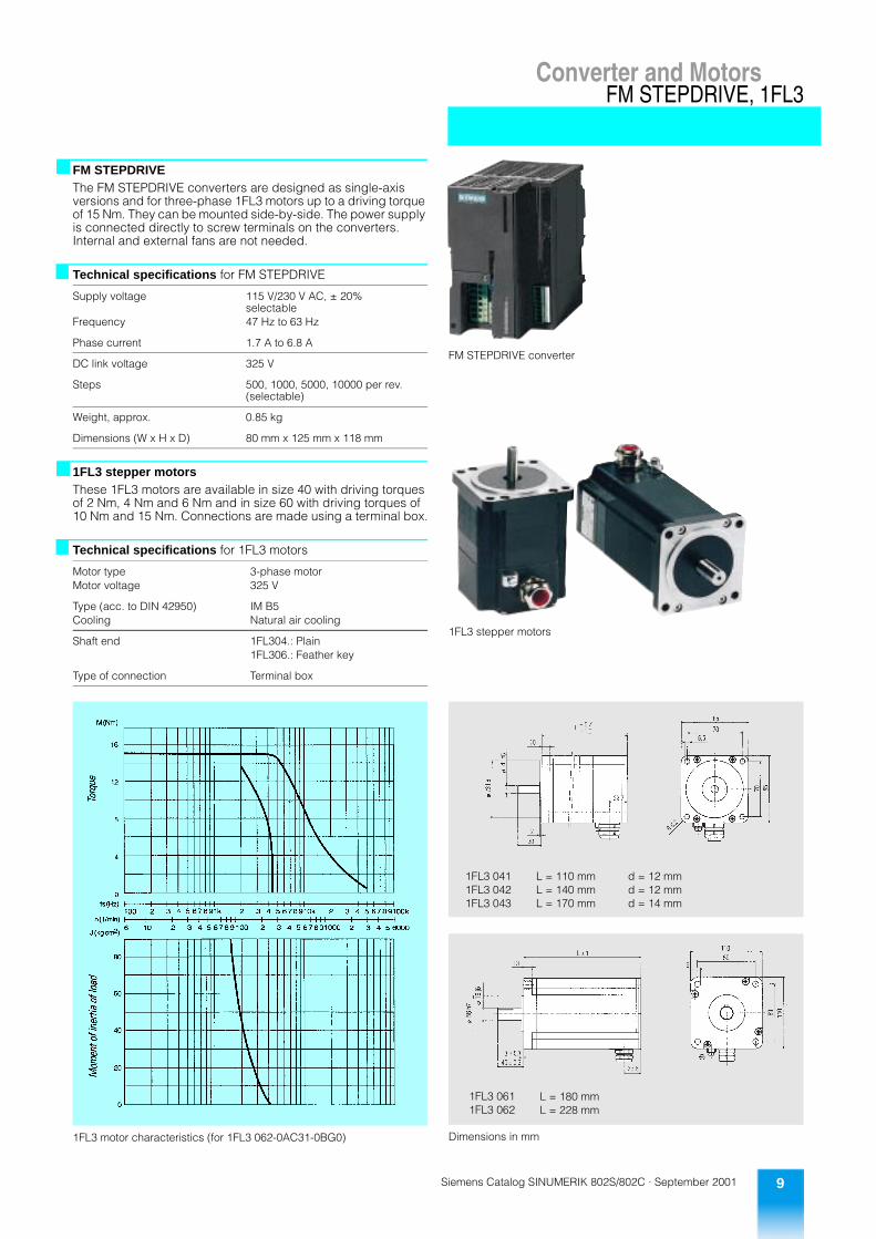
Converter and MotorsFM STEPDRIVE, 1FL3
� FM STEPDRIVEThe FM STEPDRIVE converters are designed as single-axis versions and for three-phase 1FL3 motors up to a driving torque of 15 Nm. They can be mounted side-by-side. The power supply is connected directly to screw terminals on the converters.Internal and external fans are not needed.
� 1FL3 stepper motorsThese 1FL3 motors are available in size 40 with driving torques of 2 Nm, 4 Nm and 6 Nm and in size 60 with driving torques of 10 Nm and 15 Nm. Connections are made using a terminal box.
1FL3 motor characteristics (for 1FL3 062-0AC31-0BG0)
Technical specifications for FM STEPDRIVE
Supply voltage 115 V/230 V AC, ± 20%selectable
Frequency 47 Hz to 63 Hz
Phase current 1.7 A to 6.8 A
DC link voltage 325 V
Steps 500, 1000, 5000, 10000 per rev.(selectable)
Weight, approx. 0.85 kg
Dimensions (W x H x D) 80 mm x 125 mm x 118 mm
Technical specifications for 1FL3 motors
Motor type 3-phase motorMotor voltage 325 V
Type (acc. to DIN 42950) IM B5Cooling Natural air cooling
Shaft end 1FL304.: Plain1FL306.: Feather key
Type of connection Terminal box
FM STEPDRIVE converter
1FL3 stepper motors
Dimensions in mm
1FL3 0411FL3 0421FL3 043
L = 110 mmL = 140 mmL = 170 mm
d = 12 mmd = 12 mmd = 14 mm
1FL3 061 L = 180 mm1FL3 062 L = 228 mm
Siemens Catalog SINUMERIK 802S/802C · September 200110
Ordering DataSINUMERIK 802S/802C
1) For using the standard manual machine PLC software two additionalD I/O modules are necessary.
Ordering data Order No.
SINUMERIK 802S with STEPDRIVE
SINUMERIK 802S 6FC5 500-0AA00-0AA0for stepper drivespackage comprising:
Operator panel (OP 020) Machine control panel (MCP) with connecting cable to operatorpanel for side panel mounting NC section (ECU)PLC module (D I/O) Mounting rail (482 mm) Toolbox (software for start-up)
SINUMERIK 802S-Manual machine 1)
6FC5 500-0AA20-0AA0
for stepper drivespackage comprising:
Operator panel (OP 021) NC section (ECU) PLC module (D I/O) Mounting rail for ECU and D I/OToolbox (software for start-up)
STEPDRIVE C 6FC5 548-0AA00-0AA0converter 1 axis
STEPDRIVE C+ 6FC5 548-0AA02-0AA0converter 1 axis
Stepper motorsDriving torque 3.5 Nm 6FC5 548-0AB03-0AA0Driving torque 6 Nm 6FC5 548-0AB06-0AA0Driving torque 9 Nm 6FC5 548-0AB08-0AA0Driving torque 12 Nm 6FC5 548-0AB12-0AA0Driving torque 18 Nm 6FC5 548-0AB18-0AA0Driving torque 25 Nm 6FC5 548-0AB25-0AA0
FM STEPDRIVE 6SN1 227-2ED10-0HA0converter 1 axis
Sub-D connector 6FC9 348-7HX15-pin socket (mating connector) Packing unit: 3 items
1FL3 stepper motorsDriving torque 2 Nm 1FL3 041-0AC31-0BK0Driving torque 4 Nm 1FL3 042-0AC31-0BK0Driving torque 6 Nm 1FL3 043-0AC31-0BG0Driving torque 10 Nm 1FL3 061-0AC31-0BG0Driving torque 15 Nm 1FL3 062-0AC31-0BG0
Ordering data Order No.
SINUMERIK 802C with SIMODRIVE
SINUMERIK 802C 6FC5 500-0AA11-0AA0for servo drivespackage comprising:
Operator panel (OP 020) Machine control panel (MCP) with connecting cable to operatorpanel for side panel mounting NC section (ECU)PLC module (D I/O) Mounting rail (482 mm) Toolbox (software for start-up)
SINUMERIK 802C-Manual machine 1)
6FC5 500-0AA22-0AA0
for stepper drivespackage comprising:
Operator panel (OP 021) NC section (ECU) PLC module (D I/O) Mounting rail for ECU and D I/OToolbox (software for start-up)
SIMODRIVE 611 components refer to Catalog NC 60
1FT/1FK servo motors refer to Catalog NC 60
Ordering Data
Siemens Catalog SINUMERIK 802S/802C · September 2001 11
Ordering DataSINUMERIK 802S/802C
Ordering data Order No.
Accessories
OP 020 6FC5 503-0AC00-0AA0
OP 021 6FC5 503-0AC22-0AA0
PLC module (D I/O) 6FC5 511-0CA00-0AA0
Override switch for spindle 6FC5 503-0AY04-0AA0
PLC tool PLC programming tool 1) 6FC5 551-0AB00-0BB0
Teach in software option 6FC5 571-0AA01-0BF0
Emergency stop button for MCPActuating element 3SB3 000-1HA20Switch element 3SB3 400-0A
Connecting cables for 802S/802COP 020 ↔ ECU (802S/802C) 6FX5 002-1AA02-1 0OP 020 ↔ MCP(two cables necessary)
6FX5 002-1AA03-1 0
ECU (802S) ↔ STEPDRIVE C/C+ or FM STEPDRIVE (useable up to 3 axes)
6FX5 002-3BA31-1 0
Lengths:1 m3 m5 m7 m
10 m15 m
Motor cablesSTEPDRIVE C/C+ ↔ Stepper motor
6FX5 008-5AA51-1 A0
Motor cablesFM STEPDRIVE ↔ 1FL3 motor 6FX5 008-5AA00-1 A0
Packing drum length:10 m20 m50 m
DocumentationUser guide - Turning 6FC5 598-3AA00-0 P1User guide - Milling 6FC5 598-3AA10-0 P1Diagnostic handbook 6FC5 598-3AA20-0 P1Commissioning guide for SINUMERIK 802S
6FC5 597-2AA00-0 P1
Commissioning guide for SINUMERIK 802C
6FC5 597-3AA20-0 P1
Functioning guide 6FC5 597-3AA10-0 P1DOC ON CDUser and Manufacturer Documentation onCD-ROM with Help tool
6FC5 298-5CA00-0 G2
Language:GermanEnglishFrenchItalianSpanish
1) Necessary till SW 3.0.
AAAABB
BDFHAF
BCF
ABDCE
�Repair service contract (RSV)
Competent consulting and engineering servicesSpeak with our specialists. They would be glad to advise you. Our specialists not only develop user-specific programs and op-erator interfaces, but also customize the NC functionality to your technology. This allows you to distinguish yourself from the com-petition and at the same time reduce the implementation over-head needed for your projects.
CommissioningIt goes without saying that we put the applications developed specifically for your company into operation and help you get started. We also get your machines up and running, regardless of whether they are prototypes or series machines.
Warranty with repair service contractAs machine manufacturer or dealer, our repair service contract makes it possible for you to fulfill your warranty obligations to your customers economically and reliably. It includes on-site corrective maintenance of Siemens components worldwide. See the “RSV Repair Service Contract”.
Field serviceOur qualified field service personnel are, of course, also avail-able even when no service contract has been entered. Our field service representatives correct faults, order spare parts, and ar-range for any needed repairs.
Technical supportDo you need help using our products?We offer both telephone consultations and online support.Our online support provides technical information for many products, including:• FAQs, tips and tricks, downloads• Manuals• Helpful programs and software productshttp://www.siemens.com/automation/sinumerik802
Contact addressesAre you looking for a contact for our wide variety of services? If so, here's the answer!
Technical SupportTelephone: +49 (0) 180 50 50 222Fax: +49 (0) 180 50 50 223
Online Supporthttp://www.siemens.com/automation/support
Field Service GermanyTelephone: +49 (0) 180 50 50 444
Field Service outside GermanyFax: +49 (0) 9131 98-1084
Worldwide service locations on the Internet:http://www.siemens.com/automation/partnerunder Technology/Products/Sectors “CNC Controls and Drives” and under “Field Service”.
Ordering data Order No.
Repair service contractfor Siemens machine-toolcomponents for regionsin groups 1 to 4
6FC8 506- X0 0AA0
Warranty period 1 year 1Warranty period 2 years 2Warranty period 3 years 3Warranty period 4 years 4Warranty period 5 years 5
Master contract RIndividual contract E
0 to 4 measuring circuits 15 measuring circuits 2

Siemens Catalog SINUMERIK 802S/802C · September 200112
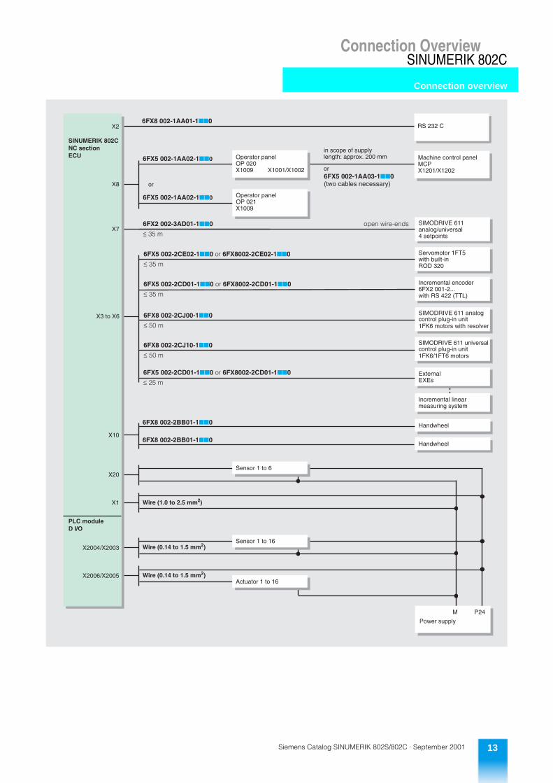
Connection Overview
Connection overview
SINUMERIK 802S
6FX8 002-1AA01-1nn0RS 232 C
6FX5 002-3BA31-1nn0
or
6FX5 002-1AA02-1nn0 Machine control panelMCPX1201/X1202
6FX5 002-1AA03-1nA0(two cables necessary)
6FX5 008-5AA51-1nA0
6FX5 008-5AA51-1nA0
6FX5 008-5AA51-1nA0
Stepper motor
Stepper motor
Stepper motor
6FX5 002-3BA31-1nn01FL3 motor
1FL3 motor
1FL3 motor
6FX8 002-3AB01-1nn0
6FX5 002-2CD01-1nn0 or 6FX8 002-2CD01-1nn0
Spindle motor
Encoder
6FX8 002-2BB01-1nn0
6FX8 002-2BB01-1nn0
Handwheel
Handwheel
Sensor 1 to 6
Wire (1.0 to 2.5 mm2)
Sensor 1 to 16Wire (0.14 to 1.5 mm2)
Actuator 1 to 16Wire (0.14 to 1.5 mm2)
X8
X2
SINUMERIK 802SNC sectionECU
X9
X3
X4
X10
X20
X1
PLC moduleD I/O
X2004/X2003
X2006/X2005
M P24
Power supply
6FX5 008-5AA00-1nA0
6FX5 008-5AA00-1nA0
6FX5 008-5AA00-1nA0
or
in scope of supplylength: approx. 200 mm
Spindle drive
2)
2)
2)
1) With open wire-ends2) Sub-D connector 6FC9 348-7HX
Operator panelOP 020X1009
STEPDRIVE C/C+
STEPDRIVE C/C+
STEPDRIVE C/C+
FM STEPDRIVE
FM STEPDRIVE
FM STEPDRIVE
X1001/X1002
1)
1)
1)
1)
1)
1)
1)
1)
1)
1)
1)
1)
6FX5 002-1AA02-1nn0 Operator panelOP 021X1009
or
Connection Overview
Siemens Catalog SINUMERIK 802S/802C · September 2001 13
Connection OverviewSINUMERIK 802C
Connection overview
6FX8 002-1AA01-1nn0RS 232 C
6FX5 002-1AA02-1nn0 Machine control panelMCPX1201/X1202
6FX5 002-1AA03-1nn0(two cables necessary)
6FX8 002-2BB01-1nn0
6FX8 002-2BB01-1nn0
Handwheel
Handwheel
Sensor 1 to 6
Wire (1.0 to 2.5 mm2)
Sensor 1 to 16Wire (0.14 to 1.5 mm2)
Actuator 1 to 16Wire (0.14 to 1.5 mm2)
X2
X3 to X6
SINUMERIK 802CNC sectionECU
X10
X20
X1
PLC moduleD I/O
X2004/X2003
X2006/X2005
M P24
Power supply
or
in scope of supplylength: approx. 200 mmOperator panel
OP 020X1009 X1001/X1002
X7
6FX5 002-2CE02-1nn0 or 6FX8002-2CE02-1nn0
£ 35 m
6FX5 002-2CD01-1nn0 or 6FX8002-2CD01-1nn0
£ 35 m
6FX8 002-2CJ00-1nn0
£ 50 m
6FX5 002-2CD01-1nn0 or 6FX8002-2CD01-1nn0
£ 25 m
SIMODRIVE 611analog/universal4 setpoints
Servomotor 1FT5with built-inROD 320
Incremental encoder6FX2 001-2...with RS 422 (TTL)
SIMODRIVE 611 analogcontrol plug-in unit1FK6 motors with resolver
ExternalEXEs
6FX2 002-3AD01-1nn0 open wire-ends
£ 35 m
Incremental linearmeasuring system
6FX8 002-2CJ10-1nn0
£ 50 m
SIMODRIVE 611 universalcontrol plug-in unit1FK6/1FT6 motors
X8
6FX5 002-1AA02-1nn0 Operator panelOP 021X1009
or
Siemens Catalog SINUMERIK 802S/802C · September 200114
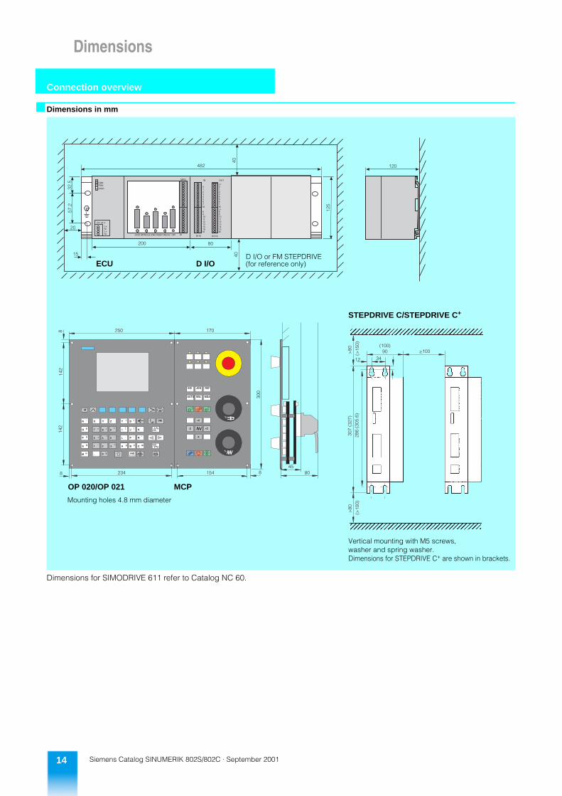
Dimensions
Connection overview
�Dimensions in mm
Dimensions for SIMODRIVE 611 refer to Catalog NC 60.
STEPDRIVE C/STEPDRIVE C+
Mounting holes 4.8 mm diameter
MCP
Vertical mounting with M5 screws,washer and spring washer.Dimensions for STEPDRIVE C+ are shown in brackets.
ECU D I/OD I/O or FM STEPDRIVE(for reference only)
OP 020/OP 021
Dimensions
Siemens Catalog SINUMERIK 802S/802C · September 2001 15
Appendix
� Subject index
�Order No. index
Page Page
Alarms 5Application 4Auxiliary functions 5Axis function 5Axis monitoring 5CNC functionality 4CNC programming 4Compensation 5Connection overview 12, 13Control assembly 4Cycles 5Data transmission 4Diagnostics functions 5Dimensions 14Displays 4ECU 6Editing 4FM STEPDRIVE 9Interpolation types 4
MCP 7Messages 5Offsets 4OP 020, OP 021 7Operating modes 4Operation 4Ordering data 10PLC area 5PLC module 7PLC tool 6PLC 6Repair service contract 11SINUMERIK 802C 6SINUMERIK 802S 6Spindle functions 5Start-up 5STEPDRIVE 8Stepper motors 8, 9SW-Toolbox 6
Type Page Type Page Type Page Type Page
1FL31FL304.-0AC31-.... 101FL306.-0AC31-.... 10
3SB33SB3000-1HA20 113SB3400-0A 116FC526FC5298-5CA00-.... 11
6FC556FC5500-0AA..-.... 106FC5503-0AC2.-.... 116FC5503-0AY04-.... 116FC5511-0CA00-.... 116FC5548-0AA0.-.... 106FC5548-0AB..-.... 106FC5551-0AB00-.... 116FC5571-0AA01-.... 116FC5597-2AA..-.... 116FC5597-3AA..-.... 116FC5598-3AA..-.... 11
6FC86FC8506-... 11
6FC96FC9348-7HX 10
6FX26FX2002-3AD01-.... 13
6FX56FX5002-1AA0.-.... 11, 12, 136FX5002-2CD01-.... 12, 136FX5002-2CE02-.... 136FX5002-3BA31-.... 11, 126FX5008-5AA..-.... 11, 12
6FX86FX8002-1AA01-.... 12, 136FX8002-2BB01-.... 12, 136FX8002-2CD01-.... 12, 136FX8002-2CE02-.... 136FX8002-2CJ00-.... 136FX8002-2CJ10-.... 136FX8002-3AB01-.... 12
6SN126SN1227-2ED10-.... 10
Siemens AGAutomation and Drives GroupMotion Control Systems
Order No.: E86060-K4460-E109-A3-7600Printed in the Federal Republic of GermanyKG K 0901 5.0 16 VOG En/122368
�Conditions of sale and deliverySubject to the General Conditions of Supply and Delivery for Products and Services of the Electrical and Electronics Industry, and to the Delivery and Service Conditions of SINUMERIK.
Export regulationsThe products listed in this catalog may be subject to European/German and/or US export provisions.Any export requiring approval is therefore subject to authoriza-tion by the relevant authorities. For the products listed in this catalog, the following export regulations must be adhered to in accordance with currently valid regulations.AL Number of the German export list
Products with a code other than “N” must be approved for export. The export codes of the respective data medium
must also be adhered to for software products. Goods labeled with “AL not equal to N” are subject to European or German export authorization when beingexported out of the EU.
ECCN Number of US export list(Export Control Classification Number) Products with a code other than “N” require approval forre-export to certain countries. The export codes of the rspective data medium must also be adhered to for soware products.Goods labeled with “ECCN not equal to N” are subject toUS re-export authorization.
Even without a label, or with label “AL: N” or “ECCN: N”, authorization may be required due to the final whereabouts and purpose for which the goods are to be used.The AL and ECCN export codes specified in our confirmations, delivery notes and invoices apply.Subject to change without prior notice.
The technical data, dimensions and weights are subject to change unless otherwise stated on the individual pages of this catalog.The illustrations are for reference only.We reserve the right to adjust the prices and shall charge the prices applying on the date of delivery.Software products are subject to the General Conditions ofSupply of Software Products for Automation Tasks.
Conversion FactorsThe following conversion factors are to be used when converting units given in the Metric system to Imperial measure.1 mm = 0.0394 in 0.1 kg = 3.5274 oz1 cm = 0.3937 in 1.0 kg = 2.2046 lb1 m = 39.3701 in 1 Nm = 8.8508 lb-in1 m = 3.281 ft/1.09 yd
Appendix

Order No.: E86060-K4460-E109-A3-7600
Our address in the Internet:
http://www.siemens.de/automation/sinumerik
Siemens Aktiengesellschaft


