Download - Document2

W
Introduction
This project is based on DTMF technology i.e. dual transmission multi
frequency. Using DTMF here a robot is controlled hence called the mobile
controlled robot. Using DTMF we can be able to control our device from a
very long range only necessary thing is that there should be mobile network.
One can be able to control his home appliances while sitting in his office.
DTMF Mobile ROBOT is a machine that can be controlled with a mobile. In
this project, the robot is controlled by a mobile phone that makes a call to
the mobile phone attached to the robot.
In the course of a call, if any button is pressed, a tone
Corresponding to the button pressed is heard at the other end of the call.
This tone is called "Dual Tone Multiple-Frequency"(DTMF) tone.
The robot perceives this DTMF tone with the help of the phone stacked on
the robot. The received tone is processed by the microcontroller with the
help of DTMF Decoder.
The microcontroller then transmits the signal to the motor driver ICs to
operate the motors & our robot starts moving Conventionally, Wireless-
controlled robots use Rf circuits, which have the drawbacks of limited
working range,
Limited frequency range and the limited control. Use of a mobile phone for
robotic control can overcome these limitations. It provides the advantage of
robust control, working range as large as the coverage area of the service
provider, no interference with other controllers and up to twelve controls.
Page-1

W
WIRELESS CONTROL VIA MOBILE COMMUNICATION
-Use of DTMF signals
WHAT IS DTMF SIGNAL?
The 12 keys on a cell phone (0, 1… 8, 9,*, #) has unique signal associated
with itself. This is DTMF signal.
When the call is on, the pressing of any numerical key leads to generation
of DTMF signal which is audible on the other side.
TRY YOUR SELF!!!
Take any Nokia cell phone (others I haven’t tested), turn on keypad tones,
press any key, the tone your hear is DTMF tone.
Note: Don’t confuse keypad tones with the tone that is heard on other side
while call is on. The tone heard on other side (while call is on) is DTMF tone.
Keypad tones can be different than DTMF tones (as in Samsung that use Sa
Re Ga Ma … tone). It is just Nokia mobile manufacturer that uses DTMF tones
for keypad tones also.
Page-2
W
Hardware Description List of components used :-
1. MT8870 dtmf decoder IC
2. 100k resistor 2pc.
3. 300k resistor 1pc.
4. 3.57945 MHz crystal oscillator
5. 0.1 uf capacitor 2pc.
6. 4 LED
7. Connecting wires....
Working:--‐While the input from the mobile using a headphone is connected b/w the
0.1uf capacitor and the ground, DTMF tones can be Transferred to the
decoder ic(8870) and once The ic is powered up the o/p can be seen by
connecting LED's at Q!, Q2, Q3 and Q4 o/p of the decoder ic.
Page-3

W
The output on the Q1 to Q4 pins of the decoder IC has
been shown in the image.
The o/p of the decoder ic then can be connected to a motor driver ic like
(L298 or L293D) to drive some motors or relays as a switch to operate some
devices remotely as The Mobile phone connected can be called From
anywhere in the world and by pressing The keys the DTMF tones can be
transmitted To the receiving end mobile and hence any Device connected
can be operated globally.
Block Diagram :1
Page-4

W
Figure: a
DTMF TONE
• The DTMF technique outputs distinct representation of 16 common
alphanumeric characters (0-9, A-D, *, #) on the telephone. The lowest
frequency used is 697Hz and the highest frequency used is 1633Hz.
Page-5

W
Block Diagram :2
Table : i
Page-6

W
Figure: b
The MT-8870 is a DTMF Receiver that integrates both band split filter and
decoder functions into a single 18-pin DIP or SOIC package. It is
manufactured using CMOS process technology. The MT-8870 offers low
power consumption (35 mW max) and precise data handling. Its filter section
uses switched capacitor technology for both the high and low group filters
and for dial tone rejection. Its decoder uses digital counting techniques to
detect and decode all 16 DTMF tone pairs into a 4-bit code. Minimal external
components required includes a low-cost 3.579545 MHz color burst crystal, a
timing resistor, and a timing capacitor.
Page-7

W
The filter section is used for separation of the low-group and high group
tones and it is achieved by applying the DTMF signal to the inputs of two
sixth order switched capacitor band pass filters, the bandwidths of which
corresponds to the low and high group frequencies. The filter section also
incorporates notches at 350 and 440 Hz for exceptional dial tone rejection.
Each filter output is followed by a single order switched capacitor filter
section which smoothes the signals prior to limiting. Limiting is performed by
high-gain comparators which are provided with hysteresis to prevent
detection of unwanted low-level signals. The outputs of the comparators
provide full rail logic swings at the frequencies of the incoming DTMF signals.
Following the filter section is a decoder employing digital counting
techniques to determine the frequencies of the incoming tones and to verify
that they correspond to the standard DTMF frequencies
Page-8

W
Test Circuit
Figure: c
Following are the outputs produced by the DTMF decoder when the
respective keys are pressed
Table: ii
Page-9

W
MICRO CONTROLLER:
Micro controller is a programmable logical devise which can be used to control
robots, any appliance. Here we use ATMEGA-16 micro controller in our circuit to
control the robot .At mega 16 is a 40 pin Ic which is easily available in the
market. The following diagram gives the pin description of the micro controller
Figure: d
Page-10

W
Program required to control the robot is written and burnt into this controller
and when the required input gets into the controller it produces the desired
output as per our logic written in the program it is to be noted that each and
every motor has two terminals one of them represents positive terminal and
other represents negative. Taking this point into account the logic is formed
in the following way.
The following table gives you the logic to drive the dc motors
Table: iii
1 = 5 v (volts)
0 = Gnd (Ground)
The output from this micro controller is taken and given to a motor driver
circuit which will amplify the incoming signal to the required level we use
l293d Ic as motor driver. The following circuit gives you the circuit
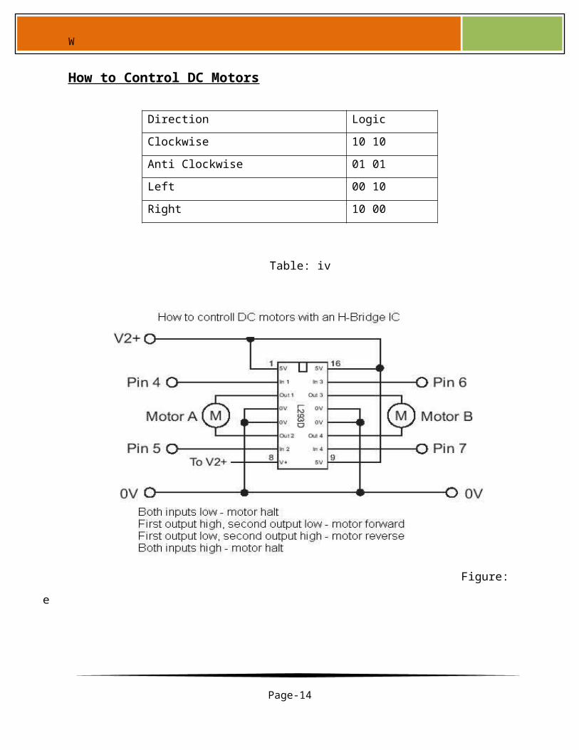
How to Control DC Motors
Page-11

W
Table: iv
Figure: e
Mobile phone is connected to ear phones and the earphones are dissected in the
following way
Page-12
Direction Logic
Clockwise 10 10
Anti Clockwise 01 01
Left 00 10
Right 10 00

W
Figure: f
Positive terminal –Tip
Negative terminal-Ring
Above mentioned terminals are connected as per the circuit.
Page-13
W
Following is the circuit diagram.
Figure: g
Components used in this circuit
Decoder
Microcontroller
H-bridge
Crystal Oscillator
Resistors
Capacitors
Diodes
Power supply
Page-14

W
Software Used
Professional Proteus
Win Avr
Avr studio
Extreme burne
Figure: h
Page-15

W
Figure: i
Page-16

W
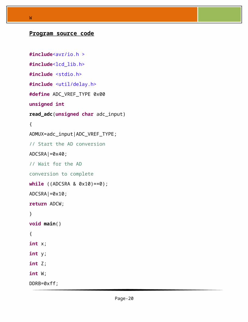
Program source code
#include<avr/io.h >
#include<lcd_lib.h>
#include <stdio.h>
#include <util/delay.h>
#define ADC_VREF_TYPE 0x00
unsigned int
read_adc(unsigned char adc_input)
{
ADMUX=adc_input|ADC_VREF_TYPE;
// Start the AD conversion
ADCSRA|=0x40;
// Wait for the AD
conversion to complete
while ((ADCSRA & 0x10)==0);
ADCSRA|=0x10;
return ADCW;
}
void main()
{
int x;
int y;
int Z;
int W;
DDRB=0xff;
DDRD=0xff;
DDRC=0xff;
char a[15];
char B[15];
Page-17

W
ADMUX=ADC_VREF_TYPE;
ADCSRA=0x85;
LCDinit();
LCDclr( );
while(1)
{
x=read_adc(0);
sprintf(a,"x=%4d",x);
LCDGotoXY(0,0);
LCDstring(a,6);
y=read_adc(2);
sprintf(a,"y=%4d",y);
LCDGotoXY(0,1);
LCDstring(a,6);
Z=read_adc(4);
sprintf(B,"Z= %4d",Z);
LCDGotoXY(8,0);
LCDstring(B,7);
W=read_adc(6);
sprintf(B,"W= %4d",W);
LCDGotoXY(8,1);
LCDstring(B,7);
if(x<350 && y<350 && Z>1000
&& W<350 ) //press 02
{
PORTD=0b10100000;
}
if(x<350 && y>350 && Z<350
&& W<350) //press 04
{
Page-18

W
PORTD=0b01100000;
}
if(x<350 && y>350 &&Z>350 &&
W<350) //press 06
{
PORTD=0b10010000;
}
if(x>350 && y<350 &&Z<350 &&
W<350) //press 08
{
PORTD=0b01010000;
}
if(x<350 && y>350 &&Z<350 &&
W>350) // press 05
{
PORTD=0b00000000;
}
}
}
End
PROJECT OVERVIEW
Page-19
W
Block Diagram: 3
Table: v
In this project the robot, is controlled by a mobile phone that makes call to
the mobile phone attached to the robot in the course of the call, if any button
is pressed control corresponding to the button pressed is heard at the other
end of the call. This tone is called dual tone multi frequency tome (DTMF)
robot receives this DTMF tone with the help of phone stacked in the robot
The received tone is processed by the atmega16 microcontroller with the
help of DTMF decoder MT8870 the decoder decodes the DTMF tone in to its
equivalent binary digit and this binary number is send to the microcontroller,
the microcontroller is preprogrammed to take a decision for any give input
Page-20

W
and outputs its decision to motor drivers in order to drive the motors for
forward or backward motion or a turn.
The mobile that makes a call to the mobile phone stacked in the robot acts
as a remote. So this simple robotic project does not require the construction
of receiver and transmitter units.
DTMF signaling is used for telephone signaling over the line in the voice
frequency band to the call switching center. The version of DTMF used for
telephone dialing is known as touch tone.
DTMF assigns a specific frequency (consisting of two separate tones) to each
key s that it can easily be identified by the electronic circuit. The signal
generated by the DTMF encoder is the direct al-gebric submission, in real
time of the amplitudes of two sine(cosine) waves of different frequencies, i.e.
,pressing 5will send a tone made by adding 1336hz and 770hz to the other
end of the mobile. The tones and assignments in a dtmf system shown below
Circuit Description :
Figure: j
Page-21

W
Block Diagram:4
Figures shows the block diagram and cicuit diagram of the microcontroller-
based robot. The important components of this robot are DTMF decoder,
Microcontroller and motor driver.
An MT8870 series dtmf decoder is used here. All types of the mt8870 series
use digital counting techniques to detect and decode all the sixteen DTMF
tone pairs in to a four bit code output. The built -in dila tone rejection circuit
eliminated the need for pre- filtering. When the input signal given at pin2
(IN-) single ended input configuration is recognized to be effective, the
correct four bit decode signal of the DTMF tone is transferred to Q1 (pin11)
through Q4(pin14) outputs.
The atmega 16 is a low power, 8 bit, cmos microcontroller based on the AVR
enhanced RISC architecture. It provides the following feature: 16kb of in
system programmable flash memory with read write capabilities, 512bytes of
EEPROM, 1KB SRAM, 32 general purpose input/output lines. 32 general
purpose working registers. All the 32 registers are directly connected to the
arithmetic logic unit, allowing two independent registers to be accessed in
one signal instruction executed in one clock cycle. The resulting architecture
Page-22

W
is more code efficient. Outputs from port pins PD0 through PD3 and PD7 of
the microcontroller are fed to inputs IN1 through IN4 and enable pins (EN1
and EN2) of motor driver L293d respectively, to drive geared motors. Switch
S1 is used for manual reset.
the notations are :
ic1 - mt8870
ic2 - atmega16
ic3 - l293d
ic4 - cd7004
r1,r2 - 100k resistances
r3 - 330k resistances
r4-r8 - 10k resistances
c1- 0.47 micro farat capacitor
c2,c3,c5,c6 - 22pfarat capacitor
c4 - 0.1micro farat capacitor
xtal1 - 3.57 mhz crytal
xtal2 - 12mhz crystal
s1 - push to on switch
m1,m2 - 6v 50rpm motor
batt- 6v
Page-23
W
Block Diagram: 5
In order to control the robot, you have to make a call to the cell phone
attached to the robot from any phone.
now the phone is picked by the phone on the robot through auto answer
mode(which is in the phn, just enable it).
now when you press 2 the robot will move forward
when you press 4 the robot will move left
when you press 8 the robot will move backwards
when you press 6 the robot will move right
when you press 5 the robot will stop.
Page-24

W
Construction
Figure: k
for constructing this robot, you require these components
Components used:-
" MT8870 DTMF DECODER - 1
" Atmega 16 microcontroller - 1
" L293d motor driver ic - 1
" Cd7004 not gate ic - 1
" 1n4007 diode - 1
" 100k resistances - 2
" 10 k resistances - 5
Page-25
W
" 330 k resistances - 1
" 0.47mf capacitors - 1
" 0.1mf capacitors - 1
" 22pf capacitors - 4
" 3.57mhz crystal - 1
" 12mhz crystal - 1
" Push to on switch - 1
" 2 geared motors (6v, 50 rpm) - 2 (4 for four wheel drive)
" Battery 6v - 1
wheels - 4
cell phone - 2 (one urs and one can be ur frnds)
hands free - 1 (for the phn on the rover)
you have to place a cell phone on the rover. The cell phone is connected to
the rover through hands free. Construct the rover in the shape which is given
below.
You can get these parts from any electronic store with ease
Page-26

W
To connect the hands free with the circuit
Figure :l
there are always two connections which come out of the phone,
these connections are
1. Tip
2. Ring
i'll prefer to use hands free which have a straight jack (similar to the ones
which we use in our iPods, but a thinner one)
the tip of that jack is called the "tip"
and the rest part behind the tip after a black strip is the ring So connect
these two connections with the circuit and you will be done
Page-27

W
Mobile Controlled Robot Using DTMF Technology
Project Report
In recent days mobile controlled robot using DTMF technology are playing
vital role in industrial automation and hazardous work conditions. Automated
robots have several advantages in terms of accuracy and reliability, in our
“project Mobile Controlled Robot using DTMF i.e. Dual Tone Multi Frequency
tone, Technology”; we implemented a cell phone operated robot using DTMF
technology, these systems are applicable in defense like bomb detector, spy
robot and also in surveillance, in this DTMF based robot project we discuss
about the design and implementation of the automated robot.
Page-28

W
Advantages
Used to control house hold appliances
In industries and factories for remote sensing
Using 3g technology we can spy a place
Long distance remote sensing
Can be implemented in avionics to switch auto pilot from ground station by
sending a particular frequency
Disadvantages
Not at all useful if we do not have network
Call charges
Head phones which would be damaged very frequently
Page-29

W
Proposed mobile phone controlled robot
The DTMF robot we use a mobile phone to control the operations of the
robot, the robot has a mobile phone internally so when we make calls to that
mobile the corresponding tone is here’d at the other end. Using DTMF code
the direction and motion of the robot is controlled. Presently the robot
system can sense the smoke and gas emission and can intimate to the
operators with the help of alarm.
Technical specifications
The key aspect in this mobile phone controlled robot is the monitoring action
performed by the micro controller. The ATMEGA-16 micro controller used in
this project is low power and high performance CMOS 8- bit 4k byte EPROM
which is ideal for low power consumption applications. The pin configuration
and features of the micro controller are explained in later sections.
Page-30

W
Conclusion & Future Scope
So far the present system is designed mainly for the supervision applications. In
the area of suspectance, the robot can be directed and if any smoke or gas is
identified the robot can produce alarm and also informs the operator. The
comments from the operator can also be transmitted to the area where the robot
moves. Further the key board can be interfaced with the TV connected at
receiver side to increase the number of comments given to the robot. Amplifier is
needed to be connected to the speaker of the mobile interfaced with the robot to
pass the comments directly through mobile from the remote mobile. The above
system can also used for military purpose as bomb detection and as spy robot.
Page-31


