
2-PHASE STEPPING SYSTEMS
Ver.2

1
Compliance with international standardsThe standard specification SANMOTION F series stepping driver complies with UL and EN safety standards.Stepping motors complying with UL and EN standards are available upon request.
F series DRIVERH series MOTORSH series MOTOR
F series DRIVER features
Low-vibration mode1
0
200
400
600
800
1000
1200
1400
1600
0 100 200 300 400 500 600 700 800 900 1000
pulse/s
Low-Vibration Mode ON
Driver : US1D200P10Motor : 103H7123-0410Source voltage : DC24VWire current : 2.0A/phaseDivision : 2TG : 11TG(7V/1000rpm)
0
200
400
600
800
1000
1200
1400
1600
0 100 200 300 400 500 600 700 800 900 1000
pulse/s
Low-Vibration Mode OFF
Sp
eed
var
iati
on(
%)
Sp
eed
var
iati
on(
%)
Driver : US1D200P10Motor : 103H7123-0410Source voltage : DC24VWire current : 2.0A/phaseDivision : 2TG : 11TG(7V/1000rpm)
DC input
DC input
Compact / Light weight2
0 10050 150 200 250
2-phase bipolarF series
2-phase bipolarCurrent model
2-phase unipolarF series
2-phase unipolarCurrent model
MASS(g)
Light weight
0 50 100 150 200 250 300 350
2-phase bipolarF series
2-phase bipolarCurrent model
2-phase unipolarF series
2-phase unipolarCurrent model
Volume(cm3)
Compact
DC input
2-phase STEPPING SYSTEMS

2
Dim
en
sio
ns
Ste
pp
ing
Mo
tors
wit
h I
nte
rna
l d
riv
ers
S
tep
pin
g m
oto
rS
et
mo
de
lIC
fo
r ste
pp
ing
mo
tor
Set model
DC input
Bipolar standard (standard model)The standard set includes a F series driver and a H or SH series motor.
Stepping motors with integrated drivers
A driver incorporating a motion control function needed for
driving a motor and a 2-phase stepping motor were integrated into a single unit.
Unipolar standard (standard model)The standard set includes a F series driver and a H or SH series motor.
P.4
P.13
P.14
Motor flange size
42 50 56 60
(□1.65inch)(□1.10inch) (□1.97inch)(□2.20inch)(□2.36inch)
28
42
Motor flange size
(□1.65inch)(□2.36inch)
60
42 56
Motor flange size
28
(□1.65inch)(□1.10inch) (□2.20inch)

3
How do you want to control the equipment?The F series offers the choice of 3 different control methods
Control method
Program command
control using PLC I/O
Control using a pulse generator
Network control
using serial communication(RS-485)
DC inputbipolar standard
Motion is generated by pulse input commands from an upper-level controller.
System configuration diagram P14Set part number nomenclature P16Motor specifications P27 to 48General specifications P49・50Motor dimension drawing P51 to 54Driver dimension drawing P55
DC inputstepping motors with integrated drivers
Startup via I/O :
Initiate program containing speed,
acceleration/deceleration, and travel
distance commands stored in the driver via
the I/O.
Startup via serial communication :
Control by sending data for speed, acceleration/deceleration, and travel distance commands via serial communication.
System configuration diagram P4Specifications P6Dimensions P5 to 6
DC inputunipolar standard
Drive Specification
Control using a pulse generator
Motion is generated by pulse input commands from an upper-level controller.
System configuration diagram P13Set part number nomenclature P16Motor specifications P27 to 48General specifications P49・50Motor dimension drawing P51 to 54Driver dimension drawing P55
F series DRIVERH series MOTORSH series MOTOR2-phase STEPPING SYSTEMS

4
Dim
en
sio
ns
Ste
pp
ing
Mo
tors
wit
h I
nte
rna
l d
riv
ers
S
tep
pin
g m
oto
rS
et
mo
de
lIC
fo
r ste
pp
ing
mo
tor
Single phase
AC100 Vto
AC230 V
(t)
(r)
DC24 V
Bundled cable for
input/output signal(300 mm)
Bundled cable for
DC power(350 mm)
Noise filter
Filters out incoming noise from power line
Molded case
circuit breaker
Protects the power line. Cuts off circuit in the event of overcurrent.
Electromagnetic
contactor
Switches driver power on/off.Use together with a surge protector.
Switching power
supply
Converts AC power to DC power
Setup software : SFPAIW-01
Stepping Motors with Integrated drivers
DC input System configuration
Host Devices
PLC and controllers are available as the host device.
PLC

5
Stepping motor
2-phase STEPPING SYSTEMS
Specifications
Stepping motors with integrated drivers
Features
1.Driver and motor are now integrated into a single unit.
A driver incorporating a motion control function needed for driving a motor and a 2-phase stepping motor were integrated into a single unit for enabling a more compact installation space and less wiring.
2.Three types of operation modes can be selected to match
the specific application.
(1)Control by command pulses
(2)Program control by general-purpose I/O(Parallel)
(3)Compliant with RS-485, half-duplex asynchronous
communication
DB21M142S-01E=DC24VI=Rated currentJL=0.94×10⁻⁴kg・m2
0.1
0.6
0.5
0.4
0.3
0.2
0
To
rqu
e (N
-m)
0.1 1 10 100
DB22M162S-01E=DC24VI=Rated currentJL=2.6×10⁻⁴kg・m2
Pulse rate(kpulse/s)Pulse rate(kpulse/s)0.1 1 10 100
0.2
0.4
0.6
0.8
1.0
1.2
1.4
1.6
0
To
rqu
e(o
z·in
.)
70
80
0
60
50
40
30
20
10
To
rqu
e (k
gf-
cm)
To
rqu
e (N
-m)
To
rqu
e(o
z·in
.)
To
rqu
e (k
gf-
cm)
1
2
3
4
5
6
0
140
160
180
200
220
0
120
100
80
60
40
202
4
6
8
10
12
14
16
0
Number of rotations(min-1) Number of rotations(min-1)2000 3000 5000100 1000 2000 3000 5000100 1000
Pulse rate-torque characteristics
Dimensions[Unit : mm(inch)]
1O
42 3
N
5 6
E
9
A F
8
34
7
6 5
2
10
DCB
CN1:POWER
1・・・・19
2・・・・20
12
CN2:I/O
RSWPSW DSW
4.5
42±
0.5(
1.65±
.02)
31±0.25(1.22±.01)
42± 0.5(1.65±.02)
31±
0.25(
1.22±
.01)
R3MIN.
70+20
1.5± 0.76(.59±.03)
24±0.5(.94±.02)
φ5
0 -0.0
13
0.05
0.025
(EFFECTIVELENGTH)
Manufacturer:JST
CONNECTOR:S02B-PASK-2
CONNECTOR:SM20B-SHLDS-GW-TF
Manufacturer:JST± 0.15(1.18±.01)
NA
ME
TAP DEPTH 4(.16)MIN.
4-M3×0.5
PL
ATE
A
A
EARTH TERMINAL
M2.5X0.45X4L
Use proper
techniques.grounding
15
( )
()
2.76+.08
.00
( )59+.04
.00
φ.1
968-
+.00
00.0
005
φ22
0 -0.0
5()
φ.8
7-+.
000
.002
DC input
□42mm(□1.65inch) □60mm(□2.36inch)
□42mm(□1.65inch)
The date are measured under the drive condition of our company. The drive torque may very depending on the accuracy of customer-side equipment.

6
Dim
en
sio
ns
Ste
pp
ing
Mo
tors
wit
h I
nte
rna
l d
riv
ers
S
tep
pin
g m
oto
rS
et
mo
de
lIC
fo
r ste
pp
ing
mo
tor
Specifications
Basic specifications
Part number(Flange size) DB21M142S-01(□42) DB22M162S-01(□60)
Input source(Note1) DC24 V ±10 %
Getaway torque(A) 2 MAX. 3 MAX.
Environment
Protection class Class I
Operation environment Installation category(over-voltage category) : II, pollution degree : 2
Applied standards EN61010-1
Operating ambient temperature(Note2)
0 to +40℃
Conservation temperature -20 to +60℃
Operating ambient humidity 35 to 85%RH(no condensation)
Conservation humidity 10 to 90%RH(no condensation)
Operation altitude 1000 m(3280 feet)MAX. above sea level
Vibration resistanceTested under the following conditions ; 4.9m/s2, frequency range 10 to 55Hz, direction along X, Y and Z axes, for 2 hours each
Impact resistance Not influenced at NDS-C-0110 standard section 3.2.2 division “C” .
Withstand voltageNot influenced when 1500V AC is applied between power input terminal and cabinet for one minute.
Insulation resistance 10M ohm MIN. when measured with 500V DC megohmmeter between input terminal and cabinet.
Mass(Weight) 0.5kg(1.10lbs) 0.87kg(1.92lbs)
FunctionProtection function Against driver overheat
LED indicator Alarm monitor
I/O signals
Command pulse input signal(Note3)Photo coupler input method, input resistance 220ΩInput signal voltage : “H” = 4.0 to 5.5V, “L” = 0 to 0.5V
Power down input signal(PD)Photo coupler input method, input resistance 470ΩInput signal voltage : “H” = 4.0 to 5.5V, “L” = 0 to 0.5V
Step angle setting selection input(EXT)Photo coupler input method, input resistance 470ΩInput signal voltage : “H” = 4.0 to 5.5V, “L” = 0 to 0.5V
FULL/HALF setting selection input(F/H)Photo coupler input method, input resistance 470ΩInput signal voltage : “H” = 4.0 to 5.5V, “L” = 0 to 0.5V
EMG input signal Photo coupler input method, input resistance 470ΩInput signal voltage : “H” = 4.0 to 5.5V, “L” = 0 to 0.5V
BUSY output signal Open collector output by photo couplerOutput signal standard : Vceo = 30V MAX., Ic = 20mA MAX.
Phase origin monitor output signal(MON)Open collector output by photo couplerOutput signal standard : Vceo = 30V MAX., Ic = 20mA MAX.
Alarm output signal(AL)Open collector output by photo couplerOutput signal standard : Vceo = 30V MAX., Ic = 20mA MAX.
(Note1)Note that the power voltage must not exceed 24VDC + 10% (26.4VDC).(Note2)If the driver is placed in a box, the temperature inside the box must not exceed this specified range.(Note3)The maximum input frequency is 250k pulse/s.
6
7
A98
B CDE
01
2
5 4 3
F NO
321 654
1
R4MIN.
4-φ4.5 0+0.5
4-φ.18 .00+.02
(EFFECTIVELENGTH)
CONNECTOR:S02B-PASK-2Manufacturer:JSTCN1:POWER
2
2・・・・20
1・・・・19
Manufacturer:JSTCONNECTOR:SM20B-SHLDS-GW-TF
CN2:I/O
RSWPS DS EARTH TERMINALM2.5X0.45X4L
NA
ME
A
0.075 A
A0.1
0.025
PL
ATE
Use proper
techniques.grounding
88 +20
7±0.25(.27±.01)
φ3
8.1±
0.25(φ
1.5±
.01)
20.6±0.5(.81±.02)60±0.5(2.36±.02)
5.8±0.15(.23±.01)
47.1±0.13(1.85±.01)
60±
0.5(
2.36±
.02)
47.1±
0.13(
1.8
5±.0
1)
1.5±0.25(.06±.01)
φ6.
350 -0
.013φ
.25
+.00
0-.0
01(
)
( )3.46+.08
.00
15+10( ).59
+.04.00
( )
□60mm(□1.65inch)
7
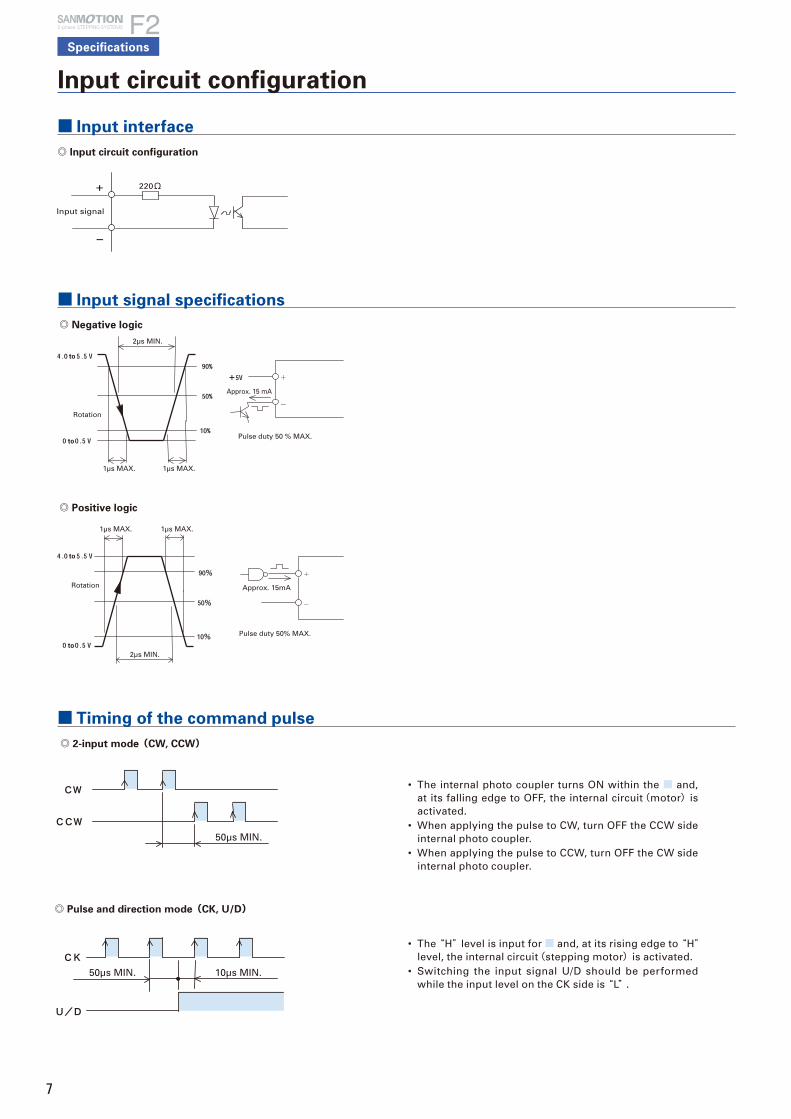
◎ 2-input mode(CW, CCW)
■ Timing of the command pulse
Input circuit configuration
■ Input interface
◎ Input circuit configuration
■ Input signal specifications
• The internal photo coupler turns ON within the ■ and, at its falling edge to OFF, the internal circuit(motor)is activated.
• When applying the pulse to CW, turn OFF the CCW side internal photo coupler.
• When applying the pulse to CCW, turn OFF the CW side internal photo coupler.
• The “H” level is input for ■ and, at its rising edge to “H”level, the internal circuit(stepping motor)is activated.
• Switching the input signal U/D should be performed while the input level on the CK side is “L” .
Specifications
2-phase STEPPING SYSTEMS
Input signal
220Ω
Rotation
to
to
to
to
Rotation
2μs MIN.
2μs MIN.
1μs MAX. 1μs MAX.
Approx. 15 mA
Pulse duty 50 % MAX.
Approx. 15mA
Pulse duty 50% MAX.
1μs MAX. 1μs MAX.
50μs MIN.
50μs MIN. 10μs MIN.
◎ Pulse and direction mode(CK, U/D)
◎ Negative logic
◎ Positive logic

8
Dim
en
sio
ns
Ste
pp
ing
Mo
tors
wit
h I
nte
rna
l d
riv
ers
S
tep
pin
g m
oto
rS
et
mo
de
lIC
fo
r ste
pp
ing
mo
tor
■ Input circuit configuration
• Shaded area indicates internal photo coupler “ON” .
• EXT input signalEXT photo coupler “ON” enables a function by external F/H input signal.EXT photo coupler “OFF” enables the setting of a number of micro steps by main unit’s rotary switch S.S.
• F/H input signalF/H photo coupler “ON” sets HALF step (2-division) operation.F/H photo coupler “OFF” sets FULL step (1-division) operation.
• Refer to switching EXT and F/H input signal in the [FULL/HALF input signal, command pulse, and step angle select].
• When switching the step angle by EXT and F/H input signal, the phase origin LCD may not turn ON and the phase origin monitor output may not output when stop.
Refer to the MON output in the [Output Interface].
■ Output circuit configuration(BUSY、MON、AL)
Output interface
■ Mon output
• When the motor excitation phase is at the phase origin (power ON status), the photo coupler is turned “ON” , and the upper D.P of status LED turns on synchronously.
• Output from MON is set to on at every 7.2 degrees of motor output shaft from phase origin.
Approx. 10mA
Input signal
Command pulse
100μs MIN. 10μs MIN.
◎ Input circuit configuration(PD、EXT、F/H、EMG)
◎ Timing of command pulse, step angle selection, and
FULL/HALF selection input signal
Output signal
MAX. 20mA
MAX. 30V
Driver
CW pulse
CCW pulse
Mon output
Phase origin position Phase origin position
Motor shaft
Switching to FULL step by external F/H
FULL stepHALF stepStop position at
FULL step
◎ When changing the division setting by F/H input signal.
• When changing the motor division setting by the external input signal and the rotary switch as shown in the example below, the motor cannot stop where MON output signal can be output. Take this into consideration when using the MON output signal.

9
WIRING
Specification
2-phase STEPPING SYSTEMS
Signal ReferenceDesignation
PinNumber Function Summary
General-purposeinput common
+COM 6 Input signal common of the 6 to 9 pinsDC 5V is input.
Alarm clear signal(standard)
ALMC 6 Recoverable alarms are cleared.Internal photo coupler off→ on…Alarm clear
General-purposeinput 1
IN1 6
This is a general-purpose input signal that can beused by program driving.Internal photo coupler on…General purpose input 1 onInternal photo coupler off … General purpose input 1 off
Emergency stopinput
EMG 6The emergency stop signal is input.Internal photo coupler on…No emergency stopInternal photo coupler of…Emergency stop
Origin signal ORG 6
The origin signal used for the return to originoperation is input.Internal photo coupler on…Origin signal onInternal photo coupler off…Origin signal off
+ directionovertravel signal
+OT 7
An overtravel signal in the + direction is input.Internal photo coupler on …+ direction overtravel not arrivedInternal photo coupler off …+ direction overtravelarrived
General-purposeinput 2
IN2 7
This is a general-purpose input signal that can beused by program driving.Internal photo coupler on…General purpose input 2 onInternal photo coupler off …General purpose input 2 off
Emergency stopinput
EMG 7The emergency stop signal is input.Internal photo coupler on…No emergency stopInternal photo coupler off…Emergency stop
Origin signal ORG 7
The origin signal used for the return to originoperation is input.Internal photo coupler on…Origin signal onInternal photo coupler off … Origin signal off
Alarm clear signal ALMC 7 Recoverable alarms are cleared.Internal photo coupler off→ on…Alarm clear
- directionovertravel signal
- OT 8
An overtravel signal in the - direction is input.Internal photo coupler on …- direction overtravel not arrivedInternal photo coupler off…- direction overtravelarrived
General-purposeinput 3
IN3 8
This is a general-purpose input signal that can beused by program driving.Internal photo coupler on…General purpose input 3 onInternal photo coupler off … General purpose input 3 off
Emergency stopinput
EMG 8emergency stop signal is input.Internal photo coupler on…No emergency stopInternal photo coupler off…Emergency stop
Origin signal ORG 8
The origin signal used for the return to originoperation is input.Internal photo coupler on…Origin signal onInternal photo coupler off … Origin signal off
Alarm clear signal ALMC 8 Recoverable alarms are cleared.Internal photo coupler off→ on…Alarm clear
Signal ReferenceDesignation
PinNumber Function Summary
Emergency stopsignal
EMG 9The emergency stop signal is input.Internal photo coupler on…No emergency stopInternal photo coupler off…Emergency stop
General-purposeinput 4c
IN4 9
This is a general-purpose input signal that can beused by program driving.Internal photo coupler on…General purpose input 4 onInternal photo coupler off … General purpose input 4 off
Origin signal ORG 9
The origin signal used for the return to originoperation is input.Internal photo coupler on…Origin signal onInternal photo coupler off … Origin signal off
Alarm clear signal ALMC 9 alarms are cleared.Internal photo coupler off→ on…Alarm clear
During motoroperation
BUSY 10The operation status of the motor is output.Internal photo coupler on…During motor operationInternal photo coupler off…During motor stop
During programexecution
PEND 10
The execution status of the program is output.Internal photo coupler on…During program executionInternal photo coupler off…Program executioncomplete
Zone signal ZONE 10 on when the current position is inside thecoordinates that were set beforehand.
During programexecution
PEND 11
The execution status of the program is output.Internal photo coupler on…During program executionInternal photo coupler off…Program executioncomplete
During motoroperation
BUSY 11The operation status of the motor is output.Internal photo coupler on…During motor operationInternal photo coupler off…During motor stop
Zone signal ZONE 11 Turns on when the current position is inside thecoordinates that were set beforehand.
Alarm output ALM 12
When various alarm circuits operate in the driver, an external signal is output.At this time, the stepping motor becomes non excited status.
Output signalcommon
OUT_COM 13 It is for the output signal common.
DATA+ DATA+ 14 It is for the serial signal.
DATA- DATA- 15 It is for the serial signal.
■ Specification Summary of Input/Output Signals (Serial I/F mode)
■ Specification Summary of Input/Output Signals (Pulse train I/F mode)
Signal ReferenceDesignation
PinNumber Function Summary
CW pulse input(Standard)
CW+CW-
12
When “2 input mode” ,Input drive pulse rotating CW direction.
Pulse train input CK+CK-
12
When “1 input mode” ,Input drive pulse train for motor rotation.
CCW pulse input(Standard)
CCW+CCW-
34
When “2 input mode” ,Input drive pulse rotating CCW direction.
Rotational direction input
U/D+U/D-
34
When “1 input mode” ,Input motor rotational direction signal.Internal photo coupler ON … CW directionInternal photo coupler OFF … CCW direction
General-purposeinput common
+COM 6 Input signal common of the 6 to 9 pinsDC5V is input.
Power down input
PD 6
Inputting PD signal will cut off (power off) the current flowing to the Motor (With dip switch select, change to the Power low function is possible).PD input signal on (internal photo coupler on)… PD function is valid.PD input signal off (internal photo coupler off)… PD function is invalid.
Step angle select input
EXT 7
FULL/HALF select input will become valid by inputting EXT signal.EXT input signal on (internal photo coupler on)… External input signal F/H is validEXT input signal off (internal photo coupler off)… Main body rotary switch S.S is valid
Signal ReferenceDesignation
PinNumber Function Summary
FULL/HALFselect input
F/H 8
When EXT input signal on (internal photo coupler on),F/H input signal on (internal photo coupler on)… HALF stepF/H input signal off (internal photo coupler off)… FULL step
Emergency stop
EMG 9The emergency stop signal is input.Internal photo coupler on…No emergency stopInternal photo coupler off…Emergency stop
During motoroperation
BUSY 10
The operation status of the motor is output.Internal photo coupler on…During motor operationInternal photo coupler off…During motor stop
Phase originmonitor output
MON 11
When the excitation phase is at the origin (in power on) it turns on.When FULL step, ON once for 4 pulses, when HALF step, ON once for 8 pulses.
Alarm output ALM 12When alarm circuits actuated inside the Driver, outputs signals to outside. Then the Stepping motor becomes unexcited status.
Output signalcommon
OUT_COM 13 It is for the output signal common.
* As for the Motor rotational direction, CW direction is regard as the clockwise revolution by viewing the Motor from output shaft side.

10
Dim
en
sio
ns
Ste
pp
ing
Mo
tors
wit
h I
nte
rna
l d
riv
ers
S
tep
pin
g m
oto
rIC
fo
r ste
pp
ing
mo
tor
Se
t m
od
el
Signal ReferenceDesignation
PinNumber Function Summary
Program drive Start/Stop
START+ START-
12
Commands the start and stop of program driving.Internal photo coupler on…Program driving start Internal photo coupler off…Program driving stop
Program pause PAUSE+ PAUSE-
34
When START signal on, a pause in program driving is commanded. Internal photo coupler on…Program driving pause Internal photo coupler off…Program driving pause release
General-purpose input common
+COM 6 Input signal common of the 6 to 9 pins DC5V is input.
Alarm clear signal (standard)
ALMC 6 Recoverable alarms are cleared. Internal photo coupler off → on…Alarm clear
General-purpose input 1
IN1 6
This is a general-purpose input signal that can be used by program driving. Internal photo coupler on…General purpose input 1 on Internal photo coupler off … General purpose input 1 off
Program number selection bit 1
B1 6
The program number is selected along with other bits. (Subordinate bit) Internal photo coupler on…Corresponding bit 1 Internal photo coupler off… Corresponding bit 0
Emergency stop input
EMG 6The emergency stop signal is input. Internal photo coupler on…No emergency stop Internal photo coupler off…Emergency stop
Origin signal ORG 6
The origin signal used for the return to origin operation is input. Internal photo coupler on…Origin signal on Internal photo coupler off … Origin signal off
+ direction overtravel signal
+OT 7
An overtravel signal in the + direction is input. Internal photo coupler on …+ direction overtravel not arrived Internal photo coupler off …+ direction overtravel arrived
General-purpose input 2
IN2 7
This is a general-purpose input signal that can be used by program driving. Internal photo coupler on…General purpose input 2 on Internal photo coupler off … General purpose input 2 off
Program number selection bit 2
B2 7
The program number is selected along with other bits. (The second bit from the subordinate) Internal photo coupler on…Corresponding bit 1 Internal photo coupler off… Corresponding bit 0
Emergency stop input
EMG 7 The emergency stop signal is input. Internal photo coupler on…No emergency stop Internal photo coupler off…Emergency stop
Origin signal ORG 7
The origin signal used for the return to origin operation is input. Internal photo coupler on…Origin signal on Internal photo coupler off … Origin signal off
Alarm clear signal
ALMC 7 Recoverable alarms are cleared. Internal photo coupler off → on…Alarm clear
- direction overtravel signal
-OT 8
An overtravel signal in the - direction is input. Internal photo coupler on …- direction overtravel not arrived Internal photo coupler off …- direction overtravel arrived
General-purpose input 3
IN3 8
This is a general-purpose input signal that can be used by program driving. Internal photo coupler on…General purpose input 3 on Internal photo coupler off … General purpose input 3 off
Program number selection bit 4
B4 8
The program number is selected along with other bits. (The third bit from the subordinate) Internal photo coupler on…Corresponding bit 1 Internal photo coupler off… Corresponding bit 0
Emergency stop input
EMG 8The emergency stop signal is input. Internal photo coupler on…No emergency stop Internal photo coupler off…Emergency stop
Origin signal ORG 8
The origin signal used for the return to origin operation is input. Internal photo coupler on…Origin signal on Internal photo coupler off … Origin signal off
Alarm clear signal
ALMC 8 Recoverable alarms are cleared. Internal photo coupler off → on…Alarm clear
Signal ReferenceDesignation
PinNumber Function Summary
Emergency stop signal
EMG 9 The emergency stop signal is input. Internal photo coupler on…No emergency stop Internal photo coupler off…Emergency stop
General-purpose input 4
IN4 9
This is a general-purpose input signal that can be used by program driving. Internal photo coupler on…General purpose input 4 on Internal photo coupler off … General purpose input 4 off
Program number selection bit 8
B8 9
The program number is selected along with other bits. (The fourth bit from the subordinate) Internal photo coupler on … Corresponding bit 1 Internal photo coupler off … Corresponding bit 0
Origin signal ORG 9
The origin signal used for the return to origin operation is input. Internal photo coupler on…Origin signal on Internal photo coupler off … Origin signal off
Alarm clear signal
ALMC 9 Recoverable alarms are cleared. Internal photo coupler off → on…Alarm clear
During motor operation
BUSY 10The operation status of the motor is output. Internal photo coupler on…During motor operation Internal photo coupler off…During motor stop
During program execution
PEND 10
The execution status of the program is output. Internal photo coupler on…During program execution Internal photo coupler off…Program execution complete
Zone signal ZONE 10 Turns on when the current position is inside the coordinates that were set beforehand.
During program execution
PEND 11
The execution status of the program is output. Internal photo coupler on…During program execution Internal photo coupler off…Program execution complete
During motor operation
BUSY 11The operation status of the motor is output. Internal photo coupler on…During motor operation Internal photo coupler off…During motor stop
Zone signal ZONE 11 Turns on when the current position is inside thecoordinates that were set beforehand.
Alarm output ALM 12
When various alarm circuits operate in the driver, an external signal is output. At this time, the stepping motor becomes non excited status.
Output signal common
OUT_COM 13 It is for the output signal common.
DATA+ DATA+ 14 It is for the serial signal.
DATA- DATA- 15 It is for the serial signal.
■ External Wiring Diagrams
DC+24V
24G
+24V
24G
5G+5V
RXD
TXD
DE
1
2
1
23
4
5
6
7
8
9
10
11
12
13
CN1
14
15
20
CN2
Driver
30V 20mA MAX.
2 Phase Stepping Motor
PowerSupply
Controller
DATA+
DATA-
GND(-5G)
CW+/START+
CW-/START-CCW+/PAUSE+
CCW-/PAUSE-
+COM
PD/IN1/B1
EXT/IN2/B2
FH/IN3/B4
IN4/B8
BUSY/OUT1
MON/OUT2
ALM
OUT_COM
■ Specification Summary of Input/Output Signals (Parallel I/F mode)

11
SET UP
■ Function Select Dip Switch
◎ For pulse stream I/F mode
Input mode select(F/R)
Input pulse mode selectionThis switch setting is only effective in pulse stream I/F mode.F / R Input pulse modeON 1 input mode(CK,U/D)
OFF 2 input mode(CW,CCW)
Low vibration mode select(LV)
Low vibration and smooth operation is enabled even by the rough resolution setting(e.g. 1 division, 2 division).This switch setting is only effective in pulse stream I/F mode.For parallel I/F mode and serial I/F mode, this is usually a low vibration operation.
LV Operation
ON Low vibration operation
OFF Micro step operation
* When LV select is ON (low vibration mode), operational process of driving pulse will be carried out inside the Driver. Therefore, the Motor movement delays for the time of 3.2ms pulse per input pulse. Note that depending upon the combined Motor, load,driving profile and etc, it may take a while until the shaft is adjusted when the Motor stops. (In parallel I/F mode and serial I/F mode there is no delay)
Power down select(PD)Select the Motor winding current value when inputting the power down signal.This switch setting is only effective in pulse stream I/F mode.
PD Motor winding current
ON Current value by rotary switch STP(Power Low)
OFF 0A(Power OFF)
* PD function (the setting selected by PD of the function select dip switch) is enabled by PD input signal ON (built-in photo coupler ON) of Input/Output signal connector (CN2). Power down signal input is prior to all the other current settings except for alarms. The operational status may not be maintained such as power swing due to output torque drop or lower operation due to Motor current OFF (unexcited Motor). Pay extra attention to the input timing of the power down signal in addition that the security device should be installed to the machine.
Excitation select(EORG)
* By turning on the EORG, excitation phase when power OFF is saved.
, Operation mode selection (I.SEL, S.SEL)
The operation mode is selected.I.SEL S.SEL Operation mode
OFF - Pulse stream I/F mode
ONOFF Parallel I/F mode
ON Serial I/F mode* Change the operation mode selection switch after cutting off the driver’ s power supply.
◎ For parallel I/F mode or serial I/F mode
The communication speed of serial communication is set.
Switch Set valueCommunication speed(bps)
9,600 19,200 38,400
F/ROFF ○ ○ ○
ON
LVOFF ○ ○
ON ○
PDOFF ○ ○
ON ○
* The setting change after the power supply is turned on is invalid. It does not function as a F/R, LV, and PD.
* The communication speed of pulse stream I/F mode is fixed at 9600bps.
Specification
2-phase STEPPING SYSTEMS
The functions according to the specification can be selected with this Dip switch.Confirm the ex-factory setting as follows.
F/R
LV
PD
EORG
I. SEL
S. SEL
OFF 2 input mode (CW/CCW pulse)
OFF Micro step operation
OFF Power OFF
OFF Phase origin excitation
OFF
OFF Pulse stream I/F mode
OFF ON
1
2
3
4
5
6
1
2
3
4
5 6
12
Dim
en
sio
ns
Ste
pp
ing
Mo
tors
wit
h I
nte
rna
l d
riv
ers
S
tep
pin
g m
oto
rS
et
mo
de
lIC
fo
r ste
pp
ing
mo
tor
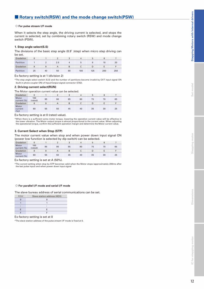
■ Rotary switch(RSW) and the mode change switch(PSW)
When it selects the step angle, the driving current is selected, and stops the current is selected, set by combining rotary switch (RSW) and mode change switch (PSW).
1. Step angle select(S.S)
The divisions of the basic step angle (0.9°/step) when micro step driving can be set.Gradation 0 1 2 3 4 5 6 7
Partition 1 2 2.5 4 5 8 10 20
Gradation 8 9 A B C D E F
Partition 25 40 50 80 100 125 200 250
Ex-factory setting is at 1 (division 2)* The step angle select switch (S.S) and the number of partitions become invalid by EXT input signal ON (built-in photo coupler ON) of Input/Output signal connector (CN2).
2. Driving current select(RUN)
The Motor operation current value can be selected.Gradation 0 1 2 3 4 5 6 7Motorcurrent (%)
100(rated) 95 90 85 80 75 70 65
Gradation 8 9 A B C D E FMotorcurrent (%))
60 55 50 45 40 35 30 25
Ex-factory setting is at 0 (rated value).* When there is a sufficient extra motor torque, lowering the operation current value will be effective in
the lower vibration. The Motor output torque is almost proportional to the current value. When adjusting the operational torque, confirm the sufficient operation margin and determine the Motor current value.
3. Current Select when Stop (STP)
The motor current value when stop and when power down input signal ON (power low function is selected by dip switch) can be selected.Gradation 0 1 2 3 4 5 6 7Motorcurrent (%)
100(rated) 95 90 85 80 75 70 65
Gradation 8 9 A B C D E FMotorcurrent (%) 60 55 50 45 40 35 30 25
Ex-factory setting is set at A (50%).* The current setting when stop by STP becomes valid when the Motor stops (approximately 200ms after the last pulse input) and when power down input signal
◎ For pulse stream I/F mode
◎ For parallel I/F mode and serial I/F mode
The slave bureau address of serial communications can be set.RSW Slave station address (HEX)
0 0
1 1
: :
E E
F F
Ex-factory setting is set at 0* The slave station address of the pulse stream I/F mode is fixed at 0.

(t)
(r)
DC24V/36V
Motor cable●A
Motor
connector
I/O signal connector
I/O signal cable
DC power
connector
DC power cable
Standard model : H series motor, SH series motor,
□28mm(□1.10inch) /□42mm(□1.65inch) /□56mm(□2.20inch)
Single phase
AC100Vto
AC230V
Noise filter
Filters out incoming noise from power line
Molded case
circuit breaker
Protects the power line. Cuts off circuit in the event of overcurrent.
Electromagnetic
contactor
Switches driver power on/off.Use together with a surge protector.
Switching power
supply
Converts AC power to DC power
●A Motor cable□42mm(□1.65inch)
■ Bundled cable(□42mm motors only)
Lead wire UL1430 AWG26Housing HER-6 BLACK(J.S.T Mfg.Co.,Ltd)Pin SEH-001T-P0.6(J.S.T Mfg.Co.,Ltd)
500(1.64 feet) MIN.
2
JST
34
566
5
3
4
2
1
Pin No.
Black
Red
Blue
Yellow
Orange
White
Lead wire color
Host Devices
PLC and controllers are available as the host device.
PLC
13
System configurationDC input
2-phase STEPPING SYSTEMS
Unipolar standard

■ Bundled cable(□42mm motors only)
6
5
3
4
2
1
Pin No.
-
-
Lead wire color
2
JST
34
56
500(1.64 feet) MIN.
Red
Blue
Yellow
Orange
2
1
3
4
Pin No.
Blue
Orange
Red
Yellow
Lead wire color
500(1.64 feet) MIN.
□60mm(□2.36inch)
(t)
(r)
DC24V/36V
Single phase
AC100Vto
AC230V
DC power cable
DC power
connector
Standard model : H series motor, SH series motor,
□28mm(□1.10inch) /□42mm(□1.65inch) /□50mm(□1.97inch)/□56mm(□2.20inch)/□60mm(□2.36inch)
Motor cable●A
Motor
connector
I/O signal connector
I/O signal cable
Noise filter
Filters out incoming noise from power line
Molded case
circuit breaker
Protects the power line. Cuts off circuit in the event of overcurrent.
Electromagnetic
contactor
Switches driver power on/off.Use together with a surge protector.
Switching power
supply
Converts AC power to DC power
Lead wire UL1430 AWG26Housing HER-6 BLACK(J.S.T Mfg.Co.,Ltd)Pin SEH-001T-P0.6(J.S.T Mfg.Co.,Ltd)
Lead wire UL1430 AWG22Housing VER-4N(J.S.T Mfg.Co.,Ltd)Pin SVH-21T-P1.1(J.S.T Mfg.Co.,Ltd)
●A Motor cable□42mm(□1.65inch)
Host Devices
PLC and controllers are available as the host device.
PLC
14
Dim
en
sio
ns
Ste
pp
ing
mo
tor
IC f
or
ste
pp
ing
mo
tor
Bipolar standard
DC input System configuration
Se
t m
od
el
Ste
pp
ing
Mo
tors
wit
h I
nte
rna
l d
riv
ers
2-phase STEPPING SYSTEMS

15
The following set part number specifies a system with an F series unipolar driver (type code : US1D200P10) and a single shaft H series motor (type code : 103H7121-0440),
□56 mm(□
2.20 inch) square flange, and
41.8 mm(1.65 inch) motor length.
DC input
2-phase STEPPING SYSTEMS
Part numbering convention
D H 71 1 SU 61
Power specification
D : DC
Driver Specification
U : 2-phase unipolar B : 2-phase bipolar
Model
Rated current specification
4 : 1A/phase 5 : 1.2A/phase 6 : 2A/phase
Stepping motor series name
H : H series
S : SH series
Stepping motor flange size Basic step angle
28 : □28mm(□1.10inch) 1.8° 52 : □42mm(□1.65inch) 1.8° 71 : □56mm(□2.20inch) 1.8° 78 : □60mm(□2.36inch) 1.8° 14 : □42mm(□1.65inch) 0.9° 16 : □60mm(□2.36inch) 0.9°
Stepping motor shaft spec
S : Single shaft
D : Double shaft
Stepping motor total length
Code
Stepping motor flange size□ 28mm(□ 1.10inch) □ 42mm(□ 1.65inch) □ 50mm(□ 1.97inch) □ 56mm(□ 2.20inch) □ 60mm(□ 2.36inch)Type code
Motor length : mm(inch)
Type code
Motor length : mm(inch)
Type code
Motor length : mm(inch)
Type code
Motor length : mm(inch)
Type code
Motor length : mm(inch)
Type code
Motor length : mm(inch)
Type code
Motor length : mm(inch)
1 2281 32(1.26) 5205 33(1.30) 1401 33(1.30) 6701 39.8(1.57) 7121 41.8(1.65) 7821 44.8(1.76) 1601 42(1.65)2 5208 39(1.54) 1402 39(1.54) 7123 53.8(2.12) 7822 53.8(2.12) 1602 54(2.12)3 6703 51.3(2.02) 7126 75.8(2.89) 7823 85.8(3.38) 1603 76(2.99)4 5210 48(1.89) 1404 48(1.89)5 2285 51.5(2.03)
16
Dim
en
sio
ns
Ste
pp
ing
mo
tor
IC f
or
ste
pp
ing
mo
tor
Se
t m
od
el
Ste
pp
ing
Mo
tors
wit
h I
nte
rna
l d
riv
ers
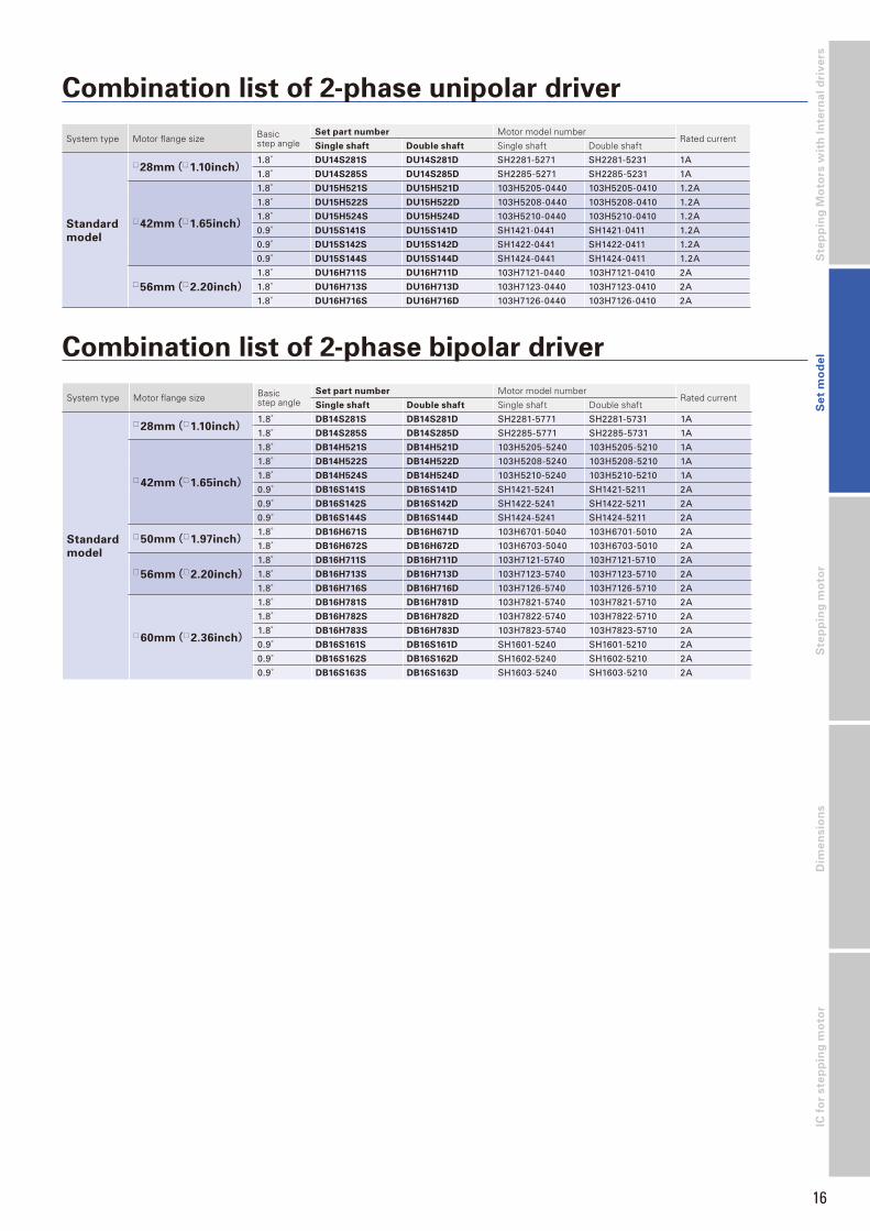
Combination list of 2-phase unipolar driver
System type Motor flange size Basic step angle
Set part number Motor model numberRated current
Single shaft Double shaft Single shaft Double shaft
Standard
model
□28mm(□1.10inch)1.8° DU14S281S DU14S281D SH2281-5271 SH2281-5231 1A
1.8° DU14S285S DU14S285D SH2285-5271 SH2285-5231 1A
□42mm(□1.65inch)
1.8° DU15H521S DU15H521D 103H5205-0440 103H5205-0410 1.2A
1.8° DU15H522S DU15H522D 103H5208-0440 103H5208-0410 1.2A
1.8° DU15H524S DU15H524D 103H5210-0440 103H5210-0410 1.2A
0.9° DU15S141S DU15S141D SH1421-0441 SH1421-0411 1.2A
0.9° DU15S142S DU15S142D SH1422-0441 SH1422-0411 1.2A
0.9° DU15S144S DU15S144D SH1424-0441 SH1424-0411 1.2A
□56mm(□2.20inch)1.8° DU16H711S DU16H711D 103H7121-0440 103H7121-0410 2A
1.8° DU16H713S DU16H713D 103H7123-0440 103H7123-0410 2A
1.8° DU16H716S DU16H716D 103H7126-0440 103H7126-0410 2A
Combination list of 2-phase bipolar driver
System type Motor flange size Basic step angle
Set part number Motor model numberRated current
Single shaft Double shaft Single shaft Double shaft
Standard
model
□28mm(□1.10inch)1.8° DB14S281S DB14S281D SH2281-5771 SH2281-5731 1A
1.8° DB14S285S DB14S285D SH2285-5771 SH2285-5731 1A
□42mm(□1.65inch)
1.8° DB14H521S DB14H521D 103H5205-5240 103H5205-5210 1A
1.8° DB14H522S DB14H522D 103H5208-5240 103H5208-5210 1A
1.8° DB14H524S DB14H524D 103H5210-5240 103H5210-5210 1A
0.9° DB16S141S DB16S141D SH1421-5241 SH1421-5211 2A
0.9° DB16S142S DB16S142D SH1422-5241 SH1422-5211 2A
0.9° DB16S144S DB16S144D SH1424-5241 SH1424-5211 2A
□50mm(□1.97inch)1.8° DB16H671S DB16H671D 103H6701-5040 103H6701-5010 2A
1.8° DB16H672S DB16H672D 103H6703-5040 103H6703-5010 2A
□56mm(□2.20inch)1.8° DB16H711S DB16H711D 103H7121-5740 103H7121-5710 2A
1.8° DB16H713S DB16H713D 103H7123-5740 103H7123-5710 2A
1.8° DB16H716S DB16H716D 103H7126-5740 103H7126-5710 2A
□60mm(□2.36inch)
1.8° DB16H781S DB16H781D 103H7821-5740 103H7821-5710 2A
1.8° DB16H782S DB16H782D 103H7822-5740 103H7822-5710 2A
1.8° DB16H783S DB16H783D 103H7823-5740 103H7823-5710 2A
0.9° DB16S161S DB16S161D SH1601-5240 SH1601-5210 2A
0.9° DB16S162S DB16S162D SH1602-5240 SH1602-5210 2A
0.9° DB16S163S DB16S163D SH1603-5240 SH1603-5210 2A

17
DC input
2-phase STEPPING SYSTEMS
Specifications
0.1 1 10 100
10 5000100 1000 2000 3000
fs
100 1000 2000 3000 5000
fs
14
0
12
10
8
6
4
2
1.0
0.8
0.6
0.4
0.2
0
So
urc
ecu
rren
t(A)
Pulse rate(kpulse/s)
Number of rotations(min-1)
2-division
1-division
0
0.02
0.04
0.06
0.08
0.1
To
rqu
e(kg
f・cm)
To
rqu
e(o
z・in)
To
rqu
e(N・
m)
012345678910
0.1 1 10 100
10 5000100 1000 2000 3000
fs
100 1000 2000 3000 5000
fs
14
0
12
10
8
6
4
2
1.0
0.8
0.6
0.4
0.2
0
So
urc
ecu
rren
t(A)
Pulse rate(kpulse/s)
Number of rotations(min-1)
2-division
1-division
0
0.02
0.04
0.06
0.08
0.1
To
rqu
e(kg
f・cm)
To
rqu
e(o
z・in)
To
rqu
e(N・
m)
012345678910
SizeMotor flange size □42mm(1.65inch)/0.9°Motor length 33mm(1.30inch) 39mm(1.54inch) 48mm(1.89inch)
Set partnumber
Single shaft DU15S141S DU15S142S DU15S144S
Double shaft DU15S141D DU15S142D DU15S144D
Holding torque N・m(oz・in) 0.2(28.32) 0.29(41.07) 0.39(55.23)
Rotor inertia ×10-4kg・m2(oz・in2) 0.044(0.24) 0.066(0.361) 0.089(0.487)
Mass(Weight) kg(lbs) 0.24(0.53) 0.29(0.64) 0.38(0.84)
Allowable thrust load N(lbs) 10(2.25) 10(2.25) 10(2.25)
Allowable radial load(Note 1) N(lbs) 30(6) 30(6) 30(6)
0.1 1 10 100
10 500030002000100 1000
fs
100 1000 2000 3000 5000
fs
28
0
24
20
16
12
8
4
2.0
1.6
1.2
0.4
0
So
urc
ecu
rren
t(A)
Pulse rate(kpulse/s)
Number of rotations(min-1)
2-division
1-division
0
0.04
0.08
0.12
0.16
0.2
To
rqu
e(kg
f・cm)
To
rqu
e(o
z・in)
To
rqu
e(N・
m)
012345678910
0.8
0.1 1 10 100
10 500030002000100 1000
fs
100 1000 2000 3000 5000
fs
28
0
24
20
16
12
8
4
2.0
1.6
1.2
0.4
0
So
urc
ecu
rren
t(A)
Pulse rate(kpulse/s)
Number of rotations(min-1)
2-division
1-division
0
0.04
0.08
0.12
0.16
0.2
To
rqu
e(kg
f・cm)
To
rqu
e(o
z・in)
To
rqu
e(N・
m)
012345678910
0.8
0.1 1 10 100fsfs
200030005000100 1000
200030005000100 1000
70
0
60
50
40
30
20
10
5
4
3
2
1
0
Torq
ue(
kgf・
cm)
Torq
ue(
oz・
in)
So
urc
e cu
rren
t(A)
Pulse rate(kpulse/s)
Number of rotations(min-1)
2-division
1-division
0
0.1
0.2
0.3
0.4
0.5
Torq
ue(
N・
m)
012345678910
0.1 1 10 100fsfs
200030005000100 1000
200030005000100 1000
70
0
60
50
40
30
20
10
5
4
3
2
1
0
Torq
ue(
kgf・
cm)
Torq
ue(
oz・
in)
So
urc
e cu
rren
t(A)
Pulse rate(kpulse/s)
Number of rotations(min-1)
2-division
1-division
0
0.1
0.2
0.3
0.4
0.5
Torq
ue(
N・
m)
012345678910
0.1 1 10 100fsfs
200030005000100 1000
200030005000100 1000
70
0
60
50
40
30
20
10
5
4
3
2
1
0
Torq
ue(
kgf・
cm)
Torq
ue(
oz・
in)
So
urc
e cu
rren
t(A)
Pulse rate(kpulse/s)
Number of rotations(min-1)
2-division
1-division
0
0.1
0.2
0.3
0.4
0.5
Torq
ue(
N・
m)
012345678910
0.1 1 10 100fsfs
200030005000100 1000
200030005000100 1000
70
0
60
50
40
30
20
10
5
4
3
2
1
0
Torq
ue(
kgf・
cm)
Torq
ue(
oz・
in)
So
urc
e cu
rren
t(A)
Pulse rate(kpulse/s)
Number of rotations(min-1)
2-division
1-division
0
0.1
0.2
0.3
0.4
0.5
Torq
ue(
N・
m)
012345678910
0.1 1 10 100fsfs
200030005000100 1000
200030005000100 1000
70
0
60
50
40
30
20
10
5
4
3
2
1
0
Torq
ue(
kgf・
cm)
Torq
ue(
oz・
in)
So
urc
e cu
rren
t(A)
Pulse rate(kpulse/s)
Number of rotations(min-1)
2-division
1-division
0
0.1
0.2
0.3
0.4
0.5
Torq
ue(
N・
m)
012345678910
0.1 1 10 100fsfs
200030005000100 1000
200030005000100 1000
70
0
60
50
40
30
20
10
5
4
3
2
1
0
Torq
ue(
kgf・
cm)
Torq
ue(
oz・
in)
So
urc
e cu
rren
t(A)
Pulse rate(kpulse/s)
Number of rotations(min-1)
2-division
1-division
0
0.1
0.2
0.3
0.4
0.5
Torq
ue(
N・
m)
012345678910
DC24V
DC36V
DC24V
DC36V
Standard modelF series driver + H or SH series motor
Unipolar
28 42 56
Motor flange size
(□1.65inch)(□1.10inch) (□2.20inch)
(Note1)When load is applied at 1/3 length from output shaft edge.
SizeMotor flange size □28mm(1.10inch)/1.8°Motor length 32mm(1.26inch) 51.5mm(2.03inch)
Set partnumber
Single shaft DU14S281S DU14S285S
Double shaft DU14S281D DU14S285D
Holding torque N・m(oz・in) 0.055(7.79) 0.115(16.28)
Rotor inertia ×10-4kg・m2(oz・in2) 0.01(0.05) 0.022(0.12)
Mass(Weight) kg(lbs) 0.11(0.24) 0.2(0.44)
Allowable thrust load N(lbs) 3(0.67) 3(0.67)
Allowable radial load(Note 1) N(lbs) 42(9.44) 49(11.02)
Pull-out torque
Source current (load applied)
Source current (no load)
Fs:Maximum self-start frequency when not loaded
1-division
2-division
Operating current:1A/phase
1-division fs
2-division fs
Pull-out torque
Source current (load applied)
Source current (no load)
Fs:Maximum self-start frequency when not loaded
1-division
2-division
Operating current:1.2A/phase
1-division fs
2-division fs
(Note1)When load is applied at 1/3 length from output shaft edge.
The date are measured under the drive condition of our company.The drive torque may very depending on the accuracy of customer-side equipment.
The date are measured under the drive condition of our company.The drive torque may very depending on the accuracy of customer-side equipment.

18
Dim
en
sio
ns
Ste
pp
ing
mo
tor
IC f
or
ste
pp
ing
mo
tor
Se
t m
od
el
Ste
pp
ing
Mo
tors
wit
h I
nte
rna
l d
riv
ers
□42mm(1.65inch)/1.8°33mm(1.30inch) 39mm(1.54inch) 48mm(1.89inch)
DU15H521S DU15H522S DU15H524S
DU15H521D DU15H522D DU15H524D
0.2(28.32) 0.3(42.48) 0.37(52.39)
0.036(0.20) 0.056(0.31) 0.072(0.34)
0.23(0.51) 0.29(0.64) 0.37(0.82)
10(2.25) 10(2.25) 10(2.25)
30(6) 30(6) 30(6)
0.1 1 10 100fsfs
20003000 5000100 1000
200030005000100 1000
70
0
60
50
40
30
20
10
5
4
3
2
1
0
Torq
ue(
kgf・
cm)
Torq
ue(
oz・
in)
So
urc
e cu
rren
t(A)
Pulse rate(kpulse/s)
Number of rotations(min-1)
2-division
1-division
0
0.1
0.2
0.3
0.4
0.5
Torq
ue(
N・
m)
012345678910
0.1 1 10 100fsfs
20003000 5000100 1000
200030005000100 1000
70
0
60
50
40
30
20
10
5
4
3
2
1
0
Torq
ue(
kgf・
cm)
Torq
ue(
oz・
in)
So
urc
ecu
rren
t(A)
Pulse rate(kpulse/s)
Number of rotations(min-1)
2-division
1-division
0
0.1
0.2
0.3
0.4
0.5
Torq
ue(
N・
m)
012345678910
0.1 1 10 100fsfs
20003000 5000100 1000
200030005000100 1000
70
0
60
50
40
30
20
10
5
4
3
2
1
0To
rqu
e(kg
f・cm)
So
urc
e cu
rren
t(A)
Pulse rate(kpulse/s)
Number of rotations(min-1)
2-division
1-division
0
0.1
0.2
0.3
0.4
0.5
Torq
ue(
N・
m)
012345678910
Torq
ue(
oz・
in)
0.1 1 10 100fsfs
20003000 5000100 1000
200030005000100 1000
70
0
60
50
40
30
20
10
5
4
3
2
1
0
Torq
ue(
kgf・
cm)
Torq
ue(
oz・
in)
So
urc
e cu
rren
t(A)
Pulse rate(kpulse/s)
Number of rotations(min-1)
2-division
1-division
0
0.1
0.2
0.3
0.4
0.5
Torq
ue(
N・
m)
012345678910
0.1 1 10 100fsfs
20003000 5000100 1000
200030005000100 1000
70
0
60
50
40
30
20
10
5
4
3
2
1
0
Torq
ue(
kgf・
cm)
Torq
ue(
oz・
in)
So
urc
e cu
rren
t(A)
Pulse rate(kpulse/s)
Number of rotations(min-1)
2-division
1-division
0
0.1
0.2
0.3
0.4
0.5
Torq
ue(
N・
m)
012345678910
0.1 1 10 100fsfs
20003000 5000100 1000
200030005000100 1000
70
0
60
50
40
30
20
10
5
4
3
2
1
0To
rqu
e(kg
f・cm)
Torq
ue(
oz・
in)
So
urc
e cu
rren
t(A)
Pulse rate(kpulse/s)
Number of rotations(min-1)
2-division
1-division
0
0.1
0.2
0.3
0.4
0.5
Torq
ue(
N・
m)
012345678910
0.1 1 10 100fsfs
20003000 5000100 1000
200030005000100 1000
70
0
60
50
40
30
20
10
5
4
3
2
1
0
Torq
ue(
kgf・
cm)
Torq
ue(
oz・
in)
So
urc
e cu
rren
t(A)
Pulse rate(kpulse/s)
Number of rotations(min-1)
2-division
1-division
0
0.1
0.2
0.3
0.4
0.5
Torq
ue(
N・
m)
012345678910
0.1 1 10 100fsfs
20003000 5000100 1000
200030005000100 1000
70
0
60
50
40
30
20
10
5
4
3
2
1
0
Torq
ue(
kgf・
cm)
Torq
ue(
oz・
in)
So
urc
e cu
rren
t(A)
Pulse rate(kpulse/s)
Number of rotations(min-1)
2-division
1-division
0
0.1
0.2
0.3
0.4
0.5
Torq
ue(
N・
m)
012345678910
0.1 1 10 100fsfs
140
0
120
100
80
60
40
20
10
8
6
4
2
0
So
urc
e cu
rren
t(A)
0
0.2
0.4
0.6
0.8
1.0
Torq
ue(
kgf・
cm)
Torq
ue(
oz・
in)
Torq
ue(
N・
m)
012345678910
Pulse rate(kpulse/s)
Number of rotations(min-1)
2-division
1-division20003000 5000100 1000
200030005000100 1000
0.1 1 10 100fsfs
140
0
120
100
80
60
40
20
10
8
6
4
2
0
So
urc
e cu
rren
t(A)
0
0.2
0.4
0.6
0.8
1.0
Torq
ue(
kgf・
cm)
Torq
ue(
oz・
in)
Torq
ue(
N・
m)
012345678910
Pulse rate(kpulse/s)
Number of rotations(min-1)
2-division
1-division20003000 5000100 1000
200030005000100 1000
0.1 1 10 100fs
20003000 5000100 1000
200030005000100 1000
280
0
240
200
160
120
80
40
20
16
12
8
4
0
So
urc
e cu
rren
t(A)
Pulse rate(kpulse/s)
Number of rotations(min-1)
2-division
1-division
0
0.4
0.8
1.2
1.6
2.0
To
rqu
e(kg
f・cm)
To
rqu
e(o
z・in)
To
rqu
e(N・
m)
012345678910
0.1 1 10 100fsfs
20003000 5000100 1000
200030005000100 1000
280
0
240
200
160
120
80
40
20
16
12
8
4
0
So
urc
e cu
rren
t(A)
Pulse rate(kpulse/s)
Number of rotations(min-1)
2-division
1-division
0
0.4
0.8
1.2
1.6
2.0
To
rqu
e(kg
f・cm)
To
rqu
e(o
z・in)
To
rqu
e(N・
m)
012345678910
DC24V
DC36V
(Note1)When load is applied at 1/3 length from output shaft edge.
SizeMotor flange size
Motor length
Set partnumber
Single shaft
Double shaft
Holding torque N・m(oz・in)
Rotor inertia ×10-4kg・m2(oz・in2)
Mass(Weight) kg(lbs)
Allowable thrust load N(lbs)
Allowable radial load(Note 1) N(lbs)
Pull-out torque
Source current (load applied)
Source current (no load)
Fs:Maximum self-start frequency when not loaded
1-division
2-division
Operating current:1.2A/phase
1-division fs
2-division fs
DC24V
DC36V
(Note1)When load is applied at 1/3 length from output shaft edge.
Pull-out torque
Source current (load applied)
Source current (no load)
Fs:Maximum self-start frequency when not loaded
1-division
2-division
Operating current:2A/phase
1-division fs
2-division fs
SizeMotor flange size □56mm(2.20inch)/1.8°Motor length 41.8mm(1.65inch) 53.8mm(2.12inch) 75.8mm(2.98inch)
Set partnumber
Single shaft DU16H711S DU16H713S DU16H716S
Double shaft DU16H711D DU16H713D DU16H716D
Holding torque N・m(oz・in) 0.39(55.23) 0.83(117.5) 1.27(179.8)
Rotor inertia ×10-4kg・m2(oz・in2) 0.1(0.55) 0.21(1.15) 0.36(1.97)
Mass(Weight) kg(lbs) 0.47(1.04) 0.63(1.39) 0.98(2.16)
Allowable thrust load N(lbs) 15(3.37) 15(3.37) 15(3.37)
Allowable radial load(Note 1) N(lbs) 71(15) 71(15) 71(15)

19
DC input
2-phase STEPPING SYSTEMS
Specifications
0.1 1 10 100
10 5000100 1000 2000 3000
fs
100 1000 2000 3000 5000
fs
14
0
12
10
8
6
4
2
1.0
0.8
0.6
0.4
0.2
0
So
urc
ecu
rren
t(A)
Pulse rate(kpulse/s)
Number of rotations(min-1)
2-division
1-division
0
0.02
0.04
0.06
0.08
0.1
To
rqu
e(kg
f・cm)
To
rqu
e(o
z・in)
To
rqu
e(N・
m)
012345678910
0.1 1 10 100
10 5000100 1000 2000 3000
fs
100 1000 2000 3000 5000
fs
14
0
12
10
8
6
4
2
1.0
0.8
0.6
0.4
0.2
0
So
urc
ecu
rren
t(A)
Pulse rate(kpulse/s)
Number of rotations(min-1)
2-division
1-division
0
0.02
0.04
0.06
0.08
0.1
To
rqu
e(kg
f・cm)
To
rqu
e(o
z・in)
To
rqu
e(N・
m)
012345678910
SizeMotor flange size □42mm(1.65inch)/0.9° □50mm(1.97inch)/1.8° □56mm(2.20inch)/1.8°Motor length 48mm(1.89inch) 39.8mm(1.57inch) 51.3mm(2.02inch) 41.8mm(1.65inch)
Set partnumber
Single shaft DB16S144S DB16H671S DB16H673S DB16H711S
Double shaft DB16S144D DB16H671D DB16H673D DB16H711D
Holding torque N・m(oz・in) 0.48(67.97) 0.28(39.6) 0.49(69.4) 0.39(55.2)
Rotor inertia ×10-4kg・m2(oz・in2) 0.089(0.487) 0.057(0.31) 0.118(0.65) 0.1(0.55)
Mass(Weight) kg(lbs) 0.38(0.84) 0.35(0.77) 0.5(1.10) 0.47(1.04)
Allowable thrust load N(lbs) 10(2.25) 15(3.37) 15(3.37) 15(3.37)
Allowable radial load(Note 1) N(lbs) 30(6) 99(22) 99(22) 71(15)
0.1 1 10 100
10 500030002000100 1000
fs
100 1000 2000 3000 5000
fs
28
0
24
20
16
12
8
4
2.0
1.6
1.2
0.4
0
So
urc
ecu
rren
t(A)
Pulse rate(kpulse/s)
Number of rotations(min-1)
2-division
1-division
0
0.04
0.08
0.12
0.16
0.2
To
rqu
e(kg
f・cm)
To
rqu
e(o
z・in)
To
rqu
e(N・
m)
012345678910
0.8
0.1 1 10 100
10 500030002000100 1000
fs
100 1000 2000 3000 5000
fs
28
0
24
20
16
12
8
4
2.0
1.6
1.2
0.4
0
So
urc
ecu
rren
t(A)
Pulse rate(kpulse/s)
Number of rotations(min-1)
2-division
1-division
0
0.04
0.08
0.12
0.16
0.2
To
rqu
e(kg
f・cm)
To
rqu
e(o
z・in)
To
rqu
e(N・
m)
012345678910
0.8
0.1 1 10 100
140
0
120
100
80
60
40
20
10
8
6
4
2
0
So
urc
e cu
rren
t(A)
0
0.2
0.4
0.6
0.8
1.0
Torq
ue(
kgf・
cm)
Torq
ue(
oz・
in)
Torq
ue(
N・
m)
012345678910
Pulse rate(kpulse/s)
Number of rotations(min-1)
2-division
1-division200030005000100 1000
200030005000100 1000
0.1 1 10 100
140
0
120
100
80
60
40
20
10
8
6
4
2
0
So
urc
e cu
rren
t(A)
0
0.2
0.4
0.6
0.8
1.0
Torq
ue(
kgf・
cm)
Torq
ue(
oz・
in)
Torq
ue(
N・
m)
012345678910
Pulse rate(kpulse/s)
Number of rotations(min-1)
2-division
1-division200030005000100 1000
200030005000100 1000
0.1 1 10 100fsfs
20003000 5000100 1000
200030005000100 1000
70
0
60
50
40
30
20
10
5
4
3
2
1
0
Torq
ue(
kgf・
cm)
Torq
ue(
oz・
in)
So
urc
e cu
rren
t(A)
Pulse rate(kpulse/s)
Number of rotations(min-1)
2-division
1-division
0
0.1
0.2
0.3
0.4
0.5
Torq
ue(
N・
m)
012345678910
0.1 1 10 100fsfs
20003000 5000100 1000
200030005000100 1000
70
0
60
50
40
30
20
10
5
4
3
2
1
0
Torq
ue(
kgf・
cm)
Torq
ue(
oz・
in)
So
urc
e cu
rren
t(A)
Pulse rate(kpulse/s)
Number of rotations(min-1)
2-division
1-division
0
0.1
0.2
0.3
0.4
0.5
Torq
ue(
N・
m)
012345678910
0.1 1 10 100fsfs
140
0
120
100
80
60
40
20
10
8
6
4
2
0
So
urc
e cu
rren
t(A)
0
0.2
0.4
0.6
0.8
1.0
Torq
ue(
kgf・
cm)
Torq
ue(
oz・
in)
Torq
ue(
N・
m)
012345678910
Pulse rate(kpulse/s)
Number of rotations(min-1)
2-division
1-division20003000 5000100 1000
200030005000100 1000
0.1 1 10 100fsfs
140
0
120
100
80
60
40
20
10
8
6
4
2
0
So
urc
e cu
rren
t(A)
0
0.2
0.4
0.6
0.8
1.0
Torq
ue(
kgf・
cm)
Torq
ue(
oz・
in)
Torq
ue(
N・
m)
012345678910
Pulse rate(kpulse/s)
Number of rotations(min-1)
2-division
1-division20003000 5000100 1000
200030005000100 1000
0.1 1 10 100fsfs
20003000 5000100 1000
200030005000100 1000
140
0
120
100
80
60
40
20
10
8
6
4
2
0
So
urc
e cu
rren
t(A)
0
0.2
0.4
0.6
0.8
1.0
Torq
ue(
kgf・
cm)
Torq
ue(
oz・
in)
Torq
ue(
N・
m)
012345678910
Pulse rate(kpulse/s)
Number of rotations(min-1)
2-division
1-division
0.1 1 10 100fsfs
140
0
120
100
80
60
40
20
10
8
6
4
2
0
So
urc
e cu
rren
t(A)
0
0.2
0.4
0.6
0.8
1.0
Torq
ue(
kgf・
cm)
Torq
ue(
oz・
in)
Torq
ue(
N・
m)
012345678910
Pulse rate(kpulse/s)
Number of rotations(min-1)
2-division
1-division20003000 5000100 1000
200030005000100 1000
DC24V
DC36V
DC24V
DC36V
Standard modelF series driver + H or SH series motor
Bipolar
28 42 50
Motor flange size
56 60
(□1.65inch) (□1.97inch) (□2.20inch) (□2.36inch)(□1.10inch)
Pull-out torque
Source current (load applied)
Source current (no load)
Fs:Maximum self-start frequency when not loaded
1-division
2-division
Operating current□28mm (1.10inch)/1.8°:1A/phase□42mm (1.65inch)/1.8°:1A/phase□42mm (1.65inch)/0.9°:2A/phase
1-division fs
2-division fs
SizeMotor flange size □28mm(1.10inch)/1.8°Motor length 32mm(1.26inch) 51.5mm(2.03inch)
Set partnumber
Single shaft DB14S281S DB14S285S
Double shaft DB14S281D DB14S285D
Holding torque N・m(oz・in) 0.07(9.91) 0.145(20.53)
Rotor inertia ×10-4kg・m2(oz・in2) 0.01(0.05) 0.022(0.12)
Mass(Weight) kg(lbs) 0.11(0.24) 0.2(0.44)
Allowable thrust load N(lbs) 3(0.67) 3(0.67)
Allowable radial load(Note 1) N(lbs) 42(9.44) 49(9.44)(Note1)When load is applied at 1/3 length from output shaft edge.
Pull-out torque
Source current (load applied)
Source current (no load)
Fs:Maximum self-start frequency when not loaded
1-division
2-division
Operating current:2A/phase
1-division fs
2-division fs
(Note1)When load is applied at 1/3 length from output shaft edge.
The date are measured under the drive condition of our company.The drive torque may very depending on the accuracy of customer-side equipment.
The date are measured under the drive condition of our company. The drive torque may very depending on the accuracy of customer-side equipment.

20
Dim
en
sio
ns
Ste
pp
ing
mo
tor
IC f
or
ste
pp
ing
mo
tor
Se
t m
od
el
Ste
pp
ing
Mo
tors
wit
h I
nte
rna
l d
riv
ers
□42mm(1.65inch)/1.8°33mm(1.30inch) 39mm(1.54inch) 48mm(1.89inch)
DB14H521S DB14H522S DB14H524S
DB14H521D DB14H522D DB14H524D
0.265(37.53) 0.39(55.23) 0.51(72.22)
0.036(0.20) 0.056(0.31) 0.072(0.34)
0.23(0.51) 0.29(0.64) 0.37(0.82)
10(2.25) 10(2.25) 10(2.25)
30(6) 30(6) 30(6)
0.1 1 10 100fsfs
20003000 5000100 1000
200030005000100 1000
70
0
60
50
40
30
20
10
5
4
3
2
1
0
Torq
ue(
kgf・
cm)
Torq
ue(
oz・
in)
So
urc
e cu
rren
t(A)
Pulse rate(kpulse/s)
Number of rotations(min-1)
2-division
1-division
0
0.1
0.2
0.3
0.4
0.5
Torq
ue(
N・
m)
012345678910
0.1 1 10 100fsfs
20003000 5000100 1000
200030005000100 1000
70
0
60
50
40
30
20
10
5
4
3
2
1
0
Torq
ue(
kgf・
cm)
Torq
ue(
oz・
in)
So
urc
e cu
rren
t(A)
Pulse rate(kpulse/s)
Number of rotations(min-1)
2-division
1-division
0
0.1
0.2
0.3
0.4
0.5
Torq
ue(
N・
m)
012345678910
0.1 1 10 100fsfs
20003000 5000100 1000
200030005000100 1000
70
0
60
50
40
30
20
10
5
4
3
2
1
0
Torq
ue(
kgf・
cm)
Torq
ue(
oz・
in)
So
urc
e cu
rren
t(A)
Pulse rate(kpulse/s)
Number of rotations(min-1)
2-division
1-division
0
0.1
0.2
0.3
0.4
0.5
Torq
ue(
N・
m)
012345678910
0.1 1 10 100fsfs
20003000 5000100 1000
200030005000100 1000
70
0
60
50
40
30
20
10
5
4
3
2
1
0
Torq
ue(
kgf・
cm)
Torq
ue(
oz・
in)
So
urc
e cu
rren
t(A)
Pulse rate(kpulse/s)
Number of rotations(min-1)
2-division
1-division
0
0.1
0.2
0.3
0.4
0.5
Torq
ue(
N・
m)
012345678910
0.1 1 10 100fsfs
140
0
120
100
80
60
40
20
10
8
6
4
2
0
So
urc
e cu
rren
t(A)
0
0.2
0.4
0.6
0.8
1.0
Torq
ue(
kgf・
cm)
Torq
ue(
oz・
in)
Torq
ue(
N・
m)
012345678910
Pulse rate(kpulse/s)
Number of rotations(min-1)
2-division
1-division20003000 5000100 1000
200030005000100 1000
0.1 1 10 100fsfs
140
0
120
100
80
60
40
20
10
8
6
4
2
0
So
urc
e cu
rren
t(A)
0
0.2
0.4
0.6
0.8
1.0
Torq
ue(
kgf・
cm)
Torq
ue(
oz・
in)
Torq
ue(
N・
m)
012345678910
Pulse rate(kpulse/s)
Number of rotations(min-1)
2-division
1-division20003000 5000100 1000
200030005000100 1000
0.1 1 10 100fsfs
200030005000100 1000
200030005000100 1000
70
0
60
50
40
30
20
10
5
4
3
2
1
0
Torq
ue(
kgf・
cm)
Torq
ue(
oz・
in)
So
urc
e cu
rren
t(A)
Pulse rate(kpulse/s)
Number of rotations(min-1)
2-division
1-division
0
0.1
0.2
0.3
0.4
0.5
Torq
ue(
N・
m)
012345678910
0.1 1 10 100fsfs
200030005000100 1000
200030005000100 1000
70
0
60
50
40
30
20
10
5
4
3
2
1
0To
rqu
e(kg
f・cm)
Torq
ue(
oz・
in)
So
urc
e cu
rren
t(A)
Pulse rate(kpulse/s)
Number of rotations(min-1)
2-division
1-division
0
0.1
0.2
0.3
0.4
0.5
Torq
ue(
N・
m)
012345678910
0.1 1 10 100fsfs
200030005000100 1000
200030005000100 1000
70
0
60
50
40
30
20
10
5
4
3
2
1
0
Torq
ue(
kgf・
cm)
Torq
ue(
oz・
in)
So
urc
e cu
rren
t(A)
Pulse rate(kpulse/s)
Number of rotations(min-1)
2-division
1-division
0
0.1
0.2
0.3
0.4
0.5
Torq
ue(
N・
m)
012345678910
0.1 1 10 100fsfs
200030005000100 1000
200030005000100 1000
70
0
60
50
40
30
20
10
5
4
3
2
1
0
Torq
ue(
kgf・
cm)
Torq
ue(
oz・
in)
So
urc
e cu
rren
t(A)
Pulse rate(kpulse/s)
Number of rotations(min-1)
2-division
1-division
0
0.1
0.2
0.3
0.4
0.5
Torq
ue(
N・
m)
012345678910
□56mm(2.20inch)/1.8° □60mm(2.36inch)/1.8°
53.8mm(2.12inch) 75.8mm(2.98inch) 44.8mm(1.76inch) 53.8mm(2.12inch) 85.8mm(3.38inch)
DB16H713S DB16H716S DB16H781S DB16H782S DB16H783S
DB16H713D DB16H716D DB16H781D DB16H782D DB16H783D
0.83(117.5) 1.27(179.8) 0.88(124.6) 1.37(194.0) 2.7(382.3)
0.21(1.15) 0.36(1.97) 0.275(1.50) 0.4(2.19) 0.84(4.59)
0.65(1.43) 0.98(2.16) 0.6(1.32) 0.77(1.70) 1.34(2.95)
15(3.37) 15(3.37) 15(3.37) 15(3.37) 15(3.37)
71(15) 71(15) 95(21) 95(21) 95(21)
0.1 1 10 100fsfs
20003000 5000100 1000
200030005000100 1000
280
0
240
200
160
120
80
40
20
16
12
8
4
0
So
urc
e cu
rren
t(A)
Pulse rate(kpulse/s)
Number of rotations(min-1)
2-division
1-division
0
0.4
0.8
1.2
1.6
2.0
To
rqu
e(kg
f・cm)
To
rqu
e(o
z・in)
To
rqu
e(N・
m)
012345678910
0.1 1 10 100fsfs
20003000 5000100 1000
200030005000100 1000
280
0
240
200
160
120
80
40
20
16
12
8
4
0
So
urc
e cu
rren
t(A)
Pulse rate(kpulse/s)
Number of rotations(min-1)
2-division
1-division
0
0.4
0.8
1.2
1.6
2.0
To
rqu
e(kg
f・cm)
To
rqu
e(o
z・in)
To
rqu
e(N・
m)
012345678910
0.1 1 10 100fsfs
20003000 5000100 1000
200030005000100 1000
280
0
240
200
160
120
80
40
20
16
12
8
4
0
So
urc
e cu
rren
t(A)
Pulse rate(kpulse/s)
Number of rotations(min-1)
2-division
1-division
0
0.4
0.8
1.2
1.6
2.0
To
rqu
e(kg
f・cm)
To
rqu
e(o
z・in)
To
rqu
e(N・
m)
012345678910
0.1 1 10 100fsfs
20003000 5000100 1000
200030005000100 1000
280
0
240
200
160
120
80
40
20
16
12
8
4
0
So
urc
e cu
rren
t(A)
Pulse rate(kpulse/s)
Number of rotations(min-1)
2-division
1-division
0
0.4
0.8
1.2
1.6
2.0
To
rqu
e(kg
f・cm)
To
rqu
e(o
z・in)
To
rqu
e(N・
m)
012345678910
0.1 1 10 100fsfs
20003000 5000100 1000
200030005000100 1000
280
0
240
200
160
120
80
40
20
16
12
8
4
0
So
urc
e cu
rren
t(A)
Pulse rate(kpulse/s)
Number of rotations(min-1)
2-division
1-division
0
0.4
0.8
1.2
1.6
2.0
To
rqu
e(kg
f・cm)
To
rqu
e(o
z・in)
To
rqu
e(N・
m)
012345678910
0.1 1 10 100fsfs
20003000 5000100 1000
200030005000100 1000
280
0
240
200
160
120
80
40
20
16
12
8
4
0
So
urc
e cu
rren
t(A)
Pulse rate(kpulse/s)
Number of rotations(min-1)
2-division
1-division
0
0.4
0.8
1.2
1.6
2.0
To
rqu
e(kg
f・cm)
To
rqu
e(o
z・in)
To
rqu
e(N・
m)
012345678910
0.1 1 10 100fsfs
20003000 5000100 1000
200030005000100 1000
280
0
240
200
160
120
80
40
20
16
12
8
4
0
So
urc
e cu
rren
t(A)
Pulse rate(kpulse/s)
Number of rotations(min-1)
2-division
1-division
0
0.4
0.8
1.2
1.6
2.0
To
rqu
e(kg
f・cm)
To
rqu
e(o
z・in)
To
rqu
e(N・
m)
012345678910
0.1 1 10 100fsfs
20003000 5000100 1000
200030005000100 1000
280
0
240
200
160
120
80
40
20
16
12
8
4
0
So
urc
e cu
rren
t(A)
Pulse rate(kpulse/s)
Number of rotations(min-1)
2-division
1-division
0
0.4
0.8
1.2
1.6
2.0
To
rqu
e(kg
f・cm)
To
rqu
e(o
z・in)
To
rqu
e(N・
m)
012345678910
0.1 1 10 100fsfs
20003000 5000100 1000
200030005000100 1000
700
0
600
500
400
300
200
100
50
40
30
20
10
0
Torq
ue(
kgf・
cm)
Torq
ue(
oz・
in)
So
urc
e cu
rren
t(A)
Pulse rate(kpulse/s)
Number of rotations(min-1)
2-division
1-division
0
1
2
3
4
5
Torq
ue(
N・
m)
012345678910
0.1 1 10 100fsfs
20003000 5000100 1000
200030005000100 1000
700
0
600
500
400
300
200
100
50
40
30
20
10
0
Torq
ue(
kgf・
cm)
Torq
ue(
oz・
in)
So
urc
e cu
rren
t(A)
Pulse rate(kpulse/s)
Number of rotations(min-1)
2-division
1-division
0
1
2
3
4
5
Torq
ue(
N・
m)
012345678910
□42mm(1.65inch)/0.9°33mm(1.30inch) 39mm(1.54inch)
DB16S141S DB16S142S
DB16S141D DB16S142D
0.23(32.57) 0.34(48.15)
0.044(0.24) 0.066(0.361)
0.24(0.53) 0.29(0.64)
10(2.25) 10(2.25)
30(6) 30(6)
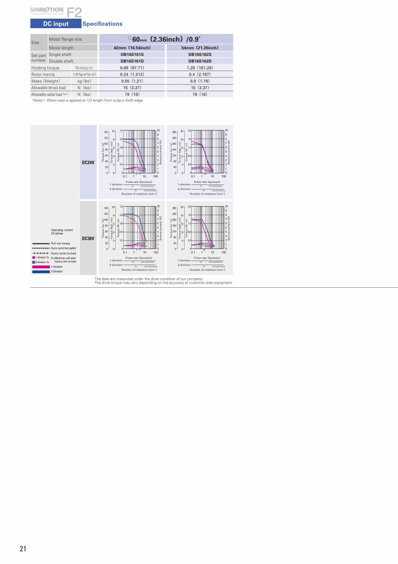
21
DC input
2-phase STEPPING SYSTEMS
Specifications
0.1 1 10 100fsfs
140
0
120
100
80
60
40
20
10
8
6
4
2
0
So
urc
e cu
rren
t(A)
0
0.2
0.4
0.6
0.8
1.0
Torq
ue(
kgf・
cm)
Torq
ue(
oz・
in)
Torq
ue(
N・
m)
012345678910
Pulse rate(kpulse/s)
Number of rotations(min-1)
2-division
1-division200030005000100 1000
200030005000100 1000
0.1 1 10 100fsfs
140
0
120
100
80
60
40
20
10
8
6
4
2
0
So
urc
e cu
rren
t(A)
0
0.2
0.4
0.6
0.8
1.0
Torq
ue(
kgf・
cm)
Torq
ue(
oz・
in)
Torq
ue(
N・
m)
012345678910
Pulse rate(kpulse/s)
Number of rotations(min-1)
2-division
1-division200030005000100 1000
200030005000100 1000
0.1 1 10 100fsfs
280
0
240
200
160
120
80
40
20
16
12
8
4
0
So
urc
e cu
rren
t(A)
0
0.4
0.8
1.2
1.6
2.0
To
rqu
e(kg
f・cm)
To
rqu
e(o
z・in)
To
rqu
e(N・
m)
012345678910
Pulse rate(kpulse/s)
Number of rotations(min-1)
2-division
1-division200030005000100 1000
200030005000100 1000
0.1 1 10 100fsfs
200030005000100 1000
200030005000100 1000
280
0
240
200
160
120
80
40
20
16
12
8
4
0
So
urc
e cu
rren
t(A)
Pulse rate(kpulse/s)
Number of rotations(min-1)
2-division
1-division
0
0.4
0.8
1.2
1.6
2.0
To
rqu
e(kg
f・cm)
To
rqu
e(o
z・in)
To
rqu
e(N・
m)
012345678910
DC24V
DC36VPull-out torque
Source current (load applied)
Source current (no load)
Fs:Maximum self-start frequency when not loaded
1-division
2-division
Operating current:2A/phase
1-division fs
2-division fs
SizeMotor flange size □60mm(2.36inch)/0.9°Motor length 42mm(16.54inch) 54mm(21.26inch)
Set partnumber
Single shaft DB16S161S DB16S162S
Double shaft DB16S161D DB16S162D
Holding torque N・m(oz・in) 0.69(97.71) 1.28(181.26)
Rotor inertia ×10-4kg・m2(oz・in2) 0.24(1.312) 0.4(2.187)
Mass(Weight) kg(lbs) 0.55(1.21) 0.8(1.76)
Allowable thrust load N(lbs) 15(3.37) 15(3.37)
Allowable radial load(Note 1) N(lbs) 79(18) 79(18)(Note1)When load is applied at 1/3 length from output shaft edge.
The date are measured under the drive condition of our company.The drive torque may very depending on the accuracy of customer-side equipment.
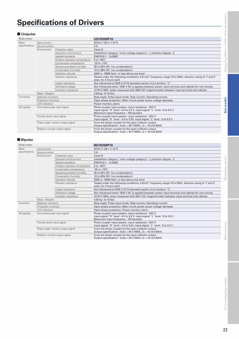
22
Dim
en
sio
ns
Ste
pp
ing
mo
tor
IC f
or
ste
pp
ing
mo
tor
Se
t m
od
el
Ste
pp
ing
Mo
tors
wit
h I
nte
rna
l d
riv
ers
Specifications of Drivers
■ Unipolar
■ Bipolar
Model number US1D200P10Basic specifications
Input source DC24 V / 36 V±10 %Source current 3 AEnvironment Protection class Class III
Operation environment Installation category(over-voltage category) : I, pollution degree : 2Applied standards EN61010-1,UL508CAmbient operation temperature 0 to +50℃Conservation temperature -20 to +70℃Operating ambient humidity 35 to 85% RH(no condensation)Conservation humidity 10 to 90% RH(no condensation)Operation altitude 2000 m(6560 feet)or less above sea levelVibration resistance Tested under the following conditions; 4.9 m/s2, frequency range 10 to 55Hz, direction along X, Y and Z
axes, for 2 hours eachImpact resistance Not influenced at NDS-C-0110 standard section 3.2.2 division “C” .Withstand voltage Not influenced when 1500 V AC is applied between power input terminal and cabinet for one minute.Insulation resistance 10 MΩ MIN. when measured with 500V DC megohmmeter between input terminal and cabinet.
Mass(Weight) 0.08 kg(0.18 lbs)Functions Selection functions Step angle, Pulse input mode, Step current, Operating current.
Protection functions Open phase protection, Main circuit power souce voltage decreaseLED indication Power monitor, alarm
I/O signals Command pulse input signal Photo-coupler input system, input resistance : 220Ωinput-signal “H” level : 4.0 to 5.5 V, input-signal “L” level : 0 to 0.5 VMaximum input frequency : 150 kpulse/s
Poweer down input signal Photo-coupler input system, input resistance : 220Ωinput-signal “H” level : 4.0 to 5.5V, input-signal “L” level : 0 to 0.5 V
Phase origin monitor output signal From the photo coupler by the open collector outputOutput specification : Vceo = 40 V MAX., Ic = 10 mA MAX.
Rotation monitor output signal From the photo coupler by the open collector outputOutput specification : Vceo = 40 V MAX., Ic = 10 mA MAX.
Model number BS1D200P10Basic specifications
Input source DC24 V / 36 V±10 %Source current 3 AEnvironment Protection class Class III
Operation environment Installation category(over-voltage category) : I, pollution degree : 2Applied standards EN61010-1,UL508CAmbient operation temperature 0 to +50℃Conservation temperature -20 to +70℃Operating ambient humidity 35 to 85% RH(no condensation)Conservation humidity 10 to 90% RH(no condensation)Operation altitude 2000 m(6560 feet)or less above sea levelVibration resistance Tested under the following conditions; 4.9m/s2, frequency range 10 to 55Hz, direction along X, Y and Z
axes, for 2 hours eachImpact resistance Not influenced at NDS-C-0110 standard section 3.2.2 division “C” .Withstand voltage Not influenced when 1500 V AC is applied between power input terminal and cabinet for one minute.Insulation resistance 10 MΩ MIN. when measured with 500 V DC megohmmeter between input terminal and cabinet.
Mass(Weight) 0.08 kg(0.18 lbs)Functions Selection functions Step angle, Pulse input mode, Step current, Operating current.
Protection functions Open phase protection, Main circuit power souce voltage decreaseLED indication Open phase protection, Power monitor, alarm
I/O signals Command pulse input signal Photo-coupler input system, input resistance : 220Ωinput-signal “H” level : 4.0 to 5.5 V, input-signal “L” level : 0 to 0.5 V Maximum input frequency : 150 kpulse/s
Poweer down input signal Photo-coupler input system, input resistance : 220Ωinput-signal “H” level : 4.0 to 5.5V, input-signal “L” level : 0 to 0.5 V
Phase origin monitor output signal From the photo coupler by the open collector outputOutput specification : Vceo = 40 V MAX., Ic = 10 mA MAX.
Rotation monitor output signal From the photo coupler by the open collector outputOutput specification : Vceo = 40 V MAX., Ic = 10 mA MAX.

2323
Operation, Connection, and Function
■ Each section name of the drivers
Unipolar
Bipolar
7 5 4
3
16
2
5
3
6
2
4
1
7
Signal name CN1 Pin number Function
CW pulse input(standard)
12
When using “2-input mode”Drive pulse for the CW direction rotation is input.
Pulse column input12
When using “Pulse and direction mode”Drive pulse train for the stepping motor rotation is input.
CCW pulse input(standard)
34
When using “2-input mode”Drive pulse for the CCW direction rotation is input.
Rotation direction input
34
The rotation direction signal of stepping motor is input for the “Pulse and direction mode”.Internal photocoupler ON…CW directionInternal photocoupler OFF…CCW direction
Power down input56
Inputting the PD signal cuts OFF the current flowing through the stepping motor.Iinternal photocoupler ON…PD function enabledIinternal photocoupler OFF…PD function disabled
Phase origin monitor output
78
It is turned ON when the excitation phase is at the origin(in the state when the power is turned ON)It is turned ON once per 4 pulses when setting to HALF step.It is turned ON once per 8 pulses when setting to FULL step.
Alarm output9
10
The signal is externally output when one of several alarm circuits operates in the PM driver. At this time, the stepping motor is in the unexcited state.
■ Specification summary of CN1 I/O signal
The CW rotation direction of stepping motor means the clockwise direction rotation as viewed from the output shaft side(flange side). The CCW rotation direction means the counterclockwise direction rotation as viewed from the output shaft side(flange side).
1 Driving current selection switch (RUN)You can select the value of the motorcurrent when driving.
2 Function selection DIP switchpack
Select the function dependingon your specification.
3 LED for power supply monitor(POW)Lit up when the main circuit powersupply is connected.
Dial 0 1 2 3 4 5 6 7Stepping motor current(A) 2.0 1.9 1.8 1.7 1.6 1.5 1.4 1.3
Dial 8 9 A B C D E FStepping motor current(A) 1.2 1.1 1.0 0.9 0.8 0.7 0.6 0.5
The factory setting is F (0.5A).Select the current after checking the rated current of the combination motor.
Indicator Explanation“POW” is
displayed. Main circuit power supply is switched on.
1 Driving current selection switch (RUN)You can select the value of the motorcurrent when driving.
2 Function selection DIP switchpack
Select the function dependingon your specification.
3 LED for power supply monitor(POW)Lit up when the main circuit powersupply is connected.
Indicator Explanation
“ALM” is displayed.
Motor cable is broken, or switching element in driver is faulty. The main circuit voltage is out of specifications range (Less than DC19V).
When “ALM” is displayed, the winding current of the stepping motor is cut off and it is in a “non-excitation” state. At the same time, an output signal is transmitted from the alarm output terminal (AL) to an external source. When the alarm circuit is operating, this state is maintained until it is reset by switching on the power supply again. When an alarm condition has occurred, please take corrective actions to rectify the cause of the alarm before switching on the power supply again.
4 LED for alarm display (ALM)Lit when an alarm is generated.
5 I/O signal connector(CN1)Connect the I/O signal.
6 Motor connector (CN2)Connect the motor’ s power line.
7 Power supply connector (CN3)Connect the main circuitpower supply.
Dial 0 1 2 3 4 5 6 7Stepping motor current(A) 2.0 1.9 1.8 1.7 1.6 1.5 1.4 1.3
Dial 8 9 A B C D E FStepping motor current(A) 1.2 1.1 1.0 0.9 0.8 0.7 0.6 0.5
The factory setting is F (0.5A).Select the current after checking the rated current of the combination motor.
Indicator Explanation“POW” is
displayed. Main circuit power supply is switched on.
Indicator Explanation
“ALM” is displayed.
Motor cable is broken, or switching element in driver is faulty. The main circuit voltage is out of specifications range (Less than DC19V).
When “ALM” is displayed, the winding current of the stepping motor is cut off and it is in a “non-excitation” state. At the same time, an output signal is transmitted from the alarm output terminal (AL) to an external source. When the alarm circuit is operating, this state is maintained until it is reset by switching on the power supply again. When an alarm condition has occurred, please take corrective actions to rectify the cause of the alarm before switching on the power supply again.
4 LED for alarm display (ALM)Lit when an alarm is generated.
5 I/O signal connector(CN1)Connect the I/O signal.
6 Motor connector (CN2)Connect the motor’ s power line.
7 Power supply connector (CN3)Connect the main circuitpower supply.
DC input
2-phase STEPPING SYSTEMS
Specifications

24
Dim
en
sio
ns
Ste
pp
ing
mo
tor
IC f
or
ste
pp
ing
mo
tor
24
Se
t m
od
el
Ste
pp
ing
Mo
tors
wit
h I
nte
rna
l d
riv
ers
Input circuit configuration(CW and CCW Pulse input)
EX1 EX2 EX3 Partition numberON ON ON 1-divisionOFF ON OFF 2-divisionON OFF OFF 4-divisionOFF OFF OFF 8-divisionOFF OFF ON 16-division
Step angle select (EX1、EX2、EX3)Select the partition number of the basic step angle.
Unipolar
External wiring diagram
Functions can be selected according to the specification with the dip switch.Check that the ex-factory settings are as follows.
EX1
EX2
EX3
F/R
ACD1
ACD2
LV
EORG
OFF
OFF Partition number: 8
OFF
OFF Input method 2 (CW/CCW pulse input)
OFF Stopping current: 40% of driving current
OFF
OFF Micro step operation
OFF Phase origin
OFF ON
Bipolar
Part Wire size Allowable wire length
For power supply AWG22(0.3 mm2) 2 m MAX.
For input/output signal
AWG24(0.2 mm2) to AWG22(0.3 mm2) 2 m MAX.
For motor AWG22(0.3 mm2) 3 m MAX.
■ Applicable Wire Sizes
DC24G/36G
DC24V/36V
22
4
1
2
5
6
7
8
9
10
CN3
3M
6
5
4
3
1
CN1
1
CN2
11
DC24V/36V
DC24G/36G
3
4
2
4
CN3
10
9
8
7
6
5
2
1
3
2
CN2CN1
MPulse input (CW[CK])
Pulse input (CCW[U/D])
Power down input (PD)
Phase origin monitoroutput (MON)
Alarm output (AL)
Pulse input (CW[CK])
Pulse input (CCW[U/D])
Power down input (PD)
Phase origin monitoroutput (MON)
Alarm output (AL)
White
Black
Orange
Blue
Red
Yellow
Orange
Blue
Red
Yellow
F / R Input pulse typeON 1 input(Pluse&direction)OFF 2 input(CW, CCW)
Input method select(F/R)Selects input pulse type
ACD2 ACD1 Current value of the motorON ON 100% of driving currentON OFF 60% of driving currentOFF ON 50% of driving currentOFF OFF 40% of driving current
Current selection when stopping (ACD1、ACD2)Select the current value of the motor when stopping.
LV OperationON Auto-micro functionOFF Micro-step
Low-vibration mode select(LV)Provides low-vibration, smooth operation even if resolution is rough(1-division, 2-division, etc)
EORG Original excitation phaseON Excitation phase at power shut offOFF Phase origin
Excitation select(EORG)The excitation phase when the power supply is turned on is selected.
2
5 6
Initial configuration of factory shipment is set to 40% of rated value. Driver and motor should be operated at around 50% of rated value to reduce heat.
By turning on the EORG, excitation phase when power OFF will besaved. Therefore, there will be no shaft displacement when turningthe power ON.
7

2525
2-input mode(CW, CCW)
■ Timing of the command pulse
Input circuit configuration of CW(CK), CCW(U/D)• Pulse duty 50% MAX.
• Maximum input frequency:150kpulse/s
• When the crest value of the input signal exceeds 5V, use the external limit resistance R to limit the input current to approximately 15mA.
■ Input signal specifications
1μs MAX.
3μs MIN.
1μs MAX.
90%4.0 to 5.5V
0 to 0.5V
Rotation
50%
10%
Photo coupler type
50μs . MIN.
ON
OFF
ON
OFF
1 input type(CW, CCW)
50μs . MIN. 10μs . MIN.
ON
OFF
ON
OFF
• Shaded area indicates internal photo coupler “ON” . Internal circuit (motor) starts operating at leading edge of the photo coupler “ON” .
• To apply pulse to CW, set CCW side internal photo coupler to “OFF” .
• To apply pulse to CCW, set CW side internal photo coupler to “OFF” .
• Shaded area indicates internal photo coupler “ON” . Internal circuit (motor) starts operating at leading edge of CK side photo coupler “ON”.
• Switching of U/D input signal must be done while CK side internal photo coupler is “OFF”.
+5V1(3)
2(4)
R
220Ω
1000pF
Input signal
Driver
Specifications
2-phase STEPPING SYSTEMS
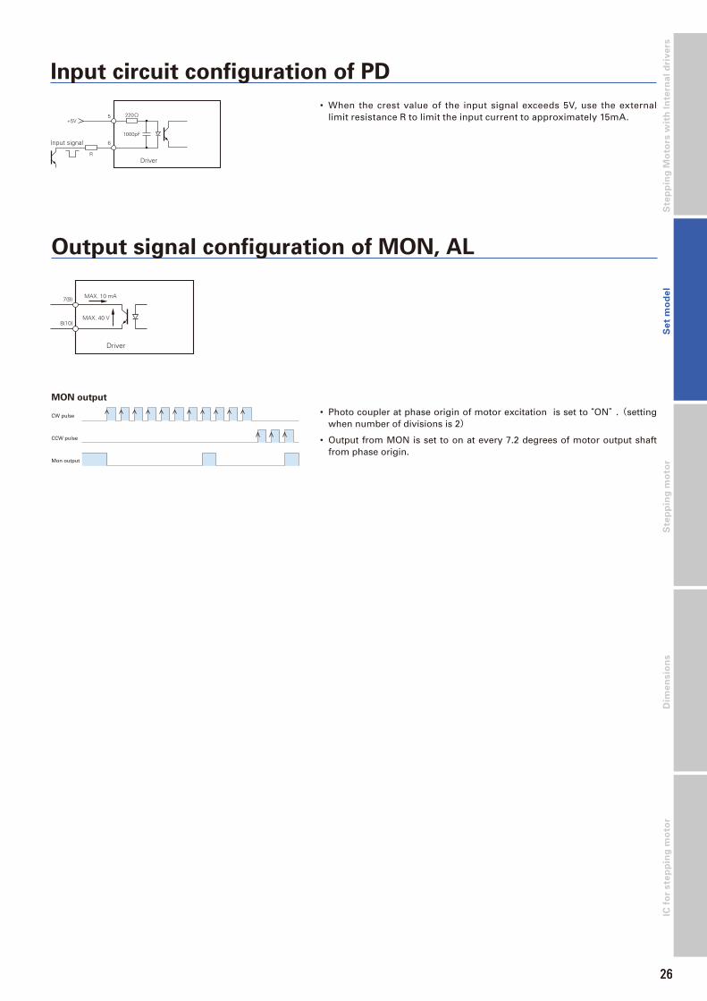
26
Dim
en
sio
ns
Ste
pp
ing
Mo
tors
wit
h I
nte
rna
l d
riv
ers
S
tep
pin
g m
oto
rIC
fo
r ste
pp
ing
mo
tor
26
Se
t m
od
el
+5V5
6
R
220Ω
1000pF
Input signal
Driver
• When the crest value of the input signal exceeds 5V, use the external limit resistance R to limit the input current to approximately 15mA.
MON output
Output signal configuration of MON, AL
Driver
7(9)
8(10)
MAX. 10 mA
MAX. 40 V
CW pulse
CCW pulse
Mon output
• Photo coupler at phase origin of motor excitation is set to “ON” .(setting when number of divisions is 2)
• Output from MON is set to on at every 7.2 degrees of motor output shaft from phase origin.
Input circuit configuration of PD

27
2-phase stepping motor
28mmsq.(1.10inch sq.)SH228□1.8°/step
Bipolar winding・Lead wire type
Model Holding torque at 2-phase energization Rated current Wiring resistance Winding inductance Rotor inertia Mass(Weight)
Single shaft Double shafts [N・m (oz・in)MIN.] A/phase Ω /phase mH/phase [×10- 4kg・m2(oz・in2)] [kg(Ibs)]
SH2281-5671 -5631 0.07(9.91) 0.5 10.5 7.2 0.01(0.05) 0.11(0.24)
SH2281-5771 -5731 0.07(9.91) 1 2.6 1.85 0.01(0.05) 0.11(0.24)
SH2285-5671 -5631 0.145(20.53) 0.5 15 13.5 0.022(0.12) 0.2(0.44)
SH2285-5771 -5731 0.145(20.53) 1 3.75 3.4 0.022(0.12) 0.2(0.44)
Unipolar winding・Lead wire type
Model Holding torque at 2-phase energization Rated current Wiring resistance Winding inductance Rotor inertia Mass(Weight)
Single shaft Double shafts [N・m (oz・in)MIN.] A/phase Ω /phase mH/phase [×10- 4kg・m2(oz・in2)] [kg(Ibs)]
SH2281-5171 -5131 0.055(7.79) 0.5 10.5 3.7 0.01(0.05) 0.11(0.24)
SH2281-5271 -5231 0.055(7.79) 1 2.85 1 0.01(0.05) 0.11(0.24)
SH2285-5171 -5131 0.115(16.28) 0.5 16.5 7.1 0.022(0.12) 0.2(0.44)
SH2285-5271 -5231 0.115(16.28) 1 4.1 1.9 0.022(0.12) 0.2(0.44)
■ Pulse rate-torque characteristics
The date are measured under the drive condition of our company. The drive torque may very depending on the accuracy of customer-side equipment.
■ Pulse rate-torque characteristics
The date are measured under the drive condition of our company. The drive torque may very depending on the accuracy of customer-side equipment.
● SH2281-56□□ ● SH2285-56□□
0.1 1 10 100
1000 2000 3000 5000100
Pulse rate(kpulse/s)
Number of rotations(min-1)
14
0
12
10
8
6
4
2
Torq
ue(
kgf・
cm)
Torq
ue(
oz・
in)
Torq
ue(
N・
m)
0.2
0.4
0.6
0.8
1
0
0.02
0.04
0.06
0.08
0.1
0
Pull-out torque at JL
0.1 1 10 100
1000 2000 3000 5000100
Pulse rate(kpulse/s)
Number of rotations(min-1)
28
0
24
20
16
12
8
4
Torq
ue(
kgf・
cm)
Torq
ue(
oz・
in)
Torq
ue(
N・
m)
0.4
0.8
1.2
1.6
2
0
0.04
0.08
0.12
0.16
0.2
0
Pull-out torque at JL
● SH2281-57□□
0.1 1 10 100
1000 2000 3000 5000100
Pulse rate(kpulse/s)
Number of rotations(min-1)
14
0
12
10
8
6
4
2
Torq
ue(
kgf・
cm)
Torq
ue(
oz・
in)
Torq
ue(
N・
m)
0.2
0.4
0.6
0.8
1
0
0.02
0.04
0.06
0.08
0.1
0
Pull-out torque at JL
● SH2285-57□□
0.1 1 10 100
1000 2000 3000 5000100
Pulse rate(kpulse/s)
Number of rotations(min-1)
28
0
24
20
16
12
8
4
Torq
ue(
kgf・
cm)
Torq
ue(
oz・
in)
Torq
ue(
N・
m)
0.4
0.8
1.2
1.6
2
0
0.04
0.08
0.12
0.16
0.2
0
Pull-out torque at JL
Constant current circuitSource voltage : DC24V・Operating current : 0.5A/phase,
2-phase energization (full-step)JL=[0.01×10⁻⁴kg・m2 (1.80 oz・in2) pulley balancer method]
Constant current circuitSource voltage : DC24V・Operating current : 0.5A/phase,
2-phase energization (full-step)JL=[0.01×10⁻⁴kg・m2 (1.80 oz・in2) pulley balancer method]
Constant current circuitSource voltage : DC24V・Operating current : 1A/phase,
2-phase energization (full-step)JL=[0.01×10⁻⁴kg・m2 (1.80 oz・in2) pulley balancer method]
Constant current circuitSource voltage : DC24V・Operating current : 1A/phase,
2-phase energization (full-step)JL=[0.01×10⁻⁴kg・m2 (1.80 oz・in2) pulley balancer method]
● SH2281-51□□ ● SH2285-51□□
0.1 1 10 100
1000 2000 3000 5000100
Pulse rate(kpulse/s)
Number of rotations(min-1)
14
0
12
10
8
6
4
2
Torq
ue(
kgf・
cm)
Torq
ue(
oz・
in)
Torq
ue(
N・
m)
0.2
0.4
0.6
0.8
1
0
0.02
0.04
0.06
0.08
0.1
0
Pull-out torque at JL
0.1 1 10 100
1000 2000 3000 5000100
Pulse rate(kpulse/s)
Number of rotations(min-1)
28
0
24
20
16
12
8
4
Torq
ue(
kgf・
cm)
Torq
ue(
oz・
in)
Torq
ue(
N・
m)
0.4
0.8
1.2
1.6
2
0
0.04
0.08
0.12
0.16
0.2
0
Pull-out torque at JL
● SH2281-52□□
0.1 1 10 100
1000 2000 3000 5000100
Pulse rate(kpulse/s)
Number of rotations(min-1)
14
0
12
10
8
6
4
2
Torq
ue(
kgf・
cm)
Torq
ue(
oz・
in)
Torq
ue(
N・
m)
0.2
0.4
0.6
0.8
1
0
0.02
0.04
0.06
0.08
0.1
0
Pull-out torque at JL
● SH2285-52□□
0.1 1 10 100
1000 2000 3000 5000100
Pulse rate(kpulse/s)
Number of rotations(min-1)
28
0
24
20
16
12
8
4
Torq
ue(
kgf・
cm)
Torq
ue(
oz・
in)
Torq
ue(
N・
m)
0.4
0.8
1.2
1.6
2
0
0.04
0.08
0.12
0.16
0.2
0
Pull-out torque at JL
Constant current circuitSource voltage : DC24V・Operating current : 0.5A/phase,
2-phase energization (full-step)JL=[0.01×10⁻⁴kg・m2 (1.80 oz・in2) pulley balancer method]
Constant current circuitSource voltage : DC24V・Operating current : 0.5A/phase,
2-phase energization (full-step)JL=[0.01×10⁻⁴kg・m2 (1.80 oz・in2) pulley balancer method]
Constant current circuitSource voltage : DC24V・Operating current : 1A/phase,
2-phase energization (full-step)JL=[0.01×10⁻⁴kg・m2 (1.80 oz・in2) pulley balancer method]
Constant current circuitSource voltage : DC24V・Operating current : 1A/phase,
2-phase energization (full-step)JL=[0.01×10⁻⁴kg・m2 (1.80 oz・in2) pulley balancer method]
2-phase STEPPING SYSTEMS
Stepping motor Specifications

28
Dim
en
sio
ns
Ste
pp
ing
Mo
tors
wit
h I
nte
rna
l d
riv
ers
S
tep
pin
g m
oto
rS
et
mo
de
lIC
fo
r ste
pp
ing
mo
tor
2-phase stepping motor
35mm sq.(1.38inch sq.) SH35□□1.8°/step
■ Pulse rate-torque characteristics
Unipolar winding・Lead wire type
Model Holding torque at 2-phase energization Rated current Wiring resistance Winding inductance Rotor inertia Mass(Weight)
Single shaft Double shafts [N・m (oz・in)MIN.] A/phase Ω /phase mH/phase [×10- 4kg・m2(oz・in2)] [kg(Ibs)]
SH3533-12U40 -12U10 0.12(16.99) 1.2 2.4 1.3 0.02(1.09) 0.17(0.37)
SH3537-12U40 -12U10 0.15(21.24) 1.2 2.7 2 0.025(1.37) 0.2(0.44)
SH3552-12U40 -12U10 0.23(32.57) 1.2 3.4 2.8 0.043(2.35) 0.3(0.66)
Constant current circuitSource voltage : DC24V・Operating current : 1.2A/phase,
2-phase energization (full-step)JL1=[0.33×10⁻⁴kg・m2 (1.80 oz・in2) Use the rubber coupling]
● SH3533-12U□□
0.1 1 10 100
0.5
0.4
0.3
0.2
0.1
0
2000 3000 5000100 1000
Number of rotations (min-1)
Pulse rate (kpulse/s)
5
4
3
2
1
Torq
ue (k
gf-c
m)
0
Torq
ue (N
-m)
Pull-out torque at JL1
Torq
ue(o
z·in
.)
70
0
60
50
40
30
20
10
0.1 1 10 100
Pull-out torque at JL1
0.2
0.16
0.12
0.08
0.04
0
2000 3000 5000100 1000
Number of rotations (min-1)
Pulse rate (kpulse/s)
2.0
1.6
1.2
0.8
0.4
Torq
ue (k
gf-c
m)
0
Torq
ue (N
-m)
Torq
ue(o
z·in
.)
25
0
20
15
10
5
● SH3537-12U□□ ● SH3552-12U□□
0.1 1 10 100
0.2
0.16
0.12
0.08
0.04
0
2000 3000 5000100 1000
Number of rotations (min-1)
Pulse rate (kpulse/s)
2.0
1.6
1.2
0.8
0.4
Torq
ue (k
gf-c
m)
0
Torq
ue (N
-m)
Pull-out torque at JL1
Torq
ue(o
z·in
.)
25
0
20
15
10
5
Constant current circuitSource voltage : DC24V・Operating current : 1.2A/phase,
2-phase energization (full-step)JL1=[0.33×10⁻⁴kg・m2 (1.80 oz・in2) Use the rubber coupling]
Constant current circuitSource voltage : DC24V・Operating current : 1.2A/phase,
2-phase energization (full-step)JL1=[0.94×10⁻⁴kg・m2 (5.14 oz・in2) Use the rubber coupling]
The date are measured under the drive condition of our company. The drive torque may very depending on the accuracy of customer-side equipment.

29
2-phase stepping motor
42mm sq.(1.65inch sq.)SS242□1.8°/ step Bipolar winding
● SS2421-50□□
0.00
0.10
0.20
0.30
0.40
0.50
0
3
1
5
2
4
fs0.1 1 10 100
2000 3000100 1000
Pull-out torque at JL2
0
40
20
60
Torq
ue(
N・
m)
Torq
ue(
kgf・
cm)
Torq
ue(
oz・
in.)
Number of rotations(min-1)
Pulse rate(kpulse/s)
fs0.00
0.02
0.04
0.06
0.08
0.10
0.1 1 10 100
2000 3000100 1000
0
0.8
0.6
0.2
1
0.4
0
8
4
12
Torq
ue
(N・
m)
Torq
ue
(kgf・
cm)
Torq
ue
(oz・
in.) Pull-out torque at JL1
Number of rotations(min-1)
Pulse rate(kpulse/s)
● SS2422-50□□ ● SS2423-50□□
0.00
0.05
0.10
0.15
0.20
0
1.5
0.5
2
1
fs0.1 1 10 100
Pulse rate(kpulse/s)2000 3000100 1000
Pull-out torque at JL1
Torq
ue(N・m)
Torq
ue(
kgf・
cm)
0
16
8
Torq
ue(
oz・
in.)
24
Number of rotations(min-1)
2-phase STEPPING SYSTEMS
Stepping motor Specifications
■ Pulse rate-torque characteristics
Bipolar winding・Lead wire type
Model Holding torque at 2-phase energization Rated current Wiring resistance Winding inductance Rotor inertia Mass(Weight)
Single shaft Double shafts [N・m (oz・in)MIN.] A/phase Ω /phase mH/phase [×10- 4kg・m2(oz・in2)] [kg(Ibs)]
SS2421-5041 -5011 0.083(11.75) 1 3.5 1.2 0.015(0.082) 0.07(0.15)
SS2422-5041 -5011 0.186(26.33) 1 5.4 2.9 0.028(0.153) 0.14(0.31)
SS2423-5041 -5011 0.240(33.98) 1 7.3 5 0.038(0.208) 0.20(0.44)
Constant current circuitSource voltage : DC24V・operating current : 1A/phase, 2-phase energization(full-step)JL1 = [0.33x10⁻⁴kg・m2(1.80 oz・in2)inertia of rubber coupling is in cluded]JL2 = [0.94x10⁻⁴kg・m2(5.14 oz・in2)inertia of rubber coupling is in cluded]fs: No load maximum starting pulse rate
Constant current circuitSource voltage : DC24V・operating current : 1A/phase, 2-phase energization(full-step)JL1 = [0.33x10⁻⁴kg・m2(1.80 oz・in2)inertia of rubber coupling is in cluded]JL2 = [0.94x10⁻⁴kg・m2(5.14 oz・in2)inertia of rubber coupling is in cluded]fs: No load maximum starting pulse rate
Constant current circuitSource voltage : DC24V・operating current : 1A/phase, 2-phase energization(full-step)JL1 = [0.33x10⁻⁴kg・m2(1.80 oz・in2)inertia of rubber coupling is in cluded]JL2 = [0.94x10⁻⁴kg・m2(5.14 oz・in2)inertia of rubber coupling is in cluded]fs: No load maximum starting pulse rate
The date are measured under the drive condition of our company. The drive torque may very depending on the accuracy of customer-side equipment.

30
Dim
en
sio
ns
Ste
pp
ing
Mo
tors
wit
h I
nte
rna
l d
riv
ers
S
tep
pin
g m
oto
rS
et
mo
de
lIC
fo
r ste
pp
ing
mo
tor
2-phase stepping motor
42mm sq.(1.65inch sq.) SH142□0.9°/step
Constant current circuitSource voltage : DC24V・operating current : 1.2A/phase,
2-phase energization(full-step)JL1 = [0.94x10⁻⁴kg・m2(5.14 oz・in2)Use the rubber coupling]
● SH1421-04□□
0.1 1 10 100
1000 2000 3000 5000100
Pulse rate(kpulse/s)
Number of rotations(min-1)
70
0
60
50
40
30
20
10
Torq
ue(
kgf・
cm)
Torq
ue(
oz・
in)
Torq
ue(
N・
m)
1
2
3
4
5
0
0.1
0.2
0.3
0.4
0.5
0
Pull-out torque at JL1
■ Pulse rate-torque characteristics
0.1 1 10 100
1000 2000 3000 5000100
Pulse rate(kpulse/s)
Number of rotations(min-1)
70
0
60
50
40
30
20
10
Torq
ue(
kgf・
cm)
Torq
ue(
oz・
in)
Torq
ue(
N・
m)
1
2
3
4
5
0
0.1
0.2
0.3
0.4
0.5
0
Pull-out torque at JL1
● SH1422-04□□ ● SH1424-04□□
0.1 1 10 100Pulse rate(kpulse/s)
Number of rotations(min-1)
70
0
60
50
40
30
20
10
Torq
ue(
kgf・
cm)
Torq
ue(
oz・
in)
Torq
ue(
N・
m)
1
2
3
4
5
0
0.1
0.2
0.3
0.4
0.5
0
Pull-out torque at JL1
1000 200050 100 500
Unipolar winding・Lead wire type
Model Holding torque at 2-phase energization Rated current Wiring resistance Winding inductance Rotor inertia Mass(Weight)
Single shaft Double shafts [N・m (oz・in)MIN.] A/phase Ω /phase mH/phase [×10- 4kg・m2(oz・in2)] [kg(Ibs)]
SH1421-0441 -0411 0.20(28.32) 1.2 2.7 3.2 0.044(0.241) 0.24(0.53)
SH1422-0441 -0411 0.29(41.07) 1.2 3.1 5.3 0.066(0.361) 0.29(0.64)
SH1424-0441 -0411 0.39(55.23) 1.2 3.5 5.3 0.089(0.487) 0.38(0.84)
Constant current circuitSource voltage : DC24V・operating current : 1.2A/phase,
2-phase energization(full-step)JL1 = [0.94x10⁻⁴kg・m2(5.14 oz・in2)Use the rubber coupling]
Constant current circuitSource voltage : DC24V・operating current : 1.2A/phase,
2-phase energization(full-step)JL1 = [0.94x10⁻⁴kg・m2(5.14 oz・in2)Use the rubber coupling]
The date are measured under the drive condition of our company. The drive torque may very depending on the accuracy of customer-side equipment.
2-phase STEPPING SYSTEMS
Stepping motor Specifications

31
Constant current circuitSource voltage : DC24V・operating current : 2A/phase,
2-phase energization(full-step)JL1 = [0.94x10⁻⁴kg・m2(5.14 oz・in2)Use the rubber coupling]
● SH1421-52□□
0.1 1 10 100Pulse rate(kpulse/s)
70
0
60
50
40
30
20
10
Torq
ue(
kgf・
cm)
Torq
ue(
oz・
in)
Torq
ue(
N・
m)
1
2
3
4
5
0
0.1
0.2
0.3
0.4
0.5
0
Pull-out torque at JL1
fs
Number of rotations (min-1)1000 2000 3000 5000100
■ Pulse rate-torque characteristics
0.1 1 10 100Pulse rate(kpulse/s)
70
0
60
50
40
30
20
10
Torq
ue(
kgf・
cm)
Torq
ue(
oz・
in)
Torq
ue(
N・
m)
1
2
3
4
5
0
0.1
0.2
0.3
0.4
0.5
0
Pull-out torque at JL1
fs
Number of rotations (min-1)1000 2000 3000 5000100
● SH1422-52□□ ● SH1424-52□□
0.1 1 10 100Pulse rate(kpulse/s)
70
0
60
50
40
30
20
10
Torq
ue(
kgf・
cm)
Torq
ue(
oz・
in)
Torq
ue(
N・
m)
1
2
3
4
5
0
0.1
0.2
0.3
0.4
0.5
0
Pull-out torque at JL1
fs
Number of rotations (min-1)1000 2000 3000 5000100
Bipolar winding・Lead wire type
Model Holding torque at 2-phase energization Rated current Wiring resistance Winding inductance Rotor inertia Mass(Weight)
Single shaft Double shafts [N・m (oz・in)MIN.] A/phase Ω /phase mH/phase [×10- 4kg・m2(oz・in2)] [kg(Ibs)]
SH1421-5041 -5011 0.23(32.5) 1 3.3 8.0 0.044(0.24) 0.24(0.53)
SH1421-5241 -5211 0.23(32.5) 2 0.85 2.1 0.044(0.24) 0.24(0.53)
SH1422-5041 -5011 0.34(48.1) 1 4.0 14.0 0.066(0.36) 0.29(0.64)
SH1422-5241 -5211 0.34(48.1) 2 1.05 3.6 0.066(0.36) 0.29(0.64)
SH1424-5041 -5011 0.48(67.9) 1 4.7 15.0 0.089(0.49) 0.38(0.84)
SH1424-5241 -5211 0.48(67.9) 2 1.25 3.75 0.089(0.49) 0.38(0.84)
Constant current circuitSource voltage : DC24V・operating current : 2A/phase,
2-phase energization(full-step)JL1 = [0.94x10⁻⁴kg・m2(5.14 oz・in2)Use the rubber coupling]
Constant current circuitSource voltage : DC24V・operating current : 2A/phase,
2-phase energization(full-step)JL1 = [0.94x10⁻⁴kg・m2(5.14 oz・in2)Use the rubber coupling]
The date are measured under the drive condition of our company. The drive torque may very depending on the accuracy of customer-side equipment.
Constant current circuitSource voltage : DC24V・operating current : 2A/phase,
2-phase energization(full-step)JL1 = [0.94x10⁻⁴kg・m2(5.14 oz・in2)Use the rubber coupling]
● SH1421-50□□
0.1 1 10 100
fs
Pulse rate(kpulse/s)
0.5
0.4
0.3
0.2
0.1
0
5
4
3
2
1
0
To
rqu
e(kg
f・cm)
To
rqu
e(o
z・in)
60
40
20
0
To
rqu
e(N・
m) Pull-out torque at JL1
Number of rotations (min-1)1000 2000 3000 5000100
0.1 1 10 100
fs
Pulse rate(kpulse/s)
0.5
0.4
0.3
0.2
0.1
0
5
4
3
2
1
0
To
rqu
e(kg
f・cm)
To
rqu
e(o
z・in)
60
40
20
0
To
rqu
e(N・
m)
Pull-out torque at JL1
Number of rotations (min-1)1000 2000 3000 5000100
● SH1422-50□□ ● SH1424-50□□
0.1 1 10 100
fs
Pulse rate(kpulse/s)
0.5
0.4
0.3
0.2
0.1
0
5
4
3
2
1
0
To
rqu
e(kg
f・cm)
To
rqu
e(o
z・in)
60
40
20
0
To
rqu
e(N・
m)
Pull-out torque at JL1
Number of rotations (min-1)1000 2000 3000 5000100
Constant current circuitSource voltage : DC24V・operating current : 2A/phase,
2-phase energization(full-step)JL1 = [0.94x10⁻⁴kg・m2(5.14 oz・in2)Use the rubber coupling]
Constant current circuitSource voltage : DC24V・operating current : 2A/phase,
2-phase energization(full-step)JL1 = [0.94x10⁻⁴kg・m2(5.14 oz・in2)Use the rubber coupling]

32
Dim
en
sio
ns
Ste
pp
ing
Mo
tors
wit
h I
nte
rna
l d
riv
ers
S
tep
pin
g m
oto
rS
et
mo
de
lIC
fo
r ste
pp
ing
mo
tor
2-phase stepping motor
42mm sq.(1.65inch sq.)103H52□□1.8°/step
● 103H5205-04□□ ● 103H5208-04□□
0.1 1 10 100
1000 2000 3000 5000100
Pulse rate(kpulse/s)
Number of rotations(min-1)
70
0
60
50
40
30
20
10
Torq
ue(
kgf・
cm)
Torq
ue(
oz・
in)
Torq
ue(
N・
m)
1
2
3
4
5
0
0.1
0.2
0.3
0.4
0.5
0
Pull-out torque at JL1
Starting torqueat JL2
● 103H5209-04□□
0.1 1 10 100
1000 2000 3000 5000100
Pulse rate(kpulse/s)
Number of rotations(min-1)
70
0
60
50
40
30
20
10
Torq
ue(
kgf・
cm)
Torq
ue(
oz・
in)
Torq
ue(
N・
m)
1
2
3
4
5
0
0.1
0.2
0.3
0.4
0.5
0
Pull-out torque at JL1
Starting torqueat JL2
● 103H5210-04□□
0.1 1 10 100
1000 2000 3000 5000100
Pulse rate(kpulse/s)
Number of rotations(min-1)
70
0
60
50
40
30
20
10
Torq
ue(
kgf・
cm)
Torq
ue(
oz・
in)
Torq
ue(
N・
m)
1
2
3
4
5
0
0.1
0.2
0.3
0.4
0.5
0
Pull-out torque at JL1
Starting torqueat JL2
■ Pulse rate-torque characteristics
0.1 1 10 100
1000 2000 3000 5000100
Pulse rate(kpulse/s)
Number of rotations(min-1)
70
0
60
50
40
30
20
10
Torq
ue(
kgf・
cm)
Torq
ue(
oz・
in)
Torq
ue(
N・
m)
1
2
3
4
5
0
0.1
0.2
0.3
0.4
0.5
0
Pull-out torque at JL1
Starting torqueat JL2
Unipolar winding・Connector type
Model Holding torque at 2-phase energization Rated current Wiring resistance Winding inductance Rotor inertia Mass(Weight)
Single shaft Double shafts [N・m (oz・in)MIN.] A/phase Ω /phase mH/phase [×10- 4kg・m2(oz・in2)] [kg(Ibs)]
103H5205-0440 -0410 0.2(28.32) 1.2 2.4 2.3 0.036(0.20) 0.23(0.51)
103H5208-0440 -0410 0.3(42.48) 1.2 2.9 3.4 0.056(0.31) 0.29(0.64)
103H5209-0440 -0410 0.32(45.31) 1.2 3 3.9 0.062(0.34) 0.31(0.68)
103H5210-0440 -0410 0.37(52.39) 1.2 3.3 3.4 0.074(0.40) 0.37(0.82)
Bipolar winding・Lead wire type
Model Holding torque at 2-phase energization Rated current Wiring resistance Winding inductance Rotor inertia Mass(Weight)
Single shaft Double shafts [N・m (oz・in)MIN.] A/phase Ω /phase mH/phase [×10- 4kg・m2(oz・in2)] [kg(Ibs)]
103H5205-5040 -5010 0.23(32.57) 0.25 54 78 0.036(0.20) 0.23(0.51)
103H5205-5140 -5110 0.25(35.40) 0.5 13.4 23.4 0.036(0.20) 0.23(0.51)
103H5205-5240 -5210 0.265(37.53) 1 3.4 6.5 0.036(0.20) 0.23(0.51)
103H5208-5040 -5010 0.35(49.56) 0.25 66 116 0.056(0.31) 0.29(0.64)
103H5208-5140 -5110 0.38(53.81) 0.5 16.5 34 0.056(0.31) 0.29(0.64)
103H5208-5240 -5210 0.39(55.23) 1 4.1 9.5 0.056(0.31) 0.29(0.64)
103H5209-5040 -5010 0.38(53.81) 0.25 71.4 133 0.062(0.34) 0.31(0.68)
103H5209-5140 -5110 0.41(58.06) 0.5 18.2 39 0.062(0.34) 0.31(0.68)
103H5209-5240 -5210 0.425(60.18) 1 4.4 11 0.062(0.34) 0.31(0.68)
103H5210-5040 -5010 0.465(65.85) 0.25 80 123.3 0.074(0.40) 0.37(0.82)
103H5210-5140 -5110 0.49(69.39) 0.5 20 35 0.074(0.40) 0.37(0.82)
103H5210-5240 -5210 0.51(72.22) 1 4.8 9.5 0.074(0.40) 0.37(0.82)
Constant current circuitSource voltage : DC24V・operating current : 1.2A/phase,
2-phase energization(full-step)JL1 = [0.94x10⁻⁴kg・m2(5.14 oz・in2)use the rubber coupling]JL2 = [0.8x10⁻⁴kg・m2(4.37 oz・in2)use the direct coupling]
Constant current circuitSource voltage : DC24V・operating current : 1.2A/phase,
2-phase energization(full-step)JL1 = [0.94x10⁻⁴kg・m2(5.14 oz・in2)use the rubber coupling]JL2 = [0.8x10⁻⁴kg・m2(4.37 oz・in2)use the direct coupling]
Constant current circuitSource voltage : DC24V・operating current : 1.2A/phase,
2-phase energization(full-step)JL1 = [0.94x10⁻⁴kg・m2(5.14 oz・in2)use the rubber coupling]JL2 = [0.8x10⁻⁴kg・m2(4.37 oz・in2)use the direct coupling]
Constant current circuitSource voltage : DC24V・operating current : 1.2A/phase,
2-phase energization(full-step)JL1 = [0.94x10⁻⁴kg・m2(5.14 oz・in2)use the rubber coupling]JL2 = [0.8x10⁻⁴kg・m2(4.37 oz・in2)use the direct coupling]
The date are measured under the drive condition of our company. The drive torque may very depending on the accuracy of customer-side equipment.
2-phase STEPPING SYSTEMS
Stepping motor Specifications

33
● 103H5208-50□□
Constant current circuitSource voltage : DC24V・operating current : 0.5A/phase,
2-phase energization(full-step)JL1 = [0.94x10⁻⁴kg・m2(5.14 oz・in2)use the rubber coupling]JL2 = [0.8x10⁻⁴kg・m2(4.37 oz・in2)use the direct coupling]
● 103H5208-51□□
Constant current circuitSource voltage : DC24V・operating current : 1A/phase, 2-phase energization(full-step)JL1 = [0.94x10⁻⁴kg・m2(5.14 oz・in2)use the rubber coupling]JL2 = [0.8x10⁻⁴kg・m2(4.37 oz・in2)use the direct coupling]
● 103H5208-52□□
● 103H5209-50□□
Constant current circuitSource voltage : DC24V・operating current : 0.5A/phase,
2-phase energization(full-step)JL1 = [0.94x10⁻⁴kg・m2(5.14 oz・in2)use the rubber coupling]JL2 = [0.8x10⁻⁴kg・m2(4.37 oz・in2)use the direct coupling]
● 103H5209-51□□
Constant current circuitSource voltage : DC24V・operating current : 1A/phase, 2-phase energization(full-step)JL1 = [0.94x10⁻⁴kg・m2(5.14 oz・in2)use the rubber coupling]JL2 = [0.8x10⁻⁴kg・m2(4.37 oz・in2)use the direct coupling]
● 103H5209-52□□
0.1 1 10 100
1000 2000 3000 5000100
Pulse rate(kpulse/s)
Number of rotations(min-1)
70
0
60
50
40
30
20
10
Torq
ue(
kgf・
cm)
Torq
ue(
oz・
in)
Torq
ue(
N・
m)
1
2
3
4
5
0
0.1
0.2
0.3
0.4
0.5
0
Startingtorque atJL2
Pull-out torque at JL1
● 103H5210-50□□
Constant current circuitSource voltage : DC24V・operating current : 0.5A/phase,
2-phase energization(full-step)JL1 = [0.94x10⁻⁴kg・m2(5.14 oz・in2)use the rubber coupling]JL2 = [0.8x10⁻⁴kg・m2(4.37 oz・in2)use the direct coupling]
● 103H5210-51□□
Constant current circuitSource voltage : DC24V・operating current : 1A/phase, 2-phase energization(full-step)JL1 = [0.94x10⁻⁴kg・m2(5.14 oz・in2)use the rubber coupling]JL2 = [0.8x10⁻⁴kg・m2(4.37 oz・in2)use the direct coupling]
● 103H5210-52□□
● 103H5205-50□□
Constant current circuitSource voltage : DC24V・operating current : 0.5A/phase,
2-phase energization(full-step)JL1 = [0.94x10⁻⁴kg・m2(5.14 oz・in2)use the rubber coupling]JL2 = [0.8x10⁻⁴kg・m2(4.37 oz・in2)use the direct coupling]
● 103H5205-51□□
Constant current circuitSource voltage : DC24V・operating current : 1A/phase, 2-phase energization(full-step)JL1 = [0.94x10⁻⁴kg・m2(5.14 oz・in2)use the rubber coupling]JL2 = [0.8x10⁻⁴kg・m2(4.37 oz・in2)use the direct coupling]
● 103H5205-52□□
0.1 1 10 100
1000 2000 3000 5000100
Pulse rate(kpulse/s)
Number of rotations(min-1)
70
0
60
50
40
30
20
10
Torq
ue(
kgf・
cm)
Torq
ue(
oz・
in)
Torq
ue(
N・
m)
1
2
3
4
5
0
0.1
0.2
0.3
0.4
0.5
0
Startingtorque atJL2
Pull-out torque at JL1
0.1 1 10 100
1000 2000 3000 5000100
Pulse rate(kpulse/s)
Number of rotations(min-1)
70
0
60
50
40
30
20
10
Torq
ue(
kgf・
cm)
Torq
ue(
oz・
in)
Torq
ue(
N・
m)
1
2
3
4
5
0
0.1
0.2
0.3
0.4
0.5
0
Startingtorque atJL2
Pull-out torque at JL1
0.1 1 10 100
1000 2000 3000 5000100
Pulse rate(kpulse/s)
Number of rotations(min-1)
70
0
60
50
40
30
20
10
Torq
ue(
kgf・
cm)
Torq
ue(
oz・
in)
Torq
ue(
N・
m)
1
2
3
4
5
0
0.1
0.2
0.3
0.4
0.5
0
Startingtorque atJL2
Pull-out torque at JL1
0.1 1 10 100
1000 2000 3000 5000100
Pulse rate(kpulse/s)
Number of rotations(min-1)
70
0
60
50
40
30
20
10
Torq
ue(
kgf・
cm)
Torq
ue(
oz・
in)
Torq
ue(
N・
m)
1
2
3
4
5
0
0.1
0.2
0.3
0.4
0.5
0
Startingtorque atJL2
Pull-out torque at JL1
0.1 1 10 100
1000 2000 3000 5000100
Pulse rate(kpulse/s)
Number of rotations(min-1)
70
0
60
50
40
30
20
10
Torq
ue(
kgf・
cm)
Torq
ue(
oz・
in)
Torq
ue(
N・
m)
1
2
3
4
5
0
0.1
0.2
0.3
0.4
0.5
0
Startingtorque atJL2
Pull-out torque at JL1
0.1 1 10 100
1000 2000 3000 5000100
Pulse rate(kpulse/s)
Number of rotations(min-1)
70
0
60
50
40
30
20
10
Torq
ue(
kgf・
cm)
Torq
ue(
oz・
in)
Torq
ue(
N・
m)
1
2
3
4
5
0
0.1
0.2
0.3
0.4
0.5
0
Startingtorque atJL2
Pull-out torque at JL1
0.1 1 10 100
1000 2000 3000 5000100
Pulse rate(kpulse/s)
Number of rotations(min-1)
70
0
60
50
40
30
20
10
Torq
ue(
kgf・
cm)
Torq
ue(
oz・
in)
Torq
ue(
N・
m)
1
2
3
4
5
0
0.1
0.2
0.3
0.4
0.5
0
Startingtorque atJL2
Pull-out torque at JL1
0.1 1 10 100
1000 2000 3000 5000100
Pulse rate(kpulse/s)
Number of rotations(min-1)
70
0
60
50
40
30
20
10
Torq
ue(
kgf・
cm)
Torq
ue(
oz・
in)
Torq
ue(
N・
m)
1
2
3
4
5
0
0.1
0.2
0.3
0.4
0.5
0
Startingtorque atJL2
Pull-out torque at JL1
0.1 1 10 100
1000 2000 3000 5000100
Pulse rate(kpulse/s)
Number of rotations(min-1)
70
0
60
50
40
30
20
10
Torq
ue(
kgf・
cm)
Torq
ue(
oz・
in)
Torq
ue(
N・
m)
1
2
3
4
5
0
0.1
0.2
0.3
0.4
0.5
0
Startingtorque atJL2
Pull-out torque at JL1
0.1 1 10 100
1000 2000 3000 5000100
Pulse rate(kpulse/s)
Number of rotations(min-1)
70
0
60
50
40
30
20
10
Torq
ue(
kgf・
cm)
Torq
ue(
oz・
in)
Torq
ue(
N・
m)
1
2
3
4
5
0
0.1
0.2
0.3
0.4
0.5
0
Pull-out torque at JL1
Startingtorque atJL2
Constant current circuitSource voltage : DC24V・operating current : 0.25A/phase,
2-phase energization(full-step)JL1 = [0.94x10⁻⁴kg・m2(5.14 oz・in2)use the rubber coupling]JL2 = [0.8x10⁻⁴kg・m2(4.37 oz・in2)use the direct coupling]
Constant current circuitSource voltage : DC24V・operating current : 0.25A/phase,
2-phase energization(full-step)JL1 = [0.94x10⁻⁴kg・m2(5.14 oz・in2)use the rubber coupling]JL2 = [0.8x10⁻⁴kg・m2(4.37 oz・in2)use the direct coupling]
Constant current circuitSource voltage : DC24V・operating current : 0.25A/phase,
2-phase energization(full-step)JL1 = [0.94x10⁻⁴kg・m2(5.14 oz・in2)use the rubber coupling]JL2 = [0.8x10⁻⁴kg・m2(4.37 oz・in2)use the direct coupling]
Constant current circuitSource voltage : DC24V・operating current : 0.25A/phase,
2-phase energization(full-step)JL1 = [0.94x10⁻⁴kg・m2(5.14 oz・in2)use the rubber coupling]JL2 = [0.8x10⁻⁴kg・m2(4.37 oz・in2)use the direct coupling]
0.1 1 10 100
1000 2000 3000 5000100
Pulse rate(kpulse/s)
Number of rotations(min-1)
70
0
60
50
40
30
20
10
Torq
ue(
kgf・
cm)
Torq
ue(
oz・
in)
Torq
ue(
N・
m)
1
2
3
4
5
0
0.1
0.2
0.3
0.4
0.5
0
Startingtorque atJL2
Pull-out torque at JL1
The date are measured under the drive condition of our company. The drive torque may very depending on the accuracy of customer-side equipment.

34
Dim
en
sio
ns
Ste
pp
ing
Mo
tors
wit
h I
nte
rna
l d
riv
ers
S
tep
pin
g m
oto
rS
et
mo
de
lIC
fo
r ste
pp
ing
mo
tor
2-phase stepping motor
50mm sq.(1.97inch sq.)SS250□1.8°/ step Bipolar winding
● SS2501-50□□
0.00
0.02
0.04
0.06
0.08
0.10
0.1 1 10
20003000100 1000
0
0.8
0.6
0.2
1
0.4
fs
Torq
ue
(N・
m)
Torq
ue
(kgf・
cm)
Torq
ue
(oz・
in.)
Pull-out torque at JL
0
8
4
12
Number of rotations(min-1)
Pulse rate(kpulse/s)
● SS2502-50□□
0.00
0.05
0.10
0.15
0.20
0.1 1 100
1.5
0.5
2
1
fs
20003000100 1000
Number of rotations(min-1)
Pulse rate(kpulse/s)
Torq
ue
(N・
m)
Torq
ue
(kgf・
cm)
Torq
ue
(oz・
in.)
0
16
8
24 Pull-out torque at JL
2-phase STEPPING SYSTEMS
Stepping motor Specifications
Bipolar winding・Lead wire type
Model Holding torque at 2-phase energization Rated current Wiring resistance Winding inductance Rotor inertia Mass(Weight)
Single shaft Double shafts [N・m (oz・in)MIN.] A/phase Ω /phase mH/phase [×10- 4kg・m2(oz・in2)] [kg(Ibs)]
SS2501-5041 -5011 0.1(14.16) 1 4.5 1.8 0.026(0.142) 0.09(0.20)
SS2502-5041 -5011 0.215(30.44) 1 5.9 3.2 0.049(0.268) 0.15(0.33)
■ Pulse rate-torque characteristics
Constant current circuitSource voltage : DC24V・operating current : 1A/phase, 1-2-phase energization(half-step)JL = [0.01x10⁻⁴kg・m2(0.055 oz・in2)Pulley barancer system]fs: No load maximum starting pulse rate
Constant current circuitSource voltage : DC24V・operating current : 1A/phase, 1-2-phase energization(half-step)JL = [0.01x10⁻⁴kg・m2(0.055 oz・in2)Pulley barancer system]fs: No load maximum starting pulse rate
The date are measured under the drive condition of our company. The drive torque may very depending on the accuracy of customer-side equipment.

35
Stepping motor
2-phase STEPPING SYSTEMS
Specifications
2-phase stepping motor
50mm sq.(1.97inch sq.)103H670□1.8°/step
Unipolar winding・Lead wire type
Model Holding torque at 2-phase energization Rated current Wiring resistance Winding inductance Rotor inertia Mass(Weight)
Single shaft Double shafts [N・m (oz・in)MIN.] A/phase Ω /phase mH/phase [×10- 4kg・m2(oz・in2)] [kg(Ibs)]
103H6701-0140 -0110 0.28(39.6) 1 4.3 6.8 0.057(0.31) 0.35(0.77)
103H6701-0440 -0410 0.28(39.6) 2 1.1 1.6 0.057(0.31) 0.35(0.77)
103H6701-0740 -0710 0.28(39.6) 3 0.6 0.7 0.057(0.31) 0.35(0.77)
103H6703-0140 -0110 0.49(69.4) 1 6 13 0.118(0.65) 0.5(1.10)
103H6703-0440 -0410 0.49(69.4) 2 1.6 3.2 0.118(0.65) 0.5(1.10)
103H6703-0740 -0710 0.49(69.4) 3 0.83 1.4 0.118(0.65) 0.5(1.10)
103H6704-0140 -0110 0.53(75.1) 1 6.5 16.5 0.14(0.77) 0.55(1.21)
103H6704-0440 -0410 0.52(73.6) 2 1.7 3.8 0.14(0.77) 0.55(1.21)
103H6704-0740 -0710 0.53(75.1) 3 0.9 1.7 0.14(0.77) 0.55(1.21)
Bipolar winding
Model Holding torque at 2-phase energization Rated current Wiring resistance Winding inductance Rotor inertia Mass(Weight)
Single shaft Double shafts [N・m (oz・in)MIN.] A/phase Ω /phase mH/phase [×10- 4kg・m2(oz・in2)] [kg(Ibs)]
103H6701-5040 -5010 0.28(39.6) 2 0.6 1.6 0.57(0.31) 0.35(0.77)
103H6703-5040 -5010 0.09(12.7) 2 0.8 3.2 0.118(0.65) 0.5(1.10)
103H6704-5040 -5010 0.52(73.6) 2 0.9 3.8 0.14(0.77) 0.55(1.21)

36
Dim
en
sio
ns
Ste
pp
ing
Mo
tors
wit
h I
nte
rna
l d
riv
ers
S
tep
pin
g m
oto
rS
et
mo
de
lIC
fo
r ste
pp
ing
mo
tor
● 103H6701-01□□
● 103H6703-01□□
0.1 1 10 100
1000 2000 3000 5000100
Pulse rate(kpulse/s)
Number of rotations(min-1)
70
0
60
50
40
30
20
10
Torq
ue(
kgf・
cm)
Torq
ue(
oz・
in)
Torq
ue(
N・
m)
1
2
3
4
5
0
0.1
0.2
0.3
0.4
0.5
0
Pull-out torque at JL1
Startingtorque atJL2
● 103H6701-04□□
0.1 1 10 100
1000 2000 3000 5000100
Pulse rate(kpulse/s)
Number of rotations(min-1)
70
0
60
50
40
30
20
10
Torq
ue(
kgf・
cm)
Torq
ue(
oz・
in)
Torq
ue(
N・
m)
1
2
3
4
5
0
0.1
0.2
0.3
0.4
0.5
0
Pull-out torque at JL1
Starting torqueat JL2
● 103H6703-04□□
0.1 1 10 100
1000 2000 3000 5000100
Pulse rate(kpulse/s)
Number of rotations(min-1)
70
0
60
50
40
30
20
10
Torq
ue(
kgf・
cm)
Torq
ue(
oz・
in)
Torq
ue(
N・
m)
1
2
3
4
5
0
0.1
0.2
0.3
0.4
0.5
0
Pull-out torque at JL1
Starting torqueat JL2
● 103H6701-07□□
0.1 1 10 100
1000 2000 3000 5000100
Pulse rate(kpulse/s)
Number of rotations(min-1)
70
0
60
50
40
30
20
10
Torq
ue(
kgf・
cm)
Torq
ue(
oz・
in)
Torq
ue(
N・
m)
1
2
3
4
5
0
0.1
0.2
0.3
0.4
0.5
0
Pull-out torque at JL1
Starting torqueat JL2
● 103H6703-07□□
0.1 1 10 100
1000 2000 3000 5000100
Pulse rate(kpulse/s)
Number of rotations(min-1)
70
0
60
50
40
30
20
10
Torq
ue(
kgf・
cm)
Torq
ue(
oz・
in)
Torq
ue(
N・
m)
1
2
3
4
5
0
0.1
0.2
0.3
0.4
0.5
0
Pull-out torque at JL1
Starting torqueat JL2
● 103H6704-01□□
● 103H6701-50□□
0.1 1 10 100
1000 2000 3000 5000100
Pulse rate(kpulse/s)
Number of rotations(min-1)
Pull-out torque at JL1
70
0
60
50
40
30
20
10
5
4
3
2
1
0 0
0.1
0.2
0.3
0.4
0.5
Torq
ue(
kgf・
cm)
Torq
ue(
oz・
in)
Torq
ue(
N・
m)
● 103H6704-04□□
0.1 1 10 100
1000 2000 3000 5000100
Startingtorque atJL2
Pulse rate(kpulse/s)
Number of rotations(min-1)
Pull-out torque at JL1
140
0
120
100
80
60
40
20
10
8
6
4
2
0 0
0.2
0.4
0.6
0.8
1.0
Torq
ue(
kgf・
cm)
Torq
ue(
oz・
in)
Torq
ue(
N・
m)
● 103H6704-07□□
■ Pulse rate-torque characteristics
0.1 1 10 100
1000 2000 3000 5000100
Pulse rate(kpulse/s)
Number of rotations(min-1)
70
0
60
50
40
30
20
10
Torq
ue(
kgf・
cm)
Torq
ue(
oz・
in)
Torq
ue(
N・
m)
1
2
3
4
5
0
0.1
0.2
0.3
0.4
0.5
0
Pull-out torque at JL1
Starting torqueat JL2
0.1 1 10 100
1000 2000 3000 5000100
Pulse rate(kpulse/s)
Number of rotations(min-1)
Pull-out torque at JL1
Startingtorque atJL2
140
0
120
100
80
60
40
20
10
8
6
4
2
0 0
0.2
0.4
0.6
0.8
1.0
Torq
ue(
kgf・
cm)
Torq
ue(
oz・
in)
Torq
ue(
N・
m)
Constant current circuitSource voltage : DC24V・operating current : 1A/phase,
2-phase energization(full-step)JL1 = [0.94x10⁻⁴kg・m2(5.14 oz・in2)use the rubber coupling]JL2 = [0.8x10⁻⁴kg・m2(4.37 oz・in2)use the direct coupling]
Constant current circuitSource voltage : DC24V・operating current : 1A/phase,
2-phase energization(full-step)JL1 = [0.94x10⁻⁴kg・m2(5.14 oz・in2)use the rubber coupling]JL2 = [0.8x10⁻⁴kg・m2(4.37 oz・in2)use the direct coupling]
Constant current circuitSource voltage : DC24V・operating current : 2A/phase,
2-phase energization(full-step)JL1 = [0.94x10⁻⁴kg・m2(5.14 oz・in2)use the rubber coupling]JL2 = [0.8x10⁻⁴kg・m2(4.37 oz・in2)use the direct coupling]
Constant current circuitSource voltage : DC24V・operating current : 2A/phase,
2-phase energization(full-step)JL1 = [0.94x10⁻⁴kg・m2(5.14 oz・in2)use the rubber coupling]JL2 = [0.8x10⁻⁴kg・m2(4.37 oz・in2)use the direct coupling]
Constant current circuitSource voltage : DC24V・operating current : 3A/phase,
2-phase energization(full-step)JL1 = [0.94x10⁻⁴kg・m2(5.14 oz・in2)use the rubber coupling]JL2 = [0.8x10⁻⁴kg・m2(4.37 oz・in2)use the direct coupling]
Constant current circuitSource voltage : DC24V・operating current : 3A/phase,
2-phase energization(full-step)JL1 = [0.94x10⁻⁴kg・m2(5.14 oz・in2)use the rubber coupling]JL2 = [0.8x10⁻⁴kg・m2(4.37 oz・in2)use the direct coupling]
Constant current circuitSource voltage : DC24V・operating current : 1A/phase,
2-phase energization(full-step)JL1 = [0.94x10⁻⁴kg・m2(5.14 oz・in2)use the rubber coupling]JL2 = [0.8x10⁻⁴kg・m2(4.37 oz・in2)use the direct coupling]
Constant current circuitSource voltage : DC24V・operating current : 2A/phase,
2-phase energization(full-step)JL1 = [0.94x10⁻⁴kg・m2(5.14 oz・in2)use the rubber coupling]JL2 = [0.8x10⁻⁴kg・m2(4.37 oz・in2)use the direct coupling]
Constant current circuitSource voltage : DC24V・operating current : 3A/phase, 2-phase energization(full-step)JL1 = [0.94x10⁻⁴kg・m2(5.14 oz・in2)use the rubber coupling]JL2 = [0.8x10⁻⁴kg・m2(4.37 oz・in2)use the direct coupling]
Constant current circuitSource voltage : DC24V・operating current : 2A/phase,
2-phase energization(full-step)JL1 = [0.94x10⁻⁴kg・m2(5.14 oz・in2)use the rubber coupling]
0.1 1 10 100
1000 2000 3000 5000100
Pulse rate(kpulse/s)
Number of rotations(min-1)
Starting torqueat JL2
Pull-out torque at JL1
140
0
120
100
80
60
40
20
10
8
6
4
2
0 0
0.2
0.4
0.6
0.8
1.0
Torq
ue(
kgf・
cm)
Torq
ue(
oz・
in)
Torq
ue(
N・
m)
The date are measured under the drive condition of our company. The drive torque may very depending on the accuracy of customer-side equipment.
● 103H6703-50□□
0.1 1 10 100
1000 2000 3000 5000100
Pulse rate(kpulse/s)
Number of rotations(min-1)
Pull-out torque at JL1
140
0
120
100
70
60
40
20
10
8
6
4
2
0 0
0.2
0.4
0.6
0.8
1.0
Torq
ue(
kgf・
cm)
Torq
ue(
oz・
in)
Torq
ue(
N・
m)
Constant current circuitSource voltage : DC24V・operating current : 2A/phase,
2-phase energization(full-step)JL1 = [0.94x10⁻⁴kg・m2(5.14 oz・in2)use the rubber coupling]
● 103H6704-50□□
0.1 1 10 100
1000 2000 3000 5000100
Startingtorque atJL2
Pulse rate(kpulse/s)
Number of rotations(min-1)
Pull-out torque at JL1
140
0
120
100
80
60
40
20
10
8
6
4
2
0 0
0.2
0.4
0.6
0.8
1.0
Torq
ue(
kgf・
cm)
Torq
ue(
oz・
in)
Torq
ue(
N・
m)
Constant current circuitSource voltage : DC24V・operating current : 2A/phase,
2-phase energization(full-step)JL1 = [0.94x10⁻⁴kg・m2(5.14 oz・in2)use the rubber coupling]JL2 = [0.14x10⁻⁴kg・m2(0.77 oz・in2)pulley balancer method]
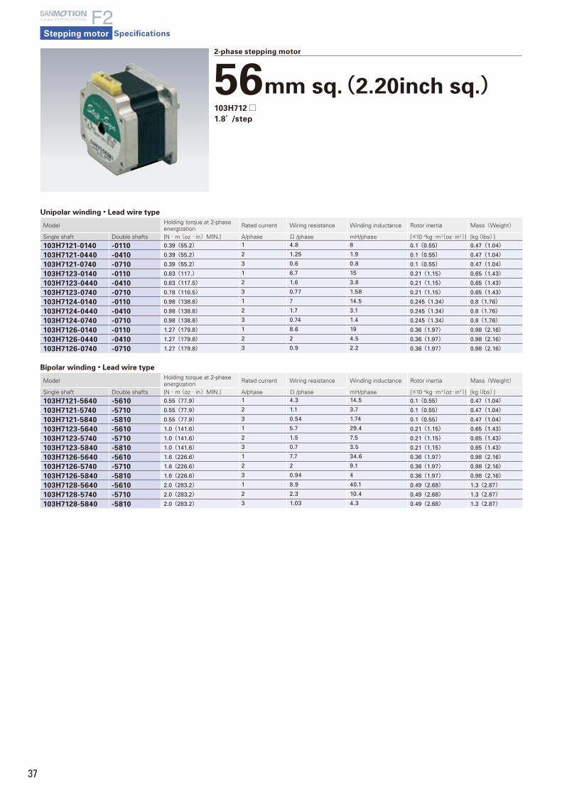
37
Stepping motor
2-phase STEPPING SYSTEMS
Specifications
2-phase stepping motor
56mm sq.(2.20inch sq.)103H712□1.8°/step
Unipolar winding・Lead wire type
Model Holding torque at 2-phase energization Rated current Wiring resistance Winding inductance Rotor inertia Mass(Weight)
Single shaft Double shafts [N・m (oz・in)MIN.] A/phase Ω /phase mH/phase [×10- 4kg・m2(oz・in2)] [kg(Ibs)]
103H7121-0140 -0110 0.39(55.2) 1 4.8 8 0.1(0.55) 0.47(1.04)
103H7121-0440 -0410 0.39(55.2) 2 1.25 1.9 0.1(0.55) 0.47(1.04)
103H7121-0740 -0710 0.39(55.2) 3 0.6 0.8 0.1(0.55) 0.47(1.04)
103H7123-0140 -0110 0.83(117.) 1 6.7 15 0.21(1.15) 0.65(1.43)
103H7123-0440 -0410 0.83(117.5) 2 1.6 3.8 0.21(1.15) 0.65(1.43)
103H7123-0740 -0710 0.78(110.5) 3 0.77 1.58 0.21(1.15) 0.65(1.43)
103H7124-0140 -0110 0.98(138.8) 1 7 14.5 0.245(1.34) 0.8(1.76)
103H7124-0440 -0410 0.98(138.8) 2 1.7 3.1 0.245(1.34) 0.8(1.76)
103H7124-0740 -0710 0.98(138.8) 3 0.74 1.4 0.245(1.34) 0.8(1.76)
103H7126-0140 -0110 1.27(179.8) 1 8.6 19 0.36(1.97) 0.98(2.16)
103H7126-0440 -0410 1.27(179.8) 2 2 4.5 0.36(1.97) 0.98(2.16)
103H7126-0740 -0710 1.27(179.8) 3 0.9 2.2 0.36(1.97) 0.98(2.16)
Bipolar winding・Lead wire type
Model Holding torque at 2-phase energization Rated current Wiring resistance Winding inductance Rotor inertia Mass(Weight)
Single shaft Double shafts [N・m (oz・in)MIN.] A/phase Ω /phase mH/phase [×10- 4kg・m2(oz・in2)] [kg(Ibs)]
103H7121-5640 -5610 0.55(77.9) 1 4.3 14.5 0.1(0.55) 0.47(1.04)
103H7121-5740 -5710 0.55(77.9) 2 1.1 3.7 0.1(0.55) 0.47(1.04)
103H7121-5840 -5810 0.55(77.9) 3 0.54 1.74 0.1(0.55) 0.47(1.04)
103H7123-5640 -5610 1.0(141.6) 1 5.7 29.4 0.21(1.15) 0.65(1.43)
103H7123-5740 -5710 1.0(141.6) 2 1.5 7.5 0.21(1.15) 0.65(1.43)
103H7123-5840 -5810 1.0(141.6) 3 0.7 3.5 0.21(1.15) 0.65(1.43)
103H7126-5640 -5610 1.6(226.6) 1 7.7 34.6 0.36(1.97) 0.98(2.16)
103H7126-5740 -5710 1.6(226.6) 2 2 9.1 0.36(1.97) 0.98(2.16)
103H7126-5840 -5810 1.6(226.6) 3 0.94 4 0.36(1.97) 0.98(2.16)
103H7128-5640 -5610 2.0(283.2) 1 8.9 40.1 0.49(2.68) 1.3(2.87)
103H7128-5740 -5710 2.0(283.2) 2 2.3 10.4 0.49(2.68) 1.3(2.87)
103H7128-5840 -5810 2.0(283.2) 3 1.03 4.3 0.49(2.68) 1.3(2.87)
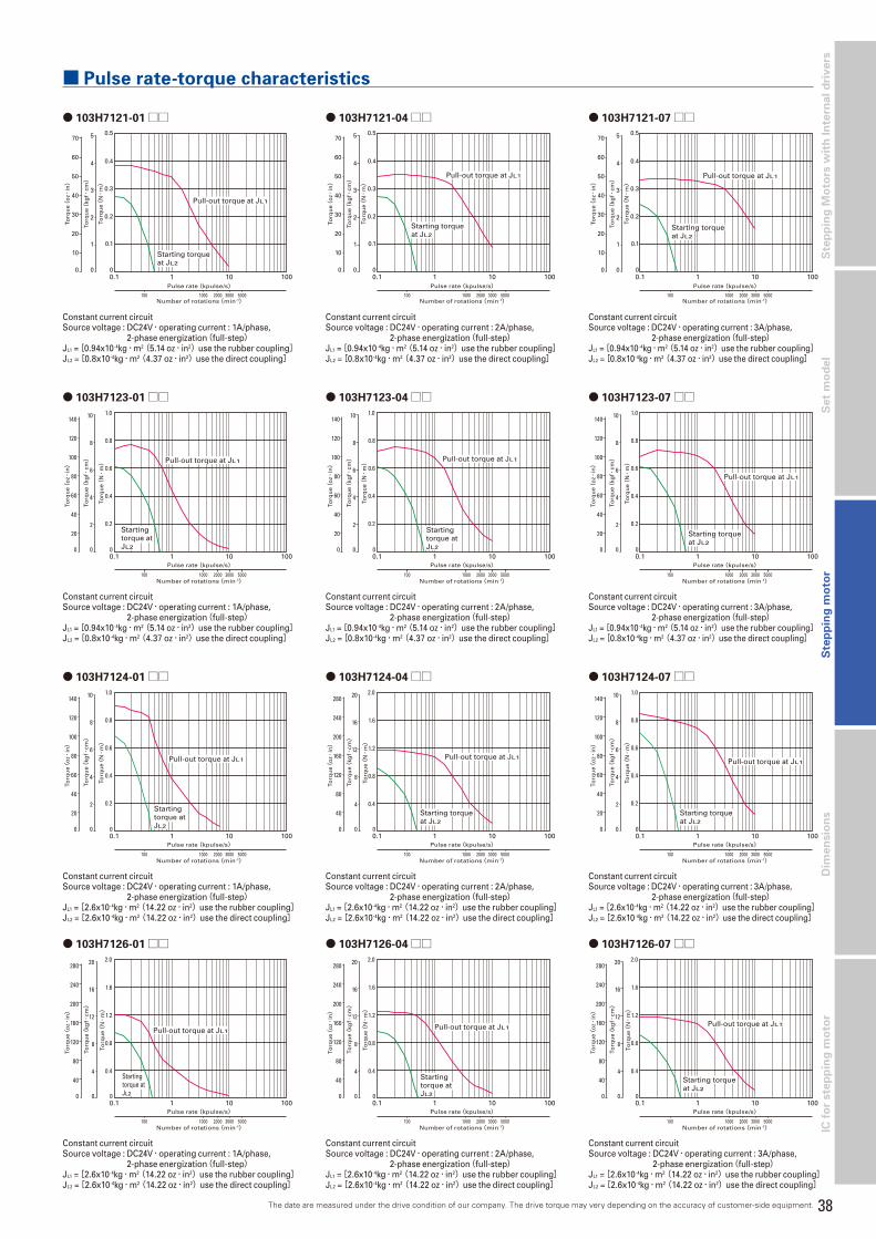
38
Dim
en
sio
ns
Ste
pp
ing
Mo
tors
wit
h I
nte
rna
l d
riv
ers
S
tep
pin
g m
oto
rS
et
mo
de
lIC
fo
r ste
pp
ing
mo
tor
■ Pulse rate-torque characteristics
● 103H7123-04□□
● 103H7121-07□□
● 103H7123-07□□
● 103H7124-01□□ ● 103H7124-04□□
● 103H7121-01□□
● 103H7123-01□□
● 103H7121-04□□
0.1 1 10 100
1000 2000 3000 5000100
Pulse rate(kpulse/s)
Number of rotations(min-1)
70
0
60
50
40
30
20
10
Torq
ue(
kgf・
cm)
Torq
ue(
oz・
in)
Torq
ue(
N・
m)
1
2
3
4
5
0
0.1
0.2
0.3
0.4
0.5
0
Pull-out torque at JL1
Starting torqueat JL2
0.1 1 10 100
1000 2000 3000 5000100
Startingtorque atJL2
Pulse rate(kpulse/s)
Number of rotations(min-1)
Pull-out torque at JL1
140
0
120
100
80
60
40
20
10
8
6
4
2
0 0
0.2
0.4
0.6
0.8
1.0
Torq
ue(
kgf・
cm)
Torq
ue(
oz・
in)
Torq
ue(
N・
m)
0.1 1 10 100
1000 2000 3000 5000100
Pulse rate(kpulse/s)
Number of rotations(min-1)
70
0
60
50
40
30
20
10
Torq
ue(
kgf・
cm)
Torq
ue(
oz・
in)
Torq
ue(
N・
m)
1
2
3
4
5
0
0.1
0.2
0.3
0.4
0.5
0
Pull-out torque at JL1
Starting torqueat JL2
0.1 1 10 100
1000 2000 3000 5000100
Pulse rate(kpulse/s)
Number of rotations(min-1)
Starting torqueat JL2
Pull-out torque at JL1
140
0
120
100
80
60
40
20
10
8
6
4
2
0 0
0.2
0.4
0.6
0.8
1.0
Torq
ue(
kgf・
cm)
Torq
ue(
oz・
in)
Torq
ue(
N・
m)
0.1 1 10 100
1000 2000 3000 5000100
Startingtorque atJL2
Pulse rate(kpulse/s)
Number of rotations(min-1)
Pull-out torque at JL1
140
0
120
100
80
60
40
20
10
8
6
4
2
0 0
0.2
0.4
0.6
0.8
1.0
Torq
ue(
kgf・
cm)
Torq
ue(
oz・
in)
Torq
ue(
N・
m)
0.1 1 10 100
1000 2000 3000 5000100
Pulse rate(kpulse/s)
Number of rotations(min-1)
Starting torqueat JL2
Pull-out torque at JL1
280
0
240
200
160
120
80
40
20
16
12
8
4
0 0
0.4
0.8
1.2
1.6
2.0
Torq
ue(
kgf・
cm)
Torq
ue(
oz・
in)
Torq
ue(
N・
m)
● 103H7124-07□□
0.1 1 10 100
1000 2000 3000 5000100
Pulse rate(kpulse/s)
Number of rotations(min-1)
Starting torqueat JL2
Pull-out torque at JL1
140
0
120
100
80
60
40
20
10
8
6
4
2
0 0
0.2
0.4
0.6
0.8
1.0
Torq
ue(
kgf・
cm)
Torq
ue(
oz・
in)
Torq
ue(
N・
m)
Constant current circuitSource voltage : DC24V・operating current : 1A/phase,
2-phase energization(full-step)JL1 = [0.94x10⁻⁴kg・m2(5.14 oz・in2)use the rubber coupling]JL2 = [0.8x10⁻⁴kg・m2(4.37 oz・in2)use the direct coupling]
Constant current circuitSource voltage : DC24V・operating current : 1A/phase,
2-phase energization(full-step)JL1 = [0.94x10⁻⁴kg・m2(5.14 oz・in2)use the rubber coupling]JL2 = [0.8x10⁻⁴kg・m2(4.37 oz・in2)use the direct coupling]
Constant current circuitSource voltage : DC24V・operating current : 2A/phase,
2-phase energization(full-step)JL1 = [0.94x10⁻⁴kg・m2(5.14 oz・in2)use the rubber coupling]JL2 = [0.8x10⁻⁴kg・m2(4.37 oz・in2)use the direct coupling]
Constant current circuitSource voltage : DC24V・operating current : 2A/phase,
2-phase energization(full-step)JL1 = [0.94x10⁻⁴kg・m2(5.14 oz・in2)use the rubber coupling]JL2 = [0.8x10⁻⁴kg・m2(4.37 oz・in2)use the direct coupling]
Constant current circuitSource voltage : DC24V・operating current : 3A/phase, 2-phase energization(full-step)JL1 = [0.94x10⁻⁴kg・m2(5.14 oz・in2)use the rubber coupling]JL2 = [0.8x10⁻⁴kg・m2(4.37 oz・in2)use the direct coupling]
Constant current circuitSource voltage : DC24V・operating current : 3A/phase, 2-phase energization(full-step)JL1 = [0.94x10⁻⁴kg・m2(5.14 oz・in2)use the rubber coupling]JL2 = [0.8x10⁻⁴kg・m2(4.37 oz・in2)use the direct coupling]
Constant current circuitSource voltage : DC24V・operating current : 1A/phase,
2-phase energization(full-step)JL1 = [2.6x10⁻⁴kg・m2(14.22 oz・in2)use the rubber coupling]JL2 = [2.6x10⁻⁴kg・m2(14.22 oz・in2)use the direct coupling]
Constant current circuitSource voltage : DC24V・operating current : 2A/phase,
2-phase energization(full-step)JL1 = [2.6x10⁻⁴kg・m2(14.22 oz・in2)use the rubber coupling]JL2 = [2.6x10⁻⁴kg・m2(14.22 oz・in2)use the direct coupling]
Constant current circuitSource voltage : DC24V・operating current : 3A/phase, 2-phase energization(full-step)JL1 = [2.6x10⁻⁴kg・m2(14.22 oz・in2)use the rubber coupling]JL2 = [2.6x10⁻⁴kg・m2(14.22 oz・in2)use the direct coupling]
The date are measured under the drive condition of our company. The drive torque may very depending on the accuracy of customer-side equipment.
● 103H7126-04□□ ● 103H7126-07□□
0.1 1 10 100
1000 2000 3000 5000100
Startingtorque atJL2
Pulse rate(kpulse/s)
Number of rotations(min-1)
Pull-out torque at JL1
280
0
240
200
160
120
80
40
20
16
12
8
4
0 0
0.4
0.8
1.2
1.6
2.0
Torq
ue(
kgf・
cm)
Torq
ue(
oz・
in)
Torq
ue(
N・
m)
0.1 1 10 100
1000 2000 3000 5000100
Pulse rate(kpulse/s)
Number of rotations(min-1)
Starting torqueat JL2
Pull-out torque at JL1
280
0
240
200
160
120
80
40
20
16
12
8
4
0 0
0.4
0.8
1.2
1.6
2.0
Torq
ue(
kgf・
cm)
Torq
ue(
oz・
in)
Torq
ue(
N・
m)
● 103H7126-01□□
0.1 1 10 100
1000 2000 3000 5000100
Pulse rate(kpulse/s)
Number of rotations(min-1)
Pull-out torque at JL1
Startingtorque atJL2
280
0
240
200
160
120
80
40
20
16
12
8
4
0 0
0.4
0.8
1.2
1.6
2.0
Torq
ue(
kgf・
cm)
Torq
ue(
oz・
in)
Torq
ue(
N・
m)
Constant current circuitSource voltage : DC24V・operating current : 1A/phase,
2-phase energization(full-step)JL1 = [2.6x10⁻⁴kg・m2(14.22 oz・in2)use the rubber coupling]JL2 = [2.6x10⁻⁴kg・m2(14.22 oz・in2)use the direct coupling]
Constant current circuitSource voltage : DC24V・operating current : 2A/phase,
2-phase energization(full-step)JL1 = [2.6x10⁻⁴kg・m2(14.22 oz・in2)use the rubber coupling]JL2 = [2.6x10⁻⁴kg・m2(14.22 oz・in2)use the direct coupling]
Constant current circuitSource voltage : DC24V・operating current : 3A/phase,
2-phase energization(full-step)JL1 = [2.6x10⁻⁴kg・m2(14.22 oz・in2)use the rubber coupling]JL2 = [2.6x10⁻⁴kg・m2(14.22 oz・in2)use the direct coupling]
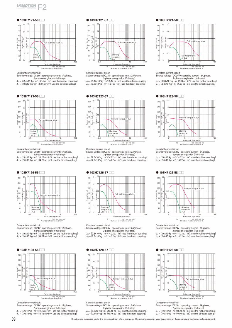
39
● 103H7121-58□□● 103H7121-56□□
0.1 1 10 100
1000 2000 3000 5000100
Pulse rate(kpulse/s)
Number of rotations(min-1)
Starting torqueat JL2
Pull-out torque at JL1
140
0
120
100
80
60
40
20
10
8
6
4
2
0 0
0.2
0.4
0.6
0.8
1.0
Torq
ue(
kgf・
cm)
Torq
ue(
oz・
in)
Torq
ue(
N・
m)
0.1 1 10 100
1000 2000 3000 5000100
Pulse rate(kpulse/s)
Number of rotations(min-1)
Pull-out torque at JL1
Startingtorque atJL2
140
0
120
100
80
60
40
20
10
8
6
4
2
0 0
0.2
0.4
0.6
0.8
1.0To
rqu
e(kg
f・cm)
Torq
ue(
oz・
in)
Torq
ue(
N・
m)
● 103H7121-57□□
0.1 1 10 100
1000 2000 3000 5000100
Startingtorque atJL2
Pulse rate(kpulse/s)
Number of rotations(min-1)
Pull-out torque at JL1
140
0
120
100
80
60
40
20
10
8
6
4
2
0 0
0.2
0.4
0.6
0.8
1.0
Torq
ue(
kgf・
cm)
Torq
ue(
oz・
in)
Torq
ue(
N・
m)
Constant current circuitSource voltage : DC24V・operating current : 1A/phase,
2-phase energization(full-step)JL1 = [0.94x10⁻⁴kg・m2(5.14 oz・in2)use the rubber coupling]JL2 = [0.8x10⁻⁴kg・m2(4.37 oz・in2)use the direct coupling]
Constant current circuitSource voltage : DC24V・operating current : 2A/phase,
2-phase energization(full-step)JL1 = [0.94x10⁻⁴kg・m2(5.14 oz・in2)use the rubber coupling]JL2 = [0.8x10⁻⁴kg・m2(4.37 oz・in2)use the direct coupling]
Constant current circuitSource voltage : DC24V・operating current : 3A/phase,
2-phase energization(full-step)JL1 = [0.94x10⁻⁴kg・m2(5.14 oz・in2)use the rubber coupling]JL2 = [0.8x10⁻⁴kg・m2(4.37 oz・in2)use the direct coupling]
● 103H7123-58□□
0.1 1 10 100
1000 2000 3000 5000100
Startingtorque atJL2
Pulse rate(kpulse/s)
Number of rotations(min-1)
Pull-out torque at JL1
280
0
240
200
160
120
80
40
20
16
12
8
4
0 0
0.4
0.8
1.2
1.6
2.0
Torq
ue(
kgf・
cm)
Torq
ue(
oz・
in)
Torq
ue(
N・
m)
● 103H7123-56□□ ● 103H7123-57□□
0.1 1 10 100
1000 2000 3000 5000100
Pulse rate(kpulse/s)
Number of rotations(min-1)
Pull-out torque at JL1
Startingtorque atJL2
280
0
240
200
160
120
80
40
20
16
12
8
4
0 0
0.4
0.8
1.2
1.6
2.0
Torq
ue(
kgf・
cm)
Torq
ue(
oz・
in)
Torq
ue(
N・
m)
0.1 1 10 100
1000 2000 3000 5000100
Startingtorque atJL2
Pulse rate(kpulse/s)
Number of rotations(min-1)
Pull-out torque at JL1
280
0
240
200
160
120
80
40
20
16
12
8
4
0 0
0.4
0.8
1.2
1.6
2.0
Torq
ue(
kgf・
cm)
Torq
ue(
oz・
in)
Torq
ue(
N・
m)
Constant current circuitSource voltage : DC24V・operating current : 1A/phase,
2-phase energization(full-step)JL1 = [2.6x10⁻⁴kg・m2(14.22 oz・in2)use the rubber coupling]JL2 = [2.6x10⁻⁴kg・m2(14.22 oz・in2)use the direct coupling]
Constant current circuitSource voltage : DC24V・operating current : 2A/phase,
2-phase energization(full-step)JL1 = [2.6x10⁻⁴kg・m2(14.22 oz・in2)use the rubber coupling]JL2 = [2.6x10⁻⁴kg・m2(14.22 oz・in2)use the direct coupling]
Constant current circuitSource voltage : DC24V・operating current : 3A/phase, 2-phase energization(full-step)JL1 = [2.6x10⁻⁴kg・m2(14.22 oz・in2)use the rubber coupling]JL2 = [2.6x10⁻⁴kg・m2(14.22 oz・in2)use the direct coupling]
● 103H7126-58□□● 103H7126-56□□ ● 103H7126-57□□
0.1 1 10 100
1000 2000 3000 5000100
Startingtorque atJL2
Pulse rate(kpulse/s)
Number of rotations(min-1)
Pull-out torque at JL1
280
0
240
200
160
120
80
40
20
16
12
8
4
0 0
0.4
0.8
1.2
1.6
2.0
Torq
ue(
kgf・
cm)
Torq
ue(
oz・
in)
Torq
ue(
N・
m)
0.1 1 10 100
1000 2000 3000 5000100
Startingtorque atJL2
Pulse rate(kpulse/s)
Number of rotations(min-1)
Pull-out torque at JL1
280
0
240
200
160
120
80
40
20
16
12
8
4
0 0
0.4
0.8
1.2
1.6
2.0
Torq
ue(
kgf・
cm)
Torq
ue(
oz・
in)
Torq
ue(
N・
m)
0.1 1 10 100
1000 2000 3000 5000100
Startingtorque atJL2
Pulse rate(kpulse/s)
Number of rotations(min-1)
Pull-out torque at JL1
280
0
240
200
160
120
80
40
20
16
12
8
4
0 0
0.4
0.8
1.2
1.6
2.0
Torq
ue(
kgf・
cm)
Torq
ue(
oz・
in)
Torq
ue(
N・
m)
Constant current circuitSource voltage : DC24V・operating current : 1A/phase,
2-phase energization(full-step)JL1 = [2.6x10⁻⁴kg・m2(14.22 oz・in2)use the rubber coupling]JL2 = [2.6x10⁻⁴kg・m2(14.22 oz・in2)use the direct coupling]
Constant current circuitSource voltage : DC24V・operating current : 2A/phase,
2-phase energization(full-step)JL1 = [2.6x10⁻⁴kg・m2(14.22 oz・in2)use the rubber coupling]JL2 = [2.6x10⁻⁴kg・m2(14.22 oz・in2)use the direct coupling]
Constant current circuitSource voltage : DC24V・operating current : 3A/phase, 2-phase energization(full-step)JL1 = [2.6x10⁻⁴kg・m2(14.22 oz・in2)use the rubber coupling]JL2 = [2.6x10⁻⁴kg・m2(14.22 oz・in2)use the direct coupling]
● 103H7128-56□□ ● 103H7128-57□□ ● 103H7128-58□□
0.1 1 10 100
1000 2000 3000 5000100
Pulse rate(kpulse/s)
Number of rotations(min-1)
Torq
ue(
kgf・
cm)
Torq
ue(
oz・
in)
Torq
ue(
N・
m)
Pull-out torque at JL1
Startingtorque atJL2
700
0
600
500
400
300
200
10010
20
30
40
50
0
1.0
2.0
3.0
4.0
5.0
00.1 1 10 100
1000 2000 3000 5000100
Pulse rate(kpulse/s)
Number of rotations(min-1)
Torq
ue(
kgf・
cm)
Torq
ue(
oz・
in)
Torq
ue(
N・
m)
Pull-out torque at JL1
Startingtorque atJL2
700
0
600
500
400
300
200
10010
20
30
40
50
0
1.0
2.0
3.0
4.0
5.0
00.1 1 10 100
1000 2000 3000 5000100
Pulse rate(kpulse/s)
Number of rotations(min-1)
Torq
ue(
kgf・
cm)
Torq
ue(
oz・
in)
Torq
ue(
N・
m)
Pull-out torque at JL1
Startingtorque atJL2
700
0
600
500
400
300
200
10010
20
30
40
50
0
1.0
2.0
3.0
4.0
5.0
0
Constant current circuitSource voltage : DC24V・operating current : 1A/phase,
2-phase energization(full-step)JL1 = [7.4x10⁻⁴kg・m2(40.46 oz・in2)use the rubber coupling]JL2 = [7.4x10⁻⁴kg・m2(40.46 oz・in2)use the direct coupling]
Constant current circuitSource voltage : DC24V・operating current : 2A/phase,
2-phase energization(full-step)JL1 = [7.4x10⁻⁴kg・m2(40.46 oz・in2)use the rubber coupling]JL2 = [7.4x10⁻⁴kg・m2(40.46 oz・in2)use the direct coupling]
Constant current circuitSource voltage : DC24V・operating current : 3A/phase, 2-phase energization(full-step)JL1 = [7.4x10⁻⁴kg・m2(40.46 oz・in2)use the rubber coupling]JL2 = [7.4x10⁻⁴kg・m2(40.46 oz・in2)use the direct coupling]
The date are measured under the drive condition of our company. The drive torque may very depending on the accuracy of customer-side equipment.The date are measured under the drive condition of our company. The drive torque may very depending on the accuracy of customer-side equipment.
2-phase STEPPING SYSTEMS

40
Dim
en
sio
ns
Ste
pp
ing
Mo
tors
wit
h I
nte
rna
l d
riv
ers
S
tep
pin
g m
oto
rS
et
mo
de
lIC
fo
r ste
pp
ing
mo
tor
2-phase stepping motor
60mm sq.(2.36inch sq.)SH160□0.9°/step
0.1 1 10 100Pulse rate(kpulse/s)
Number of rotations(min-1)
280
0
240
200
160
120
80
40
Torq
ue(
kgf・
cm)
Torq
ue(
oz・
in)
Torq
ue(
N・
m)
4
8
12
16
20
0
0.4
0.8
1.2
1.6
2.0
0
50 100 500 1000 2000
Pull-out torque at JL1
0.1 1 10 100Pulse rate(kpulse/s)
Number of rotations(min-1)
280
0
240
200
160
120
80
40
Torq
ue(
kgf・
cm)
Torq
ue(
oz・
in)
Torq
ue(
N・
m)
4
8
12
16
20
0
0.4
0.8
1.2
1.6
2.0
0
50 100 500 1000 2000
Pull-out torque at JL1
■ Pulse rate-torque characteristics
0.1 1 10 100Pulse rate(kpulse/s)
Number of rotations(min-1)
140
0
120
100
80
60
40
20
Torq
ue(
kgf・
cm)
Torq
ue(
oz・
in)
Torq
ue(
N・
m)
2
4
6
8
10
0
0.2
0.4
0.6
0.8
1.0
0
50 100 500 1000 2000
Pull-out torque at JL1
● SH1601-04□□ ● SH1602-04□□ ● SH1603-04□□
Unipolar winding・Lead wire type
Model Holding torque at 2-phase energization Rated current Wiring resistance Winding inductance Rotor inertia Mass(Weight)
Single shaft Double shafts [N・m (oz・in)MIN.] A/phase Ω /phase mH/phase [×10- 4kg・m2(oz・in2)] [kg(Ibs)]
SH1601-0440 -0410 0.57 (80.71) 2 1.35 2 0.24(1.312) 0.55(1.21)
SH1602-0440 -0410 1.1 (155.77) 2 1.8 3.5 0.4(2.187) 0.8(1.76)
SH1603-0440 -0410 1.7 (240.74) 2 2.3 4.5 0.75(4.101) 1.2(2.64)
Constant current circuitSource voltage : DC24V・operating current : 2A/phase, 2-phase energization(full-step)JL1 = [0.94x10⁻⁴kg・m2(5.14 oz・in2)use the rubber coupling]
Constant current circuitSource voltage : DC24V・operating current : 2A/phase, 2-phase energization(full-step)JL1 = [2.6x10⁻⁴kg・m2(14.22 oz・in2)use the rubber coupling]
Constant current circuitSource voltage : DC24V・operating current : 2A/phase, 2-phase energization(full-step)JL1 = [7.4x10⁻⁴kg・m2(40.46 oz・in2)use the rubber coupling]
The date are measured under the drive condition of our company. The drive torque may very depending on the accuracy of customer-side equipment.
0.1 1 10 100Pulse rate(kpulse/s)
Number of rotations(min-1)
280
0
240
200
160
120
80
40
Torq
ue(
kgf・
cm)
Torq
ue(
oz・
in)
Torq
ue(
N・
m)
4
8
12
16
20
0
0.4
0.8
1.2
1.6
2.0
0
50 100 500 1000 2000
Pull-out torque at JL1
0.1 1 10 100Pulse rate(kpulse/s)
Number of rotations(min-1)
560
0
480
400
320
240
160
80
Torq
ue(
kgf・
cm)
Torq
ue(
oz・
in)
Torq
ue(
N・
m)
8
16
24
32
40
0
0.8
1.6
2.4
3.2
4.0
0
50 100 500 1000 2000
Pull-out torque at JL1
■ Pulse rate-torque characteristics
0.1 1 10 100Pulse rate(kpulse/s)
Number of rotations(min-1)
140
0
120
100
80
60
40
20
Torq
ue(
kgf・
cm)
Torq
ue(
oz・
in)
Torq
ue(
N・
m)
2
4
6
8
10
0
0.2
0.4
0.6
0.8
1.0
0
50 100 500 1000 2000
Pull-out torque at JL1
● SH1601-52□□ ● SH1602-52□□ ● SH1603-52□□
Bipolar winding・Lead wire type
Model Holding torque at 2-phase energization Rated current Wiring resistance Winding inductance Rotor inertia Mass(Weight)
Single shaft Double shafts [N・m (oz・in)MIN.] A/phase Ω /phase mH/phase [×10- 4kg・m2(oz・in2)] [kg(Ibs)]
SH1601-5240 -5210 0.69(97.7) 2 1.2 3.5 0.24(1.31) 0.55(1.21)
SH1602-5240 -5210 1.28(181.2) 2 1.65 6.1 0.4(2.19) 0.8(1.76)
SH1603-5240 -5210 2.15(304.4) 2 2.3 8.8 0.75(4.10) 1.2(2.65)
Constant current circuitSource voltage : DC24V・operating current : 2A/phase, 2-phase energization(full-step)JL1 = [0.94x10⁻⁴kg・m2(5.14 oz・in2)use the rubber coupling]
Constant current circuitSource voltage : DC24V・operating current : 2A/phase, 2-phase energization(full-step)JL2 = [2.6x10⁻⁴kg・m2(14.22 oz・in2)use the rubber coupling]
Constant current circuitSource voltage : DC24V・operating current : 2A/phase, 2-phase energization(full-step)JL3 = [7.4x10⁻⁴kg・m2(40.46 oz・in2)use the rubber coupling]
The date are measured under the drive condition of our company. The drive torque may very depending on the accuracy of customer-side equipment.

41
Stepping motor
2-phase STEPPING SYSTEMS
Specifications
2-phase stepping motor
60mm sq.(2.36inch sq.)103H782□1.8°/step
Unipolar winding・Connector type
Model Holding torque at 2-phase energization Rated current Wiring resistance Winding inductance Rotor inertia Mass(Weight)
Single shaft Double shafts [N・m (oz・in)MIN.] A/phase Ω /phase mH/phase [×10- 4kg・m2(oz・in2)] [kg(Ibs)]
103H7821-0140 -0110 0.78(110.5) 1 5.7 8.3 0.275(1.50) 0.6(1.32)
103H7821-0440 -0410 0.78(110.5) 2 1.5 2 0.275(1.50) 0.6(1.32)
103H7821-0740 -0710 0.78(110.5) 3 0.68 0.8 0.275(1.50) 0.6(1.32)
103H7822-0140 -0110 1.17(165.7) 1 6.9 14 0.4(2.19) 0.77(1.70)
103H7822-0440 -0410 1.17(165.7) 2 1.8 3.6 0.4(2.19) 0.77(1.70)
103H7822-0740 -0710 1.17(165.7) 3 0.8 1.38 0.4(2.19) 0.77(1.70)
103H7823-0140 -0110 2.1(297.4) 1 10 21.7 0.84(4.59) 1.34(2.95)
103H7823-0440 -0410 2.1(297.4) 2 2.7 5.6 0.84(4.59) 1.34(2.95)
103H7823-0740 -0710 2.1(297.4) 3 1.25 2.4 0.84(4.59) 1.34(2.95)
Bipolar winding・Connector type
Model Holding torque at 2-phase energization Rated current Wiring resistance Winding inductance Rotor inertia Mass(Weight)
Single shaft Double shafts [N・m (oz・in)MIN.] A/phase Ω /phase mH/phase [×10- 4kg・m2(oz・in2)] [kg(Ibs)]
103H7821-1740 -1710 0.88(124.6) 4 0.35 0.8 0.275(1.50) 0.6(1.32)
103H7821-5740 -5710 0.88(124.6) 2 1.27 3.3 0.275(1.50) 0.6(1.32)
103H7822-1740 -1710 1.37(194.0) 4 0.43 1.38 0.4(2.19) 0.77(1.70)
103H7822-5740 -5710 1.37(194.0) 2 1.55 5.5 0.4(2.19) 0.77(1.70)
103H7823-1740 -1710 2.7(382.3) 4 0.65 2.4 0.84(4.59) 1.34(2.95)
103H7823-5740 -5710 2.7(382.3) 2 2.4 9.5 0.84(4.59) 1.34(2.95)
● 103H7821-01□□ ● 103H7821-04□□ ● 103H7821-07□□
■ Pulse rate-torque characteristics
0.1 1 10 100
1000 2000 3000 5000100
Startingtorque atJL2
Pulse rate(kpulse/s)
Number of rotations(min-1)
Pull-out torque at JL1
140
0
120
100
80
60
40
20
10
8
6
4
2
0 0
0.2
0.4
0.6
0.8
1.0
Torq
ue(
kgf・
cm)
Torq
ue(
oz・
in)
Torq
ue(
N・
m)
0.1 1 10 100
1000 2000 3000 5000100
Pulse rate(kpulse/s)
Number of rotations(min-1)
Starting torqueat JL2
Pull-out torque at JL1
140
0
120
100
80
60
40
20
10
8
6
4
2
0 0
0.2
0.4
0.6
0.8
1.0
Torq
ue(
kgf・
cm)
Torq
ue(
oz・
in)
Torq
ue(
N・
m)
0.1 1 10 100
1000 2000 3000 5000100
Pulse rate(kpulse/s)
Number of rotations(min-1)
Starting torqueat JL2
Pull-out torque at JL1
140
0
120
100
80
60
40
20
10
8
6
4
2
0 0
0.2
0.4
0.6
0.8
1.0
Torq
ue(
kgf・
cm)
Torq
ue(
oz・
in)
Torq
ue(
N・
m)
Constant current circuitSource voltage : DC24V・operating current : 1A/phase,
2-phase energization(full-step)JL1 = [0.94x10⁻⁴kg・m2(5.14 oz・in2)use the rubber coupling]JL2 = [0.8x10⁻⁴kg・m2(4.37 oz・in2)use the direct coupling]
Constant current circuitSource voltage : DC24V・operating current : 2A/phase,
2-phase energization(full-step)JL1 = [0.94x10⁻⁴kg・m2(5.14 oz・in2)use the rubber coupling]JL2 = [0.8x10⁻⁴kg・m2(4.37 oz・in2)use the direct coupling]
Constant current circuitSource voltage : DC24V・operating current : 3A/phase,
2-phase energization(full-step)JL1 = [0.94x10⁻⁴kg・m2(5.14 oz・in2)use the rubber coupling]JL2 = [0.8x10⁻⁴kg・m2(4.37 oz・in2)use the direct coupling]
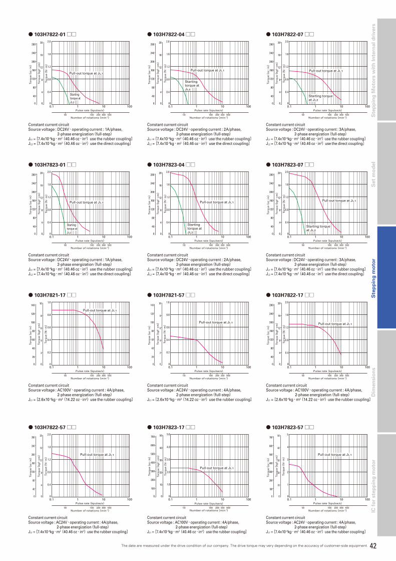
42
Dim
en
sio
ns
Ste
pp
ing
Mo
tors
wit
h I
nte
rna
l d
riv
ers
S
tep
pin
g m
oto
rS
et
mo
de
lIC
fo
r ste
pp
ing
mo
tor
● 103H7822-01□□ ● 103H7822-04□□ ● 103H7822-07□□
● 103H7823-07□□● 103H7823-01□□
● 103H7821-17□□
● 103H7823-04□□
0.1 1 10 100
1000 2000 3000 5000100
Pulse rate(kpulse/s)
Number of rotations(min-1)
Pull-out torque at JL1
Startingtorque atJL2
280
0
240
200
160
120
80
40
20
16
12
8
4
0 0
0.4
0.8
1.2
1.6
2.0To
rqu
e(kg
f・cm)
Torq
ue(
oz・
in)
Torq
ue(
N・
m)
0.1 1 10 100
1000 2000 3000 5000100
Startingtorque atJL2
Pulse rate(kpulse/s)
Number of rotations(min-1)
Pull-out torque at JL1
280
0
240
200
160
120
80
40
20
16
12
8
4
0 0
0.4
0.8
1.2
1.6
2.0
Torq
ue(
kgf・
cm)
Torq
ue(
oz・
in)
Torq
ue(
N・
m)
0.1 1 10 100
1000 2000 3000 5000100
Pulse rate(kpulse/s)
Number of rotations(min-1)
Starting torqueat JL2
Pull-out torque at JL1
280
0
240
200
160
120
80
40
20
16
12
8
4
0 0
0.4
0.8
1.2
1.6
2.0
Torq
ue(
kgf・
cm)
Torq
ue(
oz・
in)
Torq
ue(
N・
m)
0.1 1 10 100
1000 2000 3000 5000100
Pulse rate(kpulse/s)
Number of rotations(min-1)
Pull-out torque at JL1
Startingtorque atJL2
280
0
240
200
160
120
80
40
20
16
12
8
4
0 0
0.4
0.8
1.2
1.6
2.0
Torq
ue(
kgf・
cm)
Torq
ue(
oz・
in)
Torq
ue(
N・
m)
0.1 1 10 100
1000 2000 3000 5000100
Pulse rate(kpulse/s)
Number of rotations(min-1)
Pull-out torque at JL1
140
0
120
100
80
60
40
20
10
8
6
4
2
0 0
0.2
0.4
0.6
0.8
1.0
Torq
ue(
kgf・
cm)
Torq
ue(
oz・
in)
Torq
ue(
N・
m)
0.1 1 10 100
1000 2000 3000 5000100
Startingtorque atJL2
Pulse rate(kpulse/s)
Number of rotations(min-1)
Pull-out torque at JL1
280
0
240
200
160
120
80
40
20
16
12
8
4
0 0
0.4
0.8
1.2
1.6
2.0
Torq
ue(
kgf・
cm)
Torq
ue(
oz・
in)
Torq
ue(
N・
m)
0.1 1 10 100
1000 2000 3000 5000100
Pulse rate(kpulse/s)
Number of rotations(min-1)
Starting torqueat JL2
Pull-out torque at JL1
280
0
240
200
160
120
80
40
20
16
12
8
4
0 0
0.4
0.8
1.2
1.6
2.0
Torq
ue(
kgf・
cm)
Torq
ue(
oz・
in)
Torq
ue(
N・
m)
Constant current circuitSource voltage : DC24V・operating current : 1A/phase,
2-phase energization(full-step)JL1 = [7.4x10⁻⁴kg・m2(40.46 oz・in2)use the rubber coupling]JL2 = [7.4x10⁻⁴kg・m2(40.46 oz・in2)use the direct coupling]
Constant current circuitSource voltage : DC24V・operating current : 2A/phase,
2-phase energization(full-step)JL1 = [7.4x10⁻⁴kg・m2(40.46 oz・in2)use the rubber coupling]JL2 = [7.4x10⁻⁴kg・m2(40.46 oz・in2)use the direct coupling]
Constant current circuitSource voltage : DC24V・operating current : 3A/phase, 2-phase energization(full-step)JL1 = [7.4x10⁻⁴kg・m2(40.46 oz・in2)use the rubber coupling]JL2 = [7.4x10⁻⁴kg・m2(40.46 oz・in2)use the direct coupling]
Constant current circuitSource voltage : AC100V・operating current : 4A/phase,
2-phase energization(full-step)JL1 = [2.6x10⁻⁴kg・m2(14.22 oz・in2)use the rubber coupling]
● 103H7823-17□□
0.1 1 10 100
1000 2000 3000 5000100
Pulse rate(kpulse/s)
Number of rotations(min-1)
Torq
ue(
kgf・
cm)
Torq
ue(
oz・
in)
Torq
ue(
N・
m)
Pull-out torque at JL1
700
0
600
500
400
300
200
10010
20
30
40
50
0
1.0
2.0
3.0
4.0
5.0
0
Constant current circuitSource voltage : AC100V・operating current : 4A/phase, 2-phase energization(full-step)JL1 = [7.4x10⁻⁴kg・m2(40.46 oz・in2)use the rubber coupling]
● 103H7822-17□□
0.1 1 10 100
1000 2000 3000 5000100
Pulse rate(kpulse/s)
Number of rotations(min-1)
Pull-out torque at JL1
280
0
240
200
160
120
80
40
20
16
12
8
4
0 0
0.4
0.8
1.2
1.6
2.0
Torq
ue(
kgf・
cm)
Torq
ue(
oz・
in)
Torq
ue(
N・
m)
Constant current circuitSource voltage : AC100V・operating current : 4A/phase,
2-phase energization(full-step)JL1 = [2.6x10⁻⁴kg・m2(14.22 oz・in2)use the rubber coupling]
The date are measured under the drive condition of our company. The drive torque may very depending on the accuracy of customer-side equipment.
● 103H7821-57□□
0.1 1 10 100
1000 2000 3000 5000100
Pulse rate(kpulse/s)
Number of rotations(min-1)
Pull-out torque at JL1
140
0
120
100
80
60
40
20
10
8
6
4
2
0 0
0.2
0.4
0.6
0.8
1.0
Torq
ue(
kgf・
cm)
Torq
ue(
oz・
in)
Torq
ue(
N・
m)
Constant current circuitSource voltage : AC24V・operating current : 4A/phase,
2-phase energization(full-step)JL1 = [2.6x10⁻⁴kg・m2(14.22 oz・in2)use the rubber coupling]
● 103H7822-57□□
0.1 1 10 100
1000 2000 3000 5000100
Pulse rate(kpulse/s)
Number of rotations(min-1)
Pull-out torque at JL1
280
0
240
200
160
120
80
40
20
16
12
8
4
0 0
0.4
0.8
1.2
1.8
2.0
Torq
ue(
kgf・
cm)
Torq
ue(
oz・
in)
Torq
ue(
N・
m)
Constant current circuitSource voltage : AC24V・operating current : 4A/phase, 2-phase energization(full-step)JL1 = [7.4x10⁻⁴kg・m2(40.46 oz・in2)use the rubber coupling]
● 103H7823-57□□
0.1 1 10 100
1000 2000 3000 5000100
Pulse rate(kpulse/s)
Number of rotations(min-1)
Pull-out torque at JL1
700
0
600
500
400
300
200
100
50
40
30
20
10
0 0
1
2
3
4
5
Torq
ue(
kgf・
cm)
Torq
ue(
oz・
in)
Torq
ue(
N・
m)
Constant current circuitSource voltage : AC24V・operating current : 4A/phase, 2-phase energization(full-step)JL1 = [7.4x10⁻⁴kg・m2(40.46 oz・in2)use the rubber coupling]

43
Stepping motor
2-phase STEPPING SYSTEMS
Specifications
2-phase stepping motor
86mm sq.(3.39inch sq.)SH286□ /SM286□1.8°/step
Unipolar winding・Lead wire type
Model Holding torque at 2-phase energization Rated current Wiring resistance Winding inductance Rotor inertia Mass(Weight)
Single shaft Double shafts [N・m (oz・in)MIN.] A/phase Ω /phase mH/phase [×10- 4kg・m2(oz・in2)] [kg(Ibs)]
SH2861-0441 -0411 2.5(354) 2 2.3 8.0 1.48(8.09) 1.75(3.92)
SH2861-0941 -0911 2.5(354) 4 0.6 2.0 1.48(8.09) 1.75(3.92)
SH2862-0441 -0411 4.7(665.6) 2 3.2 13.0 3(16.4) 2.9(6.5)
SH2862-0941 -0911 4.7(665.6) 4 0.85 3.4 3(16.4) 2.9(6.5)
SH2863-0441 -0411 6.7(948.8) 2 4.0 17.0 4.5(24.6) 4.0(8.96)
SH2863-0941 -0911 6.7(948.8) 4 0.9 4.2 4.5(24.6) 4.0(8.96)
Bipolar winding・Lead wire type CE・UL model
Model Holding torque at 2-phase energization Rated current Wiring resistance Winding inductance Rotor inertia Mass(Weight)
Single shaft Double shafts [N・m (oz・in)MIN.] A/phase Ω /phase mH/phase [×10- 4kg・m2(oz・in2)] [kg(Ibs)]
SM2861-5051 -5021 3.3(467.3) 2 2.2 15 1.48(8.09) 1.75(3.92)
SM2861-5151 -5121 3.3(467.3) 4 0.56 3.7 1.48(8.09) 1.75(3.92)
SM2861-5251 -5221 3.3(467.3) 6 0.29 1.7 1.48(8.09) 1.75(3.92)
SM2862-5051 -5021 6.4(906.3) 2 3.2 25 3.0(16.4) 2.9(6.5)
SM2862-5151 -5121 6.4(906.3) 4 0.83 6.4 3.0(16.4) 2.9(6.5)
SM2862-5251 -5221 6.4(906.3) 6 0.36 2.8 3.0(16.4) 2.9(6.5)
SM2863-5051 -5021 9(1274.4) 2 4.0 32 4.5(24.6) 4.0(8.96)
SM2863-5151 -5121 9(1274.4) 4 1.0 7.9 4.5(24.6) 4.0(8.96)
SM2863-5251 -5221 9(1274.4) 6 0.46 3.8 4.5(24.6) 4.0(8.96)
Bipolar winding・Terminal block type
Model Holding torque at 2-phase energization Rated current Wiring resistance Winding inductance Rotor inertia Mass(Weight)
Single shaft [N・m (oz・in)MIN.] A/phase Ω /phase mH/phase [×10- 4kg・m2(oz・in2)] [kg(Ibs)]
SM2861-5066 3.3(467.3) 2 2.03 15 1.48(8.09) 1.9(4.19)
SM2861-5166 3.3(467.3) 4 0.52 3.7 1.48(8.09) 1.9(4.19)
SM2861-5266 3.3(467.3) 6 0.27 1.7 1.48(8.09) 1.9(4.19)
SM2862-5066 6.4(906.3) 2 3.08 25 3.0(16.4) 3.05(6.72)
SM2862-5166 6.4(906.3) 4 0.79 6.4 3.0(16.4) 3.05(6.72)
SM2862-5266 6.4(906.3) 6 0.33 2.8 3.0(16.4) 3.05(6.72)
SM2863-5066 9(1274.4) 2 3.83 32 4.5(24.6) 4.15(9.15)
SM2863-5166 9(1274.4) 4 0.96 7.9 4.5(24.6) 4.15(9.15)
SM2863-5266 9(1274.4) 6 0.48 3.8 4.5(24.6) 4.15(9.15)
Bipolar winding・Lead wire type
Model Holding torque at 2-phase energization Rated current Wiring resistance Winding inductance Rotor inertia Mass(Weight)
Single shaft Double shafts [N・m (oz・in)MIN.] A/phase Ω /phase mH/phase [×10- 4kg・m2(oz・in2)] [kg(Ibs)]
SH2861-5041 -5011 3.3(467.3) 2 2.2 15 1.48(8.09) 1.75(3.92)
SH2861-5141 -5111 3.3(467.3) 4 0.56 3.7 1.48(8.09) 1.75(3.92)
SH2861-5241 -5211 3.3(467.3) 6 0.29 1.7 1.48(8.09) 1.75(3.92)
SH2862-5041 -5011 6.4(906.3) 2 3.2 25 3.0(16.4) 2.9(6.5)
SH2862-5141 -5111 6.4(906.3) 4 0.83 6.4 3.0(16.4) 2.9(6.5)
SH2862-5241 -5211 6.4(906.3) 6 0.36 2.8 3.0(16.4) 2.9(6.5)
SH2863-5041 -5011 9(1274.4) 2 4.0 32 4.5(24.6) 4.0(8.96)
SH2863-5141 -5111 9(1274.4) 4 1.0 7.9 4.5(24.6) 4.0(8.96)
SH2863-5241 -5211 9(1274.4) 6 0.46 3.8 4.5(24.6) 4.0(8.96)
Unipolar winding・Lead wire type CE・UL model
Model Holding torque at 2-phase energization Rated current Wiring resistance Winding inductance Rotor inertia Mass(Weight)
Single shaft Double shafts [N・m (oz・in)MIN.] A/phase Ω /phase mH/phase [×10- 4kg・m2(oz・in2)] [kg(Ibs)]
SM2861-0451 -0421 2.5(354) 2 2.3 8.0 1.48(8.09) 1.75(3.92)
SM2861-0951 -0921 2.5(354) 4 0.6 2.0 1.48(8.09) 1.75(3.92)
SM2862-0451 -0421 4.8(679.7) 2 3.2 13.0 3(16.4) 2.9(6.5)
SM2862-0951 -0921 4.8(679.7) 4 0.85 3.4 3(16.4) 2.9(6.5)
SM2863-0451 -0421 6.6(934.6) 2 4.0 17 4.5(24.6) 4.0(8.96)
SM2863-0951 -0921 6.6(934.6) 4 0.9 4.2 4.5(24.6) 4.0(8.96)

44
Dim
en
sio
ns
Ste
pp
ing
Mo
tors
wit
h I
nte
rna
l d
riv
ers
S
tep
pin
g m
oto
rS
et
mo
de
lIC
fo
r ste
pp
ing
mo
tor
■ SM2861-50□□ ■ SM2861-51□□ ■ SM2861-52□□
■ SH2861-04□□ ■ SH2862-04□□ ■ SH2863-04□□
fs0.1 1 10 100
1000 2000 3000 5000100
Pulse rate(kpulse/s)
Number of rotations(min-1)
Pull-out torque at JL1
280
0
240
200
160
120
80
40
20
16
12
8
4
0 0
0.4
0.8
1.2
1.6
2.0
Torq
ue(
kgf・
cm)
Torq
ue(
oz・
in)
Torq
ue(
N・
m)
0.1 1 10 100
1000 2000 3000 5000100
fs
Pulse rate(kpulse/s)
Number of rotations(min-1)
Torq
ue(
kgf・
cm)
Torq
ue(
oz・
in)
Torq
ue(
N・
m)
Pull-out torque at JL1
700
0
600
500
400
300
200
10010
20
30
40
50
0
1.0
2.0
3.0
4.0
5.0
00.1 1 10 100
1000 2000 3000 5000100
fs
Pulse rate(kpulse/s)
Number of rotations(min-1)
Torq
ue(
kgf・
cm)
Torq
ue(
oz・
in)
Torq
ue(
N・
m)
Pull-out torque at JL1
700
0
600
500
400
300
200
10010
20
30
40
50
0
1.0
2.0
3.0
4.0
5.0
0
0.1 1 10 100
1000 2000 3000 5000100
Pulse rate(kpulse/s)
Number of rotations(min-1)
Starting torqueat JL2
Pull-out torque at JL1
560
0
480
400
320
240
160
80
40
32
24
16
8
0 0
0.8
1.6
2.4
3.2
4.0
To
rqu
e(kg
f・cm)
To
rqu
e(o
z・in)
To
rqu
e(N・
m)
0.1 1 10 100
1000 2000 3000 5000100
Pulse rate(kpulse/s)
Number of rotations(min-1)
Pull-out torque at JL1
560
0
480
400
320
240
160
80
40
32
24
16
8
0 0
0.8
1.6
2.4
3.2
4.0
To
rqu
e(kg
f・cm)
To
rqu
e(o
z・in)
To
rqu
e(N・
m)
0.1 1 10 100
1000 2000 3000 5000100
Pulse rate(kpulse/s)
Number of rotations(min-1)
Pull-out torque at JL1
560
0
480
400
320
240
160
80
40
32
24
16
8
0 0
0.8
1.6
2.4
3.2
4.0
To
rqu
e(kg
f・cm)
To
rqu
e(o
z・in)
To
rqu
e(N・
m)
■ Pulse rate-torque characteristics
■ SM2862-50□□ ■ SM2862-51□□
Constant current circuitSource voltage : DC100V・operating current : 6A/phase,
2-phase energization(full-step)JL1 = [15.3x10⁻⁴kg・m2(83.65 oz・in2)use the rubber coupling]
■ SM2862-52□□
0.1 1 10 100
1000 2000 3000 5000100
Pulse rate(kpulse/s)
Number of rotations(min-1)
Pull-out torque at JL1
1400
0
1200
1000
800
600
400
200
100
80
60
40
20
0 0
2
4
6
8
10
Torq
ue(
kgf・
cm)
Torq
ue(
oz・
in)
Torq
ue(
N・
m)
0.1 1 10 100
1000 2000 3000 5000100
Pulse rate(kpulse/s)
Number of rotations(min-1)
Pull-out torque at JL1
1400
0
1200
1000
800
600
400
200
100
80
60
40
20
0 0
2
4
6
8
10
Torq
ue(
kgf・
cm)
Torq
ue(
oz・
in)
Torq
ue(
N・
m)
0.1 1 10 100
1000 2000 3000 5000100
Pulse rate(kpulse/s)
Number of rotations(min-1)
Pull-out torque at JL1
1400
0
1200
1000
800
600
400
200
100
80
60
40
20
0 0
2
4
6
8
10
Torq
ue(
kgf・
cm)
Torq
ue(
oz・
in)
Torq
ue(
N・
m)
■ SM2863-50□□ ■ SM2863-51□□
Constant current circuitSource voltage : DC100V・operating current : 6A/phase,
2-phase energization(full-step)JL1 = [43x10-4kg・m2(235.10 oz・in2)use the rubber coupling]
■ SM2863-52□□
0.1 1 10 100
1000 2000 3000 5000100
Pulse rate(kpulse/s)
Number of rotations(min-1)
Pull-out torque at JL1
1400
0
1200
1000
800
600
400
200
100
80
60
40
20
0 0
2
4
6
8
10
Torq
ue(
kgf・
cm)
Torq
ue(
oz・
in)
Torq
ue(
N・
m)
0.1 1 10 100
1000 2000 3000 5000100
Pulse rate(kpulse/s)
Number of rotations(min-1)
Pull-out torque at JL1
1400
0
1200
1000
800
600
400
200
100
80
60
40
20
0 0
2
4
6
8
10
Torq
ue(
kgf・
cm)
Torq
ue(
oz・
in)
Torq
ue(
N・
m)
0.1 1 10 100
1000 2000 3000 5000100
Pulse rate(kpulse/s)
Number of rotations(min-1)
Pull-out torque at JL1
1400
0
1200
1000
800
600
400
200
100
80
60
40
20
0 0
2
4
6
8
10
Torq
ue(
kgf・
cm)
Torq
ue(
oz・
in)
Torq
ue(
N・
m)
Constant current circuitSource voltage : DC100V・operating current : 4A/phase,
2-phase energization(full-step)JL1 = [7.4x10⁻⁴kg・m2(40.46 oz・in2)use the rubber coupling]
Constant current circuitSource voltage : DC100V・operating current : 2A/phase,
2-phase energization(full-step)JL1 = [15.3x10⁻⁴kg・m2(83.65 oz・in2)use the rubber coupling]
Constant current circuitSource voltage : DC100V・operating current : 4A/phase,
2-phase energization(full-step)JL1 = [15.3x10⁻⁴kg・m2(83.65 oz・in2)use the rubber coupling]
Constant current circuitSource voltage : DC100V・operating current : 2A/phase,
2-phase energization(full-step)JL1 = [7.4x10⁻⁴kg・m2(40.46 oz・in2)use the rubber coupling]
Constant current circuitSource voltage : DC100V・operating current : 2A/phase,
2-phase energization(full-step)JL1 = [15.3x10⁻⁴kg・m2(83.65 oz・in2)use the rubber coupling]
Constant current circuitSource voltage : DC100V・operating current : 2A/phase,
2-phase energization(full-step)JL1 = [43x10-4kg・m2(235.10 oz・in2)use the rubber coupling]
Constant current circuitSource voltage : DC100V・operating current : 4A/phase,
2-phase energization(full-step)JL1 = [7.4x10⁻⁴kg・m2(40.46 oz・in2)use the rubber coupling]
Constant current circuitSource voltage : DC100V・operating current : 4A/phase,
2-phase energization(full-step)JL1 = [15.3x10⁻⁴kg・m2(83.65 oz・in2)use the rubber coupling]
Constant current circuitSource voltage : DC100V・operating current : 4A/phase,
2-phase energization(full-step)JL1 = [43x10-4kg・m2(235.10 oz・in2)use the rubber coupling]
Constant current circuitSource voltage : DC100V・operating current : 6A/phase,
2-phase energization(full-step)JL1 = [15.3x10⁻⁴kg・m2(83.65 oz・in2)use the rubber coupling]
The date are measured under the drive condition of our company. The drive torque may very depending on the accuracy of customer-side equipment.

45
Stepping motor
2-phase STEPPING SYSTEMS
Specifications
● 103H89222-52□□
● 103H89223-52□□
● 103H89222-09□□ ● 103H89223-09□□
2-phase stepping motor
106mm cir.(4.17inch cir.)103H8922□1.8°/step
0.1 1 10 100
1000 2000 3000 5000100
Torq
ue(
kgf・
cm)
Pulse rate(kpulse/s)
Number of rotations(min-1)
Pull-out torque at JL1
2800
0
2400
2000
1600
1200
800
400
200
160
120
80
40
0 0
4
8
12
16
20
Torq
ue(
oz・
in)
Torq
ue(
N・
m)
Startingtorque atJL2
0.1 1 10 100
1000 2000 3000 5000100
Torq
ue(
kgf・
cm)
Pulse rate(kpulse/s)
Number of rotations(min-1)
Pull-out torque at JL1
2800
0
2400
2000
1600
1200
800
400
200
160
120
80
40
0 0
4
8
12
16
20
Torq
ue(
oz・
in)
Torq
ue(
N・
m)
Startingtorque atJL2
0.1 1 10 100
1000 2000 3000 5000100
Pulse rate(kpulse/s)
Number of rotations(min-1)
Pull-out torque at JL1
1400
0
1200
1000
800
600
400
200
100
80
60
40
20
0 0
2
4
6
8
10
Torq
ue(
kgf・
cm)
Torq
ue(
oz・
in)
Torq
ue(
N・
m)
0.1 1 10 100
1000 2000 3000 5000100
Torq
ue(
kgf・
cm)
Pulse rate(kpulse/s)
Number of rotations(min-1)
Pull-out torque at JL1
2800
0
2400
2000
1600
1200
800
400
200
160
120
80
40
0 0
4
8
12
16
20
Torq
ue(
oz・
in)
Torq
ue(
N・
m)
Unipolar winding
Model Holding torque at 2-phase energization Rated current Wiring resistance Winding inductance Rotor inertia Mass(Weight)
Single shaft Double shafts [N・m (oz・in)MIN.] A/phase Ω /phase mH/phase [×10- 4kg・m2(oz・in2)] [kg(Ibs)]
103H89222-0941 -0911 10.8(1529.4) 4 0.98 6.3 14.6(79.83) 7.5(16.53)
103H89223-0941 -0911 15.5(2194.9) 4 1.4 9.7 22(120.28) 10.5(23.15)
Bipolar winding
Model Holding torque at 2-phase energization Rated current Wiring resistance Winding inductance Rotor inertia Mass(Weight)
Single shaft Double shafts [N・m (oz・in)MIN.] A/phase Ω /phase mH/phase [×10- 4kg・m2(oz・in2)] [kg(Ibs)]
103H89222-5241 -5211 13.2(1869.2) 6 0.45 5.4 14.6(79.83) 7.5(16.53)
103H89223-5241 -5211 19(2690.5) 6 0.63 8 22(120.28) 10.5(23.15)
Constant current circuitSource voltage : AC100V・operating current : 4A/phase,
2-phase energization(full-step)JL1 = [43x10-4kg・m2(235.10 oz・in2)use the rubber coupling]
Constant current circuitSource voltage : AC100V・operating current : 4A/phase,
2-phase energization(full-step)JL1 = [43x10-4kg・m2(235.10 oz・in2)use the rubber coupling]
Constant current circuitSource voltage : AC100V・operating current : 6A/phase,
2-phase energization(full-step)JL1 = [43x10-4kg・m2(235.10 oz・in2)use the rubber coupling]JL2 = [43x10-4kg・m2(235.10 oz・in2)use the rubber coupling]
Constant current circuitSource voltage : AC100V・operating current : 6A/phase,
2-phase energization(full-step)JL1 = [43x10-4kg・m2(235.10 oz・in2)use the rubber coupling]JL2 = [43x10-4kg・m2(235.10 oz・in2)use the rubber coupling]
■ Pulse rate-torque characteristics
The date are measured under the drive condition of our company. The drive torque may very depending on the accuracy of customer-side equipment.
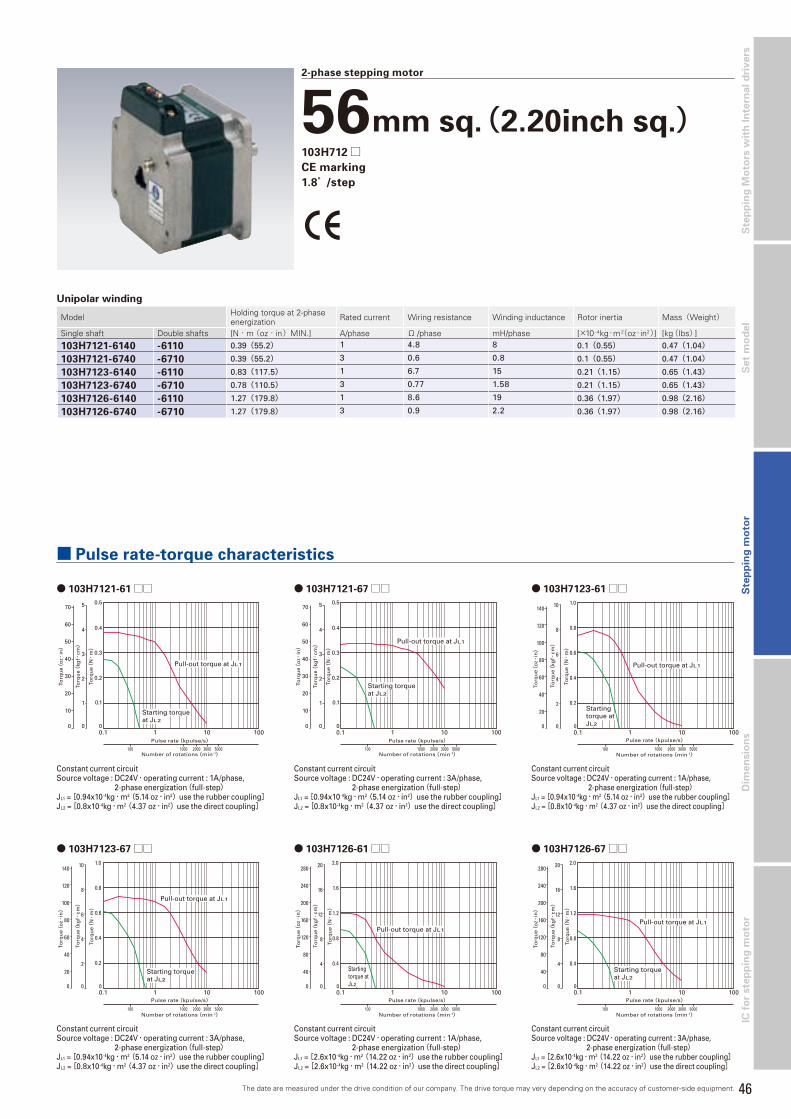
46
Dim
en
sio
ns
Ste
pp
ing
Mo
tors
wit
h I
nte
rna
l d
riv
ers
S
tep
pin
g m
oto
rS
et
mo
de
lIC
fo
r ste
pp
ing
mo
tor
● 103H7121-61□□ ● 103H7121-67□□ ● 103H7123-61□□
● 103H7123-67□□ ● 103H7126-61□□ ● 103H7126-67□□
2-phase stepping motor
56mm sq.(2.20inch sq.)103H712□CE marking
1.8°/step
0.1 1 10 100
1000 2000 3000 5000100
Pulse rate(kpulse/s)
Number of rotations(min-1)
70
0
60
50
40
30
20
10
Torq
ue(
kgf・
cm)
Torq
ue(
oz・
in)
Torq
ue(
N・
m)
1
2
3
4
5
0
0.1
0.2
0.3
0.4
0.5
0
Pull-out torque at JL1
Starting torqueat JL2
0.1 1 10 100
1000 2000 3000 5000100
Pulse rate(kpulse/s)
Number of rotations(min-1)
70
0
60
50
40
30
20
10
Torq
ue(
kgf・
cm)
Torq
ue(
oz・
in)
Torq
ue(
N・
m)
1
2
3
4
5
0
0.1
0.2
0.3
0.4
0.5
0
Pull-out torque at JL1
Starting torqueat JL2
0.1 1 10 100
1000 2000 3000 5000100
Startingtorque atJL2
Pulse rate(kpulse/s)
Number of rotations(min-1)
Pull-out torque at JL1
140
0
120
100
80
60
40
20
10
8
6
4
2
0 0
0.2
0.4
0.6
0.8
1.0
Torq
ue(
kgf・
cm)
Torq
ue(
oz・
in)
Torq
ue(
N・
m)
0.1 1 10 100
1000 2000 3000 5000100
Pulse rate(kpulse/s)
Number of rotations(min-1)
Starting torqueat JL2
Pull-out torque at JL1
140
0
120
100
80
60
40
20
10
8
6
4
2
0 0
0.2
0.4
0.6
0.8
1.0
Torq
ue(
kgf・
cm)
Torq
ue(
oz・
in)
Torq
ue(
N・
m)
0.1 1 10 100
1000 2000 3000 5000100
Pulse rate(kpulse/s)
Number of rotations(min-1)
Pull-out torque at JL1
280
0
240
200
160
120
80
40
20
16
12
8
4
0 0
0.4
0.8
1.2
1.6
2.0
Torq
ue(
kgf・
cm)
Torq
ue(
oz・
in)
Torq
ue(
N・
m)
Startingtorque atJL2
0.1 1 10 100
1000 2000 3000 5000100
Pulse rate(kpulse/s)
Number of rotations(min-1)
Starting torqueat JL2
Pull-out torque at JL1
280
0
240
200
160
120
80
40
20
16
12
8
4
0 0
0.4
0.8
1.2
1.6
2.0
Torq
ue(
kgf・
cm)
Torq
ue(
oz・
in)
Torq
ue(
N・
m)
Unipolar winding
Model Holding torque at 2-phase energization Rated current Wiring resistance Winding inductance Rotor inertia Mass(Weight)
Single shaft Double shafts [N・m (oz・in)MIN.] A/phase Ω /phase mH/phase [×10- 4kg・m2(oz・in2)] [kg(Ibs)]
103H7121-6140 -6110 0.39(55.2) 1 4.8 8 0.1(0.55) 0.47(1.04)
103H7121-6740 -6710 0.39(55.2) 3 0.6 0.8 0.1(0.55) 0.47(1.04)
103H7123-6140 -6110 0.83(117.5) 1 6.7 15 0.21(1.15) 0.65(1.43)
103H7123-6740 -6710 0.78(110.5) 3 0.77 1.58 0.21(1.15) 0.65(1.43)
103H7126-6140 -6110 1.27(179.8) 1 8.6 19 0.36(1.97) 0.98(2.16)
103H7126-6740 -6710 1.27(179.8) 3 0.9 2.2 0.36(1.97) 0.98(2.16)
Constant current circuitSource voltage : DC24V・operating current : 1A/phase,
2-phase energization(full-step)JL1 = [0.94x10⁻⁴kg・m2(5.14 oz・in2)use the rubber coupling]JL2 = [0.8x10⁻⁴kg・m2(4.37 oz・in2)use the direct coupling]
Constant current circuitSource voltage : DC24V・operating current : 3A/phase,
2-phase energization(full-step)JL1 = [0.94x10⁻⁴kg・m2(5.14 oz・in2)use the rubber coupling]JL2 = [0.8x10⁻⁴kg・m2(4.37 oz・in2)use the direct coupling]
Constant current circuitSource voltage : DC24V・operating current : 1A/phase,
2-phase energization(full-step)JL1 = [2.6x10⁻⁴kg・m2(14.22 oz・in2)use the rubber coupling]JL2 = [2.6x10⁻⁴kg・m2(14.22 oz・in2)use the direct coupling]
Constant current circuitSource voltage : DC24V・operating current : 3A/phase, 2-phase energization(full-step)JL1 = [2.6x10⁻⁴kg・m2(14.22 oz・in2)use the rubber coupling]JL2 = [2.6x10⁻⁴kg・m2(14.22 oz・in2)use the direct coupling]
Constant current circuitSource voltage : DC24V・operating current : 1A/phase, 2-phase energization(full-step)JL1 = [0.94x10⁻⁴kg・m2(5.14 oz・in2)use the rubber coupling]JL2 = [0.8x10⁻⁴kg・m2(4.37 oz・in2)use the direct coupling]
Constant current circuitSource voltage : DC24V・operating current : 3A/phase,
2-phase energization(full-step)JL1 = [0.94x10⁻⁴kg・m2(5.14 oz・in2)use the rubber coupling]JL2 = [0.8x10⁻⁴kg・m2(4.37 oz・in2)use the direct coupling]
■ Pulse rate-torque characteristics
The date are measured under the drive condition of our company. The drive torque may very depending on the accuracy of customer-side equipment.

47
Stepping motor
2-phase STEPPING SYSTEMS
Specifications
● 103H8221-62□□ ● 103H8222-63□□ ● 103H8223-63□□
2-phase stepping motor
86mm cir.(3.39inch cir.)103H822□CE marking
1.8°/step
0.1 1 10 100
1000 2000 3000 5000100
Pulse rate(kpulse/s)
Number of rotations(min-1)
Torq
ue(
kgf・
cm)
Torq
ue(
oz・
in)
Torq
ue(
N・
m)
Pull-out torque at JL1
Starting torqueat JL2
700
0
600
500
400
300
200
10010
20
30
40
50
0
1.0
2.0
3.0
4.0
5.0
00.1 1 10 100
1000 2000 3000 5000100
Pulse rate(kpulse/s)
Number of rotations(min-1)
Torq
ue(
kgf・
cm)
Torq
ue(
oz・
in)
Torq
ue(
N・
m)
Pull-out torque at JL1
Starting torqueat JL2
700
0
600
500
400
300
200
10010
20
30
40
50
0
1.0
2.0
3.0
4.0
5.0
00.1 1 10 100
1000 2000 3000 5000100
Pulse rate(kpulse/s)
Number of rotations(min-1)
Starting torqueat JL2
Pull-out torque at JL1
1400
0
1200
1000
800
600
400
200
100
80
60
40
20
0 0
2
4
6
8
10
Torq
ue(
kgf・
cm)
Torq
ue(
oz・
in)
Torq
ue(
N・
m)
Bipolar winding
Model Holding torque at 2-phase energization Rated current Wiring resistance Winding inductance Rotor inertia Mass(Weight)
Single shaft Double shafts [N・m (oz・in)MIN.] A/phase Ω /phase mH/phase [×10- 4kg・m2(oz・in2)] [kg(Ibs)]
103H8221-6240 -6210 2.74(388.0) 6 0.3 1.65 1.45(7.93) 1.5(3.31)
103H8222-6340 -6310 5.09(720.8) 6 0.35 2.7 2.9(15.86) 2.5(5.51)
103H8223-6340 -6310 7.44(1053.6) 6 0.45 3.4 4.4(24.06) 3.5(7.72)
Constant current circuitSource voltage : AC100V・operating current : 6A/phase,
2-phase energization(full-step)JL1 = [7.4x10⁻⁴kg・m2(40.46 oz・in2)use the rubber coupling]JL2 = [7.4x10⁻⁴kg・m2(40.46 oz・in2)use the direct coupling]
Constant current circuitSource voltage : AC100V・operating current : 6A/phase,
2-phase energization(full-step)JL1 = [15.3x10⁻⁴kg・m2(83.65 oz・in2)use the rubber coupling]JL2 = [15.3x10⁻⁴kg・m2(83.65 oz・in2)use the direct coupling]
Constant current circuitSource voltage : AC100V・operating current : 6A/phase,
2-phase energization(full-step)JL1 = [43x10-4kg・m2(235.10 oz・in2)use the rubber coupling]JL2 = [43x10-4kg・m2(235.10 oz・in2)use the direct coupling]
■ Pulse rate-torque characteristics
The date are measured under the drive condition of our company. The drive torque may very depending on the accuracy of customer-side equipment.
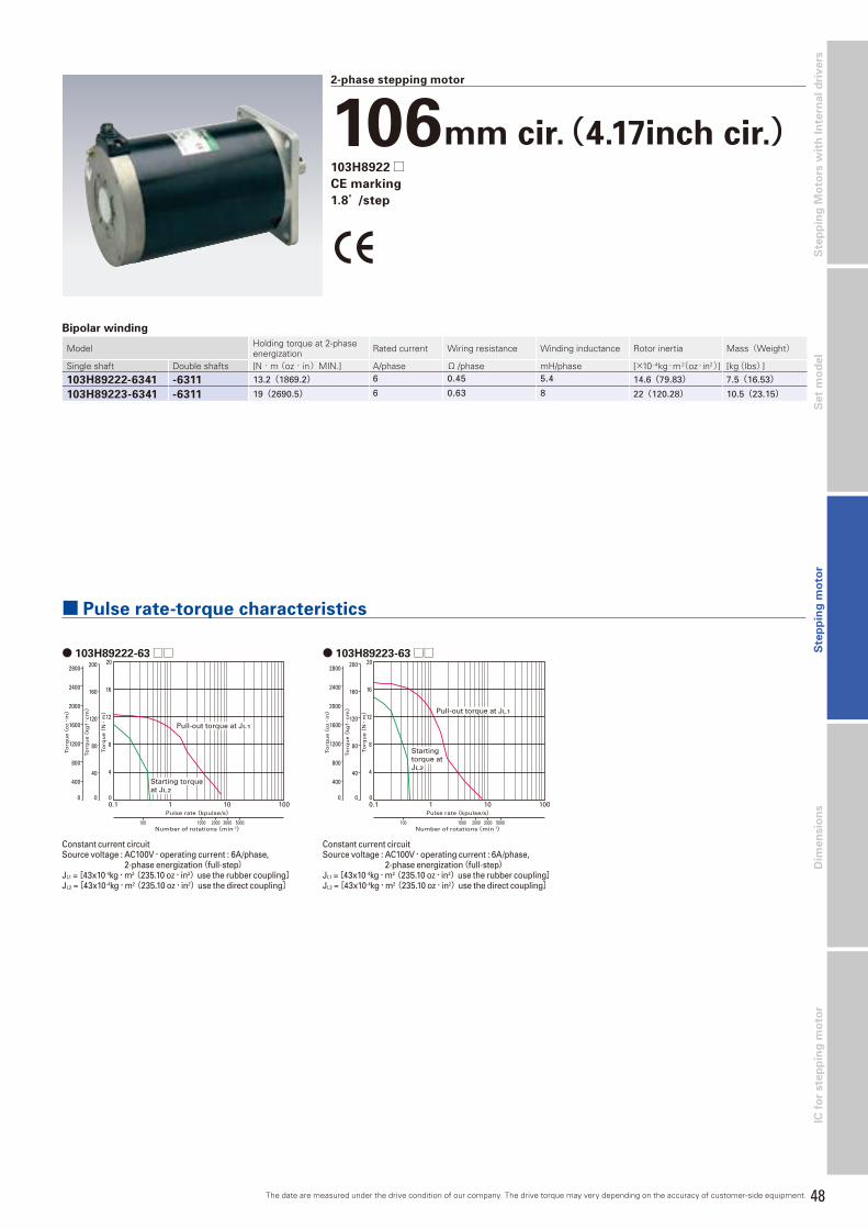
48
Dim
en
sio
ns
Ste
pp
ing
Mo
tors
wit
h I
nte
rna
l d
riv
ers
S
tep
pin
g m
oto
rS
et
mo
de
lIC
fo
r ste
pp
ing
mo
tor
● 103H89222-63□□ ● 103H89223-63□□
2-phase stepping motor
106mm cir.(4.17inch cir.)103H8922□CE marking
1.8°/step
0.1 1 10 100
1000 2000 3000 5000100
Pulse rate(kpulse/s)
Number of rotations(min-1)
Starting torqueat JL2
Pull-out torque at JL1
2800
0
2400
2000
1600
1200
800
400
200
160
120
80
40
0 0
4
8
12
16
20
To
rqu
e(kg
f・cm)
To
rqu
e(o
z・in)
To
rqu
e(N・
m)
0.1 1 10 100
1000 2000 3000 5000100
Pulse rate(kpulse/s)
Number of rotations(min-1)
Pull-out torque at JL1
2800
0
2400
2000
1600
1200
800
400
200
160
120
80
40
0 0
4
8
12
16
20
To
rqu
e(kg
f・cm)
To
rqu
e(o
z・in)
To
rqu
e(N・
m)
Startingtorque atJL2
Bipolar winding
Model Holding torque at 2-phase energization Rated current Wiring resistance Winding inductance Rotor inertia Mass(Weight)
Single shaft Double shafts [N・m (oz・in)MIN.] A/phase Ω /phase mH/phase [×10- 4kg・m2(oz・in2)] [kg(Ibs)]
103H89222-6341 -6311 13.2(1869.2) 6 0.45 5.4 14.6(79.83) 7.5(16.53)
103H89223-6341 -6311 19(2690.5) 6 0.63 8 22(120.28) 10.5(23.15)
Constant current circuitSource voltage : AC100V・operating current : 6A/phase,
2-phase energization(full-step)JL1 = [43x10-4kg・m2(235.10 oz・in2)use the rubber coupling]JL2 = [43x10-4kg・m2(235.10 oz・in2)use the direct coupling]
Constant current circuitSource voltage : AC100V・operating current : 6A/phase,
2-phase energization(full-step)JL1 = [43x10-4kg・m2(235.10 oz・in2)use the rubber coupling]JL2 = [43x10-4kg・m2(235.10 oz・in2)use the direct coupling]
■ Pulse rate-torque characteristics
The date are measured under the drive condition of our company. The drive torque may very depending on the accuracy of customer-side equipment.

49
Stepping motor
2-phase STEPPING SYSTEMS
Specifications
Model Number 103H712□ 103H822□/ 103H8922□Rated voltage 12-200VDC 12-300VDC Applied standards(Low voltage diretive)
EN60034-1,IEC34-5(EN60034-5),EN60204-1,EN60950,EN61010-1
Operation type S1(continuous rating)Protection grade IP43Device category Class IOperation environment Pollution degree 2Insulation classI Class B(130℃)Insulation resistance 100M ohm MIN. against DC500V
Withstand voltage□56mm(□2.2inch) : AC1500V 50/60Hz for 1 minuteφ 86mm(φ 3.39inch)φ 106mm(φ 4.17inch) : AC1600V 50/60Hz for 1 minute
Ambient operation temperature -10 to +50°CAmbient operation humidity 90% MAX. at less than 40°C, 57% MAX. at less than 50°C , 35% MAX. at 60°C(no condensation)Winding temperature rise 80K MAX.(Based on Sanyo Denki standard)
CE marked models
Standard modelsMotor type H series motorModel number 103H52□□ /103H67□□ /103H71□□ /103H78□□Insulation class Class B(130℃)Withstand voltage □42(□1.65inch):AC500V 50/60Hz for 1 minute, □50(□1.97inch)・□56(□2.20inch)・□60(□2.36inch):AC1000V 50/60Hz for 1 minuteInsulation resistance 100M ohm MIN. against DC500VVibration resistance Amplitude of 1.52mm(0.06inch)(P-P)at frequency range 10 to 500Hz for 15 minutes sweep time along X, Y, and Z axes for 12 times.Impact resistance 490m/s2 of acceleration for 11 ms with half-sine wave applying three times for X, Y, and Z axes each, 18 times in total.Operating ambient temperature -10℃ to 50℃
Operating ambient humidity 90%MAX. : 40℃MAX., 57%MAX. : 50℃MAX., 35%MAX. : 60℃MAX.(no condensation)
Motor type SH series motorMotor model number SH228 □□ , SH353□□ , SH142□□ , SH160 □□ , SH286 □ , Insulation class Class B(130℃)
Withstand voltage□28(□1.10inch)・□35(□1.38inch)・□42(□1.65inch):AC500V 50/60Hz for 1 minute, □60(□2.36inch)/ □86(□3.38inch):AC1000V 50/60Hz for 1 minute
Insulation resistance 100M ohm MIN. against DC500VVibration resistance Amplitude of 1.52mm(0.06inch)(P-P)at frequency range 10 to 500Hz for 15 minutes sweep time along X, Y, and Z axes for 12 times.Impact resistance 490m/s2 of acceleration for 11 ms with half-sine wave applying three times for X, Y, and Z axes each, 18 times in total.Operating ambient temperature -10℃ to 50℃
Operating ambient humidity 90%MAX. : 40℃MAX., 57%MAX. : 50℃MAX., 35%MAX. : 60℃MAX.(no condensation)
Motor type SM series motorModel number SM286□Type S1(continuous operation)Insulation class Class F(+155°C )Operation altitude 1000m(3280 feet)MAX above sea levelWithstand voltage □86mm(□3.39inch) : AC1500V 50/60Hz for 1 minuteInsulation resistance 100M ohm MIN. against DC500VProtection grade IP43Vibration resistance Amplitude of 1.52mm(0.06inch)(P-P)at frequency range 10 to 500Hz for 15 minutes sweep time along X, Y, and Z axes for 12 times. Impact resistance 490m/s2 of acceleration for 11 ms with half-sine wave applying three times for X, Y, and Z axes each, 18 times in total.Ambient operation temperature -10 to +50°CAmbient operation humidity 90% MAX. at less than 40°C, 57% MAX. at less than 50°C , 35% MAX. at 60°C(no condensation)
Radial load
Thrust load
Allowable radial / thrust load
Frange size Model numberDistance from end of shaft : mm(inch)
Thrust loadN(Ibs)0 5(0.20) 10(0.39) 15(0.59)
Radial load : N(lbs)□28mm(□1.10inch) SH228□ 42(9) 48(10) 56(12) 66(14) 3(0.67)□35mm(□1.38inch) SH353□ 40(8) 50(11) 67(15) 98(22) 10(2.25)
□42mm(□1.65inch)103H52□□ 103-59□SH142□
22(4) 26(5) 33(7) 46(10) 10(2.25)
□50mm(□1.97inch) 103H670□ 71(15) 87(19) 115(25) 167(37) 15(3.37)
□56mm(□2.20inch)103H712□ 52(11) 65(14) 85(19) 123(27) 15(3.37)103H7128 85(19) 105(23) 138(31) 200(44) 15(3.37)
□60mm(□2.36inch) 103H782□SH160□ 70(15) 87(19) 114(25) 165(37) 20(4.50)
□86mm(□3.39inch) SM286□SH286□ 167(37) 193(43) 229(51) 280(62) 60(13.488)
φ 86mm(φ 3.39inch) 103H822□ 191(42) 234(52) 301(67) 421(93) 60(13.488)φ 106mm(φ 4.17inch) 103H8922□ 321(72) 356(79) 401(90) 457(101) 100(22.48)

50
Dim
en
sio
ns
Ste
pp
ing
Mo
tors
wit
h I
nte
rna
l d
riv
ers
S
tep
pin
g m
oto
rS
et
mo
de
lIC
fo
r ste
pp
ing
mo
tor
Internal Wiring and Rotation Direction
Direction of motor rotateThe output shaft shall rotate clockwise as seen from the shaft side,
when excited by DC in the following order.(2)
(1)
(3)
(5) (6) (4)
Internal wire connec tion( ) connector pin number
● 103H52□□ Connector type
(2)
(1)
(3)
(4) (6) (5)
Internal wire connec tion( ) connector pin number
● 103H782□ Connector type
Orange
White
Blue
Red YellowBlack
Internal wire connec tion
● Lead wire type
Direction of motor rotateThe output shaft shall rotate clockwise as seen from the shaft side,
when excited by DC in the following order.
Connector type pin number
Exc
itin
go
rde
r
(1.6)
+
+
+
+
1
2
3
4
(5)
-
-
(3)
-
-
(4)
-
-
(2)
-
-
Direction of motor rotateThe output shaft shall rotate clockwise as seen from the shaft side,
when excited by DC in the following order.
Exc
itin
go
rde
r(1.6)
+
+
+
+
1
2
3
4
(4)
-
-
(3)
-
-
(5)
-
-
(2)
-
-
Connector type pin numberE
xcit
ing
ord
er
White& black
+
+
+
+
1
2
3
4
Red
-
-
Blue
-
-
Yellow
-
-
Orange
-
-
Lead wire color
Bipolar winding
Red Yellow
(1)Orange
(2)Blue
(3) (4)
Internal wire connec tion( ) connector pin number
Direction of motor rotateThe output shaft shall rotate clockwise as seen from the shaft side,
when excited by DC in the following order.
Lead wire color, connector type pin teminal blocknumber
Lead wire
Conn
ecto
rE
xcit
ing
ord
er 1
2
3
4
103H782 □
SM286□
Red–
+
+
–
(3)
(3)
Blue–
–
+
+
(2)
(2)
Yellow+
–
–
+
(4)
(4)
Orange+
+
–
–
(1)
(1)
Tem
inal
bloc
k
Unipolar winding

51
Dimensions
2-phase STEPPING SYSTEMS
▽:Motor shaft specification code
Motor shaft spec Set type code Motor type codeSingle shaft S 7Double shafts D 3
△:Motor shaft specification code
Motor shaft spec Set type code Motor type codeSingle shaft S 4Double shafts D 1
□42mm(□1.65inch)
18以下
15±1
300M
AX
A
B
Effective tapping depth depth 4(.16) MIN.4-M3 x0.5
L±0.5 24±0.5
□42±0.25
4-31±0.25
Pin No.1 · · · 6
15±1
0.01
3ø
5-0.
013
0.01
3ø
5-0.
013
0.05
ø22
-0.0
5
(.59±.04) (L±.02) (.94±.02)
.000
03(ø
.196
8-.0
005)
.000
03ø
.196
8-.0
005)
.000
3(ø
.87-
.002
)
(□1.65±.01)
(4-1.22±.01)27(1.06) MAX.
7(.2
8)M
AX
.
1.5±0.76(.59±.03)28(1.1)MIN.11(.44)
MAX.
BA
Lead wire typeConnector type
Set part number Motor model numberMotor length : mm(inch)
Cable type
Unipolar
DU15H521▽ 103H5205-04△ 0 33(1.25) ConnectorDU15H522▽ 103H5208-04△ 0 39(1.54) ConnectorDU15H524▽ 103H5210-04△ 0 48(1.89) Connectorー 103H5209-04△ 0 41(1.61) Connector
18MAX
5MA
X
Set part number Motor model numberMotor length : mm(inch)
Cable type
UnipolarDU15S141▽ SH1421-04▽ 1 33(1.25) Lead wireDU15S142▽ SH1422-04▽ 1 39(1.54) Lead wireDU15S144▽ SH1424-04▽ 1 48(1.89) Lead wire
BipolarDB16H141▽ SH1421-52▽ 1 33(1.25) Lead wireDB16H142▽ SH1422-52▽ 1 39(1.54) Lead wireDB16H144▽ SH1424-52▽ 1 48(1.89) Lead wire
□42mm(□1.65inch)42±0.25
4-31±0.254-M3×0.5
Lead wire: UL3385 AWG24
300MIN
(11.81MIN.)
R3MIN (R.12MIN.)
Cross section S-S
S
S
( 1.65±.01)
24±0.5(.94±.02)
L ±0.8(L±.02)
15±1(.59±.04)
4.5±0.15(.1771±.0059)
4.5±0.15(.1771±.0059)
1.5±0.76(.06±.03)
(4-1.22±.01)
φ22-0.05
0
φ5-0.013
0
15 0+1
φ.8661-.0019
.0000
φ.1968-.0005
.0000
φ5-0.013
0
φ.1968-.0005
.0000
.59 .00+.04
Lead wire type
□35mm(□1.65inch)
L±1(2.05±.04)
20±0.5(.79±.02)
40(1.57)MIN.2±0.25(.08±.01)
φ5-
0.01
30 φ
5-0.
013
0
300(1
1.81)M
IN.
4-M3×0.5
φ35.6(φ1.40) only stator part
Lead wire:UL1007 CSA,AWG26
Effective tapping depth 4(.16) MIN.
φ.1
968-
.000
5.0
000
(
)
φ.1
968-
.000
5.0
000
(
)
26±
0.25
29±
0.25
15±1(.59±.04)9(.35)MAX.
□35±0.5(□1.38±.02)29±0.25(1.14±.01)
26±0.25(1.02±.01)
22(.87)MAX.
5(.2
0)M
AX
.(1
.02±
.01)
(1.1
4 ±.0
1)
Set part number Motor model numberMotor length : mm(inch)
Cable type
Unipolarー SH3533-12U△ 0 33(1.25) Lead wireー SH3537-12U△ 0 37(1.54) Lead wireー SH3552-12U△ 0 52(1.89) Lead wire
Lead wire type
.06±.03
A
ø.1
97-.
0005
0ø
.866
-.00
2
0 4-M3 x 0.5.16 MIN.DP.
1.22
±.01
1.22±.01
.71MAX.
□1.65±.01
+.04
.177±.006
.94±.02
R.12MIN.
.2M
AX
.
L±.02
.94MIN.24MIN.
.24MAX.
.591±.04
ø.1
97-.
0005
0
.59 0
□42mm(□1.65inch)
Lead wire typeConnector type
Set part number Motor model numberMotor length : mm(inch)
Cable type
Bipolar
DB14H521▽ 103H5205-52△ 0 33(1.25) Lead wireDB14H522▽ 103H5208-52△ 0 39(1.54) Lead wireDB14H524▽ 103H5210-52△ 0 48(1.89) Lead wireー 103H5205-50△ 0 33(1.25) Lead wireー 103H5205-51△ 0 33(1.25) Lead wireー 103H5208-50△ 0 39(1.54) Lead wireー 103H5208-51△ 0 39(1.54) Lead wireー 103H5209-50△ 0 41(1.61) Lead wireー 103H5209-51△ 0 41(1.61) Lead wireー 103H5209-52△ 0 41(1.61) Lead wireー 103H5210-50△ 0 48(1.89) Lead wireー 103H5210-51△ 0 48(1.89) Lead wire
Motors[Unit: mm(inch)]
□28mm(□1.10inch)
Lead wire typeConnector type
4.5±0.15(.17771±0.059)
□28±0.5(□1.10±0.2)4-23±0.25
(4-.91±0.01)
4-M2.5×0.45
0.01
3φ
5-0.
013
.000
0 (φ
.196
8-.0
005)
0.13
φ22
-0.0
5.0
000
(φ.8
661-
.001
9)
+110 0
+.04(.39 .00)
(Effective lenght)
Lead wire:UL3265 AWG28L±0.8(L±0.3)
15±0.5(.59±0.2)
1.5±0.76(.06±0.3)
(R.12 MIN.)R3MAX.
0.01
3φ
5-0.
013
.000
0 (φ
.196
8-.0
005)
10±1(.39±0.4)
11.8
1MIN
.30
0MA
X.
S
S4.5±0.15
(.1771±0.059)Cross section S-S
Set part number Motor model numberMotor length : mm(inch)
Cable type
Unipolar
DU14S281▽ SH2281-51▽ 1 32(1.26) Lead wireDU14S281▽ SH2281-52▽ 1 32(1.26) Lead wireDU14S285▽ SH2285-51▽ 1 51.5(2.03) Lead wireDU14S285▽ SH2285-52▽ 1 51.5(2.03) Lead wire
Bipolar
DB14S281▽ SH2281-56▽ 1 32(1.26) Lead wireDB14S281▽ SH2281-57▽ 1 32(1.26) Lead wireDB14S285▽ SH2285-56▽ 1 51.5(2.03) Lead wireDB14S285▽ SH2285-57▽ 1 51.5(2.03) Lead wire
N.P
(11.
8MIN
.)
(.20±.04) (L±.02)
(.28±.02)
(Ø .1
968-
.000
5).0
000
(Ø .1
968-
.000
5)
(Ø .8
661-
.001
9).0
000
.000
0
(□1.65±.020)
(2-1.22±.012)
( .94MAX.)
( .2
0MA
X.)
2-31±0.3
24MAX.
□42±0.5
5MA
X.
300M
IN.
Lead wire UL1007 AWG26
7±0.5
Ø22
0 -0.0
5
Ø5 0 -0
.013
5±1 L±0.5
0 -0.0
13
2-M3×0.5
Ø5
□42mm(□1.65inch)
Lead wire type
Set part number Motor model numberMotor length : mm(inch)
Cable type
Bipolarー SS2421-50△1 11.6(.457) Lead wireー SS2422-50△1 18.6(.732) Lead wireー SS2423-50△1 25.6(1.008) Lead wire

52
Dim
en
sio
ns
Ste
pp
ing
Mo
tors
wit
h I
nte
rna
l d
riv
ers
S
tep
pin
g m
oto
rS
et
mo
de
lIC
fo
r ste
pp
ing
mo
tor
+0.54-ø4.5 0.0
+.02(4-ø.18 .00 )
8(.3
1)M
AX
.
26(1.02) MAX.
Lead wire UL1430 AWG22
305(
12)M
IN.
15.5±1(.61±.04) (L±.03)
(.81±.02)
L±0.8
20.6±0.5
□56±0.5
(□2.20±.02)
(4-1.86±.0005)4-47.14±0.13
5(.20)
(.06)1.5
0.00
0ø
6.35
-0.0
13.0
0000
(ø.2
5-.0
005)
.000
00(ø
.25-
.000
5)
0.00
0ø
6.35
-0.0
13
ø38
.1±
0.02
5
(ø1.
50±
.001
)
□56mm(□2.20inch)
Lead wire type
Set part number Motor model numberMotor length : mm(inch)
Cable type
Unipolar
DU16H711△ 103H7121-04△ 0 41.8(1.65) Lead wireDU16H713△ 103H7123-04△ 0 53.8(2.12) Lead wireDU16H716△ 103H7126-04△ 0 75.8(2.98) Lead wireー 103H7121-01△ 0 41.8(1.65) Lead wireー 103H7121-07△ 0 41.8(1.65) Lead wireー 103H7123-01△ 0 53.8(2.12) Lead wireー 103H7123-07△ 0 53.8(2.12) Lead wireー 103H7124-01△ 0 63.8(2.51) Lead wireー 103H7124-04△ 0 63.8(2.51) Lead wireー 103H7124-07△ 0 63.8(2.51) Lead wireー 103H7126-01△ 0 75.8(2.98) Lead wireー 103H7126-07△ 0 75.8(2.98) Lead wire
□50mm(□1.97inch)
Lead wire type
Set part number Motor model numberMotor length : mm(inch)
Cable type
Unipolar
ー 103H6701-01△ 0 39.8(1.57) Lead wireー 103H6701-04△ 0 39.8(1.57) Lead wireー 103H6701-07△ 0 39.8(1.57) Lead wireー 103H6703-01△ 0 51.3(2.02) Lead wireー 103H6703-04△ 0 51.3(2.02) Lead wireー 103H6703-07△ 0 51.3(2.02) Lead wireー 103H6704-01△ 0 55.8(2.20) Lead wireー 103H6704-04△ 0 55.8(2.20) Lead wireー 103H6704-07△ 0 55.8(2.20) Lead wire
BipolarDB16H671▽ 103H6701-50△ 0 39.8(1.57) Lead wireDB16H672▽ 103H6703-50△ 0 51.3(2.02) Lead wireー 103H6704-50△ 0 55.8(2.20) Lead wire
15.5±1(.61±.04) (L±.03) (.81±.02)
L±0.8 20.6±0.5
□50±0.5(□1.97±.02)
(4-1.61±.005)4-41±0.13
Lead wire UL3266 AWG22
+0.54-ø4.5 0.5
+.02(4-ø.18 .00)
6(.2
4)M
AX
.
25(.98)MAX.305(
12)M
IN.
1.5(.06)5
(.2)
0.00
0ø
6.35
-0.0
13.0
000 0
(ø.2
5-.0
005)
.000
00(ø
.25-
.000
5).0
000
(ø1.
42-.
002)
0.00
0ø
36-0
.039
0 .00
0ø
6.35
-0.0
13
△:Motor shaft specification code
Motor shaft spec Set type code Motor type codeSingle shaft S 4Double shafts D 1
Model number Shaft diameter(D) Dcut thickness(L)
103H7121-□□□□φ 6.35 5.8103H7123-□□□□
103H7126-□□□□103H7128-□□□□ φ 8 7.5
▽:Motor shaft specification code
Motor shaft spec Set type code Motor type codeSingle shaft S 7Double shafts D 3
Set part number Motor model numberMotor length : mm(inch)
Cable type
Bipolarー SS2501-50△1 11(.433) Lead wireー SS2502-50△1 16(.63) Lead wire
□50mm(□1.97inch)
N.P
300M
IN.
(11.8
1MIN
.)
Lead wire UL1007 AWG26
5±1(0.20±0.04)
L±0.3(L±0.012)
(0.20±0.012)5±0.3
Ø5
0 -0.0
13
(Ø0.1
968-
0.000
5)0.0
000
0 -0.0
13
(Ø0.1
968-
0.000
5)0.0
000
4-M2.5×0.45 4-41±0.3
50±0.5( 1.97±0.020)
(4-1.61±0.012)
66.5±0.025
(Ø2.618±
0.001)
Ø5
Lead wire type
R.P
B
11(.
44)
MA
X.
A
Lead wire UL1430 CSA, AWG22
0.00
0ø
6.35
-0.0
13.0
0000
(ø.2
5-.0
005)
0.00
0ø
6.35
-0.0
13.0
000 0
(ø.2
5-.0
005)
15.5±1
(.61±.04) (L±.03)L±0.8
ø38
.1±
0.02
5(ø
1.50±
.001
)
□56±0.5(2.20±.02)
(1.86±.0005)4-47.14±0.13
+0.54-ø4.5 0 5
+0.2(4-ø1.8 .00)
(.06±.0098)1.5±0.25
(.2±.0098)5±0.25
(.81±.02)20.6±0.5
□56mm(□2.20inch)
Lead wire type
Set part number Motor model numberMotor length : mm(inch)
Cable type
Unipolar
ー 103H7121-61△ 0 41.8(1.65) Lead wire(CE)ー 103H7121-67△ 0 41.8(1.65) Lead wire(CE)ー 103H7123-61△ 0 53.8(2.12) Lead wire(CE)ー 103H7123-67△ 0 53.8(2.12) Lead wire(CE)ー 103H7126-61△ 0 75.8(2.98) Lead wire(CE)ー 103H7126-67△ 0 75.8(2.98) Lead wire(CE)

53
2-phase STEPPING SYSTEMS
Dimensions
◇:Motor shaft specification code
Motor shaft spec Set type code Motor type codeSingle shaft S 5
Double shafts D 2
A(CE)
B(CE)
CE type
□86mm(□3.39inch)
Lead wire type
Set part number Motor model numberMotor length : mm(inch)
Cable type
Unipolarー SH2861-04△1 66(2.6) Lead wireー SH2862-04△1 96.5(3.8) Lead wireー SH2863-04△1 127(5) Lead wire
Bipolar
ー SM2861-50 ◇1 66(2.6) Lead wire(CE)ー SM2861-51◇1 66(2.6) Lead wire(CE)ー SM2861-52◇1 66(2.6) Lead wire(CE)ー SM2862-50 ◇1 96.5(3.8) Lead wire(CE)ー SM2862-51◇1 96.5(3.8) Lead wire(CE)ー SM2862-52◇1 96.5(3.8) Lead wire(CE)ー SM2863-50 ◇1 127(5) Lead wire(CE)ー SM2863-51◇1 127(5) Lead wire(CE)ー SM2863-52◇1 127(5) Lead wire(CE)
27(1.06)MAX.
12(.4
7)M
AX
.69
.6±0
.25(
2.74
±0.1
)85
.5±0
.5(3
.366
±0.2
)
69.6±0.25(2.74±0.1)85.5±0.5(3.366±0.2)
4-φ5.6±0.2(4-φ.2205±.0079)
L±1(L±0.4)30±1(1.18±.04)1.5±0.25(.06±0.1)
8±0.5(.31±0.1)30±0.5(1.18±0.1)
S
S
S
S
13±0
.15
(.511
8±0.
059)
90°
13±0.15(.5118±0.059)
Grounding terminalM4×0.7×6L
25+0.4
0+1
0(.91 )
R4(R.16)MIN. R4(R.16)MIN.
Lead wire:UL3398 CSA AWG22
Cross sectionS-S
(Effective length)25
+0.40
+10(.91 )
(Effective length)
φ14
0
-0.0
18
(φ.5
5
)
0
-0.0
01
φ14
0
-0.0
18
(φ.5
5
)
0
-0.0
01
φ73
.025
±0.0
25(φ
2.87
5±0.
001)
A
B
△:Motor shaft specification code
Motor shaft spec Set type code Motor type codeSingle shaft S 4Double shafts D 1
□60mm(□2.36inch)
Connector type
Set part number Motor model numberMotor length : mm(inch)
Cable type
Unipolar
ー 103H7821-01△ 0 44.8(1.76) Connectorー 103H7821-04△ 0 44.8(1.76) Connectorー 103H7821-07△ 0 44.8(1.76) Connectorー 103H7822-01△ 0 53.8(2.12) Connectorー 103H7822-04△ 0 53.8(2.12) Connectorー 103H7822-07△ 0 53.8(2.12) Connectorー 103H7823-01△ 0 85.8(3.38) Connectorー 103H7823-04△ 0 85.8(3.38) Connectorー 103H7823-07△ 0 85.8(3.38) Connector
Bipolar
DB16H781△ 103H7821-57△ 0 44.8(1.76) ConnectorDB16H782△ 103H7822-57△ 0 53.8(2.12) ConnectorDB16H783△ 103H7823-57△ 0 85.8(3.38) Connectorー 103H7821-17△ 0 44.8(1.76) Connectorー 103H7822-17△ 0 53.8(2.12) Connectorー 103H7823-17△ 0 85.8(3.38) Connector
Pin No.1 · · · 6
(effective length)
(effective length)
S
S
S
S
0.00
0ø
8-0.
015
.000
0 0(ø
.315
-.00
06) .0
0000
(ø.3
15-.
0006
).0
000
(ø1.
42-.
002)
R4 MIN. R4 MIN.
+115+0
+.04(.59+.00 )+.04(.59+.00 )
15.5±1(.61±.04) (L±.03) (.81±.02)
(R.157MIN.) (R.157MIN.)
L±0.8 20.6±0.5
7(.28)
(.06)1.5
+115+0
0.00
0ø
8-0.
015
0.00
0ø
36-0
.039
33(1.30) MAX.
4-50±0.13
□60±0.5
(□2.36±.02)
(4-1.97±.005)
12(.
47)
MA
X.
+0.54-ø4.5+0.0
+.02(4-ø.18+.00).0
□60mm(□2.36inch)
Set part number Motor model numberMotor length : mm(inch)
Cable type
Unipolarー SH1601-04△ 0 42(1.65) Lead wireー SH1602-04△ 0 54(2.13) Lead wireー SH1603-04△ 0 76(2.99) Lead wire
BipolarDB16S161△ SH1601-52△ 0 42(1.65) Lead wireDB16S162△ SH1602-52△ 0 54(2.13) Lead wireDB16S163△ SH1603-52△ 0 76(2.99) Lead wire
B
A
60±
0.5
(2.
36±
0.2)
(φ
1.5±
.000
9)
(.61±.04)(L±.03)
(.2755±.0098)
(.06±.0098)
(.81±0.2) (2.36±.02)
(1.86±.0051)
.000
0 (φ
.25-
.000
5)
.000
0 (φ
D-.
0005)
+.02 (4-φ.18 .00)
15.5±1 L±0.8
7±0.25
1.5±0.25
φ38
.1±
0.02
5
20.6±0.5 □60±0.5
4-47.14±0.13
+0.54-φ4.5 0
0-0.
φ6.
3501
3
0φ
D-0
.013
N.P
Lead wire type
Lead wire UL1430 CSA, AWG22
R4MIN.
+.04
+.024-ø 4.5
+0.5
15 0
15.5±1
8MAX.
L±0.8
32.2MIN.
5±0.25
20.6±0.5
1.5±0.25
.59 0
øD
-0.0
130
ø38
.1±0
.025
56±0.5
47.14±0.13
26MAX.
8MA
X.
L±0.15
øD
-0.0
130
ø56
±0.5
+1
A
(EFFECTIVELENGTH)
(EFFECTIVE LENGTH)
B
B B
B
B
B
B
R4MIN.
(.06±.01)(1.27MIN.)
(.2±0.1)
(øD
- .0
005)
(ø1.
5±.0
01)
(.31MAX.)
(.59 0 )
(L±.03) (.81±.02)
(15 0)+1
(.61±0.4)
0
(R.16MIN.)
(ø
2.2±
.02) (ø
D-0
.005
)0
+.04
(2.2±.02)
(1.86±.01)
(1.02MAX.)
(.31
MA
X.)
(L±.006)
(4-ø .18 )
(R.16MIN.)
□56mm(□2.20inch)
Lead wire type
Set part number Motor model numberMotor length : mm(inch)
Cable type
Bipolar
DB16H711△ 103H7121-57△ 0 41.8(1.65) Lead wireDB16H713△ 103H7123-57△ 0 53.8(2.12) Lead wireDB16H716△ 103H7126-57△ 0 75.8(2.98) Lead wireー 103H7121-56△ 0 41.8(1.65) Lead wireー 103H7121-58△ 0 41.8(1.65) Lead wireー 103H7123-56△ 0 53.8(2.12) Lead wireー 103H7123-58△ 0 53.8(2.12) Lead wireー 103H7126-56△ 0 75.8(2.98) Lead wireー 103H7126-58△ 0 75.8(2.98) Lead wireー 103H7128-56△ 0 94.8(3.73) Lead wireー 103H7128-57△ 0 94.8(3.73) Lead wireー 103H7128-58△ 0 94.8(3.73) Lead wire
Motors[Unit: mm(inch)]
Model number Shaft diameter(D) Dcut thickness(L)
103H7121-□□□□φ 6.35 5.8103H7123-□□□□
103H7126-□□□□103H7128-□□□□ φ 8 7.5
Model number Shaft diameter(D) Dcut thickness(L)
SH1601-□□□□φ 6.35 5.8
SH1602-□□□□SH1603-□□□□ φ 8 7.5

54
Dim
en
sio
ns
Ste
pp
ing
Mo
tors
wit
h I
nte
rna
l d
riv
ers
S
tep
pin
g m
oto
rS
et
mo
de
lIC
fo
r ste
pp
ing
mo
tor
φ86mm(φ3.39inch)
Lead wire type
Set part number Motor model numberMotor length : mm(inch)
Cable type
Bipolarー 103H8221-62△ 0 62(3.31) Lead wire(CE)ー 103H8222-63△ 0 92.2(5.51) Lead wire(CE)ー 103H8223-63△ 0 125.9(7.72) Lead wire(CE)
Lead wire UL1430 AWG18UL vinyl tube
Grounding terminalM4x0.7x6L
305(
12)M
IN.
250±
20(9
.8±
.8)
ø86±
0.5
(ø3.
4±.0
2)0.
000
ø9.
5-0.
013
.000
00(ø
.374
-.00
05)
.000
00(ø
.472
4-.0
007)
0.00
0ø
12-0
.018
ø73
.025±
0.02
5(ø
2.9±
.001
)25(.98)
27.5±0.5
4.83
1.52
30±0.5L±0.828±1(1.10± .04) (L±.03) (1.2±.02)
(1.08±.02)
(.06)
(.19)
+0.54-ø5.35+0.0
+.02(4-ø.2+.00 )
□82.55±0.5(□3.25±.02)
4-69.6±0.2(4-2.74±.008)
+0.54-ø6.9 0.0
+.02(4-ø.27 .00 )
Lead wire UL1430 AWG18
305(
12)M
IN.
ø10
6.4±
1(ø
4.2±
.04)
(ø2.
19±
.002
)
28±1(1.10±.04) (L±.04) (1.38±.02)
L±1 35±0.5
8.6(.34)
(.06)1.52
+130.5 0
+.04(1.2 .00 )
0.00
0ø
12.7
-0.0
18
.000
00(ø
.5-.
0007
) .000
00(ø
.63-
.000
7)ø5
5.524±
0.05
4-88.9±0.25
□106.4±0.5
(□4.2±.002)
(4-3.5±.001)
0.00
0ø
16-0
.018
A(CE)
B(CE)
AB
Lead wire type CE type
Set part number Motor model numberMotor length : mm(inch)
Cable type
Unipolarー 103H89222-09△1 163.3(6.4) Lead wireー 103H89223-09△1 221.3(8.7) Lead wire
Bipolar
ー 103H89222-52△1 163.3(6.4) Lead wireー 103H89223-52△1 221.3(8.7) Lead wire(CE)ー 103H89222-63△1 163.3(6.4) Lead wire(CE)ー 103H89223-63△1 221.3(8.7) Lead wire
φ106mm(φ4.17inch)
□86mm(□3.39inch)
Terminal Block
Terminal Screw
Terminal No.
M4×8L
Cable GrandSkintop St11
Earth TerminalM4×0.7×8L
L±1.5(L±.06)
25(.98)Max.
N.P
1.5±0.25 (.06±.01)
30±0.5(1.18±.02)
(.31±.02)8±0.5
0
φ14
-0.0
18
φ73
.025
±0.0
25(φ
2.88
±.00
10)
Sheet Packing
(Effective Length)
+.04(.98 .00)
R4MIN.S
S
□85.5±0.5(3.37±.02)
(4-φ.22±.008)
4-69.6±0.25(2.74±.01)
4-φ5.6±0.2
1
2
3
4
Use propergroundingtechniques.
32(1
.26)M
ax.
+125 0
Set part number Motor model numberMotor length : mm(inch)
Cable type
Terminalblock
ー SM2861-5066 97.9(3.9) Terminal blockー SM2861-5166 97.9(3.9) Terminal blockー SM2861-5266 97.9(3.9) Terminal blockー SM2862-5066 128.4(5.1) Terminal blockー SM2862-5166 128.4(5.1) Terminal blockー SM2862-5266 128.4(5.1) Terminal blockー SM2863-5066 158.8(6.3) Terminal blockー SM2863-5166 158.8(6.3) Terminal blockー SM2863-5266 158.8(6.3) Terminal block
Terminal block type
△:Motor shaft specification code
Motor shaft spec Set type code Motor type codeSingle shaft S 4Double shafts D 1
▽:Motor shaft specification code
Motor shaft spec Set type code Motor type codeSingle shaft S 7Double shafts D 3
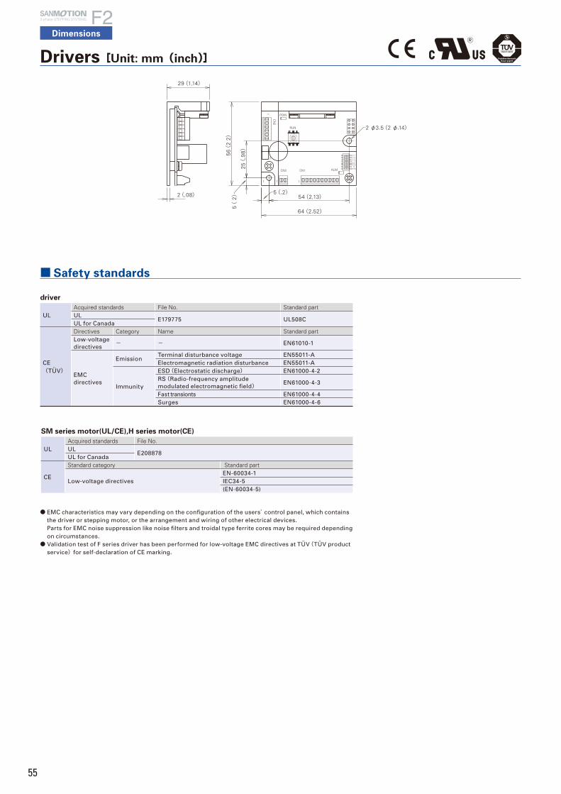
55
Drivers[Unit: mm(inch)]
■ Safety standards
2-phase STEPPING SYSTEMS
Dimensions
SM series motor(UL/CE),H series motor(CE)
ULAcquired standards File No.UL
E208878UL for Canada
CE
Standard category Standard part
Low-voltage directivesEN-60034-1IEC34-5(EN-60034-5)
driver
ULAcquired standards File No. Standard partUL
E179775 UL508CUL for Canada
CE(TÜV)
Directives Category Name Standard partLow-voltage directives
- - EN61010-1
EMC directives
EmissionTerminal disturbance voltage EN55011-AElectromagnetic radiation disturbance EN55011-A
Immunity
ESD(Electrostatic discharge) EN61000-4-2RS(Radio-frequency amplitude modulated electromagnetic field)
EN61000-4-3
Fast transionts EN61000-4-4Surges EN61000-4-6
● EMC characteristics may vary depending on the configuration of the users’ control panel, which contains the driver or stepping motor, or the arrangement and wiring of other electrical devices. Parts for EMC noise suppression like noise filters and troidal type ferrite cores may be required depending on circumstances.
● Validation test of F series driver has been performed for low-voltage EMC directives at TÜV(TÜV product service)for self-declaration of CE marking.
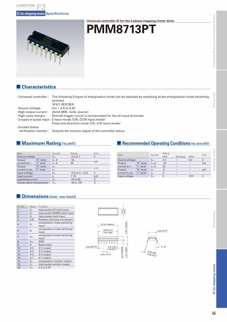
56
Dim
en
sio
ns
Ste
pp
ing
Mo
tors
wit
h I
nte
rna
l d
riv
ers
S
tep
pin
g m
oto
rS
et
mo
de
lIC
fo
r ste
pp
ing
mo
tor
IC for stepping motor
2-phase STEPPING SYSTEMS
Specifications
■ Characteristics
■Maximum Rating(Ta=25℃)
Universal controller IC for the 2-phase stepping motor drive
PMM8713PT
Item Symbol Rating UnitSource voltage VCC -0.3 to 7 VOutput currentφ n
“H” level IOH φ -35mA
“L” level IOL φ 35Output current CO,EM
“H” level IOH μA
“L” level IOL Input voltage VIN -0.3 to VCC +0.3 VInput current IIN ± 10 mAoperating current Topr -20 to 85 ℃
Conservation temperature Tstg -40 to 125 ℃
Item SymbolRating
UnitMIN. Standard MAX.
Source voltage VCC 4.5 - 5.5 VOutput currentφ n
“H” level IOH φ -24 - - mA“L” level IOL φ 24 - -
Output current CO,EM
“H” level IOH -2 - - mA“L” level IOL 2 - -
Input voltage VIN 0 - VCC V
■ Recommended Operating Conditions(Ta=-20 to 85℃)
Pin No. Name Function1. CU Input pulse UP clock input2. CD Input pulse DOWN clock input3. CK Input pulse clock input4. U/D Rotation direction conversion
5. EAenergization mode switching input
6. EBenergization mode switching input
7. φ Cenergization mode switching input
8. VSS GND9. R Reset input10. φ 4 φ 4 output11. φ 3 φ 3 output12. φ 2 φ 2 output13. φ 1 φ 1 output14. EM energization monitor output15. CO Input pulse monitor output16. VCC 4.5 to 5.5V
■ Dimensions[Unit : mm(inch)]
6.6(.2
6)4.
45(.
17)M
AX
.
6.2(.2
4)
7.62(.3)TYP
0~15˚
0.20(.008)0.35(.014)
19.75(.78)MAX.
19.25±0.2(.76±.008)
0.51
(.02
)MIN
.
2.9(
.11)
MIN
.0.4(.016)0.6(.024)
2.54(.1)TYP
1.53(.06)TYP
・Universal controller : The following 3 types of energization mode can be selected by switching at the energization mode switching terminal
1EX/1-2EX/2EX・Source voltage : Vcc = 4.5 to 5.5V・High output current : 24mA MIN.(sink, source)・High noise margin : Schmitt trigger circuit is incorporated for the all input terminals.・2 types of pulse input : 2 input mode(CW, CCW input mode) Pulse and direction mode(CK, U/D input mode)・Excited status verification monitor : Outputs the monitor signal of the controller status.

57
■ Electrical Characteristics
Direct current characteristics(Ta = -20 to 85℃)
Item SymbolCondition Standard value
UnitVCC[V] MIN. Standard MAX.
Input voltage
“H” level VIH 5 - 3.5 - - V“L” level VIL 5 - - - 1.5
Output voltage
“H” level VOH 5VH=5V VL=0V IOH=0
4.9 - - V
“L” level VOL 5VH=5V VL=0V IOH=0
- - 0.1
Output currentφ 1 to φ 4
“H” level IOH 5VH=5V VL=0V VOUT=2.4V
-24 - - mA
“L” level IOL 5VH=5V VL=0V VOUT=0.4V
24 - -
Output currentCO, EM
“H” level IOH 5VH=5V VL=0V VOUT=2.4V
-2 - - mA
“L” level IOL 5VH=5V VL=0V VOUT=0.4V
2 - -
Input current I 5 - - 10 - μ AStatic current consumption
ICC 5 VH=5V VL=0V - 1 - mA
Switching characteristics(Ta = -20 to 85℃)
Item SymbolCondition Standard value
UnitVCC[V]a MIN. Standard MAX.
MAX. clock frequency
fMAX 5tr= tf= 20ns, CL= 50pF
1 - - MHZ
MIN. width of clock pulse
tWL, tWH
5tr= tf= 20ns, CL= 50pF
- - 500 ns
MIN. width of reset pulse
tWR 5tr= tf= 20ns, CL= 50pF
- - 1000 ns
Time delay(from clock input to φ output)
tpd 5tr= tf= 20ns, CL= 50pF
- - 2000 ns
Set time tSET 5tr= tf= 20ns, CL= 50pF
0 - - ns
Holding time tHOLD 5tr= tf= 20ns, CL= 50pF
250 - - ns
Energization modes
Excitation mode
InputR EA EB φ C
1 EX H H L H1-2EX H H H H2 EX H L L H
Input modes and rotation direction
Input modeInput Rotation
directionCU CD CK U/ D
2 input mode(CW, CCW)
L L L CW
L L L CCW
Pulse and direction mode(CK, U/D)
L L H CW
L L L CCW
■ Function Table
90% 90%
50% 50%
50%
50%
50%
10% 10%
90%
90%
10%
90%
50%
50%
10%10%
tHOLD
CK
CU
CD
CK
tf
tr or tf
tr
tr
tSET
tWLtWH
tpd
U/D
1/f
φ1 to φ4
tf
Measured waveforms on switching time scale

58
Dim
en
sio
ns
Ste
pp
ing
Mo
tors
wit
h I
nte
rna
l d
riv
ers
S
tep
pin
g m
oto
rS
et
mo
de
lIC
fo
r ste
pp
ing
mo
tor
24V
P.GND
5V
5V
Reset input
Driving input
Energization mode setting
1234
567
910111213
1514
816
GND
External output
PMM8713PT
5V
5V
GNDGND
PMM2101
2 1
226
243254
9 11 15 19 810
12
14
18
5
23
13
72126
+
20
Stepping motor
GND
GND
+
1EX
Pulse0(Reset) 1 2 3 4
Faceφ 1 1 0 0 0 1φ 2 0 1 0 0 0φ 3 0 0 1 0 0φ 4 0 0 0 1 0EM 0 0 0 0 0UPDOWN
2EX
Pulse0(Reset) 1 2 3 4
Faceφ 1 1 1 0 0 1φ 2 0 1 1 0 0φ 3 0 0 1 1 0φ 4 1 0 0 1 1EM 1 1 1 1 1UPDOWN
1-2EX
Pulse0(Reset) 1 2 3 4 5 6 7 8
Faceφ 1 1 1 1 0 0 0 0 0 1φ 2 0 0 1 1 1 0 0 0 0φ 3 0 0 0 0 1 1 1 0 0φ 4 1 0 0 0 0 0 1 1 1EM 1 0 1 0 1 0 1 0 1UPDOWN
・ Reset after changing the energization mode.
Energization mode setting
Pin No. Terminal symbol Input level Motor operation
5,6 EA, EBH 1-2EXL 2EX
● The normal initial reset may not be performed during unstable VCC after turning the power ON. For reliable resetting, hold the R terminal(9-pin)at the “L” level till the VCC becomes stable.
■ Energization Sequence
■ Input Pulse Monitor
CU
CD
CK
CO
Input
Output
CV
4.5V
1.5V MAX.
Vcc (16-pin)
R (9-pin)
■ Example of Application Circuit(Bipolar wiring motor)
Combined with the power hybrid IC
● Power hybrid IC : Refer to page 47 for the PMM2101 specifications.● Refer to the PMM8713PT Operation Manual for other application circuit examples.
Universal controller IC for the 2-phase stepping motor drive
PMM8713PT
IC for stepping motor
2-phase STEPPING SYSTEMS
Specifications

59
4±0.3(.16±.012)
3.8±0.2(.15±.008)
+0.2 0.6 – 0.05
+.008 (.02 – .002 )26x1.27=33.02(26x.05=1.3)
40±0.3(1.57±.01)
25±0.2(.98±.008)ø3.3±0.2(ø.13±.008)
1.27(.05)
3.42.54(.1) (.13)
0.25(.01)
1.5±
0.2
4.5±
0.5
(.178±.
02)
13±0.3
(.51±.
011)
9±0.2
(.35±.
008)
3.3±0
.2(.13±
.008)
83.
5(.
14)
(.31)
3±0.
2(.1
2±.00
8)(.0
6±.06
)1(.04)(.04)
1 27
PMM2101
1
Control No. and Lot No.
HIC for the 2-phase stepping motor
PMM2101Full Step / Half StepBipolar
■ Characteristics
■Maximum Rating(Tc=25℃) ■ Recommended Operating Conditions(Tc=25℃)
・Enables high speed and high torque operation by using bipolar constant current switching method.・Enables compact driving circuit configuration with few of externally attached parts.・The overheat protection circuit is incorporated to assist the safety design.
■ Dimensions[Unit : mm(inch)]
Item Symbol Rated value UnitSource voltage-1 VCC1 8 to 60 VSource voltage-2 VCC2 0 to 7 VOutput current IO 1.4 AAllowable loss PT 35(Tc= 25℃) WThermal resistance
θ jc 3.57 ℃/Wθ ja 25 ℃/W
Junction temperature
Tjmax 150 ℃
Conservation temperature
Tstg -40~ 150 ℃
Item Symbol Rated value UnitSource voltage-1 VCC1 10 to 50 VSource voltage-2 VCC2 4.75 to 5.25 VOutput current IO 1.0 AOscillator frequency
FC 20 to 27 kHz
Operation temperature
TC -25 to 85 ℃
Pin No. Name Function1. VCC2 Power terminal for controller section2. ENA A Enable input terminal3. φ 1 Arm drive input4. φ 2 Arm drive input5. CR A One shot time constant setting terminal6. Vref A Motor current setting terminal7. LG A GND8. VCC1 A Motor driver power terminal9. VSA Motor current detection terminal10. M1 Motor output11. RS A Detection resistor connecting terminal12. M2 Motor output13. PG P.GND14. M3 Motor output15. RS B Detection resistor connecting terminal16. NC -
17. NC -
18. M4 Motor output19. VS B Motor current detection terminal20. VCC1 B Motor driver power terminal21. LG B GND22. Vref B Motor current setting terminal23. CR B One shot time constant setting terminal24. φ 3 Arm drive input25. φ 4 Arm drive input26. ENA B Enable terminal27. AL Overheat alarm output terminal
Operational truth value table
ENA A(ENA B) φ 1(φ 3) φ 2(φ 4) M1(M3) M2(M4)L L L OFF OFFL L H L HL H L H LL H H OFF OFFH - - OFF OFF
IC for stepping motor
2-phase STEPPING SYSTEMS
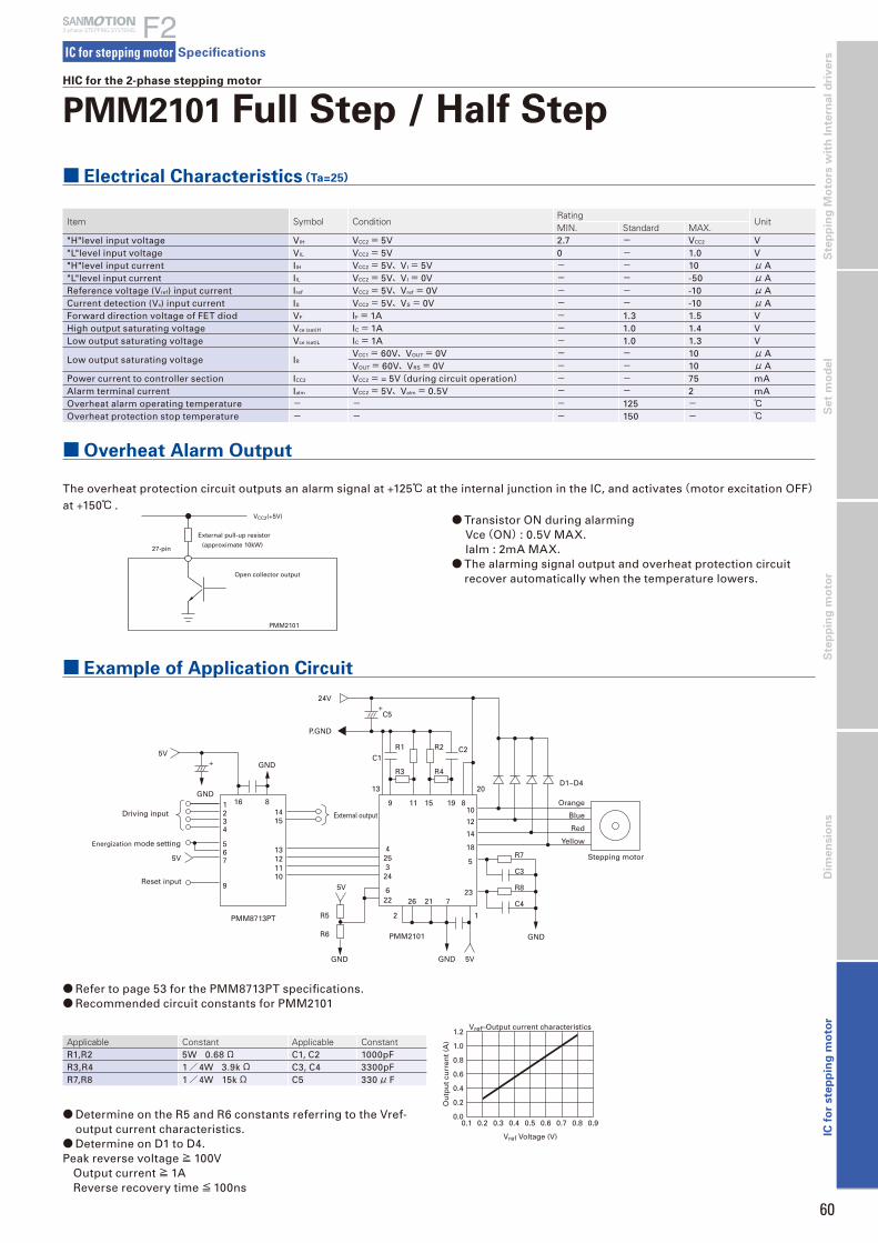
60
24V+
+
C2C1
R2R1
R3 R4
R5
R6
R7
P.GND
D1~D4
Orange
Blue
Red
Yellow
Stepping motor
C3
R8
C4
C5
5V
5V
5V
5V
GND
GND
GND
GND
GND
PMM2101
PMM8713PT 2 1
13 20
9 11 15 19 810
12
14
18
5
2372122
6
243254
26
1234
567
910111213
1514
816
Reset input
Driving input External output
Energization mode setting
Item Symbol ConditionRating
UnitMIN. Standard MAX.
"H"level input voltage VIH VCC2= 5V 2.7 - VCC2 V"L"level input voltage VIL VCC2= 5V 0 - 1.0 V"H"level input current IIH VCC2= 5V、VI= 5V - - 10 μA"L"level input current IIL VCC2= 5V、VI= 0V - - -50 μAReference voltage (Vref) input current Iref VCC2= 5V、Vref= 0V - - -10 μACurrent detection (Vs) input current IS VCC2= 5V、VS= 0V - - -10 μAForward direction voltage of FET diod VF IF= 1A - 1.3 1.5 VHigh output saturating voltage Vce (sat)H IC= 1A - 1.0 1.4 VLow output saturating voltage Vce (sat)L IC= 1A - 1.0 1.3 V
Low output saturating voltage IRVCC1= 60V、VOUT= 0V - - 10 μAVOUT= 60V、VRS= 0V - - 10 μA
Power current to controller section ICC2 VCC2= = 5V(during circuit operation) - - 75 mAAlarm terminal current Ialm VCC2= 5V、Valm= 0.5V - - 2 mAOverheat alarm operating temperature - - - 125 - ℃
Overheat protection stop temperature - - - 150 - ℃
Applicable Constant Applicable ConstantR1,R2 5W 0.68Ω C1, C2 1000pFR3,R4 1/4W 3.9kΩ C3, C4 3300pFR7,R8 1/4W 15kΩ C5 330μ F
■ Electrical Characteristics(Ta=25)
■ Overheat Alarm Output
The overheat protection circuit outputs an alarm signal at +125℃ at the internal junction in the IC, and activates(motor excitation OFF)
at +150℃ .
■ Example of Application Circuit
● Refer to page 53 for the PMM8713PT specifications.● Recommended circuit constants for PMM2101
● Determine on the R5 and R6 constants referring to the Vref-output current characteristics.
● Determine on D1 to D4.Peak reverse voltage≧ 100V Output current≧ 1A Reverse recovery time≦100ns
External pull-up resistor
Open collector output
(approximate 10kW)27-pin
PMM2101
VCC2(+5V) ● Transistor ON during alarming Vce(ON) : 0.5V MAX. lalm : 2mA MAX.● The alarming signal output and overheat protection circuit
recover automatically when the temperature lowers.
Vref–Output current characteristics
Vref Voltage (V)
0.1 0.2 0.3 0.4 0.5 0.6 0.7 0.8 0.90.0
0.2
0.4
0.6
0.8
1.0
1.2
Ou
tpu
t cu
rren
t (A
)
HIC for the 2-phase stepping motor
PMM2101 Full Step / Half Step
IC for stepping motor
2-phase STEPPING SYSTEMS
Specifications
IC f
or
ste
pp
ing
mo
tor
Dim
en
sio
ns
Ste
pp
ing
mo
tor
Se
t m
od
el
Ste
pp
ing
Mo
tors
wit
h I
nte
rna
l d
riv
ers

61
+0.2 0.4–0.05
+.008 (.016–.002 )+0.2
0.5–0.05+.008 (.02–.002 ) 2.9
(.11)
25.5
(1.0
0)
16(.6
3)
5.6
(.22
)
11(.43
)
9(.35)
4(.
16)
(.04
)1
221
[9]
(.35)
67(2.64)
60(2.36)
21x2=42(21x.08=1.68)
2–3.6(2–.14)
PMM2301
HIC for the 2-phase stepping motor
PMM2301Micro StepUnipolar
■ Characteristics
■Maximum Rating(Tc=25℃) ■ Recommended Operating Conditions(Ta=25℃)
・Sine wave driven micro-step driver.・The current detection resistor is incorporated.・MOSFET is used for the power driving circuit to reduce heating.・Totally packaged to reduce parts for the peripheral circuit.・Enables selection from the 5 various excitation modes by the external bit signal.
■ Dimensions[unit: mm(inch)]
Item Symbol Condition Rated value UnitSource voltage-1 VCC1 MAX. VCC2= 0V 52 VSource voltage-2 VCC2 MAX. With no signal 7 VInput voltage Vin MAX. Logic input terminal 7 VPhase current IOH MAX. 0.5sec, 1pulse, VCC1 applied 4 AOperating temperature on PCB
TC MAX. - 105 ℃
Junction temperature
Tj MAX. - 150 ℃
Conservation temperature
Tstg - -40 to 125 ℃
Item Symbol Condition Rated value UnitSource voltage-1 VCC1 With signal 10 to 45 VSource voltage-2 VCC2 With signal 5.0± 5% VInput voltage VIH - 0 to VCC2 VPhase current IOH Duty 50% 3 AClock frequency Clock - DC to 50 kHzWithstand voltage of phase driver
VDSS - 100 V
Pin No. Terminal name12. VCC2
13. VCC2
14. Clock15. CW/CCW16. Reset17. Return18. Enable19. M0I
20. M01
21. M02
22. GND
Pin No. Terminal name1. B2. B3. P.GND A4. P.GND B5. A6. A7. VCC2
8. Vref
9. Mode 110. Mode 211. Mode 3
Terminal name Function Functioning conditionVref Motor current setting input -
Clock Motor driving pulse inputMode 3 = “H” level : Operates at rising edgeMode 3 = “L” level : Operates at rising and falling edges
CW / CCW Motor rotation direction setting input“H” level = CW rotation“L” level = CCW rotation
Reset System reset Reset= "L"Return Forced return to phase origin Forced shift to the origin of the present energization phase with Return = “H”Enable Power OFF input Enable= "L"M0I Phase origin monitor output “L” level output at the phase origin.M01、M02 Monitor output on phase energization status Outputs level signal on the present phase energization status.
Phase coordinate
A phase B phase A phase B phase
M01 H L L HM02 L H L H
■ Each Terminal Function
IC for stepping motor
2-phase STEPPING SYSTEMS
Specifications
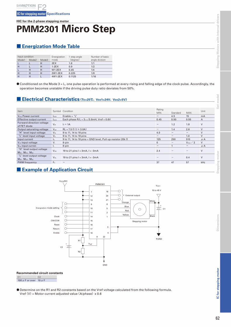
62
P.GND
C1
GND
710 to 45 V
VCC2(5V)
Vref
VCC1
R2
R1
C2
+
Return
Clook
Energization mode setting
External output
Stepping motor
PMM2301
CW/CCW
Reset
Endde
+
White
Black
Orange
Blue
Red
Yellow
12
13
9
10
11
14
15
16
17
18
8 22
4
3
1
2
5
6
21
20
19
■ Energization Mode Table
● Conditioned on the Mode 3 = L, one pulse operation is performed at every rising and falling edge of the clock pulse. Accordingly, the operation becomes unstable if the driving pulse duty ratio deviates from 50%.
Input condition Energization mode
1 step angle(degree)
Number of basic angle division Mode1 Mode2 Mode3
L L H 2EX 1.8 1/1H L H 1-2EX 0.9 1/2L H H W1-2EX 0.45 1/4H H H 2W1-2EX 0.225 1/8H H L 4W1-2EX 0.1125 1/16
■ Electrical Characteristics(Tc=25℃、Vcc1=24V、Vcc2=5V)
Item Symbol ConditionRating
UnitMIN. Standard MAX.
VCC2 Power current ICCO Enable = “L” - 4.5 15 mAEffective output current Ioave Each phase R/L = 3.5Ω /3.8mH, Vref = 0.6V 0.45 0.50 0.55 AForward direction voltage of FET diode
Vdf If= 1A - 1.2 1.8 V
Output saturating voltage Vsat RL = 7.5Ω(I≒ 3.0A) - 1.4 2.6 V“H” level input voltage VIH 9 to 11, 14 to 18 pins 4.0 - - V“L” level input voltage VIL 9 to 11, 14 to 18 pins - - 1.0 V
Input current IIL 9 to 11, 14 to 18 pins = GND level, Pull-up resistor 20kΩ 125 250 510 μAVref input voltage Vr 8-pin 0 - VCC2/ 2 VVref input curren Ir 8-pin - 1 - μA“H” level output voltage
M0I、M01、M02VOH 19 to 21 pins I = 3mA, I = -3mA 2.4 - - V
“L” level output voltage M0I、M01、M02
VOL 19 to 21 pins I = 3mA, I = -3mA - - 0.4 V
PWM frequency FC - 37 47 57 kHz
■ Example of Application Circuit
Recommended circuit constants
C1 C2100μ F or over 10μ F
● Determine on the R1 and R2 constants based on the Vref voltage calculated from the following formula. Vref(V) = Motor current adjusted value(A/phase)x 0.6
HIC for the 2-phase stepping motor
PMM2301 Micro Step
2-phase STEPPING SYSTEMS
IC for stepping motor Specifications
IC f
or
ste
pp
ing
mo
tor
Dim
en
sio
ns
Ste
pp
ing
mo
tor
Se
t m
od
el
Ste
pp
ing
Mo
tors
wit
h I
nte
rna
l d
riv
ers
63
Safety Consideration
The drivers and stepping motors are the products designed to be used for the general industrial devices.
When using those, pay enough attention to the following points.・Read thoroughly the Operation Manual prior to placement, assembly and/or operation in order to use the product properly.
・Refrain from modifying or processing the product in any way.
・Consult with the distributor or professional experts for placement or maintenance services of the product.
・In case of the following uses of the product, contact with us for the special care required to the operation, maintenance and
management such as multiplexing the system, installing an emergency electric generator set, or so forth.
1Use for the medical devices concerned with a fatal accident.
2Use for trains, elevators, and so forth that are likely to cause an accident resulting in injury, damage or death.
3Use in the computer system highly influential to the social life or the public systems.
4Use in other devices highly influential to maintaining the human safety or the public functions.
In addition to the above, consult with us for use in such a vibration environment as automobile or transportation.
Read the Operation Manual thoroughly prior to the use (placement, operation, maintenance and inspection) to put the product
in use properly.Make yourself knowledgeable and familiarize with the devices, safety issues and cautions before handling the product.
After reading the Operation Manual or the like, keep it in the place where the users can refer to whenever necessary.
This label is stuck near the high voltage part such as the electrically charged or cover-protected
section, warning that the place where it is likely to cause an electric shock.
This label is stuck on the place where the driver or stepping motor body should be easily
acknowledged, warning that it is likely to cause burns from high temperature.
This label is stuck near the GND terminals of the driver or stepping motor for which grounding is
required, suggesting that the terminals should be actually grounded.
This label is stuck for the driver or stepping motor to which the power source is applied in the voltage
exceeding the safety standard, drawing attention against the electric shock.
Indication by(Warning Label)on the productEither or all of the following indications are given by the Warning Labels depending on the type of the driver or stepping motor.
Safety ranks of the cautions
Following four ranks are provided.
Use propergroundingtechniques.
必ずアース線を 接続して下さい
危険
May Cause感電注意
electric shock
WARNING
Improper operations or use is most likely to result in serious injury or death.
Improper operations or use is likely to result in average or minor injury, or in property damage.
Indicates what shall not be done.
Indicates what shall be done.
DANGER
CAUTION
PROHIBITED
COMPULSORY
In spite of the cautions with the CAUTION label, it may cause serious results. Eitherthe contents of the labels is describing important cautions to be followed inevitably.
CAUTION

64
18. Mount the product on an incombustible material such as metal. Doingotherwise may cause fire.
19. Confirm the rotating direction before connecting with the mechanicaldevice. Failure to do so may cause injury or a breakdown.
20. Do not touch the motor output spindle (including the key slot and gears) with a barehand. Doing so may cause injury.
<Operation>21. The stepping motor is not equipped with any protective device. Take
protective measures using an over-current protective relay, a ground faultinterrupter, a protective device from excess temperature, and an emergencystopping device. Failure to do so may cause injury or fire.
22. Do not touch the product for a period after the power is on or has been turnedoff, since the driver and stepping motor remain in the high temperature. Doingso may cause burns. Especially the temperature rises considerably of thestepping motor depending on the operating conditions. Use the motor on thecondition so that its surface temperature becomes 100°C or under.
23. Stop the operation immediately when an emergency occurs. Failure to do so maycause an electric shock, injury or fire.
24. Do not change adjustment to an extreme, for such a change results in the unstableoperation. Doing so may cause injury.
25. When conducting the trial operation, make the stepping motor fixed firmly, andconfirm the operation by disconnecting with the mechanical system beforeconnecting with it. Failure to do so may cause injury.
26. When the alarm has been activated, eliminate the cause and ensure thesafety to resume operation. Failure to do so may cause injury.
27. When the electric power recovers after the momentary interruption, do notapproach the devices because the system may re-start operation by itself.(Set the system so as to secure the safety even when it re-start on suchoccasion.) Failure to do so may cause injury.
28. Confirm that the electric power supply is all proper conforming to thespecifications. Failure to do so may cause a trouble.
29. The brake mechanism of the motor with the electro-magnetic brake is tohold the movable section and the motor position. Do not use it as a safetymeasure, or doing so may cause the breakdown of the system.
30. Fix the key firmly when operating the motor with key individually. Failure todo so may cause injury.
<Maintenance services>31. Be careful when performing maintenance services or inspection about the
temperature which rises highly in the driver and stepping motor frame.Failure to do so may cause burns.
32. It is recommended to replace the electrolytic condenser of the driver with anew one for securing the preventive measure after using for 5 years, theexpected life in the average 40°C. The expected life of the fuse
is 10 years in the average 40°C. Thus, the periodical replacement is recommended.
33. Contact with us for repair. If the product is disassembled by the user, it mayput it out of action.
<Transportation>34. Handle the product with care during transportation so as to prevent from the
danger such as a tumble or a turnover.
35. Do not hold with the cable or the motor spindle. Doing so may cause atrouble or injury.
<Retirement>36. When scrapping the driver or stepping motor, treat it for the general
industrial waste.
<Storage>1. Avoid the place exposed to rain or water drops, or in an environment with
hazardous gas or liquid for storing the product. Failure to do so may cause atrouble.
<Maintenance services>2. Do not assemble or repair the product. Doing so may cause fire or an
electric shock.
<General matters>3. Do not remove the rating plate.
<Storage>1. Store the product within the specified conservation temperature and
humidity in the place not exposed to the sun beam.
2. If the driver has been stored for a long period (3 years or longer for a guide),consult with us. The capacitance may have decreased with the electrolyticcondenser due to the long period storage, and it may cause a trouble.
<Operation>3. Install an external emergency stop circuit to turn the power off for the
instant halt of operation.
4. Put the product into operation in the specified ambient temperature andhumidity.
<Transportation>5. Excess loading of the product on the carrier may cause the load to fall in
pieces. Follow the instructions given outside the package.
<General matters>1. Do not use the product in an explosive, flammable or corrosive atmosphere, watery
place or near a combustible material. Doing so may cause injury or fire.
2. Have a person with expert knowledge for performing the transportation,placement, wiring, operation, maintenance or inspection of the product.Without such knowledge, it may cause an electric shock, injury or fire.
3. Do not work for wiring, maintenance servicing or inspection with the electricpower on. Perform either of those five minutes after turning the power off,or otherwise, it may cause an electric shock.
4. When the protective functions of the product is activated, turn the power offimmediately and eliminate the cause. If continuing the operation withouteliminating the cause, the product may operate improperly and cause injuryor a breakdown of the system devices.
5. Stepping motor may run out of order at the operating and stoppingoccasions, depending on the magnitude of the load. Put the product into useafter confirming with the adequate trial test operation in the maximum loadconditions that the product performs reliable operation. Doing otherwisemay cause a breakdown of the system. (Should the product run out of orderin the use to drive upward/downward, it may cause a fall of the load.)
6. Do not touch the internal parts of the driver. Doing so may cause an electricshock.
<Wiring>7. Do not connect the stepping motor directly with the commercial power
outlet. Doing so may cause an electric shock, injury or fire. The power shallbe supplied to the stepping motor through the driving circuit.
8. Use the electric power source within the rated input voltage. Usingotherwise may cause fire or an electric shock.
9. Connect the driver and stepping motor to the ground. Using withoutgrounding may cause an electric shock.
10. Do not harm, forcibly put a stress, or load a heavy article on the cable or getit caught between the articles. Doing so may cause an electric shock.
11. Perform wiring with the power cable as instructed by the wiring diagram orthe Operation Manual. Doing otherwise may cause an electric shock or fire.
<Operation>12. Be sure not to touch the rotating part of the stepping motor during its
operation. Touching it may cause injury.
13. Neither reach or touch the electric terminals while electric power is on.Doing so may cause an electric shock.
14. Never disconnect any of the connectors while electric power is on. Doing so maycause an electric shock and corruption.
<General matters>1. Prior to placement, operation, maintenance servicing or inspection, be sure
to read the Operation Manual and follow the instructions to perform those.Failure to follow the instructions may cause an electric shock, injury or fire.
2. Do not use the driver or the stepping motor outside the specified conditions.Doing so may cause an electric shock, injury or fire.
3. Do not insert a finger or a thing into the opening of the product. Doing so may causean electric shock, injury or fire.
4. Do not use the damaged driver or stepping motor. Doing so may causeinjury, fire or the like.
5. Use the driver and stepping motor in the designated combination. Usingotherwise may cause fire or a trouble.
6. Be careful that the temperature rises in the operating driver, stepping motoror peripheral devices. Failure to be careful may cause a burn.
<Unpacking>7. Unpack while confirming the ceiling. Failure to do so may cause injury.
8. Confirm if the product is the one having been ordered. Installing an incorrectproduct may cause a breakdown.
<Wiring>9. Do not perform measurement of the insulation resistance or withstand
insulation voltage of the product. Doing so may cause a breakdown. Instead,contact with us for such inspection.
10. Perform wiring conforming to the technical standards of electric facility orthe internal rule. Doing otherwise may cause burning or fire.
11. Ensure that wiring has been correctly done. Operating without correctwiring may cause the stepping motor to run out of control and result ininjury.
12. Take insulation process for the attached condenser or the external resistanceconnection terminals. Failure to do so may cause an electric shock.
<Placement>13. Do not climb or attach a heavy article on the product. Doing so may cause
injury.
14. Neither block nor stuff the aspiration/exhaust vent with a foreign particle.Doing so may cause fire.
15. Follow the instructions for the direction to place. Failure to do so may causea trouble.
16. Keep a distance as instructed by the Operation Manual for the driver fromthe inner surface of the control console or other devices. Failure to do somay cause a trouble.
17. Place the product with a great care so as to prevent from the danger such asa tumble or a turnover.
DANGER CAUTION
PROHIBITED
COMPULSORY


1 Name of target equipment Equipment name, category (transport, processing, test, other)
9 Encoder type
Encoder type specified ( yes / no )
Yes:(incremental , optical absolute , optical absolute with incremental function, resolver absolute)
Resolution( )
2 Name of servo axis Axis name, axial mechanism (horizontal/vertical), brake mechanism (yes/no)
3 Current condition of above axis Manufacturer Name ( ) Series Name ( ) Motor Capacity ( ) Hydraulic, Mechanical, or New System ( )
4 Positioning accuracy ± mm・± μm
5 Operation pattern
Accelerationα:__G・___[m/s2]
Feeding SpeedV:____[m/s]
Feeding
Speed
[m/sec]
【Reference formula】【1G=9.8[m/s2]、1[m/s2]≒0.1G】【α[m/s2]=V[m/sec]÷t1[sec]】【D[m]=V[m/sec]×(t1+t2)[sec]】Moving DistanceD:___[m]
(Stroke)
6 MechanismBall-screw/screw-rotation type (horizontal), ball-screw/nut-rotation type (horizontal),
rack and pinion (horizontal), belt/chain (horizontal), rotary table, roll feed, instability
7 Mechanical structure
WT(table mass) kg WL(work mass) kg WA(mass of other drive parts) kg
WR(rack mass) kg WB(belt/chain mass) kg WC(counterbalance mass) kg
Fa(external force axial direction) N Fb(ball-screw preload) N T(roll pushing force) N
Dr1(drive-side roll diameter) mm Dr2(follower-side roll diameter) mm
Lr1(drive-side roll length) mm Lr2(follower-side roll length) mm G(reduction ratio)JG(speed-reducer inertia) kg・m2 JC(coupling inertia) kg・m2
JN(nut inertia) kg・m2 JO(other motor-axis conversion inertia) kg・m2
Db(ball-screw diameter) mm Lb(ball-screw axial length) mm Pb(ball -screw lead) mm
Dp(pinion/pulley diameter) mm Lp(pinion axial length) mm tp(pully thickness) mm
Dt(table diameter) mm Dh(table-support dianeter) mm LW(load shift from axis) mm
Ds(table shaft diameter) mm Ls(table shaft length) mm
ρ(specific gravity of ball-screw/pinion/pulley/table-shaft material) kg・cm3
μ(friction coefficient between sheet and shiliding-surface/support-section/roll) ρ1(specific gravity of roll-1 material) kg/cm3
ρ2(specific gravity of roll-2 material) kg/cm3 κ(internal friction coefficient of preload nut)η(mechanical efficiency) JL(load inertia of motor-axis conversion) kg・m2
TF(friction torque of motor axis conversion) N・m Tu(imbalance torque of motor axis conversion) N・m
0 Input format Position , velocity , torque , other ( )
A Host equipment (controller) Sequencer , laptop , customer-developed product , Sanyo dennki-provided , other ( )
C Estimated production Single product: ( ) units/mouth ( ) units/year
D Development schedule Prototype period: ( )Year ( ) Month Production period: ( )Year ( ) Month
Various measures Related documentation ( already submitted; send later by mail) Visit/PR desired ( yes / no ) Meeting desired ( yes / no )E
FMiscellaneous
(questions, pending problems,
unresolved issues, etc.)
B Usage environment and other requirements Cutting , clean-room use , anti-dust measures , other ( )
8 Speed reducer Customer-provided ( / )・Sanyo denki standard(planet/spur/no-backlash-planet / ) other( / )
Item Contents
Time
Inquiry Check Sheet For more information regarding any products or services described here in, please contact your nearest office listed on the back of this catalog.
Date:To SANYO DENKI Co.,LTD.
Company:
Department:
Name:
Tel: FAX:
E-mail:

CATALOG No. 832-6 ’09.3.N
*For any question or inquiry regarding the above, contact our Sales Department.
Cautions
■ Precautions For Adoption
Failure to follow the precautions on the right may cause moderate injury and property damage, or in some circumstances, could lead to a serious accident.Always follow all listed precautions.
http://www.sanyodenki.co.jp
Phone: +81 3 3917 5157
Phone: +49 6196 76113 0
Phone: +82 2 773 5623
Phone: +86 21 6235 1107
Phone: +1 310 783 5400
Phone: +33 1 48 63 26 61
Phone: +886 2 2511 3938
Phone: +852 2312 6250
Phone: +65 6223 1071
468 Amapola Avenue Torrance, CA 90501 U.S.A.
1-15-1, Kita-Otsuka, Toshima-ku, Tokyo 170-8451, Japan
P.A. Paris Nord ll 48 Allee des Erables-VILLEPINTE BP.57286 F-95958 ROISSY CDG Cedex France
Frankfurter Strasse 63-69 65760 Eschborn Germany
10 Hoe Chiang Road #14-03A/04 Keppel Towers Singapore 089315
Room 2116, Bldg B, FAR EAST INTERNATIONAL PLAZA, No.317 XianXia Rd., Shanghai 200051 China
Room 1208, 12F, No.96 Chung Shan N, Rd., Sec.2, Taipei 104, Taiwan, R.O.C.
Room 2305, 23/F, South Tower, Concordia Plaza, 1 Science Museum Rd., TST East, Kowloon, Hong Kong
9F 5-2, Sunwha-dong Jung-gu Seoul, 100-130, Korea
Cautions
The names of companies and/or their products specified in this catalogue are the trade names, and/or trademarks and/or registered trademarks of such respective companies.*Remarks : Specifications Are SubjectTo Change Without Notice.


