
1/8/2007 - L3 Data Path Design Copyright 2006 - Joanne DeGroat, ECE, OSU 1
ALUs and Data PathsSubtitle: How to design the data path of a processor.

1/8/2007 - L3 Data Path Design
Copyright 2006 - Joanne DeGroat, ECE, OSU 2
Lecture overview General Data Path Design Design of a multifunction ALU

1/8/2007 - L3 Data Path Design
Copyright 2006 - Joanne DeGroat, ECE, OSU 3
Design of ALUs and Data Paths Objective: Design a General Purpose Data
Path such as the datapath found in a typical computer.
A Data Path Contains: Registers – general purpose, special purpose Execution Units capable of multiple functions

1/8/2007 - L3 Data Path Design
Copyright 2006 - Joanne DeGroat, ECE, OSU 4
ALU Operations (integer ALU) Add (A+B) Add with Carry (A+B+Cin) Subtract (A-B) Subtract with Borrow (A-B-Cin) [Subract reverse (B-A)] [Subract reverse with Borrow (B-A-Cin)] Negative A (-A) Negative B (-B) Increment A (A+1) Increment B (B+1) Decrement A (A-1) Decrement B (B-1) Logical AND Logical OR Logical XOR
Not A Not B A B Multiply Step or Multiply Divide Step or Divide Mask Conditional AND/OR (uses
Mask) Shift Zero

1/8/2007 - L3 Data Path Design
Copyright 2006 - Joanne DeGroat, ECE, OSU 5
A High Level Design
From Hayes textbook on architecture.
1/8/2007 - L3 Data Path Design
Copyright 2006 - Joanne DeGroat, ECE, OSU 6
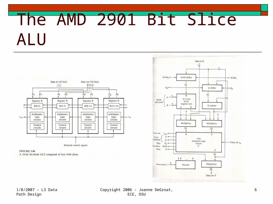
The AMD 2901 Bit Slice ALU

1/8/2007 - L3 Data Path Design
Copyright 2006 - Joanne DeGroat, ECE, OSU 7
The Architecture
1/8/2007 - L3 Data Path Design
Copyright 2006 - Joanne DeGroat, ECE, OSU 8
Arithmetic Logic Circuits The Brute Force Approach
A more modern approach
1/8/2007 - L3 Data Path Design
Copyright 2006 - Joanne DeGroat, ECE, OSU 9
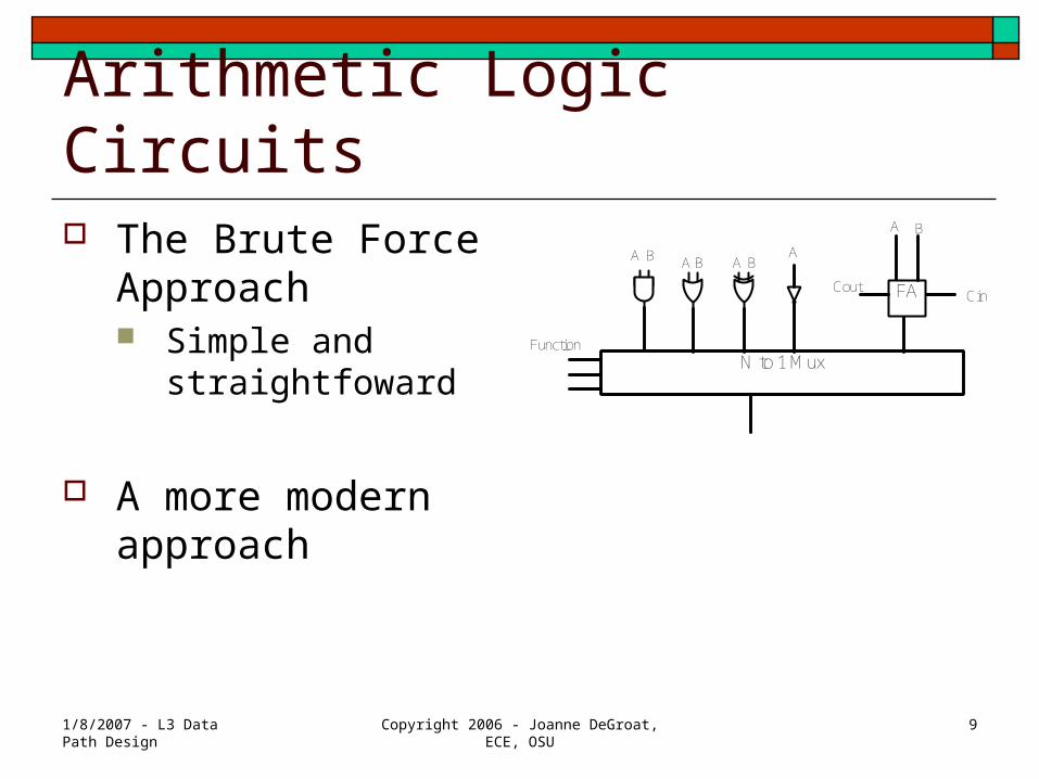
Arithmetic Logic Circuits The Brute Force
Approach Simple and
straightfoward
A more modern approach
N to 1 Mux
FA
Function
CoutCin
A B A AA
A B
BB
1/8/2007 - L3 Data Path Design
Copyright 2006 - Joanne DeGroat, ECE, OSU 10
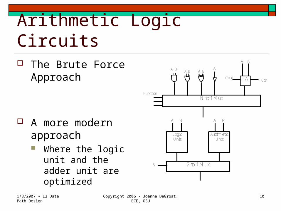
Arithmetic Logic Circuits The Brute Force
Approach
A more modern approach Where the logic unit
and the adder unit are optimized
N to 1 Mux
FA
Function
CoutCin
A B A AA
A B
BB
LogicUnit
ArithmeticUnit
2 to 1 Mux
A AB B
S
1/8/2007 - L3 Data Path Design
Copyright 2006 - Joanne DeGroat, ECE, OSU 11
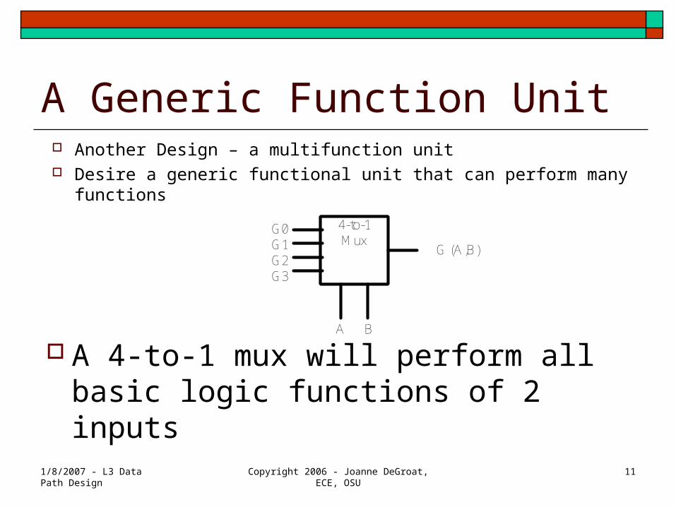
A Generic Function Unit Another Design – a multifunction unit Desire a generic functional unit that can perform many functions
A 4-to-1 mux will perform all basic logic functions of 2 inputs
G (A,B)
BA
4-to-1Mux
G0G1G2G3

1/8/2007 - L3 Data Path Design
Copyright 2006 - Joanne DeGroat, ECE, OSU 12
Low level implementation
G0
G1
G2
G3
A B B’A’
G(A,B
At the implementationLevel the design can beWith transmission gatesVery important for VLSI implementation
Implementation has a totalOf 16 transistors.
Could also use NAND NOR implementation.
1/8/2007 - L3 Data Path Design
Copyright 2006 - Joanne DeGroat, ECE, OSU 13
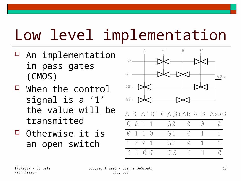
Low level implementation An implementation in
pass gates (CMOS) When the control
signal is a ‘1’ the value will be transmitted
Otherwise it is an open switch
G0
G1
G2
G3
A B B’A’
G(A,B
A B A’ B’ G(A,B) AB A+B AxorB
0 0 1 1 G0 0 0 0
0 1 1 0 G1 0 1 1
1 0 0 1 G2 0 1 1
1 1 0 0 G3 1 1 0

1/8/2007 - L3 Data Path Design
Copyright 2006 - Joanne DeGroat, ECE, OSU 14
Lets look at Binary Addition We can use this generic function
unit construct a generic ALU. For Binary Addition consider the
following: SUMi = Ai xor Bi xor Ci
Ci+1 = Ai Bi + Ai Ci + Bi Ci
A B Cin Sum Cout
0 0 0 0 00 0 1 1 00 1 0 1 00 1 1 0 11 0 0 1 01 0 1 0 11 1 0 0 11 1 1 1 1
1/8/2007 - L3 Data Path Design
Copyright 2006 - Joanne DeGroat, ECE, OSU 15
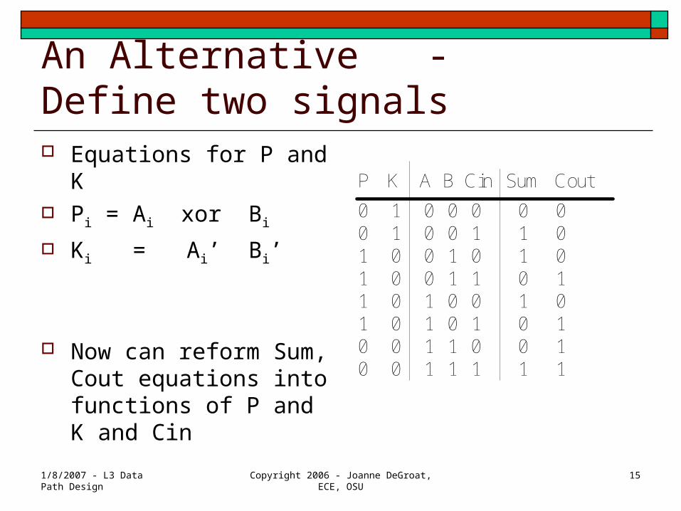
An Alternative - Define two signals Equations for P and K Pi = Ai xor Bi
Ki = Ai’ Bi’
Now can reform Sum, Cout equations into functions of P and K and Cin
P K A B Cin Sum Cout
0 1 0 0 0 0 00 1 0 0 1 1 01 0 0 1 0 1 01 0 0 1 1 0 11 0 1 0 0 1 01 0 1 0 1 0 10 0 1 1 0 0 10 0 1 1 1 1 1

1/8/2007 - L3 Data Path Design
Copyright 2006 - Joanne DeGroat, ECE, OSU 16
New functions Using these definitions of P and K SUMi = Pi xor Ci
Ci+1 = Pi Ci + Pi’ Ki’ = Pi Ci + AiBi
You can use the generic functional blocks to generate P and K and then select the correct function for final output

1/8/2007 - L3 Data Path Design
Copyright 2006 - Joanne DeGroat, ECE, OSU 17
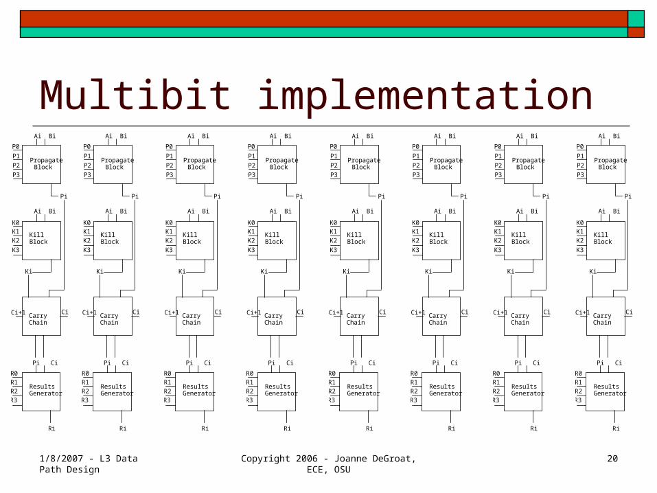
A bit slice of the ALU Slice starts out with a generic unit
which can produce any function of inputs Ai and Bi to produce Pi
Need another to produce Ki (kill block)
And a 3rd to generate the result (results generator block)
And also need a dedicated unit to compute the carry out, the Ci+1 term
P0
P1
P2
P3
Pi
K0
K1
K2
K3
Ki
R0
R1
R2
R3
Ri
CiCi+1
Propagate Block
Kill Block
Carry Chain
Results Generator
Ai Bi
Ai Bi
Pi Ci

1/8/2007 - L3 Data Path Design
Copyright 2006 - Joanne DeGroat, ECE, OSU 18
Generation of the carry out Ci+1 = Pi Ci + Pi’Ki’ The carry chain is the
critical path for arithmetic operations.
A simple ripple carry circuit is shown here for the slice
Actual implementation depend on the technology in which implemented.
P
Cin
K
Cout
1/8/2007 - L3 Data Path Design
Copyright 2006 - Joanne DeGroat, ECE, OSU 19
Carry chain implementation CMOS – Manchester carry chain using
precharge pulldown logic works well. ECL – Carry look-ahead circuitry works well
as ECL allows for large fan-in wired OR gates.
1/8/2007 - L3 Data Path Design
Copyright 2006 - Joanne DeGroat, ECE, OSU 20
Multibit implementationP0
P1
P2
P3
Pi
K0
K1
K2
K3
Ki
R0
R1
R2
R3
Ri
CiCi+1
Propagate Block
Kill Block
Carry Chain
Results Generator
Ai Bi
Ai Bi
Pi Ci
P0
P1
P2
P3
Pi
K0
K1
K2
K3
Ki
R0
R1
R2
R3
Ri
CiCi+1
Propagate Block
Kill Block
Carry Chain
Results Generator
Ai Bi
Ai Bi
Pi Ci
P0
P1
P2
P3
Pi
K0
K1
K2
K3
Ki
R0
R1
R2
R3
Ri
CiCi+1
Propagate Block
Kill Block
Carry Chain
Results Generator
Ai Bi
Ai Bi
Pi Ci
P0
P1
P2
P3
Pi
K0
K1
K2
K3
Ki
R0
R1
R2
R3
Ri
CiCi+1
Propagate Block
Kill Block
Carry Chain
Results Generator
Ai Bi
Ai Bi
Pi Ci
P0
P1
P2
P3
Pi
K0
K1
K2
K3
Ki
R0
R1
R2
R3
Ri
CiCi+1
Propagate Block
Kill Block
Carry Chain
Results Generator
Ai Bi
Ai Bi
Pi Ci
P0
P1
P2
P3
Pi
K0
K1
K2
K3
Ki
R0
R1
R2
R3
Ri
CiCi+1
Propagate Block
Kill Block
Carry Chain
Results Generator
Ai Bi
Ai Bi
Pi Ci
P0
P1
P2
P3
Pi
K0
K1
K2
K3
Ki
R0
R1
R2
R3
Ri
CiCi+1
Propagate Block
Kill Block
Carry Chain
Results Generator
Ai Bi
Ai Bi
Pi Ci
P0
P1
P2
P3
Pi
K0
K1
K2
K3
Ki
R0
R1
R2
R3
Ri
CiCi+1
Propagate Block
Kill Block
Carry Chain
Results Generator
Ai Bi
Ai Bi
Pi Ci
1/8/2007 - L3 Data Path Design
Copyright 2006 - Joanne DeGroat, ECE, OSU 21
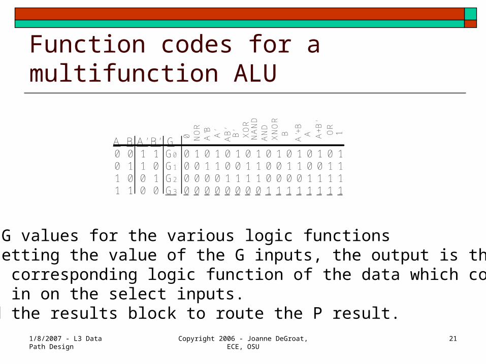
Function codes for a multifunction ALU
The G values for the various logic functionsBy setting the value of the G inputs, the output is the corresponding logic function of the data which comes in on the select inputs.Need the results block to route the P result.
A B A’ B’ G0 0 1 1 G0 0 1 0 1 0 1 0 1 0 1 0 1 0 1 0 10 1 1 0 G1 0 0 1 1 0 0 1 1 0 0 1 1 0 0 1 11 0 0 1 G2 0 0 0 0 1 1 1 1 0 0 0 0 1 1 1 11 1 0 0 G3 0 0 0 0 0 0 0 0 1 1 1 1 1 1 1 1
NO
RA
’B A’
AB
’
0 B’
XO
R
AN
DX
NO
RB
A’+
B
NA
ND
A A+
B’
OR
1
1/8/2007 - L3 Data Path Design
Copyright 2006 - Joanne DeGroat, ECE, OSU 22
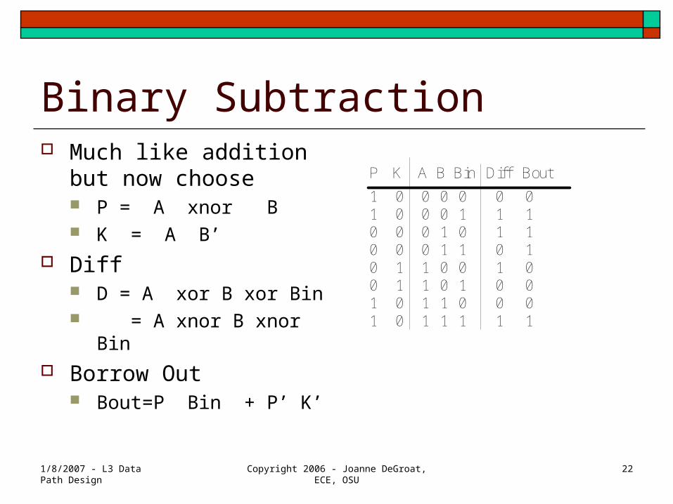
Binary Subtraction Much like addition but
now choose P = A xnor B K = A B’
Diff D = A xor B xor Bin = A xnor B xnor Bin
Borrow Out Bout=P Bin + P’ K’
P K A B Bin Diff Bout
1 0 0 0 0 0 01 0 0 0 1 1 10 0 0 1 0 1 10 0 0 1 1 0 10 1 1 0 0 1 00 1 1 0 1 0 01 0 1 1 0 0 01 0 1 1 1 1 1

1/8/2007 - L3 Data Path Design
Copyright 2006 - Joanne DeGroat, ECE, OSU 23
The codes to have the ALU work Consider as we
go to the sliced ALU
Logic function done in the P generic unit
Math uses all the blocks
Function P K R Cin
A 12 --- 12 ---
A and B 8 -- 12 ---
OR 14 --- 12 ---
A + B + Cin
6 1 6 Cin
A+B 6 1 6 0
Incr A 12 3 6 1
A – B 9 4 9 0 or Bin

1/8/2007 - L3 Data Path Design
Copyright 2006 - Joanne DeGroat, ECE, OSU 24
Multibit implementationP0
P1
P2
P3
Pi
K0
K1
K2
K3
Ki
R0
R1
R2
R3
Ri
CiCi+1
Propagate Block
Kill Block
Carry Chain
Results Generator
Ai Bi
Ai Bi
Pi Ci
P0
P1
P2
P3
Pi
K0
K1
K2
K3
Ki
R0
R1
R2
R3
Ri
CiCi+1
Propagate Block
Kill Block
Carry Chain
Results Generator
Ai Bi
Ai Bi
Pi Ci
P0
P1
P2
P3
Pi
K0
K1
K2
K3
Ki
R0
R1
R2
R3
Ri
CiCi+1
Propagate Block
Kill Block
Carry Chain
Results Generator
Ai Bi
Ai Bi
Pi Ci
P0
P1
P2
P3
Pi
K0
K1
K2
K3
Ki
R0
R1
R2
R3
Ri
CiCi+1
Propagate Block
Kill Block
Carry Chain
Results Generator
Ai Bi
Ai Bi
Pi Ci
P0
P1
P2
P3
Pi
K0
K1
K2
K3
Ki
R0
R1
R2
R3
Ri
CiCi+1
Propagate Block
Kill Block
Carry Chain
Results Generator
Ai Bi
Ai Bi
Pi Ci
P0
P1
P2
P3
Pi
K0
K1
K2
K3
Ki
R0
R1
R2
R3
Ri
CiCi+1
Propagate Block
Kill Block
Carry Chain
Results Generator
Ai Bi
Ai Bi
Pi Ci
P0
P1
P2
P3
Pi
K0
K1
K2
K3
Ki
R0
R1
R2
R3
Ri
CiCi+1
Propagate Block
Kill Block
Carry Chain
Results Generator
Ai Bi
Ai Bi
Pi Ci
P0
P1
P2
P3
Pi
K0
K1
K2
K3
Ki
R0
R1
R2
R3
Ri
CiCi+1
Propagate Block
Kill Block
Carry Chain
Results Generator
Ai Bi
Ai Bi
Pi Ci


