
1 2 3 4
5 6 7 8
27/1
.06
6/0.
24
40/1
.57
1 2 3 4
5 6 7 8
6/0.
24
WiringCâblageVerkabelungCableadoCablaggioLigações
DeutschFrançaisEnglish
ItalianoEspañol Português
DimensionsEncombrementsAbmessungenDimensionesDimensioniDimensões
mm/in
AccessoriesAccessoiresZubehörAccesoriosAccessoriAcessórios
XY2-AU1 X
XY2-AU1 XY2-AU2
36/1.41
46/1.81
54/2.13
58/2.28
174/
6.85
86/3
.38
36/1.41
46/1.81 58/2.28
174/
6.85
86/3
.38
9/0.
35
Ø13,5/0.53 Ø13,5/0.53
54/2.13
0,5 Nm3.9 Lb.in
4 Nm35 Lb.in
XCS-Z01 + XY2-AZ2
XCS-E
1,2 Nm10 5 Lb i
mm/in
W91
6343
7801
11 A
04 1
/2XY2-AU
Enabling switchCommande de validationZustimmungsschalterMando de validación
Comando de validação
10. .in
XY2-AZ3
Replacing the coverRemplacement du couvercleAustausch der Abdeckung
Sostituzione del coperchioSubstituição da tampa
EN ISO 12100,
Quando il comando di validazione è correttamente
éPreventa individueràdelcomando di validazione.
ñ úvigentes: IEC 60947,
á
ó
XPSVC, segúí
la norma EN954-1. El mó ácortocircuitos en el cableado del mando de validación.
EN ISO 12100, EN 60204, a fimç áquinas
es.
ão
ó á os curto-circuitos nacablagem do comando de validação.
été conçus d’après les normes en
é é ééglages.
connectée au module de sécuritésenté, alors la
éé
c blage de la commande de validation.
with the standards in effect : IEC 60947,12100,operators in thedevelopment and adjustment phases.
Preventa safety module XPSVC according to the
standards EN 954-1 is reached. The Preventa modulewill detect short circuits in the cabeling of the enabling
Die Geräte wurden gemäß
ä ür den Maschinen-
ß des Zustimmungsschalters anden Ü
äß EN 954-1 erreicht. Der Üßüberwachung der
Anschlußleitungen zu den Kontakten des dreistufigenZustimmungsschalters.
For reasons of safety the hand-held enabling switches must only beoperated manually.
ées de commande de validation doivent exclusivement êtreactionnées manuellement sous peine de danger pour l’opérateur.
ausschliesslich durch die manuele Betätigung des qualifiziertenFachpersonals erfolgen.Los mandos de validación deben ser accionados exclusivamente deforma manual bajo riesgo de peligro para el operario.
dall’operatore.Os punhos de validação só podem ser operados manualmente, devido a
XY2-AZ1
mm/in
53/2
.09
81/3.19
84/3.31
50/1.97
20/0
.79
2 Ø5,3/0.20
W916343780111A04
163437801A55 04 11/2005
XCS-Z11 + XY2-AZ2
XCS-P
XCS-T
10.5 Lb.in 1,2 Nm
B e i A n w e n d u n g d e s S c h a l t u n g s -vorschlags wird durch Entnahme desZus t immungsscha l te rs aus dem
•••d i e g e f äun te rb rochen , d i e Funk t i on des
üssel-schalter XB4G•••gewäZustimmungsschalters werden nachder Umschaltung durch das XPS-VCüberwacht.
(1)
(2)
- Validation- Validation- Zustimmung
- Validación- Attivazione- Validação
- Stop- Arrêt- Stopp
- Parada- Arresto- Paragem
- Gripping stop- Arrê- Stopp durch Zwangstrennung- Parada por crispamiento
- Paragem por crispação
0-1
1-2
1-02-0
Control diagram / Schéma de la commande / Befehlsschaltbild /
Contact status / Etat des contacts / Kontaktzustand / Estado de los contactosStato dei contatti / Estado dos contactos
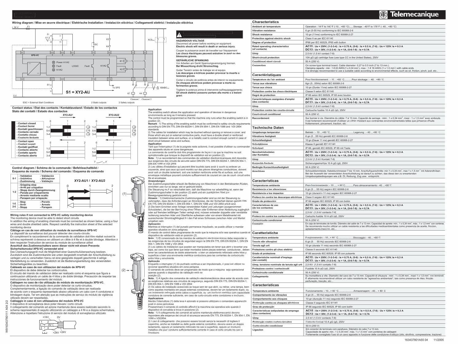
Wiring diagram / Mise en œuvre électrique / Elektrische Installation / Instalación eléctrica / Collegamenti elettrici / Instalação eléctrica
HAZARDOUS VOLTAGEDisconnect all power before working on equipment.Electric shock will result in death or serious injury.
équipementé îner la mort ou des
ät Spannungsversorgung trennen.
Quitar TensióLas descargas eléctricas pueden provocar la muerte olesiones graves.
Cortar o circuito de potência antes de intervir no equipamento.Os choques eléferimentos graves.
Gli shock elettrici possono portare alla morte o a lesionigravi.
DANGER / WARNUG / PELIGROPERIGO / PERICOLO
- Contact closed- Contact fermé
- Contacto cerrado- Contatto chiuso- Contacto fechado
- Contact ouvert
- Contacto abierto- Contatto aperto- Contacto aberto
XY2-AU1 XY2-AU2
0 1 2 0 1 2
0 1 20 1 2
1-25-63-4
1-25-63-4
1-25-63-4
1-25-63-4
7 8
XY2-AU1 / XY2-AU2
0 1 2
ApplicationThe enabling switch allows the application and operation of devices in dangerousenvironments as long as it remains pressed.The control must be programmed so that the machine only runs when the enabling switch is inposition (2).Remark : 1) The wiring of the enabling switch must be conformed to safety circuits requirementskaccording to DIN EN 775, DIN EN 60204-1, DIN EN 954-1, DIN EN 1088 and VDI 2854standards2) The cables for installation which may be touched without opening or remove a cover, andthose which are put on external conductive parts, must have a double shield or reinforcedinsulation between wires and surface, or a metallic coat to conduct enough current in case of short circuit between wires and surface.Application
ée reste actionnédes appareils situé
ô ê ée de façon àopéNota électromé épondreaux exigences des circuits de sécurité selon DIN EN 775, DIN EN 60204-1, DIN EN 954-1,DIN EN 1088 et VDI 28542) Les câ ê é à ouvrir ou enlever un
é èces é ères conductrices, doiventavoir soit un double isolement, soit une isolation renforcée entre fils et surface, soit uneenveloppe métallique pouvant conduire suffisamment de courant en cas de court- circuit entrefils et enveloppe.Anwendungen
üsten,ü
Die Steuerung muß ß äätzlicher Start zur
Hinweisäß DIN
EN 775, DIN EN 60204-1, DIN EN 954-1, DIN EN 1088 und VDI 2854 erfüllt sind.
ü Ö
äähigkeit fü
umgeben sein.AplicaciónMientras el interruptor (1) del punado permanece impulsado, se puede utilizar o mandar
áquina sólo sea operativa cuando el
Nota ón electromecánicos debe responder aú
954-1, DIN EN 1088 y VDI 2854
tapa, así como los que tiene que estar montados sobre piezas externas conductoras , deben
superficie o bien una envolvente metálica conductora para las corrientes de cortocircuito
Aplicaçãoé possível utilizar ou
accionar aparelhos situados em zona perigosa.á
ção está na
ção dos comandos de validaçã ânicos deve estar de acordo comç
ção acessíç
um isolamento reforç ície, ou um invólucro metálico com capacidadecondutora de corrente suficiente, em caso de curto-circuito entre condutores e invólucro.ApplicazioneMentre l'interruttore (1) della leva è azionato si possono utilizzare o comandare apparecchiposti in zone pericolose.Programmare il comando di controllo affinché la macchina sia operativa solo quando ildispositivo di convalida si trova in posizione (2).Nota : 1) Il collegamento dei comandi ad azione mantenuta elettromeccanici devonorispondere alle esigenze dei circuiti di sicurezza secondo EN 775, EN 60204-1, EN 954-1, EN1088 e VDI2854.2) I cavi di collegamento che possono essere toccati senza la necessità di togliere il
isolamento, oppure un isolamento rinforzato tra cavi e superficie, oppure un involucrometallico che puo' condurre sufficientemente corrente in caso di corto circuito tra cavi el'involucro.
Wiring rules if not connected to XPS-VC safety monitoring deviceThe monitoring device must be able to detect short circuits.In addition the wiring of enabling channels must be connected as shown below, using a four
monitoring device
étecter des courts-circuits.é être ré é suivant le
sché ésenté ci-dessous en utilisant un câble à 4 fils et à àbien respecter l'instruction de service du module de surveillance utilisé.Anschluß des Zustimmschalters wenn dieser nicht mit einem Preventa
Das Überwachungsgerät muß die Mö ßüberwachung besitzen.Zusä ä ßleitung zu
ätzlich ist die Bedienungsanleitung des verwendeten
Cableado en caso de non utilizacion del modulo de XPS-VC
El circuito del mando de validacion debe ser realizado como el esquema que figura aón de respetar las
óCablagem no caso de n çã
çõ ç ó ânciautilizado devem ser respeitadas.
Il dispositivo di sorveglianza deve poter rilevare i corto circuiti.Il collegamento del comando ad azione mantenuta deve essere realizzato secondo loschema rappresentato di seguito utilizzando un cablaggio a 4 fili e a doppia schermatura.Attenzione a rispettare l'istruzione di servizio del modulo di sorveglianza utilizzato.
W91
6343
7801
11 A
04 2
/2
163437801A55 04 11/2005
XY2-AU
0V
0V
+24V
+24V
1 2
3 4
+24V
Technische DatenUmgebungs temperatur Betrieb : - 10 ...+60 °C
Vibrations festigkeit 6 gn (5…
Schockfestigkeit IEC 60068-2-27
Schutzklasse Klasse II gem IEC 61140
Schutzart
Nennbetriebsdaten(der Kontakte)
AC15 V, (1-2-3-4) : Ie = 0,75 A, (5-6) : Ie = 0,5 A, (7-8) : Ue = 125VV V, Ie = 0,3 AVVDC13 : Ue = 30V, (1-2-3-4) : Ie = 1A, (5-6-7-8) : Ie = 0,7A
Uimp
Kurzschlußschutz Sicherungseinsätze 10 A gG (gl), 250V
Bedingte Kurzschlussfestigkeit 50 A (250 V)
Anschluss ß 2, max 1 x 1,5 mm2 mit Aderendhülsen.ß
Umgebungsbedingungen wie z.B. Ö
CaractéristiquesTempérature de l'air ambiant Pour fonctionnement : - 10… °C...........Pour stockage : - 40…+80 °C
Tenue aux vibrations
Tenue aux chocs 10 gn (Durée 11ms) selon IEC 60068-2-27
électriques Classe II selon IEC 61140
Caracté ées d'emploi(des contacts)
AC15 : Ue = 250V, (1-2-3-4) : Ie = 0,75 A, (5-6) : Ie = 0,5 A, (7-8) : Ue = 125VV V, Ie = 0,3 AVVDC13 : Ue = 30V, (1-2-3-4) : Ie = 1A, (5-6-7-8) : Ie = 0,7A
Uimp 2,5 kV (1,5 kV contact 7-8)
Protection contre les courts-circuits Cartouche fusible 10 A gG (gl), 250V
Court-circuit conditionel 50 A (250 V)
Raccordement Sur bornier à è â à é de serrage : mini : 1 x 0,34 mm2 2 avec embouts.é âble ré ésence d'huile,
…
CharacteristicsAmbient air temperature Operation : 14°F to 140°F (-10…+60 °C)......Storage : -40°F to 176°F (- 40…+80 °C)
Vibration resistance
Shock resistance 10 gn (11ms) conforming to IEC 60068-2-27
Protection against electric shock Class II as per IEC 61140
Degree of protection
Rated operating characteristics(of contacts)
Uimp 2.5 kV (1.5 kV contact 7-8)
Short-circuit protection 10A gG (gl) cartridge fuse (use type CC in the United States), 250V
Conditional short circuit 50 A (250 V)
ConnectionClamping capacity : min : 1 # 22 AWG 2 2) with cable ends.
…
CaracterísticasTemperaturas ambiente Para funcionamiento: - 10 .... + 60° °C
Resistencia a las vibraciones œ
Resistencia a los impactos ó œn IEC 60068-2-27
Protección contra las descargas eléctricas
ón œ ón
Características de uso(de los contactos)
AC15 VV V, Ie = 0,3 AVVDC13 : Ue = 30V, (1-2-3-4) : Ie = 1A, (5-6-7-8) : Ie = 0,7A
Uimp 2,5 kV (1,5 kV contacto 7-8)
Protección contra los cortocircuitos Cartucho fusible 10 A gG (gl), 250V
Cortocircuito condicional 50 A (250 V)
Conexión á í 2, m x.: 1 x 1,5 mm2 con conteras.
aplastamiento,tracción, etc...
CaratteristicheTemperatura ambiente Funzionamento: - 10...+ 60 ° °C
Tenuta alle vibrazioni 6 gn (5 …
Tenuta agli urti 10 gn (durata 11 mis) secondo IEC 60068-2-27
Protezione contro gli choc elettrici Classe II secondo IEC 61140
Grado di protezione
Caratteristiche nominali d'impiego(dei contatti)
AC15 : Ue = 250V, (1-2-3-4) : Ie = 0,75 A, (5-6) : Ie = 0,5 A, (7-8) : Ue = 125VV V, Ie = 0,3 AVVDC13 : Ue = 30V, (1-2-3-4) : Ie = 1A, (5-6-7-8) : Ie = 0,7A
Uimp, tensione nominale de tenuta agli urti 2,5 KV (1,5 kV contatto 7-8)
Protezione contro i cortocircuiti Fusibile 10 A gG (gI), 250V
Cortocircuito condizionale 50 A (250 V)
Collegamento à di chiusura : mini : 1 x 0,34 mm2 2 con terminali.É á à õ ça de óleo, fricção,perfuração, tracçã
Características
Temperatura ambiente Funcionamento: - 10...+ 60 °C......................Armazenagem: - 40... + 80 C
Comportamento à ções
10 gn (duraçã
Protecção contra os choques eléctricos Classe II segundo IEC 61140
Grau de protecção IP 66 segundo IEC 60529, IP 65 com botão
Caracterí(dos contactos)
AC15 : Ue = 250VV V, Ie = 0,3 AVVDC13 : Ue = 30V, (1-2-3-4) : Ie = 1A, (5-6-7-8) : Ie = 0,7A
Uimp
Protecção contra curtos-circuitos Cartucho fusível 10 A gG (gl), 250V
Curto-circuito condicional 50 A (250 V)
LigaçõesCapacidade de aperto: min.: 1 x 0,34 mm2 2 com ponteiras de cablagem
AC15 : Ue = 250V, (1-2-3-4) : Ie = 0.75 A, (5-6) : Ie = 0.5 A, (7-8) : Ue = 125VV V, Ie = 0.3 AVVDC13 : Ue = 30V, (1-2-3-4) : Ie = 1A, (5-6-7-8) : Ie = 0.7A
A1 Y1 Y2 13S12 S13
S1
K4
K3
K1
K3
K2
K1/K2
K4
2XB4BG•••
XCS•••
1
A2 Y34 Y44 14
23
24S21 S23
K1/K2
Fault
ESC = External Start Conditions 2 Static outputs 2 Safety outputs
Channel 1 Channel 2
Fault
To SPS
LOGIC
Power A1/A2
XPS-VCS11
ESC
F1+ 24 V
0 V
43S1
21
65
210
S1 = XY2-AU


