
14-1
McGraw-Hill © 2013 The McGraw-Hill Companies, Inc. All rights reserved.
ElectronicsElectronics
Principles & ApplicationsPrinciples & ApplicationsEighth EditionEighth Edition
Chapter 14Electronic Control
Devices and Circuits(student version)
Charles A. Schuler
©2013

14-2
McGraw-Hill © 2013 The McGraw-Hill Companies, Inc. All rights reserved.
• The Silicon Controlled Rectifier• Full-Wave Devices• Feedback in Control Circuitry• Managing Energy• Troubleshooting
INTRODUCTION

14-3
McGraw-Hill © 2013 The McGraw-Hill Companies, Inc. All rights reserved.
Dear Student:
This presentation is arranged in segments. Each segmentis preceded by a Concept Preview slide and is followed by aConcept Review slide. When you reach a Concept Reviewslide, you can return to the beginning of that segment byclicking on the Repeat Segment button. This will allow youto view that segment again, if you want to.

14-4
McGraw-Hill © 2013 The McGraw-Hill Companies, Inc. All rights reserved.
Concept Preview• An NPN-PNP latch can be either on or off.• Once gated on, the latch cannot be gated off.• Silicon controlled rectifiers (SCRs) are latches.• An SCR is turned on by applying a pulse to its
gate terminal.• With a dc source, the SCR stays on after it is
gated.• With an ac source, the SCR turns off at the zero
crossing.• Load power is controlled by gating the SCR
earlier or later during the ac cycle.
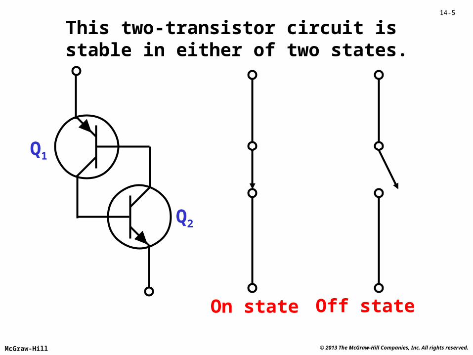
14-5
McGraw-Hill © 2013 The McGraw-Hill Companies, Inc. All rights reserved.
This two-transistor circuit isstable in either of two states.
On state Off state
Q1
Q2

14-6
McGraw-Hill © 2013 The McGraw-Hill Companies, Inc. All rights reserved.
Q1
Q2
p
p
n
n
A four-layer structure replacesthe two-transistor circuit.
Q1}{Q2

14-7
McGraw-Hill © 2013 The McGraw-Hill Companies, Inc. All rights reserved.
The silicon controlled rectifier (SCR)
Q1
Q2
Anode
Gate
Cathode
p
p
n
n
Anode
Gate
Cathode
Anode
Gate
Cathode

14-8
McGraw-Hill © 2013 The McGraw-Hill Companies, Inc. All rights reserved.
Gate
Anode
CathodeL
oad
curr
ent
TimeGate pulseoccurs here
LoadWith a dc source, the SCR stays
on after it is gated.
The SCR can be turned on at its gate terminal.

14-9
McGraw-Hill © 2013 The McGraw-Hill Companies, Inc. All rights reserved.
Gate
Anode
Cathode
Loa
dcu
rren
t
TimeGate pulseoccurs here
LoadWith an ac source, the SCR turnsoff at the
zero-crossing.
Turns off here
on
offCommutation (turn-off) is
automatic with an ac source.

14-10
McGraw-Hill © 2013 The McGraw-Hill Companies, Inc. All rights reserved.
Gate
Anode
Cathode
Loa
dcu
rren
t
Time
LoadThe gate canbe pulsed foreach positivealternation.

14-11
McGraw-Hill © 2013 The McGraw-Hill Companies, Inc. All rights reserved.
Gate
Anode
Cathode
Loa
dcu
rren
t
Time
LoadThe averageload current
can bedecreasedby gating
the SCR later.

14-12
McGraw-Hill © 2013 The McGraw-Hill Companies, Inc. All rights reserved.
Gate
Anode
Cathode
Loa
dcu
rren
t
Time
Load…. and later.

14-13
McGraw-Hill © 2013 The McGraw-Hill Companies, Inc. All rights reserved.
Gate
Anode
Cathode
Loa
dcu
rren
t
Time
Load…. or, notat all.
No gate pulses: ILoad = 0
0

14-14
McGraw-Hill © 2013 The McGraw-Hill Companies, Inc. All rights reserved.
Concept Review• An NPN-PNP latch can be either on or off.• Once gated on, the latch cannot be gated off.• Silicon controlled rectifiers (SCRs) are latches.• An SCR is turned on by applying a pulse to its
gate terminal.• With a dc source, the SCR stays on after it is
gated.• With an ac source, the SCR turns off at the zero
crossing.• Load power is controlled by gating the SCR
earlier or later during the ac cycle.
Repeat Segment

14-15
McGraw-Hill © 2013 The McGraw-Hill Companies, Inc. All rights reserved.
Concept Preview• An SCR, in conjunction with a bridge rectifier,
can provide full-wave control.• Two SCRs can provide full-wave control without
a bridge rectifier.• A triac is equivalent to two SCRs.• Solid state relays combine triacs and optoisolators
in a single package.• SCRs and triacs are both members of the thyristor
family.• A diac breaks down in both directions and is ideal
for gating triacs.

14-16
McGraw-Hill © 2013 The McGraw-Hill Companies, Inc. All rights reserved.
Load
A full-wave rectifier allows use of both alternations.
Bridge rectifier
Load current
Gate

14-17
McGraw-Hill © 2013 The McGraw-Hill Companies, Inc. All rights reserved.
Load
Two SCRs can providefull-wave control.
Gated early for full power
Gated later for low power
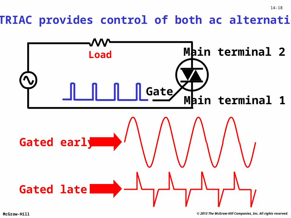
14-18
McGraw-Hill © 2013 The McGraw-Hill Companies, Inc. All rights reserved.
Load
Main terminal 1
Main terminal 2
Gate
The TRIAC provides control of both ac alternations.
Gated early
Gated late

14-19
McGraw-Hill © 2013 The McGraw-Hill Companies, Inc. All rights reserved.
Solid state relays provide optical isolation.

14-20
McGraw-Hill © 2013 The McGraw-Hill Companies, Inc. All rights reserved.
DIAC volt-ampere characteristic curves
+I
-I
+V-V
VP+
VP-

14-21
McGraw-Hill © 2013 The McGraw-Hill Companies, Inc. All rights reserved.
Load
A popular diac-triac control circuit
Decreasing R will gate the TRIAC
earlier.

14-22
McGraw-Hill © 2013 The McGraw-Hill Companies, Inc. All rights reserved.
Illustration courtesy Powerex, Inc.

14-23
McGraw-Hill © 2013 The McGraw-Hill Companies, Inc. All rights reserved.
Thyristor quiz
The three terminals of an SCR are anode,cathode and _________. gate
SCR turnoff in ac circuits occurs at the__________ crossing. zero
In ac control, load power is increased by gatingthe SCR ______ in the cycle. earlier
The device equivalent to two SCRs for full-wave control is the __________. triac
The diode often used to trigger triacs is the_________. diac

14-24
McGraw-Hill © 2013 The McGraw-Hill Companies, Inc. All rights reserved.
Concept Review• An SCR, in conjunction with a bridge rectifier,
can provide full-wave control.• Two SCRs can provide full-wave control without
a bridge rectifier.• A triac is equivalent to two SCRs.• Solid state relays combine triacs and optoisolators
in a single package.• SCRs and triacs are both members of the thyristor
family.• A diac breaks down in both directions and is ideal
for gating triacs.
Repeat Segment

14-25
McGraw-Hill © 2013 The McGraw-Hill Companies, Inc. All rights reserved.
Concept Preview• Servos use negative feedback to provide accurate
velocity or positioning.• A velocity servo compares tachometer voltage
with a set voltage.• A position serve compares potentiometer voltage
with a set voltage.• Servo response can be critically damped (most
desired), overdamped, or underdamped.• Servos are tuned for the best response by adjusting
gain and phase.

14-26
McGraw-Hill © 2013 The McGraw-Hill Companies, Inc. All rights reserved.
Servomechanisms use negative feedback to control velocity and/or position.
Motor
Tachometer
ErrorAmplifier
Negative feedback
Velocityset
VREF
If the mechanical load changes, causing the velocityto change, the error amplifier will respond by
adjusting the motor drive to reduce the change.

14-27
McGraw-Hill © 2013 The McGraw-Hill Companies, Inc. All rights reserved.
Motor
ErrorAmplifier
Positionset
VREF
VREFGearbox
In this servo,gears drive a
variable resistor to provide
position feedback.
Feedback

14-28
McGraw-Hill © 2013 The McGraw-Hill Companies, Inc. All rights reserved.
Pos
itio
n
Time
t1
Suppose, at time t1, a servo is commanded to a new position.
This is the ideal response

14-29
McGraw-Hill © 2013 The McGraw-Hill Companies, Inc. All rights reserved.
Pos
itio
n
Time
t1
This is the critically damped response

14-30
McGraw-Hill © 2013 The McGraw-Hill Companies, Inc. All rights reserved.
Pos
itio
n
Time
t1
This is the overdamped response

14-31
McGraw-Hill © 2013 The McGraw-Hill Companies, Inc. All rights reserved.
Pos
itio
n
Time
t1
This is the underdamped response

14-32
McGraw-Hill © 2013 The McGraw-Hill Companies, Inc. All rights reserved.
Pos
itio
n
Time
Tuning a servomechanism involves adjusting the loop gain and the phase
to achieve the best response.
Which response is the best?

14-33
McGraw-Hill © 2013 The McGraw-Hill Companies, Inc. All rights reserved.
The green revolution involves lots of ideas and many new technologies and one very important part of the movement is efficiency. For example, to realize the best recovery of electrical energy from a photovoltaic panel a MPPT controller is needed.
Changes in illumination cause changes in the maximum power point. The controller optimizes the load on the panel under varying conditions.

14-34
McGraw-Hill © 2013 The McGraw-Hill Companies, Inc. All rights reserved.
Here, we see a MPPT controller and a separate inverter.
MPPTcontroller
Inverter
Storagebattery
ACloadsDC
loads
14-35
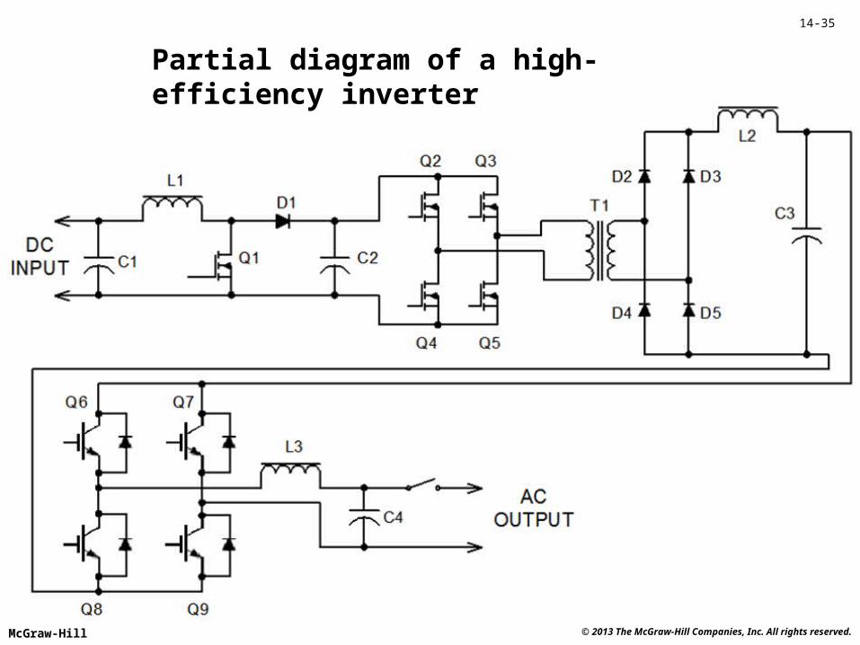
McGraw-Hill © 2013 The McGraw-Hill Companies, Inc. All rights reserved.
Partial diagram of a high-efficiency inverter

14-36
McGraw-Hill © 2013 The McGraw-Hill Companies, Inc. All rights reserved.
LEDs are increasingly replacing less efficient light sources. This circuit offers high efficiency and dimming.

14-37
McGraw-Hill © 2013 The McGraw-Hill Companies, Inc. All rights reserved.
Troubleshooting
• SCRs can fail by opening or shorting.
• A shorted SCR means full load power.
• An open SCR means no load power.
• A defective gate circuit can produce either full power or no power.
• TRIAC troubleshooting is much the same.

14-38
McGraw-Hill © 2013 The McGraw-Hill Companies, Inc. All rights reserved.
Servo Troubleshooting
• Mechanical problems can be confused with electrical faults.
• Slippage and excessive mechanical play can cause various symptoms and should be eliminated before tuning or troubleshooting.
• The underdamped response is often caused by excessive gain.
• The overdamped response is often caused by insufficient gain.

14-39
McGraw-Hill © 2013 The McGraw-Hill Companies, Inc. All rights reserved.
Servo quiz
Servos use negative _________ to controlposition or speed. feedback
When servo response is sluggish, theresponse is ___________. overdamped
When servo response is oscillatory, theresponse is ___________. underdamped
The overdamped response can be causedby _________ gain. insufficient
The underdamped response can be causedby _________ gain. excessive

14-40
McGraw-Hill © 2013 The McGraw-Hill Companies, Inc. All rights reserved.
Concept Review• Servos use negative feedback to provide accurate
velocity or positioning.• A velocity servo compares tachometer voltage
with a set voltage.• A position serve compares potentiometer voltage
with a set voltage.• Servo response can be critically damped (most
desired), overdamped, or underdamped.• Servos are tuned for the best response by adjusting
gain and phase.
Repeat Segment

14-41
McGraw-Hill © 2013 The McGraw-Hill Companies, Inc. All rights reserved.
REVIEW
• The Silicon Controlled Rectifier• Full-Wave Devices• Feedback in Control Circuitry• Managing Energy• Troubleshooting


