!
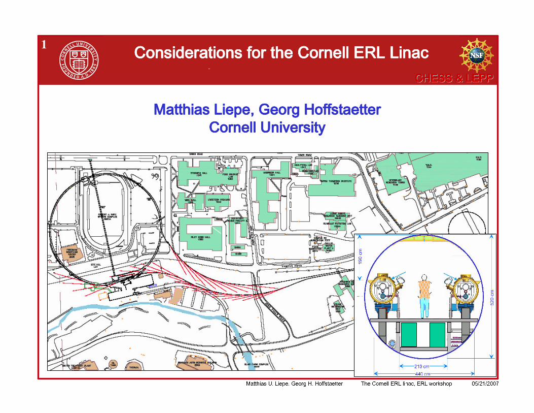
1
!
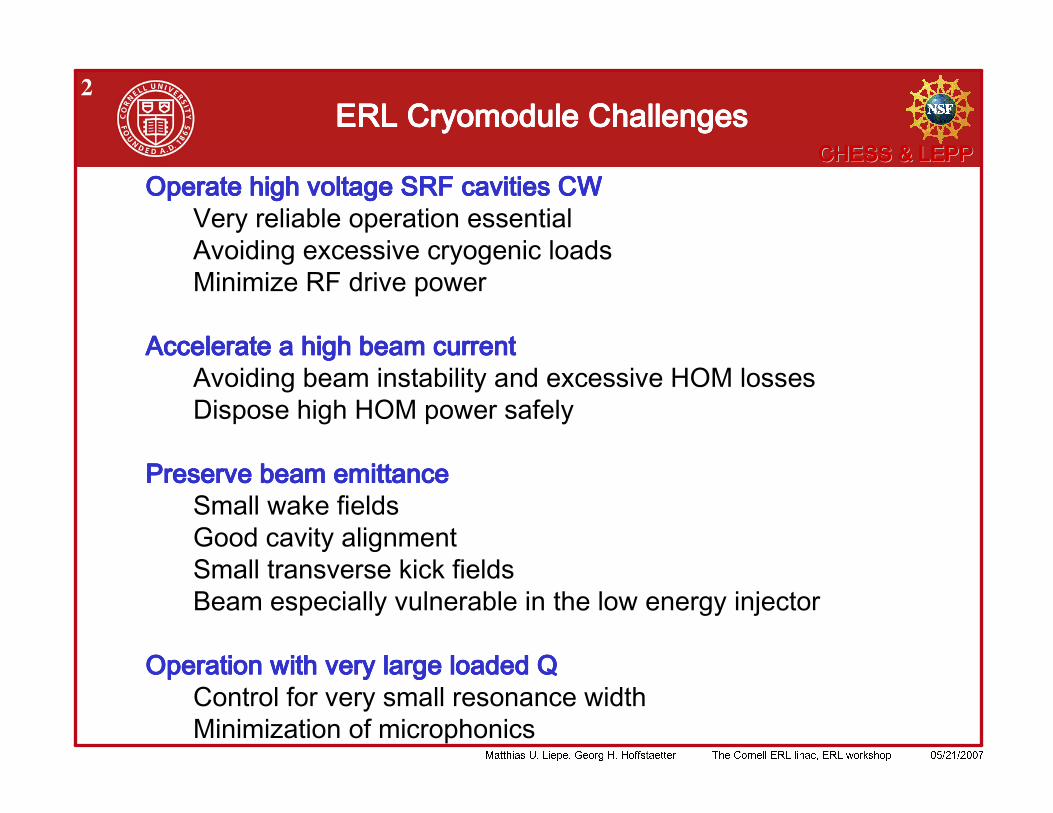
2
! " ! ! # $ %
&
!
3
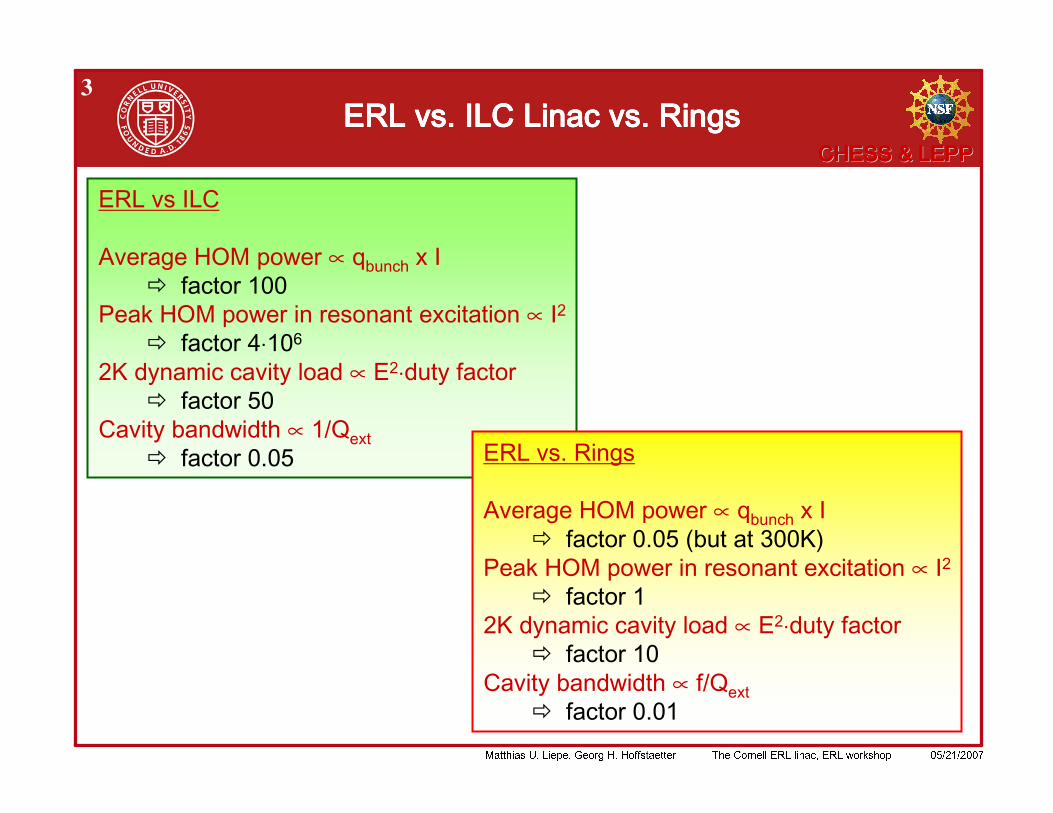
2.5kHz vs 20Hz
(5*0.3MV)^2/100Ohm Vs. (16*0.8MV)^2/700Ohm
1Ohm, 400mA^2 – 7Ohm, 200mA^2
400 mA, 22nC, 0.4V/pCVs 200mA, 0.08nC, 10V/pC
0.05 mA, 3nC – 200mA, 0.08nC
∝
∝ ⋅
! " # $ # % " ∝ ⋅ " & # '
# ( " " ) ∝ * + , ' ,
∝ , ' - ( & . ! /
∝
! " # $ # % " ∝ ⋅ " & #
# ( " " ) ∝ * + ,
!
4
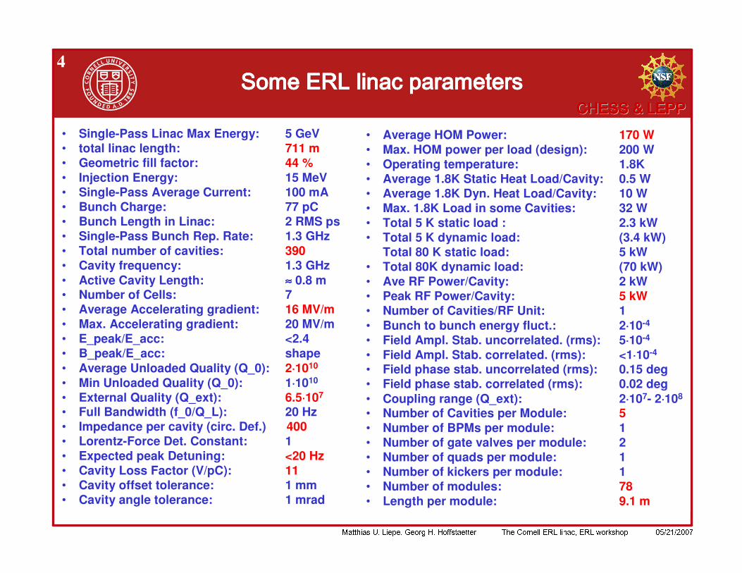
• Single-Pass Linac Max Energy: 5 GeV • total linac length: 711 m• Geometric fill factor: 44 %• Injection Energy: 15 MeV • Single-Pass Average Current: 100 mA • Bunch Charge: 77 pC• Bunch Length in Linac: 2 RMS ps• Single-Pass Bunch Rep. Rate: 1.3 GHz • Total number of cavities: 390• Cavity frequency: 1.3 GHz • Active Cavity Length: ≈≈≈≈ 0.8 m • Number of Cells: 7 • Average Accelerating gradient: 16 MV/m• Max. Accelerating gradient: 20 MV/m • E_peak/E_acc: <2.4 • B_peak/E_acc: shape• Average Unloaded Quality (Q_0): 2⋅⋅⋅⋅1010
• Min Unloaded Quality (Q_0): 1⋅⋅⋅⋅1010
• External Quality (Q_ext): 6.5⋅⋅⋅⋅107
• Full Bandwidth (f_0/Q_L): 20 Hz • Impedance per cavity (circ. Def.) 400• Lorentz-Force Det. Constant: 1 • Expected peak Detuning: <20 Hz• Cavity Loss Factor (V/pC): 11• Cavity offset tolerance: 1 mm• Cavity angle tolerance: 1 mrad
• Average HOM Power: 170 W• Max. HOM power per load (design): 200 W• Operating temperature: 1.8K • Average 1.8K Static Heat Load/Cavity: 0.5 W • Average 1.8K Dyn. Heat Load/Cavity: 10 W • Max. 1.8K Load in some Cavities: 32 W• Total 5 K static load : 2.3 kW • Total 5 K dynamic load: (3.4 kW)
Total 80 K static load: 5 kW• Total 80K dynamic load: (70 kW) • Ave RF Power/Cavity: 2 kW • Peak RF Power/Cavity: 5 kW • Number of Cavities/RF Unit: 1 • Bunch to bunch energy fluct.: 2⋅⋅⋅⋅10-4
• Field Ampl. Stab. uncorrelated. (rms): 5⋅⋅⋅⋅10-4
• Field Ampl. Stab. correlated. (rms): <1⋅⋅⋅⋅10-4
• Field phase stab. uncorrelated (rms): 0.15 deg• Field phase stab. correlated (rms): 0.02 deg• Coupling range (Q_ext): 2⋅⋅⋅⋅107- 2⋅⋅⋅⋅108
• Number of Cavities per Module: 5 • Number of BPMs per module: 1• Number of gate valves per module: 2• Number of quads per module: 1• Number of kickers per module: 1• Number of modules: 78• Length per module: 9.1 m
!
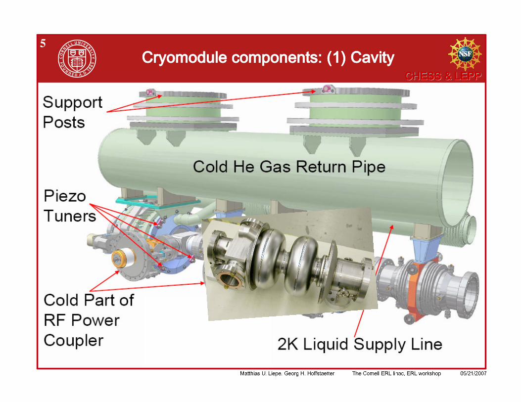
5
!
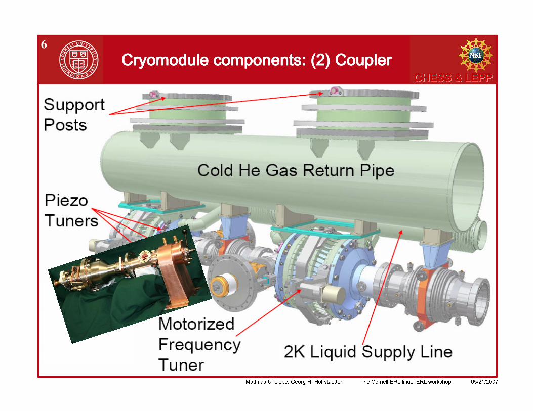
6
!
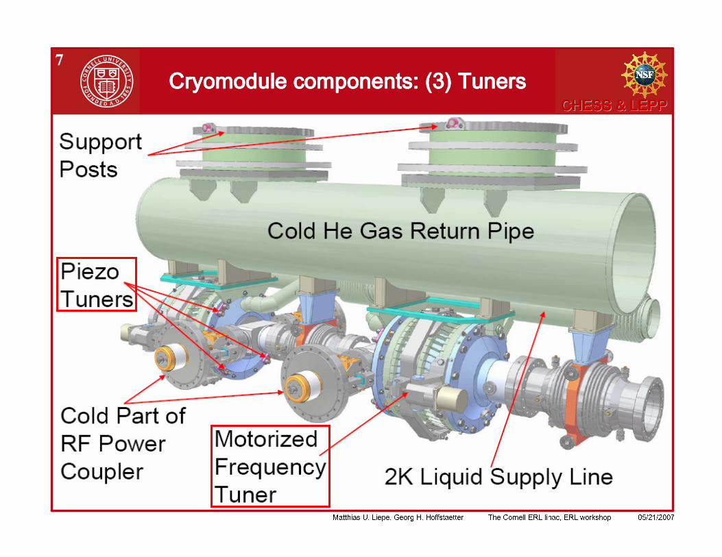
7 ! " ! " ! " ! "
!
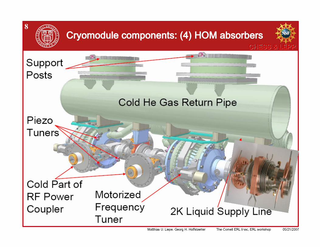
8 # $ % & ' ' # $ % & ' ' # $ % & ' ' # $ % & ' '
!
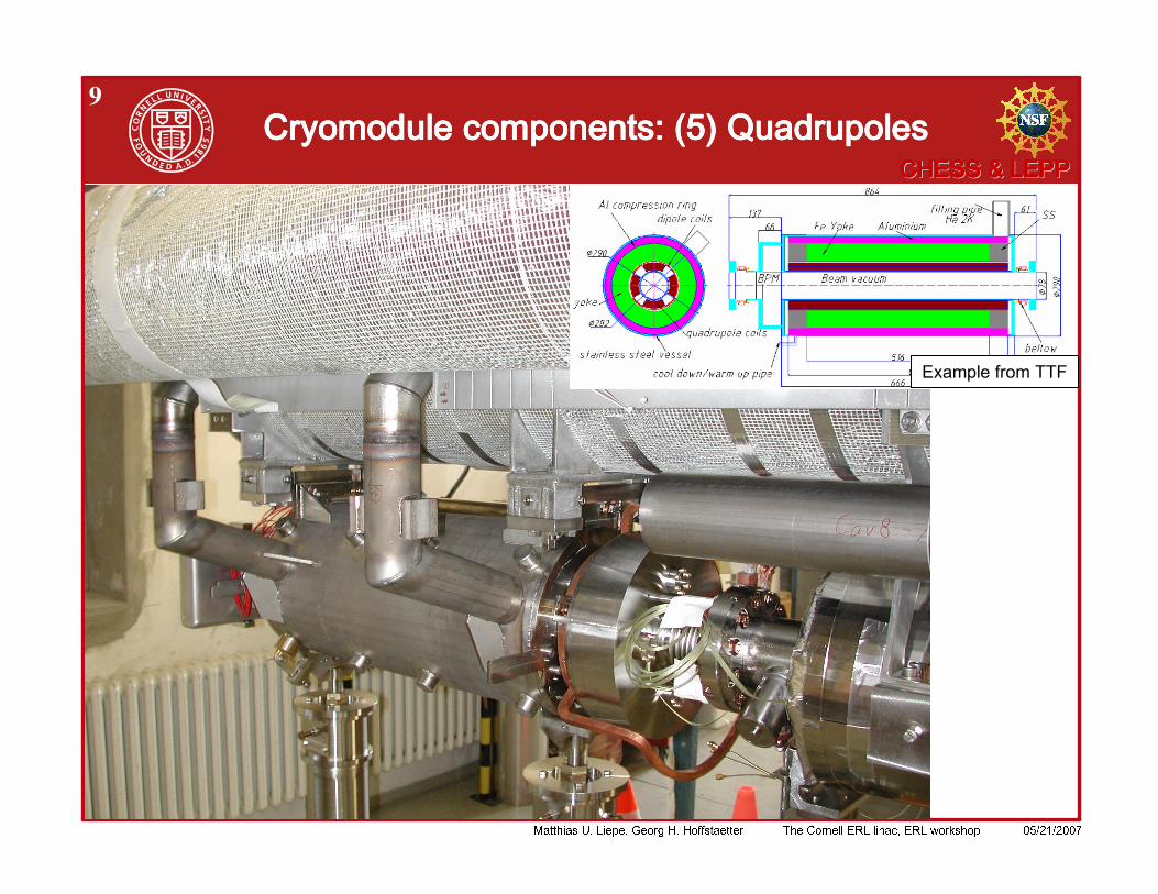
9 ( ( ( ( ) ) ) )
!
10
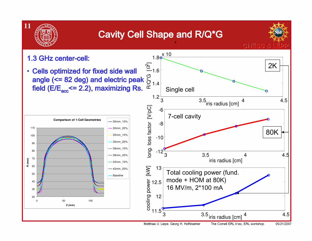
' ( / ) % % % " # $ % % "
/ $ 0 " # ) ( / % + 1 * $ & 1 , 2 !
/ ) % % % % " ) ) % ( % # % " / % 1 3 4 * $
. / ) % % ) ) & % " / 5 & $ ( % % 1 6( / 7 $ " $ ( ( 1 ' . * . 8 $ $
/ ) % % % $ ) % " / 9 & $ $ 0 & & % ( # & ( % $ & % ( / # % $ % 1 $ $ - " $ " % " & " # /
!
11 * ) + , * ) + , * ) + , * ) + ,
Comparison of 1-Cell Geometries
25
35
45
55
65
75
85
95
105
115
0 50 100
Z (mm)
R (m
m)
30mm_10%
30mm_20%
35mm_10%
35mm_20%
39mm_10%
39mm_20%
43mm_10%
43mm_20%
Baseline
: ! " ! " ! " ! " #$ #$ #$ #$ #### ! % ! % ! % ! % & & & &
3 3.5 4 4.5-12
-10
-8
-6
iris radius [cm]
long
. los
s fa
ctor
[V
/pC
]
3 3.5 4 4.51.2
1.4
1.6
1.8x 10
4
iris radius [cm]
R/Q
*G [
Ω2]
3 3.5 4 4.511.5
12
12.5
13
cool
ing
pow
er [
kW]
iris radius [cm]
! " # $
%& ' (
)
!
2 !
!
12
10 15 20 250
100
200
300
400total cost
cost
[ar
b. u
nits
]
field gradient [MV/m]
capitaloperationtotal
10 15 20 250
50
100
150capital cost
cost
[ar
b. u
nits
]
field gradient [MV/m]
tunnellinacRFcryo
10 15 20 250
50
100
150
200operating cost
cost
[ar
b. u
nits
]
field gradient [MV/m]
RFcryo
10 15 20 25200
300
400
500
600tunnel length
leng
th [
m]
field gradient [MV/m]10 15 20 25
200
400
600
800number of cavities
#
field gradient [MV/m]10 15 20 25
109
1010
1011
cavity Q0
Q0
field gradient [MV/m]
10 15 20 250
2
4
6IOT peak power
pow
er [k
W]
field gradient [MV/m]10 15 20 250
10
20
30cryo AC power
pow
er [M
W]
field gradient [MV/m]10 15 20 250
10
20
30cryo power fractions
pow
er [M
W]
field gradient [MV/m]
cav. dyn.HOMinput Cstatic
!
13% % % %
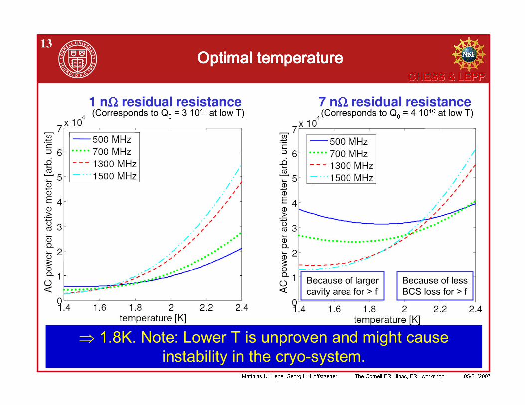
1 nΩΩΩΩ residual resistance 7 nΩΩΩΩ residual resistance
" # " " # #
!
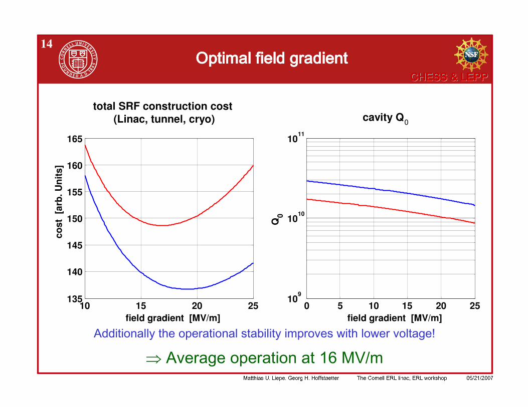
14% % % %
10 15 20 25135
140
145
150
155
160
165
total SRF construction cost (Linac, tunnel, cryo)
cost
[ar
b. U
nits
]
field gradient [MV/m]0 5 10 15 20 25
109
1010
1011
cavity Q0
Q0
field gradient [MV/m]
! " # " " % % # ) % ( % # $ ) % % ;
!
15
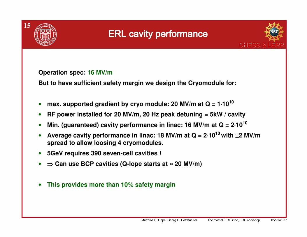
Operation spec: 16 MV/m
But to have sufficient safety margin we design the Cryomodule for:
• max. supported gradient by cryo module: 20 MV/m at Q = 1⋅⋅⋅⋅1010
• RF power installed for 20 MV/m, 20 Hz peak detuning = 5kW / cavity
• Min. (guaranteed) cavity performance in linac: 16 MV/m at Q = 2⋅⋅⋅⋅1010
• Average cavity performance in linac: 18 MV/m at Q = 2⋅⋅⋅⋅1010 with ±±±±2 MV/m spread to allow loosing 4 cryomodules.
• 5GeV requires 390 seven-cell cavities !
• Can use BCP cavities (Q-lope starts at ≈≈≈≈ 20 MV/m)
• This provides more than 10% safety margin
!
16
< , ' ( ) ' ( ) ' ( ) ' ( ) * + , , ,* + , , ,* + , , ,* + , , ,
) ) ) ) ) ) ) )
' + - . +' + - . +' + - . +' + - . + ) ) ) )
" " " " $ % & $ % & $ % & $ % & - - - -
!
17
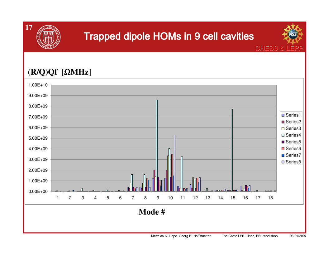
< , ' ( ) ' ( ) ' ( ) ' ( ) * + , , ,* + , , ,* + , , ,* + , , ,
" " " " $ % & $ % & $ % & $ % & - - - -
0.00E+00
1.00E+09
2.00E+09
3.00E+09
4.00E+09
5.00E+09
6.00E+09
7.00E+09
8.00E+09
9.00E+09
1.00E+10
1 2 3 4 5 6 7 8 9 10 11 12 13 14 15 16 17 18
Series1Series2Series3Series4Series5Series6Series7Series8
(R/Q)Qf [ΩΩΩΩMHz]
Mode #

!
18
Dimensions are optimized to reduce Q*(R/Q) of worst HOM until as many HOMs as possible are about equal.
Example: End cell shape has significant impact
Limitations of these optimizations:• HOMs couple through large beam tubes:
– Some modes will have high R/Q– Difficult to simulate. Actual R/Q strongly impacted by fluctuation in cavity
shapes• Still to be analyzed: Coupling of main input coupler to HOMs.
$ % & . / $ % & . / $ % & . / $ % & . /
!
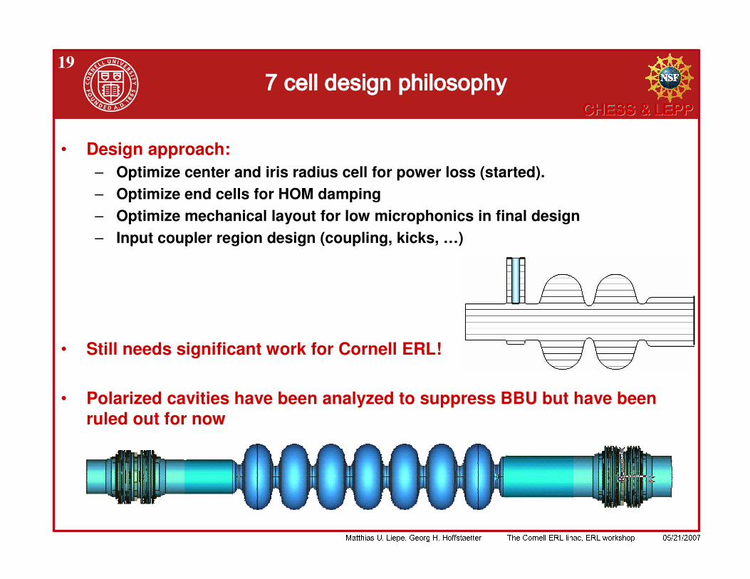
19/ / / /
• Design approach:– Optimize center and iris radius cell for power loss (started).– Optimize end cells for HOM damping– Optimize mechanical layout for low microphonics in final design– Input coupler region design (coupling, kicks, …)
• Still needs significant work for Cornell ERL!
• Polarized cavities have been analyzed to suppress BBU but have been ruled out for now
!
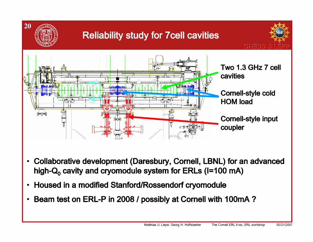
20' / ' / ' / ' /
! ! ! ! " # $ % % & " # $ % % & " # $ % % & " # $ % % &
' ( )' ( )' ( )' ( ) ! ! ! ! ! ! ! ! * + % % , ) - $ % % & .* + % % , ) - $ % % & .* + % % , ) - $ % % & .* + % % , ) - $ % % & .
/ 0 / 0 / 0 / 0 1 1 1 1
2 2 2 2 3 ' 3 ' 3 ' 3 ' 2 ) 2 ) 2 ) 2 ) ) ) ) )

!
21& & & & ) ) ) )
• Cavity and cryostat design for low microphonics• Active frequency control (fast frequency tuner)• Lacking detailed knowledge, we work with 20Hz peak detuning.
-75 -50 -25 0 25 50 75 1000
0.2
0.4
0.6
0.8
1
! "
-75 -50 -25 0 25 50 75 100
0.2
0.4
0.6
0.8
1
# $
!
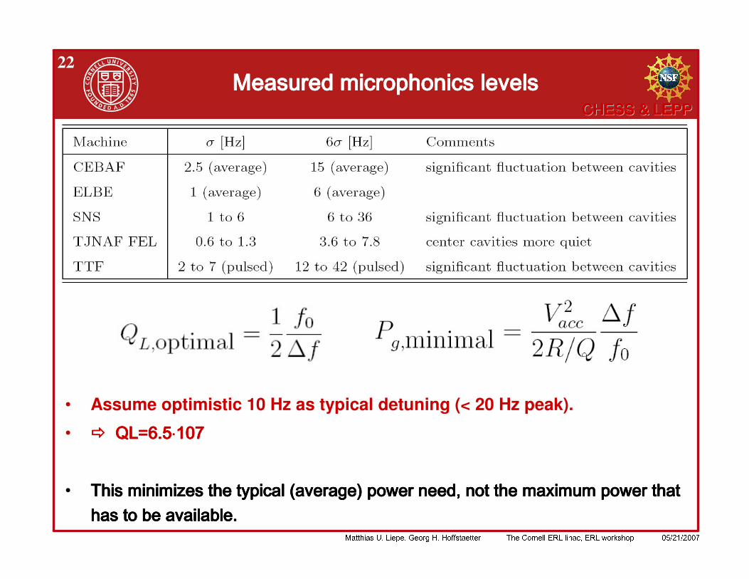
22& & & &
• Assume optimistic 10 Hz as typical detuning (< 20 Hz peak).
: 4 5 6 74 5 6 74 5 6 74 5 6 7 ⋅⋅⋅⋅8 08 08 08 0
: / ( ( 2 1 ! % ( ) / ( ( 2 1 ! % ( ) / ( ( 2 1 ! % ( ) / ( ( 2 1 ! % ( ) ( ( ( ( ( 9 1 9 ( 9 1 9 ( 9 1 9 ( 9 1 9
!
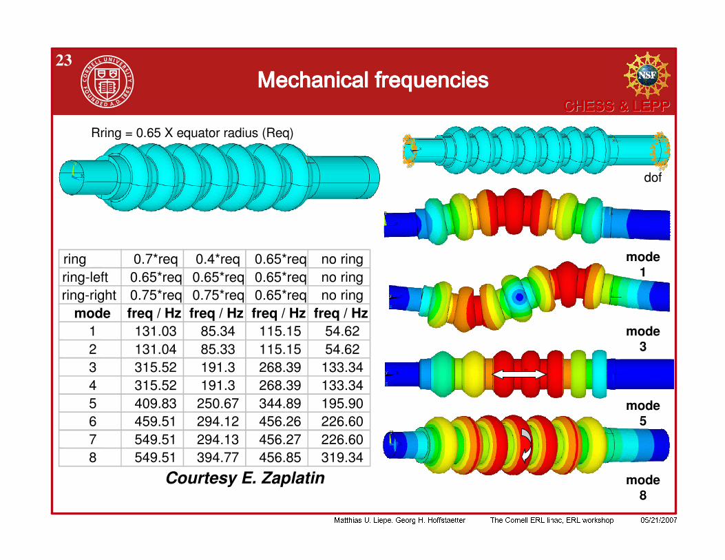
23& 0 & 0 & 0 & 0
Rring = 0.65 X equator radius (Req)
dof
mode 1
mode 8
mode 5
mode 3
ring 0.7*req 0.4*req 0.65*req no ringring-left 0.65*req 0.65*req 0.65*req no ringring-right 0.75*req 0.75*req 0.65*req no ring
mode freq / Hz freq / Hz freq / Hz freq / Hz1 131.03 85.34 115.15 54.622 131.04 85.33 115.15 54.623 315.52 191.3 268.39 133.344 315.52 191.3 268.39 133.345 409.83 250.67 344.89 195.906 459.51 294.12 456.26 226.607 549.51 294.13 456.27 226.608 549.51 394.77 456.85 319.34
Courtesy E. Zaplatin
!
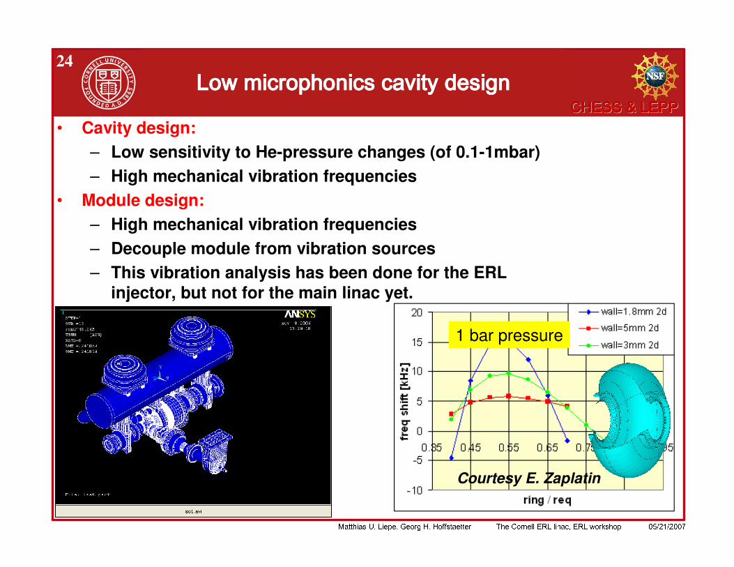
241 1 1 1
• Cavity design:– Low sensitivity to He-pressure changes (of 0.1-1mbar)– High mechanical vibration frequencies
• Module design:– High mechanical vibration frequencies– Decouple module from vibration sources– This vibration analysis has been done for the ERL
injector, but not for the main linac yet.
1 bar pressure
Courtesy E. Zaplatin
!
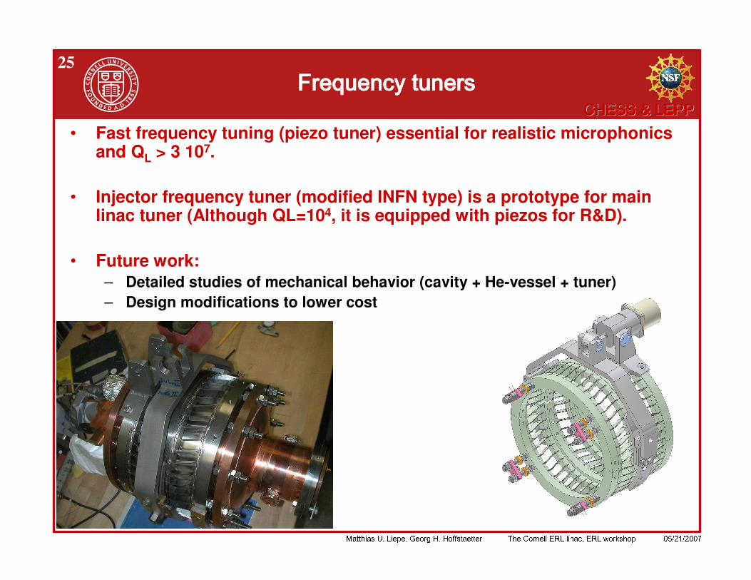
252 0 2 0 2 0 2 0
• Fast frequency tuning (piezo tuner) essential for realistic microphonicsand QL > 3 107.
• Injector frequency tuner (modified INFN type) is a prototype for main linac tuner (Although QL=104, it is equipped with piezos for R&D).
• Future work:– Detailed studies of mechanical behavior (cavity + He-vessel + tuner)– Design modifications to lower cost
!
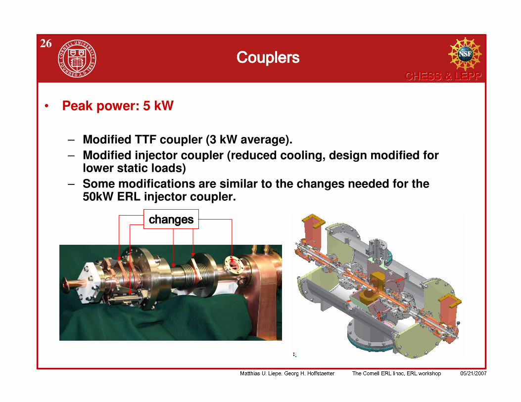
26
• Peak power: 5 kW
– Modified TTF coupler (3 kW average).– Modified injector coupler (reduced cooling, design modified for
lower static loads)– Some modifications are similar to the changes needed for the
50kW ERL injector coupler.
( ( ( (
!
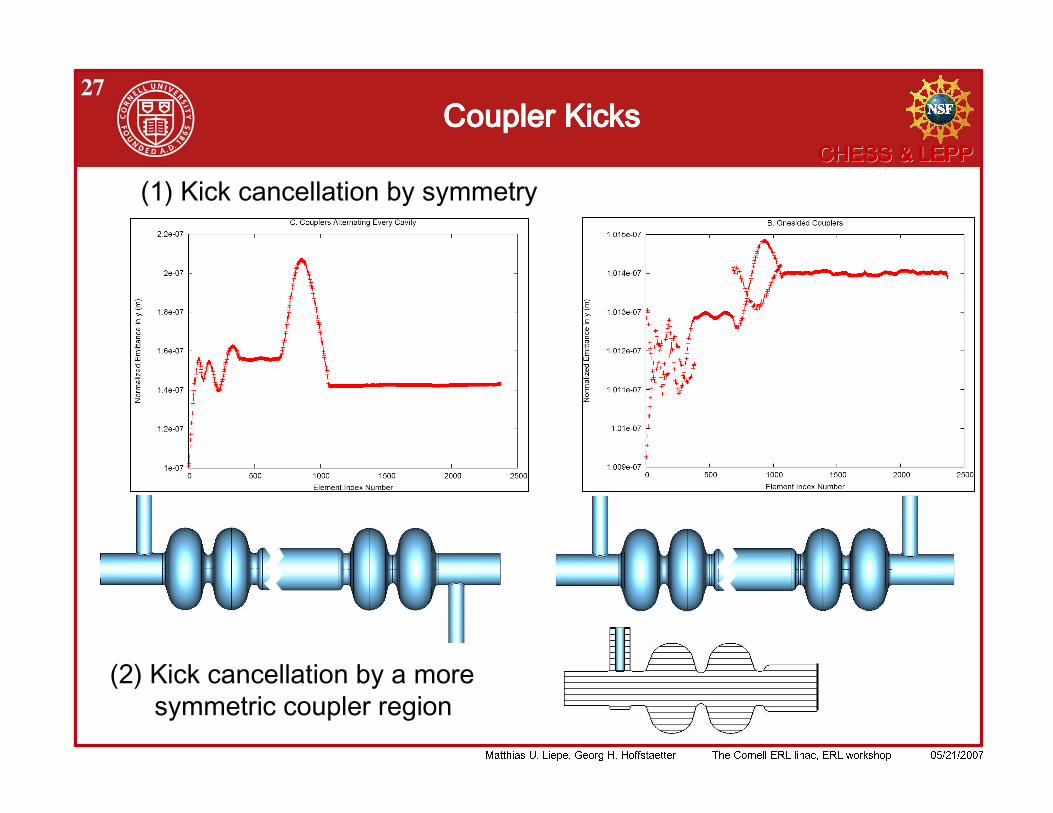
27 3 4 3 4 3 4 3 4

!
28$ ' ' $ ' ' $ ' ' $ ' '
: 9 3 ' 9 9 9 1 9 3 ' 9 9 9 1 9 3 ' 9 9 9 1 9 3 ' 9 9 9 1 = + ( : & - #& 5 ; 2 9 ) 9 + ( : & - #& 5 ; 2 9 ) 9 + ( : & - #& 5 ; 2 9 ) 9 + ( : & - #& 5 ; 2 9 ) 9 < < = ! < < = ! < < = ! < < = ! = # ) 9 3 ' # ) 9 3 ' # ) 9 3 ' # ) 9 3 ' = + ( ( + ( ( + ( ( + ( ( % % % % > ) ) > ) ) > ) ) > ) ) 9 9 9 9
) 9 ) 9 ) 9 ) 9 = < ) ( ) 8 8 < ) ( ) 8 8 < ) ( ) 8 8 < ) ( ) 8 8 1 1 1 1 8 8 + ! 1 0 8 8 + ! 1 0 8 8 + ! 1 0 8 8 + ! 1 0 1 1 1 1 ! ! ! !
' 9 9 9 0 8 ' 9 9 9 0 8 ' 9 9 9 0 8 ' 9 9 9 0 8 1 1 1 1 8 ? !8 ? !8 ? !8 ? != & 3 ' ) 8 ? 1 & 3 ' ) 8 ? 1 & 3 ' ) 8 ? 1 & 3 ' ) 8 ? 1 ( ( ( (
( " @ 8 8 ? ( " @ 8 8 ? ( " @ 8 8 ? ( " @ 8 8 ? : - ) ) " - ) ) " - ) ) " - ) ) "
= ' ) ' ) ' ) ' ) = . 1 ( ( ( . 1 ( ( ( . 1 ( ( ( . 1 ( ( ( ) ) ) )
9 9 9 9
1.8K 80K80K
!
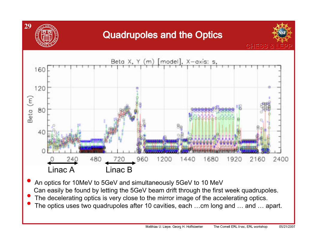
29) ) ) ) % % % %
•
! " ! " # $ $ $
!
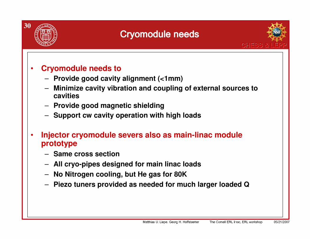
30
• Cryomodule needs to– Provide good cavity alignment (<1mm)– Minimize cavity vibration and coupling of external sources to
cavities– Provide good magnetic shielding– Support cw cavity operation with high loads
• Injector cryomodule severs also as main-linac module prototype– Same cross section– All cryo-pipes designed for main linac loads– No Nitrogen cooling, but He gas for 80K– Piezo tuners provided as needed for much larger loaded Q
!
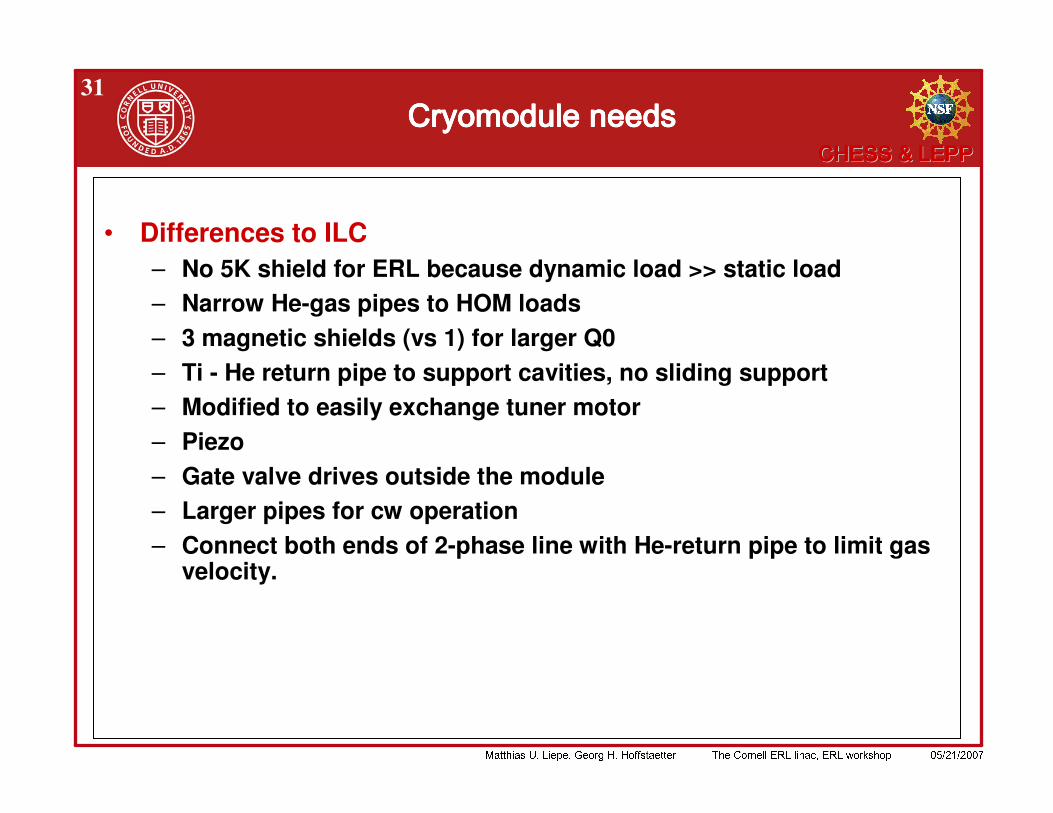
31
• Differences to ILC– No 5K shield for ERL because dynamic load >> static load– Narrow He-gas pipes to HOM loads– 3 magnetic shields (vs 1) for larger Q0– Ti - He return pipe to support cavities, no sliding support– Modified to easily exchange tuner motor– Piezo– Gate valve drives outside the module – Larger pipes for cw operation– Connect both ends of 2-phase line with He-return pipe to limit gas
velocity.
!
32
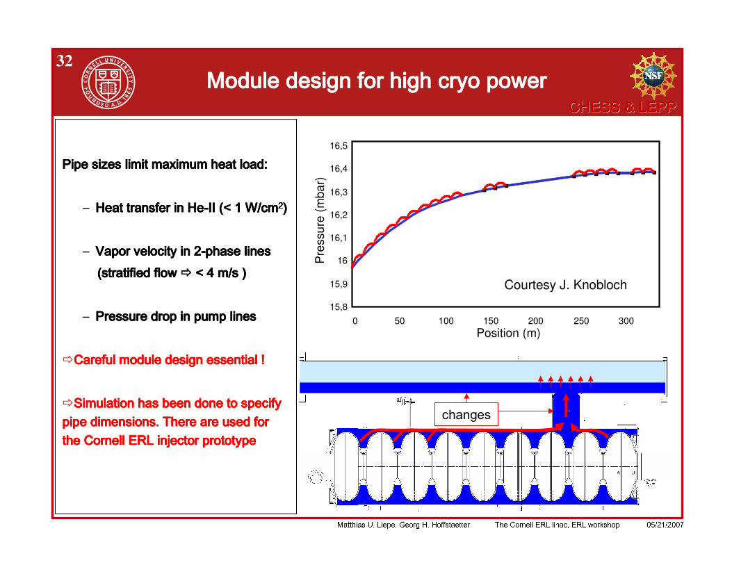
% $$ $$
% ! " ! " ! " ! " # # # # $ $ $ $
%
% & '% & '% & '% & '
( ) ! ( ) ! ( ) ! ( ) ! * + * + * + * + % , - . / ! % , - . / ! % , - . / ! % , - . / !
15,8
15,9
16
16,1
16,2
16,3
16,4
16,5
0 50 100 150 200 250 300Position (m)
Pre
ssur
e (m
bar)
Courtesy J. Knobloch
& & & & 1 1 1 1
"
!
33
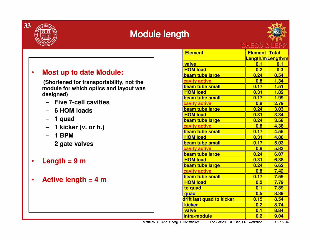
• Most up to date Module:(Shortened for transportability, not the module for which optics and layout was designed)
– Five 7-cell cavities– 6 HOM loads– 1 quad– 1 kicker (v. or h.)– 1 BPM– 2 gate valves
• Length = 9 m
• Active length = 4 m
Element Element Total Length/mLength/m
valve 0.1 0.1HOM load 0.2 0.3beam tube large 0.24 0.54cavity active 0.8 1.34beam tube small 0.17 1.51HOM load 0.31 1.82beam tube small 0.17 1.99cavity active 0.8 2.79beam tube large 0.24 3.03HOM load 0.31 3.34beam tube large 0.24 3.58cavity active 0.8 4.38beam tube small 0.17 4.55HOM load 0.31 4.86beam tube small 0.17 5.03cavity active 0.8 5.83beam tube large 0.24 6.07HOM load 0.31 6.38beam tube large 0.24 6.62cavity active 0.8 7.42beam tube small 0.17 7.59HOM load 0.2 7.79to quad 0.1 7.89quad 0.5 8.39
drift last quad to kicker 0.15 8.54kicker 0.2 8.74valve 0.1 8.84intra-module 0.2 9.04
& & & &
!
34
• Full main linac module design based on injector module design.
• Open issues:– Verification of HOM load operation– Verification of magnetic shielding for highest Q0 Design optimization for low microphonics Study best way to regulate cooling of HOM loads individually– Synchrotron radiation shielding of cavities– Beam collimation. Beam loss, radiation, and heating (especially for cavities
at linac end)
5 6 5 6 5 6 5 6
!
35
•
• ! " ! # $ • % ! " &• & ' • ( ) ' • • * &
+ ,
+ - + & & . /& &


