
Miller Leaman’s Helix Screen filter models are available in three different sizes: 2”, 2” Super and 3”.
The filters can be installed in any orientation; however, it is preferable to install them in the inverted
position (3/4” flush port at bottom). This helps the filtration system work at it’s optimum. As water enters
the filter housing, a high velocity centrifugal action occurs, spiraling heavier particles (sediment, scale, etc.)
away from the screen cartridge, down to the base of the filter. These accumulated particles are then flushed
from the filter via the 3/4” flush port connection at the base
of the filter (valve not included).
HOW IT WORKS
1. Dirty water enters the filter housing through the inlet connection.
2. As dirty water passes through the Helix-Element, the water starts to spin at high velocity. This centrifugal action spins the particles away from the screen, minimizing manual cleaning frequency.
3. As particles are spun down to the base of the filter, they are flushed via the 3/4” female threaded flush port connection.
4. The dirty water passes from the outside to the inside of the stainless steel screen. The screen captures the remaining light and fibrous contaminants from the water.
5. After passing through the screen, the filtered water flows upward and exits the filter through one of the outlets.The outlet not being used is terminated with a threaded cap.
UNIQUE FEATURES• Centrifugal cleaning action minimizes maintenance
• Large screen surface area with maximum open area
• Particles can be flushed while filter is in operation
• Several Type 316 stainless steel mesh(and perforated) options available
• Durable, corrosion-resistant, injection molded housing
• Easily removable, quick clamp lid assembly
• Pressure gauge ports molded into housing
THE CLOSUREManufactured in Type 316 stainless steel, the
quick-release clamp assembly is strong and reliable.
No tools are necessary to remove the clamp and
filter cover when maintenance is required.
THE BODYThe body contains one inlet and two outlets, allowing the
filter to be installed at either 90 or 180-degrees. A
threaded cap is supplied with the filter to terminate the
outlet port not being used. Inlet/outlet connections are
available in NPT or Victaulic. The body contains inlet and
outlet pressure gauge ports (gauges not included) for
monitoring the pressure differential across the filter
screen which determines when the screen cartridge
needs to be removed for maintenance.
THE SCREENAvailable with a variety of stainless steel screen
sizes from coarse perforated material to a fine
mesh. The two-dimensional screen filter is ideally
suited for removal of hard, non-organic particles
such as sand. Standard screen material is Type 316.
THE LIDThe lid is injection-molded, using an incredibly strongpolyamide material. The centrifugal action, created by the HelixElement, spirals heavier particles down to the base of the filter.The particles are then flushed, either manually or automatically,from the 3/4” flush port at the lowest point in the lid.
FLUSH PORT
INLET
OUTLET
I N C O R P O R A T E D
800 Orange Avenue • Daytona Beach, Florida 32114 • www.millerleaman.comTEL 386.248.0500 • FAX 386.248.3033 • TOLL FREE 800.881.0320
EMAIL [email protected]
MODEL MODEL INLET/OUTLET FILTER SURFACE FLUSH PORT MAXIMUM MAXIMUM X Y ZNUMBER TYPE SIZE & TYPE AREA (SQ. IN.) CONNECTION SIZE FLOW (GPM) PRESSURE RATING (PSI) (SEE DIAGRAM ABOVE)
HS -2NA* Regular 2”/NPT 186 3/4” 100 125 PSI 12 1/8” 24 1/8” 18”
HS -2SA* Super 2”/NPT 263 3/4” 100 125 PSI 12 1/8” 28 3/4” 22 15/16”
HS -3NA-* Regular 3”/NPT 263 3/4” 200 125 PSI 13 1/4” 30” 22 15/16”
HS -2NW* Regular 2”/Victaulic 186 3/4” 100 125 PSI 12 1/8” 24 1/8” 18”
HS -2SW-* Super 2”/Victaulic 263 3/4” 100 125 PSI 12 1/8” 28 3/4” 22 15/16”
HS -3NW* Regular 3”/Victaulic 263 3/4” 200 125 PSI 13 1/4” 30” 22 15/16”
* Please specify screen size when ordering. Example: HS-2NA - 100 = 2” NPT filter with 100 - mesh screen.
** Screen cartridges for 2” regular models (HS-2NA and HS-2NW) and 2” super models (HS-2SA and HS-2SW) vary in size. The cartridge for the 2” regular models is 15.5” in height; The cartridge for the 2” super models is 20.5” in height. This means that the 2” super models have approximately 40% more surface area for filtration (186 sq. inches vs. 263 sq. inches).
0 20 40 60 80 100 120 140 160 180 200 220
6543210
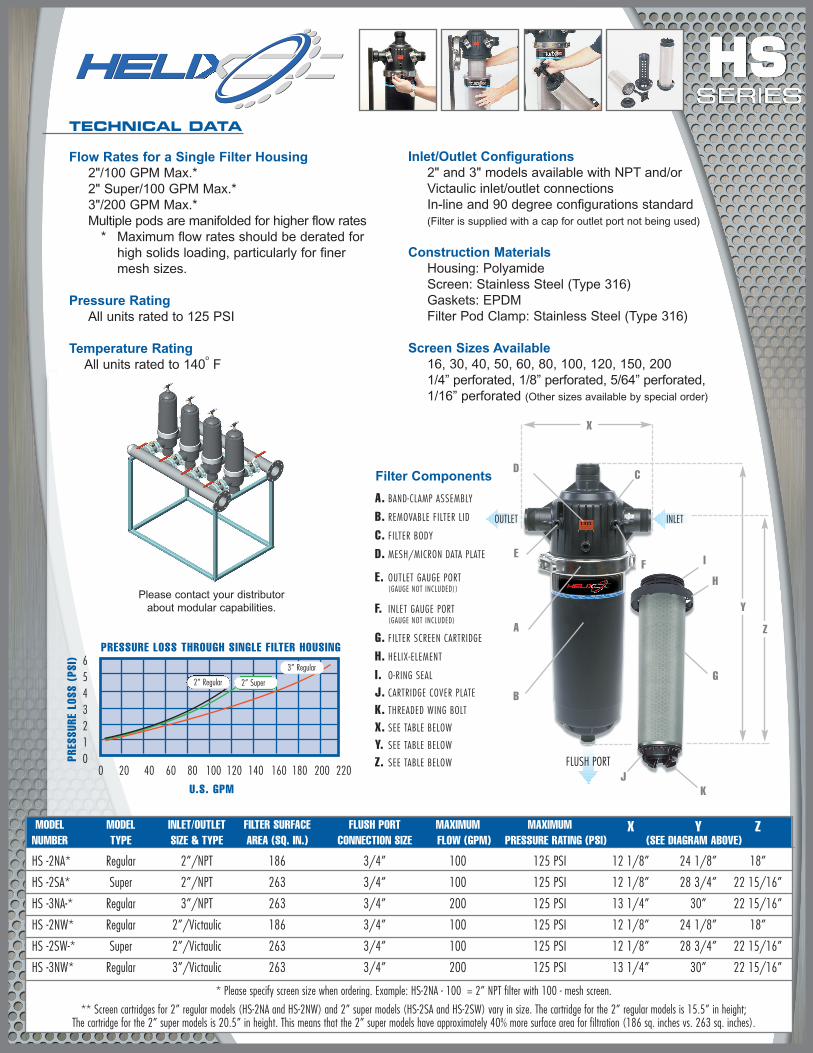
PRESSURE LOSS THROUGH SINGLE FILTER HOUSING
U.S. GPM
PRES
SURE
LOS
S (P
SI)
TECHNICAL DATA
Flow Rates for a Single Filter Housing2"/100 GPM Max.*2" Super/100 GPM Max.*3"/200 GPM Max.*Multiple pods are manifolded for higher flow rates
* Maximum flow rates should be derated for high solids loading, particularly for finer mesh sizes.
Pressure RatingAll units rated to 125 PSI
Temperature RatingAll units rated to 140
oF
Inlet/Outlet Configurations2" and 3" models available with NPT and/or Victaulic inlet/outlet connectionsIn-line and 90 degree configurations standard(Filter is supplied with a cap for outlet port not being used)
Construction MaterialsHousing: PolyamideScreen: Stainless Steel (Type 316)Gaskets: EPDMFilter Pod Clamp: Stainless Steel (Type 316)
Screen Sizes Available16, 30, 40, 50, 60, 80, 100, 120, 150, 2001/4” perforated, 1/8” perforated, 5/64” perforated, 1/16” perforated (Other sizes available by special order)
2” Regular 2” Super
3” Regular
Please contact your distributorabout modular capabilities.
Filter Components
A. BAND-CLAMP ASSEMBLY
B. REMOVABLE FILTER LID
C. FILTER BODY
D. MESH/MICRON DATA PLATE
E. OUTLET GAUGE PORT(GAUGE NOT INCLUDED))
F. INLET GAUGE PORT(GAUGE NOT INCLUDED)
G. FILTER SCREEN CARTRIDGE
H. HELIX-ELEMENT
I. O-RING SEAL
J. CARTRIDGE COVER PLATE
K. THREADED WING BOLT
X. SEE TABLE BELOW
Y. SEE TABLE BELOW
Z. SEE TABLE BELOW
A
E
B
D
I
H
G
JK
C
F
Y
Z
INLETOUTLET
FLUSH PORT
X


