Download - 01079 flexcon

series 556 568 5557
Materials:Body: steel steel steelMembrane: SBR 8–33 l, butyl 2–8 l, butyl
50-500 l, EPDMType of membrane: diaphragm bladder (can be replaced bladder
for volumes from 60 to 500 l)Pipe connection: galvanised steel galvanised steel galvanised steelProtection for pipe connection: - 8–33 l, plastic insert plastic insert
50-500 l, epoxy coatingColour: red blue white
Performance:Medium: water, glycol solutions water waterMax. percentage of glycol: 50% not applicable not applicableMax. working pressure: 6 bar 10 bar 10 barPre-charge pressure: 1,5 bar 2,5 bar 2,5 barSystem working temperature range: -10–120°C -10–70°C -10–100°CMembrane working temperature range: -10–70°C -10–70°C -10–100°CConstruction: conforms to DIN 4807-2 and EN 13831 conforms to DIN 4807-2 and EN 13831 conforms to EN 13831
Application: heating domestic water, hydro-pneumatic well domestic waterconforms to D.M. 6th April 2004, no. 174 conforms to D.M. 6th April 2004, no. 174
Connections:Pipe connection: 8-50 l: 3/4” M (ISO 7-1) 8-33 l: 3/4” M (ISO 228-1) 2 l: 1/2” M (ISO 228-1)
80-600 l: 1” M (ISO 7-1) 50-100 l: 1” M (ISO 228-1) 5 and 8 l: 3/4” M (ISO 228-1)200-500 l: 1 1/4” M (ISO 228-1)
Technical specifications
Expansion vessels
556 - 568 - 5557 series
Function
Expansion vessels are devices designed to accommodate theincrease in the volume of water due to the raising of its temperature,both in heating systems and in domestic hot water productionsystems.They are also used as hydro-pneumatic well in domestic waterdistribution systems.
Product range
556 series Welded expansion vessel for heating systems, CE certifiedcapacity (litres): 8, 12, 18, 25, 35, 50, 80, 100, 140, 200, 250, 300, 400, 500, 600
568 series Welded expansion vessel for domestic water systems and hydro-pneumatic well applications, CE certifiedcapacity (litres): 8, 12, 18, 25, 33, 50, 60, 80, 100, 200, 300, 400, 500
5557 series Welded expansion vessel for domestic water systems, CE certified capacity (litres): 2, 5, 8
0045
1370
ACCREDITED
ISO 9001 No. 0003ISO 9001 FM 21654
01079/13 GB

Operating principle
Expansion vessel for heating and domestic water circuitsThe closed expansion vessel with membrane consists of aclosed container divided into two parts by a membrane whichseparates the water from the gas (usually nitrogen) and actsas an expansion accommodator.Following an increasein temperature, anincrease in pressuretakes place in thevessel in relation to thepre-charge pressurewhen cold (fig. 1) untilit reaches the valuecorresponding to themaximum expansion(fig. 2).
Hydro-pneumatic wellThe operating principle of hydro-pneumatic wells is asfollows. The pump, activated by the pressure switch, starts upand the vessel starts to fill. When the pressure reaches thesetting value, the pump stops: the vessel has reached itsmaximum capacity (fig. 1).In case of water request by the user, pressure is used to supplywater to the system and gradually decreases in the periodbetween activation and deactivation of the pumps (fig. 2).
Dimensions
1 2
1 2
1 2
A3/4”3/4”3/4”3/4”
Ø206280280280
H285275345465
A
Ø
H
Litres8121825
Code556008556012556018556025
Mass (kg)
1,72,32,83,5
A3/4”3/4”1”1”1”1”1”
Ø354409480480480634634
H460493565670912760890
Litres355080100140200250
Code556035556050556080556100556140556200556250
Mass (kg)
5,77,59,911,214,536,745,0
A1”1”1”1”
Ø634740740740
H1060107012901530
Ø
H
Litres300400500600
Code556300556400556500556600
Mass (kg)
52,065,079,085,0
A
Ø
H
A3/4”
Ø354
H455
Ø
H
Litres33
Code568033
Mass (kg)
6,6
A
A1”1”1”1”
11/4”11/4”11/4”11/4”
Ø409409480480634634740740
H605740730835970127012451475
Ø
H
Litres506080100200300400500
Code568050568060568080568100568200568300568400568500
Mass (kg)
9,514,016,019,047,053,070,079,0
A3/4”3/4”3/4”3/4”
Ø206280280280
H320310380500
Litres8121825
Code568008568012568018568025
Mass (kg)
1,82,42,83,7
A
A
Ø
H
A1/2”3/4”3/4”
Ø120175230
H240275305
Litres258
Codice555702555705555708
Mass (kg)
1,01,52,1
A
Ø
H
AI
556
556
556
568
568
I130175175175175205205
I
I235245245245
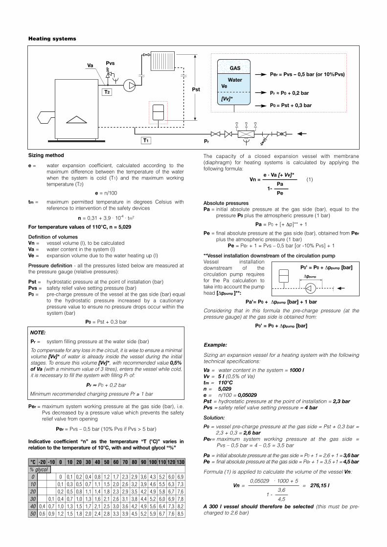
Sizing method
e = water expansion coefficient, calculated according to themaximum difference between the temperature of the waterwhen the system is cold (T1) and the maximum workingtemperature (T2)
e = n/100
tm = maximum permitted temperature in degrees Celsius withreference to intervention of the safety devices
n = 0,31 + 3,9 · 10-4 · tm²
For temperature values of 110°C, n = 5,029
Definition of volumesVn = vessel volume (l), to be calculatedVa = water content in the system (l)Ve = expansion volume due to the water heating up (l)
Pressure definition - all the pressures listed below are measured atthe pressure gauge (relative pressures):
Pst = hydrostatic pressure at the point of installation (bar)Pvs = safety relief valve setting pressure (bar)P0 = pre-charge pressure of the vessel at the gas side (bar) equal
to the hydrostatic pressure increased by a cautionarypressure value to ensure no pressure drops occur within thesystem (bar)
P0 = Pst + 0,3 bar
NOTE:
Pr = system filling pressure at the water side (bar)
To compensate for any loss in the circuit, it is wise to ensure a minimalvolume [Vv]* of water is already inside the vessel during the initialstages. To ensure this volume [Vv]*, with recommended value 0,5%of Va (with a minimum value of 3 litres), enters the vessel while cold,it is necessary to fill the system with filling Pr of:
Pr ≈ P0 + 0,2 bar
Minimum recommended charging pressure Pr ≥ 1 bar
Per = maximum system working pressure at the gas side (bar), i.e.Pvs decreased by a pressure value which prevents the safetyrelief valve from opening
Per = Pvs – 0,5 bar (10% Pvs if Pvs > 5 bar)
Indicative coefficient “n” as the temperature “T (°C)” varies inrelation to the temperature of 10°C, with and without glycol “%”
The capacity of a closed expansion vessel with membrane(diaphragm) for heating systems is calculated by applying thefollowing formula:
e · Va [+ Vv]*Vn = (1)
Pa1-
Pe
Absolute pressuresPa = initial absolute pressure at the gas side (bar), equal to the
pressure P0 plus the atmospheric pressure (1 bar)
Pa = P0 + [+ ∆p]** + 1
Pe = final absolute pressure at the gas side (bar), obtained from Per
plus the atmospheric pressure (1 bar)Pe = Per + 1 = Pvs – 0,5 bar [or -10% Pvs] + 1
**Vessel installation downstream of the circulation pumpVessel installationdownstream of thecirculation pump requiresfor the Pa calculation totake into account the pumphead [∆ppump ]**:
Pa’= P0 + ∆ppump [bar] + 1 bar
Considering that in this formula the pre-charge pressure (at thepressure gauge) at the gas side is obtained from:
P0’ = P0 + ∆ppump [bar]
Example:
Sizing an expansion vessel for a heating system with the followingtechnical specifications:
Va = water content in the system = 1000 lVv = 5 l (0,5% of Va)tm = 110°Cn = 5,029e = n/100 = 0,05029Pst = hydrostatic pressure at the point of installation = 2,3 barPvs =safety relief valve setting pressure = 4 bar
Solution:
P0 = vessel pre-charge pressure at the gas side = Pst + 0,3 bar =2,3 + 0,3 = 2,6 bar
Per= maximum system working pressure at the gas side =Pvs – 0,5 bar = 4 – 0,5 = 3,5 bar
Pa = initial absolute pressure at the gas side = P0 + 1 = 2,6 + 1 = 3,6 barPe = final absolute pressure at the gas side = Per + 1 = 3,5 +1 = 4,5 bar
Formula (1) is applied to calculate the volume of the vessel Vn:
0,05029 · 1000 + 5Vn = = 276,15 l
3,61 -
4,5A 300 l vessel should therefore be selected (this must be pre-charged to 2,6 bar)
Heating systems
°C -20 -10 0 10 20 30 40 50 60 70 80 90 100 110 120 130% glycol0 0 0,1 0,2 0,4 0,8 1,2 1,7 2,3 2,9 3,6 4,3 5,2 6,0 6,9
10 0,1 0,3 0,5 0,7 1,1 1,5 2,0 2,6 3,2 3,9 4,6 5,5 6,3 7,320 0,2 0,5 0,8 1,1 1,4 1,8 2,3 2,9 3,5 4,2 4,9 5,8 6,7 7,630 0,1 0,4 0,7 1,0 1,3 1,6 2,1 2,6 3,1 3,8 4,4 5,2 6,0 6,9 7,840 0,4 0,7 1,0 1,3 1,5 1,7 2,1 2,5 3,0 3,6 4,2 4,9 5,6 6,4 7,3 8,250 0,6 0,9 1,2 1,5 1,8 2,0 2,4 2,8 3,3 3,9 4,5 5,2 5,9 6,7 7,6 8,5
PvsGAS
WaterVe
[Vv]*
Pst
Per = Pvs – 0,5 bar (or 10%Pvs)
Pr ≈ P0 + 0,2 bar
P0 = Pst + 0,3 bar
Va
T2
T1 Pr
P0’ = P0 + ∆ppump [bar]
∆ppump

Sizing method
T1 = cold water supply temperatureT2 = hot water storage temperaturee = water expansion coefficient, calculated
according to the maximum temperaturedifference between the cold water supply andthe hot water storage
e = nT2/100 – nT1/100
Definition of volumes
Vn = vessel volume (l), to be calculatedVsp = volume of the heated water (l) (inside the
storage)Ve = expansion volume due to the water heating up (l)
Pressure definition - all the pressures listed below aremeasured at the pressure gauge (relative pressures):
P0 = vessel pre-charge pressure at the gas side (bar)Pvs = safety relief valve setting pressure (bar)Par = initial relative pressure (bar) at the water side,
represented by the maximum inlet pressure(setting value of the pressure reducing valve orthe maximum mains supply pressure)
Par = P0
Per = maximum system working pressure (bar) at thegas side (Pvs), decreased by a pressure valuewhich prevents the safety relief valve fromopening.
Per = Pvs – 0,5 bar (10% Pvs if Pvs > 5 bar)
The capacity of a closed expansion vessel withmembrane (diaphragm) for domestic water systems withstorage is calculated by applying the following formula:
e · VspVn = (2)
Pa1-
Pe
Absolute pressures
Pa = initial absolute pressure at the gas side (bar),equal to the maximum inlet pressure Par +atmospheric pressure (1 bar). In practice this isthe cold preset pressure of the vessel increasedby 1 bar.
Pa = Par + 1 = P0 + 1
Pe = final absolute pressure at the gas side (bar),obtained from the maximum relative systemworking pressure Per + atmospheric pressure (1bar).
Pe = Per + 1
Indicative coefficient “n” as the temperature“T (°C)” varies in relation to the temperature of 10°C, withoutglycol
Example:
Sizing an expansion vessel for a domestic water system with thefollowing technical specifications:
Vsp = volume of the heated water (storage) = 600 lT1 = cold water supply temperature = 10°CT2 = hot water storage temperature = 80°CPar = initial pressure at the water side = 3,5 barPvs = safety relief valve setting pressure = 6 bar
Solution:
From the table of “n” coefficient values we can see:
for T1 = 10°C -> nT1 = 0,1 for T2 = 80°C -> nT2 = 2,9 therefore“e” for ∆T = 70°C is obtained from:
e = (2,9/100) - (0,1/100) = 0,028
P0 = vessel pre-charge pressure at the gas side = Par = 3,5 barPer = maximum system working pressure at the gas side
= Pvs – 0,5 bar = 6 – 0,5 = 5,5 bar
Pa = initial absolute pressure at the gas side = Par + 1 = 3,5 +1= 4,5 bar
Pe = final absolute pressure at the gas side = Per + 1 = 5,5 +1= 6,5 bar
Formula (2) is applied to calculate the volume of the vessel Vn:
0,028 · 600Vn = = 54,54 l
4,51-
6,5
A 60 l vessel should therefore be selected (this must bepre-charged to 3,5 bar)
Domestic water systems a aaa aa°C 0 10 20 30 40 50 60 70 80 90n 0 0,1 0,2 0,4 0,8 1,2 1,7 2,3 2,9 3,6
Per = Pvs – 0,5 bar (or 10%Pvs)
P0 = ParPvs
Vsp
Par
GAS
WaterVe
T1
T2

Construction details
The expansion vessels are supplied preset with nitrogen. The pre-charge pressure can be modified with compressed air.
Vessel specifications fordomestic water systems
Gas valve position
For 8 to 50 l vessels, the topcap (1) can be removedmanually and protects the gaspre-charging valve (2) used tochange or restore the pre-charge pressure.
For 80 to 500 l vessels, the gaspresetting valve with protectioncover is positioned at the side(3).
Replaceable membrane
The internal membrane can bereplaced in 60 to 500 litremodels.
Bladder membrane in 80 to500 l vessels
In this range of vessels, theinternal membrane is drilled ontop and rests on the internalsupport (4). A 1/2” maleconnection (5) with cap offerscontact with the water containedinside.
Reference standards
The reference European standard is Directive97/23/EC, also known as P.E.D. (Pressure EquipmentDirective) which until 29.05.2002 coexisted with theItalian standard.Caleffi 556 - 568 series expansion vessels are CEmarked and a declaration of conformity is available.
Installation
It is advisable to install expansion vessels on the pipecontaining the lowest temperature water. For heatingsystems, the correct installation should be on the returnpipe.
If the temperature at the point of installation (1) causesthe vessel to reach a temperature over 70°C, it isadvisable to adopt suitable system devices, such as anintermediate through-vessel.
For domestic watersystems, the correctinstallation should beon the incoming coldwater supply pipe.
Example:
Sizing a hydro-pneumatic well with membrane for anetwork with the following technical specifications:
Gpr = 3,4 l/sPmin = 5 barPmax = 6 barPump power P = 1,5 kW
Solution:Formula (3) is applied to calculate the volume of thevessel Vn:
A 300 l vessel should therefore be selected.
Sizing method
Vn = volume of the vessel (hydro-pneumatic well) (l)Gpr = design flow rate (l/s)Pmin = minimum pressure rise (bar), equal to the minimum
pressure switch trigger valuePmax = maximum pressure rise (bar), equal to the maximum
pressure switch trigger valuea = maximum number of hourly pump interventions (h-1)
a = 30 for pump power < 3 kWa = 25 for pump power 3–5 kWa = 20 for pump power 5–7 kWa = 15 for pump power 7–10 kWa = 10 for pump power > 10 kW
Hydro-pneumatic well with membrane The capacity of an expansion vessel to be used ashydro-pneumatic well with membrane is calculated withthe following formula:
Gpr · 60 Pmax + 1Vn = 6 · ·
a Pmax - Pmin
3,4 · 60 6 + 1Vn = 6 · · = 285,6 l
30 6 - 5
Pmin P
1 1
3
4
2
1
T<70°C
5
(3)

Caleffi S.p.A. S.R. 229 n. 25 · 28010 Fontaneto d’Agogna (NO) · Italy Tel. +39 0322 8491 · Fax +39 0322 [email protected] · www.caleffi.com © Copyright 2013 Caleffi
We reserve the right to make changes and improvements to the products and related data in this publication, at any time and without prior notice.
556 seriesWelded expansion vessel for heating systems, CE certified. Connection 3/4” (3/4” from 8 to 50 l and 1” from 80 to 600 l) M (ISO 7-1).Steel body. SBR diaphragm membrane. Galvanised steel connection to pipe. Red colour. Medium water and glycol solutions;maximum percentage of glycol 50%. Maximum working pressure 6 bar. Pre-charge pressure 1,5 bar. System working temperaturerange -10–120°C; membrane working temperature range -10–70°C.
568 seriesWelded expansion vessel for domestic water systems and hydro-pneumatic well applications, CE certified. Connection 3/4” (3/4”from 8 to 33 l, 1” from 50 to 100 l and 1 1/4” from 200 to 500 l) M (ISO 228-1). Steel body. Bladder membrane; in butyl (from 8 to 33l) or in EPDM (from 50 to 500 l; replaceable for volumes from 60 to 500 l). Galvanised steel connection to pipe. Protection forconnection to pipe: plastic insert (8 to 33 l) or epoxy coating (50 to 500 l). Blue colour. Medium water. Maximum working pressure10 bar. Pre-charge pressure 2,5 bar. System working temperature range -10–70°C; membrane working temperature range -10–70°C.
5557 seriesWelded expansion vessel for domestic water systems, CE certified. Connection 1/2” (1/2” 2 l; 3/4” 5 and 8 l) M (ISO 228-1). Steelbody. Bladder membrane in butyl. Galvanised steel connection to pipe. Protection for connection to pipe, plastic insert. Whitecolour. Medium water. Maximum working pressure 10 bar. Pre-charge pressure 2,5 bar. System working temperature range-10–100°C; membrane working temperature range -10–100°C.
SPECIFICATION SUMMARY
Accessories
558050558060558070
3/4”1”1 1/4”
5580Shut-off ball valve for expansionvessels, with drain cock for domesticwater circuit.Max. working pressure: 6 bar.Max. working temperature: 85°C.
Application diagram for 5580 series shut-off valve on domesticwater vessel
Code
Vessel preset check
For the system to work properly, the vessel pre-charge value (at thegas side) must be checked regularly. The 5580 series valve* allowschecking without having to drain the entire system, using thefollowing method:A) Close the shut-off valve (1) after removing the sealB) Drain the vessel (2)C) Check the pre-charge value using the 5560 series pressure
gauge (3)
Once the vessel has been checked (procedures in steps A, B and C),the pre-charging pressure may be restored as necessary using the gaspre-charging valve (4).
* The 5580 series valve is sealed (5) to prevent tampering orunauthorised operations.
1
5
3
2
4

![Flamco Türkçe Katalog 2012 · 2018. 10. 5. · flexcon genle fpe wannlar ¹uÙq wdq w p s ¹uÙqohulpl]lq wdvdu p yh whnqln Ó]hoolnohulql gh l fwluph kdnn p ] vdno g u 1 flexcon](https://cdn.vdocuments.site/doc/165x107/60eae979a1b7c9653975b096/flamco-trke-katalog-2012-2018-10-5-flexcon-genle-fpe-wannlar-uq-wdq.jpg)


