
Hoshizaki
“A Superior Degreeof Reliability”
www.hoshizaki.com
ModelsKM-1301SAH/3, SWH/3, SRH/3KM-1400SWH-M, SWH3-MKM-1601SAH/3, SWH/3, SRH/3KM-1900SAH/3, SWH/3, SRH/3KM-2100SWH3, SRH3KM-2500SWH3, SRH3KMH-2000SWH/3, SRH/3
Stackable Crescent Cuber
Hoshizaki America, Inc.
SERVICE MANUAL
Number: 73197Issued: 8-16-2013Revised: 7-7-2015
2
WARNINGOnly qualified service technicians should install and service the appliance. To obtain the name and phone number of your local Hoshizaki Certified Service Representative, visit www.hoshizaki.com. No service should be undertaken until the technician has thoroughly read this Service Manual. Failure to service and maintain the appliance in accordance with this manual will adversely affect safety, performance, component life, and warranty coverage and may result in costly water damage. Proper installation is the responsibility of the installer. Product failure or property damage due to improper installation is not covered under warranty.
Hoshizaki provides this manual primarily to assist qualified service technicians in the service of the appliance.
Should the reader have any questions or concerns which have not been satisfactorily addressed, please call, send an e-mail message, or write to the Hoshizaki Technical Support Department for assistance.
Phone: 1-800-233-1940; (770) 487-2331Fax: 1-800-843-1056; (770) 487-3360
E-mail: [email protected]
HOSHIZAKI AMERICA, INC.618 Highway 74 SouthPeachtree City, GA 30269Attn: Hoshizaki Technical Support Department
Web Site: www.hoshizaki.com
NOTE: To expedite assistance, all correspondence/communication MUST include the following information:
• Model Number
• Serial Number
• Complete and detailed explanation of the problem.

3
CONTENTSImportant Safety Information ................................................................................................. 6I. Construction and Water/Refrigeration Circuit Diagram ....................................................... 8
A. KM Construction............................................................................................................ 81. Air-Cooled Models (SAH/3) ...................................................................................... 82. Water-Cooled Models (SWH/3/-M) .......................................................................... 93. Remote Models (SRH/3) ....................................................................................... 10
B. KMH Construction ........................................................................................................111. Water-Cooled Models (SWH/3) ...............................................................................112. Remote Models (SRH/3) ....................................................................................... 12
C. Bin Control .................................................................................................................. 131a. Single Thermostatic Bin Control .......................................................................... 131b. Stacked Thermostatic Bin Control ....................................................................... 132a. Single Mechanical Bin Control............................................................................. 142b. Stacked Mechanical Bin Control .......................................................................... 14
D. Water/Refrigeration Circuit Diagram ............................................................................ 151. Air-Cooled Models (SAH/3) .................................................................................... 152. Water-Cooled Models (SWH/3/-M) ........................................................................ 163a. Remote Models (SRH/3) Except KM-2500SRH3 ................................................ 173b. Remote Models (SRH3) KM-2500SRH3 ............................................................. 18
II. Sequence of Operation and Service Diagnosis ............................................................... 19A. Sequence of Operation Flow Chart ............................................................................. 19
1. "E" and "G" Control Board without Harvest Pump Timer Operation ....................... 192. "G" Control Board with Harvest Pump Timer Operation ....................................... 203a. Thermostatic Bin Control Shutdown .................................................................... 213b. Mechanical Bin Control Shutdown ....................................................................... 22
B. Service Diagnosis ....................................................................................................... 231. "E" and "G" Control Board without Harvest Pump Timer Diagnosis ....................... 242. "G" Control Board with Harvest Pump Timer Diagnosis ........................................ 29
C. Control Board Check ................................................................................................... 35D. Bin Control Check ....................................................................................................... 36
1. Thermostatic Bin Control Check ............................................................................. 362. Mechanical Bin Control Check ............................................................................... 37
E. Float Switch Check and Cleaning ............................................................................... 391. Float Switch Check ................................................................................................ 392. Float Switch Cleaning ............................................................................................ 40
F. Thermistor Check ......................................................................................................... 41G. Diagnostic Tables ........................................................................................................ 42
IMPORTANTThis manual should be read carefully before the appliance is serviced. Read the warnings and guidelines contained in this manual carefully as they provide essential information for the continued safe use, service, and maintenance of the appliance. Retain this manual for any further reference that may be necessary.

4
III. Controls and Adjustments ............................................................................................... 46A. Control Board Layout .................................................................................................. 47
1. "E" Control Board .................................................................................................. 472. "G" Control Board ................................................................................................. 48
B. LED Lights and Audible Alarm Safeties ....................................................................... 491. "E" Control Board .................................................................................................. 492. "G" Control Board ................................................................................................. 50
C. Settings and Adjustments ............................................................................................ 511. Default Dip Switch Settings .................................................................................... 51
a) "E" and "G" Control Board without Harvest Pump Timer Operation ................. 51b) "G" Control Board with Harvest Pump Timer Operation ................................... 52c) "G" Control Board S5 Dip Switch ..................................................................... 52
2. Harvest Timer (S4 dip switch 1 & 2) ...................................................................... 523. Pump-Out Timer (S4 dip switch 3 & 4) .................................................................. 534. Pump-Out Frequency Control (S4 dip switch 5 & 6) .............................................. 545. Bin Control Selector or Harvest Pump Timer Operation (S4 dip switch 7) ............. 54
a) Bin Control Selector: "E" Control Board ............................................................ 54b) Harvest Pump Timer: "G" Control Board ........................................................... 55
6. Factory Use (S4 dip switch 8) ................................................................................ 557. Freeze Timer (S4 dip switch 9 & 10) ....................................................................... 558. Float Switch Selector (S5 dip switch 1): "G" Control Board ................................... 569. Refill Counter (S5 dip switch 2 through 5): "G" Control Board ............................... 56
D. Control Switch ............................................................................................................. 56IV. Refrigeration Circuit and Component Service Information.............................................. 57
A. Refrigeration Circuit Service Information .................................................................... 57B. Component Service Information .................................................................................. 60C. Water Regulating Valve Adjustment (water-cooled models) ........................................ 61
V. Maintenance .................................................................................................................... 62VI. Preparing the Icemaker for Periods of Non-Use ............................................................. 63VII. Disposal ......................................................................................................................... 65VIII. Technical Information .................................................................................................... 66
A. Specification and Performance Data ........................................................................... 661. KM-1301SAH ......................................................................................................... 662. KM-1301SAH3 ....................................................................................................... 673. KM-1301SWH ....................................................................................................... 684. KM-1301SWH3 ..................................................................................................... 695. KM-1301SRH with URC-14F ................................................................................. 706. KM-1301SRH3 with URC-14F ............................................................................... 717. KM-1400SWH-M .................................................................................................... 728. KM-1400SWH3-M ................................................................................................. 739. KM-1601SAH ..........................................................................................................7410. KM-1601SAH3 ..................................................................................................... 7511. KM-1601SWH ....................................................................................................... 7612. KM-1601SWH3 .................................................................................................... 7713. KM-1601SRH with URC-21F Auxiliary Codes: R-0, R-1, and some S-1 .............. 7814. KM-1601SRH with URC-21F Auxiliary Codes: some S-1 and S-2 and Later ...... 7915. KM-1601SRH with URC-22F Auxiliary Codes: S-2 and Later .............................. 80
5
16. KM-1601SRH3 with URC-21F Auxiliary Codes: R-0, R-1, and some S-1 ............ 8117. KM-1601SRH3 with URC-21F Auxiliary Codes: some S-1 and S-2 and Later ..... 8218. KM-1601SRH3 with URC-22F Auxiliary Codes: S-2 and Later ............................ 8319. KM-1900SAH ....................................................................................................... 8420. KM-1900SAH3 ..................................................................................................... 8521. KM-1900SWH ...................................................................................................... 8622. KM-1900SWH3 .................................................................................................... 8723. KM-1900SRH with URC-21F ............................................................................... 8824. KM-1900SRH with URC-22F ............................................................................... 8925. KM-1900SRH3 with URC-21F ............................................................................. 9026. KM-1900SRH3 with URC-22F ............................................................................. 9127. KM-2100SWH3 .................................................................................................... 9228. KM-2100SRH3 with URC-22F ............................................................................. 9329. KM-2500SWH3 ................................................................................................... 9430. KM-2500SRH3 with URC-23F ............................................................................. 9531. KMH-2000SWH ................................................................................................... 9632. KMH-2000SWH3 ................................................................................................. 9733. KMH-2000SRH with URC-22F ............................................................................ 9834. KMH-2000SRH3 with URC-22F .......................................................................... 99
B. Wiring Diagrams ........................................................................................................ 1001. "E" and "G" Control Board Schematics without Harvest Pump Timer Relays ..... 100
a) KM-1601SWH, KM-1601SRH, KM-1900S_H, KMH-2000S_H ........................ 100b) KM-1601SWH3, KM-1601SRH3, KM-1900S_H3, KM-2100S_H3, KM-2500S_H3, KMH-2000S_H3 .....................................................................101
2. "G" Control Board Schematics with Harvest Pump Timer Relays ....................... 102a) KM-1301S_H T-0, U-0 ..................................................................................... 102b) KM-1301S_H U-1 to D-0 ................................................................................. 103c) KM-1301SAH and KM-1301SWH D-1 to E-1................................................... 104d) KM-1301SRH D-1 to E-0 ................................................................................. 105e) KM-1301SRH E-1 and Later ........................................................................... 106f) KM-1400SWH-M .............................................................................................. 107g) KM-1601SAH E-0 and Earlier ......................................................................... 108h) KM-1601SAH E-1 and Later ........................................................................... 109i) KM-1301S_H3 T-0, U-0 .....................................................................................110j) KM-1301S_H3 U-1 to E-0 and KM-1601SAH3 A-0 to E-0 ................................. 111k) KM-1301S_H3 E-1 and KM-1601SAH3 E-1 and Later .....................................112l) KM-1400SWH3-M .............................................................................................113

6
Important Safety InformationThroughout this manual, notices appear to bring your attention to situations which could result in death, serious injury, damage to the appliance, or damage to property.
WARNING Indicates a hazardous situation which could result in death or serious injury.
NOTICE Indicates a situation which could result in damage to the appliance or property.
IMPORTANT Indicates important information about the use and care of the appliance.
WARNINGThe appliance should be destined only to the use for which it has been expressly conceived. Any other use should be considered improper and therefore dangerous. The manufacturer cannot be held responsible for injury or damage resulting from improper, incorrect, and unreasonable use. Failure to service and maintain the appliance in accordance with this manual will adversely affect safety, performance, component life, and warranty coverage and may result in costly water damage.To reduce the risk of death, electric shock, serious injury, or fire, follow basic precautions including the following:
• Only qualified service technicians should install and service this appliance.
• The appliance must be installed in accordance with applicable national, state, and local codes and regulations. Failure to meet these code requirements could result in death, electric shock, serious injury, fire, or damage to the appliance.
• Electrical connection must be hard-wired and must meet national, state, and local electrical code requirements. Failure to meet these code requirements could result in death, electric shock, serious injury, fire, or damage.
• The icemaker requires an independent power supply of proper capacity. See the nameplate for electrical specifications. Failure to use an independent power supply of proper capacity can result in a tripped breaker, blown fuse, damage to existing wiring, or component failure. This could lead to heat generation or fire.
• THE ICEMAKER MUST BE GROUNDED. Failure to properly ground the icemaker could result in death or serious injury.
• To reduce the risk of electric shock, do not touch the control switch with damp hands.
• Move the control switch to the "OFF" position and turn off the power supply before servicing. Lockout/Tagout to prevent the power supply from being turned back on inadvertently.
• Do not make any alterations to the appliance. Alterations could result in electric shock, serious injury, fire, or damage.
7
WARNING, continued• The appliance is not intended for use by persons (including children) with reduced
physical, sensory, or mental capabilities, or lack of experience and knowledge, unless they have been given supervision or instruction concerning use of the appliance by a person responsible for their safety.
• Children should be properly supervised around the appliance.
• Do not climb, stand, or hang on the appliance or allow children or animals to do so. Serious injury could occur or the appliance could be damaged.
• Do not use combustible spray or place volatile or flammable substances near the appliance. They might catch fire.
• Keep the area around the appliance clean. Dirt, dust, or insects in the appliance could cause harm to individuals or damage to the appliance.
Additional Warning for Remote Models
• THE REMOTE CONDENSER UNIT MUST BE GROUNDED. The power supply and ground connection to the remote condenser unit are supplied from the icemaker. Failure to properly ground the remote condenser unit could result in death or serious injury.
• Wire routing (conduit) and disconnect (if required) must meet national, state, and local electrical code requirements. Failure to meet these code requirements could result in death, electric shock, serious injury, fire, or damage.
• Move the icemaker control switch to the "OFF" position and turn off the power supply to the icemaker before servicing the remote condenser unit. Lockout/Tagout to prevent the power supply from being turned back on inadvertently.
NOTICE• Follow the instructions in this manual carefully to reduce the risk of costly water
damage.
• In areas where water damage is a concern, install in a contained area with a floor drain.
• Install the appliance in a location that stays above freezing. Normal operating ambient temperature must be within 45°F to 100°F (7°C to 38°C).
• Do not leave the appliance on during extended periods of non-use, extended absences, or in sub-freezing temperatures. To properly prepare the appliance for these occasions, follow the instructions in "VI. Preparing the Icemaker for Periods of Non-Use."
• Do not place objects on top of the appliance.
• The dispenser unit/ice storage bin is for ice use only. Do not store anything else in the dispenser unit/ice storage bin.

8
I. Construction and Water/Refrigeration Circuit Diagram
A. KM Construction
1. Air-Cooled Models (SAH/3)
Evaporator Assembly
Spray Tubes
Inlet Water Valve
Water Supply Inlet
Hot Gas Valve
Junction Box
Condenser
Check Valves(refrigeration)
Control Box
Drier
Transformer Box (KM-1301SAH Auxiliary Code D-1 and Later and All 3 phase model)
Control Switch
Thermostatic Bin Control
Compressor
Cleaning Valve
Float Switch
Water Pump
Check Valve (water)
Thermostatic Expansion Valves
Liquid Line Valve
Fan Motor
Fan Blade
Low-Side Service Valve
High-Side Service Valve
Model Shown: KM-1301SAH3
High-Pressure Switch

9
Evaporator Assembly
Spray TubesInlet Water Valve
Water Supply Inlet
Hot Gas Valve
Junction Box
Water Regulating Valve
Check Valves(refrigeration)
Control Box
Liquid Line Valve
Drier
Control Switch
Bin Control Thermostat
Compressor
Cleaning Valve
Float Switch
Water Pump
Check Valve (water)
Thermostatic Expansion Valves
Water-Cooled Condenser
Low-Side Service Valve
High-Side Service Valve
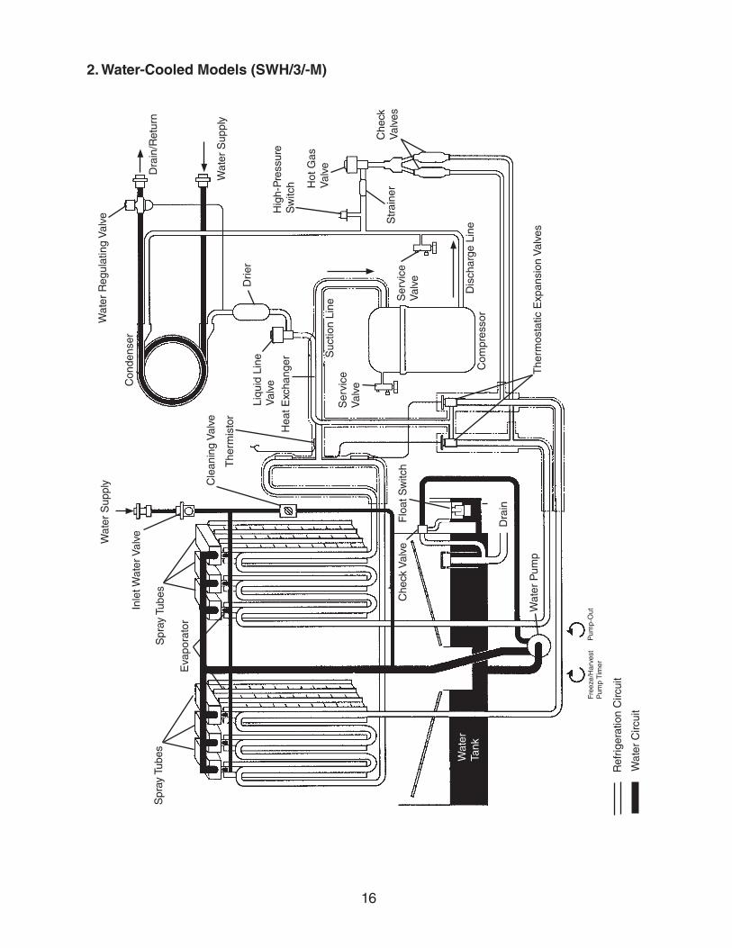
2. Water-Cooled Models (SWH/3/-M)
Model Shown: KM-1301SWH3
Transformer Box (KM-1301SWH Auxiliary Code D-1 and Later and All 3 phase model)

10
Evaporator Assembly
Spray Tubes
Inlet Water Valve
Water Supply Inlet
Hot Gas Valve
Junction Boxes
Receiver
Check Valves(refrigeration)
Control Box
Liquid Line Valve
Drier
Control Switch
Bin Control Thermostat
Compressor
Cleaning Valve
Float Switch
Water Pump
Check Valve (water)
Thermostatic Expansion Valves
Low-Side Service Valve
High-Side Service Valve
High-Side Liquid Service Valve
Access Valve
3. Remote Models (SRH/3)
Model Shown: KM-1301SRH3
Note: KM-2500SRH3 Includes Headmaster (C.P.R.)
Transformer Box (KM-1301SRH Auxiliary Code D-1 and Later and All 3 phase model)
11
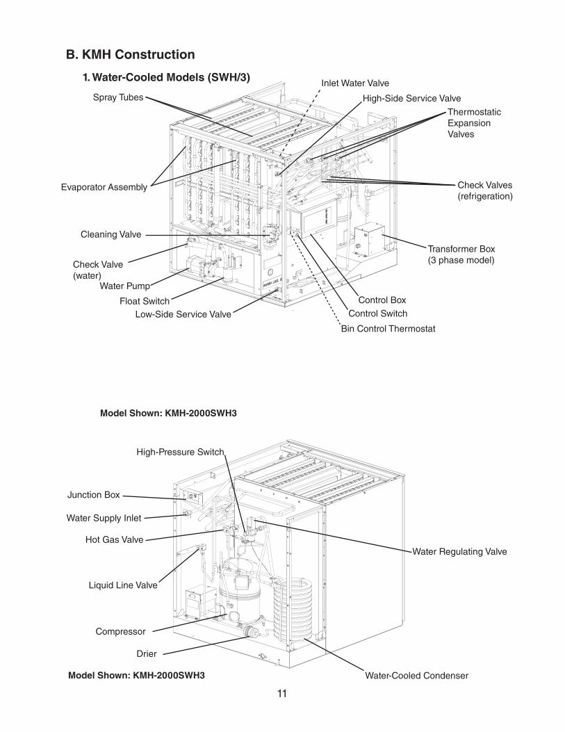
B. KMH Construction
1. Water-Cooled Models (SWH/3)
Evaporator Assembly
Spray Tubes
Inlet Water Valve
Float Switch
Water Pump
Water Supply Inlet
Junction Box
Water Regulating Valve
Check Valves(refrigeration)
Control Box
Liquid Line Valve
Drier
Transformer Box(3 phase model)
Control Switch
Bin Control Thermostat
Compressor
Cleaning Valve
Thermostatic Expansion Valves
Water-Cooled Condenser
Low-Side Service Valve
High-Side Service Valve
Hot Gas Valve
High-Pressure Switch
Check Valve(water)
Model Shown: KMH-2000SWH3
Model Shown: KMH-2000SWH3

12
2. Remote Models (SRH/3)
Evaporator Assembly
Spray Tubes Inlet Water Valve
Float Switch
Water Pump
Water Supply Inlet
Junction Box
Check Valves(refrigeration)
Control Box
Liquid Line Valve
Drier
Transformer Box (3 phase model)
Control Switch
Bin Control Thermostat
Compressor
Cleaning Valve
Thermostatic Expansion Valves
Receiver
Low-Side Service Valve
High-Side Service Valve
Hot Gas Valve
High-Pressure Switch
Check Valve (water)
Model Shown: KMH-2000SRH3
Model Shown: KMH-2000SRH3

13
Bin Control Bulb Holder
Z Bracket Used for Hoshizaki B-1300, B-1500, B-1650, and Non-Hoshizaki Ice Stoarage Bin
C. Bin Control
1a. Single Thermostatic Bin Control
1b. Stacked Thermostatic Bin Control
Bin Control Bulb Holder EBin Control Bulb Holder FBin Control Bulb Holder GSpacer
Bin Control Bulb Holder C
Bin Control Extension Bracket
Silicone Hose
Z Bracket Used for Hoshizaki B-1300, B-1500, B-1650, and Non-Hoshizaki Ice Stoarage Bin
Bin Control Bulb Holder EBin Control Bulb Holder FBin Control Bulb Holder GSpacer
Bin Control Bulb Holder C
Bin Control Extension Bracket
Silicone Hose
Upper Bin Control Bulb Holder
Lower Bin Control Bulb Holder
Lower Bin Control Bulb Holder
Upper Bin Control Bulb Holder

14
Upper Unit Wire Harness Connector B (not used)
Bin Control Cable Bracket
Control Board Red K4 Connector
Upper Unit Wire Harness
Wire Saddle
Lower Unit Wire Harness Connector B to Upper Unit Wire Harness Connector A
Lower Unit Wire Harness
Control Board Red K4 Connector
Upper Unit Connection Overview Upper Unit Connection Detail
See "II.D.1. Dispenser Unit/Ice Storage Bin and Icemaker Setup" and "II.D.2. Bin Control Installation" for the Lower Unit Connection
Control Board Red K4 Connector
Lower Unit Wire Harness Connector B
Upper Unit Wire Harness Connector A
Upper Unit Wire Harness Connector B (not used)
Wire Harness Connector A
Bin Control Cable Connector
Connection Detail
Control Board Red K4 Connector
Bin Control AssemblyThumbscrews
Bin Control Bracket
Bin Control Cable Bracket
Control Board Red K4 Connector
Wire Harness
Wire Saddle
Bin Control Cable
Bin Control Cable Connector to Wire Harness Connector A
Wire Harness Connector B (for upper unit)
Mechanical Bin Control Connection Overview
Wire Harness Connector B (for upper unit)
2a. Single Mechanical Bin Control
2b. Stacked Mechanical Bin Control

15
D. Water/Refrigeration Circuit Diagram
1. Air-Cooled Models (SAH/3)W
ater
Sup
ply
Cle
anin
g V
alve
Flo
at S
witc
h
Dra
in
Che
ck V
alve
The
rmos
tatic
Exp
ansi
on V
alve
s
Com
pres
sor
Hot
Gas
V
alve
Che
ck
Val
ves
Hig
h-P
ress
ure
Sw
itch
Str
aine
r
Drie
r
Con
dens
erE
vapo
rato
r
Ser
vice
V
alve
Dis
char
ge L
ine
Suc
tion
Line
Wat
er P
ump
The
rmis
tor
Spr
ay T
ubes
Inle
t Wat
er V
alve
Pum
p-O
ut
Wat
er
Tank
Ser
vice
V
alve
Ref
riger
atio
n C
ircui
t
Wat
er C
ircui
t
Liqu
id L
ine
Val
ve
Spr
ay T
ubes
Fan
Hea
t Exc
hang
er
Free
ze/H
arve
st
Pum
p T
imer
16
2. Water-Cooled Models (SWH/3/-M)
Wat
er S
uppl
y Cle
anin
g V
alve
Flo
at S
witc
h
Dra
in
Che
ck V
alve
The
rmos
tatic
Exp
ansi
on V
alve
s
Com
pres
sor
Hot
Gas
V
alve
Che
ck
Val
ves
Hig
h-P
ress
ure
Sw
itch
Str
aine
r
Drie
r
Con
dens
er
Eva
pora
tor
Ser
vice
V
alve
Dis
char
ge L
ine
Suc
tion
Line
Wat
er P
ump
The
rmis
tor
Spr
ay T
ubes
Inle
t Wat
er V
alve
Pum
p-O
ut
Wat
er
Tank
Ser
vice
V
alve
Ref
riger
atio
n C
ircui
t
Wat
er C
ircui
t
Liqu
id L
ine
Val
ve
Spr
ay T
ubes
Wat
er S
uppl
y
Dra
in/R
etur
n
Wat
er R
egul
atin
g V
alve
Hea
t Exc
hang
er
Free
ze/H
arve
st
Pum
p T
imer

17
3a. Remote Models (SRH/3) Except KM-2500SRH3Condenser Unit with Headmaster (CPR)
Wat
er
Sup
ply
Cle
anin
g V
alve
Flo
at S
witc
h
Dra
in
Che
ck V
alve
Exp
ansi
on V
alve
s
Com
pres
sor
Hot
Gas
V
alve
Che
ck
Val
ves
Hig
h P
ress
ure
Sw
itch
Str
aine
r
Drie
r
Con
dens
er
Eva
pora
tor
Ser
vice
V
alve
Dis
char
ge L
ine
Suc
tion
Line
Wat
er P
ump
The
rmis
tor
Spr
ay T
ubes
Inle
t Wat
er V
alve
Free
ze/H
arve
st
Pum
p T
imer
Pum
p-O
ut
Wat
er
Tank
Ser
vice
V
alve
Ref
riger
atio
n C
ircui
t
Wat
er C
ircui
t
Fan
Hea
dmas
ter
(C.P
.R.)
Liqu
id L
ine
Val
ve
Rec
eive
rFu
sibl
e P
lug
Ser
vice
V
alve
Spr
ay T
ubes
Hea
t Exc
hang
er
KM
-250
0SR
H3:
Hea
dmas
ter
loca
ted
in ic
emak
er

18
3b. Remote Models (SRH3) KM-2500SRH3Condenser Unit without Headmaster (CPR)
Wat
er
Sup
ply
Cle
anin
g V
alve
Flo
at S
witc
h
Dra
in
Che
ck V
alve
Exp
ansi
on V
alve
s
Com
pres
sor
Hot
Gas
V
alve
Che
ck
Val
ves
Hig
h-P
ress
ure
Sw
itch
Str
aine
r
Drie
r
Con
dens
er
Eva
pora
tor
Ser
vice
V
alve
Dis
char
ge L
ine
Suc
tion
Line
Wat
er P
ump
The
rmis
tor
Spr
ay T
ubes
Inle
t Wat
er V
alve
Free
zeP
ump-
Out
Wat
er
Tank
Ser
vice
Val
ve
Ref
riger
atio
n C
ircui
t
Wat
er C
ircui
t
Fan
Hea
dmas
ter
(C.P
.R.)
Liqu
id L
ine
Val
ve
Rec
eive
rFu
sibl
e P
lug
Shu
t-O
ff V
alve
(F
acto
ry U
se O
nly)
Ser
vice
Val
ve

19
II. Sequence of Operation and Service Diagnosis
A. Sequence of Operation Flow Chart
1. "E" and "G" Control Board without Harvest Pump Timer Operation
Co
mp
on
ents
En
erg
ized
wh
en t
he
Co
ntr
ol S
wit
ch is
in t
he
"WA
SH
" P
osi
tio
nT
he "
WA
SH
" po
sitio
n on
the
cont
rol s
witc
h is
use
d w
hen
clea
ning
and
san
itizi
ng th
e ic
emak
er. W
hen
in th
e "W
AS
H"
posi
tion,
pow
er is
sup
plie
d to
the
pum
p m
otor
. With
the
clea
ning
val
ve c
lose
d, th
e cl
eane
r an
d sa
nitiz
er fl
ow o
ver
the
outs
ide
of th
e ev
apor
ator
pla
te a
ssem
bly.
With
the
clea
ning
val
ve o
pen,
the
clea
ner
and
sani
tizer
flow
ove
r bo
th th
e ou
tsid
e an
d th
e in
side
of t
he e
vapo
rato
r pl
ate
asse
mbl
y.
Not
e: C
lose
the
clea
ning
val
ve a
fter
clea
ning
and
san
itizi
ng a
re c
ompl
ete,
oth
erw
ise
the
icem
aker
will
not
res
tart
whe
n th
e co
ntro
l sw
itch
is p
lace
d in
the
"IC
E"
posi
tion.
Leg
end
:B
C–b
in c
ontr
olC
om
p–c
ompr
esso
rF
M–f
an m
otor
FM
R–f
an m
otor
-rem
ote
FS
–floa
t sw
itch
HG
V–h
ot g
as v
alve
L
LV–l
iqui
d lin
e va
lve
PM
–pum
p m
otor
W
V–i
nlet
wat
er v
alve
• M
ax. W
V ti
me:
6 m
in.
• M
ax. h
arve
st ti
me:
20
min
.
FS
che
ck
1 to
3-m
in. h
arve
st
timer
in c
ontr
ol
(S4
dip
switc
h 1
& 2
)
"E"
and
"G
" C
on
tro
l Bo
ard
wit
ho
ut
Har
vest
Pu
mp
Tim
er O
per
atio
n F
low
Ch
art
1. 1
-Min
ute
Fill
Cyc
leC
ycle
S
tep
s
2. H
arve
st C
ycle
The
rmis
tor
in c
ontr
ol
3. F
reez
e C
ycle
• M
in. f
reez
e tim
e: 5
min
.•
Max
. fre
eze
time:
free
ze ti
mer
se
tting
(
S4
dip
switc
h 9
& 1
0) FS
in c
ontr
ol
4. P
um
p-O
ut
Cyc
le•
Fact
ory
set f
or e
very
10
th c
ycle
(
S4
dip
switc
h 5
& 6
)•
Pum
p m
otor
sto
ps fo
r 2
sec.
, the
n re
vers
es
for
10/2
0 se
c. (
S4
dip
switc
h 3
& 4
)
WV
ene
rgiz
ed
FS
ope
n
Co
mp
ene
rgiz
edF
MR
ene
rgiz
edH
GV
ene
rgiz
edW
V e
nerg
ized
The
rmis
tor
tem
pera
ture
re
ache
s 48
°F (
9°C
) (3
.9 k
Ω o
r le
ss).
Har
vest
tim
er s
tart
s (1
to 3
min
.).
FS
ope
n
Co
mp
con
tinue
sF
MR
con
tinue
sF
M e
nerg
ized
LLV
ene
rgiz
ed
PM
ene
rgiz
ed
HG
V d
e-en
ergi
zed
WV
de-
ener
gize
d
FS
clo
sed
Co
mp
con
tinue
sF
MR
con
tinue
sH
GV
ene
rgiz
edP
M d
e-en
ergi
zes
for
2 se
c.,
then
rev
erse
s fo
r 10
/20
sec.
FM
de-
ener
gize
dL
LV d
e-en
ergi
zed
FS
che
ck
Sta
rtup
If F
S is
ope
n, C
omp
stop
s an
d cy
cle
retu
rns
to 1
-min
. fill.
5-m
in. t
imer
in
cont
rol
FS
clo
sed
FS
ope
ns o
r fr
eeze
tim
er
term
inat
es
20
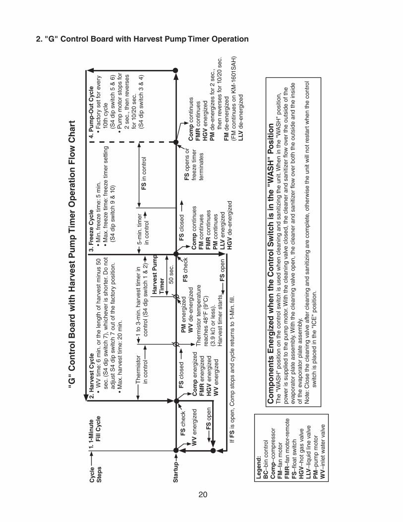
• W
V ti
me:
6 m
in. o
r th
e le
ngth
of h
arve
st m
inus
50
sec.
(S
4 di
p sw
itch
7), w
hich
ever
is s
hort
er. D
o no
t ad
just
S4
dip
switc
h 7
out o
f the
fact
ory
posi
tion.
• M
ax. h
arve
st ti
me:
20
min
.
FS
che
ck
1 to
3-m
in. h
arve
st ti
mer
in
cont
rol (
S4
dip
switc
h 1
& 2
)
Leg
end
: B
C–b
in c
ontr
olC
om
p–c
ompr
esso
rF
M–f
an m
otor
FM
R–f
an m
otor
-rem
ote
FS
–floa
t sw
itch
HG
V–h
ot g
as v
alve
LLV
–liq
uid
line
valv
eP
M–p
ump
mot
orW
V–i
nlet
wat
er v
alve
Co
mp
on
ents
En
erg
ized
wh
en t
he
Co
ntr
ol S
wit
ch is
in t
he
"WA
SH
" P
osi
tio
nT
he "
WA
SH
" po
sitio
n on
the
cont
rol s
witc
h is
use
d w
hen
clea
ning
and
san
itizi
ng th
e un
it. W
hen
in th
e "W
AS
H"
posi
tion,
po
wer
is s
uppl
ied
to th
e pu
mp
mot
or. W
ith th
e cl
eani
ng v
alve
clo
sed,
the
clea
ner
and
sani
tizer
flow
ove
r th
e ou
tsid
e of
the
evap
orat
or p
late
ass
embl
y. W
ith th
e cl
eani
ng v
alve
ope
n, th
e cl
eane
r an
d sa
nitiz
er fl
ow o
ver
both
the
outs
ide
and
the
insi
de
of th
e ev
apor
ator
pla
te a
ssem
bly.
N
ote:
Clo
se th
e cl
eani
ng v
alve
afte
r cl
eani
ng a
nd s
aniti
zing
are
com
plet
e, o
ther
wis
e th
e un
it w
ill n
ot r
esta
rt w
hen
the
cont
rol
s
witc
h is
pla
ced
in th
e "I
CE
" po
sitio
n.
"G"
Co
ntr
ol B
oar
d w
ith
Har
vest
Pu
mp
Tim
er O
per
atio
n F
low
Ch
art
1. 1
-Min
ute
Fill
Cyc
leC
ycle
S
tep
s2.
Har
vest
Cyc
le
The
rmis
tor
in c
ontr
ol
3. F
reez
e C
ycle
• M
in. f
reez
e tim
e: 5
min
.•
Max
. fre
eze
time:
free
ze ti
mer
set
ting
(S4
dip
switc
h 9
& 1
0) FS
in c
ontr
ol
4. P
um
p-O
ut
Cyc
le•
Fact
ory
set f
or e
very
10
th c
ycle
(S
4 di
p sw
itch
5 &
6)
• P
ump
mot
or s
tops
for
2 se
c., t
hen
reve
rses
fo
r 10
/20
sec.
(S
4 di
p sw
itch
3 &
4)
WV
ene
rgiz
ed
FS
ope
n
Co
mp
ene
rgiz
edF
MR
ene
rgiz
edH
GV
ene
rgiz
edW
V e
nerg
ized
The
rmis
tor
tem
pera
ture
re
ache
s 48
°F (
9°C
) (3
.9 k
Ω o
r le
ss).
H
arve
st ti
mer
sta
rts.
FS
ope
n
Co
mp
con
tinue
sF
M c
ontin
ues
FM
R c
ontin
ues
PM
con
tinue
sL
LV e
nerg
ized
HG
V d
e-en
ergi
zed
FS
clo
sed
Co
mp
con
tinue
sF
MR
con
tinue
sH
GV
ene
rgiz
edP
M d
e-en
ergi
zes
for
2 se
c.,
then
rev
erse
s fo
r 10
/20
sec.
FM
de-
ener
gize
d
(FM
con
tinue
s on
KM
-160
1SA
H)
LLV
de-
ener
gize
d
FS
che
ckS
tart
up
If F
S is
ope
n, C
omp
stop
s an
d cy
cle
retu
rns
to 1
-Min
. fill.
5-m
in. t
imer
in
con
trol
FS
clo
sed
FS
ope
ns o
r fr
eeze
tim
er
term
inat
es
50 s
ec.
PM
ene
rgiz
edW
V d
e-en
ergi
zed
Har
vest
Pu
mp
T
imer
2. "G" Control Board with Harvest Pump Timer Operation

21
1. B
in F
ull
W
ithin
10
sec.
afte
r ic
e co
ntac
ts
T
BC
bul
b, ic
emak
er s
huts
dow
n.
Sh
utd
ow
n
and
Res
tart
TB
C
Ope
ratio
n
Ice
cont
acts
TB
C b
ulb
2. Ic
emak
er O
ff
All
com
pone
nts
de
-ene
rgiz
ed.
3. Ic
e L
evel
Lo
wer
ed
No
ice
touc
hing
TB
C b
ulb.
Icem
aker
sta
rts
at
"
1. 1
-Min
ute
Fill
Cyc
le."
TB
C c
lose
dT
BC
ope
nA
ll co
mpo
nent
s de
-ene
rgiz
ed
To 1
. 1-M
inu
te F
ill C
ycle
NO
TE
: "G
" co
ntro
l boa
rd g
reen
"B
C C
LOS
ED
" LE
D
on c
ontin
uous
ly w
hen
the
K4
jum
per
is in
pla
ce.
3a. Thermostatic Bin Control Shutdown
"E"
and
"G
" C
on
tro
l Bo
ard
wit
h T
her
mo
stat
ic B
in C
on
tro
l Sh
utd
ow
n S
equ
ence
Flo
w C
har
t
Leg
end
:B
C–b
in c
ontr
olT
BC
–the
mos
tatic
bin
con
trol

22
"G"
Co
ntr
ol B
oar
d M
ech
anic
al B
in C
on
tro
l Sh
utd
ow
n S
equ
ence
Flo
w C
har
t
1. B
in F
ull
Sh
utd
ow
n D
elay
:•
Fill
Cyc
le–1
5 se
c. a
fter
activ
atio
n.•
Har
vest
Cyc
le–A
t the
end
of t
he h
arve
st c
ycle
, or
up
to
15 s
ec. i
nto
the
free
ze c
ycle
if
a
ctiv
ated
at t
he e
nd o
f the
har
vest
cyc
le.
• Fr
eeze
Cyc
le–
15
sec.
afte
r ac
tivat
ion
if ac
tivat
ed a
t lea
st
1
5 se
c. b
efor
e th
e 5-
min
. sho
rt c
ycle
p
rote
ctio
n tim
er te
rmin
ates
. O
ther
wis
e, a
t the
end
of t
he n
ext h
arve
st c
ycle
.
Sh
utd
ow
n
and
Res
tart
MB
C
Ope
ratio
n
MB
C o
pen
(MB
C a
ctua
tor
padd
le e
ngag
ed)
G
reen
"B
C C
LOS
ED
" LE
D o
ff
Yello
w "
BC
OP
EN
" LE
D o
n
Yello
w "
BC
OP
EN
" LE
D c
ontin
ues.
A
ll co
mpo
nent
s de
-ene
rgiz
ed.
2. Ic
emak
er O
ff
All
com
pone
nts
de-e
nerg
ized
.
3. Ic
e L
evel
Lo
wer
ed Ic
emak
er s
tart
s at
"
1. 1
-Min
ute
Fill
Cyc
le."
MB
C c
lose
d
(MB
C a
ctua
tor
padd
le d
isen
gage
d)
Gre
en "
BC
CLO
SE
D"
LED
on
Ye
llow
"B
C O
PE
N"
LED
off
To 1
. 1-M
inu
te F
ill C
ycle
Leg
end
:B
C–b
in c
ontr
olM
BC
–mec
hani
cal b
in c
ontr
ol
3b. Mechanical Bin Control Shutdown

23
B. Service Diagnosis
WARNING• The appliance should be diagnosed and repaired only by qualified service
personnel to reduce the risk of death, electric shock, serious injury, or fire.
• Risk of electric shock. Control switch in "OFF" position does not de-energize all loads Use extreme caution and exercise safe electrical practices.
• Moving parts (e.g., fan blade) can crush and cut. Keep hands clear.
• Before servicing the appliance, move the control switch to the "OFF" position and turn off the power supply.
• CHOKING HAZARD: Ensure all components, fasteners, and thumbscrews are securely in place after the appliance is serviced. Make sure that none have fallen into the dispenser unit/ice storage bin.
• Make sure all food zones in the appliance and dispenser unit/ice storage bin are clean after service.
The diagnostic procedure is a sequence check that allows you to diagnose the electrical system and components. Before proceeding, check for correct installation, proper voltage per nameplate, and adequate water supply. Check CB using the steps in "II.C. Control Board Check." Check dip switch settings to assure that S4 dip switch 3, 4, 7, 8, 9, 10 and S5 dip switch 1 through 5 ("G" CB) are in the factory default position. S4 dip switch 1, 2, 5, 6 are cleaning adjustments and the settings are flexible. For factory default settings, see "III.C.1. Default Dip Switch Settings."
Note: • When checking high voltage (115VAC), always choose a white (W) neutral wire to establish a good neutral connection.
• On models with a main transformer, the neutral (W) is provided through MT. To confirm a good neutral, check for 60VAC from white (W) neutral to ground (GND). If 60VAC is present, neutral is good. If 60VAC is not present, check 208-230VAC main power supply to MT. If 208-230VAC is present, check MT continuity.
• When checking voltage from the CB K1 connector (10 pin connector), pull CB K1 connector out slightly to allow room for multimeter test leads contact.
1) Turn off the power supply, then access the control box. Move the control switch to the "OFF" position. Clear any ice from TBC.
2) Check that BC is closed and the 115VAC 10A fuse is good.

24
1. "E" and "G" Control Board without Harvest Pump Timer Diagnosis
3) Power On: Turn on the power supply, then move the control switch to the "ICE" position.A 5-sec. delay occurs. • "E" Control Board: CB red "POWER OK" LED turns on.• "G" Control Board: CB red "POWER OK" LED and green "BC CLOSED" LED turn on.
Note: • CB red "POWER" LED remains on unless the 10.5VAC power supply is interrupted (K2 connector).
• Check CB using the steps in "II.C. Control Board Check."
• "G" CB: If yellow "BC OPEN" LED is on, check that CB red K4 jumper is in place.
a) Power On Diagnosis: If CB red "POWER OK" LED is off, confirm closed TBC and 10A fuse is good. If TBC is open, remove ice from bulb and warm bulb in hand. If TBC does not close, replace TBC. See "II.D. Bin Control Check." Check for 115VAC at control switch #1 (BK) to neutral (W) then at control switch #2 (P) to neutral (W). If 115VAC is present on control switch #1 (BK) and not on control switch #2 (P), replace control switch. If 115VAC is present on control switch #2 (P), check for 115VAC at HPS (P) to neutral (W), then HPS (BK) to neutral (W). If 115VAC is present at HPS (P) and not at HPS (BK), HPS is open. See HPS Diagnosis below. If 115VAC is present at HPS (BK), check for 10.5VAC at CB K2 #1 (R) to CB K2 #2 (R). If 10.5VAC is not present, confirm that the cleaning valve interlock switch is closed. Next, check CT continuity. If open, replace CT.
b) HPS Diagnosis: Confirm FM is energized and fan blade turns freely. Confirm condenser coil is not dirty. Confirm that the location meets installation requirements. See the appliance's instruction manual for details. Confirm there are no restrictions in the refrigeration circuit. Harvest Cycle: HGV, strainer, or check valve. Freeze Cycle: FM, FMR, TXV, HM, LLV, WRV, strainer, check valve, drier, damaged line set or fitting, and fan blade for binding. Let refrigeration circuit pressures equalize. If HPS does not reset and pressures are equalized, replace HPS. If pressures are not equalized, reclaim refrigerant and diagnose refrigeration circuit restriction.
4) 1-Minute Fill Cycle – LED 4 is on. WV energizes. After 1 min., CB checks for a closed FS. If FS is closed, harvest cycle begins. If harvest cycle begins (Comp, HGV, and FMR energize), continue to step 5. If FS is open, WV remains energized through additional 1-min. fill cycles until water enters the water tank and FS closes (low water safety protection during initial start up and at the end of each harvest). Diagnosis: Check that water enters the water tank. If not, check that the water supply line shut-off valve is open and screens or external filters are clear. Check for 115VAC at CB K1 #6 (O) to neutral (W). If 115VAC is not present, replace CB. If 115VAC is present, and WV does not energize, check for 115VAC at WV. If 115VAC is present, check coil continuity. If open, replace WV. If the water tank fills, but the appliance fails to start harvest (Comp energized), check for open FS. See "II.E. Float Switch Check and Cleaning." If FS is closed and CB fails to start the harvest cycle after 1 min., replace CB.

25
5) Initial Harvest Cycle – LEDs 1, 4, and 2 are on. WV continues. Comp, FMR, and HGV energize. CB monitors the warming of the evaporator via the thermistor located on the suction line. When the thermistor reaches 48°F (9°C), CB reads 3.9 kΩ from the thermistor and turns harvest termination over to the harvest timer (S4 dip switch 1 & 2). The harvest timer has settings of 60, 90, 120, and 180 sec. The pump-out timer (S4 dip switch 3 & 4) acts in place of the harvest timer during cycles with a pump-out (S4 dip switch 5 & 6). WV remains energized during harvest for a maximum of 6 min. or the length of harvest, whichever is shorter.
a) Comp Diagnosis: Check that evaporator is warming. If not, confirm that Comp energizes. If not, check for 115VAC at CB K1 #1 (V) or #9 (V) to neutral (W). If 115VAC is not present, check for 115VAC at CB K1 #7 (BR) or #10 (BR) to neutral (W). If 115VAC is present at CB #7 (BR) or #10 (BR) and not at CB #1 (V) or #9 (V), replace CB. If 115VAC is present, check for 115VAC at MC solenoid. If 115VAC is present, confirm contacts are closed. If not, replace MC. If MC contacts are closed, check Comp start and run capacitors, Comp start relay, and Comp motor winding.
b) HGV Diagnosis: If Comp is energized and evaporator is not warming, check that HGV energizes and opens. Check for 115VAC at CB K1 #2 (P) to neutral (W). If 115VAC is not present, replace CB. If 115VAC is present, check for 115VAC at HGV coil and check HGV coil continuity. Replace as needed.
c) LLV Diagnosis: Confirm that LLV is de-energized and closed (not bypassing). If energized, replace CB. If de-energized and bypassing, replace LLV.
d) WRV Diagnosis: Confirm WRV is not leaking by.
e) Initial Harvest Cycle Termination Diagnosis: When the thermistor reaches 48°F (9°C), CB reads 3.9 kΩ from the thermistor and turns harvest termination over to the harvest timer (S4 dip switch 1 & 2). Check discharge line temperature. For a thermistor check, see "II.F. Thermistor Check." If 1-min. fill cycle starts after harvest timer terminates, check that FS is clean and operating properly. See "II.E. Float Switch Check and Cleaning." If FS is closed, CB proceeds to the next cycle. If not, replace CB.
Note: The min. total time allowed by CB for a complete harvest cycle is 2 min. Max. harvest time allowed is 20 min.
NOTICE! On models with "G" control board and no harvest pump timer relays, S4 dip switch 7 must remain off. Otherwise, PM energizes in reverse direction the last 50 seconds of harvest and empties water from water tank.
6) Freeze Cycle – LED 1 is on. Comp and FMR continue. PM, FM, and LLV energize. WV and HGV de-energize. Appliance is held in freeze by a 5-min. short cycle protection timer. After 5-min. timer terminates and FS opens, freeze cycle terminates.
a) Freeze Cycle Diagnosis: Confirm Comp and FMR continue. Confirm that PM, FM, and LLV energize. Confirm WRV opens. Next, confirm WV and HGV de-energize. During the first 5 min. of freeze, confirm evaporator is cooling. If not, confirm WV de-energized (not leaking by), HGV de-energized (not bypassing), LLV and FM energize, TXV and HM operate correctly, WRV opens, Comp is efficient, and refrigerant charge is correct. See "VIII.A. Specification and Performance Data."

26
b) Comp and FMR Diagnosis: If Comp and FMR de-energize once freeze begins, check that appliance has not shut off on HPS ("POWER OK" LED off). If so, check "3)b) HPS Diagnosis" above. If "POWER OK" LED is on, check for 115VAC at CB K1 #1 (V) or #9 (V) to neutral (W). If 115VAC is not present and LED 1 is on, replace CB. If 115VAC is present, check for 115VAC at CR or MC coil. If 115VAC is present, check CR or MC coil and contact continuity. Replace as needed. If CR or MC is ok, check Comp external overload, start relay, and start and run capacitors. Next, check Comp motor winding continuity. If Comp is energized but evaporator is not cooling, check for an inefficient Comp. See "VIII.A. Specification and Performance Data." If Comp is energized but FMR is not, check for 115VAC at the FMR junction box. If 115VAC is not present, check icemaker wiring connections. If 115VAC is present, check for voltage at condenser unit. If 115VAC is not present, check field wiring connections. If 115VAC is present, check FMR capacitor, motor winding, and fan blade for binding.
c) WV and HGV Diagnosis: If WV is energized, check for 115VAC at CB K1 #6 (O) to neutral (W). If 115VAC is present after PM energizes, replace CB. If 115VAC is not present, replace WV (bypassing). If HGV did not de-energize, check for 115VAC at CB K1 #2 (P) to neutral (W). If 115VAC is present after PM energizes, replace CB. If 115VAC is not present, replace HGV (bypassing).
d) PM Diagnosis: Confirm water is flowing over evaporator from PM and not WV. If PM de-energizes once freeze begins, check for 115VAC at CB K1 #4 (R) to neutral (W). If 115VAC is not present, replace CB. If 115VAC is present and PM is de-energized, check for 115VAC at control switch #5 (R) to neutral (W). If 115VAC is present at CB K1 #4 (R) and not at control switch #5 (R), check control switch continuity between #5 (R) and #4 (R). Replace as needed. If 115VAC is present at control switch #5 (R) to neutral (W), check PM impeller for binding, PM capacitor, and motor winding continuity.
e) FM and LLV Diagnosis: If FM or LLV does not energize, check for 115VAC at CB K1 #3 (BK) to neutral (W). If 115VAC is not present, replace CB. If 115VAC is present: For FM: check capacitor, motor winding, and blade for binding. For LLV: check coil voltage and continuity.
f) Refrigerant Pressures, HM, and TXV Diagnosis: If evaporator is still not cooling, check refrigerant pressures. See "VIII.A. Specification and Performance Data." Next, check HM operation. If refrigeration pressures are above HM setpoint and HM is bypassing, replace HM. Check TXV for proper operation. Remove TXV bulb and hold it in your hand, refrigerant low-side pressure should rise, place TXV bulb in ice water, refrigerant low-side pressure should drop. A 10 to 15 pound pressure swing between warm and cold conditions indicate a good TXV. If a 10 to 15 pound swing is not present, replace TXV.
g) WRV Diagnosis: WRV is factory set and generally no adjustment is required. If WRV fails to open in freeze, check for proper refrigerant pressures. See "VIII.A. Specification and Performance Data." If refrigerant pressures are correct and WRV does not open, adjust or replace as needed. See "IV.C. Water Regulating Valve Adjustment (water-cooled models)."

27
h) Freeze Termination Diagnosis: After 5 min. in freeze, disconnect CB K5 FS connector. 15 sec. later appliance should switch out of the freeze cycle (15 second delay after FS opens before terminating the freeze cycle). If appliance remains in freeze longer than 15 sec. after FS removed, replace CB. If appliance switches with FS removed but would previously not switch out of freeze with FS connected (long freeze - 3 beep alarm), see "II.E. Float Switch Check and Cleaning."
Note: Normal freeze cycle will last 20 to 40 min. depending on model and conditions. Cycle times and pressures should follow performance data provided in this manual. See "VIII.A. Specification and Performance Data."
i) Short Freeze Cycle Diagnosis: Confirm water tank fills and overflows during 1 min. fill and harvest cycles. If not, check water supply filters, shut-off valve, WV screen. If water tank empties before 5 min. timer terminates and freeze cycle is short, check that CV is not leaking by (water flowing down the potable drain). If CV is leaking by, remove and clean CV, replace rubber seat and spring if necessary. If water tank is full, see "II.E. Float Switch Check and Cleaning" for erratic operating FS.
7) Pump-Out Cycle – LEDs 1, 3, and 2 are on (10/20 second pump-out). Timing of the first pump-out is dependent on CB. "E" CB first pump-out is after the first freeze cycle. "G" CB first pump-out is determined by S4 dip switch 5 & 6. See the table below.
"E" & "G" Control Board Settings 1st Pump-Out
S4 Dip Switch Setting Pump-Out Frequency
"E" Control Board "G" Control BoardNo. 5 No. 6
OFF OFF Every cycle After 1st freeze cycle After 2nd freeze cycle
ON OFF Every 2 cycles After 3rd freeze cycle
OFF ON Every 5 cycles After 6th freeze cycle
ON ON Every 10 cycles After 11th freeze cycle
Comp and FMR continue, HGV energizes. If S4 dip switch 3 & 4 are set to 3 off and 4 on, LED 4 turns on and WV energizes. FM and LLV de-energize. PM stops for 2 sec., then reverses for 10/20 sec. depending on pump-out timer (S4 dip switch 3 & 4) setting. When the pump-out timer terminates, pump-out is complete. The pump-out frequency control (S4 dip switch 5 & 6) is factory set, and generally no adjustment is required. However, the pump-out frequency control can be set to have a pump-out occur every cycle, or every 2, 5, or 10 cycles. For details, see "III.C.4. Pump-Out Frequency Control (S4 dip switch 5 & 6)."
Pump-Out Diagnosis: In the freeze cycle before pump-out (see table above), disconnect CB black K5 connector (FS connector) after 5 min. of freeze. Check that PM stops and re-starts and water is flowing down the drain through CV. If PM does not stop and re-start, check that CB LEDs 1, 3, and 2 are on. If not, replace CB. If LEDs 1, 3, and 2 are on and PM does not energize, check for 115VAC at CB K1 #5 (DBU) to neutral (W). If 115VAC is not present, replace CB. If 115VAC is present, make sure the drain line is not clogged and that CV is clean and operating properly.
Confirm FM and LLV de-energize. If FM or LLV is energized with LEDs 1, 3, and 2 on, replace CB.

28
8) Normal Harvest Cycle – Same as the initial harvest cycle. Return to step 5 above. Note: Appliance continues to cycle until BC is satisfied or power is turned off. The
appliance always restarts at the 1-min. fill cycle.
9) Shutdown: "E" and "G" Control Board When the appliance is running, hold ice in contact with the thermostatic bulb. TBC switch opens within 10 sec., shutting down the appliance. TBC is factory set, and generally no adjustment is required. However, adjustment may be needed in some conditions, particularly at higher altitude locations. Diagnosis: See "II.D. Bin Control Check." NOTICE! Do not adjust S4 dip switch 7 out of the factory default position. This dip switch must be left in the factory default position or the appliance will not operate correctly. "G" Control Board: CB red K4 connector must have the jumper in place. When the jumper is in place, the green "BC CLOSED" LED remains on. If the jumper is not in place, yellow "BC OPEN" LED turns on and the icemaker turns off and remains off until the jumper is replaced in its original position.
Legend: BC–bin control; CB–control board; CR–compressor relay; CT–control transformer; Comp–compressor; CV–check valve; FM–fan motor; FMR–fan motor-remote; FS–float switch; HGV–hot gas valve; HM–headmaster (C.P.R.); HPS–high-pressure switch; LLV–liquid line valve; MC–magnetic contactor; MT–main transformer; PM–pump motor; TBC–thermostatic bin control; TXV–thermostatic expansion valve; WRV–water regulating valve; WV–inlet water valve

29
2. "G" Control Board with Harvest Pump Timer Diagnosis
3) Power On: Turn on the power supply, then move the control switch to the "ICE" position. A 5-sec. delay occurs. CB red "POWER OK" LED and green "BC CLOSED" LED turn on. If yellow "BC OPEN" LED is on, check CB K4 jumper.Note: • CB red "POWER OK" LED remains on unless the 10.5VAC power supply is
interrupted (K2 connector).
• Check CB using the steps in "II.C. Control Board Check."
• Confirm CB green "BC CLOSED" LED is on. If CB yellow "BC OPEN" LED is on, confirm CB K4 jumper is in place. Otherwise, CB yellow "BC OPEN" LED is on and appliance will not start.
a) Power On Diagnosis: If CB red "POWER OK" LED is off, confirm 10A fuse is good. Check for 115VAC at control switch #1 (BR or BK) to neutral (W) then at control switch #2 (P) to neutral (W). If 115VAC is present on #1 (BR or BK) and not on #2 (P), replace control switch. If 115VAC is present on control switch #2 (P), check for 115VAC at HPS (P) to neutral (W) then HPS (BK) to neutral (W). If 115VAC is present at HPS (P) and not at HPS (BK), HPS is open. See HPS Diagnosis below. If 115VAC is present at HPS (BK), check for 10.5VAC at CB K2 #1 red wire to CB K2 #2 red wire. If 10.5VAC is not present, check that the cleaning valve interlock switch is closed. Next, check CT continuity. If open, replace CT.
b) HPS Diagnosis: Confirm FM is energized and fan blade turns freely. Confirm condenser coil is not dirty. Confirm that the location meets installation requirements. See the appliance's instruction manual for details. Confirm there are no restrictions in the refrigeration circuit. Harvest Cycle: HGV, strainer, or check valve. Freeze Cycle: FM, FMR, TXV, HM, LLV, WRV, strainer, check valve, drier, damaged line set or fitting, and fan blade for binding. Let refrigeration circuit pressures equalize. If HPS does not reset and pressures are equalized, replace HPS. If pressures are not equalized, reclaim refrigerant and diagnose refrigeration circuit restriction.
4) 1-Min. Fill Cycle – LED 4 is on. WV and X11 relay energize. After 1 min., CB checks for a closed FS. If FS is closed, the harvest cycle begins. If harvest cycle begins (Comp, HGV, FMR energized), continue to step 5a. If FS is open, WV remains energized through additional 1-min. fill cycles until water enters the water tank and FS closes (low water safety protection during initial start up and at the end of each harvest). Diagnosis: Check that water enters the water tank. If not, check that the water supply line shut-off valve is open and screens or external filters are clear. Check for 115VAC at CB K1 #6 (O) to neutral (W). If 115VAC is not present, replace CB. If 115VAC is present, and WV does not energize, check for 115VAC at WV. If 115VAC is present, check coil continuity. If open, replace WV. If the water tank fills, but the appliance fails to start harvest (Comp energized), check for open FS. See "II.E. Float Switch Check and Cleaning." If FS is closed and CB fails to start the harvest cycle after 1 min., replace CB.

30
5a) Initial Harvest Cycle – LEDs 1, 4, and 2 are on. WV and X11 relay continue. Comp, FMR, HGV, and X10 relay energize. CB monitors the warming of the evaporator via the thermistor located on the suction line. When the thermistor reaches 48°F (9°C), CB reads 3.9 kΩ from the thermistor and turns harvest termination over to the harvest timer (S4 dip switch 1 & 2). The harvest timer has settings of 60, 90, 120, and 180 sec. The pump-out timer (S4 dip switch 3 & 4) acts in place of the harvest timer during cycles with a pump-out (S4 dip switch 5 & 6). WV and X11 relay are energized during harvest for a maximum of 6 min. or the length of harvest minus 50 sec., whichever is shorter. 50 sec. before harvest terminates, PM energizes. See step 5b below.
a) Comp Diagnosis: Check that evaporator is warming. If not, confirm that Comp energizes. If not, check for 115VAC at CB K1 #1 (V) or #9 (V) to neutral (W). If 115VAC is not present, check for 115VAC at CB K1 #7 (BR) or #10 (BR) to neutral (W). If 115VAC is present at #7 (BR) or #10 (BR) and not at #1 (V) or #9 (V), replace CB. If 115VAC is present, check for 115VAC at CR or MC solenoid. If 115VAC is present, confirm contacts are closed. If not, replace CR or MC. If CR or MC contacts are closed, check Comp external overload, Comp start and run capacitors, Comp start relay, and Comp motor winding. If Comp is energized and evaporator is not warming, check that HGV energizes and opens. Check for 115VAC at CB K1 #2 (P) to a neutral (W). If 115VAC is not present and LED 2 is on, replace CB. If 115VAC is present, check coil voltage and continuity. Replace as needed. Confirm that LLV is de-energized and closed (not bypassing). If energized, replace CB. If de-energized and bypassing, replace LLV. Confirm WRV is not leaking by. If evaporator is warming, PM energizes for the last 50 sec. of harvest.
b) HGV Diagnosis: If Comp is energized and evaporator is not warming, check that HGV energizes and opens. Check for 115VAC at CB K1 #2 (P) to neutral (W). If 115VAC is not present, replace CB. If 115VAC is present, check for 115VAC at HGV coil and check HGV coil continuity. Replace as needed.
c) LLV Diagnosis: Confirm that LLV is de-energized and closed (not bypassing). If energized, replace CB. If de-energized and bypassing, replace LLV.
d) WRV Diagnosis: Confirm WRV is not leaking by.
5b) Harvest Pump Timer – LEDs 1, 3, and 2 are on. When the thermistor reaches 48°F (9°C), CB reads 3.9 kΩ from the thermistor and turns harvest termination over to the harvest timer (S4 dip switch 1 & 2). 50 sec. before the harvest timer terminates, LED 3 turns on and PM energizes. Comp, FMR, HGV, and X10 relay continue. LED 4 turns off, WV and X11 relay de-energize. Diagnosis: Place a thermometer on the suction line next to the thermistor. Has it warmed to 48°F (9°C) or warmer? Confirm thermistor status. See "II.F. Thermistor Check." If the thermistor reading is in proper range, dip switch 7 is on, and PM does not energize 50 sec. before harvest terminates, replace CB. If WV continues, check for 115VAC at CB K1 #6 (O). If 115VAC is present, and LED 4 is off, replace CB. If LED 3 is on and PM is not energized, check for 115VAC at CB K1 #5 (DBU). If 115VAC is not present, replace CB. If 115VAC is present and PM is not energized, check for 115VAC at X10 relay terminal #7 (Y) to neutral (W). If 115VAC is not present, check for 115VAC at X10 relay terminal #3 (P) to neutral (W) and X10 relay terminal #5 (Y) to neutral (W).

31
If 115VAC is present on terminal #3 (P) and not on terminal #5 (Y), replace X10 relay. If 115VAC is present on X10 relay terminal #7 (Y) and PM is not energized, check for 115VAC at X10 relay terminal #4 (R) to neutral (W) and terminal #6 (DBU) to neutral (W). If 115VAC is present on terminal #6 (DBU) and not on terminal #4 (R), replace X10 relay. If 115VAC is present on X10 relay terminal #4 (R), check control switch contact continuity between terminals #4 (R) and #5 (R). If contacts are open, replace control switch. If contacts are closed and 115VAC is present between control switch terminal #5 (R) and neutral (W), check PM capacitor and motor winding continuity.
5c) Initial Harvest Cycle Termination Diagnosis: When the thermistor reaches 48°F (9°C), CB reads 3.9 kΩ from the thermistor and turns harvest termination over to the harvest timer (S4 dip switch 1 & 2). Check discharge line temperature. For a thermistor check, see "II.F. Thermistor Check." If 1-min. fill cycle starts after harvest timer terminates, check that FS is clean and operating properly, see "II.E. Float Switch Check and Cleaning." If FS is closed, CB proceeds to the next cycle. If not, replace CB.Note: The minimum total time allowed by CB for a complete harvest cycle is 2 min.
Maximum harvest time allowed is 20 min.
NOTICE! S4 dip switch 7 must remain on. Otherwise, PM will not energize during the last 50 sec. of harvest.
6) Freeze Cycle – LED 1 is on. Comp, FMR, and PM continue. FM and LLV energize. HGV and X10 relay de-energize. Appliance is held in freeze by a 5-min. short cycle protection timer. After 5-min. timer terminates and FS opens, freeze cycle terminates. Note: PM power supply switches from CB K1 #5 (DBU) in harvest to K1 #4 (R) in freeze.
a) Freeze Cycle Diagnosis: Confirm Comp, FMR, and PM continue. Confirm that FM and LLV energize. Confirm WRV opens. Next, confirm HGV and X10 relay de-energize. During the first 5 min. of freeze, confirm evaporator is cooling. If not, confirm WV de-energized (not leaking by), HGV de-energized (not bypassing), LLV and FM energize, TXV and HM operate correctly, WRV opens, Comp is efficient, and refrigerant charge is correct. See "VIII.A. Specification and Performance Data."
b) Comp and FMR Diagnosis: If Comp and FMR de-energize once freeze begins, check that appliance has not shut off on HPS ("POWER OK" LED off). If so, check "3)b) HPS Diagnosis" above. If "POWER OK" LED is on, check for 115VAC at CB K1 #1 (V) or #9 (V) to neutral (W). If 115VAC is not present and LED 1 is on, replace CB. If 115VAC is present, check for 115VAC at CR or MC coil. If 115VAC is present, check CR or MC coil and contact continuity. Replace as needed. If CR or MC is okay, check Comp start relay and start and run capacitors. Next, check Comp motor winding continuity. If Comp is energized but evaporator is not cooling, check for an inefficient Comp. See "VIII.A. Specification and Performance Data." If Comp is energized but FMR is not, check for 115VAC at the FMR junction box. If 115VAC is not present, check icemaker wiring connections. If 115VAC is present, check for voltage at condenser unit. If 115VAC is not present, check field wiring connections. If 115VAC is present, check FMR capacitor, motor winding, and fan blade for binding.

32
c) WV and HGV Diagnosis: If WV is energized, check for 115VAC at CB K1 #6 (O) to neutral (W). If 115VAC is present after PM energizes in harvest cycle, replace CB. If 115VAC is not present, replace WV (bypassing). If HGV did not de-energize at the end of harvest, check for 115VAC at CB K1 #2 (P) to neutral (W). If 115VAC is present 50 sec. after PM energizes, replace CB. If 115VAC is not present, replace HGV (bypassing).
d) PM Diagnosis: Confirm water is flowing over evaporator from PM and not WV. If PM de-energizes once freeze begins, check for 115VAC at CB K1 #4 (R) to neutral (W). If 115VAC is not present, replace CB. If 115VAC is present and PM is de-energized, check for 115VAC at control switch #5 (R) to neutral (W). If 115VAC is present at CB K1 #4 (R) and not at control switch #5 (R), check control switch continuity between #5 (R) and #4 (R). Replace as needed. If 115VAC is present at control switch #5 (R) to neutral (W), check PM capacitor and motor winding continuity.
e) FM and LLV Diagnosis: If FM or LLV does not energize, check for 115VAC at CB K1 #3 (BK) to neutral (W). If 115VAC is not present, replace CB. If 115VAC is present: For FM, check capacitor, motor winding, and blade for binding. For LLV, check coil voltage and continuity.
f) Refrigerant Pressures, HM, and TXV Diagnosis: If evaporator is still not cooling, check refrigerant pressures. See "VIII.A. Specification and Performance Data." Next, check HM operation. If refrigeration pressures are above HM setpoint and HM is bypassing, replace HM. Check TXV for proper operation. Remove TXV bulb and hold it in your hand, refrigerant low-side pressure should rise, place TXV bulb in ice water, refrigerant low-side pressure should drop. A 10 to 15 pound pressure swing between warm and cold conditions indicate a good TXV. If a 10 to 15 pound swing is not present, replace TXV.
g) WRV Diagnosis: WRV is factory set and generally no adjustment is required. If WRV fails to open in freeze, check for proper refrigerant pressures. See "VIII.A. Specification and Performance Data." If refrigerant pressures are correct and WRV does not open, adjust or replace as needed. See "IV.C. Water Regulating Valve Adjustment (water-cooled models)."
h) Freeze Termination Diagnosis: After 5 min. in freeze, disconnect CB K5 FS connector. 15 sec. later appliance should switch out of the freeze cycle (15 second delay after FS opens before terminating the freeze cycle). If appliance remains in freeze longer than 15 sec. after FS removed, replace CB. If appliance switches with FS removed but would previously not switch out of freeze with FS connected (long freeze - 3 beep alarm), see "II.E. Float Switch Check and Cleaning."
Note: Normal freeze cycle will last 20 to 40 min. depending on model and conditions. Cycle times and pressures should follow performance data provided in this manual. See "VIII.A. Specification and Performance Data."
i) Short Freeze Cycle Diagnosis: Confirm water tank fills and overflows during 1 min. fill and harvest cycles. If not, check water supply filters, shut-off valve, WV screen. If water tank empties before 5 min. timer terminates and freeze cycle is short, check that CV is not leaking by (water flowing down the potable drain). If CV is leaking by, remove and clean CV, replace rubber seat and spring if necessary. If water tank is full, see "II.E. Float Switch Check and Cleaning." for erratic FS.

33
7) Pump-Out Cycle – LEDs 1, 3, and 2 are on (10/20 second pump-out). Timing of the first pump-out is determined by S4 dip switch 5 & 6. See the table below.
"G" Control Board Settings
S4 Dip Switch Setting Pump-Out Frequency
1st Pump-Out "G" Control BoardNo. 5 No. 6
OFF OFF Every cycle After 2nd freeze cycle
ON OFF Every 2 cycles After 3rd freeze cycle
OFF ON Every 5 cycles After 6th freeze cycle
ON ON Every 10 cycles After 11th freeze cycle
Comp and FMR continue, HGV energizes. If S4 dip switch 3 & 4 are set to 3 off and 4 on, LED 4 turns on and WV and X11 relay energize, energizing X10 relay. NOTICE! S4 dip switch 3 & 4 must not be set to 3 off and 4 on. Otherwise, PM will rotate in freeze cycle direction instead of pump-out direction. FM and LLV de-energize. PM stops for 2 sec., then reverses for 10/20 sec. depending on pump-out timer (S4 dip switch 3 & 4) setting. When the pump-out timer terminates, pump-out is complete. The pump-out frequency control (S4 dip switch 5 & 6) is factory set, and generally no adjustment is required. However, the pump-out frequency control can be set to have a pump-out occur every cycle, or every 2, 5, or 10 cycles. For details, see "III.C.4. Pump-Out Frequency Control (S4 dip switch 5 & 6)."
Pump-Out Diagnosis: In the freeze cycle before pump-out (see table above), after 5 min. of freeze disconnect CB black K5 connector (FS connector). Check that PM stops and re-starts and that PM rotation is correct (water flowing down the drain through CV). If PM does not stop and re-start, check that CB LEDs 1, 3, and 2 are on. If not, replace CB. If LEDs 1, 3, and 2 are on and PM does not energize, check for 115VAC at CB K1 #5 (DBU) to neutral (W). If 115VAC is not present, replace CB. If 115VAC is present, check that X10 relay is de-energized. If not, check X11 relay status. If X11 relay is energized, replace CB. If X11 relay is de-energized and X10 relay is energized, replace X11 relay (contacts sticking). If X10 relay is de-energized, check for 115VAC at terminal #6 (DBU) to neutral (W) and terminal #2 (DBU) to neutral (W). If 115VAC is present on terminal #6 (DBU) and not on terminal #2 (DBU), replace X10 relay. If PM is energized and rotating in pump-out rotation, make sure the drain line is not clogged and that CV is clean and operating properly.
Confirm FM and LLV de-energize. If FM or LLV are energized with LEDs 1, 3, and 2 on, replace CB.

34
8) Normal Harvest Cycle – Same as the initial harvest cycle. Return to step 5a) above. Note: Appliance continues to cycle until MBC is satisfied or power is switched off. The
appliance always restarts at the 1-min. fill cycle.
9) Shutdown: "G" Control Boarda) Thermostatic Bin Control (TBC):
When the appliance is running, hold ice in contact with the thermostatic bulb. TBC switch opens within 10 sec., shutting down the appliance. TBC is factory set, and generally no adjustment is required. However, adjustment may be needed in some conditions, particularly at higher altitude locations. Diagnosis: See "II.D.1. Thermostatic Bin Control Check." CB red K4 connector must have the jumper in place. When the jumper is in place, the green "BC CLOSED" LED remains on. If the jumper is not in place, yellow "BC OPEN" LED turns on and the icemaker turns off and remains off until the jumper is replaced in its original position. NOTICE! CB red K4 connector jumper (4A4883G01) must be in place.
b) Mechanical Bin Control (MBC):See "II.D.2. Mechanical Bin Control Check."
Legend: BC–bin control; CB–control board; Comp–compressor; CR–compressor relay; CT–control transformer; CV–check valve; FM–fan motor; FMR–fan motor remote; FS–float switch; HGV–hot gas valve; HM–headmaster (C.P.R.); HPS–high-pressure switch; LLV–liquid line valve; MBC–mechanical bin control; MC–magnetic contactor; PM–pump motor; TBC–thermostatic bin control; TXV–thermostatic expansion valve; WRV–water regulating valve; WV–inlet water valve

35
C. Control Board CheckBefore replacing CB that does not show a visible defect and that you suspect is bad, always conduct the following check procedure. This procedure will help you verify your diagnosis.
Alarm Reset: If CB is in alarm (beeping), press the "ALARM RESET" button on CB while CB is beeping. WARNING! Risk of electric shock. Care should be taken not to touch live terminals. Once reset, the icemaker starts at the 1-minute fill cycle. For audible alarm information, see "III.B. LED Lights and Audible Alarm Safeties."
1) Check the dip switch settings to assure that S4 dip switch 3, 4, 7, 8, 9, 10 and S5 dip switch 1 through 5 ("G" CB) are in the factory default position. S4 dip switch 1, 2, 5, 6 are cleaning adjustments and the settings are flexible. For factory default settings, see "III.C.1. Default Dip Switch Settings."
2) Move the control switch to the "ICE" position. If the red "POWER OK" LED is on, control voltage is good, continue to step 3. If the "POWER OK" LED is off, check CT secondary circuit. CT output is 10.5VAC at 115VAC primary input. If the secondary circuit has proper voltage and the red LED is off, replace CB.
If the secondary circuit does not have proper voltage, check CT primary circuit. Check for 115VAC at CB K1 connector pin #10 (BR) to neutral (W) for 115VAC. Always choose a white (W) neutral wire to establish a good neutral connection when checking voltages. For additional checks, see "II.G.1. No Ice Production."
3) The "OUTPUT TEST" button provides a relay sequence test. Make sure the control switch is in the "ICE" position, then press the "OUTPUT TEST" button. For the correct lighting sequence, see the table below. Note that the order of the LEDs from the outer edge of the control board is 1, 4, 3, 2. Components (e.g., compressor) cycle during the test.
Control Board
Correct LED Lighting Sequence
"E" 2, 3, 4, 1
"G" 1, 4, 3, 2
Following the test, the icemaker begins operation at the 1-minute fill cycle for both "E" and "G" control boards. If the LEDs do not light as described above, replace CB.
4) To verify voltage output from CB to the components, slide the CB K1 connector out far enough to allow multimeter lead contact. With the icemaker in the cycle to be tested, check output voltage from the corresponding pin on CB K1 connector to a neutral (W wire). If output voltage is not found and the appropriate LED is on, replace CB.
Legend: CB–control board; CT–control transformer
36
D. Bin Control Check
1. Thermostatic Bin Control CheckBC shuts down the icemaker within 10 sec. when ice contacts the thermostatic bulb, regardless of the cycle at activation.
NOTICEWhen the ambient temperature is below 45°F (7°C), BC opens and shuts down the appliance even if the ice storage bin is empty. When BC is set in the prohibited range, the appliance operates continuously even if the ice storage bin is filled with ice. Setting in the prohibited range may result in severe damage to the appliance.
BC is factory set, and generally no adjustment is required. However, adjustment may beneeded in some conditions, particularly at higher altitude locations.
Note: On "G" control boards, a jumper (4A4883G01) must be placed on CB red K4 connector. Otherwise, CB yellow "BC OPEN" LED is on and appliance will not start.
To check BC, follow the steps below.
1) Turn off the power supply.
2) Remove the front panel, then move the control switch to the "OFF" position.
3) Remove the control box cover and base cover, then clear any ice away from BC bulb.
4) Disconnect BC wires from BC switch.
5) Hold your hand around the bulb to warm it up.
6) Check for continuity across BC switch. If closed, continue to step 6. If open, adjust or replace BC.
7) With the multimeter test leads still in place, hold ice on BC bulb to lower the temperature. Within 10 sec., BC switch should open. If it remains closed, adjust or replace BC.
Legend: BC–thermostatic bin control

37
2. Mechanical Bin Control Check
a) Mechanical Bin Control CheckThis appliance uses a lever-actuated proximity switch to control the ice level in the storage bin. No adjustment is required.
To check MBC, follow the steps below.
1) Turn off the power supply.
2) Remove the front panel, then move the control switch to the "OFF" position.
3) Remove the control box cover, then clear any ice away from MBC.
4) Check MBC wire harness connections. See Fig. 1.
5) Disconnect MBC connector from CB K4 connector.
6) Check for continuity across the wires of MBC connector. When the actuator paddle is not engaged, MBC switch is closed. If open, check that the wire harness connector is properly connected and that the actuator paddle is not sticking. Clean if necessary. See "II.D.2.b) Mechanical Bin Control Cleaning." If MBC switch still reads open, replace MBC.
7) Press and hold the actuator paddle; check for continuity across the wires of MBC connector. When the actuator paddle is engaged, MBC switch is open. If closed, check that the actuator paddle is not restricted. Clean if necessary. See "II.D.2.b) Mechanical Bin Control Cleaning." If MBC switch still reads closed, replace MBC.
8) Reconnect MBC connector to CB K4 connector, then move the control switch to the "ICE" position. Turn on the power supply.
9) Check that CB green "BC CLOSED" LED is on.
10) Allow the icemaker to cycle on. Press and hold the actuator paddle. CB yellow "BC OPEN" LED should turn on and the icemaker should shut down according to the chart below. If it does not, replace CB.
Cycle at Mechanical Bin Control Activation
Shutdown
Fill Cycle 15 sec. after activation.
Harvest Cycle At the end of the harvest cycle, or up to 15 sec. into the freeze cycle if activated at the end of the harvest cycle.
Freeze Cycle 15 sec. after activation if activated at least 15 sec. before the 5-min. short cycle protection timer terminates. Otherwise, at the end of the next harvest cycle.
Legend: MBC–mechanical bin control; CB–control board
Wire Harness Connector A
Bin Control Cable Connector
Connection Detail
Control Board Red K4 Connector
Wire Harness Connector B (for upper unit)
Fig. 1

38
b) Mechanical Bin Control CleaningScale may build up on MBC. Scale can cause the actuator paddle and magnet to stick. In this case, MBC should be cleaned.
WARNINGCHOKING HAZARD: Ensure all components, fasteners, and thumbscrews are securely in place after the icemaker is serviced. Make sure that none have fallen into the dispense unit/ice storage bin.
1) Turn off the power supply.
2) Remove the front panel, then move the control switch to the "OFF" position.
3) Clear any ice away from MBC.
4) Disconnect MBC connector from CB K4 connector, then remove MBC from the icemaker.
5) Remove the actuator paddle from the switch mount. See Fig. 2.
6) Wipe down MBC with a mixture of 1 part of Hoshizaki "Scale Away" and 25 parts of warm water. Rinse the parts thoroughly with clean water.
7) Reassemble MBC and replace it in its correct position.Note: If the magnet was removed for cleaning, be sure to replace it in its correct
position.
8) Reconnect MBC connector to CB K4 connector, then move the control switch to the "ICE" position.
9) Replace the control box cover in its correct position.
10) Turn on the power supply to start the automatic icemaking process.
11) Replace the front panel in its correct position.
Legend: MBC–mechanical bin controlKM-xxxxS_H/3 MBC Bracket
Magnet
Actuator Paddle
Switch Mount
Fig. 2
Bin Control Proximity Switch Closed(calling for ice)
Bin Control Proximity Switch Open (bin full, icemaker off or shutting down)
MBC Connector
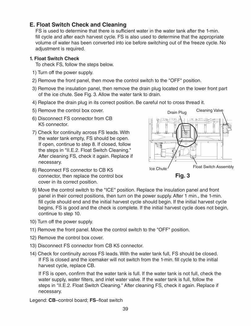
39
E. Float Switch Check and CleaningFS is used to determine that there is sufficient water in the water tank after the 1-min. fill cycle and after each harvest cycle. FS is also used to determine that the appropriate volume of water has been converted into ice before switching out of the freeze cycle. No adjustment is required.
1. Float Switch CheckTo check FS, follow the steps below.
1) Turn off the power supply.
2) Remove the front panel, then move the control switch to the "OFF" position.
3) Remove the insulation panel, then remove the drain plug located on the lower front part of the ice chute. See Fig. 3. Allow the water tank to drain.
4) Replace the drain plug in its correct position. Be careful not to cross thread it.
5) Remove the control box cover.
6) Disconnect FS connector from CB K5 connector.
7) Check for continuity across FS leads. With the water tank empty, FS should be open. If open, continue to step 8. If closed, follow the steps in "II.E.2. Float Switch Cleaning." After cleaning FS, check it again. Replace if necessary.
8) Reconnect FS connector to CB K5 connector, then replace the control box cover in its correct position.
9) Move the control switch to the "ICE" position. Replace the insulation panel and front panel in their correct positions, then turn on the power supply. After 1 min., the 1-min. fill cycle should end and the initial harvest cycle should begin. If the initial harvest cycle begins, FS is good and the check is complete. If the initial harvest cycle does not begin, continue to step 10.
10) Turn off the power supply.
11) Remove the front panel. Move the control switch to the "OFF" position.
12) Remove the control box cover.
13) Disconnect FS connector from CB K5 connector.
14) Check for continuity across FS leads. With the water tank full, FS should be closed. If FS is closed and the icemaker will not switch from the 1-min. fill cycle to the initial harvest cycle, replace CB.
If FS is open, confirm that the water tank is full. If the water tank is not full, check the water supply, water filters, and inlet water valve. If the water tank is full, follow the steps in "II.E.2. Float Switch Cleaning." After cleaning FS, check it again. Replace if necessary.
Legend: CB–control board; FS–float switch
Fig. 3
Drain Plug
Ice Chute Float Switch Assembly
Cleaning Valve

40
2. Float Switch CleaningDepending on local water conditions, scale may build up on FS. Scale on the switch can cause the float to stick. In this case, FS should be cleaned.
1) Turn off the power supply.
2) Remove the front panel, then move the control switch to the "OFF" position.
3) Remove the insulation panel, then remove the drain plug located on the lower front part of the ice chute. See Fig. 3. Allow the water tank to drain.
4) Replace the drain plug in its correct position. Be careful not to cross thread it.
5) Disconnect the vent tube and the flush tube from the top of FS, then remove FS assembly and remove the rubber boot from the bottom of FS assembly. See Fig. 4.
6) Remove the retainer rod from the bottom of FS housing, then remove the float. Be careful not to bend the retainer rod excessively when removing it.
7) Wipe down FS housing, shaft, float, and retainer rod with a mixture of 1 part Hoshizaki "Scale Away" and 25 parts warm water. Clean the inside of the rubber boot and hose with cleaning solution. Rinse the parts thoroughly with clean water.
8) Reassemble FS assembly and replace it and the rubber boot in their correct positions. Reconnect the vent tube and the flush tube.
9) Move the control switch to the "ICE" position.
10) Replace the insulation panel and front panel in their correct positions.
11) Turn on the power supply to start the automatic icemaking process.
Legend: CB–control board; FS–float switch
Float
Float Switch Housing
Rubber Boot and Hose
Retainer Rod
Flush
Vent
Shaft
Fig. 4

41
F. Thermistor CheckTo check thermistor resistance, follow the steps below.
1) Turn off the power supply.
2) Remove the front panel. Move the control switch to the "OFF" position.
3) Remove the control box cover.
4) Remove the thermistor from the refrigerant tubing.
5) Immerse the thermistor sensor portion in a glass containing ice and water for 2 or 3 min.
6) Disconnect the thermistor connector from CB K3 connector and check the resistance between thermistor leads. Normal range is 4.7 to 6.2 kΩ. If outside the normal range, replace the thermistor. See "IV.B. Component Service Information." If within the normal range, continue to the next step.
7) Replace the thermistor in its correct position. See "IV.B. Component Service Information."
8) Reconnect the thermistor connector to CB K3 connector.
9) Replace the control box cover in its correct position.
10) Move the control switch to the "ICE" position.
11) Replace the front panel in its correct position.
12) Turn on the power supply.
13) Once the harvest cycle starts (Comp energizes), begin timing the harvest cycle.
14) The harvest timer and harvest cycle should terminate within 2 to 5 min. If the harvest cycle does not terminate within 2 to 5 min., replace CB.
Legend: CB–control board; Comp–compressor
Foam Insulation Thermistor Holder
Thermistor Lead Cable Tie
Fig. 5

42
G. Diagnostic Tables
1. No Ice Production
No Ice Production - Possible Cause
1. Power Supply a) Off, blown fuse, or tripped breaker.
b) Not within specifications.
2. Main Transformer (KM-1301S_H auxiliary code D-1 and later and all 3 phase models)
a) Voltage tap switch not set to proper voltage.
b) Coil winding open or shorted.
3. Fuse (Control Box) a) Blown.
4. Thermostatic Bin Control See "II.D. Bin Control Check"
a) Tripped with bin filled with ice.
b) Ambient temperature too cool.
c) Set too warm.
d) Bulb out of position.
e) Open contacts, defective.
5. Control Switch a) In "OFF" or "WASH" position.
b) Bad contacts.
6. High-Pressure Switch a) Dirty condenser.
b) Fan motor not operating.
c) Refrigerant overcharged.
d) Bad contacts.
e) Refrigerant lines or components plugged.
7. Control Transformer (115VAC/10.5VAC)
a) Coil winding open or shorted.
8. Control BoardSee "II.C. Control Board Check"
a) In alarm.
b) Yellow "BC OPEN" LED on (bin full) ("G" control board).
c) Defective.
9. Mechanical Bin ControlSee "II.D. Bin Control Check."
a) Tripped with bin filled with ice.
b) Actuator does not move freely.
c) Defective.
10. Water Supply a) Water supply off or improper water pressure.
b) External water filters clogged.
11. Inlet Water Valve a) Screen or orifice clogged.
b) Coil winding open.
c) Water valve open in freeze cycle.
12. Float SwitchSee "II.E. Float Switch Check and Cleaning"
a) Float does not move freely.
b) Defective.
13. Compressor a) Compressor relay/magnetic contactor contacts bad or coil winding open.
b) Start capacitor or run capacitor defective (single phase model).
c) Internal protector open.
d) Start relay contacts bad or coil winding open (single phase model).
e) Compressor defective.
14. Hot Gas Valve a) Closed in harvest cycle.
b) Open in freeze cycle.

43
No Ice Production - Possible Cause
15. ThermistorSee "II.F. Thermistor Check"
a) Loose, disconnected, or defective.
16. Pump Motor a) Motor winding open.
b) Bearing worn out or locked rotor.
c) Defective capacitor.
d) Mechanical seal worn out.
17. Thermostatic Expansion Valve a) Bulb loose.
b) Operating erratically.
18. Liquid Line Valve a) Closed in freeze cycle.
b) Open in harvest cycle.
19. Fan Motor a) Motor winding open.
b) Bearing worn out or locked rotor.
c) Defective capacitor.
20. Water System a) Water leaks causing short freeze time.
2. Freeze-UpDefrost and clean the icemaker prior to diagnosing freeze-up. Fill out a freeze-up checklist. See the Hoshizaki America Technician's Pocket Guide or contact your local distributor for a copy of the freeze-up checklist.
Freeze-Up - Possible Cause
Harvest Cycle
1. Evaporator a) Scaled up.
b) Damaged.
2. Cube Guides a) Out of position.
b) Damaged.
3. Spray Tubes and/or Spray Guides
a) Dirty.
b) Out of position.
4. Water Supply a) Low water pressure.
b) External water filters clogged.
c) Insufficient water line size.Minimum 3/8" Nominal ID (10 mm Nominal OD in the EU) copper water tubing or equivalent.
5. Inlet Water Valve a) Screen or orifice clogged.
b) Defective.
6. Float SwitchSee "II.E. Float Switch Check and Cleaning"
a) Dirty, sticking.
b) Defective.
7. Refrigerant Charge a) Low.
8. Control BoardSee "II.C. Control Board Check" and "III.C. Settings and Adjustments"
a) Harvest timer (S4 dip switch 1 & 2) set too short.
b) Harvest pump timer (S4 dip switch 7) not in factory default position ("G" control board).
c) Defective.
9. Bin ControlSee "II.D. Bin Control Check"
a) Thermostatic: Thermostat bulb loose or defective.
b) Mechanical: Actuator does not move or defective.

44
Freeze-Up - Possible Cause
10. ThermistorSee "II.F. Thermistor Check"
a) Loose, disconnected, or defective.
11. Thermostatic Expansion Valve a) Defective.
12. Hot Gas Valve a) Closed or restricted.
13. Liquid Line Valve a) Open.
Freeze Cycle
1. Evaporator a) Scaled up.
b) Damaged.
2. Spray Tubes and/or Spray Guides
a) Dirty.
b) Out of position.
3. Refrigerant Charge a) Low.
4. Control BoardSee "II.C. Control Board Check"
a) Freeze timer (S4 dip switch 9 & 10) set incorrectly.
b) Defective.
5. Inlet Water Valve a) Leaking by.
6. Float SwitchSee "II.E. Float Switch Check and Cleaning"
a) Float does not move freely.
b) Defective.
7. Pump Motor a) RPM too slow.
b) Impeller damaged.
8. Thermostatic Expansion Valve a) Bulb loose or defective.
9. Liquid Line Valve a) Restricted.
10. Headmaster (C.P.R.) (remote models)
a) Not bypassing.
3. Low Ice Production
Low Ice Production - Possible Cause
Long Harvest Cycle
1. Evaporator a) Scaled up.
2. Spray Tubes and/or Spray Guides
a) Dirty.
b) Out of position.
3. Refrigerant Charge a) Low.
4. Water Supply a) Low water pressure.
b) External water filters clogged.
c) Insufficient water line size.Minimum 3/8" Nominal ID (10 mm Nominal OD in the EU) water tubing or equivalent.
d) Too cold.
5. Control BoardSee "II.C. Control Board Check"
a) Thermistor connection loose (K3).
b) Defective.
6. ThermistorSee "II.F. Thermistor Check"
a) Loose, disconnected, or defective.
7. Hot Gas Valve a) Erratic or closed.
8. Inlet Water Valve a) Screen or orifice clogged.

45
Low Ice Production - Possible Cause
9. Compressor a) Inefficient or off.
10. Liquid Line Valve a) Erratic or open.
11. Thermostatic Expansion Valve a) Defective.
Long Freeze Cycle
1. Evaporator a) Scaled up, dirty.
2. Float SwitchSee "II.E. Float Switch Check and Cleaning"
a) Scaled up, dirty.
b) Float sticking.
c) Defective switch.
3. Inlet Water Valve a) Leaking by.
4. Hot Gas Valve a) Erratic or open.
5. Condenser a) Clogged.
6. Control BoardSee "II.C. Control Board Check"
a) Float switch connection loose (K5).
b) Defective.
7. Refrigerant Charge a) Low.
8. Thermostatic Expansion Valve a) Bulb loose.
b) Defective.
9. Compressor a) Inefficient or off.
10. Pump Motor a) RPM too slow.
11. Liquid Line Valve a) Erratic or restricted.
12. Headmaster (C.P.R.) (remote models)
a) Not bypassing.

46
III. Controls and Adjustments• A Hoshizaki exclusive control board is employed in KM and KMH series appliances.
• All models are pretested and factory adjusted.
• For a control board check procedure, see "II.C. Control Board Check."
NOTICE• Fragile, handle very carefully.
• The control board contains integrated circuits, which are susceptible to failure due to static discharge. It is especially important to touch the metal part of the icemaker when handling or replacing the control board.
• Do not touch the electronic devices on the control board or the back of the control board.
• Do not change wiring and connections. Do not misconnect K3 WHITE, K4 RED, and K5 BLACK, because the same connector is used for the thermistor, mechanical bin control, and float switch. K4 RED is not used on "E" control board models.
• Do not short out power supply to test for voltage.
• Always replace the whole control board assembly if it goes bad.

47
A. Control Board Layout
1. "E" Control Board
"E" Control BoardPart Number 2A1410-02
"E" Control Board
Microprocessor(control board revision level indicated on label on side of relay)
• Part Number
• K1 Connector
Pins #1 through #10#1, 9 Magnetic Contactor or Compressor Relay#2 Hot Gas Valve#3 Fan Motor Liquid Line Valve #4 Pump Motor (icemaking)#5 Pump Motor (pump-out)#6 Inlet Water Valve#7, 10 Component Power Supply #8 Open
Switch for "C" control board and "ALPINE" control board(service control board only)Set to "ALP" for appliances covered in this manual.
• Freeze Timer LED (yellow)
• Harvest Backup Timer LED (orange)
• K2 Connector Control Transformer (10.5VAC)
• "ALARM RESET" Button • S4 Dip Switch• "OUTPUT TEST" Button
(used to test relays on control board)
• K3 (white) ConnectorThermistor(harvest control and high temperature safety)
• K4 (red) Connector Open
• K5 (black) ConnectorFloat Switch(water level)
• LED 1 (X1 Relay)K1 Connector Pin #1, #9
• LED 4 (X4 Relay) K1 Connector Pin #6
• LED 3 (X3 Relay) LED 3 on: K1 Connector Pin #5 LED 3 off: K1 Connector Pin #4 (energized in freeze)
• LED 2 (X2 Relay)LED 2 on: K1 Connector Pin #2LED 2 off: K1 Connector Pin #3
• Relay LEDs (4) (indicate which relays are energized and which K1 connector pins are energized
• POWER OK LED (red) (lights when 10.5VAC is supplied to K2 connector)
• Alarm Buzzer
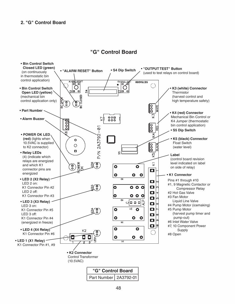
48
2. "G" Control Board
"G" Control BoardPart Number 2A3792-01
"G" Control Board
• K4 (red) Connector Mechanical Bin Control or K4 Jumper (thermostatic bin control application)
Label(control board revision level indicated on label on side of relay)
• K1 Connector
Pins #1 through #10 #1, 9 Magnetic Contactor or Compressor Relay #2 Hot Gas Valve #3 Fan Motor Liquid Line Valve #4 Pump Motor (icemaking) #5 Pump Motor (harvest pump timer and pump-out) #6 Inlet Water Valve #7, 10 Component Power Supply #8 Open
• Bin Control Switch Open LED (yellow)
(mechanical bin control application only)
• Bin Control Switch Closed LED (green)
(on continuously in thermostatic bin control application)
• LED 2 (X2 Relay)LED 2 on: K1 Connector Pin #2LED 2 off: K1 Connector Pin #3
• LED 3 (X3 Relay) LED 3 on: K1 Connector Pin #5 LED 3 off: K1 Connector Pin #4 (energized in freeze)
• LED 4 (X4 Relay) K1 Connector Pin #6
• LED 1 (X1 Relay)K1 Connector Pin #1, #9
• K2 Connector Control Transformer (10.5VAC)
• S5 Dip Switch
• "ALARM RESET" Button • S4 Dip Switch • "OUTPUT TEST" Button(used to test relays on control board)
• K3 (white) ConnectorThermistor (harvest control and high temperature safety)
• K5 (black) ConnectorFloat Switch(water level)
• Part Number
• Alarm Buzzer
• Relay LEDs (4) (indicate which relays are energized and which K1 connector pins are energized
• POWER OK LED (red) (lights when 10.5VAC is supplied to K2 connector)

49
B. LED Lights and Audible Alarm Safeties
1. "E" Control Board
At startup, a 5-second delay occurs while the control board conducts an internal timer check. A beep occurs when power is turned off. The red "POWER OK" LED indicates proper control voltage and remains on unless a control voltage problem occurs. The green LEDs 1 through 4 energize and sequence from initial startup as listed in the table below. Note that the order of the LEDs from the outer edge of the control board is 1, 4, 3, 2.
Sequence Step LEDEnergized
ComponentsTime LEDs are On
Min. Max. Avg.1-Minute Fill Cycle 4 WV 1 minuteHarvest Cycle 1, 4, 2 Comp, FMR, HGV, WV 2 minutes 20 minutes 3 to 5 minutesFreeze Cycle 1 Comp, FM/FMR, PM,
LLV5 minutes freeze timer
setting30 to 35 minutes
Pump-Out Cycle 1, 4*, 3, 2 Comp, FMR, HGV, PM, WV*
10 seconds 20 seconds *pump-out timer setting
The built in safeties shut down the icemaker and have alarms as listed below.
No. of Beeps (every 3 sec.)
Type of Alarm Notes
1 High Evaporator Temp. (temperature > 127°F) (53°C)
Check for harvest problem (stuck HGV or relay), hot water entering icemaker, or shorted thermistor.
2 Harvest Backup Timer (harvest > 20 min. for two cycles in a row)
Orange "H TIMER" LED on. Check for open thermistor, HGV not opening, TXV or LLV leaking by, low charge, or inefficient Comp, or WRV leaking by.
3 Freeze Timer (freeze > specified setting for two cycles in a row)
Yellow "F TIMER" LED on. Check for FS stuck closed (up), WV leaking by, HGV leaking by, PM not pumping, TXV not feeding properly, LLV not opening, low charge, HM not bypassing, or inefficient Comp.
To reset the above safeties, press the "ALARM RESET" button with the power supply on.6 Low Voltage
(92Vac±5% or less)Red LED turns off if voltage protection operates. The control voltage safeties automatically reset when voltage is corrected.7 High Voltage
(147Vac±5% or more)
Legend: Comp–compressor; FM–fan motor; FMR–fan motor remote; FS–float switch; HGV–hot gas valve; HM–headmaster (C.P.R.); LLV–liquid line valve; PM–pump motor; TXV–thermostatic expansion valve; WRV–water regulating valve; WV–inlet water valve

50
2. "G" Control Board
At startup, a 5-second delay occurs while the control board conducts an internal timer check. A beep occurs when the control switch is moved to the "ICE" position. The red "POWER OK" LED indicates proper control voltage and remains on unless a control voltage problem occurs. The green LEDs 1 through 4 energize and sequence from initial startup as listed in the table below. Note that the order of the LEDs from the outer edge of the control board is 1, 4, 3, 2.
Sequence Step LEDEnergized
ComponentsTime LEDs are On
Min. Max. Avg.1-Minute Fill Cycle 4 WV 1 minuteHarvest Cycle 1, 4, 2 Comp, FMR, HGV, WV 2 minutes 20 minutes 3 to 5 minutesHarvest Pump Timer 1, 3, 2 Comp, FMR, HGV, PM 0 seconds 50 seconds harvest pump timer
settingFreeze Cycle 1 Comp, FM/FMR, PM,
LLV5 minutes freeze timer
setting30 to 35 minutes
Pump-Out Cycle 1, 4*, 3, 2 Comp, FMR, HGV, PM, WV*
10 seconds 20 seconds *pump-out timer setting
The built-in safeties shut down the icemaker and have alarms as listed below.
No. of Beeps (every 3 sec.)
Type of Alarm Notes
1 High Evaporator Temp. (temperature > 127°F) (53°C)
Check for harvest problem (stuck HGV or relay), hot water entering icemaker, or shorted thermistor.
2 Harvest Backup Timer (harvest > 20 min. for two cycles in a row)
Check for open thermistor, HGV not opening, TXV or LLV leaking by, low charge, or inefficient Comp, or WRV leaking by.
3 Freeze Timer (freeze > freeze timer setting for two cycles in a row)
Check for FS stuck closed (up), WV leaking by, HGV leaking by, PM not pumping, TXV not feeding properly, LLV not opening, low charge, HM not bypassing, or inefficient Comp.
To reset the above safeties, press the "ALARM RESET" button with the power supply on.6 Low Voltage
(92Vac±5% or less)Red LED turns off if voltage protection operates. The control voltage safeties automatically reset when voltage is corrected.7 High Voltage
(147Vac±5% or more)
Legend: Comp–compressor; FM–fan motor; FMR–fan motor remote; FS–float switch; HGV–hot gas valve; HM–headmaster (C.P.R.); LLV–liquid line valve; PM–pump motor; TXV–thermostatic expansion valve; WRV–water regulating valve; WV–inlet water valve
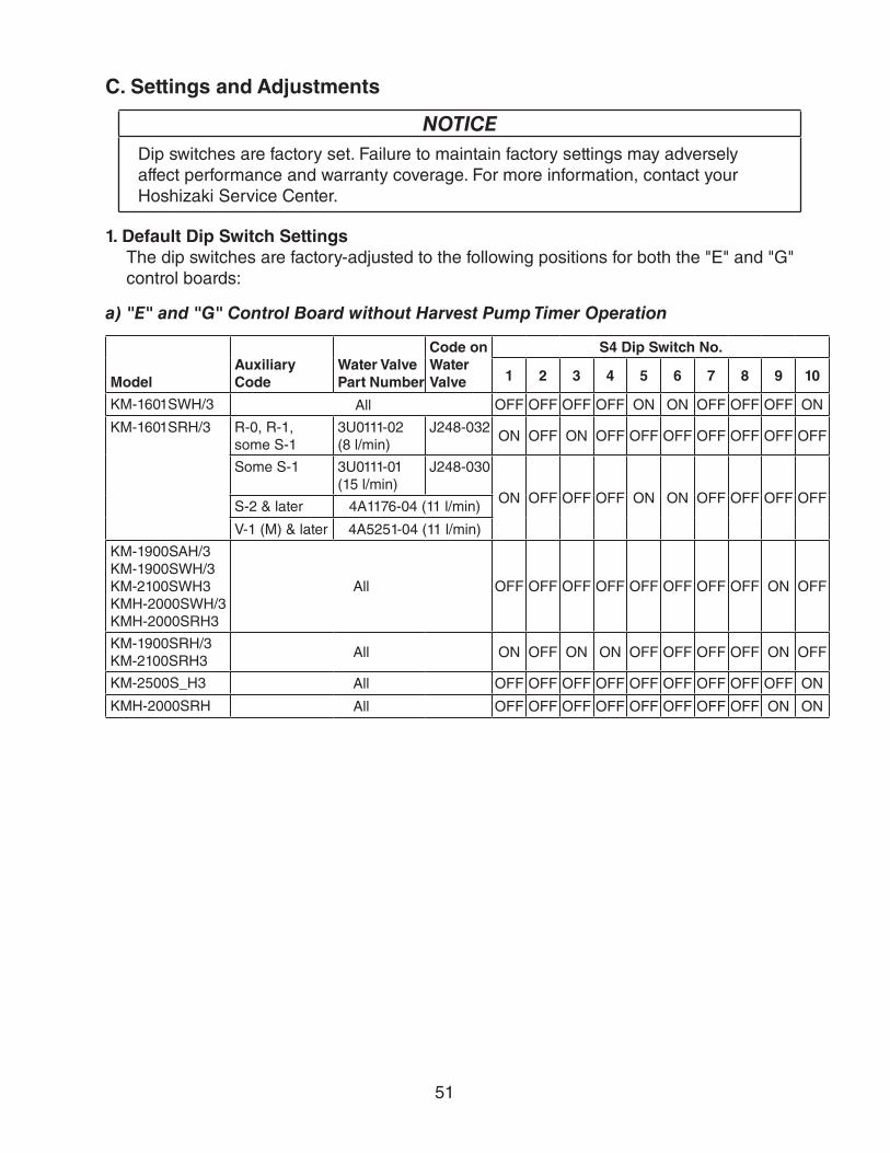
51
C. Settings and Adjustments
NOTICEDip switches are factory set. Failure to maintain factory settings may adversely affect performance and warranty coverage. For more information, contact your Hoshizaki Service Center.
1. Default Dip Switch SettingsThe dip switches are factory-adjusted to the following positions for both the "E" and "G" control boards:
a) "E" and "G" Control Board without Harvest Pump Timer Operation
ModelAuxiliary Code
Water Valve Part Number
Code on Water Valve
S4 Dip Switch No.
1 2 3 4 5 6 7 8 9 10
KM-1601SWH/3 All OFF OFF OFF OFF ON ON OFF OFF OFF ON
KM-1601SRH/3 R-0, R-1, some S-1
3U0111-02(8 l/min)
J248-032ON OFF ON OFF OFF OFF OFF OFF OFF OFF
Some S-1 3U0111-01(15 l/min)
J248-030
ON OFF OFF OFF ON ON OFF OFF OFF OFFS-2 & later 4A1176-04 (11 l/min)
V-1 (M) & later 4A5251-04 (11 l/min)
KM-1900SAH/3 KM-1900SWH/3KM-2100SWH3 KMH-2000SWH/3 KMH-2000SRH3
All OFF OFF OFF OFF OFF OFF OFF OFF ON OFF
KM-1900SRH/3 KM-2100SRH3
All ON OFF ON ON OFF OFF OFF OFF ON OFF
KM-2500S_H3 All OFF OFF OFF OFF OFF OFF OFF OFF OFF ON
KMH-2000SRH All OFF OFF OFF OFF OFF OFF OFF OFF ON ON

52
Freeze Timer (9 & 10)
Pump-Out Frequency Control (5 & 6)
Pump-Out Timer (3 & 4)
Harvest Timer (1 & 2)
Factory Use (8)
Bin Control Selector (7) "E" Control BoardHarvest Pump Timer (7) "G" Control Board(Do Not Adjust)
12
34
56
78
910
ON
S4 Dip Switch "E" and "G" Control Boards
12
34
5
ON Float Switch Selector (1)
Refill Counter (2 through 5)
S5 Dip Switch"G" Control Board
b) "G" Control Board with Harvest Pump Timer Operation
S4 Dip Switch
S4 Dip Switch No. 1 2 3 4 5 6 7 8 9 10
KM-1301SAH/3 KM-1301SWH/3KM-1601SAH/3
OFF OFF ON ON ON ON ON OFF OFF OFF
KM-1301SRH/3 OFF OFF ON ON ON ON ON OFF ON OFF
KM-1400SWH-M KM-1400SWH3-M
OFF OFF OFF OFF OFF OFF ON OFF OFF OFF
c) "G" Control Board S5 Dip Switch
S5 Dip Switch (Do Not Adjust)
S5 Dip Switch No. 1 2 3 4 5
All OFF OFF OFF OFF OFF
2. Harvest Timer (S4 dip switch 1 & 2)The harvest timer starts counting when the thermistor reaches 48°F (9°C) at the evaporator outlet and the control board reads 3.9 kΩ from the thermistor. The harvest timer is factory set, and generally no adjustment is required. However, a setting longer than the factory setting may be advised in cases where the drain provided at harvest needs to be prolonged for extra cleaning. Note that the pump-out timer (S4 dip switch 3 & 4) acts in place of the harvest timer during cycles with a pump out. For details, see "III.C.3. Pump-Out Timer (S4 dip switch 3 & 4)."
Note: On models with a pump-out every cycle, the harvest timer is only relevant during the initial harvest cycle since a pump out occurs every cycle thereafter.
S4 Dip Switch Setting Time (sec.)No. 1 No. 2
OFF OFF 60
ON OFF 90
OFF ON 120
ON ON 180
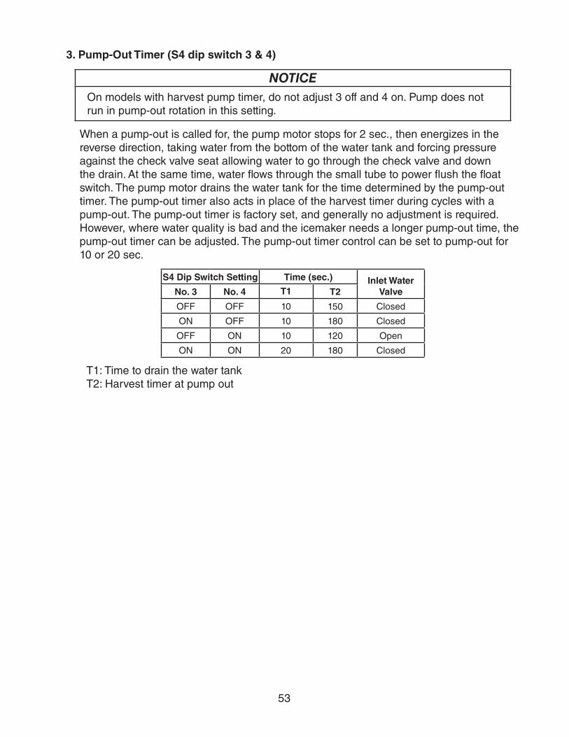
53
3. Pump-Out Timer (S4 dip switch 3 & 4)
NOTICEOn models with harvest pump timer, do not adjust 3 off and 4 on. Pump does not run in pump-out rotation in this setting.
When a pump-out is called for, the pump motor stops for 2 sec., then energizes in the reverse direction, taking water from the bottom of the water tank and forcing pressure against the check valve seat allowing water to go through the check valve and down the drain. At the same time, water flows through the small tube to power flush the float switch. The pump motor drains the water tank for the time determined by the pump-out timer. The pump-out timer also acts in place of the harvest timer during cycles with a pump-out. The pump-out timer is factory set, and generally no adjustment is required. However, where water quality is bad and the icemaker needs a longer pump-out time, the pump-out timer can be adjusted. The pump-out timer control can be set to pump-out for 10 or 20 sec.
S4 Dip Switch Setting Time (sec.) Inlet Water ValveNo. 3 No. 4 T1 T2
OFF OFF 10 150 Closed
ON OFF 10 180 Closed
OFF ON 10 120 Open
ON ON 20 180 Closed
T1: Time to drain the water tankT2: Harvest timer at pump out
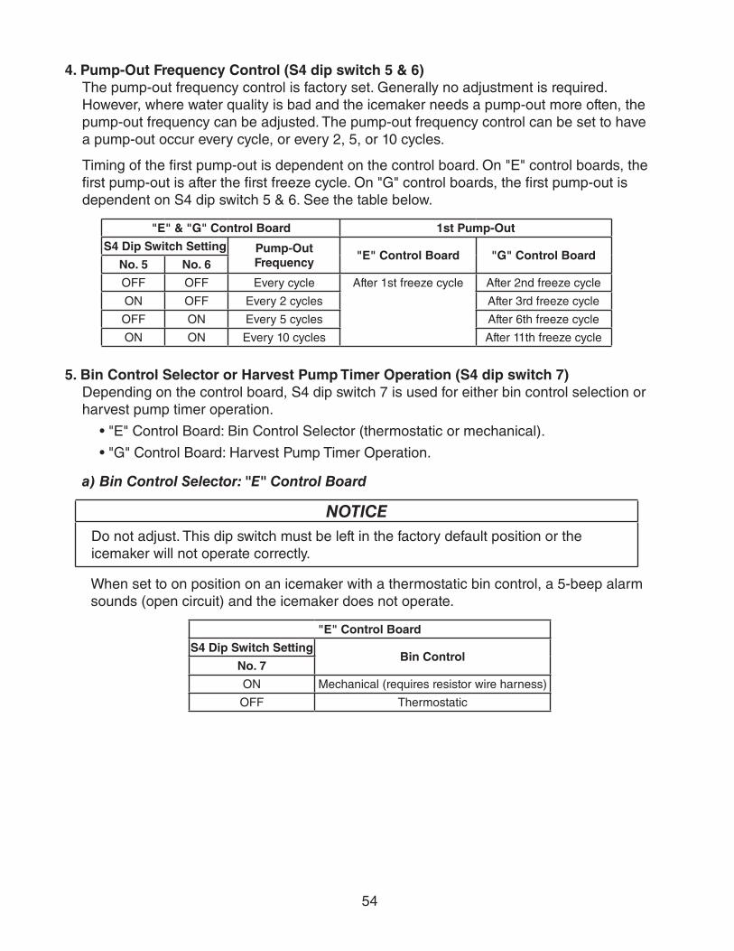
54
4. Pump-Out Frequency Control (S4 dip switch 5 & 6)The pump-out frequency control is factory set. Generally no adjustment is required. However, where water quality is bad and the icemaker needs a pump-out more often, the pump-out frequency can be adjusted. The pump-out frequency control can be set to have a pump-out occur every cycle, or every 2, 5, or 10 cycles.
Timing of the first pump-out is dependent on the control board. On "E" control boards, the first pump-out is after the first freeze cycle. On "G" control boards, the first pump-out is dependent on S4 dip switch 5 & 6. See the table below.
"E" & "G" Control Board 1st Pump-Out
S4 Dip Switch Setting Pump-Out Frequency
"E" Control Board "G" Control BoardNo. 5 No. 6
OFF OFF Every cycle After 1st freeze cycle After 2nd freeze cycle
ON OFF Every 2 cycles After 3rd freeze cycle
OFF ON Every 5 cycles After 6th freeze cycle
ON ON Every 10 cycles After 11th freeze cycle
5. Bin Control Selector or Harvest Pump Timer Operation (S4 dip switch 7)Depending on the control board, S4 dip switch 7 is used for either bin control selection or harvest pump timer operation.
• "E" Control Board: Bin Control Selector (thermostatic or mechanical).
• "G" Control Board: Harvest Pump Timer Operation.
a) Bin Control Selector: "E" Control Board
NOTICEDo not adjust. This dip switch must be left in the factory default position or the icemaker will not operate correctly.
When set to on position on an icemaker with a thermostatic bin control, a 5-beep alarm sounds (open circuit) and the icemaker does not operate.
"E" Control Board
S4 Dip Switch SettingBin Control
No. 7
ON Mechanical (requires resistor wire harness)
OFF Thermostatic

55
b) Harvest Pump Timer: "G" Control Board
NOTICEFactory set for proper operation. Do not adjust. Adjustment outside of the factory default setting may result in damage to the appliance.
Depending on the harvest pump timer setting, the pump motor either stays off or is energized the last 50 seconds of harvest. When the pump motor is energized, water circulates over the evaporator. The harvest water valve is open during harvest for a maximum of 6 minutes or the length of harvest minus 0 or 50 seconds (determined by the harvest pump timer setting), whichever is shorter. When S4 dip switch 7 is in the on position and harvest begins, X11 and X10 relays energize. A latching circuit is created through the X11 and X10 relays. For further details, see "VIII.C. Wiring Diagrams." 50 sec. before harvest termination, LED 4 turns off, inlet water valve and X11 relay de-energize. X10 relay remains energized through the latching circuit. Next, LED 3 turns on and control board K1 connector pin #5 (DBU wire) energizes, energizing the pump motor for the last 50 sec. of harvest.
"G" Control Board
S4 Dip Switch Setting Pump Motor Time (sec.)No. 7
ON 50
OFF 0
6. Factory Use (S4 dip switch 8)Factory set for proper operation. Do not adjust. This must be left in the factory default position.
7. Freeze Timer (S4 dip switch 9 & 10)
NOTICEAdjust to proper specification, or the icemaker may not operate correctly.
The freeze timer setting determines the maximum allowed freeze time to prevent possible freeze-up issues. Upon termination of the freeze timer, the control board initiates the harvest cycle or pump-out cycle. After 2 consecutive freeze timer terminations, the control board shuts down the icemaker. In this case, see "II.G.3. Low Ice Production" for possible solutions. The freeze timer is factory set and no adjustment is required. Before changing this setting, contact Hoshizaki Technical Support at 1-800-233-1940 for recommendations.
S4 Dip Switch Setting Time (min.)No. 9 No. 10
OFF OFF 60
OFF ON 50
ON OFF 70
ON ON 75
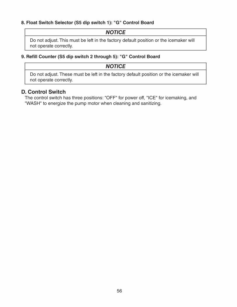
56
8. Float Switch Selector (S5 dip switch 1): "G" Control Board
NOTICEDo not adjust. This must be left in the factory default position or the icemaker will not operate correctly.
9. Refill Counter (S5 dip switch 2 through 5): "G" Control Board
NOTICEDo not adjust. These must be left in the factory default position or the icemaker will not operate correctly.
D. Control SwitchThe control switch has three positions: "OFF" for power off, "ICE" for icemaking, and"WASH" to energize the pump motor when cleaning and sanitizing.

57
IV. Refrigeration Circuit and Component Service Information
WARNING• This appliance should be diagnosed and repaired only by qualified service
personnel to reduce the risk of death, electric shock, serious injury, or fire.
• Move the control switch to the "OFF" position and turn off the power supply. Place the disconnect in the "OFF" position. Lockout/Tagout to prevent the power supply from being turned back on inadvertently.
• CHOKING HAZARD: Ensure all components, fasteners, and thumbscrews are securely in place after the icemaker is serviced. Make sure that none have fallen into the dispenser unit/ice storage bin.
• Make sure all food zones in the icemaker and dispenser unit/ice storage bin are clean after service.
A. Refrigeration Circuit Service Information
WARNING• Repairs requiring the refrigeration circuit to be opened must be performed by
properly trained and EPA-certified service personnel.
• Use an electronic leak detector or soap bubbles to check for leaks. Add a trace of refrigerant to the system (if using an electronic leak detector), and then raise the pressure using nitrogen gas (140 PSIG). Do not use R-404A as a mixture with pressurized air for leak testing.
NOTICE• Always recover the refrigerant and store it in an approved container. Do not
discharge the refrigerant into the atmosphere.
• Do not leave the system open for longer than 15 min. when replacing or servicing parts. The Polyol Ester (POE) oils used in R-404A applications can absorb moisture quickly. Therefore it is important to prevent moisture from entering the system when replacing or servicing parts.
• Always install a new drier every time the sealed refrigeration system is opened. Do not replace the drier until after all other repair or replacement has been made. Install the new drier with the arrow on the drier in the direction of the refrigerant flow.
• When brazing, protect the drier by using a wet cloth to prevent the drier from overheating. Do not allow the drier to exceed 250°F (121°C).
1. Refrigerant RecoveryThe icemaker is provided with refrigerant service valves. Using proper refrigerant practices, recover the refrigerant. Store the refrigerant in an approved container. Do not discharge the refrigerant into the atmosphere.

58
2. Brazing
WARNING• R-404A itself is not flammable at atmospheric pressure and temperatures up to
176°F (80°C).
• R-404A itself is not explosive or poisonous. However, when exposed to high temperatures (open flames), R-404A can be decomposed to form hydrofluoric acid and carbonyl fluoride both of which are hazardous.
• Do not use silver alloy or copper alloy containing arsenic.
1) Braze all fittings while purging with nitrogen gas flowing at a pressure of 3 to 4 PSIG.Note: Because the pipes in the evaporator case are specially coated to resist corrosion,
it is important to make connections outside the evaporator case when possible. If it is necessary to braze inside the evaporator case, use sandpaper to remove the coating from the brazing connections before unbrazing the components.
NOTICE• Always install a new drier every time the sealed refrigeration system is opened.
• Do not replace the drier until after all other repair or replacement has been made. Install the new drier with the arrow on the drier in the direction of the refrigerant flow.
• When brazing, protect the drier by using a wet cloth to prevent the drier from overheating. Do not allow the drier to exceed 250°F (121°C).
2) Use an electronic leak detector or soap bubbles to check for leaks. Add a trace of refrigerant to the system (if using an electronic leak detector), and then raise the pressure using nitrogen gas (140 PSIG). Do not use R-404A as a mixture with pressurized air for leak testing.
3. Evacuation and Recharge (R-404A)
1) Attach a vacuum pump to the system. Be sure to connect the charging hoses to both high and low-side refrigerant access valves.
IMPORTANTThe vacuum level and vacuum pump may be the same as those for current refrigerants. However, the rubber hose and gauge manifold to be used for evacuation and refrigerant charge should be exclusively for POE oils.
2) Turn on the vacuum pump. Open the gauge manifold valves, then open the high and low-side service valves. Never allow the oil in the vacuum pump to flow backwards.
3) Allow the vacuum pump to pull down to a 29.9" Hg vacuum. Evacuating period depends on pump capacity.
59
4) Close the low-side valve and high-side valve on the gauge manifold.
5) Disconnect the gauge manifold hose from the vacuum pump and attach it to a refrigerant service cylinder. Remember to loosen the connection and purge the air from the hose. For the required refrigerant charge, see the rating label inside the icemaker. Hoshizaki recommends only virgin refrigerant or reclaimed refrigerant which meets ARI Standard 700 (latest edition) be used.
6) A liquid charge is required when charging an R-404A system (to prevent fractionation). Place the service cylinder on the scales; if the service cylinder is not equipped with a dip tube, invert the service cylinder, then place it on the scales. Open the high-side valve on the gauge manifold.
7) Allow the system to charge with liquid until the proper charge weight is met.
8) If necessary, add any remaining charge to the system through the low-side. NOTICE! To prevent compressor damage, use a throttling valve or liquid dispensing device to add the remaining liquid charge through the low-side refrigerant service valve with the icemaker running.
9) Close the high and low-side service valves, then close the high and low-side gauge manifold valves. Disconnect the gauge manifold hoses.
10) Cap the refrigerant service valves to prevent a possible leak.

60
B. Component Service Information
NOTICEWhen replacing a component listed below, see the notes to help ensure proper operation.
Component Notes
Compressor 1 phase: Install a new start capacitor, run capacitor, and start relay.3 phase: Install a new magnetic contactor.
Thermostatic Expansion Valves
• Attach the thermostatic expansion valve bulb to the suction line in the same location as the previous bulb.
• The bulb should be between the 10 and 2 o'clock positions on the tube.
• Secure the bulb with the clamp and holder, then insulate it.
Hot Gas ValvesLiquid Line Valves
• Replace the strainer if applicable.
• Use copper tube of the same diameter and length when replacing valve lines.
Fan Motors Install a new capacitor.
Pump Motor Install a new capacitor.
Thermistor • Attach the new thermistor to the suction line in the same location as the previous thermistor.
• The thermistor should be at the 12 o'clock position on the tube.
• Smoothly fill the recessed area of the thermistor holder with high thermal conductive type sealant. Hoshizaki America part number 4A0683-01 (Silicone Heat Sink Compound 10-8108 manufactured by GC Electronics), KE-4560 RTV (manufactured by ShinEtsu Silicones), or equivalent are recommended.
• Secure the thermistor with the holder, then insulate it.
• Be very careful to prevent damage to the leads.
KM-1400SWH-M, KM-1400SWH3-M Water Regulating Valve
Tighten the water regulating valve flare nut to a torque of 39.8 ft-lb/53.9 N·m.

61
C. Water Regulating Valve Adjustment (water-cooled models)The water regulating valve is factory set, and generally no adjustment is required. However, when necessary, adjust the water regulator using the following procedure.
1) Prepare a thermometer to check the condenser drain temperature. Attach a pressure gauge to the high-side line of the system.
2) 5 min. after a freeze cycle starts, confirm that the thermometer reads 104°F to 115°F (40°C to 46°C). If it does not, rotate the adjustment screw by using a flat blade screwdriver until the temperature is in the proper range (rotate counterclockwise to raise temperature or clockwise to lower temperature). See Fig. 6. Next, check that the reference pressure is in the range indicated in "VIII.A. Specification and Performance Data." If it is not in the proper range, verify the refrigerant charge.
3) Check that the condenser drain temperature is stable.
Fig. 6
Adjustment Screw
CW – LowerCCW – Higher
Top View

62
V. Maintenance
The maintenance schedule below is a guideline. More frequent maintenance may berequired depending on water quality, the appliance's environment, and local sanitationregulations
WARNING• Only qualified service technicians should service the appliance.
• To reduce the risk of electric shock, do not touch the control switch or service switch with damp hands
• Before servicing: Move the control switch to the "OFF" position and turn off the power supply. Place the disconnect in the "OFF" position. Lockout/Tagout to prevent the power supply from being turned back on inadvertently.
• CHOKING HAZARD: Ensure all components, fasteners, and thumbscrews are securely in place after any maintenance is done to the icemaker. Make sure that none have fallen into the dispenser unit/ice storage bin.
Maintenance ScheduleFrequency Area Task
Daily Scoop Clean the ice scoop using a neutral cleaner. Rinse thoroughly after cleaning.
Bi-Weekly Air Filters Inspect. Wash with warm water and neutral cleaner if dirty.
Monthly External Water Filters
Check for proper pressure and change if necessary.
Icemaker Exterior Wipe down with a clean, soft cloth. Use a damp cloth containing a neutral cleaner to wipe off oil or dirt build up. Clean any chlorine staining (rust colored spots) using a non-abrasive cleanser.
Yearly Icemaker and Dispenser Unit/Ice Storage Bin Liner
Clean and sanitize per the cleaning and sanitizing instructions provided in the instruction manual or maintenance label on the icemaker.
Water Supply Inlet Close the icemaker water supply line shut-off valve and drain the water system. Clean the water supply inlet screen.
Condenser Inspect. Clean if necessary by using a brush or vacuum cleaner. More frequent cleaning may be required depending on location.
Water Hoses Inspect the water hoses and clean/replace if necessary.
As Needed Marine Model Condenser
If contaminated seawater enters the system, flush with clean seawater or fresh water as soon as possible to minimize damage to the condenser.

63
VI. Preparing the Icemaker for Periods of Non-UseNOTICE
• When storing the appliance for an extended time or in sub-freezing temperatures, follow the instructions below to prevent damage.
• To prevent damage to the water pump, do not operate the appliance with the control switch in the "WASH" position when the water tank is empty.
When the appliance is not used for two or three days under normal conditions, it is sufficient to move the control switch to the "OFF" position. When storing the appliance for an extended time or in sub-freezing temperatures, follow the instructions below.
1. Remove the water from the icemaker water supply line:
1) Turn off the power supply, then remove the front panel.
2) Move the control switch to the "OFF" position.
3) Close the icemaker water supply line shut-off valve, then open the icemaker water supply line drain valve.
4) Allow the line to drain by gravity.
5) Attach a compressed air or carbon dioxide supply to the icemaker water supply line drain valve.
6) Move the control switch to the "ICE" position.
7) Replace the front panel in its correct position, then turn on the power supply.
8) Blow the icemaker water supply line out using the compressed air or carbon dioxide supply.
9) Close the icemaker water supply line drain valve.
2. Drain the water tank:
1) Turn off the power supply, then remove the front panel.
2) Move the control switch to the "OFF" position.
3) Remove the insulation panel. Remove the drain plug located on the lower front part of the ice chute. See Fig. 7. Allow the water tank to drain.
4) Replace the drain plug and the insulation panel in their correct positions. Be careful not to cross thread the drain plug.
5) Remove all ice from the dispenser unit/ice storage bin. Clean the dispenser unit/ice storage bin liner using a neutral cleaner. Rinse thoroughly after cleaning.
6) Replace the front panel in its correct position.
Fig. 7
Drain Plug
Ice Chute Float Switch Assembly
Cleaning Valve
64
3. On water-cooled model, remove the water from the water-cooled condenser:
1) Make sure the power supply is off, then remove the front, top, and right side panels.
2) Close the condenser water supply line shut-off valve. If connected to a closed loop system, also close the condenser return line shut-off valve.
3) Open the condenser water supply line drain valve. If connected to a closed loop system, also open the condenser return line drain valve.
4) Attach a compressed air or carbon dioxide supply to the condenser water supply line drain valve.
5) Open the water regulating valve by using a screwdriver to pry up on the spring retainer underneath the spring. While holding the valve open, blow out the condenser using the compressed air or carbon dioxide supply until water stops coming out.
6) Close the drain valve(s).
7) Replace the right side, top, and front panels in their correct positions.

65
VII. DisposalThe appliance contains refrigerant and must be disposed of in accordance with applicable national, state, and local codes and regulations. Refrigerant must be recovered by properly certified service personnel.

66
VIII. Technical InformationWe reserve the right to make changes in specifications and design without prior notice.
A. Specification and Performance DataPressure data is recorded at 5 min. into freezing cycle. The data not in bold should be used for reference only.
1. KM-1301SAHSPECIFICATION SHEETAC SUPPLY VOLTAGE 208-230/60/1 (3 wire with neutral for 115V) or 208-230/60/1AMPERAGE 12.4 A ( 5 Min. Freeze AT 104°F / WT 80°F)
MINIMUM CIRCUIT AMPACITY 20 AMAXIMUM FUSE SIZE 20 AELECTRIC & WATER CONSUMPTION 90/70°F 70/50°F ELECTRIC W (kWH/100 lbs.) 2250 (4.63) 2160 (3.9) WATER gal./24HR (gal./100 lbs.) 183 (15.7) 605 (45.5)ICE PRODUCTION PER CYCLE 29.8 lbs. (13.5 kg) 1440pcs.REFRIGERANT CHARGE R404A, 3 lb. 15.5 oz. (1800g)
PERFORMANCE DATA
70/21 1329 603 1281 581 1188 53980/27 1292 586 1217 552 1109 50390/32 1281 581 1164 528 1060 481
lbs./day kg./day 100/38 1253 568 1140 517 965 43870/2180/2790/32
watts 100/3870/21 605 2.29 481 1.82 429 1.6280/27 510 1.93 318 1.21 331 1.2590/32 481 1.82 183 0.69 167 0.63
gal./day m3/day 100/38 345 1.30 179 0.68 152 0.5870/2180/2790/32
min. 100/3870/2180/2790/32
min. 100/3870/21 255 17.9 273 19.2 298 20.980/27 269 18.9 297 20.9 321 22.690/32 273 19.2 317 22.3 342 24.0
PSIG kg/cm2G 100/38 278 19.5 323 22.7 365 25.770/21 50 3.5 50 3.5 53 3.880/27 50 3.5 50 3.5 55 3.990/32 50 3.5 50 3.5 55 3.8
PSIG kg/cm2G 100/38 52 3.6 51 3.6 59 4.1
20,300 BTU/h [AT 90ºF (32ºC) / WT 70ºF (21ºC)]
2253
APPROXIMATE ICE PRODUCTION PER 24 HR.
AMBIENT TEMP. (ºF/ºC)
WATER TEMP. (ºF/ºC)50/10 70/21 90/32
34
APPROXIMATE ELECTRIC CONSUMPTION
2160 2166 22222164 2174 22572166 2180
37
2193 2197 2320APPROXIMATE WATER CONSUMPTION PER 24 HR.
FREEZING CYCLE TIME 31 32 353232 35 3833 36 41
3.74.1 2.9 3.13.9 2.1
TOTAL HEAT OF REJECTION FROM CONDENSER
SUCTION PRESSURE
2.13.1 2.1 2.1
HEAD PRESSURE
HARVEST CYCLE TIME 4.7 3.9
ENG.F-011.1.0205
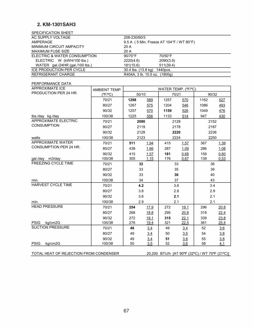
67
2. KM-1301SAH3
SPECIFICATION SHEETAC SUPPLY VOLTAGE 208-230/60/3AMPERAGE 9.5 A ( 5 Min. Freeze AT 104°F / WT 80°F)MINIMUM CIRCUIT AMPACITY 20 AMAXIMUM FUSE SIZE 20 AELECTRIC & WATER CONSUMPTION 90/70°F 70/50°F ELECTRIC W (kWH/100 lbs.) 2220(4.6) 2090(3.9) WATER gal./24HR (gal./100 lbs.) 181(15.6) 511(39.4)ICE PRODUCTION PER CYCLE 30.4 lbs. (13.8 kg) 1440pcs.REFRIGERANT CHARGE R404A, 3 lb. 15.5 oz. (1800g)
PERFORMANCE DATA
70/21 1298 589 1257 570 1162 52780/27 1267 575 1204 546 1086 49390/32 1257 570 1159 526 1049 476
lbs./day kg./day 100/38 1225 556 1133 514 947 43070/2180/2790/32
watts 100/3870/21 511 1.94 415 1.57 367 1.3980/27 438 1.66 287 1.09 286 1.0890/32 415 1.57 181 0.68 159 0.60
gal./day m3/day 100/38 305 1.15 176 0.67 139 0.5370/2180/2790/32
min. 100/3870/2180/2790/32
min. 100/3870/21 254 17.9 272 19.1 296 20.880/27 268 18.8 295 20.8 319 22.490/32 272 19.1 315 22.1 339 23.8
PSIG kg/cm2G 100/38 276 19.4 321 22.5 361 25.470/21 48 3.4 49 3.4 52 3.680/27 49 3.4 50 3.5 54 3.890/32 49 3.4 51 3.6 55 3.8
PSIG kg/cm2G 100/38 50 3.5 52 3.6 58 4.1
20,200 BTU/h [AT 90ºF (32ºC) / WT 70ºF (21ºC)]
3233
373334
36
APPROXIMATE ELECTRIC CONSUMPTION
APPROXIMATE WATER CONSUMPTION PER 24 HR.
FREEZING CYCLE TIME 3335
2.1
4.2
2.9
3.62.8
WATER TEMP. (ºF/ºC)AMBIENT TEMP. (ºF/ºC) 50/10 70/21 90/32
APPROXIMATE ICE PRODUCTION PER 24 HR.
2123
2128217822202224
209021192128
2.1
2152218722362250
36394043
TOTAL HEAT OF REJECTION FROM CONDENSER
SUCTION PRESSURE
HARVEST CYCLE TIME
HEAD PRESSURE
3.42.9
3.6 2.12.13.8
ENG.F-011.1.0205

68
3. KM-1301SWH
SPECIFICATION SHEETAC SUPPLY VOLTAGE 208-230/60/1 (3 wire with neutral for 115V) or 208-230/60/1AMPERAGE 8.2 A ( 5 Min. Freeze AT 104°F / WT 80°F)MINIMUM CIRCUIT AMPACITY 20 AMAXIMUM FUSE SIZE 20 A
90/70°F 70/50°F ELECTRIC W (kWH/100 lbs.) 1760(3.2) 1740(3.2) WATER gal./24HR (gal./100 lbs.) 257(19.4) 546(41.4) WATER COOLED CONDENSER 1561(118) 861(65)gal./24HR (gal./100 lbs.)ICE PRODUCTION PER CYCLE 31 lbs. (14.1 kg) 1440pcs.REFRIGERANT CHARGE R404A, 2 lb. 8.2 oz. (1140g)
PERFORMANCE DATA
70/21 1318 598 1319 599 1249 56780/27 1319 598 1321 599 1211 54990/32 1319 599 1323 600 1228 557
lbs./day kg./day 100/38 1281 581 1301 590 1141 51870/2180/2790/32
watts 100/3870/21 1407 5.33 1527 5.78 2049 7.7680/27 1499 5.67 1686 6.38 2406 9.1190/32 1527 5.78 1818 6.88 2465 9.33
gal./day m3/day 100/38 1861 7.04 1969 7.46 3060 11.5870/2180/2790/32
min. 100/3870/2180/2790/32
min. 100/3870/21 235 16.5 236 16.6 246 17.380/27 236 16.6 237 16.7 253 17.890/32 236 16.6 238 16.7 252 17.7
PSIG kg/cm2G 100/38 241 16.9 241 17.0 264 18.670/21 50 3.5 50 3.5 52 3.680/27 50 3.5 49 3.5 52 3.790/32 50 3.5 49 3.4 52 3.6
PSIG kg/cm2G 100/38 51 3.6 50 3.5 54 3.8
17,600 BTU/h [AT 90ºF (32ºC) / WT 70ºF (21ºC)]TOTAL HEAT OF REJECTION FROM COMPRESSOR 2,300 BTU/h [AT 90ºF (32ºC) / WT 70ºF (21ºC)]WATER FLOW FOR CONDENSER 120 gal./h [AT 100ºF (38ºC) / WT 90ºF (32ºC)]PRESSURE DROP OF COOLING WATER LINE less than 10 PSIG
2.1
TOTAL HEAT OF REJECTION FROM CONDENSER
SUCTION PRESSURE
HEAD PRESSURE
3132
32
HARVEST CYCLE TIME 3.53.0
17601766
3.9 2.22.44.0
33343436
1746
APPROXIMATE ICE PRODUCTION PER 24 HR.
APPROXIMATE ELECTRIC CONSUMPTION
APPROXIMATE WATER CONSUMPTION PER 24 HR.
1767178217861810
17461754
AMBIENTTEMP. (ºF/ºC) 50/10 70/21 90/32
1755
313132
17401744
ELECTRIC & WATER CONSUMPTION
2.4
4.5
3.2
3.93.1
31
33
FREEZING CYCLE TIME
WATER TEMP. (ºF/ºC)
ENG.F-011.1.0205

69
4. KM-1301SWH3
SPECIFICATION SHEET208-230/60/36.1 A ( 5 Min. Freeze AT 104°F / WT 80°F)20 A
20 A90/70°F 70/50°F1840(3.4) 1770(3.2)248(19.1) 557(41.8)1547(119) 857(64)
32.2 lbs. (14.6 kg) 1440pcs.R404A, 2 lb. 8.2 oz. (1140g)
PERFORMANCE DATA
70/21 1333 605 1323 600 1246 56580/27 1326 601 1311 594 1198 54490/32 1323 600 1300 590 1201 545
lbs./day kg./day 100/38 1286 584 1277 579 1110 50370/2180/2790/32
watts 100/38APPROXIMATE WATER 70/21 1414 5.35 1526 5.78 2036 7.71
80/27 1499 5.68 1673 6.33 2382 9.0290/32 1526 5.78 1795 6.80 2431 9.20
gal./day m3/day 100/38 1846 6.99 1944 7.36 3015 11.41FREEZING CYCLE TIME 70/21 30 31 32
80/27 31 32 3390/32 31 32 34
min. 100/38 31 33 35HARVEST CYCLE TIME 70/21 4.5 3.8 3.5
80/27 4.0 3.0 3.090/32 3.8 2.4 2.2
min. 100/38 3.1 2.3 2.1HEAD PRESSURE 70/21 237 16.7 238 16.7 249 17.5
80/27 238 16.7 239 16.8 256 18.090/32 238 16.7 240 16.9 255 17.9
PSIG kg/cm2G 100/38 244 17.1 244 17.1 269 18.9SUCTION PRESSURE 70/21 50 3.5 50 3.5 52 3.7
80/27 50 3.5 49 3.5 53 3.790/32 50 3.5 49 3.4 52 3.7
PSIG kg/cm2G 100/38 51 3.6 50 3.5 55 3.9
TOTAL HEAT OF REJECTION FROM CONDENSER 17,400 BTU/h [AT 90ºF (32ºC) / WT 70ºF (21ºC)]
TOTAL HEAT OF REJECTION FROM COMPRESSOR 2,300 BTU/h [AT 90ºF (32ºC) / WT 70ºF (21ºC)]WATER FLOW FOR CONDENSER 119 gal./h [AT 100ºF (38ºC) / WT 90ºF (32ºC)]PRESSURE DROP OF COOLING WATER LINE less than 10 PSIG
AMBIENT TEMP. (ºF/ºC)
1789 1842 186018401791
1805
90/32
18241850
1770 17911786
ICE PRODUCTION PER CYCLEREFRIGERANT CHARGE
50/10WATER TEMP. (ºF/ºC)
1818APPROXIMATE ELECTRIC CONSUMPTION
70/21APPROXIMATE ICE PRODUCTION PER 24 HR.
AC SUPPLY VOLTAGEAMPERAGEMINIMUM CIRCUIT AMPACITY
MAXIMUM FUSE SIZEELECTRIC & WATER CONSUMPTION ELECTRIC W (kWH/100 lbs.) WATER gal./24HR (gal./100 lbs.) WATER COOLED CONDENSERgal./24HR (gal./100 lbs.)
ENG.F-011.1.0205

70
5. KM-1301SRH with URC-14F
SPECIFICATION SHEETAC SUPPLY VOLTAGE 208-230/60/1 (3 wire with neutral for 115V) or 208-230/60/1AMPERAGE 13.5A ( 5 Min. Freeze AT 104°F / WT 80°F)MINIMUM CIRCUIT AMPACITY 20 AMAXIMUM FUSE SIZE 20 AELECTRIC & WATER CONSUMPTION 90/70°F 70/50°F ELECTRIC W (kWH/100 lbs.) 2090(4.1) 2010(3.6) WATER gal./24HR (gal./100 lbs.) 203(16.6) 479(35.4)ICE PRODUCTION PER CYCLE 31.1 lbs. (14.1 kg) 1440pcs.TOTAL REFRIGERANT CHARGE R404A, 10 lbs. 5.8 oz. (4700g)REFRIGERANT CHARGE BY UNIT (Icemaker 5 lbs. 15.2 oz. Cond. Unit 4 lbs. 6.5 oz.)
PERFORMANCE DATA
70/21 1353 614 1315 596 1219 55380/27 1324 600 1264 573 1144 51990/32 1315 596 1222 554 1110 504
lbs./day kg./day 100/38 1281 581 1196 542 1008 45770/2180/2790/32
watts 100/3870/21 479 1.81 398 1.51 350 1.3280/27 417 1.58 292 1.10 278 1.0590/32 398 1.51 203 0.77 173 0.66
gal./day m3/day 100/38 303 1.15 196 0.74 146 0.5570/2180/2790/32
min. 100/3870/2180/2790/32
min. 100/3870/21 211 14.8 226 15.9 246 17.380/27 222 15.6 246 17.3 265 18.790/32 226 15.9 262 18.4 282 19.9
PSIG kg/cm2G 100/38 230 16.2 267 18.8 301 21.270/21 50 3.5 51 3.6 53 3.880/27 50 3.5 51 3.6 55 3.990/32 51 3.6 52 3.7 56 3.9
PSIG kg/cm2G 100/38 52 3.6 53 3.7 59 4.1
17,600 BTU/h [AT 90ºF (32ºC) / WT 70ºF (21ºC)]2,500 BTU/h [AT 90ºF (32ºC) / WT 70ºF (21ºC)]
CONDENSER VOLUME 133 CU. IN (URC-14F)
3.6 2.2
TOTAL HEAT OF REJECTION FROM CONDENSERTOTAL HEAT OF REJECTION FROM COMPRESSOR
353233
35
2.1
SUCTION PRESSURE
HARVEST CYCLE TIME
HEAD PRESSURE
3.32.9
34363740
20882131215322102052
2033206420902105
201020282033
31
APPROXIMATE ICE PRODUCTION PER 24 HR.
APPROXIMATE ELECTRIC CONSUMPTION
APPROXIMATE WATER CONSUMPTION PER 24 HR.
FREEZING CYCLE TIME
WATER TEMP. (ºF/ºC)AMBIENT TEMP. (ºF/ºC) 50/10 70/21 90/32
323233
2.3
4.1
3.0
3.62.92.3
3.7
ENG.F-011.1.0205

71
6. KM-1301SRH3 with URC-14F
SPECIFICATION SHEETAC SUPPLY VOLTAGE 208-230/60/3AMPERAGE 10.7A ( 5 Min. Freeze AT 104°F / WT 80°F)MINIMUM CIRCUIT AMPACITY 20 AMAXIMUM FUSE SIZE 20 A
90/70°F 70/50°F ELECTRIC W (kWH/100 lbs.) 2140(4.3) 2090(3.8) WATER gal./24HR (gal./100 lbs.) 192(16.0) 463(34.6)ICE PRODUCTION PER CYCLE 30.7 lbs. (13.9 kg) 1440pcs.TOTAL REFRIGERANT CHARGE R404A, 10 lbs. 5.8 oz. (4700g)REFRIGERANT CHARGE BY UNIT (Icemaker 5 lbs. 15.2 oz. Cond. Unit 4 lbs. 6.5 oz.)
PERFORMANCE DATA
70/21 1339 607 1297 589 1203 54680/27 1307 593 1243 564 1127 51190/32 1297 589 1197 543 1088 494
lbs./day kg./day 100/38 1266 574 1171 531 988 44870/2180/2790/32
watts 100/38APPROXIMATE WATER 70/21 463 1.75 384 1.45 338 1.28
80/27 403 1.52 279 1.06 269 1.0290/32 384 1.45 192 0.72 165 0.63
gal./day m3/day 100/38 291 1.10 185 0.70 141 0.53FREEZING CYCLE TIME 70/21 31 32 35
80/27 32 34 3790/32 32 35 39
min. 100/38 33 36 42HARVEST CYCLE TIME 70/21 3.9 3.4 3.2
80/27 3.5 2.8 2.890/32 3.4 2.2 2.1
min. 100/38 2.9 2.2 2.1HEAD PRESSURE 70/21 214 15.0 228 16.0 252 17.7
80/27 224 15.8 246 17.3 273 19.290/32 228 16.0 261 18.4 287 20.2
PSIG kg/cm2G 100/38 234 16.5 267 18.8 311 21.9SUCTION PRESSURE 70/21 50 3.5 51 3.6 54 3.8
80/27 50 3.5 51 3.6 56 3.990/32 51 3.6 52 3.7 56 3.9
PSIG kg/cm2G 100/38 52 3.7 53 3.7 60 4.2
TOTAL HEAT OF REJECTION FROM CONDENSER 17,500 BTU/h [AT 90ºF (32ºC) / WT 70ºF (21ºC)]TOTAL HEAT OF REJECTION FROM COMPRESSOR 2,400 BTU/h [AT 90ºF (32ºC) / WT 70ºF (21ºC)]CONDENSER VOLUME 133 CU. IN (URC-14F)
2128 2156 2270
2160219922082140
21012105
2124
ELECTRIC & WATER CONSUMPTION
APPROXIMATE ELECTRIC CONSUMPTION
90/3270/2150/10WATER TEMP. (ºF/ºC)AMBIENT TEMP.
(ºF/ºC)APPROXIMATE ICE PRODUCTION PER 24 HR.
2090 2105
ENG.F-011.1.0205

72
7. KM-1400SWH-M
SPECIFICATION SHEETAC SUPPLY VOLTAGE 208-230/60/1 (2 Wire)AMPERAGE 9.7 A ( 5 Min. Freeze AT 104°F / WT 80°F)MINIMUM CIRCUIT AMPACITY 15 AMAXIMUM FUSE SIZE 15 AELECTRIC & WATER CONSUMPTION 90/70°F 70/50°F ELECTRIC W (kWH/100 lbs.) 1820(3.4) 1800(3.2) POTABLE WATER gal./24HR (gal./100 lbs.) 244(18.9) 462(33.7) WATER COOLED CONDENSER 2078(161) 1108(81)gal./24HR (gal./100 lbs.)ICE PRODUCTION PER CYCL 32.5 lbs. (14.7 kg) 1440pcs.REFRIGERANT CHARGE R404A, 2 lb. 2.4 oz. (975g)
PERFORMANCE SHEET
70/21 1370 621 1347 611 1252 56880/27 1353 614 1318 598 1186 53890/32 1347 611 1293 587 1175 533
lbs./day kg./day 100/38 1307 593 1265 574 1066 48470/2180/2790/32
watts 100/3870/21 1570 5.94 1790 6.78 2334 8.8480/27 1738 6.58 2080 7.88 2759 10.4490/32 1790 6.78 2322 8.79 2955 11.19
gal./day m3/day 100/38 2226 8.42 2471 9.35 3537 13.3970/2180/2790/32
min. 100/3870/2180/2790/32
min. 100/3870/21 220 15.5 229 16.1 249 17.580/27 227 15.9 240 16.9 265 18.790/32 229 16.1 250 17.6 273 19.2
PSIG kg/cm2G 100/38 236 16.6 255 18.0 295 20.770/21 50 3.5 51 3.6 55 3.980/27 51 3.6 53 3.8 58 4.190/32 51 3.6 55 3.9 59 4.2
PSIG kg/cm2G 100/38 53 3.7 56 3.9 63 4.4
22,800 BTU/h [AT 90ºF (32ºC) / WT 70ºF (21ºC)]TOTAL HEAT OF REJECTION FROM COMPRESSOR 2,500 BTU/h [AT 90ºF (32ºC) / WT 70ºF (21ºC)]WATER FLOW FOR CONDENSER 138 gal./h [AT 100ºF (38ºC) / WT 90ºF (32ºC)]PRESSURE DROP OF COOLING WATER LINE less than 10 PSIG
SUCTION PRESSURE
TOTAL HEAT OF REJECTION FROM CONDENSER
1823 1831 1910APPROXIMATE WATER CONSUMPTION PER 24 HR.
FREEZING CYCLE TIME
HARVEST CYCLE TIME
APPROXIMATE ICE PRODUCTION PER 24 HR.
AMBIENT TEMP. (ºF/ºC)
WATER TEMP. (ºF/ºC)50/10 70/21 90/32
APPROXIMATE ELECTRIC CONSUMPTION
3.6 2.8 2.93.3 2.8 2.9
HEAD PRESSURE
32 34 393.9 3.6 3.53.7 3.2 3.3
3331 32 3531 33 36
1806 1820 1867
30 31
1800 1806 18431804 1814 1866
ENG.F-011.1.0205

73
8. KM-1400SWH3-M
SPECIFICATION SHEET AC SUPPLY VOLTAGE 208-230/60/3AMPERAGE 7.1 A ( 5 Min. Freeze AT 104°F / WT 80°F)MINIMUM CIRCUIT AMPACITY 15 AMAXIMUM FUSE SIZE 15 AELECTRIC & WATER CONSUMPTION 90/70°F 70/50°F ELECTRIC W (kWH/100 lbs.) 1720(3.3) 1700(3.0) POTABLE WATER gal./24HR (gal./100 lbs.) 225(17.9) 449(33.4) WATER COOLED CONDENSER 1829(146) 1030(77)gal./24HR (gal./100 lbs.)ICE PRODUCTION PER CYC 31.9 lbs. (14.5 kg) 1440pcs.REFRIGERANT CHARGE R404A, 2 lb. 2.4 oz. (975g)
PERFORMANCE SHEET
70/21 1343 609 1317 597 1211 54980/27 1323 600 1283 582 1138 51690/32 1317 597 1255 569 1124 510
lbs./day kg./day 100/38 1272 577 1224 555 1003 45570/2180/2790/32
watts 100/3870/21 1479 5.60 1647 6.23 2242 8.4980/27 1607 6.08 1869 7.07 2665 10.0990/32 1647 6.23 2054 7.78 2777 10.51
gal./day m3/day 100/38 2056 7.78 2223 8.41 3442 13.0370/2180/2790/32
min. 100/3870/2180/2790/32
min. 100/3870/21 230 16.2 234 16.5 255 17.980/27 233 16.4 240 16.9 269 18.990/32 234 16.5 245 17.2 271 19.1
PSIG kg/cm2G 100/38 244 17.1 251 17.7 295 20.770/21 48 3.4 49 3.5 54 3.880/27 49 3.5 51 3.6 57 4.090/32 49 3.5 53 3.7 58 4.1
PSIG kg/cm2G 100/38 51 3.6 54 3.8 63 4.4
23,500 BTU/h [AT 90ºF (32ºC) / WT 70ºF (21ºC)]TOTAL HEAT OF REJECTION FROM COMPRESSOR 2,500 BTU/h [AT 90ºF (32ºC) / WT 70ºF (21ºC)]WATER FLOW FOR CONDENSER 136 gal./h [AT 100ºF (38ºC) / WT 90ºF (32ºC)]PRESSURE DROP OF COOLING WATER LINE less than 10 PSIG
APPROXIMATE ICE PRODUCTION PER 24 HR.
AMBIENT TEMP. (ºF/ºC)
WATER TEMP. (ºF/ºC)50/10 70/21 90/32
APPROXIMATE ELECTRIC CONSUMPTION
1700 1706 17511704 1714 17791706 1720 17771727 1733 1830
APPROXIMATE WATER CONSUMPTION PER 24 HR.
FREEZING CYCLE TIME 31 32 3532 33 3732 34 3733 35 40
HARVEST CYCLE TIME 4.5 4.0 3.94.1 3.4 3.54.0 2.8 2.8
TOTAL HEAT OF REJECTION FROM CONDENSER
3.5 2.8 2.8HEAD PRESSURE
SUCTION PRESSURE
ENG.F-011.1.0205

74
9. KM-1601SAH
SPECIFICATION SHEETAC SUPPLY VOLTAGE 208-230/60/1 (3 wire with neutral for 115V)AMPERAGE 15.0 A (5 Min. Freeze AT 104°F/WT 80°F)MINIMUM CIRCUIT AMPACITY 20 AMAXIMUM FUSE SIZE 20 AELECTRIC & WATER CONSUMPTION 90/70°F 70/50°F ELECTRIC W (kWH/100 lbs.) 2630(4.70) 2450(4.03) WATER gal./24HR (gal./100 lbs.) 228(17.0) 709(48.5)ICE PRODUCTION PER CYCLE 31.4 lbs. (14.3 kg) 1440pcs.REFRIGERANT CHARGE R404A, 3 lb. 12.5 oz. (1715g)
PERFORMANCE DATA SHEET
70/21 1462 663 1427 647 1307 59380/27 1435 651 1381 627 1221 55490/32 1427 647 1343 609 1198 543
lbs./day kg./day 100/38 1379 625 1309 594 1064 48370/2180/2790/32
watts 100/3870/21 709 2.68 568 2.15 505 1.9180/27 602 2.28 383 1.45 392 1.4990/32 568 2.15 228 0.86 206 0.78
gal./day m3/day 100/38 411 1.56 223 0.84 185 0.7070/2180/2790/32
min. 100/3870/2180/2790/32
min. 100/3870/21 273 19.2 287 20.2 312 21.980/27 283 19.9 305 21.4 333 23.490/32 287 20.2 320 22.5 348 24.4
PSIG kg/cm2G 100/38 294 20.7 326 23.0 373 26.270/21 41 2.9 41 2.9 46 3.280/27 41 2.9 42 2.9 49 3.490/32 41 2.9 42 3.0 48 3.4
PSIG kg/cm2G 100/38 44 3.1 43 3.1 54 3.8
20,700 BTU/h [AT 90ºF (32ºC) / WT 70ºF (21ºC)]
2625
APPROXIMATE ICE PRODUCTION PER 24 HR.
AMBIENT TEMP. (ºF/ºC)
WATER TEMP. (ºF/ºC)50/10
2503 2630 2687
29 30
2450 2503 25632490 2572
3330 31 3530 33 36
394.6 3.9 3.64.0 2.9 3.1
2.1
70/21 90/32
APPROXIMATE ELECTRIC CONSUMPTION
2511 2643 2740
3.9 2.1 2.1
TOTAL HEAT OF REJECTION FROM CONDENSER
APPROXIMATE WATER CONSUMPTION PER 24 HR.
FREEZING CYCLE TIME
HARVEST CYCLE TIME
3.1 2.1HEAD PRESSURE
SUCTION PRESSURE
31 33
ENG.F-011.1.0205

75
10. KM-1601SAH3
SPECIFICATION SHEETAC SUPPLY VOLTAGE 208-230/60/3AMPERAGE 12.0 A (5 Min. Freeze AT 104°F/WT 80°F)MINIMUM CIRCUIT AMPACITY 20 AMAXIMUM FUSE SIZE 20 AELECTRIC & WATER CONSUMPTION 90/70°F 70/50°F ELECTRIC W (kWH/100 lbs.) 2610(4.65) 2370(3.91) WATER gal./24HR (gal./100 lbs.) 249(18.5) 708(48.6)ICE PRODUCTION PER CYCLE 32.5 lbs. (14.8 kg) 1440pcs.REFRIGERANT CHARGE R404A, 3 lb. 12.5 oz. (1715g)
PERFORMANCE DATA SHEET
70/21 1456 660 1423 646 1313 59680/27 1431 649 1381 626 1234 56090/32 1423 646 1345 610 1211 549
lbs./day kg./day 100/38 1379 626 1314 596 1088 49470/2180/2790/32
watts 100/3870/21 708 2.68 573 2.17 510 1.9380/27 605 2.29 396 1.50 400 1.5190/32 573 2.17 249 0.94 222 0.84
gal./day m3/day 100/38 422 1.60 243 0.92 198 0.7570/2180/2790/32
min. 100/3870/2180/2790/32
min. 100/3870/21 267 18.8 291 20.5 316 22.280/27 286 20.1 323 22.7 343 24.190/32 291 20.5 350 24.6 372 26.1
PSIG kg/cm2G 100/38 293 20.6 355 25.0 392 27.670/21 41 2.9 45 3.1 48 3.480/27 44 3.1 49 3.5 52 3.790/32 45 3.1 53 3.7 57 4.0
PSIG kg/cm2G 100/38 45 3.2 54 3.8 60 4.2
24,400 BTU/h [AT 90ºF (32ºC) / WT 70ºF (21ºC)]
3.3 2.4 2.2HEAD PRESSURE
SUCTION PRESSURE
TOTAL HEAT OF REJECTION FROM CONDENSER
HARVEST CYCLE TIME 4.8 4.1 3.84.2 3.1 3.24.1 2.4 2.3
3530 33 3731 34 39
2420 2610 2610APPROXIMATE WATER CONSUMPTION PER 24 HR.
FREEZING CYCLE TIME 28 30 3330 32
APPROXIMATE ELECTRIC CONSUMPTION
2370 2440 24632424 2533 25152440 2610 2610
APPROXIMATE ICE PRODUCTION PER 24 HR.
AMBIENT TEMP. (ºF/ºC)
WATER TEMP. (ºF/ºC)50/10 70/21 90/32
ENG.F-011.1.0205

76
11. KM-1601SWH
SPECIFICATION SHEETAC SUPPLY VOLTAGE 208-230/60/1 (3 wire with neutral for 115V)AMPERAGE 13.4 A (5 Min. Freeze AT 104°F/WT 80°F)MINIMUM CIRCUIT AMPACITY 20 AMAXIMUM FUSE SIZE 20 AELECTRIC & WATER CONSUMPTION 90/70°F 70/50°F ELECTRIC W (kWH/100 lbs.) 2410(3.8) 2300(3.7) WATER gal./24HR (gal./100 lbs.) 373(24.5) 698(46.8) WATER COOLED CONDENSER 1493(98) 930(62)gal./24HR (gal./100 lbs.)ICE PRODUCTION PER CYCLE 30.2 lbs. (13.7 kg) 1440 pcs.REFRIGERANT CHARGE R-404A, 3 lbs. 1 oz. ( 1400g )
PERFORMANCE DATA SHEET
70/21 1492 677 1501 681 1419 64380/27 1499 680 1513 686 1378 62590/32 1501 681 1523 691 1408 639
lbs./day kg./day 100/38 1453 659 1496 679 1303 59170/2180/2790/32
watts 100/3870/21 1628 6.16 1697 6.43 2042 7.7380/27 1681 6.36 1789 6.77 2272 8.6090/32 1697 6.43 1866 7.06 2297 8.70
gal./day m3/day 100/38 1908 7.22 1967 7.44 2693 10.2070/2180/2790/32
min. 100/3870/2180/2790/32
min. 100/3870/21 241 16.9 246 17.3 257 18.080/27 244 17.2 252 17.7 265 18.690/32 246 17.3 257 18.0 269 18.9
PSIG kg/cm2G 100/38 249 17.5 260 18.3 281 19.870/21 43 3.0 44 3.1 45 3.280/27 43 3.1 44 3.1 47 3.390/32 44 3.1 44 3.1 47 3.3
PSIG kg/cm2G 100/38 44 3.1 45 3.2 49 3.4
TOTAL HEAT OF REJECTION FROM COMPRESSOR 3,300 BTU/h [AT 90ºF (32ºC) / WT 70ºF (21ºC)]WATER FLOW FOR CONDENSER 101 gal./h [AT 100ºF (38ºC) / WT 90ºF (32ºC)]PRESSURE DROP OF COOLING WATER LINE less than 10 PSIG
3.4 2.4 2.0HEAD PRESSURE
SUCTION PRESSURE
TOTAL HEAT OF REJECTION FROM CONDENSER 23,100 BTU/h [AT 90ºF (32ºC) / WT 70ºF (21ºC)]
HARVEST CYCLE TIME 5.0 4.2 3.84.4 3.3 3.24.2 2.5 2.2
2825 27 2926 27 30
2319 2408 2390APPROXIMATE WATER CONSUMPTION PER 24 HR.
FREEZING CYCLE TIME 25 25 2725 26
APPROXIMATE ELECTRIC CONSUMPTION
2300 2332 23352325 2375 23542332 2410 2400
APPROXIMATE ICE PRODUCTION PER 24 HR.
AMBIENT TEMP. (ºF/ºC)
WATER TEMP. (ºF/ºC)50/10 70/21 90/32
ENG.F-011.1.0205

77
12. KM-1601SWH3
SPECIFICATION SHEETAC SUPPLY VOLTAGE 208-230/60/3AMPERAGE 9.0 A (5 Min. Freeze AT 104°F/WT 80°F)MINIMUM CIRCUIT AMPACITY 20 AMAXIMUM FUSE SIZE 20 AELECTRIC & WATER CONSUMPTION 90/70°F 70/50°F ELECTRIC W (kWH/100 lbs.) 2390(3.66) 2270(3.5) WATER gal./24HR (gal./100 lbs.) 372(23.8) 804(51.7) WATER COOLED CONDENSER 1565(100) 910(59)gal./24HR (gal./100 lbs.)ICE PRODUCTION PER CYCLE 30.2 lbs. (13.7 kg) 1440 pcs.REFRIGERANT CHARGE R-404A, 3 lbs. 1 oz. ( 1400g )
PERFORMANCE DATA SHEET
70/21 1555 705 1558 707 1466 66580/27 1557 706 1562 708 1417 64390/32 1558 707 1565 710 1440 653
lbs./day kg./day 100/38 1507 684 1536 697 1326 60170/2180/2790/32
watts 100/3870/21 1714 6.49 1779 6.73 2186 8.2880/27 1764 6.68 1866 7.06 2449 9.2790/32 1779 6.73 1937 7.33 2455 9.29
gal./day m3/day 100/38 2013 7.62 2059 7.79 2930 11.0970/2180/2790/32
min. 100/3870/2180/2790/32
min. 100/3870/21 239 16.8 241 16.9 257 18.180/27 240 16.9 244 17.1 268 18.890/32 241 16.9 246 17.3 267 18.8
PSIG kg/cm2G 100/38 249 17.5 251 17.6 287 20.270/21 41 2.9 42 3.0 45 3.280/27 42 2.9 44 3.1 47 3.390/32 42 3.0 45 3.2 48 3.4
PSIG kg/cm2G 100/38 43 3.0 46 3.2 51 3.6
TOTAL HEAT OF REJECTION FROM COMPRESSOR 3,200 BTU/h [AT 90ºF (32ºC) / WT 70ºF (21ºC)]WATER FLOW FOR CONDENSER 111 gal./h [AT 100ºF (38ºC) / WT 90ºF (32ºC)]PRESSURE DROP OF COOLING WATER LINE less than 10 PSIG
3.8 2.4 2.0HEAD PRESSURE
SUCTION PRESSURE
TOTAL HEAT OF REJECTION FROM CONDENSER 23,500 BTU/h [AT 90ºF (32ºC) / WT 70ºF (21ºC)]
HARVEST CYCLE TIME 6.0 4.9 4.45.2 3.6 3.64.9 2.4 2.2
2724 26 2825 26 30
2303 2395 2430APPROXIMATE WATER CONSUMPTION PER 24 HR.
FREEZING CYCLE TIME 24 24 2624 25
APPROXIMATE ELECTRIC CONSUMPTION
2270 2305 23322297 2351 23672305 2390 2411
APPROXIMATE ICE PRODUCTION PER 24 HR.
AMBIENT TEMP. (ºF/ºC)
WATER TEMP. (ºF/ºC)50/10 70/21 90/32
ENG.F-011.1.0205
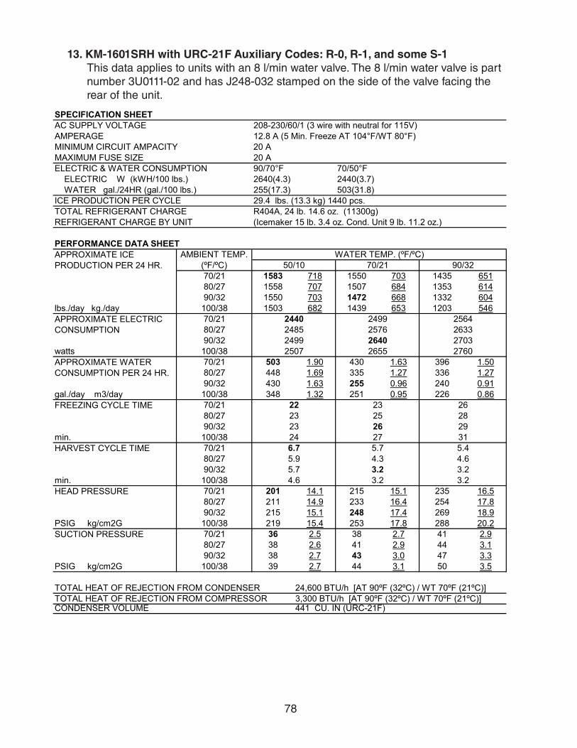
78
13. KM-1601SRH with URC-21F Auxiliary Codes: R-0, R-1, and some S-1This data applies to units with an 8 l/min water valve. The 8 l/min water valve is part number 3U0111-02 and has J248-032 stamped on the side of the valve facing the rear of the unit.
SPECIFICATION SHEETAC SUPPLY VOLTAGE 208-230/60/1 (3 wire with neutral for 115V)AMPERAGE 12.8 A (5 Min. Freeze AT 104°F/WT 80°F)MINIMUM CIRCUIT AMPACITY 20 AMAXIMUM FUSE SIZE 20 AELECTRIC & WATER CONSUMPTION 90/70°F 70/50°F ELECTRIC W (kWH/100 lbs.) 2640(4.3) 2440(3.7) WATER gal./24HR (gal./100 lbs.) 255(17.3) 503(31.8)ICE PRODUCTION PER CYCLE 29.4 lbs. (13.3 kg) 1440 pcs.TOTAL REFRIGERANT CHARGE R404A, 24 lb. 14.6 oz. (11300g)REFRIGERANT CHARGE BY UNIT (Icemaker 15 lb. 3.4 oz. Cond. Unit 9 lb. 11.2 oz.)
PERFORMANCE DATA SHEET
70/21 1583 718 1550 703 1435 65180/27 1558 707 1507 684 1353 61490/32 1550 703 1472 668 1332 604
lbs./day kg./day 100/38 1503 682 1439 653 1203 54670/2180/2790/32
watts 100/3870/21 503 1.90 430 1.63 396 1.5080/27 448 1.69 335 1.27 336 1.2790/32 430 1.63 255 0.96 240 0.91
gal./day m3/day 100/38 348 1.32 251 0.95 226 0.8670/2180/2790/32
min. 100/3870/2180/2790/32
min. 100/3870/21 201 14.1 215 15.1 235 16.580/27 211 14.9 233 16.4 254 17.890/32 215 15.1 248 17.4 269 18.9
PSIG kg/cm2G 100/38 219 15.4 253 17.8 288 20.270/21 36 2.5 38 2.7 41 2.980/27 38 2.6 41 2.9 44 3.190/32 38 2.7 43 3.0 47 3.3
PSIG kg/cm2G 100/38 39 2.7 44 3.1 50 3.5
CONDENSER VOLUME 441 CU. IN (URC-21F)
APPROXIMATE ICE PRODUCTION PER 24 HR.
AMBIENT TEMP. (ºF/ºC)
WATER TEMP. (ºF/ºC)50/10 70/21 90/32
APPROXIMATE ELECTRIC CONSUMPTION
2440 2499 25642485 2576 26332499 2640 27032507 2655 2760
APPROXIMATE WATER CONSUMPTION PER 24 HR.
FREEZING CYCLE TIME 22 23 2623 25 2823 26 2924 27 31
HARVEST CYCLE TIME 6.7 5.7 5.45.9 4.3 4.65.7 3.2 3.2
TOTAL HEAT OF REJECTION FROM COMPRESSOR 3,300 BTU/h [AT 90ºF (32ºC) / WT 70ºF (21ºC)]
4.6 3.2 3.2HEAD PRESSURE
SUCTION PRESSURE
TOTAL HEAT OF REJECTION FROM CONDENSER 24,600 BTU/h [AT 90ºF (32ºC) / WT 70ºF (21ºC)]
ENG.F-011.1.0205
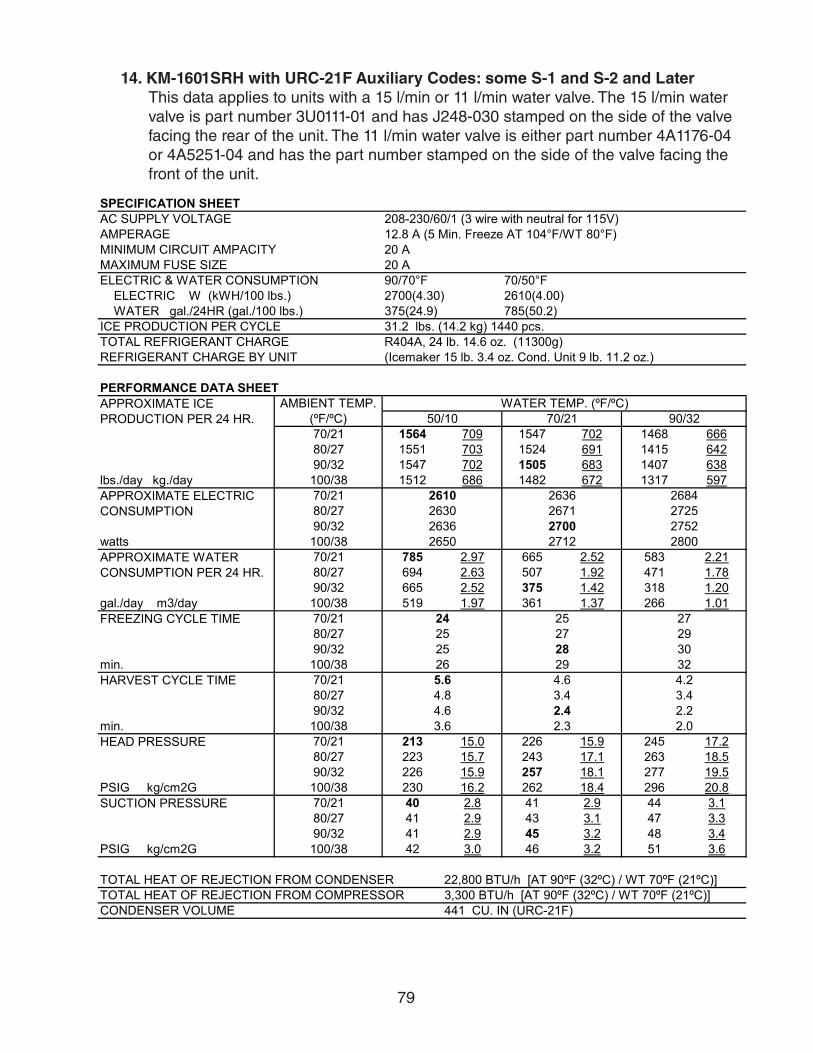
79
14. KM-1601SRH with URC-21F Auxiliary Codes: some S-1 and S-2 and LaterThis data applies to units with a 15 l/min or 11 l/min water valve. The 15 l/min water valve is part number 3U0111-01 and has J248-030 stamped on the side of the valve facing the rear of the unit. The 11 l/min water valve is either part number 4A1176-04 or 4A5251-04 and has the part number stamped on the side of the valve facing the front of the unit.
SPECIFICATION SHEETAC SUPPLY VOLTAGE 208-230/60/1 (3 wire with neutral for 115V)AMPERAGE 12.8 A (5 Min. Freeze AT 104°F/WT 80°F)MINIMUM CIRCUIT AMPACITY 20 AMAXIMUM FUSE SIZE 20 AELECTRIC & WATER CONSUMPTION 90/70°F 70/50°F ELECTRIC W (kWH/100 lbs.) 2700(4.30) 2610(4.00) WATER gal./24HR (gal./100 lbs.) 375(24.9) 785(50.2)ICE PRODUCTION PER CYCLE 31.2 lbs. (14.2 kg) 1440 pcs. TOTAL REFRIGERANT CHARGE R404A, 24 lb. 14.6 oz. (11300g)REFRIGERANT CHARGE BY UNIT (Icemaker 15 lb. 3.4 oz. Cond. Unit 9 lb. 11.2 oz.)
PERFORMANCE DATA SHEET
70/21 1564 709 1547 702 1468 66680/27 1551 703 1524 691 1415 64290/32 1547 702 1505 683 1407 638
lbs./day kg./day 100/38 1512 686 1482 672 1317 59770/2180/2790/32
watts 100/3870/21 785 2.97 665 2.52 583 2.2180/27 694 2.63 507 1.92 471 1.7890/32 665 2.52 375 1.42 318 1.20
gal./day m3/day 100/38 519 1.97 361 1.37 266 1.0170/2180/2790/32
min. 100/3870/2180/2790/32
min. 100/3870/21 213 15.0 226 15.9 245 17.280/27 223 15.7 243 17.1 263 18.590/32 226 15.9 257 18.1 277 19.5
PSIG kg/cm2G 100/38 230 16.2 262 18.4 296 20.870/21 40 2.8 41 2.9 44 3.180/27 41 2.9 43 3.1 47 3.390/32 41 2.9 45 3.2 48 3.4
PSIG kg/cm2G 100/38 42 3.0 46 3.2 51 3.6
CONDENSER VOLUME 441 CU. IN (URC-21F)
APPROXIMATE ICE PRODUCTION PER 24 HR.
AMBIENT TEMP. (ºF/ºC)
WATER TEMP. (ºF/ºC)50/10 70/21 90/32
APPROXIMATE ELECTRIC CONSUMPTION
2610 2636 26842630 2671 27252636 2700 27522650 2712 2800
APPROXIMATE WATER CONSUMPTION PER 24 HR.
FREEZING CYCLE TIME 24 25 2725 27 2925 28 3026 29 32
HARVEST CYCLE TIME 5.6 4.6 4.24.8 3.4 3.44.6 2.4 2.2
TOTAL HEAT OF REJECTION FROM COMPRESSOR 3,300 BTU/h [AT 90ºF (32ºC) / WT 70ºF (21ºC)]
3.6 2.3 2.0HEAD PRESSURE
SUCTION PRESSURE
TOTAL HEAT OF REJECTION FROM CONDENSER 22,800 BTU/h [AT 90ºF (32ºC) / WT 70ºF (21ºC)]
ENG.F-011.1.0205

80
15. KM-1601SRH with URC-22F Auxiliary Codes: S-2 and LaterThis data applies to units with an 11 l/min water valve. The 11 l/min water valve is either part number 4A1176-04 or 4A5251-04 and has the part number stamped on the side of the valve facing the front of the unit.
SPECIFICATION SHEETAC SUPPLY VOLTAGE 208-230/60/1 (3 wire with neutral for 115V)AMPERAGE 12.8 A ( 5 Min. Freeze AT 104°F / WT 80°F)MINIMUM CIRCUIT AMPACITY 20 AMAXIMUM FUSE SIZE 20 AELECTRIC & WATER CONSUMPTION 90/70°F 70/50°F ELECTRIC W (kWH/100 lbs.) 2710(4.36) 2560(4.01) WATER gal./24HR (gal./100 lbs.) 352(23.6) 755(49.3)ICE PRODUCTION PER CYCLE 31.6 lbs. (14.3 kg) 1440 pcs. TOTAL REFRIGERANT CHARGE R404A, 22 lb. 14.8 oz. (10400g)REFRIGERANT CHARGE BY UNIT (Icemaker 15 lb. 3.4 oz. Cond. Unit 7 lb. 11.5 oz.)
PERFORMANCE DATA SHEET
70/21 1531 694 1519 689 1426 64780/27 1522 690 1503 682 1368 62090/32 1519 689 1490 676 1371 622
lbs./day kg./day 100/38 1475 669 1462 663 1261 57270/2180/2790/32
watts 100/3870/21 755 2.86 637 2.41 555 2.1080/27 665 2.52 481 1.82 444 1.6890/32 637 2.41 352 1.33 294 1.11
gal./day m3/day 100/38 493 1.87 338 1.28 241 0.9170/2180/2790/32
min. 100/3870/2180/2790/32
min. 100/3870/21 207 14.5 220 15.5 240 16.980/27 217 15.2 237 16.7 258 18.190/32 220 15.5 252 17.7 273 19.2
PSIG kg/cm2G 100/38 224 15.8 257 18.1 292 20.570/21 40 2.8 42 2.9 44 3.180/27 41 2.9 44 3.1 47 3.390/32 42 2.9 46 3.2 49 3.4
PSIG kg/cm2G 100/38 42 3.0 46 3.3 51 3.6
CONDENSER VOLUME 214 CU. IN (URC-22F)TOTAL HEAT OF REJECTION FROM COMPRESSOR 2,800 BTU/h [AT 90ºF (32ºC) / WT 70ºF (21ºC)]
3.6 2.5 2.0HEAD PRESSURE
SUCTION PRESSURE
TOTAL HEAT OF REJECTION FROM CONDENSER 21,000 BTU/h [AT 90ºF (32ºC) / WT 70ºF (21ºC)]
HARVEST CYCLE TIME 5.5 4.6 4.14.8 3.5 3.44.6 2.6 2.3
3026 29 3127 29 34
2606 2719 2780APPROXIMATE WATER CONSUMPTION PER 24 HR.
FREEZING CYCLE TIME 25 26 2826 28
APPROXIMATE ELECTRIC CONSUMPTION
2560 2604 26452593 2662 26932604 2710 2746
APPROXIMATE ICE PRODUCTION PER 24 HR.
AMBIENT TEMP. (ºF/ºC)
WATER TEMP. (ºF/ºC)50/10 70/21 90/32
ENG.F-011.1.0205

81
16. KM-1601SRH3 with URC-21F Auxiliary Codes: R-0, R-1, and some S-1This data applies to units with an 8 l/min water valve. The 8 l/min water valve is part number 3U0111-02 and has J248-032 stamped on the side of the valve facing the rear of the unit.
SPECIFICATION SHEETAC SUPPLY VOLTAGE 208-230/60/3AMPERAGE 7.9 A (5 Min. Freeze AT 104°F/WT 80°F)MINIMUM CIRCUIT AMPACITY 20 AMAXIMUM FUSE SIZE 20 AELECTRIC & WATER CONSUMPTION 90/70°F 70/50°F ELECTRIC W (kWH/100 lbs.) 2580(4.3) 2450(3.7) WATER gal./24HR (gal./100 lbs.) 261(17.9) 504(31.6)ICE PRODUCTION PER CYCLE 29.4 lbs. (13.3 kg) 1440 pcs.TOTAL REFRIGERANT CHARGE R404A, 24 lb. 14.6 oz. (11300g)REFRIGERANT CHARGE BY UNIT (Icemaker 15 lb. 3.4 oz. Cond. Unit 9 lb. 11.2 oz.)
PERFORMANCE DATA SHEET
70/21 1596 724 1556 706 1436 65180/27 1565 710 1503 682 1347 61190/32 1556 706 1459 662 1316 597
lbs./day kg./day 100/38 1510 685 1426 647 1184 53770/2180/2790/32
watts 100/3870/21 504 1.91 433 1.64 396 1.5080/27 450 1.70 339 1.28 336 1.2790/32 433 1.64 261 0.99 243 0.92
gal./day m3/day 100/38 351 1.33 256 0.97 226 0.8670/2180/2790/32
min. 100/3870/2180/2790/32
min. 100/3870/21 202 14.2 215 15.1 237 16.780/27 212 14.9 233 16.3 257 18.190/32 215 15.1 247 17.4 271 19.1
PSIG kg/cm2G 100/38 221 15.5 253 17.8 293 20.670/21 37 2.6 39 2.7 42 3.080/27 38 2.7 41 2.9 45 3.290/32 39 2.7 43 3.0 47 3.3
PSIG kg/cm2G 100/38 40 2.8 44 3.1 51 3.6
CONDENSER VOLUME 441 CU. IN (URC-21F)
APPROXIMATE ICE PRODUCTION PER 24 HR.
208-230/60/3 (3 wire with neutral
WATER TEMP. (ºF/ºC)50/10 70/21 90/32
APPROXIMATE ELECTRIC CONSUMPTION
2450 2488 25552479 2538 26132488 2580 26532506 2597 2720
APPROXIMATE WATER CONSUMPTION PER 24 HR.
FREEZING CYCLE TIME 22 23 2623 25 2823 26 2924 27 32
HARVEST CYCLE TIME 6.6 5.6 5.35.8 4.3 4.55.6 3.2 3.2
TOTAL HEAT OF REJECTION FROM COMPRESSOR 3,200 BTU/h [AT 90ºF (32ºC) / WT 70ºF (21ºC)]
4.5 3.2 3.2HEAD PRESSURE
SUCTION PRESSURE
TOTAL HEAT OF REJECTION FROM CONDENSER 24,300 BTU/h [AT 90ºF (32ºC) / WT 70ºF (21ºC)]
ENG.F-011.1.0205

82
17. KM-1601SRH3 with URC-21F Auxiliary Codes: some S-1 and S-2 and LaterThis data applies to units with a 15 l/min or 11 l/min water valve. The 15 l/min water valve is part number 3U0111-01 and has J248-030 stamped on the side of the valve facing the rear of the unit. The 11 l/min water valve is either part number 4A1176-04 or 4A5251-04 and has the part number stamped on the side of the valve facing the front of the unit.
SPECIFICATION SHEETAC SUPPLY VOLTAGE 208-230/60/3AMPERAGE 7.9 A ( 5 Min. Freeze AT 104°F / WT 80°F)MINIMUM CIRCUIT AMPACITY 20 AMAXIMUM FUSE SIZE 20 AELECTRIC & WATER CONSUMPTION 90/70°F 70/50°F ELECTRIC W (kWH/100 lbs.) 2960(4.70) 2580(3.90) WATER gal./24HR (gal./100 lbs.) 363(24.0) 781(49.3)ICE PRODUCTION PER CYCLE 31.2 lbs. (14.2 kg) 1440 pcs. TOTAL REFRIGERANT CHARGE R404A, 24 lb. 14.6 oz. (11300g)REFRIGERANT CHARGE BY UNIT (Icemaker 15 lb. 3.4 oz. Cond. Unit 9 lb. 11.2 oz.)
PERFORMANCE DATA SHEET
70/21 1585 719 1563 709 1464 66480/27 1568 711 1535 696 1396 63390/32 1563 709 1511 685 1387 629
lbs./day kg./day 100/38 1520 689 1482 672 1273 57770/2180/2790/32
watts 100/3870/21 781 2.96 659 2.49 585 2.2180/27 688 2.60 497 1.88 476 1.8090/32 659 2.49 363 1.37 318 1.20
gal./day m3/day 100/38 514 1.95 352 1.33 276 1.0570/2180/2790/32
min. 100/3870/2180/2790/32
min. 100/3870/21 202 14.2 215 15.1 237 16.780/27 212 14.9 233 16.3 257 18.190/32 215 15.1 247 17.4 271 19.1
PSIG kg/cm2G 100/38 221 15.5 253 17.8 293 20.670/21 37 2.6 39 2.7 42 3.080/27 38 2.7 41 2.9 45 3.290/32 39 2.7 43 3.0 47 3.3
PSIG kg/cm2G 100/38 40 2.8 44 3.1 51 3.6
CONDENSER VOLUME 441 CU. IN (URC-21F)
APPROXIMATE ICE PRODUCTION PER 24 HR.
AMBIENT TEMP. (ºF/ºC)
WATER TEMP. (ºF/ºC)50/10 70/21 90/32
APPROXIMATE ELECTRIC CONSUMPTION
2580 2691 27122665 2838 27852691 2960 29392651 2955 2920
APPROXIMATE WATER CONSUMPTION PER 24 HR.
FREEZING CYCLE TIME 24 25 2725 27 2925 28 3026 29 32
HARVEST CYCLE TIME 5.5 4.6 4.14.8 3.4 3.44.6 2.4 2.2
TOTAL HEAT OF REJECTION FROM COMPRESSOR 3,200 BTU/h [AT 90ºF (32ºC) / WT 70ºF (21ºC)]
3.6 2.4 2.0HEAD PRESSURE
SUCTION PRESSURE
TOTAL HEAT OF REJECTION FROM CONDENSER 22,000 BTU/h [AT 90ºF (32ºC) / WT 70ºF (21ºC)]
ENG.F-011.1.0205

83
18. KM-1601SRH3 with URC-22F Auxiliary Codes: S-2 and LaterThis data applies to units with an 11 l/min water valve. The 11 l/min water valve is either part number 4A1176-04 or 4A5251-04 and has the part number stamped on the side of the valve facing the front of the unit.
SPECIFICATION SHEETAC SUPPLY VOLTAGE 208-230/60/3AMPERAGE 7.9 A (5 Min. Freeze AT 104°F/WT 80°F)MINIMUM CIRCUIT AMPACITY 20 AMAXIMUM FUSE SIZE 20 AELECTRIC & WATER CONSUMPTION 90/70°F 70/50°F ELECTRIC W (kWH/100 lbs.) 2780(4.46) 2490(3.90) WATER gal./24HR (gal./100 lbs.) 348(23.2) 704(46.0)ICE PRODUCTION PER CYCLE 32.1 lbs. (14.6 kg) 1440 pcs. TOTAL REFRIGERANT CHARGE R404A, 22 lb. 14.8 oz. (10400g)REFRIGERANT CHARGE BY UNIT (Icemaker 15 lb. 3.4 oz. Cond. Unit 7 lb. 11.5 oz.)
PERFORMANCE DATA SHEET
70/21 1530 694 1521 690 1414 64180/27 1523 691 1508 684 1349 61290/32 1521 690 1498 679 1359 616
lbs./day kg./day 100/38 1468 666 1465 665 1231 55870/2180/2790/32
watts 100/3870/21 704 2.66 599 2.27 531 2.0180/27 624 2.36 462 1.75 435 1.6590/32 599 2.27 348 1.32 301 1.14
gal./day m3/day 100/38 474 1.79 337 1.27 259 0.9870/2180/2790/32
min. 100/3870/2180/2790/32
min. 100/3870/21 220 15.4 237 16.7 244 17.280/27 233 16.4 260 18.3 258 18.290/32 237 16.7 279 19.6 281 19.8
PSIG kg/cm2G 100/38 233 16.4 279 19.6 283 19.970/21 40 2.8 42 3.0 45 3.280/27 42 2.9 45 3.2 48 3.490/32 42 3.0 47.6 3.3 50 3.5
PSIG kg/cm2G 100/38 43 3.0 48 3.4 53 3.7
CONDENSER VOLUME 214 CU. IN (URC-22F)TOTAL HEAT OF REJECTION FROM COMPRESSOR 3,500 BTU/h [AT 90ºF (32ºC) / WT 70ºF (21ºC)]
3.6 2.6 2.2HEAD PRESSURE
SUCTION PRESSURE
TOTAL HEAT OF REJECTION FROM CONDENSER 26,400 BTU/h [AT 90ºF (32ºC) / WT 70ºF (21ºC)]
HARVEST CYCLE TIME 5.3 4.5 4.14.7 3.5 3.44.5 2.7 2.4
3127 29 3227 30 34
2548 2779 2770APPROXIMATE WATER CONSUMPTION PER 24 HR.
FREEZING CYCLE TIME 26 27 2926 28
APPROXIMATE ELECTRIC CONSUMPTION
2490 2575 25992555 2687 26592575 2780 2775
APPROXIMATE ICE PRODUCTION PER 24 HR.
AMBIENT TEMP. (ºF/ºC)
WATER TEMP. (ºF/ºC)50/10 70/21 90/32
ENG.F-011.1.0205

84
19. KM-1900SAH
SPECIFICATION SHEETAC SUPPLY VOLTAGE 208-230/60/1 (3 wire with neutral 115V)AMPERAGE 14.4 A (5 Min. Freeze AT 104°F / WT 80°F)MINIMUM CIRCUIT AMPACITY 30 AMAXIMUM FUSE SIZE 30 AELECTRIC & WATER CONSUMPTION 90/70°F 70/50°F ELECTRIC W (kWH/100 lbs.) 2670(4.1) 2480(3.2) WATER gal./24HR (gal./100 lbs.) 293(18.8) 579(31.0)ICE PRODUCTION PER CYCLE 45.3 lbs. (20.5 kg) 2160pcs.REFRIGERANT CHARGE R404A, 4 lb. 10.1 oz. (2100g)
PERFORMANCE DATA SHEET
70/21 1867 847 1777 806 1638 74380/27 1798 816 1659 752 1511 68590/32 1777 806 1560 708 1413 641
lbs./day kg./day 100/38 1744 791 1526 692 1278 58070/2180/2790/32
watts 100/3870/21 579 2.19 495 1.88 444 1.6880/27 515 1.95 385 1.46 369 1.4090/32 495 1.88 293 1.11 261 0.99
gal./day m3/day 100/38 396 1.50 286 1.08 232 0.8870/2180/2790/32
min. 100/3870/2180/2790/32
min. 100/3870/21 241 16.9 263 18.5 288 20.380/27 258 18.1 291 20.5 314 22.190/32 263 18.5 315 22.1 339 23.9
PSIG kg/cm2G 100/38 266 18.7 321 22.6 362 25.570/21 49 3.4 50 3.5 52 3.780/27 50 3.5 52 3.6 54 3.890/32 50 3.5 53 3.7 55 3.9
PSIG kg/cm2G 100/38 51 3.6 53 3.8 57 4.0
23,800 BTU/h [AT 90ºF (32ºC) / WT 70ºF (21ºC)]
APPROXIMATE ICE PRODUCTION PER 24 HR.
AMBIENT TEMP. (ºF/ºC)
WATER TEMP. (ºF/ºC)50/10 70/21 90/32
APPROXIMATE ELECTRIC CONSUMPTION
2480 2536 25732522 2609 26252536 2670 26962530 2676 2720
APPROXIMATE WATER CONSUMPTION PER 24 HR.
FREEZING CYCLE TIME 32 34 3934 37 4234 40 4436 41 49
HARVEST CYCLE TIME 4.8 4.2 4.04.4 3.4 3.54.2 2.8 2.73.6 2.7 2.7
HEAD PRESSURE
SUCTION PRESSURE
TOTAL HEAT OF REJECTION FROM CONDENSER
ENG.F-011.1.0205
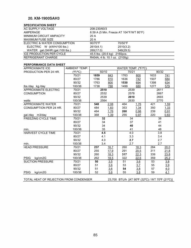
85
20. KM-1900SAH3
SPECIFICATION SHEETAC SUPPLY VOLTAGE 208-230/60/3AMPERAGE 8.59 A (5 Min. Freeze AT 104°F/WT 80°F)MINIMUM CIRCUIT AMPACITY 20 AMAXIMUM FUSE SIZE 20 AELECTRIC & WATER CONSUMPTION 90/70°F 70/50°F ELECTRIC W (kWH/100 lbs.) 2610(4.1) 2510(3.2) WATER gal./24HR (gal./100 lbs.) 260(17.0) 548(29.5)ICE PRODUCTION PER CYCLE 45.5 lbs. (20.6 kg) 2160pcs.REFRIGERANT CHARGE R404A, 4 lb. 10.1 oz. (2100g)
PERFORMANCE DATA SHEET
70/21 1859 843 1763 800 1633 74180/27 1786 810 1636 742 1507 68490/32 1763 800 1530 694 1398 634
lbs./day kg./day 100/38 1738 788 1499 680 1277 57970/2180/2790/32
watts 100/3870/21 548 2.08 464 1.76 421 1.5980/27 484 1.83 353 1.34 350 1.3390/32 464 1.76 260 0.98 239 0.91
gal./day m3/day 100/38 368 1.39 255 0.97 220 0.8370/2180/2790/32
min. 100/3870/2180/2790/32
min. 100/3870/21 237 16.7 260 18.3 284 20.080/27 255 17.9 291 20.5 311 21.890/32 260 18.3 317 22.3 339 23.8
PSIG kg/cm2G 100/38 262 18.5 322 22.6 359 25.270/21 50 3.5 51 3.6 53 3.880/27 51 3.6 53 3.7 55 3.990/32 51 3.6 54 3.8 57 4.0
PSIG kg/cm2G 100/38 52 3.6 55 3.8 59 4.1
23,700 BTU/h [AT 90ºF (32ºC) / WT 70ºF (21ºC)]
APPROXIMATE ICE PRODUCTION PER 24 HR.
AMBIENT TEMP. (ºF/ºC)
WATER TEMP. (ºF/ºC)50/10 70/21 90/32
APPROXIMATE ELECTRIC CONSUMPTION
2510 2539 26112532 2578 26672539 2610 26932564 2630 2770
APPROXIMATE WATER CONSUMPTION PER 24 HR.
FREEZING CYCLE TIME 32 34 3834 37 4134 40 4435 41 48
HARVEST CYCLE TIME 4.5 4.0 3.84.1 3.3 3.44.0 2.7 2.73.4 2.7 2.7
HEAD PRESSURE
SUCTION PRESSURE
TOTAL HEAT OF REJECTION FROM CONDENSER
ENG.F-011.1.0205

86
21. KM-1900SWH
SPECIFICATION SHEETAC SUPPLY VOLTAGE 208-230/60/1 (3 wire with neutral 115V)AMPERAGE 12.5 A (5 Min. Freeze AT 104°F/WT 80°F)MINIMUM CIRCUIT AMPACITY 30 AMAXIMUM FUSE SIZE 30 AELECTRIC & WATER CONSUMPTION 90/70°F 70/50°F ELECTRIC W (kWH/100 lbs.) 2390(3.1) 2330(3.0) POTABLE WATER gal./24HR (gal./100 lbs.) 348(18.8) 628(33.5) WATER COOLED CONDENSER 1832(99) 1022(55)gal./24HR (gal./100 lbs.)ICE PRODUCTION PER CYCLE 47 lbs. (21.3 kg) 2160pcs.REFRIGERANT CHARGE R404A, 3 lb. 1.4 oz. (1400g)
PERFORMANCE DATA SHEET
70/21 1876 851 1868 847 1734 78780/27 1870 848 1858 843 1655 75190/32 1868 847 1850 839 1673 759
lbs./day kg./day 100/38 1800 816 1809 820 1511 68570/2180/2790/32
watts 100/3870/21 1650 6.25 1805 6.83 2168 8.2180/27 1768 6.69 2009 7.61 2455 9.2990/32 1805 6.83 2179 8.25 2598 9.83
gal./day m3/day 100/38 2103 7.96 2277 8.62 2983 11.2970/2180/2790/32
min. 100/3870/2180/2790/32
min. 100/3870/21 238 16.7 241 17.0 254 17.980/27 240 16.9 245 17.3 263 18.590/32 241 17.0 249 17.5 265 18.6
PSIG kg/cm2G 100/38 247 17.3 253 17.8 279 19.670/21 49 3.4 49 3.5 51 3.680/27 49 3.5 50 3.5 51 3.690/32 49 3.5 50 3.5 52 3.6
PSIG kg/cm2G 100/38 50 3.5 50 3.5 53 3.7
26,800 BTU/h [AT 90ºF (32ºC) / WT 70ºF (21ºC)]TOTAL HEAT OF REJECTION FROM COMPRESSOR 3,200 BTU/h [AT 90ºF (32ºC) / WT 70ºF (21ºC)]WATER FLOW FOR CONDENSER 113 gal./h [AT 100ºF (38ºC) / WT 90ºF (32ºC)]PRESSURE DROP OF COOLING WATER LINE less than 10 PSIG
3.5 2.8 2.7HEAD PRESSURE
SUCTION PRESSURE
TOTAL HEAT OF REJECTION FROM CONDENSER
HARVEST CYCLE TIME 4.6 4.1 3.94.2 3.4 3.44.1 2.8 2.7
3733 35 3834 35 41
2355 2397 2450APPROXIMATE WATER CONSUMPTION PER 24 HR.
FREEZING CYCLE TIME 32 33 3533 34
APPROXIMATE ELECTRIC CONSUMPTION
2330 2348 23772343 2371 24032348 2390 2421
APPROXIMATE ICE PRODUCTION PER 24 HR.
AMBIENT TEMP. (ºF/ºC)
WATER TEMP. (ºF/ºC)50/10 70/21 90/32
ENG.F-011.1.0205

87
22. KM-1900SWH3
SPECIFICATION SHEETAC SUPPLY VOLTAGE 208-230/60/3AMPERAGE 8.4 A (5 Min. Freeze AT 104°F/WT 80°F)MINIMUM CIRCUIT AMPACITY 20 AMAXIMUM FUSE SIZE 20 AELECTRIC & WATER CONSUMPTION 90/70°F 70/50°F ELECTRIC W (kWH/100 lbs.) 2490(3.3) 2410(3.2) POTABLE WATER gal./24HR (gal./100 lbs.) 341(18.8) 584(32.0) WATER COOLED CONDENSER 1796(99) 982(54)gal./24HR (gal./100 lbs.)ICE PRODUCTION PER CYCLE 45.4 lbs. (20.6 kg) 2160pcs.REFRIGERANT CHARGE R404A, 3 lb. 1.4 oz. (1400g)
PERFORMANCE DATA SHEET
70/21 1825 828 1822 826 1693 76880/27 1823 827 1818 824 1619 73490/32 1822 826 1814 823 1642 745
lbs./day kg./day 100/38 1754 796 1774 805 1484 67370/2180/2790/32
watts 100/3870/21 1566 5.93 1733 6.56 2144 8.1280/27 1693 6.41 1953 7.39 2465 9.3390/32 1733 6.56 2137 8.09 2615 9.90
gal./day m3/day 100/38 2063 7.81 2249 8.51 3054 11.5670/2180/2790/32
min. 100/3870/2180/2790/32
min. 100/3870/21 239 16.8 241 16.9 255 17.980/27 241 16.9 244 17.1 264 18.590/32 241 16.9 246 17.3 264 18.5
PSIG kg/cm2G 100/38 248 17.4 250 17.6 280 19.770/21 50 3.5 50 3.5 51 3.680/27 50 3.5 50 3.5 52 3.690/32 50 3.5 50 3.5 52 3.6
PSIG kg/cm2G 100/38 51 3.6 50 3.5 53 3.7
27,100 BTU/h [AT 90ºF (32ºC) / WT 70ºF (21ºC)]TOTAL HEAT OF REJECTION FROM COMPRESSOR 3,200 BTU/h [AT 90ºF (32ºC) / WT 70ºF (21ºC)]WATER FLOW FOR CONDENSER 117 gal./h [AT 100ºF (38ºC) / WT 90ºF (32ºC)]PRESSURE DROP OF COOLING WATER LINE less than 10 PSIG
APPROXIMATE ICE PRODUCTION PER 24 HR.
AMBIENT TEMP. (ºF/ºC)
WATER TEMP. (ºF/ºC)50/10 70/21 90/32
APPROXIMATE ELECTRIC CONSUMPTION
2410 2433 24612428 2464 24892433 2490 25162437 2496 2540
APPROXIMATE WATER CONSUMPTION PER 24 HR.
FREEZING CYCLE TIME 32 33 3532 34 3733 34 3834 35 41
HARVEST CYCLE TIME 4.7 4.1 3.94.2 3.4 3.54.1 2.7 2.73.5 2.7 2.7
HEAD PRESSURE
SUCTION PRESSURE
TOTAL HEAT OF REJECTION FROM CONDENSER
ENG.F-011.1.0205
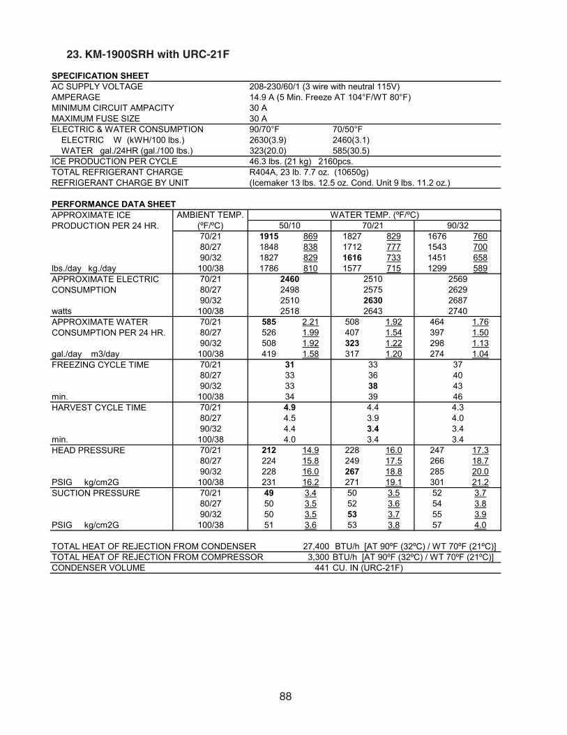
88
23. KM-1900SRH with URC-21F
SPECIFICATION SHEETAC SUPPLY VOLTAGE 208-230/60/1 (3 wire with neutral 115V)AMPERAGE 14.9 A (5 Min. Freeze AT 104°F/WT 80°F)MINIMUM CIRCUIT AMPACITY 30 AMAXIMUM FUSE SIZE 30 AELECTRIC & WATER CONSUMPTION 90/70°F 70/50°F ELECTRIC W (kWH/100 lbs.) 2630(3.9) 2460(3.1) WATER gal./24HR (gal./100 lbs.) 323(20.0) 585(30.5)ICE PRODUCTION PER CYCLE 46.3 lbs. (21 kg) 2160pcs.TOTAL REFRIGERANT CHARGE R404A, 23 lb. 7.7 oz. (10650g)REFRIGERANT CHARGE BY UNIT (Icemaker 13 lbs. 12.5 oz. Cond. Unit 9 lbs. 11.2 oz.)
PERFORMANCE DATA SHEET
70/21 1915 869 1827 829 1676 76080/27 1848 838 1712 777 1543 70090/32 1827 829 1616 733 1451 658
lbs./day kg./day 100/38 1786 810 1577 715 1299 58970/2180/2790/32
watts 100/3870/21 585 2.21 508 1.92 464 1.7680/27 526 1.99 407 1.54 397 1.5090/32 508 1.92 323 1.22 298 1.13
gal./day m3/day 100/38 419 1.58 317 1.20 274 1.0470/2180/2790/32
min. 100/3870/2180/2790/32
min. 100/3870/21 212 14.9 228 16.0 247 17.380/27 224 15.8 249 17.5 266 18.790/32 228 16.0 267 18.8 285 20.0
PSIG kg/cm2G 100/38 231 16.2 271 19.1 301 21.270/21 49 3.4 50 3.5 52 3.780/27 50 3.5 52 3.6 54 3.890/32 50 3.5 53 3.7 55 3.9
PSIG kg/cm2G 100/38 51 3.6 53 3.8 57 4.0
27,400 BTU/h [AT 90ºF (32ºC) / WT 70ºF (21ºC)]3,300 BTU/h [AT 90ºF (32ºC) / WT 70ºF (21ºC)]
CONDENSER VOLUME 441 CU. IN (URC-21F)
APPROXIMATE ICE PRODUCTION PER 24 HR.
AMBIENT TEMP. (ºF/ºC)
WATER TEMP. (ºF/ºC)50/10 70/21 90/32
APPROXIMATE ELECTRIC CONSUMPTION
2460 2510 25692498 2575 26292510 2630 26872518 2643 2740
APPROXIMATE WATER CONSUMPTION PER 24 HR.
FREEZING CYCLE TIME 31 33 3733 36 4033 38 4334 39 46
HARVEST CYCLE TIME 4.9 4.4 4.34.5 3.9 4.04.4 3.4 3.4
TOTAL HEAT OF REJECTION FROM COMPRESSOR
4.0 3.4 3.4HEAD PRESSURE
SUCTION PRESSURE
TOTAL HEAT OF REJECTION FROM CONDENSER
ENG.F-011.1.0205

89
24. KM-1900SRH with URC-22F
SPECIFICATION SHEETAC SUPPLY VOLTAGE 208-230/60/1 (3 wire with neutral 115V)AMPERAGE 14.9 A (5 Min. Freeze AT 104°F/WT 80°F)MINIMUM CIRCUIT AMPACITY 30 AMAXIMUM FUSE SIZE 30 AELECTRIC & WATER CONSUMPTION 90/70°F 70/50°F ELECTRIC W (kWH/100 lbs.) 2790(4.09) 2500(3.23) WATER gal./24HR (gal./100 lbs.) 328(20.0) 609(32.8)ICE PRODUCTION PER CYCLE 46 lbs. (20.9 kg) 2160pcs.TOTAL REFRIGERANT CHARGE R404A, 21 lb. 7.9 oz. (9750g)REFRIGERANT CHARGE BY UNIT (Icemaker 13 lbs. 12.5 oz. Cond. Unit 7 lbs. 11.5 oz.)
PERFORMANCE DATA SHEET
70/21 1857 842 1793 814 1636 74280/27 1809 820 1710 776 1514 68790/32 1793 814 1640 744 1457 661
lbs./day kg./day 100/38 1738 789 1597 724 1289 58570/2180/2790/32
watts 100/3870/21 609 2.30 527 1.99 474 1.7980/27 546 2.07 418 1.58 399 1.5190/32 527 1.99 328 1.24 293 1.11
gal./day m3/day 100/38 428 1.62 320 1.21 262 0.9970/2180/2790/32
min. 100/3870/2180/2790/32
min. 100/3870/21 207 14.6 224 15.7 241 17.080/27 220 15.4 246 17.3 260 18.390/32 224 15.7 264 18.6 280 19.7
PSIG kg/cm2G 100/38 225 15.8 268 18.8 295 20.770/21 49 3.4 50 3.5 51 3.680/27 49 3.5 50 3.5 53 3.790/32 50 3.5 51 3.6 53 3.7
PSIG kg/cm2G 100/38 50 3.5 51 3.6 55 3.9
26,500 BTU/h [AT 90ºF (32ºC) / WT 70ºF (21ºC)]3,200 BTU/h [AT 90ºF (32ºC) / WT 70ºF (21ºC)]
CONDENSER VOLUME 214 CU. IN (URC-22F)
APPROXIMATE ICE PRODUCTION PER 24 HR.
AMBIENT TEMP. (ºF/ºC)
WATER TEMP. (ºF/ºC)50/10 70/21 90/32
APPROXIMATE ELECTRIC CONSUMPTION
2500 2585 26052565 2697 26632585 2790 27802556 2788 2770
APPROXIMATE WATER CONSUMPTION PER 24 HR.
FREEZING CYCLE TIME 32 34 3834 36 4134 38 4235 39 46
HARVEST CYCLE TIME 5.4 4.9 4.65.0 4.1 4.24.9 3.5 3.4
TOTAL HEAT OF REJECTION FROM COMPRESSOR
4.2 3.5 3.4HEAD PRESSURE
SUCTION PRESSURE
TOTAL HEAT OF REJECTION FROM CONDENSER
ENG.F-011.1.0205

90
25. KM-1900SRH3 with URC-21F
SPECIFICATION SHEETAC SUPPLY VOLTAGE 208-230/60/3AMPERAGE 11.0 A ( 5 Min. Freeze AT 104°F / WT 80°F)MINIMUM CIRCUIT AMPACITY 20 AMAXIMUM FUSE SIZE 20 AELECTRIC & WATER CONSUMPTION 90/70°F 70/50°F ELECTRIC W (kWH/100 lbs.) 2840(4.1) 2680(3.3) WATER gal./24HR (gal./100 lbs.) 332(20.0) 590(30.0)ICE PRODUCTION PER CYCLE 46.5 lbs. (21.1 kg) 2160pcs.TOTAL REFRIGERANT CHARGE R404A, 23 lb. 7.7 oz. (10650g)REFRIGERANT CHARGE BY UNIT (Icemaker 13 lbs. 12.5 oz. Cond. Unit 9 lbs. 11.2 oz.)
PERFORMANCE DATA SHEET
70/21 1965 891 1876 851 1708 77580/27 1897 860 1758 797 1566 71090/32 1876 851 1660 753 1474 669
lbs./day kg./day 100/38 1827 829 1617 733 1304 59170/2180/2790/32
watts 100/3870/21 590 2.23 515 1.95 469 1.7780/27 533 2.02 415 1.57 401 1.5290/32 515 1.95 332 1.26 304 1.15
gal./day m3/day 100/38 425 1.61 325 1.23 278 1.0570/2180/2790/32
min. 100/3870/2180/2790/32
min. 100/3870/21 202 14.2 219 15.4 236 16.680/27 215 15.1 241 16.9 255 17.990/32 219 15.4 259 18.2 275 19.3
PSIG kg/cm2G 100/38 220 15.5 263 18.5 289 20.370/21 49 3.4 50 3.5 51 3.680/27 49 3.5 50 3.5 53 3.790/32 50 3.5 51 3.6 53 3.7
PSIG kg/cm2G 100/38 50 3.5 51 3.6 55 3.9
26,100 BTU/h [AT 90ºF (32ºC) / WT 70ºF (21ºC)]3,200 BTU/h [AT 90ºF (32ºC) / WT 70ºF (21ºC)]
CONDENSER VOLUME 441 CU. IN (URC-21F)
APPROXIMATE ICE PRODUCTION PER 24 HR.
AMBIENT TEMP. (ºF/ºC)
WATER TEMP. (ºF/ºC)50/10 70/21 90/32
APPROXIMATE ELECTRIC CONSUMPTION
2680 2727 27892716 2789 28492727 2840 29032738 2855 2960
APPROXIMATE WATER CONSUMPTION PER 24 HR.
FREEZING CYCLE TIME 31 33 3733 36 4033 38 4234 39 46
HARVEST CYCLE TIME 4.9 4.4 4.34.5 3.8 4.04.4 3.4 3.4
TOTAL HEAT OF REJECTION FROM COMPRESSOR
4.0 3.4 3.4HEAD PRESSURE
SUCTION PRESSURE
TOTAL HEAT OF REJECTION FROM CONDENSER
ENG.F-011.1.0205
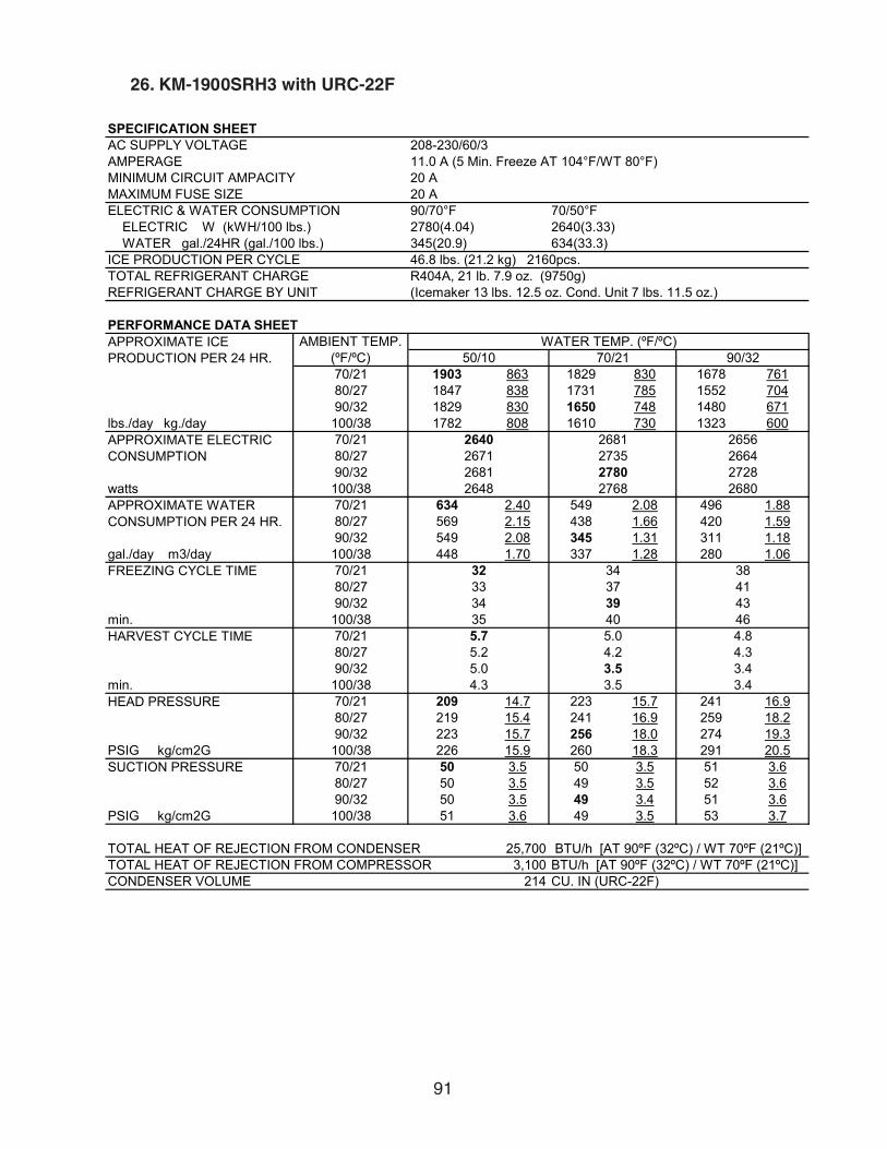
91
26. KM-1900SRH3 with URC-22F
SPECIFICATION SHEETAC SUPPLY VOLTAGE 208-230/60/3AMPERAGE 11.0 A (5 Min. Freeze AT 104°F/WT 80°F)MINIMUM CIRCUIT AMPACITY 20 AMAXIMUM FUSE SIZE 20 AELECTRIC & WATER CONSUMPTION 90/70°F 70/50°F ELECTRIC W (kWH/100 lbs.) 2780(4.04) 2640(3.33) WATER gal./24HR (gal./100 lbs.) 345(20.9) 634(33.3)ICE PRODUCTION PER CYCLE 46.8 lbs. (21.2 kg) 2160pcs.TOTAL REFRIGERANT CHARGE R404A, 21 lb. 7.9 oz. (9750g)REFRIGERANT CHARGE BY UNIT (Icemaker 13 lbs. 12.5 oz. Cond. Unit 7 lbs. 11.5 oz.)
PERFORMANCE DATA SHEET
70/21 1903 863 1829 830 1678 76180/27 1847 838 1731 785 1552 70490/32 1829 830 1650 748 1480 671
lbs./day kg./day 100/38 1782 808 1610 730 1323 60070/2180/2790/32
watts 100/3870/21 634 2.40 549 2.08 496 1.8880/27 569 2.15 438 1.66 420 1.5990/32 549 2.08 345 1.31 311 1.18
gal./day m3/day 100/38 448 1.70 337 1.28 280 1.0670/2180/2790/32
min. 100/3870/2180/2790/32
min. 100/3870/21 209 14.7 223 15.7 241 16.980/27 219 15.4 241 16.9 259 18.290/32 223 15.7 256 18.0 274 19.3
PSIG kg/cm2G 100/38 226 15.9 260 18.3 291 20.570/21 50 3.5 50 3.5 51 3.680/27 50 3.5 49 3.5 52 3.690/32 50 3.5 49 3.4 51 3.6
PSIG kg/cm2G 100/38 51 3.6 49 3.5 53 3.7
25,700 BTU/h [AT 90ºF (32ºC) / WT 70ºF (21ºC)]3,100 BTU/h [AT 90ºF (32ºC) / WT 70ºF (21ºC)]
CONDENSER VOLUME 214 CU. IN (URC-22F)TOTAL HEAT OF REJECTION FROM COMPRESSOR
4.3 3.5 3.4HEAD PRESSURE
SUCTION PRESSURE
TOTAL HEAT OF REJECTION FROM CONDENSER
HARVEST CYCLE TIME 5.7 5.0 4.85.2 4.2 4.35.0 3.5 3.4
4134 39 4335 40 46
2648 2768 2680APPROXIMATE WATER CONSUMPTION PER 24 HR.
FREEZING CYCLE TIME 32 34 3833 37
APPROXIMATE ELECTRIC CONSUMPTION
2640 2681 26562671 2735 26642681 2780 2728
APPROXIMATE ICE PRODUCTION PER 24 HR.
AMBIENT TEMP. (ºF/ºC)
WATER TEMP. (ºF/ºC)50/10 70/21 90/32
ENG.F-011.1.0205
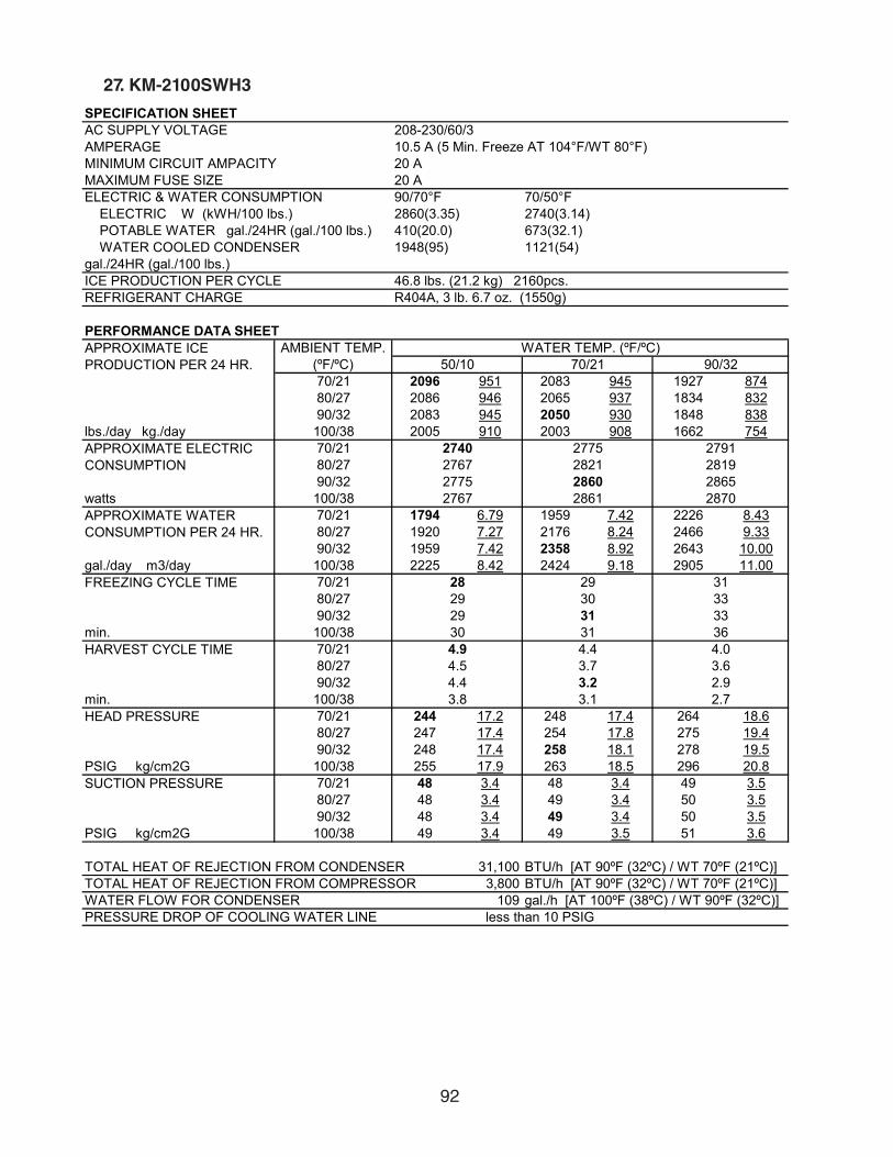
92
27. KM-2100SWH3
SPECIFICATION SHEETAC SUPPLY VOLTAGE 208-230/60/3AMPERAGE 10.5 A (5 Min. Freeze AT 104°F/WT 80°F)MINIMUM CIRCUIT AMPACITY 20 AMAXIMUM FUSE SIZE 20 AELECTRIC & WATER CONSUMPTION 90/70°F 70/50°F ELECTRIC W (kWH/100 lbs.) 2860(3.35) 2740(3.14) POTABLE WATER gal./24HR (gal./100 lbs.) 410(20.0) 673(32.1) WATER COOLED CONDENSER 1948(95) 1121(54)gal./24HR (gal./100 lbs.)ICE PRODUCTION PER CYCLE 46.8 lbs. (21.2 kg) 2160pcs.REFRIGERANT CHARGE R404A, 3 lb. 6.7 oz. (1550g)
PERFORMANCE DATA SHEET
70/21 2096 951 2083 945 1927 87480/27 2086 946 2065 937 1834 83290/32 2083 945 2050 930 1848 838
lbs./day kg./day 100/38 2005 910 2003 908 1662 75470/2180/2790/32
watts 100/3870/21 1794 6.79 1959 7.42 2226 8.4380/27 1920 7.27 2176 8.24 2466 9.3390/32 1959 7.42 2358 8.92 2643 10.00
gal./day m3/day 100/38 2225 8.42 2424 9.18 2905 11.0070/2180/2790/32
min. 100/3870/2180/2790/32
min. 100/3870/21 244 17.2 248 17.4 264 18.680/27 247 17.4 254 17.8 275 19.490/32 248 17.4 258 18.1 278 19.5
PSIG kg/cm2G 100/38 255 17.9 263 18.5 296 20.870/21 48 3.4 48 3.4 49 3.580/27 48 3.4 49 3.4 50 3.590/32 48 3.4 49 3.4 50 3.5
PSIG kg/cm2G 100/38 49 3.4 49 3.5 51 3.6
31,100 BTU/h [AT 90ºF (32ºC) / WT 70ºF (21ºC)]TOTAL HEAT OF REJECTION FROM COMPRESSOR 3,800 BTU/h [AT 90ºF (32ºC) / WT 70ºF (21ºC)]WATER FLOW FOR CONDENSER 109 gal./h [AT 100ºF (38ºC) / WT 90ºF (32ºC)]PRESSURE DROP OF COOLING WATER LINE less than 10 PSIG
3.8 3.1 2.7HEAD PRESSURE
SUCTION PRESSURE
TOTAL HEAT OF REJECTION FROM CONDENSER
HARVEST CYCLE TIME 4.9 4.4 4.04.5 3.7 3.64.4 3.2 2.9
3329 31 3330 31 36
2767 2861 2870APPROXIMATE WATER CONSUMPTION PER 24 HR.
FREEZING CYCLE TIME 28 29 3129 30
APPROXIMATE ELECTRIC CONSUMPTION
2740 2775 27912767 2821 28192775 2860 2865
APPROXIMATE ICE PRODUCTION PER 24 HR.
AMBIENT TEMP. (ºF/ºC)
WATER TEMP. (ºF/ºC)50/10 70/21 90/32
ENG.F-011.1.0205

93
28. KM-2100SRH3 with URC-22F
SPECIFICATION SHEETAC SUPPLY VOLTAGE 208-230/60/3AMPERAGE 12.5 A (5 Min. Freeze AT 104°F/WT 80°F)MINIMUM CIRCUIT AMPACITY 20 AMAXIMUM FUSE SIZE 20 AELECTRIC & WATER CONSUMPTION 90/70°F 70/50°F ELECTRIC W (kWH/100 lbs.) 3210(4.26) 2900(3.42) WATER gal./24HR (gal./100 lbs.) 382(21.1) 687(33.8)ICE PRODUCTION PER CYCLE 46.8 lbs. (21.2 kg) 2160pcs. TOTAL REFRIGERANT CHARGE R404A, 16 lb. 1.5 oz. (7300g)REFRIGERANT CHARGE BY UNIT (Icemaker 8 lbs. 6 oz. Cond. Unit 7 lbs. 11.5 oz.)
PERFORMANCE DATA SHEET
70/21 2034 923 1968 893 1800 81780/27 1984 900 1882 854 1670 75890/32 1968 893 1810 821 1613 732
lbs./day kg./day 100/38 1908 866 1764 800 1432 65070/2180/2790/32
watts 100/3870/21 687 2.60 598 2.26 538 2.0480/27 619 2.34 480 1.82 455 1.7290/32 598 2.26 382 1.45 340 1.29
gal./day m3/day 100/38 490 1.85 372 1.41 302 1.1470/2180/2790/32
min. 100/3870/2180/2790/32
min. 100/3870/21 217 15.3 233 16.3 252 17.780/27 229 16.1 253 17.8 271 19.090/32 233 16.3 270 19.0 289 20.3
PSIG kg/cm2G 100/38 236 16.6 274 19.3 306 21.570/21 45 3.2 46 3.2 48 3.480/27 46 3.2 48 3.4 49 3.590/32 46 3.2 49 3.4 51 3.6
PSIG kg/cm2G 100/38 46 3.3 49 3.5 52 3.7
30,400 BTU/h [AT 90ºF (32ºC) / WT 70ºF (21ºC)]3,800 BTU/h [AT 90ºF (32ºC) / WT 70ºF (21ºC)]
CONDENSER VOLUME 214 CU. IN (URC-22F)
APPROXIMATE ICE PRODUCTION PER 24 HR.
AMBIENT TEMP. (ºF/ºC)
WATER TEMP. (ºF/ºC)50/10 70/21 90/32
APPROXIMATE ELECTRIC CONSUMPTION
2900 2991 30482969 3110 31302991 3210 32462979 3219 3280
APPROXIMATE WATER CONSUMPTION PER 24 HR.
FREEZING CYCLE TIME 29 30 3430 33 3730 35 3832 36 42
HARVEST CYCLE TIME 5.4 4.9 4.65.0 4.2 4.24.9 3.6 3.5
TOTAL HEAT OF REJECTION FROM COMPRESSOR
4.3 3.5 3.4HEAD PRESSURE
SUCTION PRESSURE
TOTAL HEAT OF REJECTION FROM CONDENSER
ENG.F-011.1.0205

94
29. KM-2500SWH3
SPECIFICATION SHEETAC SUPPLY VOLTAGE 208-230/60/3 AMPERAGE 14.2 A (5 Min. Freeze AT 104°F/WT 80°F)MINIMUM CIRCUIT AMPACITY 30 AMAXIMUM FUSE SIZE 30 AELECTRIC & WATER CONSUMPTION 90/70°F 70/50°F ELECTRIC W (kWH/100 lbs.) 3720(3.78) 3510(3.5) WATER gal./24HR (gal./100 lbs.) 459(19.4) 744(30.9) WATER COOLED CONDENSER 2389(101) 1430(59)gal./24HR (gal./100 lbs.)ICE PRODUCTION PER CYCLE 46.3 lbs. (21 kg) 2160pcs.REFRIGERANT CHARGE R404A, 4 lb. 11.5 oz. (2140g)
PERFORMANCE DATA SHEET
70/21 2408 1092 2395 1087 2256 102480/27 2398 1088 2379 1079 2172 98590/32 2395 1087 2365 1073 2184 991
lbs./day kg./day 100/38 2327 1055 2323 1054 2018 91570/2180/2790/32
watts 100/3870/21 2174 8.23 2372 8.98 2679 10.1480/27 2325 8.80 2631 9.96 2959 11.2090/32 2372 8.98 2847 10.78 3173 12.01
gal./day m3/day 100/38 2685 10.16 2924 11.07 3473 13.1570/2180/2790/32
min. 100/3870/2180/2790/32
min. 100/3870/21 245 17.2 250 17.6 272 19.180/27 249 17.5 256 18.0 287 20.290/32 250 17.6 261 18.4 289 20.3
PSIG kg/cm2G 100/38 259 18.2 267 18.8 314 22.170/21 39 2.7 40 2.8 42 3.080/27 39 2.8 40 2.8 44 3.190/32 40 2.8 41 2.9 44 3.1
PSIG kg/cm2G 100/38 41 2.9 42 2.9 47 3.3
35,500 BTU/h [AT 90ºF (32ºC) / WT 70ºF (21ºC)]TOTAL HEAT OF REJECTION FROM COMPRESSOR 4,900 BTU/h [AT 90ºF (32ºC) / WT 70ºF (21ºC)]WATER FLOW FOR CONDENSER 130 gal./h [AT 100ºF (38ºC) / WT 90ºF (32ºC)]PRESSURE DROP OF COOLING WATER LINE less than 10 PSIG
3.8 3.1 2.7HEAD PRESSURE
SUCTION PRESSURE
TOTAL HEAT OF REJECTION FROM CONDENSER
HARVEST CYCLE TIME 5.0 4.4 4.14.6 3.7 3.64.4 3.1 2.9
2724 26 2825 26 30
3566 3727 3780APPROXIMATE WATER CONSUMPTION PER 24 HR.
FREEZING CYCLE TIME 24 24 2624 25
APPROXIMATE ELECTRIC CONSUMPTION
3510 3572 36153557 3653 36733572 3720 3751
APPROXIMATE ICE PRODUCTION PER 24 HR.
AMBIENT TEMP. (ºF/ºC)
WATER TEMP. (ºF/ºC)50/10 70/21 90/32
ENG.F-011.1.0205

95
30. KM-2500SRH3 with URC-23F
SPECIFICATION SHEETAC SUPPLY VOLTAGE 208-230/60/3AMPERAGE 17.7 A (5 Min. Freeze AT 104°F/WT 80°F)MINIMUM CIRCUIT AMPACITY 30 AMAXIMUM FUSE SIZE 30 AELECTRIC & WATER CONSUMPTION 90/70°F 70/50°F ELECTRIC W (kWH/100 lbs.) 4190(4.5) 3780(3.7) WATER gal./24HR (gal./100 lbs.) 416(18.6) 791(32.6)ICE PRODUCTION PER CYCLE 46.1 lbs. (20.9 kg) 2160pcs.TOTAL REFRIGERANT CHARGE R404A, 24 lb. 7.5 oz. (11100g)REFRIGERANT CHARGE BY UNIT (Icemaker 14 lbs. 12.3 oz. Cond. Unit 9 lbs. 11.2 oz.)
PERFORMANCE DATA SHEET
70/21 2424 1100 2369 1074 2196 99680/27 2382 1080 2296 1041 2069 93990/32 2369 1074 2235 1014 2028 920
lbs./day kg./day 100/38 2301 1044 2186 992 1837 83370/2180/2790/32
watts 100/3870/21 791 2.99 681 2.58 614 2.3280/27 707 2.68 536 2.03 515 1.9590/32 681 2.58 416 1.57 373 1.41
gal./day m3/day 100/38 551 2.09 406 1.54 334 1.2770/2180/2790/32
min. 100/3870/2180/2790/32
min. 100/3870/21 214 15.0 231 16.2 255 17.980/27 227 15.9 253 17.8 277 19.590/32 231 16.2 271 19.1 296 20.8
PSIG kg/cm2G 100/38 236 16.6 277 19.5 319 22.470/21 35 2.5 36 2.5 38 2.780/27 36 2.5 38 2.7 40 2.890/32 36 2.5 39 2.7 41 2.9
PSIG kg/cm2G 100/38 37 2.6 39 2.8 43 3.0
40,600 BTU/h [AT 90ºF (32ºC) / WT 70ºF (21ºC)]5,600 BTU/h [AT 90ºF (32ºC) / WT 70ºF (21ºC)]
CONDENSER VOLUME 441 CU. IN (URC-23F)
APPROXIMATE ICE PRODUCTION PER 24 HR.
AMBIENT TEMP. (ºF/ºC)
WATER TEMP. (ºF/ºC)50/10 70/21 90/32
APPROXIMATE ELECTRIC CONSUMPTION
3780 3900 40483872 4058 41973900 4190 43363924 4224 4470
APPROXIMATE WATER CONSUMPTION PER 24 HR.
FREEZING CYCLE TIME 25 26 2826 27 3026 27 3027 28 32
HARVEST CYCLE TIME 5.0 4.3 4.14.5 3.5 3.64.3 2.8 2.7
TOTAL HEAT OF REJECTION FROM COMPRESSOR
3.6 2.8 2.7HEAD PRESSURE
SUCTION PRESSURE
TOTAL HEAT OF REJECTION FROM CONDENSER
ENG.F-011.1.0205

96
31. KMH-2000SWH
SPECIFICATION SHEETAC SUPPLY VOLTAGE 208-230/60/1 (3 wire with neutral 115V)AMPERAGE 12.1 A (5 Min. Freeze AT 104°F/WT 80°F)MINIMUM CIRCUIT AMPACITY 30 AMAXIMUM FUSE SIZE 30 AELECTRIC & WATER CONSUMPTION 90/70°F 70/50°F ELECTRIC W (kWH/100 lbs.) 2420(3.3) 2410(3.2) POTABLE WATER gal./24HR (gal./100 lbs.) 308(17.5) 535(29.4) WATER COOLED CONDENSER 1484(84) 929(51)gal./24HR (gal./100 lbs.)ICE PRODUCTION PER CYCLE 45.4 lbs. (20.6 kg) 2160pcs.REFRIGERANT CHARGE R404A, 3 lb. 1.4 oz. (1400g)
PERFORMANCE DATA SHEET
70/21 1821 826 1803 818 1695 76980/27 1807 820 1780 807 1625 73790/32 1803 818 1760 798 1623 736
lbs./day kg./day 100/38 1753 795 1728 784 1497 67970/2180/2790/32
watts 100/3870/21 1464 5.54 1560 5.91 1956 7.4080/27 1537 5.82 1686 6.38 2229 8.4490/32 1560 5.91 1792 6.78 2281 8.63
gal./day m3/day 100/38 1817 6.88 1906 7.22 2731 10.3470/2180/2790/32
min. 100/3870/2180/2790/32
min. 100/3870/21 248 17.4 251 17.6 260 18.380/27 250 17.6 254 17.9 267 18.890/32 251 17.6 257 18.1 269 18.9
PSIG kg/cm2G 100/38 255 17.9 260 18.3 280 19.770/21 50 3.5 51 3.6 52 3.780/27 50 3.5 51 3.6 53 3.790/32 51 3.6 52 3.7 54 3.8
PSIG kg/cm2G 100/38 51 3.6 52 3.7 55 3.9
28,000 BTU/h [AT 90ºF (32ºC) / WT 70ºF (21ºC)]TOTAL HEAT OF REJECTION FROM COMPRESSOR 3,300 BTU/h [AT 90ºF (32ºC) / WT 70ºF (21ºC)]WATER FLOW FOR CONDENSER 103 gal./h [AT 100ºF (38ºC) / WT 90ºF (32ºC)]PRESSURE DROP OF COOLING WATER LINE less than 10 PSIG
APPROXIMATE ICE PRODUCTION PER 24 HR.
AMBIENT TEMP. (ºF/ºC)
WATER TEMP. (ºF/ºC)50/10 70/21 90/32
APPROXIMATE ELECTRIC CONSUMPTION
2410 2413 24452412 2417 24642413 2420 24622429 2430 2500
APPROXIMATE WATER CONSUMPTION PER 24 HR.
FREEZING CYCLE TIME 32 33 3533 34 3733 35 3734 35 40
HARVEST CYCLE TIME 4.4 3.9 3.84.0 3.2 3.43.9 2.7 2.73.4 2.7 2.7
HEAD PRESSURE
SUCTION PRESSURE
TOTAL HEAT OF REJECTION FROM CONDENSER
ENG.F-011.1.0205

97
32. KMH-2000SWH3SPECIFICATION SHEETAC SUPPLY VOLTAGE 208-230/60/3AMPERAGE 7.7 A (5 Min. Freeze AT 104°F/WT 80°F)MINIMUM CIRCUIT AMPACITY 20 AMAXIMUM FUSE SIZE 20 AELECTRIC & WATER CONSUMPTION 90/70°F 70/50°F ELECTRIC W (kWH/100 lbs.) 2330(3.2) 2280(2.9) POTABLE WATER gal./24HR (gal./100 lbs.) 296(17.1) 540(29.0) WATER COOLED CONDENSER 1369(79) 1001(54)gal./24HR (gal./100 lbs.)ICE PRODUCTION PER CYCLE 48.1 lbs. (21.8 kg) 2160pcs.REFRIGERANT CHARGE R404A, 3 lb. 1.4 oz. (1400g)
PERFORMANCE DATA SHEET
70/21 1861 844 1822 827 1685 76480/27 1832 831 1771 804 1588 72090/32 1822 827 1729 784 1562 709
lbs./day kg./day 100/38 1767 801 1690 767 1409 63970/2180/2790/32
watts 100/3870/21 1541 5.83 1577 5.97 2074 7.8580/27 1569 5.94 1625 6.15 2371 8.9790/32 1577 5.97 1665 6.30 2316 8.77
gal./day m3/day 100/38 1822 6.90 1818 6.88 2914 11.0370/2180/2790/32
min. 100/3870/2180/2790/32
min. 100/3870/21 258 18.1 260 18.3 268 18.880/27 260 18.2 263 18.5 273 19.290/32 260 18.3 265 18.6 274 19.3
PSIG kg/cm2G 100/38 263 18.5 267 18.8 283 19.970/21 50 3.5 50 3.5 51 3.680/27 50 3.5 51 3.6 52 3.690/32 50 3.5 51 3.6 52 3.7
PSIG kg/cm2G 100/38 51 3.6 51 3.6 53 3.7
26,600 BTU/h [AT 90ºF (32ºC) / WT 70ºF (21ºC)]TOTAL HEAT OF REJECTION FROM COMPRESSOR 3,200 BTU/h [AT 90ºF (32ºC) / WT 70ºF (21ºC)]WATER FLOW FOR CONDENSER 111 gal./h [AT 100ºF (38ºC) / WT 90ºF (32ºC)]PRESSURE DROP OF COOLING WATER LINE less than 10 PSIG
3.5 2.8 2.7HEAD PRESSURE
SUCTION PRESSURE
TOTAL HEAT OF REJECTION FROM CONDENSER
HARVEST CYCLE TIME 4.5 4.0 3.84.1 3.4 3.44.0 2.8 2.7
3935 37 4036 38 43
2293 2331 2340APPROXIMATE WATER CONSUMPTION PER 24 HR.
FREEZING CYCLE TIME 34 35 3835 36
APPROXIMATE ELECTRIC CONSUMPTION
2280 2295 23032291 2314 23162295 2330 2335
APPROXIMATE ICE PRODUCTION PER 24 HR.
AMBIENT TEMP. (ºF/ºC)
WATER TEMP. (ºF/ºC)50/10 70/21 90/32
ENG.F-011.1.0205

98
33. KMH-2000SRH with URC-22F
SPECIFICATION SHEETAC SUPPLY VOLTAGE 208-230/60/1 (3 wire with neutral 115V)AMPERAGE 14.9 A (5 Min. Freeze AT 104°F/WT 80°F)MINIMUM CIRCUIT AMPACITY 30 AMAXIMUM FUSE SIZE 30 AELECTRIC & WATER CONSUMPTION 90/70°F 70/50°F ELECTRIC W (kWH/100 lbs.) 2680(3.8) 2570(3.2) WATER gal./24HR (gal./100 lbs.) 307(18.1) 570(29.3)ICE PRODUCTION PER CYCLE 47.7 lbs. (21.6 kg) 2160pcs.TOTAL REFRIGERANT CHARGE R404A, 16 lb. 1.5 oz. (7300g)REFRIGERANT CHARGE BY UNIT (Icemaker 8 lbs. 6 oz. Cond. Unit 7 lbs. 11.5 oz.)
PERFORMANCE DATA SHEET
70/21 1944 882 1871 849 1740 78980/27 1888 856 1774 805 1626 73890/32 1871 849 1694 768 1550 703
lbs./day kg./day 100/38 1834 832 1660 753 1418 64370/2180/2790/32
watts 100/3870/21 570 2.16 493 1.86 447 1.6980/27 511 1.93 391 1.48 379 1.4390/32 493 1.86 307 1.16 279 1.06
gal./day m3/day 100/38 402 1.52 300 1.14 254 0.9670/2180/2790/32
min. 100/3870/2180/2790/32
min. 100/3870/21 210 14.8 225 15.8 243 17.180/27 221 15.6 244 17.2 261 18.490/32 225 15.8 260 18.3 278 19.6
PSIG kg/cm2G 100/38 228 16.0 264 18.6 295 20.770/21 48 3.4 49 3.4 51 3.680/27 49 3.4 50 3.5 52 3.790/32 49 3.4 51 3.6 53 3.7
PSIG kg/cm2G 100/38 49 3.5 51 3.6 55 3.9
27,600 BTU/h [AT 90ºF (32ºC) / WT 70ºF (21ºC)]3,300 BTU/h [AT 90ºF (32ºC) / WT 70ºF (21ºC)]
CONDENSER VOLUME 214 CU. IN (URC-22F)TOTAL HEAT OF REJECTION FROM COMPRESSOR
3.4 2.7 2.7HEAD PRESSURE
SUCTION PRESSURE
TOTAL HEAT OF REJECTION FROM CONDENSER
HARVEST CYCLE TIME 4.5 4.0 3.84.1 3.3 3.44.0 2.7 2.7
3933 38 4134 39 45
2614 2692 2780APPROXIMATE WATER CONSUMPTION PER 24 HR.
FREEZING CYCLE TIME 32 33 3733 36
APPROXIMATE ELECTRIC CONSUMPTION
2570 2602 26522595 2645 26972602 2680 2732
APPROXIMATE ICE PRODUCTION PER 24 HR.
AMBIENT TEMP. (ºF/ºC)
WATER TEMP. (ºF/ºC)50/10 70/21 90/32
ENG.F-011.1.0205

99
34. KMH-2000SRH3 with URC-22F
SPECIFICATION SHEETAC SUPPLY VOLTAGE 208-230/60/3AMPERAGE 9.9 A (5 Min. Freeze AT 104°F/WT 80°F)MINIMUM CIRCUIT AMPACITY 20 AMAXIMUM FUSE SIZE 20 AELECTRIC & WATER CONSUMPTION 90/70°F 70/50°F ELECTRIC W (kWH/100 lbs.) 2600(3.7) 2430(3.0) WATER gal./24HR (gal./100 lbs.) 281(16.8) 507(26.3)ICE PRODUCTION PER CYCLE 46.9 lbs. (21.3 kg) 2160pcs.TOTAL REFRIGERANT CHARGE R404A, 16 lb. 1.5 oz. (7300g)REFRIGERANT CHARGE BY UNIT (Icemaker 8 lbs. 6 oz. Cond. Unit 7 lbs. 11.5 oz.)
PERFORMANCE DATA SHEET
70/21 1929 875 1855 841 1719 78080/27 1872 849 1757 797 1602 72790/32 1855 841 1675 760 1525 692
lbs./day kg./day 100/38 1816 824 1640 744 1388 63070/2180/2790/32
watts 100/3870/21 507 1.92 441 1.67 404 1.5380/27 457 1.73 354 1.34 347 1.3190/32 441 1.67 281 1.07 261 0.99
gal./day m3/day 100/38 364 1.38 277 1.05 242 0.9170/2180/2790/32
min. 100/3870/2180/2790/32
min. 100/3870/21 210 14.8 223 15.7 238 16.780/27 220 15.5 241 16.9 254 17.890/32 223 15.7 255 17.9 269 18.9
PSIG kg/cm2G 100/38 225 15.8 258 18.2 282 19.870/21 47 3.3 48 3.3 49 3.480/27 47 3.3 48 3.4 50 3.590/32 48 3.3 49 3.4 51 3.6
PSIG kg/cm2G 100/38 48 3.4 49 3.5 52 3.7
26,500 BTU/h [AT 90ºF (32ºC) / WT 70ºF (21ºC)]3,200 BTU/h [AT 90ºF (32ºC) / WT 70ºF (21ºC)]
CONDENSER VOLUME 214 CU. IN (URC-22F)TOTAL HEAT OF REJECTION FROM COMPRESSOR
4.4 4.3 4.3HEAD PRESSURE
SUCTION PRESSURE
TOTAL HEAT OF REJECTION FROM CONDENSER
HARVEST CYCLE TIME 4.7 4.6 4.54.6 4.4 4.44.6 4.3 4.3
4034 37 4135 38 45
2486 2612 2700APPROXIMATE WATER CONSUMPTION PER 24 HR.
FREEZING CYCLE TIME 32 34 3734 36
APPROXIMATE ELECTRIC CONSUMPTION
2430 2480 25352468 2545 25932480 2600 2652
APPROXIMATE ICE PRODUCTION PER 24 HR.
AMBIENT TEMP. (ºF/ºC)
WATER TEMP. (ºF/ºC)50/10 70/21 90/32
ENG.F-011.1.0205

100
B. Wiring Diagrams
1. "E" and "G" Control Board Schematics without Harvest Pump Timer Relays
a) KM-1601SWH, KM-1601SRH, KM-1900S_H, KMH-2000S_H
*
Con
trol
Tra
nsfo
rmer
O
utpu
t 10.
5V a
t 115
V
* H
igh-
Pre
ssur
e S
witc
h
Wat
er-C
oole
d M
odel
Air
and
Rem
ote
Mod
el
Cut
-out
384±
22 P
SIG
412±
22 P
SIG
Cut
-in
284±
22 P
SIG
327±
22 P
SIG
00

101
b) KM-1601SWH3, KM-1601SRH3, KM-1900S_H3, KM-2100S_H3,
KM-2500S_H3, KMH-2000S_H3
*C
ontr
ol T
rans
form
er
Out
put 1
0.5V
at 1
15V
* H
igh-
Pre
ssur
e S
witc
h
Wat
er-C
oole
d M
odel
Rem
ote
Mod
el
Cut
-out
384±
22 P
SIG
412±
22 P
SIG
Cut
-in
284±
22 P
SIG
327±
22 P
SIG
00

102
KM
-130
1S_H
Aux
iliar
y C
ode
T-0,
U-0
*
2. "G" Control Board Schematics with Harvest Pump Timer Relays
a) KM-1301S_H T-0, U-0
* H
igh-
Pre
ssur
e S
witc
h
Wat
er-C
oole
d M
odel
Air
and
Rem
ote
Mod
els
Cut
-out
384±
22 P
SIG
412±
22 P
SIG
Cut
-in
284±
22 P
SIG
327±
22 P
SIG
00
Con
trol
Tra
nsfo
rmer
O
utpu
t 10.
5V a
t 115
V

103
b) KM-1301S_H U-1 to D-0
*
* H
igh-
Pre
ssur
e S
witc
h
Wat
er-C
oole
d M
odel
Air
and
Rem
ote
Mod
els
Cut
-out
384±
22 P
SIG
412±
22 P
SIG
Cut
-in
284±
22 P
SIG
327±
22 P
SIG
00
Con
trol
Tra
nsfo
rmer
O
utpu
t 10.
5V a
t 115
V
KM
-130
1S_H
Aux
iliar
y C
ode
U-1
to D
-0

104
c) KM-1301SAH and KM-1301SWH D-1 to E-1
KM
-130
1SA
H a
nd S
WH
Aux
iliar
y C
ode
D-1
to E
-1
* H
igh-
Pre
ssur
e S
witc
h
Wat
er-C
oole
d M
odel
Air
and
Rem
ote
Mod
els
Cut
-out
384±
22 P
SIG
412±
22 P
SIG
Cut
-in
284±
22 P
SIG
327±
22 P
SIG
00
*
Con
trol
Tra
nsfo
rmer
O
utpu
t 10.
5V a
t 115
V

105
d) KM-1301SRH D-1 to E-0
* H
igh-
Pre
ssur
e S
witc
h
Rem
ote
Mod
el
Cut
-out
412±
22 P
SIG
Cut
-in
327±
22 P
SIG
0
*
Con
trol
Tra
nsfo
rmer
O
utpu
t 10.
5V a
t 115
V
KM
-130
1SR
H A
uxili
ary
Cod
e D
-1 to
E-0

106
e) KM-1301SRH E-1 and Later
* H
igh-
Pre
ssur
e S
witc
h
Rem
ote
Mod
el
Cut
-out
412±
22 P
SIG
Cut
-in
327±
22 P
SIG
0
*
Con
trol
Tra
nsfo
rmer
O
utpu
t 10.
5V a
t 115
V
KM
-130
1SR
H A
uxili
ary
Cod
e E
-1 a
nd L
ater

107
f) KM-1400SWH-M
* * H
igh-
Pre
ssur
e S
witc
h
Wat
er-C
oole
d M
odel
Cut
-out
384±
22 P
SIG
Cut
-in
284±
22 P
SIG
0
Con
trol
Tra
nsfo
rmer
O
utpu
t 10.
5V a
t 115
V

108
*
* H
igh-
Pre
ssur
e S
witc
h
Wat
er-C
oole
d M
odel
Air
and
Rem
ote
Mod
els
Cut
-out
384±
22 P
SIG
412±
22 P
SIG
Cut
-in
284±
22 P
SIG
327±
22 P
SIG
00
Con
trol
Tra
nsfo
rmer
O
utpu
t 10.
5V a
t 115
V
g) KM-1601SAH E-0 and Earlier
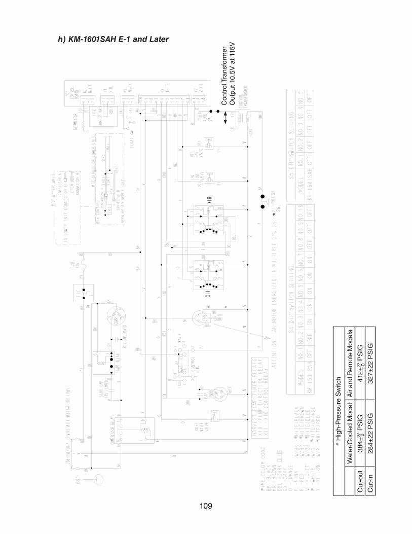
109
h) KM-1601SAH E-1 and Later
*
* H
igh-
Pre
ssur
e S
witc
h
Wat
er-C
oole
d M
odel
Air
and
Rem
ote
Mod
els
Cut
-out
384±
22 P
SIG
412±
22 P
SIG
Cut
-in
284±
22 P
SIG
327±
22 P
SIG
00
Con
trol
Tra
nsfo
rmer
O
utpu
t 10.
5V a
t 115
V

110
i) KM-1301S_H3 T-0, U-0
*
* H
igh-
Pre
ssur
e S
witc
h
Wat
er-C
oole
d M
odel
Air
and
Rem
ote
Mod
els
Cut
-out
384±
22 P
SIG
412±
22 P
SIG
Cut
-in
284±
22 P
SIG
327±
22 P
SIG
00
Con
trol
Tra
nsfo
rmer
O
utpu
t 10.
5V a
t 115
V
Aux
iliar
y C
ode
T-0,
U-0
3 P
hase

111
j) KM-1301S_H3 U-1 to E-0 and KM-1601SAH3 A-0 to E-0
*
* H
igh-
Pre
ssur
e S
witc
h
Wat
er-C
oole
d M
odel
Air
and
Rem
ote
Mod
els
Cut
-out
384±
22 P
SIG
412±
22 P
SIG
Cut
-in
284±
22 P
SIG
327±
22 P
SIG
00
Con
trol
Tra
nsfo
rmer
O
utpu
t 10.
5V a
t 115
V

112
k) KM-1301S_H3 E-1 and KM-1601SAH3 E-1 and Later
* * H
igh-
Pre
ssur
e S
witc
h
Wat
er-C
oole
d M
odel
Air
and
Rem
ote
Mod
els
Cut
-out
384±
22 P
SIG
412±
22 P
SIG
Cut
-in
284±
22 P
SIG
327±
22 P
SIG
00
Con
trol
Tra
nsfo
rmer
O
utpu
t 10.
5V a
t 115
V

113
l) KM-1400SWH3-M
*
* H
igh-
Pre
ssur
e S
witc
h
Wat
er-C
oole
d M
odel
Cut
-out
384±
22 P
SIG
Cut
-in
284±
22 P
SIG
0
Con
trol
Tra
nsfo
rmer
O
utpu
t 10.
5V a
t 115
V


