Download - PROFESSOR: CHARLES KUNG GROUP MEMBERS: AKRAM GERIES, JEEVEN HUGH, MICHAEL LADAS, BRAD LONG
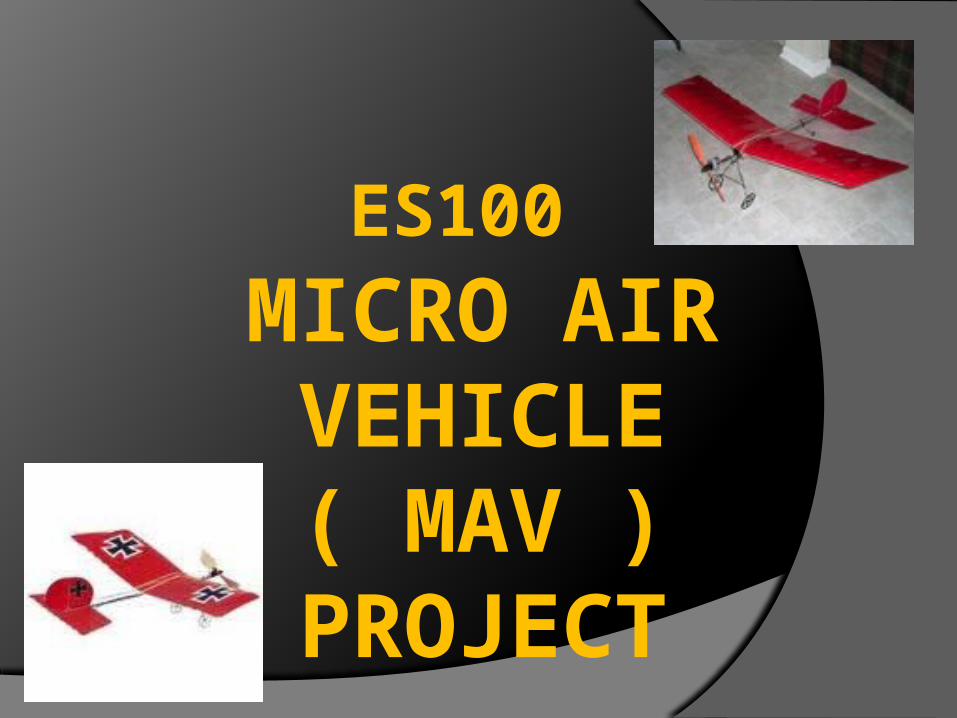
ES100 MICRO AIR VEHICLE ( MAV )
PROJECT

PROFESSOR: CHARLES KUNG
GROUP MEMBERS: AKRAM GERIES, JEEVEN HUGH, MICHAEL LADAS, BRAD LONG

Main Objectives
Fly Slow stick with group-designed camera to satisfy the following criteria:Endurance:○ As many figure 8 paths around two pylons
separated by 30’ in five minutesPrecision Flight:○ Survey an area in all directions and acquire a
legible image of each of the four 1’ x 1’ targets
Gantt Chart
Used to list goals and track progress
Made using an Excel spreadsheet
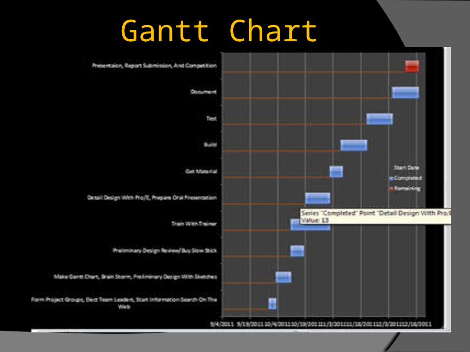
Gantt Chart

Project Specifications The GWS Slow Stick fit our flight
requirements:Has a fixed wing : wingspan of 1176-mm,
length of 954-mm, wing area of 32.64-dm2)Weighs less than 450-g: 450-600 gIs capable of ground takeoff and landingCan fly in a 50’x30’x20’ indoor space with
smooth floorIs recommended for non-experienced flyersDoes not utilize any sort of open flame or
combustion methods of propulsion
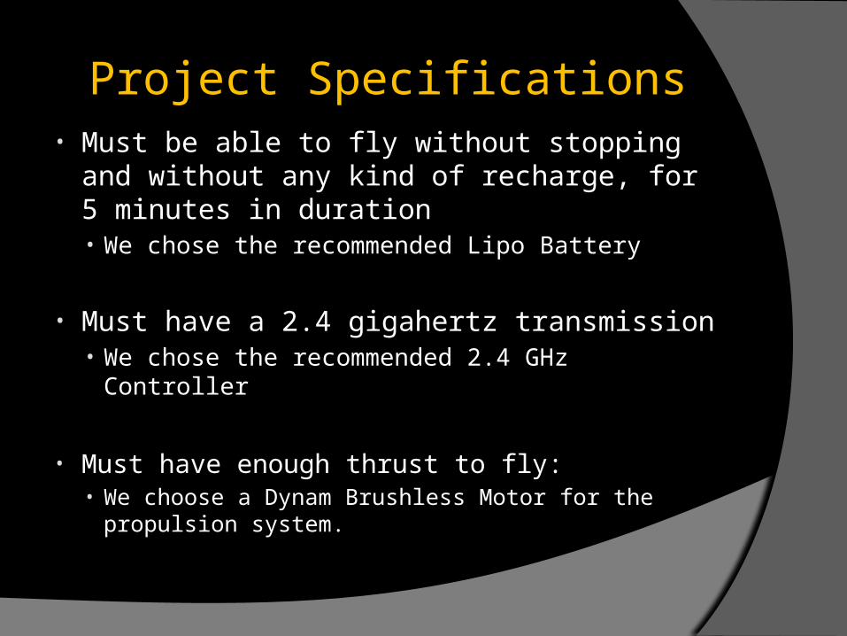
Project Specifications• Must be able to fly without stopping and
without any kind of recharge, for 5 minutes in duration• We chose the recommended Lipo Battery
• Must have a 2.4 gigahertz transmission• We chose the recommended 2.4 GHz Controller
• Must have enough thrust to fly:• We choose a Dynam Brushless Motor for the
propulsion system.
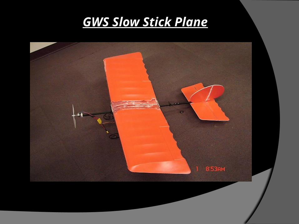
GWS Slow Stick Plane

Slow Stick Model
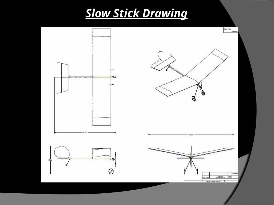
Slow Stick Drawing

Materials List# Quantity Description Material Unit Cost Sub Total1 1 Playmate R/C Airplane Plastic $90 $902 3 AA Duracel Battery, 1.5V Metal $1.25 $3.75
3 1Dynam Brushless Motor+18A 60P-DY-1006 And ESC+3pcs 9g Servos For RC Park Flyer
Metal $24.70 $25
4 1 6-Channel Transmitter/Receiver R6B Metal $32.00 $32.00
5 111.1v 15C LiPoly Battery w/ 3.5 Banana Connector
Metal $7.50 $8
6 1GWS Slow Stick, No Power System - Painted Red
Plastic $28.00 $28.00
Project Budget: < $250 Total: $186
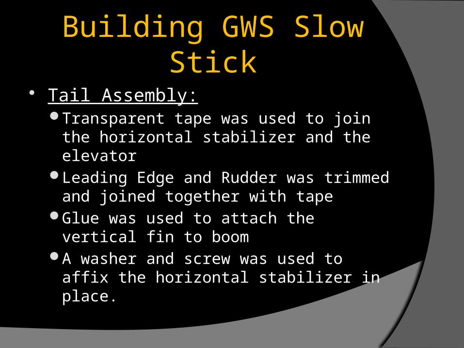
Building GWS Slow Stick
Tail Assembly:Transparent tape was used to join the horizontal
stabilizer and the elevatorLeading Edge and Rudder was trimmed and
joined together with tapeGlue was used to attach the vertical fin to boomA washer and screw was used to affix the
horizontal stabilizer in place.

Tail Assembly

Building GWS Slow Stick
Wing Assembly:A 10 degree dihedral shape was achieved for the
wing using a specialized plastic partThis 10 degree angle was verified by a protractor
Building GWS Slow Stick
Electronic Assembly:The motor and Electronic Speed Control (ESC)
connectors were soldered together using a soldering iron

Soldering Leads Together

Building GWS Slow Stick
Installation of Horn and Linkage and Final Assembly:The horn and linkage were applied and bent into
shape using a pliersA Z Bend was made on the control horn to allow
for field adjustmentThe battery, wing, and other electronics were
fixed to their respective mounts with rubber bands
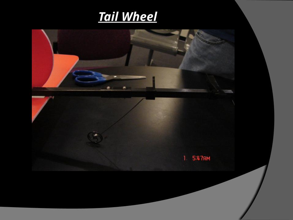
Tail Wheel
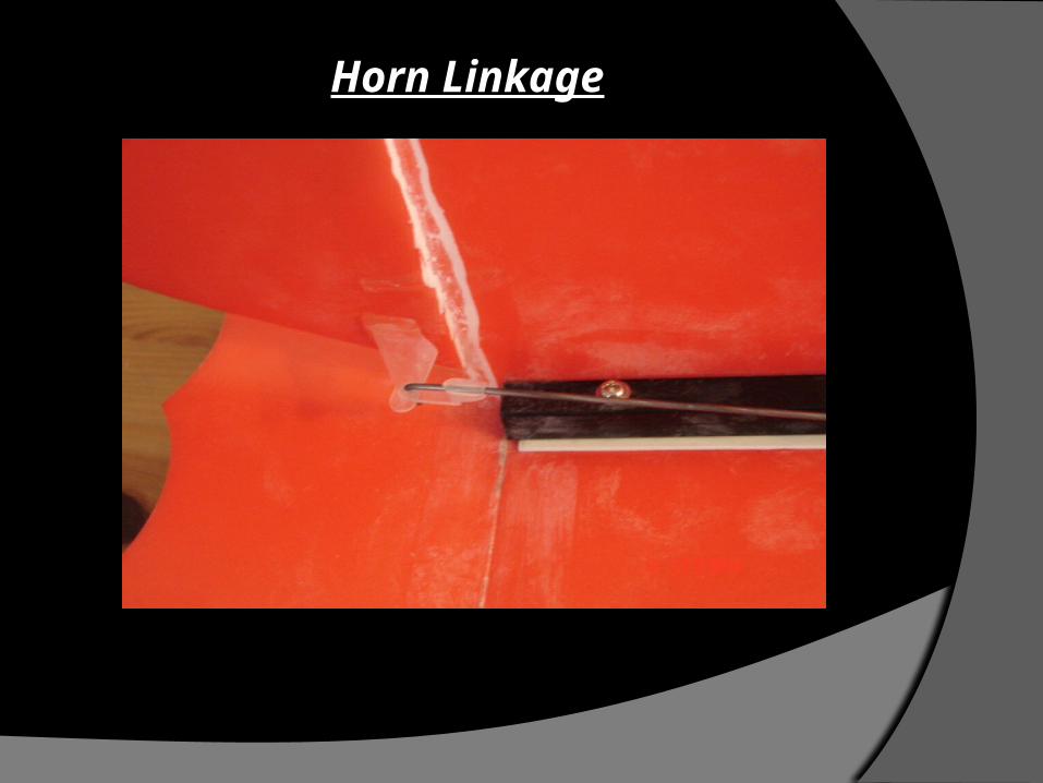
Horn Linkage

Servo
Camera Mount
Specifications for the camera mount:The body-hole must be 1-cm x 1-cm to be able to
mount to the GWS Slow Stick Fuselage.The camera-hole must be 73-mm x 20-mm x 11-
mm to be able to hold the Micro DVR Camera.

Pro-Engineer Drawing
Camera Mount

Camera Mount○ Designing camera mount:
The camera mount was designed so that it had three holes: one to attach to the body of the GWS Slow Stick, the second to make the camera mount lighter so that the GWS Slow Stick would be within the weight requirements, and the third to allow the camera to slide into the holder. The camera mount was initially designed to face forward.
After more analysis, the camera mount was redesigned so that the camera lens would be facing directly downward. This allows the GWS Slow Stick to fly directly over the targets since they are placed face up on the floor.
Camera Mount
Placement of camera mount:To choose where to place the camera mount,
several factors had to be weighed, such as view obstruction, center of gravity, and mobility. After multiple tests, it was determined that the best placement for the camera mount was between the motor and the main gear part because it provided the least view obstruction, the best center of gravity, and the best mobility.

Camera Mount

Balancing The GWS Slow Stick
The Center of Gravity (CG) is normally located at 95-105-mm from the leading edge of the wing at the central wing chord.
Locating CG forward would make the plane more stable, and having the CG a little backward would make it more sensitive when applying throttle.
Two index fingers were placed at the bottom of the wing to find out the location of CG. The airplane is balanced at the point of CG.
The battery pack, the wing, and the mounts can be moved backward or forward to alter the CG.
Binding The Controller The transmitter was found to operate the elevator
backward meaning that when you push up the elevator goes in the wrong direction. The transmitter was also operating the rudder backward meaning that when you push left the rudder goes in the wrong direction.
After downloading the controller software from the internet (http://www.mycoolheli.com/t6config.html), the laptop was connected to the transmitter via a USB cable.
Using the program, channels one and channel two were reversed so that the elevator and rudder were operating in the correct directions.

2.4 G Hz Radio Transmitter

Conclusion
The GWS Slow Stick with the camera mount and a simulated weight was flown successfully.

THE END


