
MODEL CODE SPECIFICATIONS
Model Shown Below: VTD21-22-18-00 with Remote Display
TransmitterRemote Display
Model VTM-025
(sold separately)
Probe 1
Probe 2
Sensor 2
Sensor 1
Sensor 1
Sensor 2
34
Factory
Probe
Cables1
2
SUBMITTAL DRAWINGTHIS DOCUMENT IS SUBJECT
TO CHANGE WITHOUT NOTICE.
THIS DOCUMENT OR THE CONTENTS
THEREOF SHALL NOT BE MODIFIED
WITHOUT PRIOR WRITTEN
PERMISSION BY ACCUTROL LLC.VorTek
G3 Duct Insertion Model VTD
DWG. NO:
REVISION:
SHEET: OF
ECN:
71REV. DATE:
Accutrol Representative: VTD SUBMITTAL
21 Commerce Dr
Danbury, CT 06810
Tel: 203-445-9991
accutrolllc.com
2. One cable is provided with each probe. Contact factory if cables longer than 100' are required.
Cable type is based on the Enclosure Selection per table below.
1. The following information shall be provided with order:NOTES:
3. Maximum length for CPVC and High Temp SS Probe Material is 60".
Device Tag Number
Analog Output Full Scale Range
Analog Output Signal Type
Duct Size
Internal Duct Lining/Insulation Thickness
Enclosure Selection Type of Cable Provided Cable Terminations
0 Plenum Rated Standard RJ45 / Standard RJ45
1 Outdoor Rated Waterproof RJ45 / Standard RJ45
2 Outdoor Rated Waterproof RJ45 / Standard RJ45
3 Outdoor Rated Waterproof RJ45 / Waterproof RJ45
4. When Option D (Internal Transmitter Display) is selected, the Remote Display can not be used.
DUCT SHAPE
1 = Round
2 = Rectangular
3 = Flat Oval
PROBE MATERIAL
1 = Aluminum/ABS
2 = CPVC & ABS
3 = 304SS
4 = High Temp SS (350°F / 177°C Max)
PROBE QUANTITY
1 = 1 Probe
2 = 2 Probes
3 = 3 Probes
4 = 4 Probes
SENSORS PER PROBE
1 = 1 Sensor per Probe
2 = 2 Sensors per Probe
3 = 3 Sensors per Probe
4 = 4 Sensors per Probe
ENCLOSURES
0 = Standard Transmitter, Standard Probe
1 = NEMA 4X Transmitter, Standard Probe
2 = Standard Transmitter, NEMA 4X Probe
3 = NEMA 4X Transmitter, NEMA 4X Probe
4 = Standard Transmitter, NEMA 4X Probe w/Purge
5 = NEMA 4X Transmitter, NEMA 4X Probe w/Purge
CABLE LENGTH (Ref Note 2)
0 = 10' (3.0m)
1 = 25' (7.6m)
2 = 50' (15.2m)
3 = 75' (22.9m)
4 = 100' (30.5m)
VTD - - - -
OPTIONS
BLANK = No Options
B = BACnet MS/TP
D = Internal Transmitter Display (Ref Note 4)
PROBE LENGTH (Ref Note 3)
xx = Inches (04-72)
2378G
5-22-18
EMC AND SAFETY
Emissions
Immunity
Safety
EN 55011:2009+A1:2010, FCC Part 15:2017, ICES-003 Issue 6, EN61000-3-2:2014, EN61000-3-3:2013 EN61326-1:2013, EN61000-4-2:2009, EN61000-4-3:2006+A1:2008+A2:2010 EN61000-4-4:2012, EN61000-4-5:2006, EN61000-4-6:2009, EN61000-4-8:2010 EN61000-4-11:2004 EN61010-1:2010
PERFORMANCE
Accuracy Individual Sensors System Accuracy
Repeatability
+/-2% of reading (factory verified to NIST traceable standard) +/-3% of reading (installed accuracy expected when installation meets or exceeds minimum placement guidelines) +/- 0.1% of reading
Sensor FS Range Factory Default is 3,000 FPM (15.24 m/s) (software configurable)
ENVIRONMENTAL
Operating Temperature Aluminum Probe
CPVC Probe 304SS Probe
304SS High Temp Probe Transmitter
Display (optional) Storage Temperature
Probes and Transmitter Display (optional)
-20° to 140° F (-29° to 60° C) -20° to 140° F (-29° to 60° C) -20° to 200° F (-29° to 93° C) -20° to 320° F (-29° to 160° C) -20° to 150° F (-29° to 66° C) -4° to 158° F (-20° to 70° C) -40° to 150° F (-40° to 66° C) -22° to 176° F (-30° to 80° C)
Humidity Sensors
Transmitter
Non-condensing 0 to 90% non-condensing
ELECTRICAL
Input Power 24VAC +/- 20% 50-60Hz, 2.4 VA with no options, 4.8 VA with display & BACnet options 24VDC +/-10%, 1 W with no options, 3 W with display & BACnet options
Inputs 1 to 4 Probes with up to 4 Sensors per Probe (16 Sensors Max) Output 0-20mA, 4-20mA, 0-10v, 2-10v, 0-5v or 1-5v (software configurable)
12-bit Resolution, Capable of driving 1K ohm load Configuration Port USB 2.0, Isolated, Mini B Connector USB Power Switch Selects alternate power source for configuration when main power is not available
Draws 5v power from USB configuration port Status Indicators LED Status Indicators for; Power, Output, Configuration Port, Power Source Switch, Sensor
Input Channel 3 and 4, Display and BACnet Communications I/O Terminal Block 3 position vertical pluggable screw terminal block, screw access on top, 12-30 AWG
Cables
Plenum rated cables provided with standard enclosures Outdoor rated cables with waterproof plug provided with NEMA 4X enclosures
Network Com Port (Optional)
EIA 485 2-wire BACnet MS/TP Galvanically Isolated Data Rates 9600, 19200, 38400, 57600, 76800 and 115200 1/8 Unit Load Receiver Input Impedance Network bias and EOL Termination not provided within the Transmitter
Display (Optional)
Remote mount or transmitter mount Liquid Crystal Display, 2 lines x 8 characters with white LED backlight Includes USB Configuration Port
MATERIALS OF CONSTRUCTION
Insertion Probes Standard
CPVC 304SS
Aluminum bar, galvanized steel mounting plate, polycarbonate/ABS plastic sensor CPVC plastic bar, 304SS mounting plate, polycarbonate/ABS plastic sensor 304SS bar, 304SS mounting plate, 303SS sensor
Enclosures Standard
Optional
Transmitter: Aluminum Alloy 5052-H32, 16 Gauge Probe Electronics: Galvanized Steel, 18 Gauge Transmitter: NEMA 4X (IP66) Polycarbonate Plastic, V-0 Probe Electronics: NEMA 4X (IPX6) Polycarbonate Plastic, V-0
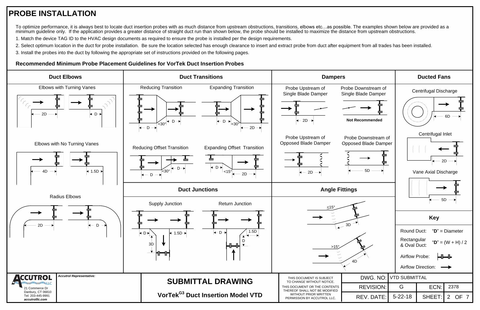
PROBE INSTALLATION
To optimize performance, it is always best to locate duct insertion probes with as much distance from upstream obstructions, transitions, elbows etc…as possible. The examples shown below are provided as a minimum guideline only. If the application provides a greater distance of straight duct run than shown below, the probe should be installed to maximize the distance from upstream obstructions.
1. Match the device TAG ID to the HVAC design documents as required to ensure the probe is installed per the design requirements.
2. Select optimum location in the duct for probe installation. Be sure the location selected has enough clearance to insert and extract probe from duct after equipment from all trades has been installed.
3. Install the probes into the duct by following the appropriate set of instructions provided on the following pages.
Recommended Minimum Probe Placement Guidelines for VorTek Duct Insertion Probes
Centrifugal Discharge
Centrifugal Inlet
Vane Axial Discharge
Supply Junction
Elbows with No Turning Vanes
Elbows with Turning Vanes
Radius Elbows
Reducing Offset Transition
Expanding Transition
Expanding Offset Transition
Ducted FansDuct Elbows Duct Transitions
Reducing Transition
Duct Junctions
Return Junction
3D
1.5DD
6D
2D
5D
4D
>15°
3D
<15°
4D 1.5D
D2D
<30°D
2D<30°
D
D
Probe Upstream of
Single Blade Damper
Probe Downstream of
Single Blade Damper
Probe Upstream of
Opposed Blade DamperProbe Downstream of
Opposed Blade Damper
Dampers
2D Not Recommended
2D 5D
Angle Fittings
Airflow Direction:
Airflow Probe:
“D” = (W + H) / 2
Round Duct:
Rectangular
& Oval Duct:
Key
“D” = Diameter
<30°D
D
2D<15°
D
D
1.5DD
SUBMITTAL DRAWINGTHIS DOCUMENT IS SUBJECT
TO CHANGE WITHOUT NOTICE.
THIS DOCUMENT OR THE CONTENTS
THEREOF SHALL NOT BE MODIFIED
WITHOUT PRIOR WRITTEN
PERMISSION BY ACCUTROL LLC.VorTek
G3 Duct Insertion Model VTD
DWG. NO:
REVISION:
SHEET: OF
ECN:
72REV. DATE:
Accutrol Representative: VTD SUBMITTAL
D2D
21 Commerce Dr
Danbury, CT 06810
Tel: 203-445-9991
accutrolllc.com
2378G
5-22-18

1 X 2 2 X 2
Each probe will require either one or two holes to be drilled into the duct for installation. Probes 13" and less require only one hole which is referred to as the Insertion Hole. Probes 14" and greater include a
threaded stud at the probe end which requires an additional hole referred to as the Receiving Hole. Reference Table 1 to determine the hole drilling requirements for your application. Reference Table 2 for the
recommended probe/sensor density based on the duct size. For ducts with internal lining or insulation, the probes provided have been manufactured to accommodate the insulation thickness.
PROBE INSTALLATION - Round Duct Applications
3 X 41 X 1
WARNING: Use eye protection, cut-resistant gloves and clothing suitable for working with sheet metal.
Failure to do so may result in personal injury.
1. Mark the duct where the center of the Probe 1 Insertion Hole is to be located.
5. For applications with three probes, each probe shall be located 60 degrees from the next with a 4" offset.
Mark the duct where the center of the Probe 2 Insertion Hole is to be located and repeat steps 2 and 3.
Mark the duct where the center of the Probe 3 Insertion Hole is to be located and repeat steps 2 and 3.
6. Drill the required holes (Reference Table 1) and install each probe with the threaded stud extending through the Receiving Hole.
7. Position each probe so the Airflow Direction Arrow is aligned with the airflow direction in the duct.
8. Secure the mounting plate of each Probe using #10 Tek-Screws. For probes 14" and longer, secure the threaded stud using the locknuts provided.
4. For applications with two probes, Probe 2 shall be located 90 degrees from Probe 1 with a 4" offset.
Mark the duct where the center of the Probe 2 Insertion Hole is to be located and repeat steps 2 and 3.
2. Measure the circumference of the duct and mark a straight line extending from the center of the Insertion Hole around the circumference of the duct.
3. Locate and mark the center of the Receiving Hole by measuring ½ the Circumference of the duct from the center of the Insertion Hole.
SUBMITTAL DRAWINGTHIS DOCUMENT IS SUBJECT
TO CHANGE WITHOUT NOTICE.
THIS DOCUMENT OR THE CONTENTS
THEREOF SHALL NOT BE MODIFIED
WITHOUT PRIOR WRITTEN
PERMISSION BY ACCUTROL LLC.VorTek
G3 Duct Insertion Model VTD
DWG. NO:
REVISION:
SHEET: OF
ECN:
73REV. DATE:
Accutrol Representative: VTD SUBMITTAL
Receiving Hole
Slot in Stud to be Aligned With Airflow
90°
Insertion Hole
4"
AIRFLOW
Duct Diameter Probe Configuration(probe qty X sensors/probe)
3 to 6
8 to 12
14 to 28
Table 2
30 to 52
54 to 72
76 to 152
203 to 305
356 to 711
762 to 1321
1372 to 1829
inches millimeters
1 X 1
1 X 2
2 X 2
2 X 4
3 X 4
4. Position Probe per Airflow Direction Arrow.
1. Mark the duct where probe is to be inserted.
2. Drill the Insertion Hole per Table 1.
3. Insert Probe into Hole.
5. Secure Probe to Duct by installing #10 Tek-
Screws into the mounting plate holes.60°
60°
4" 4"
AIRFLOW
AIRFLOW
Table 1
Probe Length
3 to 6
7 to 13
> 14
76 to 152
178 to 330
> 356
inches mm
Insertion Hole
Diameter
2.5
3.5
3.5
64
90
90
inches mm
Receiving
Hole Diameter
.312
Not Required
8
inches mm
Not Required
2. Tek-Screws provided by others.
NOTES:
1. Be sure the location selected has enough clearance
to insert and extract probe from duct after equipment
from all trades has been installed.
21 Commerce Dr
Danbury, CT 06810
Tel: 203-445-9991
accutrolllc.com
2378G
5-22-18

Each probe will require either one or two holes to be drilled into the duct for installation. Probes 13" and less require only one hole which is referred to as the Insertion Hole. Probes 14" and greater include a threaded
stud at the opposite end which requires an additional hole referred to as the Receiving Hole. Reference Table 1 to determine the hole size requirements for your application.
PROBE INSTALLATION - Rectangular Duct Applications
Before proceeding, confirm the probes provided are correct for the application (Reference Figure 1 & Table 2). The Insertion Side of the duct “H” is where the probes are to be installed and the other side of the duct
“W” should be the same as the probe length for probes >14". For ducts with internal lining or insulation, the probes provided have been manufactured to accommodate the insulation thickness.
WARNING: Use eye protection, cut-resistant gloves and clothing suitable for working with sheet metal.
Failure to do so may result in personal injury.
Figure 3
SUBMITTAL DRAWINGTHIS DOCUMENT IS SUBJECT
TO CHANGE WITHOUT NOTICE.
THIS DOCUMENT OR THE CONTENTS
THEREOF SHALL NOT BE MODIFIED
WITHOUT PRIOR WRITTEN
PERMISSION BY ACCUTROL LLC.
DWG. NO:
REVISION:
SHEET: OF
ECN:
74REV. DATE:
Accutrol Representative: VTD SUBMITTAL
Figure 2
A2
A1
A3
A4
Ins
ert
ion
Sid
e
Re
ce
ivin
g S
ide
Slot in Stud to be Aligned With Airflow
AIRFLOW
AIRFLOW
AIRFLOW
AIRFLOW
Ins
ert
ion
Sid
e
Receiving Hole
Insertion Hole
4. Drill the required holes in the positions marked. Reference Table 1 for the hole sizes.
5. Install each probe through the insertion hole until the threaded stud extends through the Receiving Hole.
6. Position each probe so the Airflow Direction Arrow is aligned with the airflow direction in the duct.
7. Secure the mounting plate of each Probe to the duct using #10 Tek-Screws.
For probes 14" and longer, secure the threaded stud on the Receiving Side using the locknuts provided.
1. Identify the Insertion Side of the duct and draw a straight line perpendicular to the edges of the duct extending edge-to-edge per Figure 2.
2. Mark the center of each Insertion Hole location A1-A4 per Figure 2.
3. Repeat the above steps on the opposite side of the duct to mark the corresponding Receiving Holes.
The duct hole locations A1-A4 are based on the quantity of probes and the size of the duct “H” on the insertion side.
To determine A1-A4 for the application, reference the device schedule and probe tag. Single probe applications require A1 only, 2-probe applications require A1 & A3, 3-probe applications require A1, A2 & A3 and 4-probe applications require A1, A2, A3 and A4.
Table 1
Probe Length
3 to 6
7 to 13
> 14
76 to 152
178 to 330
> 356
inches mm
Insertion Hole
Diameter
2.5
3.5
3.5
64
90
90
inches mm
Receiving
Hole Diameter
.312
Not Required
8
inches mm
Not Required
2. Tek-Screws provided by others.
1. Be sure the location selected has enough clearance to insert and
extract probe from duct after equipment from all trades has been
installed.
NOTES:
3. For 2-Probe applications with duct “H” between 12 and 16", the 2
probes are factory-mounted onto a single plate.
Figure 1
H
Re
ce
ivin
g S
ide
Ins
ert
ion
Sid
e
W
Table 2
4 6 8 9,10 11,12 13-18 19-24 25-30 31-36 37-42 43-48 49-54 55-60 61-66 67-72
4 1x1 1x1 1x1 1x1
6 1x1 1x1 1x1 1x2 1x2 1x2 1x2 1x3 1x3 1x3 1x4 1x4
8 1x1 1x1 1x2 1x2 1x2 1x2 1x2 1x3 1x3 1x3 1x4 1x4 1x4 1x4 1x4
9,10 1x1 1x1 1x2 1x2 1x2 1x2 1x2 1x3 1x3 1x3 1x4 1x4 1x4 1x4 1x4
11,12 2x1 2x1 2x1 1x2 2x2 2x2 2x3 2x3 2x3 2x3 2.x3 2x3 2.x3 2x4
13-18 2x1 2x1 2x1 2x2 2x2 2x2 2x3 2x3 2x3 2x3 2x4 2x4 2x4 2x4
19-24 2x1 2x1 2x1 2x2 2x2 2x3 2x3 2x3 2x3 2x4 2x4 2x4 2x4 2x4
25-30 3x1 3x1 3x1 3x2 3x2 3x2 3x3 3x3 3x3 3x4 3x4 3x4 3x4 3x4
31-36 3x1 3x1 3x1 3x2 3x2 3x2 3x3 3x3 3x3 3x4 3x4 3x4 4x4 4x4
37-42 3x1 3x1 3x1 3x2 3x2 3x2 3x3 3x3 3x3 3x4 3x4 4x4 4x4 4x4
43-48 4x1 4x1 4x1 3x2 3x2 4x2 4x3 4x3 4x3 4x4 4x4 4x4 4x4 4x4
49-54 4x1 4x1 4x1 4x2 4x2 4x2 4x3 4x3 4x3 4x4 4x4 4x4 4x4 4x4
55-60 4x1 4x1 4x1 4x2 4x2 4x2 4x3 4x3 4x4 4x4 4x4 4x4 4x4 4x4
61-66 4x1 4x1 4x1 4x2 4x2 4x3 4x3 4x4 4x4 4x4 4x4 4x4 4x4 4x4
67-72 4x1 4x1 4x1 4x2 4x2 4x3 4x3 4x4 4x4 4x4 4x4 4x4 4x4 4x4
Inches
Duct Width (W) (Bar Length)
Insert
ion
Sid
e o
f D
uct
(H)
VorTekG3
Duct Insertion Model VTD
21 Commerce Dr
Danbury, CT 06810
Tel: 203-445-9991
accutrolllc.com
2378G
5-22-18

Each probe will require either one or two holes to be drilled into the duct for installation. Probes 13" and less require only one hole which is referred to as the Insertion Hole. Probes 14" and greater include a threaded
stud at the opposite end which requires an additional hole referred to as the Receiving Hole. Reference Table 1 to determine the hole size requirements for your application.
PROBE INSTALLATION – Flat Oval Duct Applications
Reference Figure 1: Before proceeding, confirm the probes provided are correct for the application. The Insertion Side is where the probes are to be installed over the flat “F” area. The “D” dimension should be the
same as the probe length for probes >14". For ducts with internal lining or insulation, the probes provided have been manufactured to accommodate the insulation thickness.
WARNING: Use eye protection, cut-resistant gloves and clothing suitable for working with sheet metal.
Failure to do so may result in personal injury.
A2A1
A3
Insertion Side
Receiving Side
A4
Figure 2
4. Drill the required holes in the positions marked. Reference Table 1 for the hole sizes.
5. Install each probe through the insertion hole until the threaded stud extends through the Receiving Hole.
6. Position each probe so the Airflow Direction Arrow is aligned with the airflow direction of the duct.
7. Secure the mounting plate of each Probe to the duct using #10 Tek-Screws. For probes 14" and longer, secure the threaded stud using the locknuts provided.
1. Identify the Insertion Side of the duct and draw a straight line perpendicular to the edges of the duct extending edge-to-edge per Figure 2.
The duct hole locations A1-A4 are based on the quantity of probes and the Major Duct Dimension “M” on the insertion side.
2. Mark the center of each Insertion Hole location A1-A4 per Figure 2.
3. Repeat the above steps on the opposite side of the duct to mark the corresponding Receiving Holes.
To determine A1-A4 for the application, reference the device schedule and probe tag. Single probe applications require A1 only, 2-probe applications require A1 & A3, 3-probe applications require A1, A2 & A3 and 4-probe applications require A1, A2, A3 and A4.
2. Tek-Screws provided by others.
NOTES:
SUBMITTAL DRAWINGTHIS DOCUMENT IS SUBJECT
TO CHANGE WITHOUT NOTICE.
THIS DOCUMENT OR THE CONTENTS
THEREOF SHALL NOT BE MODIFIED
WITHOUT PRIOR WRITTEN
PERMISSION BY ACCUTROL LLC.VorTek
G3 Duct Insertion Model VTD
DWG. NO:
REVISION:
SHEET: OF:
ECN:
75REV. DATE:
Accutrol Representative: VTD SUBMITTAL
1. Be sure the location selected has enough clearance to insert and extract probe from duct after equipment from all trades has been installed.
Figure 1
M = Major Dimension
D = Minor Dimension
F = Flat = M-D
Insertion S
ide
Receiving Side
M
D
F
Slot in Stud to be Aligned With Airflow
Receiving Side
Figure 3
Insertion Side
AIR
FL
OW
AIR
FL
OW
AIR
FL
OW
AIR
FL
OW
Table 1
Probe Length
3 to 6
7 to 13
> 14
76 to 152
178 to 330
> 356
inches mm
Insertion Hole
Diameter
2.5
3.5
3.5
64
90
90
inches mm
Receiving
Hole Diameter
.312
Not Required
8
inches mm
Not Required
21 Commerce Dr
Danbury, CT 06810
Tel: 203-445-9991
accutrolllc.com
2378G
5-22-18

TRANSMITTER INSTALLATION
2. Using the four 0.20" diameter holes located on the transmitter enclosure, secure the transmitter to mounting surface using (4) #8 or #10 Pan Head Screws. For sheet metal mounting surface, use sheet metal or tek screws, for plywood surface use coarse thread wood screws, for drywall surface, use drywall anchors with the appropriate screws.
1. Loosen the thumb screw located on the transmitter enclosure cover and remove cover.
2. Run 3-conductor cable from the field controller to the transmitter through the strain relief fitting.
3. Remove the terminal block from the power/signal header, loosen the three screws and terminate the power, common and output signal wires in the terminal block per markings.
4. Tighten the terminal block screws, verify wires are secure and reconnect to the header.
5. If BACnet is required; run BACnet MS/TP cable into enclosure, remove terminal block from BACnet header and terminate the BACnet wires in the appropriate terminals. Tighten the terminal block screws, verify wires are secure and reconnect to header.
6. If Remote Display is required; remove knock-out located directly in line with the Display Port, install strain relief fitting into .875" dia. hole, run the factory cable provided with the Remote Display into the enclosure and plug cable into the Display Input Port.
7. The Channel 3-4 input board is required for applications that have 3 and 4 probes. Applications with 1 or 2 probes do not require this board.
1. Select an easily accessible location to install the transmitter within the range of the Probe Cables that have been provided by the factory. Provide clearance to remove the cover
and easily access the connectors and field connections.
3. Connect each probe to the corresponding probe input channel on the transmitter using the cables provided (Reference Figure 1)
SUBMITTAL DRAWINGTHIS DOCUMENT IS SUBJECT
TO CHANGE WITHOUT NOTICE.
THIS DOCUMENT OR THE CONTENTS
THEREOF SHALL NOT BE MODIFIED
WITHOUT PRIOR WRITTEN
PERMISSION BY ACCUTROL LLC.VorTek
G3 Duct Insertion Model VTD
DWG. NO:
REVISION:
SHEET: OF
ECN:
76REV. DATE:
Accutrol Representative: VTD SUBMITTAL
TRANSMITTER WIRING
CAUTION: Do not use
transmitter enclosure as a
junction box. Only wires
terminating on the
transmitter board should
enter the enclosure.
AIRFLOW
AIRFLOW
AIRFLOW
AIRFLOW
Figure 1
Probe Cables
1234
Duct
Probe
1 of 4
Probe
2 of 4
Probe
3 of 4
Probe
4 of 4
NOTE
Captive cable ties provided on the Transmitter
and Probe Electronics Enclosures are to be
used for probe cable strain relief.
Figure 3
Probe 1 Input
Removable
Terminal Plug(Power, Com, Output)
Power Source Switch
USB Config. Port
BACnet MS/TP Port
(Optional)
Probe 2 Input
Probe 3 Input
Probe 4 Input
BAS Controller
Remote Display Port
(For Optional Display)
Ref Note 7Ch. 3,4 Input Board
Strain Relief
for Probe
Cables
Figure 2
Strain Relief Fitting
.875" dia. knock-out
provided for BACnet
6.37"
(162mm)
Ø 0.2" (5mm)
(4 places)
5.97"
(152mm)
5.62"
(143mm)
4.64"
(118mm)
2.12"
(54mm)
12
34
Probe Cable
Connectors
.875" dia. knock-out
provided for Remote
Display Cable
Cover
Thumb
Screw
Strain Relief for
Probe Cables
21 Commerce Dr
Danbury, CT 06810
Tel: 203-445-9991
accutrolllc.com
24 vAC
-
+
CAUTION: Polarity must be maintained if 24v
power source is used to power more than one
device otherwise equipment may be damaged.
The power source must include a circuit
breaker and be current limited to 8 amps
maximum and grounded on the (-) side.
ANALOG
INPUT
2378G
5-22-18
THIS DOCUMENT IS SUBJECT
TO CHANGE WITHOUT NOTICE.
THIS DOCUMENT OR THE CONTENTS
THEREOF SHALL NOT BE MODIFIED
WITHOUT PRIOR WRITTEN
PERMISSION BY ACCUTROL LLC.
DWG. NO:
REVISION:
SHEET:
ECN:
REV. DATE:
Accutrol Representative:
21 Commerce Dr
Danbury, CT 06810
Tel: 203-445-9991
accutrolllc.com
3.10 in
79 mm
PROBE CABLE
CONNECTORS
INTERNAL
DISPLAY
5.62 in
143 mm
5.97 in
152 mm6.37 in
162mm
4.65 in
118 mm
POWER/SIGNAL
CABLE ENTRY
`
4 3 2 1
EXTERNAL
DISPLAY CONNECTOR
(NOT PROVIDED WITH
OPTIONAL INTERNAL
DISPLAY)
INTERNAL
DISPLAY
(OPTIONAL)
11.35 in
288 mm
7.50 in
190 mm8.58 in
218mm
9.17 in
233 mm
5.60 in
142 mm 5.91 in
150 mm
BACNET
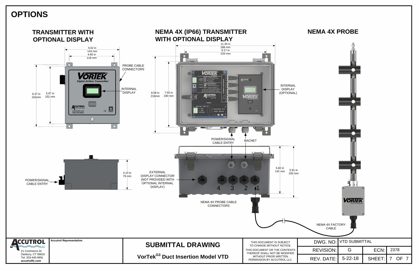
OPTIONS
TRANSMITTER WITH
OPTIONAL DISPLAY
AIRFLOW SENSOR
NEMA 4X FACTORY
CABLE
NEMA 4X PROBE
NEMA 4X PROBE CABLE
CONNECTORS
POWER/SIGNAL
CABLE ENTRY
SUBMITTAL DRAWING
VorTekG3
Duct Insertion Model VTD OF 77
VTD SUBMITTAL
NEMA 4X (IP66) TRANSMITTER
WITH OPTIONAL DISPLAY
2378G
5-22-18


