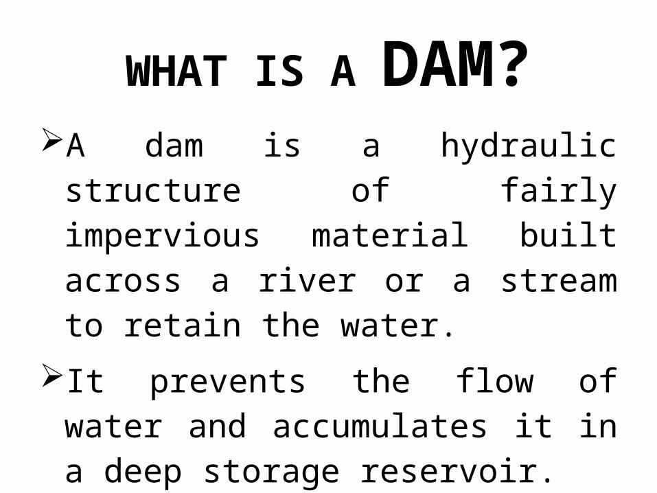
WHAT IS A DAM?A dam is a hydraulic structure of fairly
impervious material built across a river or a stream to retain the water.
It prevents the flow of water and accumulates it in a deep storage reservoir.

PURPOSE OF DAMIrrigation Power generation Water supply Flood control Navigation Recreation

STRUCTURE OF DAM
Heel
Gallery
Toe
Spillway(inside dam)
Crest
NWL (Normal water level)
MWL (Max. water level)
Free board
Sluice way
Upstream Down stream
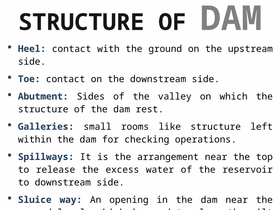
Heel: contact with the ground on the upstream side.
Toe: contact on the downstream side.
Abutment: Sides of the valley on which the structure of the dam rest.
Galleries: small rooms like structure left within the dam for checking operations.
Spillways: It is the arrangement near the top to release the excess water of the reservoir to downstream side.
Sluice way: An opening in the dam near the ground level, which is used to clear the silt accumulation in the reservoir side.
STRUCTURE OF DAM

CLASSIFICATION OF
DAMS
• Based on dam function1• Based on material construction2• Based on hydraulic behavior3• Based on structural behavior4
Dams are classified according to several considerations as indicated below.

• BASED ON DAM FUNCTION1
Coffer dams: A coffer dam is a temporary dam constructed to divert water for facilitating construction.
Storage dams: They are constructed to store water during the rainy season when there is a large flow in the river. Water is stored for later use in dry season.
Diversion dams: A diversion dam is constructed for the purpose of diverting water of the river into an off-taking canal (or a conduit).
Detention dams: A detention dam retards the flow in the river on its downstream during floods by storing some flood water.
Debris dams: A debris dam is constructed to retain debris such as sand, gravel, and drift wood flowing in the river with water.

• BASED ON MATERIAL CONSTRUCTION2
Rigid Dam: It is constructed with rigid material such as stone, masonry, concrete, steel, or timber. Steel dams and timber dams are constructed only for small heights.Non-rigid Dam: It is constructed with non-rigid material such as earth, tailings, rockfill etc.
Earthen dam – gravel, sand, silt, clay etc.
Tailings dam – waste or refuse obtained from mines
Rockfill dam – rock material supporting a water tight material on the u/s face.

Overflow Dam: It is constructed with a crest to permit overflow of surplus water that cannot be retained in the reservoir. (e.g. Nolichucky Dam USA)
Non-Overflow Dam: It is constructed such that water is not allowed to overflow over its crest.
(e.g. Kurobe Dam JAPAN)
• BASED ON HYDRAULIC BEHAVIOR3

• BASED ON STRUCTURAL BEHAVIOR4
EMBANKMENT DAM GRAVITY DAM
BUTTRESS DAM
ARCH DAM

EMBANKMENT DAM
It is a non-rigid dam which resists the forces acting on it by its shear strength and upto some extent by its own weight
Earth dams are constructed where the foundation or the underlying material are weak to support the masonry dam.
They are trapezoidal in shape and mainly built with clay, sand and gravel, hence they are also known as Earth fill dam or Rock fill dam.


It is a masonry or concrete dam which resists the forces acting on it by its own weight.
These dams are heavy and massive wall-like structures of concrete in which the whole weight acts vertically downwards. Its c/s is approximately triangular in shape.
As the entire load is transmitted on the small area of foundation, such dams are constructed where rocks are competent and stable.
GRAVITY DAM

It is a masonry or concrete dam which resists the forces acting on it by series of structural supports called buttresses.
Buttresses transmit force from wall of dam to wider area of ground. These buttresses are in the form of triangular or multiple arch masonry or reinforced concrete walls.
This type of structure can be considered even if the foundation rocks are little weaker.
BUTTRESS DAM

It is a curved masonry or concrete dam, convex upstream, which resists the forces acting on it by arch action.
Arch dams are built across narrow and deep river, this shape helps to transmit the major part of the water load to the abutments. So this shape requires strong abutments.
Arch dams are cheaper dams, because they give good strength with less material required.
ARCH DAM

Gravity dams are rigid concrete dams which ensure stability against all loads by virtue of their weight alone. They transfer all the loads to the foundation and hence are built when the foundation is strong rock. A typical section of a gravity dam is shown.
GRAVITY DAMS

Following are forces acting on Gravity Dam
1) Water Pressure
2) Weight of the Dam
3) Uplift Pressure
4) Silt Pressure
5) Wave Pressure
6) Ice Pressure
7) Earthquake Pressure

1) Water Pressure
It is the major external force acting on a dam.
The water pressure on the upstream face depends on the water surface level in the reservoir and acts horizontally. In case the dam has a batter in the upstream side, the load of water over the batter is also present and acts vertically.

1) Water Pressure The horizontal water pressure acts at a height of H/3
from base of the dam, and is given by
The vertical water pressure acts on the length ‘b’ portion of the base. This vertical pressure is given by

Similarly, the water pressure on the downstream face is due to the tail water and acts horizontally while the weight of water on the downstream face acts vertically.
1) Water Pressure

2) Weight of the Dam Weight of the dam is the major resisting force.
Total weight of the dam acts at the center of gravity of its section. Unit length of the dam is considered in the calculation of weight.
W = W1 + W2 + W3

3) Uplift Pressure
Uplift pressure is the pressure exerted by water as it seeps through the body of the dam or its foundation.
Seeping water exerts pressure on the base of the dam and it depends upon water head.
Uplift pressure is given by

4) Silt Pressure
Sediment deposition in the reservoir results in a force acting horizontally on the upstream face. This force is assumed to have a hydrostatic distribution.
Silt Pressure is given by acting at H/3 from base.

5) Wave Pressure Waves are generated on the surface of the
reservoir by the blowing winds, which exert a pressure on the upstream side. Wave pressure depends upon wave height, and is given by the equation acting at above the reservoir surface.

6) Ice Pressure The ice which may be formed on the water
surface of the reservoir in cold countries may sometimes melt and expand. The dam face is subjected to the thrust exerted by the expanding ice.
Earthquakes impart a horizontal as well as a vertical acceleration to the dam and the stored water. This results in additional forces, both in the horizontal and vertical directions. Horizontal and vertical “seismic coefficients” are used to appropriately modify these forces to account for the effect of earthquakes.
7) Earthquake Pressure

FAILURE MODES OF
GRAVITY DAMS
1) Overturning
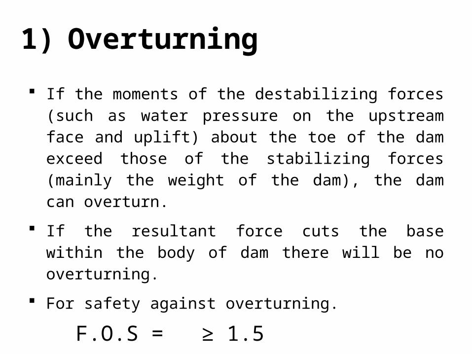
If the moments of the destabilizing forces (such as water pressure on the upstream face and uplift) about the toe of the dam exceed those of the stabilizing forces (mainly the weight of the dam), the dam can overturn.
If the resultant force cuts the base within the body of dam there will be no overturning.
For safety against overturning.
F.O.S = ≥ 1.5

2) Sliding
A gravity dam may fail in sliding at any horizontal plane if the sum of the actuating horizontal forces above that plane is less than the resistive forces.
For safety against sliding F.O.S = µ × > 1
Where µ = coefficient of static earth pressure = 0.65 to 0.75

3) Normal Stress In order to calculate the normal stress distribution
at the base, or at any section, let be the total horizontal force, be the total vertical force and R be the resultant force cutting the base at an eccentricity e from the center of the base of width (b), which is equal to b/2 − x where x is the distance of the resultant force R from the toe given by
3) Normal Stress
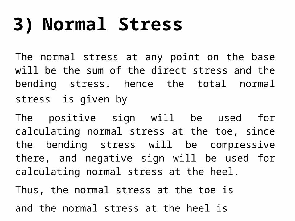
The normal stress at any point on the base will be the sum of the direct stress and the bending stress.
hence the total normal stress is given by
The positive sign will be used for calculating normal stress at the toe, since the bending stress will be compressive there, and negative sign will be used for calculating normal stress at the heel.
Thus, the normal stress at the toe is
and the normal stress at the heel is

Normal Stress Distribution Under The Base Of Dam

Principal stresses The principal stresses are given as At the toe of the dam is
σ = sec² β
At the heel of the dam isσ = sec² α – tan² α
Where
= normal stress
= wh = intensity of water pressure

Shear stresses The shear stresses are given as At the toe of the dam
τ = tan β
At the heel of the damτ = - (- ) tan α
Where = normal stress = wh = intensity of water pressure

FLOW CHART
FOR THE ANALYSIS OF GRAVITY DAMS

1) Consider unit length of the dam.
2) Calculate the vertical forces:
Weight of the dam,
Weight of water acting on inclined faces,
Uplift force.
find sum of these vertical forces ()
FLOW CHART

FLOW CHART 3) Find out the sum of horizontal forces:
Horizontal component of the water pressure is
P = w h² / 2
Find water pressure on both U/S and D/S side
Find moment due to various forces at the toe

FLOW CHART 4) Calculate
Disturbing moments (taken as -ive)
and
Resisting moments (taken as +ive)
And also find their algebraic sum
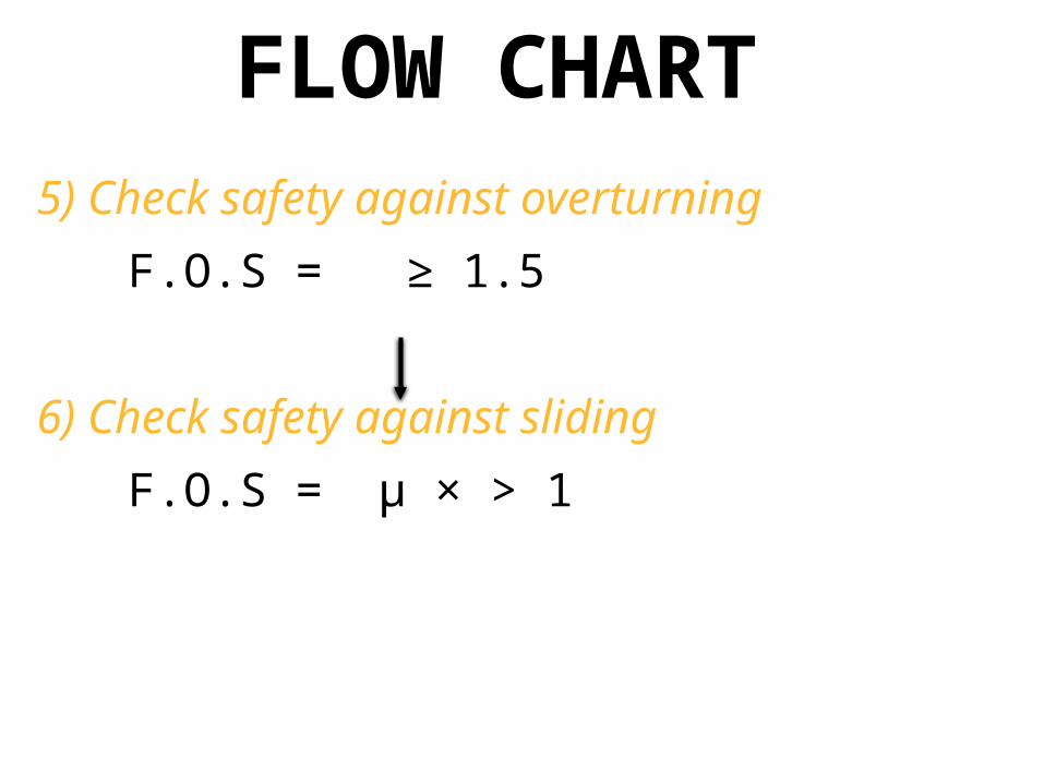
FLOW CHART 5) Check safety against overturning
F.O.S = ≥ 1.5
6) Check safety against sliding
F.O.S = µ × > 1

FLOW CHART 7) Calculate the shear friction factor.
In large dams, shear strength of joint should also be considered. Factor of safety in that case is known as shear friction factor.
S.F.F =
b = width of the joint
q = shear strength of the joint (14 kg/cm³)

FLOW CHART 8) Find out the location (i.e. distance x)
of resultant force from the toe.
9) Find out eccentricity e of the resultant from the center.
e = b/2 – x
where b = base width of the dam

FLOW CHART 10) Find the normal stress at the toe.
(compressive stress is taken as positive)
11) Find the normal stress at the heel.
(tensile stress is taken as negative)

FLOW CHART 12) Find out principal stress at the toe
σ = sec² β
13) Find out principal stress at the heel
σ = sec² α – tan² α
Where
= normal stress
= wh = intensity of water pressure

FLOW CHART 14) Find out shear stress at toe.
τ = tan β
15) Find out shear stress at the heel
τ = - (- ) tan α
Where
= normal stress
= wh = intensity of water pressure

Question # 01: A masonry dam 10m high is trapezoidal section with a top width of 1m and a bottom width of 8.25m. The face exposed to the water has a batter of 1:10. Test the stability of the dam. Find out the principal stresses at the toe and heel of the dam. Assume unit weight of masonry as 2240 Kg/m³, w for water = 1000 Kg/m³ and permissible shear stress of joint = 14 Kg/cm³.
EXAMPLE


SOLUTION1) Consider unit length of
the dam i.e. 1m
2) Vertical forces:
a) self weight of the dam
WD = [(½ × 1 × 10) + (½× 6.25 × 10) + (1× 10)] ×1× 2240
= 103600 kg

b) weight of water in column AA’B
WW = (½×1×10) × 1 ×1000
= 5000 kg
c) Uplift pressure
WU=(½×8.25×10)×1×1000
= 41250 kg
= 103600+5000–41250
= 67350 kg

3) Horizontal water pressure
∑H = wh²/2 = 1000 × 100 / 2
= 50,000 kg

a) Due to self weight of the dam
= {( ½ ×1×10×2240) (1+6.25+1/3)} +
{( 1×10×2240) (6.25+0.5)}
+
{( ½×6.25×10×2240) (2/3×6.25)}
= 527800 kg-m (+ ive)
Moment due to various forces at the toe

b) Due to column of water in AA’B
= (½×10×1×1000)
(8.25 – 1/3)
= 39583 kg-m (+ive)
c) Due to uplift force
=(½×8.25×10×1000)
(2/3×8.25)
= 226875 kg-m (-ive)
Moment due to various forces at the toe

d) Due to horizontal water pressure
=1000 × 100/2 × 10/3
= 166,700 kg-m (-ive)
Moment due to various forces at the toe
∑M = 527800 + 39583 – 226875 – 166700
= 567383 – 339575
= 227808 kg-m

5) Check safety against overturning
F.O.S = =
≥ 1.5 ………(O.K)
6) Check safety against sliding
F.O.S = µ ×
= 1.01 > 1 ………(O.K)

7) Shear friction factor
S.F.F = =
= 24.11
8) The resultant acts at a distance x
from toe
= = 3.38
9) Eccentricity e from the center is
e = b/2 – x = 8.25/2 – 3.38 = 0.74

10) Compressive stress at the toe
= 67350/8.25 {1 + (6×0.74)/8.25} = 12560 kg/m²
11) Compressive stress at the heel
= 67350/8.25 {1 - (6×0.74)/8.25} = 3770 kg/m²

12) principle stress at the toe
σ = sec² β
sec β =1/(10/11.792)
=1.179
σ = sec² β
= 12560×(1.39)
= 17460 kg/m²
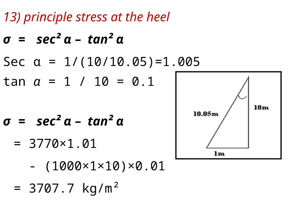
13) principle stress at the heel
σ = sec² α – tan² α
Sec α = 1/(10/10.05)=1.005
tan α = 1 / 10 = 0.1
σ = sec² α – tan² α
= 3770×1.01
- (1000×1×10)×0.01
= 3707.7 kg/m²

14) shear stress at the toe
τ = tan β
tan β = 6.25 / 10 = 0.625 τ = tan β
= 12560 × 0.625 = 7850 kg/m²15) shear stress at the heel
τ = - (- ) tan α
tan α = 1 / 10 = 0.1
τ = - (- ) tan α
= -(3770-1000×10)×0.1 = 623 kg/m²


