download pump inverter manual here
TRANSCRIPT
www.electrilabs.co.za
Solar Pumping Inverter
Operation Manual
Infinite Solar Energy

I
Preface
Thank you very much for using the PB series of solar pumping inverter.
Please be sure to read this manual carefully before installation and use in order to give
full play to the performance of this product and ensure the safety of user and
equipment.
Please preserve the manual in an orderly manner in order to subsequently facilitate the
routine inspection and maintenance of the inverter and find out the cause of abnormity
and treatment countermeasure.
If there are any puzzling questions or specific requirement during using, please
contact the distributors of our company or directly keep in touch with the technology
service center of our company.
The manual will be subject to change without any further notice.

II
Table of Contents
Preface ........................................................................................................................ I
Table of Contents .......................................................................................................II
Safety Instruction. .................................................................................................... III
Chapter 1 Products Introduction ................................................................................. 1
Introduction of Solar Pumping System ....................................................... 1
Product Features ......................................................................................... 2
Inverter Specification ................................................................................. 3
Chapter 2 Installation and Wiring ..................................................................................... 5
Purchase Inspection. ................................................................................... 5
Dimension and Weight ...................................................................................... 5
Wiring Diagram .......................................................................................... 6
Chapter 3 Operation Control .................................................................................... 10
Panel Layout and Instruction .................................................................... 10
Operation Method of Panel ....................................................................... 11
Function Parameter Description................................................................ 15
Debugging before First Operation ............................................................ 18
Chapter 4 Fault Diagnosis ........................................................................................ 21
Fault Code Description and Countermeasure ............................................ 21
Description for Other Codes ..................................................................... 22
Fault Inquiry and Reset ............................................................................ 23
Chapter 5 Service and Maintenance ......................................................................... 24
Routine Inspection and Maintenance ........................................................ 24
Inspection and Replacement of the Damageable Part ................................ 25
Storage and Warranty ......................................................................................26
Warranty Card .......................................................................................................... 27
Packing List ............................................................................................................. 27
Warranty Agreement ................................................................................................ 28

Points for Attention
3
Safety Instruction
Safe operation of this product depends on its correct transportation, installation,
operation and maintenance. Before doing these, please be sure to notice the safety-
related prompt. There are 3 kinds of safety-related warning signs in this manual as
follows:
Warning: Misuse will result in fire, serious injure to person or even death.
Caution: Misuse will cause low or middle-grade injure to person or equipment
damage.
Prompt: Point out some useful information.
• Purchase Inspection
• Installation
• Connection
Warning
1. Connection job must be performed by qualified electric professionals, or else
it will cause electrocution or fire.
Caution
1. To ensure a good convective cooling effect, the inverter must be installed
vertically with at least 10 cm space left in the top and bottom.
2. Install it in the indoor location which is possessed of ventilation opening or
ventilating device. It is forbidden to install where exposes directly to the
sunlight.
3. Do not let the drilling remains fall into the inverter fin or fan during
installation in case that heat dissipation is effected.
Caution
1. Never install if you find inverter damage or lack of component, or else it will
cause occurrence of accident.

Points for Attention
4
• Running
Caution
1. Adjust partial control parameters according to the steps indicated by the
manual before its first running. Do not change the control parameters of the
inverter randomly, or else it will cause damage to the equipment.
2. Because the heat sink's temperature is high during running, do not touch it for
a long time, or else it will cause burn.
3. In the condition of altitude over 1000m, the inverter should be de-rated for
use, that is, output current will be de-rated by 10% at every 1500 m increment
of height.
Warning
1. Energize after confirming the correct connection or else it will damage the
inverter or cause fire.
2. Do not modify the connection during electrifying, or else it will cause
electrocution.
Caution
1. Please use the fasten terminal of the specified torque, or else it will cause fire.
2. Do not connect the output terminal of the inverter to the capacitor and
phase-advanced LC/RC noise filter. It is recommended to use the output
reactor when the distance between the inverter and motor load exceeds 100m.
2. Please confirm that input power has already been cut off before connection,
or else it will cause electrocution or fire.
3. Earth terminal must be reliably grounded, or else the inverter shell will have a
danger of being electrified.
4. The type selection of PV array, motor load and inverter must be reasonable,
or else the equipment will be damaged.
Points for Attention
5
• Others
Warning
1. Maintenance and inspection must be performed by the qualified electric
professionals.
2. Do not dismantle the inverter during electrifying. Conduct maintenance and
inspection at least 5 minutes after the power off.
3. It is absolutely forbidden to reconstruct the inverter by oneself, or else it will
cause personnel injury or equipment damage.
4. Treat the inverter as industrial waste when processing the abandoned inverter.
It is possible that the electrolytic capacitor will explode during incineration
and that part of components will produce toxic and harmful gas.

Products Introduction
1
www.electrilabs.co.za
Chapter 1 Products Introduction
Introduction of Solar Pumping System
This Solar pumping systems can be applied to daily use (underground water),
agricultural irrigation, forestry irrigation, desert control, pasture animal husbandry,
water supply for islands, wastewater treatment engineering, and so on. In recent
years, with the promotion of the utilization of new energy resources, solar pumping
systems are more and more used in municipal engineering, city centre squares,
parks, tourist sites, resorts and hotels, the landscapes and fountain systems in the
residential areas.
The system is composed of a solar array, a pump and a solar pumping inverter (see
figure 1-1). Based on the design philosophy that it is better to store water than
electricity, there is no energy storing device such as storage battery in the system.
PV array Pumping inverter Pump
DC voltage 3-phase AC voltage
Fig. 1-1 Structure of solar pumping system
The PV array, an aggregation of many PV modules connected in series and in parallel,
absorbs sunlight radiation and converts it into electrical energy, providing dynamical
power for the whole system. The pumping inverter controls and adjusts the system
operation and converts the DC produced by the PV array into AC to drive the pump,
and adjusts the output frequency in real-time according to the variation of sunlight
intensity to realize the maximum power point tracking (MPPT). The pump, driven by
Solartech
Products Introduction
2
www.electrilabs.co.za
3-phase AC motor, can draw water from the deep wells or rivers and lakes to pour into
the storage tank or reservoir, or directly connect to the irrigation system, fountain
system, etc. According to the actual system demand and installation condition,
different types of pumps such as centrifugal pump, axial flow pump, mixed flow
pump or deep well pump can be used.
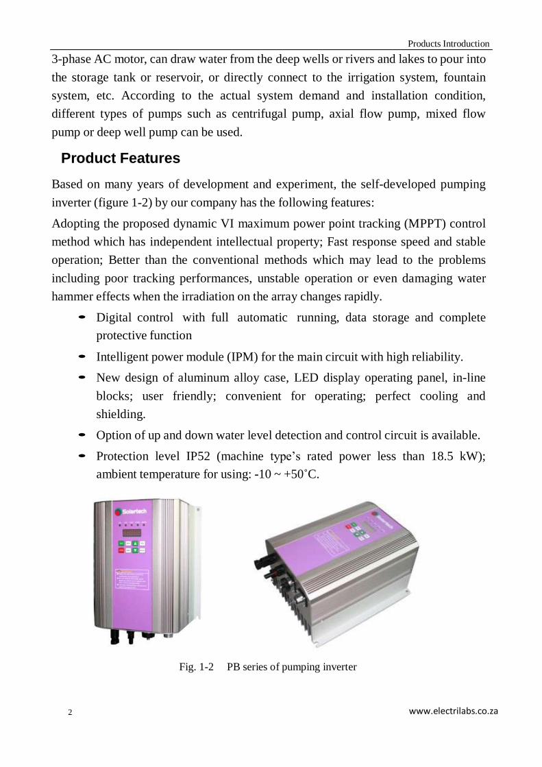
Product Features
Based on many years of development and experiment, the self-developed pumping
inverter (figure 1-2) by our company has the following features:
Adopting the proposed dynamic VI maximum power point tracking (MPPT) control
method which has independent intellectual property; Fast response speed and stable
operation; Better than the conventional methods which may lead to the problems
including poor tracking performances, unstable operation or even damaging water
hammer effects when the irradiation on the array changes rapidly.
• Digital control with full automatic running, data storage and complete
protective function
• Intelligent power module (IPM) for the main circuit with high reliability.
• New design of aluminum alloy case, LED display operating panel, in-line
blocks; user friendly; convenient for operating; perfect cooling and
shielding.
• Option of up and down water level detection and control circuit is available.
• Protection level IP52 (machine type’s rated power less than 18.5 kW);
ambient temperature for using: -10 ~ +50˚C.
Fig. 1-2 PB series of pumping inverter
Products Introduction
3
www.electrilabs.co.za
Inverter Specification
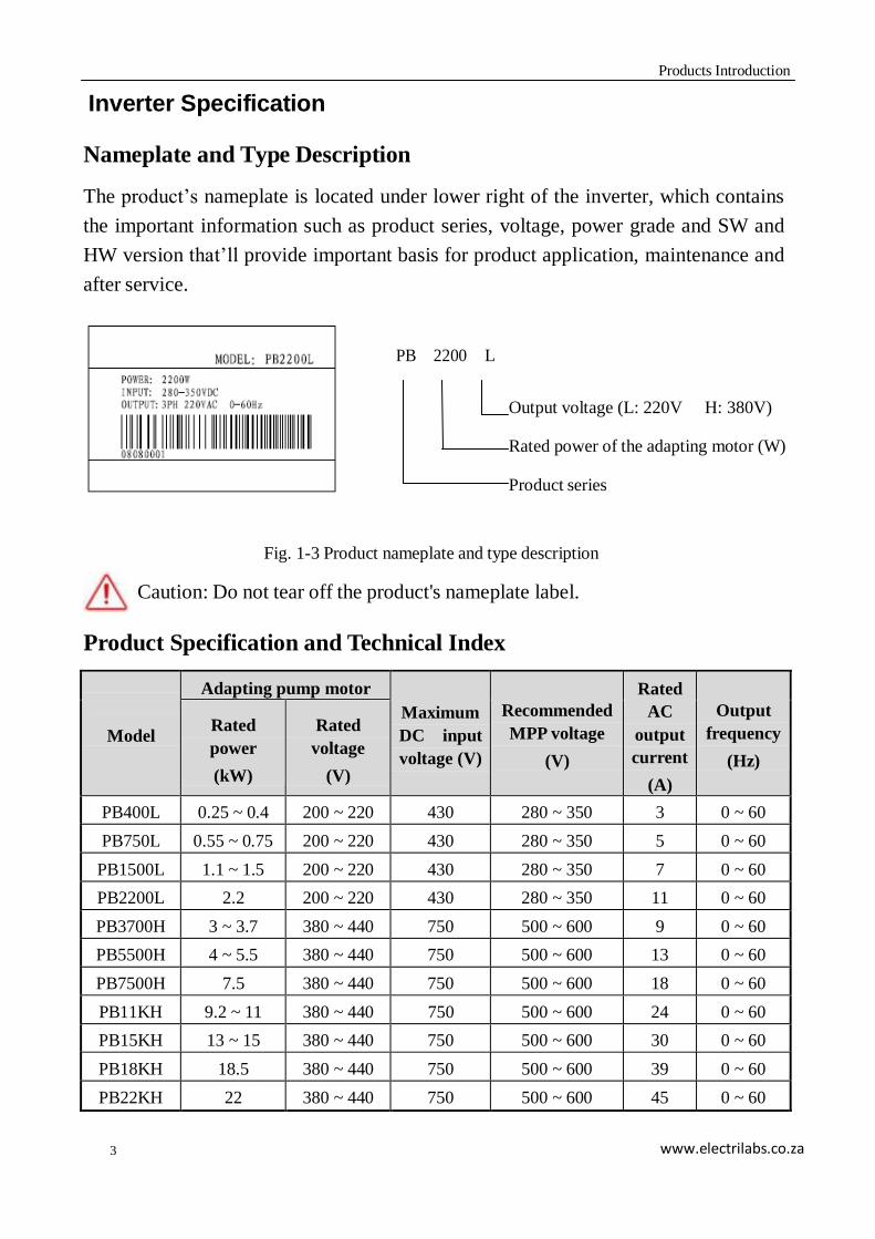
Nameplate and Type Description
The product’s nameplate is located under lower right of the inverter, which contains
the important information such as product series, voltage, power grade and SW and
HW version that’ll provide important basis for product application, maintenance and
after service.
PB 2200 L
Output voltage (L: 220V H: 380V)
Rated power of the adapting motor (W)
Product series
Fig. 1-3 Product nameplate and type description
Caution: Do not tear off the product's nameplate label.
Product Specification and Technical Index
Model
Adapting pump motor Maximum
DC input
voltage (V)
Recommended
MPP voltage
(V)
Rated
AC
output
current
(A)
Output
frequency
(Hz)
Rated
power
(kW)
Rated
voltage
(V)
PB400L 0.25 ~ 0.4 200 ~ 220 430 280 ~ 350 3 0 ~ 60
PB750L 0.55 ~ 0.75 200 ~ 220 430 280 ~ 350 5 0 ~ 60
PB1500L 1.1 ~ 1.5 200 ~ 220 430 280 ~ 350 7 0 ~ 60
PB2200L 2.2 200 ~ 220 430 280 ~ 350 11 0 ~ 60
PB3700H 3 ~ 3.7 380 ~ 440 750 500 ~ 600 9 0 ~ 60
PB5500H 4 ~ 5.5 380 ~ 440 750 500 ~ 600 13 0 ~ 60
PB7500H 7.5 380 ~ 440 750 500 ~ 600 18 0 ~ 60
PB11KH 9.2 ~ 11 380 ~ 440 750 500 ~ 600 24 0 ~ 60
PB15KH 13 ~ 15 380 ~ 440 750 500 ~ 600 30 0 ~ 60
PB18KH 18.5 380 ~ 440 750 500 ~ 600 39 0 ~ 60
PB22KH 22 380 ~ 440 750 500 ~ 600 45 0 ~ 60
Products Introduction
4
www.electrilabs.co.za
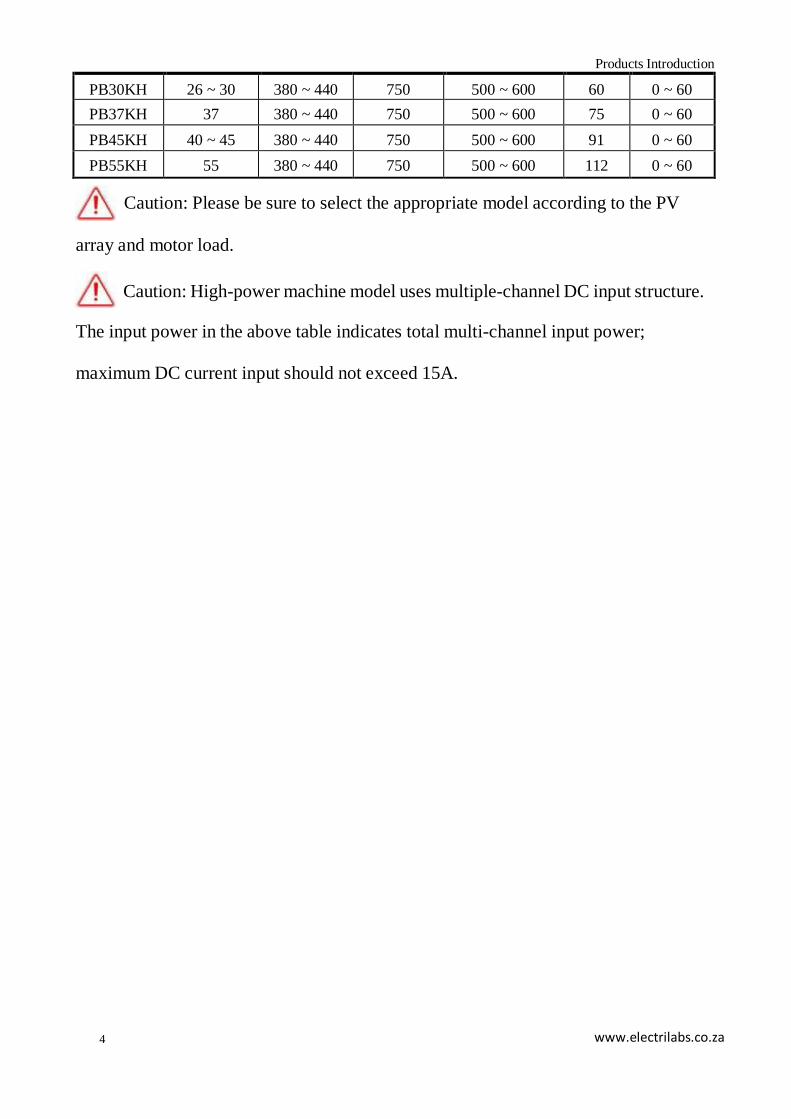
PB30KH 26 ~ 30 380 ~ 440 750 500 ~ 600 60 0 ~ 60
PB37KH 37 380 ~ 440 750 500 ~ 600 75 0 ~ 60
PB45KH 40 ~ 45 380 ~ 440 750 500 ~ 600 91 0 ~ 60
PB55KH 55 380 ~ 440 750 500 ~ 600 112 0 ~ 60
Caution: Please be sure to select the appropriate model according to the PV
array and motor load.
Caution: High-power machine model uses multiple-channel DC input structure.
The input power in the above table indicates total multi-channel input power;
maximum DC current input should not exceed 15A.

5
Installation and Wiring
www.electrilabs.co.za
Chapter 2 Installation and Wiring
Purchase Inspection
Our company has rigid quality assurance system in product manufacturing, package,
etc. If any abnormity is found, please immediately contact the distributors of our
company or directly keep in touch with the technology service center of our company.
We will solve the problems for you immediately. Once you get the product, please
confirm the following items:
Dimension and Weight
Fig. 2-1 Product appearance and installation dimension
Machine
Model
Appearance and installation dimension (mm) Weight
(kg) W H D W1 H1 D1 d
PB400L
PB750L
202.0
209.0
146.0
187.0
197.0
113.0
6.0
3.5
PB1500L
PB2200L
202.0
244.0
146.0
187.0
232.0
113.0
6.0
4.0 ~ 4.3
Solartech
Inspection item Inspection method
Consistency with ordered product Inspect the product’s nameplate label
Damage or exfoliation phenomenon Inspect whole appearance
Completeness of main machine and accessories Check carefully according to the product list
Looseness of fastening parts such as screw If necessary, inspect with screwdriver
6
Installation and Wiring
www.electrilabs.co.za
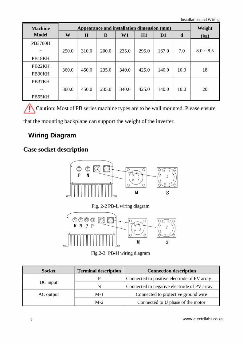
Machine
Model
Appearance and installation dimension (mm) Weight
(kg) W H D W1 H1 D1 d
PB3700H
~
PB18KH
250.0
310.0
200.0
235.0
295.0
167.0
7.0
8.0 ~ 8.5
PB22KH
PB30KH
360.0
450.0
235.0
340.0
425.0
140.0
10.0
18
PB37KH
~
PB55KH
360.0
450.0
235.0
340.0
425.0
140.0
10.0
20
Caution: Most of PB series machine types are to be wall mounted. Please ensure
that the mounting backplane can support the weight of the inverter.
Wiring Diagram
Case socket description
Fig. 2-2 PB-L wiring diagram
Fig.2-3 PB-H wiring diagram
Socket Terminal description Connection description
DC input P Connected to positive electrode of PV array
N Connected to negative electrode of PV array
AC output M-1 Connected to protective ground wire
M-2 Connected to U phase of the motor
7
Installation and Wiring
www.electrilabs.co.za
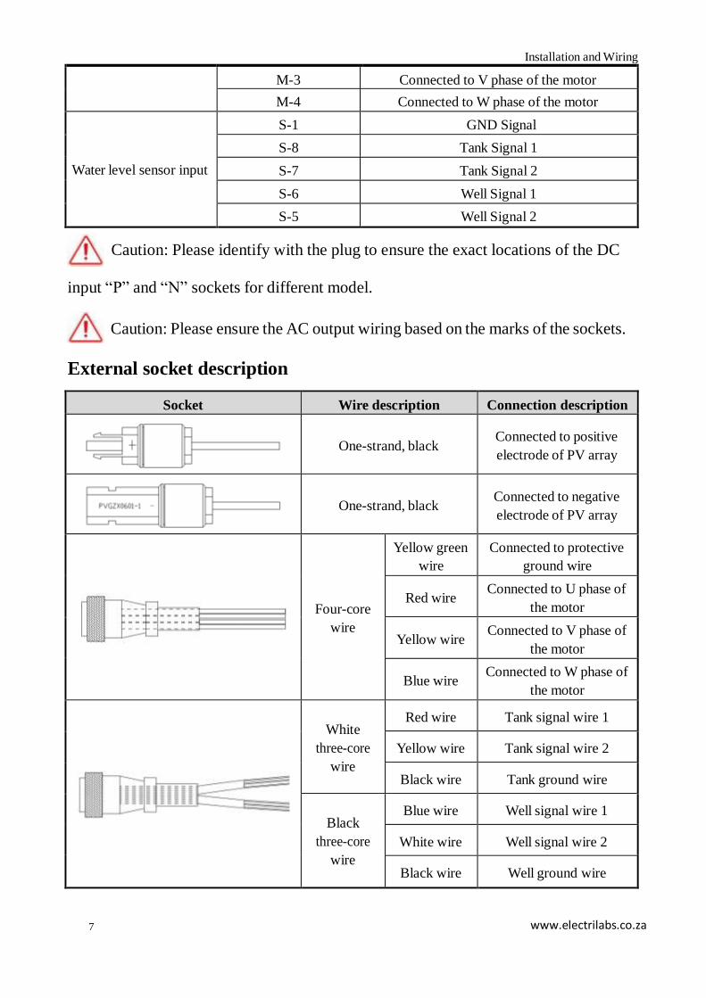
M-3 Connected to V phase of the motor
M-4 Connected to W phase of the motor
Water level sensor input
S-1 GND Signal
S-8 Tank Signal 1
S-7 Tank Signal 2
S-6 Well Signal 1
S-5 Well Signal 2
Caution: Please identify with the plug to ensure the exact locations of the DC
input “P” and “N” sockets for different model.
Caution: Please ensure the AC output wiring based on the marks of the sockets.
External socket description
Socket Wire description Connection description
One-strand, black
Connected to positive
electrode of PV array
One-strand, black
Connected to negative
electrode of PV array
Four-core
wire
Yellow green
wire
Connected to protective
ground wire
Red wire Connected to U phase of
the motor
Yellow wire Connected to V phase of
the motor
Blue wire Connected to W phase of
the motor
White
three-core
wire
Red wire Tank signal wire 1
Yellow wire Tank signal wire 2
Black wire Tank ground wire
Black
three-core
wire
Blue wire Well signal wire 1
White wire Well signal wire 2
Black wire Well ground wire
8
Installation and Wiring
www.electrilabs.co.za
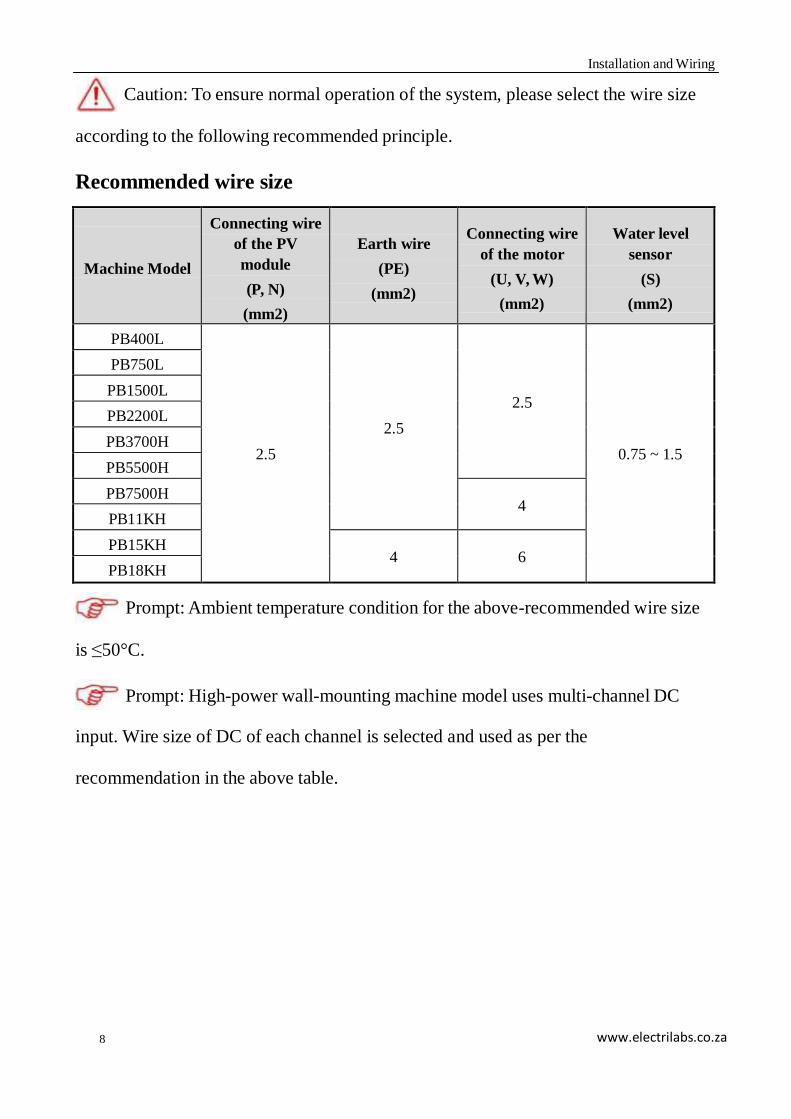
according to the following recommended principle.
Recommended wire size
Machine Model
Connecting wire
of the PV
module
(P, N)
(mm2)
Earth wire
(PE)
(mm2)
Connecting wire
of the motor
(U, V, W)
(mm2)
Water level
sensor
(S)
(mm2)
PB400L
2.5
2.5
2.5
0.75 ~ 1.5
PB750L
PB1500L
PB2200L
PB3700H
PB5500H
PB7500H
4 PB11KH
PB15KH
4
6 PB18KH
Prompt: Ambient temperature condition for the above-recommended wire size
is ≤50°C.
Prompt: High-power wall-mounting machine model uses multi-channel DC
input. Wire size of DC of each channel is selected and used as per the
recommendation in the above table.
Caution: To ensure normal operation of the system, please select the wire size
9
Installation and Wiring
www.electrilabs.co.za
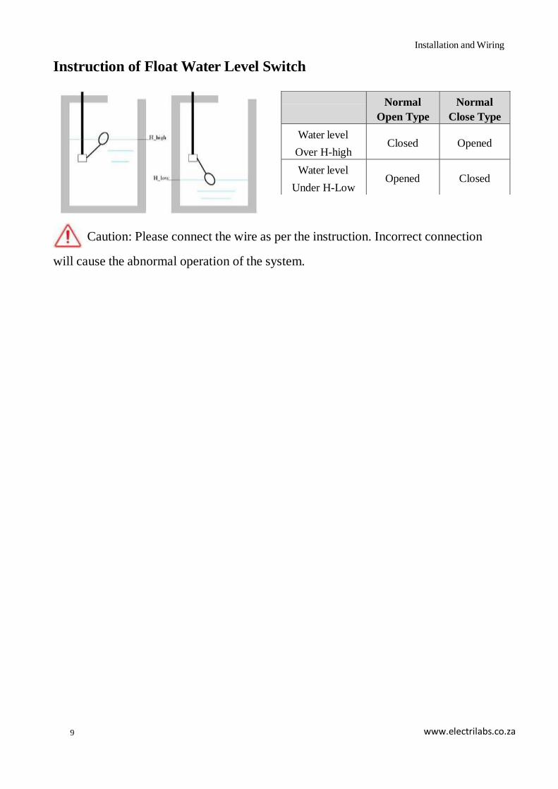
Instruction of Float Water Level Switch
Caution: Please connect the wire as per the instruction. Incorrect connection
will cause the abnormal operation of the system.
Normal
Open Type
Normal
Close Type
Water level
Over H-high
Closed
Opened
Water level
Under H-Low
Opened
Closed
10
Operation Control
www.electrilabs.co.za
Chapter 3 Operation Control
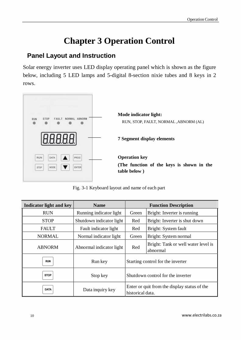
Panel Layout and Instruction
Solar energy inverter uses LED display operating panel which is shown as the figure
below, including 5 LED lamps and 5-digital 8-section nixie tubes and 8 keys in 2
rows.
Mode indicator light:
RUN, STOP, FAULT, NORMAL ,ABNORM (AL)
7 Segment display elements
Operation key
(The function of the keys is shown in the
table below )
Fig. 3-1 Keyboard layout and name of each part
Indicator light and key Name Function Description
RUN Running indicator light Green Bright: Inverter is running
STOP Shutdown indicator light Red Bright: Inverter is shut down
FAULT Fault indicator light Red Bright: System fault
NORMAL Normal indicator light Green Bright: System normal
ABNORM
Abnormal indicator light
Red Bright: Tank or well water level is
abnormal
Run key
Starting control for the inverter
Stop key
Shutdown control for the inverter
Data inquiry key Enter or quit from the display status of the
historical data.

11
Operation Control
www.electrilabs.co.za
Indicator light and key Name Function Description
Mode switch key
1. Switch the contents to be displayed during
data viewing.
2. Switch the digit to be edited during data
editing.
Increment key
1. Increase the parameter number or its
value when the status of the control
parameter is displayed.
2. Change the historical date upward or
display the content of the historical data
by turns when the status of the historical
data is displayed.
3. Increase the output frequency or display
current running data upward by turns
when the data status is displayed during
running.
Decreasing key
1. Decrease the parameter no. or its value
when the status of the control parameter is
displayed.
2. Change the historical date downward or
display the content of the historical data
by turns when the status of the historical
data is displayed.
3. Decrease the output frequency or display
current running data downward by turns
when the data status is displayed during
running.
Programming key Enter or quit from the display status of the
control parameter
Enter key
1. Confirm the content to be viewed or
edited.
2. Confirm and save the parameter value
when the parameter is edited.
+
Reset key Press the combination key to reset in the
protection status.
Operation Method of Panel
Instruction for Display Status
There are 3 kinds of status for operating panel display: running data display, control
parameter display, historical data display. The default status is the status of running
12
Operation Control
www.electrilabs.co.za
data display.
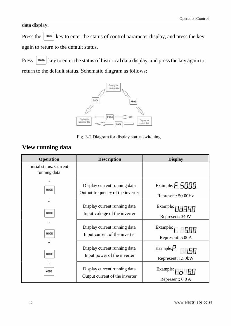
Press the key to enter the status of control parameter display, and press the key
again to return to the default status.
Press key to enter the status of historical data display, and press the key again to
return to the default status. Schematic diagram as follows:
View running data
Fig. 3-2 Diagram for display status switching
Operation Description Display
Initial status: Current
running data
↓
Display current running data
Output frequency of the inverter
Example:
Represent: 50.00Hz ↓
Display current running data
Input voltage of the inverter
Example:
Represent: 340V ↓
Display current running data
Input current of the inverter
Example:
Represent: 5.00A
↓
Display current running data
Input power of the inverter
Example:
Represent: 1.50kW
↓
Display current running data
Output current of the inverter
Example:
Represent: 6.0 A

13
Operation Control
www.electrilabs.co.za
↓
↓
↓
Display current running data
Inverter temperature
Example:
Represent: 37.0℃
Display current running data
Water level sensor status
Example:
Represent: normal water level
Display current running data
Time
Example:
Represent: 12:30
View Historical Data
Operation Description Display
Initial status: non-historical
data display
↓
Enter the data inquiry interface
Display current date
Example:
Represent: Jan 1st. ↓
Select the object to be modified
(day, month, year)
Example:
Modified digit: Scintillation ↓
Modify the date to be inquired
Example:
Represent: Feb second
or
↓
Confirm the date to be inquired Example: Represent:
year 2008
↓
Display historical data
Accumulated generated energy
of the day
Example:
Represent: 9.99°
↓
↓
Display historical data
Maximum power point voltage
of the day
Example:
Represent: 320V
↓
Display historical data
Maximum power of the day
Example:
Represent: 2.20kW
↓
Display historical data
Starting time of the day
Example:
Represent: 5:10
14
Operation Control
www.electrilabs.co.za
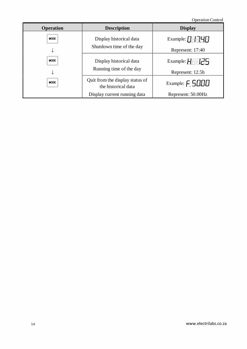
Operation Description Display
↓
↓
Display historical data
Shutdown time of the day
Example:
Represent: 17:40
Display historical data
Running time of the day
Example:
Represent: 12.5h
Quit from the display status of
the historical data
Display current running data
Example:
Represent: 50.00Hz
15
Operation Control
www.electrilabs.co.za
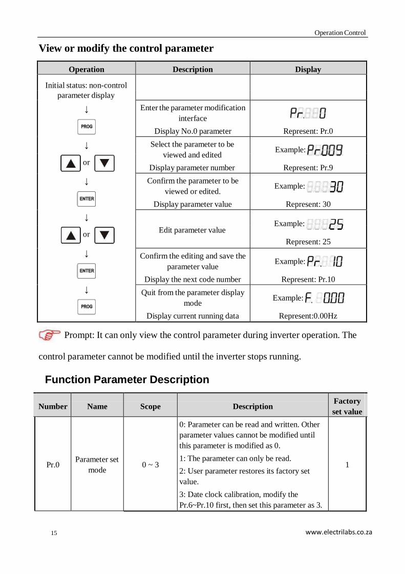
View or modify the control parameter
Operation Description Display
Initial status: non-control
parameter display
↓
Enter the parameter modification
interface
Display No.0 parameter
Represent: Pr.0
↓ Select the parameter to be
viewed and edited
Display parameter number
Example:
Represent: Pr.9 or
↓
Confirm the parameter to be
viewed or edited.
Display parameter value
Example:
Represent: 30
↓
Edit parameter value
Example:
Represent: 25 or
↓
Confirm the editing and save the
parameter value
Display the next code number
Example:
Represent: Pr.10
↓
Quit from the parameter display
mode
Display current running data
Example:
Represent:0.00Hz
Prompt: It can only view the control parameter during inverter operation. The
control parameter cannot be modified until the inverter stops running.
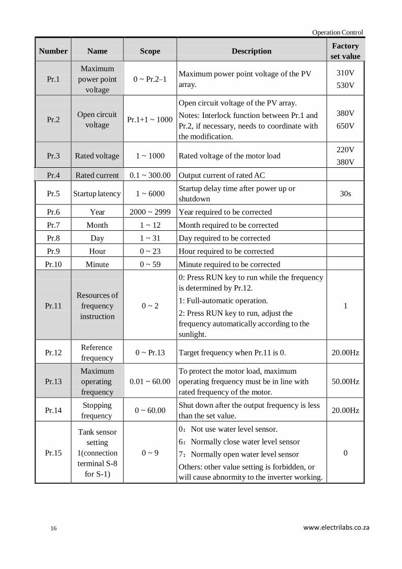
Function Parameter Description
Number
Name
Scope
Description Factory
set value
Pr.0
Parameter set
mode
0 ~ 3
0: Parameter can be read and written. Other
parameter values cannot be modified until
this parameter is modified as 0.
1: The parameter can only be read.
2: User parameter restores its factory set
value.
3: Date clock calibration, modify the
Pr.6~Pr.10 first, then set this parameter as 3.
1
16
Operation Control
www.electrilabs.co.za
Number
Name
Scope
Description Factory
set value
Pr.1
Maximum
power point
voltage
0 ~ Pr.2–1
Maximum power point voltage of the PV
array.
310V
530V
Pr.2
Open circuit
voltage
Pr.1+1 ~ 1000
Open circuit voltage of the PV array.
Notes: Interlock function between Pr.1 and
Pr.2, if necessary, needs to coordinate with
the modification.
380V
650V
Pr.3
Rated voltage
1 ~ 1000
Rated voltage of the motor load 220V
380V
Pr.4 Rated current 0.1 ~ 300.00 Output current of rated AC
Pr.5
Startup latency
1 ~ 6000 Startup delay time after power up or
shutdown
30s
Pr.6 Year 2000 ~ 2999 Year required to be corrected
Pr.7 Month 1 ~ 12 Month required to be corrected
Pr.8 Day 1 ~ 31 Day required to be corrected
Pr.9 Hour 0 ~ 23 Hour required to be corrected
Pr.10 Minute 0 ~ 59 Minute required to be corrected
Pr.11
Resources of
frequency
instruction
0 ~ 2
0: Press RUN key to run while the frequency
is determined by Pr.12.
1: Full-automatic operation.
2: Press RUN key to run, adjust the
frequency automatically according to the
sunlight.
1
Pr.12 Reference
frequency
0 ~ Pr.13
Target frequency when Pr.11 is 0.
20.00Hz
Pr.13
Maximum
operating
frequency
0.01 ~ 60.00
To protect the motor load, maximum
operating frequency must be in line with
rated frequency of the motor.
50.00Hz
Pr.14 Stopping
frequency
0 ~ 60.00 Shut down after the output frequency is less
than the set value.
20.00Hz
Pr.15
Tank sensor
setting
1(connection
terminal S-8
for S-1)
0 ~ 9
0:Not use water level sensor.
6:Normally close water level sensor
7:Normally open water level sensor
Others: other value setting is forbidden, or
will cause abnormity to the inverter working.
0
17
Operation Control
www.electrilabs.co.za
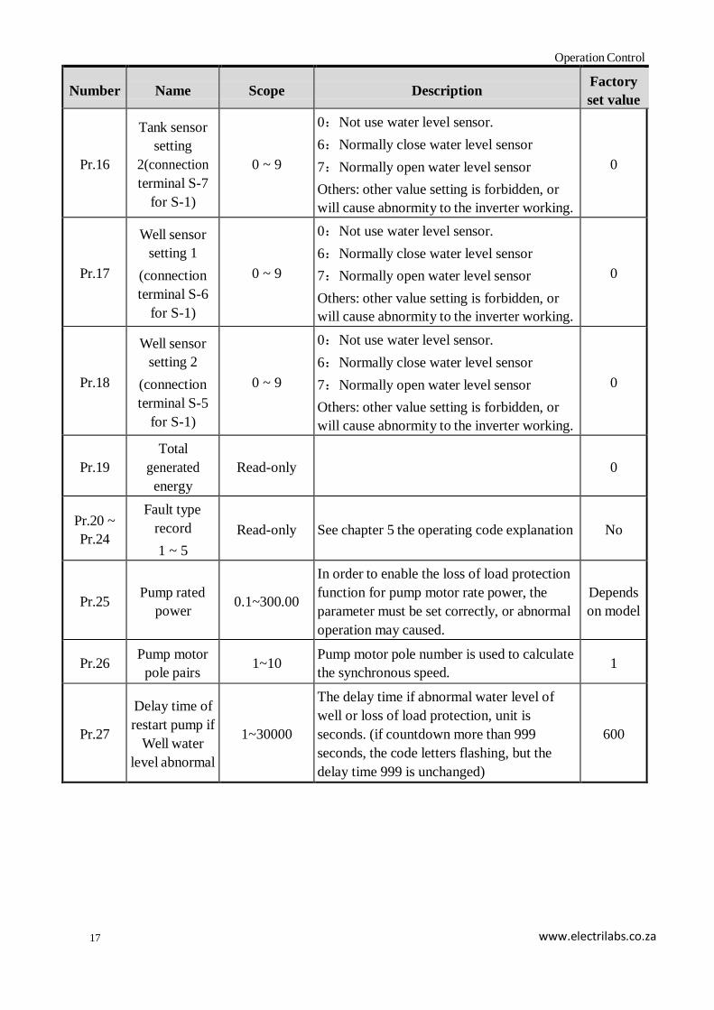
Number
Name
Scope
Description Factory
set value
Pr.16
Tank sensor
setting
2(connection
terminal S-7
for S-1)
0 ~ 9
0:Not use water level sensor.
6:Normally close water level sensor
7:Normally open water level sensor
Others: other value setting is forbidden, or
will cause abnormity to the inverter working.
0
Pr.17
Well sensor
setting 1
(connection
terminal S-6
for S-1)
0 ~ 9
0:Not use water level sensor.
6:Normally close water level sensor
7:Normally open water level sensor
Others: other value setting is forbidden, or
will cause abnormity to the inverter working.
0
Pr.18
Well sensor
setting 2
(connection
terminal S-5
for S-1)
0 ~ 9
0:Not use water level sensor.
6:Normally close water level sensor
7:Normally open water level sensor
Others: other value setting is forbidden, or
will cause abnormity to the inverter working.
0
Pr.19
Total
generated
energy
Read-only
0
Pr.20 ~
Pr.24
Fault type
record
1 ~ 5
Read-only
See chapter 5 the operating code explanation
No
Pr.25
Pump rated
power
0.1~300.00
In order to enable the loss of load protection
function for pump motor rate power, the
parameter must be set correctly, or abnormal
operation may caused.
Depends
on model
Pr.26 Pump motor
pole pairs
1~10 Pump motor pole number is used to calculate
the synchronous speed.
1
Pr.27
Delay time of
restart pump if
Well water
level abnormal
1~30000
The delay time if abnormal water level of
well or loss of load protection, unit is
seconds. (if countdown more than 999
seconds, the code letters flashing, but the
delay time 999 is unchanged)
600

18
Operation Control
www.electrilabs.co.za
Number
Name
Scope
Description Factory
set value
Pr.28
Loss of load
protection is
valid or not
0~1
0:invalid
1:valid(delay time of loss of load protection
is the same as value Pr.27)
Note: When the loss of load protection is
set to valid, the loss of load will determine
only the output frequency is higher than Pr.14
frequency.
0
Pr.29
Delay time of
restart pump if
Tank water
level abnormal
1~30000
The delay time if abnormal water level of
tank, unit is seconds. (if countdown more
than 999 seconds, the code letters flashing,
but the delay time 999 is unchanged)
600
Prompt: After modifying the parameter with shading in the table above, the
next operation cannot be performed until the inverter is reset.
Prompt: Record is not made because of the under-voltage fault of input voltage
caused by the weakness of the sunlight intensity.
Debugging before First Operation
To ensure the efficient, reliable and stable operation of the solar pumping system,
professional electric technician must set partial parameters of the inverter according
to the system structure as following steps before first operation.
Steps Debugging contents Operating method
1
Modify the control
parameter as read-write
parameter
Modify the Pr.0 value as 0.
2
Modify date and time
1. Modify Pr.6~Pr.10 (year, month, day, hour, minute)
according to the date and time.
2. Modify the Pr.0 parameter value as3.
3
Modify PV array
parameter
1. Modify Pr.1 parameter (maximum power point
voltage) according to the cell array.
2. Modify Pr.2 parameter (open circuit voltage)
according to the PV array. (The real measured value ,but
not rated value in the datasheet)
Note: Interlock function between Pr.1 and Pr.2, if
necessary, needs to coordinate with the modification.

19
Operation Control
www.electrilabs.co.za
4
Modify the water level
sensor setting
1. If inverter is matched with tank sensor, modify the Pr.
15, Pr.16 as 8 or as 0.
2. If inverter is matched with well sensor, modify the Pr.
17, Pr.18 as 9 or as 0.
5 Modify rated voltage of
the pump
Modify Pr.3 parameter (rated voltage) according to the
rated voltage of the pump.
6 Modify the maximum
operating frequency
Modify Pr.13 parameter (rated frequency) according to the
pump rated frequency
7
Confirm the motor wiring
1. Modify Pr.11 parameter value as 0.
2. Modify Pr.12 parameter value as 30.00. (in a shining
day)
3. Press to run and observe water yield from the
outlet.
4. Press to shut down and change the order of
output connection.
5. Press to run and observe water yield from the
outlet.
6. Press to shut down, select the wiring method
with larger water yield to ensure the pump’s co-
rotation.
8
Modify the minimum
operating frequency
1. Modify Pr.12 parameter value as 10.00.
2. Press key to run.
3. Observe the effluent of the water outlet.
4. If there is no effluent in the outlet, press to
slowly increase the output frequency.
5. If there is effluent of the pump, record the operating
frequency f0.
6. Modify the Pr.14 parameter value as f0 (shutdown
frequency).
9
Set the operating mode of
the inverter
User sets Pr.11 (operating mode) according to his own
demand.
0: Press key to operate, the initial frequency value
is determined by Pr.12, then modify the output frequency

20
Operation Control
www.electrilabs.co.za
by pressing or .
1: Full-automatic operation: the inverter will start
automatically if the sunlight is strong enough, the output
frequency will track automatically according to the
sunlight. The control cell array will export maximum
power.
2: Press to run, output frequency will track
automatically according to the sunlight. The control cell
array will export maximum power.
10 Modify the control
parameter as read-only.
Modify the Pr.0 parameter value as 1 before the inverter
start up.
Caution: Please do not modify the control parameters of the inverter randomly,
or else it will cause abnormal working of the system.
21
Fault Diagnosis
www.electrilabs.co.za
Chapter 4 Fault Diagnosis
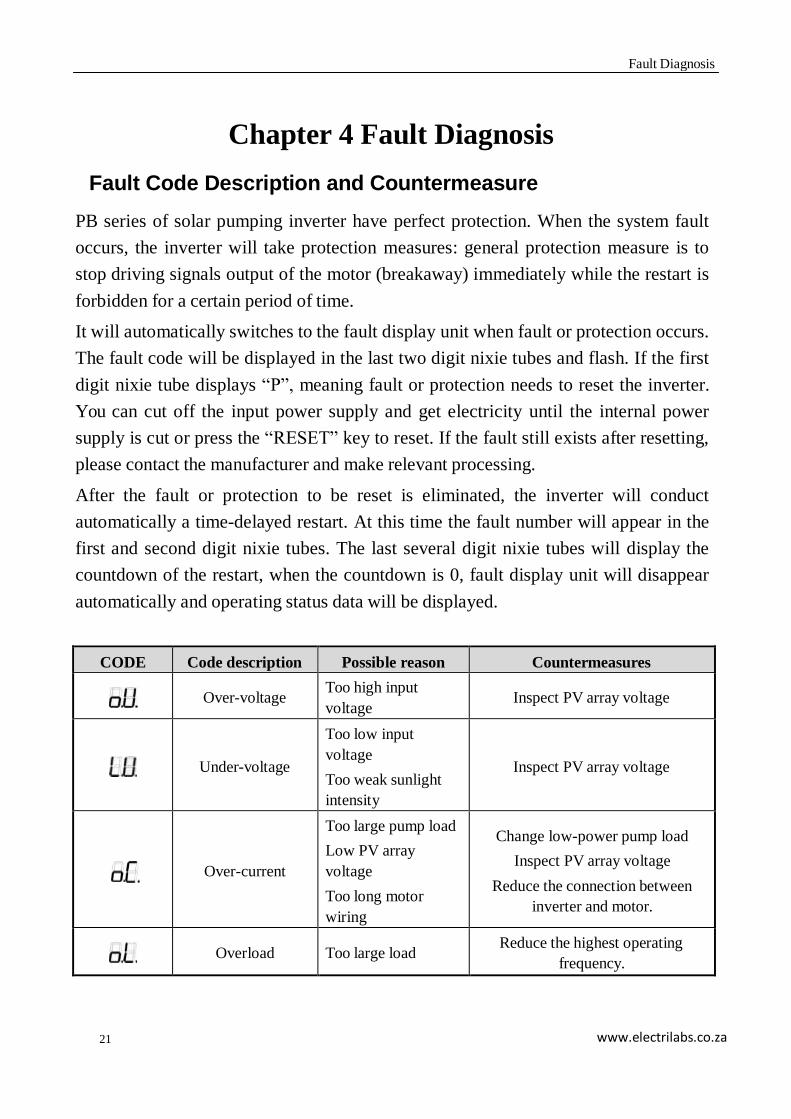
Fault Code Description and Countermeasure
PB series of solar pumping inverter have perfect protection. When the system fault
occurs, the inverter will take protection measures: general protection measure is to
stop driving signals output of the motor (breakaway) immediately while the restart is
forbidden for a certain period of time.
It will automatically switches to the fault display unit when fault or protection occurs.
The fault code will be displayed in the last two digit nixie tubes and flash. If the first
digit nixie tube displays “P”, meaning fault or protection needs to reset the inverter.
You can cut off the input power supply and get electricity until the internal power
supply is cut or press the “RESET” key to reset. If the fault still exists after resetting,
please contact the manufacturer and make relevant processing.
After the fault or protection to be reset is eliminated, the inverter will conduct
automatically a time-delayed restart. At this time the fault number will appear in the
first and second digit nixie tubes. The last several digit nixie tubes will display the
countdown of the restart, when the countdown is 0, fault display unit will disappear
automatically and operating status data will be displayed.
CODE Code description Possible reason Countermeasures
Over-voltage Too high input
voltage
Inspect PV array voltage
Under-voltage
Too low input
voltage
Too weak sunlight
intensity
Inspect PV array voltage
Over-current
Too large pump load
Low PV array
voltage
Too long motor
wiring
Change low-power pump load
Inspect PV array voltage
Reduce the connection between
inverter and motor.
Overload
Too large load Reduce the highest operating
frequency.

22
Fault Diagnosis
www.electrilabs.co.za
Over-current of the
module
Shorted output or
grounding
Module damaged
Inspect the connection
Turn to manufacturer for service
Over-temperature of
the module
Air duct blocked
Too high ambient
temperature
Clear the air duct or improve the
ventilation condition
AC CT fault Device or circuit
damaged
Turn to manufacturer for service
DC CT fault Device or circuit
damaged
Turn to manufacturer for service
Data record fault Device or circuit
damaged
Turn to manufacturer for service
pump running
empty
Pumping empty,
pump wire are all
broken, pump is not
match with inverter.
To check with water level, pump
wire connection, pump rate is match
with inverter capacity or not.
Communication
fault
Device or circuit
damaged
Reset
Turn to manufacturer for service
Description for Other Codes
CODE Code description Relevant description
Parameter initialization
Return to normal after resetting
Important parameter
modification
Return to normal after resetting
Inverter type
: 200V series; : rated power 1.5 kW
Start time-delay
Countdown of the restart: 30 s
water level sensor 1 is
abnormal
When water level is normal, system will be
normal automatically before delayed-restart.
water level sensor 2 is
abnormal
When water level is normal, system will be
normal automatically before delayed-restart.
water level sensor 3 is
abnormal
When water level is normal, system will be
normal automatically before delayed-restart.
water level sensor 4 is
abnormal
When water level is normal, system will be
normal automatically before delayed-restart.
water level sensor 1,2
matching use are abnormal
When water level is normal, system will be
normal automatically before delayed-restart.

23
Fault Diagnosis
www.electrilabs.co.za
CODE Code description Relevant description
water level sensor 3,4
matching use are abnormal
When water level is normal, system will be
normal automatically before delayed-restart.
Voltage of PV panel is too
low to start.
Low irradiation or Pr.2 setting error
Module voltage less than starting voltage
Fault Inquiry and Reset
This series of inverters record the fault codes of the latest 5 times. Searching this
information will help find the fault cause. Fault information is stored together with the
control parameter, code numbers are Pr.20 ~ Pr.24. Please refer to the keyboard
operation method to search and find out relevant information.
When the inverter fault occurs, by pressing and keys simultaneously or
cutting off the power supply to restore normal operation.
Caution: Completely check up on the fault cause and eliminate it before
resetting. If it can not be reset or goes wrong after resetting, check up on the cause,
because continuous resetting will damage the inverter.
Caution: Delay 5 minutes to reset during overload and overheat protection.
24
Service and Maintenance
www.electrilabs.co.za
Chapter 5 Service and Maintenance
Routine Inspection and Maintenance
Affected by ambient temperature, humidity, dust, vibration and internal device aging
of the inverter, the inverter will appear some potential problems during operation. To
make the inverter run stably for longer time, a periodic inspect must be exerted every
year.
Requirement of Inspection and Maintenance
1. The inspection must be performed by professional technical personnel, if
necessary, cut off power supply of the inverter first.
2. Avoid leaving the metal components in the inverter, or else it will cause
damage to the equipment.
3. Electric insulation test has been made on the inverter before it is leaving
factory, so the user doesn’t have to carry on a withstand-voltage test.
4. If it is necessary to conduct insulation test on the inverter, all the input and
output terminals must be reliably shorted. It is forbidden to conduct
insulation test on single terminal. Use the 500V megohm meter to conduct
the test.
5. It is forbidden to use the megohm meter to test in the control circuit.
6. When conducting insulation test on the motor, you have to dismantle the
connection between motor and inverter.
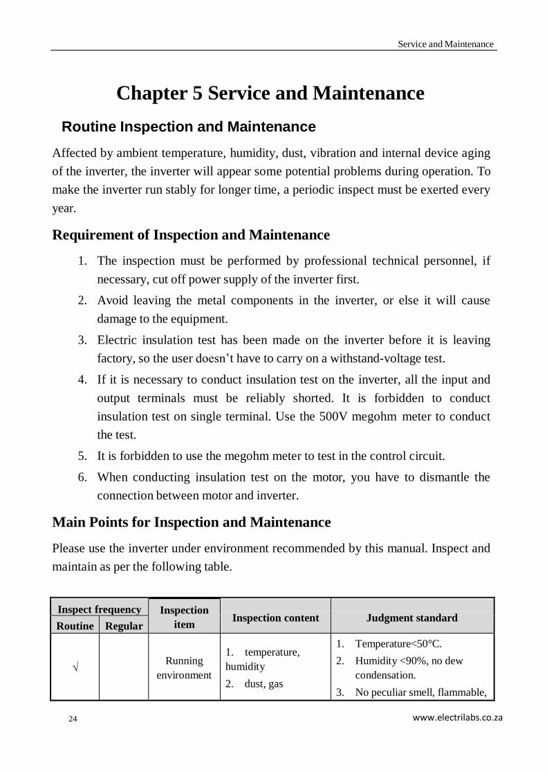
Main Points for Inspection and Maintenance
Please use the inverter under environment recommended by this manual. Inspect and
maintain as per the following table.
Inspect frequency Inspection
item
Inspection content
Judgment standard Routine Regular
√
Running
environment
1. temperature,
humidity
2. dust, gas
1. Temperature<50°C.
2. Humidity <90%, no dew
condensation.
3. No peculiar smell, flammable,
25
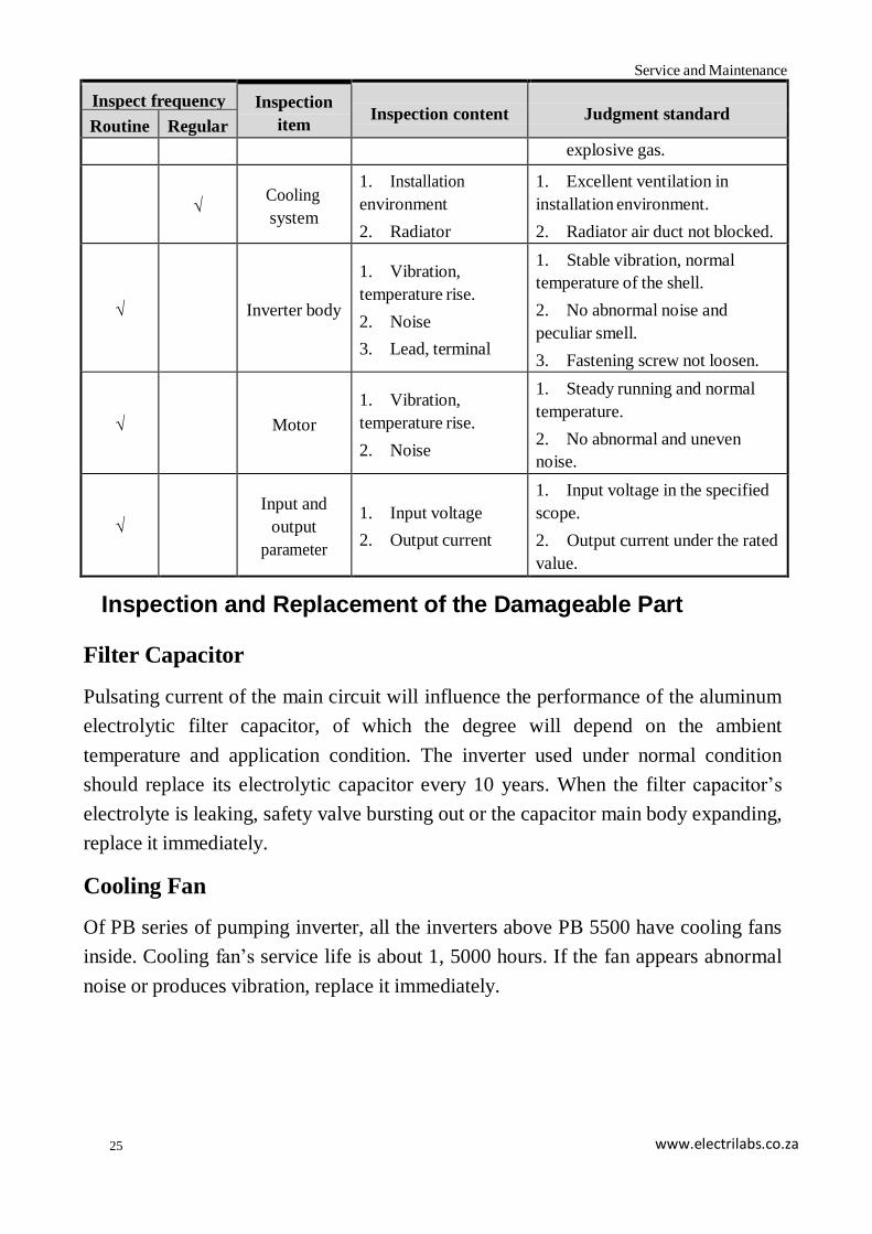
Service and Maintenance
www.electrilabs.co.za
Inspect frequency Inspection
item
Inspection content
Judgment standard Routine Regular
explosive gas.
√
Cooling
system
1. Installation
environment
2. Radiator
1. Excellent ventilation in
installation environment.
2. Radiator air duct not blocked.
√
Inverter body
1. Vibration,
temperature rise.
2. Noise
3. Lead, terminal
1. Stable vibration, normal
temperature of the shell.
2. No abnormal noise and
peculiar smell.
3. Fastening screw not loosen.
√
Motor
1. Vibration,
temperature rise.
2. Noise
1. Steady running and normal
temperature.
2. No abnormal and uneven
noise.
√
Input and
output
parameter
1. Input voltage
2. Output current
1. Input voltage in the specified
scope.
2. Output current under the rated
value.
Inspection and Replacement of the Damageable Part
Filter Capacitor
Pulsating current of the main circuit will influence the performance of the aluminum
electrolytic filter capacitor, of which the degree will depend on the ambient
temperature and application condition. The inverter used under normal condition
should replace its electrolytic capacitor every 10 years. When the filter capacitor’s
electrolyte is leaking, safety valve bursting out or the capacitor main body expanding,
replace it immediately.
Cooling Fan
Of PB series of pumping inverter, all the inverters above PB 5500 have cooling fans
inside. Cooling fan’s service life is about 1, 5000 hours. If the fan appears abnormal
noise or produces vibration, replace it immediately.
26
Service and Maintenance
www.electrilabs.co.za
Storage and Warranty
Storage
If the storage is not used temporarily or stored for long time after purchasing, the
following notice should be paid attention to:
Avoid placing the inverter in high temperature or humid place or where there is
vibration and metal dust, and excellent ventilation should be ensured.
Inside filter capacitor performance of the inverter will decline for long–time disuse. It
is necessary to energize one time every 2 years to restore the performance of the filter
capacitor and inspect the inverter function at the same time. It is necessary to increase
the voltage through a DC power supply during energizing with power-on time not less
than 5 hours.
Warranty
The warranty of this inverter is three years. When any fault or damage occurs on the
product, within the warranty period, our company will provide free maintenance.
After the warranty time, we can provide lifetime paid warranty service.
Certain maintenance charge should be considered during warranty period if the fault
is caused by the following reason:
1. Fault caused by operating against the manual or surpass the standard
specification
2. Fault caused by self fix and modification without permission.
3. Fault caused by poor preservation
4. Fault by using the inverter in abnormal function
5. Machine damage caused by fire, salt corrosion, gas corrosion, earthquake,
storm, flood, lightning, abnormal voltage or other force majeure.
Prompt: Warranty only covers the body of the inverter.

27
www.electrilabs.co.za
Warranty Card
Client name
Contact person
Client address
Telephone number
Product type
Date of purchase
Machine frame code
Warranty length
(from the leaving
factory day.)
Distributor (Seal)
1. Main machine, 1
Packing List
2. Operation manual( including warranty card), 1
3. Plug of the positive electrode of the PV array, 1
4. Plug of the negative electrode of the PV array, 1
5. AC output plug, 1
6. Water level sensor plug, 1 (matching)

www.electrilabs.co.za
Warranty Agreement
1. The warranty of this inverter is two years. When any fault or damage
occurs on the product, within the warranty period, our company will
provide free maintenance. After the warranty time, we can provide
lifetime paid warranty service.
2. The warranty time starts from the date when the product is leaving the
factory, and the machine frame code is the only proof to determine the
warranty period.
3. Certain maintenance charge should be considered during warranty
period if the fault is caused by the following reason:
a) Fault caused by operating against the manual or surpass the
standard specification
b) Fault caused by self fix and modification without permission.
c) Fault caused by poor preservation
d) Machine damage caused by fire, salt corrosion, gas corrosion,
earthquake, storm, flood, lightning, abnormal voltage or other force
majeure.
4. Please be sure to retain this card and show it to the maintenance service.
Infinite Solar Energy