download (266kb) - university of huddersfield repository
TRANSCRIPT

University of Huddersfield Repository
Kassier, Rafael, Lee, Hyunkook, Brookes, Tim and Rumsey, Francis
An informal comparison between surround microphone techniques
Original Citation
Kassier, Rafael, Lee, Hyunkook, Brookes, Tim and Rumsey, Francis (2005) An informal comparison between surround microphone techniques. In: Audio Engineering Society 118th Convention, 28-31 May 2005, Barcelona, Spain.
This version is available at http://eprints.hud.ac.uk/id/eprint/9681/
The University Repository is a digital collection of the research output of theUniversity, available on Open Access. Copyright and Moral Rights for the itemson this site are retained by the individual author and/or other copyright owners.Users may access full items free of charge; copies of full text items generallycan be reproduced, displayed or performed and given to third parties in anyformat or medium for personal research or study, educational or not-for-profitpurposes without prior permission or charge, provided:
• The authors, title and full bibliographic details is credited in any copy;• A hyperlink and/or URL is included for the original metadata page; and• The content is not changed in any way.
For more information, including our policy and submission procedure, pleasecontact the Repository Team at: [email protected].
http://eprints.hud.ac.uk/

Audio Engineering Society
Convention Paper 6429Presented at the 118th Convention
2005 May 28–31 Barcelona, Spain
This convention paper has been reproduced from the author's advance manuscript, without editing, corrections, or consideration by the Review Board. The AES takes no responsibility for the contents. Additional papers may be obtained by sending request and remittance to Audio Engineering Society, 60 East 42nd Street, New York, New York 10165-2520, USA; also see www.aes.org. All rights reserved. Reproduction of this paper, or any portion thereof, is not permitted without direct permission from the Journal of the Audio Engineering Society.
AN INFORMAL COMPARISON BETWEEN SURROUND-SOUND
MICROPHONE TECHNIQUES Rafael Kassier1, Hyun-Kook Lee2, Tim Brookes3, and Francis Rumsey4
Institute of Sound Recording, University of Surrey, Guildford, GU2 7XH, UK
1 [email protected]; 2 [email protected]; 3 [email protected]; 4 [email protected]
ABSTRACT There is currently a lack of recorded test materials in five-channel surround format. Particularly lacking are recordings made simultaneously using different microphone arrays that would allow comparative switching between different recorded versions of the same acoustical event. An ambitious pilot experiment was conducted involving the recording of various different programme items using eight different recording techniques simultaneously. This was undertaken to determine the practicality of making of such recordings, to allow informal comparisons between microphone techniques, and to create a set of simultaneous multichannel recordings for subsequent perceptual evaluation. This paper details experimental design considerations and practical limitations, as well as reporting initial observations regarding the resulting recordings.
1. INTRODUCTION AND BACKGROUND
There is currently a lack of recorded audio test material in five-channel surround format (also known as 3/2 stereo reproduction [1]). Particularly lacking are recordings made simultaneously using different microphone arrays that allow listeners to switch instantaneously between different recorded versions of the same acoustical event in order to compare them. Such recordings could be of use in a variety of applications including as test material in the evaluation
of spatial audio listener training schemes, and in microphone and loudspeaker tests on either transducers or systems. They could also be used as a training aid for recording engineers. A pilot experiment was conducted to:
• Determine the practicalities of the making of such recordings.
• Determine the feasibility of making the recordings on location.
• Gain Experience in using various multichannel recording techniques.

Kassier et. al Informal microphone techniques comparison.
AES 118th Convention, Barcelona, Spain, 2005 May 28–31 Page 2 of 17
• Allow informal comparisons between microphone techniques (to determine the characteristics of each technique).
• Create a set of different simultaneous multichannel recordings for subsequent perceptual evaluation.
It is intended that this paper will provide useful information to recording engineers wishing to experiment with surround sound techniques, as well as providing a report on the experimental techniques used and a presentation and discussion of the results of some informal comparisons between the techniques.
2. RECORDING TECHNIQUE CONSIDERATIONS
Rumsey [2] suggests a way of classifying the design concepts of the current microphone techniques intended for five-channel reproduction, based upon the purpose of the rear channels in the technique. According to his classification, there are two main groups: those that use ‘five-channel main microphone techniques’ and those that use ‘techniques with front and rear separation’. Five-channel main microphone techniques consist of five microphones that are placed relatively close to one another, forming a single array (normally a front triplet with two microphones further back). Each microphone signal is routed to one of the loudspeakers in 3/2 stereo reproduction: Left (L), Centre (C), Right (R), Left Surround (LS) and Right Surround (RS). Such microphone techniques aim to provide satisfying directional images and spatial impression simultaneously with a fixed pattern of microphone placement. Theile [3], however, points out that the realisation of natural images requires much effort because of the complicated relationship between the psychoacoustic parameters involved. For example, accurate localisation will rely on the precedence effect across the various two-channel stereo segments (for example, between L & C, or R & RS in the 3/2 stereo configuration) due to the short distances between the microphones. The listening position and front-rear balance will therefore affect the performance of the technique [2]. Furthermore, the fixed positions and polar patterns of the front and rear microphones would result in an inevitable compromise between the representation of optimised directional images and spatial or room impression. For example, the front triplet should be optimised not only with respect to the recording angle (see below) of direct sound from the
front but also with respect to the balance of direct and indirect sound intensity in conjunction with the rear microphones [3]. In addition, the position and directivity of the rear microphone array should not be decided exclusively for the characteristics of the ambient sound, but also for the suppression of the direct sound due to the relatively short distance between the front and the rear microphones. ‘Techniques with front and rear separation’, on the other hand, use a ‘front’ main microphone array that is used specifically to record the direct sound, together with a separate ‘rear’ microphone array that is intended to pick-up decorrelated ambient sound to supply (primarily) the rear loudspeakers. Usually the front microphone array is a variation of a conventional stereo technique or the front triplet of a five-channel main microphone technique. Different rear microphone arrays can be combined with different front arrays depending on desired directional and ambience characteristics [3]. The distance between the front and the rear arrays can vary depending on different recording situations. The further the rear array is from the recorded sources, the more early reflections, the higher the reverberant-to-direct ratio and the higher the density of reflections. However, at least 10dB suppression of the direct sound is required in the rear channels versus the front channels [3]. ‘Techniques with front and rear separation’ afford recording engineers more freedom to choose ‘front’ and ‘rear’ microphone techniques depending on the desired characteristics of frontal image and spatial impression than fixed 5-channel main microphone arrays. Moreover, they enable the engineer to subjectively balance the direct and ambient sounds using artistic and technical judgement. In this respect, microphone techniques with front and rear separation appear to be more practical in a wider range of recording applications. The flexibility to allow the combination of ‘front’ and ‘rear’ techniques also make these methods ideal for the creation of the multiple simultaneously recorded surround-sound recordings required from this pilot experiment.
3. SELECTED MICROPHONE TECHNIQUES
In order to determine the feasibility of the methods chosen for location recording, it was important to maximise the number of different simultaneous multichannel recordings possible when recording 24 channels of audio. 24 recorded channels is the
Kassier et. al Informal microphone techniques comparison.
AES 118th Convention, Barcelona, Spain, 2005 May 28–31 Page 3 of 17
maximum number that can easily be accommodated on location (a 24-track hard disk recording unit or 3 synchronously ganged 8-track tape recorders). A method was devised to allow 16 different 5-channel recordings to be created simultaneously using 24 channels of audio. By recording four different 3-channel ‘front’ microphone arrays and four different ‘rear’ microphone arrays (two with 2-channels, two with 4-channels), it was possible to combine one of the ‘front’ techniques with one of the ‘rear’ techniques to create sixteen different configurations for reproduction using 3/2 stereo. Limitations in the quantity and directivity of microphones available during the recordings made it impossible to use 24 similar microphones or microphones of the specified directivity for all of the techniques selected. Attempts were made to use the same microphone types within each array, as far as availability allowed. Comparison of the techniques themselves will need to be treated with caution. Ideally, the recordings should be made with similar microphones of the specified directivity (for example, 24 Schoeps CMC-5U microphones with appropriate directivity capsules) for the comparisons between techniques to be as fair as possible. The recording angle of a microphone array is the angle (subtended around the centre line) between the left and right most edges of the sound stage that appear in the left and right edges of the reproduction [4]. If the recorded sound stage subtends a wider angle about the microphone array than the array’s recording angle, the sources outside the angle will all be reproduced (bunched) in the left or right speakers respectively. The four ‘front’ triplets and four ‘rear’ recording arrays used in the recordings are described below. The recording angles of the first three front techniques were similar to each other (108°, 118°, and 120°), while that of the last technique was much larger than the others. The ‘front’ arrays were centred at the same location to allow the stereophonic scope of the phantom images produced by the first three techniques to be similar in order to make a controlled comparison between the techniques.
3.1. Front Microphone ‘Triplet’ Techniques All three-channel ‘front’ techniques described here use a triplet of microphones that are subsequently used routed to L, C & R in the 3/2 stereo configuration.
3.1.1. Fukada Tree
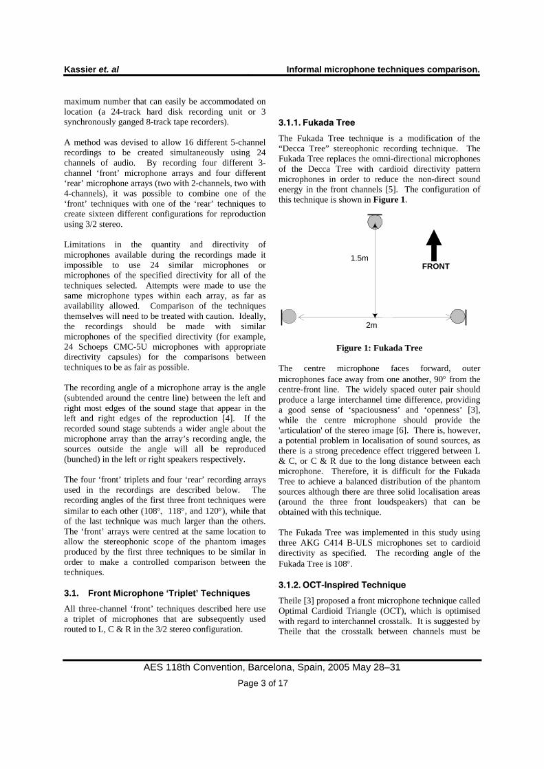
The Fukada Tree technique is a modification of the “Decca Tree” stereophonic recording technique. The Fukada Tree replaces the omni-directional microphones of the Decca Tree with cardioid directivity pattern microphones in order to reduce the non-direct sound energy in the front channels [5]. The configuration of this technique is shown in Figure 1.
Figure 1: Fukada Tree The centre microphone faces forward, outer microphones face away from one another, 90° from the centre-front line. The widely spaced outer pair should produce a large interchannel time difference, providing a good sense of ‘spaciousness’ and ‘openness’ [3], while the centre microphone should provide the 'articulation' of the stereo image [6]. There is, however, a potential problem in localisation of sound sources, as there is a strong precedence effect triggered between L & C, or C & R due to the long distance between each microphone. Therefore, it is difficult for the Fukada Tree to achieve a balanced distribution of the phantom sources although there are three solid localisation areas (around the three front loudspeakers) that can be obtained with this technique. The Fukada Tree was implemented in this study using three AKG C414 B-ULS microphones set to cardioid directivity as specified. The recording angle of the Fukada Tree is 108°.
3.1.2. OCT-Inspired Technique
Theile [3] proposed a front microphone technique called Optimal Cardioid Triangle (OCT), which is optimised with regard to interchannel crosstalk. It is suggested by Theile that the crosstalk between channels must be
2m
1.5mFRONT

Kassier et. al Informal microphone techniques comparison.
AES 118th Convention, Barcelona, Spain, 2005 May 28–31 Page 4 of 17
reduced as much as possible in order to obtain accurate localisation characteristics. OCT employs a cardioid centre microphone just 0.08m in front of two outer supercardioid directivity microphones. The outer microphones are faced towards the sides in order to obtain maximum channel separation. The recording angle is adjustable depending on the spacing between the outer microphones, and this flexibility can be important for recording engineers to have freedom of microphone array placement, to control direct/indirect sound balance and also to create sound colour [3]. The OCT-inspired technique used in this experiment is shown in Figure 2. It employs a cardioid capsule for the centre microphone and hypercardioid capsules for the outer microphones. Three AKG C414 EB microphones were used to implement the OCT-inspired technique in this experiment.
Figure 2: OCT Technique
For this experiment, the distance between the outer microphones was chosen to be 0.7m in order to achieve a recording angle of 118°.
3.1.3. INA-3 Technique
The INA-3 technique [4] is based upon the ‘critical linking’ technique, proposed by Williams & Le Du [7, 8]. ‘Critical linking’ intends to attach the left (L-C) and right (R-C) segments of the reproduced frontal sound image without overlap, and thus aims to provide a balanced and continuous presentation of the reproduced sound image across L-C-R in the 3/2 stereo configuration. This ‘critical linking’ is achieved by using either ‘electronic offset’ or ‘microphone position offset’. The electronic offset is created by adding a certain value of intensity difference or time difference to the time and intensity function. The microphone position offset is achieved by changing the physical position of the microphones to adjust the time and intensity differences of the array. It is suggested that the array must be placed so that the outer microphones
point to the edges of the recording stage in order to obtain the full spread of the stereo image, provided that the centre microphone points to the centre [4]. Figure 3 shows the configuration of INA-3 technique used in this experiment.
Figure 3: INA-3 Technique
The angle between the outer microphones (and hence the recording angle) for the INA-3 array used for the current experiment was 120°. The INA-3 technique was implemented in this study using three AKG C451 microphones with cardioid directivity capsules (as specified).
3.1.4. Near-Coincident-Inspired Technique
Klepko [9] proposed a near-coincident front triplet, which consists of three microphones placed in line with a distance of 0.175m between each adjacent microphone. The centre microphone should be directed forwards with the outer microphones angled at ±30° from the centre-front line. See Figure 4.
Figure 4: Near-Coincident Technique
Klepko suggests the need to avoid producing a strong phantom centre image between the left and right channels since there is already an additional centre microphone. For this reason the outer channels employ a super-cardioid directivity pattern microphone, while the centre channel uses a cardioid microphone. However, as Theile [3] points out that this technique suffers from a serious interchannel crosstalk problem despite the use of supercardioid microphones. Theile
0.70m
0.08m
FRONT
0.92m
0.27m
FRONT
0.175m 0.175m
FRONT

Kassier et. al Informal microphone techniques comparison.
AES 118th Convention, Barcelona, Spain, 2005 May 28–31 Page 5 of 17
also affirms that there is a large and inevitable overlapping between the recording area L-C and C-R because the recording angles of each microphone pair are wide due to the small angle between the microphones and the use of a more directional polar pattern on one channel. The most dominant effects of interchannel crosstalk are an increase in source width and a decrease in locatedness according to [10]. The wide recording angle may also result in a narrow stereo image when using a normal microphone distance from the stage. The near-coincident-inspired technique was implemented in this study using three Neumann KM84 cardioid directivity microphones (as no supercardioid microphones were available for the outer channels). This would have probably given rise to stronger interchannel crosstalk, thus reproducing wider and more poorly localised sound sources than would have been the case if supercardioid directivity microphones had been available.
3.2. 4-Channel ‘Rear’ Microphone Techniques In four-channel ‘rear’ microphone techniques, four microphones are used to record diffuse reverberation. The signals from these microphones are generally reproduced using the L, R, LS and RS speakers in a standard 3/2 stereophonic loudspeaker configuration. A study by Hiyama et al [11] showed that four loudspeakers in the L, R, LS & RS positions in 3/2 stereo could reproduce a spatial impression close to that of a twelve loudspeaker encircled configuration (when reproducing decorrelated reverberation). The use of four channels should therefore be beneficial when compared to the two-channel techniques employed in five-channel main microphone arrays.
3.2.1. IRT-Cross-Inspired Technique
Theile proposed a four-channel rear microphone array called ‘IRT-Cross’ [3]. It consists of four (normally cardioid) microphones arranged in a square of side 0.2m to 0.25m wide, with each microphone at the corner of the square pointing away from the centre. This array is optimised for recording ambience, but can be disadvantageous with regard to crosstalk from the direct sound (because the front two microphones facing towards the front corners may not have a sufficiently suppressed direct sound pick-up). Theile [3] suggests that the spacing between the microphones can be decided depending on the recording situation and the
desired characteristics of spatial image, although he recommends the distance of 20-25cm. Closer microphone spacings provide a more balanced distribution of enveloping sources, whilst wider spacings provide more diffused reverberation. Extreme spacing of either too close or too wide causes a loss of envelopment [3]. The polar pattern of the microphones can be also chosen depending on the situation. The implementation used in this experiment used a microphone spacing of 30cm to allow the microphones used in the recordings to fit together in the cross arrangement. See Figure 5.
Figure 5: IRT-Cross-Inspired Technique
Due to a shortage of available microphones of suitable directivity and quality, the IRT-Cross-inspired technique implemented in this experiment used a pair of Oktava Mk-012-01 cardioid pattern microphones pointing towards the front left and front right, and a pair of AKG C460B microphones with CK61-ULS cardioid pattern capsules pointing to the back left and back right.
3.2.2. Hamasaki-Square Technique
Another four-channel rear microphone array is the ‘Hamasaki-Square’. It employs dipole microphones pointing to the left or right of the centre-line so that their dead-axes are facing forward. This is in order to reduce the crosstalk from the direct sound as much as possible. The distance between each microphone was originally suggested to be 1m [12], but this was later adjusted to 2-3m based upon calculation and subjective listening tests [13]. Their calculation of cross-correlation-coefficient between two omni directional microphones in the reverberant field showed that the distance of 2m provided decorrelation above 100Hz, which seem to fulfil the requirement for the perception of spatial impression. They also conducted a subjective listening test in order to compare the spatial impression between each pair of 1m, 2m and 3m distances, and found that most of the listeners participated in the test preferred 3m to 2m, and 2m to 1m. The array is usually
0.30m
0.30m
FRONT

Kassier et. al Informal microphone techniques comparison.
AES 118th Convention, Barcelona, Spain, 2005 May 28–31 Page 6 of 17
placed far away from the sound stage and at a high position in the recording space in order to obtain the maximum ratio of reverberant to direct sound. Theile [3] suggests that this array is a better option for achieving good spatial impression compared to the IRT-Cross. The pair of microphones furthest towards the front are routed to channels L and R or panned between L-LS and R-RS, and the pair of microphones furthest towards the rear are routed to channels LS and RS. The degree of L-LS or R-RS panning is dependent on the amount of desired spatial information in the front loudspeakers, and also seems to rely on the headroom of spatial image in the front array that is used in combination. The Hamasaki Square configuration implemented in this experiment is shown in Figure 6.
Figure 6: Hamasaki-Square Technique
It uses four Schoeps CMC-5U microphones with dipole directivity capsules. The positive lobes of the dipoles faced away from the centre of the array. The recorded signals were routed to L, R, LS & RS in the 3/2 stereo reproduction.
3.3. 2-Channel ‘Rear’ Microphone Techniques 2-channel rear techniques normally route the signals from two microphone channels to the LS and RS loudspeakers in the 3/2 stereo loudspeaker configuration.
3.3.1. Dummy Head Technique
Klepko [9] proposed using a dummy-head binaural microphone in order to provide a ‘continuous’ lateral spatial impression. He affirms that the problems of high frequency acoustical crosstalk that are present when the binaural signals are reproduced through the loudspeakers are solved naturally when the dummy head is used for the rear channels. As the rear
loudspeakers are placed almost at the sides of the listener, the listener’s head acts as a diffracting barrier to frequencies above 1kHz, which carry the most effective HRTF cues. The maximum crosstalk rejection is achieved when the rear loudspeakers are positioned exactly at ±90° of the listener, where the maximum differences between the ear signals are produced. In the listening test using the dummy head microphone coupled with the ‘near-coincident front’ triplet described above, Klepko found that continuous and clear spatial image were created between ± 30° and ± 90°. Klepko stated that the distance between the front triplet and the dummy head was 1.24m, but the reason of the spacing is not explained. Despite the acoustical crosstalk rejection between the rear channels by the head shadow effect, the interchannel crosstalk relationship between the front channels and the dummy head is likely to be poor. Since the dummy head is facing the front and the distance from the front array is relatively short, the crosstalk from the direct sound will have large intensity and short time delay (about 0.38ms). This might be critical with regard to accurate localisation of the front image. In this respect, if the dummy head technique was used as a separate rear microphone array, it might be a more reasonable way to place the microphone further back from the front array in order to reduce the direct energy as much as possible. In this experiment, a dummy head (Cortex MK2) was positioned with the ‘rear’ microphone techniques, about 7m from the centre of the ‘front’ arrays. It was faced forwards.
3.3.2. Spaced Cardioid Technique
In this experiment, a technique was also used consisting of two cardioid microphones (Brüel & Kjær 4011) directed away from the direct sound. Each pointed towards the respective rear wall corners of the studio. They were also positioned as far back and as far apart from one another as was possible to capture as much reverberant sound as possible. This was done in order to reject as much of the direct sound as possible. They were placed 8m apart, with each microphone 4m from the centre-front line of the studio.
4. EXPERIMENTAL SET-UP
The recording sessions took place in Studio 1 in the Department of Music and Sound Recording at the University of Surrey.
2m
2m
FRONT
Kassier et. al Informal microphone techniques comparison.
AES 118th Convention, Barcelona, Spain, 2005 May 28–31 Page 7 of 17
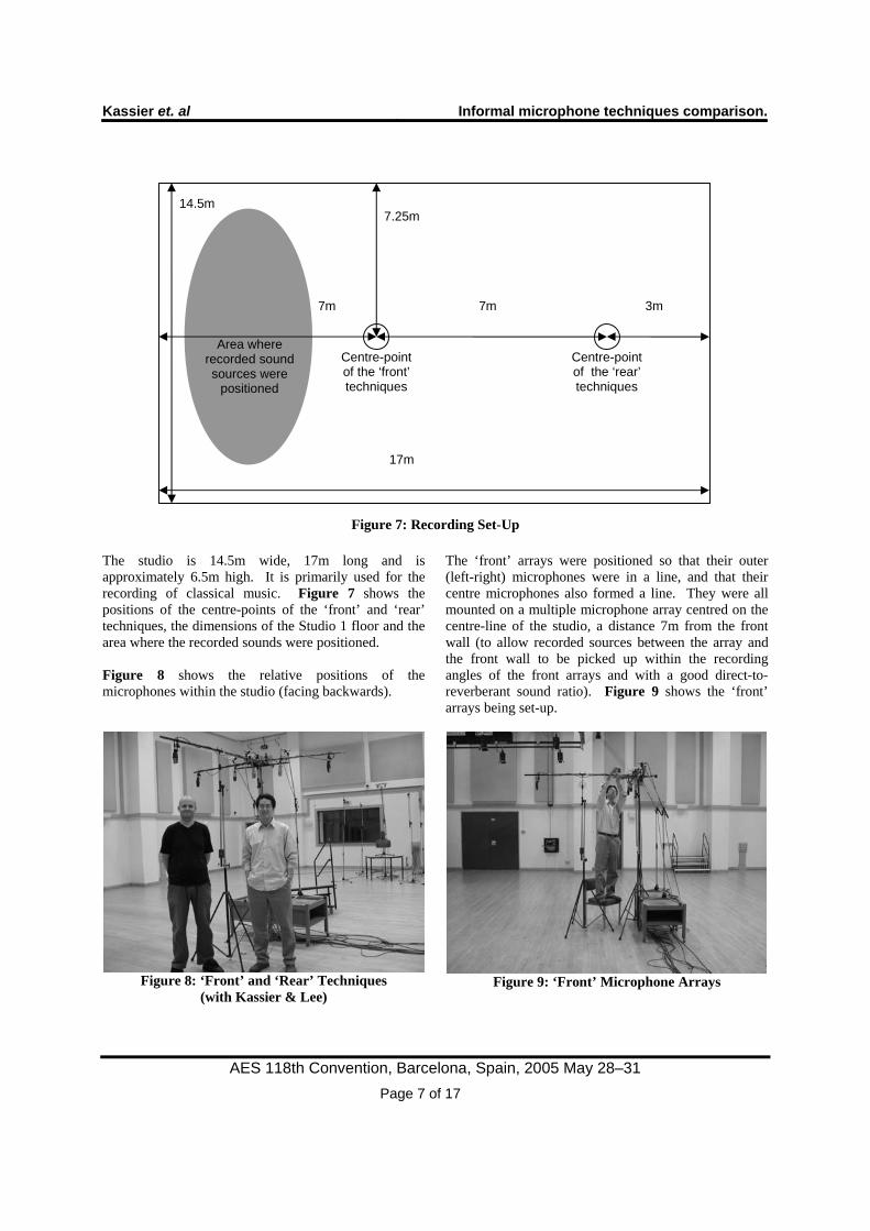
Figure 7: Recording Set-Up
The studio is 14.5m wide, 17m long and is approximately 6.5m high. It is primarily used for the recording of classical music. Figure 7 shows the positions of the centre-points of the ‘front’ and ‘rear’ techniques, the dimensions of the Studio 1 floor and the area where the recorded sounds were positioned. Figure 8 shows the relative positions of the microphones within the studio (facing backwards).
Figure 8: ‘Front’ and ‘Rear’ Techniques
(with Kassier & Lee)
The ‘front’ arrays were positioned so that their outer (left-right) microphones were in a line, and that their centre microphones also formed a line. They were all mounted on a multiple microphone array centred on the centre-line of the studio, a distance 7m from the front wall (to allow recorded sources between the array and the front wall to be picked up within the recording angles of the front arrays and with a good direct-to-reverberant sound ratio). Figure 9 shows the ‘front’ arrays being set-up.
Figure 9: ‘Front’ Microphone Arrays
7m 7m 3m
Centre-point of the ‘front’ techniques
Centre-point of the ‘rear’ techniques
Area where recorded sound sources were
positioned
14.5m
17m
7.25m

Kassier et. al Informal microphone techniques comparison.
AES 118th Convention, Barcelona, Spain, 2005 May 28–31 Page 8 of 17
As for the rear arrays, they were ‘centred’ on the dummy head which was placed 7m behind the front arrays (about 3m from the far wall). The two four-channel techniques (IRT-Cross-inspired technique and Hamasaki Square) were positioned so that the dummy head was at their centres, and the Spaced Cardioid technique microphones were spaced 4m from the centre points (8m from one another), measured perpendicular to the centre-line of the studio. The rear microphones were raised as high as the microphone stands would allow. Figure 10 shows the rear microphone arrays in more detail. The IRT-Cross can be seen as four microphones positioned high up above the dummy head. The Hamasaki Square consists of the four microphones positioned about the dummy head on separate stands. The right spaced cardioid microphone can be seen on the far left of the picture, angled towards the right rear corner of the studio.
Figure 10: ‘Rear’ Microphone Arrays
(left spaced cardioid not shown) The 24 microphone signals (four ‘front’ triplets, two four-channel surround techniques and two two-channel surround techniques) were connected to the inputs of an analogue mixing console (Neve V series). They were recorded using three ganged 8-track digital recording tape recorders (Sony PCM-800). Each microphone and the channels of the dummy head were level aligned using a small portable tone generator held at 15cm from the capsule (or pinna on the dummy head). Recording levels were not altered during any of the recordings (except the Harpsichord – see below – where the level of all channels was boosted 5dB). The recordings were later transferred to a digital audio workstation (Digidesign Pro Tools HD) from the digital tapes to allow editing and the creation of separately mixed multichannel sound files for use in subjective testing.
The transfer was done over analogue connections and sampled into Pro Tools at 16 bits and at 44.1kHz.
5. RECORDING THE PROGRAMME ITEMS
Recording sessions took place during a week in August 2004. A large number of programme items were able to be recorded due to the availability of a number of musicians from the University of Surrey Music Department and members and friends of the Institute of Sound Recording (IoSR). Instrumentalists were positioned within the shaded area shown in Figure 7, between the front wall and the front microphone techniques. Different positions were sometimes used to allow the recording of similar sound sources in a variety of positions. The following items were recorded:
• Six different solo piano items (performed by two artistes). Piano positioned centrally and about 5m from the centre of the front arrays. See Figure 11.
• Solo trombone, positioned to the right of the centre line (looking forward) about 4m from the centre of the front arrays.
• 3 different items of piano-accordion, positioned about 30° to the left of the centre line, about 4m from the centre of the front arrays.
• 2 pieces solo soprano voice. The singer was positioned to the right of the centre line and about 4m from the centre of the front arrays.
• 2 pieces accompanied soprano voice. The singer was positioned about 30° to the right of the centre line and about 4m from the centre of the front arrays. The piano was positioned centrally and about 5m from the centre of the front arrays.
• Solo violin, positioned about 4m from the centre of the front arrays.
• Accompanied violin. The violinist was positioned to the right of the centre line and about 4m from the centre of the front arrays. The piano was positioned centrally and about 5m from the centre of the front arrays.
• Percussion ‘ensemble’ involving a conga drum at 60° to the left of the centre line, triangle 30° to the left, tambourine 30° to the right, and snare drum 60° to the right. All instrumentalists were positioned about 4m from the centre of the front arrays.

Kassier et. al Informal microphone techniques comparison.
AES 118th Convention, Barcelona, Spain, 2005 May 28–31 Page 9 of 17
• Male and female speech (in Korean). Recorded at about 4m from the centre of the front arrays, at 0° and ±30° and ±60° from the centre line.
• Percussion instruments (Conga, high and low Tom Tom, Bongos and Triangle). Recorded at about 4m from the centre of the front arrays, at 0° and ±30° and ±60° from the centre line.
• 2 different items of solo trumpet, recorded at about 4m from the centre of the front arrays, at 0° and ±30° and ±60° from the centre line.
• Jazz item for accompanied trumpet. Trumpet positioned about 30° to the right of the centre line and about 4m from the centre of the front arrays. The piano was positioned between 30° and 60° to the left of the centre line and about 4m from the centre of the front arrays. See Figure 12.
• 2 items for harpsichord, recorded at 0° and about 4m from the centre of the front arrays. See Figure 13.
• Solo clarinet, recorded at about 4m from the centre of the front arrays, at 0° and ±30° and ±60° from the centre line.
Figure 11: Piano Recording Session
Figure 12: Accompanied Trumpet Recording Session
Figure 13: Harpsichord Recording Session

Kassier et. al Informal microphone techniques comparison.
AES 118th Convention, Barcelona, Spain, 2005 May 28–31 Page 10 of 17
6. INFORMAL MICROPHONE TECHNIQUES COMPARISONS: BACKGROUND AND SELECTED PROGRAMME ITEMS
As already mentioned, due to the variety of microphones used in this experiment, and their occasional non-conformity with the originally intended specifications, any comparisons between the various microphone techniques should be undertaken with caution. However, it was felt that the wider audio community may benefit from the presentation of informal comparisons of the various techniques used in this study. For example, recording engineers wishing to experiment with surround-sound microphone techniques could use this as a starting point for their own experimentation. Initial informal listening tests conducted by the authors indicated that there was surprisingly little difference in perceived effect between the Spaced Cardioid microphones and the dummy head, when routed to the surround channels. There was also surprisingly little subjective difference between the reproduction of the Hamasaki-Square and IRT-Cross arrays (whose four channels were each routed to L, R, LS and RS when active). In addition, the most predominant subjective audio attribute that appeared to be changing when the different front microphone techniques were auditioned was the spatial width of the recorded sources or ensembles (SC Width as defined in [14]). For a series of subjective tests involving a spatial audio listener training scheme (not reported here), it was decided to reduce the number of ‘rear’ techniques to just two (one 4-channel technique and one 2-channel technique). The Hamasaki Square and Spaced Cardioid techniques were chosen, making a total of eight possible different combinations of the different front and rear techniques. Furthermore, twelve short loops were selected from the recorded materials. Individual multichannel sound files were created for each technique and each loop for reproduction via the test computer (a Silicon Graphics (SGI) O2 running proprietary listening test software “ALEX”). The selected programme items were:
1. Piano (more continuous music from a romantic era Sonata)
2. Piano (staccato music from a 20th century Toccata)
3. Harpsichord (a minimalist piece for keyboard played on the harpsichord)
4. Piano-Accordion (a mixture of continuous and
transient music) 5. Solo Soprano (romantic era aria) 6. Accompanied Soprano (renaissance era aria) 7. Solo Violin (a baroque era solo sonata) 8. Accompanied Violin (modern Christian
‘worship’ music) 9. Solo Trumpet (traditional melody, relatively
continuous) 10. Accompanied Trumpet (jazz) 11. Solo Clarinet (classical clarinet concerto
played solo, relatively continuous) 12. Solo Trombone (bombastic music, relatively
staccato) Each item was created using the various signals as they were recorded from the microphones with no level adjustment (as previously discussed, all signals levels during the Harpsichord recordings were boosted by 5dB). Initial attempts at subjective and objective loudness equalisation proved to lessen the width changes between the various items. The items were also being used in a subjective experiment involving subjective perception of source and ensemble width (SC Width as defined in [14]). Due to these loudness-dependent width changes, loudness equalisation of the items was abandoned. This did, however, mean that the microphone gain in all channels of the techniques remained controlled, as did the recording angle for the first three ‘front’ techniques, ensuring that the results should be repeatable and comparable within this context. Interpretations between the microphone techniques (particularly subjective judgements of quality [15]) need to be interpreted with this in mind. The eight different recording technique combinations for the above twelve items were rated by eight experienced listeners according to the width of the source or ensemble as it is reproduced over 3/2 stereo configuration loudspeakers (details of these tests are not reported here). The programme items were also subjected to an informal comparison by six of the eight experienced listeners, in order to find common ground between the subjective perceptions reported by the listeners and to investigate how their preferences differ between the various microphone techniques and the various programme items.
7. INFORMAL MICROPHONE TECHNIQUES COMPARISONS: METHOD
The listening tests were conducted in the Listening Room of the Institute of Sound Recording, University of

Kassier et. al Informal microphone techniques comparison.
AES 118th Convention, Barcelona, Spain, 2005 May 28–31 Page 11 of 17
Surrey. The acoustical parameters of this room conform to the requirements of the ITU-R Recommendation BS. 1116 [16]. Five loudspeakers (Genelec 1032A) were arranged in 3/2 stereo configuration according to the ITU-R BS. 775 Recommendation [1]. The distance between the centre of each loudspeaker stand and the listening position was 2m. A computer monitor and mouse were situated in front and below the listening position to allow the subjects to control the test computer. Six experienced listeners took part in the informal comparisons (five members of the University of Surrey’s Institute of Sound Recording and one final-year undergraduate student on the Tonmeister course who had had experience in recording classical music in surround format). A computer (Silicon Graphics SGI O2) running proprietary listening test software (ALEX) displayed a screen with 96 buttons which controlled the reproduction of the 8 different combinations of front and rear techniques for each of the 12 items, allowing instantaneous switching between the various techniques. The buttons were coded for each front and rear technique combination in order to allow subjects to develop an idea of the common features of each individual technique, and to assess the differences between the techniques. Due to the informal nature of the tests and the fact that all items were marked and simultaneously available, no attempt was made to randomise their position on screen. Subjects were asked to decide on a preferred reproduction method for each of the items, and for all items in general. They were also asked to provide comments on spatial changes in line with [14] if possible, and any other perceived differences between the different techniques. Each subject was given as much time as they needed to complete the task (which ranged from about 30 minutes to about 90 minutes).
8. RESULTS
Preferences were collected from each subject for each of the twelve programme items and an overall preference for all the items. Comments provided about the relative differences between the techniques were also collected and summarised. The bar graphs displayed in the Results and Appendix sections show not only the relative preference for each
front technique, but also the relative preference for each rear technique when used with each of the front techniques. The combined vertical bars show the total preference for each ‘front’ technique. Each vertical bar is split into the preference for the combination of the respective front technique with each of the two rear techniques. The white portion of the vertical bar - when present - indicates the relative preference for the Hamasaki Square used in combination with the front technique in question. The black portion of the vertical bar - when present - indicates the relative preference for the Spaced Cardioid technique used in combination with the front technique in question.
8.1. Overall Preference Figure 14 shows the total number of times each technique was chosen as the preferred item. There is a clear overall ‘winner’ in both ‘front’ and ‘rear’ technique groups, the Fukada Tree and the Hamasaki Square. The INA-3 technique was the only other ‘front’ technique to be preferred with any great conviction (nearly twenty counts across all subjects and programme items). The OCT-inspired technique and Near-Coincident-inspired technique were chosen only very occasionally (less than ten times each across all subjects and all items). The two-channel Spaced Cardioid ‘rear’ technique was preferred much less frequently than the four-channel Hamasaki Square in general, but where the OCT-inspired technique, or Near-Coincident-inspired technique were preferred, subjects preferred them in combination with the Spaced Cardioid rear technique equally or with greater regularity than with the Hamasaki Square.
Spaced CardioidHamasaki Square
Rear Technique
Bars show counts
Fukada OCT Nr.Coinc. INA
Front Technique
10
20
30
40
Cou
nt
Figure 14: Overall Preference. All Subjects. All
Programme Items.

Kassier et. al Informal microphone techniques comparison.
AES 118th Convention, Barcelona, Spain, 2005 May 28–31 Page 12 of 17
This was confirmed when the subjects were asked to state their overall preference for front and rear techniques (shown in Figure 15). Five of the six subjects preferred the Fukada Tree, whereas one preferred the INA-3 technique. Two subjects stated that they preferred the Spaced Cardioid rear technique, but the individual programme item preferences for one of these subjects showed that they had actually preferred techniques involving the Hamasaki Square more times than the Spaced Cardioid array (this subject later suggested that it could have been due to the order in which they rated the items – with mainly solo wind items at the end which they preferred with the Spaced Cardioid array).
Spaced CardioidHamasaki Square
Rear Technique
Bars show counts
Fukada INA
Front Technique
1
2
3
4
5
Cou
nt
Figure 15: Stated Overall Preference. All Subjects.
All Programme Items.
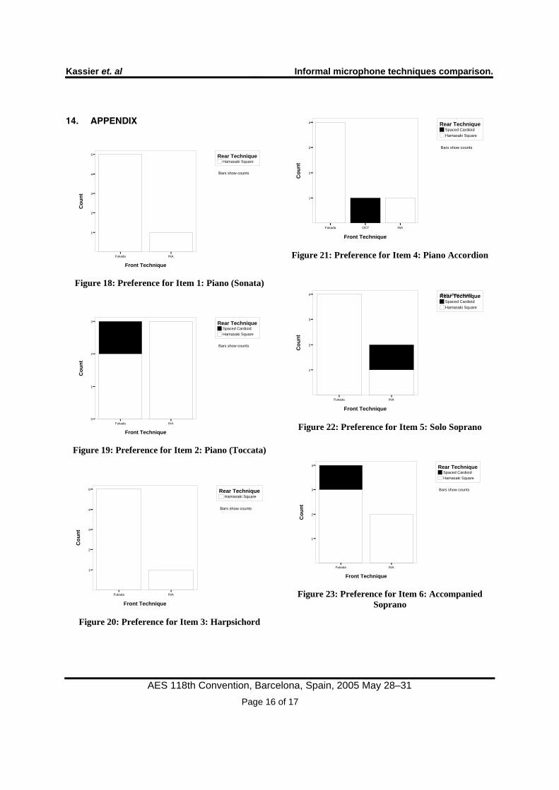
8.2. Individual Programme Item Preference Regarding the individual programme items themselves, the individual items showed a variation in the preferred microphone techniques. See Figure 18 - Figure 29 in the Appendix. For most items (items 1-8, 10 & 12), the Fukada Tree was preferred with subjects occasionally preferring INA-3. Figure 16 shows the combined preferences for these particular items.
Spaced CardioidHamasaki Square
Rear Technique
Bars show counts
Fukada OCT INA
Front Technique
10
20
30
40
Cou
nt
Figure 16: Combined preference for items 1-8, 10 &
12 For the more staccato piano item (Item 2), the INA-3 was preferred as much as the Fukada Tree. See Figure 19. The OCT-inspired technique was never the most preferred item, but was a strong second to the Fukada Tree technique for item 10, the accompanied trumpet. See Figure 27. Two programme items, however, show a very different trend to the others. They are Item 9 (solo trumpet), and Item 11 (solo clarinet). Both showed a preference for the Near-Coincident-inspired technique over the others. Fukada Tree was the second preferred choice of subjects for items 9 and 11. See Figure 26 and Figure 28 for the individual graphs, and Figure 17 for the combined preference across the solo clarinet and trumpet items.
Spaced CardioidHamasaki Square
Rear Technique
Bars show counts
Fukada OCT Nr.Coinc. INA
Front Technique
0
2
4
6
Cou
nt
Figure 17: Combined preference for items 9 & 11

Kassier et. al Informal microphone techniques comparison.
AES 118th Convention, Barcelona, Spain, 2005 May 28–31 Page 13 of 17
8.3. Individual Recording Techniques Comments
8.3.1. Fukada Tree Technique Comments
There was a general consensus among subjects that the Fukada Tree technique provided:
• Good/natural distance to the recorded sources (SC Distance according to [14])
• Appropriate/balanced width of sources or ensembles (SC Width according to [14])
• Good/balanced spatial context • Good timbral balance / warm / best low
frequency extension
8.3.2. OCT-Inspired Technique Comments
There was a general consensus among subjects that the OCT-inspired technique recordings featured:
• Sources that were distant/too distant (SC Distance according to [14]).
o More distant than the Fukada Tree technique
• Sources that were narrow / too narrow (SC Width according to [14])
o Narrower than the Fukada Tree technique
• Reproduction that was too muddy / not present enough
• Sources that were easy to localise
8.3.3. Near-Coincident-Inspired Technique Comments
Subjects tended to comment that the Near-Coincident-inspired technique provided:
• Sources and ensembles that were too close (SC Distance according to [14])
• Sources and ensembles that were too wide (SC Width according to [14])
• Phasiness and unstable sources • Good recordings of solo wind instruments
8.3.4. INA-3 Technique Comments
Comments about the INA-3 technique showed that subjects thought the technique:
• Lacks low frequencies / was quite thin / had a narrower frequency spectrum
• Produces sources that are difficult to localise • Is not as full spatially / has wide environment
width (as defined in [14]) / was often the best spatially (especially with more than one
source) • Was spatially the most wide and open / open or
airy sound
8.3.5. Rear Techniques Comments
On the whole, the comparison of the rear techniques showed that the Hamasaki Square was preferable to the Spaced Cardioid because it:
• Blended the ambience from the rear with that from the front / was more coherent
• Produced wider sources (SC Width according to [14])
• Was more enveloping (Environment Envelopment according to [14])
• Had less phasiness (although one subject asserted that the Spaced Cardioid technique had less phasiness)
9. DISCUSSION
The Fukada Tree technique was the most preferred in general. The reason behind this could be that sufficient time differences between the channels provide a pleasant spatial impression, and centre microphone placed further front provides solid centre image. This technique supposedly does not provide balanced localisation (although there are three solid localising areas), but comments tended to indicate that subjects believed localisation was good in the Fukada technique. This was probably because the reproduced sources were relatively stable, if in positions that did not correspond accurately to their originally recorded positions. The INA-3 technique was the second-most preferred in general. The localisation accuracy is worse than the OCT-inspired or Fukada Tree techniques (probably due to interchannel crosstalk), but it provided ‘openness’ and a pleasant spatial impression. It can be useful for recording of instruments like solo piano (especially for the staccato piece – see Figure 19) which do not necessarily require accurate localisation. Timbrally, the sound appeared thinner than the Fukada Tree, but this may be because of the use of AKG C451 microphones versus the larger diaphragm AKG C414B-ULS microphones used in the Fukada Tree. A future experiment could examine the difference between these microphone techniques using similar microphones. The Near-Coincident-inspired technique was not preferred by any subjects for any items other than the solo clarinet and solo trumpet, where it was preferred –

Kassier et. al Informal microphone techniques comparison.
AES 118th Convention, Barcelona, Spain, 2005 May 28–31 Page 14 of 17
even to the Fukada Tree. The reason for this could be that continuous woodwind and brass instruments are normally badly localised when there are large time differences between the reproduction loudspeakers. The Fukada Tree and INA-3-inspired techniques produce much larger time differences between the microphone channels than the Near-Coincident-inspired technique. This suggests that the Near-Coincident-inspired technique produces more solidly localised source images than the other techniques for continuous woodwind and brass instruments. The OCT-inspired technique was the least preferred in general. It was the best technique as far as the localisation of sound sources were concerned, but the images were perceived to be too distant. The sources also appeared to be narrow. However, the OCT-inspired technique seemed to suit the widely spaced ensemble (accompanied trumpet – see Figure 12), probably because the widely spaced sources were more accurately localised compared to the other techniques. This suggests the possibility that the OCT-inspired technique might perform better with more complex sound stages (involving ensembles of instruments for example). It is also possible that the OCT-inspired technique would have been more often preferred if it had been placed closer to the sources. However, as mentioned earlier, it was authors’ intention to achieve similar stereophonic scope with the first three front microphone techniques, so any major adjustment in the relative distances of these techniques would have changed the controlled recording angles. The over-riding difference between the rear techniques seemed to be that the ambience seemed to be divorced from the main frontal stage in the 2-channel techniques, whereas the four channel techniques provided a bonded ambience that enveloped the listener. This enveloping ambience may not be to everyone’s taste, however, and the final-year Tonmeister student (who had less experience with- and arguably less bias towards- surround-sound recordings than the Institute of Sound Recording members) seemed to prefer the less enveloping ambience of the 2-channel technique because it seemed to be ‘in a better context’ and was ‘less distracting’ for them. A further and wider investigation into preference for two or four channel rear techniques, perhaps amongst consumers, might shed further light on this result.
10. CONCLUSIONS
The authors have found this experiment very useful in gaining experience in setting up and recording using the 24-channel microphone array. The 24-channel array has proved to be feasible for location recordings. Further experimentation could be useful with the specific techniques implemented, and the types of microphones used for each technique. The experiment has produced an initial set of sixteen different simultaneous versions of thirty different programme items, with eight versions of twelve of the items being used in a subjective test involving subjective perception of width (not reported here) and in informal microphone techniques comparisons. Informal comparisons have suggested that a good overall ‘front’ technique to use for surround-sound recording is the Fukada Tree. The INA-3 technique should also be considered, especially for certain types of piano music. Whilst not being generally preferred, recording engineers faced with doing surround-sound recordings of more continuous (solo) wind instruments should experiment with the Near-Coincident technique. As for the ‘rear’ techniques, the overwhelming evidence reported here suggests that the four-channel Hamasaki Square technique is highly preferable to the two-channel Spaced Cardioid technique. A number of limitations within this experiment mean that any conclusions must be regarded with care. These limitations include the use of different microphone types for the various techniques, their non-conformity to the original specifications in some cases; the use of a small set of programme items involving solo or accompanied sound sources and the use of six subjects who are experienced in surround-sound reproduction. The specific acoustical characteristics of the studio used will also have influenced the relative performance of these techniques and the results might be different in other environments or with the microphones at a different distance. These results do, however, encourage further experimentation involving similar microphones of suitable directivity patterns. The current pilot is expected to be potentially of use to recording engineers in the selection of appropriate surround-sound microphone techniques, especially when their choice of microphones is also limited to commonly-held studio microphones.

Kassier et. al Informal microphone techniques comparison.
AES 118th Convention, Barcelona, Spain, 2005 May 28–31 Page 15 of 17
11. FURTHER WORK
Further work from this study could involve the recording of a wider variety of programme items, for example chamber music, orchestral music and/or choral recordings on location. A fairer comparison of the Fukada Tree and INA-3 techniques (the two most preferred front arrays) using timbrally similar microphones could also yield important information as to the suitability of the techniques to a variety of programme items. Access to a large number of similar microphones with suitable directivity patterns would allow a fairer comparison of the techniques. Experimentation could also be undertaken into a wider variety of ‘front’ and ‘rear’ recording techniques. Engineers are, however, encouraged to perform their own experimentation to examine for themselves the differences between the various techniques and find appropriate set-ups for new and exciting surround-sound recordings.
12. ACKNOWLEDGEMENTS
The authors wish to thank all of the musicians who donated their time and skill to perform during the recordings, and to everyone who took part in the subjective evaluation tests. The research presented in this paper is supported by a studentship grant from the Engineering and Physical Sciences Research Council (EPSRC).
13. REFERENCES
1. ITU-R BS.775-1, Multichannel stereophonic sound system with and without accompanying picture. 1992-1994, International Telecommunications Union: Geneva, Switzerland.
2. Rumsey, F., Spatial Audio. Music Technology Series, ed. F. Rumsey. 2001, Oxford: Focal Press.
3. Theile, G. Multichannel natural recording based on psychoacoustic principles. in Audio Engineering Society 19th International Conference. 2001. Schloss Elmau, Germany.
4. Herrmann, U. and V. Henkels. Main Microphone Techniques for the 3/2-Stereo-Standard. in 20th Tonmeister Tagung. 1998. Karlsruhe, Germany.
5. Fukada, A., K. Tsujimoto, and S. Akita. Microphone Techniques for Ambient Sound on
a Music Recording. Presented at the AES 103rd Convention. 1997. Preprint No. 4540.
6. Streicher, R. and F.A. Everest, The New Stereo Soundbook. Second ed. 1998, CA: TAB Books.
7. Williams, M. and G. Le Du. Microphone Array Analysis for Multichannel Sound Recording. Presented at the AES 107th Convention. 1999. Preprint No. 4997.
8. Williams, M. and G. Le Du. Multichannel microphone array design. Presented at the AES 108th Convention. 2000. Preprint No. 5157.
9. Klepko, J. 5-channel microphone array with binaural head for multichannel reproduction. Presented at the AES 103rd Convention. 1997. Preprint No. 4541.
10. Lee, H.K. and F. Rumsey. Investigation into the effect of interchannel crosstalk in multichannel microphone technique. To be presented at the AES 118th Convention. 2005. Barcelona, Spain.
11. Hiyama, K., S. Komiyama, and K. Hamasaki. The minimum number of loudspeakers and its arrangement for reproducing the spatial impression of diffuse sound field. Presented at the AES 113th Convention. 2002. Preprint No. 5674.
12. Hamasaki, K. Multichannel sound in television: Technical and aesthetic approach. Presented at the 3rd International Multichannel Sound Forum. 2000.
13. Hamasaki, K. and K. Hiyama. Reproducing spatial impression with multichannel audio. Presented at the AES 24th international conference. 2003.
14. Kassier, R., T. Brookes, and F. Rumsey. A Simplified Scene-Based Paradigm for Use in Spatial Audio Listener Training Applications. Presented at the AES 117th Convention. 2004. San Francisco, CA. Preprint No. 6292.
15. Toole, F.E. Subjective Evaluation: Identifying and Controlling the Variables. Presented at the AES 8th International Conference: The Sound of Audio. 1990. Washington, D.C.
16. ITU-R BS.1116-1, Methods for the subjective assessment of small impairments in audio systems including multichannel sound systems. 1994-1997, International Telecommunications Union: Geneva, Switzerland.
Kassier et. al Informal microphone techniques comparison.
AES 118th Convention, Barcelona, Spain, 2005 May 28–31 Page 16 of 17
14. APPENDIX
Hamasaki SquareRear Technique
Bars show counts
Fukada INA
Front Technique
1
2
3
4
5
Cou
nt
Figure 18: Preference for Item 1: Piano (Sonata)
Spaced CardioidHamasaki Square
Rear Technique
Bars show counts
Fukada INA
Front Technique
0
1
2
3
Cou
nt
Figure 19: Preference for Item 2: Piano (Toccata)
Hamasaki SquareRear Technique
Bars show counts
Fukada INA
Front Technique
1
2
3
4
5
Cou
nt
Figure 20: Preference for Item 3: Harpsichord
Spaced CardioidHamasaki Square
Rear Technique
Bars show counts
Fukada OCT INA
Front Technique
1
2
3
4
Cou
nt
Figure 21: Preference for Item 4: Piano Accordion
Spaced CardioidHamasaki Square
Rear TechniqueBars show counts
Fukada INA
Front Technique
1
2
3
4C
ount
Figure 22: Preference for Item 5: Solo Soprano
Spaced CardioidHamasaki Square
Rear Technique
Bars show counts
Fukada INA
Front Technique
1
2
3
4
Cou
nt
Figure 23: Preference for Item 6: Accompanied
Soprano

Kassier et. al Informal microphone techniques comparison.
AES 118th Convention, Barcelona, Spain, 2005 May 28–31 Page 17 of 17
Spaced CardioidHamasaki Square
Rear Technique
Bars show counts
Fukada INA
Front Technique
1
2
3
4
Cou
nt
Figure 24: Preference for Item 7: Solo Violin
Spaced CardioidHamasaki Square
Rear Technique
Bars show counts
Fukada INA
Front Technique
1
2
3
4
Cou
nt
Figure 25: Preference for Item 8: Accompanied
Violin
Spaced CardioidHamasaki Square
Rear Technique
Bars show counts
Fukada OCT Nr.Coinc.
Front Technique
0
1
2
3
Cou
nt
Figure 26: Preference for Item 9: Solo Trumpet
Spaced CardioidHamasaki Square
Rear Technique
Bars show counts
Fukada OCT
Front Technique
1
2
3
4
Cou
nt
Figure 27: Preference for Item 10: Accompanied
Trumpet
Spaced CardioidHamasaki Square
Rear Technique
Bars show counts
Fukada Nr.Coinc. INA
Front Technique
0
1
2
3C
ount
Figure 28: Preference for Item 11: Solo Clarinet
Spaced CardioidHamasaki Square
Rear Technique
Bars show counts
Fukada OCT INA
Front Technique
0
1
2
3
Cou
nt
Figure 29: Preference for Item 12: Solo Trombone