download 2016 kia soul owners manual pdf · download 2016 kia soul owners manual pdf
TRANSCRIPT
Kia, THE COMPANYThank you for becoming the owner of a new Kia vehicle.
As a global car manufacturer focused on building high-quality vehi-
cles with exceptional value, Kia Motors is dedicated to providing you
with a customer service experience that exceeds your expectations.
All information contained in this Owner’s Manual was accurate at the
time of publication. However, Kia reserves the right to make changes
at any time so that our policy of continual product improvement can
be carried out.
This manual applies to all models of this vehicle and includes descrip-
tions and explanations of optional as well as standard equipment. As a
result, you may encounter material in this manual that is not applica-
ble to your specific Kia vehicle.
Drive safely and enjoy your Kia!

i
Thank you for choosing a Kia vehicle.
When you require service, remember that your Kia dealerknows your vehicle best. Your dealer has factory-trained tech-nicians, recommended special tools and genuine Kia replace-ment parts. It is dedicated to your complete customer satisfac-tion.
Because subsequent owners require this important informationas well, this publication should remain with the vehicle if it issold.
This manual will familiarize you with operational, mainte-nance and safety information about your new vehicle. It is sup-plemented by a Warranty and Consumer Information manualthat provides important information on all warranties regardingyour vehicle.
We urge you to read these publications carefully and follow therecommendations to help assure enjoyable and safe operationof your new vehicle.
Kia offers a great variety of options, components and featuresfor its various models. Therefore, some of the equipmentdescribed in this manual, along with the various illustrations,may not be applicable to your particular vehicle.
The information and specifications provided in this manualwere accurate at the time of printing. Kia reserves the right todiscontinue or change specifications or design at any timewithout notice and without incurring any obligation. If youhave questions, always check with your Kia dealer.
We assure you of our continuing interest in your motoringpleasure and satisfaction in your Kia vehicle.
© 2015 Kia Canada Inc.
All rights reserved. Reproduction by any means, electronic ormechanical, including photocopying, recording, or by anyinformation storage and retrieval system or translation inwhole or part is not permitted without written authorizationfrom Kia Canada Inc..
Printed in Korea
Foreword

ii
1
2
3
4
5
6
7
8
I
IntroductionHow to use this manual / Fuel requirements / Vehicle break-in process
Your vehicle at a glanceExterior overview / Interior overview / Instrument panel overview / Engine compartment
Safety features of your vehicleSeats / Seat belts / Child restraint system / Air bag
Features of your vehicleKeys / Door locks / Tailgate / Windows / Hood / Fuel filler lid / Panoramic sunroof / Steering wheel / Mirrors/ Instrument cluster / Lighting / Wipers & Washers / Climate control system / Audio system / Etc.
Driving your vehicleBefore driving / Engine start/stop button / Transaxle / Brake system / Cruise control system /Active ECO system / Winter driving / Vehicle load limit / Etc.
What to do in an emergencyRoad warning / Emergency while driving / Emergency starting / Engine overheat / Flat tire / Towing / Etc.
MaintenanceEngine compartment / Maintenance service / Engine oil / Engine coolant / Brake fluid / Washer fluid /Parking brake / Air cleaner / Wiper blades / Battery / Tire and wheels / Fuses / Etc.
Specifications & Consumer information
Index
table of contents

Introduction
How to use this manual . . . . . . . . . . . . . . . . . . . . . . 1-2Fuel requirements . . . . . . . . . . . . . . . . . . . . . . . . . . 1-3
• Gasoline containing alcohol and methanol . . . . . . . . . 1-3• Gasoline containing MMT . . . . . . . . . . . . . . . . . . . . . . 1-4• Use of MTBE . . . . . . . . . . . . . . . . . . . . . . . . . . . . . . . . . 1-4• Do not use methanol . . . . . . . . . . . . . . . . . . . . . . . . . . . 1-4• Fuel Additives . . . . . . . . . . . . . . . . . . . . . . . . . . . . . . . . 1-5
Vehicle handling instructions . . . . . . . . . . . . . . . . . 1-5Vehicle Break-In Process . . . . . . . . . . . . . . . . . . . . . 1-6
1

Introduction
21
We want to help you get the greatestpossible driving pleasure from yourvehicle. Your Owner’s Manual canassist you in many ways. We strong-ly recommend that you read theentire manual. In order to minimizethe chance of death or injury, youmust read the WARNING and CAU-TION sections in the manual.Illustrations complement the wordsin this manual to best explain how toenjoy your vehicle. By reading yourmanual, you will learn about fea-tures, important safety information,and driving tips under various roadconditions.
The general layout of the manual isprovided in the Table of Contents.Use the index when looking for aspecific area or subject; it has analphabetical listing of all located inthe back of this manual.Sections: This manual has eight sec-tions plus an index. Each sectionbegins with a brief list of contents soyou can tell at a glance if that sectionhas the information you want.
You will find various types of safetyinstructions in this manual. Theseinstructions were prepared toenhance your personal safety.Carefully read and follow ALL proce-dures and recommendations provid-ed in these instructions.
✽✽ NOTICEA NOTICE indicates interesting orhelpful information is being provided.
HOW TO USE THIS MANUAL
WARNING A WARNING indicates a situationin which harm, serious bodilyinjury or death could result if thewarning is ignored.
CAUTIONA CAUTION indicates a situationin which damage to your vehiclecould result if the caution isignored.

1 3
Introduction
Your new Kia vehicle is designed to useonly unleaded fuel having a pumpoctane number ((R+M)/2) of 87(Research Octane Number 91) or high-er. (Do not use methanol blended fuels)
Your new vehicle is designed to obtainmaximum performance with UNLEAD-ED FUEL, as well as minimize exhaustemissions and spark plug fouling.
Never add any fuel system cleaningagents to the fuel tank other thanwhat has been specified. (Consult anauthorized Kia dealer for details.)
Tighten the cap until it clicks onetime, otherwise the fuel cap openwarning indicator light (or LCDdisplay) will illuminate.
Gasoline containing alcohol andmethanolGasohol, a mixture of gasoline andethanol (also known as grain alco-hol), and gasoline or gasohol con-taining methanol (also known aswood alcohol) are being marketedalong with or instead of leaded orunleaded gasoline.Pursuant to EPA regulations, ethanolmay be used in your vehicle. Do notuse gasohol containing more than10% ethanol, and do not use gaso-line or gasohol containing anymethanol. Ethanol provides lessenergy than gasoline and it attractswater, and it is thus likely to reduceyour fuel efficiency and could loweryour MPG results. Methanol maycause drivability problems and dam-age to the fuel system, engine con-trol system and emission control sys-tem.
Discontinue using gasohol ofanykind if drivability problems occur.Vehicle damage or drivability prob-lems may not be covered by themanufacturer's warranty if they resultfrom the use of:1. Gasoline or gasohol containing
methanol.2. Leaded fuel or leaded gasohol."E85" fuel is an alternative fuel com-prised of 85 percent ethanol and 15percent gasoline, and is manufac-tured exclusively for use in FlexibleFuel Vehicles. “E85” is not compati-ble with your vehicle. Use of “E85”may result in poor engine perform-ance and damage to your vehicle'sengine and fuel system. Kia recom-mends that customers do not usefuel with an ethanol content exceed-ing 10 percent.
✽✽ NOTICEYour New Vehicle Limited Warrantydoes not cover damage to the fuelsystem or any performance prob-lems caused by the use of “E85” fuel.
FUEL REQUIREMENTS
WARNING - Refueling• Do not "top off" after the noz-
zle automatically shuts off.Attempts to force more fuelinto the tank can cause fueloverflow onto you and theground causing a risk of fire.
• Always check that the fuel capis installed securely to pre-vent fuel spillage, especiallyin the event of an accident.

Introduction
41
Other fuelsUsing fuels that contain Silicone (Si),MMT (Manganese, Mn), Ferrocene(Fe), and Other metalic additives,may cause vehicle and engine dam-age or cause misfiring, poor acceler-ation, engine stalling, catalyst melt-ing, clogging, abnormal corrosion,life cycle reduction, etc.Also, the Malfunction Indicator Lamp(MIL) may illuminate.
✽✽ NOTICEDamage to the fuel system or per-formance problem caused by the useof these fuels may not be covered byyour New Vehicle LimitedWarranty.
Gasoline containing MMTSome gasoline contains harmfulmanganese-based fuel additivessuch as MMT (Methylcyclopentadi-enyl Manganese Tricarbonyl).Kia does not recommend the use ofgasoline containing MMT.This type of fuel can reduce vehicleperformance and affect your emis-sion control system.The malfunction indicator lamp onthe cluster may come on.
Use of MTBEKia recommends avoiding fuels con-taining MTBE (Methyl Tertiary ButylEther) over 15.0% vol. (OxygenContent 2.7% weight) in your vehicle.Fuel containing MTBE over 15.0%vol. (Oxygen Content 2.7% weight)may reduce vehicle performance andproduce vapor lock or hard starting.
CAUTIONYour New Vehicle LimitedWarranty may not cover damageto the fuel system and any per-formance problems that arecaused by the use of fuels con-taining methanol or fuels con-taining MTBE (Methyl TertiaryButyl Ether) over 15.0% vol.(Oxygen Content 2.7% weight.)

1 5
Introduction
Do not use methanolFuels containing methanol (woodalcohol) should not be used in yourvehicle. This type of fuel can reducevehicle performance and damagecomponents of the fuel system,engine control system and emissioncontrol system.
Fuel AdditivesKia recommends that you use goodquality gasolines treated with deter-gent additives such as TOP TIERDetergent Gasoline, which helpsprevent deposit formation in theengine. These gasolines will help theengine run cleaner and enhance per-formance of the Emission ControlSystem. For more information onTOP TIER Detergent Gasoline,please go to the website (www.top-tiergas.com).For Customers who do not use TOPTIER Detergent Gasoline regularly,and have problems starting or theengine does not run smoothly, addi-tives that you can buy separatelymay be added to the gasoline. IfTOP TIER Detergent Gasoline is notavailable, one bottle of additiveadded to the fuel tank at 7,500 milesor every engine oil change is recom-mended. Additives are available fromyour authorized Kia dealer along withinformation on how to use them. Donot mix other additives.
Operation in foreign countriesIf you are going to drive your vehiclein another country, be sure to:• Observe all regulations regarding
registration and insurance.• Determine that acceptable fuel is
available.

Introduction
61
As with other vehicles of this type,failure to operate this vehicle cor-rectly may result in loss of control,an accident or vehicle rollover.Specific design characteristics (high-er ground clearance, track, etc.) givethis vehicle a higher center of gravitythan other types of vehicles. It is notdesigned for cornering at the samespeeds as a conventional 2-wheeldrive sedans or sports coupe. Avoidsharp turns or abrupt maneuvers.Failure to operate this vehicle cor-rectly may result in loss of control, anaccident or vehicle rollover. Be sureto read the “Reducing the risk of arollover” driving guidelines, insection 5 of this manual.
No special break-in period is needed.By following a few simple precautionsfor the first 1,000 km (600 miles) youmay add to the performance, econo-my and life of your vehicle.• Do not race the engine.• While driving, keep your engine
speed (rpm, or revolutions perminute) between 2,000 rpm and4,000 rpm.
• Do not maintain a single speed forlong periods of time, either fast orslow.Varying engine speed is need-ed to properly break-in the engine.
• Avoid hard stops, except in emer-gencies, to allow the brakes to seatproperly.
• Don't tow a trailer during the first2,000 km (1,200 miles) of operation.
VEHICLE BREAK-INPROCESS
VEHICLE HANDLINGINSTRUCTIONS

1 7
Introduction
This vehicle is equipped with anevent data recorder (EDR). Themain purpose of an EDR is torecord, in certain crash or nearcrash-like situations, such as anair bag deployment or hitting aroad obstacle, data that will assistin understanding how a vehicle'ssystems performed. The EDR isdesigned to record data related tovehicle dynamics and safety sys-tems for a short period of time,typically 30 seconds or less. TheEDR in this vehicle is designed torecord such data as:• How various systems in your
vehicle were operating;• Whether or not the driver and
passenger safety belts werebuckled/ fastened;
• How far (if at all) the driver wasdepressing the acceleratorand/or brake pedal; and,
• How fast the vehicle was travel-ing.
These data can help provide a bet-ter understanding of the circum-stances in which crashes andinjuries occur. NOTE: EDR dataare recorded by your vehicle onlyif a non-trivial crash situationoccurs; no data are recorded bythe EDR under normal drivingconditions and no personal data(e.g., name, gender, age, andcrash location) are recorded.However, other parties, such aslaw enforcement, could combinethe EDR data with the type of per-sonally identifying data routinelyacquired during a crash investiga-tion.
To read data recorded by an EDR,special equipment is required, andaccess to the vehicle or the EDR isneeded. In addition to the vehiclemanufacturer, other parties, suchas law enforcement, that have thespecial equipment, can read theinformation if they have access tothe vehicle or the EDR.
VEHICLE DATA COLLECTION AND EVENT DATA RECORDERS

Your vehicle at a glance
Exterior overview . . . . . . . . . . . . . . . . . . . . . . . . . . . 2-2Interior overview . . . . . . . . . . . . . . . . . . . . . . . . . . . 2-4Instrument panel overview . . . . . . . . . . . . . . . . . . . 2-5Engine compartment . . . . . . . . . . . . . . . . . . . . . . . . 2-6 2

Your vehicle at a glance
22
EXTERIOR OVERVIEW
1. Hood .....................................................4-32
2. Head lamp...................................4-90, 7-84
3. Fog lamp .....................................4-93, 7-90
4. Tire and wheel...............................7-56, 8-4
5. Outside rearview mirror ........................4-51
6. Panoramic sunroof................................4-37
7. Front windshield wiper blades .....4-94, 7-50
8.Windows ................................................4-26
OPS013001N
■ Front view
❈ The actual shape may differ from the illustration.
2 3
Your vehicle at a glance
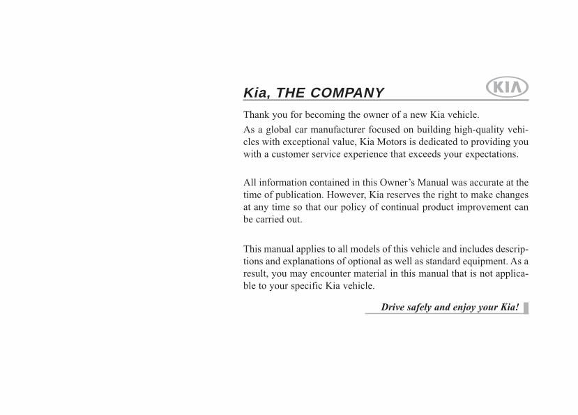
9. Door ......................................................4-19
10. Fuel filler lid ........................................4-34
11. Rear combination lamp.......................7-91
12. Tail gate ..............................................4-24
13. High mounted stop lamp ....................7-93
14. Rear window defroster......................4-102
15. Antenna ............................................4-147
16. Rearview camera................................4-88
OPS013002N
■ Rear view
❈ The actual shape may differ from the illustration.
Your vehicle at a glance
42
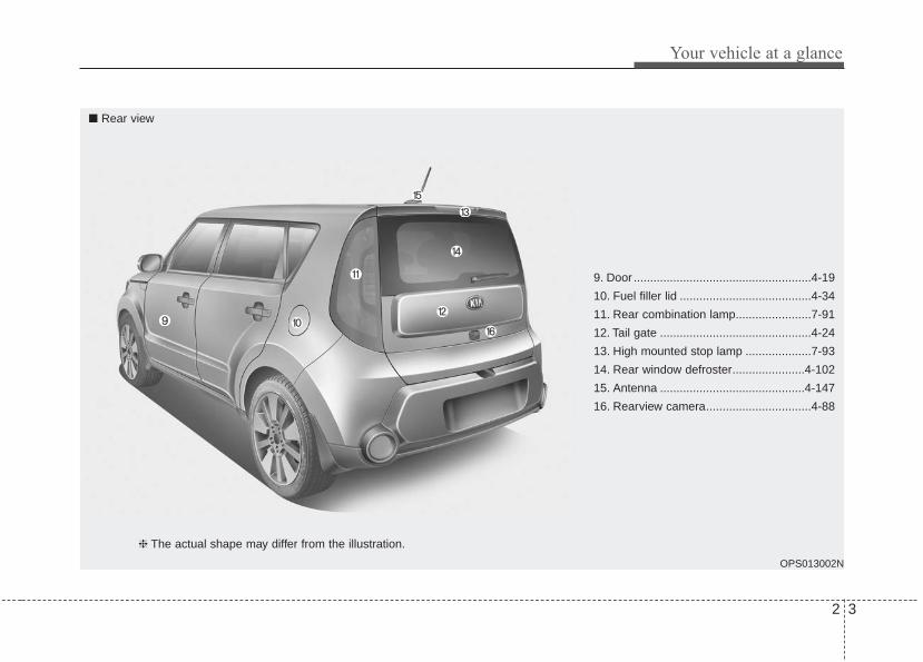
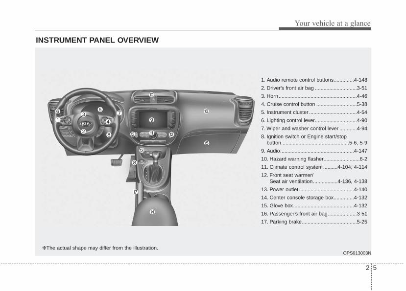
INTERIOR OVERVIEW
1. Inside door handle ................................4-19
2. Power window switch ............................4-27
3. Power window lock button.....................4-30
4. Central door lock switch........................4-21
5. Outside rearview mirror control.............4-51
6. Outside rearview mirror folding.............4-52
7. Fuel filler lid open lever .........................4-34
8. Instrument panel illumination controlswitch ...................................................4-55
9. LDWS On/Off button .............................5-48
10. Idle Stop and Go (ISG) OFF button....5-44
11. Steering wheel heater On/Off button ..4-45
12. ESC Off button....................................5-29
13. Advanced Lighting Speaker ..............4-150
14. Steering wheel ....................................4-43
15. Tilt and telescopic steering controllever.....................................................4-44
16. Inner fuse panel ..................................7-73
17. Hood release lever ..............................4-32
18. Seat.......................................................3-2
19. Transaxle shift lever ...................5-14, 5-17
OPS015004N❈ The actual shape may differ from the illustration.
2 5
Your vehicle at a glance
INSTRUMENT PANEL OVERVIEW
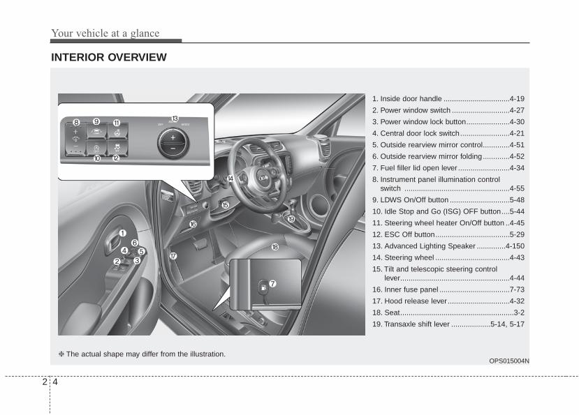
1. Audio remote control buttons..............4-148
2. Driver’s front air bag .............................3-51
3. Horn......................................................4-46
4. Cruise control button ............................5-38
5. Instrument cluster .................................4-54
6. Lighting control lever.............................4-90
7. Wiper and washer control lever ............4-94
8. Ignition switch or Engine start/stopbutton...............................................5-6, 5-9
9. Audio...................................................4-147
10. Hazard warning flasher.........................6-2
11. Climate control system..........4-104, 4-114
12. Front seat warmer/Seat air ventilation.................4-136, 4-138
13. Power outlet ......................................4-140
14. Center console storage box..............4-132
15. Glove box..........................................4-132
16. Passenger’s front air bag....................3-51
17. Parking brake......................................5-25
OPS013003N❈The actual shape may differ from the illustration.

Your vehicle at a glance
62
ENGINE COMPARTMENT
OPS073001
1. Windshield washer fluid reservoir .....7-43
2. Engine oil filler cap ...........................7-36
3. Engine oil dipstick .............................7-36
4. Engine coolant reservoir ...................7-39
5. Radiator cap .....................................7-40
6. Brake/clutch fluid reservoir ...............7-41
7. Positive battery terminal ...................7-53
8. Negative battery terminal..................7-53
9. Fuse box ...........................................7-74
10. Air cleaner.......................................7-45
* The actual engine compartment in the vehicle may differ from the illustration.
■■ 1.6L GDI

2 7
Your vehicle at a glance
OPS073002
* The actual engine room in the vehicle may differ from the illustration.
1. Windshield washer fluid reservoir .....7-43
2. Engine oil filler cap ...........................7-36
3. Engine oil dipstick .............................7-36
4. Engine coolant reservoir ...................7-39
5. Radiator cap .....................................7-40
6. Brake/clutch fluid reservoir ...............7-41
7. Positive battery terminal ...................7-53
8. Negative battery terminal..................7-53
9. Fuse box ...........................................7-74
10. Air cleaner.......................................7-45
■■ 2.0L GDI
Safety features of your vehicle
Seats . . . . . . . . . . . . . . . . . . . . . . . . . . . . . . . . . . . . . . 3-2• Front seat adjustment - Manual . . . . . . . . . . . . . . . . . 3-5• Front seat adjustment - Power. . . . . . . . . . . . . . . . . . . 3-6• Seatback pocket . . . . . . . . . . . . . . . . . . . . . . . . . . . . . . 3-11• Rear seat adjustment . . . . . . . . . . . . . . . . . . . . . . . . . 3-11
Seat belts . . . . . . . . . . . . . . . . . . . . . . . . . . . . . . . . . 3-16• Seat belt restraint system . . . . . . . . . . . . . . . . . . . . . . 3-16• Pre-tensioner seat belt . . . . . . . . . . . . . . . . . . . . . . . . 3-24• Seat belt precautions . . . . . . . . . . . . . . . . . . . . . . . . . . 3-26• Care of seat belts . . . . . . . . . . . . . . . . . . . . . . . . . . . . . 3-28
Child restraint system . . . . . . . . . . . . . . . . . . . . . . 3-30• Using a child restraint system . . . . . . . . . . . . . . . . . . 3-31• Tether anchor system . . . . . . . . . . . . . . . . . . . . . . . . . 3-35• Lower anchor system . . . . . . . . . . . . . . . . . . . . . . . . . 3-36
Air bag - advanced supplemental restraint system. . . . . . 3-39• How does the air bag system operate . . . . . . . . . . . . 3-40• Do not Installing a child restraint on a front
passenger's seat . . . . . . . . . . . . . . . . . . . . . . . . . . . . . 3-42
• Air bag warning light . . . . . . . . . . . . . . . . . . . . . . . . . 3-42• SRS components and functions . . . . . . . . . . . . . . . . . 3-43• Occupant Detection System (ODS) . . . . . . . . . . . . . . 3-46• Driver's and passenger's front air bag . . . . . . . . . . . 3-51• Side air bag . . . . . . . . . . . . . . . . . . . . . . . . . . . . . . . . . 3-54• Curtain air bag . . . . . . . . . . . . . . . . . . . . . . . . . . . . . . 3-56
• Inflation and non-inflation conditions of the air bag . . 3-57• SRS care . . . . . . . . . . . . . . . . . . . . . . . . . . . . . . . . . . . . 3-62• Additional safety precautions. . . . . . . . . . . . . . . . . . . 3-63• Adding equipment to or modifying your air bag-
equipped vehicle . . . . . . . . . . . . . . . . . . . . . . . . . . . . . 3-63• Air bag warning label . . . . . . . . . . . . . . . . . . . . . . . . . 3-63
3

Safety features of your vehicle
23
Front seat(1) Forward and backward(2) Seatback angle(3) Seat cushion height
(Driver’s seat)(4) Lumbar support (Driver’s seat)(5) Headrest
Rear seats(6) Seatback folding(7) Headrest
SEATS
OPS033001N
Manual seat
Power seat

3 3
Safety features of your vehicle
WARNING - Uprightingseat
Do not press the release leveron a manual seatback withoutholding and controlling theseatback. The seatback willspring upright possibly impact-ing you or other passengers.
WARNING - Loose objectsDo not place anything in the dri-ver's foot well or under the frontseats. Loose objects in the dri-ver's foot area could interferewith the operation of the footpedals.
WARNING- Driver responsibility for
passengers
The driver must advise the pas-senger to keep the seatback inan upright position wheneverthe vehicle is in motion. If a seatis reclined during an accident,the occupant's hips may slideunder the lap portion of the seatbelt, applying great force to theunprotected abdomen.
1KMN3662
WARNING- Seat cushionOccupants should never sit onaftermarket seat cushions or sit-ting cushions. The passenger'ships may slide under the lapportion of the seat belt duringan accident or a sudden stop.
WARNING - Driver’s seat• Never attempt to adjust the
seat while the vehicle is mov-ing. This could result in lossof control of your vehicle.
• Do not allow anything to inter-fere with the normal position ofthe seatback and seatbackadjustment.
• Sit as far back as possiblefrom the steering wheel whilestill maintaining comfortablecontrol of your vehicle. A dis-tance of at least 10" from yourchest to the steering wheel isrecommended. Failure to doso could result in air bag infla-tion injuries to the driver.

Safety features of your vehicle
43
WARNING - UnexpectedSeat Movement
After adjusting a manual seat,always check that it is locked byshifting your weight to the frontand back. Sudden or unexpect-ed movement of the driver'sseat could cause you to losecontrol of the vehicle.
WARNING - Luggage andCargo
Do not stack pile or stack luggageor cargo higher than the seatbackin the cargo area. In an accidentthe cargo could strike and injury apassenger. If objects are large,heavy or must be piled, they mustbe secured in the cargo area.
WARNING - Seat adjust-ment
• Do not adjust the seat whilewearing seat belts. Moving theseat forward will cause strongpressure on the abdomen.
• Do not place your hand nearthe seat bottom or seat trackwhile adjusting the seat. Yourhand could get caught in theseat mechanism.
WARNING - Small ObjectsUse extreme caution when pick-ing up small objects trappedunder the seats or between theseat and the center console.Your hands might be cut orinjured by the sharp edges ofthe seats mechanism.
WARNING - Cargo AreaDo not allow passengers to ridein the cargo area under any cir-cumstance. The cargo area issolely for the purpose of trans-porting luggage or cargo.
WARNING - Rear seat-backs
Always lock the rear seatbackbefore driving. Failure to do socould result in passengers orobjects being thrown forwardinjuring vehicle occupants.

3 5
Safety features of your vehicle
Front seat adjustment - manualForward and backward
To move the seat forward or backward:1. Pull the seat slide adjustment
lever up and hold it.2. Slide the seat to the position you
desire.3. Release the lever and make sure
the seat is locked in place.Adjust the seat before driving, andmake sure the seat is locked securelyby trying to move forward and back-ward without using the lever. If theseat moves, it is not locked properly.
Seatback angle
To recline the seatback:1. Lean forward slightly and lift up the
seatback recline lever.2. Carefully lean back on the seat
and adjust the seatback of theseat to the position you desire.
3. Release the lever and make surethe seatback is locked in place.(The lever MUST return to its orig-inal position for the seatback tolock.)
Seat height (for driver’s seat)
To change the height of the seat,push the lever upwards or down-wards.• To lower the seat cushion, push the
lever down several times.• To raise the seat cushion, pull the
lever up several times.
OPS033002
OPS033003 OPS033004

Safety features of your vehicle
63
Front seat adjustment - power (if equipped)The front seat can be adjusted byusing the control switches located onthe outside of the seat cushion.Before driving, adjust the seat to theproper position so you can easily con-trol the steering wheel, pedals andswitches on the instrument panel.
When in operation, the power seatconsumes a large amount of electri-cal power. To prevent unnecessarycharging system drain, don’t adjustthe power seat longer than neces-sary while the engine is not running.
Forward and backward
Push the control switch forward orbackward to move the seat to thedesired position. Release the switchonce the seat reaches the desiredposition.
OPS033005
CAUTION - Power seatadjustments
The power seating controlsfunction by electronic motor.Excessive operation may causedamage to the electrical equip-ment.
CAUTION - Power SeatingDo not operate two or morepower seat control switches atthe same time. Doing so maydamage the power seat motor orelectrical components.
WARNING - Unattendedchildren
Do not leave children unattend-ed in the vehicle. Children mightoperate features of the vehiclethat could injure them.

3 7
Safety features of your vehicle
Seatback angle
Push the control switch forward orbackward to move the seatback tothe desired angle. Release theswitch once the seat reaches thedesired position.
Seat height (for driver’s seat)
Pull the front portion of the controlswitch up to raise or press down tolower the front part of the seat cush-ion. Pull the rear portion of the con-trol switch up to raise or press downto lower the rear part of the seatcushion. Release the switch once theseat reaches the desired position.
Lumbar support (for driver’s seat)
The depth of the lumbar support canbe adjusted by pressing the buttonfore and after. If equipped, the loca-tion of the lumbar support can beadjusted up and down by pressingthe button up and down.
OPS033006 OPS033007 OPS033008
Safety features of your vehicle
83
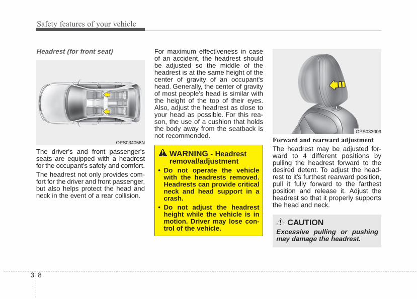
Headrest (for front seat)
The driver's and front passenger'sseats are equipped with a headrestfor the occupant's safety and comfort.The headrest not only provides com-fort for the driver and front passenger,but also helps protect the head andneck in the event of a rear collision.
For maximum effectiveness in caseof an accident, the headrest shouldbe adjusted so the middle of theheadrest is at the same height of thecenter of gravity of an occupant'shead. Generally, the center of gravityof most people's head is similar withthe height of the top of their eyes.Also, adjust the headrest as close toyour head as possible. For this rea-son, the use of a cushion that holdsthe body away from the seatback isnot recommended.
Forward and rearward adjustment
The headrest may be adjusted for-ward to 4 different positions bypulling the headrest forward to thedesired detent. To adjust the head-rest to it’s furthest rearward position,pull it fully forward to the farthestposition and release it. Adjust theheadrest so that it properly supportsthe head and neck.
OPS034058N
OPS033009
WARNING - Headrestremoval/adjustment
• Do not operate the vehiclewith the headrests removed.Headrests can provide criticalneck and head support in acrash.
• Do not adjust the headrestheight while the vehicle is inmotion. Driver may lose con-trol of the vehicle.
CAUTIONExcessive pulling or pushingmay damage the headrest.

3 9
Safety features of your vehicle
Adjusting the height up and down
To raise the headrest, pull it up to thedesired position (1). To lower theheadrest, push and hold the releasebutton (2) on the headrest supportand lower the headrest to the desiredposition (3).
✽✽ NOTICEIf you recline the seatback towardsthe front with the headrest and seatcushion raised, the headrest maycome in contact with the sunvisor orother parts of the vehicle.
Removal/Reinstall
To remove the headrest:1. Recline the seatback(2) with the
recline lever or switch(1).2. Raise headrest as far as it can go.3. Press the headrest release button
(3) while pulling the headrest up (4).
OPS033010 OYFH034205
OPS033047L
OPS033049L
■ Type A
■ Type B

Safety features of your vehicle
103
To reinstall the headrest :1. Put the headrest poles (2) into the
holes while pressing the releasebutton (1).
2. Recline the seatback(4) with therecline lever or switch(3)
3. Adjust the headrest to the appropri-ate height.
WARNINGNEVER allow anyone to ride in aseat with the headrest removed.
OPS033048L
OPS033050L
■ Type A
■ Type B
WARNING - HeadrestReinstallation
To reduce the risk of injury tothe head or neck, always makesure the headrest is locked intoposition and adjusted properlyafter reinstalling.

3 11
Safety features of your vehicle
Seatback pocket (if equipped)
The seatback pocket is provided onthe back of the front passenger’sseatbacks.
Rear seat adjustmentFolding the rear seatThe rear seatbacks can be folded tofacilitate carrying long items or toincrease the luggage capacity of thevehicle.
To fold down the rear seatback
1. Insert the rear seat belt buckle inthe pocket (if equipped) betweenthe rear seatback and cushion,and insert the rear seat belt web-bing in the guide to prevent theseat belt from being damaged.
OPS033016
WARNING - Folded downseatback
Never allow passengers sit on topof the folded down seatback whilethe vehicle is moving.This is not aproper seating position and noseat belts are available for use.This could result in serious injuryor death in case of an accident orsudden stop.
WARNING - ObjectsObjects carried on the foldeddown seatback should notextend higher than the top ofthe front seatbacks. This couldallow cargo to slide forward andcause injury or damage duringsudden stops.
WARNING - Seatbackpockets
Do not put heavy or sharpobjects in the seatback pocket.An occupant could contact suchobjects in a crash. Heavy objectsin the front passenger seatbackcould also interfere with theairbag sensing system.
OPS033017
OPS033015

Safety features of your vehicle
123
2. Set the front seatback to theupright position and if necessary,slide the front seat forward.
3. Lower the rear headrests to thelowest position.
4.Pull on the seatback folding lever,then fold the seat toward the frontof the vehicle. When you return theseatback to its upright position,always be sure it has locked intoposition by pushing on the top ofthe seatback.
5.To use the rear seat, lift and pullthe seatback backward by pullingon the folding lever.Pull the seatback firmly until itclicks into place.Make sure the seatback is lockedin place.
6.Return the rear seat belt to theproper position.
OPS033018
WARNING - CargoDo not place heavy objects inthe rear seats, since they can-not be properly secured andmay hit vehicle occupants in afrontal collision.

3 13
Safety features of your vehicle
Make sure the engine is off, theautomatic transaxle is in P (Park) orthe manual transaxle is in R(Reverse) or 1st, and the parkingbrake is securely applied wheneverloading or unloading cargo. Failure totake these steps may allow the vehi-cle to move if the shift lever is inad-vertently moved to another position.
Headrest
The rear seat(s) is equipped withheadrests in all the seating positionsfor the occupant's safety and comfort.The headrest not only provides com-fort for passengers, but also helpsprotect the head and neck in theevent of a collision.
For maximum effectiveness in case ofan accident, the headrest should beadjusted so the middle of the head-rest is at the same height as the cen-ter of gravity of an occupant's head.Generally, the center of gravity ofmost people's head is similar withthe height of the top of their eyes.Also adjust the headrest as close toyour head as possible. For this rea-son, the use of a cushion that holdsthe body away from the seatback isnot recommended.
OPA039053
**
WARNING - Headrestremoval/adjustment
Do not operate the vehicle withthe headrests removed.Headrests can provide criticalneck and head support in acrash.

Safety features of your vehicle
143
Adjusting the height up and down
To raise the headrest :1. Pull it up to the desired position (1).
To lower the headrest :1. Push and hold the release button
(2) on the headrest support2. Lower the headrest to the desired
position (3).
Removal and installation
To remove the headrest :1. Raise it as far as it can go then
press the release button (1) whilepulling the headrest up (2).
To reinstall the headrest :1. Put the headrest poles (3) into the
holes while pressing the releasebutton (1).
2. Adjust it to the appropriate height.
Make sure the headrest locks inposition after adjusting it to properlyprotect the occupants.
OPS033034
WARNING - Headrestinstallation
After installing the headrest,make sure that it is installed inthe right direction.A headrest installed reverselycould increase whiplash injuryduring rear impact.
OPS033033

3 15
Safety features of your vehicle
Armrest
To use the armrest, pull it forwardfrom the seatback.
OPS033032
Safety features of your vehicle
163
SEAT BELTSSeat belt restraint systemSeat belts are designed to bear uponthe bony structure of the body, andshould be worn low across the frontof the pelvis, chest and shoulders, asapplicable; wearing the lap section ofthe belt across the abdominal areamust be avoided.Seat belts should be adjusted asfirmly as possible, consistent withcomfort, to provide the protection forwhich they have been designed.A slack belt will greatly reduce theprotection afforded to the wearer.Care should be taken to avoid con-tamination of the webbing with pol-ishes, oils and chemicals, and partic-ularly battery acid. Cleaning maysafely be carried out using mild soapand water. The belt should bereplaced if webbing becomes frayed,contaminated or damaged.
• For maximum restraint system pro-tection, the seat belts must alwaysbe used whenever the vehicle ismoving. A properly positionedshoulder belt should be positionedmidway over your shoulder acrossyour collarbone.
• Never allow children to ride in thefront passenger seat. See childrestraint system section for furtherdiscussion.
WARNING - Shoulder Belt• Never wear the shoulder belt
under your arm or behindyour back. An improperlypositioned shoulder belt can-not protect the occupant in acrash.
• Always wear both the shoul-der portion and lap portion ofthe lap/shoulder belt.
WARNING - Damagedseat belt
Replace the entire seat beltassembly if any part of the web-bing or hardware is damaged asyou can no longer be sure that adamaged seat belt will provideprotection in a crash.

3 17
Safety features of your vehicle
• No modifications or additionsshould be made by the user whichwill either prevent the seat beltadjusting devices from operating toremove slack, or prevent the seatbelt assembly from being adjustedto remove slack.
• When you fasten the seat belt, becareful not to latch the seat belt inbuckles of other seat. It's very dan-gerous and you may not be pro-tected by the seat belt properly.
• Do not unfasten the seat belt anddo not fasten and unfasten the seatbelt repeatedly while driving. Thiscould result in loss of control, andan accident causing death, seriousinjury, or property damage.
• When fastening the seat belt,make sure that the seat belt doesnot pass over objects that are hardor can break easily.
Seat belt warning (for driver’s seat)
The driver's seat belt warning lightand chime will activate pursuant tothe following table when the ignitionswitch is in "ON" position.
1GQA2083
WARNING - Seat beltbuckle
Do not allow foreign material(gum, crumbs, coins, etc.) toobstruct the seat belt buckle.This may prevent the seat beltfrom fastening securely.

Safety features of your vehicle
183
*1 Warning pattern repeats 11 times withan interval of 24 seconds. If the driver'sseat belt is buckled, the light will stopwithin 6 seconds and chime will stopimmediately.
*2 The light will stop within 6 seconds andchime will stop immediately.
Seat belt - Driver's 3-point systemwith emergency locking retractor
To fasten your seat belt:
To fasten your seat belt, pull it out ofthe retractor and insert the metal tab(1) into the buckle (2). There will bean audible "click" when the tab locksinto the buckle.
The seat belt automatically adjusts tothe proper length only after the lapbelt portion is adjusted manually sothat it fits snugly around your hips. Ifyou lean forward in a slow, easymotion, the belt will extend and letyou move around. If there is a sud-den stop or impact, however, the beltwill lock into position. It will also lockif you try to lean forward too quickly.If you are not able to pull out the seatbelt from the retractor, firmly pull thebelt out and release it. Then you willbe able to pull the belt out smoothly.
B180A01NF-1
Conditions Warning Pattern
Seat BeltVehicle
SpeedLight-Blink
Chime-
Sound
Unbuckled 6 seconds
Buckled 6 seconds None
Buckled →Unbuckled
Below 5 km/h
(3 mph)6 seconds None
5 km/h~
10 km/h6 seconds
Above 10 km/h
(6 mph)
6 sec. on / 24 sec. off
(11 times)
Unbuckled
Above 10 km/h
(6 mph)
↓
Below 5 km/h
(3 mph)
6 seconds *1
↓
Stop *2

3 19
Safety features of your vehicle
Height adjustment
You can adjust the height of the shoul-der belt anchor to one of the 3 posi-tions for maximum comfort and safety.The height of the adjusting seat beltshould not be too close to your neck.The shoulder portion should beadjusted so that it lies across yourchest and midway over your shouldernear the door and not your neck.To adjust the height of the seat beltanchor, lower or raise the heightadjuster into an appropriate position.To raise the height adjuster, pull it up(1). To lower it, push it down (3) whilepressing the height adjuster button (2).
Release the button to lock theanchor into position. Try sliding theheight adjuster to make sure that ithas locked into position.
You should place the lap belt portionas low as possible and snugly acrossyour hips, not on your waist. If the lapbelt is located too high on your waist,it may increase the chance of injuryin the event of a collision. Both armsshould not be under or over the belt.Rather, one should be over and theother under, as shown in the illustra-tion.Never wear the seat belt under thearm that is near the door.
B200A02NFOXM039026
Front seat
WARNING - Shoulder beltpositioning
Never position the shoulder beltacross your neck or face.
WARNING - Seat beltreplacement
Replace your seat belts afterbeing in an accident. Failure toreplace seat belts after an acci-dent could leave you with dam-aged seat belts that will not pro-vide protection in the event ofanother collision.

Safety features of your vehicle
203
Seat belts - Front passenger andrear seat 3-point system withcombination locking retractorTo fasten your seat belt:
Combination retractor type seat beltsare installed in the rear seat posi-tions to help accommodate theinstallation of child restraint systems.Although a combination retractor isalso installed in the front passengerseat position, it is strongly recom-mended that children always beseated in the rear seat. NEVERplace any infant restraint system inthe front seat of the vehicle.This type of seat belt combines thefeatures of both an emergency lock-ing retractor seat belt and an auto-matic locking retractor seat belt. Tofasten your seat belt, pull it out of theretractor and insert the metal tab intothe buckle. There will be an audible"click" when the tab locks into thebuckle. When not securing a childrestraint, the seat belt operates in thesame way as the driver's seat belt(Emergency Locking Retractor Type).
It automatically adjusts to the properlength only after the lap belt portionof the seat belt is adjusted manuallyso that it fits snugly around your hips.When the seat belt is fully extendedfrom the retractor to allow the instal-lation of a child restraint system, theseat belt operation changes to allowthe belt to retract, but not to extend(Automatic Locking Retractor Type).Refer to “Using a child restraint sys-tem” in this section.
✽✽ NOTICEAlthough the combination retractorprovides the same level of protectionfor seated passengers in either emer-gency or automatic locking modes,have the seated passengers use theemergency locking feature forimproved convenience. The auto-matic locking function is intended tofacilitate child restraint installation.To convert from the automatic lock-ing feature to the emergency lockingoperation mode, allow the unbuck-led seat belt to fully retract.
Do NOT fold down the left portion ofthe rear seat back when the rearcenter seat belt is buckled. ALWAYSUNBUCKLE the rear center seat beltbefore folding down the left portion ofthe rear seat back. If the rear centerseat belt is buckled when the left por-tion of the rear seat back is foldeddown, distortion and damage to thetop portion of the seat back and seatbelt garnish may result, causing theseat back to lock into the foldeddown position.

3 21
Safety features of your vehicle
To release the seat belt:
The seat belt is released by pressingthe release button (1) on the lockingbuckle. When it is released, the beltshould automatically draw back intothe retractor.If this does not happen, check thebelt to be sure it is not twisted, thentry again.
Stowing the rear seat belt
The rear seat belt buckles can bestowed in the pocket between therear seatback and cushion when notin use.
Routing the seat belt webbingthrough the rear seat belt guides willhelp keep the belts from beingtrapped behind or under the seats.After inserting the seat belt, tightenthe belt webbing by pulling it up.
CAUTION - Seat beltguide
Remove the seat belt from theguides before using. If you pullon the seat belt when it is storedin the guides, it may damage theguides and/or belt webbing.
B210A01NF-1
OPS033017
OPS033015

Safety features of your vehicle
223
3 Point rear center belt
To fasten the rear center belt
1.Insert the mini tongue (A) into theopen end of the anchor connector(C) until an audible “click" is heard,indicating the latch is locked. Makesure the belt is not twisted.
2.Pull the tongue plate (B) and insertthe tongue plate (B) into the openend of the buckle (D) until an audi-ble “click” is heard, indicating thelatch is locked. Make sure the beltis not twisted.When using the rear center seatbelt, the buckle with the “CENTER”mark must be used.
ORP032073C
ORP032074
WARNING - Rear centerseat belt
Do not separate mini tongue andmini buckle even if there is notan occupant.If it is separated, It may hit therear seat occupants in a collisionor sudden stops.
3 23
Safety features of your vehicle
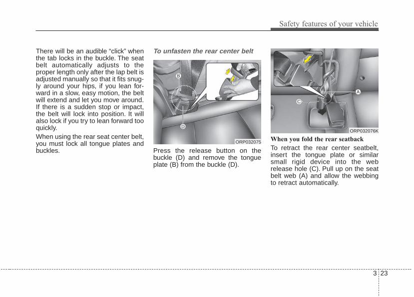
There will be an audible “click” whenthe tab locks in the buckle. The seatbelt automatically adjusts to theproper length only after the lap belt isadjusted manually so that it fits snug-ly around your hips, if you lean for-ward in a slow, easy motion, the beltwill extend and let you move around.If there is a sudden stop or impact,the belt will lock into position. It willalso lock if you try to lean forward tooquickly.When using the rear seat center belt,you must lock all tongue plates andbuckles.
To unfasten the rear center belt
Press the release button on thebuckle (D) and remove the tongueplate (B) from the buckle (D).
When you fold the rear seatback
To retract the rear center seatbelt,insert the tongue plate or similarsmall rigid device into the webrelease hole (C). Pull up on the seatbelt web (A) and allow the webbingto retract automatically.
ORP032075
ORP032076K
Safety features of your vehicle
243
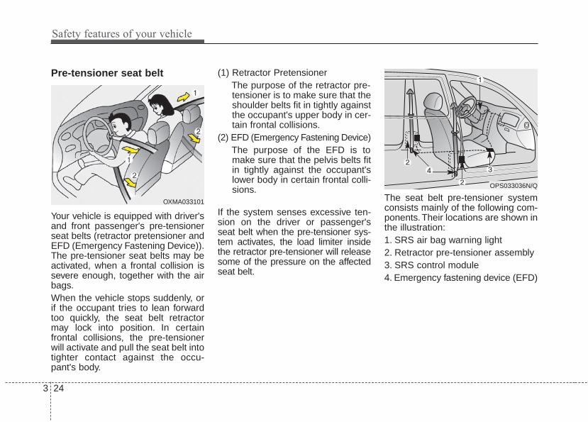
Pre-tensioner seat belt
Your vehicle is equipped with driver'sand front passenger's pre-tensionerseat belts (retractor pretensioner andEFD (Emergency Fastening Device)).The pre-tensioner seat belts may beactivated, when a frontal collision issevere enough, together with the airbags.When the vehicle stops suddenly, orif the occupant tries to lean forwardtoo quickly, the seat belt retractormay lock into position. In certainfrontal collisions, the pre-tensionerwill activate and pull the seat belt intotighter contact against the occu-pant's body.
(1) Retractor PretensionerThe purpose of the retractor pre-tensioner is to make sure that theshoulder belts fit in tightly againstthe occupant's upper body in cer-tain frontal collisions.
(2) EFD (Emergency Fastening Device)The purpose of the EFD is tomake sure that the pelvis belts fitin tightly against the occupant'slower body in certain frontal colli-sions.
If the system senses excessive ten-sion on the driver or passenger'sseat belt when the pre-tensioner sys-tem activates, the load limiter insidethe retractor pre-tensioner will releasesome of the pressure on the affectedseat belt.
The seat belt pre-tensioner systemconsists mainly of the following com-ponents.Their locations are shown inthe illustration:1. SRS air bag warning light2. Retractor pre-tensioner assembly3. SRS control module4. Emergency fastening device (EFD)
OPS033036N/Q
OXMA033101

3 25
Safety features of your vehicle
✽✽ NOTICEWhen the pre-tensioner seat beltsare activated, a loud noise may beheard and fine dust, which mayappear to be smoke, may be visiblein the passenger compartment.These are normal operating condi-tions and are not hazardous.
• Both the driver's and front passen-ger's seat belt pre-tensioner sys-tem may be activated not only incertain frontal collision but also incertain side collision or rollover, ifthe vehicle is equipped with a sideor curtain air bag.
• Because the sensor that activatesthe SRS air bag is connected withthe pre-tensioner seat belt, theSRS air bag warning light onthe instrument panel will illuminatefor approximately 6 seconds afterthe ignition switch has been turnedto the ON position, and then itshould turn off.
If the pre-tensioner seat belt systemare not working properly, this warn-ing light will illuminate even if there isno malfunction of the SRS air bag. Ifthe SRS air bag warning light doesnot illuminate when the ignitionswitch is turned ON, or if it remainsilluminated after illuminating forapproximately 6 seconds, or if it illu-minates while the vehicle is beingdriven, have an authorized KiaPremium dealer inspect the pre-ten-sioner seat belt and SRS air bag sys-tem as soon as possible.
• Pre-tensioners are designed tooperate only one time. After activa-tion, pre-tensioner seat belts mustbe replaced. All seat belts, of anytype, should always be replacedafter they have been worn during acollision.
• Do not strike the pre-tensioner seatbelt assemblies.
WARNING - Skin irritationWash all exposed skin areasthoroughly after an accident inwhich the pre-tensioner seatbelts were activated. The finedust from the pre-tensioneractivation may cause skin irrita-tion and should not be breathedfor prolonged periods.

Safety features of your vehicle
263
Seat belt precautionsInfant or small childChild and/or infant seats must beproperly placed and installed in therear seat. For more informationabout the use of these restraints,refer to “Child restraint system” in thissection.
✽✽ NOTICESmall children are best protectedfrom injury in an accident whenproperly restrained in the rear seatby a child restraint system thatmeets the requirements of the safetystandards of your country. Beforebuying any child restraint system,make sure that it has a label certify-ing that it meets safety standards ofyour country. The restraint must beappropriate for your child's heightand weight. Check the label on thechild restraint for this information.Refer to “Child restraint system” inthis chapter.
WARNING - Hot pre-tesioner
Do not touch the pre-tensionerseat belt assemblies for severalminutes after they have beenactivated. When the pre-ten-sioner seat belt mechanismfires during a collision the pre-tensioner becomes hot and canburn you.

3 27
Safety features of your vehicle
Larger childrenChildren who are too large for childrestraint systems should alwaysoccupy the rear seat and use theavailable lap/shoulder belts. The lapportion should be fastened andsnugged on the hips and as low aspossible. Check if the belt fits period-ically. A child's squirming could putthe belt out of position. Children aregiven the most safety in the event ofan accident when they are restrainedby a proper restraint system in therear seat. If a larger child (over age12) must be seated in the front seat,the child should be securelyrestrained by the available lap/shoul-der belt and the seat should beplaced in the rearmost position.Children age 12 and under should berestrained securely in the rear seat.NEVER place a child age 12 andunder in the front seat. NEVER placea rear facing child seat in the frontseat of a vehicle.
If the shoulder belt portion slightlytouches the child’s neck or face, tryplacing the child closer to the center ofthe vehicle. If the shoulder belt stilltouches their face or neck they need tobe returned to a child restraint system.
Restraint of pregnant women Pregnant women should wearlap/shoulder belt assemblies when-ever possible according to specificrecommendations by their doctors.The lap portion of the belt should beworn AS SECURELY AND LOW ASPOSSIBLE.WARNING - Small
childrenDo not allow small children toride in the vehicle without anappropriate child restraint sys-tem. If the shoulder belt comesin contact with your child's neckor face your child is too small toride in the vehicle. In a crash theseat belt will inflict injury to yourchild's neck, throat and face.
WARNING - Pregnantwomen
Pregnant women must neverplace the lap portion of the seatbelt above or on the abdomenwhere the fetus is located. Theforce of the seat belt during acollision will crush the fetus.

Safety features of your vehicle
283
Injured personA seat belt should be used when aninjured person is being transported.When this is necessary, you shouldconsult a physician for recommenda-tions.
One person per beltTwo people (including children)should never attempt to use a singleseat belt. This could increase theseverity of injuries in case of an acci-dent.
Do not lie downTo reduce the chance of injuries inthe event of an accident and toachieve maximum effectiveness ofthe restraint system, all passengersshould be sitting up and the front andrear seats should be in an uprightposition when the vehicle is moving.A seat belt cannot provide properprotection if the person is lying downin the rear seat or if the front and rearseats are in a reclined position.
Care of seat beltsSeat belt systems should never bedisassembled or modified. In addi-tion, care should be taken to assurethat seat belts and belt hardware arenot damaged by seat hinges, doorsor other abuse.
WARNING - Pinchedseat belt
Make sure that the webbingand/or buckle does not getcaught or pinched in the rearseat when returning the rearseatback to its upright position.A caught or pinchedwebbing/buckle may becomedamaged and could fail during acollision or sudden stop.

3 29
Safety features of your vehicle
Periodic inspectionAll seat belts should be inspectedperiodically for wear or damage ofany kind. Any damaged parts shouldbe replaced as soon as possible.
Keep belts clean and drySeat belts should be kept clean anddry. If belts become dirty, they can becleaned by using a mild soap solu-tion and warm water. Bleach, dye,strong detergents or abrasivesshould not be used because theymay damage and weaken the fabric.
When to replace seat beltsThe entire in-use seat belt assemblyor assemblies should be replaced ifthe vehicle has been involved in anaccident. This should be done even ifno damage is visible. Additionalquestions concerning seat belt oper-ation should be directed to anauthorized Kia dealer.

Safety features of your vehicle
303
CHILD RESTRAINT SYSTEMChildren riding in the vehicle shouldsit in the rear seat and must alwaysbe properly restrained to minimizethe risk of injury in an accident, sud-den stop or sudden maneuver.According to accident statistics, chil-dren are safer when properlyrestrained in the rear seats than inthe front seat. Larger children not ina child restraint should use one ofthe seat belts provided.You should be aware of the specificrequirements in your country. Childand/or infant safety seats must beproperly placed and installed in therear seat. You must use a commer-cially available child restraint systemthat meets the requirements of theSafety Standards of your country.Child restraint systems are designedto be secured in vehicle seats by thelap belt portion of a lap/shoulder belt,or by a tether anchor and/or LATCHanchors (if equipped).
Children could be injured or killed ina crash if their restraints are notproperly secured. For small childrenand babies, a child seat or infant seatmust be used. Before buying a par-ticular child restraint system, makesure it fits your vehicle seat and seatbelts, and fits your child.Follow all the instructions providedby the manufacturer when installingthe child restraint system.
When the child restraint system is notin use, store it in the luggage area orfasten it with a seat belt so that it willnot be thrown forward in case of asudden stop or an accident.
WARNING - Restraintlocation
Never install a child or infantseat on the front passenger'sseat. A child riding in the frontpassenger seat can be forceful-ly struck by an inflating airbag.
WARNING- Hot childrestraint
A child restraint system canbecome very hot if it is left in aclosed vehicle on a sunny day. Besure to check the seat cover,buckles and latches before plac-ing a child in the restraint system.

3 31
Safety features of your vehicle
After an accident, have an author-ized Kia dealer check the childrestraint system, seat belt, tetheranchor and lower anchor.
Using a child restraint system
For small children and babies, theuse of a child seat or infant seat isrequired. The child seat or infant seatshould be of appropriate size for thechild and should be installed inaccordance with the manufacturer'sinstructions.
WARNING- Holding children
Never hold a child in your armsor lap when riding in a vehicle.The violent forces created dur-ing a crash will tear the childfrom your arms and throw thechild against the car’s interior.Always use a child restraintsystem which is appropriate foryour child's height and weight.
WARNING - UnattendedChildren
Never leave children unattendedin a vehicle. The car can heat upvery quickly, resulting in injuriesto the child in the vehicle.
WARNING - Seat belt useDo not use one seat belt for twooccupants at the same time.This will eliminate any safetybenefit provided by the seat beltto the occupants.
CRS09
OUN026150
Forward-facing child restraint system
Rearward-facing child restraint system

Safety features of your vehicle
323
For safety reasons, we recommendthat the child restraint system beused in the rear seats.Never place a rear-facing childrestraint in the front passenger seat,because of the danger an inflatingpassenger-side air bag could impactthe rear-facing child restraint and killthe child.Since all passenger seat belts movefreely under normal conditions andonly lock under extreme or emer-gency conditions (emergency lockmode), you must manually changethese seat belts to the auto lockmode to secure a child restraint.If the seat belt does not operate asdescribed in this section, have thesystem checked immediately by yourauthorized Kia dealer. ✽✽ NOTICE
If the vehicle headrest preventsproper installation of a child seat (asdescribed in the child seat systemmanual), the headrest of the respec-tive seating position shall be read-justed or entirely removed.
Placing a passenger seat beltinto the auto lock mode
The auto lock mode will help preventthe normal movement of the child inthe vehicle from causing the seat beltto loosen and compromise the childrestraint system. To secure a childrestraint system, use the followingprocedure.
E2MS103005
WARNING - Child seatinstallation
• Always follow the instructionsprovided by the child restraintsystem manufacturer. Childrestraint system manufactur-ers know their products best.
• Failure to observe this manu-al's instructions regardingchild restraint system and theinstructions provided with thechild restraint system couldresult in the improper installa-tion of the child restraint sys-tem which may reduce theprotection to your child in acrash or a sudden stop.

3 33
Safety features of your vehicle
To install a child restraint system onthe outboard or center rear seats, dothe following:1. Place the child restraint system in
the seat and route the lap/shoul-der belt around or through therestraint, following the restraintmanufacturer’s instructions. Besure the seat belt webbing is nottwisted.
2. Fasten the lap/shoulder belt latchinto the buckle. Listen for the dis-tinct “click” sound.
Position the release button so that itis easy to access in case of an emer-gency.
3. Pull the shoulder portion of theseat belt all the way out. When theshoulder portion of the seat belt isfully extended, it will shift theretractor to the “Auto Lock” (childrestraint) mode.
4. Slowly allow the shoulder portionof the seat belt to retract and listenfor an audible “clicking” or “ratchet-ing” sound. This indicates that theretractor is in the “Auto Lock”mode. If no distinct sound isheard, repeat steps 3 and 4.
OEN036101 OEN036102 OEN036103

Safety features of your vehicle
343
5. Remove as much slack from thebelt as possible by pushing downon the child restraint system whilefeeding the shoulder belt back intothe retractor.
6. Push and pull on the child restraintsystem to confirm that the seatbelt is holding it firmly in place. If itis not, release the seat belt andrepeat steps 2 through 6.
7. Double check that the retractor isin the “Auto Lock” mode byattempting to pull more of the seatbelt out of the retractor. If you can-not, the retractor is in the “AutoLock” mode.
The lap/shoulder belt automaticallyreturns to the “emergency lockmode” whenever the belt is allowedto retract fully. Therefore, the preced-ing seven steps must be followedeach time a child restraint isinstalled.To remove the child restraint, pressthe release button on the buckle andthen pull the lap/shoulder belt out ofthe restraint and allow the seat beltto retract fully.
When the seat belt is allowed toretract to its fully stowed position,the retractor will automaticallyswitch from the “Auto Lock” modeto the emergency lock mode fornormal adult usage.
OEN036104
WARNING - Auto lockmode
Set the retractor to AutomaticLock mode when installing anychild restraint system. If theretractor is not in the AutomaticLocking mode, the childrestraint can move when yourvehicle turns or stops suddenly.

3 35
Safety features of your vehicle
Securing a child restraint seatwith tether anchor system
Child restraint hook holders arelocated on the back of the rear seat-backs.
This symbol indicates theposition of the tether anchor.
1. Route the child restraint seat strapover the seatback.For vehicles with adjustable head-rests, route the tether strap underthe headrest and between theheadrest posts, otherwise routethe tether strap over the top of theseatback. In case of interferencebetween the child restraint seatand the headrest remove the par-ticular head restraint for better fit-ment of the child restraint seat.
2. Connect the tether strap hook tothe appropriate child restrainthook holder and tighten to securethe child restraint seat.
OXM039034N
OPS033019
WARNING - Tether strapNever mount more than onechild restraint to a single tetheror to a single lower anchoragepoint. The increased loadcaused by multiple seats maycause the tethers or anchoragepoints to break.

Safety features of your vehicle
363
Check that the child restraint systemis secure by pushing and pulling it indifferent directions. Incorrectly fittedchild restraints may swing, twist, tipor separate causing death or seriousinjury.
Securing a child restraint seat withchild seat lower anchor system
Some child seat manufacturersmake child restraint seats that arelabeled as LATCH or LATCH-com-patible child restraint seats. LATCHstands for "Lower Anchors andTethers for Children". These seatsinclude two rigid or webbing mount-ed attachments that connect to twoLATCH anchors at specific seatingpositions in your vehicle. This type ofchild restraint seat eliminates theneed to use seat belts to attach thechild seat in the rear seats.
Child restraint symbols are locatedon the left and right 2nd row seatbacks to indicate the position of thelower anchors for child restraints.
OXM039060N
Lower Anchor
Lower AnchorPosition Indicator
OPS034059N

3 37
Safety features of your vehicle
Install the child restraint seat fullyrearward against the seatback withthe seatback reclined two positionsfrom the most upright latched posi-tion.
LATCH anchors have been providedin your vehicle. The LATCH anchorsare located in the left and right out-board rear seating positions. Theirlocations are shown in the illustra-tion. There is no LATCH anchor pro-vided for the center rear seatingposition.The LATCH anchors are locatedbetween the seatback and the seatcushion of the 2nd row seat left andright outboard seating positions.Follow the child seat manufacturer’sinstructions to properly install childrestraint seats with LATCH orLATCH-compatible attachments.
WARNING - Unused rearseatbelts
Always fasten the seatbeltsbehind the child restraint seatwhen they are not used tosecure the child seat. Failure todo so may result in child stran-gulation.
OXM039036N
Safety features of your vehicle
383
Once you have installed the LATCHchild restraint, assure that the seat isproperly attached to the LATCH andtether anchors.Also, test the child restraint seatbefore you place the child in it. Tiltthe seat from side to side. Also try totug the seat forward. Check to see ifthe anchors hold the seat in place.
WARNING - LATCH loweranchors
Never attempt to attach aLATCH equipped seat in thecenter seating position. LATCHlower anchors are only to beused with the left and right rearoutboard seating positions. Youmay damage the anchors or theanchors may fail and break in acollision.
3 39
Safety features of your vehicle
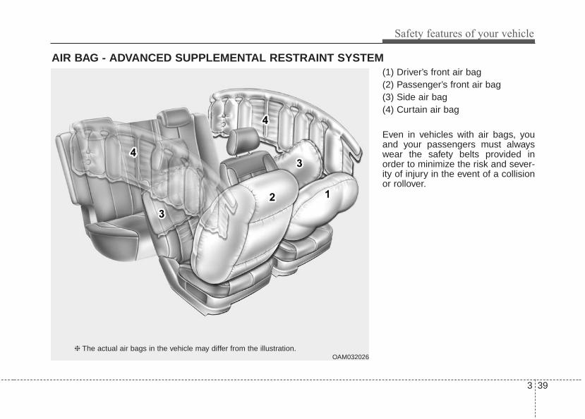
(1) Driver’s front air bag(2) Passenger’s front air bag(3) Side air bag(4) Curtain air bag
Even in vehicles with air bags, youand your passengers must alwayswear the safety belts provided inorder to minimize the risk and sever-ity of injury in the event of a collisionor rollover.
AIR BAG - ADVANCED SUPPLEMENTAL RESTRAINT SYSTEM
❈ The actual air bags in the vehicle may differ from the illustration.OAM032026

Safety features of your vehicle
403
How does the air bag systemoperate • Air bags are activated (able to
inflate if necessary) only when theignition switch is turned to the ONor START position.
• The appropriate air bags inflateinstantly in the event of a seriousfrontal collision or side collision inorder to help protect the occupantsfrom serious physical injury.
• There is no single speed at whichthe air bags will inflate.Generally, air bags are designed toinflate based upon the severity of acollision and its direction. Thesetwo factors determine whether thesensors produce an electronicdeployment/ inflation signal.
• Air bag deployment depends on anumber of factors including vehiclespeed, angles of impact and thedensity and stiffness of the vehi-cles or objects which your vehiclehits in the collision. The determin-ing factors are not limited to thosementioned above.
• The front air bags will completelyinflate and deflate in an instant.It is virtually impossible for you tosee the air bags inflate during anaccident.It is much more likely that you willsimply see the deflated air bagshanging out of their storage com-partments after the collision.
• In addition to inflating in seriousside collisions, side and/or curtainair bags will inflate if the sensingsystem detects a rollover.
• When a rollover is detected, cur-tain air bags will remain inflatedlonger to help provide protectionfrom ejection, especially whenused in conjunction with the seatbelts.
• In order to help provide protection,the air bags must inflate rapidly.The speed of the air bag inflation isa consequence of extremely shorttime in which to inflate the air bagbetween the occupant and thevehicle structures before the occu-pant impacts those structures. Thisspeed of inflation reduces the riskof serious or life-threateninginjuries and is thus a necessarypart of the air bag design.However, air bag inflation can alsocause injuries which can includefacial abrasions, bruises and bro-ken bones because the inflationspeed also causes the air bags toexpand with a great deal of force.
• There are even circumstancesunder which contact with thesteering wheel or passenger airbag can cause fatal injuries,especially if the occupant ispositioned excessively close tothe steering wheel or passengerair bag.

3 41
Safety features of your vehicle
Noise and smokeWhen inflated, the air bags make aloud noise and leave smoke andpowder in the air inside the vehicle.This is normal and is a result of theignition of the air bag inflator. Afterthe air bag inflates, you may feel sub-stantial discomfort in breathing dueto the contact of your chest with boththe seat belt and the air bag, as wellas from breathing the smoke andpowder. Open your doors and/orwindows as soon as possible afterimpact in order to reduce discom-fort and prevent prolonged expo-sure to the smoke and powder.Though smoke and powder are non-toxic, it may cause irritation to theskin (eyes, nose and throat, etc). Ifthis is the case, wash and rinse withcold water immediately and consult adoctor if the symptom persists.
WARNING- Hot components
Do not touch the air bag storagearea's internal componentsimmediately after airbag infla-tion. The air bag related parts inthe steering wheel, instrumentpanel and the roof rails abovethe front and rear doors arevery hot. Hot components canresult in burn injuries.
WARNING- Airbag inflation
Sit as far back as possible fromthe steering wheel while stillmaintaining comfortable con-trol of your vehicle. A distanceof at least 10" from your chestto the steering wheel is recom-mended. Failure to do so canresult in airbag inflation injuriesto the driver.

Safety features of your vehicle
423
Do not install a child restraint onthe front passenger’s seat.
Never place a rear-facing childrestraint in the front passenger’sseat. If the air bag deploys, it wouldimpact the rear-facing child restraint,causing serious or fatal injury.In addition, do not place front-facingchild restraints in the front passen-ger’s seat either. If the front passen-ger air bag inflates, it could causeserious or fatal injuries to the child.
Air bag warning light
The purpose of air bag warning lightin your instrument panel is to alertyou of a potential problem with yourair bag system, which could includeyour side and/or curtain air bagsused for rollover protection.
1JBH3051
W7-147
WARNING - Air bagdeployment
When children are seated in therear outboard seats of a vehicleequipped with side and/or cur-tain air bags, install the childrestraint system as far awayfrom the door side as possible.Inflation of the side and/or cur-tain air bags could impact thechild.

3 43
Safety features of your vehicle
When the ignition switch is turnedON, the warning light should illumi-nate for approximately 6 seconds,then go off. Have the systemchecked by an authorized Kia dealer-ship if:• The light does not turn on briefly
when you turn the ignition ON.• The light stays on after illuminating
for approximately 6 seconds.• The light comes on while the vehi-
cle is in motion.• The light blinks when the ignition
switch is in ON position.
SRS components and functions
The SRS consists of the followingcomponents:1. Driver's front air bag module2. Passenger's front air bag module3. Side air bag modules4. Curtain air bag modules5. Retractor pre-tensioner assemblies6. Air bag warning light7. SRS control module (SRSCM)/
Rollover sensor8. Front impact sensors9. Side impact sensors
10. PASSENGER “AIR BAG OFF”indicator (Front passenger’s seatonly)
11. Occupant detection system(Front passenger’s seat only)
12. Driver’s and front passenger’sseat belt buckle sensors
13. Emergency fastening device(EFD)
14. Side pressure impact sensor
The SRSCM continually monitors allSRS components while the ignitionswitch is ON to determine if a crashimpact is severe enough to requireair bag deployment or pre-tensionerseat belt deployment.
OPS034060N/Q
, ,
, ,

Safety features of your vehicle
443
If the air bag warning light illuminat-ed for more than, 6 seconds after theignition is turned on, or of it illumi-nates during vehicle operation, anSRS component may not be func-tioning properly and you should haveyour vehicle checked by an author-ized Kia dealer.
If any of the following conditionsoccurs, this indicates a malfunctionin the air bag system. Have anauthorized Kia dealer inspect the airbag system as soon as possible.• The light does not turn on briefly
when you turn the ignition ON.• The light stays on after illuminating
for approximately 6 seconds.• The light comes on while the vehi-
cle is in motion.• The light blinks when the ignition
switch is in ON position. The front air bag modules are locat-ed both in the center of the steeringwheel and in the front passenger'spanel above the glove box. When theSRSCM detects a sufficiently severeimpact to the front of the vehicle, itwill automatically deploy the front airbags.
B240B01L
Driver’s front air bag (1)
W7-147

3 45
Safety features of your vehicle
Upon deployment, tear seams mold-ed directly into the pad covers willseparate under pressure from theexpansion of the air bags. Furtheropening of the covers then allows fullinflation of the air bags.
A fully inflated air bag, in combina-tion with a properly worn seat belt,slows the driver's or the passenger'sforward motion, reducing the risk ofhead and chest injury.
After complete inflation, the air bagimmediately starts deflating, enablingthe driver to maintain forward visibilityand the ability to steer or operateother controls.
B240B02L
Driver’s front air bag (2)
B240B03L
Driver’s front air bag (3)
B240B05L
Passenger’s front air bag
WARNING- Air bag obstructions
Do not install or place anyaccessories on the steeringwheel, instrument panel, or onthe front passenger's panelabove the glove box in a vehi-cle. Such objects may becomedangerous projectiles if the airbag deploys.

Safety features of your vehicle
463
If an air bag deploys, there may be aloud noise followed by a fine dustreleased in the vehicle. These condi-tions are normal and are not haz-ardous - the air bags are packed inthis fine powder. The dust generatedduring air bag deployment maycause skin or eye irritation as well asaggravate asthma for some persons.Always wash all exposed skin areasthoroughly with lukewarm water anda mild soap after an accident inwhich the air bags were deployed.
The SRS can function only when theignition switch is in the ON position. Ifthe SRS air bag warning light doesnot illuminate, or continuouslyremains on after illuminating forabout 6 seconds when the ignitionswitch is turned to the ON position,or after the engine is started, comeson while driving, the SRS is notworking properly. If this occurs, haveyour vehicle immediately inspectedby an authorized Kia dealer.
✽✽ NOTICEBefore you replace a fuse or discon-nect a battery terminal, turn theignition switch to the LOCK posi-tion and remove the ignition switch.Never remove or replace the air bagrelated fuse(s) when the ignitionswitch is in the ON position. Failureto observe this warning will causethe SRS air bag warning light to illu-minate.
Occupant Detection System(ODS)
Your vehicle is equipped with anoccupant detection system in thefront passenger's seat.The occupant detection system isdesigned to detect the presence of aproperly-seated front passenger anddetermine if the passenger's front airbag should be enabled (may inflate)or not. Only the front passenger frontair bag is controlled by the OccupantDetection System.Do not put anything in front of thepassenger air bag indicator.
WARNING - Flyingobjects
Do not place any objects (anumbrella, bag, etc.) between thefront door and the front seat.Such objects may become dan-gerous projectiles if the sideairbag inflates.
OPS033020

3 47
Safety features of your vehicle
Main components of the occu-pant detection system• A detection device located within
the front passenger seat cushion.• An electronic system which deter-
mines whether the passenger airbag systems should be activatedor deactivated.
• A indicator light located on theinstrument panel which illuminatesthe words PASSENGER AIR BAG“OFF” indicating the front passen-ger air bag system is deactivated.
• The instrument panel air bag warn-ing light is interconnected with theoccupant detection system.
If the front passenger seat is occu-pied by a person that the systemdetermines to be of appropriate size,and he/she sits properly (sittingupright with the seatback in anupright position, centered on theseat cushion with their seat belt on,legs comfortably extended and theirfeet on the floor), the PASSENGERAIR BAG “OFF” indicator will turn offand the front passenger's air bag willbe able to inflate, if necessary, infrontal crashes.You will find the PASSENGER AIRBAG “OFF” indicator on the centerfacia panel. This system detects theconditions 1~4 in the following tableand activates or deactivates the frontpassenger air bag based on theseconditions.Always be sure that you and all vehi-cle occupants are seated andrestrained properly (sitting uprightwith the seat in an upright position,centered on the seat cushion, withthe person’s legs comfortably extend-ed, feet on the floor, and wearing thesafety belt properly) for the mosteffective protection by the air bag andthe safety belt.
• The ODS (Occupant DetectionSystem) may not function properly ifthe passenger takes actions whichcan defeat the detection system.These include:
(1) Failing to sit in an upright position.(2) Leaning against the door or cen-
ter console.(3) Sitting towards the sides or the
front of the seat.(4) Putting legs on the dashboard or
resting them on other locationswhich reduce the passengerweight on the front seat.
(5) Improperly wearing the safetybelt.
(6) Reclining the seat back.(7) Wearing a thick cloth like ski wear
or hip protection wear.(8) Put on the seat an additional thick
cushion.

Safety features of your vehicle
483
Condition and operation in the front passenger occupant detectionsystem
*1 : The ODS system uses a field to evaluate a person's size to determine whether theair bag should deploy. It is possible for a child to be detected and activate the ODS,thus allowing the air bag to deploy.To maximize safety, do not allow children to ridein the front passenger seat.
*2 : Never install a child restraint system on the front passenger seat.
✽✽ NOTICEDo not modify or replace the front passenger seat. Don't place anything on orattach anything such as a blanket, front seat cover or after market seat heaterto the front passenger seat. This can adversely affect the occupant detectionsystem.
Condition detected by theoccupant detection
system
1. Adult or child*1
2. Child restraint system*2
3. Unoccupied
4. There is a malfunction
in the system
Off
On
On
Off
Off
Off
Off
On
Activated
Deactivated
Deactivated
Activated
"PASSENGER AIRBAG OFF" indicator
lightSRS warning light
Front passenger air bag
Indicator/Warning light Devices
WARNING - ODS SystemRiding in an improper positionadversely affects the OccupantDetection System and mayresult in the deactivation of thefront passenger airbag. It isimportant for the driver toinstruct the passenger as to theproper seating instructions ascontained in this manual.
(Continued)

3 49
Safety features of your vehicle
1KMN3663
1KMN3664
1KMN3665
- Never sit with hips shiftedtowards the front of the seat.
- Never lean on the door or cen-ter console.
- Never sit on one side of thefront passenger seat.
- Never place feet on the dash-board.
OVQ036013N
1KMN3662
- Never put a heavy load or anactive electronic device onthe front passenger seat orseatback pocket.
- Never excessively recline thefront passenger seatback.
OVQ036014N
- Never place feet on the frontpassenger seatback.
(Continued)
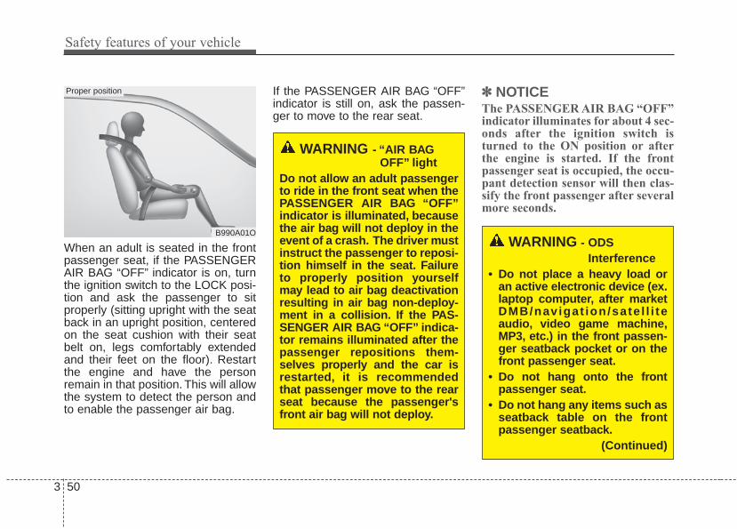
Safety features of your vehicle
503
When an adult is seated in the frontpassenger seat, if the PASSENGERAIR BAG “OFF” indicator is on, turnthe ignition switch to the LOCK posi-tion and ask the passenger to sitproperly (sitting upright with the seatback in an upright position, centeredon the seat cushion with their seatbelt on, legs comfortably extendedand their feet on the floor). Restartthe engine and have the personremain in that position. This will allowthe system to detect the person andto enable the passenger air bag.
If the PASSENGER AIR BAG “OFF”indicator is still on, ask the passen-ger to move to the rear seat.
✽✽ NOTICEThe PASSENGER AIR BAG “OFF”indicator illuminates for about 4 sec-onds after the ignition switch isturned to the ON position or afterthe engine is started. If the frontpassenger seat is occupied, the occu-pant detection sensor will then clas-sify the front passenger after severalmore seconds.
B990A01O
Proper position
WARNING - “AIR BAGOFF” light
Do not allow an adult passengerto ride in the front seat when thePASSENGER AIR BAG “OFF”indicator is illuminated, becausethe air bag will not deploy in theevent of a crash. The driver mustinstruct the passenger to reposi-tion himself in the seat. Failureto properly position yourselfmay lead to air bag deactivationresulting in air bag non-deploy-ment in a collision. If the PAS-SENGER AIR BAG “OFF” indica-tor remains illuminated after thepassenger repositions them-selves properly and the car isrestarted, it is recommendedthat passenger move to the rearseat because the passenger'sfront air bag will not deploy.
WARNING - ODSInterference
• Do not place a heavy load oran active electronic device (ex.laptop computer, after marketDMB/navigat ion/sate l l i teaudio, video game machine,MP3, etc.) in the front passen-ger seatback pocket or on thefront passenger seat.
• Do not hang onto the frontpassenger seat.
• Do not hang any items such asseatback table on the frontpassenger seatback.
(Continued)

3 51
Safety features of your vehicle
✽✽ NOTICEAir bags can only be used once -have an authorized Kia dealerreplace the air bag immediatelyafter deployment.
Any child age 12 and under should ridein the rear seat. Children too large forchild restraints should use the avail-able lap/shoulder belts. No matter whattype of crash, children of all ages aresafer when restrained in the rear seat.
✽✽ NOTICEDo not modify or replace the frontpassenger seat. Don't place anythingon or attach anything such as a blan-ket, front seat covers or after marketseat heater to the front passengerseat. This can adversely affect theoccupant detection system.
If the occupant detection system isnot working properly, the SRS air bagwarning light on the instrument panelwill illuminate because the passen-ger's front air bag is connected withthe occupant detection system. Ifthere is a malfunction of the occupantdetection system, the PASSENGERAIR BAG “OFF” indicator will not illu-minate and the passenger's front airbag will inflate in frontal impact crash-es even if there is no occupant in thefront passenger's seat.
Driver's and passenger's frontair bag
Your vehicle is equipped with anAdvanced Supplemental Restraint(Air Bag) System and lap/shoulderbelts at both the driver and passen-ger seating position.
OPS033021
OPS033022
Driver’s front air bag
Passenger’s front air bag
(Continued)• Do not place feet on the front
passenger seatback.• Do not place any items under
the front passenger seat.• Do not place sharp objects on
the front passenger seat.These may damage the occu-pant detection system, if theypuncture the seat cushion.
• Do not spill any liquids on theseat.
Any of the above could interferewith the proper operation of theODS sensor thereby increasingthe risk of an injury in an acci-dent.

Safety features of your vehicle
523
The indication of the system's pres-ence are the letters "AIR BAG"embossed on the air bag pad coveron the steering wheel and the pas-senger's side front panel pad abovethe glove box.
The SRS consists of air bagsinstalled under the pad covers in thecenter of the steering wheel and thepassenger's side front panel abovethe glove box.The purpose of the SRS is to providethe vehicle's driver and/or the frontpassenger with additional protectionthan that offered by the seat belt sys-tem alone in case of a frontal impactof sufficient severity. The SRS usessensors to gather information aboutthe driver's and front passenger'sseat belt usage and impact severity.
The seat belt buckle sensors deter-mine if the driver and front passen-ger's seat belts are fastened.
These sensors provide the ability tocontrol the SRS deployment based onwhether or not the seat belts are fas-tened, and how severe the impact is.
The advanced SRS offers the abilityto control the air bag inflation withtwo levels. A first stage level is pro-vided for moderate-severity impacts.A second stage level is provided formore severe impacts.
The passenger’s front air bag isdesigned to help reduce the injury ofchildren sitting close to the instru-ment panel in low speed collisions.However, children are safer if theyare restrained in the rear seat.
According to the impact severity andseat belt usage, the SRSCM (SRSControl Module) controls the air baginflation. Failure to properly wearseat belts can increase the risk orseverity of injury in an accident.
CAUTION - Seat TrackSensor
Do not place any objects under-neath the front seats as theycould damage the seat trackposition sensor or interfere withthe occupant detection system.

3 53
Safety features of your vehicle
Additionally, your vehicle is equippedwith an occupant detection system inthe front passenger's seat. The occu-pant detection system detects thepresence of a passenger in the frontpassenger's seat and will turn off thefront passenger's air bag under cer-tain conditions. For more detail, see"Occupant detection system" in thissection.
Manufacturers are required by gov-ernment regulations to provide acontact point concerning modifica-tions to the vehicle for persons withdisabilities, which modifications mayaffect the vehicle’s advanced air bagsystem. However, Kia does notendorse nor will it support anychanges to any part or structure ofthe vehicle that could affect theadvanced air bag system, includingthe occupant detection system.
Advanced air bags are combinedwith pre-tensioner seat belts to helpprovide enhanced occupant protec-tion in frontal crashes. Front air bagsare not intended to deploy in colli-sions in which sufficient protectioncan be provided by the pre-tensionerseat belt.
WARNING - ModificationModification to the seat struc-ture can cause the air bag todeploy at a different level thanshould be provided.
WARNING - Replacement /Modifications
The front passenger seat, dash-board or door should not bereplaced except by an author-ized Kia Premium dealer usingoriginal Kia parts designed forthis vehicle and model. Anyother such replacement or mod-ification could adversely affectthe operation of the occupantdetection system and youradvanced air bags.

Safety features of your vehicle
543
Front air bags are not intended todeploy in side-impact, rear-impact orrollover crashes. In addition, front airbags will not deploy in frontal crash-es below the deployment threshold.
Side air bag
Your vehicle is equipped with a sideair bag in each front seat. The pur-pose of the air bag is to provide thevehicle's driver and/or the front pas-senger with additional protection thanthat offered by the seat belt alone.
WARNING - SRS WiringDo not tamper with or discon-nect SRS wiring or other com-ponents of the SRS system.Doing so could result in injury,due to accidental deployment ofthe air bags or by rendering theSRS inoperative. OEP036096N
OVQ036018N
1VQA2091
Rear impact
Side impact
Rollover
OPS033037
OPS033023
❈ The actual air bags in the vehicle may dif-fer from the illustration.

3 55
Safety features of your vehicle
• The side air bags are designed todeploy during certain side-impactcollisions, depending on the crashseverity, angle, speed and point ofimpact.
• The side and/or curtain air bags donot only deploy on the side of theimpact but also on the oppositeside.
• The side and/or curtain air bags onboth sides of the vehicle will deployif a rollover or possible rollover isdetected.
• The side air bags are not designedto deploy in all side impact orrollover situations.
• The side air bag is supplemental tothe driver's and the passenger'sseat belt systems and is not a sub-stitute for them. Therefore yourseat belts must be worn at all timeswhile the vehicle is in mention.
• For best protection from the sideair bag system and to avoid beinginjured by the deploying side airbag, both front seat occupantsshould sit in an upright positionwith the seat belt properly fas-tened. The driver's hands shouldbe placed on the steering wheel atthe 9:00 and 3:00 positions. Thepassenger's arms and handsshould be placed on their laps.
• If seat or seat cover is damaged,have the vehicle checked andrepaired by an authorized Kia deal-er. Inform the dealer that your vehi-cle is equipped with side air bagsand an occupant detection system.
WARNING - Unexpecteddeployment
Avoid impact to the side impactairbag sensor when the ignitionswitch is ON to prevent unex-pected deployment of the sideimpact air bag.
WARNING - DeploymentDo not install any accessoriesincluding seat covers, on theside or near the side impact airbag as this may affect thedeployment of the side air bags.
WARNING - Flyingobjects
Do not place any objects (anumbrella, bag, etc.) between thefront door and the front seat.Such objects may become dan-gerous projectiles if the sideairbag inflates.

Safety features of your vehicle
563
Curtain air bag
Curtain air bags are located alongboth sides of the roof rails above thefront and rear doors.
They are designed to help protectoccupants in certain side impactsand to help prevent them from eject-ing out of the vehicle as a result of arollover, especially when the seat-belts are also in use.The curtain air bags are designed todeploy during certain side impact col-lisions, depending on the crash sever-ity, angle, speed and point of impact.The side and/or curtain air bags donot only deploy on the side of theimpact but also on the opposite side.Also, the curtain air bags on bothsides of the vehicle will deploy in cer-tain rollover situations.The curtain air bags are notdesigned to deploy in all side impactor rollover situations.Do not allow the passengers to leantheir heads or bodies against thedoors, put their arms on the doors,stretch their arms out of the windowor place objects between the doorsand passengers when they are seat-ed on seats equipped with sideimpact and/or curtain air bags.
✽✽ NOTICENever try to open or repair any com-ponents of the side and curtain airbag system. This should only bedone by an authorized Kia dealer.
❈ The actual air bags in the vehicle may dif-fer from the illustration.
OPS033024
OPS033038

3 57
Safety features of your vehicle
Why didn’t my air bag go off in acollision? (Inflation and non-infla-tion conditions of the air bag)There are many types of accidentsin which the air bag would not beexpected to provide additionalprotection.These include rear impacts, sec-ond or third collisions in multipleimpact accidents, as well as lowspeed impacts.
Air bag collision sensors
(1) SRS control module/Rollover sensor(2) Front impact sensor
(3) Side impact sensor(4) Side pressure sensor
OPS033025N/OPS033026/OPS033027/OPS033028/OPS033029
1 2 3 4

Safety features of your vehicle
583
• Problems may arise if the sensorinstallation angles are changeddue to the deformation of the frontbumper, front end module, body orfront doors and/or B pillar whereside collision sensors are installed.Have the vehicle checked andrepaired by an authorized Kia deal-er.
• Installing bumper guards (or sidestep or running board) or replacinga bumper (or front door module)with non-genuine parts mayadversely affect your vehicle’s col-lision and air bag deployment per-formance.
Air bag inflation conditions
Front air bags
Front air bags are designed to inflatein a frontal collision depending onthe intensity, speed or angles ofimpact of the front collision.
1VQA2084
WARNING- Air bag sensors
• Do not hit or allow any objectsto impact the locations whereair bags or sensors areinstalled.This may cause unexpectedair bag deployment, whichcould result in serious per-sonal injury or death.
• If the installation location orangle of the sensors is alteredin any way, the air bags maydeploy when they should notor they may not deploy whenthey should.Therefore, do not try to per-form maintenance on oraround the air bag sensors.Have the vehicle checked andrepaired by an authorized Kiadealer.

3 59
Safety features of your vehicle
Side air/or curtain air bags
Side air bags (side and/or curtain airbags) are designed to inflate when animpact is detected by side collisionsensors depending on the strength,speed or angles of impact resultingfrom a side impact collision.
Also, the side and curtain air bags aredesigned to inflate when a rollover isdetected by a rollover sensor.Although the front air bags (driver’sand front passenger’s air bags) aredesigned to inflate in frontal colli-sions, they also may inflate in othertypes of collisions if the front impactsensors detect a sufficient frontalforce in another type of impact. Sideand curtain air bags are designed toinflate in certain side impact colli-sions. They may inflate in other typeof collisions where a side force isdetected by the sensors. Side air bagand/or curtain air bags may alsoinflate where rollover sensors indi-cate the possibility of a rolloveroccurring (even if none actuallyoccurs) or in other situations, incluid-ing when the vehicle is tilted whilebeing towed. Even where side and/orcurtain air bags would not provideimpact protection in a rollover, how-ever, they will deploy to prevent ejec-tion of occupants, especially thosewho are restrained with seat belts.
If the vehicle chassis is impacted bybumps or objects on unimprovedroads, the air bags may deploy. Drivecarefully on unimproved roads or onsurfaces not designed for vehicletraffic to prevent unintended air bagdeployment.
OVQ036018N
OPS033039
❈ The actual air bags in the vehicle may dif-fer from the illustration.

Safety features of your vehicle
603
Air bag non-inflation conditions
• In certain low-speed collisions theair bags may not deploy. The airbags are designed not to deploy insuch cases because they may notprovide benefits beyond the pro-tection of the seat belts in such col-lisions.
• Air bags are not designed to inflatein rear collisions, because occu-pants are moved backward by theforce of the impact. In this case,inflated air bags would not be ableto provide any additional benefit.
• Front air bags may not inflate inside impact collisions, becauseoccupants move to the direction ofthe collision, and thus in sideimpacts, frontal air bag deploymentwould not provide additional occu-pant protection.
OUN036087 OVQ036018N
1VQA2086

3 61
Safety features of your vehicle
• In an angled collision, the force ofimpact may direct the occupants ina direction where the air bagswould not be able to provide anyadditional benefit, and thus thesensors may not deploy any airbags.
• Just before impact, drivers oftenbrake heavily. Such heavy brakinglowers the front portion of the vehi-cle causing it to “ride” under a vehi-cle with a higher ground clearance.Air bags may not inflate in this"under-ride" situation becausedeceleration forces that are detect-ed by sensors may be significantlyreduced by such “under-ride” colli-sions.
• Front air bags may not inflate inrollover accidents because frontairbag deployment would not pro-vide additional occupant protection.
1VQA2090 1VQA20911VQA2089

Safety features of your vehicle
623
• Air bags may not inflate if the vehi-cle collides with objects such asutility poles or trees, where thepoint of impact is concentrated toone area and the full force of theimpact is not delivered to the sen-sors.
SRS CareThe SRS is virtually maintenance-free and so there are no parts you cansafely service by yourself. If the SRSair bag warning light does not illumi-nate, or continuously remains on,have your vehicle immediatelyinspected by an authorized Kia dealer.
Any work on the SRS system, suchas removing, installing, repairing, orany work on the steering wheel, thefront passenger’s panel, front seatsand roof rails must be performed byan authorized Kia dealer. Improperhandling of the SRS system mayresult in serious personal injury.
For cleaning the air bag pad covers,use only a soft, dry cloth or onewhich has been moistened with plainwater. Solvents or cleaners couldadversely affect the air bag coversand proper deployment of the sys-tem.If components of the air bag systemmust be discarded, or if the vehiclemust be scrapped, certain safetyprecautions must be observed. Anauthorized Kia dealer knows theseprecautions and can give you thenecessary information. Failure to fol-low these precautions and proce-dures could increase the risk of per-sonal injury.
1VQA2092

3 63
Safety features of your vehicle
Adding equipment to or modi-fying your air bag-equippedvehicleIf you modify your vehicle by changingyour vehicle's frame, bumper system,front end or side sheet metal or rideheight, this may affect the operation ofyour vehicle's air bag system.
Air bag warning label
Air bag warning labels, somerequired by the Canada MotorVehicle Safety Standards (CMVSS),are attached to the sunvisor to alertthe driver and passengers of poten-tial risks of the air bag system.
WARNING - Tamperingwith SRS
Do not tamper with or discon-nect SRS wiring, or other com-ponents of the SRS system.Doing so could result in theaccidental inflation of the airbags or by rendering the SRSinoperative.
WARNING - TowingVehicle
Always have the ignition offwhen your vehicle is beingtowed. The side air bags mayinflate if the vehicle is tiltedsuch as when being towedbecause of the rollover sensorsin the vehicle.
OPS033030
OAM039041

Features of your vehicle
Key . . . . . . . . . . . . . . . . . . . . . . . . . . . . . . . . . . . . . . . 4-4• Record your key number . . . . . . . . . . . . . . . . . . . . . . . 4-4• Key operations . . . . . . . . . . . . . . . . . . . . . . . . . . . . . . . . 4-4• Transmitter precautions . . . . . . . . . . . . . . . . . . . . . . . . 4-6• Battery replacement . . . . . . . . . . . . . . . . . . . . . . . . . . . 4-7• Immobilizer system . . . . . . . . . . . . . . . . . . . . . . . . . . . . 4-8
Smart key . . . . . . . . . . . . . . . . . . . . . . . . . . . . . . . . 4-11• Record your key number . . . . . . . . . . . . . . . . . . . . . . 4-11• Smart key function . . . . . . . . . . . . . . . . . . . . . . . . . . . 4-11• Loss of the smart key . . . . . . . . . . . . . . . . . . . . . . . . . 4-14• Smart key precautions . . . . . . . . . . . . . . . . . . . . . . . . 4-15• Smart key immobilizer system. . . . . . . . . . . . . . . . . . 4-15• Battery replacement . . . . . . . . . . . . . . . . . . . . . . . . . . 4-17
Door locks . . . . . . . . . . . . . . . . . . . . . . . . . . . . . . . . 4-19• Operating door locks from outside the vehicle . . . . 4-19• Operating door locks from inside the vehicle. . . . . . 4-20• Impact sensing door unlock system. . . . . . . . . . . . . . 4-22• Auto door lock/unlock feature . . . . . . . . . . . . . . . . . . 4-22• Speed sensing door lock system . . . . . . . . . . . . . . . . . 4-22• Child-protector rear door lock . . . . . . . . . . . . . . . . . 4-23
Tailgate . . . . . . . . . . . . . . . . . . . . . . . . . . . . . . . . . . 4-24• Opening the tailgate . . . . . . . . . . . . . . . . . . . . . . . . . . 4-24• Closing the tailgate . . . . . . . . . . . . . . . . . . . . . . . . . . . 4-24• Emergency tailgate safety release . . . . . . . . . . . . . . . 4-25
Windows . . . . . . . . . . . . . . . . . . . . . . . . . . . . . . . . . 4-26• Power windows . . . . . . . . . . . . . . . . . . . . . . . . . . . . . . 4-27
Hood. . . . . . . . . . . . . . . . . . . . . . . . . . . . . . . . . . . . . 4-32• Opening the hood . . . . . . . . . . . . . . . . . . . . . . . . . . . . 4-32• Closing the hood . . . . . . . . . . . . . . . . . . . . . . . . . . . . . 4-32
Fuel filler lid . . . . . . . . . . . . . . . . . . . . . . . . . . . . . . 4-34• Opening the fuel filler lid . . . . . . . . . . . . . . . . . . . . . . 4-34• Closing the fuel filler lid . . . . . . . . . . . . . . . . . . . . . . . 4-34
Panoramic sunroof . . . . . . . . . . . . . . . . . . . . . . . . . 4-37• Sunroof open warning. . . . . . . . . . . . . . . . . . . . . . . . . 4-38• Sliding the sunroof . . . . . . . . . . . . . . . . . . . . . . . . . . . 4-38• Tilting the sunroof. . . . . . . . . . . . . . . . . . . . . . . . . . . . 4-39• Sunshade . . . . . . . . . . . . . . . . . . . . . . . . . . . . . . . . . . . 4-40• Resetting the sunroof . . . . . . . . . . . . . . . . . . . . . . . . . 4-41
Steering wheel. . . . . . . . . . . . . . . . . . . . . . . . . . . . . 4-43• Electric power steering (EPS) . . . . . . . . . . . . . . . . . . 4-43• Tilt and telescopic steering . . . . . . . . . . . . . . . . . . . . 4-44• Heated steering wheel . . . . . . . . . . . . . . . . . . . . . . . . . 4-45• Horn . . . . . . . . . . . . . . . . . . . . . . . . . . . . . . . . . . . . . . . 4-46• FLEX steer . . . . . . . . . . . . . . . . . . . . . . . . . . . . . . . . . . 4-46
Mirrors . . . . . . . . . . . . . . . . . . . . . . . . . . . . . . . . . . 4-49• Inside rearview mirror . . . . . . . . . . . . . . . . . . . . . . . . 4-49• Outside rearview mirror . . . . . . . . . . . . . . . . . . . . . . 4-51
4

Instrument cluster . . . . . . . . . . . . . . . . . . . . . . . . . 4-54• Instrument Cluster Control . . . . . . . . . . . . . . . . . . . . 4-55• LCD Display Control . . . . . . . . . . . . . . . . . . . . . . . . . 4-55• Gauges . . . . . . . . . . . . . . . . . . . . . . . . . . . . . . . . . . . . . 4-56• Transaxle Shift Indicator . . . . . . . . . . . . . . . . . . . . . . 4-60
LCD Display . . . . . . . . . . . . . . . . . . . . . . . . . . . . . . 4-62• LCD Modes . . . . . . . . . . . . . . . . . . . . . . . . . . . . . . . . . 4-62• Service Mode . . . . . . . . . . . . . . . . . . . . . . . . . . . . . . . . 4-63• User Settings Mode . . . . . . . . . . . . . . . . . . . . . . . . . . . 4-64• A/V Mode . . . . . . . . . . . . . . . . . . . . . . . . . . . . . . . . . . . 4-66• Turn By Turn Mode . . . . . . . . . . . . . . . . . . . . . . . . . . 4-66• Warning Messages. . . . . . . . . . . . . . . . . . . . . . . . . . . . 4-67
Trip computer. . . . . . . . . . . . . . . . . . . . . . . . . . . . . 4-72• Overview. . . . . . . . . . . . . . . . . . . . . . . . . . . . . . . . . . . . 4-72• Trip A/B . . . . . . . . . . . . . . . . . . . . . . . . . . . . . . . . . . . . 4-73• Fuel Economy . . . . . . . . . . . . . . . . . . . . . . . . . . . . . . . 4-74
Warning and indicator lights . . . . . . . . . . . . . . . . 4-76• Warning lights . . . . . . . . . . . . . . . . . . . . . . . . . . . . . . . 4-76• Indicator Lights . . . . . . . . . . . . . . . . . . . . . . . . . . . . . . 4-83
Rear camera display . . . . . . . . . . . . . . . . . . . . . . . 4-88Lighting . . . . . . . . . . . . . . . . . . . . . . . . . . . . . . . . . . 4-89
• Headlamp escort . . . . . . . . . . . . . . . . . . . . . . . . . . . . . 4-89• Battery saver function. . . . . . . . . . . . . . . . . . . . . . . . . 4-89• Daytime running light. . . . . . . . . . . . . . . . . . . . . . . . . 4-89
• Lighting control . . . . . . . . . . . . . . . . . . . . . . . . . . . . . . 4-90• High beam operation . . . . . . . . . . . . . . . . . . . . . . . . . 4-91• Turn signals and lane change signals . . . . . . . . . . . . 4-92• Front fog light . . . . . . . . . . . . . . . . . . . . . . . . . . . . . . . 4-93
Wipers and Washers . . . . . . . . . . . . . . . . . . . . . . . 4-94• Windshield wiper/washer . . . . . . . . . . . . . . . . . . . . . . 4-94• Rear window wiper/washer . . . . . . . . . . . . . . . . . . . . 4-94• Windshield wipers . . . . . . . . . . . . . . . . . . . . . . . . . . . 4-94• Windshield washers. . . . . . . . . . . . . . . . . . . . . . . . . . . 4-95• Rear window wiper and washer switch . . . . . . . . . . 4-96
Interior light . . . . . . . . . . . . . . . . . . . . . . . . . . . . . . 4-97• Interior lamp AUTO cut . . . . . . . . . . . . . . . . . . . . . . . 4-97• Map lamp . . . . . . . . . . . . . . . . . . . . . . . . . . . . . . . . . . 4-97• Room lamp. . . . . . . . . . . . . . . . . . . . . . . . . . . . . . . . . . 4-98• Luggage room lamp . . . . . . . . . . . . . . . . . . . . . . . . . . 4-99• Portable lamp usage . . . . . . . . . . . . . . . . . . . . . . . . . . 4-99• Glove box lamp . . . . . . . . . . . . . . . . . . . . . . . . . . . . . 4-101• Vanity mirror lamp . . . . . . . . . . . . . . . . . . . . . . . . . . 4-101
Defroster . . . . . . . . . . . . . . . . . . . . . . . . . . . . . . . . 4-102• Rear window defroster . . . . . . . . . . . . . . . . . . . . . . . 4-102
Manual climate control system . . . . . . . . . . . . . 4-104• Heating and air conditioning . . . . . . . . . . . . . . . . . . 4-105• System operation . . . . . . . . . . . . . . . . . . . . . . . . . . . . 4-110• Climate control air filter. . . . . . . . . . . . . . . . . . . . . . 4-112
4

• Checking the amount of air conditioner refrigerant and compressor lubricant. . . . . . . . . . 4-113
Automatic climate control system. . . . . . . . . . . . 4-114• Automatic heating and air conditioning . . . . . . . . . 4-115• Manual heating and air conditioning . . . . . . . . . . . 4-116• System operation . . . . . . . . . . . . . . . . . . . . . . . . . . . . 4-123• Climate control air filter. . . . . . . . . . . . . . . . . . . . . . 4-125• Checking the amount of air conditioner
refrigerant and compressor lubricant. . . . . . . . . . 4-125Windshield defrosting and defogging. . . . . . . . . 4-127
• Manual climate control system . . . . . . . . . . . . . . . . 4-127• Automatic climate control system . . . . . . . . . . . . . . 4-128• Defogging logic. . . . . . . . . . . . . . . . . . . . . . . . . . . . . . 4-129
Clean air . . . . . . . . . . . . . . . . . . . . . . . . . . . . . . . . 4-131Storage compartment. . . . . . . . . . . . . . . . . . . . . . 4-132
• Center console storage . . . . . . . . . . . . . . . . . . . . . . . 4-132• Glove box . . . . . . . . . . . . . . . . . . . . . . . . . . . . . . . . . . 4-132• Cool box . . . . . . . . . . . . . . . . . . . . . . . . . . . . . . . . . . . 4-133• Sunglass holder . . . . . . . . . . . . . . . . . . . . . . . . . . . . . 4-133• Luggage box . . . . . . . . . . . . . . . . . . . . . . . . . . . . . . . . 4-134
Interior features . . . . . . . . . . . . . . . . . . . . . . . . . . 4-135• Cup holder . . . . . . . . . . . . . . . . . . . . . . . . . . . . . . . . . 4-135• Sunvisor . . . . . . . . . . . . . . . . . . . . . . . . . . . . . . . . . . . 4-136• Seat warmer . . . . . . . . . . . . . . . . . . . . . . . . . . . . . . . . 4-136• Seat air ventilation . . . . . . . . . . . . . . . . . . . . . . . . . . 4-138
• Rear seat warmer . . . . . . . . . . . . . . . . . . . . . . . . . . . 4-138• Power outlet . . . . . . . . . . . . . . . . . . . . . . . . . . . . . . . . 4-138• Clothes hanger . . . . . . . . . . . . . . . . . . . . . . . . . . . . . . 4-140• Floor mat anchor(s). . . . . . . . . . . . . . . . . . . . . . . . . . 4-141• Luggage net holder . . . . . . . . . . . . . . . . . . . . . . . . . . 4-142• Cargo area cover . . . . . . . . . . . . . . . . . . . . . . . . . . . . 4-142
Exterior features. . . . . . . . . . . . . . . . . . . . . . . . . . 4-145• Mounting bracket for roof carrier. . . . . . . . . . . . . . 4-145
Audio system. . . . . . . . . . . . . . . . . . . . . . . . . . . . . 4-147• Antenna . . . . . . . . . . . . . . . . . . . . . . . . . . . . . . . . . . . 4-147• Audio remote control. . . . . . . . . . . . . . . . . . . . . . . . . 4-148• Aux and USB port . . . . . . . . . . . . . . . . . . . . . . . . . . . 4-149• Speaker lights. . . . . . . . . . . . . . . . . . . . . . . . . . . . . . . 4-150
4

Features of your vehicle
44
Record your key numberThe key code num-ber is stamped onthe key code tagattached to the keyset. Should you
lose your keys, this number willenable an authorized Kia dealer toduplicate the keys easily. Removethe key code tag and store it in a safeplace. Also, record the key codenumber and keep it in a safe andhandy place, but not in the vehicle.
Key operations
• Used to start the engine.• Used to lock and unlock the doors.
• To unfold the key, press the releasebutton (1) then the key will unfoldautomatically. To fold the key, foldthe key manually while pressingthe release button (1).
KEY
CAUTIONDo not fold the key withoutpressing the release button.This may damage the key.
WARNING - Aftermarketkey
Use only Kia original parts forthe ignition key in your vehicle.If an aftermarket key is used,the ignition switch may notreturn to ON after START. If thishappens, the starter will contin-ue to operate causing damageto the starter motor and possi-ble fire due to excessive currentin the wiring.
OED036001A
OXMA043331
■ Type A
■ Type B

4 5
Features of your vehicle
Door Lock (1)
1. Close all doors, engine hood andtailgate.
2. Press the lock button(1).3. All doors and tailgate will lock. The
hazard warning lights will blinkonce.
4. If the lock button is pressed oncemore within 4 seconds, the hazardwarning lights will blink and thehorn will sound once.
5. Make sure that doors are locked bychecking the door lock button insideor pulling the outside door handle.
Door Unlock (2) 1. Press the unlock button(2).2. The driver's door will unlock. The
hazard warning lights will blink twotimes.
3. Press the unlock button(2) twicewithin 4 seconds and all doors andtailgate will unlock. The hazardwarning lights will blink two times.
✽✽ NOTICEYou can activate or deactivate theTwo Turn Unlock function. Refer to"User settings" in this chapter.
OXMA043317
WARNING - Ignition keyNever leave the keys in yourvehicle with unsupervised chil-dren. Leaving children unattend-ed in a vehicle with a manualignition key or a smart key isdangerous. Children copy adultsand they could place the key inthe ignition switch or press thestart button. The key wouldenable children to operate powerwindows or other controls, oreven make the vehicle move,which could result in seriousbodily injury or death. result inserious bodily injury or death.

Features of your vehicle
64
Tailgate unlock (3)The tailgate is unlocked if the buttonis pressed for more than 1 second.Also, once the tailgate is opened andthen closed, the tailgate will belocked automatically.
Panic (4)The horn sounds and hazard warn-ing lights flash for about 30 secondsif this button is pressed for more than1 second.To stop the horn and lights,press any button except the trunkbutton on the transmitter.
Transmitter precautions✽✽ NOTICE• The transmitter will not work if any
of following occur:- The ignition key is in the ignition
switch.- You exceed the operating dis-
tance limit (about 10 m [30 feet]).- The battery in the transmitter is
weak.- Other vehicles or objects may be
blocking the signal.- The weather is extremely cold.- The transmitter is close to a radio
transmitter such as a radio sub-station or an airport which caninterfere with normal operation ofthe transmitter.
(Continued)
(Continued)• When the transmitter does not work
correctly, open and close the doorwith the ignition key. If you have aproblem with the transmitter, con-tact an authorized Kia dealer.
• If the transmitter is in close proxim-ity to your mobile phone, the signalcould be blocked by your mobilephones normal operational signals.This is especially important whenthe phone is active such as makingand receiving calls, text messag-ing, and/or sending/receivingemails. Avoid placing the transmit-ter and your mobile phone in thesame pants or jacket pocket andalways try to maintain an adequatedistance between the two devices.

4 7
Features of your vehicle
✽✽ NOTICEIf the keyless entry system is inoper-ative due to exposure to water or liq-uids, it will not be covered by yourmanufacturer’s vehicle warranty.
Battery replacement
The transmitter uses a 3 volt lithiumbattery which will normally last forseveral years. When replacement isnecessary, use the following proce-dure.1. Insert a slim tool into the slot and
gently pry open the transmittercenter cover.
2. Replace the battery with a newbattery (CR2032). When replacingthe battery, make sure the batteryis positioned battery.
3. Install the battery in the reverseorder of removal.
For replacement transmitters, see anauthorized Kia dealer for transmitterreprogramming.• The transmitter is designed to give
you years of trouble-free use, how-ever it can malfunction if exposed tomoisture or static electricity. If youare unsure how to use your trans-mitter or replace the battery, contactan authorized Kia dealer.
• Using the wrong battery can causethe transmitter to malfunction. Besure to use the correct battery.
• To avoid damaging the transmitter,don't drop it, get it wet, or expose itto heat or sunlight.
• An inappropriately disposedbattery can be harmful to theenvironment and may causehuman health. Dispose thebattery according to yourlocal law(s) or regulation.
OYDDCO2005
CAUTION Keep the transmitter away fromwater or any liquid as it canbecome damaged and not func-tion properly.

Features of your vehicle
84
Immobilizer systemYour vehicle is equipped with anelectronic engine immobilizer systemto reduce the risk of unauthorizedvehicle use.Your immobilizer system is com-prised of a small transponder in theignition key and electronic devicesinside the vehicle.With the immobilizer system, when-ever you insert your ignition key intothe ignition switch and turn it to ON,it checks and determines and verifiesif the ignition key is valid.If the key is determined to be valid,the engine will start.If the key is determined to be invalid,the engine will not start.
To activate the immobilizer sys-tem:Turn the ignition key to the OFF posi-tion. The immobilizer system acti-vates automatically. Without a validignition key for your vehicle, theengine will not start.
To deactivate the immobilizersystem:Insert the ignition key into the keycylinder and turn it to the ON position.In order to prevent theft of your vehi-cle, do not leave spare keys any-where in your vehicle. YourImmobilizer password is a customerunique password and should be keptconfidential. Do not leave this num-ber anywhere in your vehicle.
CAUTION - Transmitterdamage
Do not drop, wet or expose thekeyless entry system transmit-ter to heat or sunlight or it willbe damaged.
IC WARNINGThis device complies withIndustry Canada licence-exemptRSS standard(s).Operation is subject to the fol-lowing two conditions: (1) thisdevice may not cause interfer-ence, and (2) this device mustaccept any interference, includ-ing interference that may causeundesired operation of thedevice.

4 9
Features of your vehicle
✽✽ NOTICEWhen starting the engine, do not usethe key with other immobilizer keysaround. Otherwise the engine maynot start or may stop soon after itstarts. Keep each key separate inorder to avoid a starting malfunc-tion.
Do not put metal accessories nearthe ignition switch.Metal accessories may interrupt thetransponder signal and may preventthe engine from being started.
✽✽ NOTICEIf you need additional keys or loseyour keys, contact an authorizedKia dealer.
This device complies with IndustryCanada Standard RSS-210.Operation is subject to the followingtwo conditions:1. This device may not cause harm-
ful interference, and 2. This device must accept any inter-
ference received, including inter-ference that may cause undesiredoperation.
✽✽ NOTICEChanges or modifications notexpressly approved by the partyresponsible for compliance couldvoid the user’s authority to operatethe equipment. If the keyless entrysystem is inoperative due to changesor modifications not approved bythe party responsible for compli-ance, it will not be covered by yourmanufacturer’s vehicle warranty.
CAUTION - Immobilizerdamage
Do not expose your immobilizersystem to moisture, static elec-tricity and rough handling. Thismay damage your immobilizer.
CAUTION - Immobilizeralterations
Do not change, alter or adjustthe immobilizer system becauseit could cause the immobilizersystem to malfunction.

Features of your vehicle
104
Limp home (override) proce-dureWhen you turn the ignition switch tothe ON position, if the immobilizerindicator ( ) goes off after blink-ing 5 times, your transponderequipped in the ignition key is out oforder. You cannot start the enginewithout the limp home procedure. Tostart the engine, you have to inputyour password by using the ignitionswitch. Your password is only avail-able from an authorized Kia dealer-ship. Contact an authorized dealerfor more information.The following procedure is how toinput your password of “2345” as anexample.1. Turn the ignition switch to the ON
position. The immobilizer indicator( ) will blink 5 times and go offindicating the beginning of the limphome procedure.
2. Turn the ignition switch to the ACCposition.
3. To enter the first digit (in thisexample “2”), turn the ignitionswitch to the ON and ACC positiontwice. Perform the same proce-dure for the next digits between 3seconds and 10 seconds (forexample, for “3”, turn the ignitionON and ACC 3 times).
4. If all of the digits have been inputsuccessfully, you have to start theengine within 30 seconds. If youattempt to start the engine after 30seconds, the engine will not startand you will have to input yourpassword again.
After performing the limp home pro-cedure, you have to see an author-ized Kia dealer immediately toinspect and repair your ignition keyor immobilizer system.

4 11
Features of your vehicle
Record your key numberThe key code num-ber is stamped onthe key code tagattached to the keyset. Should you
lose your keys, this number willenable an authorized Kia dealer toduplicate the keys easily. Removethe key code tag and store it in a safeplace. Also, record the key codenumber and keep it in a safe andhandy place, but not in the vehicle.
Smart key function
To remove the mechanical key, pressand hold the release button(1) andremove the mechanical key (2).To reinstall the mechanical key, putthe key into the hole and push it untila click sound is heard.With a smart key, you can lock orunlock a door (and Tailgate) and startthe engine.Refer to the following for moredetails.
SMART KEY
OXMA043316
WARNING - Smart keyNever leave the smart key inyour vehicle with unsupervisedchildren. Leaving children unat-tended in a vehicle with a smartkey is dangerous. Children copyadults and they could press thestart button. The key wouldenable children to operatepower windows or other con-trols, or even make the vehiclemove, which could result in seri-ous bodily injury or death. resultin serious bodily injury or death.

Features of your vehicle
124
Door Lock
Using the door handle button
1. Carry the smart key.2. Close all doors, engine hood and
tailgate.3. Press the button of the outside
door handle.4. The hazard warning lights will blink
and the chime will sound once.5. Make sure that doors are locked
by pulling the outside door handle.
The button will only operate whenthe smart key is within 0.7~1m(28~40 in. ) from the outside doorhandle.Even though you press the outsidedoor handle button, the doors will notlock and the chime will sound for 3seconds if any of following occur:• The smart key is in the vehicle.• The engine start/stop button is in
ACC or ON position.• Any door except the tailgate is
open.
Using the button on the smart key
1 Close all doors, engine hood andtailgate.
2. Press the lock button(1).3. The hazard warning lights will blink
and the chime will sound once.4. Make sure that doors are locked
by pulling the outside door handle.
OXMA043316/Q
OPS043010

4 13
Features of your vehicle
UnlockingUsing the door handle button
1. Carry the smart key.2. Press the button of the driver's
outside door handle.3. The driver’s door will unlock. The
hazard warning lights will blink andthe chime will sound two times.
4. Press the button twice within 4seconds and all doors and the tail-gate will unlock and the hazardwarning lights will blink and thechime will sound two times.
• The button will only operate whenthe smart key is within 0.7~1m(28~40 in. ) from the outside doorhandle.
• When the smart key is recognizedin the area of 0.7~1m (28~40 in.)from the front outside door handle,other people can also open thedoors.
• After unlocking the driver’s door orall doors, the door(s) will lock auto-matically unless the door isopened.
Using the button on the smart key
1. Press the unlock button(2) of thesmart key.
2. The driver’s door will unlock. Thehazard warning lights will blink andthe chime will sound two times.
3. Press the unlock button(2) twicewithin 4 seconds and all doors andthe tailgate will unlock. The hazardwarning lights will blink and thechime will sound two times.
✽✽ NOTICEAfter pressing the button, the doorswill lock automatically unless anydoor is opened within 30 seconds.
✽✽ NOTICEYou can activate or deactivate theTwo Turn Unlock function. Refer to"User settings" in this chapter.

Features of your vehicle
144
Tailgate unlockingUsing the tailgate handle button
1. Carry the smart key.2. Press the tailgate handle button.3. When all doors are locked, the
hazard warning lights will blink twotimes.Once the tailgate is opened andthen closed, the tailgate will lockautomatically.
If you are within 0.7~1 m (28~40 in.)from the outside tailgate handle, withyour smart key in possession, thetailgate will unlock and open whenyou press the tailgate handle switch.
Using the button on the smart key
1. Press the tailgate unlock button(3)for more than 1 second.
2. When all doors are locked, thehazard warning lights will blink twotimes.
Panic1. Press the panic button(4) for more
than 1 second.2. The horn sounds and hazard
warning light flash for about 30seconds.
Start-upYou can start the engine withoutinserting the key. For detailed infor-mation refer to the “Engine start/stopbutton” in chapter 5.
Loss of the smart keyA maximum of 2 smart keys can beregistered to a single vehicle.If you happen to lose your smart key,you will not be able to start theengine. You should immediately takethe vehicle and remaining key to yourauthorized Kia dealer(tow the vehi-cle, if necessary) to protect it frompotential theft.

4 15
Features of your vehicle
Smart key precautions• The smart key will not work if any
of the following occur:- The smart key is close to a radio
transmitter such as a radio sta-tion or an airport which can inter-fere with normal operation of thesmart key.
- The smart key is near a mobiletwo way radio system or a cellu-lar phone.
- Another vehicle’s smart key isbeing operated close to yourvehicle.
• When the smart key does not workcorrectly, open and close the doorwith the mechanical key and contactan authorized Kia dealer.
• If the smart key is in close proximi-ty to your cell phone or smartphone, the signal from the smartkey could be blocked by normaloperation of your cell phone orsmart phone. This is especiallyimportant when the phone is activesuch as making a call, receivingcalls, text messaging, and/or send-ing/receiving emails. Avoid placingthe smart key and your cell phoneor smart phone in the same pantsor jacket pocket and maintain ade-quate distance between the twodevices.
✽✽ NOTICEIf the keyless entry system is inoper-ative due to exposure to water or liq-uids, it will not be covered by yourmanufacturer’s vehicle warranty.
CAUTIONKeep the smart key away fromwater or any liquid as it canbecome damaged and not func-tion properly.

Features of your vehicle
164
Smart key immobilizer systemYour vehicle is equipped with anelectronic engine immobilizer systemto reduce the risk of unauthorizedvehicle use.Your immobilizer system is com-prised of a small transponder in thesmart key and electronic devicesinside the vehicle.With the immobilizer system, when-ever you turn the engine start/stopbutton to the ON position by pressingthe button while carrying the smartkey, it checks and determines andverifies if the smart key is valid or not.If the key is determined to be valid,the engine will start.If the key is determined to be invalid,the engine will not start.
To deactivate the immobilizersystem:Turn the engine start/stop button tothe ON position by pressing the but-ton while carrying the smart key.
To activate the immobilizer system:Turn the engine start/stop button tothe OFF position. The immobilizersystem activates automatically.Without a valid smart key for yourvehicle, the engine will not start.In order to prevent theft of your vehi-cle, do not leave spare keys any-where in your vehicle. YourImmobilizer password is a customerunique password and should be keptconfidential. Do not leave this num-ber anywhere in your vehicle.
✽✽ NOTICEWhen starting the engine, do not usethe key with other immobilizer keysaround. Otherwise the engine maynot start or may stop soon after itstarts. Keep each key separate inorder to avoid a starting malfunction.
Do not put metal accessories nearthe smart key.The engine may not start becausethe metal accessories may interruptthe transponder signal from transmit-ting normally.
✽✽ NOTICEIf you need additional keys or loseyour keys, contact an authorizedKia dealer.

4 17
Features of your vehicle
This device complies with IndustryCanada Standard RSS-210.Operation is subject to the followingtwo conditions:1. This device may not cause harm-
ful interference, and 2. This device must accept any inter-
ference received, including inter-ference that may cause undesiredoperation.
✽✽ NOTICEChanges or modifications notexpressly approved by the partyresponsible for compliance couldvoid the user’s authority to operatethe equipment. If the keyless entrysystem is inoperative due to changesor modifications not expresslyapproved by the party responsiblefor compliance, it will not be cov-ered by your manufacturer’s vehiclewarranty.
Battery replacement
A smart key battery should last forseveral years, but if the smart key isnot working properly, try replacingthe battery with a new one. If you areunsure how to use your smart key orreplace the battery, contact anauthorized Kia dealer.1. Remove the mechanical key.2. Pry open the rear cover.3. Replace the battery with a new
battery (CR2032). When replacingthe battery, make sure the batteryposition.
OPS043002
CAUTION - Immobilizerdamage
Do not expose your immobilizersystem to moisture, static elec-tricity and rough handling. Thismay damage your immobilizer.
CAUTION - Immobilizeralterations
Do not change, alter or adjustthe immobilizer system becauseit could cause the immobilizersystem to malfunction.

Features of your vehicle
184
4. Install the battery in the reverseorder of removal.
• The smart key is designed to giveyou years of trouble-free use, how-ever it can malfunction if exposedto moisture or static electricity. Ifyou are unsure how to use orreplace the battery, contact anauthorized Kia dealer.
• Using the wrong battery can causethe smart key to malfunction. Besure to use the correct battery.
• To avoid damaging the smart key,don't drop it, get it wet, or expose itto heat or sunlight.
• An inappropriately dis-posed battery can be harm-ful to the environment andhuman health. Dispose thebattery according to yourlocal law(s) or regulation.
CAUTION - Smart keydamage
Do not drop, get wet or exposethe smart key to heat or sun-light, or it will be damaged.
IC WARNINGThis device complies withIndustry Canada licence-exempt RSS standard(s).Operation is subject to the fol-lowing two conditions: (1) thisdevice may not cause interfer-ence, and (2) this device mustaccept any interference, includ-ing interference that may causeundesired operation of thedevice.
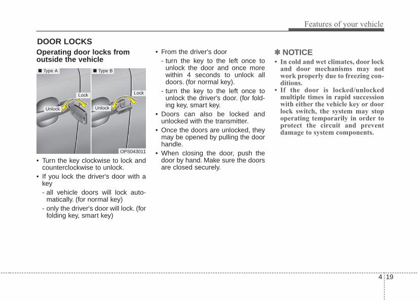
4 19
Features of your vehicle
DOOR LOCKS .Operating door locks fromoutside the vehicle
• Turn the key clockwise to lock andcounterclockwise to unlock.
• If you lock the driver's door with akey- all vehicle doors will lock auto-
matically. (for normal key)- only the driver's door will lock. (for
folding key, smart key)
• From the driver's door- turn the key to the left once to
unlock the door and once morewithin 4 seconds to unlock alldoors. (for normal key).
- turn the key to the left once tounlock the driver's door. (for fold-ing key, smart key.
• Doors can also be locked andunlocked with the transmitter.
• Once the doors are unlocked, theymay be opened by pulling the doorhandle.
• When closing the door, push thedoor by hand. Make sure the doorsare closed securely.
✽✽ NOTICE• In cold and wet climates, door lock
and door mechanisms may notwork properly due to freezing con-ditions.
• If the door is locked/unlockedmultiple times in rapid successionwith either the vehicle key or doorlock switch, the system may stopoperating temporarily in order toprotect the circuit and preventdamage to system components.
OPS043011
LockLock
Unlock
■ Type A ■ Type B
Unlock

Features of your vehicle
204
• To lock a door without the key,push the inside door lock button (1)or central door lock switch (2) tothe “Lock” position and close thedoor (3).
• If you lock the door with the centraldoor lock switch (2), all vehicledoors will lock automatically.
✽✽ NOTICEAlways remove the ignition key,engage the parking brake, close allwindows and lock all doors whenleaving your vehicle unattended.
Operating door locks frominside the vehicleWith the door lock button
• To unlock a door, push the doorlock button (1) to the “Unlock” posi-tion.The red mark (2) on the buttonwill be visible.
• To lock a door, push the door lockbutton (1) to the “Lock” position. Ifthe door is locked properly, the redmark (2) on the door lock buttonwill not be visible.
• To open a door, pull the door han-dle (3) outward.
• If the inner door handle of the dri-ver’s (or front passenger’s) door ispulled when the door lock button isin the lock position, the button willunlock and the door will open. (ifequipped)
• Front doors cannot be locked if theignition key is in the ignition switchand any front door is opened.
OPS043012
OPS043013
Lock Unlock

4 21
Features of your vehicle
If a power door lock ever fails to func-tion while you are in the vehicle, tryone or more of the following tech-niques to exit:• Operate the door unlock feature
repeatedly (both electronic andmanual) while simultaneouslypulling on the door handle.
• Operate the other door locks andhandles, front and rear.
• Lower a front window and use thekey to unlock the door from out-side.
• Move to the cargo area and openthe tailgate.
With central door lock switch
Operate by pressing the central doorlock switch.• When pressing the front portion (1)
of the switch, all vehicle doors willlock.
• When pressing the rear portion (2)of the switch, all vehicle doors willunlock.
• If the key is in the ignition switchand any front door is opened, thedoors will not lock even though thefront portion (1) of the central doorlock switch is pressed.
OPS043014
Driver’s door
OPS043015
Passenger’s door

Features of your vehicle
224
Impact sensing door unlock systemIn the event of air bag deploymentresulting from a vehicle impact, alldoors will automatically unlock.
Auto door lock/unlock feature(if equipped)• All doors will automatically lock
when the transaxle shift lever isshifted out of P(Park).
• All doors will automatically unlockwhen the transaxle shift lever isshifted into P (Park).
Speed sensing door lock sys-tem (if equipped)All doors will be automatically lockedafter the vehicle speed exceeds 15km/h (9.3 mph). And all doors will beautomatically unlocked when youturn the engine off or when youremove the ignition key.
✽✽ NOTICEYou can select some auto doorlock/unlock features in “UserSettings” as follows;• Speed sensing auto door lock• Auto door unlock when the igni-
tion key is removed from the igni-tion switch or engine is turned off.
• Auto door lock/unlock by shiftingthe shift lever out of P(Park) orinto P(Park).
For more information, refer to“User Settings” in this chapter.
WARNING- Unattended children/ani-
malsNever leave children or animalsunattended in your vehicle. Anenclosed vehicle can becomeextremely hot, causing death orsevere injury to unattendedchildren or animals who cannotescape the vehicle.
WARNING - DoorsThe doors should always befully closed and locked whilethe vehicle is in motion to pre-vent accidental opening of thedoor.

4 23
Features of your vehicle
Child-protector rear door lock
The child safety lock is provided tohelp prevent children from acciden-tally opening the rear doors frominside the vehicle. The rear doorsafety locks should be used whenev-er children are in the vehicle.1. Open the rear door.2. Push the child safety lock located
on the rear edge of the door to thelock ( ) position. When the childsafety lock is in the lock position, therear door will not open even whenthe inner door handle is pulled.
3. Close the rear door.To open the rear door, pull the out-side door handle.Even though the doors may beunlocked, the rear door will not openby pulling the inner door handle (1)until the rear door child safety lock isunlocked.
OPS043016
WARNING - Rear doorlocks
Use the rear door safety lockswhenever children are in thevehicle. If a child accidentlyopens the rear doors while thevehicle is motion, he can fall out.

Features of your vehicle
244
Opening the tailgate
• The tailgate is locked or unlockedwhen all doors are locked orunlocked with the key, transmitter(or smart key) or central door lockswitch.
• If unlocked, the tailgate can beopened by pressing the handleswitch and then pulling the handleup.
• Only the tailgate is unlocked if thetailgate unlock button on the smartkey is pressed (if equipped). Oncethe tailgate is opened and thenclosed, the tailgate is locked auto-matically.
✽✽ NOTICEIn cold and wet climates, door lockand door mechanisms may not workproperly due to freezing conditions.
The tailgate swings upward. Makesure no objects or people are nearthe rear of the vehicle when openingthe tailgate.
Closing the tailgate
To close the tailgate, lower and pushdown the tailgate firmly. Make surethat the tailgate is securely latched.Make sure your hands, feet andother parts of your body are safelyout of the way before closing the tail-gate.
TAILGATE
CAUTION - Tailgate liftMake certain that you close thetailgate before driving yourvehicle. Possible damage mayoccur to the tailgate lift cylin-ders and attached hardware ifthe tailgate is not closed prior todriving.
OPS043017 OPS043018

4 25
Features of your vehicle
Emergency tailgate safetyrelease
Your vehicle is equipped with anemergency tailgate safety releaselever located on the bottom of thetailgate. When someone is inadver-tently locked in the cargo area, thetailgate can be opened by pushingthe release lever and pushing openthe tailgate.
WARNING• No one should be allowed to
occupy the cargo area of thevehicle at any time. The cargoarea is a very dangerous loca-tion in the event of a crash.
• Use the release lever foremergencies only. Use withextreme caution, especiallywhile the vehicle is in motion.
OPS043019WARNING - Rear cargoarea
Occupants should never ride inthe rear cargo area where norestraints are available.Occupants should always beproperly restrained.
WARNING - Exhaustfumes
Driving with the tailgate open isnot advisable. Dangerousexhaust fumes can enter thepassenger compartment. If youmust drive with the tailgateopened, keep the air vents andall windows open so that addi-tional outside air can enter.

Features of your vehicle
264
(1) Driver’s door power windowswitch
(2) Front passenger’s door powerwindow switch
(3) Rear door (left) power windowswitch
(4) Rear door (right) power windowswitch
(5) Window opening and closing(6) Automatic power window
up/down(7) Power window lock switch
In cold and wet climates, power win-dows may not work properly due tofreezing conditions.
WINDOWS
OPS043020

4 27
Features of your vehicle
Power windowsThe ignition switch must be in the ONposition for power windows to operate.Each door has a power windowswitch that controls the door's win-dow. The driver has a power windowlock button which can block the oper-ation of the rear passenger windows.The power windows can be operatedfor approximately 30 seconds afterthe ignition key is removed or turnedto the ACC or LOCK position.However, if the front doors areopened, the power windows cannotbe operated even within the 30 sec-ond period.
✽✽ NOTICEWhile driving with the rear windowsdown or with the sunroof (ifequipped) in an open (or partiallyopen) position, your vehicle maydemonstrate a wind buffeting orpulsation noise. This noise is a nor-mal occurrence and can be reducedor eliminated by taking the follow-ing actions. If the noise occurs withone or both of the rear windowsdown, partially lower both frontwindows approximately one inch. Ifyou experience the noise with thesunroof open, slightly reduce thesize of the sunroof opening.
Window opening and closing
The driver’s door has a master powerwindow switch that controls all thewindows in the vehicle.To open or close a window, pressdown or pull up the front portion ofthe corresponding switch to the firstdetent position (5).
OPS043021
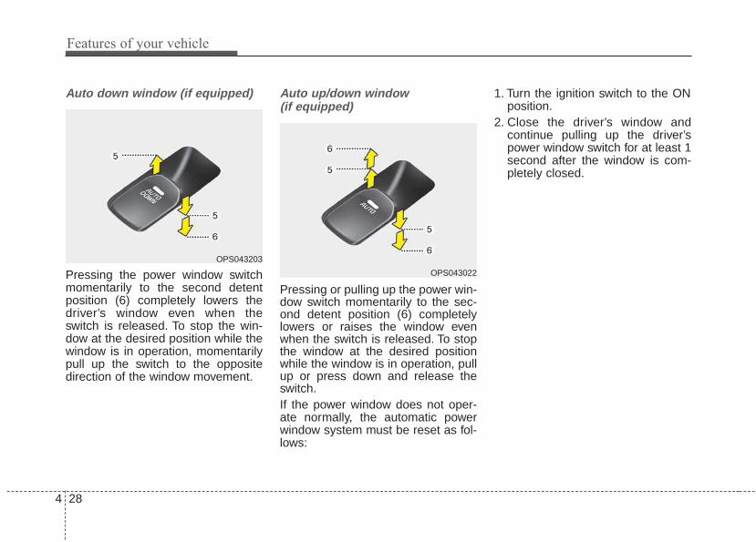
Features of your vehicle
284
Auto down window (if equipped)
Pressing the power window switchmomentarily to the second detentposition (6) completely lowers thedriver’s window even when theswitch is released. To stop the win-dow at the desired position while thewindow is in operation, momentarilypull up the switch to the oppositedirection of the window movement.
Auto up/down window (if equipped)
Pressing or pulling up the power win-dow switch momentarily to the sec-ond detent position (6) completelylowers or raises the window evenwhen the switch is released. To stopthe window at the desired positionwhile the window is in operation, pullup or press down and release theswitch.If the power window does not oper-ate normally, the automatic powerwindow system must be reset as fol-lows:
1. Turn the ignition switch to the ONposition.
2. Close the driver’s window andcontinue pulling up the driver’spower window switch for at least 1second after the window is com-pletely closed.
OPS043203
OPS043022

4 29
Features of your vehicle
Automatic reversal
If the upward movement of the win-dow is blocked by an object or part ofthe body, the window will detect theresistance and will stop upwardmovement. The window will thenlower approximately 30 cm (11.8 in.)to allow the object to be cleared.The distance may vary based on thesize or position of the window. If thewindow detects the resistance whilethe power window switch is pulled upcontinuously, the window will stopupward movement then lowerapproximately 2.5 cm (1 in.).
And if the power window switch ispulled up continuously again within 5seconds after the window is loweredby the automatic window reversalfeature, the automatic window rever-sal will not operate.The automatic reverse feature for thedriver’s window is only active whenthe “auto up” feature is used by fullypulling up the switch. The automaticreverse feature will not operate if thewindow is raised using the halfwayposition on the power window switch.
OUN026013
WARNING Always check for obstructionsbefore raising any window toavoid injuries or vehicle damage.If an object less than 0.16 in. (4mm) in diameter is caughtbetween the window glass andthe upper window channel, theautomatic reverse window maynot detect the resistance and willnot stop and reverse direction.

Features of your vehicle
304
Power window lock button
• The driver can disable the powerwindow switches on the passengerdoors by pressing the power win-dow lock button located on the dri-ver’s door to the LOCK position(pressed).
• When the power window lockswitch is pressed :- The driver's master control can
operate all the power windows.- The front passenger's control can
operate the front passenger'spower window.
- The rear passenger's control can-not operate the rear passenger'spower window.
OPS043023
CAUTION- Opening /closing Window
To prevent possible damage tothe power window system, donot open or close two windowsor more at the same time. Thiswill also ensure the longevity ofthe fuse.

4 31
Features of your vehicle
Always double check to make sureall arms, hands, head and otherobstructions are safely out of the waybefore closing a window.
WARNING- Power windows
Do not allow children to playwith the power windows. Keepthe power window lock switch(on the driver's door) in theLOCK (pressed) position.

Features of your vehicle
324
Opening the hood
1. Pull the release lever to unlatchthe hood. The hood should popopen slightly.
Open the hood after turning off theengine on a flat surface, shifting theshift lever to the P (Park) position forautomatic transaxle and to the 1st(First) gear or R (Reverse) for manu-al transaxle, and setting the parkingbrake.
2. Go to the front of the vehicle, raisethe hood slightly, pull the second-ary latch (1) inside of the hoodcenter and lift the hood (2).
3. Raise the hood. It will completelyrise by itself after it has beenraised about halfway.
Closing the hood1. Before closing the hood, check the
following:• All filler caps in the engine com-
partment must be correctlyinstalled.
2. Lower the hood halfway and pushdown to securely lock in place.
HOOD
OPS043024
OPS043025WARNING
Before closing the hood, ensurethat all obstructions areremoved from the hood open-ing. Closing the hood with anobstruction present in the hoodopening may result in severepersonal injury.

4 33
Features of your vehicle
When you check the engine com-partment, Take caution to avoid con-tacting your head with the safetyhook which is located inside of thehood.
WARNING - Fire riskDo not leave gloves, rags or anyother combustible material in theengine compartment. Doing somay cause a heat-induced fire.
WARNING - Unsecuredengine hood
Always double check to be surethat the hood is firmly latchedbefore driving away. If it is notlatched, the hood could fly openwhile the vehicle is being driv-en, causing a total loss of visi-bility, which might result in anaccident.
ODMNMC2034

Features of your vehicle
344
Opening the fuel filler lid
The fuel filler lid must be openedfrom inside the vehicle by pulling upthe fuel filler lid opener.If the fuel filler lid does not openbecause ice has formed around it,tap lightly or push on the lid to breakthe ice and release the lid. Do not pryon the lid. If necessary, spray aroundthe lid with an approved de-icer fluid(do not use radiator anti-freeze) ormove the vehicle to a warm placeand allow the ice to melt.
1. Stop the engine.2. To open the fuel filler lid, push the
fuel filler lid opener button.3. Pull open the fuel filler lid (1).4. To remove the cap, turn the fuel
filler cap (2) counterclockwise.5. Refuel as needed.
Closing the fuel filler lid1. To install the cap, turn it clockwise
until it “clicks” once. This indicatesthat the cap is securely tightened.
2. Close the fuel filler lid and push itin lightly making sure that it issecurely closed.
✽✽ NOTICEThere may be an intermittent noisenear the refueling hole while theengine is idling if the fuel cap is notclosed securely. This occurs normal-ly with the OBD system.
✽✽ NOTICEWhen refueling fully at an up hill,the fuel gauge may not point to the Fposition.It is not a malfunction. If you moveyour vehicle to a level ground, the fuelgauge will move to the full position.
FUEL FILLER LID
OPS043027
OPS043026

4 35
Features of your vehicle
Always check that the fuel cap isinstalled securely to prevent fuelspillage in the event of an accident.
✽✽ NOTICETighten the cap until it clicks once,otherwise the fuel cap open warningindicator light will illuminate
WARNING- Fire/explosion risk
Read and follow all warningsposted at the gas station facili-ty. Failure to follow all warningswill result in severe personalinjury, severe burns or deathdue to fire or explosion.
WARNING- Static electricity
• Before touching the fuel nozzle,you should eliminate potentiallydangerous static electricity dis-charge by touching anothermetal part of the vehicle, a safedistance away from the fuelfiller neck, nozzle, or other gassource.
• Do not get back into a vehicleonce you have begun refuelingsince you can generate staticelectricity by touching, rubbingor sliding against any item orfabric (polyester, satin, nylon,etc.) capable of producing staticelectricity. Static electricity dis-charge can ignite fuel vaporsresulting in rapid burning. If youmust reenter the vehicle, youshould once again eliminatepotentially dangerous staticelectricity discharge by touch-ing a metal part of the vehicle,away from the fuel filler neck,nozzle or other gasoline source.
WARNING - RefuelingAlways remove the fuel capcarefully and slowly. If the capis venting fuel or if you hear ahissing sound, wait until thecondition stops before com-pletely removing the cap.If pressurized fuel sprays out, itcan cover your clothes or skinand subject you to the risk offire and burns.

Features of your vehicle
364
Make sure to refuel your vehicleaccording to the “Fuel requirements”suggested in chapter 1.If the fuel filler cap requires replace-ment, use only a genuine Kia cap or theequivalent specified for your vehicle. Anincorrect fuel filler cap can result in aserious malfunction of the fuel systemor emission control system.
CAUTION - Exterior paintDo not spill fuel on the exteriorsurfaces of the vehicle. Anytype of fuel spilled on paintedsurfaces may damage the paint.
WARNING - Cell phonefires
Do not use cellular phones whilerefueling. Electric current and/orelectronic interference from cel-lular phones can potentiallyignite fuel vapors causing a fire.
WARNING - SmokingDO NOT use matches or a lighterand DO NOT SMOKE or leave a litcigarette in your vehicle while ata gas station especially duringrefueling. Automotive fuel ishighly flammable and can, whenignited, result in fire.
WARNING - Refueling &Vehicle fires
When refueling, always shut theengine off. Sparks produced byelectrical components relatedto the engine can ignite fuelvapors causing a fire. Oncerefueling is complete, check tomake sure the filler cap andfiller door are securely closed,before starting the engine.
WARNING - Portable fuelcontainer
When using an approvedportable fuel container, be sureto place the container on theground prior to refueling. Staticelectricity discharge from thecontainer can ignite fuel vaporscausing a fire. Once refuelinghas begun, contact with thevehicle should be maintaineduntil the filling is complete. Useonly approved portable plasticfuel containers designed tocarry and store gasoline.

4 37
Features of your vehicle
If your vehicle is equipped with asunroof, you can slide or tilt yoursunroof with the sunroof glass con-trol lever located on the overheadconsole (1).
The sunroof can only be opened,closed, or tilted when the ignitionswitch is in the ON position.
✽✽ NOTICE• In cold and wet climates, the sun-
roof may not work properly due tofreezing conditions.
• After a vehicle is washed or in arainstorm be sure to wipe off anywater that is on the sunroof beforeoperating it.
✽✽ NOTICEThe sunroof cannot tilt when it is inthe slide position but can be slidwhile in a tilt position.
PANORAMIC SUNROOF (IF EQUIPPED)
CAUTION - Sunroof control
Do not continue to pull or pushthe sunroof glass control leverafter the sunroof is fullyopened, closed, or tilted.Damage to the motor or systemcomponents could occur.
OPS043028
WARNING - Roof cargoDo not operate the sun roofwhile using the roof rack totransport cargo.This may causethe cargo to come loose anddistract the driver.
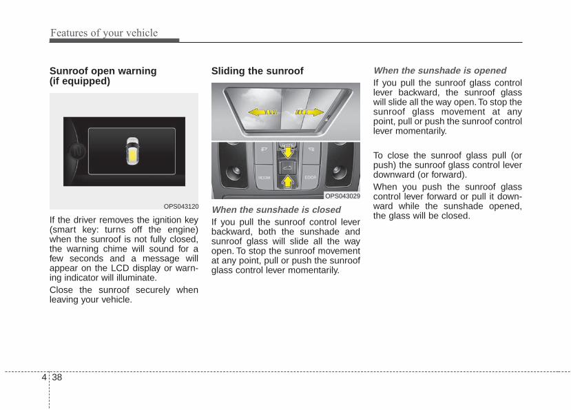
Features of your vehicle
384
Sunroof open warning (if equipped)
If the driver removes the ignition key(smart key: turns off the engine)when the sunroof is not fully closed,the warning chime will sound for afew seconds and a message willappear on the LCD display or warn-ing indicator will illuminate.Close the sunroof securely whenleaving your vehicle.
Sliding the sunroof
When the sunshade is closedIf you pull the sunroof control leverbackward, both the sunshade andsunroof glass will slide all the wayopen. To stop the sunroof movementat any point, pull or push the sunroofglass control lever momentarily.
When the sunshade is openedIf you pull the sunroof glass controllever backward, the sunroof glasswill slide all the way open.To stop thesunroof glass movement at anypoint, pull or push the sunroof controllever momentarily.
To close the sunroof glass pull (orpush) the sunroof glass control leverdownward (or forward).When you push the sunroof glasscontrol lever forward or pull it down-ward while the sunshade opened,the glass will be closed.
OPS043120
OPS043029

4 39
Features of your vehicle
Automatic reversal
If an object or part of the body isdetected while the sunroof is closingautomatically, it will reverse the direc-tion, and then stop.The auto reverse function does notwork if a tiny obstacle is between thesliding glass and the sunroof sash.You should always check that all pas-sengers and objects are away fromthe sunroof before closing it.
Tilting the sunroof
Before opening or closing the sun-roof, open the sunshade (refer to thefollowing page for instructions onhow to use the sunshade).To tilt up the sunroof - Push the sunroof glass control
lever upward.❈ When you push the sunroof glass
control lever upward while thesunshade closed, the sunshadewill be opened halfway and thenglass will be tilt up.
To tilt down (or close) the sunroof - Push the sunroof glass control
lever forward or pull it downwardWhen you push the sunroof glasscontrol lever forward or pull it down-ward while the sunshade opened,the glass will be tilt down.
OPS043030OXM049029

Features of your vehicle
404
Do not extend the face, neck, armsor body outside the sunroof whiledriving.
Sunshade
To open the sunshadePress the sunshade open button (1).To stop the sliding at any point, pressthe sunshade control switch momen-tarily.
CAUTION - Sunroof motordamage
If you try to open the sunroofwhen the temperature is belowfreezing or when the sunroof iscovered with snow or ice, theglass or the motor could bedamaged.
CAUTIONPeriodically remove any dirt thatmay accumulate on the guiderail to prevent damage to thesunroof.
OPS043031
WARNING - SunroofOperation
When closing the sunroof, makesure there are no body parts inthe movement range of the slid-ing roof. Parts of the body couldbecome trapped or crushed.
4 41
Features of your vehicle
To close the sunshade when thesunroof glass is closed- Press the sunshade close button
(2).❈ When you press the sunshade
close button (2) with the sunroofglass opened
The sunshade will be closedhalfway, then sunroof glass will beclosed and then sunshade will befully closed finally.
To stop the sliding at any point, pressthe sunshade control switch momen-tarily.
✽✽ NOTICEWrinkles formed on the sunshade asmaterial characteristic are normal.
Resetting the sunroofWhenever the vehicle battery is dis-connected or discharged, you mustreset your sunroof system as follows:
1.Turn the ignition switch to the ONposition.
2.Close the sunshade and sunroofcompletely if opened.
3.Release the sunroof control lever.4.Push the sunroof control lever for-
ward in the direction of close (about10 seconds) until the sunroof movesa little. Then, release the lever.
CAUTION - Automatic sunroof shade
• Do not pull or push the sun-shade by hand as such actionmay damage the sunshade orcause it to malfunction.
• Close the sunroof when driv-ing in dusty environments.Dust may cause a malfunctionof the vehicle system.
Features of your vehicle
424
5.Push the sunroof control lever for-ward in the direction of close, untilthe sunroof operates as followsagain:
The sunshade and sunroof glassslide open → The sunroof glassslide close → The sunshade close
Then, release the lever.
When this is complete, the sunroofsystem has been reset.
✽✽ NOTICEIf you do not reset the sunroof, itmay not work properly.
4 43
Features of your vehicle
Electric power steering (EPS)The power steering uses a motor toassist you in steering the vehicle. Ifthe engine is off or if the power steer-ing system becomes inoperative, thevehicle may still be steered, but it willrequire increased steering effort.The motor driven power steering iscontrolled by a power steering con-trol unit which senses the steeringwheel torque and vehicle speed tocommand the motor.The steering becomes heavier asthe vehicle’s speed increases andbecomes lighter as the vehicle’sspeed decreases for optimum steer-ing control.Should you notice any change in theeffort required to steer during normalvehicle operation, have the powersteering checked by an authorizedKia dealer.
• If the Electric Power SteeringSystem does not operate normally,the warning light will illuminate onthe instrument cluster.The steeringwheel may require increasedsteering effort. Take your vehicle toan authorized Kia dealer and havethe vehicle checked as soon aspossible.
• When you operate the steeringwheel in low temperature, noisemay occur. If temperature rises, thenoise will likely disappear. This is anormal condition.
• When the vehicle is stationary,when the steering wheel is turnedall the way to the left or right con-tinuously, the steering wheelbecomes harder to turn. The powerassist is limited to protect themotor from overheating.As time passes, the steering wheelreturn to its normal condition.
✽✽ NOTICEThe following symptoms may occurduring normal vehicle operation:• The EPS warning light does not
illuminate.• The steering gets heavy immedi-
ately after turning the ignitionswitch on. This happens as the sys-tem performs the EPS systemdiagnostics. When the diagnosticsare completed, the steering wheelwill return to its normal condition.
• A click noise may be heard fromthe EPS relay after the ignitionswitch is turned to the ON orLOCK (OFF) position.
• A motor noise may be heard whenthe vehicle is at a stop or at a lowdriving speed.
(Continued)
STEERING WHEEL

Features of your vehicle
444
(Continued)• If the Electric Power Steering
System does not operate normally,the warning light will illuminate onthe instrument cluster. The steer-ing wheel may become difficult tocontrol or operate abnormally.Take your vehicle to an authorizedKia dealer and have the vehiclechecked as soon as possible.
• When you operate the steeringwheel in low temperature, abnor-mal noise may occur. If tempera-ture rises, the noise will likely dis-appear. This is a normal condition.
• When the charging system warn-ing light comes on due to the lowvoltage (When the alternator orbattery) does not operate normal-ly or it malfunctions), the steeringwheel may require increasedsteering effort.
Tilt and telescopic steering Tilt and telescopic steering allowsyou to adjust the steering wheelbefore you drive.You can also raise itto give your legs more room whenyou exit and enter the vehicle.
The steering wheel should be posi-tioned so that it is comfortable foryou to drive, while permitting you tosee the instrument panel warninglights and gauges.
To change the steering wheel angle,pull down the lock-release lever (1),adjust the steering wheel to thedesired angle (2) and height (3, ifequipped) then pull up the lock-release lever to lock (4) the steeringwheel in place. Be sure to adjust thesteering wheel to the desired posi-tion before driving.
OPS043032
WARNING - Steeringwheel adjustment
Never adjust the angle andheight of the steering wheelwhile driving. You may losesteering control.

4 45
Features of your vehicle
Heated steering wheel (if equipped)
With the ignition switch in the ONposition, pressing the heated steer-ing wheel button warms the steeringwheel. The indicator on the buttonwill illuminate.To turn the heated steering wheel off,press the button once again. Theindicator on the button will turn off.
✽✽ NOTICEThe heated steering wheel will turnoff automatically approximately 30minutes after the heated steeringwheel is turned on.
OPS045033N
CAUTION• Do not install any grip to oper-
ate the steering wheel. Thiscauses damage to the heatedsteering wheel system.
• When cleaning the heatedsteering wheel, do not use anorganic solvent such as paintthinner, benzene, alcohol andgasoline. Doing so may dam-age the surface of the steeringwheel.
• If the surface of steeringwheel is damaged by sharpobject, damage to the heatedsteering wheel componentscould occur.
WARNINGIf the steering wheel becomestoo warm, turn the system off.The heated steering wheel maycause burns even at low tem-peratures, especially if used forlong periods of time.

Features of your vehicle
464
Horn
To sound the horn, press the hornsymbols on your steering wheel.Check the horn regularly to be sure itoperates properly.
✽✽ NOTICETo sound the horn, press the areaindicated by the horn symbol onyour steering wheel (see illustra-tion). The horn will operate onlywhen this area is pressed.
FLEX STEER
The FLEX STEER controls steeringeffort based upon as driver's prefer-ence or road condition.You can select the desired steeringmode by pressing the FLEX STEERbutton.
When the steering mode button ispressed, the selected steering modewill appear on the instrument cluster.If the steering mode button is pressedwithin 4 seconds, the steering modewill change as shown above.If the steering wheel mode button isnot pressed for about 4 seconds, theLCD display will change to the previ-ous screen (for Type B cluster).
OPS043036
OPS043209
OPS043034

4 47
Features of your vehicle
Normal mode
The normal mode offers mediumsteering effort.
Sport mode
The steering wheel becomes heav-ier. The sport mode is usually usedwhen driving on the highway.
Comfort mode
The steering wheel becomes lighter.The comfort mode is usually usedwhen driving in the city or when park-ing the vehicle.
OPS043129 OPS043130 OPS043131

Features of your vehicle
484
• For your safety, if you press thesteering mode button while operat-ing the steering wheel, but thesteering effort will not changeimmediately. After operating thesteering wheel, the steering effortwill change automatically to theselected mode.
• Use caution when changing thesteering mode while driving.
• When the electronic power steer-ing is not operating properly, theflex steering wheel will not work.

4 49
Features of your vehicle
MIRRORSInside rearview mirrorAdjust the rearview mirror so that thecenter view through the rear windowis seen. Make this adjustment beforeyou start driving.Do not place objects in the rear seator cargo area which would interferewith your vision through the rear win-dow.
Day/night rearview mirror (if equipped)
Make this adjustment before youstart driving and while the day/nightlever is in the day position.Pull the day/night lever toward you toreduce the glare from the headlightsof the vehicles behind you duringnight driving.Remember that you lose somerearview clarity in the night position.
WARNING - Mirror adjustment
Do not adjust the rearview mir-ror while the vehicle is moving.This could result in loss of con-trol.
WARNING Do not modify the inside mirrorand don’t install a wide mirror. Itcould result in injury, during anaccident or deployment of theair bag.
OAM049023
Day
Night
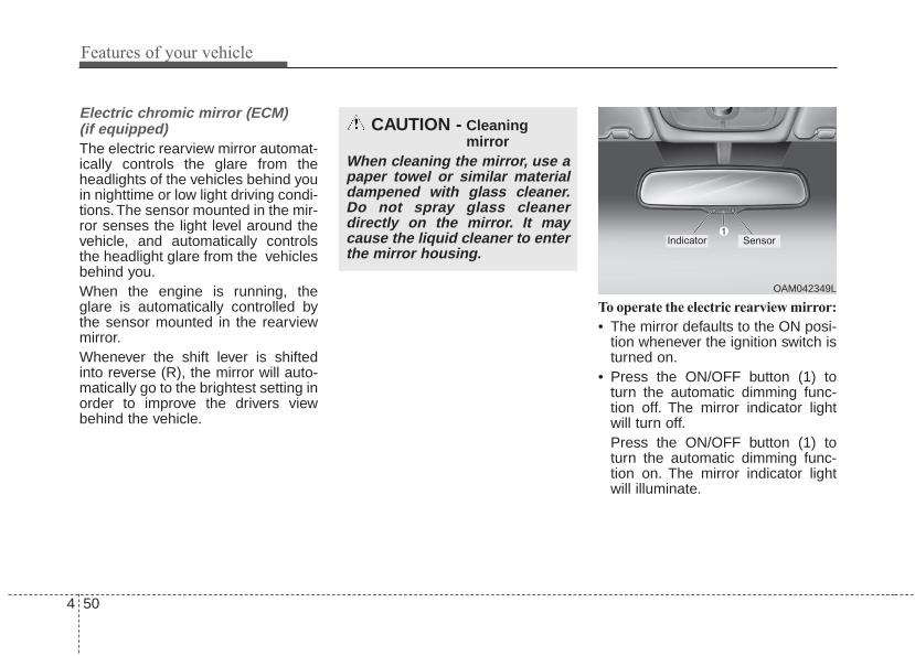
Features of your vehicle
504
Electric chromic mirror (ECM) (if equipped)The electric rearview mirror automat-ically controls the glare from theheadlights of the vehicles behind youin nighttime or low light driving condi-tions.The sensor mounted in the mir-ror senses the light level around thevehicle, and automatically controlsthe headlight glare from the vehiclesbehind you.When the engine is running, theglare is automatically controlled bythe sensor mounted in the rearviewmirror.Whenever the shift lever is shiftedinto reverse (R), the mirror will auto-matically go to the brightest setting inorder to improve the drivers viewbehind the vehicle.
To operate the electric rearview mirror:
• The mirror defaults to the ON posi-tion whenever the ignition switch isturned on.
• Press the ON/OFF button (1) toturn the automatic dimming func-tion off. The mirror indicator lightwill turn off.Press the ON/OFF button (1) toturn the automatic dimming func-tion on. The mirror indicator lightwill illuminate.
CAUTION - Cleaning mirror
When cleaning the mirror, use apaper towel or similar materialdampened with glass cleaner.Do not spray glass cleanerdirectly on the mirror. It maycause the liquid cleaner to enterthe mirror housing.
OAM042349L
Indicator Sensor

4 51
Features of your vehicle
Outside rearview mirror Be sure to adjust the mirror anglesbefore driving.Your vehicle is equipped with bothleft-hand and right-hand outsiderearview mirrors. The mirrors can beadjusted remotely with the remoteswitch. The mirror heads can be fold-ed back to prevent damage during anautomatic vehicle wash or whenpassing through a narrow street.The right outside rearview mirror isconvex. Objects seen in the mirrorare closer than they appear.Use your interior rearview mirror ordirect observation to determine theactual distance of following vehicleswhen changing lanes.
If the mirror is jammed with ice, donot adjust the mirror by force. Use anapproved spray de-icer (not radiatorantifreeze) to release the frozenmechanism or move the vehicle to awarm place and allow the ice to melt.
CAUTION - Rearview mirror
Do not scrape ice off the mirrorface; this may damage the sur-face of the glass. If ice shouldrestrict the movement of the mir-ror, do not force the mirror foradjustment. To remove ice, use adeicer spray, or a sponge or softcloth with very warm water.
WARNING- Mirror adjustment
Do not adjust or fold the outsiderearview mirrors while the vehi-cle is moving. This could resultin loss of control.

Features of your vehicle
524
Remote control
Electric type
The electric remote control mirrorswitch allows you to adjust the positionof the left and right outside rearviewmirrors. To adjust the position of eithermirror the ignition switch should be inthe ACC position. Move the switch (1)to R or L to select the right side mirroror the left side mirror, then press a cor-responding point on the mirror adjust-ment control to position the selectedmirror up, down, left or right.After the adjustment, put the switchinto the neutral (center) position toprevent inadvertent adjustment.
Folding the outside rearview mirror
Manual type
To fold the outside rearview mirror,grasp the housing of the mirror andthen fold it toward the rear of thevehicle.
OPS043035
CAUTION - Outside mirror• The mirrors stop moving when
they reach the maximumadjusting angles, but themotor continues to operatewhile the switch is pressed.Do not press the switch longerthan necessary, the motormay be damaged.
• Do not attempt to adjust theoutside rearview mirror byhand. Doing so may damagethe parts.
OPS043037
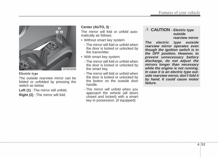
4 53
Features of your vehicle
Electric type
The outside rearview mirror can befolded or unfolded by pressing theswitch as below.Left (1) : The mirror will unfold.Right (2) : The mirror will fold.
Center (AUTO, 3) :The mirror will fold or unfold auto-matically as follows:• Without smart key system
- The mirror will fold or unfold whenthe door is locked or unlocked bythe transmitter.
• With smart key system- The mirror will fold or unfold when
the door is locked or unlocked bythe smart key.
- The mirror will fold or unfold whenthe door is locked or unlocked bythe button on the outside doorhandle.
- The mirror will unfold when youapproach the vehicle (all doorsclosed and locked) with a smartkey in possession. (if equipped)
CAUTION - Electric typeoutsiderearview mirror
The electric type outsiderearview mirror operates eventhough the ignition switch is inthe OFF position. However, toprevent unnecessary batterydischarge, do not adjust themirrors longer than necessarywhile the engine is not running.In case it is an electric type out-side rearview mirror, don’t fold itby hand. It could cause motorfailure.
OPS043038

Features of your vehicle
544
INSTRUMENT CLUSTER
1. Tachometer
2. Speedometer
3. Engine coolant temperature gauge
4. Fuel gauge
5. LCD display
6. Warning and indicator lights (if equipped)
7. Turn signal indicator lights
OPS043100C/OPS045101C
■■ Type A
❈ The actual cluster in the vehicle may differfrom the illustration.For more details, refer to the "Gauges" inthis chapter.
■■ Type B

4 55
Features of your vehicle
Instrument Cluster ControlAdjusting Instrument ClusterIllumination
The brightness of the instrumentpanel illumination is changed bypressing the illumination control button("+" or "-") when the ignition switch orEngine Start/Stop button is ON, or thetale lights are turned on. • If you hold the illumination control
button ("+" or "-"), the brightnesswill be changed continuously.
• If the brightness reaches to themaximum or minimum level, analarm will sound.
LCD Display Control
The LCD display modes can bechanged by using the control buttonson the steering wheel.
OPS043039
OPS043117
OTF044112L
■ Type A
■ Type BOPS043202
OPS043040
■ Type A
■ Type B

Features of your vehicle
564
[For type A cluster](1) TRIP : TRIP button for changing
trip modes(2) RESET : RESET button for
resetting items
[For type B cluster](1) : MODE button for changing
modes or SELECT buttonfor setting the selected item
(2) : MOVE button for changingitems or RESET button forresetting the selected item
❈ For the LCD modes, refer to “LCDDisplay” in this chapter.
GaugesSpeedometer
The speedometer indicates thespeed of the vehicle and is calibratedin miles per hour (mph) and/or kilo-meters per hour (km/h).
Tachometer
The tachometer indicates theapproximate number of engine revo-lutions per minute (rpm).
OPS043102N
OPS043103C
■ Type A
■ Type B
OPS043104N
OPS043106
■ Type A
■ Type B

4 57
Features of your vehicle
Use the tachometer to select the cor-rect shift points and to prevent lug-ging and/or over-revving the engine.
Engine Coolant TemperatureGauge
This gauge indicates the tempera-ture of the engine coolant when theignition switch or Engine Start/Stopbutton is ON.
If the gauge pointer moves beyondthe normal range area toward the “H”position, it indicates overheating thatmay damage the engine.Do not continue driving with an over-heated engine. If your vehicle over-heats, refer to “If the EngineOverheats” in chapter 6.
CAUTION - Red zoneDo not operate the engine with-in the tachometer's RED ZONE.This may cause severe enginedamage.
OPS043108
OPS043109
■ Type A
■ Type B
WARNING - Hot radiatoNever remove the radiator capwhen the engine is hot. Theengine coolant is under pressureand could severely burn. Waituntil the engine is cool beforeadding coolant to the reservoir.
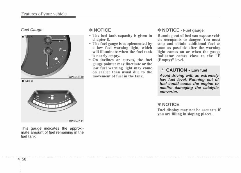
Features of your vehicle
584
Fuel Gauge
This gauge indicates the approxi-mate amount of fuel remaining in thefuel tank.
✽✽ NOTICE• The fuel tank capacity is given in
chapter 8.• The fuel gauge is supplemented by
a low fuel warning light, whichwill illuminate when the fuel tankis nearly empty.
• On inclines or curves, the fuelgauge pointer may fluctuate or thelow fuel warning light may comeon earlier than usual due to themovement of fuel in the tank.
✽✽ NOTICE - Fuel gaugeRunning out of fuel can expose vehi-cle occupants to danger. You muststop and obtain additional fuel assoon as possible after the warninglight comes on or when the gaugeindicator comes close to the "E(Empty)" level.
✽✽ NOTICEFuel display may not be accurate ifyou are filling in sloping places.
OPS043110
OPS043111
■ Type A
■ Type B
CAUTION - Low fuelAvoid driving with an extremelylow fuel level. Running out offuel could cause the engine tomisfire damaging the catalyticconverter.
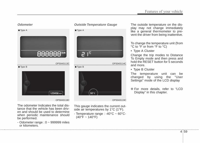
4 59
Features of your vehicle
Odometer
The odometer Indicates the total dis-tance that the vehicle has been driv-en and should be used to determinewhen periodic maintenance shouldbe performed.- Odometer range : 0 ~ 999999 miles
or kilometers.
Outside Temperature Gauge
This gauge indicates the current out-side air temperatures by 1°C (1°F).- Temperature range : -40°C ~ 60°C-
(40°F ~ 140°F)
The outside temperature on the dis-play may not change immediatelylike a general thermometer to pre-vent the driver from being inattentive.
To change the temperature unit (from°C to °F or from °F to °C)• Type A ClusterChange the trip modes to DistanceTo Empty mode and then press andhold the RESET button for 5 secondsand more.• Type B Cluster The temperature unit can bechanged by using the "UserSettings" mode of the LCD display
❈ For more details, refer to “LCDDisplay” in this chapter.
OPS043113C
OPS043118C
■ Type A
■ Type B
OPS043114C
OPS043119C
■ Type A
■ Type B

Features of your vehicle
604
Transaxle Shift IndicatorAutomatic Transaxle Shift Indicator
This indicator displays which auto-matic transaxle shift lever is selected.
• Park : P• Reverse : R• Neutral : N• Drive : D• Sports Mode : 1, 2, 3, 4, 5, 6
Manual Transaxle Shift Indicator(if equipped)
This indicator informs which gear isdesired while driving to save fuel.
• Shifting up : ▲2, ▲3, ▲4, ▲5, ▲6• Shifting down : ▼1, ▼2, ▼3, ▼4, ▼5
OPS043115
OTF044125L
■ Type A
■ Type B
OPS043116
OTF044402
■ Type A
■ Type B

4 61
Features of your vehicle
For example: Indicates that shifting up to the3rd gear is desired (currentlythe shift lever is in the 2nd or 1stgear).
: Indicates that shifting down tothe 3rd gear is desired (current-ly the shift lever is in the 4th, 5th,or 6th gear).
When the system is not working prop-erly, the indicator is not displayed.

Features of your vehicle
624
LCD Modes (for type B cluster)LCD DISPLAY (IF EQUIPPED)
Modes Symbol Explanation
Trip Computer This mode displays driving information like the tripmeter, fuel economy, and so on.For more details, refer to “Trip Computer” in this chapter.
Turn By Turn(if equipped)
This mode displays the state of the navigation.
LDWS(if equipped)
This mode displays the state of the Lane Departure Warning System (LDWS).For more details, refer to "Lane Departure Warning System (LDWS)" in chapter 5.
A/V(if equipped)
This mode displays the state of the A/V system.
ServiceThis mode informs of service interval (mileage or days) and warning messagesrelated to TPMS and so on.
Master warning
User Settings On this mode, you can change settings of the doors, lamps, and so on.
❈ For controlling the LCD modes, refer to "LCD Display Control" in this chapter.

4 63
Features of your vehicle
Service ModeService Interval
Service in
It calculates and displays when youneed a scheduled maintenanceservice (mileage or days).If the remaining mileage or timereaches 1,500 km (900 mi.) or 30days, "Service in" message is dis-played for several seconds each timeyou set the ignition switch or EngineStart/Stop Button to the ON position.
Service required
If you do not have your vehicle serv-iced according to the already inputtedservice interval, “Service required”message is displayed for several sec-onds each time you set the ignitionswitch or Engine Start/Stop Button tothe ON position (The mileage andtime changes to "---").To reset the service interval to themileage and days you inputted before:- Press the RESET button for
more than 1 second.
Service in OFF
If the service interval is not set,“Service in OFF” message is dis-played on the LCD display.
✽✽ NOTICE If any of the following conditionsoccurs, the mileage and days may beincorrect.- The battery cable is disconnected.- The fuse switch is turned off.- The battery is discharged.
OPS043134C
OTF044196L OTF044192L

Features of your vehicle
644
Master Warning Mode (if equipped)
• This warning light informs the driv-er the following situations- Service reminder (if equipped)- Forward collision warning system
(FCWS) malfunction (if equipped)The Master Warning Light illumi-nates when more than one of theabove warning situations occur. Atthis time, the LCD Modes Icon willchange from ( ) to ( ).If the warning situation is solved, theLCD Modes Icon will be changed backto its previous icon ( ).
User Settings ModeDescription
On this mode, you can change set-ting of the doors, lamps, and so on.
DoorAuto Door Lock (if equipped)
• Off:The auto door lock operation willbe deactivated.
• Speed (for manual transaxle)All doors will be automaticallylocked when the vehicle speedexceeds 15km/h (9.3mph).
• Shift Lever:All doors will be automaticallylocked if the automatic transaxleshift lever is shifted from the P(Park) position to the R (Reverse),N (Neutral), or D (Drive) position.
Auto Door Unlock (if equipped)
• Off:The auto door unlock operation willbe canceled.
• Key Out or Power Off:All doors will be automaticallyunlocked when the ignition key isremoved from ignition switch orEngine Start/Stop Button is set tothe OFF position.
OPS043132

4 65
Features of your vehicle
• Shift Lever:All doors will be automaticallyunlocked if the automatic transaxleshift lever is shifted to the P (Park)position.
Two Press Unlock (if equipped)
• Off:The two press unlock function willbe deactivated.Therefore, all doorswill unlock if the door is unlocked.
• On:The driver’s door will unlock if thedoor is unlocked. When the door isunlocked again within 4 seconds,all doors will unlock.
Horn Feedback (if equipped)
• Off:The Horn feedback operation willbe deactivated.
• On:After locking the door by pressingthe lock button on the transmitter, ifyou press the lock button againwithin 4 seconds, the warningsound will operate once to indicatethat all doors are locked.
LampOne Touch Turn Lamp (if equipped)
If this item is checked, the lanechange signals will blink 3, 5 or 7times when the turn signal lever ismoved slightly.
Head Lamp Delay (if equipped)
If this item is checked, the headlampdelay function will be activated.
SettingsLanguage
Choose the language you preferwithin the LCD.
Temperature Unit
Convert the temperature unit from °Cto °F or from °F to °C.
Welcome Sound
If this item is checked, the welcomesound function will be activated.
Fuel economy auto reset
• Auto Reset:The average fuel economy willreset automatically when refueling.
• Manual Reset:The average fuel economy will notreset automatically whenever refu-eling.
For more details, refer to “TripComputer” in this chapter.
Forward Collision Warning (if equipped)
If this item is checked, forward collisionwarning function will be activated.

Features of your vehicle
664
Service Interval
On this mode, you can activate theservice interval function with mileage(mi. or km) and period (months).
A/V Mode (if equipped)
This mode displays the state of theA/V system.
Turn By Turn Mode (if equipped)
This mode displays the state of thenavigation.
OTF044129OPS043133C OPS043208C

4 67
Features of your vehicle
Warning MessagesShift to "P" position (for smart keysystem and automatic transaxle)
• This warning message illuminates ifyou try to turn off the engine withoutthe shift lever in P (Park) position.
• At this time, the Engine Start/StopButton turns to the ACC position (Ifyou press the Engine Start/StopButton once more, it will turn to theON position).
Low Key Battery (for smart key system)
• This warning message illuminatesif the battery of the smart key isdischarged when the EngineStart/Stop Button changes to theOFF position.
Press brake pedal to start engine (for smart key system and auto-matic transaxle)
• This warning message illuminatesif the Engine Start/Stop Buttonchanges to the ACC position twiceby pressing the button repeatedlywithout depressing the brake pedal.
• It means that you should depressthe brake pedal to start the engine.
OTF044148L
OTF044142L
OTF044152L

Features of your vehicle
684
Press clutch pedal to start engine(for smart key system and manualtransaxle)
• This warning message illuminates ifthe Engine Start/Stop Buttonchanges to the ACC position twiceby pressing the button repeatedlywithout depressing the clutch pedal.
• It means that you should depressthe clutch pedal to start the engine.
Key not in vehicle (for smart key system)
• This warning message illuminatesif the smart key is not in the vehiclewhile the door is opened or closedwith the ignition switch in the ACCposition or engine is running.
• It means that you should alwayshave the smart key with you.
Key not detected (for smart key system)
• This warning message illuminatesif the smart key is not detectedwhen you press the EngineStart/Stop Button.
OTF044190L
OTF044138L OTF044140L
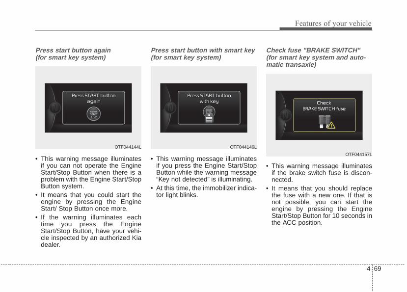
4 69
Features of your vehicle
Press start button again (for smart key system)
• This warning message illuminatesif you can not operate the EngineStart/Stop Button when there is aproblem with the Engine Start/StopButton system.
• It means that you could start theengine by pressing the EngineStart/ Stop Button once more.
• If the warning illuminates eachtime you press the EngineStart/Stop Button, have your vehi-cle inspected by an authorized Kiadealer.
Press start button with smart key (for smart key system)
• This warning message illuminatesif you press the Engine Start/StopButton while the warning message“Key not detected” is illuminating.
• At this time, the immobilizer indica-tor light blinks.
Check fuse "BRAKE SWITCH" (for smart key system and auto-matic transaxle)
• This warning message illuminatesif the brake switch fuse is discon-nected.
• It means that you should replacethe fuse with a new one. If that isnot possible, you can start theengine by pressing the EngineStart/Stop Button for 10 seconds inthe ACC position.
OTF044146LOTF044144L
OTF044157L

Features of your vehicle
704
Shift to "P" or "N" to start engine (for smart key system and auto-matic transaxle)
• This warning message illuminatesif you try to start the engine withthe shift lever not in the P (Park) orN (Neutral) position.
✽✽ NOTICEYou can start the engine with theshift lever in the N (Neutral) position.But, for your safety, we recommendthat you start the engine with theshift lever in the P (Park) position.
Door Open
• It means that any door is open.
Tailgate Open
• It means that the tailgate is open.OTF044150L
OPS043121 OPS043122

4 71
Features of your vehicle
Sunroof Open (if equipped)
• The warning message illuminatesif you turn off the engine when thesunroof is open.
Turn on "FUSE SWITCH" (if equipped)
• This warning message illuminatesif the fuse switch on the fuse box isOFF.
• The "FUSE" and "on" warningmessages are displayed alternate-ly. (for Type A)
• It means that you should turn thefuse switch on.
For more details, refer to “Fuses” inchapter 7.
OPS043120
OPS044309L
OPS043405L
■ Type A
■ Type B

Features of your vehicle
724
Tripmeter A
Tripmeter B
Range
Average Fuel Economy*
Average Vehicle Speed*
Elapsed Time*
* if equipped
To change the trip mode, press theTRIP button.
Low Washer Fluid (if equipped)
• This warning message illuminateson the service reminder mode ifthe washer fluid level in the reser-voir is nearly empty.
• It means that you should refill thewasher fluid.
OverviewDescriptionThe trip computer is a microcomput-er-controlled driver information sys-tem that displays information relatedto driving.
✽✽ NOTICESome driving information stored inthe trip computer (for exampleAverage Vehicle Speed) resets if thebattery is disconnected.
Trip Modes (for Type A cluster)TRIP COMPUTER
OTF044159L

4 73
Features of your vehicle
Trip Modes (for Type B cluster) Trip A/B Tripmeter (1)• The tripmeter is the total driving dis-
tance since the last tripmeter reset.- Distance range: 0.0 ~ 9999.9 mi.
or km• To reset the tripmeter, press the
RESET/ button on the steeringwheel for more than 1 secondwhen the tripmeter is displayed.
Average Vehicle Speed (2)• The average vehicle speed is cal-
culated by the total driving dis-tance and driving time since thelast average vehicle speed reset.- Speed range: 160 MPH or 200
km/h• To reset the average vehicle speed,
press the RESET/ button on thesteering wheel for more than 1 sec-ond when the average vehiclespeed is displayed.
• Tripmeter [A]
• Average Vehicle Speed [A]
• Elapsed Time [A]
TRIP A
• Tripmeter [B]
• Average Vehicle Speed [B]
• Elapsed Time [B]
TRIP B
• Range
• Average Fuel Economy
• Instant Fuel Economy
FUEL ECONOMY
To change the trip mode, press theMOVE button .
■ Type A
OPS043125C
OPS043127C
■ Type B

Features of your vehicle
744
✽✽ NOTICE• The average vehicle speed is not dis-
played if the driving distance is lessthan 50 meters (0.03 miles) or thedriving time is less than 10 secondssince the ignition switch or EngineStart/Stop button is turned to ON.
• Even if the vehicle is not in motion,the average vehicle speed keepsgoing while the engine is running.
Elapsed Time (3)• The elapsed time is the total driv-
ing time since the last elapsed timereset.- Time range (hh:mm): 00:00 ~ 99:59
• To reset the elapsed time, pressthe RESET/ button on the steer-ing wheel for more than 1 secondwhen the elapsed time is dis-played.
✽✽ NOTICEEven if the vehicle is not in motion,the elapsed time keeps going whilethe engine is running.
Fuel EconomyRange (1)
• The range to empty is the estimat-ed distance the vehicle can bedriven with the remaining fuel.- Distance range : 30 ~ 1999 mi or
50 ~ 1999 km.
• If the estimated distance is below50 km (30 mi.), the trip computerwill display “---” as distance toempty.
• If the vehicle is not on level groundor the battery power has beeninterrupted, the distance to emptyfunction may not operate correctly.
• The distance to empty may differfrom the actual driving distance asit is an estimate of the availabledriving distance.
• The trip computer may not registeradditional fuel if less than 1.6 gal-lons (6 liters ) of fuel are added tothe vehicle.
• The fuel economy and distance toempty may vary significantly basedon driving conditions, drivinghabits, and condition of the vehicle.
■ Type A
OPS043123C
OPS043128C
■ Type B

4 75
Features of your vehicle
Average Fuel Economy (2)• The average fuel economy is calcu-
lated by the total driving distanceand fuel consumption since the lastaverage fuel economy reset.- Fuel economy range: 0.0 ~ 99.9
MPG or L/100km• The average fuel economy can be
reset both manually and automati-cally.
Manual reset
To clear the average fuel economymanually, press the RESET/ but-ton on the steering wheel for morethan 1 second when the average fueleconomy is displayed.
Automatic reset
To make the average fuel economybe reset automatically whenever refu-eling, select the “Auto Reset” mode inUser Setting menu of the LCD display(Refer to “LCD Display”).Under “Auto Reset” mode, the aver-age fuel economy will be cleared tozero (---) when the vehicle speedexceeds 1 km/h after refueling morethan 1.6 gallons (6 liters).
✽✽ NOTICEThe average fuel economy is not dis-played for more accurate calculationif the vehicle does not drive morethan 10 seconds or 0.03 miles (50meters) since the ignition switch orEngine Start/Stop button is turnedto ON.
Instant Fuel Economy (3)• This mode displays the instant fuel
economy during the last few sec-onds when the vehicle speed ismore than 10 km/h (6.2 MPH).- Fuel economy range: 0 ~ 99.9
MPG or L/100km

Features of your vehicle
764
Warning lights
✽✽ NOTICE - Warning lightsMake sure that all warning lightsare OFF after starting the engine. Ifany light is still ON, this indicates asituation that needs attention.
Air bag Warning Light
This warning light illuminates:
• Once you set the ignition switch orEngine Start/Stop Button to the ONposition.- It illuminates for approximately 6
seconds and then goes off.• When there is a malfunction with
the SRS.In this case, have your vehicleinspected by an authorized Kiadealer.
Seat Belt Warning Light
This warning light informs the driverthat the seat belt is not fastened.For more details, refer to the “SeatBelts” in chapter 3.
WARNING AND INDICATOR LIGHTS
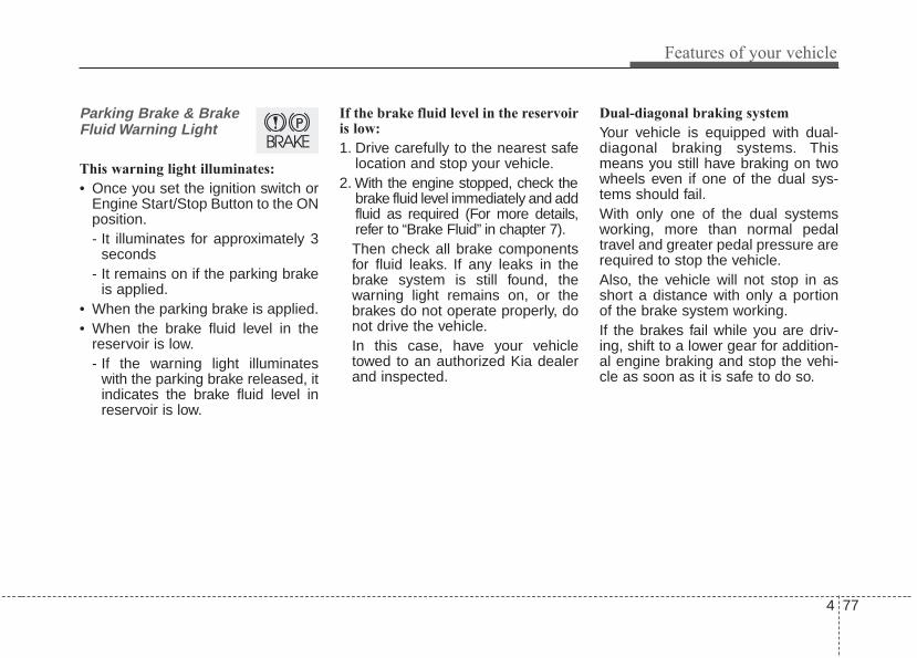
4 77
Features of your vehicle
Parking Brake & BrakeFluid Warning Light
This warning light illuminates:
• Once you set the ignition switch orEngine Start/Stop Button to the ONposition.- It illuminates for approximately 3
seconds- It remains on if the parking brake
is applied.• When the parking brake is applied.• When the brake fluid level in the
reservoir is low.- If the warning light illuminates
with the parking brake released, itindicates the brake fluid level inreservoir is low.
If the brake fluid level in the reservoiris low:
1. Drive carefully to the nearest safelocation and stop your vehicle.
2. With the engine stopped, check thebrake fluid level immediately and addfluid as required (For more details,refer to “Brake Fluid” in chapter 7).Then check all brake componentsfor fluid leaks. If any leaks in thebrake system is still found, thewarning light remains on, or thebrakes do not operate properly, donot drive the vehicle.In this case, have your vehicletowed to an authorized Kia dealerand inspected.
Dual-diagonal braking system
Your vehicle is equipped with dual-diagonal braking systems. Thismeans you still have braking on twowheels even if one of the dual sys-tems should fail.With only one of the dual systemsworking, more than normal pedaltravel and greater pedal pressure arerequired to stop the vehicle.Also, the vehicle will not stop in asshort a distance with only a portionof the brake system working.If the brakes fail while you are driv-ing, shift to a lower gear for addition-al engine braking and stop the vehi-cle as soon as it is safe to do so.

Features of your vehicle
784
Driving the vehicle with a warninglight ON is dangerous. If the ParkingBrake & Brake Fluid Warning Lightilluminates with the parking brakereleased, it indicates that the brakefluid level is low.In this case, have your vehicle inspect-ed by an authorized Kia dealer.
Anti-lock Brake System(ABS) Warning Light
This warning light illuminates:
• Once you set the ignition switch orEngine Start/Stop Button to the ONposition.- It illuminates for approximately 3
seconds and then goes off.• When there is a malfunction with
the ABS (The normal braking sys-tem will still be operational withoutthe assistance of the anti-lockbrake system).In this case, have your vehicleinspected by an authorized Kiadealer.
ElectronicBrake forceDistribution(EBD) SystemWarning LightThese two warning lights illuminate atthe same time while driving:
• When the ABS and regular brakesystem may not work normally.In this case, have your vehicleinspected by an authorized Kiadealer.
4 79
Features of your vehicle
✽✽ NOTICE - Electronic Brakeforce Distribution(EBD) SystemWarning Light
When the ABS Warning Light is onor both ABS and Parking Brake &Brake Fluid Warning Lights are on,the speedometer, odometer, or trip-meter may not work. Also, the EPSWarning Light may illuminate andthe steering effort may increase ordecrease.In this case, have your vehicle inspect-ed by an authorized Kia dealer assoon as possible.
Electronic PowerSteering (EPS) WarningLight (if equipped)
This warning light illuminates:
• Once you set the ignition switch orEngine Start/Stop Button to the ONposition.- It remains on until the engine is
started.• When there is a malfunction with
the EPS.In this case, have your vehicleinspected by an authorized Kiadealer.
WARNING - ElectronicBrake force Distribution(EBD) System Warning Light
When both ABS and ParkingBrake & Brake Fluid WarningLights are on, the brake systemwill not work normally and youmay experience an unexpectedand dangerous situation duringsudden braking thereby increas-ing the risk of a crash or injury.In this case, avoid high speeddriving and abrupt braking.Have your vehicle inspected byan authorized Kia Premiumdealer as soon as possible.

Features of your vehicle
804
Malfunction IndicatorLamp (MIL)
This warning light illuminates:
• Once you set the ignition switch orEngine Start/Stop Button to the ONposition.- It remains on until the engine is
started.• When there is a malfunction with
the emission control system.In this case, have your vehicleinspected by an authorized Kiadealer.
Charging SystemWarning Light
This warning light illuminates:
• Once you set the ignition switch orEngine Start/Stop Button to the ONposition.- It remains on until the engine is
started.• When there is a malfunction with
either the alternator or electricalcharging system.
CAUTION - CatalyticConverter Damage
If the Malfunction IndicatorLamp (MIL) illuminates, poten-tial catalytic converter damageis possible which could result inloss of engine power.In this case, have your vehicleinspected by an authorized Kiadealer as soon as possible.
CAUTION - MalfunctionIndicator Lamp (MIL)
Driving with the MalfunctionIndicator Lamp (MIL) on maycause damage to the emissioncontrol systems which couldeffect drivability and/or fueleconomy.

4 81
Features of your vehicle
If there is a malfunction with eitherthe alternator or electrical chargingsystem:
1. Drive carefully to the nearest safelocation and stop your vehicle.
2. Turn the engine off and check thealternator drive belt for loosenessor breakage.If the belt is adjusted properly,there may be a problem in theelectrical charging system.In this case, have your vehicleinspected by an authorized Kiadealer as soon as possible.
Engine Oil PressureWarning Light
This warning light illuminates:
• Once you set the ignition switch orEngine Start/Stop Button to the ONposition.- It remains on until the engine is
started.• When the engine oil pressure is low.
If the engine oil pressure is low:
1. Drive carefully to the nearest safelocation and stop your vehicle.
2. Turn the engine off and check theengine oil level (For more details,refer to “Engine Oil” in section 7). Ifthe level is low, add oil as required.If the warning light remains onafter adding oil or if oil is not avail-able, have your vehicle inspectedby an authorized Kia dealer assoon as possible.
• If the warning light stays on whilethe engine is running, it indicatesthat there may be serious enginedamage or malfunction. In this case,1. Stop the vehicle as soon as it is
safe to do so.2. Turn off the engine and check the
oil level. If the oil level is low, fillthe engine oil to the proper level.
3. Start the engine again. If thewarning light stays on after theengine is started, turn theengine off immediately. In thiscase, have your vehicle inspect-ed by an authorized KiaPremium dealer.
CAUTION - Engine dam-age
If the engine does not stopimmediately after the engine oilpressure warning light is illumi-nated and stays on while theengine is running, seriousengine damage may result.

Features of your vehicle
824
Low Fuel Level WarningLight
This warning light illuminates:
When the fuel tank is nearly empty.
If the fuel tank is nearly empty:
Add fuel as soon as possible.
Door Ajar Warning Light
This warning light illuminates:
When a door is not closed securely.
Tailgate Open WarningLight
This warning light illuminates:
When the tailgate is not closedsecurely.
Washer Fluid WarningLight (if equipped)
This warning light illuminates:
• When the washer fluid level in thereservoir is nearly empty.In this case, you should refill thewasher fluid.
CAUTION - Low FuelLevel
Driving with the Low Fuel Levelwarning light on or with the fuellevel below “0 or E” can causethe engine to misfire and dam-age the catalytic converter (if equipped).

4 83
Features of your vehicle
Sunroof Open WarningLight (if equipped)
This warning light illuminates:
When the sunroof is not closedsecurely.
Fuel cap open warningindicator (if equipped)
This warning light illuminates:
• When the fuel filler cap is not tight-en securely.Always make sure that the fuelfiller cap is tight.
Forward collision warning (FCW) systemOFF/warning indicator (if equipped)This warning light illuminates:
• When you deactivate this systemin the User settings mode in LCDdisplay.
• If this indicator illuminates withwarning message in LCD display,there is a malfunction with theForward collision warning system.In this case, have your vehicleinspected by an authorized Kiadealer.
Indicator LightsElectronic StabilityControl (ESC) IndicatorLight
This indicator light illuminates:
• Once you set the ignition switch orEngine Start/Stop Button to the ONposition.- It illuminates for approximately 3
seconds and then goes off.• When there is a malfunction with
the ESC system.In this case, have your vehicleinspected by an authorized Kiadealer.
This indicator light blinks:
While the ESC is operating.
For more details, refer to “ElectronicStability Control (ESC)” in chapter 5.

Features of your vehicle
844
Electronic StabilityControl (ESC) OFFIndicator Light
This indicator light illuminates:
• Once you set the ignition switch orEngine Start/Stop Button to the ONposition.- It illuminates for approximately 3
seconds and then goes off.• When you deactivate the ESC sys-
tem by pressing the ESC OFF but-ton.
For more details, refer to “ElectronicStability Control (ESC)” in chapter 5.
ECOMINDER® indicatorActive ECO system
This indicator light illuminates:
When the Active ECO button ispressed the ECOMINDER® indicator(green) will illuminate to show thatthe Active ECO is operating.For more detailed information, referto "Active ECO" in chapter 5.
Immobilizer IndicatorLight (Without Smart Key)
This indicator light illuminates:
• When the vehicle detects theimmobilizer in your key properlywhile the ignition switch is ON.- At this time, you can start the
engine.- The indicator light goes off after
starting the engine.
This indicator light blinks:
• When there is a malfunction withthe immobilizer system.In this case, have your vehicleinspected by an authorized Kiadealer.
ECO

4 85
Features of your vehicle
Immobilizer IndicatorLight (With Smart Key)
This indicator light illuminates for upto 30 seconds:
• When the vehicle detects thesmart key in the vehicle properlywhile the Engine Start/Stop Buttonis ACC or ON.- At this time, you can start the
engine.- The indicator light goes off after
starting the engine.
This indicator light blinks for a fewseconds:
• When the smart key is not in thevehicle.- At this time, you can not start the
engine.
This indicator light illuminates for 2seconds and goes off:
• When the vehicle can not detectthe smart key which is in the vehi-cle while the Engine Start/StopButton is ON.In this case, have your vehicleinspected by an authorized Kiadealer.
This indicator light blinks:
• When the battery of the smart keyis weak.- At this time, you can not start the
engine. However, you can startthe engine if you press the EngineStart/Stop Button with the smartkey. (For more details, refer to“Starting the Engine” in section 5).
• When there is a malfunction withthe immobilizer system.In this case, have your vehicleinspected by an authorized Kiadealer.
Turn Signal IndicatorLight
This indicator light blinks:
• When you turn the turn signal lighton.
If any of the following occurs, theremay be a malfunction with the turnsignal system. In this case, have yourvehicle inspected by an authorizedKia dealer.
- The indicator light does not blinkbut illuminates.
- The indicator light blinks morerapidly.
- The indicator light does not illumi-nate at all.

Features of your vehicle
864
High Beam IndicatorLight
This indicator light illuminates:
• When the headlights are on and inthe high beam position
• When the turn signal lever is pulledinto the Flash-to-Pass position.
Light ON Indicator Light
This indicator light illuminates:
• When the tail lights or headlightsare on.
Front Fog IndicatorLight (if equipped)
This indicator light illuminates:
• When the front fog lights are on.
Cruise Indicator Light (if equipped)
This indicator light illuminates:
• When the cruise control system isenabled.
For more details, refer to “CruiseControl System” in chapter 5.
CRUISE

4 87
Features of your vehicle
Cruise SET IndicatorLight (if equipped)
This indicator light illuminates:
• When the cruise control speed is set.
For more details, refer to “CruiseControl System” in chapter 5.
FLEX STEER indicator (if equipped)
This indicator light illuminates:
• When you press the FLEX STEERmode button.
For more details, refer to "FLEXSTEER" in chapter 4.
SET
COMPORTNORMALSPORT

Features of your vehicle
884
The rear camera display will activatewhen the back-up light is ON with theignition switch ON and the shift leverin the R (Reverse) position.
This system is a supplemental sys-tem that helps the driver by display-ing objects behind the vehicle whenbacking up.Always keep the camera lens clean.If lens is covered with foreign matter,the camera may not operate normal-ly.The rear camera display is not asafety device. It only serves to assistthe driver in identifying objectsdirectly behind the middle of thevehicle. The camera does NOT coverthe complete area behind the vehi-cle. While the camera's display isgenerally accurate, objects can bemuch closer than they appear in thedisplay screen and can be distortedin both size and proportion.
REAR CAMERA DISPLAY (IF EQUIPPED)
OPS043050
OPS043051
WARNING - Backing upusing camera
Never rely solely on the rearcamera display when backing.You must always use methodsof viewing the area behind youincluding looking over bothshoulders as well as continu-ously checking all three rearview mirrors. Due to the difficul-ty of ensuring that the areabehind you remains clear,always back slowly and stopimmediately if you even suspectthat a person, and especially achild, might be behind you.

4 89
Features of your vehicle
Headlamp escort (if equipped)If you turn the ignition switch to theACC or OFF position with the head-lights ON, the headlights remain onfor about 5 minutes. However, if thedriver’s door is opened and closed,the headlights are turned off after 15seconds.The headlights can be turned off bypressing the lock button on the trans-mitter (or smart key) twice or turningthe light switch to the OFF or Autoposition. However, if you turn the lightswitch to the Auto position when it isdark outside, the headlights will notbe turned off immediately.
Battery saver function• The purpose of this feature is to
prevent the battery from being dis-charged. The system automaticallyturns off the parking lights whenthe driver removes the ignition keyand opens the driver-side door (inthat order).
• With this feature, the parking lightswill turn off automatically if the driv-er parks on the side of the road atnight.If necessary, to keep the lights onwhen the ignition key is removed,perform the following:1) Open the driver-side door.2) Turn the parking lights OFF and
ON again using the light switchon the steering column.
Daytime running light Daytime Running Lights (DRL) mayhelp make it easier for others to seethe front of your vehicle during theday. DRL can be helpful in many dif-ferent driving conditions, and it isespecially helpful after dawn andbefore sunset.The DRL system turns OFF when:1. The front fog light or headlight (low
beam) switch is ON.2. The engine is OFF.3. The parking brake is applied.
LIGHTING

Features of your vehicle
904
Lighting control
The light switch has a Headlight anda Parking light position.To operate the lights, turn the knob atthe end of the control lever to one ofthe following positions:(1) OFF position(2) Parking light position(3) Headlight position(4) Auto light position (if equipped)
Parking light position ( )
When the light switch is in the park-ing light position (1st position), thetail, license and instrument panellights will turn ON.
Headlight position ( )
When the light switch is in the head-light position (2nd position), thehead, tail, license and instrumentpanel lights will turn ON.The ignition switch must be in the ONposition to turn on the headlights.
OAM049041 OAM049042OXM049110

4 91
Features of your vehicle
Auto light position (if equipped)
When the light switch is in the AUTOlight position, the taillights and head-lights will be turned ON or OFF auto-matically depending on the amountof light outside the vehicle.
• Never place anything over sensor(1) located on the instrumentpanel. This will ensure better auto-light system control.
• Don’t clean the sensor using a win-dow cleaner. The cleaner mayleave a light film which could inter-fere with sensor operation.
• If your vehicle has window tint orother types of metallic coating onthe front windshield, the Auto lightsystem may not work properly.
High beam operation
To turn on the high beam headlights,push the lever away from you. Pull itback for low beams.The high beam indicator will lightwhen the headlight high beams areswitched on.To prevent the battery from beingdischarged, do not leave the lightson for a prolonged time while theengine is not running.
OMD040095 OAM049044

Features of your vehicle
924
To flash the headlights, pull the levertowards you. It will return to the nor-mal (low beam) position whenreleased. The headlight switch doesnot need to be on to use this flashingfeature.
Turn signals and lane changesignals
The ignition switch must be on for theturn signals to function. To turn onthe turn signals, move the lever up ordown (A). The green arrow indicatorson the instrument panel indicatewhich turn signal is operating. Theywill self-cancel after a turn is com-pleted. If the indicator continues toflash after a turn, manually return thelever to the OFF position.
To signal a lane change, move theturn signal lever slightly and hold it inposition (B). The lever will return tothe OFF position when released.If an indicator stays on and does notflash or if it flashes abnormally, one ofthe turn signal bulbs may be burnedout and will require replacement.If an indicator flash is abnormallyquick or slow, a bulb may be burnedout or have a poor electrical connec-tion in the circuit.
OAM049045
OAM049043
WARNING - High beamsDo not use high beam whenthere are other vehicles. Usinghigh beam could obstruct theother driver's vision.

4 93
Features of your vehicle
One-touch lane change functionTo activate an one-touch lanechange function, move the turn sig-nal lever slightly and then release it.The lane change signals will blink 3,5 or 7 times.You can choose one-touch lanechange blinking function in "Onetouch turn lamp" of "User setting".Refer to "User setting" in chapter 4.
✽✽ NOTICEIf an indicator flash is abnormallyquick or slow, the bulb may beburned out or have a poor electricalconnection in the circuit.
Front fog light (if equipped)
Fog lights are used to provideimproved visibility when visibility ispoor due to fog, rain or snow, etc. Thefog lights will turn on when the fog lightswitch (1) is turned to the on positionafter the headlight is turned on.To turn off the fog lights, turn the foglight switch (1) to the OFF position.When in operation, the fog lightsconsume large amounts of vehicleelectrical power. Only use the foglights when visibility is poor.
OAM049046N

Features of your vehicle
944
A : Wiper speed control· MIST – Single wipe· OFF – Off· INT – Intermittent wipe · LO – Low wiper speed· HI – High wiper speed
B : Intermittent wipe time adjust-ment
C : Wash with brief wipes (front)
D : Rear wiper/washer control· ON – Continuous wipe· INT – Intermittent wipe
(if equipped)· OFF – Off
E : Wash with brief wipes (rear)
Windshield wipers
Operates as follows when the igni-tion switch is turned ON.MIST : For a single wiping cycle, push
the lever upward and releaseit with the lever in the OFFposition. The wipers will oper-ate continuously if the lever ispushed upward and held.
OFF : Wiper is not in operationINT : Wiper operates intermittently at
the same wiping intervals. Usethis mode in light rain or mist.To vary the speed setting, turnthe speed control knob (1).
WIPERS AND WASHERS
Windshield wiper/washer Rear window wiper/washer (if equipped)
OAM049100N/OAM049048N
OAM049101N

4 95
Features of your vehicle
LO : Normal wiper speedHI : Fast wiper speed
✽✽ NOTICEIf there is heavy accumulation ofsnow or ice on the windshield,defrost the windshield for about 10minutes, or until the snow and/or iceis removed before using the wind-shield wipers to ensure proper oper-ation.
Windshield washers
In the OFF position, pull the levergently toward you to spray washerfluid on the windshield and to run thewipers 1-3 cycles.Use this function when the wind-shield is dirty.The spray and wiper operation willcontinue until you release the lever.If the washer does not work, checkthe washer fluid level. If the fluid levelis not sufficient, you will need to addappropriate non-abrasive windshieldwasher fluid to the washer reservoir.
The reservoir filler neck is located inthe front of the engine compartmenton the passenger side.
OAM049102N
CAUTION - Washer pumpTo prevent possible damage tothe washer pump, do not oper-ate the washer when the fluidreservoir is empty.
WARNING - Obscuredvisibility
Do not use the washer in freez-ing temperatures without firstwarming the windshield withthe defrosters; the washer solu-tion could freeze on the wind-shield and obscure your vision.

Features of your vehicle
964
Rear window wiper and washerswitch (if equipped)
The rear window wiper switch islocated at the end of the wiper andwasher switch lever. Turn the switchto the desired position to operate therear wiper and washer.ON - Normal wiper operation INT - Intermittent wiper operation
(if equipped)OFF - Wiper is not in operation
Push the lever away from you tospray rear washer fluid and to run therear wipers 1~3 cycles. The sprayand wiper operation will continueuntil you release the lever.
OAM049103N
CAUTION - Wipers& windshields
• To prevent possible damageto the wipers or windshield,do not operate the wiperswhen the windshield is dry.
• To prevent damage to thewiper blades, do not use gaso-line, kerosene, paint thinner,or other solvents on or nearthem.
• To prevent damage to thewiper arms and other compo-nents, do not attempt to movethe wipers manually.
OXM049125

4 97
Features of your vehicle
Do not use the interior lights forextended periods when the engine isnot running.It may cause battery discharge.
Interior lamp AUTO cut• When all entrances are closed, if
you lock the vehicle by using thetransmitter or the smart key, allinterior lamp will be off after a fewseconds.
• If you do not operate anything inthe vehicle after turning off theengine, the lights will turn off after20 minutes.
Map lamp
Press the lens (1) or button (1) toturn the map lamp on or off
INTERIOR LIGHT
WARNING - Interior lightDo not use the interior lightswhen driving in the dark. Theglare from the interior lightsmay obstruct your view andcause an accident.
OPS043052
OPS043053
■ Type B
■ Type A

Features of your vehicle
984
• ROOM (2) :- The map lamp and room lamp
stays on at all times.- To turn off the ROOM mode,
press the ROOM button (2) onceagain (not pressed.)
• DOOR (3) :- The map lamp and room lamp
comes on when a door is opened.The lamps go out after approxi-mately 30 seconds.
- The map lamp and room lampcomes on for approximately 30seconds when doors are unlockedwith a transmitter or smart key aslong as the doors are not opened.
- The map lamp and room lamp willstay on for approximately 20 min-utes if a door is opened with theignition switch in the ACC orLOCK/OFF position.
- The map lamp and room lamp willstay on continuously if the door isopened with the ignition switch inthe ON position.
- The map lamp and room lamp willgo out immediately if the ignitionswitch is changed to the ON posi-tion or all doors are locked.
- To turn off the DOOR mode,press the DOOR button (3) onceagain (not pressed).
✽✽ NOTICE• When the lamp is turned on by
pressing the lens (1), the lamp doesnot turn off even if the DOORmode or ROOM mode is notselected (not pressed).
• If the ROOM button and DOORbutton are pressed at the sametime, the map lamp and roomlamp will stay on at all times(ROOM mode will be selected).
Room lamp
Press the button to turn the light onor off.If the front map lamp turns on by thefront map lamp switch, the roomlamp will turn on.
OPS043054
OPS043072
■ Type B
■ Type A

4 99
Features of your vehicle
Luggage room lamp
The luggage room lamp comes onwhen the tailgate is opened.The lamp comes on as long as thetailgate is open. To prevent unneces-sary charging system drain, closethe tailgate securely after using theluggage room.
Portable lamp usage(if equipped)
1. In-vehicle lamp, if necessary, afterseparation can be used as aportable.
2. Press push button (1).3. Pull out the lamp holder.4. Press the power switch (2).
❈ If the portable lamp does not turnon, it means the portable lampneeds to be charged. Insert thelamp holder and then charge itagain. The charge mode will beactivated if the ignition switch (orengine start/stop button) is onposition or engine is running.
OPS043055
OPS043056
■ Type B
■ Type A
OPS043197

Features of your vehicle
1004
✽✽ NOTICE1. Remove the batteries when not in
use for a long time.2. Use the specified battery.3. Do not place the lamp with water
or moist places and liquid com-pounds. These can cause internalleakage of a battery.
4. When replacing the batteries,check the direction and insert.It will not be charged if installedreversely.
5. Do not mix the rechargeable bat-teries. It may not be charged nor-mally.
If the portable lamp does not turn onanymore after charged, replace therechargeable batteries.
Battery replacement
When replacement is necessary, usethe following procedure.1. Insert a slim tool into the slot and
gently try open the battery cover.2. Replace the batteries with new
rechargeable batteries (AAA size).When replacing the batteries,make sure the position of batteries.
3. Close the cover carefully.
CAUTION - Portable lampdamage
You can use the regular batter-ies (Disposable batteries) butdo not use the Non-recharge-able battery in charge mode. Itmay damage the vehicle.
OTAM041101

4 101
Features of your vehicle
Glove box lamp (if equipped)
The glove box lamp comes on whenthe glove box is opened.To prevent unnecessary chargingsystem drain, close the glove boxsecurely after using the glove box.
Vanity mirror lamp (if equipped)
Pull the sunvisor downward and youcan turn the vanity mirror lamp ON orOFF by pushing the button.• : To turn the lamp ON.• O : To turn the lamp OFF.To prevent unnecessary chargingsystem drain, turn off the lamp bypushing the O button after using thelamp.
OPS043057
OAM042336

Features of your vehicle
1024
✽✽ NOTICEIf you want to defrost and defog thefront windshield, refer to“Windshield defrosting and defog-ging” in this section.
Rear window defroster The defroster heats the window toremove frost, fog and thin ice fromthe rear window, while the engine isrunning.To activate the rear windowdefroster, press the rear windowdefroster button located in the centerfacia switch panel.The indicator on the rear windowdefroster button illuminates when thedefroster is ON.If there is heavy accumulation ofsnow on the rear window, brush it offbefore operating the rear defroster.The rear window defroster automati-cally turns off after approximately 20minutes or when the ignition switch isturned off. To turn off the defroster,press the rear window defroster but-ton again.
DEFROSTER
CAUTION - ConductorsTo prevent damage to the con-ductors bonded to the insidesurface of the rear window,never use sharp instruments orwindow cleaners containingabrasives to clean the window.
OPS043150
OPS043153
OPS043152
■ Type A
■ Type C
■ Type B

4 103
Features of your vehicle
Outside rearview mirror defroster (if equipped)If your vehicle is equipped with theoutside rearview mirror defrosters,they will operate at the same time youturn on the rear window defroster.
Front wiper deicer (if equipped)The front wiper deicer will operate atthe same time you turn on the frontwindshield defroster.• To turn off the wiper deicer, press
the front windshield defroster but-ton again.
• The front wiper deicer automatical-ly turns off after approximately 20minutes or when the ignition switchis turned off.

Features of your vehicle
1044
MANUAL CLIMATE CONTROL SYSTEM
OPS043154
1. Fan speed control knob
2. Air intake control button
3. Mode selection knob
4. Rear window defroster button
5. Temperature control knob
6. Air conditioning button (if equipped)

4 105
Features of your vehicle
Heating and air conditioning1. Start the engine.2. Set the mode to the desired posi-
tion.For improving the effectiveness ofheating and cooling;- Heating:- Cooling:
3. Set the temperature control to thedesired position.
4. Set the air intake control to theoutside (fresh) air position.
5. Set the fan speed control to thedesired speed.
6. If air conditioning is desired, turnthe air conditioning system (ifequipped) on.
OPS043058

Features of your vehicle
1064
Mode selection
The mode selection knob controlsthe direction of the air flow throughthe ventilation system.Air can be directed to the floor, dash-board outlets, or windshield. Fivesymbols are used to represent.
Vent mode (B, D)
Air flow is directed toward the upperbody and face. Additionally, eachoutlet can be controlled to direct theair discharged from the outlet.
Vent-Floor mode (B, D, C, E)
Air flow is directed towards the faceand the floor.
Floor mode (C, E, A, D)
Most of the air flow is directed to thefloor, with a small amount of the airbeing directed to the windshield andside window defrosters.
Floor/Defrost mode (A, C, E, D)
Most of the air flow is directed to thefloor and the windshield with a smallamount directed to the side windowdefrosters.
Defrost mode (A, D)
Most of the air flow is directed to thewindshield with a small amount of airdirected to the side windowdefrosters.
OPS043155

4 107
Features of your vehicle
Instrument panel vents
The outlet vents can be opened orclosed separately using the thumb-wheel.Also, you can adjust the direction ofair delivery from these vents usingthe vent control lever as shown.
Temperature control
The temperature control knob allowsyou to control the temperature of theair flow from the ventilation system.To change the air temperature in thepassenger compartment, turn theknob to the right position for warm airor left position for cooler air.
To operate the MAX A/C, turn thetemperature knob to extreme left. Airflow is directed toward the upperbody and face.In this mode, the air conditioning andthe recirculated air position will beselected automatically.
OPS043059
OPS043156
OPS043159

Features of your vehicle
1084
Air intake control
The air intake control is used toselect the outside (fresh) air positionor recirculated air position.To change the air intake control posi-tion, press the control button.
Recirculated air position
With the recirculated airposition selected, airfrom the passenger com-partment will be drawnthrough the heating sys-tem and heated orcooled according to thefunction selected.
✽✽ NOTICE• According to the outside tempera-
ture if the recirculation air posi-tion is on for a long time, the airintake position will automaticallychange to the outside (fresh) airposition to ventilate the inside air.
• To cancel the automatic outside(fresh) air position, do the following. 1. Turn the ignition switch to the
ON position.2. Set the mode to the position.3. While pressing the air condi-
tioning button (A/C), press theair intake control button at least5 times within 3 seconds.
Outside (fresh) air position
With the outside (fresh)air position selected, airenters the vehicle fromoutside and is heated orcooled according to thefunction selected.
Prolonged operation of the heater inthe recirculated air position (without airconditioning selected) may cause fog-ging of the windshield and side win-dows and the air within the passengercompartment may become stale.In addition, prolonged use of the airconditioning with the recirculated airposition selected will result in exces-sively dry air in the passenger com-partment.
OPS043160

4 109
Features of your vehicle
Sunroof inside air recirculation(if equipped)When the heater or air conditioningsystem is on with the sunroofopened, the outside (fresh) air posi-tion will be automatically selected. Atthis time, if you press the recirculatedair position button, the recirculatedair position will be selected but willchange back to the outside (fresh) airposition after 3 minutes.When the sunroof is closed, the airintake position will return to the orig-inal position that was selected.
Fan speed control
The ignition switch must be in the ONposition for fan operation.The fan speed knob allows you tocontrol the fan speed of the air flowfrom the ventilation system. Tochange the fan speed, turn the knobto the right for higher speed, or leftfor lower speed.
OPS043157
WARNING - Recirculatedair
Continuous use of the climatecontrol system in the recirculat-ed air position can causedrowsiness or sleepiness, andloss of vehicle control. Set theair intake control to the outside(fresh) air position as much aspossible while driving.
WARNING - Reduced visibilty
Continued use of the climatecontrol system in the recirculat-ed air position may allowhumidity to increase inside thevehicle which may fog the glassand obscure visibility.
WARNING - Sleeping withAC on
Do not sleep in a vehicle withthe air conditioning or heatingsystem on as this may causeserious harm or death due to adrop in the oxygen level and/orbody temperature.

Features of your vehicle
1104
To turn off the blowers
To turn off the blowers, turn the fanspeed control knob to the "0" posi-tion.
Air conditioning (if equipped)
Press the A/C button to turn the airconditioning system on (indicatorlight will illuminate). Press the buttonagain to turn the air conditioning sys-tem off.
System operationVentilation1. Set the mode to the position.2. Set the air intake control to the
outside (fresh) air position.3. Set the temperature control to the
desired position.4. Set the fan speed control to the
desired speed.
Heating1. Set the mode to the position.2. Set the air intake control to the
outside (fresh) air position.3. Set the temperature control to the
desired position.4. Set the fan speed control to the
desired speed.5. If dehumidified heating is desired,
turn the air conditioning system (ifequipped) on.
• If the windshield fogs up, set themode to the or position.
OPS043161OPS043158

4 111
Features of your vehicle
Operation Tips
• To keep dust or unpleasant fumesfrom entering the vehicle throughthe ventilation system, temporarilyset the air intake control to therecirculated air position. Be sure toreturn the control to the fresh airposition when the irritation haspassed to keep fresh air in thevehicle. This will help keep the driv-er alert and comfortable.
• Air for the heating/cooling systemis drawn in through the grilles justahead of the windshield. Careshould be taken that these are notblocked by leaves, snow, ice orother obstructions.
• To prevent interior fog on the wind-shield, set the air intake control tothe fresh air position and fan speedto the desired position, turn on theair conditioning system, and adjustthe temperature control to desiredtemperature.
Air conditioning (if equipped) All Kia Air Conditioning Systems arefilled with R-134a refrigerant.1. Start the engine. Press the air con-
ditioning button.2. Set the mode to the position.3. Set the air intake control to the
outside air or recirculated air posi-tion.
4. Adjust the fan speed control andtemperature control to maintainmaximum comfort.
• When maximum cooling is desired,set the temperature control to theextreme left position, set the modecontrol to the MAX A/C position,then set the fan speed control tothe highest speed.
CAUTION - Excessive A/C• When using the air condition-
ing system, monitor thecoolant closely while drivingup hills or in heavy trafficwhen outside temperaturesare high. Air conditioning sys-tem operation may causeoverheating. Continue to usethe blower fan but turn the airconditioning system off if theengine coolant temperaturegauge indicates overheating.
• When opening the windows inhumid weather air condition-ing may create water dropletsinside the vehicle. Sinceexcessive water droplets maycause damage to electricalequipment, air conditioningshould only be used with thewindows closed.

Features of your vehicle
1124
Air conditioning system operation tips
• If the vehicle has been parked indirect sunlight during hot weather,open the windows for a short timeto let the hot air inside the vehicleescape.
• To help reduce moisture inside ofthe windows on rainy or humiddays, decrease the humidity insidethe vehicle by operating the airconditioning system.
• During air conditioning systemoperation, you may occasionallynotice a slight change in enginespeed as the air conditioning com-pressor cycles. This is a normalsystem operation characteristic.
• Use the air conditioning systemevery month only for a few minutesto ensure maximum system per-formance.
• When using the air conditioningsystem, you may notice clear waterdripping (or even puddling) on theground under the passenger sideof the vehicle. This is a normal sys-tem operation characteristic.
• Operating the air conditioning sys-tem in the recirculated air positionprovides maximum cooling, how-ever, continual operation in thismode may cause the air inside thevehicle to become stale.
• During cooling operation, you mayoccasionally notice a misty air flowbecause of rapid cooling andhumid air intake. This is a normalsystem operation characteristic.
Climate control air filter (if equipped)
The climate control air filter installedbehind the glove box filters the dust orother pollutants that come into thevehicle from the outside through theheating and air conditioning system. Ifdust or other pollutants accumulate inthe filter over a period of time, the airflow from the air vents may decrease,resulting in moisture accumulation onthe inside of the windshield evenwhen the outside (fresh) air position isselected. If this happens, have the cli-mate control air filter replaced by anauthorized Kia dealer.
1LDA5047
Outside air
Recirculatedair
Climate controlair filter
Blower
Evaporatorcore
Heater core

4 113
Features of your vehicle
✽✽ NOTICE• Replace the filter every 15,000
miles or once a year.If the vehicle is being driven insevere conditions such as dusty orrough roads, more frequent airconditioner filter inspections andchanges are required.
• When the air flow rate suddenlydecreases, the system should bechecked at an authorized Kiadealer.
Checking the amount of airconditioner refrigerant andcompressor lubricantWhen the amount of refrigerant islow, the performance of the air con-ditioning is reduced. Overfilling alsohas a negative impact on the air con-ditioning system.Therefore, if abnormal operation isfound, have the system inspected byan authorized Kia dealer.
✽✽ NOTICEIt is important that the correct typeand amount of oil and refrigerant isused. Otherwise, damage to thecompressor and abnormal systemoperation may occur.
WARNINGThe oil and refrigerant in yourvehicle's air conditioning sys-tem is under very high pres-sure. If proper service proce-dures are not followed an explo-sion may result. To reduce therisk of serious injury or death,the air conditioning system inyour vehicle should only beserviced by trained and certi-fied technicians.

Features of your vehicle
1144
AUTOMATIC CLIMATE CONTROL SYSTEM (IF EQUIPPED)
OPS043162/OPS043163
1. Temperature control button / knob
2. Front windshield defroster button
3. Rear windshield defroster button
4. Climate control display
5. Air intake control button
6. Air conditioning button (if equipped)
7. Fan speed control button
8. AUTO (automatic control) button
9. OFF button
10. Mode selection button
11. Climate control information screenselection button
■ Type A
■ Type B

4 115
Features of your vehicle
Automatic heating and air con-ditioning
1. Push the AUTO button. It is indi-cated by AUTO on the display. Themodes, fan speeds, air intake andair-conditioning will be controlledautomatically by temperature set-ting.
2. Push the temperature control but-ton to set the desired temperature.(Type A) Turn the temperature control knobto set the desired temperature.(Type B)
✽✽ NOTICE• To turn the automatic operation
off, select any button or switch ofthe following:- Mode selection button- Air conditioning button- Front windshield defroster button
(Press the button one more timeto deselect the front windshielddefroster function. The ‘AUTO’sign will illuminate on the infor-mation display once again.)
- Air intake control button- Fan speed control switchThe selected function will be con-trolled manually while other func-tions operate automatically.
• Regardless of the temperature set-ting, when using automatic opera-tion, the air conditioning systemcan automatically turn on todecrease the humidity inside thevehicle, even if the temperature isset to warm.
OPS043164
OPS043165
■ Type B
■ Type A
OPS043170
OPS043171
■ Type B
■ Type A
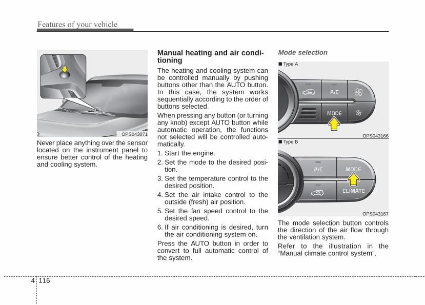
Features of your vehicle
1164
Never place anything over the sensorlocated on the instrument panel toensure better control of the heatingand cooling system.
Manual heating and air condi-tioningThe heating and cooling system canbe controlled manually by pushingbuttons other than the AUTO button.In this case, the system workssequentially according to the order ofbuttons selected.When pressing any button (or turningany knob) except AUTO button whileautomatic operation, the functionsnot selected will be controlled auto-matically.1. Start the engine.2. Set the mode to the desired posi-
tion.3. Set the temperature control to the
desired position.4. Set the air intake control to the
outside (fresh) air position.5. Set the fan speed control to the
desired speed.6. If air conditioning is desired, turn
the air conditioning system on.Press the AUTO button in order toconvert to full automatic control ofthe system.
Mode selection
The mode selection button controlsthe direction of the air flow throughthe ventilation system.Refer to the illustration in the“Manual climate control system”.
OPS043071 OPS043166
OPS043167
■ Type B
■ Type A

4 117
Features of your vehicle
The air flow outlet port is convertedas follows:
Vent mode (B, D)
Air flow is directed toward the upperbody and face. Additionally, each out-let can be controlled to direct the airdischarged from the outlet.
Vent-Floor mode (B, D, C, E)
Air flow is discharged towards theface and floor.
Floor mode (C, E, A, D)
Most of the air flow is directed to thefloor, with a small amount of the airbeing directed to the windshield andside window defroster.
Floor/Defrost mode(A, C, E, D)
Most of the air flow is directed to thefloor and the windshield with a smallamount directed to the side windowdefrosters.
Defrost mode (A, D)
Most of the air flow is directed to thewindshield with a small amount of airdirected to the side window defrosters.
OPS043168
OPS043169
■ Type B
■ Type A

Features of your vehicle
1184
Instrument panel vents
The outlet port can be opened orclosed separately using the thumb-wheel.Also, you can adjust the direction ofair delivered from these vents usingthe vent control lever as shown.
Temperature control
• Type AThe temperature will increase to themaximum (HI) by pushing the button( ).
The temperature will decrease to theminimum (Lo) by pushing the button( ).When pushing the button, the tem-perature will increase or decrease by0.5°C/1°F. When set to the lowesttemperature setting, the air condi-tioning will operate continuously.
• Type BThe temperature will increase to themaximum (HI) by turning the knob tothe right extremely.The temperature will decrease to theminimum (Lo) by turning the knob tothe left extremely.When turning the knob, the tempera-ture will increase or decrease by0.5°C/1°F. When set to the lowesttemperature setting, the air condi-tioning will operate continuously.
OPS043059 OPS043170
OPS043171
■ Type B
■ Type A
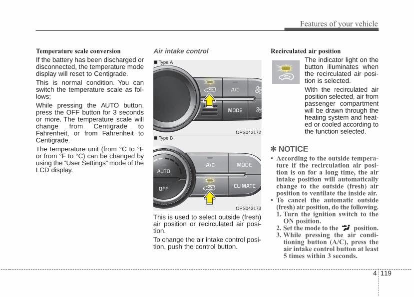
4 119
Features of your vehicle
Temperature scale conversion
If the battery has been discharged ordisconnected, the temperature modedisplay will reset to Centigrade.This is normal condition. You canswitch the temperature scale as fol-lows;While pressing the AUTO button,press the OFF button for 3 secondsor more. The temperature scale willchange from Centigrade toFahrenheit, or from Fahrenheit toCentigrade.The temperature unit (from °C to °For from °F to °C) can be changed byusing the “User Settings” mode of theLCD display.
Air intake control
This is used to select outside (fresh)air position or recirculated air posi-tion.To change the air intake control posi-tion, push the control button.
Recirculated air position
The indicator light on thebutton illuminates whenthe recirculated air posi-tion is selected.With the recirculated airposition selected, air frompassenger compartmentwill be drawn through theheating system and heat-ed or cooled according tothe function selected.
✽✽ NOTICE• According to the outside tempera-
ture if the recirculation air posi-tion is on for a long time, the airintake position will automaticallychange to the outside (fresh) airposition to ventilate the inside air.
• To cancel the automatic outside(fresh) air position, do the following. 1. Turn the ignition switch to the
ON position.2. Set the mode to the position.3. While pressing the air condi-
tioning button (A/C), press theair intake control button at least5 times within 3 seconds.
OPS043172
OPS043173
■ Type B
■ Type A

Features of your vehicle
1204
Outside (fresh) air position
The indicator light on thebutton does not illuminatewhen the outside (fresh)air position is selected.With the outside (fresh)air position selected, airenters the vehicle fromoutside and is heated orcooled according to thefunction selected.
Prolonged operation of the heater inthe recirculated air position (without airconditioning selected) may cause fog-ging of the windshield and side win-dows and the air within the passengercompartment may become stale.In addition, prolonged use of the airconditioning with the recirculated airposition selected will result in exces-sively dry air in the passenger com-partment.
WARNING - Recirculatedair
Continuous use of the climatecontrol system in the recirculat-ed air position can causedrowsiness or sleepiness, andloss of vehicle control. Set theair intake control to the outside(fresh) air position as much aspossible while driving.
WARNING - Reduced visibility
Continued climate control sys-tem operation in the recirculat-ed air position may allowhumidity to increase insidevehicle which may fog the glassand obscure visibility.
120
WARNING - Sleeping withAC on
Do not sleep in a vehicle withthe air conditioning or heatingsystem on as this may causeserious harm or death due to adrop in the oxygen level and/orbody temperature.
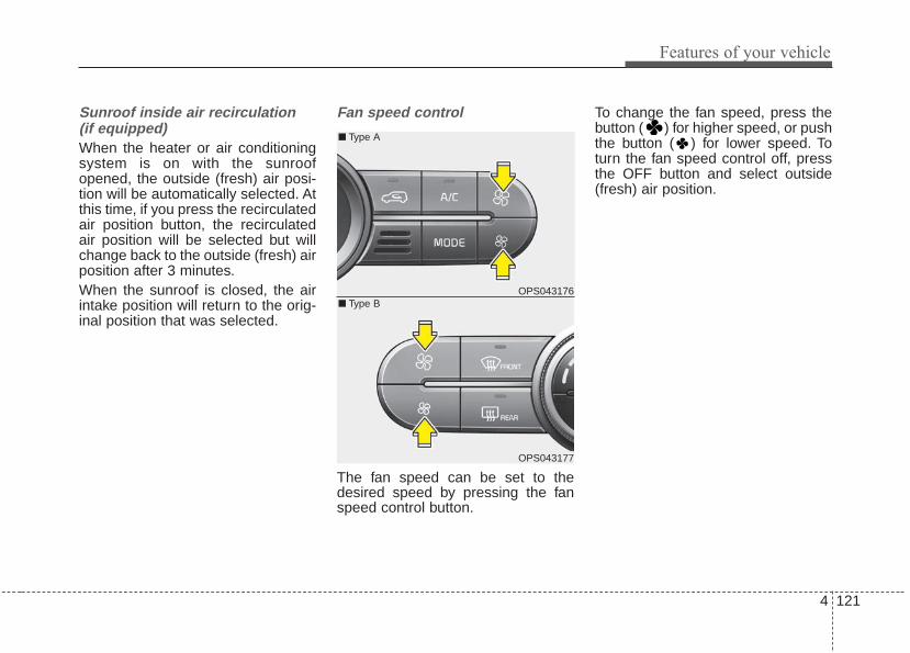
4 121
Features of your vehicle
Sunroof inside air recirculation(if equipped)When the heater or air conditioningsystem is on with the sunroofopened, the outside (fresh) air posi-tion will be automatically selected. Atthis time, if you press the recirculatedair position button, the recirculatedair position will be selected but willchange back to the outside (fresh) airposition after 3 minutes.When the sunroof is closed, the airintake position will return to the orig-inal position that was selected.
Fan speed control
The fan speed can be set to thedesired speed by pressing the fanspeed control button.
To change the fan speed, press thebutton ( ) for higher speed, or pushthe button ( ) for lower speed. Toturn the fan speed control off, pressthe OFF button and select outside(fresh) air position.
OPS043176
OPS043177
■ Type B
■ Type A

Features of your vehicle
1224
Air conditioning
Push the A/C button to turn the airconditioning system on (indicatorlight will illuminate).Push the button again to turn the airconditioning system off.
Blower OFF
Push the OFF button to turn off theblower. However you can still operatethe mode and air intake buttons aslong as the ignition switch is in theposition ON.
Climate information screen selection (if equipped)
Press the climate information screenselection button to view climate infor-mation in full screen mode.
OPS043174
OPS043175
■ Type B
■ Type A
OPS043178
OPS043179
■ Type B
■ Type A
OPS043180
■ Type B

4 123
Features of your vehicle
System operationVentilation1. Set the mode to the position.2. Set the air intake control to the
outside (fresh) air position.3. Set the temperature control to the
desired position.4. Set the fan speed control to the
desired speed.
Heating1. Set the mode to the position.2. Set the air intake control to the
outside (fresh) air position.3. Set the temperature control to the
desired position.4. Set the fan speed control to the
desired speed.5. If dehumidified heating is desired,
turn the air conditioning system (ifequipped) on.
• If the windshield fogs up, set themode to the or position.
Operation Tips
• To keep dust or unpleasant fumesfrom entering the vehicle throughthe ventilation system, temporarilyset the air intake control to therecirculated air position. Be sure toreturn the control to the fresh airposition when the irritation haspassed to keep fresh air in thevehicle. This will help keep the driv-er alert and comfortable.
• Air for the heating/cooling systemis drawn in through the grilles justahead of the windshield. Careshould be taken that these are notblocked by leaves, snow, ice orother obstructions.
• To prevent interior fog on the wind-shield, set the air intake control tothe fresh air position and fan speedto the desired position, turn on theair conditioning system, and adjustthe temperature control to desiredtemperature.
Air conditioning (if equipped) All Kia Air Conditioning Systems arefilled with R-134a refrigerant.1. Start the engine. Press the air con-
ditioning button.2. Set the mode to the position.3. Set the air intake control to the
outside air or recirculated air posi-tion.
4. Adjust the fan speed control andtemperature control to maintainmaximum comfort.
• When maximum cooling is desired,set the temperature control to theextreme left position, set the modecontrol to the MAX A/C position,then set the fan speed control tothe highest speed.

Features of your vehicle
1244
Air conditioning system operation tips
• If the vehicle has been parked indirect sunlight during hot weather,open the windows for a short timeto let the hot air inside the vehicleescape.
• To help reduce moisture inside ofthe windows on rainy or humiddays, decrease the humidity insidethe vehicle by operating the airconditioning system.
• During air conditioning systemoperation, you may occasionallynotice a slight change in enginespeed as the air conditioning com-pressor cycles. This is a normalsystem operation characteristic.
• Use the air conditioning systemevery month only for a few minutesto ensure maximum system per-formance.
• When using the air conditioningsystem, you may notice clear waterdripping (or even puddling) on theground under the passenger sideof the vehicle. This is a normal sys-tem operation characteristic.
• Operating the air conditioning sys-tem in the recirculated air positionprovides maximum cooling, how-ever, continual operation in thismode may cause the air inside thevehicle to become stale.
• During cooling operation, you mayoccasionally notice a misty air flowbecause of rapid cooling andhumid air intake. This is a normalsystem operation characteristic.
CAUTION - Excessive A/C• When using the air condition-
ing system, monitor the tem-perature gauge closely whiledriving up hills or in heavytraffic when outside tempera-tures are high. Air condition-ing system operation maycause engine overheating.Continue to use the blower fanbut turn the air conditioningsystem off if the temperaturegauge indicates engine over-heating.
• When opening the windows inhumid weather air condition-ing may create water dropletsinside the vehicle. Sinceexcessive water droplets maycause damage to electricalequipment, air conditioningshould only be used with thewindows closed.
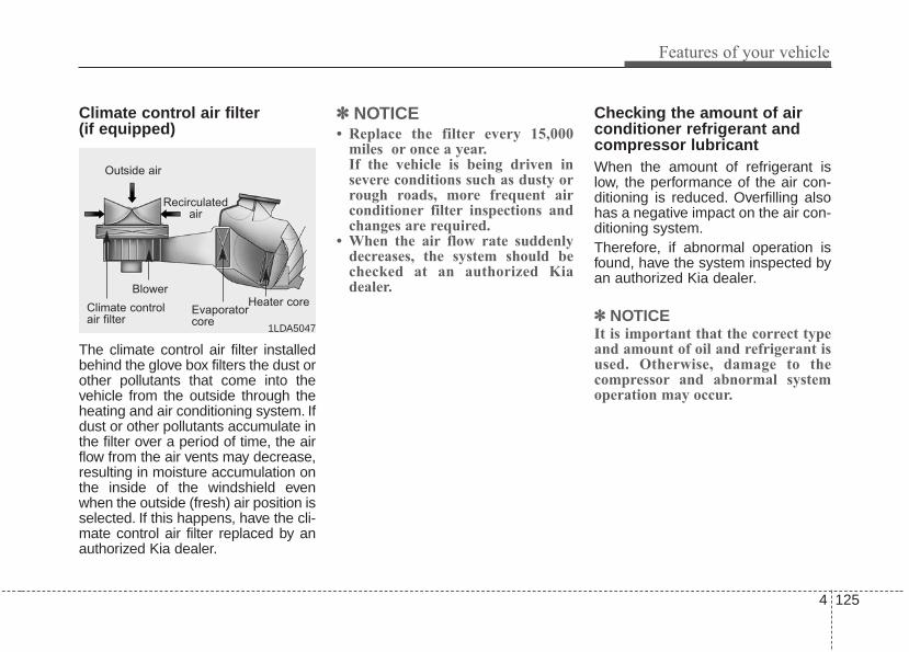
4 125
Features of your vehicle
Climate control air filter (if equipped)
The climate control air filter installedbehind the glove box filters the dust orother pollutants that come into thevehicle from the outside through theheating and air conditioning system. Ifdust or other pollutants accumulate inthe filter over a period of time, the airflow from the air vents may decrease,resulting in moisture accumulation onthe inside of the windshield evenwhen the outside (fresh) air position isselected. If this happens, have the cli-mate control air filter replaced by anauthorized Kia dealer.
✽✽ NOTICE• Replace the filter every 15,000
miles or once a year.If the vehicle is being driven insevere conditions such as dusty orrough roads, more frequent airconditioner filter inspections andchanges are required.
• When the air flow rate suddenlydecreases, the system should bechecked at an authorized Kiadealer.
Checking the amount of airconditioner refrigerant andcompressor lubricantWhen the amount of refrigerant islow, the performance of the air con-ditioning is reduced. Overfilling alsohas a negative impact on the air con-ditioning system.Therefore, if abnormal operation isfound, have the system inspected byan authorized Kia dealer.
✽✽ NOTICEIt is important that the correct typeand amount of oil and refrigerant isused. Otherwise, damage to thecompressor and abnormal systemoperation may occur.
1LDA5047
Outside air
Recirculatedair
Climate controlair filter
Blower
Evaporatorcore
Heater core

Features of your vehicle
1264
WARNINGThe oil and refrigerant in yourvehicle's air conditioning sys-tem is under very high pres-sure. If proper service proce-dures are not followed an explo-sion may result. To reduce therisk of serious injury or death,the air conditioning system inyour vehicle should only beserviced by trained and certi-fied technicians.

4 127
Features of your vehicle
• For maximum defrosting, set thetemperature control to the extremeright/hot position and the fan speedcontrol to the highest speed.
• If warm air to the floor is desiredwhile defrosting or defogging, set themode to the floor-defrost position.
• Before driving, clear all snow andice from the windshield, rear win-dow, outside rear view mirrors, andall side windows.
• Clear all snow and ice from thehood and air inlet in the cowl grilleto improve heater and defrosterefficiency and to reduce the proba-bility of fogging up inside of thewindshield.
Manual climate control systemTo defog inside windshield
1. Select any fan speed except “0”position.
2. Select desired temperature.3. Select the or mode.4. The outside (fresh) air and air con-
ditioning will be selected automat-ically.
If the air conditioning and outside(fresh) air position are not selectedautomatically, press the correspon-ding button manually.
WINDSHIELD DEFROSTING AND DEFOGGING
OPS043181
WARNING - Windshieldheating
Do not use the or posi-tion during cooling operation inextremely humid weather. Thedifference between the temper-ature of the outside air and thatof the windshield could causethe outer surface of the wind-shield to fog up, causing loss ofvisibility. In this case, set themode selection knob or buttonto the position and fanspeed control knob or button tothe lower speed.

Features of your vehicle
1284
To defrost outside windshield
1. Set the fan speed to the highest(extreme right) position.
2. Set the temperature to theextreme hot position.
3. Select the position.4. The outside (fresh) air and air con-
ditioning will be selected automat-ically.
Automatic climate control systemTo defog inside windshield
1. Set the fan speed to the desiredposition.
2. Select desired temperature.
3. Press the defrost button ( ).4. The air-conditioning will be turned
on according to the detected ambi-ent temperature, outside (fresh) airposition and higher fan speed willbe selected automatically.
If the air-conditioning, outside (fresh)air position and higher fan speed arenot selected automatically, adjust thecorresponding button or knob manu-ally.If the position is selected, with alow fan speed, a higher fan speedmay be automatically selected.
OPS043182OPS043183
OPS043185
■ Type B
■ Type A

4 129
Features of your vehicle
To defrost outside windshield
1. Set fan speed to the highest posi-tion.
2. Set temperature to the Maximum(HI).
3. Press the defrost button ( ).
4. The air-conditioning will be turnedon according to the detectedambient temperature and outside(fresh) air position will be selectedautomatically.
If the position is selected, with alow fan speed, a higher fan speedmay be automatically selected.
Defogging logicTo reduce the possibility of foggingup the inside of the windshield, theair intake or air conditioning are con-trolled automatically according tocertain conditions such as or position. To cancel or return to thedefogging logic, do the following.
OPS043184
OPS043186
■ Type B
■ Type A

Features of your vehicle
1304
Manual climate control system
1. Turn the ignition switch to the ONposition.
2. Turn the mode selection knob tothe defrost position ( ).
3. Within 10 seconds after select thedefrost positon, press the airintake control button ( ) at least5 times within 3 seconds.
The indicator on the air intake buttonblinks 3 times with 0.5 seconds ofinterval. It indicates that the defog-ging logic is canceled or returned tothe programmed status.
If the battery has been discharged ordisconnected, it will be reset to thedefog logic status.
Automatic climate control system
1. Turn the ignition switch to the ONposition.
2. Press the defrost button ( ).
OPS043187
OPS043189
OPS043188
■ Type B
■ Type A

4 131
Features of your vehicle
3. While pressing the air conditioningbutton (A/C), press the air intakecontrol button ( ) at least 5times within 3 seconds.
The indicator on the air intake buttonblinks 3 times with 0.5 seconds ofinterval. It indicates that the defog-ging logic is canceled or returned tothe programmed status.
If the battery has been discharged ordisconnected, it will be reset to thedefog logic status. When the ignition switch is in the ON
position, the clean air function turnson automatically.Also, the clean air function turns offautomatically, when the ignitionswitch turns to the OFF position.
OPS043206
CLEAN AIR (IF EQUIPPED)

Features of your vehicle
1324
These compartments can be used tostore small items.• To avoid possible theft, do not
leave valuables in the storagecompartment.
• Always keep the storage compart-ment covers closed while driving.Do not attempt to place so manyitems in the storage compartmentthat the storage compartmentcover cannot close securely.
Center console storage
These compartments can be used tostore small items required by thedriver or front passenger.To open the center console storage,pull up the lever. (Type B)
Glove box
To open the glove box, push the buttonand the glove box will automaticallyopen. Close the glove box after use.Always keep the glove box closedwhile the vehicle is in operation.
STORAGE COMPARTMENT
OPS043062WARNING - Flammablematerials
Do not store, propane cylindersor other flammable/explosivematerials in the vehicle. Theseitems may catch fire and/orexplode if the vehicle is exposedto hot temperatures for extendedperiods.
OPS043060
OPS043061
■ Type B
■ Type A
WARNING - Glove boxTo reduce the risk of injury in anaccident or sudden stop, alwayskeep the glove box door closedwhile driving.

4 133
Features of your vehicle
Cool box (if equipped)
You can keep beverage cans or otheritems cool in the glove box.1. Turn on the air conditioning.2. Slide the open/close lever of the
vent installed in the glove box tothe open position.
3. When the cool box is not used,slide the lever to the closed posi-tion.
If some items in the cool box blockthe vent, the cooling effectiveness ofthe coolbox is reduced.
✽✽ NOTICEDo not put perishable food in thecool box because it may not main-tain the necessary consistent tem-perature to keep the food fresh.
✽✽ NOTICEIf the temperature control knob is inthe warm or hot position, warm orhot air will flow into the glove box.
Sunglass holder
To open the sunglass holder, pressthe cover and the holder will slowlyopen. Place your sunglasses with thelenses facing out.To close the sunglass holder, push itup.Do not place other items in the sun-glass holder.
OPS043064 OPS043065

Features of your vehicle
1344
Luggage box (if equipped)
You can place a first aid kit, a reflec-tor triangle, tools, etc. in the box foreasy access.
OPS043198
WARNING - Sunglassholder
• Do not keep objects exceptsunglasses inside the sun-glass holder. Such objectscan be thrown from the holderin the event of a sudden stopor an accident, possibly injur-ing the passengers in thevehicle.
• Do not open the sunglassholder while the vehicle ismoving. The rear view mirrorof the vehicle can be blockedby an opened sunglass holder.

4 135
Features of your vehicle
Cup holder
Cups or small beverage cans may beplaced in the cup holders.
Rear (if equipped)
To use the cup holder, folding thecenter seat or pull down the armrest.
INTERIOR FEATURES
WARNING - Hot liquidsDo not place uncovered cupswith hot liquid in the cup holderwhile the vehicle is in motion. Ifthe hot liquid spills, you burnyourself. Such a burn to thedriver could lead to loss of con-trol of the vehicle. OPS043067
■ Type A
OPS043066
■ Type B
OPS043068CAUTION• When cleaning spilled liquids,
do not dry the cup holder athigh temperature. This maydamage the cup holder.
• When cleaning spilled liquids,do not dry the cup holder athigh temperature. This maydamage the cup holder.

Features of your vehicle
1364
Sunvisor
Use the sunvisor to shield direct lightthrough the front or side windows.To use the sunvisor, pull it downward.To use the sunvisor for the side window,pull it downward, unsnap it from thebracket (1) and swing it to the side (2).Adjust the sunvisor extension for-ward or backward (3). (if equipped)To use the vanity mirror, pull down thevisor and slide the mirror cover (4).To use the vanity mirror lamp, switchit on. (if equipped)The ticket holder (5, if equipped) isprovided for holding a tollgate ticket.
Seat warmer (if equipped)
The seat warmer is provided to warmthe front seats during cold weather.With the ignition switch in the ONposition, push either of the switchesto warm the driver's seat or the frontpassenger's seat.
OVG049174
CAUTION - Vanity mirror lamp (if equipped)
If you use the vanity mirrorlamp, turn off the lamp beforereturning the sunvisor to itsoriginal position. It could resultin battery discharge and possi-ble sunvisor damage.
OPS033012
■ Type A
OPS033013
■ Type B

4 137
Features of your vehicle
During mild weather or under condi-tions where the operation of the seatwarmer is not needed, keep theswitches in the "OFF" position.• Each time you press the switch,
the temperature setting of the seatwill change as follows :
• The seat warmer defaults to theOFF position whenever the ignitionswitch is turned on.
• When pressing the switch for morethan 1.5 seconds with the seatwarmer operating, the seat warmerwill turn OFF.
✽✽ NOTICEWith the seat warmer switch in theON position, the heating system in theseat turns off or on automaticallydepending on the seat temperature.
✽✽ NOTICEBe careful not to spill liquid such aswater or beverages on the seat. If youspill some liquid, wipe the seat with adry towel. Before using the seatwarmer, dry the seat completely.
CAUTION - Seat damage• When cleaning the seats, do
not use an organic solventsuch as paint thinner, ben-zene, alcohol and gasoline.Doing so may damage the sur-face of the heater or seats.
• To prevent overheating theseat warmer, do not place any-thing on the seats that insu-lates against heat, such asblankets, cushions or seatcovers while the seat warmeris in operation.
• Do not place heavy or sharpobjects on seats equippedwith seat warmers. Damage tothe seat warming componentscould occur.
OFF
HIGH ( )
LOW ( )
→→
→
• Type AOFF
HIGH ( )
MIDDLE ( )*
LOW ( )
→→
→
→
• Type B
WARNING - Seat heaterburns
The seat warmer may causeburns, even at low tempera-tures, if used over a long periodof time. Never allow passengerswho may not be able to takecare of themselves to beexposed to the risk of seatheater burns. These include:1. Infants, children, elderly or
disabled persons, or hospitaloutpatients
2. Persons with sensitive skinor those that burn easily
3. Fatigued individuals4. Intoxicated individuals5. Individuals taking medication
that can cause drowsiness orsleepiness (sleeping pills,cold tablets, etc.)

Features of your vehicle
1384
Seat air ventilation (if equipped)
The temperature setting of the seatchanges according to the switchposition.• If you want to cool your seat cush-
ion, press the switch (blue color).• Each time you press the button,
the airflow will change as follows:
• When pressing the switch for morethan 1.5 seconds with the seat airventilation operating, the seat airventilation will turn OFF.
• The seat air ventilation defaults tothe OFF position whenever theignition switch is turned on.
✽✽ NOTICEBe careful not to spill liquid such aswater or beverages on the seat. Ifyou spill some liquid, wipe the seatwith a dry towel. Before using theair ventilation seat, dry the seatcompletely.
Rear seat warmer (if equipped)
The seat warmer is provided to warmthe rear outboard seats during coldweather. With the ignition switch inthe ON position, push either of theswitches to warm rear seats.During mild weather or under condi-tions where the operation of the seatwarmer is not needed, keep theswitches in the "OFF" position.
OPS033014
OFF
HIGH ( )
MIDDLE ( )
LOW ( )
→→
→
→
CAUTION - Seat damage• When cleaning the seats, do
not use an organic solventsuch as paint thinner, ben-zene, alcohol and gasoline.Doing so may damage the airventilation seat.
• Do not place heavy or sharpobjects on the seat. Thosethings may damage the airventilation seat.
OPS033031
→
OFF → HIGH ( ) → LOW ( )
4 139
Features of your vehicle
• When pressing the switch for morethan 1.5 seconds with the seatwarmer operating, the seat warmerwill turn OFF.
• The seat warmer defaults to theOFF position whenever the enginestart/stop button (the ignition switch)is turned on.
✽✽ NOTICEWith the seat warmer switch in theON position, the heating system inthe seat turns off or on automaticallydepending on the seat temperature.
✽✽ NOTICEBe careful not to spill liquid such aswater or beverages on the seat. If youspill some liquid, wipe the seat with adry towel. Before using the seatwarmer, dry the seat completely.
CAUTION - Seat damage
• When cleaning the seats, donot use an organic solventsuch as thinner, benzene, alco-hol and gasoline. Doing so maydamage the surface of theheater or seats.
• To prevent overheating the seatwarmer, do not place anythingon the seats that insulatesagainst heat, such as blankets,cushions or seat covers whilethe seat warmer is in operation.
• Do not place heavy or sharpobjects on seats equippedwith seat warmers. Damage tothe seat warming componentscould occur.
WARNING - Seat heaterburns
The seat warmer may causeburns, even at low tempera-tures, if used over a long periodof time. Never allow passengerswho may not be able to takecare of themselves to beexposed to the risk of seatheater burns. These include:1. Infants, children, elderly or
disabled persons, or hospitaloutpatients
2. Persons with sensitive skinor those that burn easily
3. Fatigued individuals4. Intoxicated individuals5. Individuals taking medication
that can cause drowsiness orsleepiness (sleeping pills,cold tablets, etc.)

Features of your vehicle
1404
Power outlet (if equipped)
The power outlet is designed to pro-vide power for mobile telephones orother devices designed to operatewith vehicle electrical systems. Thedevices should draw less than 10amps with the engine running.
• Use the power outlet only when theengine is running and remove theaccessory plug after use. Using theaccessory plug for prolonged peri-ods of time with the engine off couldcause the battery to discharge.
• Only use 12V electric accessorieswhich are less than 10A(Driver’sside) or 15A(Passenger’s side) inelectric capacity.
• Adjust the air-conditioner or heaterto the lowest operating level whenusing the power outlet.
• Close the cover when not in use.• Some electronic devices can cause
electronic interference whenplugged into a vehicle’s power out-let. These devices may causeexcessive audio static and malfunc-tions in other electronic systems ordevices used in your vehicle.
OPS043069
OPS043070
■ Rear (if equipped)
■ Front (Type A)WARNING - Electric
shockDo not put a finger or a foreignelement (pin, etc.) into a poweroutlet and do not touch with awet hand.You may get an electricshock.

4 141
Features of your vehicle
Clothes hanger (if equipped)
To use the hanger, pull down theupper portion of hanger.Be careful when opening and closingthe doors. Clothes, etc. may getcaught between the door gap.
Floor mat anchor(s)
When using a floor mat on the floorcarpet, make sure it attaches to thefloor mat anchor(s) in your vehicle.This keeps the floor mat from slidingforward.
The following must be observedwhen installing ANY floormat to thevehicle.• Ensure that the floormats are
securely attached to the vehicle'sfloormat anchor(s) before drivingthe vehicle.
• Do not use ANY floormat that can-not be firmly attached to the vehi-cle's floormat anchors.
• Do not stack floormats on top ofone another (e.g. all-weather rub-ber mat on top of a carpeted floor-mat). Only a single floormat shouldbe installed in each position.
IMPORTANT - Your vehicle wasmanufactured with driver's side floor-mat anchors that are designed tosecurely hold the floormat in place.To avoid any interference with pedaloperation, Kia recommends that onlythe Kia floormat designed for use inyour vehicle be installed.
OTFNCO2001
■ Driver's side ■ Passenger's side
WARNING - After marketfloor mat
Do not install aftermarket floormats that are not capable ofbeing securely attached to thevehicle's floor mat anchors.Unsecured floor mats can inter-fere with pedal operation.
CAUTION - Hangingclothing
Do not hang heavy clothes,since those may damage thehook.
ORP042186

Features of your vehicle
1424
Luggage net holder (if equipped)
To keep items from shifting in thecargo area, you can use the holderslocated in the cargo area to attachthe luggage net.If necessary, contact your authorizedKia dealer to obtain a luggage net.
Cargo area cover (if equipped)
Use the cargo area cover to hideitems stored in the cargo area.
OPS043193
WARNING - Luggage net• Always keep your face and
body out of the luggage netrecoil path and avoid usingthe luggage net when thestraps have visible signs ofwear or damage. The luggagenet can snap and causeinjuries.
• All cargo should be evenlydistributed, properly securedand never piled higher thanthe seatback.
CAUTIONTo prevent damage to the vehi-cle, care should be taken whencarrying fragile or bulky objectsin the luggage compartment.
OPS043199L
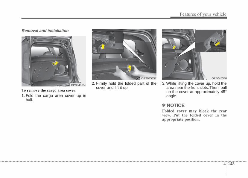
4 143
Features of your vehicle
Removal and installation
To remove the cargo area cover:
1. Fold the cargo area cover up inhalf.
2. Firmly hold the folded part of thecover and lift it up.
3. While lifting the cover up, hold thearea near the front slots.Then, pullup the cover at approximately 45°angle.
✽✽ NOTICE Folded cover may block the rearview. Put the folded cover in theappropriate position.
OPS045355
OPS045357 OPS045356

Features of your vehicle
1444
To install the cargo area cover:
To use the cargo area cover, insertthe 4 edges into the slots.
OPS043200L
WARNING - Objects• Do not place objects on the
cargo area cover. Suchobjects may be thrown aboutinside the vehicle and possi-bly injure vehicle occupantsduring an accident or whenbraking.
• All cargo should be evenlydistributed, properly securedand never piled higher thanthe seatback.
CAUTION - LuggageSince the cargo area cover maybe damaged or malformed, donot put luggage on it when it isused.

4 145
Features of your vehicle
Mounting bracket for roof carrier(if equipped)
To install or remove a roof carrier,you can use the mounting bracketand cover on the roof.When you install a roof carrier, dothe following procedure.
1. Insert a slim tool (coin or flat bladedriver) into the slot and slide thecover toward the arrow on thecover.
2. Rotate the cover half way andinsert the cover on the roof hole asthe illustration.
✽✽ NOTICE To prevent losing the roof carriercover, install the cover on the roofbefore you install the roof carrier.
3. After using the roof carrier, installthe cover back on the roof in thereverse order.
✽✽ NOTICE If the vehicle is equipped with a sun-roof, be sure not to position cargoonto the roof in such a way that itcould interfere with sunroof opera-tion.
EXTERIOR FEATURES
OED046091
OPS043207
CAUTION - Loading roofrack
When carrying cargo on the roofrack, take the necessary precau-tions to make sure the cargodoes not damage the roof of thevehicle.
• When carrying large objects on theroof, make sure they do not exceedthe overall roof length or width.
• The vehicle center of gravity will behigher when items are loaded ontothe roof. Avoid sudden starts, brak-ing, sharp turns, abrupt maneuversor high speeds that may result inloss of vehicle control or rolloverresulting in an accident.
• To prevent damage or loss of cargowhile driving, check frequentlybefore or while driving to makesure the items on the roof aresecurely fastened.
WARNING - Driving withroof load
Always drive slow and turn cor-ners carefully when carryingitems on the roof rack.The vehi-cle center of gravity will behigher when items are loadedonto the roof rack.
4 146
Features of your vehicle

4 147
Features of your vehicle
If you install aftermarket HID headlamps, your vehicle’s audio and elec-tronic devices may malfunction.
Antenna (if equipped)
Your vehicle uses a roof antenna toreceive AM or/and FM broadcast sig-nals.This antenna pole is removable. Toremove the roof antenna pole, turn itcounterclockwise. To install the roofantenna pole, turn it clockwise.
• When reinstalling your roof anten-na, it is important that it is fullytightened and adjusted to theupright position to ensure properreception.
• When cargo is loaded on the roofrack, do not place the cargo nearthe antenna pole to ensure properreception.
OHM048154N
AUDIO SYSTEM
CAUTION - AntennaBefore entering a place with alow height clearance or a carwash, remove the antenna poleby rotating it counterclockwise.If not, the antenna may be dam-aged.

Features of your vehicle
1484
Audio remote control (if equipped)
The steering wheel audio remotecontrol button may be installed.Do not operate the audio remotecontrol buttons simultaneously.
VOLUME (VOL+/ VOL-) (1)• Push the VOL + to increase volume.• Push the VOL - to decrease volume.
SEEK/PRESET ( / ) (2)If the SEEK/PRESET button ispressed for more than 1 second, itwill work as follows in each mode.
RADIO mode
It will function as the AUTO SEEKselect button.
USB mode
It will function as the FF/REW button.
If the SEEK/PRESET button ispressed for less than 1 second, it willwork as follows in each mode.
OPS043190
WARNINGDriving while distracted canresult in a loss of vehicle con-trol that may lead to an acci-dent, severe personal injury anddeath. The driver’s primaryresponsibility is in the safe andlegal operation of a vehicle, anduse of any handheld devices,other equipment or vehicle sys-tems which take the driver’seyes, attention and focus awayfrom the safe operation of avehicle or that are not permissi-ble by law should never be usedduring operation of the vehicle.

4 149
Features of your vehicle
RADIO mode
It will function as the PRESET STA-TION select buttons.
USB mode
It will function as the FILE UP/DOWNbutton.
MODE (3)Press the button to select Radio,USB or AUX.
Detailed information for audio controlbuttons is described in the followingpages in this section.
Aux and USB port (if equipped)
If your vehicle has an aux and/orUSB(universal serial bus) port, youcan use an aux port to connect audiodevices and an USB port to plug inan USB.
When using a portable audio deviceconnected to the power outlet, noisemay occur during playback. If thishappens, use the power source ofthe portable audio device.
OPS043194

Features of your vehicle
1504
Speaker lights (if equipped)
The speaker lights that lights aroundthe front speaker is adjusted by turn-ing the knob as follows.
1. OFF : The light turns off.2. MUSIC :
The red light blinks according to thesound of the audio.If the audio is not turned on, thelight does not turn on.
3. MOOD :The light color changes automati-cally at regular interval.
4. +/- :When the lights are on, push theillumination button to adjust thelight intensity.If low lighting grade is selected, theintensity of light may be weak ormay not illuminate according to theaudio volume or selected condition.
The lighting around the front speakermay not illuminate when the sound ofthe audio is low.
Do not use the lights for extendedperiods when engine is not running.It may cause battery discharge.
✽✽ NOTICEWhen the doors are opened, thelighting system will not operate.
OPS043195
OPS043196

4 151
Features of your vehicle
How vehicle audio works
AM and FM radio signals are broadcastfrom transmitter towers located aroundyour city. They are intercepted by theradio antenna on your vehicle.This sig-nal is then processed by the radio andsent to your vehicle speakers.However, in some cases the signalcoming to your vehicle may not bestrong and clear.This can be due to factors, such asthe distance from the radio station,closeness of other strong radio sta-tions or the presence of buildings,bridges or other large obstructions inthe area.
AM broadcasts can be received atgreater distances than FM broad-casts. This is because AM radiowaves are transmitted at low fre-quencies. These long distance,lowfrequency radio waves can follow thecurvature of the earth rather thantravelling straight. In addition, theycurve around obstructions resultingin better signal coverage.
FM broadcasts are transmitted athigh frequencies and do not bend tofollow the earth's surface. Becauseof this, FM broadcasts generallybegin to fade within short distancesfrom the station. Also, FM signals areeasily affected by buildings, moun-tains, and obstructions. This can leadto undesirable or unpleasant listen-ing conditions which might lead youto believe a problem exists with yourradio. The following conditions arenormal and do not indicate radiotrouble:
JBM002
AM reception
JBM001
FM reception
JBM003
FM radio station

Features of your vehicle
1524
• Fading - As your vehicle movesaway from the radio station, thesignal will weaken and sound willbegin to fade. When this occurs,we suggest that you select anotherstronger station.
• Flutter/Static - Weak FM signals orlarge obstructions between thetransmitter and your radio can dis-turb the signal causing static orfluttering noises to occur. Reducingthe treble level may lessen thiseffect until the disturbance clears.
• Station Swapping - As an FM sig-nal weakens, another more power-ful signal near the same frequencymay begin to play. This is becauseyour radio is designed to lock ontothe clearest signal. If this occurs,select another station with astronger signal.
• Multi-Path Cancellation - Radiosignals being received from sever-al directions can cause distortionor fluttering. This can be caused bya direct and reflected signal fromthe same station, or by signalsfrom two stations with close fre-quencies. If this occurs, selectanother station until the conditionhas passed.
Using a cellular phone or a two-way radioWhen a cellular phone is used insidethe vehicle, noise may be producedfrom the audio system. This does notmean that something is wrong withthe audio equipment. In such a case,try to operate mobile devices as farfrom the audio equipment as possi-ble.
When using a communication sys-tem such as a cellular phone or aradio set inside the vehicle, a sepa-rate external antenna must be fitted.When a cellular phone or a radio setis used with an internal antennaalone, it may interfere with the vehi-cle's electrical system and adverselyaffect safe operation of the vehicle.
JBM005JBM004

4 153
Features of your vehicle
• Adjust the volume to levels thatallow the driver to hear sounds fromoutside of the vehicle. Driving in astate where external sounds cannotbe heard may lead to accidents.
• Pay attention to the volume settingwhen turning the device on. A sud-den output of extreme volumeupon turning the device on couldlead to hearing impairment. (Adjustthe volume to a suitable levelsbefore turning off the device.)
• Turn on the car ignition beforeusing the audio system Do notoperate the audio system for longperiods of time with the ignitionturned off as such operations maylead to battery discharge.
• In case of product malfunction,please contact your place of pur-chase or After Service center.
• Placing the audio system within anelectromagnetic environment mayresult in noise interference.
WARNING - Cell phoneuse
Do not use a cellular phonewhile driving. Stop at a safelocation to use a cellular phone.
WARNING - DriverDistraction
• Do not stare at the screenwhile driving. Staring at thescreen for prolonged periodsof time could lead to trafficaccidents.
• Using the phone while drivingmay lead to a lack of attentionof traffic conditions andincrease the likelihood ofaccidents. Use the phone fea-ture after parking the vehicle.
WARNING - Audio SystemDo not disassemble, assemble,or modify the audio system.Such acts could result in fire orelectric shock.
WARNING - AntennaDo not touch the antenna dur-ing thunder or lightening assuch acts may lead to lightninginduced electric shock.
CAUTIONRefrain from use if the screen isblank or no sound can be hearas these signs may indicateproduct malfunction.

Features of your vehicle
1544
USING THE USB DEVICE• To use an external USB device,
make sure the device is not con-nected when starting up thevehicle. Connect the device afterstarting up.
• If you start the engine when theUSB device is connected, it maydamage the USB device. (USBflashdrives are very sensitive toelectric shock.)
• If the engine is started up orturned off while the external USBdevice is connected, the externalUSB device may not work.
• The System may not play unau-thenticated MP3 or WMA files.1) It can only play MP3 files with
the compression ratebetween 8Kbps ~ 320Kbps.
2) It can only play WMA musicfiles with the compressionrate between 8Kbps ~320Kbps.
• Take precautions for static elec-tricity when connecting or discon-necting the external USB device.
(Continued)
(Continued)• An encrypted MP3 PLAYER is
not recognizable.• Depending on the condition of
the external USB device, theconnected external USB devicecan be unrecognizable.
• When the formatted byte/sectorsetting of External USB device isnot either 512BYTE or2048BYTE, then the device willnot be recognized.
• Use only a USB device format-ted to FAT 12/16/32.
• USB devices without USB I/Fauthentication may not be recog-nizable.
• Make sure the USB connectionterminal does not come in con-tact with the human body orother objects.
• If you repeatedly connect or dis-connect the USB device in ashort period of time, it may breakthe device.
(Continued)
CAUTION - LCD MonitorDo not subject the device tosevere shock or impact. Directpressure onto the front side ofthe monitor may cause damageto the LCD or touch screen.
CAUTION• When cleaning the device,
make sure to turn off theaudio system and use a dryand smooth cloth.
• Never use tough materials,chemical cloths, or solvents(alcohol, benzene, thinners,etc.) as such materials maydamage the device panel orcause color/quality deteriora-tion.
• Prevent caustic solutions suchas perfume and cosmetic oilfrom contacting the dashboardbecause they may cause dam-age or discoloration.

4 155
Features of your vehicle
(Continued)• You may hear a strange noise
when connecting or disconnect-ing a USB device.
• If you disconnect the externalUSB device during playback inUSB mode, the external USBdevice can be damaged or maymalfunction. Therefore, discon-nect the external USB devicewhen the audio is turned off or inanother mode. (e.g, Radio)
• Depending on the type andcapacity of the external USBdevice or the type of the filesstored in the device, there is adifference in the time for recogni-tion the device.
• Do not use the USB device forpurposes other than playingmusic files.
• Playing videos through the USBis not supported.
• Use of USB accessories such asrechargers or heaters using USBI/F may lower performance orcause trouble.
(Continued)
(Continued)• Some USB flash memory read-
ers (such as CF, SD, micro SD,etc.) or external-HDD typedevices can be unrecognizable.
• Music files protected by DRM(DIGITAL RIGHTS MANAGE-MENT) are not recognizable.
• The data in the USB memorymay be lost while using thisaudio. Always back up importantdata on a personal storagedevice.
• Please avoid usingUSB memory prod-ucts which can beused as key chains orcellular phone acces-sories as they could cause dam-age to the USB jack. Pleasemake certain only to use plugtype connector products.
(Continued)• If you use devices such as a
USB hub purchased separately,the vehicle’s audio system maynot recognize the USB device. Inthat case, connect the USBdevice directly to the multimediaterminal of the vehicle.
• If the USB device is divided bylogical drives, only the musicfiles on the highest-priority driveare recognized by car audio.
• Devices such as MP3 Player/Cellular phone/Digital cameracan be unrecognizable by stan-dard USB I/F can be unrecogniz-able.
• Charging through the USB maynot be supported in some mobiledevices.
• USB HDD or USB types liable toconnection failures due to vehi-cle vibrations are not supported.(i-stick type)
• Some non-standard USBdevices (METAL COVER TYPEUSB) can be unrecognizable.
(Continued)

Features of your vehicle
1564
(Continued)• Some iPod® devices, such as the
iPhone®, can be connectedthrough the Bluetooth® WirelessTechnology interface. The devicemust have audio Bluetooth®
Wireless Technology capability(such as for stereo headphoneBluetooth® Wireless Technology ).The device can play, but it will notbe controlled by the audio system.
• To use iPod® features within theaudio, use the cable provided uponpurchasing an iPod® device.
• Skipping or improper operationmay occur depending on the char-acteristics of your iPod®/iPhone®
device.• If your iPhone® is connected to
both the Bluetooth® WirelessTechnology and USB, only supportiPod® mode because the soundmay not be properly played inBluetooth® Audio Streaming. Touse Bluetooth® Audio Streaming,disconnect iPod® cable withiPhone®.
(Continued)
(Continued)• When connecting iPod® with the
iPod® Power Cable, insert the con-nector to the multimedia socketcompletely. If not inserted com-pletely, communications betweeniPod® and audio may be interrupt-ed.
• When adjusting the sound effectsof the iPod® and the audio system,the sound effects of both deviceswill overlap and might reduce ordistort the quality of the sound.
• Deactivate (turn off) the equalizerfunction of an iPod® when adjust-ing the audio system’s volume, andturn off the equalizer of the audiosystem when using the equalizer ofan iPod®.
• When not using iPod® with caraudio, detach the iPod® cable fromiPod®. Otherwise, iPod® mayremain in accessory mode, andmay not work properly.
• Beside support 1M cable whenpurchasing iPod/iPhone products,Long Cable cannot be recognized.
USING iPod® DEVICEiPhone® is a registered grademark ofApple inc.• Some iPod® models may not sup-
port communication protocol andfiles may not properly play.Supported iPod® models:- iPhone® 3GS/4- iPod® touch 1st~4th generation- iPod® nano 1st~6th generation- iPod® classic
• The order of search or playback ofsongs in the iPod® can be differentfrom the order searched in theaudio system.
• If the iPod® is disabled due to itsown malfunction, reset the iPod®.(Reset: Refer to iPod® manual)
• An iPod® may not operate normallyon low battery.
(Continued)

4 157
Features of your vehicle
Bluetooth® WirelessTechnology(if equipped)
Bluetooth® Wireless TechnologyThe Bluetooth® word mark and logosare registered trademarks owned byBluetooth SIG, lnc. and any use ofsuch marks by Kia is under license.A Bluetooth® enabled call phone isrequired to use Bluetooth® wirelesstechnology.
Before Using the Bluetooth®
Wireless TechnologyHandsfree
What is Bluetooth® ?• Bluetooth® refers to a short-distance
wireless networking technologywhich uses a 2.4GHz ~ 2.48GHzfrequency to connect variousdevices within a certain distance.
• Supported within PCs, externaldevices, Bluetooth® phones, PDAs,various electronic devices, andautomotive environments,Bluetooth® allows data to be trans-mitted at high speeds without hav-ing to use a connector cable.
• Bluetooth® Handsfree refers to adevice which allows the user toconveniently make phone calls withBluetooth® mobile phones throughthe audio system.
• Bluetooth® Handsfree may not be supported in some mobilephones. To learn more aboutmobile device compatibility, visithttp://www.kia.com/us/en/content/owners/bluetooth.
WARNINGDriving while distracted canresult in a loss of vehicle controlthat may lead to an accident,severe personal injury, anddeath. The driver’s primaryresponsibility is in the safe andlegal operation of a vehicle, anduse of any handheld devices,other equipment, or vehicle sys-tems which take the driver’seyes, attention and focus awayfrom the safe operation of a vehi-cle or which are not permissibleby law should never be used dur-ing operation of the vehicle.

Features of your vehicle
1584
Precautions for Safe Driving
• Bluetooth® Handsfree is a featurethat enables drivers to practicesafe driving. Connecting the headunit with a Bluetooth® phone allowsthe user to conveniently make andreceive calls and use contacts.Before using Bluetooth®, carefullyread the contents of this user’smanual.
• Excessive use or operations whiledriving may lead to negligent driv-ing practices and result in acci-dents. Refrain from excessiveoperations while driving.
• Viewing the screen for prolongedperiods of time is dangerous andmay lead to accidents. When driv-ing, view the screen only for shortperiods of time.
When connecting a Bluetooth®
Phone
• Before connecting the head unitwith the mobile phone, check tosee that the mobile phone sup-ports Bluetooth® features.
• Even if the phone supportsBluetooth®, the phone will not befound during device searches if thephone has been set to hidden stateor the Bluetooth® power is turnedoff. Disable the hidden state or turnon the Bluetooth® power prior tosearching/connecting with theHead unit.
• If you do not want automatic con-nection with your Bluetooth®
device, turn off the Bluetooth® fea-ture within your mobile phone.
• The Handsfree call volume andquality may differ depending on themobile phone.
• Park the vehicle when connectingthe head unit with the mobilephone.
• Bluetooth® connection maybecome intermittently disconnect-ed in some mobile phones. Followthese steps to try again.1.Within the mobile phone, turn
the Bluetooth® function off/onand try again.
2.Turn the mobile phone powerOff/On and try again.
3.Completely remove the mobilephone battery, reboot, and thenagain.
4.Reboot the audio system and tryagain.
5.Delete all paired devices, pairand try again.

4 159
Features of your vehicle
Voice Recognition
• When using the voice recognitionfeature, only commands listedwithin the user's manual are sup-ported.
• Be aware that during the operationof the voice recognition system,pressing any key other than the
key terminate voice recogni-tion mode.
• For superior voice recognition per-formance, position the microphoneused for voice recognition abovethe head of the driver’s seat andmaintain a proper position whensaying commands.
• Within the following situations,voice recognition may not functionproperly due to external sound.- When the windows and sunroof
are open- When the blower AC/heater is
set to high- When entering and passing
through tunnels(Continued)
(Continued)- When driving on rugged and
uneven roads- During severe rain (heavy rains,
windstorms)• Phone related voice commands
can be used only when aBluetooth® Wireless Technologydevice is connected.
• When making calls by stating aname, the corresponding contactmust be downloaded and storedwithin the audio system.
• After downloading the Bluetooth®
Wireless Technology phone book,it takes some times to convert thephone book data into voice infor-mation. During this time, voicerecognition may not properly oper-ate.
• Pronounce the voice commandsnaturally and clearly as if in a nor-mal conversation.

Features of your vehicle
1604
The Bluetooth and Voice Recognition Manual is provided in two versions due to software version differences.Before reading the manual, check the following.
Press the key in FM Radio screen.1. If you can find “FM <89.1>”on the screen,
(Go to 4-161 page)
2. If you can find “FM <87.5~107.9>”on the screen,(Go to 4-206 page)

4 161
Features of your vehicle
■■ AUDIO : AM1A0B2AN, AM1A0B2KN
PS34001N

Features of your vehicle
1624
SYSTEM CONTROLLERSAND FUNCTIONS
❈ Display and settings may differdepending on the selected audio.
Audio Head Unit
(1) Changes to FM/AM/SiriusXM mode.Each time the key is pressed, themode is changed in order of FM1 ➟
FM2 ➟ AM ➟ SAT1 ➟ SAT2 ➟ SAT3.
❈ In Setup>Display, the radio pop upscreen will be displayed when[Mode Pop up] is turned .When the pop up screen is dis-played, use the TUNE knob orkeys ~ to select thedesired mode.
(2) Changes to USB(iPod®), AUX, MyMusic, BT Audio mode.Each time the key is pressed, themode is changed in order ofUSB(iPod®), AUX, My Music, BTAudio.❈ In Setup>Display, the media pop
up screen will be displayed when[Mode Pop up] is turned .When the pop up screen is dis-played, use the TUNE knob orkeys ~ to select thedesired mode.
(3) Operates Phone Screen❈ When a phone is not connected,
the connection screen is dis-played.
(4) Briefly press the key (under 0.8 sec-onds) : Moves to the Display, Sound,Clock, Phone, System setting modesPress and hold the key (over 0.8 sec-onds) : Move to the Time setting screen
(5) Radio Mode : Automatically search-es for broadcast frequencies.USB, iPod®, My Music modes- Briefly press the key (under 0.8
seconds): Moves to next or previ-ous song (file)
- Press and hold the key (over 0.8seconds): Rewinds or fast-forwardsthe current song.
BT Audio mode : Moves to next orprevious song(file)❈ The Play/Pause feature may oper-
ate differently depending on themobile phone.
SEEKTRACK
SETUPCLOCK
PHONE
51
On
MEDIA
61
On
RADIO
PS34001N

4 163
Features of your vehicle
(6) PWR/VOL knobPower : Turns power On/Off by
pressing the knobVolume : Sets volume by turning
the knob left/right
(7) ~ (Preset)Radio mode: Saves frequencies(channels) or receives saved fre-quencies (channels)USB, iPod®, My Music mode- : Repeat- : RandomIn the Radio, Media, Setup, andMenu pop up screen, the numbermenu is selected.
(8) Each time the button is pressed, itsets the screen Off ➟ Screen On ➟
Screen Off❈ Audio operation is maintained and
only the screen will be turned Off.In the screen Off state, press anykey to turn the screen On again.
(9) Radio mode- Shortly press the key : Previews
each broadcast for 5 secondseach.
- Press and hold the key (over 0.8seconds): Previews the broadcastssaved in Preset ~ for 5seconds each.
❈ Press the key again tocontinue listening to the currentfrequency.
❈ SAT Radio does not support thePreset scan feature.
USB, My Music mode- Briefly press the key (under 0.8
seconds): Previews each song(file) for 10 seconds each.
❈ Press the key again tocontinue listening to the currentsong (file).
(10) Displays menus for the current mode.❈ iPod List : Move to parent category
MENU
SCAN
SCAN
61
SCAN
DISP2 RDM
1 RPT
61
PS34001N

Features of your vehicle
1644
(11) Go to previous depth(no previousscreen)
(12) Radio mode- SiriusXM RADIO : Category Search- USB mode : Folder Search
(13) TUNE knobAM/FM mode :- Changes frequency by turning the
knob left/right.SiriusXM Radio Mode:- Changes the station by turning the
knob left/right. Press knob toselect station.
USB, iPod®, My Music mode:- Searches songs (files) by turning
the knob left/right.❈ When the desired song is displayed,
press the knob to play the song.Moves focus in all selection menusand selects menus.
CATFOLDER
BACK

4 165
Features of your vehicle
SETUP
Display Settings
Press the key Select [Display]through TUNE knob or keySelect menu through TUNE knob
Mode Pop up[Mode Pop up] Changes /selection mode• During On state, press the
or key to display the modechange pop up screen.
Media DisplayWhen playing an MP3 file, select thedesired display info from ‘Folder/File’or ‘Album/Artist/Song’.
MEDIARADIO
OffOn
1
SETUPCLOCK

Features of your vehicle
1664
SOUND SETTINGS
Press the key Select [Sound]through TUNE knob or keySelect menu through TUNE knob
ToneThis menu allows you to set theBass, Middle, Treble.
Select [Tone] Select menu throughTUNE knob Turn TUNE knob
left/right to set
• Bass, Middle, Treble : Selects thesound tone.
• Default : Restores default settings.❈ Return : While adjusting values,
pressing the TUNE knob willrestore the parent menu.
PositionThis menu allows you to set theFader, Balance.
Select [Position] Select menuthrough TUNE knob Turn
TUNE knob left/right to set
• Fader, Balance : Selects the soundfader and balance.
• Default : Restores default settings.❈ Return : While adjusting values,
pressing the TUNE knob willrestore the parent menu.
Speed Dependent Volume ControlThis feature will gradually increasethe volume as speed increases tooffset outside noise.Select [Speed Dependent Vol.] Set[On/Off] of TUNE knob
Voice Recognition VolumeAdjusts voice recognition volume.Select [Voice Recognition Vol.] Setvolume of TUNE knob
2
SETUPCLOCK

4 167
Features of your vehicle
CLOCK SETTINGS
Press the key Select [Clock]through TUNE knob or keySelect menu through TUNE knob
Sound SettingsThis menu is used to set the time.Select [Clock Settings] Set through
TUNE knob Press TUNE knob
❈ Adjust the number currently infocus to set the [hour] and pressthe tune knob to set the [minute]and [AM/PM].
Calendar SettingsThis menu is used to set the date.Select [Calendar Settings] Set through
TUNE knob Press TUNE knob
❈ Adjust the number currently infocus to make the settings andpress the tune knob to move to thenext setting.
Time FormatThis function is used to set the12/24 hour time format of theaudio system. Select [TimeFormat] Set 12Hr / 24Hr through
TUNE knob
Clock Display when Power is OFFSelect [Clock Disp.(Pwr Off)] Set
/ through TUNE knob
: Displays time/date on screen: Turn off.Off
On
OffOn
3
SETUPCLOCK
WARNING - Clock SettingDistraction
Do not adjust the clock whiledriving. You may lose yoursteering control and causesevere personal injury or acci-dents.

Features of your vehicle
1684
SYSTEM SETTINGS
Press the key Select[System] Select menu through
TUNE knob
Memory InformationDisplays currently used memory andtotal system memory.Select [Memory Information] OKThe currently used memory is dis-played on the left side while the totalsystem memory is displayed on theright side.
Prompt FeedbackThis feature is used to change voicecommand feedback between Normaland Expert modes.Select [Prompt Feedback] Setthrough TUNE knob• On : This mode is for beginner
users and provides detailedinstructions during voice commandoperation.
• Off : This mode is for expert usersand omits some information duringvoice command operation. (Whenusing Expert mode, guidanceinstructions can be heard throughthe [Help] or [Menu] commands.
LanguageThis menu is used to set the displayand voice recognition language.Select [Language] Set through TUNE knob
❈ The system will reboot after thelanguage is changed.
❈ Language support by region- English, Francais, Espanol
SETUPCLOCK

4 169
Features of your vehicle
RADIO : FM, AM or SiriusXM
SEEKPress the key• Briefly pressing the key (under 0.8
seconds): Automatically searchesfor the next station.
• Pressing and holding the key (over0.8 seconds): While holding the key,frequency changes without stop-ping. When the key is released,automatically searches for the nextfrequency from that point.
Preset SEEKPress the ~ key• Briefly pressing the key (under 0.8
seconds): Plays the frequencysaved in the corresponding key.
• Pressing and holding the key (over0.8 seconds): Pressing and holdingthe desired key from ~ will save the currently playingbroadcast to the selected key andsound a BEEP.
SCANPress the key• Briefly pressing the key (under 0.8
seconds): The broadcast frequencyincreases and previews eachbroadcast for 5 seconds each. Afterscanning all frequencies, returnsand plays the current broadcast fre-quency.
• Pressing and holding the key (over0.8 seconds): Previews the broad-casts saved in Preset ~ for 5 seconds each.
Selecting through manualsearchTurn the TUNE knob left/right toadjust the frequency.
61
SCAN
61
61
SEEKTRACK

Features of your vehicle
1704
MENUWithin key are the A.Store(Auto Store) and Info functions.
A.Store
Press the key Set [A.Store]through TUNE knob or key.Saves broadcasts with superiorreception to ~ keys. If nofrequencies are received, then themost recently received frequency willbe broadcast.
61
1
MENU
MENU

4 171
Features of your vehicle
SiriusXM® Satellite Radioinformation
Satellite Radio channels:Enjoy SiriusXM Satellite Radio with a3-month trial subscription to theSirius Select package. You’ll get over140 channels, including commercial-free music, plus all your favoritesports, exclusive talk, entertainment,and a selection of premium program-ming. For more information and acomplete list of SiriusXM channels,visit siriusxm.com in the UnitedStates, siriusxm.ca in Canada, or callSiriusXM at 1-888-539-7474.
Satellite Radio reception factors:To receive the satellite signal, yourvehicle has been equipped with asatellite radio antenna located on theroof of your vehicle. The vehicle roofprovides the best location for anunobstructed, open view of the sky, arequirement of a satellite radio sys-tem. Like AM/FM, there are severalfactors that can affect satellite radioreception performance:
• Antenna obstructions: For optimalreception performance, keep theantenna clear of snow and icebuild-up and keep luggage andother material as far away from theantenna as possible.
• Terrain: Hills, mountains, tall build-ings, bridges, tunnels, freeway over-passes, parking garages, densetree foliage and thunderstorms caninterfere with your reception.
SiriusXM Satellite Radio service:SiriusXM is a subscription-based satel-lite radio service that broadcastsmusic, sports, news and entertainmentprogramming to radio receivers, whichare available for installation in motorvehicles or factory installed, as well asfor the home, portable and wirelessdevices, and through an Internet con-nection on personal computer.Vehicles that are equipped with afactory installed SiriusXM SatelliteRadio system include:• Hardware and an introductory trial
subscription term, which begins onthe date of sale or lease of thevehicle.
• For a small upgrade fee, access toSiriusXM music channels, and otherselect channels over the Internetusing any computer connected tothe Internet (U.S. customers only).
For information on extended sub-scription terms, contact SiriusXM at1-888-539-7474.
NOTE:SiriusXM services require a sub-scription sold separately, or as apackage, by Sirius XM Radio Inc. Ifyou decide to continue serviceafter your trial, the subscriptionplan you choose will automatical-ly renew thereafter and you will becharged according to your chosenpayment method at then-currentrates. Fees and taxes apply. Tocancel you must call SiriusXM at1-866-635-2349. See SiriusXMCustomer Agreement for com-plete terms at www.siriusxm.com.SiriusXM U.S. satellite and dataservices are available only in the48 contiguous USA, DC and PR(with coverage limitations).SiriusXM satellite service is alsoavailable in Canada; see www.sir-iusxm. ca. All fees and program-ming subject to change. Sirius,XM and all related marks andlogos are trademarks of Sirius XMRadio Inc.
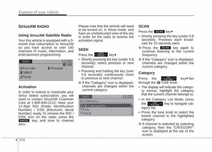
Features of your vehicle
1724
SiriusXM RADIO
Using SiriusXM Satellite RadioYour Kia vehicle is equipped with a 3-month trial subscription to SiriusXMso you have access to over 140channels of music, information, andentertainment programming.
ActivationIn order to extend or reactivate yourSirius Select subscription, you willneed to contact SiriusXM CustomerCare at 1-800-643-2112. Have your12-digit RID (Radio IdentificationNumber) / ESN (Electronic SerialNumber) ready. To retrieve the RID /ESN, turn on the radio, press the
key, and tune to channelzero.
Please note that the vehicle will needto be turned on, in Sirius mode, andhave an unobstructed view of the skyin order for the radio to receive theactivation signal.
SEEKPress the key• Shortly pressing the key (under 0.8
seconds): select previous or nextchannel.
• Pressing and holding the key (over0.8 seconds): continuously moveto previous or next channel.
❈ If the “Category” icon is displayed,channels are changed within thecurrent category.
SCANPress the key• Shortly pressing the key (under 0.8
seconds): Previews each broad-cast for 10 seconds each
❈ Press the key again tocontinue listening to the currentfrequency
❈ If the “Category” icon is displayed,channels are changed within thecurrent category.
CategoryPress the key Setthrough the TUNE knob• The display will indicate the catego-
ry menus, highlight the categorythat the current channel belongs to.
• In the Category List Mode, pressthe key to navigate cat-egory list.
• Press the tune knob to select thelowest channel in the highlightedcategory.
❈ If channel is selected by selectingcategory, then the “CATEGORY”icon is displayed at the top of thescreen.
CATFOLDER
CATFOLDER
SCAN
SCAN
SEEKTRACK
RADIO

4 173
Features of your vehicle
PresetPress the key ~ • Briefly pressing the key (under 0.8
seconds): Plays the frequencysaved in the corresponding key.
• Pressing and holding the key (over0.8 seconds): Pressing and holdingthe desired key from ~ will save the current broadcast tothe selected key and sound aBEEP.
✽✽ Troubleshooting1. Antenna Error
If this message is displayed, the anten-na or antenna cable is broken orunplugged. Please consult with yourKia dealership.
2. No SignalIf this message is displayed, it meansthat the antenna is covered and thatthe SiriusXM Satellite Radio signal isnot available. Ensure the antenna isuncovered and has a clear view of thesky.
Tune• Rotate TUNE knob : Changes
the channel number or scrolls cat-egory list.
• Press TUNE knob : Selects themenu.
MenuSelect category menu through the
TUNE knob Press the keySelect [ Info] through the TUNE
knob or key
Info (Information)Displays the Artist/Song info of thecurrent song.
1 RPT
MENU
61
61RADIO

Features of your vehicle
1744
BASIC METHOD OF USE :USB / iPod® / My Music
Press the key to change themode in order of USB(iPod®) ➟ AUX➟ My Music ➟ BT Audio.The folder/file name is displayed onthe screen.
<USB>
<My Music>
❈ The USB music is automaticallyplayed when a USB is connected.
RepeatWhile song (file) is playing(RPT) keyUSB, iPod®, My Music mode: RPT onscreen• To repeat one song (press the key)
: Repeats the current song.USB mode: FLD.RPT on screen• To repeat folder (pressing twice):
repeats all files within the currentfolder.
❈ Press the key again to turnoff repeat.
RandomWhile song (file) is playing(RDM) keyMy Music mode: RDM on screen• Random (press the key) : Plays all
songs in random order.USB mode: FLD.RDM on screen• Folder Random (press the key) :
Plays all files within the currentfolder in random order.
iPod® mode: ALL RDM on screen• All Random (press the key) : Plays
all files in random order.USB : ALL RDM on screen• All Random (pressing twice): Plays
all files in random order.❈ Press the key again to turn
off random.2 RDM
2 RDM
1 RPT
1 RPT
MEDIA

4 175
Features of your vehicle
Changing Song/FileWhile song (file) is playing
key• Shortly pressing the key : Plays the
current song from the beginning.❈ If the key is pressed
again within 2 second, the previ-ous song is played.
• Pressing and holding the key (over0.8 seconds): Rewinds the song.
While song (file) is playingkey
• Shortly pressing the key : Plays thenext song.
• Pressing and holding the key (over0.8 seconds) : Fast forwards thesong.
ScanWhile song (file) is playingkey• Shortly pressing the key : Scans all
songs from the next song for 10seconds each.
❈ Press the key again to turnoff.
❈ The SCAN function is not support-ed in iPod® mode.
Folder Search : USB ModeWhile file is playing(Folder Up) key• Searches the next folder.While file is playing(Folder Down) key• Searches the parent folder.❈ If a folder is selected by pressing
the TUNE knob, the first filewithin the selected folder will beplayed.
❈ In iPod® mode, moves to theParent Folder.
Searching Songs (File)• Turning TUNE knob : Searches
for songs (files)• Pressing TUNE knob : Plays
selected song (file).
CATFOLDER
CATFOLDER
SCAN
SCAN
SEEKTRACK
SEEKTRACK
SEEKTRACK

Features of your vehicle
1764
MENU : USBPress the USB mode key toset the Repeat, Folder Random,Folder Repeat, All Random,Information, and Copy features.
RepeatPress the key Set [ RPT]through the TUNE knob or key to repeat the current song.❈ Press RPT again to turn off.
Folder RandomPress the key Set [ F.RDM]through the TUNE knob or key to randomly play songs within thecurrent folder.❈ Press F.RDM again to turn off.
Folder RepeatPress the key Set [ F.RPT]through the TUNE knob or key to repeat songs within the cur-rent folder.❈ Press F.RPT again to turn off.
All RandomPress the key Set [ A.RDM]through the TUNE knob or keyto randomly play all songs within theUSB.❈ Press A.RDM again to turn off.
InformationPress the key Set [ Info]through the TUNE knob or key to display information of the cur-rent song.❈ Press the key to turn off
info display.MENU
5MENU
4MENU
3MENU
2 RDM
MENU
1 RPT
MENU
MENU
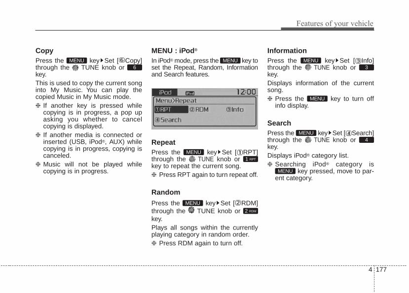
4 177
Features of your vehicle
CopyPress the key Set [ Copy]through the TUNE knob or key.This is used to copy the current songinto My Music. You can play thecopied Music in My Music mode.❈ If another key is pressed while
copying is in progress, a pop upasking you whether to cancelcopying is displayed.
❈ If another media is connected orinserted (USB, iPod®, AUX) whilecopying is in progress, copying iscanceled.
❈ Music will not be played whilecopying is in progress.
MENU : iPod®
In iPod® mode, press the key toset the Repeat, Random, Informationand Search features.
RepeatPress the key Set [ RPT]through the TUNE knob or key to repeat the current song.❈ Press RPT again to turn repeat off.
RandomPress the key Set [ RDM]through the TUNE knob or key.Plays all songs within the currentlyplaying category in random order.❈ Press RDM again to turn off.
InformationPress the key Set [ Info]through the TUNE knob or key.Displays information of the currentsong.❈ Press the key to turn off
info display.
SearchPress the key Set [ Search]through the TUNE knob or key.Displays iPod® category list.❈ Searching iPod® category is
key pressed, move to par-ent category.MENU
4MENU
MENU
3MENU
2 RDM
MENU
1 RPT
MENU
MENU6
MENU

Features of your vehicle
1784
MENU : My Music Mode
In My Music mode, press the key to set the Repeat, Random,Information, Delete, Delete All, andDelete Selection features.
RepeatPress the key Set [ RPT]through the TUNE knob or key.Repeats the currently playing song.❈ Press RPT again to turn repeat off.
RandomPress the key Set [ RDM]through the TUNE knob or key.Plays all songs in random order.❈ Press RDM again to turn random off.
InformationPress the key Set [ Info]through the TUNE knob or key.Displays information of the currentsong.❈ Press the key to turn off
info display.
DeletePress the key Set [ Delete]through the TUNE knob or key.• Deletes currently playing fileIn the play screen, pressing deletewill delete the currently playing song.• Deletes file from list
➀ Select the file you wish to deleteby using the TUNE knob.
➁ Press the key and selectthe delete menu to delete theselected file.
Delete AllPress the key Set [ Del.All]through the TUNE knob or key.Deletes all songs of My Music.
5MENU
MENU
4MENU
MENU
3MENU
2 RDM
MENU
1 RPT
MENU
MENU

4 179
Features of your vehicle
Delete SelectionPress the key Set [ Del.Sel]through the TUNE knob or key.Songs within My Music are selectedand deleted.➀ Select the songs you wish to
delete from the list.
➁ After selecting, press keyand select the delete menu.
My Music• Even if memory is available, a
maximum of 6,000 songs can bestored.
• The same song can be copied upto 1,000 times.
• Memory info can be checked in theSystem menu of Setup.
AUXAUX is used to play external MEDIAcurrently connected with the AUXterminal.AUX mode will automatically startwhen an external device is connect-ed with the AUX terminal.If an external device is connected,you can also press the key tochange to AUX mode.
❈ AUX mode cannot be startedunless there is an external deviceconnected to the AUX terminal.
AUXFully insert the AUX cable into theAUX terminal for use.
MEDIA
MENU
6MENU

Features of your vehicle
1804
Bluetooth® Wireless TechnologyAUDIO (if equipped)
What is Bluetooth® WirelessTechnology?Bluetooth® Wireless Technologyallows devices to be connected in ashort distance, including hands-freedevices, stereo headsets, wirelessremote controllers, etc. For moreinformation, visit the Bluetooth®
Wireless Technology website atwww.Bluetooth.com
Before using Bluetooth® WirelessTechnology audio features• Bluetooth® Wireless Technology
audio may not be supporteddepending on the compatibility ofyour Bluetooth® WirelessTechnology mobile phone.
• In order to use Bluetooth® WirelessTechnology audio, you must firstpair and connect the Bluetooth®
Wireless Technology mobile phone.• The Bluetooth® word mark and logos
are registered trademarks owned byBluetooth SIG, Inc. and any use ofsuch marks by Kia is under license.Other trademarks and trade namesare those of their respective owners.A Bluetooth® enabled cell phone isrequired to use Bluetooth® WirelessTechnology
WARNINGDriving while distracted canresult in a loss of vehicle controlthat may lead to an accident,severe personal injury, anddeath. The driver’s primaryresponsibility is in the safe andlegal operation of a vehicle, anduse of any handheld devices,other equipment, or vehicle sys-tems which take the driver’seyes, attention and focus awayfrom the safe operation of a vehi-cle or which are not permissibleby law should never be used dur-ing operation of the vehicle.

4 181
Features of your vehicle
• Bluetooth® Wireless Technologyaudio can be used only when the[Audio Streaming] of Phone isturned .
Starting Bluetooth® WirelessTechnology Audio• Press the key to change
the mode in order of USB➟AUX➟My Music➟BT Audio.
• If BT Audio is selected, Bluetooth®
Wireless Technology audio will startplaying.
❈ Audio may not automatically startplaying in some mobile phones.
Using the Bluetooth® WirelessTechnology audio features• Play / StopPress the TUNE knob to play andpause the current song.
❈ The title / artist info may not besupported in some mobile phone.When it is not supported, notitle/no artist will be displayed.
• Previous / Next songPress or to playprevious or next song.❈ The previous song / next song /
play / pause functions may not besupported in some mobilephones.
SEEKTRACK
SEEKTRACK
MEDIAOn

Features of your vehicle
1824
PHONE(IF EQUIPPED)
Before using the Bluetooth® WirelessTechnology phone features• In order to use Bluetooth® Wireless
Technology phone, you must firstpair and connect the Bluetooth®
Wireless Technology mobile phone.• If the mobile phone is not paired or
connected, it is not possible toenter Phone mode. Once a phoneis paired or connected, the guid-ance screen will be displayed.
• If Priority is set upon vehicle igni-tion (IGN/ACC ON), the Bluetooth®
Wireless Technology phone will beautomatically connected. Even ifyou are outside, the Bluetooth®
Wireless Technology phone will beautomatically connected once youare in the vicinity of the vehicle. Ifyou do not want automaticBluetooth® Wireless Technologyphone connection, set theBluetooth® Wireless Technologypower to OFF.
Making a call using theSteering-wheel mounted controls
(1) VOLUME key : Raises or lowersspeaker volume.
(2) key : Activates voice recogni-tion.
(3) key : Places and transfers calls.
(4) key : Ends calls or cancels functions.
• Check call history and making call- Shortly press (less than 0.8 sec-
onds) the key on the steeringremote controller.
- The call history list will be dis-played on the screen.
- Press the key again to con-nect a call to the selected number.
• Redialing the most recently callednumber
- Press and hold (more than 0.8 sec-onds) the key on the steeringremote controller.
- The most recently called number isredialed.
❈ If call history does not exist, ascreen asking whether to down-load call history is displayed. (Thedownload feature may not be sup-ported in some mobile phones)

4 183
Features of your vehicle
Bluetooth® Wireless Technology
Pairing a Bluetooth® WirelessTechnology Device(if equipped)
What is Bluetooth® WirelessTechnology Pairing?Pairing refers to the process of syn-chronizing your Bluetooth® WirelessTechnology phone or device with thecar audio system for connection.Pairing is necessary to connect anduse the Bluetooth® WirelessTechnology feature.The Bluetooth® word mark and logosare registered trademarks owned byBluetooth SIG, Inc. and any use ofsuch marks by Kia is under license.Other trademarks and trade namesare those of their respective owners.A Bluetooth® enabled cell phone isrequired to use Bluetooth® WirelessTechnology
WARNINGDriving while distracted canresult in a loss of vehicle controlthat may lead to an accident,severe personal injury, anddeath. The driver’s primaryresponsibility is in the safe andlegal operation of a vehicle, anduse of any handheld devices,other equipment, or vehicle sys-tems which take the driver’seyes, attention and focus awayfrom the safe operation of a vehi-cle or which are not permissibleby law should never be used dur-ing operation of the vehicle.

Features of your vehicle
1844
Pairing key / keyon the Steering RemoteController
When No Devices have beenPaired1.Press the key or the
key on the steering remote controller.The following screen is displayed.
2.Select [OK] button to enter the PairPhone screen.
1) Vehicle Name : Name of device asshown when searching from yourBluetooth® Wireless Technologydevice
2) Passkey : Passkey used to pair thedevice
3.From your Bluetooth® WirelessTechnology device (i.e. MobilePhone), search and select your caraudio system.
[Non SSP supported device](SSP: Secure Simple Pairing)4.After a few moments, a screen is
displayed where the passkey isentered. Enter the passkey “0000”to pair your Bluetooth® WirelessTechnology device with the caraudio system.
[SSP supported device]4.After a few moments, a screen is
displayed 6 digits passkey.Check the passkey on yourBluetooth® Wireless Technologydevice and confirm.
5.Once pairing is complete, the fol-lowing screen is displayed.
PHONE
PHONE
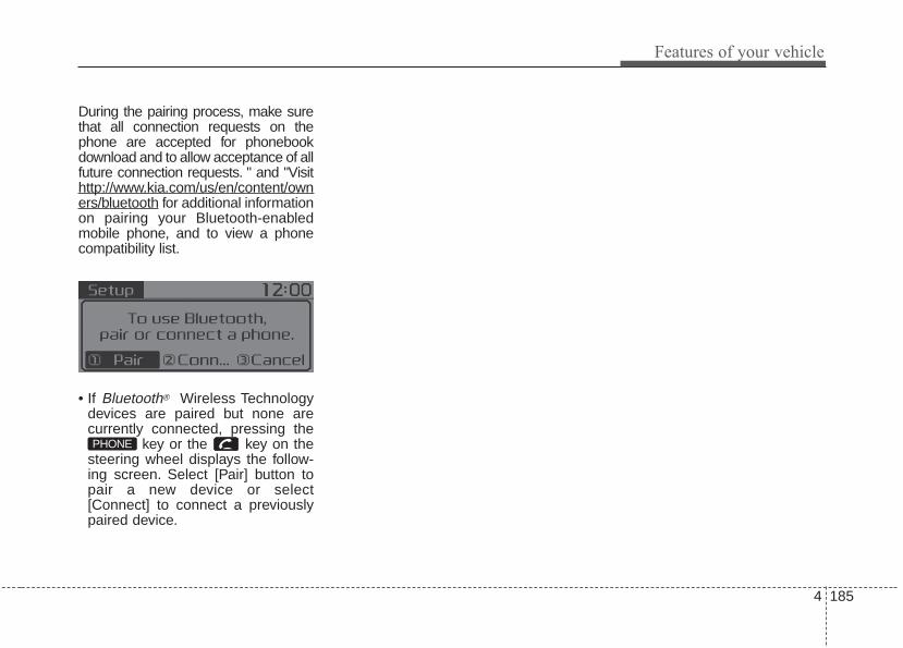
4 185
Features of your vehicle
During the pairing process, make surethat all connection requests on thephone are accepted for phonebookdownload and to allow acceptance of allfuture connection requests. " and "Visithttp://www.kia.com/us/en/content/owners/bluetooth for additional informationon pairing your Bluetooth-enabledmobile phone, and to view a phonecompatibility list.
• If Bluetooth® Wireless Technologydevices are paired but none arecurrently connected, pressing the
key or the key on thesteering wheel displays the follow-ing screen. Select [Pair] button topair a new device or select[Connect] to connect a previouslypaired device.
PHONE

Features of your vehicle
1864
Pairing through [PHONE]Setup
Press the key Select[Phone] Select [Pair Phone] Select TUNE knob
1. The following steps are the sameas those described in the section"When No Devices have beenPaired" on the previous page.
• Bluetooth® Wireless Technologyfeatures supported within the vehi-cle are as follows. Some featuresmay not be supported dependingon your Bluetooth® WirelessTechnology device.- Outgoing/Incoming Handsfree
calls- Operations during a call (Switch
to Private, Switch to call waiting,MIC on/off)
- Downloading Call History- Downloading Mobile Contacts- Bluetooth® Wireless Technology
device auto connection- Bluetooth Audio Streaming
• Up to five Bluetooth® WirelessTechnology devices can be pairedto the Car Handsfree system.
• Only one Bluetooth® WirelessTechnology device can be con-nected at a time.
• Other devices cannot be pairedwhile a Bluetooth® WirelessTechnology device is connected.
• Only Bluetooth® WirelessTechnology Handsfree andBluetooth audio related featuresare supported.
• Bluetooth related operations arepossible only within devices thatsupport Handsfree or audio fea-tures, such as a Bluetooth®
Wireless Technology mobile phoneor a Bluetooth audio device.
• If a connected Bluetooth® WirelessTechnology device becomes dis-connected due to being out ofcommunication range, turning thedevice OFF, or a Bluetooth®
Wireless Technology communica-tion error, correspondingBluetooth® Wireless Technologydevices are automaticallysearched and reconnected.
• If the system becomes unstabledue to communication errorsbetween the car Handsfree and theBluetooth® Wireless Technologydevice, reset the device by turningoff and back on again. Upon reset-ting Bluetooth® WirelessTechnology device, the system willbe restored.
SETUPCLOCK

4 187
Features of your vehicle
• After pairing is complete, a con-tacts download request is sentonce to the mobile phone. Somemobile phones may require confir-mation upon receiving a downloadrequest, ensure your mobile phoneaccepts the connection. Refer toyour phones user’s manual foradditional information regardingphone pairing and connections.
Connecting a Device
Press the key Select[Phone] Select [Phone List]
1) Connected Phone : Device that iscurrently connected
2) Paired Phone : Device that ispaired but not connected
From the paired phone list, select thedevice you want to connect andselect [Connect].
SETUPCLOCK

Features of your vehicle
1884
Changing Priority
What is Priority?It is possible to pair up to fiveBluetooth® Wireless Technologydevices with the car audio system.The "Change Priority" feature is usedto set the connection priority ofpaired phones.
Press the key Select[Phone] Select [Phone List]
From the paired phone list, selectthe phone you want to switch to thehighest priority, then select [ChangePriority] button from the Menu. Theselected device will be changed tothe highest priority.
• Priority icon will be displayed whenthe selected phone is set as a pri-ority phone.
SETUPCLOCK

4 189
Features of your vehicle
Disconnecting a Device
Press the key Select[Phone] Select [Phone List]
From the paired phone list, select thecurrently connected device andselect [Disconnect] button.
Deleting a Device
Press the key Select[Phone] Select [Phone List]
From the paired phone list, select thedevice you want to delete and select[Delete] button.
• When deleting the currently con-nected device, the device will auto-matically be disconnected to pro-ceed with the deleting process.
• If a paired Bluetooth® WirelessTechnology device is deleted, thedevice’s call history and contactsdata will also be deleted.
• To re-use a deleted device, youmust pair the device again.
SETUPCLOCK
SETUPCLOCK

Features of your vehicle
1904
USING Bluetooth® WirelessTechnology(if equipped)
Phone Menu Screen
Phone MenusWith a Bluetooth® Wireless Technologydevice connected, press the key to display the Phone menuscreen.
1) Favorite : Up to 20 frequentlyused contacts saved for easyaccess.
2) Call History : Displays the call his-tory list screen
3) Contacts : Displays the Contactslist screen
4) Setup : Displays Phone relatedsettings.
• If you select the [Call History] but-ton but there is no call history data,a prompt is displayed which asks todownload call history data.
• If you select the [Contacts] buttonbut there is no contacts datastored, a prompt is displayed whichasks to download contacts data.
• This feature may not be supportedin some mobile phones. For moreinformation on download support,refer to your mobile phone user’smanual.
Answering Calls
Answering a CallAnswering a call with a Bluetooth®
Wireless Technology device connect-ed will display the following screen.To accept the call, press key onthe steering wheel while the call isincoming.
1) Caller : Displays the other caller'sname when the incoming caller issaved within your contacts
2) Incoming Number : Displays theincoming number
PHONE

4 191
Features of your vehicle
✽✽ NOTICE• When an incoming call pop-up is
displayed, most Audio and SETUPmode features are disabled. Onlythe call volume will operate.
• The telephone number may not beproperly displayed in some mobilephones.
Favorites
Press the key Select[Favorites]
1) Saved favorite contact : Connectscall upon selection
2) To add favorite : Downloaded con-tacts be saved as favorite.
• To save Favorite, contacts shouldbe downloaded.
• Contact saved in Favorites will notbe automatically updated if thecontact has been updated in thephone. To update Favorites, deletethe Favorite and create a newFavorite.
Call History
Press the key Select [CallHistory]
A list of incoming, outgoing andmissed calls is displayed.• Call history may not be saved in the
call history list in some mobilephones.
• Calls received with hidden caller IDwill not be saved in the call historylist.
• Calling through the call history is notpossible when there is no call histo-ry stored or a Bluetooth® WirelessTechnology phone is not connected.
• Up to 50 received, dialed andmissed calls are stored in CallHistory.
• Time of received/dialed calls andcall time information are not storedin Call History.
PHONE PHONE

Features of your vehicle
1924
Contacts
Press the key Select[Contacts]
The list of saved phone book entriesis displayed.
NOTE:Find a contact in an alphabeticalorder, press the key.
• Up to 1,000 contacts saved in yourBluetooth® Wireless Technologyphone can be downloaded into thecar contacts. Contacts that havebeen downloaded to the car cannotbe edited or deleted on the phone.
• Mobile phone contacts are man-aged separately for each pairedBluetooth® Wireless Technologydevice (max 5 devices x 1,000 con-tacts each). Previously down-loaded data is maintained even ifthe Bluetooth® Wireless Technologydevice has been disconnected.(However, the contacts and call his-tory saved to the phone will be delet-ed if a paired phone is deleted.)
• It is possible to download contactsduring Bluetooth streaming audio.
• When downloading contacts, theicon will be displayed within thestatus bar.
• It is not possible to begin down-loading a contact list when the con-tact download feature has beenturned off within the Bluetooth®
Wireless Technology device. Inaddition, some devices mayrequire device authorization uponattempting to download contacts. Ifdownloading does not normallyoccur, check the Bluetooth®
Wireless Technology device set-tings or the screen state.
• The contacts download featuremay not be supported in somemobile phones. For more informa-tion of supported Bluetooth®
devices and function support, referto your phone’s user manual.
MENU
PHONE

4 193
Features of your vehicle
Bluetooth® WirelessTechnology Setting
The Bluetooth® word mark and logosare registered trademarks owned byBluetooth SIG, Inc. and any use ofsuch marks by Kia is under license.Other trademarks and trade namesare those of their respective owners.A Bluetooth® enabled cell phone isrequired to use Bluetooth® WirelessTechnology.
Pairing a New DevicePress the key Select[Phone] Select [Pair Phone]
Bluetooth® Wireless Technologydevices can be paired with the audiosystem.For more information, refer to the“Pairing through Phone Setup” sec-tion within Bluetooth® WirelessTechnology.
Viewing Paired Phone ListPress the key Select[Phone] Select [Phone List]
This feature is used to view mobilephones that have been paired withthe audio system. Upon selecting apaired phone, the setup menu is dis-played.For more information, refer to the“Setting Bluetooth® WirelessTechnology Connection” section withinBluetooth® Wireless Technology.
SETUPCLOCK
SETUPCLOCK
WARNINGDriving while distracted canresult in a loss of vehicle controlthat may lead to an accident,severe personal injury, anddeath. The driver’s primaryresponsibility is in the safe andlegal operation of a vehicle, anduse of any handheld devices,other equipment, or vehicle sys-tems which take the driver’seyes, attention and focus awayfrom the safe operation of a vehi-cle or which are not permissibleby law should never be used dur-ing operation of the vehicle.

Features of your vehicle
1944
1) Connect/Disconnect Phone :Connect/ disconnects currentlyselected phone
2) Change Priority : Sets currentlyselected phone to highest connec-tion priority
3) Delete : Deletes the currentlyselected phone
4) Return : Moves to the previousscreen
• To learn more about whether yourmobile phone supports contactsdownloads, refer to your mobilephone user’s manual.
• The contacts for only the connect-ed phone can be downloaded
Downloading ContactsPress the key Select[Phone] Select [Contacts Download]
As the contacts are downloadedfrom the mobile phone, a downloadprogress bar is displayed.
• Upon downloading phone con-tacts, the previous correspondingdata is deleted.
• This feature may not be supportedin some mobile phones.
• Voice Recognition may not operatewhile contacts are being down-loaded.
Outgoing VolumePress the key Select[Phone] Select [Outgoing Volume]
Use TUNE knob to adjust the out-going volume level.
• While on a call, the volume can bechanged by using the key.
SEEKTRACK
SETUPCLOCK
SETUPCLOCK

4 195
Features of your vehicle
Turning Bluetooth System OffPress the key Select[Phone] Select [Bluetooth SystemOff]Once Bluetooth® Wireless Technologyis turned off, Bluetooth® WirelessTechnology related features will notbe supported within the audio sys-tem.
• To turn Bluetooth® WirelessTechnology back on, go to
[Phone] and select “Yes”.SETUP
CLOCK
SETUPCLOCK

Features of your vehicle
1964
VOICE RECOGNITION
Using Voice Recognition
Starting Voice RecognitionShortly press the key on thesteering wheel. Say a command
If prompt feedback is in [ON], thenthe system will say “Please say acommand after the beep (BEEP)”• If prompt feedback is in [OFF]
mode, then the system will onlysay “(BEEP)”
• To change Prompt Feedback[On]/[Off], go to [System]
[Prompt Feedback]• For proper recognition, say the
command after the voice instruc-tion and beep tone.
Skipping Prompt MessagesWhile prompt message is being stat-ed Shortly press the key on thesteering remote controllerThe prompt message is immediatelyended and the beep tone will sound.After the “beep”, say the voice com-mand.
Re-starting Voice RecognitionWhile system waits for a commandShortly press the key on thesteering remote controllerThe command wait state is immedi-ately ended and the beep ton willsound. After the “beep”, say the voicecommand.
SETUPCLOCK

4 197
Features of your vehicle
ENDING VOICERECOGNITION
While Voice Recognition is operatingPress and hold the key on the
steering remote controller
• While using voice command,pressing any steering wheel con-trol or a different key will end voicecommand.
• When the system is waiting for avoice command, say “cancel” or“end” to end voice command.
• When the system is waiting for avoice command, press and holdthe key on the steering wheelto end voice command.
Voice Recognition and PhoneContact Tips:The Kia Voice Recognition Systemmay have difficulty understandingsome accents or uncommonnames. When using VoiceRecognition to place a call, speak ina moderate tone, with clear pronun-ciationTo maximize the use of VoiceRecognition, consider these guide-lines when storing contacts:• Do not store single-name entries
(e.g., “Bob”, “Mom”, etc.). Instead,always use full names (includingfirst and last names) for these con-tacts
• Do not use special characters(e.g., '@', '-', '*', '&', etc.)
• Do not use abbreviations (i.e., use"Lieutenant" instead of "Lt.") oracronyms (i.e., use "CountyFinance Department" instead of"C. F. D."; Be sure to say the nameexactly as it is entered in the con-tacts list
• Do not use acronyms (i.e., use“County Finance Department”instead of “CFD”).
• If a name is not recognized fromthe contact list, change it to a moredescriptive name (e.g., use“Grandpa Joseph” instead of “PaJoe”).

Features of your vehicle
1984
Illustration on using voice commands
• Starting voice command.Shortly pressing the key (under 0.8 seconds):
• Skipping Prompt MessagesShortly pressing the key (under 0.8 seconds):
Shortly pressing the key (under 0.8 seconds):
• Ending voice command.Shortly pressing the key (under 0.8 seconds):
while guidance message isbeing stated
More Help
Contacts
Cancel
More Help
Please say a command afterthe beep (BEEP)
Please say a...
Please say the contact name you want to call.
Please say a command after the beep (BEEP)
Beep~
More HelpHere are some examples of mode commands.You can say a radio type like 'FM', 'AM', or 'Satellite'.You can also say a media source like 'USB', 'MyMusic', or 'iPod'.Additionally, there are phone commands like"Contacts', 'Call History', or 'Dial Number".You can find more detailed commands in the user'smanual.Please say a command after the beep.
More HelpHere are some examples of mode commands.You can say a radio type like 'FM', 'AM', or 'Satellite'.You can also say a media source like 'USB', 'MyMusic', or 'iPod'.Additionally, there are phone commands like"Contacts', 'Call History', or 'Dial Number". You canfind more detailed commands in the user's manual.Please say a command after the beep.
(BEEP)

4 199
Features of your vehicle
Voice Command List• Common Commands: These commands can be used in most operations. (However a few commands may not be
available during certain operations)
Command FunctionMore Help Provides guidance on commands that can be
used anywhere in the system.
Help Provides guidance on commands that can beused within the current mode.
Call<Name> Calls <Name> saved in ContactsEx) Call “John Smith”
Call <Name> Calls <Name> to the number that is saved as"Mobile" in Contacts Ex) Call "John Smith" on Mobile
Call <Name> Calls <Name> to the number that is saved as"Office" in Contacts Ex) Call "John Smith" in Office
Call <Name> Calls <Name> to the number that is saved as "Home" in Contacts Ex) Call "John Smith" at Home
Call <Name> Calls <Name> to the number that is saved as "Other" in Contacts Ex) Call "John Smith" on Other
Phone Provides guidance on Phone related com-mands. After saying this command, say“Favorites”,“Call History”, “Contacts” or ”DialNumber” execute corresponding functions.
Favorites Displays the Favorite screen.
Call History Displays the Call History screen.
Command FunctionContacts Displays the Contacts screen. After saying
this command, say the name of a contactsaved in the Contacts to automatically con-nect the call.
Dial Number Displays the Dial number screen. After sayingthis command, you can say the number thatyou want to call.
Redial Connects the last dialed call number.
Tutorial Provides guidance on how to use voice recognition and Bluetooth® connections
• When listening to the radio, displays the nextradio screen. (FM1➟FM2➟AM➟SAT1➟
SAT2➟SAT3➟FM1)
Radio • When listening to a different mode, displaysthe most recently played radio screen.
• When currently listening to the FM radio, main-tains the current state.
• When listening to a different mode, displaysthe most recently played FM screen.
FM1(FM One) Displays the FM1 screen.
FM2(FM Two) Displays the FM2 screen.
AM Displays the AM screen.
on Mobile
in Office
at Home
on Other

Features of your vehicle
2004
Command FunctionFM Preset 1~6 Plays the most recently played broadcast
saved in FM Preset 1~6.
AM Preset 1~6 Plays the broadcast saved in AM Preset 1~6.
FM 87.5~107.9 Plays the FM broadcast of the correspondingfrequency.
AM 530~1710 Plays the AM broadcast of the correspondingfrequency.
SIRIUS (Satellite) • When currently listening to the SiriusXM®,maintains the current state.
• When listening to a different mode, displaysthe most recently played SiriusXM® screen.
SIRIUS (Satellite) Displays the selected SiriusXM® screen.
SIRIUS Channel Plays the selected SiriusXM® channel.
Media Moves to the most recently played mediascreen.
USB Plays USB music.
iPod® Plays iPod® music.
Command FunctionMy Music Plays the music saved in My Music.
AUX (Auxiliary) Plays the connected external device.
Bluetooth® Audio Plays the music saved in connected Bluetooth®
device.
Mute Mutes the sound.
Cancel (Exit) Ends voice command.
0~223
1~3

4 201
Features of your vehicle
• FM/AM radio commands: Commands available duringFM, AM radio operation.
• Satellite radio commands: Commands that can beused while listening to Satellite Radio.
Command FunctionPreset 1~6 Plays the broadcast station saved in Preset 1~6.
Scan Scans receivable frequencies from the currentbroadcast and plays for 10 seconds each.
Preset Scan Moves to the next preset from the currentpresent and plays for 10 seconds each.
Information Displays the information of the current broad-cast.(This feature can be used when receivingRBDS broadcasts.)
Command FunctionChannel 0~223 Plays the selected Satellite Radio channel.
Scan Scans receivable channels from the currentbroadcast and plays for 10 seconds each.
Preset 1~6 Plays the broadcast saved in Preset 1~6.
Information Displays the information of the current broad-cast.

Features of your vehicle
2024
• USB commands: Commands available during USBoperation.
• iPod® Commands: Commands available during iPod®
operation.
Command FunctionRandom Randomly plays the files within the current
folder.
Random Off Cancels random play to play files in sequentialorder.
Repeat Repeats the current file.
Repeat Off Cancels repeat play to play files in sequentialorder.
Information Displays the information screen of the currentfile.
Next Folder Play the first file in the next folder.
Previous Folder Play the first file in the previous folder.
Command FunctionRandom Randomly plays the songs within the current
category.
Random Off Cancels random play to play songs in sequen-tial order.
Repeat Repeats the current song.
Repeat Off Cancels repeat play to play songs in sequen-tial order.

4 203
Features of your vehicle
• My Music Commands: Commands available duringMy Music operation.
• Bluetooth® Wireless Technology Audio Commands:Commands available during Bluetooth® WirelessTechnology audio streaming from mobile phone oper-ation Command Operation.
Command FunctionRandom Randomly plays all saved files.
Random Off Cancels random play to play files in sequentialorder.
Repeat Repeats the current file.
Repeat Off Cancels repeat play to play files in sequentialorder.
Delete Deletes the current file. You will bypass anadditional confirmation process.
Command FunctionPlay Plays the currently paused song.
Pause Pauses the current song.
Features of your vehicle
2044
iPod® is a registered trademark of Apple Inc. iPod®
mobile digital device sold separately. TheBluetooth® word mark and logos are registeredtrademarks owned by Bluetooth SIG, Inc. and anyuse of such marks by Kia is under license.SiriusXM services require a subscription sold sep-arately, or as a package, by Sirius XM Radio Inc. Ifyou decide to continue service after your trial, thesubscription plan you choose will automaticallyrenew thereafter and you will be charged accordingto your chosen payment method at then-currentrates. Fees and taxes apply.To cancel you must callSiriusXM at 1-866-635-2349. See SiriusXMCustomer Agreement for complete terms atwww.siriusxm.com. SiriusXM U.S. satellite and dataservices are available only in the 48 contiguousUSA, DC and PR (with coverage limitations).SiriusXM satellite service is also available inCanada; see www.siriusxm.ca. All fees and pro-gramming subject to change. Sirius, XM and allrelated marks and logos are trademarks of SiriusXM Radio Inc. Android™ is a trademark of Google,Inc. BlackBerry is a registered trademark ofResearch In Motion Limited (RIM). All other marks,channel names and logos are the property of theirrespective owners. All rights reserved.
4 205
Features of your vehicle
IC
This device complies with Industry Canada’s licence-exempt RSSs.Operation is subject to the following two conditions:(1) This device may not cause interference; and(2) This device must accept any interference, including interference that may cause undesired operation of the device.
Le présent appareil est conforme aux CNR d'Industrie Canada applicables aux appareils radio exempts de licence.L'exploitation est autorisée aux deux conditions suivantes : (1) l'appareil ne doit pas produire de brouillage, et (2) l'utilisateur de l'appareil doit accepter tout brouillage radioélectrique subi, même si le brouillage est susceptibled'en compromettre le fonctionnement.

Features of your vehicle
2064
■■ AUDIO : AM1A0B2AN, AM1A0B2KN
PS34001N
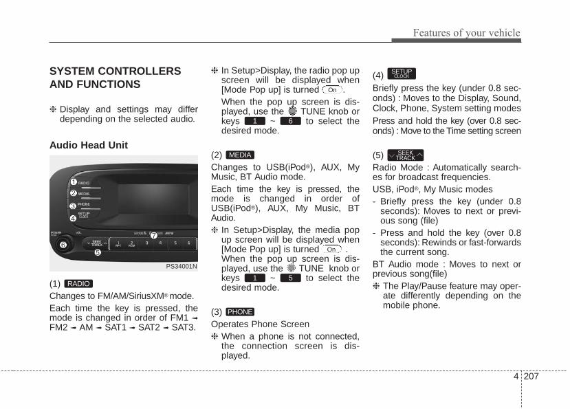
4 207
Features of your vehicle
SYSTEM CONTROLLERSAND FUNCTIONS
❈ Display and settings may differdepending on the selected audio.
Audio Head Unit
(1) Changes to FM/AM/SiriusXM® mode.Each time the key is pressed, themode is changed in order of FM1 ➟
FM2 ➟ AM ➟ SAT1 ➟ SAT2 ➟ SAT3.
❈ In Setup>Display, the radio pop upscreen will be displayed when[Mode Pop up] is turned .When the pop up screen is dis-played, use the TUNE knob orkeys ~ to select thedesired mode.
(2) Changes to USB(iPod®), AUX, MyMusic, BT Audio mode.Each time the key is pressed, themode is changed in order ofUSB(iPod®), AUX, My Music, BTAudio.❈ In Setup>Display, the media pop
up screen will be displayed when[Mode Pop up] is turned .When the pop up screen is dis-played, use the TUNE knob orkeys ~ to select thedesired mode.
(3) Operates Phone Screen❈ When a phone is not connected,
the connection screen is dis-played.
(4) Briefly press the key (under 0.8 sec-onds) : Moves to the Display, Sound,Clock, Phone, System setting modesPress and hold the key (over 0.8 sec-onds) : Move to the Time setting screen
(5) Radio Mode : Automatically search-es for broadcast frequencies.USB, iPod®, My Music modes- Briefly press the key (under 0.8
seconds): Moves to next or previ-ous song (file)
- Press and hold the key (over 0.8seconds): Rewinds or fast-forwardsthe current song.
BT Audio mode : Moves to next orprevious song(file)❈ The Play/Pause feature may oper-
ate differently depending on themobile phone.
SEEKTRACK
SETUPCLOCK
PHONE
51
On
MEDIA
61
On
RADIO
PS34001N

Features of your vehicle
2084
(6) PWR/VOL knobPower : Turns power On/Off by
pressing the knobVolume : Sets volume by turning
the knob left/right
(7) ~ (Preset)Radio mode: Saves frequencies(channels) or receives saved fre-quencies (channels)USB, iPod®, My Music mode- : Repeat- : RandomIn the Radio, Media, Setup, andMenu pop up screen, the numbermenu is selected.
(8) Each time the button is pressed, itsets the screen Off ➟ Screen On ➟
Screen Off❈ Audio operation is maintained and
only the screen will be turned Off.In the screen Off state, press anykey to turn the screen On again.
(9) Radio mode- Shortly press the key : Previews
each broadcast for 5 secondseach.
- Press and hold the key (over 0.8seconds): Previews the broadcastssaved in Preset ~ for 5seconds each.
❈ Press the key again tocontinue listening to the currentfrequency.
❈ SAT Radio does not support thePreset scan feature.
USB, My Music mode- Briefly press the key (under 0.8
seconds): Previews each song(file) for 10 seconds each.
❈ Press the key again tocontinue listening to the currentsong (file).
(10) Displays menus for the current mode.❈ iPod List : Move to parent category
MENU
SCAN
SCAN
61
SCAN
DISP2 RDM
1 RPT
61
PS34001N

4 209
Features of your vehicle
(11) Go to previous menu (no previousscreen)
(12) Radio mode- SiriusXM® RADIO : Category
Search- USB mode : Folder Search
(13) TUNE knobAM/FM mode :- Changes frequency by turning the
knob left/right.SiriusXM® Radio Mode:- Changes the station by turning the
knob left/right. Press knob toselect station.
USB, iPod®, My Music mode:- Searches songs (files) by turning
the knob left/right.❈ When the desired song is displayed,
press the knob to play the song.Moves focus in all selection menusand selects menus.
CATFOLDER
BACK
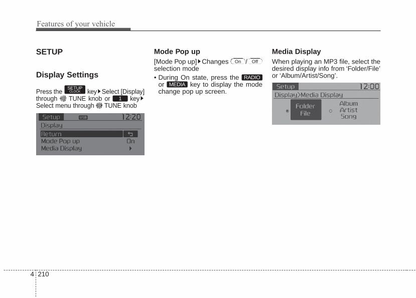
Features of your vehicle
2104
SETUP
Display Settings
Press the key Select [Display]through TUNE knob or keySelect menu through TUNE knob
Mode Pop up[Mode Pop up] Changes /selection mode• During On state, press the
or key to display the modechange pop up screen.
Media DisplayWhen playing an MP3 file, select thedesired display info from ‘Folder/File’or ‘Album/Artist/Song’.
MEDIARADIO
OffOn
1
SETUPCLOCK

4 211
Features of your vehicle
SOUND SETTINGS
Press the key Select [Sound]through TUNE knob or keySelect menu through TUNE knob
Sound SettingsThis menu allows you to set the‘Bass, Middle, Treble’ and the SoundFader and Balance.Select [Sound Settings] Selectmenu through TUNE knob Turn
TUNE knob left/right to set• Bass, Middle, Treble : Selects the
sound tone.• Fader, Balance : Moves the sound
fader and balance.• Default : Restores default settings.❈ Back : While adjusting values,
pressing the TUNE knob willrestore the parent menu.
Speed Dependent Volume ControlThis feature will gradually increasethe volume as speed increases tooffset outside noise.Select [Speed Dependent Vol.] Set[On/Off] of TUNE knob
Voice Recognition VolumeAdjusts voice recognition volume.Select [Voice Recognition Vol.] Setvolume of TUNE knob
2
SETUPCLOCK

Features of your vehicle
2124
CLOCK SETTINGS
Press the key Select [Clock]through TUNE knob or keySelect menu through TUNE knob
Sound SettingsThis menu is used to set the time.Select [Clock Settings] Set through
TUNE knob Press TUNE knob
❈ Adjust the number currently infocus to set the [hour] and pressthe tune knob to set the [minute]and [AM/PM].
Calendar SettingsThis menu is used to set the date(MM/DD/YYYY).Select [Calendar Settings] Set through
TUNE knob Press TUNE knob
❈ Adjust the number currently infocus to make the settings andpress the tune knob to move to thenext setting. (Set in order ofYear/Month/Day)
Time FormatThis function is used to set the12/24 hour time format of theaudio system. Select [TimeFormat] Set 12Hr / 24Hr through
TUNE knob
Clock Display when Power is OFFSelect [Clock Disp.(Pwr Off) Set
/ through TUNE knob
: Displays time/date on screen: Turn off.Off
On
OffOn
3
SETUPCLOCK
WARNING - Clock SettingDistraction
Do not adjust the clock whiledriving. You may lose yoursteering control and causesevere personal injury or acci-dents.

4 213
Features of your vehicle
SYSTEM SETTINGS
Press the key Select[System] Select menu through
TUNE knob
Memory InformationDisplays currently used memory andtotal system memory.Select [Memory Information] OKThe currently used memory is dis-played on the left side while the totalsystem memory is displayed on theright side.
Prompt FeedbackThis feature is used to change voicecommand feedback between Normaland Expert modes.Select [Prompt Feedback] Setthrough TUNE knob• On : This mode is for beginner
users and provides detailedinstructions during voice commandoperation.
• Off : This mode is for expert usersand omits some information duringvoice command operation. (Whenusing Expert mode, guidanceinstructions can be heard throughthe [Help] or [Menu] commands.
LanguageThis menu is used to set the displayand voice recognition language.Select [Language] Set through TUNE knob
❈ The system will reboot after thelanguage is changed.
❈ Language support by region- English, Francais, Espanol
SETUPCLOCK

Features of your vehicle
2144
RADIO : FM, AM OR SIRIUS XM®
SEEKPress the key• Briefly pressing the key (under 0.8
seconds): Automatically searchesfor the next station.
• Pressing and holding the key (over0.8 seconds): While holding the key,frequency changes without stop-ping. When the key is released,automatically searches for the nextfrequency from that point.
Preset SEEKPress the ~ key• Briefly pressing the key (under 0.8
seconds): Plays the frequencysaved in the corresponding key.
• Pressing and holding the key (over0.8 seconds): Pressing and holdingthe desired key from ~ will save the currently playingbroadcast to the selected key andsound a BEEP.
SCANPress the key• Briefly pressing the key (under 0.8
seconds): The broadcast frequencyincreases and previews eachbroadcast for 5 seconds each. Afterscanning all frequencies, returnsand plays the current broadcast fre-quency.
• Pressing and holding the key (over0.8 seconds): Previews the broad-casts saved in Preset ~ for 5 seconds each.
Selecting through manualsearchTurn the TUNE knob left/right toadjust the frequency.• FM : Changes by 200KHz• AM : Changes by 10KHz
61
SCAN
61
61
SEEKTRACK

4 215
Features of your vehicle
MENUWithin key are the A.Store(Auto Store) and Info functions.
A.Store
Press the key Set [A.Store]through TUNE knob or key.Saves broadcasts with superiorreception to ~ keys. If nofrequencies are received, then themost recently received frequency willbe broadcast.
61
1
MENU
MENU

Features of your vehicle
2164
SiriusXM® Satellite Radio informationSatellite Radio channels:Enjoy SiriusXM Satellite Radio with a3-month trial subscription to theSirius Select package. You’ll get over140 channels, including commercial-free music, plus all your favoritesports, exclusive talk, entertainment,and a selection of premium program-ming. For more information and acomplete list of SiriusXM channels,visit siriusxm.com in the UnitedStates, siriusxm.ca in Canada, or callSiriusXM at 1-888-539-7474.
Satellite Radio reception factors:To receive the satellite signal, your vehi-cle has been equipped with a satelliteradio antenna located on the roof ofyour vehicle. The vehicle roof providesthe best location for an unobstructed,open view of the sky, a requirement ofa satellite radio system. Like AM/FM,there are several factors that can affectsatellite radio reception performance:• Antenna obstructions: For optimal
reception performance, keep theantenna clear of snow and icebuild-up and keep luggage andother material as far away from theantenna as possible.
• Terrain: Hills, mountains, tall build-ings, bridges, tunnels, freeway over-passes, parking garages, densetree foliage and thunderstorms caninterfere with your reception.
SiriusXM Satellite Radio serv-ice:SiriusXM is a subscription-based satel-lite radio service that broadcastsmusic, sports, news and entertainmentprogramming to radio receivers, whichare available for installation in motorvehicles or factory installed, as well asfor the home, portable and wirelessdevices, and through an Internet con-nection on personal computer.Vehicles that are equipped with afactory installed SiriusXM SatelliteRadio system include:• Hardware and an introductory trial
subscription term, which begins onthe date of sale or lease of thevehicle.
• For a small upgrade fee, access toSiriusXM music channels, and otherselect channels over the Internetusing any computer connected tothe Internet (U.S. customers only).
For information on extended sub-scription terms, contact SiriusXM at1-888-539-7474.
NOTE:SiriusXM services require a sub-scription sold separately, or as apackage, by Sirius XM Radio Inc. Ifyou decide to continue serviceafter your trial, the subscriptionplan you choose will automatical-ly renew thereafter and you will becharged according to your chosenpayment method at then-currentrates. Fees and taxes apply. Tocancel you must call SiriusXM at1-866-635-2349. See SiriusXMCustomer Agreement for com-plete terms at www.siriusxm.com.SiriusXM U.S. satellite and dataservices are available only in the48 contiguous USA, DC and PR(with coverage limitations).SiriusXM satellite service is alsoavailable in Canada; see www.sir-iusxm. ca. All fees and program-ming subject to change. Sirius,XM and all related marks andlogos are trademarks of Sirius XMRadio Inc. Sirius, XM and all relat-ed marks and logos are trade-marks of Sirius XM Radio Inc.

4 217
Features of your vehicle
SiriusXM RADIO
Using SiriusXM Satellite RadioYour Kia vehicle is equipped with a 3-month trial subscription to SiriusXMso you have access to over 140channels of music, information, andentertainment programming.
ActivationIn order to extend or reactivate yourSirius Select subscription, you willneed to contact SiriusXM CustomerCare at 1-800-643-2112. Have your12-digit RID (Radio IdentificationNumber) / ESN (Electronic SerialNumber) ready. To retrieve the RID /ESN, turn on the radio, press the
key, and tune to channelzero.
Please note that the vehicle will needto be turned on, in Sirius mode, andhave an unobstructed view of the skyin order for the radio to receive theactivation signal.
SEEKPress the key• Shortly pressing the key (under 0.8
seconds): select previous or nextchannel.
• Pressing and holding the key (over0.8 seconds): continuously moveto previous or next channel.
❈ If the “Category” icon is displayed,channels are changed within thecurrent category.
SCANPress the key• Shortly pressing the key (under 0.8
seconds): Previews each broad-cast for 10 seconds each
❈ Press the key again tocontinue listening to the currentfrequency
❈ If the “Category” icon is displayed,channels are changed within thecurrent category.
CategoryPress the key Setthrough the TUNE knob• The display will indicate the catego-
ry menus, highlight the categorythat the current channel belongs to.
• In the Category List Mode, pressthe key to navigate cat-egory list.
• Press the tune knob to select thelowest channel in the highlightedcategory.
❈ If channel is selected by selectingcategory, then the “CATEGORY”icon is displayed at the top of thescreen.
CATFOLDER
CATFOLDER
SCAN
SCAN
SEEKTRACK
RADIO

Features of your vehicle
2184
PresetPress the key ~ • Briefly pressing the key (under 0.8
seconds): Plays the frequencysaved in the corresponding key.
• Pressing and holding the key (over0.8 seconds): Pressing and holdingthe desired key from ~ will save the current broadcast tothe selected key and sound aBEEP.
✽✽ Troubleshooting1. Antenna Error
If this message is displayed, the anten-na or antenna cable is broken orunplugged. Please consult with yourKia dealership.
2. Acquiring SignalIf this message is displayed, it meansthat the antenna is covered and thatthe SIRIUSTM Satellite Radio signal isnot available. Ensure the antenna isuncovered and has a clear view of thesky.
Tune• Rotate TUNE knob : Changes
the channel number or scrolls cat-egory list.
• Press TUNE knob : Selects themenu.
MenuSelect category menu through the
TUNE knob Press the keySelect [ Info] through the TUNE
knob or key
Info (Information)Displays the Artist/Song info of thecurrent song.
1 RPT
MENU
61
61RADIO

4 219
Features of your vehicle
BASIC METHOD OF USE :USB / iPod® / My Music
Press the key to change themod mode in order of USB(iPod®) ➟AUX ➟ My Music ➟ BT Audio.The folder/file name is displayed onthe screen.
<USB>
<My Music>
❈ The USB music is automaticallyplayed when a USB is connected.
RepeatWhile song (file) is playing(RPT) keyUSB, iPod®, My Music mode: RPT onscreen• To repeat one song (press the key)
: Repeats the current song.USB mode: FLD.RPT on screen• To repeat folder (pressing twice):
repeats all files within the currentfolder.
❈ Press the key again to turnoff repeat.
RandomWhile song (file) is playing(RDM) keyMy Music mode: RDM on screen• Random (press the key) : Plays all
songs in random order.USB mode: FLD.RDM on screen• Folder Random (press the key) :
Plays all files within the currentfolder in random order.
iPod® mode: ALL RDM on screen• All Random (press the key) : Plays
all files in random order.USB : ALL RDM on screen• All Random (pressing twice): Plays
all files in random order.❈ Press the key again to turn
off random.2 RDM
2 RDM
1 RPT
1 RPT
MEDIA

Features of your vehicle
2204
Changing Song/FileWhile song (file) is playing
key• Shortly pressing the key : Plays the
current song from the beginning.❈ If the key is pressed
again within 2 second, the previ-ous song is played.
• Pressing and holding the key (over0.8 seconds): Rewinds the song.
While song (file) is playingkey
• Shortly pressing the key : Plays thenext song.
• Pressing and holding the key (over0.8 seconds) : Fast forwards thesong.
ScanWhile song (file) is playingkey• Shortly pressing the key : Scans all
songs from the next song for 10seconds each.
❈ Press the key again to turnoff.
❈ The SCAN function is not support-ed in iPod® mode.
Folder Search : USB ModeWhile file is playing(Folder Up) key• Searches the next folder.While file is playing(Folder Down) key• Searches the parent folder.❈ If a folder is selected by pressing
the TUNE knob, the first filewithin the selected folder will beplayed.
❈ In iPod® mode, moves to theParent Folder.
Searching Songs (File)• Turning TUNE knob : Searches
for songs (files)• Pressing TUNE knob : Plays
selected song (file).
CATFOLDER
CATFOLDER
SCAN
SCAN
SEEKTRACK
SEEKTRACK
SEEKTRACK

4 221
Features of your vehicle
MENU : USBPress the USB mode key toset the Repeat, Folder Random,Folder Repeat, All Random,Information, and Copy features.
RepeatPress the key Set [ RPT]through the TUNE knob or key to repeat the current song.❈ Press RPT again to turn off.
Folder RandomPress the key Set [ F.RDM]through the TUNE knob or key to randomly play songs within thecurrent folder.❈ Press F.RDM again to turn off.
Folder RepeatPress the key Set [ F.RPT]through the TUNE knob or key to repeat songs within the cur-rent folder.❈ Press F.RPT again to turn off.
All RandomPress the key Set [ A.RDM]through the TUNE knob or keyto randomly play all songs within theUSB.❈ Press A.RDM again to turn off.
InformationPress the key Set [ Info]through the TUNE knob or key to display information of the cur-rent song.❈ Press the key to turn off
info display.MENU
5MENU
4MENU
3MENU
2 RDM
MENU
1 RPT
MENU
MENU

Features of your vehicle
2224
CopyPress the key Set [ Copy]through the TUNE knob or key.This is used to copy the current songinto My Music. You can play thecopied Music in My Music mode.❈ If another key is pressed while
copying is in progress, a pop upasking you whether to cancelcopying is displayed.
❈ If another media is connected orinserted (USB, iPod®, AUX) whilecopying is in progress, copying iscanceled.
❈ Music will not be played whilecopying is in progress.
MENU : iPod®
In iPod® mode, press the key toset the Repeat, Random, Informationand Search features.
RepeatPress the key Set [ RPT]through the TUNE knob or key to repeat the current song.❈ Press RPT again to turn repeat off.
RandomPress the key Set [ RDM]through the TUNE knob or key.Plays all songs within the currentlyplaying category in random order.❈ Press RDM again to turn off.
InformationPress the key Set [ Info]through the TUNE knob or key.Displays information of the currentsong.❈ Press the key to turn off
info display.
SearchPress the key Set [ Search]through the TUNE knob or key.Displays iPod® category list.❈ Searching iPod® category is
key pressed, move to par-ent category.MENU
4MENU
MENU
3MENU
2 RDM
MENU
1 RPT
MENU
MENU6
MENU

4 223
Features of your vehicle
MENU : My Music Mode
In My Music mode, press the key to set the Repeat, Random,Information, Delete, Delete All, andDelete Selection features.
RepeatPress the key Set [ RPT]through the TUNE knob or key.Repeats the currently playing song.❈ Press RPT again to turn repeat off.
RandomPress the key Set [ RDM]through the TUNE knob or key.Plays all songs in random order.❈ Press RDM again to turn random off.
InformationPress the key Set [ Info]through the TUNE knob or key.Displays information of the currentsong.❈ Press the key to turn off
info display.
DeletePress the key Set [ Delete]through the TUNE knob or key.• Deletes currently playing fileIn the play screen, pressing deletewill delete the currently playing song.• Deletes file from list
➀ Select the file you wish to deleteby using the TUNE knob.
➁ Press the key and selectthe delete menu to delete theselected file.
Delete AllPress the key Set [ Del.All]through the TUNE knob or key.Deletes all songs of My Music.
5MENU
MENU
4MENU
MENU
3MENU
2 RDM
MENU
1 RPT
MENU
MENU

Features of your vehicle
2244
Delete SelectionPress the key Set [ Del.Sel]through the TUNE knob or key.Songs within My Music are selectedand deleted.➀ Select the songs you wish to
delete from the list.
➁ After selecting, press keyand select the delete menu.
My Music• Even if memory is available, a
maximum of 6,000 songs can bestored.
• The same song can be copied upto 1,000 times.
• Memory info can be checked in theSystem menu of Setup.
AUXAUX is used to play external MEDIAcurrently connected with the AUXterminal.AUX mode will automatically startwhen an external device is connect-ed with the AUX terminal.If an external device is connected,you can also press the key tochange to AUX mode.
❈ AUX mode cannot be startedunless there is an external deviceconnected to the AUX terminal.
AUXFully insert the AUX cable into theAUX terminal for use.
MEDIA
MENU
6MENU

4 225
Features of your vehicle
Bluetooth® Wireless TechnologyAUDIO (if equipped)
What is Bluetooth® WirelessTechnology?Bluetooth® Wireless Technologyallows devices to be connected in ashort distance, including hands-freedevices, stereo headsets, wirelessremote controllers, etc. For moreinformation, visit the Bluetooth®
Wireless Technology website atwww.Bluetooth.com
Before using Bluetooth® WirelessTechnology audio features• Bluetooth® Wireless Technology
audio may not be supporteddepending on the compatibility ofyour Bluetooth® WirelessTechnology mobile phone.
• In order to use Bluetooth® WirelessTechnology audio, you must firstpair and connect the Bluetooth®
Wireless Technology mobile phone.• The Bluetooth® word mark and logos
are registered trademarks owned byBluetooth SIG, Inc. and any use ofsuch marks by Kia is under license.Other trademarks and trade namesare those of their respective owners.A Bluetooth® enabled cell phone isrequired to use Bluetooth® WirelessTechnology
WARNINGDriving while distracted canresult in a loss of vehicle controlthat may lead to an accident,severe personal injury, anddeath. The driver’s primaryresponsibility is in the safe andlegal operation of a vehicle, anduse of any handheld devices,other equipment, or vehicle sys-tems which take the driver’seyes, attention and focus awayfrom the safe operation of a vehi-cle or which are not permissibleby law should never be used dur-ing operation of the vehicle.

Features of your vehicle
2264
• Bluetooth® Wireless Technologyaudio can be used only when the[Audio Streaming] of Phone isturned .
❈ Setting Bluetooth® WirelessTechnology Audio Streaming :Press the key Select[Phone] Select [Audio Streaming]through the TUNE knob Set
/
Starting Bluetooth® WirelessTechnology Audio• Press the key to change
the mode in order of USB➟AUX➟My Music➟BT Audio.
• If BT Audio is selected, Bluetooth®
Wireless Technology audio will startplaying.
❈ Audio may not automatically startplaying in some mobile phones.
Using the Bluetooth® WirelessTechnology audio features• Play / StopPress the TUNE knob to play andpause the current song.
❈ The title / artist info may not besupported in some mobile phone.When it is not supported, notitle/no artist will be displayed.
• Previous / Next songPress or to playprevious or next song.❈ The previous song / next song /
play / pause functions may not besupported in some mobilephones.
SEEKTRACK
SEEKTRACK
MEDIA
OffOn
SETUPCLOCK
On

4 227
Features of your vehicle
PHONE(IF EQUIPPED)
Before using the Bluetooth® WirelessTechnology phone features• In order to use Bluetooth® Wireless
Technology phone, you must firstpair and connect the Bluetooth®
Wireless Technology mobile phone.• If the mobile phone is not paired or
connected, it is not possible toenter Phone mode. Once a phoneis paired or connected, the guid-ance screen will be displayed.
• If Priority is set upon vehicle igni-tion (IGN/ACC ON), the Bluetooth®
Wireless Technology phone will beautomatically connected. Even ifyou are outside, the Bluetooth®
Wireless Technology phone will beautomatically connected once youare in the vicinity of the vehicle. Ifyou do not want automaticBluetooth® Wireless Technologyphone connection, set theBluetooth® Wireless Technologypower to OFF
Making a call using theSteering-wheel mounted controls
(1) button : Mode changeseach time the button pressed.
(2) VOLUME button : Raises or low-ers speaker volume.
(3) / button :RADIO mode
- Briefly press the key: Move tonext or previous preset channel.
- Press and hold the key:Automatically searches forbroadcast frequencies.
USB, iPod, My Music Modes
- Briefly press the key: Move tonext or previous song.
- Press and hold the key: Rewindsor fast-forwards the current song.
(4) button : Activates voice recog-nition.
(5) button : Places and transfers calls.
(6) button : Ends calls or cancels functions.
MODE
Features of your vehicle
2284
• Check call history and making call➀ Briefly press (under 0.8 seconds)
the key on the steeringremote controller.
➁ The call history list will be dis-played on the screen.
➂ Press the key again to con-nect a call to the selected number.
• Redialing the most recently callednumber
➀ Press and hold (over 0.8 seconds)the key on the steeringremote controller.
➁ The most recently called numberis redialed.
Bluetooth® Wireless Technology
Pairing a Bluetooth® WirelessTechnology Device(if equipped)
What is Bluetooth® WirelessTechnology Pairing?Pairing refers to the process of syn-chronizing your Bluetooth® WirelessTechnology phone or device with thecar audio system for connection.Pairing is necessary to connect anduse the Bluetooth® WirelessTechnology feature.The Bluetooth® word mark and logosare registered trademarks owned byBluetooth SIG, Inc. and any use ofsuch marks by Kia is under license.Other trademarks and trade namesare those of their respective owners.A Bluetooth® enabled cell phone isrequired to use Bluetooth® WirelessTechnology
WARNINGDriving while distracted canresult in a loss of vehicle controlthat may lead to an accident,severe personal injury, anddeath. The driver’s primaryresponsibility is in the safe andlegal operation of a vehicle, anduse of any handheld devices,other equipment, or vehicle sys-tems which take the driver’seyes, attention and focus awayfrom the safe operation of a vehi-cle or which are not permissibleby law should never be used dur-ing operation of the vehicle.

4 229
Features of your vehicle
Pairing Key / Keyon the Steering RemoteController
When No Devices have beenPaired1.Press the key or the
key on the steering remote controller.The following screen is displayed.
2.Select [OK] button to enter the PairPhone screen.
1) Car Name : Name of device asshown when searching from yourBluetooth® Wireless Technologydevice
2) Passkey : Passkey used to pairthe device
3.From your Bluetooth® WirelessTechnology device (i.e. MobilePhone), search and select your caraudio system.
[Non SSP supported device](SSP: Secure Simple Pairing)4.After a few moments, a screen is
displayed where the passkey isentered. Enter the passkey “0000”to pair your Bluetooth® WirelessTechnology device with the caraudio system.
[SSP supported device]4.After a few moments, a screen is
displayed 6 digits passkey.Check the passkey on yourBluetooth® Wireless Technologydevice and confirm.
5.Once pairing is complete, the fol-lowing screen is displayed.
PHONE
PHONE

Features of your vehicle
2304
During the pairing process, make surethat all connection requests on thephone are accepted for phonebookdownload and to allow acceptance of allfuture connection requests. " and "Visithttp://www.kia.com/us/en/content/owners/bluetooth for additional informationon pairing your Bluetooth-enabledmobile phone, and to view a phonecompatibility list.
• If Bluetooth® Wireless Technologydevices are paired but none arecurrently connected, pressing the
key or the key on thesteering wheel displays the follow-ing screen. Select [Pair] button topair a new device or select[Connect] to connect a previouslypaired device.
PHONE

4 231
Features of your vehicle
Pairing through [PHONE]Setup
Press the key Select[Phone] Select [Pair Phone] Select TUNE knob
1. The following steps are the sameas those described in the section"When No Devices have beenPaired" on the previous page.
• Bluetooth® Wireless Technologyfeatures supported within the vehi-cle are as follows. Some featuresmay not be supported dependingon your Bluetooth® WirelessTechnology device.- Outgoing/Incoming Handsfree
calls- Operations during a call (Switch
to Private, Switch to call waiting,MIC on/off)
- Downloading Call History- Downloading Mobile Contacts- Bluetooth® Wireless Technology
device auto connection- Bluetooth Audio Streaming
• Up to five Bluetooth® WirelessTechnology devices can be pairedto the Car Handsfree system.
• Only one Bluetooth® WirelessTechnology device can be con-nected at a time.
• Other devices cannot be pairedwhile a Bluetooth® WirelessTechnology device is connected.
• Only Bluetooth® WirelessTechnology Handsfree andBluetooth audio related featuresare supported.
• Bluetooth related operations arepossible only within devices thatsupport Handsfree or audio fea-tures, such as a Bluetooth®
Wireless Technology mobile phoneor a Bluetooth audio device.
• If a connected Bluetooth® WirelessTechnology device becomes dis-connected due to being out ofcommunication range, turning thedevice OFF, or a Bluetooth®
Wireless Technology communica-tion error, correspondingBluetooth® Wireless Technologydevices are automaticallysearched and reconnected.
• If the system becomes unstabledue to communication errorsbetween the car Handsfree and theBluetooth® Wireless Technologydevice, reset the device by turningoff and back on again. Upon reset-ting Bluetooth® WirelessTechnology device, the system willbe restored.
SETUPCLOCK
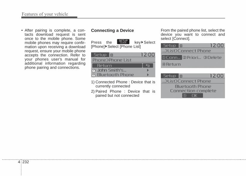
Features of your vehicle
2324
• After pairing is complete, a con-tacts download request is sentonce to the mobile phone. Somemobile phones may require confir-mation upon receiving a downloadrequest, ensure your mobile phoneaccepts the connection. Refer toyour phones user’s manual foradditional information regardingphone pairing and connections.
Connecting a Device
Press the key Select[Phone] Select [Phone List]
1) Connected Phone : Device that iscurrently connected
2) Paired Phone : Device that ispaired but not connected
From the paired phone list, select thedevice you want to connect andselect [Connect].
SETUPCLOCK

4 233
Features of your vehicle
Changing Priority
What is Priority?It is possible to pair up to fiveBluetooth® Wireless Technologydevices with the car audio system.The "Change Priority" feature is usedto set the connection priority ofpaired phones.
Press the key Select[Phone] Select [Phone List]
From the paired phone list, selectthe phone you want to switch to thehighest priority, then select [ChangePriority] button from the Menu. Theselected device will be changed tothe highest priority.
• Priority icon will be displayed whenthe selected phone is set as a pri-ority phone.
SETUPCLOCK

Features of your vehicle
2344
Disconnecting a Device
Press the key Select[Phone] Select [Phone List]
From the paired phone list, select thecurrently connected device andselect [Disconnect] button.
Deleting a Device
Press the key Select[Phone] Select [Phone List]
From the paired phone list, select thedevice you want to delete and select[Delete] button.
• When deleting the currently con-nected device, the device will auto-matically be disconnected to pro-ceed with the deleting process.
• If a paired Bluetooth® WirelessTechnology device is deleted, thedevice’s call history and contactsdata will also be deleted.
• To re-use a deleted device, youmust pair the device again.
SETUPCLOCK
SETUPCLOCK

4 235
Features of your vehicle
USING Bluetooth® WirelessTechnology(if equipped)
Phone Menu Screen
Phone MenusWith a Bluetooth® Wireless Technologydevice connected, press the key to display the Phone menuscreen.
1) Favorite : Up to 20 frequentlyused contacts saved for easyaccess.
2) Call History : Displays the call his-tory list screen
3) Contacts : Displays the Contactslist screen
4) Setup : Displays Phone relatedsettings.
• If you select the [Call History] but-ton but there is no call history data,a prompt is displayed which asks todownload call history data.
• If you select the [Contacts] buttonbut there is no contacts datastored, a prompt is displayed whichasks to download contacts data.
• This feature may not be supportedin some mobile phones. For moreinformation on download support,refer to your mobile phone user’smanual.
Answering Calls
Answering a CallAnswering a call with a Bluetooth®
Wireless Technology device connect-ed will display the following screen.To accept the call, press key onthe steering wheel while the call isincoming.
1) Caller : Displays the other caller'sname when the incoming caller issaved within your contacts
2) Incoming Number : Displays theincoming number
PHONE

Features of your vehicle
2364
• When an incoming call pop-up isdisplayed, most Audio and SETUPmode features are disabled. Onlythe call volume will operate.
• The telephone number may not beproperly displayed in some mobilephones.
• When a call is answered with themobile phone, the call mode willautomatically revert to Privatemode.
Favorites
Press the key Select[Favorites]
1) Saved favorite contact : Connectscall upon selection
2) To add favorite : Downloaded con-tacts be saved as favorite.
• To save Favorite, contacts shouldbe downloaded.
• Contact saved in Favorites will notbe automatically updated if thecontact has been updated in thephone. To update Favorites, deletethe Favorite and create a newFavorite.
Call History
Press the key Select [CallHistory]
A list of incoming, outgoing andmissed calls is displayed.• Call history may not be saved in the
call history list in some mobilephones.
• Calls received with hidden caller IDwill not be saved in the call historylist.
• Calling through the call history is notpossible when there is no call histo-ry stored or a Bluetooth® WirelessTechnology phone is not connected.
• Up to 50 received, dialed andmissed calls are stored in CallHistory.
• Time of received/dialed calls andcall time information are not storedin Call History.
PHONE PHONE
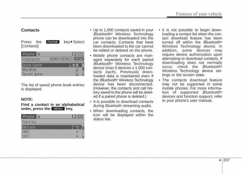
4 237
Features of your vehicle
Contacts
Press the key Select[Contacts]
The list of saved phone book entriesis displayed.
NOTE:Find a contact in an alphabeticalorder, press the key.
• Up to 1,000 contacts saved in yourBluetooth® Wireless Technologyphone can be downloaded into thecar contacts. Contacts that havebeen downloaded to the car cannotbe edited or deleted on the phone.
• Mobile phone contacts are man-aged separately for each pairedBluetooth® Wireless Technologydevice (max 5 devices x 1,000 con-tacts each). Previously down-loaded data is maintained even ifthe Bluetooth® Wireless Technologydevice has been disconnected.(However, the contacts and call his-tory saved to the phone will be delet-ed if a paired phone is deleted.)
• It is possible to download contactsduring Bluetooth streaming audio.
• When downloading contacts, theicon will be displayed within thestatus bar.
• It is not possible to begin down-loading a contact list when the con-tact download feature has beenturned off within the Bluetooth®
Wireless Technology device. Inaddition, some devices mayrequire device authorization uponattempting to download contacts. Ifdownloading does not normallyoccur, check the Bluetooth®
Wireless Technology device set-tings or the screen state.
• The contacts download featuremay not be supported in somemobile phones. For more informa-tion of supported Bluetooth®
devices and function support, referto your phone’s user manual.
MENU
PHONE

Features of your vehicle
2384
Bluetooth® WirelessTechnology Setting
The Bluetooth® word mark and logosare registered trademarks owned byBluetooth SIG, Inc. and any use ofsuch marks by Kia is under license.Other trademarks and trade namesare those of their respective owners.A Bluetooth® enabled cell phone isrequired to use Bluetooth® WirelessTechnology.
Pairing a New DevicePress the key Select[Phone] Select [Pair Phone]
Bluetooth® Wireless Technologydevices can be paired with the audiosystem.For more information, refer to the“Pairing through Phone Setup” sec-tion within Bluetooth® WirelessTechnology.
Viewing Paired Phone ListPress the key Select[Phone] Select [Phone List]
This feature is used to view mobilephones that have been paired withthe audio system. Upon selecting apaired phone, the setup menu is dis-played.For more information, refer to the“Setting Bluetooth® WirelessTechnology Connection” section withinBluetooth® Wireless Technology.
SETUPCLOCK
SETUPCLOCK
WARNINGDriving while distracted canresult in a loss of vehicle controlthat may lead to an accident,severe personal injury, anddeath. The driver’s primaryresponsibility is in the safe andlegal operation of a vehicle, anduse of any handheld devices,other equipment, or vehicle sys-tems which take the driver’seyes, attention and focus awayfrom the safe operation of a vehi-cle or which are not permissibleby law should never be used dur-ing operation of the vehicle.

4 239
Features of your vehicle
1) Connect/Disconnect Phone :Connect/ disconnects currentlyselected phone
2) Change Priority : Sets currentlyselected phone to highest connec-tion priority
3) Delete : Deletes the currentlyselected phone
4) Return : Moves to the previousscreen
• To learn more about whether yourmobile phone supports contactsdownloads, refer to your mobilephone user’s manual.
• The contacts for only the connect-ed phone can be downloaded
Downloading ContactsPress the key Select[Phone] Select [Contacts Download]
As the contacts are downloadedfrom the mobile phone, a downloadprogress bar is displayed.
• Upon downloading phone con-tacts, the previous correspondingdata is deleted.
• This feature may not be supportedin some mobile phones.
• Voice Recognition may not operatewhile contacts are being down-loaded.
Outgoing VolumePress the key Select[Phone] Select [Outgoing Volume]
Use TUNE knob to adjust the out-going volume level.
• While on a call, the volume can bechanged by using the key.
SEEKTRACK
SETUPCLOCK
SETUPCLOCK

Features of your vehicle
2404
Turning Bluetooth System OffPress the key Select[Phone] Select [Bluetooth SystemOff]Once Bluetooth® Wireless Technologyis turned off, Bluetooth® WirelessTechnology related features will notbe supported within the audio sys-tem.
• To turn Bluetooth® WirelessTechnology back on, go to
[Phone] and select “Yes”.SETUP
CLOCK
SETUPCLOCK

4 241
Features of your vehicle
VOICE RECOGNITION
Using Voice Recognition
Starting Voice RecognitionShortly press the key on thesteering wheel. Say a command
If prompt feedback is in [ON], thenthe system will say “Please say acommand after the beep (BEEP)”• If prompt feedback is in [OFF]
mode, then the system will onlysay “(BEEP)”
• To change Prompt Feedback[On]/[Off], go to [System]
[Prompt Feedback]• For proper recognition, say the
command after the voice instruc-tion and beep tone.
Skipping Prompt MessagesWhile prompt message is being stat-ed Shortly press the key on thesteering remote controllerThe prompt message is immediatelyended and the beep tone will sound.After the “beep”, say the voice com-mand.
Re-starting Voice RecognitionWhile system waits for a commandShortly press the key on thesteering remote controllerThe command wait state is immedi-ately ended and the beep ton willsound. After the “beep”, say the voicecommand.
SETUPCLOCK
Features of your vehicle
2424
ENDING VOICERECOGNITION
While Voice Recognition is operatingPress and hold the key on the
steering remote controller
• While using voice command,pressing any steering wheel con-trol or a different key will end voicecommand.
• When the system is waiting for avoice command, say “cancel” or“end” to end voice command.
• When the system is waiting for avoice command, press and holdthe key on the steering wheelto end voice command.
Voice Recognition and PhoneContact Tips:The Kia Voice Recognition Systemmay have difficulty understandingsome accents or uncommonnames. When using VoiceRecognition to place a call, speak ina moderate tone, with clear pronun-ciationTo maximize the use of VoiceRecognition, consider these guide-lines when storing contacts:• Do not store single-name entries
(e.g., “Bob”, “Mom”, etc.). Instead,always use full names (includingfirst and last names) for these con-tacts
• Do not use special characters(e.g., '@', '-', '*', '&', etc.)
• Do not use abbreviations (i.e., use"Lieutenant" instead of "Lt.") oracronyms (i.e., use "CountyFinance Department" instead of"C. F. D."; Be sure to say the nameexactly as it is entered in the con-tacts list
• Do not use acronyms (i.e., use“County Finance Department”instead of “CFD”).
• If a name is not recognized fromthe contact list, change it to a moredescriptive name (e.g., use“Grandpa Joseph” instead of “PaJoe”).

4 243
Features of your vehicle
Illustration on using voice commands
• Starting voice command.Shortly pressing the key (under 0.8 seconds):
• Skipping Prompt MessagesBriefly pressing the key (under 0.8 seconds):
• End voice command.Briefly pressing the key (under 0.8 seconds):
while guidance message is being stated
More Help
Contacts
Cancel
More Help
Please say a command afterthe beep (BEEP)
Please say a...
Contacts.Please say the name of the contact you want to call.
(BEEP)
Please say a command after the beep (BEEP)
Beep Beep.. (end beep)Briefly pressing the key (under 0.8 seconds)
Beep~
More HelpHere are some examples of mode commands.You can say a radio type like 'FM', 'AM', or 'Satellite'.You can also say a media source like 'USB', 'MyMusic', or 'iPod'.Additionally, there are phone commands like"Contacts', 'Call History', or 'Dial Number".You can find more detailed commands in the user'smanual.Please say a command after the beep.
More HelpHere are some examples of mode commands.You can say a radio type like 'FM', 'AM', or 'Satellite'.You can also say a media source like 'USB', 'MyMusic', or 'iPod'.Additionally, there are phone commands like"Contacts', 'Call History', or 'Dial Number".You can find more detailed commands in the user'smanual.Please say a command after the beep.

Features of your vehicle
2444
Voice Command List• Common Commands: These commands can be used in most operations. (However a few commands may not be
available during certain operations)
Command FunctionMore Help Provides guidance on commands that can be
used anywhere in the system.
Help Provides guidance on commands that can beused within the current mode.
Call<Name> Calls <Name> saved in ContactsEx) Call “John Smith”
Call <Name> Calls <Name> to the number that is saved as"Mobile" in Contacts Ex) Call "John Smith" on Mobile
Call <Name> Calls <Name> to the number that is saved as"Office" in Contacts Ex) Call "John Smith" in Office
Call <Name> Calls <Name> to the number that is saved as "Home" in Contacts Ex) Call "John Smith" at Home
Call <Name> Calls <Name> to the number that is saved as "Other" in Contacts Ex) Call "John Smith" on Other
Phone Provides guidance on Phone related com-mands. After saying this command, say“Favorites”,“Call History”, “Contacts” or ”DialNumber” execute corresponding functions.
Favorites Display the Favorite screen.
Call History Displays the Call History screen.
Command FunctionContacts Displays the Contacts screen. After saying
this command, say the name of a contactsaved in the Contacts to automatically con-nect the call.
Dial Number Display the Dial number screen. After sayingthis command, you can say the number thatyou want to call.
Redial Connects the most recently called number.
Tutorial Provide guidance on how to use voice recognition and Bluetooth® connections
• When listening to the radio, displays the nextradio screen. (FM1➟FM2➟AM➟SAT1➟
SAT2➟SAT3➟FM1)
Radio • When listening to a different mode, displaysthe most recently played radio screen.
• When currently listening to the FM radio,maintains the current state.
• When listening to a different mode, displaysthe most recently played FM screen.
FM1(FM One) Displays the FM1 screen.
FM2(FM Two) Displays the FM2 screen.
AM Displays the AM screen.
on Mobile
in Office
at Home
on Other

4 245
Features of your vehicle
Command FunctionFM Preset 1~6 Plays the most recently played broadcast
saved in FM Preset 1~6.
AM Preset 1~6 Plays the broadcast saved in AM Preset 1~6.
FM 87.5~107.9 Plays the FM broadcast of the correspondingfrequency.
AM 530~1710 Plays the AM broadcast of the correspondingfrequency.
SiriusXM® • When currently listening to the SiriusXM®,maintains the current state.
• When listening to a different mode, displaysthe most recently played SiriusXM® screen.
SiriusXM® (Satellite) Displays the selected SiriusXM® screen.
SiriusXM® Channel Plays the selected SiriusXM® channel.
Media Moves to the most recently played mediascreen.
USB Plays USB music.
iPod® Plays iPod® music.
Command FunctionMy Music Plays the music saved in My Music.
AUX (Auxiliary) Plays the connected external device.
Bluetooth® Audio Plays the music saved in connected Bluetooth®
device.
Please repeat Repeats the most recent comment.
Mute Mutes the sound.
Cancel (Exit) Ends voice command.
0~223
1~3
(Satellite)

Features of your vehicle
2464
• FM/AM radio commands: Commands available duringFM, AM radio operation.
• Satellite radio commands: Commands that can beused while listening to Satellite Radio.
Command FunctionPreset 1~6 Plays the broadcast station saved in Preset 1~6.
Scan Scans receivable frequencies from the currentbroadcast and plays for 10 seconds each.
Preset Scan Moves to the next preset from the currentpresent and plays for 10 seconds each.
Information Displays the information of the current broad-cast.(This feature can be used when receivingRBDS broadcasts.)
Command FunctionChannel 0~223 Plays the selected Satellite Radio channel.
Scan Scans receivable channels from the currentbroadcast and plays for 10 seconds each.
Preset 1~6 Plays the broadcast saved in Preset 1~6.
Information Displays the information of the current broad-cast.

4 247
Features of your vehicle
• USB commands: Commands available during USBoperation.
• iPod® Commands: Commands available during iPod®
operation.
Command FunctionRandom Randomly plays the files within the current
folder.
Random Off Cancels random play to play files in sequentialorder.
Repeat Repeats the current file.
Repeat Off Cancels repeat play to play files in sequentialorder.
Information Displays the information screen of the currentfile.
Next Folder Play the first file in the next folder.
Previous Folder Play the first file in the previous folder.
Command FunctionRandom Randomly plays the songs within the current
category.
Random Off Cancels random play to play songs in sequen-tial order.
Repeat Repeats the current song.
Repeat Off Cancels repeat play to play songs in sequen-tial order.
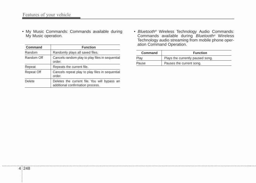
Features of your vehicle
2484
• My Music Commands: Commands available duringMy Music operation.
• Bluetooth® Wireless Technology Audio Commands:Commands available during Bluetooth® WirelessTechnology audio streaming from mobile phone oper-ation Command Operation.
Command FunctionRandom Randomly plays all saved files.
Random Off Cancels random play to play files in sequentialorder.
Repeat Repeats the current file.
Repeat Off Cancels repeat play to play files in sequentialorder.
Delete Deletes the current file. You will bypass anadditional confirmation process.
Command FunctionPlay Plays the currently paused song.
Pause Pauses the current song.

4 249
Features of your vehicle
iPod® is a registered trademark of Apple Inc. iPod®
mobile digital device sold separately. TheBluetooth® word mark and logos are registeredtrademarks owned by Bluetooth SIG, Inc. and anyuse of such marks by Kia is under license.SiriusXM services require a subscription sold sep-arately, or as a package, by Sirius XM Radio Inc. Ifyou decide to continue service after your trial, thesubscription plan you choose will automaticallyrenew thereafter and you will be charged accordingto your chosen payment method at then-currentrates. Fees and taxes apply.To cancel you must callSiriusXM at 1-866-635-2349. See SiriusXMCustomer Agreement for complete terms atwww.siriusxm.com SiriusXM U.S. satellite and dataservices are available only in the 48 contiguousUSA, DC and PR (with coverage limitations).SiriusXM satellite service is also available inCanada; see www.siriusxm.ca All fees and pro-gramming subject to change. Sirius, XM and allrelated marks and logos are trademarks of SiriusXM Radio Inc. Sirius, XM and all related marks andlogos are trademarks of Sirius XM Radio Inc.Android™ is a trademark of Google, Inc. BlackBerryis a registered trademark of Research In MotionLimited (RIM). All other marks, channel names andlogos are the property of their respective owners.All rights reserved.

Features of your vehicle
2504
IC
This device complies with Industry Canada’s licence-exempt RSSs.Operation is subject to the following two conditions:(1) This device may not cause interference; and(2) This device must accept any interference, including interference that may cause undesired operation of the device.
Le présent appareil est conforme aux CNR d'Industrie Canada applicables aux appareils radio exempts de licence.L'exploitation est autorisée aux deux conditions suivantes : (1) l'appareil ne doit pas produire de brouillage, et (2) l'utilisateur de l'appareil doit accepter tout brouillage radioélectrique subi, même si le brouillage est susceptibled'en compromettre le fonctionnement.

Driving your vehicle
• Be sure the exhaust system does not leak . . . . . . . . . . 5-3Before driving . . . . . . . . . . . . . . . . . . . . . . . . . . . . . . 5-4
• Before entering vehicle . . . . . . . . . . . . . . . . . . . . . . . . . 5-4• Necessary inspections . . . . . . . . . . . . . . . . . . . . . . . . . . 5-4• Before starting . . . . . . . . . . . . . . . . . . . . . . . . . . . . . . . 5-5
Key positions. . . . . . . . . . . . . . . . . . . . . . . . . . . . . . . 5-6• Illuminated ignition switch . . . . . . . . . . . . . . . . . . . . . 5-6• Ignition switch position. . . . . . . . . . . . . . . . . . . . . . . . . 5-6• Starting the engine . . . . . . . . . . . . . . . . . . . . . . . . . . . . 5-7
Engine start/stop button . . . . . . . . . . . . . . . . . . . . . 5-9• Illuminated engine start/stop button . . . . . . . . . . . . . . 5-9• Engine start/stop button position. . . . . . . . . . . . . . . . . 5-9• Starting the engine with a smart key . . . . . . . . . . . . 5-11
Manual transaxle . . . . . . . . . . . . . . . . . . . . . . . . . . 5-14• Manual transaxle operation . . . . . . . . . . . . . . . . . . . . 5-14• Good driving practices . . . . . . . . . . . . . . . . . . . . . . . . 5-16
Automatic transaxle . . . . . . . . . . . . . . . . . . . . . . . . 5-17• Automatic transaxle operation. . . . . . . . . . . . . . . . . . 5-17• Good driving practices . . . . . . . . . . . . . . . . . . . . . . . . 5-22
Brake system. . . . . . . . . . . . . . . . . . . . . . . . . . . . . . 5-23• Power brakes . . . . . . . . . . . . . . . . . . . . . . . . . . . . . . . . 5-23• Parking brake - Hand type. . . . . . . . . . . . . . . . . . . . . 5-25• Anti-lock brake system (ABS) . . . . . . . . . . . . . . . . . . 5-27• Electronic stability control (ESC) . . . . . . . . . . . . . . . 5-29
• Vehicle stability management (VSM) . . . . . . . . . . . . 5-33• Hill-start assist control (HAC) . . . . . . . . . . . . . . . . . . 5-34• Good braking practices. . . . . . . . . . . . . . . . . . . . . . . . 5-35
Cruise control system. . . . . . . . . . . . . . . . . . . . . . . 5-37• Cruise control switch . . . . . . . . . . . . . . . . . . . . . . . . . 5-38• To set cruise control speed . . . . . . . . . . . . . . . . . . . . . 5-38• To increase cruise control set speed. . . . . . . . . . . . . . 5-39• To decrease the cruising speed . . . . . . . . . . . . . . . . . . 5-39• To temporarily accelerate with the cruise
control on . . . . . . . . . . . . . . . . . . . . . . . . . . . . . . . . . . 5-39• To cancel cruise control, do one of the following . . . 5-40• To resume cruising speed at more than
approximately 20 mph (30 km/h) . . . . . . . . . . . . . . 5-40• To turn cruise control off, do one of the following. . . 5-41
Active ECO system. . . . . . . . . . . . . . . . . . . . . . . . . 5-42• Active ECO operation. . . . . . . . . . . . . . . . . . . . . . . . . 5-42• When Active ECO is activated. . . . . . . . . . . . . . . . . . 5-42• Limitation of Active ECO operation . . . . . . . . . . . . . 5-42
ISG (Idle Stop and Go) system . . . . . . . . . . . . . . . 5-43• Auto stop . . . . . . . . . . . . . . . . . . . . . . . . . . . . . . . . . . . 5-43• Auto start . . . . . . . . . . . . . . . . . . . . . . . . . . . . . . . . . . . 5-44• Condition of ISG system operation . . . . . . . . . . . . . . 5-45• ISG system deactivation . . . . . . . . . . . . . . . . . . . . . . . 5-46• ISG system malfunction . . . . . . . . . . . . . . . . . . . . . . . 5-47
5

Lane departure warning system (LDWS) . . . . . . 5-48Foward collision warning system (FCWS) . . . . . 5-52Economical operation . . . . . . . . . . . . . . . . . . . . . . 5-56Special driving conditions . . . . . . . . . . . . . . . . . . . 5-58
• Hazardous driving conditions . . . . . . . . . . . . . . . . . 5-58• Reducing the risk of a rollover . . . . . . . . . . . . . . . . . 5-58• Rocking the vehicle . . . . . . . . . . . . . . . . . . . . . . . . . . . 5-59• Smooth cornering . . . . . . . . . . . . . . . . . . . . . . . . . . . . 5-60• Driving at night . . . . . . . . . . . . . . . . . . . . . . . . . . . . . . 5-60• Driving in the rain. . . . . . . . . . . . . . . . . . . . . . . . . . . . 5-61• Driving in flooded areas . . . . . . . . . . . . . . . . . . . . . . . 5-61• Driving off-road . . . . . . . . . . . . . . . . . . . . . . . . . . . . . 5-62• Highway driving . . . . . . . . . . . . . . . . . . . . . . . . . . . . . 5-62
Winter driving . . . . . . . . . . . . . . . . . . . . . . . . . . . . 5-63• Snowy or icy conditions . . . . . . . . . . . . . . . . . . . . . . . 5-63• Use high quality ethylene glycol coolant . . . . . . . . . . 5-64• Check battery and cables . . . . . . . . . . . . . . . . . . . . . . 5-64• Change to "winter weight" oil if necessary . . . . . . . 5-64• Check spark plugs and ignition system. . . . . . . . . . . 5-64• To keep locks from freezing . . . . . . . . . . . . . . . . . . . . 5-64• Use approved window washer anti-freeze in
system . . . . . . . . . . . . . . . . . . . . . . . . . . . . . . . . . . . . . 5-64• Don’t let your parking brake freeze . . . . . . . . . . . . . 5-65• Don't let ice and snow accumulate underneath . . . . 5-65• Carry emergency equipment . . . . . . . . . . . . . . . . . . . 5-65
Trailer Towing . . . . . . . . . . . . . . . . . . . . . . . . . . . . 5-65Vehicle load limit . . . . . . . . . . . . . . . . . . . . . . . . . . 5-66
• Tire and loading information label . . . . . . . . . . . . . . 5-66• Certification label . . . . . . . . . . . . . . . . . . . . . . . . . . . . 5-70
Vehicle weight glossary . . . . . . . . . . . . . . . . . . . . . 5-71• Base curb weight . . . . . . . . . . . . . . . . . . . . . . . . . . . . 5-71• Vehicle curb weight . . . . . . . . . . . . . . . . . . . . . . . . . . . 5-71• Cargo weight . . . . . . . . . . . . . . . . . . . . . . . . . . . . . . . . 5-71• GAW (Gross axle weight) . . . . . . . . . . . . . . . . . . . . . . 5-71• GAWR (Gross axle weight rating) . . . . . . . . . . . . . . . 5-71• GVW (Gross vehicle weight) . . . . . . . . . . . . . . . . . . . 5-71• GVWR (Gross vehicle weight rating) . . . . . . . . . . . . 5-71
5

5 3
Driving your vehicle
E010000AUN-EU
Be sure the exhaust systemdoes not leak.The exhaust system should bechecked whenever the vehicle israised to change the oil or for anyother purpose. If you hear a changein the sound of the exhaust or if youdrive over something that strikes theunderneath side of the vehicle, havethe exhaust system checked as soonas possible by an authorized Kiadealer.
WARNING - Engineexhaust
Do not inhale exhaust fumes orleave your engine running in aenclosed area for a prolongedtime. Exhaust fumes containcarbon monoxide, a colorless,odorless gas that can causeunconsciousness and death byasphyxiation.
WARNING - Open tailgateDo not drive with the tailgateopen. Poisonous exhaust gasescan enter the passenger com-partment If you must drive withthe tailgate open proceed as fol-lows:1. Close all windows.2. Open side vents.3. Set the air intake control at
"Fresh", the air flow control at"Floor" or "Face" and the fanat the highest speed.

Driving your vehicle
45
Before entering vehicle• Be sure that all windows, outside
mirror(s), and outside lights areclean.
• Check the condition of the tires.• Check under the vehicle for any
sign of leaks.• Be sure there are no obstacles
behind you if you intend to back up.
Necessary inspectionsFluid levels, such as engine oil,engine coolant, brake fluid, andwasher fluid should be checked on aregular basis, at the exact intervaldepending on the fluid. Furtherdetails are provided in chapter 7,“Maintenance”.
WARNINGDriving while distracted canresult in a loss of vehicle con-trol, that may lead to an acci-dent, severe personal injury,and death. The driver’s primaryresponsibility is in the safe andlegal operation of a vehicle, anduse of any handheld devices,other equipment, or vehicle sys-tems which take the driver’seyes, attention and focus awayfrom the safe operation of avehicle or which are not permis-sible by law should never beused during operation of thevehicle.
BEFORE DRIVING

5 5
Driving your vehicle
Before starting • Close and lock all doors.• Position the seat so that all con-
trols are easily reached.• Buckle your seat belt.• Adjust the inside and outside
rearview mirrors.• Be sure that all lights work.• Check all gauges.• Check the operation of warning
lights when the ignition switch isturned to the ON position.
• Release the parking brake andmake sure the brake warning lightgoes out.
For safe operation, be sure you arefamiliar with your vehicle and itsequipment.
WARNING - Check surroundings
Always check the surroundingareas near your vehicle for peo-ple, especially children, beforeputting a vehicle into D (Drive)or R (Reverse).
WARNING - Fire riskWhen you intend to park or stopthe vehicle with the engine on,be careful not to depress theaccelerator pedal for a longperiod of time. It may overheatthe engine or exhaust systemand cause fire.
WARNING - Looseobjects
Securely store items in yourvehicle. When you make a sud-den stop or turn the steeringwheel rapidly, loose objectsmay drop on the floor and itcould interfere with the opera-tion of the foot pedals, possiblycausing an accident.
WARNING - Driving whileintoxicated
Do not drive while intoxicated.Drinking and driving is danger-ous. Even a small amount ofalcohol will affect your reflexes,perceptions and judgment.Driving while under the influ-ence of drugs is as dangerousas or more dangerous than driv-ing drunk.

Driving your vehicle
65
Illuminated ignition switch
Whenever a front door is opened, theignition switch will illuminate for yourconvenience, provided the ignitionswitch is not in the ON position. Thelight will go off immediately when theignition switch is turned on. It willalso go off after about 30 secondswhen the door is closed.
Ignition switch positionLOCK
The steering wheel locks to protectagainst theft (if equipped). The igni-tion key can be removed only in theLOCK position.When turning the ignition switch tothe LOCK position, push the keyinward at the ACC position and turnthe key toward the LOCK position.
ACC (Accessory)The steering wheel is unlocked andelectrical accessories are operative.If difficulty is experienced turning theignition switch to the ACC position,turn the key while turning the steer-ing wheel right and left to release thetension.
ONThe warning lights can be checkedbefore the engine is started. This isthe normal running position after theengine is started.Do not leave the ignition switch ON ifthe engine is not running to preventbattery discharge.
KEY POSITIONS (IF EQUIPPED)
OPS053001
OXM059029N

5 7
Driving your vehicle
STARTTurn the ignition switch to the STARTposition to start the engine. Theengine will crank until you releasethe key; then it returns to the ONposition. The brake warning light canbe checked in this position.
The anti-theft steering column lock (ifequipped) is not a substitute for theparking brake. Before leaving the dri-ver’s seat, always make sure the shiftlever is engaged in 1st gear for themanual transaxle or P (Park) forautomatic transaxle, set the parkingbrake fully and shut the engine off.Unexpected and sudden vehiclemovement may occur if these pre-cautions are not taken.
Starting the engine
1.Make sure the parking brake isapplied.
2.Manual Transaxle - Depress theclutch pedal fully and shift thetransaxle into Neutral. Keep theclutch pedal and brake pedaldepressed while turning the igni-tion switch to the start position.Automatic Transaxle - Place thetransaxle shift lever in P (Park).Depress the brake pedal fully.You can also start the engine whenthe shift lever is in the N (Neutral)position.
WARNING - Ignitionswitch
Never turn the ignition switch toLOCK or ACC while the vehicleis moving. This would result inloss of directional control andbraking function, which couldcause an accident.
WARNING - Properfootwear
Always wear appropriate shoeswhen operating your vehicle.Unsuitable shoes (high heels, skiboots, sandals, etc.) may inter-fere with your ability to use thebrake and accelerator pedals.

Driving your vehicle
85
3.Turn the ignition switch to STARTand hold it there until the enginestarts (a maximum of 10 seconds),then release the key.It should be started withoutdepressing the accelerator.
4.Do not wait for the engine to warmup while the vehicle remains sta-tionary.Start driving at moderate enginespeeds. (Steep accelerating anddecelerating should be avoided.)
Do not engage the starter for morethan 10 seconds. If the engine stallsor fails to start, wait 5 to 10 secondsbefore re-engaging the starter.Improper use of the starter maydamage it.
CAUTION - StarterIf the engine stalls while you arein motion, do not attempt tomove the shift lever to the P(Park) position. If traffic androad conditions permit, you mayput the shift lever in the N(Neutral) position while thevehicle is still moving and turnthe ignition switch to the STARTposition in an attempt to restartthe engine.
WARNING - Steeringwheel
Never reach for any controlsthrough the steering wheelwhile the vehicle is in motion.The presence of your hand orarm in this area could cause aloss of vehicle control.

5 9
Driving your vehicle
Illuminated ENGINESTART/STOP button
Whenever the front door is opened,the ENGINE START/STOP buttonwill illuminate for your convenience.The light will go off after about 30seconds when the door is closed.When all entrances are closed, if youlock the vehicle by using the trans-mitter or the smart key, the light willgo off immediately.
ENGINE START/STOP buttonpositionOFF
• With manual transaxle
To turn off the engine (START/RUNposition) or vehicle power (ON posi-tion), stop the vehicle then press theengine start/stop button.
• With automatic transaxle
To turn off the engine (START/RUNposition) or vehicle power (ON posi-tion), press the ENGINESTART/STOP button with the shiftlever in the P (Park) position. Whenyou press the ENGINESTART/STOP button without the shiftlever in the P (Park) position, theENGINE START/STOP button willnot change to the OFF position but tothe ACC position.
In an emergency situation while thevehicle is in motion, you are able toturn the engine off and to the ACCposition by pressing the ENGINESTART/STOP button for more than 2seconds or 3 times successivelywithin 3 seconds. If the vehicle is stillmoving, you can restart the enginewithout depressing the brake pedalby pressing the ENGINESTART/STOP button with the shiftlever in the N (Neutral) position.
ENGINE START/STOP BUTTON (IF EQUIPPED)
OPS053003
Not illuminated

Driving your vehicle
105
ACC(Accessory)
• With manual transaxle
Press the engine start/stop buttonwhen the button is in the OFF posi-tion without depressing the clutchpedal.
• With automatic transaxle
Press the ENGINE START/STOPbutton while it is in the OFF positionwithout depressing the brake pedal.If the ENGINE START/STOP buttonis in the ACC position for more than1 hour, the button is turned off auto-matically to prevent battery dis-charge.
ON
• With manual transaxle
Press the engine start/stop buttonwhen the button is in the ACC posi-tion without depressing the clutchpedal.
• With automatic transaxle
Press the ENGINE START/STOPbutton while it is in the ACC positionwithout depressing the brake pedal.The warning lights can be checkedbefore the engine is started. Do notleave the ENGINE START/STOPbutton in the ON position for a longtime. The battery may discharge,because the engine is not running.
START/RUN
• With manual transaxle
To start the engine, depress theclutch pedal and brake pedal, thenpress the engine start/stop buttonwith the shift lever in the N (Neutral)position.
• With automatic transaxle
To start the engine, depress thebrake pedal and press the ENGINESTART/ STOP button with the shiftlever in the P (Park) or the N(Neutral) position. For your safety,start the engine with the shift lever inthe P (Park) position.
Amber Redish orange Not illuminated

5 11
Driving your vehicle
If you press the ENGINESTART/STOP button withoutdepressing the clutch pedal for man-ual transaxle vehicles or withoutdepressing the brake pedal for auto-matic transaxle vehicles, the enginewill not start and the ENGINESTART/STOP button changes as fol-low:OFF ➔ ACC ➔ ON ➔ OFF or ACC
✽✽ NOTICEIf you leave the ENGINE START/STOP button in the ACC or ONposition for a long time, the batterywill discharge.
Starting the engine with asmart key (if equipped)1.Carry the smart key or leave it
inside the vehicle.2.Make sure the parking brake is
firmly applied3.Manual Transaxle - Depress the
clutch pedal fully and shift thetransaxle into Neutral. Keep theclutch pedal and brake pedaldepressed while starting the engine.Automatic transaxle - Place thetransaxle shift lever in P (Park).Depress the brake pedal fully.You can also start the engine whenthe shift lever is in the N (Neutral)position.
4.Press the ENGINE START/STOPbutton while depressing the brakepedal.It should be started withoutdepressing the accelerator.
5.Do not wait for the engine to warmup while the vehicle remains sta-tionary.Start driving at moderate enginespeeds. (Steep accelerating anddecelerating should be avoided.)
WARNING- Starting vehicle
Never press the ENGINESTART/STOP button while thevehicle is in motion except in anemergency. If the engine stopswhile the vehicle is in motion,this would result in loss ofdirectional control and brakingfunction, which could cause anaccident.
WARNING - Leaving theVehicle
To avoid unexpected or suddenvehicle movement, never leaveyour vehicle if the transmissionis not locked in the P (Park)position and the parking brakeis fully engaged. Before leavingthe driver's seat, always makesure the shift lever is engaged inP (Park), set the parking brakefully and shut the engine off.

Driving your vehicle
125
• Even if the smart key is in the vehi-cle, if it is far away from you, theengine may not start.
• When the ENGINE START/STOPbutton is in the ACC position orabove, if any door is opened, thesystem checks for the smart key. Ifthe smart key is not in the vehicle,a message "key is not in the vehi-cle" will appear on the LCD display.And if all doors are closed, thechime will sound for 5 seconds.The indicator or warning will turnoff while the vehicle is moving.Always have the smart key withyou.
CAUTION - StarterIf the engine stalls while thevehicle is in motion, do notattempt to move the shift leverto the P (Park) position. If thetraffic and road conditions per-mit, you may put the shift leverin the N (Neutral) position whilethe vehicle is still moving andpress the ENGINE START/STOPbutton in an attempt to restartthe engine.
WARNING - Unintendedvehicle movement
Never leave the smart key in thevehicle with children or vehicleoccupants who are unfamiliarwith the vehicle operation.Pushing the ENGINESTART/STOP button while thesmart key is in the vehicle mayresult in unintended engineactivation and/or unintendedvehicle movement.

5 13
Driving your vehicle
• If the battery is weak or the smartkey does not work correctly, youcan start the engine by pressingthe engine start/stop button withthe smart key.The side with the lock buttonshould contact the enginestart/stop button directly.When you press the enginestart/stop button directly with thesmart key, the smart key shouldcontact the button at a right angle.
(Continued)
(Continued)• When the stop lamp fuse is blown,
you can't start the engine normally.Replace the fuse with a new one. Ifit is not possible, you can start theengine by pressing the ENGINESTART/STOP button for 10 sec-onds while it is in the ACC posi-tion. The engine can start withoutdepressing the brake pedal. But foryour safety always depress thebrake pedal before starting theengine.
Do not press the ENGINE START/STOP button for more than 10 sec-onds except when the stop lamp fuseis blown.
OPS053007

Driving your vehicle
145
Manual transaxle operation• The manual transaxle has 6 for-
ward gears.This shift pattern is imprinted onthe shift knob. The transaxle is fullysynchronized in all forward gearsso shifting to either a higher or alower gear is easily accomplished.
• Press the clutch pedal down fullywhile shifting, then release it slow-ly.If your vehicle is equipped with anignition lock switch, the engine willnot start when starting the enginewithout depressing the clutchpedal. (if equipped)
• The gearshift lever must bereturned to the neutral positionbefore shifting into R (Reverse).The ring (1) located immediatelybelow the shift knob must be pulledupward while moving the shift leverto the R (Reverse) position. (ifequipped)
• Make sure the vehicle is complete-ly stopped before shifting into R(Reverse).Never operate the engine with thetachometer (rpm) in the red zone.
MANUAL TRANSAXLE (IF EQUIPPED)
CAUTION - DownshiftingDo not downshift more than 2gears or downshift the gearwhen the engine is running athigh speed (5,000 RPM or high-er). Such a downshifting maydamage the engine.
OJD053058
The ring (1) must be pushed whilemoving the shift lever.
The shift lever can be moved withoutpushing the ring (1).

5 15
Driving your vehicle
• During cold weather, shifting maybe difficult until the transaxle lubri-cant has warmed up. This is nor-mal and not harmful to thetransaxle.
• If you've come to a complete stopand it's hard to shift into 1st or R(Reverse), put the shift lever in N(Neutral) position and release theclutch. Press the clutch pedal backdown, and then shift into 1st or R(Reverse) gear position.
Using the clutchThe clutch should be pressed all theway to the floor before shifting, thenreleased slowly. The clutch pedalshould always be fully released whiledriving. Do not rest your foot on theclutch pedal while driving. This cancause unnecessary wear. Do notpartially engage the clutch to holdthe vehicle on an incline. This causesunnecessary wear. Use the footbrake or parking brake to hold thevehicle on an incline. Do not operatethe clutch pedal rapidly and repeat-edly.CAUTION
• To avoid premature clutchwear and damage, do notdrive with your foot resting onthe clutch pedal. Also, don’tuse the clutch to hold thevehicle stopped on an uphillgrade, while waiting for a traf-fic light, etc.
• Do not use the shift lever as ahandrest during driving, asthis can result in prematurewear of the transaxle shiftforks.
CAUTIONWhen operating the clutchpedal, depress the clutch pedaldown fully. If you don’t depressthe clutch pedal fully, the clutchmay be damaged or noise mayoccur.
WARNING- Incline parking
Before leaving the driver’s seat,always set the parking brake fullyand shut the engine off. Thenmake sure the transaxle is shiftedinto 1st gear when the vehicle isparked on a level or uphill grade,and shifted into R (Reverse) on adownhill grade. Unexpected andsudden vehicle movement canoccur if these precautions are notfollowed in the order identified.

Driving your vehicle
165
DownshiftingWhen you must slow down in heavytraffic or while driving up steep hills,downshift before the engine starts tolabor. Downshifting reduces thechance of stalling and gives betteracceleration when you again need toincrease your speed. When the vehi-cle is traveling down steep hills,downshifting helps maintain safespeed and prolongs brake life.
Good driving practices• Never take the vehicle out of gear
and coast down a hill. This isextremely hazardous. Always leavethe vehicle in gear.
• Don't "ride" the brakes. This cancause them to overheat and mal-function. Instead, when you aredriving down a long hill, slow downand shift to a lower gear. When youdo this, engine braking will helpslow down the vehicle.
• Slow down before shifting to alower gear. This will help avoidover-revving the engine, which cancause damage.
• Slow down when you encountercross winds. This gives you muchbetter control of your vehicle.
• Be sure the vehicle is completelystopped before you attempt to shiftinto reverse. The transaxle can bedamaged if you do not. To shift intoreverse, depress the clutch, movethe shift lever to neutral, then shiftto the reverse position.
• Exercise extreme caution whendriving on a slippery surface. Beespecially careful when braking,accelerating or shifting gears. On aslippery surface, an abrupt changein vehicle speed can cause thedrive wheels to lose traction andthe vehicle to go out of control.
• Always buckle-up! In a collision, anunbelted occupant is significantlymore likely to be seriously injuredor killed than a properly beltedoccupant.
• Avoid high speeds when corneringor turning. High speed corneringand turning increase the risk ofvehicle rollover. Rollover accidentsare violent and unpredictable.
• Never exceed posted speed limits.

5 17
Driving your vehicle
Automatic transaxle operationThe automatic transaxle has 6 for-ward speeds and one reverse speed.The individual speeds are selectedautomatically, depending on theposition of the shift lever.
✽✽ NOTICEThe first few shifts on a new vehicle,if the battery has been disconnected,may be somewhat abrupt. This is anormal condition, and the shiftingsequence will adjust after shifts arecycled a few times by the TCM(Transaxle Control Module) orPCM (Powertrain Control Module).
AUTOMATIC TRANSAXLE (IF EQUIPPED)
OPS053008
++++ ((((UUUUPPPP))))
---- ((((DDDDOOOOWWWWNNNN))))
The shift lever can be shifted freely.
Press the lock release button when shifting.
Depress the brake pedal and the lock release button when shifting.(If the shift lock system is not equipped, it is not necessary to depress the brake pedal.However, it is recommended to depress the brake pedal to avoid inadvertent movementof the vehicle.)

Driving your vehicle
185
For smooth operation, depress thebrake pedal and the lock release but-ton when shifting from N (Neutral) toa forward or reverse gear.
When stopped on an incline, do nothold the vehicle with the enginepower. Use the service brake or theparking brake.
Transaxle rangesThe indicator in the instrument clus-ter displays the shift lever positionwhen the ignition switch is in the ONposition.
P (Park)
Always come to a complete stopbefore shifting into P (Park). Thisposition locks the transaxle and pre-vents the drive wheels from rotating.
Shifting into P (Park) while the vehi-cle is in motion will cause the drivewheels to lock which will cause youto lose control of the vehicle.
CAUTION - TransaxleTo avoid damage to yourtransaxle, do not accelerate theengine in R (Reverse) or any for-ward gear position with thebrakes on.The transaxle may bedamaged if you shift into P(Park) while the vehicle is inmotion.
WARNING - Leaving theVehicle
To avoid unexpected or suddenvehicle movement, never leaveyour vehicle if the transmissionis not locked in the P (Park)position and the parking brakeis fully engaged. Before leavingthe driver's seat, always makesure the shift lever is engaged inP (Park), set the parking brakefully and shut the engine off.

5 19
Driving your vehicle
R (Reverse)
Use this position to drive the vehiclebackward.
N (Neutral)
The wheels and transaxle are notengaged. The vehicle will roll freelyeven on the slightest incline unlessthe parking brake or service brakesare applied.
D (Drive)
This is the normal forward drivingposition. The transaxle will automati-cally shift through a 6-gearsequence, providing the best fueleconomy and power.
For extra power when passing anoth-er vehicle or climbing grades,depress the accelerator fully, atwhich time the transaxle will auto-matically downshift to the next lowergear.
Sports mode
Whether the vehicle is stationary orin motion, sports mode is selected bypushing the shift lever from the D(Drive) position into the manual gate.To return to D (Drive) range opera-tion, push the shift lever back into themain gate.
In sports mode, moving the shiftlever backwards and forwards willallow you to make gearshifts rapidly.In contrast to a manual transaxle, thesports mode allows gearshifts withthe accelerator pedal depressed.
CAUTION - ShiftingAlways come to a complete stopbefore shifting into or out of R(Reverse); you may damage thetransaxle if you shift into R(Reverse) while the vehicle is inmotion, except when “Rockingthe vehicle” explained in thissection.
OPS053009
Sports mode
++++ ((((UUUUPPPP))))
---- ((((DDDDOOOOWWWWNNNN))))

Driving your vehicle
205
Up (+) : Push the lever forward onceto shift up one gear.
Down (-) : Pull the lever backwardsonce to shift down onegear.
• In sports mode, the driver mustexecute upshifts in accordancewith road conditions, taking care tokeep the engine speed below thered zone.
• In sports mode, only the 6 forwardgears can be selected. To reverseor park the vehicle, move the shiftlever to the R (Reverse) or P (Park)position as required.
• In sports mode, downshifts aremade automatically when the vehi-cle slows down. When the vehiclestops, 1st gear is automaticallyselected.
• In sports mode, when the enginerpm approaches the red zone shiftpoints are varied to upshift auto-matically.
(Continued)
(Continued)• To maintain the required levels of
vehicle performance and safety,the system may not execute cer-tain gearshifts when the shift leveris operated.
• When driving on a slippery road,push the shift lever forward into the+(up) position. This causes thetransaxle to shift into the 2nd gearwhich is better for smooth drivingon a slippery road. Push the shiftlever to the -(down) side to shiftback to the 1st gear.
Shift lock systemFor your safety, the automatictransaxle has a shift lock systemwhich prevents shifting the transaxlefrom P (Park) into R (Reverse)unless the brake pedal is depressed.To shift the transaxle from P (Park)into R (Reverse):1.Depress and hold the brake pedal.2.Start the engine or turn the ignition
switch to the ON position.3.Move the shift lever.If the brake pedal is repeatedlydepressed and released with theshift lever in the P (Park) position, achattering noise near the shift levermay be heard. It is a normal condi-tion.

5 21
Driving your vehicle
Shift-lock override
If the shift lever cannot be movedfrom the P (Park) position into R(Reverse) position with the brakepedal depressed, continue depress-ing the brake, then do the following:1.Carefully remove the cap covering
the shift-lock access hole (1).2.Insert a screwdriver into the
access hole and press down onthe screwdriver.
3.Move the shift lever.4.Have your vehicle inspected by an
authorized Kia dealer immediately.
Ignition key interlock system The ignition key cannot be removedunless the shift lever is in the P(Park) position. Even if the ignitionswitch is in the LOCK position, thekey also cannot be removed.If your vehicle is equipped withENGINE START/STOP button, thebutton will not change to the OFFposition unless the shift lever is in theP (Park) position.
WARNING - Shifting frompark
Always fully depress the brakepedal before and while shiftingout of the P (Park) position intoanother position to avoid inad-vertent motion of the vehiclewhich could injure persons inor around the vehicle.
OPS053010

Driving your vehicle
225
Good driving practices• Never move the gear shift lever
from P (Park) to any other positionwith the accelerator pedaldepressed.
• Never move the gear shift lever intoP (Park) when the vehicle is inmotion.
• Slow down before shifting to alower gear. Otherwise, the lowergear may not be engaged.
• Always use the parking brake. Donot depend on placing thetransaxle in P (Park) to keep thevehicle from moving.
• Optimum vehicle performance andeconomy is obtained by smoothlydepressing and releasing theaccelerator pedal.
Moving up a steep grade from astanding startTo move up a steep grade from astanding start, depress the brakepedal, shift the shift lever to D(Drive). Select the appropriate geardepending on load weight and steep-ness of the grade, and release theparking brake. Depress the accelera-tor gradually while releasing theservice brakes.When accelerating from a stop ona steep hill, the vehicle may have atendency to roll backwards.Shifting the shift lever into 2(Second Gear) will help preventthe vehicle from rolling back-wards.

5 23
Driving your vehicle
Power brakesYour vehicle has power-assistedbrakes that adjust automaticallythrough normal usage.In the event that the power-assistedbrakes lose power because of astalled engine or some other reason,you can still stop your vehicle byapplying greater force to the brakepedal than you normally would. Thestopping distance, however, will belonger.When the engine is not running, thereserve brake power is partiallydepleted each time the brake pedalis applied. Do not pump the brakepedal when the power assist hasbeen interrupted.Pump the brake pedal only whennecessary to maintain steering con-trol on slippery surfaces.
Wet brakes may impair the vehicle’sability to safely slow down; the vehi-cle may also pull to one side whenthe brakes are applied. Applying thebrakes lightly will indicate whetherthey have been affected in this way.Always test your brakes in this fash-ion after driving through deep water.To dry the brakes, apply them lightlywhile maintaining a safe forwardspeed until brake performancereturns to normal.
BRAKE SYSTEM
WARNING - Steep hillbraking
Avoid continuous application ofthe brakes when descending along or steep hill by shifting to alower gear. Continuous brakeapplication will cause the brakesto overheat and could result in atemporary loss of braking per-formance.
CAUTION - Brake Pedal Do not drive with your foot rest-ing on the brake pedal. This willcreate abnormally high braketemperatures which can causeexcessive brake lining and padwear.

Driving your vehicle
245
In the event of brake failure If service brakes fail to operate whilethe vehicle is in motion, you canmake an emergency stop with theparking brake. The stopping dis-tance, however, will be much greaterthan normal.
Disc brakes wear indicatorWhen your brake pads are worn andnew pads are required, you will heara high-pitched warning sound fromyour front brakes or rear brakes. Youmay hear this sound come and go orit may occur whenever you depressthe brake pedal.Please remember that some drivingconditions or climates may cause abrake squeal when you first apply (orlightly apply) the brakes. This is nor-mal and does not indicate a problemwith your brakes.Always replace the front or rearbrake pads as pairs.
WARNING - Parking brakeApplying the parking brakewhile the vehicle is moving atnormal speeds can cause asudden loss of control of thevehicle. If you must use theparking brake to stop the vehi-cle, use great caution in apply-ing the brake.
WARNING - Brake wearDo not ignore high pitchedwhining sounds from yourbrakes. If you ignore this audi-ble warning, you will eventuallylose braking performance,which could lead to a seriousaccident.
CAUTION - Parking brakeDriving with the parking brakeapplied will cause excessivebrake pad (or lining) and brakerotor wear.

5 25
Driving your vehicle
Parking brake - Hand typeApplying the parking brake
To engage the parking brake, firstapply the foot brake and then withoutpressing the release button in, pullthe parking brake lever up as far aspossible.In addition it is recommended thatwhen parking the vehicle on a gradi-ent, the shift lever should be posi-tioned in the appropriate low gear onmanual transaxle vehicles or in the P(Park) position for automatictransaxle vehicles.
Releasing the parking brake
To release the parking brake, firstapply the foot brake and pull up theparking brake lever slightly. Secondlypress the release button (1) andlower the parking brake lever (2)while holding the button.
CAUTION- Parking brakeDriving with the parking brakeapplied will cause excessivebrake pad and brake rotor wear.
OPS053011
OPS053012
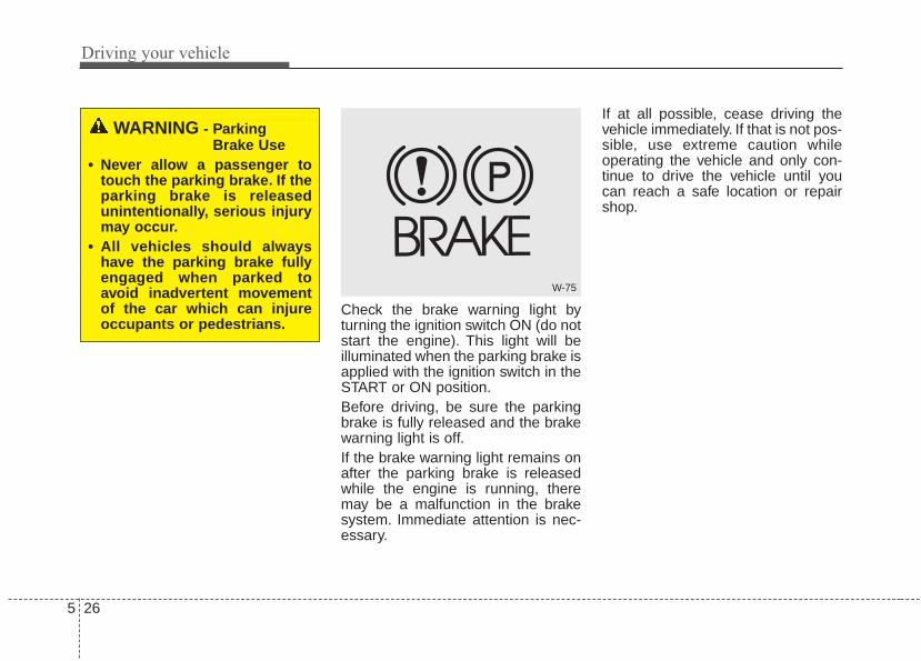
Driving your vehicle
265
Check the brake warning light byturning the ignition switch ON (do notstart the engine). This light will beilluminated when the parking brake isapplied with the ignition switch in theSTART or ON position.Before driving, be sure the parkingbrake is fully released and the brakewarning light is off.If the brake warning light remains onafter the parking brake is releasedwhile the engine is running, theremay be a malfunction in the brakesystem. Immediate attention is nec-essary.
If at all possible, cease driving thevehicle immediately. If that is not pos-sible, use extreme caution whileoperating the vehicle and only con-tinue to drive the vehicle until youcan reach a safe location or repairshop.
W-75
WARNING - ParkingBrake Use
• Never allow a passenger totouch the parking brake. If theparking brake is releasedunintentionally, serious injurymay occur.
• All vehicles should alwayshave the parking brake fullyengaged when parked toavoid inadvertent movementof the car which can injureoccupants or pedestrians.
5 27
Driving your vehicle
Anti-lock brake system (ABS)ABS (or ESC) will not prevent acci-dents due to improper or dangerousdriving maneuvers. Even thoughvehicle control is improved duringemergency braking, always maintaina safe distance between you andobjects ahead. Vehicle speedsshould always be reduced duringextreme road conditions. The vehicleshould be driven at reduced speedsin the following circumstances:• When driving on rough, gravel or
snow-covered roads• When driving with tire chains
installed• When driving on roads where the
road surface is pitted or has differ-ent surface heights.
Driving in these conditions increasethe stopping distance for your vehi-cle.
The ABS continuously senses thespeed of the wheels. If the wheelsare going to lock, the ABS systemrepeatedly modulates the hydraulicbrake pressure to the wheels.When you apply your brakes underconditions which may lock thewheels, you may hear a “tik-tik’’sound from the brakes, or feel a cor-responding sensation in the brakepedal. This is normal and it meansyour ABS is active.In order to obtain the maximum ben-efit from your ABS in an emergencysituation, do not attempt to modulateyour brake pressure and do not try topump your brakes. Press your brakepedal as hard as possible or as hardas the situation allows the ABS tocontrol the force being delivered tothe brakes.
✽✽ NOTICEA click sound may be heard in theengine compartment when the vehi-cle begins to move after the engine isstarted. These conditions are normaland indicate that the anti-lock brakesystem is functioning properly.
• Even with the anti-lock brake sys-tem, your vehicle still requires suf-ficient stopping distance. Alwaysmaintain a safe distance from thevehicle in front of you.
• Always slow down when cornering.The anti-lock brake system cannotprevent accidents resulting fromexcessive speeds.
• On loose or uneven road surfaces,operation of the anti-lock brakesystem may result in a longer stop-ping distance than for vehiclesequipped with a conventionalbrake system.

Driving your vehicle
285
The ABS warning light will stay on forapproximately 3 seconds after theignition switch is ON. During thattime, the ABS will go through self-diagnosis and the light will go off ifeverything is normal. If the light stayson, you may have a problem withyour ABS. Contact an authorized Kiadealer as soon as possible.
• When you drive on a road havingpoor traction, such as an icy road,and have operated your brakescontinuously, the ABS will be activecontinuously and the ABS warninglight may illuminate. Pull your vehi-cle over to a safe place and stopthe engine.
• Restart the engine. If the ABSwarning light goes off, then yourABS system is normal. Otherwise,you may have a problem with theABS. Contact an authorized Kiadealer as soon as possible.
✽✽ NOTICEWhen you jump start your vehiclebecause of a drained battery, theengine may not run as smoothly andthe ABS warning light may turn onat the same time. This happensbecause of low battery voltage. Itdoes not mean your ABS has mal-functioned.• Do not pump your brakes!• Have the battery recharged before
driving the vehicle.W-78

5 29
Driving your vehicle
Electronic stability control(ESC)
The Electronic Stability control(ESC) system is designed to stabi-lize the vehicle during corneringmaneuvers. ESC checks where youare steering and where the vehicle isactually going. ESC applies thebrakes on individual wheels andintervenes with the engine manage-ment system to stabilize the vehicle.Electronic stability control (ESC) willnot prevent accidents. Excessivespeed in turns, abrupt maneuversand hydroplaning on wet surfacescan still result in serious accidents.
Only a safe and attentive driver canprevent accidents by avoiding maneu-vers that cause the vehicle to losetraction. Even with ESC installed,always follow all the normal precau-tions for driving - including driving atsafe speeds for the conditions.The Electronic Stability Control(ESC) system is an electronic sys-tem designed to help the driver main-tain vehicle control under adverseconditions. It is not a substitute forsafe driving practices. Factors includ-ing speed, road conditions and driv-er steering input can all affectwhether ESC will be effective in pre-venting a loss of control. It is still yourresponsibility to drive and corner atreasonable speeds and to leave asufficient margin of safety.When you apply your brakes underconditions which may lock thewheels, you may hear a “tik-tik’’sound from the brakes, or feel a cor-responding sensation in the brakepedal. This is normal and it meansyour ESC is active.
✽✽ NOTICEA click sound may be heard in theengine compartment when the vehi-cle begins to move after the engine isstarted. These conditions are normaland indicate that the ElectronicStability Control System is function-ing properly.
✽✽ NOTICEFor maximum protection, alwayswear your seat belt. No system, nomatter how advanced, can compen-sate for all driver error and/or driv-ing conditions. Always drive respon-sibly.
OPS055013N

Driving your vehicle
305
ESC operationESC ON condition
• When the ignition is turnedON, ESC and ESC OFFindicator lights illuminate forapproximately 3 seconds,then ESC is turned on.
• Press the ESC OFF but-ton for at least half a sec-ond after turning the igni-tion ON to turn ESC off.(ESC OFF indicator willilluminate). To turn theESC on, press the ESCOFF button (ESC OFFindicator light will go off).
• When starting the engine,you may hear a slight tick-ing sound. This is the ESCperforming an automaticsystem self-check and doesnot indicate a problem.
When operating
When the ESC is in opera-tion, the ESC indicator lightblinks.• When the Electronic
Stability Control is operat-ing properly, you can feel aslight pulsation in the vehi-cle. This is only the effectof brake control and indi-cates nothing unusual.
• When moving out of themud or driving on a slip-pery road, pressing theaccelerator pedal may notcause the engine rpm(revolutions per minute) toincrease.
ESC operation offESC OFF state
This car has 2 kinds of ESCoff states.If the engine stops whenESC is off, ESC remains off.Upon restarting the engine,the ESC will automaticallyturn on again.
-

5 31
Driving your vehicle
• ESC off state 1To cancel ESC operation, press theESC OFF button (ESC OFF )shortly (ESC OFF indicator light(ESC OFF ) illuminates). At thisstate, the engine control functiondoes not operate. It means the trac-tion control function does not oper-ate. Brake control function only oper-ates.If your vehicle is equipped with clus-ter type B, a message also willappear on the LCD display.
• ESC off state 2To cancel ESC operation, press theESC OFF button (ESC OFF ) formore than 3 seconds. ESC OFF indi-cator light (ESC OFF ) illuminatesand ESC OFF warning chime willsound. At this state, the engine con-trol function and brake control func-tion do not operate. It means the carstability control function does notoperate any more.If your vehicle is equipped with clus-ter type B, a message also willappear on the LCD display.
Indicator lightWhen ignition switch is turned to ON,the indicator light illuminates, thengoes off if the ESC system is operat-ing normally.The ESC indicator light blinks when-ever ESC is operating or illuminateswhen ESC fails to operate.The ESC OFF indicator light comeson when the ESC is turned off withthe button.
OPS053022 OPS053023
■ ESC indicator light
■ ESC OFF indicator light

Driving your vehicle
325
ESC OFF usageWhen driving
• ESC should be turned on for dailydriving whenever possible.
• To turn ESC off while driving, pressthe ESC OFF button while drivingon a flat road surface.
✽✽ NOTICE• When operating the vehicle on a
dynamometer, ensure that theESC is turned off (ESC OFF lightilluminated). If the ESC is left on,it may prevent the vehicle speedfrom increasing, and result in falsediagnosis.
• Turning the ESC off does notaffect ABS or brake system opera-tion.
CAUTIONDriving with varying tire orwheel sizes may cause the ESCsystem to malfunction. Whenreplacing tires, make sure theyare the same size as your origi-nal tires.
WARNING - OperatingESC
Never press the ESC OFF but-ton while ESC is operating (ESCindicator light blinks).If ESC is turned off while ESC isoperating, the vehicle may slipout of control.
WARNING- Electronic stability control
Drive carefully even thoughyour vehicle has ElectronicStability Control. It can onlyassist you in maintaining con-trol under certain circum-stances.

5 33
Driving your vehicle
Vehicle stability management(VSM)This system provides furtherenhancements to vehicle stabilityand steering responses when a vehi-cle is driving on a slippery road or avehicle detects changes in coeffi-cient of friction between right wheelsand left wheels when braking.
VSM operationWhen the VSM is in operation, ESCindicator light ( ) blinks.When the vehicle stability manage-ment is operating properly, you canfeel a slight pulsation in the vehicleand/or abnormal steering responses(EPS). This is only the effect of brakeand EPS control and indicates noth-ing unusual.
The VSM does not operate when:
• Driving on bank road such as gra-dient or incline
• Driving in reverse• ESC OFF indicator light ( )
remains on the instrument cluster• EPS indicator light remains on the
instrument cluster
VSM operation offIf you press the ESC OFF button toturn off the ESC, the VSM will alsocancel and the ESC OFF indicatorlight ( ) illuminates.To turn on the VSM, press the buttonagain. The ESC OFF indicator lightgoes out.
Malfunction indicatorThe VSM can be deactivated even ifyou don’t cancel the VSM operationby pressing the ESC OFF button. Itindicates that a malfunction hasbeen detected somewhere in theElectric Power Steering system orVSM system. If the ESC indicatorlight ( ) or EPS warning lightremains on, take your vehicle to anauthorized Kia dealer and have thesystem checked.
✽✽ NOTICE• The VSM is designed to function
above approximately 13 mph (22km/h) on curves.
• The VSM is designed to functionabove approximately 6 mph (10km/h) when a vehicle is braking ona split-mu road. The split-mu roadis made of surfaces which have dif-ferent friction forces.

Driving your vehicle
345
• The Vehicle Stability Managementsystem is not a substitute for safedriving practices but a supplemen-tary function only. It is the respon-sibility of the driver to always checkthe speed and the distance to thevehicle ahead. Always hold thesteering wheel firmly while driving.
• Your vehicle is designed to activateaccording to the driver’s intention,even with installed VSM. Alwaysfollow all the normal precautionsfor driving at safe speeds for theconditions – including driving inclement weather and on a slipperyroad.
Hill-start assist control (HAC)A vehicle has the tendency to rollback on a steep hill when it starts togo after stopping. The Hill-startAssist Control (HAC) prevents thevehicle from rolling back by applyingthe brakes automatically for about 2seconds. The brakes are releasedwhen the accelerator pedal isdepressed or after about 2 seconds.The HAC is activated only for about 2seconds, so when the vehicle isstarting off always depress the accel-erator pedal.
WARNING - MaintainingBrake Pressure on Incline
HAC does not replace the needto apply brakes while stoppedon an incline. While stopped,make sure you maintain brakepressure sufficient to preventyour vehicle from rolling back-ward and causing an accident.Don’t release the brake pedaluntil you are ready to accelerateforward.

5 35
Driving your vehicle
Good braking practices• Check to be sure the parking brake
is not engaged and the parkingbrake indicator light is out beforedriving away.
• Driving through water may get thebrakes wet. They can also get wetwhen the vehicle is washed. Wetbrakes can be dangerous! Yourvehicle will not stop as quickly if thebrakes are wet. Wet brakes maycause the vehicle to pull to oneside.To dry the brakes, apply the brakeslightly until the braking actionreturns to normal, taking care tokeep the vehicle under control atall times. If the braking action doesnot return to normal, stop as soonas it is safe to do so and call anauthorized Kia dealer for assis-tance.
• Don't coast down hills with thevehicle out of gear.This is extreme-ly hazardous. Keep the vehicle ingear at all times, use the brakes toslow down, then shift to a lowergear so that engine braking willhelp you maintain a safe speed.
• Don't "ride" the brake pedal.Resting your foot on the brakepedal while driving can be danger-ous because the brakes mightoverheat and lose their effective-ness. It also increases the wear ofthe brake components.
• If a tire goes flat while you are driv-ing, apply the brakes gently andkeep the vehicle pointed straightahead while you slow down. Whenyou are moving slowly enough for itto be safe to do so, pull off the roadand stop in a safe place.
• If your vehicle is equipped with anautomatic transaxle, don't let yourvehicle creep forward. To avoidcreeping forward, keep your footfirmly on the brake pedal when thevehicle is stopped.
• Be cautious when parking on a hill.Firmly engage the parking brakeand place the shift lever in P (auto-matic transaxle) or in first orreverse gear (manual transaxle). Ifyour vehicle is facing downhill, turnthe front wheels into the curb tohelp keep the vehicle from rolling. Ifyour vehicle is facing uphill, turnthe front wheels away from thecurb to help keep the vehicle fromrolling. If there is no curb or if it isrequired by other conditions tokeep the vehicle from rolling, blockthe wheels.

Driving your vehicle
365
• Under some conditions your park-ing brake can freeze in theengaged position. This is most like-ly to happen when there is anaccumulation of snow or icearound or near the rear brakes or ifthe brakes are wet. If there is a riskthat the parking brake may freeze,apply it only temporarily while youput the shift lever in P (automatictransaxle) or in first or reverse gear(manual transaxle) and block therear wheels so the vehicle cannotroll. Then release the parkingbrake.
• Do not hold the vehicle on theupgrade with the acceleratorpedal.This can cause the transaxleto overheat. Always use the brakepedal or parking brake.
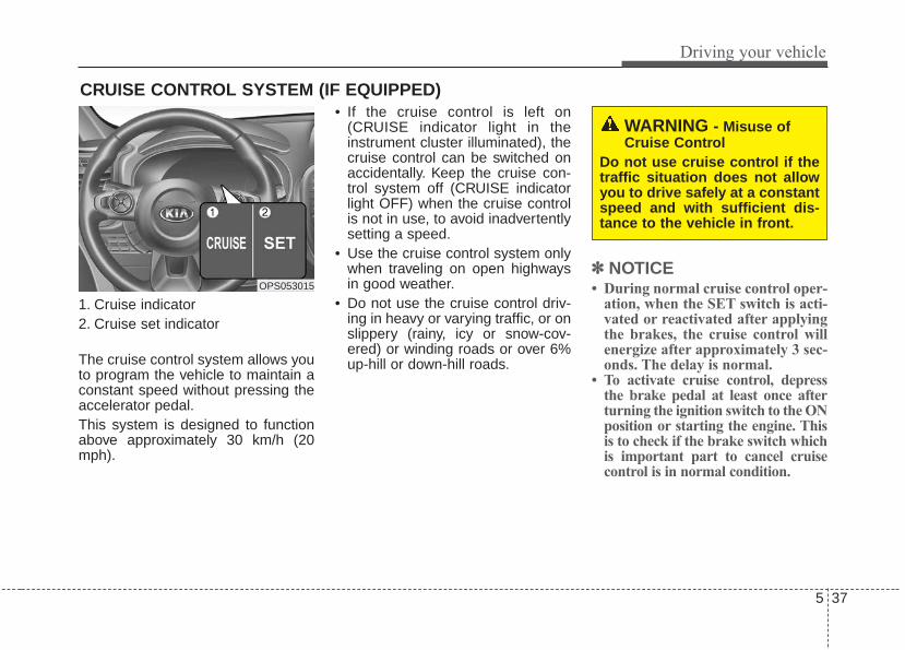
5 37
Driving your vehicle
1. Cruise indicator2. Cruise set indicator
The cruise control system allows youto program the vehicle to maintain aconstant speed without pressing theaccelerator pedal.This system is designed to functionabove approximately 30 km/h (20mph).
• If the cruise control is left on(CRUISE indicator light in theinstrument cluster illuminated), thecruise control can be switched onaccidentally. Keep the cruise con-trol system off (CRUISE indicatorlight OFF) when the cruise controlis not in use, to avoid inadvertentlysetting a speed.
• Use the cruise control system onlywhen traveling on open highwaysin good weather.
• Do not use the cruise control driv-ing in heavy or varying traffic, or onslippery (rainy, icy or snow-cov-ered) or winding roads or over 6%up-hill or down-hill roads.
✽✽ NOTICE• During normal cruise control oper-
ation, when the SET switch is acti-vated or reactivated after applyingthe brakes, the cruise control willenergize after approximately 3 sec-onds. The delay is normal.
• To activate cruise control, depressthe brake pedal at least once afterturning the ignition switch to the ONposition or starting the engine. Thisis to check if the brake switch whichis important part to cancel cruisecontrol is in normal condition.
CRUISE CONTROL SYSTEM (IF EQUIPPED)
OPS053015
WARNING - Misuse ofCruise Control
Do not use cruise control if thetraffic situation does not allowyou to drive safely at a constantspeed and with sufficient dis-tance to the vehicle in front.

Driving your vehicle
385
Cruise control switch
CRUISE : Turns cruise control sys-tem on or off.
CANCEL: Cancels cruise controloperation.
RES+: Resumes or increases cruisecontrol speed.
SET-: Sets or decreases cruise con-trol speed.
To set cruise control speed:
1. Press the CRUISE button on thesteering wheel to turn the systemon. The CRUISE indicator light inthe instrument cluster will illumi-nate.
2. Accelerate to the desired speed,which must be more than 30 km/h(20 mph)
✽✽ NOTICE - Manual transaxleFor manual transaxle vehicles, youshould depress the brake pedal atleast once to set the cruise controlafter starting the engine.
3. Push the SET - switch, andrelease it at the desired speed.The SET indicator light in theinstrument cluster will illuminate.Release the accelerator pedal atthe same time. The desired speedwill automatically be maintained.
On a steep grade, the vehicle mayslow down or speed up slightly whilegoing uphill or downhill.
OPS053018
OPS053016 OPS053017

5 39
Driving your vehicle
To increase cruise control setspeed:
Follow either of these procedures:• Push the RES + switch and hold it.
Your vehicle will accelerate.Release the lever at the speed youwant.
• Push the RES + switch andrelease it immediately.The cruising speed will increase by2km/h (or 1 mph) each time youmove the lever up (to RES+) in thismanner.
To decrease the cruisingspeed:
Follow either of these procedures:• Push the SET - switch and hold it.
Your vehicle will gradually slowdown. Release the lever at thespeed you want to maintain.
• Push the SET - switch and releaseit immediately.The cruising speed will decreaseby 2 km/h (1 mph) each time youmove the lever down (to SET-) inthis manner.
To temporarily accelerate withthe cruise control on:If you want to speed up temporarilywhen the cruise control is on,depress the accelerator pedal.Increased speed will not interferewith cruise control operation orchange the set speed.To return to the set speed, take yourfoot off the accelerator.
OPS053019 OPS053018

Driving your vehicle
405
To cancel cruise control, doone of the following:
• Press the brake pedal.• Depress the clutch pedal if
equipped with a manual transaxle.• Shift into N (Neutral) with an auto-
matic transaxle.• Push the CANCEL switch located
on the steering wheel.• Decrease the vehicle speed lower
than the memory speed by approx-imately 20 km/h (12 mph).
• Decrease the vehicle speed to lessthan approximately 25 km/h (15mph).
Each of these actions will cancelcruise control operation (the SETindicator light in the instrument clus-ter will go off), but it will not turn thesystem off. If you wish to resumecruise control operation, push theRES + switch located on your steer-ing wheel.You will return to your pre-viously preset speed.
To resume cruising speed atmore than approximately 30km/h (20 mph):
If any method other than theCRUISE button was used to cancelcruising speed and the system is stillactivated, the most recent set speedwill automatically resume when theRES+ switch is pushed.It will not resume, however, if thevehicle speed has dropped belowapproximately 30 km/h (20 mph).
OPS053019
OPS053020

5 41
Driving your vehicle
To turn cruise control off, doone of the following:
• Press the CRUISE button (theCRUISE indicator light in theinstrument cluster will go off).
• Turn the ignition off.Both of these actions cancel cruisecontrol operation. If you want toresume cruise control operation,repeat the steps provided in “To setcruise control speed” on the previouspage.
OPS053017
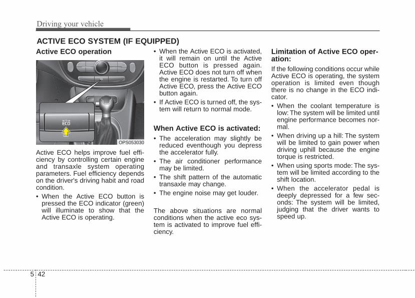
Driving your vehicle
425
Active ECO operation
Active ECO helps improve fuel effi-ciency by controlling certain engineand transaxle system operatingparameters. Fuel efficiency dependson the driver's driving habit and roadcondition.• When the Active ECO button is
pressed the ECO indicator (green)will illuminate to show that theActive ECO is operating.
• When the Active ECO is activated,it will remain on until the ActiveECO button is pressed again.Active ECO does not turn off whenthe engine is restarted. To turn offActive ECO, press the Active ECObutton again.
• If Active ECO is turned off, the sys-tem will return to normal mode.
When Active ECO is activated:• The acceleration may slightly be
reduced eventhough you depressthe accelerator fully.
• The air conditioner performancemay be limited.
• The shift pattern of the automatictransaxle may change.
• The engine noise may get louder.
The above situations are normalconditions when the active eco sys-tem is activated to improve fuel effi-ciency.
Limitation of Active ECO oper-ation:If the following conditions occur whileActive ECO is operating, the systemoperation is limited even thoughthere is no change in the ECO indi-cator.• When the coolant temperature is
low: The system will be limited untilengine performance becomes nor-mal.
• When driving up a hill: The systemwill be limited to gain power whendriving uphill because the enginetorque is restricted.
• When using sports mode: The sys-tem will be limited according to theshift location.
• When the accelerator pedal isdeeply depressed for a few sec-onds: The system will be limited,judging that the driver wants tospeed up.
ACTIVE ECO SYSTEM (IF EQUIPPED)
OPS053030

5 43
Driving your vehicle
Your vehicle may be equipped withthe ISG system, which reduces fuelconsumption by automatically shut-ting down the engine, when the vehi-cle is at a standstill. (For example :red light, stop sign and traffic jam)The engine starts automatically assoon as the starting conditions aremet.The ISG system is ON whenever theengine is running.
✽✽ NOTICEWhen the engine automaticallystarts by the ISG system, somewarning lights (ABS, ESC, ESCOFF, EPS or Parking brake warn-ing light) may turn on for a few sec-onds.This happens because of low batteryvoltage. It does not mean the systemis malfunctioning.
Auto stopTo stop the engine in idle stopmode
Stop the vehicle completely bypressing the brake pedal.
You must reach a speed of at least 5 mph (8 km/h) since last idle stop.The engine will stop and the greenAUTO STOP indicator ( ) on theinstrument cluster will illuminate.
ISG (IDLE STOP AND GO) SYSTEM (IF EQUIPPED)
OPS053028
OPS053029
■ Type A
■ Type B

Driving your vehicle
445
If your vehicle is equipped with clus-ter type B, a message "Auto Stop"also will appear on the LCD display.
If you open the engine hood in autostop mode, the ISG system will deac-tivate (the light on the ISG OFF but-ton will illuminate). A message "AutoStop Deactivated Start Manually" willappear on the LCD display. (ifequipped)Turn the engine on manually.
Auto startTo restart the engine from idlestop mode• Release the brake pedal.
or• Move the shift gear to the R
(Reverse) position or the sportsmode while depressing the brakepedal.
The engine will start and the greenAUTO STOP indicator ( ) on theinstrument cluster will go out.
OPS053014
OPS053024
OTF054124

5 45
Driving your vehicle
The engine will also restart auto-matically without the driver’s anyactions if the following occurs:- When a certain amount of time has
passed with the climate control sys-tem on.
- When the front defroster is on.- The brake vaccum pressure is low.- The battery charging status is low.- The vehicle speed exceeds 1 MPH
(1 km/h).- The fan speed is in the highest
position when the air conditioning ison.
- Engine is turned off by Auto Stopfor a long time.
- If you unfasten the seat belt or openthe driver's door while depressingthe brake pedal.
The green AUTO STOP indicator( ) on the instrument cluster willblink for 5 seconds and a message“Auto Start” will appear on the LCDdisplay (if equipped).
Condition of ISG system oper-ationThe ISG system will operateunder the following condition:- The driver’s seat belt is fastened.- The driver’s door and engine hood
are closed.- The brake vaccum pressure is ade-
quate.- The battery is sufficiently charged.- The outside temperature is more
than -2°C (28.4°F).- The outside temperature is under
32°C (89.6°F).- The engine coolant temperature is
not low.
OPS053025
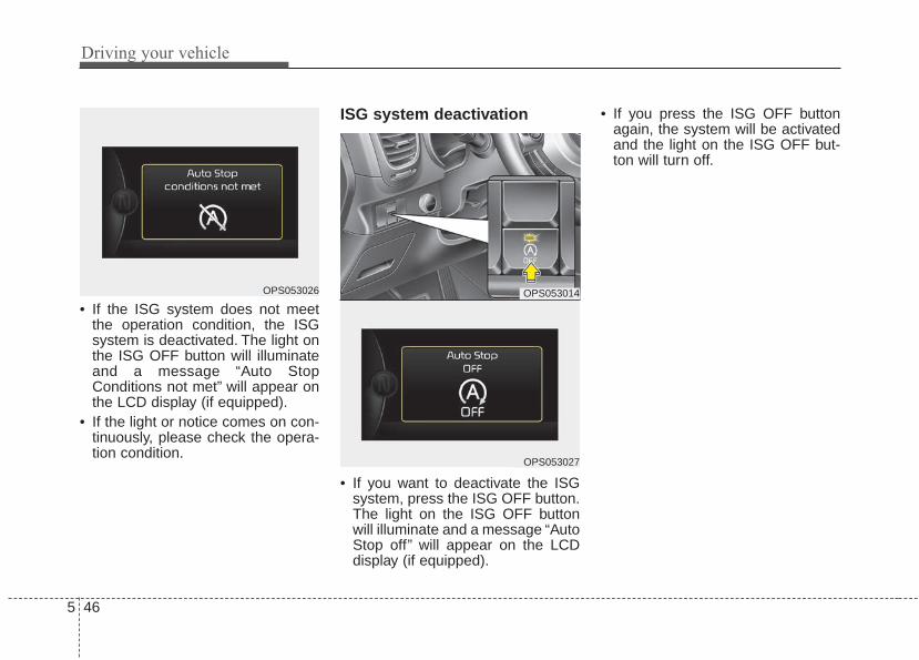
Driving your vehicle
465
• If the ISG system does not meetthe operation condition, the ISGsystem is deactivated. The light onthe ISG OFF button will illuminateand a message “Auto StopConditions not met” will appear onthe LCD display (if equipped).
• If the light or notice comes on con-tinuously, please check the opera-tion condition.
ISG system deactivation
• If you want to deactivate the ISGsystem, press the ISG OFF button.The light on the ISG OFF buttonwill illuminate and a message “AutoStop off” will appear on the LCDdisplay (if equipped).
• If you press the ISG OFF buttonagain, the system will be activatedand the light on the ISG OFF but-ton will turn off.
OPS053026 OPS053014
OPS053027

5 47
Driving your vehicle
ISG system malfunctionThe system may not operatewhen:
- If the ISG related sensors or sys-tem error occurs, the yellow AUTOSTOP indicator ( ) on the instru-ment cluster will stay on after blink-ing for 5 seconds and the light onthe ISG OFF button will illuminate.
• If the ISG OFF button light is notturned off by pressing the ISG OFFbutton again or if the ISG systemcontinuously does not work cor-rectly, please contact an author-ized Kia dealer as soon as possi-ble.
✽✽ NOTICEIf the AGM battery is reconnectedor replaced, ISG function will notoperate immediately.If you want to use the ISG function,the battery sensor needs to be cali-brated for approximately 4 hourswith the ignition off and then, turnthe engine on and off 2 or 3 times.
WARNING - Engine repairTurn the ignition switch to theLOCK (OFF) position or removethe key from the ignition com-pletely before performing workon the vehicle in the enginearea. Failure to do so couldresult in serious injuries due tosudden engine reactivation.
OPS053014
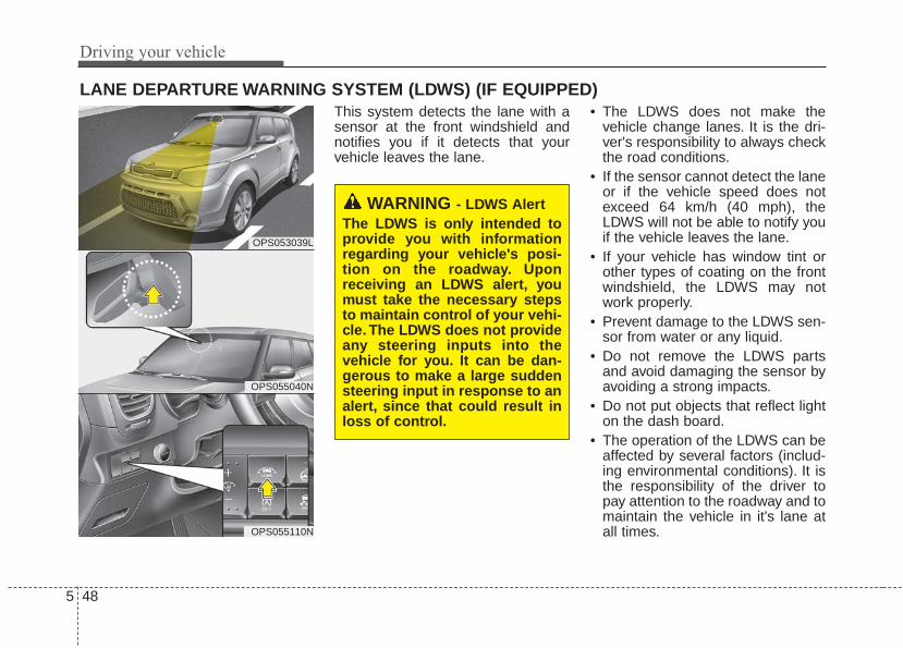
Driving your vehicle
485
This system detects the lane with asensor at the front windshield andnotifies you if it detects that yourvehicle leaves the lane.
• The LDWS does not make thevehicle change lanes. It is the dri-ver's responsibility to always checkthe road conditions.
• If the sensor cannot detect the laneor if the vehicle speed does notexceed 64 km/h (40 mph), theLDWS will not be able to notify youif the vehicle leaves the lane.
• If your vehicle has window tint orother types of coating on the frontwindshield, the LDWS may notwork properly.
• Prevent damage to the LDWS sen-sor from water or any liquid.
• Do not remove the LDWS partsand avoid damaging the sensor byavoiding a strong impacts.
• Do not put objects that reflect lighton the dash board.
• The operation of the LDWS can beaffected by several factors (includ-ing environmental conditions). It isthe responsibility of the driver topay attention to the roadway and tomaintain the vehicle in it's lane atall times.
LANE DEPARTURE WARNING SYSTEM (LDWS) (IF EQUIPPED)
OPS053039L
OPS055040N
OPS055110N
WARNING - LDWS AlertThe LDWS is only intended toprovide you with informationregarding your vehicle's posi-tion on the roadway. Uponreceiving an LDWS alert, youmust take the necessary stepsto maintain control of your vehi-cle. The LDWS does not provideany steering inputs into thevehicle for you. It can be dan-gerous to make a large suddensteering input in response to analert, since that could result inloss of control.

5 49
Driving your vehicle
To operate the LDWS, press the but-ton with the engine start/stop buttonin the ON position. The indicator illu-minates on the cluster. To cancel theLDWS, press the button again.
If the system detects that your vehi-cle is leaving the lane when theLDWS is operating and vehiclespeed exceeds 64 km/h (40 mph),the warning operates as follows:
1.Visual warningIf you leave the lane, the lane youleave on the LCD display blinks yel-low.
2.Auditory warningIf you leave the lane, the warningsound operates.
OPS053042L
OPS053043L
■ When the sensor detects the lane line
■ When the sensor doesn’t detect the lane lineOPS053068
OPS053044L
OPS053045L
■ Left lane departure warning
■ Right lane departure warning

Driving your vehicle
505
The color of symbol will changedepend on the condition of LDWSsystem.- White color : It means the sensor
does not detect thelane line.
- Green color : It means the sensordetects the lane line.
Warning indicator
When the LDWS is not working prop-erly, the warning light will illuminateand the warning message will comeon for a few second.Take your vehicle to an authorizedKia dealer and have the systemchecked.
The LDWS does not operatewhen:• The driver turns on the turn signal
or the hazard warning flasher tochange lane.
• Driving on the lane line.
✽✽ NOTICETo change lanes, operate the turnsignal switch then change the lane.
OPS053068
OPS055111
(Yellow)
WARNING - LDWSLimitations
The Lane Departure WarningSystem is a supplemental sys-tem. Do not solely rely on thesystem but always pay attentionand drive safely.

5 51
Driving your vehicle
The LDWS may not warn youeven if the vehicle leaves thelane, or may warn you even ifthe vehicle does not leave thelane when;• The lane is not visible due to snow,
rain, stain, a puddle or other envi-ronmental conditions.
• The brightness of the outsidechanges suddenly such as tunnelenter/exit.
• The headlights are off at night or ina tunnel.
• The color of the lane marking fromthe road is difficult to distinguish.
• Driving on a steep grade or acurve.
• Light such as street light, sunlightor oncoming vehicle light reflectsfrom water on the road.
• The lens or windshield is stainedwith foreign matter.
• The sensor cannot detect the lanebecause of fog, heavy rain orheavy snow.
• The surrounding of the inside rearview mirror temperature is highdue to a direct ray of light.
• The lane is very wide or narrow.• The lane line is damaged or indis-
tinct.• The windshield is fogged by humid
air in the vehicle.• The shadow is on the lane line by a
median strip.• The sensor cannot distinguish the
lane from the road due to thedust/dirt.
• There is a mark similar to a laneline.
• There is a boundary structure.• The distance from vehicle ahead is
very short or the vehicle aheaddrives hiding the lane line.
• The vehicle vibrates heavily due toroad conditions.
• The lane number increases ordecreases or the lane lines arecrossing.
• Putting something on the dash-board.
• Driving with the sun in front of you.
• Driving in areas under construc-tion.
• The lane line is more than two ineither side (Left/Right)
This device complies withIndustry Canada licence-exemptRSS standard(s).Operation is subject to the followingtwo conditions:(1) This device may not cause inter-
ference, and (2) This device must accept any
interference, including interfer-ence that may cause undesiredoperation of the device.

Driving your vehicle
525
The Foward Collision WarningSystem helps avoid accidents byidentifying critical situations earlyand warning the driver.
FCWS OperationTo operate:
Go to the User Settings Mode(Driving Assist) and select FCW(Forward Collision Warning) on theLCD display.Select [Off] to turn off the system orone of the three warnings timinglevel (Late/Normal/Early) to turn thesystem on and adjust the level of thefor-ward collision warning timing.
The system will turn on and standbyto activate. The system will activatewhen vehicle speed is above 16km/h (10 mph) and below 177 km/h(110 mph ).FCWS will default ON when vehicleis restarted even though FCWS wasturned off on User Settings Mode.
FOWARD COLLISION WARNING SYSTEM (FCWS) (IF EQUIPPED)
OPS055106

5 53
Driving your vehicle
Warning message
A warning message and chime willbe provided when rapidly approach-ing a slower moving, braking orstopped vehicle ahead.Immediately reduce your speed toprevent a collision.
FCWS is a warning system and doesnot apply the brakes automatically ina near crash situation. FCWS maynot provide a warning with enoughtime to help avoid a crash. FCWSdoes not detect pedestrians, ani-mals, signs, construction or otherobjects. It is the responsibility of thedriver to pay attention to the roadwayto prevent collisions.
FCWS malfunction message
When the FCWS is not workingproperly, the warning message willcome on for a few second. After themessage disappears, the masterwarning light will illuminate.
WARNING - ForwardCollision Warning System
The Forward Collision WarningSystem is a supplemental sys-tem to assist you and its effectsmay differ according to road anddriving conditions. Do not solelyrely on the system and alwayspay attention to prevent danger-ous situations from occurring. OYP054118N
OPS055109
■ Warning message
■ Master warning light
OPS055107

Driving your vehicle
545
System disabled
The message will appear when cam-era’s field of view is covered by someobjects. The system stops until thefield of view is normal.
Check the windshield around thecamera view area. If the system doesnot work normally even though cam-era’s field of view is cleared, takeyour vehicle to an authorized Kiadealer and have the systemchecked.
Limitations of the SystemThe Forward Collision WarningSystem may have limits to its abilityto detect distance to the vehicleahead due to road and traffic condi-tions.The FCW could not detect vehicle orcould detect objects as vehicleswhen :- The camera lens is covered with
dirt.- There is heavy rain or heavy snow.- Driving on a curve.- Driving uphill or downhill.- An object ahead is very narrow
such as motorcycles or bicycles.- A vehicle suddenly cut in on your
lane.- The front vehicle suddenly departs
from the lane or it is hidden by otherobjects.
- A vehicle passes by at a higher rateof speed.
OUMA054148
OPS055040N

5 55
Driving your vehicle
- An unusual shape vehicle is aheadsuch as a trailer, special accessvehicles or a truck with uniqueshaped cargo.
- The rear lamps of the vehicleahead is missing, installed on anunusual place or installed unevenly.
- The front vehicle has a separatelamp or LED lamp at the rear of thevehicle.
- Pass through a tunnel where thedifference of intensity of illumina-tion is high.
- Driving with the sun in front of you.- The approaching vehicle turns high
beam on.- The vehicle violently vibrates due to
road conditions.- The vehicle is tilted from a flat tire
or being towed.- The vehicle ahead is not distin-
guishable due to multiple or repeat-ed shape lamps.
- The vehicle ahead is not distin-guishable due to objects that canbe mistaken for a vehicle.
- The surrounding environmentssuch as shadow or markers on aroad, etc. could be mistaken as avehicle.
This device complies withIndustry Canada licence-exemptRSS standard(s).Operation is subject to the followingtwo conditions:(1) This device may not cause inter-
ference, and (2) This device must accept any
interference, including interfer-ence that may cause undesiredoperation of the device.

Driving your vehicle
565
Your vehicle's fuel economy dependsmainly on your style of driving, whereyou drive and when you drive.Each of these factors affects howmany miles (kilometers) you can getfrom a gallon (liter) of fuel.To operateyour vehicle as economically as pos-sible, use the following driving sug-gestions to help save money in bothfuel and repairs:• Drive smoothly. Accelerate at a
moderate rate. Don't make "jack-rabbit" starts or full-throttle shiftsand maintain a steady cruisingspeed. Don't race between stop-lights. Try to adjust your speed tothe traffic so you don't have tochange speeds unnecessarily.Avoid heavy traffic whenever pos-sible. Always maintain a safe dis-tance from other vehicles so youcan avoid unnecessary braking.This also reduces brake wear.
• Drive at a moderate speed. Thefaster you drive, the more fuel yourvehicle uses. Driving at a moderatespeed, especially on the highway,is one of the most effective ways toreduce fuel consumption.
• Don't "ride" the brake or clutchpedal. This can increase fuel con-sumption and also increase wearon these components. In addition,driving with your foot resting on thebrake pedal may cause the brakesto overheat, which reduces theireffectiveness and may lead tomore serious consequences.
• Take care of your tires. Keep theminflated to the recommended pres-sure. Incorrect inflation, either toomuch or too little, results in unnec-essary tire wear. Check the tirepressures at least once a month.
• Be sure that the wheels arealigned correctly. Improper align-ment can result from hitting curbsor driving too fast over irregularsurfaces. Poor alignment causesfaster tire wear and may also resultin other problems as well asgreater fuel consumption.
• Keep your vehicle in good condi-tion. For better fuel economy andreduced maintenance costs, main-tain your vehicle in accordancewith the maintenance schedule insection 7. If you drive your vehiclein severe conditions, more frequentmaintenance is required (see sec-tion 7 for details).
• Keep your vehicle clean. For maxi-mum service, your vehicle shouldbe kept clean and free of corrosivematerials. It is especially importantthat mud, dirt, ice, etc. not beallowed to accumulate on theunderside of the vehicle. This extraweight can result in increased fuelconsumption and also contribute tocorrosion.
• Travel lightly. Don't carry unneces-sary weight in your vehicle. Weightreduces fuel economy.
• Don't let the engine idle longerthan necessary. If you are waiting(and not in traffic), turn off yourengine and restart only whenyou're ready to go.
ECONOMICAL OPERATION

5 57
Driving your vehicle
• Remember, your vehicle does notrequire extended warm-up. Afterthe engine has started, allow theengine to run for 10 to 20 secondsprior to placing the vehicle in gear.In very cold weather, however, giveyour engine a slightly longer warm-up period.
• Don't "lug" or "over-rev" the engine.Lugging is driving too slowly in avery high gear resulting in enginebucking. If this happens, shift to alower gear. Over-revving is racingthe engine beyond its safe limit.This can be avoided by shifting atthe recommended speed.
• Use your air conditioning sparingly.The air conditioning system isoperated by engine power so yourfuel economy is reduced when youuse it.
• Open windows at high speeds canreduce fuel economy.
• Fuel economy is less in crosswindsand headwinds. To help offsetsome of this loss, slow down whendriving in these conditions.
Keeping a vehicle in good operatingcondition is important both for econ-omy and safety. Therefore, have anauthorized Kia dealer performscheduled inspections and mainte-nance.
WARNING - Engine offduring motion
Never turn the engine off tocoast down hills or anytime thevehicle is in motion. The powersteering and power brakes willnot function properly withoutthe engine running. In addition,turning off the ignition whiledriving could engage the steer-ing wheel lock resulting in lossof vehicle steering. Keep theengine on and downshift to anappropriate gear for enginebraking effect.

Driving your vehicle
585
Hazardous driving conditions When hazardous driving conditionsare encountered such as water,snow, ice, mud, sand, or similar haz-ards, follow these suggestions:• Drive cautiously and allow extra
distance for braking.• Avoid sudden braking or steering.• When braking with non-ABS
brakes pump the brake pedal witha light up-and-down motion untilthe vehicle is stopped.
Do not pump the brake pedal on avehicle equipped with ABS.
• If stalled in snow, mud, or sand,use second gear. Accelerate slow-ly to avoid spinning the drivewheels.
• Use sand, rock salt, or other non-slip material under the drivewheels to provide traction whenstalled in ice, snow, or mud.
Reducing the risk of a rolloverThis multi-purpose passenger vehi-cle is defined as a Crossover UtilityVehicle (CUV). CUV’s have higherground clearance and a narrowertrack to make them capable of per-forming in a wide variety of off-roadapplications. Specific design charac-teristics give them a higher center ofgravity than ordinary vehicles. Anadvantage of the higher groundclearance is a better view of theroad, which allows you to anticipateproblems. They are not designed forcornering at the same speeds asconventional passenger vehicles,any more than low-slung sports vehi-cles are designed to perform satis-factorily in off-road conditions. Due tothis risk, driver and passengers arestrongly recommended to buckletheir seat belts. In a rollover crash,an unbelted person is more likely todie than a person wearing a seatbelt.There are steps that a driver canmake to reduce the risk of a rollover.If at all possible, avoid sharp turns orabrupt maneuvers, do not load yourroof rack with heavy cargo, andnever modify your vehicle in any way.
SPECIAL DRIVING CONDITIONS
WARNING - DownshiftingDo not downshift with an auto-matic transaxle while driving onslippery surfaces. The suddenchange in tire speed couldcause the tires to skid andresult in an accident.

5 59
Driving your vehicle
Rocking the vehicle If it is necessary to rock the vehicle tofree it from snow, sand, or mud, firstturn the steering wheel right and leftto clear the area around your frontwheels. Then, shift back and forthbetween 1st (First) and R (Reverse)in vehicles equipped with a manualtransaxle or R (Reverse) and any for-ward gear in vehicles equipped withan automatic transaxle. Do not racethe engine, and spin the wheels as lit-tle as possible. If you are still stuckafter a few tries, have the vehiclepulled out by a tow vehicle to avoidengine overheating and possibledamage to the transaxle.
CAUTION- Vehicle rockingProlonged rocking may causeengine overheating, transaxledamage or failure, and tire dam-age.
WARNING - Replacementtires
Always use the size and type oftires recommended in the tiresection of the manual.Installation of variant tires canaffect the safety and perform-ance of your vehicle. CAUTION- Spinning tires
Do not spin the wheels, espe-cially at speeds more than 56km/h (35 mph). Spinning thewheels at high speeds when thevehicle is stationary couldcause a tire to overheat whichcould result in tire damage thatmay injure bystanders.
WARNING - Sudden vehiclemovement
Do not attempt to rock the vehi-cle if people or objects are near-by. The vehicle may suddenlymove forward or backwards asit becomes unstuck.

Driving your vehicle
605
The ESC system should be turnedOFF prior to rocking the vehicle.
Smooth cornering
Avoid braking or gear changing incorners, especially when roads arewet. Ideally, corners should alwaysbe taken under gentle acceleration. Ifyou follow these suggestions, tirewear will be held to a minimum.
Driving at night
Because night driving presents morehazards than driving in the daylight,here are some important tips toremember:• Slow down and keep more dis-
tance between you and other vehi-cles, as it may be more difficult tosee at night, especially in areaswhere there may not be any streetlights.
OCM053010OUN056051
WARNING- Sudden vehicle movement
Do not attempt to rock the vehi-cle if people or objects are near-by. The vehicle may suddenlymove forward or backwards asit becomes unstuck.

5 61
Driving your vehicle
• Adjust your mirrors to reduce theglare from other driver's head-lights.
• Keep your headlights clean andproperly aimed. (On vehicles notequipped with the automatic head-light aiming feature.) Dirty orimproperly aimed headlights willmake it much more difficult to seeat night.
• Avoid staring directly at the head-lights of oncoming vehicles. Youcould be temporarily blinded, and itwill take several seconds for youreyes to readjust to the darkness.
Driving in the rain
Rain and wet roads can make drivingdangerous, especially if you’re notprepared for the slick pavement.Here are a few things to considerwhen driving in the rain:• A heavy rainfall will make it harder
to see and will increase the dis-tance needed to stop your vehicle,so slow down.
• Keep your windshield wipingequipment in good shape. Replaceyour windshield wiper blades whenthey show signs of streaking ormissing areas on the windshield.
• If your tires are not in good condi-tion, making a quick stop on wetpavement can cause a skid andpossibly lead to an accident. Besure your tires are in good shape.
• Turn on your headlights to make iteasier for others to see you.
• Driving too fast through large pud-dles can affect your brakes. If youmust go through puddles, try todrive through them slowly.
• If you believe you may have gottenyour brakes wet, apply them lightlywhile driving until normal brakingoperation returns.
Driving in flooded areas Avoid driving through flooded areasunless you are sure the water is nohigher than the bottom of the wheelhub. Drive through any water slowly.Allow adequate stopping distancebecause brake performance may beaffected.After driving through water, dry thebrakes by gently applying them sev-eral times while the vehicle is movingslowly.
1VQA3003

Driving your vehicle
625
Driving off-road Drive carefully off-road because yourvehicle may be damaged by rocks orroots of trees. Become familiar withthe off-road conditions where youare going to drive before you begindriving.
Highway drivingTiresAdjust the tire inflation pressures tospecification. Low tire inflation pres-sures will result in overheating andpossible failure of the tires.Avoid using worn or damaged tireswhich may result in reduced tractionor tire failure.Never exceed the maximum tireinflation pressure shown on the tires.
Fuel, engine coolant and engineoilHigh speed travel consumes morefuel than urban motoring. Do not for-get to check both the engine coolantand engine oil.
Drive beltA loose or damaged drive belt mayresult in overheating of the engine.
WARNING - Under/overinflated tires
Always check the tires for properinflation before driving.Underinflated or overinflatedtires can cause poor handling,loss of vehicle control, and sud-den tire failure leading to acci-dents, injuries, and even death.For proper tire pressures, refer to“Tires and wheels” in section 8.
WARNING - Tire treadAlways check the tire treadbefore driving your vehicle.Worn-out tires can result in lossof vehicle control. Worn-out tiresshould be replaced as soon aspossible. For further informationand tread limits, refer to "Tiresand wheels" in section 7.

5 63
Driving your vehicle
Severe weather conditions in thewinter result in greater wear andother problems. To minimize theproblems of winter driving, youshould follow these suggestions:
Snowy or icy conditionsTo drive your vehicle in deep snow, itmay be necessary to use snow tireson your tires. If snow tires are need-ed, it is necessary to select tiresequivalent in size and type of theoriginal equipment tires. Failure to doso may adversely affect the safetyand handling of your vehicle.Furthermore, speeding, rapid accel-eration, sudden brake applications,and sharp turns are potentially veryhazardous practices.During deceleration, use enginebraking to the fullest extent. Suddenbrake applications on snowy or icyroads may cause skids to occur. Youneed to keep sufficient distancebetween the vehicle in operation infront of your vehicle. Also, apply thebrake gently.
Snow tiresIf you mount snow tires on your vehi-cle, make sure they are radial tires ofthe same size and load range as theoriginal tires. Mount snow tires on allfour wheels to balance your vehicle’shandling in all weather conditions.Keep in mind that the traction provid-ed by snow tires on dry roads maynot be as high as your vehicle's orig-inal equipment tires.You should drivecautiously even when the roads areclear. Check with the tire dealer formaximum speed recommendations.Do not install studded tires withoutfirst checking local, state and munic-ipal regulations for possible restric-tions against their use.
WINTER DRIVING
1VQA3005
WARNING - Snow tire sizeSnow tires should be equivalentin size and type to the vehicle'sstandard tires. Otherwise, thesafety and handling of your vehi-cle may be adversely affected.

Driving your vehicle
645
Use high quality ethylene gly-col coolantYour vehicle is delivered with highquality ethylene glycol coolant in thecooling system. It is the only type ofcoolant that should be used becauseit helps prevent corrosion in the cool-ing system, lubricates the waterpump and prevents freezing. Be sureto replace or replenish your coolantin accordance with the maintenanceschedule in section 7. Before winter,have your coolant tested to assurethat its freezing point is sufficient forthe temperatures anticipated duringthe winter.
Check battery and cablesWinter puts additional burdens onthe battery system. Visually inspectthe battery and cables as describedin section 7. The level of charge inyour battery can be checked by anauthorized Kia dealer or a servicestation.
Change to "winter weight" oilif necessaryIn some climates it is recommendedthat a lower viscosity "winter weight"oil be used during cold weather. Seesection 8 for recommendations. Ifyou aren't sure what weight oil youshould use, consult an authorizedKia dealer.
Check spark plugs and igni-tion systemInspect your spark plugs asdescribed in section 7 and replacethem if necessary. Also check allignition wiring and components to besure they are not cracked, worn ordamaged in any way.
To keep locks from freezingTo keep the locks from freezing,squirt an approved de-icer fluid orglycerine into the key opening. If alock is covered with ice, squirt it withan approved de-icing fluid to removethe ice. If the lock is frozen internally,you may be able to thaw it out byusing a heated key. Handle the heat-ed key with care to avoid injury.
Use approved window washeranti-freeze in systemTo keep the water in the windowwasher system from freezing, add anapproved window washer anti-freezesolution in accordance with instruc-tions on the container. Window wash-er anti-freeze is available from anauthorized Kia dealer and most autoparts outlets. Do not use enginecoolant or other types of anti-freezeas these may damage the paint finish.

5 65
Driving your vehicle
Don’t let your parking brakefreezeUnder some conditions your parkingbrake can freeze in the engaged posi-tion. This is most likely to happenwhen there is an accumulation ofsnow or ice around or near the rearbrakes or if the brakes are wet. If thereis a risk the parking brake may freeze,apply it only temporarily while you putthe gear shift lever in P (Park, auto-matic transaxle) or in first or reversegear (manual transaxle) and block therear wheels so the vehicle cannot roll.Then release the parking brake.
Don't let ice and snow accu-mulate underneathUnder some conditions, snow andice can build up under the fendersand interfere with the steering. Whendriving in severe winter conditionswhere this may happen, you shouldperiodically check underneath thevehicle to be sure the movement ofthe front wheels and the steeringcomponents are not obstructed.
Carry emergency equipmentDepending on the severity of theweather, you should carry appropri-ate emergency equipment. Some ofthe items you may want to carryinclude tow straps or chains, flash-light, emergency flares, sand, shov-el, jumper cables, window scraper,gloves, ground cloth, coveralls, blan-ket, etc.
We do not recommend using thisvehicle for trailer towing.
TRAILER TOWING

Driving your vehicle
665
VEHICLE LOAD LIMIT
The label located on the driver's door sill gives the original tire size, cold tire pressures recom-mended for your vehicle, the number of people that can be in your vehicle and vehicle capacityweight.
Tire and loading information label
OPS053100N/OPS053104N/OPS053102N/OPS053101N/OPS053103N/OPS053105N

5 67
Driving your vehicle
Vehicle capacity weight:375 kg (827 lbs.)
Vehicle capacity weight is the maxi-mum combined weight of occupantsand cargo. If your vehicle is equippedwith a trailer, the combined weightincludes the tongue load.
Seating capacity:Total - 5 persons
(Front seat : 2 persons, Rear seat : 3 persons)
Seating capacity is the maximumnumber of occupants including adriver, your vehicle may carry.However, the seating capacity maybe reduced based upon the weight ofall of the occupants, and the weightof the cargo being carried or towed.Do not overload the vehicle as thereis a limit to the total weight, or loadlimit including occupants and cargo,the vehicle can carry.
Towing capacity:We do not recommend using this
vehicle for trailer towing.

Driving your vehicle
685
Cargo capacity:The cargo capacity of your vehiclewill increase or decrease dependingon the weight and the number ofoccupants and the tongue load, ifyour vehicle is equipped with a trailer.
Steps for determining correctload limit1.Locate the statement "The com-
bined weight of occupants andcargo should never exceed XXX kgor XXX lbs.'' on your vehicle's plac-ard.
2.Determine the combined weight ofthe driver and passengers that willbe riding in your vehicle.
3.Subtract the combined weight ofthe driver and passengers fromXXX kg or XXX lbs.
4.The resulting figure equals theavailable amount of cargo and lug-gage load capacity. For example, ifthe "XXX" amount equals 635 kg(1400 lbs.) and there will be five 68kg (150 lbs.) passengers in yourvehicle, the amount of availablecargo and luggage load capacity is295 kg (650 lbs).(635-340 (5 x 68) = 295 kg or1400-750 (5 x 150) = 650 lbs.)
5.Determine the combined weight ofluggage and cargo being loadedon the vehicle. That weight may notsafely exceed the available cargoand luggage load capacity calcu-lated in Step 4.
6.If your vehicle will be towing a trail-er, load from your trailer will betransferred to your vehicle. Consultthis manual to determine how thisreduces the available cargo andluggage load capacity of your vehi-cle.

5 69
Driving your vehicle
Refer to your vehicle’s tire and loading information label for specific information about your vehicle's capacity weightand seating positions. The combined weight of the driver, passengers and cargo should never exceed your vehicle'scapacity weight.
C190F01JM
Item Description Total
AVehicle Capacity 635 kg
Weight (1400 lbs)Subtract Occupant
B Weight 136 kg
68 kg (150 lbs) × 2(300 lbs)
CAvailable Cargo and 499 kg
Luggage weight (1100 lbs)
Example 1
A B C
C190F02JM
Item Description Total
AVehicle Capacity 635 kg
Weight (1400 lbs)Subtract Occupant
B Weight 340 kg
68 kg (150 lbs) × 5(750 lbs)
CAvailable Cargo and 295 kg
Luggage weight (650 lbs)
A B C
Example 2
C190F03JM
Item Description Total
AVehicle Capacity 635 kg
Weight (1400 lbs)Subtract Occupant
B Weight 390 kg
78 kg (172 lbs) × 5(860 lbs)
CAvailable Cargo and 245 kg
Luggage weight (540 lbs)
A B C
Example 3
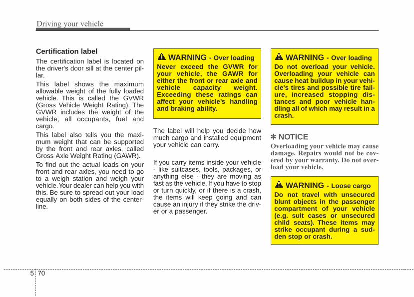
Driving your vehicle
705
Certification labelThe certification label is located onthe driver's door sill at the center pil-lar.This label shows the maximumallowable weight of the fully loadedvehicle. This is called the GVWR(Gross Vehicle Weight Rating). TheGVWR includes the weight of thevehicle, all occupants, fuel andcargo.This label also tells you the maxi-mum weight that can be supportedby the front and rear axles, calledGross Axle Weight Rating (GAWR).To find out the actual loads on yourfront and rear axles, you need to goto a weigh station and weigh yourvehicle.Your dealer can help you withthis. Be sure to spread out your loadequally on both sides of the center-line.
The label will help you decide howmuch cargo and installed equipmentyour vehicle can carry.
If you carry items inside your vehicle- like suitcases, tools, packages, oranything else - they are moving asfast as the vehicle. If you have to stopor turn quickly, or if there is a crash,the items will keep going and cancause an injury if they strike the driv-er or a passenger.
✽✽ NOTICEOverloading your vehicle may causedamage. Repairs would not be cov-ered by your warranty. Do not over-load your vehicle.
WARNING - Over loadingDo not overload your vehicle.Overloading your vehicle cancause heat buildup in your vehi-cle's tires and possible tire fail-ure, increased stopping dis-tances and poor vehicle han-dling all of which may result in acrash.
WARNING - Over loadingNever exceed the GVWR foryour vehicle, the GAWR foreither the front or rear axle andvehicle capacity weight.Exceeding these ratings canaffect your vehicle’s handlingand braking ability.
WARNING - Loose cargoDo not travel with unsecuredblunt objects in the passengercompartment of your vehicle(e.g. suit cases or unsecuredchild seats). These items maystrike occupant during a sud-den stop or crash.

5 71
Driving your vehicle
This section will guide you in theproper loading of your vehicle and/ortrailer, to keep your loaded vehicleweight within its design rating capa-bility, with or without a trailer.Properly loading your vehicle willprovide maximum return of the vehi-cle design performance. Before load-ing your vehicle, familiarize yourselfwith the following terms for determin-ing your vehicle's weight ratings, withor without a trailer, from the vehicle'sspecifications and the certificationlabel:
Base curb weight This is the weight of the vehicleincluding a full tank of fuel and allstandard equipment. It does notinclude passengers, cargo, or option-al equipment.
Vehicle curb weightThis is the weight of your new vehiclewhen you picked it up from your deal-er plus any aftermarket equipment.
Cargo weightThis figure includes all weight addedto the Base Curb Weight, includingcargo and optional equipment.
GAW (Gross axle weight)This is the total weight placed oneach axle (front and rear) - includingvehicle curb weight and all payload.
GAWR (Gross axle weight rating)This is the maximum allowableweight that can be carried by a singleaxle (front or rear). These numbersare shown on the certification label.The total load on each axle mustnever exceed its GAWR.
GVW (Gross vehicle weight)This is the Base Curb Weight plusactual Cargo Weight plus passen-gers.
GVWR (Gross vehicle weight rating)This is the maximum allowableweight of the fully loaded vehicle(including all options, equipment,passengers and cargo). The GVWRis shown on the certification labellocated on the driver’s door sill.
VEHICLE WEIGHT GLOSSARY

What to do in an emergency
Road warning . . . . . . . . . . . . . . . . . . . . . . . . . . . . . . 6-2• Hazard warning flasher . . . . . . . . . . . . . . . . . . . . . . . . 6-2
In case of an emergency while driving. . . . . . . . . . 6-3• If the engine stalls at a crossroad or crossing. . . . . . . 6-3• If you have a flat tire while driving . . . . . . . . . . . . . . . 6-3• If the engine stalls while driving . . . . . . . . . . . . . . . . . 6-3
If the engine will not start . . . . . . . . . . . . . . . . . . . . 6-4• If engine doesn’t turn over or turns over slowly . . . . 6-4• If engine turns over normally but does not start . . . . 6-4
Emergency starting . . . . . . . . . . . . . . . . . . . . . . . . . 6-5• Jump starting. . . . . . . . . . . . . . . . . . . . . . . . . . . . . . . . . 6-5• Push-starting . . . . . . . . . . . . . . . . . . . . . . . . . . . . . . . . . 6-7
If the engine overheats . . . . . . . . . . . . . . . . . . . . . . . 6-8If you have a flat tire (with Spare Tire) . . . . . . . . . 6-9
• Jack and tools . . . . . . . . . . . . . . . . . . . . . . . . . . . . . . . . 6-9• Removing and storing the spare tire . . . . . . . . . . . . . 6-10• Changing tires . . . . . . . . . . . . . . . . . . . . . . . . . . . . . . . 6-10• Use of temporary compact spare tire . . . . . . . . . . . . 6-15• Jack label . . . . . . . . . . . . . . . . . . . . . . . . . . . . . . . . . . . 6-17
If you have a flat tire (with Tire Mobility Kit) . . 6-18• Introduction . . . . . . . . . . . . . . . . . . . . . . . . . . . . . . . . . 6-18• Components of the Tire Mobility Kit . . . . . . . . . . . . 6-20• Using the Tire Mobility Kit . . . . . . . . . . . . . . . . . . . . 6-21• Distributing the sealant. . . . . . . . . . . . . . . . . . . . . . . . 6-22• Checking the tire inflation pressure . . . . . . . . . . . . . 6-23• Notes on the safe use of the Tire Mobility Kit . . . . . 6-23• Technical Data . . . . . . . . . . . . . . . . . . . . . . . . . . . . . . . 6-24
Towing . . . . . . . . . . . . . . . . . . . . . . . . . . . . . . . . . . . 6-25• Towing service . . . . . . . . . . . . . . . . . . . . . . . . . . . . . . . 6-25• Removable towing hook (front) . . . . . . . . . . . . . . . . . 6-26• Emergency towing . . . . . . . . . . . . . . . . . . . . . . . . . . . . 6-27
6

What to do in an emergency
26
ROAD WARNING Hazard warning flasher
The hazard warning flasher servesas a warning to other drivers to exer-cise extreme caution whenapproaching, overtaking, or passingyour vehicle.It should be used whenever emer-gency repairs are being made orwhen the vehicle is stopped near theedge of a roadway.
Depress the flasher switch with theignition switch in any position. Theflasher switch is located in the centerconsole switch panel. All turn signallights will flash simultaneously.
• The hazard warning flasher oper-ates whether your vehicle is run-ning or not.
• The turn signals do not work whenthe hazard flasher is on.
• Care must be taken when usingthe hazard warning flasher whilethe vehicle is being towed.
OPS063001

6 3
What to do in an emergency
If the engine stalls at a cross-road or crossingIf the engine stalls at a crossroad orcrossing, set the shift lever in the N(Neutral) position and then push thevehicle to a safe place.
If you have a flat tire whiledrivingIf a tire goes flat while you are driv-ing:1.Take your foot off the accelerator
pedal and let the vehicle slowdown while driving straight ahead.Do not apply the brakes immedi-ately or attempt to pull off the roadas this may cause a loss of control.When the vehicle has slowed tosuch a speed that it is safe to doso, brake carefully and pull off theroad. Drive off the road as far aspossible and park on a firm levelground. If you are on a dividedhighway, do not park in the medianarea between the two traffic lanes.
2.When the vehicle is stopped, turnon your emergency hazard flash-ers, set the parking brake and putthe transaxle in P (Park, automatictransaxle) or reverse (manualtransaxle).
3.Have all passengers get out of thevehicle. Be sure they all get out onthe side of the vehicle that is awayfrom traffic.
4.When changing a flat tire, followthe instruction provided later in thissection.
If the engine stalls while driv-ing1.Reduce your speed gradually,
keeping a straight line. Move cau-tiously off the road to a safe place.
2.Turn on your emergency flashers.3.Try to start the engine again. If your
vehicle will not start, contact anauthorized Kia dealer or seek otherqualified assistance.
✽✽ NOTICEIf there was a check engine light andloss of power or stall and if safe to doso to wait at least 10 seconds torestart the vehicle after it stalls. Thismay reset the car so it will no longerrun at low power (limp home) condi-tion.
IN CASE OF AN EMERGENCY WHILE DRIVING

What to do in an emergency
46
IF THE ENGINE WILL NOT STARTIf engine doesn't turn over orturns over slowly1.If your vehicle has an automatic
transaxle, be sure the shift lever isin N (Neutral) or P (Park) and theemergency brake is set.
2.Check the battery connections tobe sure they are clean and tight.
3.Turn on the interior light. If the lightdims or goes out when you operatethe starter, the battery is dis-charged.
4.Check the starter connections tobe sure they are securely tight-ened.
5.Do not push or pull the vehicle tostart it. See instructions for "Jumpstarting".
If engine turns over normallybut does not start1.Check the fuel level.2.With the ignition switch in the
LOCK position, check all connec-tors at the ignition coils and sparkplugs. Reconnect any that may bedisconnected or loose.
3.Check the fuel line in the enginecompartment.
4.If the engine still does not start, callan authorized Kia dealer or seekother qualified assistance.
WARNING - Push/pullstart
Do not push or pull the vehicleto start it. Push or pull startingmay cause the catalytic con-verter to overload and create afire hazard.

6 5
What to do in an emergency
EMERGENCY STARTING
Connect cables in numerical orderand disconnect in reverse order.
Jump starting Jump starting can be dangerous ifdone incorrectly. Therefore, to avoidharm to yourself or damage to yourvehicle or battery, follow these jumpstarting procedures. If in doubt, westrongly recommend that you have acompetent technician or towing serv-ice jump start your vehicle.
CAUTION- 12 volt batteryUse only a 12-volt jumper sys-tem. You can damage a 12-voltstarting motor, ignition system,and other electrical partsbeyond repair by use of a 24-volt power supply (either two12-volt batteries in series or a24-volt motor generator set).
WARNING - BatteryNever attempt to check the elec-trolyte level of the battery asthis may cause the battery torupture or explode causing seri-ous injury.
1VQA4001
Dischargedbattery
Jumper Cables
Boosterbattery
(-)
(+)
(+)(-)
WARNING - Frozen batteries
Do not attempt to jump start thevehicle if the discharged batteryis frozen or if the electrolytelevel is low as the battery mayrupture or explode.

What to do in an emergency
66
Jump starting procedure 1.Make sure the booster battery is
12-volt and that its negative termi-nal is grounded.
2.If the booster battery is in anothervehicle, do not allow the vehicles tocome in contact.
3.Turn off all unnecessary electricalloads.
4.Connect the jumper cables in theexact sequence shown in the illus-tration. First connect one end of ajumper cable to the positive termi-nal of the discharged battery (1),then connect the other end to thepositive terminal of the boosterbattery (2).Proceed to connect one end of theother jumper cable to the negativeterminal of the booster battery (3),then the other end to a solid, sta-tionary, metallic point (for example,the engine lifting bracket) awayfrom the battery (4). Do not con-nect it to or near any part thatmoves when the engine is cranked.
Do not allow the jumper cables tocontact anything except the correctbattery terminals or the correctground. Do not lean over the bat-tery when making connections.
5.Start the engine of the vehicle withthe booster battery and let it run at2,000 rpm, then start the engine ofthe vehicle with the dischargedbattery.
If the cause of your battery discharg-ing is not apparent, you should haveyour vehicle checked by an author-ized Kia dealer.
WARNING - BatteryKeep all flames or sparks awayfrom the battery. The batteryproduces hydrogen gas whichwill explode if exposed to flameor sparks.
WARNING - Sulfuric acidrisk
When jump starting your vehi-cle be careful not to get acid onyourself, your clothing or on thevehicle. Automobile batteriescontain sulfuric acid. This ispoisonous and highly corro-sive.
WARNING - Batterycables
Do not connect the jumpercable from the negative terminalof the booster battery to thenegative terminal of the dis-charged battery. This can causethe discharged battery to over-heat and crack, releasing bat-tery acid.

6 7
What to do in an emergency
Push-starting Vehicles equipped with automatictransaxle lock system cannot bepush-started.Follow the directions in this sectionfor jump-starting.
WARNING- Tow startingvehicle
Never tow a vehicle to start itbecause the sudden surge for-ward when the engine startscould cause a collision with thetow vehicle.

What to do in an emergency
86
IF THE ENGINE OVERHEATSIf your temperature gauge indicatesoverheating, you experience a lossof power, or hear loud pinging orknocking, the engine will probably betoo hot. If this happens, you should:
1.Pull off the road and stop as soonas it is safe to do so.
2.Place the shift lever in P (Park,automatic transaxle) or Neutral(manual transaxle) and set theparking brake. If the air condition-ing is on, turn it off.
3.If engine coolant is running outunder the vehicle or steam is com-ing out from underneath the hood,stop the engine. Do not open thehood until the coolant has stoppedrunning or the steaming hasstopped. If there is no visible lossof engine coolant and no steam,leave the engine running andcheck to be sure the engine cool-ing fan is operating. If the fan is notrunning, turn the engine off.
4.Check to see if the water pumpdrive belt is missing. If it is notmissing, check to see that it istight. If the drive belt seems to besatisfactory, check for coolant leak-ing from the radiator, hoses orunder the vehicle. (If the air condi-tioning had been in use, it is nor-mal for cold water to be drainingfrom it when you stop).
5.If the water pump drive belt is bro-ken or engine coolant is leakingout, stop the engine immediatelyand call the nearest authorized Kiadealer for assistance.
6.If you cannot find the cause of theoverheating, wait until the enginetemperature has returned to nor-mal. Then, if coolant has been lost,carefully add coolant to the reser-voir to bring the fluid level in thereservoir up to the halfway mark.
7.Proceed with caution, keepingalert for further signs of overheat-ing. If overheating happens again,call an authorized Kia dealer forassistance.
Serious loss of coolant indicatesthere is a leak in the cooling systemand this should be checked as soonas possible by an authorized Kiadealer.
WARNING - Uncler thehood
While the engine is running,keep hair, hands and clothingaway from moving parts suchas the fan and drive belts to pre-vent injury.
WARNING- Radiator capDo not remove the radiator capwhen the engine is hot. Thismay result in coolant beingblown out of the opening andcause serious burns.

6 9
What to do in an emergency
IF YOU HAVE A FLAT TIREJack and tools (if equipped)
The jack, jack handle, wheel lug nutwrench are stored in the luggagecompartment.Pull up the luggage box cover toreach this equipment.(1) Jack handle(2) Jack(3) Wheel lug nut wrench
Jacking instructions The jack is provided for emergencytire changing only.To prevent the jack from “rattling”while the vehicle is in motion, store itproperly.Follow jacking instructions to reducethe possibility of personal injury.
• Always move the vehicle complete-ly off the road and onto the shoul-der before trying to change a tire.The jack should be used on a firmlevel ground. If you cannot find afirm, level place off the road, call atowing service company for assis-tance.
• Be sure to use the correct front andrear jacking positions on the vehi-cle; never use the bumpers or anyother part of the vehicle for jacksupport.
• Do not allow anyone to remain inthe vehicle while it is on the jack.
• Make sure any children presentare in a secure place away fromthe road and from the vehicle to beraised with the jack.
OPS063003
WARNING - Tire JackDo not place any portion of yourbody under a vehicle that isonly supported by a jack sincethe vehicle can easily roll off thejack. Use vehicle supportstands.
WARNING - Runningvehicle on jack
Do not start or run the engine ofthe vehicle while the vehicle ison the jack as this may causethe vehicle to fall off the jack.

What to do in an emergency
106
Removing and storing thespare tire (if equipped)
Turn the tire hold-down wing boltcounterclockwise.Store the tire in the reverse order ofremoval.To prevent the spare tire and toolsfrom “rattling” while the vehicle is inmotion, store them properly.
Changing tires
1. Park on a level surface and applythe parking brake firmly.
2. Place the transaxle shift lever in R(Reverse) with manual transaxle orP (Park) with automatic transaxle.
3. Activate the hazard warning flash-ers.
4. Remove the wheel lug nut wrench,jack, jack handle, and spare tirefrom the vehicle.
5. Block both the front and rear of thewheel that is diagonally oppositefrom the jack position.
OAM069008
1VQA4022
1VQA4023
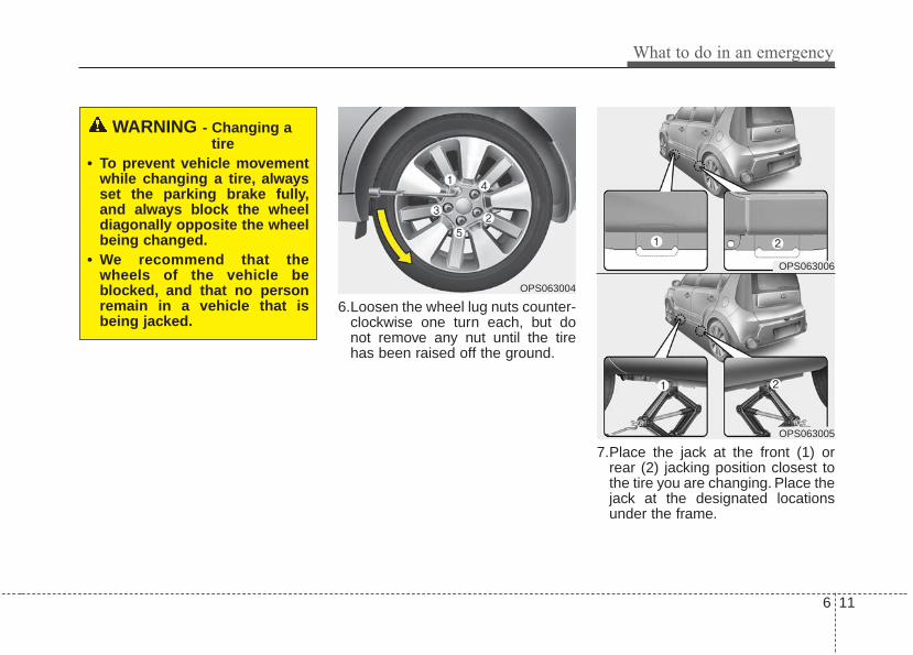
6 11
What to do in an emergency
6.Loosen the wheel lug nuts counter-clockwise one turn each, but donot remove any nut until the tirehas been raised off the ground.
7.Place the jack at the front (1) orrear (2) jacking position closest tothe tire you are changing. Place thejack at the designated locationsunder the frame.
OPS063004
WARNING - Changing atire
• To prevent vehicle movementwhile changing a tire, alwaysset the parking brake fully,and always block the wheeldiagonally opposite the wheelbeing changed.
• We recommend that thewheels of the vehicle beblocked, and that no personremain in a vehicle that isbeing jacked.
OPS063006
OPS063005

What to do in an emergency
126
8.Insert the jack handle into the jackand turn it clockwise, raising thevehicle until the tire just clears theground. This measurement isapproximately 30 mm. (1 in).Before removing the wheel lugnuts, make sure the vehicle is sta-ble and that there is no chance formovement or slippage.
9.Loosen the wheel nuts and removethem with your fingers. Slide thewheel off the studs and lay it flat soit cannot roll away. To put the wheelon the hub, pick up the spare tire,line up the holes with the studs andslide the wheel onto them. If this isdifficult, tip the wheel slightly andget the top hole in the wheel linedup with the top stud. Then jiggle thewheel back and forth until the wheelcan slide over the other studs.OAM069009
WARNING - Jack locationTo reduce the possibility ofinjury, be sure to use only thejack provided with the vehicle inthe correct jack position; neveruse any other part of the vehiclefor jack support.

6 13
What to do in an emergency
Wheels may have sharp edges.Handle them carefully to avoid possi-ble severe injury. Before putting thewheel into place, be sure that thereis nothing on the hub or wheel (suchas mud, tar, gravel, etc.) that pre-vents the wheel from fitting solidlyagainst the hub.
10. To install the wheel, hold it on thestuds, put the wheel nuts on thestuds and tighten them fingertight. Jiggle the tire to be sure it iscompletely seated, then tightenthe nuts as much as possiblewith your fingers again.
11. Insert the wrench into the jackand lower the vehicle to theground by turning the wheel nutwrench counterclockwise.
Then position the wrench as shownin the drawing and tighten the wheelnuts. Be sure the socket is seatedcompletely over the nut. Do not standon the wrench handle or use anextension pipe over the wrench han-dle. Go around the wheel tighteningevery nut following the numericalsequence shown in the image untilthey are all tight. Then double-checkeach nut for tightness. After changingwheels, have an authorized Kia deal-er tighten the wheel nuts to theirproper torque as soon as possible.
Wheel nut tightening torque:9~11 kg·m (65~79 lb·ft)
WARNING - Installing awheel
Make sure the wheel makesgood contact with the hub wheninstalled. If the contact of themounting surface between thewheel and hub is not good, thewheel nuts could come looseand cause the loss of a wheel.Loss of a wheel may result inloss of control of the vehicle.
OPS063007

What to do in an emergency
146
If you have a tire gauge, remove thevalve cap and check the air pressure.If the pressure is lower than recom-mended, drive slowly to the nearestservice station and inflate to the cor-rect pressure. If it is too high, adjustit until it is correct. Always reinstallthe valve cap after checking oradjusting the tire pressure. If the capis not replaced, dust and dirt may getinto the tire valve and air may leakfrom the tire. If you lose a valve cap,buy another and install it as soon aspossible.After you have changed the wheels,always secure the flat tire in its placeand return the jack and tools to theirproper storage locations.
Note that most lug nuts do not havemetric threads. Be sure to useextreme care in checking for threadstyle before installing aftermarket lugnuts or wheels. If in doubt, consult anauthorized Kia dealer.
To prevent the jack, jack handle,wheel lug nut wrench and spare tirefrom rattling while the vehicle is inmotion, store them properly.Check the inflation pressures assoon as possible after installing thespare tire. Adjust it to the specifiedpressure, if necessary. Refer to“Tires and wheels” in chapter 8.
CAUTION - Reusing lugnuts
Make certain during wheelremoval that the same nuts thatwere removed are reinstalled -or, if replaced, that nuts withmetric threads and the samechamfer configuration are used.Your vehicle has metric threadson the wheel studs and nuts.Installation of a non-metricthread nut on a metric stud willnot secure the wheel to the hubproperly and will damage thestud so that it must be replaced.
WARNING - Wheel studsIf the studs are damaged, theymay lose their ability to retainthe wheel.This could lead to theloss of the wheel and a colli-sion.

6 15
What to do in an emergency
Important - use of compact sparetire (if equipped)Your vehicle is equipped with a com-pact spare tire. This compact sparetire takes up less space than a regu-lar-size tire. This tire is smaller than aconventional tire and is designed fortemporary use only.• You should drive carefully when
the compact spare is in use. Thecompact spare should be replacedby the proper conventional tire andrim at the first opportunity.
• The operation of this vehicle is notrecommended with more than onecompact spare tire in use at thesame time.
The compact spare should be inflat-ed to 420 kPa (60 psi).
✽✽ NOTICECheck the inflation pressure afterinstalling the spare tire. Adjust it tothe specified pressure, as necessary.
When using a compact spare tire,observe the following precautions:• Under no circumstances should
you exceed 80 km/h (50 mph); ahigher speed could damage thetire.
• Ensure that you drive slowlyenough for the road conditions toavoid all hazards. Any road hazard,such as a pothole or debris, couldseriously damage the compactspare.
• Any continuous road use of this tirecould result in tire failure, loss ofvehicle control, and possible per-sonal injury.
• Do not exceed the vehicle’s maxi-mum load rating or the load-carry-ing capacity shown on the sidewallof the compact spare tire.
WARNING - Spare tireDo not operate your vehicle onthis compact spare at speedsover 80 km/h (50 mph). Thecompact spare tire is for emer-gency use only. The original tireshould be repaired or replacedas soon as possible to avoidfailure of the spare.

What to do in an emergency
166
• Avoid driving over obstacles. Thecompact spare tire diameter issmaller than the diameter of a con-ventional tire and reduces theground clearance approximately25 mm (1 inch), which could resultin damage to the vehicle.
• Do not take this vehicle through anautomatic vehicle wash while thecompact spare tire is installed.
• Do not use the compact spare tireon any other vehicle because thistire has been designed especiallyfor your vehicle.
• The compact spare tire’s tread lifeis shorter than a regular tire.Inspect your compact spare tireregularly and replace worn com-pact spare tires with the same sizeand design, mounted on the samewheel.
• The compact spare tire should notbe used on any other wheels, norshould standard tires, snow tires,wheel covers or trim rings be usedwith the compact spare wheel. Ifsuch use is attempted, damage tothese items or other vehicle com-ponents may occur.
• Do not use more than one compactspare tire at a time.
• Do not tow a trailer while the com-pact spare tire is installed.

6 17
What to do in an emergency
Jack label 1. Model Name2. Maximum allowable load3. When using the jack, set your
parking brake.4. When using the jack, stop the
engine.5. Do not get under a vehicle that is
supported by a jack.6. The designated locations under
the frame7. When supporting the vehicle, the
base plate of jack must be verticalunder the lifting point.
8. Shift into Reverse gear on vehicleswith manual transmission or movethe shift lever to the P position onvehicles with automatic transmis-sion.
9. The jack should be used on firmlevel ground.
10. Jack manufacturer11. Production date
OHYK064001
OHYK064002
■ Type A■ Example
■ Type B
❈ The actual Jack label in the vehicle may differ from the illustration. Formore detailed specifications, refer to the label attached to the jack.

What to do in an emergency
186
IF YOU HAVE A FLAT TIRE (TIRE MOBILITY KIT, IF EQUIPPED)
For safe operation, carefully readand follow the instructions in thismanual before use.(1) Compressor(2) Sealant bottleTire Mobility Kit is a temporary fix tothe tire and the tire should beinspected by an authorized Kia deal-er as soon as possible.
✽✽ NOTICEThe Tire Mobility Kit sealing com-pound in the bottle is to be used forone tire only. For additional replace-ment sealant bottles, consult anauthorized Kia dealer.
When two or more tires are flat, donot use the tire mobility kit becausethe supported one sealant of TireMobility Kit is only used for one flattire.
Introduction
With the Tire Mobility Kit you staymobile even after experiencing a tirepuncture.The system of compressor and seal-ing compound effectively and com-fortably seals most punctures in apassenger car tire caused by nails orsimilar objects and reinflates the tire.After you ensured that the tire is prop-erly sealed you can drive cautiouslyon the tire (distance up to 200 km (120miles)) at a max. speed of (80 km/h) inorder to reach a service station or tiredealer for the tire replacement.
OPS063008
OAM060013L
WARNING - Tire wallDo not use the Tire Mobility Kitto repair punctures in the tirewalls. This can result in an acci-dent due to tire failure.

6 19
What to do in an emergency
It is possible that some tires, espe-cially with larger punctures or dam-age to the sidewall, cannot be sealedcompletely.Air pressure loss in the tire mayadversely affect tire performance.For this reason, you should avoidabrupt steering or other drivingmaneuvers, especially if the vehicle isheavily loaded or if a trailer is in use.The Tire Mobility Kit is not designedor intended as a permanent tirerepair method and is to be used forone tire only.This instruction shows you step bystep how to temporarily seal thepuncture simply and reliably.Read the section "Notes on the safeuse of the Tire Mobility Kit".
Notes on the suggested use ofthe Tire Mobility Kit• Park your car at the side of the
road so that you can work with theTire Mobility Kit away from movingtraffic.
• To be sure your vehicle will notmove, even when you're on fairlylevel ground, always set your park-ing brake.
• Only use the Tire Mobility Kit forsealing/inflation passenger cartires. Only punctured areas locatedwithin the tread region of the tirecan be sealed using the tire mobil-ity kit.
• Do not use on motorcycles, bicy-cles or any other type of tires.
• When the tire and wheel are dam-aged, do not use Tire Mobility Kitfor your safety.
• Use of the Tire Mobility Kit may notbe effective for tire damage largerthan approximately 6 mm (0.24 in).Please contact the nearest Kiadealership if the tire cannot bemade roadworthy with the TireMobility Kit.
• Do not use the Tire Mobility Kit if atire is severely damaged by drivingrun flat or with insufficient air pres-sure.
• Do not remove any foreign objectssuch as nails or screws that havepenetrated the tire.
• Provided the car is outdoors, leavethe engine running. Otherwiseoperating the compressor mayeventually drain the car battery.
• Never leave the Tire Mobility Kitunattended while it is being used.
• Do not leave the compressor run-ning for more than 10 min. at a timeor it may overheat.
• Do not use the Tire Mobility Kit ifthe ambient temperature is below --30°C (22°F).

What to do in an emergency
206
0. Speed restriction label1. Sealant bottle and label with
speed restriction2. Filling hose from sealant bottle to
wheel3. Connectors and cable for the
power outlet direct connection
4. Holder for the sealant bottle5. Compressor6. On/off switch7. Pressure gauge for displaying the
tire inflation pressure8. Screw cap for reducing tire infla-
tion pressure
9. Hose to connect compressor andsealant bottle or compressor andwheel
Connectors, cable and connectionhose are stored in the compressorhousing.
Strictly follow the specifiedsequence, otherwise the sealantmay escape under high pressure.
Components of the Tire Mobility Kit
OAM060015L
WARNING - Expiredsealant
Do not use the Tire sealant afterthe sealant has expired (i.e.pasted the expiration date onthe sealant container). This canincrease the risk of tire failure.
WARNING - Sealant• Keep out of reach of children.• Avoid contact with eyes.• Do not swallow.

6 21
What to do in an emergency
Using the Tire Mobility Kit1. Detach the speed restriction label
(0) from the sealant bottle (1), andplace it in a highly visible placeinside the vehicle such as on thesteering wheel to remind the driv-er not to drive too fast.
2. Screw connection hose (9) ontothe connector of the sealant bottle.
3. Ensure that screw cap (8) isclosed.
4. Unscrew the valve cap from thevalve of the defective wheel andscrew filling hose (2) of the sealantbottle onto the valve.
5. Insert the sealant bottle into thehousing (4) of the compressor sothat the bottle is upright.
6. Ensure that the compressor isswitched off, position 0.
7.Plug the compressor power cordinto the front passenger side poweroutlet of the vehicle.
✽✽ NOTICEOnly use the front passenger sidepower outlet when connecting thepower cord.
OPS063008 OPS043204

What to do in an emergency
226
8. With the engine start/stop buttonposition on or ignition switch posi-tion on, switch on the compressorand let it run for approximately 5~7minutes to fill the sealant up toproper pressure. (refer to the Tireand Wheels, chapter 8). The infla-tion pressure of the tire after fillingis unimportant and will bechecked/corrected later.Be careful not to overinflate the tireand stay away from the tire whenfilling it.
9. Switch off the compressor.10. Detach the hoses from the
sealant bottle connector andfrom the tire valve.
Return the Tire Mobility Kit to its stor-age location in the vehicle.
Distributing the sealant11. Immediately drive approximately
7~10km (4~6miles or, about10min) to evenly distribute thesealant in the tire.
Do not exceed a speed of 80 km/h(50 mph). If possible, do not fallbelow a speed of 20 km/h (12 mph).While driving, if you experience anyunusual vibration, ride disturbance ornoise, reduce your speed and drivewith caution until you can safely pulloff of the side of the road.Call for road side service or towing.When you use the Tire Mobility Kit,the tire pressure sensors and wheelmay be stained by sealant.Therefore, remove the tire pressuresensors and wheel stained bysealant and have it serviced by anauthorized Kia dealer.
WARNING - Carbonmonoxide
Do not leave your vehicle run-ning in a poorly ventilated areafor extended periods of time.Carbon monoxide poisoningand suffocation can occur.WARNING - Tire pressure
Do not attempt to drive yourvehicle if the tire pressure isbelow 200kpa (29 PSI). Thiscould result in an accident dueto sudden tire failure.

6 23
What to do in an emergency
Checking the tire inflation pres-sure1.After driving approximately
7~10km (4~6miles or about10min), stop at a safety location.
2.Connect connection hose (9) of thecompressor directly to the tirevalve.
3.Plug the compressor power cordinto the vehicle power outlet.
4.Adjust the tire inflation pressure tothe recommended tire inflation.With the ignition switched on, pro-ceed as follows.- To increase the inflation pres-
sure : Switch on the compressor,position I. To check the currentinflation pressure setting, brieflyswitch off the compressor.
✽✽ NOTICEThe pressure gauge may show high-er than actual reading when thecompressor is running. To get anaccurate tire pressure, the compres-sor needs to be turned off.
- To reduce the inflation pres-sure: Loosen the screw cap (8)on the compressor hose.
CAUTION - Tire pressuresensor
When you use the Tire MobilityKit including sealant notapproved by Kia, the tire pres-sure sensors may be damagedby sealant. The sealant on thetire pressure sensor and wheelshould be removed when youreplace the tire with a new oneand inspect the tire pressuresensors in authorized dealer.

What to do in an emergency
246
Technical DataSystem voltage: DC 12 VWorking voltage: DC 10 - 15 VAmperage rating: max. 15 ASuitable for use at temperatures:
-30 ~ +70°C (-22 ~ +158°F)Max. working pressure:
6 bar (87 psi)Size Compressor: 170 x 150 x 60 mm
(6.7 x 5.9 x 2.4 in.)Sealant bottle: 85 x 70 ø mm
(3.3 x 2.8 ø in.)Compressor weight:
0.8 kg (1.77 lbs)Sealant volume:
200 ml (12.2 cu. in.)

6 25
What to do in an emergency
TOWINGTowing service
If emergency towing is necessary,we recommend having it done by anauthorized Kia dealer or a commer-cial tow-truck service. Proper liftingand towing procedures are neces-sary to prevent damage to the vehi-cle. The use of wheel dollies orflatbed is recommended.
For trailer towing guidelines informa-tion, refer to “Trailer towing” in chap-ter 5.
It is acceptable to tow the vehiclewith the rear wheels on the ground(without dollies) and the front wheelsoff the ground.If any of the loaded wheels or sus-pension components are damagedor the vehicle is being towed with thefront wheels on the ground, use atowing dolly under the front wheels.When being towed by a commercialtow truck and wheel dollies are notused, the front of the vehicle shouldalways be lifted, not the rear.
OXM069028
dolly
dolly
WARNING - Side and curtain air bag
If your vehicle is equipped withside and curtain air bag, set theignition switch to LOCK or ACCposition when the vehicle isbeing towed.The side and curtain air bagmay deploy when the ignitionsis ON, and the rollover sensordetects the situation as arollover.

What to do in an emergency
266
When towing your vehicle in anemergency without wheel dollies :1. Set the ignition switch in the ACC
position.2. Place the transaxle shift lever in N
(Neutral).3. Release the parking brake.
Removable towing hook (front) (if equipped)
1.Remove the towing hook from thetool case.
2.Remove the hole cover pressingthe lower part of the cover on thefront bumper.
CAUTION - Towing gearposition
Failure to place the transaxleshift lever in N (Neutral) maycause internal damage to thetransaxle.
CAUTION - Towing• Do not tow the vehicle back-
wards with the front wheels onthe ground as this may causedamage to the vehicle.
• Do not tow with sling-typeequipment. Use wheel lift orflatbed equipment.
OUN046030
OCM054034
OPS063009

6 27
What to do in an emergency
3.Install the towing hook by turning itclockwise into the hole until it isfully secured.
4.Remove the towing hook andinstall the cover after use.
Emergency towing
If towing is necessary, we recom-mend you to have it done by anauthorized Kia dealer or a com-mercial tow truck service.
If towing service is not available in anemergency, your vehicle may betemporarily towed using a cable orchain secured to the emergency tow-ing hook under the front (or rear) ofthe vehicle. Use extreme cautionwhen towing the vehicle. A drivermust be in the vehicle to steer it andoperate the brakes.Towing in this manner may be doneonly on hard-surfaced roads for ashort distance and at low speeds.Also, the wheels, axles, power train,steering and brakes must all be ingood condition.• Do not use the tow hooks to pull a
vehicle out of mud, sand or otherconditions from which the vehiclecannot be driven out under its ownpower.
• Avoid towing a vehicle heavier thanthe vehicle doing the towing.
• The drivers of both vehicles shouldcommunicate with each other fre-quently.
OPS063010 OPS063010
OPS063012
Front
Rear (if equipped)

What to do in an emergency
286
• Attach a towing strap to the towhook.
• Using a portion of the vehicle otherthan the tow hooks for towing maydamage the body of your vehicle.
• Only use a cable or chain specifi-cally intended for use in towing vehi-cles. Securely fasten the cable orchain to the towing hook provided.
• Before emergency towing, checkthat the hook is not broken or dam-aged.
• Fasten the towing cable or chainsecurely to the hook.
• Do not jerk the hook. Apply itsteadily and with even force.
• To avoid damaging the hook, donot pull from the side or at a verti-cal angle. Always pull straightahead.
• Use a towing strap less than 5 m(16 feet) long. Attach a white or redcloth (about 30 cm (12 inches)wide) in the middle of the strap foreasy visibility.
• Drive carefully so that the towingstrap is not loose during towing.
Emergency towing precautions• Turn the ignition switch to ACC so
the steering wheel isn’t locked.• Place the transaxle shift lever in N
(Neutral).• Release the parking bake.• Press the brake pedal with more
force than usual since you will havereduced brake performance.
• More steering effort will berequired because the power steer-ing system will be disabled.
• If you are driving down a long hill,the brakes may overheat and brakeperformance will be reduced. Stopoften and let the brakes cool off.
• If the car is being towed with allfour wheels on the ground, it canbe towed only from the front. Besure that the transaxle is in neutral.Be sure the steering is unlocked byplacing the ignition switch in theACC position. A driver must be inthe towed vehicle to operate thesteering and brakes.
OPA067014

6 29
What to do in an emergency
✽✽ NOTICEBefore towing, check the automatictransaxle for fluid leaks under yourvehicle. If the automatic transaxlefluid is leaking, a flatbed equipmentor towing dolly must be used.
CAUTION - Automatictransaxle
To avoid serious damage to theautomatic transaxle, limit thevehicle speed to 15 km/h (10mph) and drive less than 1.5 km(1 mile) when towing.

Maintenance
Engine compartment . . . . . . . . . . . . . . . . . . . . . . . . 7-3Maintenance services . . . . . . . . . . . . . . . . . . . . . . . . 7-5
• Owner’s responsibility . . . . . . . . . . . . . . . . . . . . . . . . . 7-5• Owner maintenance precautions . . . . . . . . . . . . . . . . . 7-6
Owner maintenance . . . . . . . . . . . . . . . . . . . . . . . . . 7-7• Owner maintenance schedule. . . . . . . . . . . . . . . . . . . . 7-7
Scheduled maintenance service. . . . . . . . . . . . . . . . 7-9Explanation of scheduled maintenance items . . . 7-32Engine oil. . . . . . . . . . . . . . . . . . . . . . . . . . . . . . . . . 7-36
• Checking the engine oil level . . . . . . . . . . . . . . . . . . . 7-36• Changing the engine oil and filter . . . . . . . . . . . . . . . 7-37
Engine coolant . . . . . . . . . . . . . . . . . . . . . . . . . . . . 7-38• Checking the coolant level . . . . . . . . . . . . . . . . . . . . . 7-38• Changing the coolant . . . . . . . . . . . . . . . . . . . . . . . . . 7-40
Brake/clutch fluid. . . . . . . . . . . . . . . . . . . . . . . . . . 7-41• Checking the brake/clutch fluid level . . . . . . . . . . . . 7-41
Washer fluid . . . . . . . . . . . . . . . . . . . . . . . . . . . . . . 7-43• Checking the washer fluid level . . . . . . . . . . . . . . . . . 7-43
Parking brake . . . . . . . . . . . . . . . . . . . . . . . . . . . . . 7-44• Checking the parking brake. . . . . . . . . . . . . . . . . . . . 7-44
Air cleaner. . . . . . . . . . . . . . . . . . . . . . . . . . . . . . . . 7-45• Filter replacement . . . . . . . . . . . . . . . . . . . . . . . . . . . . 7-45
Climate control air filter . . . . . . . . . . . . . . . . . . . . 7-47• Filter inspection . . . . . . . . . . . . . . . . . . . . . . . . . . . . . . 7-47
• Filter replacement . . . . . . . . . . . . . . . . . . . . . . . . . . . . 7-47Wiper blades . . . . . . . . . . . . . . . . . . . . . . . . . . . . . . 7-49
• Blade inspection. . . . . . . . . . . . . . . . . . . . . . . . . . . . . . 7-49• Blade replacement . . . . . . . . . . . . . . . . . . . . . . . . . . . . 7-49
Battery . . . . . . . . . . . . . . . . . . . . . . . . . . . . . . . . . . . 7-53• For best battery service . . . . . . . . . . . . . . . . . . . . . . . 7-53• Battery recharging . . . . . . . . . . . . . . . . . . . . . . . . . . . 7-54• Reset items . . . . . . . . . . . . . . . . . . . . . . . . . . . . . . . . . . 7-55
Tires and wheels . . . . . . . . . . . . . . . . . . . . . . . . . . . 7-56• Tire care . . . . . . . . . . . . . . . . . . . . . . . . . . . . . . . . . . . . 7-56• Recommended cold tire inflation pressures . . . . . . . 7-56• Checking tire inflation pressure. . . . . . . . . . . . . . . . . 7-57• Tire rotation . . . . . . . . . . . . . . . . . . . . . . . . . . . . . . . . . 7-58• Wheel alignment and tire balance . . . . . . . . . . . . . . . 7-59• Tire replacement . . . . . . . . . . . . . . . . . . . . . . . . . . . . . 7-60• Wheel replacement . . . . . . . . . . . . . . . . . . . . . . . . . . . 7-61• Tire traction . . . . . . . . . . . . . . . . . . . . . . . . . . . . . . . . . 7-61• Tire maintenance . . . . . . . . . . . . . . . . . . . . . . . . . . . . . 7-61• Tire sidewall labeling . . . . . . . . . . . . . . . . . . . . . . . . . 7-62• Low aspect ratio tire . . . . . . . . . . . . . . . . . . . . . . . . . . 7-69
Fuses . . . . . . . . . . . . . . . . . . . . . . . . . . . . . . . . . . . . 7-71• Inner panel fuse replacement. . . . . . . . . . . . . . . . . . . 7-73• Engine compartment fuse replacement. . . . . . . . . . . 7-74• Fuse/relay panel description. . . . . . . . . . . . . . . . . . . . 7-76
7

Light bulbs . . . . . . . . . . . . . . . . . . . . . . . . . . . . . . . 7-84• Front light replacement . . . . . . . . . . . . . . . . . . . . . . . 7-84• Side repeater light bulb replacement . . . . . . . . . . . . 7-90• Rear combination light bulb replacement . . . . . . . . 7-91• High mounted stop light bulb replacement . . . . . . . 7-93• License plate light bulb replacement. . . . . . . . . . . . . 7-94• Interior light bulb replacement . . . . . . . . . . . . . . . . . 7-95
Appearance care . . . . . . . . . . . . . . . . . . . . . . . . . . . 7-96• Exterior care . . . . . . . . . . . . . . . . . . . . . . . . . . . . . . . . 7-96• Interior care . . . . . . . . . . . . . . . . . . . . . . . . . . . . . . . . 7-102
Emission control system . . . . . . . . . . . . . . . . . . . 7-104
7

7 3
Maintenance
ENGINE COMPARTMENT
OPS073001
1. Windshield washer fluid reservoir
2. Engine oil filler cap
3. Engine oil dipstick
4. Engine coolant reservoir
5. Radiator cap
6. Brake fluid reservoir
7. Positive battery terminal
8. Negative battery terminal
9. Fuse box
10. Air cleaner
* The actual engine compartment in the vehicle may differ from the illustration.
■■ 1.6L GDI

Maintenance
47
OPS073002
* The actual engine room in the vehicle may differ from the illustration.
1. Engine coolant reservoir
2. Engine oil filler cap
3. Brake fluid reservoir
4. Air cleaner
5. Fuse box
6. Positive battery terminal
7. Negative battery terminal
8. Windshield washer fluid reservoir
9. Radiator cap
10. Engine oil dipstick
* : if equipped
■■ 2.0L GDI

7 5
Maintenance
MAINTENANCE SERVICESYou should exercise the utmost careto prevent damage to your vehicleand injury to yourself whenever per-forming any maintenance or inspec-tion procedures.Should you have any doubts con-cerning the inspection or servicing ofyour vehicle, we strongly recom-mend that you have an authorizedKia dealer perform this work.An authorized Kia dealer has factorytrained technicians and genuine Kiaparts to service your vehicle proper-ly. For expert advice and quality serv-ice, see an authorized Kia dealer.Inadequate, incomplete or insuffi-cient servicing may result in opera-tional problems with your vehicle thatcould lead to vehicle damage, anaccident, or personal injury.
Owner’s responsibility
✽✽ NOTICEMaintenance Service and RecordRetention are the owner's responsi-bility. You should retain documents thatshow proper maintenance has beenperformed on your vehicle in accor-dance with the scheduled mainte-nance service charts shown on thefollowing pages. You need this infor-mation to establish your compliancewith the servicing and maintenancerequirements of your vehicle war-ranties.Detailed warranty information isprovided in your Warranty &Consumer Information manual.
Repairs and adjustments required asa result of improper maintenance ora lack of required maintenance arenot covered.
We recommend you have your vehi-cle maintained and repaired by anauthorized Kia dealer. An authorizedKia dealer meets Kia’s high servicequality standards and receives tech-nical support from Kia in order to pro-vide you with a high level of servicesatisfaction.

Maintenance
67
Owner maintenance precau-tions Improper or incomplete service mayresult in problems. This section givesinstructions only for the maintenanceitems that are easy to perform.As explained earlier in this section,several procedures can be done onlyby an authorized Kia dealer with spe-cial tools.
✽✽ NOTICEImproper owner maintenance dur-ing the warranty period may affectwarranty coverage. For details, readthe separate Warranty & ConsumerInformation manual provided withthe vehicle. If you're unsure aboutany servicing or maintenance proce-dure, have it done by an authorizedKia dealer.
WARNING - Maintenancework
Do not wear jewelry or looseclothing while working underthe hood of your vehicle withthe engine running. These canbecome entangled in movingparts, if you must run the enginewhile working under the hood,make certain that you removeall jewelry (especially rings,bracelets, watches, and neck-laces) and all neckties, scarves,and similar loose clothingbefore getting near the engineor cooling fans.

7 7
Maintenance
OWNER MAINTENANCE The following lists are vehicle checksand inspections that should be per-formed by the owner or an author-ized Kia dealer at the frequenciesindicated to help ensure safe,dependable operation of your vehi-cle.Any adverse conditions should bebrought to the attention of your deal-er as soon as possible.These Owner Maintenance Checksare generally not covered by war-ranties and you may be charged forlabor, parts and lubricants used.
Owner maintenance schedule When you stop for fuel:• Check the engine oil level.• Check the coolant level in the
coolant reservoir.• Check the windshield washer fluid
level.• Look for low or under-inflated tires.
Check if the front of the radiatorand condenser are clean and notblocked with leaves, dirt or insectsetc. If any of the above parts areextremely dirty or you are not sureof their condition, take your vehicleto an authorized Kia dealer.
While operating your vehicle:• Note any changes in the sound of
the exhaust or any smell ofexhaust fumes in the vehicle.
• Check for vibrations in the steeringwheel. Notice any increased steer-ing effort or looseness in the steer-ing wheel, or change in its straight-ahead position.
• Notice if your vehicle constantlyturns slightly or “pulls” to one sidewhen traveling on smooth, levelroad.
• When stopping, listen and checkfor unusual sounds, pulling to oneside, increased brake pedal travelor “hard-to-push” brake pedal.
• If any slipping or changes in theoperation of your transaxle occurs,check the transaxle fluid level.
• Check the automatic transaxle P(Park) function.
• Check the parking brake.• Check for fluid leaks under your
vehicle (water dripping from the airconditioning system during or afteruse is normal).
WARNING - Hot coolantBe careful when checking yourengine coolant level when theengine is hot. Scalding hotcoolant and steam may blowout under pressure.

Maintenance
87
At least monthly:• Check the coolant level in the
engine coolant reservoir.• Check the operation of all exterior
lights, including the stoplights, turnsignals and hazard warning flash-ers.
• Check the inflation pressures of alltires including the spare.
At least twice a year (i.e., every Spring and Fall):• Check the radiator, heater and air
conditioning hoses for leaks ordamage.
• Check the windshield washerspray and wiper operation. Cleanthe wiper blades with clean clothdampened with washer fluid.
• Check the headlight alignment.• Check the muffler, exhaust pipes,
shields and clamps.• Check the lap/shoulder belts for
wear and function.• Check for worn tires and loose
wheel lug nuts.
At least once a year:• Clean the body and door drain
holes.• Lubricate the door hinges and
checks, and hood hinges.• Lubricate the door and hood locks
and latches.• Lubricate the door rubber weather-
strips.• Check the air conditioning system.• Inspect and lubricate the automat-
ic transaxle linkage and controls.• Clean the battery and terminals.• Check the brake fluid level.

7 9
Maintenance
SCHEDULED MAINTENANCE SERVICE Follow the Normal MaintenanceSchedule if the vehicle is usuallyoperated where none of the followingconditions apply. If any of the follow-ing conditions apply, follow theMaintenance Under Severe UsageConditions.• Repeated short distance driving.• Driving in dusty conditions or
sandy areas.• Extensive use of brakes.• Driving in areas where salt or other
corrosive materials are being used.• Driving on rough or muddy roads.• Driving in mountainous areas.• Extended periods of idling or low
speed operation.• Driving for a prolonged period in
cold temperatures and/or extreme-ly humid climates.
• More than 50% driving in heavycity traffic during hot weatherabove 32°C (90°F).
If your vehicle is operated under theabove conditions, you shouldinspect, replace or refill more fre-quently than the following NormalMaintenance Schedule. After 120months or 240,000 km (150,000miles) continue to follow the pre-scribed maintenance intervals.

Maintenance
107
NORMAL MAINTENANCE SCHEDULE
The following maintenance services must be performed to ensure good emission control and performance. Keepreceipts for all vehicle emission services to protect your warranty. Where both mileage and time are shown, the fre-quency of service is determined by whichever occurs first.
*1 lnspect "Water Pump" when replacing the drive belt ortiming belt.
*2 Fuel filter & Fuel tank air filter are considered to bemaintenance free but periodic inspection is recom-mended for this maintenance schedule depends onfuel quality. If there are some important safety matterslike fuel flow restriction, surging, loss of power, hardstarting problem etc, replace the fuel filter immediatelyregardless of maintenance schedule and consult anauthorized Kia dealer for details.
*3 Inspect for excessive tappet noise and/or engine vibra-tion and adjust if necessary.
*4 The drive belt should be replaced when cracks occuror tension is reduced excessively.
*5 When replacing coolant, use only a qualified coolantadditive for your vehicle and never mix hard water inthe coolant filled at the factory. An improper coolantmixture can result in serious malfunction or enginedamage.
*6 If TOP TIER Detergent Gasoline is not available, onebottle of additive is recommended. Additives are avail-able from your authorized Kia dealer along with infor-mation on how to use them. Do not mix other additives.

7 11
Maintenance
12,000 km or 6 months
❑ Inspect air cleaner filter
❑ Inspect air conditioning compressor, air conditioner refriger-ant and performance (if equipped)
❑ Inspect cooling system *1
❑ Inspect drive shaft and boots
❑ Inspect visually the following items.1) Battery condition2) Brake fluid / clutch(if equipped) fluid3) Fuel lines, hoses and connections4) Brake pedal and operation5) Chassis/body nuts and bolts6) Drum brake and linings (if equipped)7) Disc brakes and pads(if equipped)8) Exhaust pipe and muffler9) Front suspension ball joints10) Fuel tank, cap, lines and hoses11) Lubricate all locks and hinges12) Parking brakes13) Steering operation and linkage14) Suspension mounting bolts
(Continued)
(Continued)
❑ Replace engine oil and filter(Every 12,000 km or 12 months)
❑ Add fuel additive *6
(Every 12,000 km or 12 months)
❑ Rotate tires - including tire pressure and tread wear(Every 12,000 km or 12 months)
NORMAL MAINTENANCE SCHEDULE (CONT.)
❈ Inspect : Inspect and if necessary, adjust, correct, clean orreplace.

Maintenance
127
NORMAL MAINTENANCE SCHEDULE (CONT.)24,000 km or 12 months
❑ Inspect air cleaner filter
❑ Inspect air conditioning compressor, air conditioner refriger-ant and performance (if equipped)
❑ Inspect cooling system *1
❑ Inspect drive shaft and boots
❑ Inspect visually the following items1) Battery condition2) Brake fluid / clutch(if equipped) fluid3) Fuel lines, hoses and connections4) Brake pedal and operation5) Chassis/body nuts and bolts6) Drum brake and linings (if equipped)7) Disc brakes and pads(if equipped)8) Exhaust pipe and muffler9) Front suspension ball joints10) Fuel tank, cap, lines and hoses11) Lubricate all locks and hinges12) Parking brakes13) Steering operation and linkage14) Suspension mounting bolts
❑ Replace climate control air filter (if equipped)
❑ Replace engine oil and filter(Every 12,000 km or 12 months)
(Continued)
(Continued)
❑ Add fuel additive *6
(Every 12,000 km or 12 months)
❑ Rotate tires - including tire pressure and tread wear(Every 12,000 km or 12 months)
❈ Inspect : Inspect and if necessary, adjust, correct, clean orreplace.

7 13
Maintenance
(Continued)
❑ Replace engine oil and filter(Every 12,000 km or 12 months)
❑ Add fuel additive *6
(Every 12,000 km or 12 months)
❑ Rotate tires - including tire pressure and tread wear(Every 12,000 km or 12 months)
NORMAL MAINTENANCE SCHEDULE (CONT.)
❈ Inspect : Inspect and if necessary, adjust, correct, clean orreplace.
36,000 km or 18 months
❑ Inspect air cleaner filter
❑ Inspect air conditioning compressor, air conditioner refriger-ant and performance (if equipped)
❑ Inspect cooling system *1
❑ Inspect drive shaft and boots
❑ Inspect visually the following items.1) Battery condition2) Brake fluid / clutch(if equipped) fluid3) Fuel lines, hoses and connections4) Brake pedal and operation5) Chassis/body nuts and bolts6) Drum brake and linings (if equipped)7) Disc brakes and pads(if equipped)8) Exhaust pipe and muffler9) Front suspension ball joints10) Fuel tank, cap, lines and hoses11) Lubricate all locks and hinges12) Parking brakes13) Steering operation and linkage14) Suspension mounting bolts
(Continued)

Maintenance
147
NORMAL MAINTENANCE SCHEDULE (CONT.)48,000 km or 24 months
❑ Inspect air conditioning compressor, air conditioner refrig-erant and performance (if equipped)
❑ Inspect cooling system *1
❑ Inspect drive shaft and boots
❑ Inspect fuel filter *2
❑ Inspect fuel line, hoses and connection
❑ Inspect fuel tank air filter *2
❑ Inspect manual transaxle fluid (if equipped)(Every 60,000 km or 48 months)
❑ Inspect vapor hose and fuel filler cap
❑ Inspect visually the following items1) Battery condition2) Brake fluid / clutch (if equipped) fluid3) Fuel lines, hoses and connections4) Brake pedal and operation5) Chassis/body nuts and bolts6) Drum brake and linings (if equipped)7) Disc brakes and pads (if equipped)8) Exhaust pipe and muffler9) Front suspension ball joints10) Fuel tank, cap, lines and hoses11) Lubricate all locks and hinges
(Continued)
(Continued)
12) Parking brakes13) Steering operation and linkage14) Suspension mounting bolts
❑ Replace air cleaner filter
❑ Replace climate control air filter (if equipped)
❑ Replace engine oil and filter(Every 12,000 km or 12 months)
❑ Add fuel additive *6
(Every 12,000 km or 12 months)
❑ Rotate tires - including tire pressure and tread wear(Every 12,000 km or 12 months)
❈ Inspect : Inspect and if necessary, adjust, correct, clean orreplace.

7 15
Maintenance
60,000 km or 30 months
❑ Inspect air cleaner filter
❑ Inspect air conditioning compressor, air conditioner refriger-ant and performance (if equipped)
❑ Inspect cooling system *1
❑ Inspect drive shaft and boots
❑ Inspect visually the following items.1) Battery condition2) Brake fluid / clutch(if equipped) fluid3) Fuel lines, hoses and connections4) Brake pedal and operation5) Chassis/body nuts and bolts6) Drum brake and linings (if equipped)7) Disc brakes and pads(if equipped)8) Exhaust pipe and muffler9) Front suspension ball joints10) Fuel tank, cap, lines and hoses11) Lubricate all locks and hinges12) Parking brakes13) Steering operation and linkage14) Suspension mounting bolts
(Continued)
(Continued)
❑ Replace engine oil and filter(Every 12,000 km or 12 months)
❑ Add fuel additive *6
(Every 12,000 km or 12 months)
❑ Rotate tires - including tire pressure and tread wear(Every 12,000 km or 12 months)
NORMAL MAINTENANCE SCHEDULE (CONT.)
❈ Inspect : Inspect and if necessary, adjust, correct, clean orreplace.

Maintenance
167
(Continued)
❑ Replace climate control air filter (if equipped)
❑ Replace engine oil and filter(Every 12,000 km or 12 months)
❑ Add fuel additive *6 (Every 12,000 km or 12 months)
❑ Rotate tires - including tire pressure and tread wear(Every 12,000 km or 12 months)
72,000 km or 36 months
❑ Inspect air cleaner filter
❑ Inspect air conditioning compressor, air conditioner refrig-erant and performance (if equipped)
❑ Inspect cooling system *1
❑ Inspect drive shaft and boots
❑ Inspect visually the following items1) Battery condition2) Brake fluid / clutch (if equipped) fluid3) Fuel lines, hoses and connections4) Brake pedal and operation5) Chassis/body nuts and bolts6) Drum brake and linings (if equipped)7) Disc brakes and pads (if equipped)8) Exhaust pipe and muffler9) Front suspension ball joints10) Fuel tank, cap, lines and hoses11) Lubricate all locks and hinges12) Parking brakes13) Steering operation and linkage14) Suspension mounting bolts
(Continued)
NORMAL MAINTENANCE SCHEDULE (CONT.)
❈ Inspect : Inspect and if necessary, adjust, correct, clean orreplace.

7 17
Maintenance
84,000 km or 42 months
❑ Inspect air cleaner filter
❑ Inspect air conditioning compressor, air conditioner refriger-ant and performance (if equipped)
❑ Inspect cooling system *1
❑ Inspect drive shaft and boots
❑ Inspect visually the following items.1) Battery condition2) Brake fluid / clutch(if equipped) fluid3) Fuel lines, hoses and connections4) Brake pedal and operation5) Chassis/body nuts and bolts6) Drum brake and linings (if equipped)7) Disc brakes and pads(if equipped)8) Exhaust pipe and muffler9) Front suspension ball joints10) Fuel tank, cap, lines and hoses11) Lubricate all locks and hinges12) Parking brakes13) Steering operation and linkage14) Suspension mounting bolts
(Continued)
(Continued)
❑ Replace engine oil and filter(Every 12,000 km or 12 months)
❑ Add fuel additive *6
(Every 12,000 km or 12 months)
❑ Rotate tires - including tire pressure and tread wear(Every 12,000 km or 12 months)
NORMAL MAINTENANCE SCHEDULE (CONT.)
❈ Inspect : Inspect and if necessary, adjust, correct, clean orreplace.

Maintenance
187
NORMAL MAINTENANCE SCHEDULE (CONT.)96,000 km or 48 months
❑ Inspect air conditioning compressor, air conditioner refrig-erant and performance (if equipped)
❑ Inspect cooling system *1
❑ Inspect drive belt *4
(First, 96,000 km or 72 months after every 24,000 km or 24 months)
❑ Inspect drive shaft and boots
❑ Inspect fuel filter *2
❑ Inspect fuel line, hoses and connection
❑ Inspect fuel tank air filter *2
❑ Inspect vapor hose and fuel filler cap
❑ Inspect visually the following items1) Battery condition2) Brake fluid / clutch (if equipped) fluid3) Fuel lines, hoses and connections4) Brake pedal and operation5) Chassis/body nuts and bolts6) Drum brake and linings (if equipped)7) Disc brakes and pads (if equipped)
(Continued)
(Continued)
8) Exhaust pipe and muffler9) Front suspension ball joints10) Fuel tank, cap, lines and hoses11) Lubricate all locks and hinges12) Parking brakes13) Steering operation and linkage14) Suspension mounting bolts
❑ Replace air cleaner filter
❑ Replace climate control air filter (if equipped)
❑ Replace engine oil and filter(Every 12,000 km or 12 months)
❑ Add fuel additive *6
(Every 12,000 km or 12 months)
❑ Rotate tires - including tire pressure and tread wear(Every 12,000 km or 12 months)
❈ Inspect : Inspect and if necessary, adjust, correct, clean orreplace.

7 19
Maintenance
108,000 km or 54 months
❑ Inspect air cleaner filter
❑ Inspect air conditioning compressor, air conditioner refriger-ant and performance (if equipped)
❑ Inspect cooling system *1
❑ Inspect drive shaft and boots
❑ Inspect visually the following items.1) Battery condition2) Brake fluid / clutch(if equipped) fluid3) Fuel lines, hoses and connections4) Brake pedal and operation5) Chassis/body nuts and bolts6) Drum brake and linings (if equipped)7) Disc brakes and pads(if equipped)8) Exhaust pipe and muffler9) Front suspension ball joints10) Fuel tank, cap, lines and hoses11) Lubricate all locks and hinges12) Parking brakes13) Steering operation and linkage14) Suspension mounting bolts
(Continued)
(Continued)
❑ Replace engine oil and filter(Every 12,000 km or 12 months)
❑ Add fuel additive *6
(Every 12,000 km or 12 months)
❑ Rotate tires - including tire pressure and tread wear(Every 12,000 km or 12 months)
NORMAL MAINTENANCE SCHEDULE (CONT.)
❈ Inspect : Inspect and if necessary, adjust, correct, clean orreplace.

Maintenance
207
NORMAL MAINTENANCE SCHEDULE (CONT.)120,000 km or 60 months
❑ Inspect air cleaner filter
❑ Inspect air conditioning compressor, air conditioner refrig-erant and performance (if equipped)
❑ Inspect cooling system *1
❑ Inspect drive belt *4
(First 96,000 km or 72 months after every 24,000 km or 24 months)
❑ Inspect drive shaft and boots
❑ Inspect manual transaxle fluid (if equipped)(Every 60,000 km or 48 months)
❑ Inspect visually the following items1) Battery condition2) Brake fluid / clutch (if equipped) fluid3) Fuel lines, hoses and connections4) Brake pedal and operation5) Chassis/body nuts and bolts6) Drum brake and linings (if equipped)7) Disc brakes and pads (if equipped)
(Continued)
(Continued)
8) Exhaust pipe and muffler9) Front suspension ball joints10) Fuel tank, cap, lines and hoses11) Lubricate all locks and hinges12) Parking brakes13) Steering operation and linkage14) Suspension mounting bolts
❑ Replace climate control air filter (if equipped)
❑ Replace engine oil and filter(Every 12,000 km or 12 months)
❑ Add fuel additive *6
(Every 12,000 km or 12 months)
❑ Rotate tires - including tire pressure and tread wear(Every 12,000 km or 12 months)
❈ Inspect : Inspect and if necessary, adjust, correct, clean orreplace.

7 21
Maintenance
132,000 km or 66 months
❑ Inspect air cleaner filter
❑ Inspect air conditioning compressor, air conditioner refriger-ant and performance (if equipped)
❑ Inspect cooling system *1
❑ Inspect drive shaft and boots
❑ Inspect visually the following items.1) Battery condition2) Brake fluid / clutch(if equipped) fluid3) Fuel lines, hoses and connections4) Brake pedal and operation5) Chassis/body nuts and bolts6) Drum brake and linings (if equipped)7) Disc brakes and pads(if equipped)8) Exhaust pipe and muffler9) Front suspension ball joints10) Fuel tank, cap, lines and hoses11) Lubricate all locks and hinges12) Parking brakes13) Steering operation and linkage14) Suspension mounting bolts
(Continued)
(Continued)
❑ Replace engine oil and filter(Every 12,000 km or 12 months)
❑ Add fuel additive *6
(Every 12,000 km or 12 months)
❑ Rotate tires - including tire pressure and tread wear(Every 12,000 km or 12 months)
NORMAL MAINTENANCE SCHEDULE (CONT.)
❈ Inspect : Inspect and if necessary, adjust, correct, clean orreplace.

Maintenance
227
NORMAL MAINTENANCE SCHEDULE (CONT.)144,000 km or 72 months
❑ Inspect air conditioning compressor, air conditioner refrig-erant and performance (if equipped)
❑ Inspect cooling system *1
❑ Inspect drive belt *4
(First 96,000 km or 72 months after every 24,000 km or 24 months)
❑ Inspect drive shaft and boots
❑ Inspect fuel filter *2
❑ Inspect fuel line, hoses and connection
❑ Inspect fuel tank air filter *2
❑ Inspect valve clearance (Engine 1.6) *3
❑ Inspect vapor hose and fuel filler cap
❑ Inspect visually the following items1) Battery condition2) Brake fluid / clutch (if equipped) fluid3) Fuel lines, hoses and connections4) Brake pedal and operation5) Chassis/body nuts and bolts6) Drum brake and linings (if equipped)7) Disc brakes and pads (if equipped)8) Exhaust pipe and muffler
(Continued)
(Continued)
9) Front suspension ball joints10) Fuel tank, cap, lines and hoses11) Lubricate all locks and hinges12) Parking brakes13) Steering operation and linkage14) Suspension mounting bolts
❑ Replace air cleaner filter
❑ Replace climate control air filter (if equipped)
❑ Replace engine oil and filter(Every 12,000 km or 12 months)
❑ Add fuel additive *6
(Every 12,000 km or 12 months)
❑ Rotate tires - including tire pressure and tread wear(Every 12,000 km or 12 months)
❈ Inspect : Inspect and if necessary, adjust, correct, clean orreplace.

7 23
Maintenance
156,000 km or 78 months
❑ Inspect air cleaner filter
❑ Inspect air conditioning compressor, air conditioner refriger-ant and performance (if equipped)
❑ Inspect cooling system *1
❑ Inspect drive shaft and boots
❑ Inspect visually the following items.1) Battery condition2) Brake fluid / clutch(if equipped) fluid3) Fuel lines, hoses and connections4) Brake pedal and operation5) Chassis/body nuts and bolts6) Drum brake and linings (if equipped)7) Disc brakes and pads(if equipped)8) Exhaust pipe and muffler9) Front suspension ball joints10) Fuel tank, cap, lines and hoses11) Lubricate all locks and hinges12) Parking brakes13) Steering operation and linkage14) Suspension mounting bolts
(Continued)
(Continued)
❑ Replace engine oil and filter(Every 12,000 km or 12 months)
❑ Add fuel additive *6
(Every 12,000 km or 12 months)
❑ Rotate tires - including tire pressure and tread wear(Every 12,000 km or 12 months)
NORMAL MAINTENANCE SCHEDULE (CONT.)
❈ Inspect : Inspect and if necessary, adjust, correct, clean orreplace.

Maintenance
247
(Continued)
11) Lubricate all locks and hinges12) Parking brakes13) Steering operation and linkage14) Suspension mounting bolts
❑ Replace climate control air filter (if equipped)
❑ Replace engine oil and filter(Every 12,000 km or 12 months)
❑ Add fuel additive *6
(Every 12,000 km or 12 months)
❑ Replace spark plugs (iridium coated),
❑ Rotate tires - including tire pressure and tread wear(Every 12,000 km or 12 months)
NORMAL MAINTENANCE SCHEDULE (CONT.)168,000 km or 84 months
❑ Inspect air cleaner filter
❑ Inspect air conditioning compressor, air conditioner refrig-erant and performance (if equipped)
❑ Inspect cooling system *1
❑ Inspect drive belt *4
(First 96,000 km or 72 months after every 24,000 km or 24 months)
❑ Inspect drive shaft and boots
❑ Inspect manual transaxle fluid (if equipped)(Every 60,000 km or 48 months)
❑ Inspect visually the following items1) Battery condition2) Brake fluid / clutch (if equipped) fluid3) Fuel lines, hoses and connections4) Brake pedal and operation5) Chassis/body nuts and bolts6) Drum brake and linings (if equipped)7) Disc brakes and pads (if equipped)8) Exhaust pipe and muffler9) Front suspension ball joints10) Fuel tank, cap, lines and hoses
(Continued)
❈ Inspect : Inspect and if necessary, adjust, correct, clean orreplace.

7 25
Maintenance
180,000 km or 90 months
❑ Inspect air cleaner filter
❑ Inspect air conditioning compressor, air conditioner refriger-ant and performance (if equipped)
❑ Inspect cooling system *1
❑ Inspect drive shaft and boots
❑ Inspect visually the following items.1) Battery condition2) Brake fluid / clutch(if equipped) fluid3) Fuel lines, hoses and connections4) Brake pedal and operation5) Chassis/body nuts and bolts6) Drum brake and linings (if equipped)7) Disc brakes and pads(if equipped)8) Exhaust pipe and muffler9) Front suspension ball joints10) Fuel tank, cap, lines and hoses11) Lubricate all locks and hinges12) Parking brakes13) Steering operation and linkage14) Suspension mounting bolts
(Continued)
(Continued)
❑ Replace engine oil and filter(Every 12,000 km or 12 months)
❑ Add fuel additive *6
(Every 12,000 km or 12 months)
❑ Rotate tires - including tire pressure and tread wear(Every 12,000 km or 12 months)
NORMAL MAINTENANCE SCHEDULE (CONT.)
❈ Inspect : Inspect and if necessary, adjust, correct, clean orreplace.

Maintenance
267
NORMAL MAINTENANCE SCHEDULE (CONT.)192,000 km or 96 months
❑ Inspect air conditioning compressor, air conditioner refrig-erant and performance (if equipped)
❑ Inspect cooling system *1
❑ Inspect drive belt *4
(First 96,000 km or 72 months after every 24,000 km or 24 months)
❑ Inspect drive shaft and boots
❑ Inspect fuel filter *2
❑ Inspect fuel line, hoses and connection
❑ Inspect fuel tank air filter *2
❑ Inspect vapor hose and fuel filler cap
❑ Inspect visually the following items1) Battery condition2) Brake fluid / clutch (if equipped) fluid3) Fuel lines, hoses and connections4) Brake pedal and operation5) Chassis/body nuts and bolts6) Drum brake and linings (if equipped)7) Disc brakes and pads (if equipped)8) Exhaust pipe and muffler9) Front suspension ball joints
(Continued)
(Continued)
10) Fuel tank, cap, lines and hoses11) Lubricate all locks and hinges12) Parking brakes13) Steering operation and linkage14) Suspension mounting bolts
❑ Replace air cleaner filter
❑ Replace climate control air filter (if equipped)
❑ Replace engine coolant*5
(First, 192,000 km or 120 months after every 48,000 km or 24 months)
❑ Replace engine oil and filter(Every 12,000 km or 12 months)
❑ Add fuel additive *6 (Every 12,000 km or 12 months)
❑ Rotate tires - including tire pressure and tread wear(Every 12,000 km or 12 months)
❈ Inspect : Inspect and if necessary, adjust, correct, clean orreplace.

7 27
Maintenance
204,000 km or 102 months
❑ Inspect air cleaner filter
❑ Inspect air conditioning compressor, air conditioner refriger-ant and performance (if equipped)
❑ Inspect cooling system *1
❑ Inspect drive shaft and boots
❑ Inspect visually the following items.1) Battery condition2) Brake fluid / clutch(if equipped) fluid3) Fuel lines, hoses and connections4) Brake pedal and operation5) Chassis/body nuts and bolts6) Drum brake and linings (if equipped)7) Disc brakes and pads(if equipped)8) Exhaust pipe and muffler9) Front suspension ball joints10) Fuel tank, cap, lines and hoses11) Lubricate all locks and hinges12) Parking brakes13) Steering operation and linkage14) Suspension mounting bolts
(Continued)
(Continued)
❑ Replace engine oil and filter(Every 12,000 km or 12 months)
❑ Add fuel additive *6
(Every 12,000 km or 12 months)
❑ Rotate tires - including tire pressure and tread wear(Every 12,000 km or 12 months)
NORMAL MAINTENANCE SCHEDULE (CONT.)
❈ Inspect : Inspect and if necessary, adjust, correct, clean orreplace.

Maintenance
287
NORMAL MAINTENANCE SCHEDULE (CONT.)216,000 km or 108 months
❑ Inspect air cleaner filter
❑ Inspect air conditioning compressor, air conditioner refrig-erant and performance (if equipped)
❑ Inspect cooling system *1
❑ Inspect drive belt *4
(First 96,000 km or 72 months after every 24,000 km or 24 months)
❑ Inspect drive shaft and boots
❑ Inspect visually the following items1) Battery condition2) Brake fluid / clutch (if equipped) fluid3) Fuel lines, hoses and connections4) Brake pedal and operation5) Chassis/body nuts and bolts6) Drum brake and linings (if equipped)7) Disc brakes and pads (if equipped)8) Exhaust pipe and muffler9) Front suspension ball joints10) Fuel tank, cap, lines and hoses11) Lubricate all locks and hinges12) Parking brakes13) Steering operation and linkage14) Suspension mounting bolts
(Continued)
(Continued)
❑ Replace climate control air filter (if equipped)
❑ Replace engine oil and filter(Every 12,000 km or 12 months)
❑ Add fuel additive *6
(Every 12,000 km or 12 months)
❑ Rotate tires - including tire pressure and tread wear(Every 12,000 km or 12 months)
❈ Inspect : Inspect and if necessary, adjust, correct, clean orreplace.
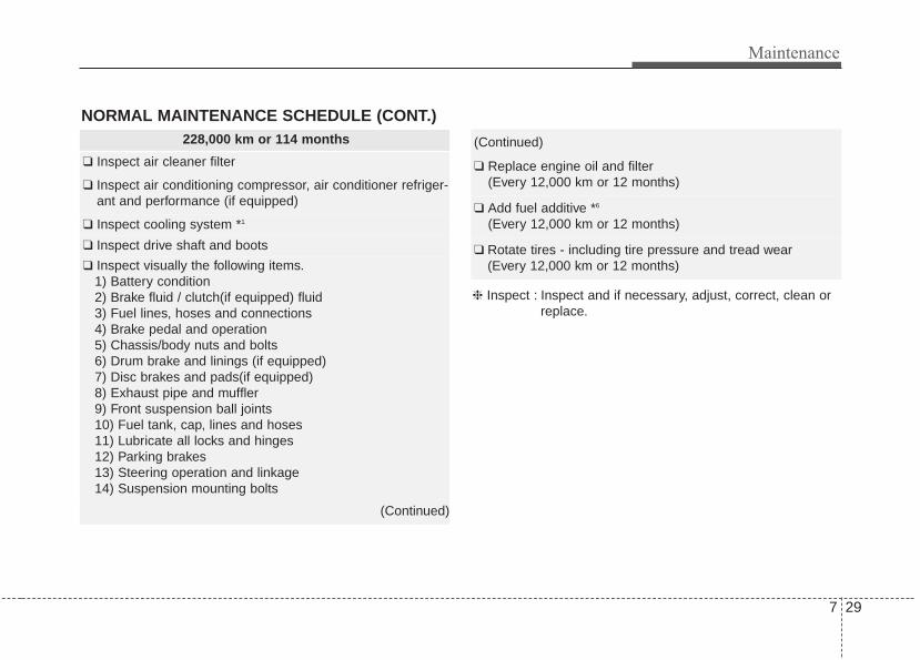
7 29
Maintenance
228,000 km or 114 months
❑ Inspect air cleaner filter
❑ Inspect air conditioning compressor, air conditioner refriger-ant and performance (if equipped)
❑ Inspect cooling system *1
❑ Inspect drive shaft and boots
❑ Inspect visually the following items.1) Battery condition2) Brake fluid / clutch(if equipped) fluid3) Fuel lines, hoses and connections4) Brake pedal and operation5) Chassis/body nuts and bolts6) Drum brake and linings (if equipped)7) Disc brakes and pads(if equipped)8) Exhaust pipe and muffler9) Front suspension ball joints10) Fuel tank, cap, lines and hoses11) Lubricate all locks and hinges12) Parking brakes13) Steering operation and linkage14) Suspension mounting bolts
(Continued)
(Continued)
❑ Replace engine oil and filter(Every 12,000 km or 12 months)
❑ Add fuel additive *6
(Every 12,000 km or 12 months)
❑ Rotate tires - including tire pressure and tread wear(Every 12,000 km or 12 months)
NORMAL MAINTENANCE SCHEDULE (CONT.)
❈ Inspect : Inspect and if necessary, adjust, correct, clean orreplace.

Maintenance
307
240,000 km or 120 months
❑ Inspect air conditioning compressor, air conditioner refrig-erant and performance (if equipped)
❑ Inspect cooling system *1
❑ Inspect drive belt *4
(First 96,000 km or 72 months after every 24,000 km or 24 months)
❑ Inspect drive shaft and boots
❑ Inspect fuel filter *2
❑ Inspect fuel line, hoses and connection
❑ Inspect fuel tank air filter *2
❑ Inspect manual transaxle fluid (if equipped)(Every 60,000 km or 48 months)
❑ Inspect vapor hose and fuel filler cap
❑ Inspect visually the following items1) Battery condition2) Brake fluid / clutch (if equipped) fluid3) Fuel lines, hoses and connections4) Brake pedal and operation5) Chassis/body nuts and bolts6) Drum brake and linings (if equipped)7) Disc brakes and pads (if equipped)
(Continued)
(Continued)
8) Exhaust pipe and muffler9) Front suspension ball joints10) Fuel tank, cap, lines and hoses11) Lubricate all locks and hinges12) Parking brakes13) Steering operation and linkage14) Suspension mounting bolts
❑ Replace air cleaner filter
❑ Replace climate control air filter (if equipped)
❑ Replace engine coolant *5
(First 192,000 km or 120 months after every 48,000 km or 24 months)
❑ Replace engine oil and filter(Every 12,000 km or 12 months)
❑ Add fuel additive *6
(Every 12,000 km or 12 months)
❑ Rotate tires - including tire pressure and tread wear(Every 12,000 km or 12 months)
NORMAL MAINTENANCE SCHEDULE (CONT.)
No check, No service required
❑ Automatic transaxle fluid (if equipped)
❈ Inspect : Inspect and if necessary, adjust, correct, clean orreplace.

7 31
Maintenance
MAINTENANCE UNDER SEVERE USAGE CONDITIONSThe following items must be serviced more frequently on cars normally used under severe driving conditions. Referto the chart below for the appropriate maintenance intervals.R : Replace I : Inspect and, after inspection, clean, adjust, repair or replace if necessary
R
R
R
I
I
I
I
R
R
R
EVERY 6,000 km OR 6 months
MORE FREQUENTLY
MORE FREQUENTLY
MORE FREQUENTLY
MORE FREQUENTLY
MORE FREQUENTLY
EVERY 12,000 km OR 6 months
EVERY 120,000 km
EVERY 90,000 km
MORE FREQUENTLY
A, B, C, D, E, F, G, H, I, J, K
C, E
A, B, H, I, K
C, D, G, H
C, D, G, H
C, D, E, F, G, H, I
C, D, E, F, G, H
C, D, F, G, H, I, J
A, C, E, F, G, H, I
C, E
ENGINE OIL AND FILTER
AIR CLEANER FILTER
SPARK PLUGS
DISC BRAKE/ PADS, CALIPERS AND ROTORS
REAR BRAKE DRUMS/ LININGS, PARKING BRAKE
STEERING GEAR BOX, LINKAGE & BOOTS/ LOWER
ARM BALL JOINT, UPPER ARM BSALL JOINT
DRIVE SHAFTS AND BOOTS
MANUAL TRANSAXLE OIL
AUTOMATIC TRANSAXLE FLUID
CLIMATE CONTROL AIR FILTER
(FOR EVAPORATOR AND BLOWER UNIT)
MAINTENANCE ITEM MAINTENANCEOPERATION
MAINTENANCEINTERVALS
DRIVINGCONDITION
SEVERE DRIVING CONDITIONS
A - Repeatedly driving shorts distanse of less than 8 km in normal tem-perature or less than 16 km in freezing temperature
B - Extensive engine idling or low speed driving for long distancesC - Driving on rough, dusty, muddy, unpaved, graveled or salt-spread
roadsD - Driving in areas using salt or other corrosive materials or in very
cold weather
E - Driving in sandy areasF - Driving in heavy traffic area over 32°C (90°F)G - Driving on uphill, downhill, or mountain roadH - Towing a Trailer, or using a camper, or roof rackI - Driving as a patrol car, taxi, other commercial use or vehicle towingJ - Driving over 170 km/hK - Frequently driving in stop-and-go conditions

Maintenance
327
EXPLANATION OF SCHEDULED MAINTENANCE ITEMSEngine oil and filterThe engine oil and filter should bechanged at the intervals specified inthe maintenance schedule. If thevehicle is being driven in severe con-ditions, more frequent oil and filterchanges are required.
Drive beltsInspect all drive belts for evidence ofcuts, cracks, excessive wear or oilsaturation and replace if necessary.Drive belts should be checked peri-odically for proper tension andadjusted as necessary.
Fuel filter (cartridge)A clogged filter can limit the speed atwhich the vehicle may be driven,damage the emission system andcause multiple issues such as hardstarting. If an excessive amount offoreign matter accumulates in thefuel tank, the filter may requirereplacement more frequently.After installing a new filter, run theengine for several minutes, andcheck for leaks at the connections.Fuel filters should be installed by anauthorized Kia dealer.
Fuel lines, fuel hoses and con-nectionsCheck the fuel lines, fuel hoses andconnections for leakage and dam-age. Have an authorized Kia dealerreplace any damaged or leakingparts immediately.
Vapor hose and fuel filler capThe vapor hose and fuel filler capshould be inspected at those inter-vals specified in the maintenanceschedule. Make sure that a newvapor hose or fuel filler cap is cor-rectly replaced.

7 33
Maintenance
Vacuum crankcase ventilationhoses (if equipped) Inspect the surface of hoses for evi-dence of heat and/or mechanicaldamage. Hard and brittle rubber,cracking, tears, cuts, abrasions, andexcessive swelling indicate deterio-ration. Particular attention should bepaid to examine those hose surfacesnearest to high heat sources, suchas the exhaust manifold.Inspect the hose routing to assurethat the hoses do not come in con-tact with any heat source, sharpedges or moving components whichmight cause heat damage ormechanical wear. Inspect all hoseconnections, such as clamps andcouplings, to make sure they aresecure, and that no leaks are pres-ent. Hoses should be replacedimmediately if there is any evidenceof deterioration or damage.
Air cleaner filterA Genuine Kia air cleaner filter isrecommended when the filter isreplaced.
Spark plugsMake sure to install new spark plugsof the correct heat range.
Valve clearance (if equipped)Inspect for excessive valve noiseand/or engine vibration and adjust ifnecessary. An authorized Kia dealershould perform the operation.
Cooling systemCheck the cooling system compo-nents, such as the radiator, coolantreservoir, hoses and connections forleakage and damage. Replace anydamaged parts.
CoolantThe coolant should be changed atthe intervals specified in the mainte-nance schedule.

Maintenance
347
Automatic transaxle fluid (if equipped)Automatic transaxle fluid should notbe checked under normal usageconditions.But in severe conditions, the fluidshould be changed at an authorizedKia dealer in accordance to thescheduled maintenance at the begin-ning of this section.
✽✽ NOTICEAutomatic transaxle fluid color isbasically red. As the vehicle is driven, the auto-matic transaxle fluid will begin tolook darker.It is the normal condition and youshould not judge the need to replacethe fluid based upon the changedcolor.
Manual transaxle fluid (if equipped)Inspect the manual transaxle fluidaccording to the maintenance sched-ule.
Brake hoses and linesVisually check for proper installation,chafing, cracks, deterioration andany leakage. Replace any deteriorat-ed or damaged parts immediately.
Brake/clutch (if equipped) fluidCheck the brake fluid level in thebrake fluid reservoir. The level shouldbe between “MIN” and “MAX” markson the side of the reservoir. Use onlyhydraulic brake fluid conforming toDOT 3 or DOT 4 specification.
Parking brakeInspect the parking brake systemincluding the parking brake lever (orpedal) and cables.
CAUTION - Transaxle fluids
The use of a non-specified fluidcould result in transaxle mal-function and failure.Use only specified automatictransaxle fluid. (Refer to"Recommended lubricants andcapacities" in section 8.)

7 35
Maintenance
Brake discs, pads, calipersand rotorsCheck the pads for excessive wear,discs for run out and wear, andcalipers for fluid leakage.For more information on checking thepads or lining wear limit, we recom-mend you to refer to the Kia website.(http://www.kiatechinfo.com)
Exhaust pipe and mufflerVisually inspect the exhaust pipes,muffler and hangers for cracks, dete-rioration, or damage. Start the engineand listen carefully for any exhaustgas leakage. Tighten connections orreplace parts as necessary.
Suspension mounting boltsCheck the suspension connectionsfor looseness or damage. Retightento the specified torque.
Steering gear box, linkage &boots/lower arm ball jointWith the vehicle stopped and engineoff, check for excessive free-play inthe steering wheel.Check the linkage for bends or dam-age. Check the dust boots and balljoints for deterioration, cracks, or dam-age. Replace any damaged parts.
Drive shafts and bootsCheck the drive shafts, boots andclamps for cracks, deterioration, ordamage. Replace any damaged partsand, if necessary, repack the grease.
Air conditioning refrigerant Check the air conditioning lines andconnections for leakage and damage.
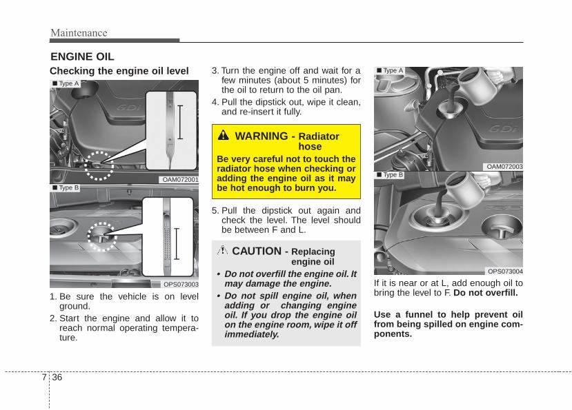
Maintenance
367
ENGINE OILChecking the engine oil level
1. Be sure the vehicle is on levelground.
2. Start the engine and allow it toreach normal operating tempera-ture.
3. Turn the engine off and wait for afew minutes (about 5 minutes) forthe oil to return to the oil pan.
4. Pull the dipstick out, wipe it clean,and re-insert it fully.
5. Pull the dipstick out again andcheck the level. The level shouldbe between F and L.
If it is near or at L, add enough oil tobring the level to F. Do not overfill.
Use a funnel to help prevent oilfrom being spilled on engine com-ponents.
WARNING - Radiatorhose
Be very careful not to touch theradiator hose when checking oradding the engine oil as it maybe hot enough to burn you.
CAUTION - Replacingengine oil
• Do not overfill the engine oil. Itmay damage the engine.
• Do not spill engine oil, whenadding or changing engineoil. If you drop the engine oilon the engine room, wipe it offimmediately.
OAM072001
OPS073003
■ Type A
■ Type B
OAM072003
OPS073004
■ Type A
■ Type B

7 37
Maintenance
Use only the specified engine oil.(Refer to “Recommended lubricantsand capacities” in chapter 8.)
Changing the engine oil andfilterHave engine oil and filter changed byan authorized Kia dealer accordingto the Maintenance Schedule at thebeginning of this chapter.
WARNINGUsed engine oil may cause irri-tation or cancer of the skin ifleft in contact with the skin forprolonged periods of time.Always protect your skin bywashing your hands thoroughlywith soap and warm water assoon as possible after handlingused oil.

Maintenance
387
ENGINE COOLANTThe high-pressure cooling systemhas a reservoir filled with year roundantifreeze coolant. The reservoir isfilled at the factory.Check the antifreeze protection andcoolant level at least once a year, atthe beginning of the winter season,and before traveling to a colder cli-mate.
Checking the coolant level
Turn the engine off and wait until itcools down. Use extreme care whenremoving the radiator cap. Wrap athick towel around it, and turn itcounterclockwise slowly to the firststop. Step back while the pressure isreleased from the cooling system.When you are sure all the pressurehas been released, press down onthe cap, using a thick towel, and con-tinue turning counterclockwise toremove it.
CAUTIONNever attempt to remove theradiator cap while the engine isoperating or hot. Doing somight lead to cooling systemand engine damage.
WARNING - Cooling fanUse caution whenworking near theblade of the coolingfan. The electricmotor (cooling fan) is
controlled by engine coolanttemperature, refrigerant pres-sure and vehicle speed. it maysometimes operate even whenthe engine is not running.
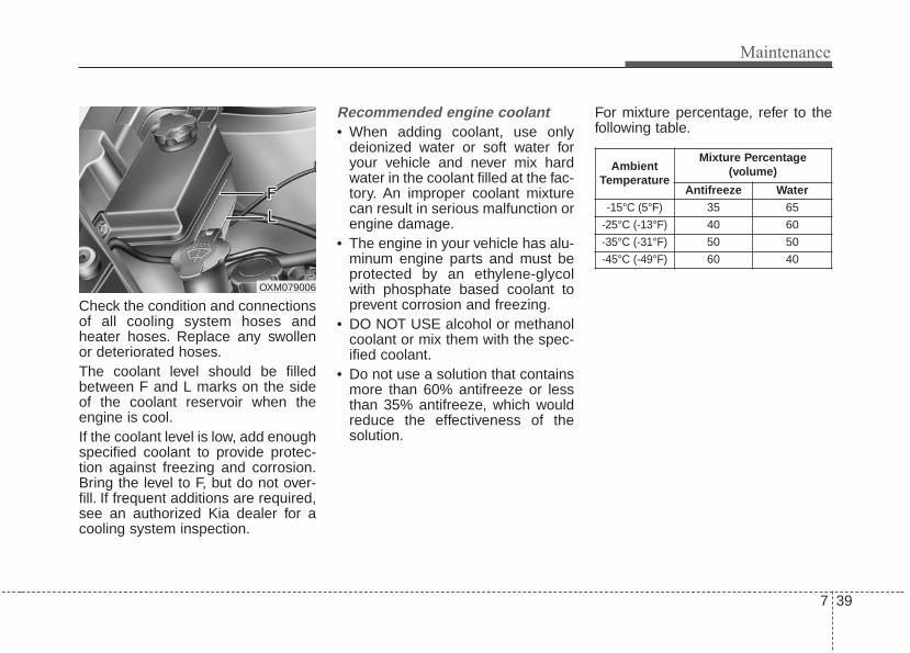
7 39
Maintenance
Check the condition and connectionsof all cooling system hoses andheater hoses. Replace any swollenor deteriorated hoses.The coolant level should be filledbetween F and L marks on the sideof the coolant reservoir when theengine is cool.If the coolant level is low, add enoughspecified coolant to provide protec-tion against freezing and corrosion.Bring the level to F, but do not over-fill. If frequent additions are required,see an authorized Kia dealer for acooling system inspection.
Recommended engine coolant• When adding coolant, use only
deionized water or soft water foryour vehicle and never mix hardwater in the coolant filled at the fac-tory. An improper coolant mixturecan result in serious malfunction orengine damage.
• The engine in your vehicle has alu-minum engine parts and must beprotected by an ethylene-glycolwith phosphate based coolant toprevent corrosion and freezing.
• DO NOT USE alcohol or methanolcoolant or mix them with the spec-ified coolant.
• Do not use a solution that containsmore than 60% antifreeze or lessthan 35% antifreeze, which wouldreduce the effectiveness of thesolution.
For mixture percentage, refer to thefollowing table.
OXM079006
AmbientTemperature
Mixture Percentage (volume)
Antifreeze Water-15°C (5°F) 35 65
-25°C (-13°F) 40 60
-35°C (-31°F) 50 50
-45°C (-49°F) 60 40

Maintenance
407
Changing the coolantHave the coolant changed by anauthorized Kia dealer according tothe Maintenance Schedule at thebeginning of this chapter.Put a thick cloth around the radiatorcap before refilling the coolant inorder to prevent the coolant fromoverflowing into engine parts such asthe alternator.
OPS073005
WARNING Radiator cap
Do not remove the radiator capwhen the engine and radiatorare hot. Scalding hot coolantand steam may blow out underpressure which may result inserious injury.

7 41
Maintenance
BRAKE/CLUTCH FLUIDChecking the brake/clutch*fluid level
Check the fluid level in the reservoirperiodically. The fluid level should bebetween MAX and MIN marks on theside of the reservoir.Before removing the reservoir capand adding brake/clutch* fluid, cleanthe area around the reservoir capthoroughly to prevent brake/clutch*fluid contamination.
* if equipped
If the level is low, add fluid to theMAX level. The level will fall withaccumulated mileage. This is a nor-mal condition associated with thewear of the brake linings and/orclutch disc (if equipped). If the fluidlevel is excessively low, have thebrake/clutch* system checked by anauthorized KIA dealer.
Use only the specified brake/clutch*fluid. (Refer to “Recommended lubri-cants and capacities” in chapter 8.)
Never mix different types of fluid.
In the event the brake/clutch* systemrequires frequent additions of fluid,the vehicle should be inspected byan authorized Kia dealer.When changing and addingbrake/clutch* fluid, handle it carefully.Do not let it come in contact withyour eyes. If brake/ clutch* fluidshould come in contact with youreyes, immediately flush them with alarge quantity of fresh tap water.Have your eyes examined by a doc-tor as soon as possible.
OXM079008
CAUTION - Proper fluidOnly use brake fluid in brakesystem. Small amounts ofimproper fluids (such as engineoil) can cause damage to thebrake system.

Maintenance
427
Brake/clutch* fluid, which has beenexposed to open air for an extendedtime should never be used as itsquality cannot be guaranteed. Itshould be disposed of properly.
CAUTION - Brake/clutch*fluid
Do not allow brake/clutch* fluidto contact the vehicle's bodypaint, as paint damage willresult.

7 43
Maintenance
WASHER FLUIDChecking the washer fluidlevel
The reservoir is translucent so thatyou can check the level with a quickvisual inspection.
Check the fluid level in the washerfluid reservoir and add fluid if neces-sary. Plain water may be used ifwasher fluid is not available.However, use washer solvent withantifreeze characteristics in cold cli-mates to prevent freezing.
OPS073006
OPS073007
■ Type A
■ Type B
WARNING - FlammableFluid
Do not allow the washer fluid tocome in contact with openflames or sparks. The wind-shield washer fluid reservoir isflammable under certain cir-cumstances.This can result in afire.
WARNING - Coolant• Do not use radiator coolant or
antifreeze in the washer fluidreservoir.
• Radiator coolant can severelyobscure visibility whensprayed on the windshieldand may cause loss of vehiclecontrol.
WARNING - Windshieldfluid
Do not drink the windshieldwasher fluid. The windshieldwasher fluid is poisonous tohumans and animals.

Maintenance
447
PARKING BRAKE Checking the parking brake
Check the stroke of the parkingbrake by counting the number of“clicks’’ heard while fully applying itfrom the released position. Also, theparking brake alone should securelyhold the vehicle on a fairly steepgrade. If the stroke is more or lessthan specified, have the parkingbrake adjusted by an authorized Kiadealer.
Stroke : 6~8 “clicks’’ at a force of 20 kg (44 lbs, 196 N).
OPS053011

7 45
Maintenance
Filter replacement
It must be replaced when necessary,and should not be washed.You can clean the filter when inspect-ing the air cleaner element.Clean the filter by using compressedair.
1. Loosen the air cleaner coverattaching clips and open the cover.
2. Wipe the inside of the air cleaner.3. Replace the air cleaner filter.4. Lock the cover with the cover
attaching clips.
AIR CLEANER
OAM079043
OAM079044 OAM079046

Maintenance
467
Replace the filter according to theMaintenance Schedule.If the vehicle is operated in extreme-ly dusty or sandy areas, replace theelement more often than the usualrecommended intervals. (Refer to“Maintenance under severe usageconditions” in this chapter.)
CAUTION - Air filter maintenance
• Do not drive with the air clean-er removed; this will result inexcessive engine wear.
• When removing the air cleanerfilter, be careful that dust ordirt does not enter the airintake, or damage may result.
• Use a Kia genuine part. Use ofnon-genuine parts could dam-age the air flow sensor.

7 47
Maintenance
CLIMATE CONTROL AIR FILTER (IF EQUIPPED)Filter inspectionThe climate control air filter shouldbe replaced according to the mainte-nance schedule. If the vehicle isoperated in severely air-pollutedcities or on dusty rough roads for along period, it should be inspectedmore frequently and replaced earlier.When you replace the climate controlair filter, replace it performing the fol-lowing procedure, and be careful toavoid damaging other components.
Filter replacement
1. Open the glove box.
2. With the glove box open, removethe Air filter cover.
OPS073009
OPS073008

Maintenance
487
3. Remove the climate control air fil-ter case by pulling out both sidesof the cover.
4. Replace the climate control air filter.5. Reassemble in the reverse order
of disassembly.When replacing the climate controlair filter install it properly. Otherwise,the system may produce noise andthe effectiveness of the filter may bereduced.
OPS073010 OPS073011

7 49
Maintenance
WIPER BLADES Blade inspection
Commercial hot waxes applied byautomatic vehicle washes have beenknown to make the windshield diffi-cult to clean.
Contamination of either the wind-shield or the wiper blades with for-eign matter can reduce the effective-ness of the windshield wipers.Common sources of contaminationare insects, tree sap, and hot waxtreatments used by some commer-cial vehicle washes. If the blades arenot wiping properly, clean both thewindow and the blades with a goodcleaner or mild detergent, and rinsethoroughly with clean water.
Blade replacement When the wipers no longer cleanadequately, the blades may be wornor cracked, and require replacement.To prevent damage to the wiper armsor other components, do not attemptto move the wipers manually.The use of a non-specified wiperblade could result in wiper malfunc-tion and failure.
1JBA5122CAUTION - Wiper blades
To prevent damage to the wiperblades, do not use gasoline,kerosene, paint thinner, or othersolvents on or near them.

Maintenance
507
Front windshield wiper blade
Type A
1. Raise the wiper arm and turn thewiper blade assembly to exposethe plastic locking clip.
2. Compress the clip and slide theblade assembly downward.
3. Lift it off the arm.4. Install the blade assembly in the
reverse order of removal.
Type B
1. Raise the wiper arm.1LDA5023
CAUTION - Wiper armsDo not allow the wiper arm tofall against the windshield,since it may chip or crack thewindshield.
1JBA7037
1JBA7038
OHM078059
CAUTION - Wiper armsDo not allow the wiper arm tofall against the windshield,since it may chip or crack thewindshield.

7 51
Maintenance
2. Lift up the wiper blade clip. Thenpull down the blade assembly andremove it.
3. Install the new blade assembly inthe reverse order of removal.
Rear window wiper blade
1. Raise the wiper arm and pull outthe wiper blade assembly.
OHM078060
OHM078062
OHM078061
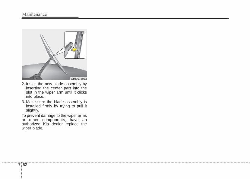
Maintenance
527
2. Install the new blade assembly byinserting the center part into theslot in the wiper arm until it clicksinto place.
3. Make sure the blade assembly isinstalled firmly by trying to pull itslightly.
To prevent damage to the wiper armsor other components, have anauthorized Kia dealer replace thewiper blade.
OHM078063

7 53
Maintenance
BATTERYFor best battery service
• Keep the battery securely mount-ed.
• Keep the battery top clean and dry.• Keep the terminals and connec-
tions clean, tight, and coated withpetroleum jelly or terminal grease.
• Rinse any spilled electrolyte fromthe battery immediately with asolution of water and baking soda.
• If the vehicle is not going to beused for an extended time, discon-nect the battery cables.
OXM079100
WARNING - Risk of explosion
Keep lit cigarettes andall other flames orsparks away from thebattery.The battery containshydrogen -- a highlycombustible gas whichwill explode if it comesin contact with a flame orspark.
WARNING - Sulfuric acidin batteries
Keep batteries out of thereach of childrenbecause batteries con-tain highly corrosiveSULFURIC ACID andelectrolytes. Do notallow battery acid tocontact your skin, eyes,clothing or paint finish.Wear eye protectionwhen charging or work-ing near a battery.Always provide ventila-tion when working in anenclosed space.

Maintenance
547
Always read the followinginstructions carefully whenhandling a battery.If any electrolyte gets intoyour eyes, flush your eyeswith clean water for at least15 minutes and get immedi-ate medical attention.If electrolyte gets on yourskin, thoroughly wash thecontacted area. If you feelpain or burning sensation,get medical attention imme-diately.An inappropriately disposedbattery can be harmful to theenvironment and humanhealth. Dispose the batteryaccording to your locallaw(s) or regulation.
✽✽ NOTICEIf you connect unauthorized elec-tronic devices to the battery, the bat-tery may be discharged. Never useunauthorized devices.
Battery recharging Your vehicle has a maintenance-free,calcium-based battery.• If the battery becomes discharged
in a short time (because, for exam-ple, the headlights or interior lightswere left on while the vehicle wasnot in use), recharge it by slowcharging (trickle) for 10 hours.
• If the battery gradually dischargesbecause of high electric load whilethe vehicle is being used, rechargeit at 20-30A for two hours.
WARNING - Risk of elec-trocution
Never touch the electrical igni-tion system while the vehicle isrunning. This system workswith high voltage which can"zap" you.
WARNING - Rechargingbattery
Never attempt to recharge thebattery when the battery cablesare connected.

7 55
Maintenance
When recharging the battery,observe the following precautions:• The battery must be removed from
the vehicle and placed in an areawith good ventilation.
• Do not allow cigarettes, sparks, orflame near the battery.
• Watch the battery during charging,and stop or reduce the chargingrate if the battery cells begingassing (boiling) violently or if thetemperature of the electrolyte ofany cell exceeds 49°C (120°F).
• Wear eye protection when check-ing the battery during charging.
• Disconnect the battery charger inthe following order.1. Turn off the battery charger main
switch.2. Unhook the negative clamp from
the negative battery terminal.3. Unhook the positive clamp from
the positive battery terminal.
• Before performing maintenance orrecharging the battery, turn off allaccessories and stop the engine.
• The negative battery cable must beremoved first and installed lastwhen the battery is disconnected.
Reset itemsItems should be reset after the bat-tery has been discharged or the bat-tery has been disconnected.• Auto up/down window
(See chapter 4)• Sunroof (See chapter 4)• Trip computer (See chapter 4)• Climate control system
(See chapter 4)• Clock (See chapter 4)• Audio (See chapter 4)

Maintenance
567
TIRES AND WHEELSTire care For proper maintenance, safety, andmaximum fuel economy, you mustalways maintain recommended tireinflation pressures and stay withinthe load limits and weight distributionrecommended for your vehicle.
Recommended cold tire infla-tion pressuresAll tire pressures (including thespare) should be checked when thetires are cold. “Cold Tires” means thevehicle has not been driven for atleast three hours or driven less than1.6 km (one mile).Recommended pressures must bemaintained for the best ride, vehiclehandling, and minimum tire wear.For recommended inflation pressure,refer to “Tire and wheels” in chapter 8.
All specifications (sizes and pres-sures) can be found on a labelattached to the driver’s side centerpillar.
OXM079101L
WARNING - Tire underinflation
Inflate your tire consistent withthe instructions provided in thismanual. Severe under inflationcan lead to severe heat build-up, causing blowouts, treadseparation and other tire fail-ures that can result in the lossof vehicle control. This risk ismuch higher on hot days andwhen driving for long periods athigh speeds.

7 57
Maintenance
• Underinflation also results inexcessive wear, poor handling andreduced fuel economy. Wheeldeformation also is possible. Keepyour tire pressures at the properlevels. If a tire frequently needsrefilling, have it checked by anauthorized Kia dealer.
• Overinflation produces a harsh ride,excessive wear at the center of thetire tread, and a greater possibilityof damage from road hazards.
• Warm tires normally exceed rec-ommended cold tire pressures by28 to 41 kPa (4 to 6 psi). Do notrelease air from warm tires toadjust the pressure or the tires willbe underinflated.
• Be sure to reinstall the tire inflationvalve caps. Without the valve cap,dirt or moisture could get into thevalve core and cause air leakage. Ifa valve cap is missing, install anew one as soon as possible.
Always observe the following:• Check tire pressure when the tires
are cold. (After vehicle has beenparked for at least three hours orhasn't been driven more than 1.6km (one mile) since startup.)
• Check the pressure of your sparetire each time you check the pres-sure of other tires.
• Never overload your vehicle. Becareful not to overload a vehicleluggage rack if your vehicle isequipped with one.
Checking tire inflation pressureCheck your tires once a month ormore.Also, check the tire pressure of thespare tire.
How to checkUse a good quality gauge to checktire pressure. You cannot tell if yourtires are properly inflated simply bylooking at them. Radial tires maylook properly inflated even whenthey're underinflated.Check the tire's inflation pressurewhen the tires are cold. - "Cold"means your vehicle has been sittingfor at least three hours or driven nomore than 1.6 km (1 mile).
WARNING - Tire inflationOverinflation or underinflationcan reduce tire life, adverselyaffect vehicle handling, andlead to sudden tire failure. Thiscould result in loss of vehiclecontrol and potential injury.

Maintenance
587
Remove the valve cap from the tirevalve stem. Press the tire gauge firm-ly onto the valve to get a pressuremeasurement. If the cold tire inflationpressure matches the recommendedpressure on the tire and loadinginformation label, no further adjust-ment is necessary. If the pressure islow, add air until you reach the rec-ommended amount.If you overfill the tire, release air bypushing on the metal stem in thecenter of the tire valve. Recheck thetire pressure with the tire gauge. Besure to put the valve caps back onthe valve stems. They help preventleaks by keeping out dirt and mois-ture.
• Inspect your tires frequently forproper inflation as well as wear anddamage. Always use a tire pres-sure gauge.
• Tires with too much or too littlepressure wear unevenly causingpoor handling, loss of vehicle con-trol, and sudden tire failure leadingto accidents, injuries, and evendeath. The recommended cold tirepressure for your vehicle can befound in this manual and on the tirelabel located on the driver's sidecenter pillar.
• Remember to check the pressureof your spare tire. Kia recommendsthat you check the spare everytime you check the pressure of theother tires on your vehicle.
Tire rotation To equalize tread wear, it is recom-mended that the tires be rotatedevery 12,000 km (7,500 miles) orsooner if irregular wear develops.During rotation, check the tires forcorrect balance.When rotating tires, check for unevenwear and damage. Abnormal wear isusually caused by incorrect tire pres-sure, improper wheel alignment, out-of-balance wheels, severe braking orsevere cornering. Look for bumps orbulges in the tread or side of tire.Replace the tire if you find either ofthese conditions. Replace the tire iffabric or cord is visible. After rotation,be sure to bring the front and rear tirepressures to specification and checklug nut tightness.Refer to “Tire and wheels” in chapter8.

7 59
Maintenance
Disc brake pads should be inspectedfor wear whenever tires are rotated.
Rotate radial tires that have anasymmetric tread pattern only fromfront to rear and not from right to left.• Do not use the compact spare tire
(if equipped) for tire rotation.
Wheel alignment and tire bal-ance The wheels on your vehicle werealigned and balanced carefully at thefactory to give you the longest tire lifeand best overall performance.In most cases, you will not need tohave your wheels aligned again.However, if you notice unusual tirewear or your vehicle pulling one wayor the other, the alignment may needto be reset.If you notice your vehicle vibratingwhen driving on a smooth road, yourwheels may need to be rebalanced.
S2BLA790A
CBGQ0707A
Without a spare tire
Directional tires (if equipped)
CAUTION - Wheel weightImproper wheel weights candamage your vehicle's alu-minum wheels. Use onlyapproved wheel weights.
WARNING - Mixing tiresDo not mix bias ply and radialply tires under any circum-stances.This may cause unusu-al handling characteristics.

Maintenance
607
Tire replacement
If the tire is worn evenly, a tread wearindicator will appear as a solid bandacross the tread. This shows there isless than 1.6 mm (1/16 inch) of treadleft on the tire. Replace the tire whenthis happens.Do not wait for the band to appearacross the entire tread before replac-ing the tire.
The ABS works by comparing thespeed of the wheels. The tire sizeaffects wheel speed. When replacingtires, all 4 tires must use the samesize originally supplied with the vehi-cle. Using tires of a different size cancause the ABS (Anti-lock BrakeSystem) and ESC (ElectronicStability Control) to work irregularly.
✽✽ NOTICEWe recommend that when replacingtires, use the same originally sup-plied with the vehicles. If not, thataffects driving performance.
Compact spare tire replacement A compact spare tire has a shortertread life than a regular size tire.Replace it when you can see thetread wear indicator bars on the tire.The replacement compact spare tireshould be the same size and designtire as the one provided with yournew vehicle and should be mountedon the same compact spare tirewheel. The compact spare tire is notdesigned to be mounted on a regularsize wheel, and the compact sparetire wheel is not designed for mount-ing a regular size tire.
OEN076053
Tread wear indicator

7 61
Maintenance
Wheel replacement When replacing the metal wheels forany reason, make sure the newwheels are equivalent to the originalfactory units in diameter, rim widthand offset.A wheel that is not the correct sizemay adversely affect wheel and bear-ing life, braking and stopping abilities,handling characteristics, groundclearance, body-to-tire clearance,snow chain clearance, speedometerand odometer calibration, headlightaim and bumper height.
Tire tractionTire traction can be reduced if youdrive on worn tires, tires that areimproperly inflated or on slipperyroad surfaces. Tires should bereplaced when tread wear indicatorsappear. Slow down whenever thereis rain, snow or ice on the road toreduce the possibility of losing con-trol of the vehicle.
Tire maintenance In addition to proper inflation, correctwheel alignment helps to decreasetire wear. If you find a tire is wornunevenly, have your dealer check thewheel alignment.When you have new tires installed,make sure they are balanced. Thiswill increase vehicle ride comfort andtire life. Additionally, a tire shouldalways be rebalanced if it is removedfrom the wheel.
CAUTION - WheelsWheels that do not meet Kia’sspecifications may fit poorlyand result in damage to thevehicle or unusual handling andpoor vehicle control.

Maintenance
627
Tire sidewall labeling
This information identifies anddescribes the fundamental charac-teristics of the tire and also providesthe tire identification number (TIN)for safety standard certification. TheTIN can be used to identify the tire incase of a recall.
1. Manufacturer or brand nameManufacturer or Brand name isshown.
2. Tire size designation A tire’s sidewall is marked with a tiresize designation. You will need thisinformation when selecting replace-ment tires for your vehicle. The fol-lowing explains what the letters andnumbers in the tire size designationmean.Example tire size designation:(These numbers are provided as anexample only; your tire size designa-tor could vary depending on yourvehicle.)P235/65R17 108T
P - Applicable vehicle type (tiresmarked with the prefix “P’’ areintended for use on passengervehicles or light trucks; however,not all tires have this marking).
235 - Tire width in millimeters.65 - Aspect ratio. The tire’s section
height as a percentage of itswidth.
R - Tire construction code (Radial).17 - Rim diameter in inches.
108 - Load Index, a numerical codeassociated with the maximumload the tire can carry.
T - Speed Rating Symbol. See thespeed rating chart in this sectionfor additional information.
Wheel size designation
Wheels are also marked with impor-tant information that you need if youever have to replace one. The follow-ing explains what the letters andnumbers in the wheel size designa-tion mean.
Example wheel size designation:7.0JX17
7.0 - Rim width in inches.J - Rim contour designation.17 - Rim diameter in inches.
I030B04JM
1
1
23
4
5,6
7

7 63
Maintenance
Tire speed ratings
The chart below lists many of the dif-ferent speed ratings currently beingused for passenger vehicle tires. Thespeed rating is part of the tire sizedesignation on the sidewall of thetire. This symbol corresponds to thattire's designed maximum safe oper-ating speed.
3. Checking tire life (TIN : TireIdentification Number)
Any tires that are over 6 years old,based on the manufacturing date,(including the spare tire) should bereplaced by new ones. You can findthe manufacturing date on the tiresidewall (possibly on the inside of thewheel), displaying the DOT Code.The DOT Code is a series of num-bers on a tire consisting of numbersand English letters. The manufactur-ing date is designated by the last fourdigits (characters) of the DOT code.
DOT : XXXX XXXX OOOOThe front part of the DOT means aplant code number, tire size andtread pattern and the last four num-bers indicate week and year manu-factured.For example:DOT XXXX XXXX 1615 representsthat the tire was produced in the 16thweek of 2015.
S 180 km/h (112 mph)T 190 km/h (118 mph)H 210 km/h (130 mph)V 240 km/h (149 mph)Z 240 km/h (Above 149 mph)
Maximum SpeedSpeedRatingSymbol
WARNING - Tire ageReplace tires within the recom-mended time frame. Failure toreplace tires as recommendedcan result in sudden tire failure,which could lead to a loss ofcontrol and an accident.
Maintenance
647
4. Tire ply composition and mate-rial
The number of layers or plies of rub-ber-coated fabric in the tire. Tiremanufacturers also must indicate thematerials in the tire, which includesteel, nylon, polyester, and others.The letter "R" means radial ply con-struction; the letter "D" means diago-nal or bias ply construction; and theletter "B" means belted-bias ply con-struction.
5. Maximum permissible inflationpressure
This number is the greatest amountof air pressure that should be put inthe tire. Do not exceed the maximumpermissible inflation pressure. Referto the Tire and Loading Informationlabel for recommended inflationpressure.
6. Maximum load ratingThis number indicates the maximumload in kilograms and pounds thatcan be carried by the tire. Whenreplacing the tires on the vehicle,always use a tire that has the sameload rating as the factory installedtire.
7. Uniform tire quality gradingQuality grades can be found whereapplicable on the tire sidewallbetween tread shoulder and maxi-mum section width.For example:TREADWEAR 200TRACTION AATEMPERATURE A
Tires degrade over time, even whenthey are not being used. Regardlessof the remaining tread, we recom-mend that tires be replaced afterapproximatelysix (6) years of normal service. Heatcaused by hot climates or frequenthigh loading conditions can acceler-ate the aging process.

7 65
Maintenance
Tread wear
The tread wear grade is a compara-tive rating based on the wear rate ofthe tire when tested under controlledconditions on a specified govern-ment test course. For example, a tiregraded 150 would wear one-and-a-half times (1½) as well on the gov-ernment course as a tire graded 100.The relative performance of tiresdepends upon the actual conditionsof their use, however, and maydepart significantly from the normdue to variations in driving habits,service practices and differences inroad characteristics and climate.These grades are molded on theside-walls of passenger vehicle tires.The tires available as standard oroptional equipment on your vehiclemay vary with respect to grade.
Traction - AA, A, B & C
The traction grades, from highest tolowest, are AA, A, B and C. Thosegrades represent the tire’s ability tostop on wet pavement as measuredunder controlled conditions on spec-ified government test surfaces ofasphalt and concrete. A tire markedC may have poor traction perform-ance.The traction grade assigned to thistire is based on straight-ahead brak-ing traction tests, and does notinclude acceleration, cornering,hydroplaning, or peak traction char-acteristics.
Temperature -A, B & C
The temperature grades are A (thehighest), B and C representing thetire’s resistance to the generation ofheat and its ability to dissipate heatwhen tested under controlled condi-tions on a specified indoor laboratorytest wheel.Sustained high temperature cancause the material of the tire todegenerate and reduce tire life, andexcessive temperature can lead tosudden tire failure. Grades B and Arepresent higher levels of perform-ance on the laboratory test wheelthan the minimum required by law.
Maintenance
667
Tire terminology and definitionsAir Pressure: The amount of airinside the tire pressing outward onthe tire. Air pressure is expressed inkilopascal (kPa) or pounds persquare inch (psi).Accessory Weight: This means thecombined weight of optional acces-sories. Some examples of optionalaccessories are, automatictransaxle, power seats, and air con-ditioning.Aspect Ratio: The relationship of atire's height to its width.Belt: A rubber coated layer of cordsthat is located between the plies andthe tread. Cords may be made fromsteel or other reinforcing materials.Bead: The tire bead contains steelwires wrapped by steel cords thathold the tire onto the rim.Bias Ply Tire: A pneumatic tire inwhich the plies are laid at alternateangles less than 90 degrees to thecenterline of the tread.
Cold Tire Pressure: The amount ofair pressure in a tire, measured inpounds per square inch (psi) or kilo-pascals (kPa) before a tire has builtup heat from driving.Curb Weight: This means the weightof a motor vehicle with standard andoptional equipment including themaximum capacity of fuel, oil andcoolant, but without passengers andcargo.DOT Markings: The DOT codeincludes the Tire IdentificationNumber (TIN), an alphanumeric des-ignator which can also identify thetire manufacturer, production plant,brand and date of production.GVWR: Gross Vehicle Weight RatingGAWR FRT: Gross Axle WeightRating for the Front Axle.GAWR RR: Gross Axle WeightRating for the Rear axle.
Intended Outboard Sidewall: Theside of an asymmetrical tire, thatmust always face outward whenmounted on a vehicle.Kilopascal (kPa): The metric unit forair pressure.Load Index: An assigned numberranging from 1 to 279 that corre-sponds to the load carrying capacityof a tire.Maximum Inflation Pressure: Themaximum air pressure to which acold tire may be inflated. The maxi-mum air pressure is molded onto thesidewall.Maximum Load Rating: The loadrating for a tire at the maximum per-missible inflation pressure for thattire.Maximum Loaded Vehicle Weight:The sum of curb weight; accessoryweight; vehicle capacity weight; andproduction options weight.Normal Occupant Weight: Thenumber of occupants a vehicle isdesigned to seat multiplied by 68 kg(150 pounds).

7 67
Maintenance
Occupant Distribution: Designatedseating positions.Outward Facing Sidewall: The sideof a asymmetrical tire that has a par-ticular side that faces outward whenmounted on a vehicle. The outwardfacing sidewall bears white letteringor bears manufacturer, brand, and/ormodel name molding that is higher ordeeper than the same moldings onthe inner facing sidewall.Passenger (P-Metric) Tire: A tireused on passenger cars and somelight duty trucks and multipurposevehicles.Recommended Inflation Pressure:Vehicle manufacturer's recommend-ed tire inflation pressure and shownon the tire placard.Radial Ply Tire: A pneumatic tire inwhich the ply cords that extend to thebeads are laid at 90 degrees to thecenterline of the tread.Rim: A metal support for a tire andupon which the tire beads are seat-ed.Sidewall: The portion of a tirebetween the tread and the bead.
Speed Rating: An alphanumericcode assigned to a tire indicating themaximum speed at which a tire canoperate.Traction: The friction between thetire and the road surface. Theamount of grip provided.Tread: The portion of a tire thatcomes into contact with the road.Treadwear Indicators: Narrowbands, sometimes called "wearbars," that show across the tread of atire when only 2/32 inch of treadremains.UTQGS: Uniform Tire QualityGrading Standards, a tire informationsystem that provides consumers withratings for a tire's traction, tempera-ture and treadwear. Ratings aredetermined by tire manufacturersusing government testing proce-dures. The ratings are molded intothe sidewall of the tire.Vehicle Capacity Weight: The num-ber of designated seating positionsmultiplied by 68 kg (150 lbs.) plus therated cargo and luggage load.
Vehicle Maximum Load on theTire: Load on an individual tire due tocurb and accessory weight plusmaximum occupant and cargoweight.Vehicle Normal Load on the Tire:Load on an individual tire that isdetermined by distributing to eachaxle its share of the curb weight,accessory weight, and normal occu-pant weight and driving by 2.Vehicle Placard: A label permanent-ly attached to a vehicle showing theoriginal equipment tire size and rec-ommended inflation pressure.

Maintenance
687
All season tires Kia specifies all season tires onsome models to provide good per-formance for use all year round,including snowy and icy road condi-tions. All season tires are identifiedby ALL SEASON and/or M+S (Mudand Snow) on the tire sidewall. Snowtires have better snow traction thanall season tires and may be moreappropriate in some areas.
Summer tires Kia specifies summer tires on somemodels to provide superior perform-ance on dry roads. Summer tire per-formance is substantially reduced insnow and ice. Summer tires do nothave the tire traction rating M+S(Mud and Snow) on the tire side wall.if you plan to operate your vehicle insnowy or icy conditions, Kia recom-mends the use of snow tires or allseason tires on all four wheels.
Snow tiresIf you equip your vehicle with snowtires, they should be the same sizeand have the same load capacity asthe original tires. Snow tires shouldbe installed on all four wheels; other-wise, poor handling may result.Snow tires should carry 28 kPa (4psi) more air pressure than the pres-sure recommended for the standardtires on the tire label on the driver'sside of the center pillar, or up to themaximum pressure shown on the tiresidewall, whichever is less.Do not drive faster than 120 km/h (75mph) when your vehicle is equippedwith snow tires.
Radial-ply tiresRadial-ply tires provide improvedtread life, road hazard resistance andsmoother high speed ride. The radi-al-ply tires used on this vehicle are ofbelted construction, and are selectedto complement the ride and handlingcharacteristics of your vehicle.Radial-ply tires have the same loadcarrying capacity, as bias-ply or biasbelted tires of the same size, and usethe same recommended inflationpressure. Mixing of radial-ply tireswith bias-ply or bias belted tires isnot recommended. Any combina-tions of radial-ply and bias-ply or biasbelted tires when used on the samevehicle will seriously deterioratevehicle handling. The best rule to fol-low is: Identical radial-ply tires shouldalways be used as a set of four.
7 69
Maintenance
Longer wearing tires can be moresusceptible to irregular tread wear. Itis very important to follow the tirerotation interval shown in this sectionto achieve the tread life potential ofthese tires. Cuts and punctures inradial-ply tires are repairable only inthe tread area, because of sidewallflexing. Consult your tire dealer forradial-ply tire repairs.
Low aspect ratio tire(if equipped)Low aspect ratio tires, whose aspectratio is lower than 50, are providedfor sporty looks.Because the low aspect ratio tiresare optimized for handling and brak-ing, it may be more uncomfortable toride in and there is more noise com-pare with normal tires.
CAUTIONBecause the sidewall of the lowaspect ratio tire is shorter thanthe normal, the wheel and tire ofthe low aspect ratio tire is easi-er to be damaged. So, follow theinstructions below.- When driving on a rough road
or off road, drive cautiouslybecause tires and wheels maybe damaged. And after driving,inspect tires and wheels.
- When passing over a pothole,speed bump, manhole, or curbstone, drive slowly so that thetires and wheels are not dam-aged.
- If the tire is impacted, we rec-ommend that you inspect thetire condition or contact anauthorized Kia dealer.
- To prevent damage to the tire,inspect the tire condition andpressure every 3,000km.

Maintenance
707
• It is not easy to recognize the tiredamage with your own eyes. But ifthere is the slightest hint of tiredamage, even though you cannotsee the tire damage with your owneyes, have the tire checked orreplaced because the tire damagemay cause air leakage from thetire.
• If the tire is damaged by driving ona rough road, off road, pothole,manhole, or curb stone, it will notbe covered by the warranty.
You can find out the tire informationon the tire sidewall.

7 71
Maintenance
FUSESA vehicle’s electrical system is pro-tected from electrical overload dam-age by fuses.This vehicle has 2 (or 3) fuse panels,one located in the driver’s side panelbolster, the other in the engine com-partment near the battery.If any of your vehicle’s lights, acces-sories, or controls do not work, checkthe appropriate circuit fuse. If a fusehas blown, the element inside thefuse will melt.If the electrical system does notwork, first check the driver’s sidefuse panel.Always replace a blown fuse withone of the same rating.If the replacement fuse blows, thisindicates an electrical problem. Avoidusing the system involved and imme-diately consult an authorized Kiadealer.Three kinds of fuses are used: micromini type for lower amperage rating,cartridge type, and multi fuse forhigher amperage ratings.
Do not arbitrarily modify or add-onelectric wiring to the vehicle.
WARNING - Fusereplacement
• Never replace a fuse with any-thing but another fuse of thesame rating.
• A higher capacity fuse couldcause damage and possibly afire.
• Never install a wire or alu-minum foil instead of theproper fuse - even as a tem-porary repair. It may causeextensive wiring damage anda possible fire.
• When replacing a fuse, makesure the ignition is in the Offposition and all electricaldevices are off prior to sepa-rating the (-) terminal from thebattery.
OLM079051N
Normal
Normal
■ Blade type
■ Cartridge type
■ Multi fuse
Blown
Blown
Normal Blown
Normal Blown

Maintenance
727
✽✽ NOTICEThe actual fuse/relay panel labelmay differ depending on equip-ment/options.
CAUTIONDo not use a screwdriver or anyother metal object to removefuses because it may cause ashort circuit and damage thesystem.
CAUTION - FuseReplacement
Do not input any other objectsexcept fuses or relays intofuse/relay terminals such as adriver or wiring. It may causecontact failure and system mal-function.
CAUTION - Fuse fire• When replacing a blown fuse
or relay, make sure the newfuse or relay fits tightly intothe clips. Failure to tightlyinstall the fuse or relay maycause damage to the wiringand electric systems.
• Do not remove fuses, relaysand terminals fastened withbolts or nuts.The fuses, relaysand terminals may not be fas-tened correctly which maycause vehicle damage.
WARNING - Electrical Fire• Always ensure replacements
fuses and relays are securelyfastened when installed.Failure to do so can result in avehicle fire.
• We recommend that you do notremove fuses, relays and termi-nals that are fastened withbolts or nuts. If they are notcompletely re-installed, suchlooseness may cause electricalarcing and a possible fire. Iffuses, relays and terminals fas-tened with bolts or nuts needreplacement, consult with anauthorized Kia dealer.

7 73
Maintenance
Inner panel fuse replacement
1. Turn the ignition switch and allother switches off.
2. Open the fuse panel cover.
3. Pull the suspected fuse straightout. Use the fuse puller providedon the engine compartment fusepanel cover.
4. Check the removed fuse; replace itif it is blown.Spare fuses are provided in theengine compartment fuse panel.
5. Push in a new fuse of the samerating, and make sure it fits tightlyin the clips.
If it fits loosely, consult an authorizedKia dealer.
If you do not have a spare, use afuse of the same rating from a circuityou may not need for operating thevehicle, such as the power outletfuse.If the headlights or other electricalcomponents do not work and thefuses are OK, check the fuse panelin the engine compartment. If a fuseis blown, it must be replaced.
OPS073017
OPS073014

Maintenance
747
Fuse switch
Always, put the fuse switch at the ONposition.If you move the switch to the OFFposition, some items such as audioand digital clock must be reset andtransmitter (or smart key) may notwork properly.
✽✽ NOTICEIf you need to park your vehicle forprolonged periods more than 1month, move the transportation fuseswitch to the OFF position to pre-vent the battery being discharged.
Engine compartment fusereplacement
1. Turn the ignition switch and allother switches off.
2. Remove the fuse panel cover bypressing the tab and pulling thecover up. When the blade typefuse is disconnected, remove it byusing the clip designed for chang-ing fuses located in the engineroom fuse box. Upon removal,securely insert reserve fuse ofequal quantity.
OPS073016
OPS073015

7 75
Maintenance
3. Check the removed fuse; replace itif it is blown. To remove or insertthe fuse, use the fuse puller in theengine compartment fuse panel.
4. Push in a new fuse of the samerating, and make sure it fits tightlyin the clips. If it fits loosely, consultan authorized Kia dealer.
Multi fuse
If the multi fuse is blown, it must beremoved as follows:1. Turn off the engine.2. Disconnect the negative battery
cable.3. Remove the nuts shown in the pic-
ture above.4. Replace the fuse with a new one
of the same rating.5. Reinstall in the reverse order of
removal.
✽✽ NOTICEIf the multi fuse is blown, consult anauthorized Kia dealer.
OPS073039
CAUTION - Fuse panelcovers
After checking the fuse panel inthe engine compartment,securely install the fuse panelcover with using cover lockingsound. If not, electrical failuresmay occur from water contact.
CAUTIONVisually inspect the battery capfor secure closing. If the batterycap is not securely latched, theelectrical system may be dam-aged due to moisture enteringthe system.

Maintenance
767
Fuse/relay panel description
Inside the fuse/relay panel covers,you can find the fuse/relay labeldescribing fuse/relay name andcapacity.
✽✽ NOTICENot all fuse panel descriptions inthis manual may be applicable toyour vehicle. It is accurate at thetime of printing. When you inspectthe fuse panel in your vehicle, referto the fuse panel label.
OPS073014
OPS075107

7 77
Maintenance
Inner fuse panel
Description Fuse rating Protected component
POWER OUTLET 2 20A P_OUTLET
ACC 10AO_S_MIRR_SW, AMP, AUDIO/UVO/AVN 4.0_HEAD UNIT, BCM, TMU, MOOD_LAMP_UNIT,SMK_UNIT, LDC_AMP(400W), LDC_AMP(200W)
POWER OUTLET 1 25A C/LIGHT, REAR_P_OUTLET
DRL 10A BCM(DAY_RUNNNIG_LIGHT_LAMP_POWER)
MODULE 6 7.5ASUNROOF_MOTOR, LUGGAGE_PORTABLE_LAMP(CHARGE_POWER), SEAT_EXTN_DRV(HEAT-ED), REAR_SEAT(IGN2)
WIPER FRT 2 25A FRONT_WIPER_MOTOR(POWER), FRONT_WIPER_RLY(LOW)
WIPER RR 15AREAR_WIPER_MOTOR, MULTI_FUNCTION_SW(WIPER), REAR_WIPER_RLY,REAR_WIPER_RLY_COIL,
AMP 30A AMP, LDC_AMP(400W)
MODULE 5 7.5A BCM, SMK_UNIT
WIPER FRT 1 10A MULTI_FUNCTION_SW(WIPER), BCM(WASHER_MOTOR_POWER),
HEATED STEERING 15A STEERING_HEATED
A/CON 1 7.5A AIR_CONTROL_UNIT(MANUAL, AUTO), IONIZER, PTC_RLY_COIL, BLOWER_RLY_COIL
HEATED MIRROR 10AOUTSIDE_MIRROR(HEATED), ECU(ELEC. LOAD DEFROST),AIR_CONTROL_UNIT_MANUAL/AUTO(HEATED_SIGNAL)

Maintenance
787
Description Fuse rating Protected component
TAILGATE OPEN 15A T/GATE_OPEN_RLY(T/GATE_LATCH_MOTOR), T/GATE_OPEN_RLY_COIL
S/HEATER FRT 20A FRONT_SEAT_EXTN(HEATED_POWER)
DR LOCK 20ADOOR_LOCK_RLY, DOOR_LOCK_RLY_COIL, DOOR_UNLOCK_RLY_COIL, DEAD_LOCK_RLY,DEAD_LOCK_RLY_COIL
A/BAG IND 7.5A CLUSTER
A/BAG 15A ACU, WCS_ECU
MODULE 4 10AI_S_MIRR_ECM, AUTO_HLLD_ECU, HLLD_SW, P_OUTLET_EXTN, AVN UNIT,AIR_CONTROL_UNIT(MANUAL, AUTO), OBD, LDC_AMP(200W, 400W), TMU, SEAT_EXTN, DRV,S_HEATER, REAR_SEAT_WARMER_SW
STOP LAMP 15A HAZARD_SW(ESS_INDICATOR_POWER), STOP_SIGNAL_ELECTRONIC_MODULE
MODULE 7 10A SPORTS_MODE_SW(ATM_SHIFT_LOCK_SOLENOID), KEY_LOCK_SOLENOID
S/HEATER RR 20A REAR_SEAT(HEATED_POWER)
P/WDW RH 25A FRONT_P/WINDOW_SW(POWER), P/WINDOW_SAFETY_ECU(POWER)
P/WDW LH 25A FRONT_P/WINDOW_SW(POWER), P/WINDOW_SAFETY_ECU(POWER)
MODULE 1 10A SPORTS_MODE_SW(ATM_SHIFT_LOCK_SOLENOID), BCM
ABS 10A ABS/ESP_UNIT
MODULE 2 10A LOWER_SW, CENTER_SW, STOP_LP_SW, WATER_FUEL_SNSR

7 79
Maintenance
Description Fuse rating Protected component
MODULE 3 10ASMART_PARKING_ASSIST_SYSTEM_UNIT(SNSR), REAR_PARKING_ASSIST_SYSTEM_SNSR,TPMS_UNIT, LANE_DEPARTURE_WARNING_SYSTEM_UNIT, OIL_LEVEL_SNSR, HLLD_ACTR
ECU 7.5AENGINE_CONTROL_UNIT, AIR_FLOW_SNSR, START_RLY_COIL, SMK_UNIT, SMATRA_IMMOBI-LIZATION
IOD 2 15A LDC_AMP(200W), AUDIO/UVO/AVN4.0_HEAD_UNIT, TMU
IOD 3 7.5AOUTSIDE_MIRROR_FOLDING_RLY, OUTSIDE_MIRROR_FOLDING_RLY_COIL, OUTSIDE_MIR-ROR_UNFOLDING_RLY, OUTSIDE_MIRROR_UNFOLDING_RLY_COIL
CLUSTER 10A CLUSTER
TCU 15ASPEED_SNSR (MT), BACK_UP_LAMP_SW, OIL_PUMP_INVERTER, INHIBITOR,TRANSMISSION_CONTROL_UNIT
IOD 4 7.5AOBDII(POWER), TPMS_UNIT(POWER), CLUSTER, AIR_CONTROL_UNIT(MANUAL, AUTO), BCM,REAR_PARKING_ASSIST_SYSTEM_BUZZER
SPARE 10A -
SUNROOF 2 20A SUNROOF_MOTOR(POWER)
P/SEAT DRV 30A FRNT_SEAT_EXTN(POWER)
SUNROOF 1 20A SUNROOF_MOTOR(POWER)
MDPS 7.5A MDPS_UNIT
A/CON 2 7.5A AIR_CONTROL_UNIT_MANUAL(MAX_BLOWER), AIR_CONTROL_UNIT_AUTO(BLOWER_MOTOR)
START 7.5A E/R_FUSE & RELAY_BOX(RELAY - START / SUB START), PDM

Maintenance
807
Description Fuse rating Protected component
IOD 1 7.5AGLOVE_BOX_LAMP, DOOR_WARNING_SW, OVER_HEAD_CONSOLE_LAMP, PERSONAL_LAMP,SUNVISOR_LAMP, LUGGAGE_LAMP, PORTABLE_LAMP(DOOR)
PDM 2 7.5A SMK_UNIT(BATT_CPU), SMATRA_IMMOBILIZATION(BATT)
PDM 1 20A SMK_UNIT(POWER)
BRAKE SWITCH 10A STOP_LAMP_SW(NORMAL_OPEN), SMK_UNIT

7 81
Maintenance
Engine compartment fuse panel
✽✽ NOTICEThe actual fuse/relay panel labelmay differ from equipped items.
OPS073013
OPS075106

Maintenance
827
Engine compartment fuse panel
Description Fuse rating Protected component
IG1 40A IGN_SW(B1), BUTTON_START_RLY(IG1), BUTTON_START_RLY(ACC)
BLOWER 40A BLOWER_RLY, BLOWER_MOTOR
REAR HEATED 40A REAR_GLASS_HEATED_RLY
ECU 2 30A MAIN_RLY, MAIN_RLY_COIL
ECU 3 15A ECU(AFTER_AIN_RELAY)
IGN COIL 20A IGNITION_COIL(POWER)
ECU 1 20A ECU(AFTER_MAIN_RELAY)
SENSOR 1 10A STOP_LAMP_SW(NORMAL_CLOSE), O2_SNSR, PURGE_CONTROL_SOLENOID_VALVE, OCV,
SENSOR 2 10A CMP, COOLING_FAN_LOW_RLY_COIL
INJECTOR 10A -
B/UP LAMP 10A RR_COMBI_LAMP(BACK_UP_LAMP)
WIPER 10A ECU(WIPER_SWITCH)
FUEL PUMP 15A FUEL_PUMP_MOTOR
HORN 15A HORN_RLY, HORN_RLY_COIL, HORN
H/LAMP WASHER 20A HEAD_LAMP_WASHER_RLY, HEAD_LAMP_WASHER_RLY_COIL, HEAD_LAMP_WASHER_MOTOR

7 83
Maintenance
Description Fuse rating Protected component
B+ 1 50A SMART_JUNCTION_BLOCK(B+1)
B+ 2 50A SMART_JUNCTION_BLOCK(B+2)
B+ 3 50A SMART_JUNCTION_BLOCK(B+3)
IG2 40A IGN_SW(IG2), BUTTON_START_RLY(IG2), START_RLY
MDPS 80A MDPS_UNIT
ALT (GAMMA) 125AALTERNATOR
ALT (NU) 180A
TCU 20A TRANSMISSION_CONTROL_UNIT
DEICER 20A DEICER
ECU 4 15A ECU(BATT_DIRECT)
ECU 5 15A ECU(BATT_DIRECT)
A/CON 10A A/CON_RLY
COOLING FAN 40A COOLING_FAN_MOTOR, SUB_FUEL_PUMP, SUB_FUEL_VALVE
INVERTER 50A OIL_PUMP_INVERTER
ABS 1 40A ABS/ESP_UNIT(MOTOR)
ABS 2 30A ABS/ESP_UNIT(SOLENOID)

Maintenance
847
LIGHT BULBS
Use only the bulbs of the specifiedwattage.
• If you don’t have necessary tools,the correct bulbs and the expertise,consult an authorized Kia dealer. Inmany cases, it is difficult to replacevehicle light bulbs because otherparts of the vehicle must beremoved before you can get to thebulb. This is especially true if youhave to remove the headlightassembly to get to the bulb(s).Removing/installing the headlightassembly can result in damage tothe vehicle.
• Do not install additional bulb orLED. If you install that, the lampmay not be operated properly andfuse box or electric wiring systemmay have problem.
Headlight, position light, turnsignal light, side marker lightand front fog light bulbreplacement
WARNING - LightsPrior to working on the light,firmly apply the parking brake,ensure that the ignition switchis turned to the LOCK positionand turn off the lights to avoidsudden movement of the vehi-cle and burning your fingers orreceiving an electric shock.
CAUTION - Light replacement
Be sure to replace the burned-out bulb with one of the samewattage rating. Otherwise, itmay cause damage to the fuseor electric wiring system.
OPS073020
■ Type A
OPS073021
■ Type B

7 85
Maintenance
(1) Headlight (High)(2) Headlight (Low)(3) Front side marker light(4) Front turn signal(5) Front position light(6) Front fog light (if equipped)
If the headlight aiming adjustment isnecessary after the headlightassembly is reinstalled, consult anauthorized Kia dealer.
• Always handle them carefully, andavoid scratches and abrasions. Ifthe bulbs are lit, avoid contact withliquids. Never touch the glass withbare hands. Residual oil maycause the bulb to overheat andburst when lit. A bulb should beoperated only when installed in aheadlight.
• If a bulb becomes damaged orcracked, replace it immediatelyand carefully dispose of it.
• Wear eye protection when chang-ing a bulb. Allow the bulb to cooldown before handling it.
OHD076046
WARNING - Halogenbulbs
Handle halogen bulbs with care.• Halogen bulbs contain pres-
surized gas that will produceflying pieces of glass if bro-ken.

Maintenance
867
Headlight (HID type)If the light bulb is not operating, havethe vehicle checked by an authorizedKia dealer.
✽✽ NOTICEHID lamps have superior perform-ance vs. halogen bulbs. HID lampsare estimated by the manufacturerto last twice as long or longer thanhalogen bulbs depending on theirfrequency of use. They will probablyrequire replacement at some pointin the life of the vehicle. Cycling theheadlamps on and off more thantypical use will shorten HID lampslife. HID lamps do not fail in thesame manner as halogen incandes-cent lamps. If a headlamp goes outafter a period of operation but willimmediately relight when the head-lamp switch is cycled it is likely theHID lamp needs to be replaced. HIDlighting components are more com-plex than conventional halogenbulbs thus have higher replacementcost.
1. Turn off the engine and open thehood. Disconnect the negativebattery cable.
2. Disconnect the power connectorfrom the back of the headlightassembly.
3. Loosen the retaining bolts.
WARNING - HIDHeadlight low beam (if equipped)
Do not attempt to replace orinspect the low beam (XENONbulb) due to electric shock dan-ger. If the low beam (XENONbulb) is not working, have yourvehicle checked by an author-ized Kia dealer.
OPS073051
OPS073028

7 87
Maintenance
4.Pull out the end of the frontbumper.
5.Remove the headlight assemblyfrom the body of the vehicle.
If you can reach the bulb withoutremoving the headlight assembly,you do not need to do step 3,4 and 5.
Headlight bulb (High)
Follow the steps 1 to 5 from the pre-vious page.6.Remove the headlight bulb cover
by turning it counterclockwise.7.Disconnect the headlight bulb
socket-connector.
8.Unsnap the headlight bulb retain-ing wire by depressing the end andpushing it upward.
9.Remove the bulb from the head-light assembly.
10. Install a new headlight bulb andsnap the headlight bulb retainingwire into position by aligning thewire with the groove on the bulb.
11. Connect the headlight bulb sock-et connector.
12. Install the headlight bulb cover byturning it clockwise.
13. Connect the power connector tothe back of the headlight assem-bly.
14. Reinstall the headlight assemblyto the body of the vehicle.
OPS073047
OPS073026
■ Type A
■ Type BOPS073046

Maintenance
887
Headlight bulb (Low)
Follow the steps 1 to 5 from the pre-vious page.6.Remove the headlight bulb cover
by turning it counterclockwise.7.Remove the bulb from the assem-
bly by turning it counterclockwise.
8.Insert a new bulb by inserting it intothe housing and rotating in until itlocks into place.
9.Install the headlight bulb cover byturning it clockwise.
Front turn signal/position light
OPS073047
OPS073023
■ Type A
■ Type B
LowHigh
■ Type A
■ Type BOPS073049
Turn signal
OPS073024
Turn signal
Position
OPS073048

7 89
Maintenance
Bulb type
Follow the steps 1 to 5 from the pre-vious page.6. Remove the socket from the
assembly by turning the socketcounterclockwise until the tabs onthe socket align with the slots onthe assembly.
7. Remove the bulb from the socketby pressing it in and rotating itcounterclockwise until the tabs onthe bulb align with the slots in thesocket.
8. Insert a new bulb by inserting itinto the socket and rotating it untilit locks into place.
9. Install the socket in the assemblyby aligning the tabs on the socketwith the slots in the assembly andturning the socket clockwise.
10. Reinstall the light assembly tothe body of the vehicle.
LED type
If the light bulb is not operating, havethe vehicle checked by an authorizedKia dealer.
Front side marker
Follow the steps 1 to 5 from the pre-vious page.6.Remove the socket from the
assembly by turning the socketcounterclockwise until the tabs onthe socket align with the slots onthe assembly.
7.Pull the bulb out of the socket.8.Insert a new bulb into the socket.9.Install the socket into the assembly
by aligning the tabs on the socketwith the slots on the assembly andturning the socket clockwise.
OPS073025

Maintenance
907
Front fog lamp bulbs (if equipped)
1. Remove the front bumper undercover.
2. Reach your hand into the back ofthe front bumper.
3. Disconnect the power connectorfrom the socket.
4. Remove the bulb-socket from thehousing by turning the socketcounter clockwise until the tabs onthe socket align with the slots onthe housing.
5. Install the new bulb-socket into thehousing by aligning the tabs onthe socket with the slots in thehousing. Push the socket into thehousing and turn the socket clock-wise.
6. Connect the power connector tothe socket.
7. Reinstall the front bumper undercover.
✽✽ NOTICEIf the headlight aiming adjustmentis necessary after the headlightassembly is reinstalled, consult anauthorized Kia dealer.
Side repeater light bulbreplacement (if equipped)
If the light bulb is not operating, havethe vehicle checked by an authorizedKia dealer.
OPS073028
OPS073027
OPS073035

7 91
Maintenance
Rear combination light bulbreplacement
(1) Tail light and side marker(2) Rear turn signal light(3) Back-up light(4) Stop and tail light
(5) Tail light(6) Tail/Stop light and side marker
(LED)
1. Open the tailgate.2. Loosen the light assembly retain-
ing screws with a philips headscrewdriver.
3. Remove the rear combination lightassembly from the body of thevehicle.
OPS073031
OPS073030
OPS073029
■ Type A
■ Type B

Maintenance
927
Tail light and side marker, Turnsignal light and Stop and tail light
4. Remove the socket from theassembly by turning the socketcounterclockwise until the tabs onthe socket align with the slots onthe assembly.
5. Remove the bulb from the socketby pressing it in and rotating itcounterclockwise until the tabs onthe bulb align with the slots in thesocket.
6. Insert a new bulb by inserting itinto the socket and rotating it untilit locks into place.
7. Install the socket in the assemblyby aligning the tabs on the socketwith the slots in the assembly andturning the socket clockwise.
8. Reinstall the light assembly to thebody of the vehicle.
Back-up light
Follow the steps 1 to 3 from the pre-vious page.4.Remove the socket from the
assembly by turning the socketcounterclockwise until the tabs onthe socket align with the slots onthe assembly.
OPS073032
OPS073034
Tail and side maker
Turn signal
Tail and stop
Turnsignal
■ Type A
■ Type B
Tail
OPS073032
OPS073045
Back-up
Back-up

7 93
Maintenance
5.Pull the bulb out of the socket.6.Insert a new bulb into the socket.7.Install the socket into the assembly
by aligning the tabs on the socketwith the slots on the assembly andturning the socket clockwise.
8.Reinstall the light assembly to thebody of the vehicle.
High mounted stop lightreplacement
1. Open the tailgate.2. Remove the cover.3. Loosen the retaining bolts.
Bulb type
4. Pull out the module from the highmounted stop light assembly bypulling both clips.
5. Replace the bulbs by pulling it out.6. Reinstall in the reverse order.
OPS073037
OPS073038
OPS073036
OPS073052

Maintenance
947
LED type (if equipped)
5.Replace the LED with new one.6.Reinstall in the reverse order.
License plate light bulbreplacement
1. Remove the lens by pressing thetabs.
2. Remove the socket from the lens.3. Remove the bulb by turning it
counter clockwise.4. Install a new bulb in the socket
and install the socket to the lens.5. Reinstall the lens securely.
OPS073053
OPS073050

7 95
Maintenance
Interior light bulb replacement1. Using a flat-blade screwdriver,
gently pry the lens from the interi-or light housing.
2. Remove the bulb by pulling itstraight out.
3. Install a new bulb in the socket.4. Align the lens tabs with the interior
light housing notches and snapthe lens into place.
WARNING - Interior lightsPrior to working on the InteriorLights, ensure that the “OFF”button is depressed to avoidburning your fingers or receiv-ing an electric shock.
CAUTIONBe careful not to dirty or dam-age the lens, lens tab, and plas-tic housings.
Map lamp
Room lamp
Glove box lamp
Luggage lamp
Vanity mirror lamp
OPS073041/OPS073042/OPS073043/OPS073044/OXM079041

Maintenance
967
APPEARANCE CAREExterior careExterior general caution It is very important to follow the labeldirections when using any chemicalcleaner or polish. Read all warningand caution statements that appearon the label.
Finish maintenanceWashing
To help protect your vehicle’s finishfrom rust and deterioration, wash itthoroughly and frequently at least oncea month with lukewarm or cold water.If you use your vehicle for off-roaddriving, you should wash it after eachoff-road trip. Pay special attention tothe removal of any accumulation ofsalt, dirt, mud, and other foreign mate-rials. Make sure the drain holes in thelower edges of the doors and rockerpanels are kept clear and clean.Insects, tar, tree sap, bird droppings,industrial pollution and similardeposits can damage your vehicle’sfinish if not removed immediately.Even prompt washing with plain watermay not completely remove all thesedeposits. A mild soap, safe for use onpainted surfaces, may be used.After washing, rinse the vehicle thor-oughly with lukewarm or cold water.Do not allow soap to dry on the finish.
After washing the vehicle, test thebrakes while driving slowly to see ifthey have been affected by water. Ifbraking performance is impaired, drythe brakes by applying them lightlywhile maintaining a slow forwardspeed.
CAUTION• Do not use strong soap, chem-
ical detergents or hot water,and do not wash the vehicle indirect sunlight or when thebody of the vehicle is warm.
• Be careful when washing theside windows of your vehicle.Especially, with high-pressurewater. Water may leak throughthe windows and wet the inte-rior.
• To prevent damage to theplastic parts and lamps, donot clean with chemical sol-vents or strong detergents.

7 97
Maintenance
High-pressure washing
• When using high-pressure wash-ers, make sure to maintain suffi-cient distance from the vehicle.Insufficient clearance or excessivepressure can lead to componentdamage or water penetration.
• Do not spray the camera, sensorsor its surrounding area directly witha high pressure washer. Shockapplied from high pressure watermay cause the device to not oper-ate normally.
• Do not bring the nozzle tip close toboots (rubber or plastic covers) orconnectors as they may be dam-aged if they come into contact withhigh pressure water.
Waxing
Wax the vehicle when water will nolonger bead on the paint.Always wash and dry the vehiclebefore waxing. Use a good qualityliquid or paste wax, and follow themanufacturer’s instructions. Wax allmetal trim to protect it and to main-tain its luster.Removing oil, tar, and similar materi-als with a spot remover will usuallystrip the wax from the finish. Be sure tore-wax these areas even if the rest ofthe vehicle does not yet need waxing.
✽✽ NOTICEDo not apply wax on embossedunpainted unit, as it may tarnish theunit.
CAUTION - Wettingengine
• Water washing in the enginecompartment including highpressure water washing maycause the failure of electricalcircuits located in the enginecompartment.
• Never allow water or other liq-uids to come in contact withelectrical/electronic compo-nents inside the vehicle asthis may damage them.
OJB037800

Maintenance
987
Finish damage repair Deep scratches or stone chips in thepainted surface must be repairedpromptly. Exposed metal will quicklyrust and may develop into a majorrepair expense.
✽✽ NOTICEIf your vehicle is damaged andrequires any metal repair orreplacement, be sure the body shopapplies anti-corrosion materials tothe parts repaired or replaced.
Bright-metal maintenance• To remove road tar and insects,
use a tar remover, not a scraper orother sharp object.
• To protect the surfaces of bright-metal parts from corrosion, apply acoating of wax or chrome preser-vative and rub to a high luster.
• During winter weather or in coastalareas, cover the bright metal partswith a heavier coating of wax orpreservative. If necessary, coat theparts with non-corrosive petroleumjelly or other protective compound.
CAUTION - Drying vehicle• Wiping dust or dirt off the
body with a dry cloth willscratch the finish.
• Do not use steel wool, abra-sive cleaners, acid detergentsor strong detergents contain-ing high alkaline or causticagents on chrome-plated oranodized aluminum parts.This may result in damage tothe protective coating andcause discoloration or paintdeterioration.

7 99
Maintenance
Underbody maintenanceCorrosive materials used for ice andsnow removal and dust control maycollect on the underbody. If thesematerials are not removed, acceler-ated rusting can occur on underbodyparts such as the fuel lines, frame,floor pan and exhaust system, eventhough they have been treated withrust protection.Thoroughly flush the vehicle under-body and wheel openings with luke-warm or cold water once a month,after off-road driving and at the end ofeach winter. Pay special attention tothese areas because it is difficult tosee all the mud and dirt. It will domore harm than good to wet down theroad grime without removing it. Thelower edges of the doors, rocker pan-els, and frame members have drainholes that should not be allowed toclog with dirt; trapped water in theseareas can cause rusting.
Aluminum wheel maintenance The aluminum wheels are coatedwith a clear protective finish.• Do not use any abrasive cleaner,
polishing compound, solvent, or wirebrushes on aluminum wheels. Theymay scratch or damage the finish.
• Clean the wheel when it has cooled.• Use only a mild soap or neutral
detergent, and rinse thoroughlywith water. Also, be sure to cleanthe wheels after driving on saltedroads.This helps prevent corrosion.
• Avoid washing the wheels withhighspeed vehicle wash brushes.
• Do not use any alkaline or aciddetergents It may damage and cor-rode the aluminum wheels coatedwith a clear protective finish.
Corrosion protectionProtecting your vehicle from corrosion
By using the most advanced designand construction practices to combatcorrosion, we produce vehicles of thehighest quality. However, this is onlypart of the job. To achieve the long-term corrosion resistance your vehi-cle can deliver, the owner's coopera-tion and assistance is also required.
Common causes of corrosion
The most common causes of corro-sion on your vehicle are:• Road salt, dirt and moisture that is
allowed to accumulate underneaththe vehicle.
• Removal of paint or protectivecoatings by stones, gravel, abra-sion or minor scrapes and dentswhich leave unprotected metalexposed to corrosion.
WARNINGAfter washing the vehicle, testthe brakes while driving slowlyto see if they have been affectedby water. If braking performanceis impaired, dry the brakes byapplying them lightly while main-taining a slow forward speed.

Maintenance
1007
High-corrosion areas
If you live in an area where your vehi-cle is regularly exposed to corrosivematerials, corrosion protection isparticularly important. Some of thecommon causes of accelerated cor-rosion are road salts, dust controlchemicals, ocean air and industrialpollution.
Moisture breeds corrosion
Moisture creates the conditions inwhich corrosion is most likely tooccur. For example, corrosion isaccelerated by high humidity, partic-ularly when temperatures are justabove freezing. In such conditions,the corrosive material is kept in con-tact with the vehicle’s surface bymoisture that evaporates slowly.Mud is particularly corrosivebecause it dries slowly and holdsmoisture in contact with the vehicle.Although the mud appears to be dry,it can still retain the moisture andpromote corrosion.
High temperatures can also acceler-ate corrosion of parts that are notproperly ventilated so the moisturecan be dispersed. For all these rea-sons, it is particularly important tokeep your vehicle clean and free ofmud or accumulations of other mate-rials. This applies not only to the vis-ible surfaces but particularly to theunderside of the vehicle.
To help prevent corrosion
You can help prevent corrosion frombeginning by observing the following:
Keep your vehicle cleanThe best way to prevent corrosion isto keep your vehicle clean and freeof corrosive materials. Attention tothe underside of the vehicle is partic-ularly important.
• If you live in a high-corrosion area— where road salts are used, nearthe ocean, areas with industrialpollution, acid rain, etc.—, youshould take extra care to preventcorrosion. In winter, hose off theunderside of your vehicle at leastonce a month and be sure to cleanthe underside thoroughly whenwinter is over.
• When cleaning underneath thevehicle, give particular attention tothe components under the fendersand other areas that are hiddenfrom view. Do a thorough job; justdampening the accumulated mudrather than washing it away willaccelerate corrosion rather thanprevent it. Water under high pres-sure and steam are particularlyeffective in removing accumulatedmud and corrosive materials.

7 101
Maintenance
• When cleaning lower door panels,rocker panels and frame members,be sure that drain holes are keptopen so that moisture can escapeand not be trapped inside to accel-erate corrosion.
Keep your garage dryDon't park your vehicle in a damp,poorly ventilated garage. This cre-ates a favorable environment for cor-rosion. This is particularly true if youwash your vehicle in the garage ordrive it into the garage when it is stillwet or covered with snow, ice ormud. Even a heated garage can con-tribute to corrosion unless it is wellventilated so moisture is dispersed.
Keep paint and trim in good con-ditionScratches or chips in the finishshould be covered with "touch-up"paint as soon as possible to reducethe possibility of corrosion. If baremetal is showing through, the atten-tion of a qualified body and paintshop is recommended.
Bird droppings : Bird droppings arehighly corrosive and may damagepainted surfaces in just a few hours.Always remove bird droppings assoon as possible.
Don't neglect the interiorMoisture can collect under the floormats and carpeting and cause corro-sion. Check under the mats periodi-cally to be sure the carpeting is dry.Use particular care if you carry fertil-izers, cleaning materials or chemi-cals in the vehicle.These should be carried only inproper containers and any spills orleaks should be cleaned up, flushedwith clean water and thoroughlydried.

Maintenance
1027
Interior careInterior general precautions Prevent chemicals such as perfume,cosmetic oil, sun cream, hand clean-er, and air freshener from contactingthe interior parts because they maycause damage or discoloration. Ifthey do contact the interior parts,wipe them off immediately. If neces-sary, use a vinyl cleaner, see productinstructions for correct usage.
Cleaning the upholstery and inte-rior trim Vinyl
Remove dust and loose dirt fromvinyl with a whisk broom or vacuumcleaner. Clean vinyl surfaces with avinyl cleaner.
Fabric
Remove dust and loose dirt from fab-ric with a whisk broom or vacuumcleaner. Clean with a mild soap solu-tion recommended for upholstery orcarpets. Remove fresh spots imme-diately with a fabric spot cleaner. Iffresh spots do not receive immediateattention, the fabric can be stainedand its color can be affected. Also, itsfire-resistant properties can bereduced if the material is not proper-ly maintained.Using anything but recommendedcleaners and procedures may affectthe fabric’s appearance and fire-resistant properties.
CAUTION - Electricalcomponents
Never allow water or other liq-uids to come in contact withelectrical/electronic compo-nents inside the vehicle as thismay damage them.
CAUTION - LeatherWhen cleaning leather products(steering wheel, seats etc.), useneutral detergents or low alco-hol content solutions. If you usehigh alcohol content solutionsor acid/alkaline detergents, thecolor of the leather may fade orthe surface may get stripped off.
7 103
Maintenance
Cleaning the lap/shoulder beltwebbing Clean the belt webbing with any mildsoap solution recommended forcleaning upholstery or carpet. Followthe instructions provided with thesoap. Do not bleach or re-dye thewebbing because this may weaken it.
Cleaning the interior windowglass If the interior glass surfaces of thevehicle become fogged (that is, cov-ered with an oily, greasy or waxyfilm), they should be cleaned with aglass cleaner. Follow the directionson the glass cleaner container.
CAUTION - Rear windowDo not scrape or scratch theinside of the rear window. Thismay result in damage of the rearwindow defroster grid.

Maintenance
1047
EMISSION CONTROL SYSTEMThe emission control system of yourvehicle is covered by a written limitedwarranty. Please see the warrantyinformation contained in theWarranty & Maintenance booklet inyour vehicle.Your vehicle is equipped with anemission control system to meet allapplicable emission regulations.There are three emission controlsystems, as follows.
(1) Crankcase emission control sys-tem
(2) Evaporative emission control sys-tem
(3) Exhaust emission control system
In order to assure the proper functionof the emission control systems, it isrecommended that you have yourvehicle inspected and maintained byan authorized Kia dealer in accor-dance with the maintenance sched-ule in this manual.
Caution for the Inspection andMaintenance Test (With ElectronicStability Control (ESC) system)• To prevent the vehicle from mis-
firing during dynamometer test-ing, turn the Electronic StabilityControl (ESC) system off bypressing the ESC switch.
• After dynamometer testing iscompleted, turn the ESC systemback on by pressing the ESCswitch again.
1. Crankcase emission controlsystem
The positive crankcase ventilationsystem is employed to prevent airpollution caused by blow-by gasesbeing emitted from the crankcase.This system supplies fresh filtered airto the crankcase through the airintake hose. Inside the crankcase,the fresh air mixes with blow-bygases, which then pass through thePCV valve into the induction system.
2. Evaporative emission control(including ORVR: OnboardRefueling Vapor Recovery)system
The Evaporative Emission ControlSystem is designed to prevent fuelvapors from escaping into the atmos-phere.(The ORVR system is designed toallow the vapors from the fuel tank tobe loaded into a canister while refu-eling at the gas station, preventingthe escape of fuel vapors into theatmosphere.)

7 105
Maintenance
CanisterFuel vapors generated inside the fueltank are absorbed and stored in theonboard canister. When the engine isrunning, the fuel vapors absorbed inthe canister are drawn into the surgetank through the purge control sole-noid valve.
Purge Control Solenoid Valve(PCSV)The purge control solenoid valve iscontrolled by the Engine ControlModule (ECM); when the enginecoolant temperature is low duringidling, the PCSV closes so that evap-orated fuel is not taken into theengine. After the engine warms upduring ordinary driving, the PCSVopens to introduce evaporated fuel tothe engine.
3. Exhaust emission control system
The Exhaust Emission ControlSystem is a highly effective systemwhich controls exhaust emissionswhile maintaining good vehicle per-formance.
Vehicle modifications This vehicle should not be modified.Modification of your vehicle couldaffect its performance, safety ordurability and may even violate gov-ernmental safety and emissions reg-ulations.In addition, damage or performanceproblems resulting from any modifi-cation may not be covered underwarranty.• If you use unauthorized electronic
devices, it may cause the vehicle tooperate abnormally, wire damage,battery discharge and fire. For yoursafety, do not use unauthorizedelectronic devices.
Engine exhaust gas precautions(carbon monoxide) • Carbon monoxide can be present
with other exhaust fumes.Therefore, if you smell exhaustfumes of any kind inside your vehi-cle, have it inspected and repairedimmediately. If you ever suspectexhaust fumes are coming intoyour vehicle, drive it only with allthe windows fully open. Have yourvehicle checked and repairedimmediately.
WARNING - ExhaustEngine exhaust gases containcarbon monoxide (CO). Thoughcolorless and odorless, it isdangerous and could be lethal ifinhaled. Follow the instructionson this page to avoid CO poi-soning.

Maintenance
1067
• Do not operate the engine in con-fined or closed areas (such asgarages) any more than what isnecessary to move the vehicle in orout of the area.
• When the vehicle is stopped in anopen area for more than a shorttime with the engine running,adjust the ventilation system (asneeded) to draw outside air into thevehicle.
• Never sit in a parked or stoppedvehicle for any extended time withthe engine running.
• When the engine stalls or fails tostart, excessive attempts to restartthe engine may cause damage tothe emission control system.
Operating precautions for catalyt-ic converters
WARNING - Catalytic converter
Keep away from the catalyticconverter and exhaust systemwhile the vehicle is running orimmediately thereafter. Theexhaust and catalytic systemsare very hot and may burn you.
WARNING - Fire• Do not park, idle or drive the
vehicle over or near flamma-ble objects, such as grass,vegetation, paper, leaves, etc.A hot exhaust system canignite flammable items underyour vehicle.
• Also, do not remove the heatsink around the exhaust sys-tem, do not seal the bottom ofthe vehicle or do not coat thevehicle for corrosion control.It may present a fire risk undercertain conditions.
7 107
Maintenance
Your vehicle is equipped with a cat-alytic converter emission controldevice.Therefore, the following precautionsmust be observed:• Use only UNLEADED FUEL for
gasoline engines.• Do not operate the vehicle when
there are signs of engine malfunc-tion, such as misfire or a noticeableloss of performance.
• Do not misuse or abuse theengine. Examples of misuse arecoasting with the ignition off anddescending steep grades in gearwith the ignition off.
• Do not operate the engine at highidle speed for extended periods (5minutes or more).
• Do not modify or tamper with anypart of the engine or emission con-trol system. All inspections andadjustments must be made by anauthorized Kia dealer.
• Avoid driving with a extremely lowfuel level. Running out of fuel couldcause the engine to misfire, dam-aging the catalytic converter.
Failure to observe these precautionscould result in damage to the catalyt-ic converter and to your vehicle.Additionally, such actions could voidyour warranties.

Specifications & Consumer information
Dimensions . . . . . . . . . . . . . . . . . . . . . . . . . . . . . . . . 8-2Engine . . . . . . . . . . . . . . . . . . . . . . . . . . . . . . . . . . . . 8-2Bulb wattage . . . . . . . . . . . . . . . . . . . . . . . . . . . . . . . 8-3Tires and wheels . . . . . . . . . . . . . . . . . . . . . . . . . . . . 8-4Capacity/Weight . . . . . . . . . . . . . . . . . . . . . . . . . . . . 8-5Air conditioning system . . . . . . . . . . . . . . . . . . . . . . 8-5Recommended lubricants and capacities . . . . . . . 8-6
• Recommended sae viscosity number . . . . . . . . . . . . . . 8-8Vehicle identification number (VIN) . . . . . . . . . . . 8-9Tire specification and pressure label . . . . . . . . . . 8-10Engine number . . . . . . . . . . . . . . . . . . . . . . . . . . . . 8-10
8

Specifications & Consumer information
28
DIMENSIONSItem mm (in)
Overall length 4,140 (162.9)Overall width 1,800 (70.9)Overall height 1,600 (62.9) *1/1,615 (63.6) *2
Front tread 205/60R16 1,576 (62.1)215/55R17 1,568 (61.7)235/45R18 1,560 (61.4)
Rear tread 205/60R16 1,588 (62.5)215/55R17 1,580 (62.2)235/45R18 1,573 (61.9)
Wheelbase 2,570 (101.2)*1 without roof rack*2 with roof rack
Item 1.6L 2.0L
Displacement cc (cu. in)
1,591 (97.1) 1,999 (121.9)
Bore x Stroke
mm (in.)77x85.44 (3.03x3.36) 81x97 (3.19x3.81)
Firing order 1-3-4-2 1-3-4-2
No. of cylinders 4. In-line 4. In-line
ENGINE

8 3
Specifications & Consumer information
BULB WATTAGE
* If equipped
Light Bulb Wattage Bulb type
Front
Headlamps (Low/High) 55/60 H13
Headlamps (Low) 55 H7SLL
Headlamps (Low)-HID type* 35 D3S
Headlamps (High) 55 H7LL
Front turn signal lamps 28 PY28/8W
Front position lamps 8 (Opt : LED) PY28/8W (Opt : LED)
Front fog lamps* 35 H8L
Front side marker 5 W5W
Side Repeater lamps (Outside Mirror)* LED LED
Rear
Bulb Type
Rear Stop/Tail lamps (Bottom) 28/8 P28/8W
Rear tail lamps (Mid) 5 W5W
Rear tail lamps & side marker (Top) 5 W5W
LED TypeRear Stop lamps LED LED
Rear Tail lamps & side marker LED LED
Rear turn signal lamps 27 PY27W
Back-up lamps 16 W16W
High mounted stop lamps 5 (Opt :LED*) W5W (Opt : LED*)
License plate lamps 5 W5W
Interior
Map lamps 8 FESTOON
Room lamps 8 FESTOON
Personal lamps LED LED
Vanity mirror lamps 5 FESTOON
Glove box lamps 5 FESTOON
Luggage lamp 8 FESTOON

Specifications & Consumer information
48
TIRES AND WHEELS
CAUTIONWhen replacing tires, use the same size originally supplied with the vehicle.Using tires of a different size can damage the related parts or make it work irregularly.
Item Tire size Wheel sizee
Inflation pressure bar kPa (psi)
Wheel lug nut torque Kg·m (lb·ft, N·m)
Normal load
( )
Maximum load
( )
Front Rear Front Rear
Full size tire205/60R16 6.5JX16
230 (33) 230 (33) 230 (33) 230 (33)9~11
(65~79, 88~107)
215/55R17 6.5JX17235/45R18 7.5JX18
Compact spare tire (if equipped)
T125/80D16 4.0TX16 420 (60) 420 (60) 420 (60) 420 (60)
✽✽ NOTICEWe recommend that when replacing tires, use the same originally supplied with the vehicles.If not, that affects driving performance.

8 5
Specifications & Consumer information
CAPACITY/WEIGHT
Item1.6 Engine 2.0 Engine
M/T A/T M/T A/TGross vehicle weight
kg (lbs.)1,740 (3,836) 1,770 (3,902) 1,770 (3,902) 1,860 (4,100)
Luggage volume (SAE)l (cu ft)
Min : 686 (24.2)Max : 1,735 (61.3)
Min : Behind rear seat to upper edge of the seat back.Max : Behind front seat to roof.
AIR CONDITIONING SYSTEM
Item Weight of volume Classification Refrigerant 550g R-134a
Compressor lubricant 110g FD46XG (IDEMITSU)
We recommend that you contact an authorized Kia dealer for more details.

Specifications & Consumer information
68
RECOMMENDED LUBRICANTS AND CAPACITIESTo help achieve proper engine and powertrain performance and durability, use only lubricants of the proper quality.The correct lubricants also help promote engine efficiency that results in improved fuel economy.These lubricants and fluids are recommended for use in your vehicle.
Lubricant Volume ClassificationEngine oil *1 *2
1.6 Engine 3.6 l (3.80 US qt.)(drain and refill)recommended
2.0 Engine 4.0 l (4.23 US qt.)(or equivalent)
Manual transaxle fluid
Automatic transaxle fluid
MICHANG ATF SP-IVSK ATF SP-IV
NOCA ATF SP-IVKia genuine ATF SP-IV
SAE 70W API-GL 4HK MTF 70W
SPIRAX S6 GHME 70WGS MTF HD 70W
*1 Refer to the recommended SAE viscosity numbers on the next page.*2 Engine oils labeled Energy Conserving Oil are now available. Along with other additional benefits, they contribute
to fuel economy by reducing the amount of fuel necessary to overcome engine friction. Often, these improvementsare difficult to measure in everyday driving, but in a year’s time, they can offer significant cost and energy savings.
*3 If the API service SM engine oil is not available in your country, you are able to use API service SL.
API Service SM*3 or oboveILSAC GF-4 or above
ACEA A5 or above
1.6 Engine
2.0 Engine
2.0 Engine
1.6 Engine
7.3 l (7.71 US qt.)
1.7~1.8 l(1.8~1.9 US qt.)
1.8~1.9 l(1.9~2.0 US qt.)

8 7
Specifications & Consumer information
Lubricant Volume Classification
Coolant
1.6 Engine M/T 5.1 l (5.39 US qt.)
Mixture of antifreeze and distilled water (Ethylene glycol base coolant for aluminum
radiator)
A/T 5.0 l (5.29 US qt.)
2.0 EngineM/T 5.1 l (5.39 US qt.)
A/T 5.0 l (5.29 US qt.)
Brake/Clutch fluid0.7~0.8 l
(0.7~0.8 US qt.)FMVSS116 DOT-3 or DOT-4
Fuel 54 l (14.26 US gal.) Refer to “Fuel requirements” in chapter 1

Specifications & Consumer information
88
Recommended SAE viscositynumberAlways be sure to clean the areaaround any filler plug, drain plug, ordipstick before checking or drainingany lubricant. This is especiallyimportant in dusty or sandy areasand when the vehicle is used onunpaved roads. Cleaning the plugand dipstick areas will prevent dirtand grit from entering the engine andother mechanisms that could bedamaged.
Engine oil viscosity (thickness) hasan effect on fuel economy and coldweather operating (engine start andengine oil flowability). Lower viscosi-ty engine oils can provide better fueleconomy and cold weather perform-ance, however, higher viscosityengine oils are required for satisfac-tory lubrication in hot weather.
Using oils of any viscosity other thanthose recommended could result inengine damage.When choosing an oil, consider therange of temperature your vehiclewill be operated in before the next oilchange. Proceed to select the rec-ommended oil viscosity from thechart.
Temperature Range for SAE Viscosity Numbers
Temperature
Gasoline Engine Oil *1
°C(°F)
-30 -20 -10 0 10 20 30 40 50-10 0 20 40 60 80 100 120
1. For better fuel economy, it is recommended to use theengine oil of a viscosity grade SAE 5W-20 (API SM /ILSAC GF-4). However, if the engine oil is not avail-able in your country, select the proper engine oil usingthe engine oil viscosity chart.
10W-30
5W-20 (5W-30)

8 9
Specifications & Consumer information
VEHICLE IDENTIFICATION NUMBER (VIN)
The vehicle identification number(VIN) is the number used in register-ing your vehicle and in all legal mat-ters pertaining to its ownership, etc.The number is punched on the floorunder the front passenger seat. Tocheck the number, remove the cover(1).
The VIN is also on a plate attachedto the top of the dashboard. Thenumber on the plate can easily beseen through the windshield fromoutside.
The vehicle certification labelattached on the driver’s side centerpillar gives the vehicle identificationnumber (VIN).
OUN088001 OVQ076002N
OUN086004
VEHICLE CERTIFICATIONLABEL

Specifications & Consumer information
108
The tires supplied on your new vehi-cle are chosen to provide the bestperformance for normal driving.The tire label located on the driver'sside center pillar gives the tire pres-sures recommended for your vehicle.
The engine number is stamped onthe engine block as shown in thedrawing.
ENGINE NUMBER
OUN086005
TIRE SPECIFICATION ANDPRESSURE LABEL
OAM082007L
■ Engine 2.0
■ Engine 1.6
ORB080005

Index
I

Index
2I
Active ECO system. . . . . . . . . . . . . . . . . . . . . . . . . . . . 5-42Active ECO operation . . . . . . . . . . . . . . . . . . . . . . . 5-42Limitation of Active ECO operation . . . . . . . . . . . . 5-42When Active ECO is activated. . . . . . . . . . . . . . . . . 5-42
Air bag - advanced supplemental restraint system . . . 3-39Adding equipment to or modifying your
air bag-equipped vehicle . . . . . . . . . . . . . . . . . . . . 3-63Additional safety precautions. . . . . . . . . . . . . . . . . . 3-63Air bag warning label. . . . . . . . . . . . . . . . . . . . . . . . 3-63Air bag warning light . . . . . . . . . . . . . . . . . . . . . . . . 3-42Curtain air bag . . . . . . . . . . . . . . . . . . . . . . . . . . . . . 3-56Do not Installing a child restraint on a front
passenger's seat . . . . . . . . . . . . . . . . . . . . . . . . . . . 3-42Driver's and passenger's front air bag . . . . . . . . . . . 3-51How does the air bag system operate . . . . . . . . . . . 3-40Inflation and non-inflation conditions of the air bag . . 3-57Occupant Detection System (ODS) . . . . . . . . . . . . . 3-46Side air bag. . . . . . . . . . . . . . . . . . . . . . . . . . . . . . . . 3-54SRS care . . . . . . . . . . . . . . . . . . . . . . . . . . . . . . . . . . 3-62SRS components and functions . . . . . . . . . . . . . . . . 3-43
Air cleaner . . . . . . . . . . . . . . . . . . . . . . . . . . . . . . . . . . 7-45Filter replacement. . . . . . . . . . . . . . . . . . . . . . . . . . . 7-45
Air conditioning system . . . . . . . . . . . . . . . . . . . . . . . . . 8-5Appearance care . . . . . . . . . . . . . . . . . . . . . . . . . . . . . . 7-96
Exterior care . . . . . . . . . . . . . . . . . . . . . . . . . . . . . . . 7-96Interior care . . . . . . . . . . . . . . . . . . . . . . . . . . . . . . 7-102
Audio system . . . . . . . . . . . . . . . . . . . . . . . . . . . . . . . 4-147Antenna . . . . . . . . . . . . . . . . . . . . . . . . . . . . . . . . . 4-147Audio remote control . . . . . . . . . . . . . . . . . . . . . . . 4-148Aux and USB port . . . . . . . . . . . . . . . . . . . . . . . . . 4-149Speaker lights . . . . . . . . . . . . . . . . . . . . . . . . . . . . . 4-150
Automatic climate control system . . . . . . . . . . . . . . . 4-114Automatic heating and air conditioning. . . . . . . . . 4-115Checking the amount of air conditioner
refrigerant and compressor lubricant . . . . . . . . . . 4-125Climate control air filter. . . . . . . . . . . . . . . . . . . . . 4-125Manual heating and air conditioning . . . . . . . . . . . 4-116System operation . . . . . . . . . . . . . . . . . . . . . . . . . . 4-123
Automatic transaxle . . . . . . . . . . . . . . . . . . . . . . . . . . . 5-17Automatic transaxle operation . . . . . . . . . . . . . . . . . 5-17Good driving practices . . . . . . . . . . . . . . . . . . . . . . . 5-22
Battery. . . . . . . . . . . . . . . . . . . . . . . . . . . . . . . . . . . . . . 7-53Battery recharging . . . . . . . . . . . . . . . . . . . . . . . . . . 7-54For best battery service . . . . . . . . . . . . . . . . . . . . . . 7-53Reset items . . . . . . . . . . . . . . . . . . . . . . . . . . . . . . . . 7-55
Before driving . . . . . . . . . . . . . . . . . . . . . . . . . . . . . . . . . 5-4Before entering vehicle . . . . . . . . . . . . . . . . . . . . . . . 5-4Before starting . . . . . . . . . . . . . . . . . . . . . . . . . . . . . . 5-5Necessary inspections . . . . . . . . . . . . . . . . . . . . . . . . 5-4
Brake system. . . . . . . . . . . . . . . . . . . . . . . . . . . . . . . . . 5-23Anti-lock brake system (ABS). . . . . . . . . . . . . . . . . 5-27
A
B

I 3
Index
Electronic stability control (ESC) . . . . . . . . . . . . . . 5-29Good braking practices . . . . . . . . . . . . . . . . . . . . . . 5-35Hill-start assist control (HAC) . . . . . . . . . . . . . . . . . 5-34Parking brake - Hand type . . . . . . . . . . . . . . . . . . . . 5-25Power brakes . . . . . . . . . . . . . . . . . . . . . . . . . . . . . . 5-23Vehicle stability management (VSM) . . . . . . . . . . . 5-33
Brake/clutch fluid . . . . . . . . . . . . . . . . . . . . . . . . . . . . . 7-41Checking the brake/clutch fluid level . . . . . . . . . . . 7-41
Bulb wattage . . . . . . . . . . . . . . . . . . . . . . . . . . . . . . . . . . 8-3
Capacity/Weight . . . . . . . . . . . . . . . . . . . . . . . . . . . . . . . 8-5Child restraint system . . . . . . . . . . . . . . . . . . . . . . . . . . 3-30
Lower anchor system . . . . . . . . . . . . . . . . . . . . . . . . 3-36Tether anchor system . . . . . . . . . . . . . . . . . . . . . . . . 3-35Using a child restraint system . . . . . . . . . . . . . . . . . 3-31
Clean air . . . . . . . . . . . . . . . . . . . . . . . . . . . . . . . . . . . 4-131Climate control air filter . . . . . . . . . . . . . . . . . . . . . . . . 7-47
Filter inspection . . . . . . . . . . . . . . . . . . . . . . . . . . . . 7-47Filter replacement. . . . . . . . . . . . . . . . . . . . . . . . . . . 7-47
Cruise control system . . . . . . . . . . . . . . . . . . . . . . . . . . 5-37Cruise control switch . . . . . . . . . . . . . . . . . . . . . . . . 5-38To cancel cruise control, do one of the following . . 5-40To decrease the cruising speed. . . . . . . . . . . . . . . . . 5-39To increase cruise control set speed. . . . . . . . . . . . . 5-39To resume cruising speed at more than
approximately 20 mph (30 km/h) . . . . . . . . . . . . . 5-40
To set cruise control speed. . . . . . . . . . . . . . . . . . . . 5-38To temporarily accelerate with the cruise control on. . 5-39To turn cruise control off, do one of the following. . 5-41
Defroster . . . . . . . . . . . . . . . . . . . . . . . . . . . . . . . . . . . 4-102Rear window defroster . . . . . . . . . . . . . . . . . . . . . . 4-102
Dimensions . . . . . . . . . . . . . . . . . . . . . . . . . . . . . . . . . . . 8-2Door locks. . . . . . . . . . . . . . . . . . . . . . . . . . . . . . . . . . . 4-19
Auto door lock/unlock feature . . . . . . . . . . . . . . . . . 4-22Child-protector rear door lock . . . . . . . . . . . . . . . . . 4-23Impact sensing door unlock system . . . . . . . . . . . . . 4-22Operating door locks from inside the vehicle . . . . . 4-20Operating door locks from outside the vehicle . . . . 4-19Speed sensing door lock system . . . . . . . . . . . . . . . 4-22
Economical operation . . . . . . . . . . . . . . . . . . . . . . . . . . 5-56Emergency starting . . . . . . . . . . . . . . . . . . . . . . . . . . . . . 6-5
Jump starting . . . . . . . . . . . . . . . . . . . . . . . . . . . . . . . 6-5Push-starting. . . . . . . . . . . . . . . . . . . . . . . . . . . . . . . . 6-7
Emission control system. . . . . . . . . . . . . . . . . . . . . . . 7-104Engine . . . . . . . . . . . . . . . . . . . . . . . . . . . . . . . . . . . . . . . 8-2Engine compartment. . . . . . . . . . . . . . . . . . . . . . . . . 2-6,7-3Engine coolant . . . . . . . . . . . . . . . . . . . . . . . . . . . . . . . 7-38
Changing the coolant . . . . . . . . . . . . . . . . . . . . . . . . 7-40
C
D
E

Index
4I
Checking the coolant level . . . . . . . . . . . . . . . . . . . . 7-38Engine number . . . . . . . . . . . . . . . . . . . . . . . . . . . . . . . 8-10Engine oil . . . . . . . . . . . . . . . . . . . . . . . . . . . . . . . . . . . 7-36
Changing the engine oil and filter . . . . . . . . . . . . . . 7-37Checking the engine oil level. . . . . . . . . . . . . . . . . . 7-36
Engine start/stop button . . . . . . . . . . . . . . . . . . . . . . . . . 5-9Engine start/stop button position . . . . . . . . . . . . . . . . 5-9Illuminated engine start/stop button. . . . . . . . . . . . . . 5-9Starting the engine with a smart key . . . . . . . . . . . . 5-11
Explanation of scheduled maintenance items . . . . . . . 7-32Exterior features . . . . . . . . . . . . . . . . . . . . . . . . . . . . . 4-145
Mounting bracket for roof carrier . . . . . . . . . . . . . 4-145Exterior overview . . . . . . . . . . . . . . . . . . . . . . . . . . . . . . 2-2
Foward collision warning system (FCWS) . . . . . . . . . 5-52Fuel filler lid . . . . . . . . . . . . . . . . . . . . . . . . . . . . . . . . . 4-34
Closing the fuel filler lid . . . . . . . . . . . . . . . . . . . . . 4-34Opening the fuel filler lid. . . . . . . . . . . . . . . . . . . . . 4-34
Fuel requirements . . . . . . . . . . . . . . . . . . . . . . . . . . . . . . 1-3Do not use methanol . . . . . . . . . . . . . . . . . . . . . . . . . 1-4Fuel Additives . . . . . . . . . . . . . . . . . . . . . . . . . . . . . . 1-5Gasoline containing alcohol and methanol . . . . . . . . 1-3Gasoline containing MMT . . . . . . . . . . . . . . . . . . . . . 1-4Use of MTBE . . . . . . . . . . . . . . . . . . . . . . . . . . . . . . . 1-4
Fuses . . . . . . . . . . . . . . . . . . . . . . . . . . . . . . . . . . . . . . . 7-71Engine compartment fuse replacement . . . . . . . . . . 7-74
Inner panel fuse replacement . . . . . . . . . . . . . . . . . . 7-73Fuse/relay panel description. . . . . . . . . . . . . . . . . . . 7-76
Hood . . . . . . . . . . . . . . . . . . . . . . . . . . . . . . . . . . . . . . . 4-32Closing the hood . . . . . . . . . . . . . . . . . . . . . . . . . . . 4-32Opening the hood . . . . . . . . . . . . . . . . . . . . . . . . . . 4-32
How to use this manual . . . . . . . . . . . . . . . . . . . . . . . . . 1-2
If the engine overheats . . . . . . . . . . . . . . . . . . . . . . . . . . 6-8If the engine will not start . . . . . . . . . . . . . . . . . . . . . . . 6-4
If engine doesn’t turn over or turns over slowly . . . . 6-4If engine turns over normally but does not start . . . . 6-4
If you have a flat tire (with Spare Tire) . . . . . . . . . . . . . 6-9Changing tires . . . . . . . . . . . . . . . . . . . . . . . . . . . . . 6-10Jack and tools . . . . . . . . . . . . . . . . . . . . . . . . . . . . . . . 6-9Jack label . . . . . . . . . . . . . . . . . . . . . . . . . . . . . . . . . 6-17Removing and storing the spare tire . . . . . . . . . . . . 6-10Use of temporary compact spare tire . . . . . . . . . . . . 6-15
If you have a flat tire (with Tire Mobility Kit). . . . . . . 6-18Checking the tire inflation pressure . . . . . . . . . . . . . 6-23Components of the Tire Mobility Kit . . . . . . . . . . . 6-20Distributing the sealant . . . . . . . . . . . . . . . . . . . . . . 6-22Introduction . . . . . . . . . . . . . . . . . . . . . . . . . . . . . . . 6-18Notes on the safe use of the Tire Mobility Kit . . . . 6-23
F
H
I
I 5
Index
Technical Data . . . . . . . . . . . . . . . . . . . . . . . . . . . . . 6-24Using the Tire Mobility Kit . . . . . . . . . . . . . . . . . . . 6-21
In case of an emergency while driving. . . . . . . . . . . . . . 6-3If the engine stalls at a crossroad or crossing . . . . . . 6-3If the engine stalls while driving . . . . . . . . . . . . . . . . 6-3If you have a flat tire while driving . . . . . . . . . . . . . . 6-3
Instrument cluster . . . . . . . . . . . . . . . . . . . . . . . . . . . . . 4-54Gauges . . . . . . . . . . . . . . . . . . . . . . . . . . . . . . . . . . . 4-56Instrument Cluster Control. . . . . . . . . . . . . . . . . . . . 4-55LCD Display Control . . . . . . . . . . . . . . . . . . . . . . . . 4-55Transaxle Shift Indicator . . . . . . . . . . . . . . . . . . . . . 4-60
Instrument panel overview . . . . . . . . . . . . . . . . . . . . . . . 2-5Interior features. . . . . . . . . . . . . . . . . . . . . . . . . . . . . . 4-135
Cargo area cover. . . . . . . . . . . . . . . . . . . . . . . . . . . 4-142Clothes hanger . . . . . . . . . . . . . . . . . . . . . . . . . . . . 4-140Cup holder . . . . . . . . . . . . . . . . . . . . . . . . . . . . . . . 4-135Floor mat anchor(s) . . . . . . . . . . . . . . . . . . . . . . . . 4-141Luggage net holder. . . . . . . . . . . . . . . . . . . . . . . . . 4-142Power outlet . . . . . . . . . . . . . . . . . . . . . . . . . . . . . . 4-138Rear seat warmer . . . . . . . . . . . . . . . . . . . . . . . . . . 4-138Seat air ventilation . . . . . . . . . . . . . . . . . . . . . . . . . 4-138Seat warmer . . . . . . . . . . . . . . . . . . . . . . . . . . . . . . 4-136Sunvisor . . . . . . . . . . . . . . . . . . . . . . . . . . . . . . . . . 4-136
Interior light . . . . . . . . . . . . . . . . . . . . . . . . . . . . . . . . . 4-97Glove box lamp . . . . . . . . . . . . . . . . . . . . . . . . . . . 4-101Interior lamp AUTO cut . . . . . . . . . . . . . . . . . . . . . . 4-97Luggage room lamp . . . . . . . . . . . . . . . . . . . . . . . . . 4-99Map lamp . . . . . . . . . . . . . . . . . . . . . . . . . . . . . . . . 4-97
Portable lamp usage . . . . . . . . . . . . . . . . . . . . . . . . . 4-99Room lamp . . . . . . . . . . . . . . . . . . . . . . . . . . . . . . . . 4-98Vanity mirror lamp . . . . . . . . . . . . . . . . . . . . . . . . . 4-101
Interior overview. . . . . . . . . . . . . . . . . . . . . . . . . . . . . . . 2-4ISG (Idle Stop and Go) system . . . . . . . . . . . . . . . . . . 5-43
Auto start . . . . . . . . . . . . . . . . . . . . . . . . . . . . . . . . . 5-44Auto stop . . . . . . . . . . . . . . . . . . . . . . . . . . . . . . . . . 5-43Condition of ISG system operation . . . . . . . . . . . . . 5-45ISG system deactivation. . . . . . . . . . . . . . . . . . . . . . 5-46ISG system malfunction. . . . . . . . . . . . . . . . . . . . . . 5-47
Key . . . . . . . . . . . . . . . . . . . . . . . . . . . . . . . . . . . . . . . . . 4-4Battery replacement . . . . . . . . . . . . . . . . . . . . . . . . . . 4-7Immobilizer system . . . . . . . . . . . . . . . . . . . . . . . . . . 4-8Key operations . . . . . . . . . . . . . . . . . . . . . . . . . . . . . . 4-4Record your key number . . . . . . . . . . . . . . . . . . . . . . 4-4Transmitter precautions . . . . . . . . . . . . . . . . . . . . . . . 4-6
Key positions . . . . . . . . . . . . . . . . . . . . . . . . . . . . . . . . . 5-6Ignition switch position . . . . . . . . . . . . . . . . . . . . . . . 5-6Illuminated ignition switch . . . . . . . . . . . . . . . . . . . . 5-6Starting the engine . . . . . . . . . . . . . . . . . . . . . . . . . . . 5-7
Lane departure warning system (LDWS). . . . . . . . . . . 5-48LCD Display. . . . . . . . . . . . . . . . . . . . . . . . . . . . . . . . . 4-62
K
L

Index
6I
A/V Mode. . . . . . . . . . . . . . . . . . . . . . . . . . . . . . . . . 4-66LCD Modes . . . . . . . . . . . . . . . . . . . . . . . . . . . . . . . 4-62Service Mode . . . . . . . . . . . . . . . . . . . . . . . . . . . . . . 4-63Turn By Turn Mode . . . . . . . . . . . . . . . . . . . . . . . . . 4-66User Settings Mode . . . . . . . . . . . . . . . . . . . . . . . . . 4-64Warning Messages . . . . . . . . . . . . . . . . . . . . . . . . . . 4-67
Light bulbs . . . . . . . . . . . . . . . . . . . . . . . . . . . . . . . . . . 7-84Front light replacement . . . . . . . . . . . . . . . . . . . . . . 7-84High mounted stop light bulb replacement . . . . . . . 7-93Interior light bulb replacement. . . . . . . . . . . . . . . . . 7-95License plate light bulb replacement . . . . . . . . . . . . 7-94Rear combination light bulb replacement . . . . . . . . 7-91Side repeater light bulb replacement . . . . . . . . . . . . 7-90
Lighting. . . . . . . . . . . . . . . . . . . . . . . . . . . . . . . . . . . . . 4-89Battery saver function . . . . . . . . . . . . . . . . . . . . . . . 4-89Daytime running light . . . . . . . . . . . . . . . . . . . . . . . 4-89Front fog light . . . . . . . . . . . . . . . . . . . . . . . . . . . . . 4-93Headlamp escort. . . . . . . . . . . . . . . . . . . . . . . . . . . . 4-89High beam operation . . . . . . . . . . . . . . . . . . . . . . . . 4-91Lighting control . . . . . . . . . . . . . . . . . . . . . . . . . . . . 4-90Turn signals and lane change signals. . . . . . . . . . . . 4-92
Maintenance services . . . . . . . . . . . . . . . . . . . . . . . . . . . 7-5Owner maintenance precautions . . . . . . . . . . . . . . . . 7-6Owner’s responsibility . . . . . . . . . . . . . . . . . . . . . . . . 7-5
Manual climate control system . . . . . . . . . . . . . . . . . 4-104
Checking the amount of air conditioner refrigerantand compressor lubricant . . . . . . . . . . . . . . . . . . . 4-113
Climate control air filter. . . . . . . . . . . . . . . . . . . . . 4-112Heating and air conditioning . . . . . . . . . . . . . . . . . 4-105System operation . . . . . . . . . . . . . . . . . . . . . . . . . . 4-110
Manual transaxle. . . . . . . . . . . . . . . . . . . . . . . . . . . . . . 5-14Good driving practices . . . . . . . . . . . . . . . . . . . . . . . 5-16Manual transaxle operation . . . . . . . . . . . . . . . . . . . 5-14
Mirrors . . . . . . . . . . . . . . . . . . . . . . . . . . . . . . . . . . . . . 4-49Inside rearview mirror . . . . . . . . . . . . . . . . . . . . . . . 4-49Outside rearview mirror . . . . . . . . . . . . . . . . . . . . . 4-51
Owner maintenance . . . . . . . . . . . . . . . . . . . . . . . . . . . . 7-7Owner maintenance schedule. . . . . . . . . . . . . . . . . . . 7-7
Panoramic sunroof . . . . . . . . . . . . . . . . . . . . . . . . . . . . 4-37Resetting the sunroof . . . . . . . . . . . . . . . . . . . . . . . . 4-41Sliding the sunroof . . . . . . . . . . . . . . . . . . . . . . . . . 4-38Sunroof open warning . . . . . . . . . . . . . . . . . . . . . . . 4-38Sunshade. . . . . . . . . . . . . . . . . . . . . . . . . . . . . . . . . . 4-40Tilting the sunroof . . . . . . . . . . . . . . . . . . . . . . . . . . 4-39
Parking brake . . . . . . . . . . . . . . . . . . . . . . . . . . . . . . . . 7-44Checking the parking brake . . . . . . . . . . . . . . . . . . . 7-44
M
O
P

I 7
Index
Rear camera display . . . . . . . . . . . . . . . . . . . . . . . . . . . 4-88Recommended lubricants and capacities . . . . . . . . . . . . 8-6
Recommended sae viscosity number . . . . . . . . . . . . . 8-8Road warning . . . . . . . . . . . . . . . . . . . . . . . . . . . . . . . . . 6-2
Hazard warning flasher . . . . . . . . . . . . . . . . . . . . . . . 6-2
Scheduled maintenance service . . . . . . . . . . . . . . . . . . . 7-9Seat belts . . . . . . . . . . . . . . . . . . . . . . . . . . . . . . . . . . . . 3-16
Care of seat belts . . . . . . . . . . . . . . . . . . . . . . . . . . . 3-28Pre-tensioner seat belt . . . . . . . . . . . . . . . . . . . . . . . 3-24Seat belt precautions . . . . . . . . . . . . . . . . . . . . . . . . 3-26Seat belt restraint system . . . . . . . . . . . . . . . . . . . . . 3-16
Seats . . . . . . . . . . . . . . . . . . . . . . . . . . . . . . . . . . . . . . . . 3-2Front seat adjustment - Manual . . . . . . . . . . . . . . . . . 3-5Front seat adjustment - Power . . . . . . . . . . . . . . . . . . 3-6Rear seat adjustment . . . . . . . . . . . . . . . . . . . . . . . . 3-11Seatback pocket . . . . . . . . . . . . . . . . . . . . . . . . . . . . 3-11
Smart key . . . . . . . . . . . . . . . . . . . . . . . . . . . . . . . . . . . 4-11Battery replacement . . . . . . . . . . . . . . . . . . . . . . . . . 4-17Loss of the smart key . . . . . . . . . . . . . . . . . . . . . . . . 4-14Record your key number . . . . . . . . . . . . . . . . . . . . . 4-11Smart key function . . . . . . . . . . . . . . . . . . . . . . . . . . 4-11Smart key immobilizer system. . . . . . . . . . . . . . . . . 4-15Smart key precautions . . . . . . . . . . . . . . . . . . . . . . . 4-15
Special driving conditions . . . . . . . . . . . . . . . . . . . . . . 5-58Driving at night . . . . . . . . . . . . . . . . . . . . . . . . . . . . 5-60Driving in flooded areas. . . . . . . . . . . . . . . . . . . . . . 5-61Driving in the rain . . . . . . . . . . . . . . . . . . . . . . . . . . 5-61Driving off-road . . . . . . . . . . . . . . . . . . . . . . . . . . . 5-52Hazardous driving conditions . . . . . . . . . . . . . . . . 5-58Highway driving. . . . . . . . . . . . . . . . . . . . . . . . . . . . 5-52Reducing the risk of a rollover. . . . . . . . . . . . . . . . . 5-58Rocking the vehicle . . . . . . . . . . . . . . . . . . . . . . . . . 5-59Smooth cornering . . . . . . . . . . . . . . . . . . . . . . . . . . . 5-60
Steering wheel . . . . . . . . . . . . . . . . . . . . . . . . . . . . . . . 4-43Electric power steering (EPS) . . . . . . . . . . . . . . . . . 4-43FLEX steer . . . . . . . . . . . . . . . . . . . . . . . . . . . . . . . . 4-46Heated steering wheel . . . . . . . . . . . . . . . . . . . . . . . 4-45Horn . . . . . . . . . . . . . . . . . . . . . . . . . . . . . . . . . . . . . 4-46Tilt and telescopic steering . . . . . . . . . . . . . . . . . . . 4-44
Storage compartment . . . . . . . . . . . . . . . . . . . . . . . . . 4-132Center console storage . . . . . . . . . . . . . . . . . . . . . . 4-132Cool box . . . . . . . . . . . . . . . . . . . . . . . . . . . . . . . . . 4-133Glove box . . . . . . . . . . . . . . . . . . . . . . . . . . . . . . . . 4-132Luggage box. . . . . . . . . . . . . . . . . . . . . . . . . . . . . . 4-134Sunglass holder . . . . . . . . . . . . . . . . . . . . . . . . . . . 4-133
S
R

Index
8I
Tailgate . . . . . . . . . . . . . . . . . . . . . . . . . . . . . . . . . . . . . 4-24Closing the tailgate. . . . . . . . . . . . . . . . . . . . . . . . . . 4-24Emergency tailgate safety release . . . . . . . . . . . . . . 4-25Opening the tailgate . . . . . . . . . . . . . . . . . . . . . . . . . 4-24
Tire specification and pressure label . . . . . . . . . . . . . . 8-10Tires and wheels . . . . . . . . . . . . . . . . . . . . . . . . . . . 7-56,8-4
Checking tire inflation pressure . . . . . . . . . . . . . . . . 7-57Low aspect ratio tire. . . . . . . . . . . . . . . . . . . . . . . . . 7-69Recommended cold tire inflation pressures. . . . . . . 7-56Tire care . . . . . . . . . . . . . . . . . . . . . . . . . . . . . . . . . . 7-56Tire maintenance . . . . . . . . . . . . . . . . . . . . . . . . . . . 7-61Tire replacement. . . . . . . . . . . . . . . . . . . . . . . . . . . . 7-60Tire rotation . . . . . . . . . . . . . . . . . . . . . . . . . . . . . . . 7-58Tire sidewall labeling . . . . . . . . . . . . . . . . . . . . . . . . 7-62Tire traction . . . . . . . . . . . . . . . . . . . . . . . . . . . . . . . 7-61Wheel alignment and tire balance . . . . . . . . . . . . . . 7-59Wheel replacement. . . . . . . . . . . . . . . . . . . . . . . . . . 7-61
Towing . . . . . . . . . . . . . . . . . . . . . . . . . . . . . . . . . . . . . 6-25Emergency towing . . . . . . . . . . . . . . . . . . . . . . . . . . 6-27Removable towing hook (front) . . . . . . . . . . . . . . . . 6-26Towing service . . . . . . . . . . . . . . . . . . . . . . . . . . . . . 6-25
Trailer Towing. . . . . . . . . . . . . . . . . . . . . . . . . . . . . . . . 5-61Trip computer . . . . . . . . . . . . . . . . . . . . . . . . . . . . . . . . 4-72
Fuel Economy . . . . . . . . . . . . . . . . . . . . . . . . . . . . . 4-74Overview . . . . . . . . . . . . . . . . . . . . . . . . . . . . . . . . . 4-72Trip A/B . . . . . . . . . . . . . . . . . . . . . . . . . . . . . . . . . . 4-73
Vehicle Break-In Process . . . . . . . . . . . . . . . . . . . . . . . . 1-6Vehicle handling instructions . . . . . . . . . . . . . . . . . . . . . 1-5Vehicle identification number (VIN) . . . . . . . . . . . . . . . 8-9Vehicle load limit . . . . . . . . . . . . . . . . . . . . . . . . . . . . . 5-64
Certification label . . . . . . . . . . . . . . . . . . . . . . . . . . . 5-70Tire and loading information label. . . . . . . . . . . . . . 5-64
Vehicle weight glossary . . . . . . . . . . . . . . . . . . . . . . . . 5-71Base curb weight . . . . . . . . . . . . . . . . . . . . . . . . . . . 5-71Cargo weight . . . . . . . . . . . . . . . . . . . . . . . . . . . . . . 5-71GAW (Gross axle weight) . . . . . . . . . . . . . . . . . . . . 5-71GAWR (Gross axle weight rating). . . . . . . . . . . . . . 5-71GVW (Gross vehicle weight). . . . . . . . . . . . . . . . . . 5-71GVWR (Gross vehicle weight rating) . . . . . . . . . . . 5-71Vehicle curb weight . . . . . . . . . . . . . . . . . . . . . . . . . 5-71
Warning and indicator lights. . . . . . . . . . . . . . . . . . . . . 4-76Indicator Lights . . . . . . . . . . . . . . . . . . . . . . . . . . . . 4-83Warning lights . . . . . . . . . . . . . . . . . . . . . . . . . . . . . 4-76
Washer fluid . . . . . . . . . . . . . . . . . . . . . . . . . . . . . . . . . 7-43Checking the washer fluid level. . . . . . . . . . . . . . . . 7-43
Windows . . . . . . . . . . . . . . . . . . . . . . . . . . . . . . . . . . . . 4-26Power windows . . . . . . . . . . . . . . . . . . . . . . . . . . . . 4-27
Windshield defrosting and defogging. . . . . . . . . . . . . 4-127Automatic climate control system . . . . . . . . . . . . . 4-128
V
W
T

I 9
Index
Defogging logic . . . . . . . . . . . . . . . . . . . . . . . . . . . 4-129Manual climate control system . . . . . . . . . . . . . . . 4-127
Winter driving. . . . . . . . . . . . . . . . . . . . . . . . . . . . . . . . 5-63Carry emergency equipment . . . . . . . . . . . . . . . . . . 5-65Change to "winter weight" oil if necessary . . . . . . . 5-64Check battery and cables . . . . . . . . . . . . . . . . . . . . . 5-64Check spark plugs and ignition system . . . . . . . . . . 5-64Don’t let your parking brake freeze . . . . . . . . . . . . . 5-65Don't let ice and snow accumulate underneath . . . . 5-65Snowy or icy conditions. . . . . . . . . . . . . . . . . . . . . . 5-63To keep locks from freezing. . . . . . . . . . . . . . . . . . . 5-64Use approved window washer anti-freeze in system. . 5-64Use high quality ethylene glycol coolant. . . . . . . . . 5-64
Wiper blades . . . . . . . . . . . . . . . . . . . . . . . . . . . . . . . . . 7-49Blade inspection . . . . . . . . . . . . . . . . . . . . . . . . . . . . 7-49Blade replacement . . . . . . . . . . . . . . . . . . . . . . . . . . 7-49
Wipers and Washers . . . . . . . . . . . . . . . . . . . . . . . . . . . 4-94Rear window wiper and washer switch . . . . . . . . . . 4-96Rear window wiper/washer . . . . . . . . . . . . . . . . . . . 4-94Windshield washers . . . . . . . . . . . . . . . . . . . . . . . . . 4-95Windshield wiper/washer . . . . . . . . . . . . . . . . . . . . . 4-94Windshield wipers . . . . . . . . . . . . . . . . . . . . . . . . . . 4-94