double wall 1” & 1.25” double wall 1” double wall 2” fiber
TRANSCRIPT

1 Jeremias INSTALL_DWGV_ALL Rev: 11/2/18
Special Gas Vent
For Category II, III and IV Appliances
UL/ULC Listed to UL1738, ULC-S636, & UL-441 / ULC-S605
Model SWGV - Single Wall
Model DWGV - Double Wall 1” & 1.25” Air Space
Model DWGV+1 - Double Wall 1” Fiber Insulation
Model DWGV+2 - Double Wall 2” Fiber Insulation
Installation Instructions
A MAJOR CAUSE OF VENT RELATED FIRES IS FAILURE TO MAINTAIN REQUIRED CLEARANCES
(AIR SPACES) TO COMBUSTIBLE MATERIALS. IT IS OF THE UTMOST IMPORTANCE THAT
JEREMIAS SWGV/DWGV SYSTEMS BE INSTALLED ONLY IN ACCORDANCE WITH THESE
INSTRUCTIONS.
Important: Read all instructions before beginning the installation. Failure to comply with with these instructions may result in a hazardous installation resulting in injury or damage to property. An improper installation will void the manufacturer’s warranty. Keep these instructions for future reference. For Technical Support or more product information please contact us at 678-388-2740 or visit our website at www.jeremiasinc.com
2 Jeremias INSTALL_DWGV_ALL Rev: 11/2/18
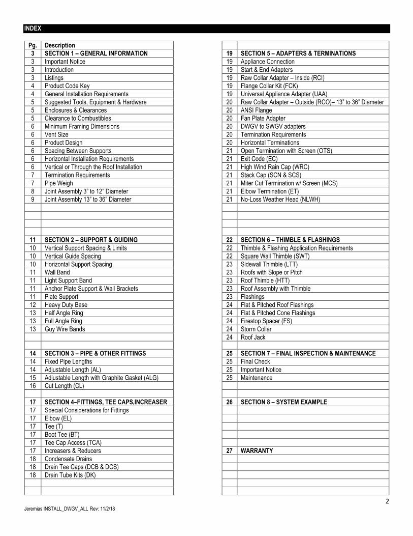
INDEX
Pg. Description
3 SECTION 1 – GENERAL INFORMATION 19 SECTION 5 – ADAPTERS & TERMINATIONS
3 Important Notice 19 Appliance Connection
3 Introduction 19 Start & End Adapters
3 Listings 19 Raw Collar Adapter – Inside (RCI)
4 Product Code Key 19 Flange Collar Kit (FCK)
4 General Installation Requirements 19 Universal Appliance Adapter (UAA)
5 Suggested Tools, Equipment & Hardware 20 Raw Collar Adapter – Outside (RCO)– 13” to 36” Diameter
5 Enclosures & Clearances 20 ANSI Flange
5 Clearance to Combustibles 20 Fan Plate Adapter
6 Minimum Framing Dimensions 20 DWGV to SWGV adapters
6 Vent Size 20 Termination Requirements
6 Product Design 20 Horizontal Terminations
6 Spacing Between Supports 21 Open Termination with Screen (OTS)
6 Horizontal Installation Requirements 21 Exit Code (EC)
6 Vertical or Through the Roof Installation 21 High Wind Rain Cap (WRC)
7 Termination Requirements 21 Stack Cap (SCN & SCS)
7 Pipe Weigh 21 Miter Cut Termination w/ Screen (MCS)
8 Joint Assembly 3” to 12” Diameter 21 Elbow Termination (ET)
9 Joint Assembly 13” to 36” Diameter 21 No-Loss Weather Head (NLWH)
11 SECTION 2 – SUPPORT & GUIDING 22 SECTION 6 – THIMBLE & FLASHINGS
10 Vertical Support Spacing & Limits 22 Thimble & Flashing Application Requirements
10 Vertical Guide Spacing 22 Square Wall Thimble (SWT)
10 Horizontal Support Spacing 23 Sidewall Thimble (LTT)
11 Wall Band 23 Roofs with Slope or Pitch
11 Light Support Band 23 Roof Thimble (HTT)
11 Anchor Plate Support & Wall Brackets 23 Roof Assembly with Thimble
11 Plate Support 23 Flashings
12 Heavy Duty Base 24 Flat & Pitched Roof Flashings
13 Half Angle Ring 24 Flat & Pitched Cone Flashings
13 Full Angle Ring 24 Firestop Spacer (FS)
13 Guy Wire Bands 24 Storm Collar
24 Roof Jack
14 SECTION 3 – PIPE & OTHER FITTINGS 25 SECTION 7 – FINAL INSPECTION & MAINTENANCE
14 Fixed Pipe Lengths 25 Final Check
14 Adjustable Length (AL) 25 Important Notice
15 Adjustable Length with Graphite Gasket (ALG) 25 Maintenance
16 Cut Length (CL)
17 SECTION 4–FITTINGS, TEE CAPS,INCREASER 26 SECTION 8 – SYSTEM EXAMPLE
17 Special Considerations for Fittings
17 Elbow (EL)
17 Tee (T)
17 Boot Tee (BT)
17 Tee Cap Access (TCA)
17 Increasers & Reducers 27 WARRANTY
18 Condensate Drains
18 Drain Tee Caps (DCB & DCS)
18 Drain Tube Kits (DK)
3 Jeremias INSTALL_DWGV_ALL Rev: 11/2/18
SECTION 1 – GENERAL INFORMATION
IMPORTANT: Jeremias Special Gas Vent must be installed by an experienced professional familiar with the operation and maintenance of heating appliances and venting. Failure to follow proper installation procedures as described in these instructions, including joint connections, vent pitch and improper appliance connections may cause unsafe conditions. It is the responsibility of the installer to contact the local authorities having jurisdiction concerning any installation restrictions, including guarding or placement of terminations and/or inspection requirements that may apply. Permits may be required before starting an installation. This product must be installed in accordance with local building code requirements as well as National codes: USA-National Fuel Gas Code ANSI-Z223.1 or NFPA Standard 54, or NFPA 211. In Canada, CAN/CGA-B149.1 or CAN/CGA-149.2 Propane Installation Code as applicable. Compliance with local code, acceptance by the local code authority (AHJ) and warranty coverage is contingent upon the DWGV / SWGV system being installed and maintained in strict accordance with these installation and maintenance instructions. Introduction Jeremias model SWGV and DWGV are factory built stainless steel venting systems for gas fired appliances listed as Category I, II, III and IV, or in Canada, Type BH Gas Venting Systems. The vent joints utilize an external locking band and a Silicone gasket or sealant which provides an easy to install leak free vent system. A full range of fittings & accessories are available to accommodate each application. Model SWGV is Single Wall Gas Vent system and DWGV is the model designation for Double Wall Gas Vent system. Sizes 3-12 have 1” annular airspace and sizes 13-36 have 1.25” airspace. DWGV+1 & DWGV+2 systems have 1”, 1.25”, 2” or 2.25” of fiber insulation respectively. Each model may be intermixed in the same vent system assuming proper clearances and other installation guidelines are maintained for each system. For purposes of these instructions both SWGV & DWGV as well as all variations will be treated together. Differences in UL listings, installation and weights will be shown where needed. Listings SWGV and DWGV are listed to the following Standards: UL-1738 Standard, Venting Systems for Gas-Burning Appliances, Categories II, III and IV - under this Listing and in a category known as “Special Gas Vents”, all variations of Model DWGV and SWGV have been determined suitable for venting Category II, III and IV gas-fired appliances Listed in accordance with certain ANSI gas appliance standards. In this application Model DWGV and SWGV are suitable for use at a temperature not exceeding 550°F (288°C) continuously with maximum internal pressure not exceeding 20” water column (9,000 Pascal) for sizes 3”-12” and up to 90 Inch water column (22,400 Pascal) for sizes 13” – 36” diameter. ULC-S636 (Canadian) Standard for Type BH Gas Venting Systems – under this (c-UL) Listing and in a category known as “Type BH Vents”, all variations of Models DWGV and SWGV have been determined suitable for venting certain gas fired appliances producing flue gas temperatures not exceeding 245°C (473°F) and positive internal pressures not exceeding 9,000 Pascal(20” water column) for sizes 3”-12” and 22,400 Pascals (90 Inch water column) for sizes 13” – 36” diameter. UL-441 Standard, Gas Vents / ULC-S605 (Canadian) Standard for Gas Vents - under these Listings, all variations of Model DWGV have been determined suitable for venting flue gases from gas fired appliances equipped with draft hoods and for venting certain other gas fired appliances specifically Listed for use with Type B Gas Vent.
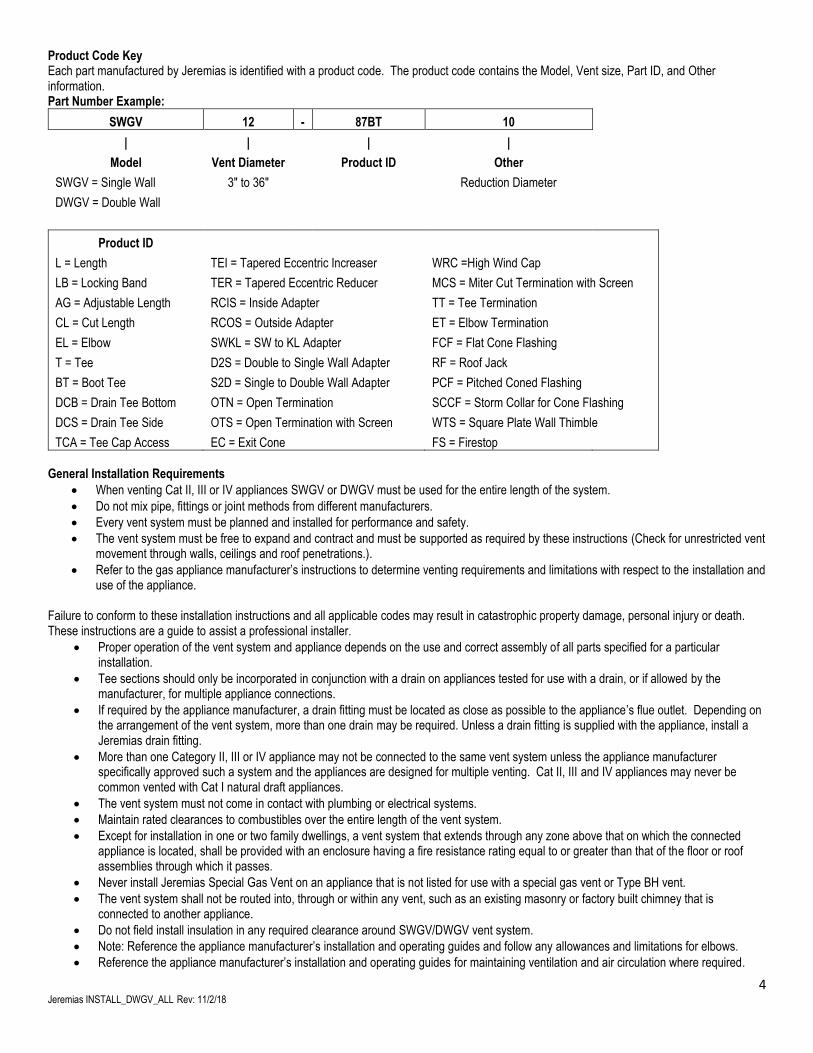
4 Jeremias INSTALL_DWGV_ALL Rev: 11/2/18
Product Code Key Each part manufactured by Jeremias is identified with a product code. The product code contains the Model, Vent size, Part ID, and Other information. Part Number Example:
SWGV 12 - 87BT 10
| | | |
Model Vent Diameter Product ID Other
SWGV = Single Wall 3" to 36" Reduction Diameter
DWGV = Double Wall
Product ID
L = Length TEI = Tapered Eccentric Increaser WRC =High Wind Cap
LB = Locking Band TER = Tapered Eccentric Reducer MCS = Miter Cut Termination with Screen
AG = Adjustable Length RCIS = Inside Adapter TT = Tee Termination
CL = Cut Length RCOS = Outside Adapter ET = Elbow Termination
EL = Elbow SWKL = SW to KL Adapter FCF = Flat Cone Flashing
T = Tee D2S = Double to Single Wall Adapter RF = Roof Jack
BT = Boot Tee S2D = Single to Double Wall Adapter PCF = Pitched Coned Flashing
DCB = Drain Tee Bottom OTN = Open Termination SCCF = Storm Collar for Cone Flashing
DCS = Drain Tee Side OTS = Open Termination with Screen WTS = Square Plate Wall Thimble
TCA = Tee Cap Access EC = Exit Cone FS = Firestop General Installation Requirements
• When venting Cat II, III or IV appliances SWGV or DWGV must be used for the entire length of the system.
• Do not mix pipe, fittings or joint methods from different manufacturers.
• Every vent system must be planned and installed for performance and safety.
• The vent system must be free to expand and contract and must be supported as required by these instructions (Check for unrestricted vent movement through walls, ceilings and roof penetrations.).
• Refer to the gas appliance manufacturer’s instructions to determine venting requirements and limitations with respect to the installation and use of the appliance.
Failure to conform to these installation instructions and all applicable codes may result in catastrophic property damage, personal injury or death. These instructions are a guide to assist a professional installer.
• Proper operation of the vent system and appliance depends on the use and correct assembly of all parts specified for a particular installation.
• Tee sections should only be incorporated in conjunction with a drain on appliances tested for use with a drain, or if allowed by the manufacturer, for multiple appliance connections.
• If required by the appliance manufacturer, a drain fitting must be located as close as possible to the appliance’s flue outlet. Depending on the arrangement of the vent system, more than one drain may be required. Unless a drain fitting is supplied with the appliance, install a Jeremias drain fitting.
• More than one Category II, III or IV appliance may not be connected to the same vent system unless the appliance manufacturer specifically approved such a system and the appliances are designed for multiple venting. Cat II, III and IV appliances may never be common vented with Cat I natural draft appliances.
• The vent system must not come in contact with plumbing or electrical systems.
• Maintain rated clearances to combustibles over the entire length of the vent system.
• Except for installation in one or two family dwellings, a vent system that extends through any zone above that on which the connected appliance is located, shall be provided with an enclosure having a fire resistance rating equal to or greater than that of the floor or roof assemblies through which it passes.
• Never install Jeremias Special Gas Vent on an appliance that is not listed for use with a special gas vent or Type BH vent.
• The vent system shall not be routed into, through or within any vent, such as an existing masonry or factory built chimney that is connected to another appliance.
• Do not field install insulation in any required clearance around SWGV/DWGV vent system.
• Note: Reference the appliance manufacturer’s installation and operating guides and follow any allowances and limitations for elbows.
• Reference the appliance manufacturer’s installation and operating guides for maintaining ventilation and air circulation where required.
5 Jeremias INSTALL_DWGV_ALL Rev: 11/2/18
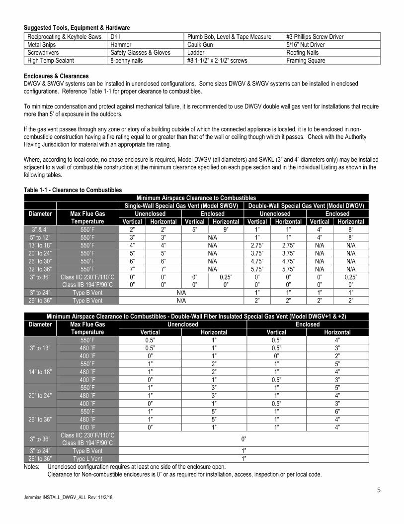
Suggested Tools, Equipment & Hardware
Reciprocating & Keyhole Saws Drill Plumb Bob, Level & Tape Measure #3 Phillips Screw Driver
Metal Snips Hammer Caulk Gun 5/16” Nut Driver
Screwdrivers Safety Glasses & Gloves Ladder Roofing Nails
High Temp Sealant 8-penny nails #8 1-1/2” x 2-1/2” screws Framing Square
Enclosures & Clearances DWGV & SWGV systems can be installed in unenclosed configurations. Some sizes DWGV & SWGV systems can be installed in enclosed configurations. Reference Table 1-1 for proper clearance to combustibles. To minimize condensation and protect against mechanical failure, it is recommended to use DWGV double wall gas vent for installations that require more than 5’ of exposure in the outdoors. If the gas vent passes through any zone or story of a building outside of which the connected appliance is located, it is to be enclosed in non-combustible construction having a fire rating equal to or greater than that of the wall or ceiling though which it passes. Check with the Authority Having Jurisdiction for material with an appropriate fire rating. Where, according to local code, no chase enclosure is required, Model DWGV (all diameters) and SWKL (3” and 4” diameters only) may be installed adjacent to a wall of combustible construction at the minimum clearance specified on each pipe section and in the individual Listing as shown in the following tables. Table 1-1 - Clearance to Combustibles
Minimum Airspace Clearance to Combustibles
Single-Wall Special Gas Vent (Model SWGV) Double-Wall Special Gas Vent (Model DWGV)
Diameter Max Flue Gas Temperature
Unenclosed Enclosed Unenclosed Enclosed
Vertical Horizontal Vertical Horizontal Vertical Horizontal Vertical Horizontal
3” & 4” 550˚F 2” 2” 5” 9” 1” 1” 4” 8”
5” to 12” 550˚F 3” 3” N/A 1” 1” 4” 8”
13” to 18” 550˚F 4” 4” N/A 2.75” 2.75” N/A N/A
20” to 24” 550˚F 5” 5” N/A 3.75” 3.75” N/A N/A
26” to 30” 550˚F 6” 6” N/A 4.75” 4.75” N/A N/A
32” to 36” 550˚F 7” 7” N/A 5.75” 5.75” N/A N/A
3” to 36” Class IIC 230˚F/110˚C Class IIB 194˚F/90˚C
0” 0”
0” 0”
0” 0”
0.25” 0”
0” 0”
0” 0”
0” 0”
0.25” 0”
3” to 24” Type B Vent N/A 1” 1” 1” 1”
26” to 36” Type B Vent N/A 2” 2” 2” 2”
Minimum Airspace Clearance to Combustibles - Double-Wall Fiber Insulated Special Gas Vent (Model DWGV+1 & +2)
Diameter Max Flue Gas Temperature
Unenclosed Enclosed
Vertical Horizontal Vertical Horizontal
3” to 13”
550˚F 0.5” 1” 0.5” 4”
480 ˚F 0.5” 1” 0.5” 3”
400 ˚F 0” 1” 0” 2”
14” to 18”
550˚F 1” 2” 1” 5”
480 ˚F 1” 2” 1” 4”
400 ˚F 0” 1” 0.5” 3”
20” to 24”
550˚F 1” 3” 1” 5”
480 ˚F 1” 3” 1” 4”
400 ˚F 0” 1” 0.5” 3”
26” to 36”
550˚F 1” 5” 1” 6”
480 ˚F 1” 5” 1” 4”
400 ˚F 0” 1” 1” 4”
3” to 36” Class IIC 230˚F/110˚C Class IIB 194˚F/90˚C
0”
3” to 24” Type B Vent 1”
26” to 36” Type L Vent 1”
Notes: Unenclosed configuration requires at least one side of the enclosure open. Clearance for Non-combustible enclosures is 0” or as required for installation, access, inspection or per local code.
6 Jeremias INSTALL_DWGV_ALL Rev: 11/2/18
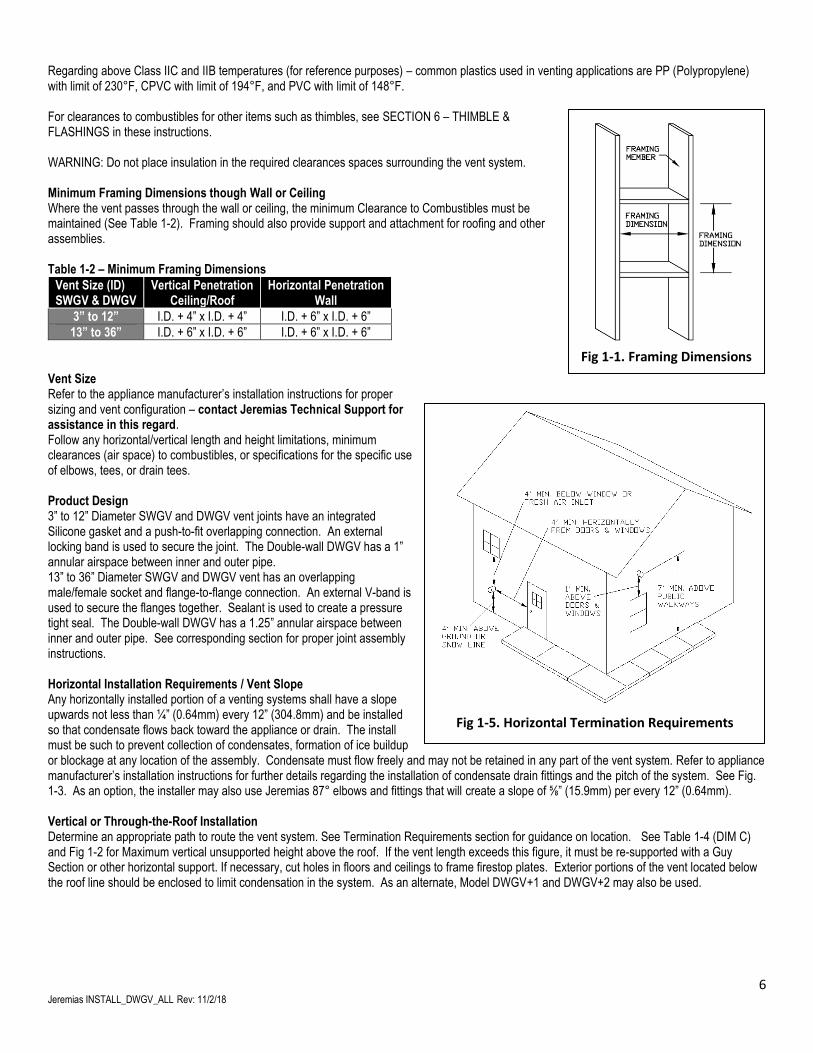
Regarding above Class IIC and IIB temperatures (for reference purposes) – common plastics used in venting applications are PP (Polypropylene) with limit of 230°F, CPVC with limit of 194°F, and PVC with limit of 148°F. For clearances to combustibles for other items such as thimbles, see SECTION 6 – THIMBLE & FLASHINGS in these instructions. WARNING: Do not place insulation in the required clearances spaces surrounding the vent system. Minimum Framing Dimensions though Wall or Ceiling Where the vent passes through the wall or ceiling, the minimum Clearance to Combustibles must be maintained (See Table 1-2). Framing should also provide support and attachment for roofing and other assemblies. Table 1-2 – Minimum Framing Dimensions
Vent Size (ID) SWGV & DWGV
Vertical Penetration Ceiling/Roof
Horizontal Penetration Wall
3” to 12” I.D. + 4” x I.D. + 4” I.D. + 6” x I.D. + 6”
13” to 36” I.D. + 6” x I.D. + 6” I.D. + 6” x I.D. + 6”
Vent Size Refer to the appliance manufacturer’s installation instructions for proper sizing and vent configuration – contact Jeremias Technical Support for assistance in this regard. Follow any horizontal/vertical length and height limitations, minimum clearances (air space) to combustibles, or specifications for the specific use of elbows, tees, or drain tees. Product Design 3” to 12” Diameter SWGV and DWGV vent joints have an integrated Silicone gasket and a push-to-fit overlapping connection. An external locking band is used to secure the joint. The Double-wall DWGV has a 1” annular airspace between inner and outer pipe. 13” to 36” Diameter SWGV and DWGV vent has an overlapping male/female socket and flange-to-flange connection. An external V-band is used to secure the flanges together. Sealant is used to create a pressure tight seal. The Double-wall DWGV has a 1.25” annular airspace between inner and outer pipe. See corresponding section for proper joint assembly instructions. Horizontal Installation Requirements / Vent Slope Any horizontally installed portion of a venting systems shall have a slope upwards not less than ¼” (0.64mm) every 12” (304.8mm) and be installed so that condensate flows back toward the appliance or drain. The install must be such to prevent collection of condensates, formation of ice buildup or blockage at any location of the assembly. Condensate must flow freely and may not be retained in any part of the vent system. Refer to appliance manufacturer’s installation instructions for further details regarding the installation of condensate drain fittings and the pitch of the system. See Fig. 1-3. As an option, the installer may also use Jeremias 87° elbows and fittings that will create a slope of ⅝” (15.9mm) per every 12” (0.64mm). Vertical or Through-the-Roof Installation Determine an appropriate path to route the vent system. See Termination Requirements section for guidance on location. See Table 1-4 (DIM C) and Fig 1-2 for Maximum vertical unsupported height above the roof. If the vent length exceeds this figure, it must be re-supported with a Guy Section or other horizontal support. If necessary, cut holes in floors and ceilings to frame firestop plates. Exterior portions of the vent located below the roof line should be enclosed to limit condensation in the system. As an alternate, Model DWGV+1 and DWGV+2 may also be used.
Fig 1-1. Framing Dimensions
Fig 1-5. Horizontal Termination Requirements
7 Jeremias INSTALL_DWGV_ALL Rev: 11/2/18
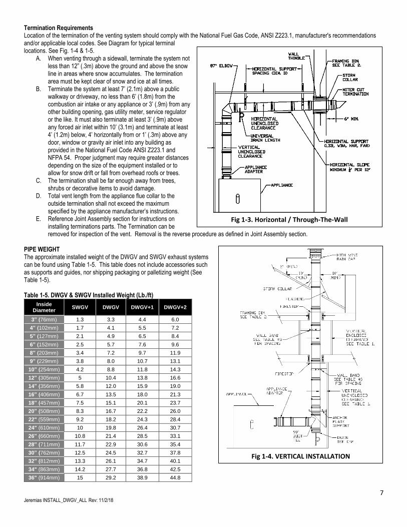
Termination Requirements Location of the termination of the venting system should comply with the National Fuel Gas Code, ANSI Z223.1, manufacturer's recommendations and/or applicable local codes. See Diagram for typical terminal locations. See Fig. 1-4 & 1-5.
A. When venting through a sidewall, terminate the system not less than 12” (.3m) above the ground and above the snow line in areas where snow accumulates. The termination area must be kept clear of snow and ice at all times.
B. Terminate the system at least 7’ (2.1m) above a public walkway or driveway, no less than 6’ (1.8m) from the combustion air intake or any appliance or 3’ (.9m) from any other building opening, gas utility meter, service regulator or the like. It must also terminate at least 3’ (.9m) above any forced air inlet within 10’ (3.1m) and terminate at least 4’ (1.2m) below, 4’ horizontally from or 1’ (.3m) above any door, window or gravity air inlet into any building as provided in the National Fuel Code ANSI Z223.1 and NFPA 54. Proper judgment may require greater distances depending on the size of the equipment installed or to allow for snow drift or fall from overhead roofs or trees.
C. The termination shall be far enough away from trees, shrubs or decorative items to avoid damage.
D. Total vent length from the appliance flue collar to the outside termination shall not exceed the maximum specified by the appliance manufacturer’s instructions.
E. Reference Joint Assembly section for instructions on installing terminations parts. The Termination can be removed for inspection of the vent. Removal is the reverse procedure as defined in Joint Assembly section.
PIPE WEIGHT The approximate installed weight of the DWGV and SWGV exhaust systems can be found using Table 1-5. This table does not include accessories such as supports and guides, nor shipping packaging or palletizing weight (See Table 1-5). Table 1-5. DWGV & SWGV Installed Weight (Lb./ft)
Inside Diameter
SWGV DWGV DWGV+1 DWGV+2
3” (76mm) 1.3 3.3 4.4 6.0
4” (102mm) 1.7 4.1 5.5 7.2
5” (127mm) 2.1 4.9 6.5 8.4
6” (152mm) 2.5 5.7 7.6 9.6
8” (203mm) 3.4 7.2 9.7 11.9
9” (229mm) 3.8 8.0 10.7 13.1
10” (254mm) 4.2 8.8 11.8 14.3
12” (305mm) 5 10.4 13.8 16.6
14” (356mm) 5.8 12.0 15.9 19.0
16” (406mm) 6.7 13.5 18.0 21.3
18” (457mm) 7.5 15.1 20.1 23.7
20” (508mm) 8.3 16.7 22.2 26.0
22" (559mm) 9.2 18.2 24.3 28.4
24" (610mm) 10 19.8 26.4 30.7
26” (660mm) 10.8 21.4 28.5 33.1
28” (711mm) 11.7 22.9 30.6 35.4
30” (762mm) 12.5 24.5 32.7 37.8
32” (812mm) 13.3 26.1 34.7 40.1
34" (863mm) 14.2 27.7 36.8 42.5
36" (914mm) 15 29.2 38.9 44.8
Fig 1-3. Horizontal / Through-The-Wall
Fig 1-4. VERTICAL INSTALLATION
8 Jeremias INSTALL_DWGV_ALL Rev: 11/2/18
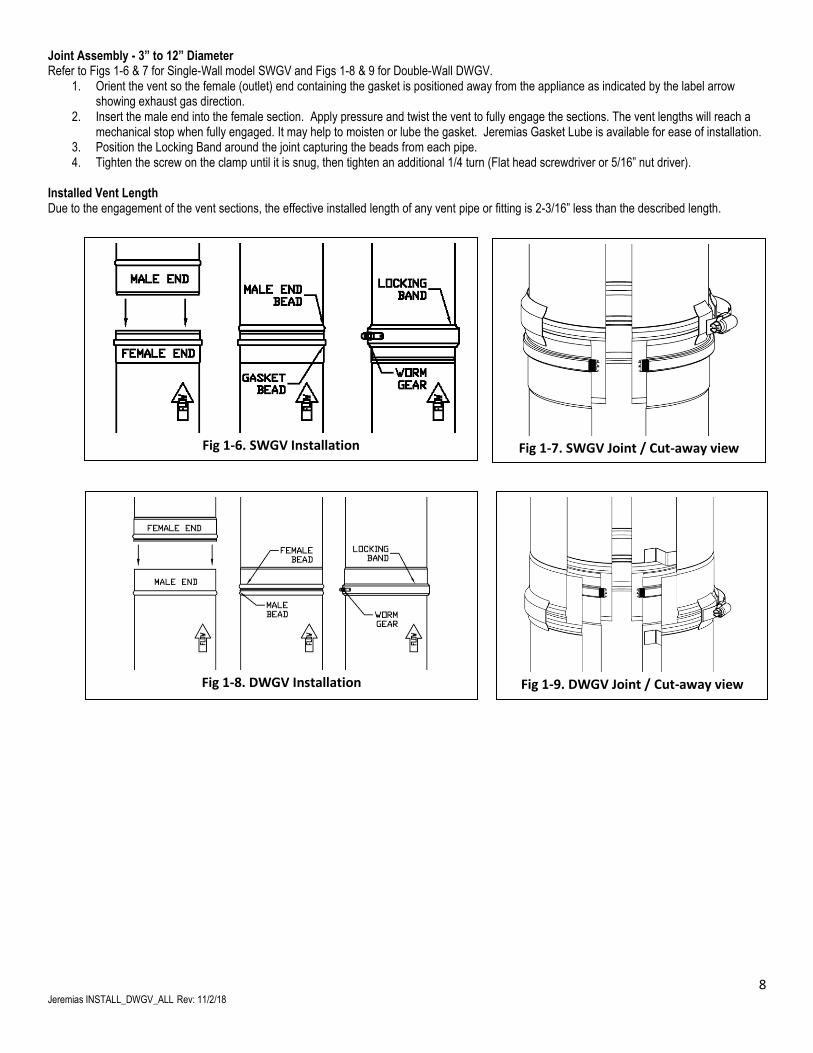
Joint Assembly - 3” to 12” Diameter Refer to Figs 1-6 & 7 for Single-Wall model SWGV and Figs 1-8 & 9 for Double-Wall DWGV.
1. Orient the vent so the female (outlet) end containing the gasket is positioned away from the appliance as indicated by the label arrow showing exhaust gas direction.
2. Insert the male end into the female section. Apply pressure and twist the vent to fully engage the sections. The vent lengths will reach a mechanical stop when fully engaged. It may help to moisten or lube the gasket. Jeremias Gasket Lube is available for ease of installation.
3. Position the Locking Band around the joint capturing the beads from each pipe. 4. Tighten the screw on the clamp until it is snug, then tighten an additional 1/4 turn (Flat head screwdriver or 5/16” nut driver).
Installed Vent Length Due to the engagement of the vent sections, the effective installed length of any vent pipe or fitting is 2-3/16” less than the described length.
Fig 1-6. SWGV Installation
Fig 1-8. DWGV Installation
Fig 1-9. DWGV Joint / Cut-away view
Fig 1-7. SWGV Joint / Cut-away view
9 Jeremias INSTALL_DWGV_ALL Rev: 11/2/18
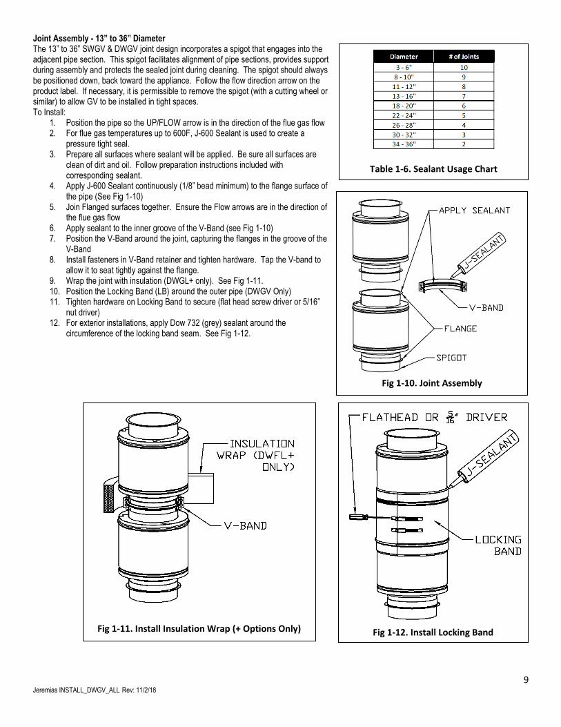
Joint Assembly - 13” to 36” Diameter The 13” to 36” SWGV & DWGV joint design incorporates a spigot that engages into the adjacent pipe section. This spigot facilitates alignment of pipe sections, provides support during assembly and protects the sealed joint during cleaning. The spigot should always be positioned down, back toward the appliance. Follow the flow direction arrow on the product label. If necessary, it is permissible to remove the spigot (with a cutting wheel or similar) to allow GV to be installed in tight spaces. To Install:
1. Position the pipe so the UP/FLOW arrow is in the direction of the flue gas flow 2. For flue gas temperatures up to 600F, J-600 Sealant is used to create a
pressure tight seal. 3. Prepare all surfaces where sealant will be applied. Be sure all surfaces are
clean of dirt and oil. Follow preparation instructions included with corresponding sealant.
4. Apply J-600 Sealant continuously (1/8” bead minimum) to the flange surface of the pipe (See Fig 1-10)
5. Join Flanged surfaces together. Ensure the Flow arrows are in the direction of the flue gas flow
6. Apply sealant to the inner groove of the V-Band (see Fig 1-10) 7. Position the V-Band around the joint, capturing the flanges in the groove of the
V-Band 8. Install fasteners in V-Band retainer and tighten hardware. Tap the V-band to
allow it to seat tightly against the flange. 9. Wrap the joint with insulation (DWGL+ only). See Fig 1-11. 10. Position the Locking Band (LB) around the outer pipe (DWGV Only) 11. Tighten hardware on Locking Band to secure (flat head screw driver or 5/16”
nut driver) 12. For exterior installations, apply Dow 732 (grey) sealant around the
circumference of the locking band seam. See Fig 1-12.
Fig 1-10. Joint Assembly
Fig 1-11. Install Insulation Wrap (+ Options Only)
Table 1-6. Sealant Usage Chart
Number of Joints sealed per tube.
Fig 1-12. Install Locking Band
10 Jeremias INSTALL_DWGV_ALL Rev: 11/2/18
SECTION 2 – SUPPORT & GUIDING
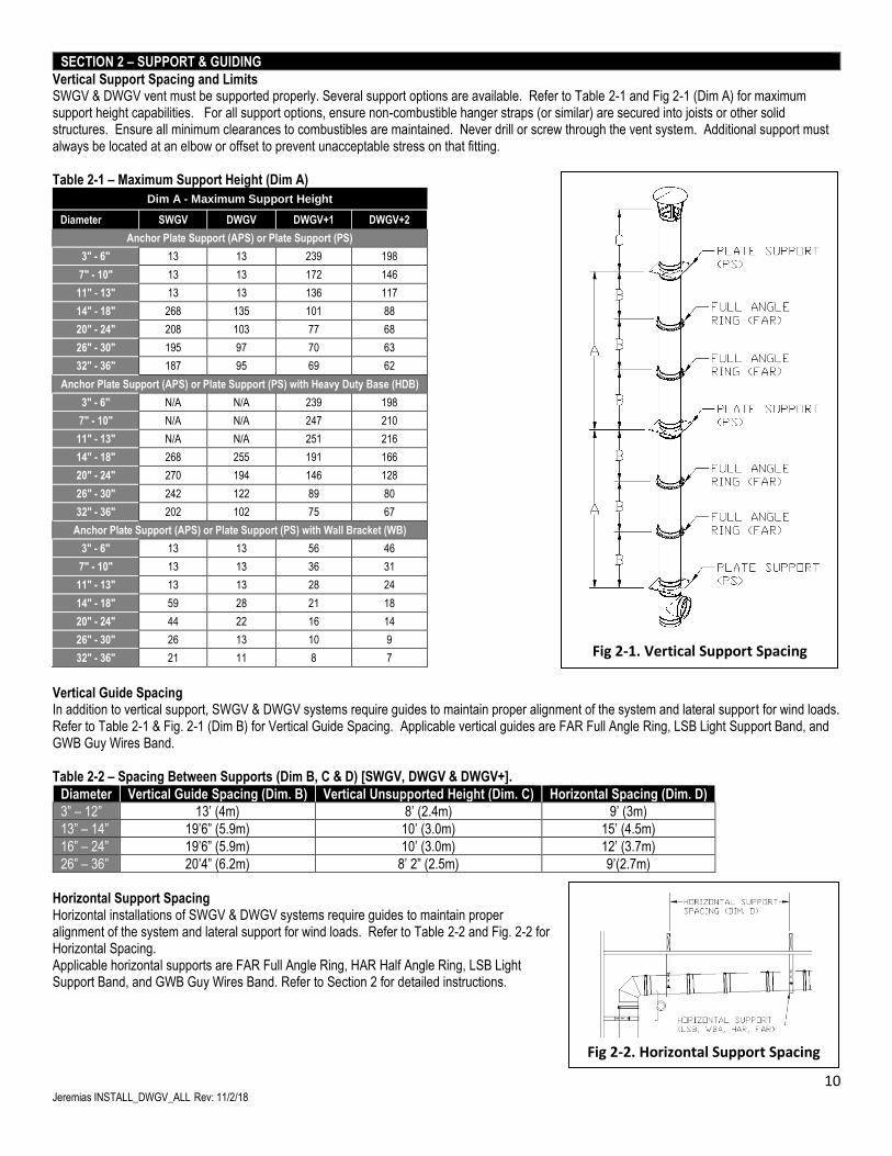
Vertical Support Spacing and Limits SWGV & DWGV vent must be supported properly. Several support options are available. Refer to Table 2-1 and Fig 2-1 (Dim A) for maximum support height capabilities. For all support options, ensure non-combustible hanger straps (or similar) are secured into joists or other solid structures. Ensure all minimum clearances to combustibles are maintained. Never drill or screw through the vent system. Additional support must always be located at an elbow or offset to prevent unacceptable stress on that fitting. Table 2-1 – Maximum Support Height (Dim A)
Dim A - Maximum Support Height
Diameter SWGV DWGV DWGV+1 DWGV+2
Anchor Plate Support (APS) or Plate Support (PS)
3" - 6" 13 13 239 198
7" - 10" 13 13 172 146
11" - 13" 13 13 136 117
14" - 18" 268 135 101 88
20" - 24" 208 103 77 68
26" - 30" 195 97 70 63
32" - 36" 187 95 69 62
Anchor Plate Support (APS) or Plate Support (PS) with Heavy Duty Base (HDB)
3" - 6" N/A N/A 239 198
7" - 10" N/A N/A 247 210
11" - 13" N/A N/A 251 216
14" - 18" 268 255 191 166
20" - 24" 270 194 146 128
26" - 30" 242 122 89 80
32" - 36" 202 102 75 67
Anchor Plate Support (APS) or Plate Support (PS) with Wall Bracket (WB)
3" - 6" 13 13 56 46
7" - 10" 13 13 36 31
11" - 13" 13 13 28 24
14" - 18" 59 28 21 18
20" - 24" 44 22 16 14
26" - 30" 26 13 10 9
32" - 36" 21 11 8 7
Vertical Guide Spacing In addition to vertical support, SWGV & DWGV systems require guides to maintain proper alignment of the system and lateral support for wind loads. Refer to Table 2-1 & Fig. 2-1 (Dim B) for Vertical Guide Spacing. Applicable vertical guides are FAR Full Angle Ring, LSB Light Support Band, and GWB Guy Wires Band. Table 2-2 – Spacing Between Supports (Dim B, C & D) [SWGV, DWGV & DWGV+].
Diameter Vertical Guide Spacing (Dim. B) Vertical Unsupported Height (Dim. C) Horizontal Spacing (Dim. D)
3” – 12” 13’ (4m) 8’ (2.4m) 9’ (3m)
13” – 14” 19’6” (5.9m) 10’ (3.0m) 15’ (4.5m)
16” – 24” 19’6” (5.9m) 10’ (3.0m) 12’ (3.7m)
26” – 36” 20’4” (6.2m) 8’ 2” (2.5m) 9’(2.7m)
Horizontal Support Spacing Horizontal installations of SWGV & DWGV systems require guides to maintain proper alignment of the system and lateral support for wind loads. Refer to Table 2-2 and Fig. 2-2 for Horizontal Spacing. Applicable horizontal supports are FAR Full Angle Ring, HAR Half Angle Ring, LSB Light Support Band, and GWB Guy Wires Band. Refer to Section 2 for detailed instructions.
Fig 2-1. Vertical Support Spacing
Fig 2-2. Horizontal Support Spacing
11 Jeremias INSTALL_DWGV_ALL Rev: 11/2/18
Wall Band (WBA) [Size 3” to 12” Diameter Only] The Wall Band is used to provide vertical or horizontal support. Refer to Table 1-4 for required minimum spacing. To Install (See Fig 2-1):
1. Secure mounting bracket to joist or suitable solid structure with 5/8” lag bolts. 2. Route vent through clamp band and secure by tightening Clamp Band Bolts.
Light Support Band (LSB) The LSB provides a means to suspend the vent from rods or cables. To Install (See Fig 2-2):
1. Secure band around vent and tighten Clamp Band Bolts. 2. Attach cable or rods (supplied by installer) to Flanges of Clamp bands and secure to solid
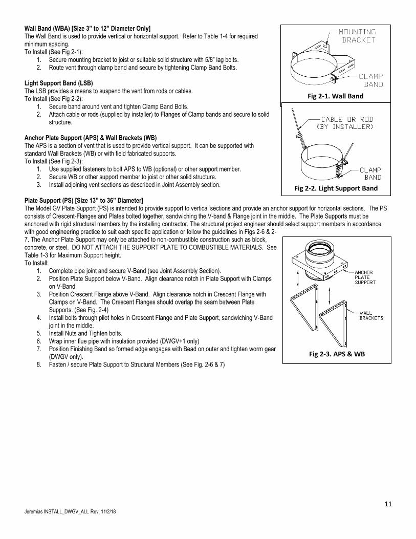
structure. Anchor Plate Support (APS) & Wall Brackets (WB) The APS is a section of vent that is used to provide vertical support. It can be supported with standard Wall Brackets (WB) or with field fabricated supports. To Install (See Fig 2-3):
1. Use supplied fasteners to bolt APS to WB (optional) or other support member. 2. Secure WB or other support member to joist or other solid structure. 3. Install adjoining vent sections as described in Joint Assembly section.
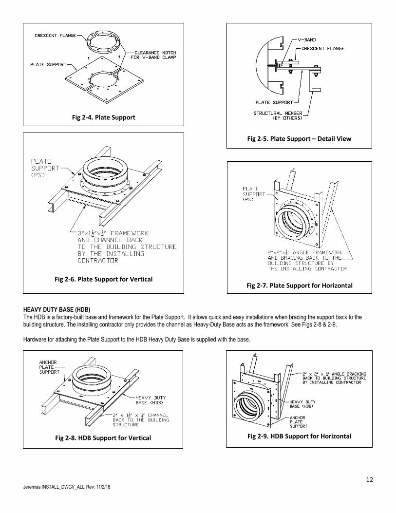
Plate Support (PS) [Size 13” to 36” Diameter] The Model GV Plate Support (PS) is intended to provide support to vertical sections and provide an anchor support for horizontal sections. The PS consists of Crescent-Flanges and Plates bolted together, sandwiching the V-band & Flange joint in the middle. The Plate Supports must be anchored with rigid structural members by the installing contractor. The structural project engineer should select support members in accordance with good engineering practice to suit each specific application or follow the guidelines in Figs 2-6 & 2-7. The Anchor Plate Support may only be attached to non-combustible construction such as block, concrete, or steel. DO NOT ATTACH THE SUPPORT PLATE TO COMBUSTIBLE MATERIALS. See Table 1-3 for Maximum Support height. To Install:
1. Complete pipe joint and secure V-Band (see Joint Assembly Section). 2. Position Plate Support below V-Band. Align clearance notch in Plate Support with Clamps
on V-Band 3. Position Crescent Flange above V-Band. Align clearance notch in Crescent Flange with
Clamps on V-Band. The Crescent Flanges should overlap the seam between Plate Supports. (See Fig. 2-4)
4. Install bolts through pilot holes in Crescent Flange and Plate Support, sandwiching V-Band joint in the middle.
5. Install Nuts and Tighten bolts. 6. Wrap inner flue pipe with insulation provided (DWGV+1 only) 7. Position Finishing Band so formed edge engages with Bead on outer and tighten worm gear
(DWGV only). 8. Fasten / secure Plate Support to Structural Members (See Fig. 2-6 & 7)
Fig 2-1. Wall Band
Fig 2-3. APS & WB
Fig 2-2. Light Support Band
12 Jeremias INSTALL_DWGV_ALL Rev: 11/2/18
HEAVY DUTY BASE (HDB) The HDB is a factory-built base and framework for the Plate Support. It allows quick and easy installations when bracing the support back to the building structure. The installing contractor only provides the channel as Heavy-Duty Base acts as the framework. See Figs 2-8 & 2-9. Hardware for attaching the Plate Support to the HDB Heavy Duty Base is supplied with the base.
Fig 2-4. Plate Support
Fig 2-5. Plate Support – Detail View
Fig 2-6. Plate Support for Vertical
Fig 2-7. Plate Support for Horizontal
Fig 2-8. HDB Support for Vertical
Fig 2-9. HDB Support for Horizontal
13 Jeremias INSTALL_DWGV_ALL Rev: 11/2/18
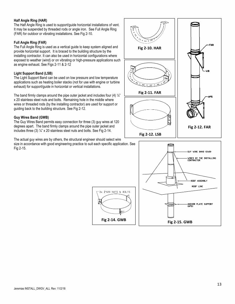
Half Angle Ring (HAR) The Half Angle Ring is used to support/guide horizontal installations of vent. It may be suspended by threaded rods or angle iron. See Full Angle Ring (FAR) for outdoor or vibrating installations. See Fig 2-10. Full Angle Ring (FAR) The Full Angle Ring is used as a vertical guide to keep system aligned and provide horizontal support. It is braced to the building structure by the installing contractor. It can also be used in horizontal configurations where exposed to weather (wind) or on vibrating or high-pressure applications such as engine exhaust. See Figs 2-11 & 2-12 Light Support Band (LSB) The Light Support Band can be used on low pressure and low temperature applications such as heating boiler stacks (not for use with engine or turbine exhaust) for support/guide in horizontal or vertical installations. The band firmly clamps around the pipe outer jacket and includes four (4) ¼” x 20 stainless steel nuts and bolts. Remaining hole in the middle where wires or threaded rods (by the installing contractor) are used for support or guiding back to the building structure. See Fig 2-12. Guy Wires Band (GWB) The Guy Wires Band permits easy connection for three (3) guy wires at 120 degrees apart. The band firmly clamps around the pipe outer jacket and includes three (3) ¼” x 20 stainless steel nuts and bolts. See Fig 2-14. The actual guy wires are by others, the structural engineer should select wire size in accordance with good engineering practice to suit each specific application. See Fig 2-15.
Fig 2-10. HAR
Fig 2-11. FAR
Fig 2-12. FAR
Fig 2-12. LSB
Fig 2-14. GWB Fig 2-15. GWB
14 Jeremias INSTALL_DWGV_ALL Rev: 11/2/18
SECTION 3 – PIPE & OTHER LENGTHS
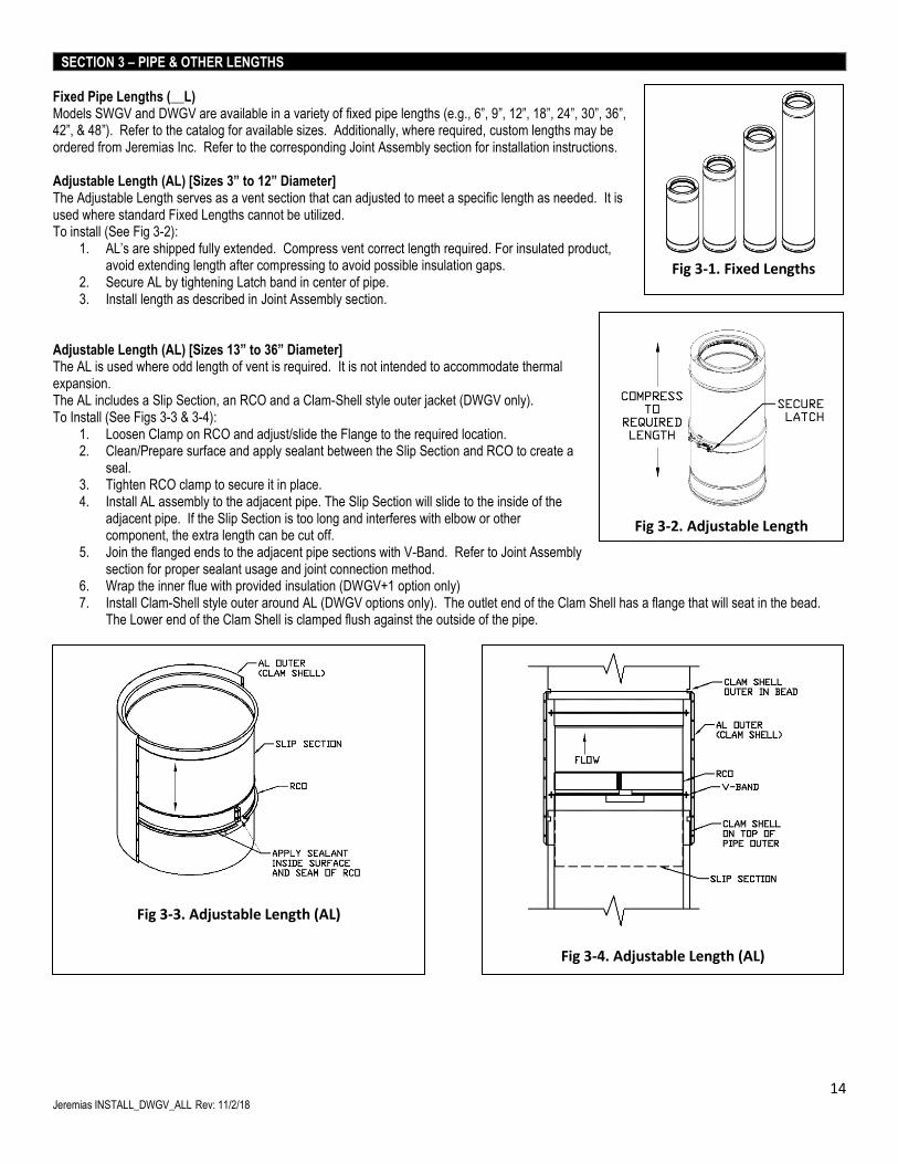
Fixed Pipe Lengths (__L) Models SWGV and DWGV are available in a variety of fixed pipe lengths (e.g., 6”, 9”, 12”, 18”, 24”, 30”, 36”, 42”, & 48”). Refer to the catalog for available sizes. Additionally, where required, custom lengths may be ordered from Jeremias Inc. Refer to the corresponding Joint Assembly section for installation instructions. Adjustable Length (AL) [Sizes 3” to 12” Diameter] The Adjustable Length serves as a vent section that can adjusted to meet a specific length as needed. It is used where standard Fixed Lengths cannot be utilized. To install (See Fig 3-2):
1. AL’s are shipped fully extended. Compress vent correct length required. For insulated product, avoid extending length after compressing to avoid possible insulation gaps.
2. Secure AL by tightening Latch band in center of pipe. 3. Install length as described in Joint Assembly section.
Adjustable Length (AL) [Sizes 13” to 36” Diameter] The AL is used where odd length of vent is required. It is not intended to accommodate thermal expansion. The AL includes a Slip Section, an RCO and a Clam-Shell style outer jacket (DWGV only). To Install (See Figs 3-3 & 3-4):
1. Loosen Clamp on RCO and adjust/slide the Flange to the required location. 2. Clean/Prepare surface and apply sealant between the Slip Section and RCO to create a
seal. 3. Tighten RCO clamp to secure it in place. 4. Install AL assembly to the adjacent pipe. The Slip Section will slide to the inside of the
adjacent pipe. If the Slip Section is too long and interferes with elbow or other component, the extra length can be cut off.
5. Join the flanged ends to the adjacent pipe sections with V-Band. Refer to Joint Assembly section for proper sealant usage and joint connection method.
6. Wrap the inner flue with provided insulation (DWGV+1 option only) 7. Install Clam-Shell style outer around AL (DWGV options only). The outlet end of the Clam Shell has a flange that will seat in the bead.
The Lower end of the Clam Shell is clamped flush against the outside of the pipe.
Fig 3-2. Adjustable Length
Fig 3-3. Adjustable Length (AL)
Fig 3-4. Adjustable Length (AL)
Fig 3-1. Fixed Lengths
15 Jeremias INSTALL_DWGV_ALL Rev: 11/2/18
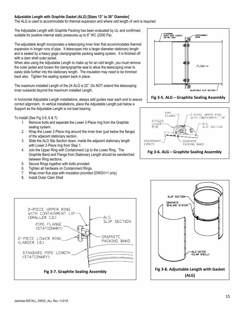
Adjustable Length with Graphite Gasket (ALG) [Sizes 13” to 36” Diameter] The ALG is used to accommodate for thermal expansion and where odd length of vent is required. The Adjustable Length with Graphite Packing has been evaluated by UL and confirmed suitable for positive internal static pressures up to 8” WC (2000 Pa). The adjustable length incorporates a telescoping inner liner that accommodates thermal expansion in longer runs of pipe. It telescopes into a larger diameter stationary length and is sealed by a heavy gage clamp/graphite packing sealing system. It is finished off with a clam shell outer jacket. When also using the Adjustable Length to make up for an odd length, you must remove the outer jacket and loosen the clamp/graphite seal to allow the telescoping inner to easily slide further into the stationary length. The insulation may need to be trimmed back also. Tighten the sealing system back in place. The maximum installed Length of the 24 ALG is 22”. Do NOT extend the telescoping inner outwards beyond the maximum installed Length. In horizontal Adjustable Length installations, always add guides near each end to assure correct alignment. In vertical installations, place the Adjustable Length just below a Support as the Adjustable Length is not load bearing. To Install (See Fig 3-5, 6 & 7):
1. Remove bolts and separate the Lower 2-Piece ring from the Graphite sealing system.
2. Wrap the Lower 2-Piece ring around the inner liner (just below the flange) of the adjacent stationary section.
3. Slide the ALG Slip Section down, inside the adjacent stationary length with Lower 2-Piece ring from Step 1.
4. Join the Upper Ring with Containment Lip to the Lower Ring. The Graphite Band and Flange from Stationary Length should be sandwiched between Ring sections.
5. Secure Rings together with bolts provided 6. Tighten all hardware on Containment Rings. 7. Wrap inner flue pipe with insulation provided (DWGV+1 only) 8. Install Outer Clam Shell
Fig 3-8. Adjustable Length with Gasket
(ALG)
Fig 3-6. ALG – Graphite Sealing Assembly
Fig 3-5. ALG – Graphite Sealing Assembly
Fig 3-7. Graphite Sealing Assembly
16 Jeremias INSTALL_DWGV_ALL Rev: 11/2/18
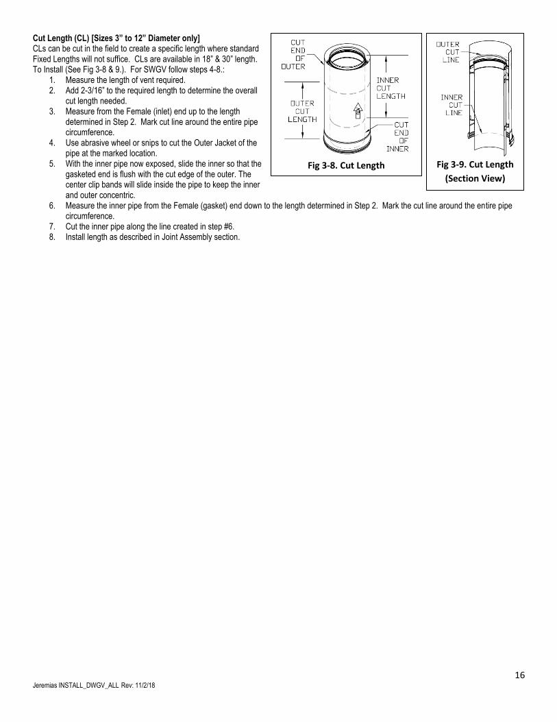
Cut Length (CL) [Sizes 3” to 12” Diameter only] CLs can be cut in the field to create a specific length where standard Fixed Lengths will not suffice. CLs are available in 18” & 30” length. To Install (See Fig 3-8 & 9.). For SWGV follow steps 4-8.:
1. Measure the length of vent required. 2. Add 2-3/16” to the required length to determine the overall
cut length needed. 3. Measure from the Female (inlet) end up to the length
determined in Step 2. Mark cut line around the entire pipe circumference.
4. Use abrasive wheel or snips to cut the Outer Jacket of the pipe at the marked location.
5. With the inner pipe now exposed, slide the inner so that the gasketed end is flush with the cut edge of the outer. The center clip bands will slide inside the pipe to keep the inner and outer concentric.
6. Measure the inner pipe from the Female (gasket) end down to the length determined in Step 2. Mark the cut line around the entire pipe circumference.
7. Cut the inner pipe along the line created in step #6. 8. Install length as described in Joint Assembly section.
Fig 3-9. Cut Length
(Section View)
Fig 3-8. Cut Length
17 Jeremias INSTALL_DWGV_ALL Rev: 11/2/18
SECTION 4 – FITTINGS, TEE CAPS & INCREASERS
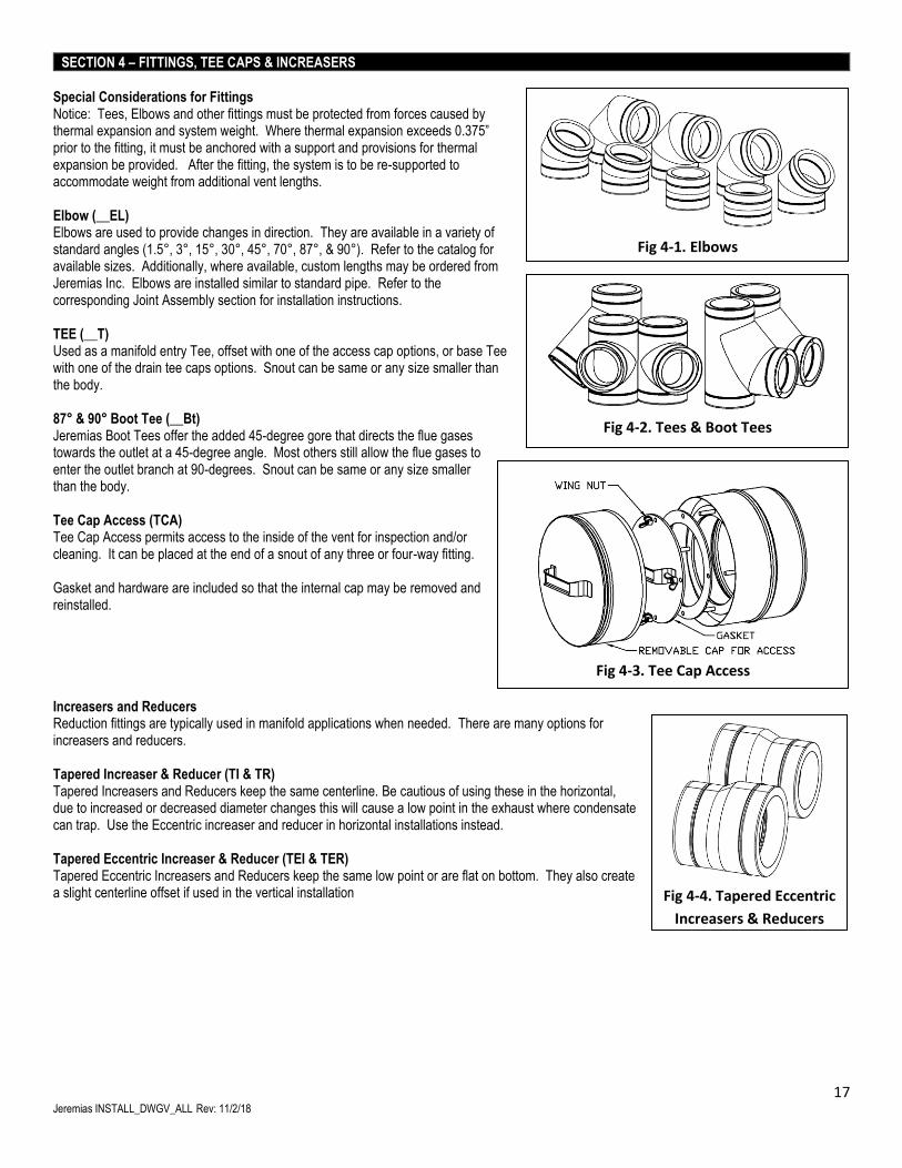
Special Considerations for Fittings Notice: Tees, Elbows and other fittings must be protected from forces caused by thermal expansion and system weight. Where thermal expansion exceeds 0.375” prior to the fitting, it must be anchored with a support and provisions for thermal expansion be provided. After the fitting, the system is to be re-supported to accommodate weight from additional vent lengths. Elbow (__EL) Elbows are used to provide changes in direction. They are available in a variety of standard angles (1.5°, 3°, 15°, 30°, 45°, 70°, 87°, & 90°). Refer to the catalog for available sizes. Additionally, where available, custom lengths may be ordered from Jeremias Inc. Elbows are installed similar to standard pipe. Refer to the corresponding Joint Assembly section for installation instructions. TEE (__T) Used as a manifold entry Tee, offset with one of the access cap options, or base Tee with one of the drain tee caps options. Snout can be same or any size smaller than the body. 87° & 90° Boot Tee (__Bt) Jeremias Boot Tees offer the added 45-degree gore that directs the flue gases towards the outlet at a 45-degree angle. Most others still allow the flue gases to enter the outlet branch at 90-degrees. Snout can be same or any size smaller than the body. Tee Cap Access (TCA) Tee Cap Access permits access to the inside of the vent for inspection and/or cleaning. It can be placed at the end of a snout of any three or four-way fitting. Gasket and hardware are included so that the internal cap may be removed and reinstalled. Increasers and Reducers Reduction fittings are typically used in manifold applications when needed. There are many options for increasers and reducers. Tapered Increaser & Reducer (TI & TR) Tapered Increasers and Reducers keep the same centerline. Be cautious of using these in the horizontal, due to increased or decreased diameter changes this will cause a low point in the exhaust where condensate can trap. Use the Eccentric increaser and reducer in horizontal installations instead. Tapered Eccentric Increaser & Reducer (TEI & TER) Tapered Eccentric Increasers and Reducers keep the same low point or are flat on bottom. They also create a slight centerline offset if used in the vertical installation
Fig 4-1. Elbows
Fig 4-2. Tees & Boot Tees
Fig 4-3. Tee Cap Access
Fig 4-4. Tapered Eccentric
Increasers & Reducers
18 Jeremias INSTALL_DWGV_ALL Rev: 11/2/18
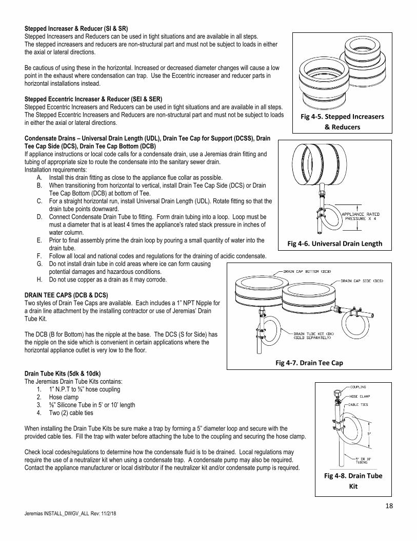
Stepped Increaser & Reducer (SI & SR) Stepped Increasers and Reducers can be used in tight situations and are available in all steps. The stepped increasers and reducers are non-structural part and must not be subject to loads in either the axial or lateral directions. Be cautious of using these in the horizontal. Increased or decreased diameter changes will cause a low point in the exhaust where condensation can trap. Use the Eccentric increaser and reducer parts in horizontal installations instead. Stepped Eccentric Increaser & Reducer (SEI & SER) Stepped Eccentric Increasers and Reducers can be used in tight situations and are available in all steps. The Stepped Eccentric Increasers and Reducers are non-structural part and must not be subject to loads in either the axial or lateral directions. Condensate Drains – Universal Drain Length (UDL), Drain Tee Cap for Support (DCSS), Drain Tee Cap Side (DCS), Drain Tee Cap Bottom (DCB) If appliance instructions or local code calls for a condensate drain, use a Jeremias drain fitting and tubing of appropriate size to route the condensate into the sanitary sewer drain. Installation requirements:
A. Install this drain fitting as close to the appliance flue collar as possible. B. When transitioning from horizontal to vertical, install Drain Tee Cap Side (DCS) or Drain
Tee Cap Bottom (DCB) at bottom of Tee. C. For a straight horizontal run, install Universal Drain Length (UDL). Rotate fitting so that the
drain tube points downward. D. Connect Condensate Drain Tube to fitting. Form drain tubing into a loop. Loop must be
must a diameter that is at least 4 times the appliance's rated stack pressure in inches of water column.
E. Prior to final assembly prime the drain loop by pouring a small quantity of water into the drain tube.
F. Follow all local and national codes and regulations for the draining of acidic condensate. G. Do not install drain tube in cold areas where ice can form causing
potential damages and hazardous conditions. H. Do not use copper as a drain as it may corrode.
DRAIN TEE CAPS (DCB & DCS) Two styles of Drain Tee Caps are available. Each includes a 1” NPT Nipple for a drain line attachment by the installing contractor or use of Jeremias’ Drain Tube Kit. The DCB (B for Bottom) has the nipple at the base. The DCS (S for Side) has the nipple on the side which is convenient in certain applications where the horizontal appliance outlet is very low to the floor. Drain Tube Kits (5dk & 10dk) The Jeremias Drain Tube Kits contains:
1. 1” N.P.T to ⅝” hose coupling 2. Hose clamp 3. ⅝” Silicone Tube in 5’ or 10’ length 4. Two (2) cable ties
When installing the Drain Tube Kits be sure make a trap by forming a 5” diameter loop and secure with the provided cable ties. Fill the trap with water before attaching the tube to the coupling and securing the hose clamp. Check local codes/regulations to determine how the condensate fluid is to be drained. Local regulations may require the use of a neutralizer kit when using a condensate trap. A condensate pump may also be required. Contact the appliance manufacturer or local distributor if the neutralizer kit and/or condensate pump is required.
Fig 4-6. Universal Drain Length
Fig 4-5. Stepped Increasers
& Reducers
Fig 4-8. Drain Tube
Kit
Fig 4-7. Drain Tee Cap
19 Jeremias INSTALL_DWGV_ALL Rev: 11/2/18
SECTION 5 – ADAPTERS & TERMINATIONS
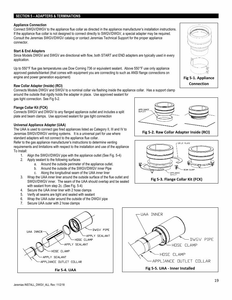
Appliance Connection Connect SWGV/DWGV to the appliance flue collar as directed in the appliance manufacturer’s installation instructions. If the appliance flue collar is not designed to connect directly to SWGV/DWGV, a special adapter may be required. Consult the Jeremias SWGV/DWGV catalog or contact Jeremias Technical Support for the proper appliance connector. Start & End Adapters Since Models DWGV and SWGV are directional with flow, both START and END adapters are typically used in every application. Up to 550°F flue gas temperatures use Dow Corning 736 or equivalent sealant. Above 550°F use only appliance approved gaskets/blanket (that comes with equipment you are connecting to such as ANSI flange connections on engine and power generation equipment) Raw Collar Adapter (Inside) (RCI) Connects Models DWGV and SWGV to a nominal collar via flashing inside the appliance collar. Has a support clamp around the outside that rigidly holds the adapter in place. Use approved sealant for gas tight connection. See Fig 5-2. Flange Collar Kit (FCK) Connects SWGV and DWGV to any flanged appliance outlet and includes a split plate and beam clamps. Use approved sealant for gas tight connection Universal Appliance Adapter (UAA) The UAA is used to connect gas fired appliances listed as Category II, III and IV to Jeremias SWGV/DWGV venting systems. It is a universal part for use where standard adapters will not connect to the appliance flue collar. Refer to the gas appliance manufacturer’s instructions to determine venting requirements and limitations with respect to the installation and use of the appliance To Install:
1. Align the SWGV/DWGV pipe with the appliance outlet (See Fig. 5-4) 2. Apply sealant to the following surfaces
a. Around the outside perimeter of the appliance outlet. b. Around the outside of the SWGV/DWGV inner Pipe c. Along the longitudinal seam of the UAA inner liner
3. Wrap the UAA inner liner around the outside surface of the flue outlet and SWGV/DWGV inner. The seam of the UAA should overlap and be sealed with sealant from step 2c. (See Fig. 5-4)
4. Secure the UAA inner liner with 2 hose clamps 5. Verify all seams are tight and sealed with sealant 6. Wrap the UAA outer around the outside of the DWGV pipe 7. Secure UAA outer with 2 hose clamps
Fig 5-1. Appliance
Connection
Fig 5-4. UAA
Fig 5-5. UAA - Inner Installed
Fig 5-2. Raw Collar Adapter Inside (RCI)
Fig 5-3. Flange Collar Kit (FCK)
20 Jeremias INSTALL_DWGV_ALL Rev: 11/2/18
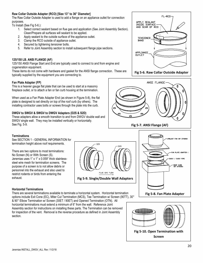
Raw Collar Outside Adapter (RCO) [Size 13” to 36” Diameter] The Raw Collar Outside Adapter is used to add a flange on an appliance outlet for connection purposes. To Install (See Fig 5-6.):
1. Select correct sealant based on flue gas and application (See Joint Assembly Section). Clean/Prepare all surfaces will sealant to be applied.
2. Apply sealant to the outside surface of the appliance outlet. 3. Clamp the RCO outside of appliance outlet. 4. Secured by tightening tensioner bolts. 5. Refer to Joint Assembly section to install subsequent flange pipe sections.
125/150 LB. ANSI FLANGE (AF) 125/150 ANSI Flange Start and End are typically used to connect to and from engine and cogeneration equipment. These items do not come with hardware and gasket for the ANSI flange connection. These are typically supplied by the equipment you are connecting to. Fan Plate Adapter (FP) This is a heavier gauge flat plate that can be used to start at a masonry fireplace outlet, or to attach a fan or fan curb housing at the termination. When used as a Fan Plate Adapter End (as shown in Figure 5-8), the flat plate is designed to set directly on top of the roof curb (by others). The installing contractor uses bolts or screws through the plate into the curb. DWGV to SWGV & SWGV to DWGV Adapters (D2S & S2D) These adapters allow a smooth transition to and from DWGV double wall and SWGV single wall. They may be installed vertically or horizontally. See Fig. 5-9. Terminations See SECTION 1 - GENERAL INFORMATION for termination height above roof requirements. There are two options to most terminations: No Screen (N) or With Screen (S). Jeremias uses 1” x 1” x 0.059” thick stainless-steel wire mesh for termination screens. The purpose of a screen is to not allow debris or personnel into the exhaust and also used to restrict rodents or birds from entering the exhaust. Horizontal Terminations There are several terminations available to terminate a horizontal system. Horizontal termination options include Exit Cone (EC), Miter Cut Termination (MCS), Tee Termination w/ Screen (90TT), 30° & 90° Elbow Termination w/ Screen (30ET / 90ET) and Opened Termination (OTN). All horizontal terminations must extend a minimum of 6” from the wall. Reference Joint Assembly section for instructions on installing these parts. The Termination can be removed for inspection of the vent. Removal is the reverse procedure as defined in Joint Assembly section.
Fig 5-6. Raw Collar Outside Adapter
Fig 5-7. ANSI Flange (AF)
Fig 5-8. Fan Plate Adapter
Fig 5-9. Single/Double Wall Adapters
Fig 5-10. Open Termination with
Screen
21 Jeremias INSTALL_DWGV_ALL Rev: 11/2/18
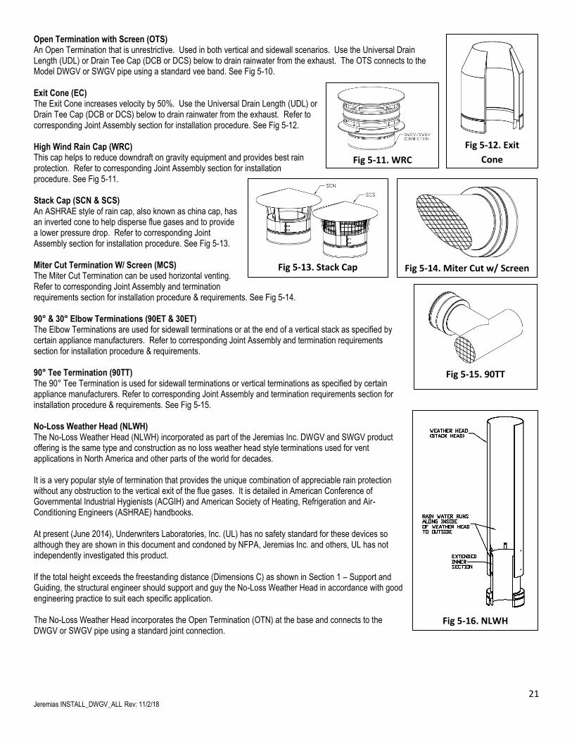
Open Termination with Screen (OTS) An Open Termination that is unrestrictive. Used in both vertical and sidewall scenarios. Use the Universal Drain Length (UDL) or Drain Tee Cap (DCB or DCS) below to drain rainwater from the exhaust. The OTS connects to the Model DWGV or SWGV pipe using a standard vee band. See Fig 5-10. Exit Cone (EC) The Exit Cone increases velocity by 50%. Use the Universal Drain Length (UDL) or Drain Tee Cap (DCB or DCS) below to drain rainwater from the exhaust. Refer to corresponding Joint Assembly section for installation procedure. See Fig 5-12. High Wind Rain Cap (WRC) This cap helps to reduce downdraft on gravity equipment and provides best rain protection. Refer to corresponding Joint Assembly section for installation procedure. See Fig 5-11. Stack Cap (SCN & SCS) An ASHRAE style of rain cap, also known as china cap, has an inverted cone to help disperse flue gases and to provide a lower pressure drop. Refer to corresponding Joint Assembly section for installation procedure. See Fig 5-13. Miter Cut Termination W/ Screen (MCS) The Miter Cut Termination can be used horizontal venting. Refer to corresponding Joint Assembly and termination requirements section for installation procedure & requirements. See Fig 5-14. 90° & 30° Elbow Terminations (90ET & 30ET) The Elbow Terminations are used for sidewall terminations or at the end of a vertical stack as specified by certain appliance manufacturers. Refer to corresponding Joint Assembly and termination requirements section for installation procedure & requirements. 90° Tee Termination (90TT) The 90° Tee Termination is used for sidewall terminations or vertical terminations as specified by certain appliance manufacturers. Refer to corresponding Joint Assembly and termination requirements section for installation procedure & requirements. See Fig 5-15. No-Loss Weather Head (NLWH) The No-Loss Weather Head (NLWH) incorporated as part of the Jeremias Inc. DWGV and SWGV product offering is the same type and construction as no loss weather head style terminations used for vent applications in North America and other parts of the world for decades. It is a very popular style of termination that provides the unique combination of appreciable rain protection without any obstruction to the vertical exit of the flue gases. It is detailed in American Conference of Governmental Industrial Hygienists (ACGIH) and American Society of Heating, Refrigeration and Air-Conditioning Engineers (ASHRAE) handbooks. At present (June 2014), Underwriters Laboratories, Inc. (UL) has no safety standard for these devices so although they are shown in this document and condoned by NFPA, Jeremias Inc. and others, UL has not independently investigated this product. If the total height exceeds the freestanding distance (Dimensions C) as shown in Section 1 – Support and Guiding, the structural engineer should support and guy the No-Loss Weather Head in accordance with good engineering practice to suit each specific application. The No-Loss Weather Head incorporates the Open Termination (OTN) at the base and connects to the DWGV or SWGV pipe using a standard joint connection.
Fig 5-11. WRC
Fig 5-12. Exit
Cone
Fig 5-14. Miter Cut w/ Screen Fig 5-13. Stack Cap
Fig 5-15. 90TT
Fig 5-16. NLWH
22 Jeremias INSTALL_DWGV_ALL Rev: 11/2/18
SECTION 6 – THIMBLES & FLASHINGS
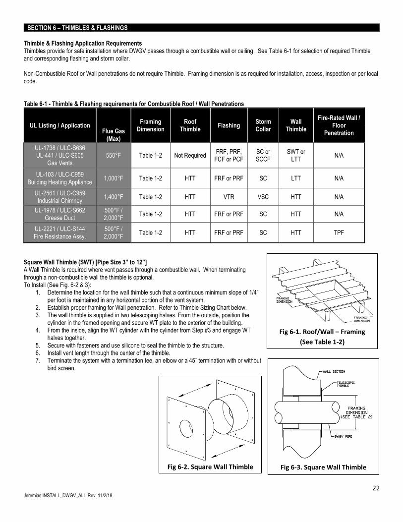
Thimble & Flashing Application Requirements Thimbles provide for safe installation where DWGV passes through a combustible wall or ceiling. See Table 6-1 for selection of required Thimble and corresponding flashing and storm collar. Non-Combustible Roof or Wall penetrations do not require Thimble. Framing dimension is as required for installation, access, inspection or per local code. Table 6-1 - Thimble & Flashing requirements for Combustible Roof / Wall Penetrations
UL Listing / Application Flue Gas
(Max)
Framing Dimension
Roof Thimble
Flashing Storm Collar
Wall Thimble
Fire-Rated Wall / Floor
Penetration
UL-1738 / ULC-S636 UL-441 / ULC-S605
Gas Vents 550°F Table 1-2 Not Required
FRF, PRF, FCF or PCF
SC or SCCF
SWT or LTT
N/A
UL-103 / ULC-C959 Building Heating Appliance
1,000°F Table 1-2 HTT FRF or PRF SC LTT N/A
UL-2561 / ULC-C959 Industrial Chimney
1,400°F Table 1-2 HTT VTR VSC HTT N/A
UL-1978 / ULC-S662 Grease Duct
500°F / 2,000°F
Table 1-2 HTT FRF or PRF SC HTT N/A
UL-2221 / ULC-S144 Fire Resistance Assy.
500°F / 2,000°F
Table 1-2 HTT FRF or PRF SC HTT TPF
Square Wall Thimble (SWT) [Pipe Size 3” to 12”] A Wall Thimble is required where vent passes through a combustible wall. When terminating through a non-combustible wall the thimble is optional. To Install (See Fig. 6-2 & 3):
1. Determine the location for the wall thimble such that a continuous minimum slope of 1/4” per foot is maintained in any horizontal portion of the vent system.
2. Establish proper framing for Wall penetration. Refer to Thimble Sizing Chart below. 3. The wall thimble is supplied in two telescoping halves. From the outside, position the
cylinder in the framed opening and secure WT plate to the exterior of the building. 4. From the inside, align the WT cylinder with the cylinder from Step #3 and engage WT
halves together. 5. Secure with fasteners and use silicone to seal the thimble to the structure. 6. Install vent length through the center of the thimble. 7. Terminate the system with a termination tee, an elbow or a 45˚ termination with or without
bird screen.
Fig 6-1. Roof/Wall – Framing
(See Table 1-2)
Fig 6-3. Square Wall Thimble
Fig 6-2. Square Wall Thimble
23 Jeremias INSTALL_DWGV_ALL Rev: 11/2/18
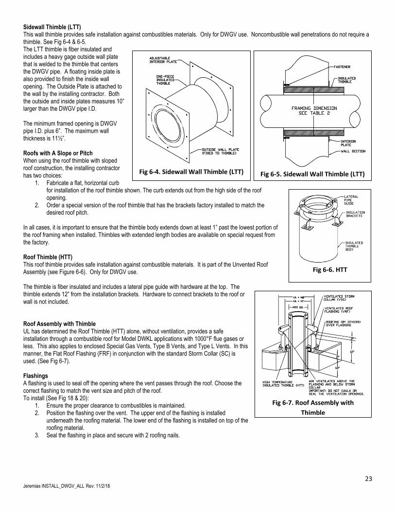
Sidewall Thimble (LTT) This wall thimble provides safe installation against combustibles materials. Only for DWGV use. Noncombustible wall penetrations do not require a thimble. See Fig 6-4 & 6-5. The LTT thimble is fiber insulated and includes a heavy gage outside wall plate that is welded to the thimble that centers the DWGV pipe. A floating inside plate is also provided to finish the inside wall opening. The Outside Plate is attached to the wall by the installing contractor. Both the outside and inside plates measures 10” larger than the DWGV pipe I.D. The minimum framed opening is DWGV pipe I.D. plus 6”. The maximum wall thickness is 11½”. Roofs with A Slope or Pitch When using the roof thimble with sloped roof construction, the installing contractor has two choices:
1. Fabricate a flat, horizontal curb for installation of the roof thimble shown. The curb extends out from the high side of the roof opening.
2. Order a special version of the roof thimble that has the brackets factory installed to match the desired roof pitch.
In all cases, it is important to ensure that the thimble body extends down at least 1” past the lowest portion of the roof framing when installed. Thimbles with extended length bodies are available on special request from the factory. Roof Thimble (HTT) This roof thimble provides safe installation against combustible materials. It is part of the Unvented Roof Assembly (see Figure 6-6). Only for DWGV use. The thimble is fiber insulated and includes a lateral pipe guide with hardware at the top. The thimble extends 12” from the installation brackets. Hardware to connect brackets to the roof or wall is not included. Roof Assembly with Thimble UL has determined the Roof Thimble (HTT) alone, without ventilation, provides a safe installation through a combustible roof for Model DWKL applications with 1000°F flue gases or less. This also applies to enclosed Special Gas Vents, Type B Vents, and Type L Vents. In this manner, the Flat Roof Flashing (FRF) in conjunction with the standard Storm Collar (SC) is used. (See Fig 6-7). Flashings A flashing is used to seal off the opening where the vent passes through the roof. Choose the correct flashing to match the vent size and pitch of the roof. To install (See Fig 18 & 20):
1. Ensure the proper clearance to combustibles is maintained. 2. Position the flashing over the vent. The upper end of the flashing is installed
underneath the roofing material. The lower end of the flashing is installed on top of the roofing material.
3. Seal the flashing in place and secure with 2 roofing nails.
Fig 6-6. HTT
Fig 6-7. Roof Assembly with
Thimble
Fig 6-5. Sidewall Wall Thimble (LTT)
Fig 6-4. Sidewall Wall Thimble (LTT)
24 Jeremias INSTALL_DWGV_ALL Rev: 11/2/18
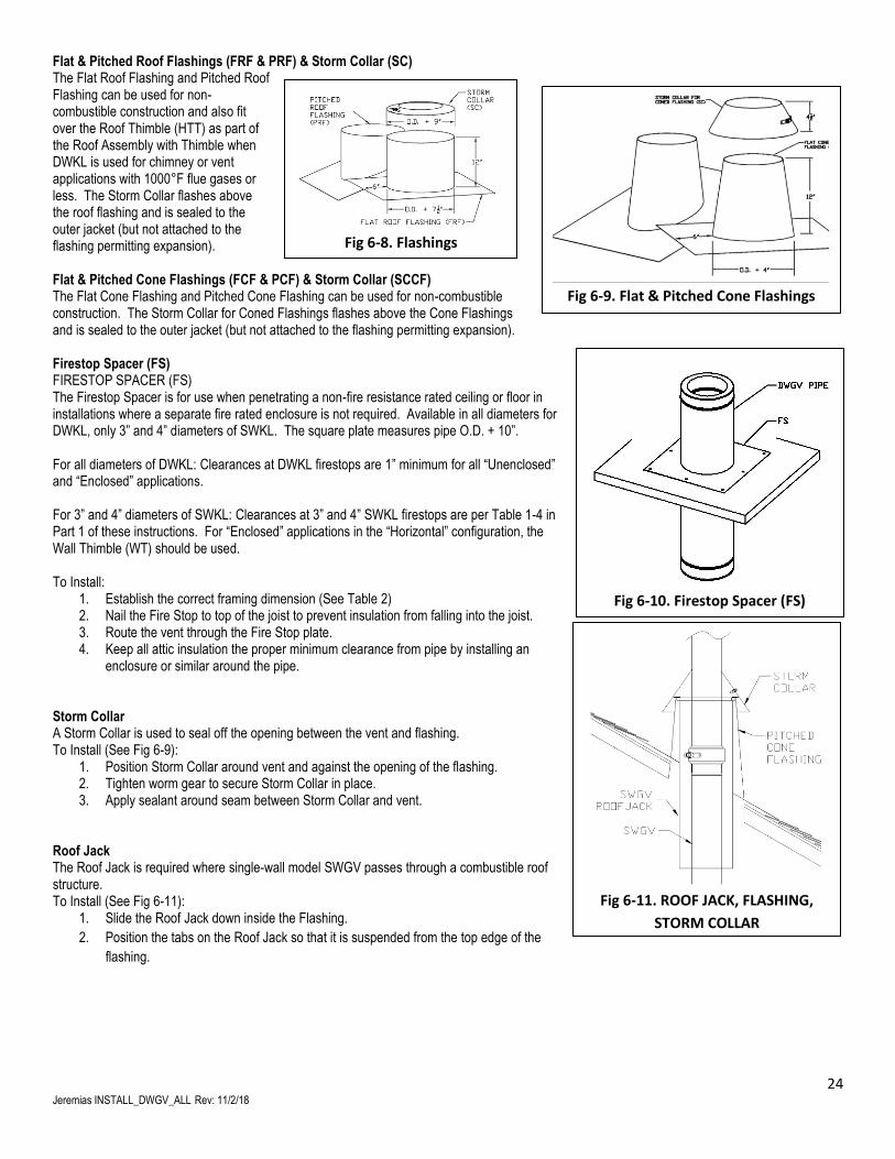
Flat & Pitched Roof Flashings (FRF & PRF) & Storm Collar (SC) The Flat Roof Flashing and Pitched Roof Flashing can be used for non-combustible construction and also fit over the Roof Thimble (HTT) as part of the Roof Assembly with Thimble when DWKL is used for chimney or vent applications with 1000°F flue gases or less. The Storm Collar flashes above the roof flashing and is sealed to the outer jacket (but not attached to the flashing permitting expansion). Flat & Pitched Cone Flashings (FCF & PCF) & Storm Collar (SCCF) The Flat Cone Flashing and Pitched Cone Flashing can be used for non-combustible construction. The Storm Collar for Coned Flashings flashes above the Cone Flashings and is sealed to the outer jacket (but not attached to the flashing permitting expansion). Firestop Spacer (FS) FIRESTOP SPACER (FS) The Firestop Spacer is for use when penetrating a non-fire resistance rated ceiling or floor in installations where a separate fire rated enclosure is not required. Available in all diameters for DWKL, only 3” and 4” diameters of SWKL. The square plate measures pipe O.D. + 10”. For all diameters of DWKL: Clearances at DWKL firestops are 1” minimum for all “Unenclosed” and “Enclosed” applications. For 3” and 4” diameters of SWKL: Clearances at 3” and 4” SWKL firestops are per Table 1-4 in Part 1 of these instructions. For “Enclosed” applications in the “Horizontal” configuration, the Wall Thimble (WT) should be used. To Install:
1. Establish the correct framing dimension (See Table 2) 2. Nail the Fire Stop to top of the joist to prevent insulation from falling into the joist. 3. Route the vent through the Fire Stop plate. 4. Keep all attic insulation the proper minimum clearance from pipe by installing an
enclosure or similar around the pipe. Storm Collar A Storm Collar is used to seal off the opening between the vent and flashing. To Install (See Fig 6-9):
1. Position Storm Collar around vent and against the opening of the flashing. 2. Tighten worm gear to secure Storm Collar in place. 3. Apply sealant around seam between Storm Collar and vent.
Roof Jack The Roof Jack is required where single-wall model SWGV passes through a combustible roof structure. To Install (See Fig 6-11):
1. Slide the Roof Jack down inside the Flashing.
2. Position the tabs on the Roof Jack so that it is suspended from the top edge of the
flashing.
Fig 6-8. Flashings
Fig 6-9. Flat & Pitched Cone Flashings
Fig 6-10. Firestop Spacer (FS)
Fig 6-11. ROOF JACK, FLASHING,
STORM COLLAR
25 Jeremias INSTALL_DWGV_ALL Rev: 11/2/18
PART 7 – Finishing Steps, Inspection & Maintenance
Final Check Before completing assembly, recheck all joints to ensure the locking band has been properly installed and has captured the bead. For Category III and IV check joint for gas tightness. Confirm all clearances and support spacing is correct. Important Notice The UL listing for this product is void if components other than the Listed Components are used. All warranties, stated or implied, are void if the vent or appliance is installed in a non-conforming manner. After installation, check all joints and supports to assure they are secure and functioning as intended and are properly sealed for containment of flue gases. Maintenance Jeremias recommends that the entire system be checked by a qualified inspector at least once a year after the system is placed in service. The installation must conform to the requirements of the appliance manufacturer’s instructions, the National Fuel Gas Code and local codes and regulations.
26 Jeremias INSTALL_DWGV_ALL Rev: 11/2/18
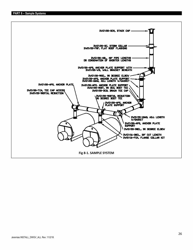
PART 8 – Sample Systems
Fig 8-1. SAMPLE SYSTEM
27 Jeremias INSTALL_DWGV_ALL Rev: 11/2/18
I. 1-Year Limited Warranty Jeremias Inc. (“Jeremias”) provides a 1-year limited warranty (“1-Year Limited Warranty”) for its UL-1738/ULC-636 Gas vents, all variations of Models SWGV and DWGV (collectively, the “Products”) for any defect in workmanship or materials under normal use from the date of shipment to the purchaser of Products (“Purchaser”), subject to the following conditions:
• Product sizing and specifications have been performed in accordance with generally accepted engineering practices.
• Correct installation and maintenance in full compliance with Jeremias’ installation and maintenance instructions as published at the time of installation.
II. Extended 25-Year Limited Warranty Jeremias provides for an extended 25-year limited warranty (“25-Year Limited Warranty”) for any defect in workmanship or materials under normal use from the date of shipment to the Purchaser, subject to the satisfaction of the following conditions:
• Products must have been designed and sized by Jeremias’ personnel.
• Availability of a written inspection report from the time of installation, or timely thereafter, by a Jeremias inspector or an inspector authorized by Jeremias, that the Product assembly and installation conformed to all of Jeremias’ assembly and installation instructions.
• Products were at all times operated and maintained in full compliance with Jeremias’ operation and maintenance instructions as published at the time of installation or as later provided to Purchaser by Jeremias.
III. Exclusion of Limited Warranty The 1-Year Limited Warranty and the 25-Year Limited Warranty (collectively the “Limited Warranty”) shall not cover (i) damages to: wear parts, e.g. seals; demonstration units; paintwork; moving parts, including but not limited to compensators, flue gas dampers, draught regulators, chimney, doors; flexible piping; insulation; consumables, such as granulates; minor Product deviations which do not effect functionality; or (ii) damages caused by: contamination of ambient air or combustion air by chlorinated hydrocarbons or other vapors which may cause excessively severe acid condensate to form within the Products; merchandise provided by other manufacturers; installation, transport or commissioning; Purchaser, an installer or other third parties; normal wear and tear; any party other than Jeremias in a willful manner; force majeure, including, but not limited to flood, fire or frost; non-compliance with the assembly, installation, operation and maintenance instructions available at www.JeremiasInc.com; assembly, installation, maintenance or repair by unqualified personnel; improper commissioning; use of Products not in accordance with their intended purpose; exposure of Products to any metals of an inferior quality; contamination of the Products between unpacking and assembly; burning of wood other than unpainted, natural wood, which has been stored for at least 3 years and which moisture level does not exceed 20%; or burning of chipboard or domestic waste. IV. Remedies If a valid Limited Warranty claim arises, Jeremias shall, it its sole discretion, either repair the Product or deliver a properly functioning Product. This Limited Warranty is limited to repair or replacement of the Product plus shipping cost to the location of the defective Product. The Limited Warranty does not cover labor costs for removal or replacement of the defective Product, unless such labor shall be carried out by Jeremias itself in its sole discretion. V. Filing of a Limited Warranty Claim Limited Warranty claims may only be asserted during the term of the applicable Limited Warranty period. Any extension of the term of the Limited Warranties shall be excluded, regardless of the legal basis. If Purchaser believes that there is a justified Limited Warranty claim, Purchaser shall notify Jeremias to that effect in writing. Any claims stemming from or relating to a Limited Warranty shall be asserted in detail within eight weeks after the discovery of the defect (the time when the notification is received by Jeremias will be the basis for determining whether a claim has been reported within this deadline) or else shall be excluded and not be recognized by Purchaser. Such notification shall include a description of the defect, original proof of purchase, and a copy of the written inspection report as described in Section II above (if applicable). VI. No Other Warranty EXCEPT AS SET FORTH EXPRESSLY THEREIN, JEREMIAS MAKES NO WARRANTIES, EITHER EXPRESS OR IMPLIED, REGARDING THE PRODUCTS, INCLUDING, BUT NOT LIMITED TO, THE IMPLIED WARRANTIES OF MERCHANTABILITY AND FITNESS FOR A PARTICULAR PURPOSE. VII. Damages Disclaimer and Limitation IN NO EVENT SHALL JEREMIAS BE LIABLE TO ANY CLIENT OR ANY OTHER PERSON FOR ANY (A) INDIRECT, INCIDENTAL, CONSEQUENTIAL OR PUNITIVE DAMAGES, INCLUDING LOSS OF PROFIT OR GOODWILL OR (B) DIRECT DAMAGES TO BODY, HEALTH OR PROPERTY FOR ANY MATTER ARISING OUT OF OR RELATING TO THE PRODUCTS, WHETHER SUCH LIABILITY IS ASSERTED ON THE BASIS OF CONTRACT, TORT OR OTHERWISE EVEN IF JEREMIAS HAS BEEN ADVISED OF THE POSSIBILITY OF SUCH DAMAGES. IN NO EVENT SHALL JEREMIAS’ TOTAL AGGREGATE LIABILITY FOR DAMAGES EXCEED THE GREATER OF THE AMOUNT OF (A) TOTAL COMPENSATION PAID BY PURCHASER TO JEREMIAS FOR THE PRODUCTS, OR (B) PROCEEDS AVAILABLE FROM ANY INSURANCE POLICY IN EFFECT AND APPLICABLE TO THE EVENT GIVING RISE TO SUCH LIABILITY. VIII. Notice Any notice or other communication hereunder to Jeremias shall be sent postage prepaid, by certified mail, by courier such as United Parcel Service or e-mail, to the following: Jeremias Inc., 983 Industrial Park Drive, Marietta, GA 30062, E-mail: [email protected]. Notices shall be effective upon receipt. IX. Terms and Conditions of Sale Purchaser’s Terms and Conditions of Sale as currently in effect shall govern these Limited Warranties, including without limitation the rights and responsibilities granted hereunder.
28 Jeremias INSTALL_DWGV_ALL Rev: 11/2/18
NOTES
Jeremias Inc.
983 Industrial Park Drive, Marietta, GA 30062
678-388-2740 Fax: 678-388-2744
[email protected] www.jeremiasinc.com