double regulating valve · double regulating valve. iint nrithni 2. iint nrithni 3 table of...
TRANSCRIPT

Effiziente Energietechnik
www.ballorex.com
Double Regulating Valve

Effiziente Energietechnik
2
Effiziente Energietechnik
3
Table of contents
Chapter Ballorex Vario DN 10-50
1. Safety instructions 41.1 Rules/regulations 41.2 Intended use 51.3 Initial operation 51.4 Working on the system 51.5 Liability 5
2. Introduction 62.1 Description 62.2 Benefits 62.3 Design 72.4 Flow balancing 72.5 Operation 82.6 Mounting 10
3. Applications 11
4. Product data sheet 154.1 Product finder 154.2 Ballorex Vario DN 10-50 164.2.1 DN 10-50 female/female 164.2.2 With drain – DN 10-50 female/female 184.3 Flow diagrams 204.4 Valve settings 274.5 Measuring signal diagrams 344.6 Measuring accuracy 41
5. Accessoires 45
6. Sizing example 466.1 Ballorex Vario system sizing 466.2 General specifications DN 10-50 49

Effiziente Energietechnik
4
Please read the instructions carefully before installationThe installation and initial operation of the assembly may be carried out only by an authorised specialist company.Prior to starting work, familiarise yourself with all parts and how they are handled.The application examples in these operating instructions are ideas sketched out. Local laws and regulations have to be observed.
Target group:These instructions are intended for authorised specialists exclusively. Work on the heating system, the potable water as well as gas and power network may be carried out by specialists only.
Please follow these safety instructions carefully in order to avoid hazards and damage to people and property.
1.1 Rules/regulations
Please observe the applicable accident prevention regulations, the environmental legislation and the legal rules for mounting, installation and operation. Moreover, please observe the appropriate guidelines of German standard DIN, EN, DVGW, VDI and VDE (including lightning protection) as well as all current relevant country-specific standards, laws and regulations. Old and newly enforced regulations and standards shall apply, if they are relevant for the indivi-dual case. Moreover, the regulations of your local energy supply company have to be observed.
Electrical connection:Electrical wiring work may be carried out by qualified electricians only. The VDE regulations and the specifi-cations of the relevant energy supply company have to be met.
Excerpt:Installation and construction of heat generators as well as the drinking water heaters:DIN EN 4753, Part 1: Water heater and water heating plants for potable and process water.DIN 18 380: Heating systems and central water heating systemsDIN 18 381: Gas, water, waste water installation work within buildings.DIN 18 421: Insulation work on technical plantsAV B Wa s V Regulations concerning the general conditions for the supply with waterDIN EN 806 ff.: Technical rules for potable water installationDIN 1988 ff.: Technical rules for potable water installation (national addition)DIN EN 1717: Protection of potable water against contaminationsDIN 4751: Safety equipment
Electrical connection:VDE 0100: Erection of electrical equipment, grounding, protective conductor, potential equalisation conductor.VDE 0701: Repair, modification and testing of electrical devices.VDE 0185: General aspects on the erection of lightning protection systems.VDE 0190: Main potential equalisation of electrical plants.VDE 0855: Installation of antenna plants (shall apply mutatis mutandis).
1. Safety instructions

Effiziente Energietechnik
5
Additional remarks:VDI 6002 Sheet 1: General principles, system technology and use in house buildingVDI 6002, Sheet 2: Use in students’ hostels, retirement homes, hospitals, indoor swimming pools and on camping facilities
Caution:Prior to any electrical wiring work on pumps and controls, these modules have to be disconnected from voltage correctly.
1.2 Intended use
Inexpert installation as well as use for a purpose not intended of the assembly shall rule out all warranty claims.All shut-off valves may be closed by an approved specialist only in case of servicing as otherwise the safety valves are not effective.
Do not modify the electrical components, the construction or the hydraulic components! You will impair the safe function of the plant otherwise.
1.3 Initial operation
Prior to the initial operation, the plant has to be tested for tightness, correct hydraulic connection as well as accurate and correct electrical connection. In addition, the plant has to be flushed correctly and/as required in keeping with German standard DIN 4753. The initial operation has to be carried out by a trained specialist, which has to be recor-ded in writing. In addition, the settings have to be put down in writing. The technical documentation has to be available at the device.
1.4 Working on the system
The plant has to be de-energised and to be checked for the absence of voltage (such as on the separate fuse or a master switch). Secure the plant against unintentional restart.(If gas is used as fuel, close the gas shut-off valve and secure against unintentional opening.) Repair work on compo-nent parts with a safety-relevant function is impermissible.
1.5 Liability
We reserve all copyrights for this document. Wrongful use, in particular reproduction and forwarding to third parties shall not be permitted.These installation and operating instructions shall have to be handed to the customer. The executing and/or autho-rised tradesperson (such as fitter) shall have to explain the function and operation of the plant to the customer in an intelligible manner.

Effiziente Energietechnik
6
Ballorex Vario
Variable Orifice Double Regulating Valve (VODRV)
DN 10- 503/8” - 2”
2.1 Description
Ballorex Vario is a variable orifice double regulating valve for balancing water-based heating and cooling systems. Thebalancing performed ensures the required distribution of flow in individual risers and terminal units. Applications aretypically central heating or cooling systems, as well as fan coil units in multi-storey and high-rise buildings.
Ballorex Vario is available in valves DN 10 to DN 50, manufactured in dezincification resistant brass (DZR). For valvesizes DN 65 - 600 the Ballorex Venturi valve range is recommended.
Ballorex Vario can optionally be provided with a drain valve. Apart from system draining, the drain valve can also beused to connect a capillary tube from the Ballorex Delta differential pressure control valve. The Ballorex Delta andBallorex Vario valves are in combination used for differential pressure control and maximum flow limiting.
2.2 Benefits
• Product range from DN 10 to DN 50 for heating and cooling systems• Measuring, pre-setting, draining and isolation functions all in one unit• Compact design for installations in confined spaces• Flow direction is irrelevant for the valve installation• Pre-setting is fast and simple using an Allen key• Setting scale is precise and easy to read• Isolation of flow is simply done using the quarter-turn handle• No change in pre-setting when isolated and re-opened• Drain valve can be rotated 360° for easy service• Perfect as a partner valve for the Ballorex Delta, differential pressure control valves
2. Introduction
Effiziente Energietechnik
7
2.3 Design
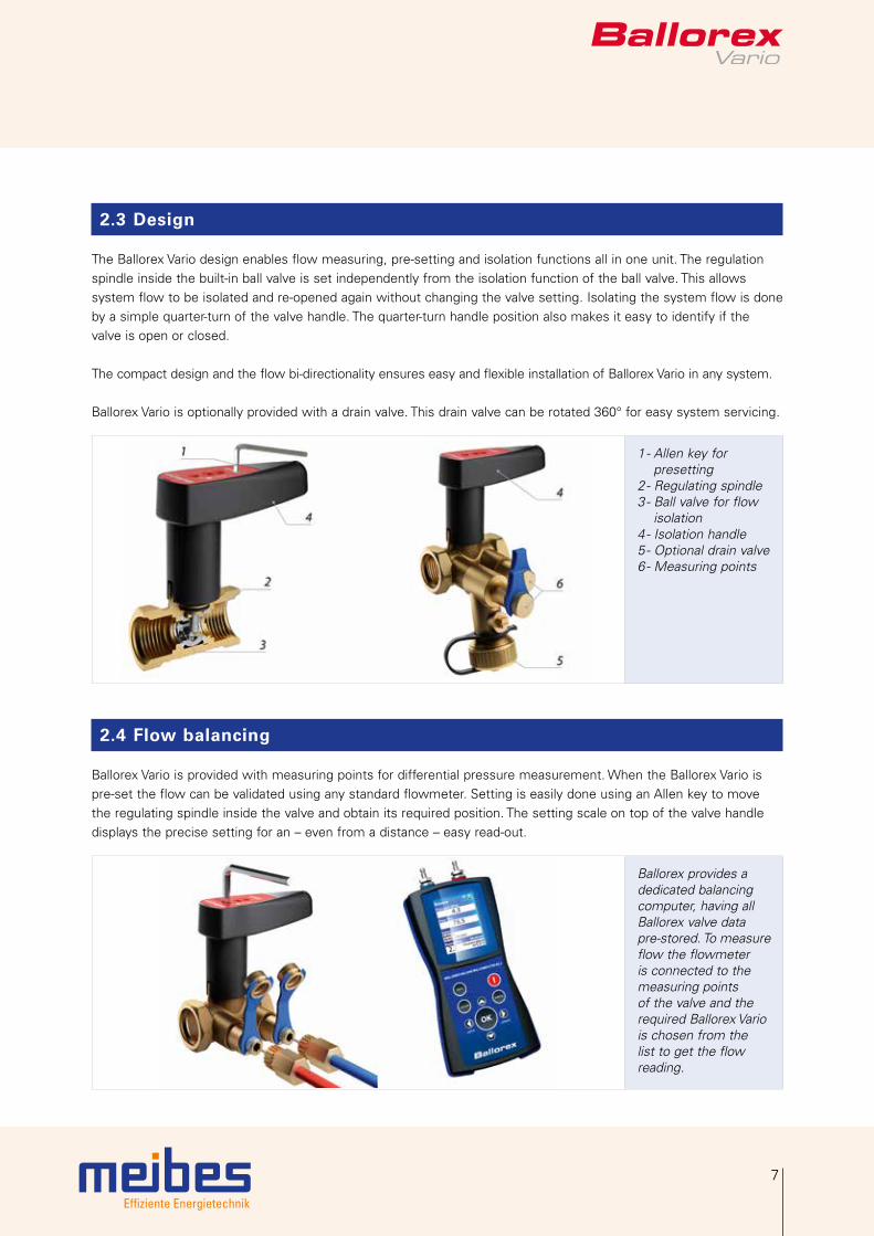
The Ballorex Vario design enables flow measuring, pre-setting and isolation functions all in one unit. The regulationspindle inside the built-in ball valve is set independently from the isolation function of the ball valve. This allowssystem flow to be isolated and re-opened again without changing the valve setting. Isolating the system flow is doneby a simple quarter-turn of the valve handle. The quarter-turn handle position also makes it easy to identify if thevalve is open or closed.
The compact design and the flow bi-directionality ensures easy and flexible installation of Ballorex Vario in any system.
Ballorex Vario is optionally provided with a drain valve. This drain valve can be rotated 360° for easy system servicing.
1 - Allen key for presetting2 - Regulating spindle3 - Ball valve for flow isolation4 - Isolation handle5 - Optional drain valve6 - Measuring points
2.4 Flow balancing
Ballorex Vario is provided with measuring points for differential pressure measurement. When the Ballorex Vario is pre-set the flow can be validated using any standard flowmeter. Setting is easily done using an Allen key to move the regulating spindle inside the valve and obtain its required position. The setting scale on top of the valve handle displays the precise setting for an – even from a distance – easy read-out.
Ballorex provides a dedicated balancing computer, having all Ballorex valve data pre-stored. To measure flow the flowmeter is connected to the measuring points of the valve and the required Ballorex Vario is chosen from the list to get the flow reading.
Effiziente Energietechnik
8
2. Introduction
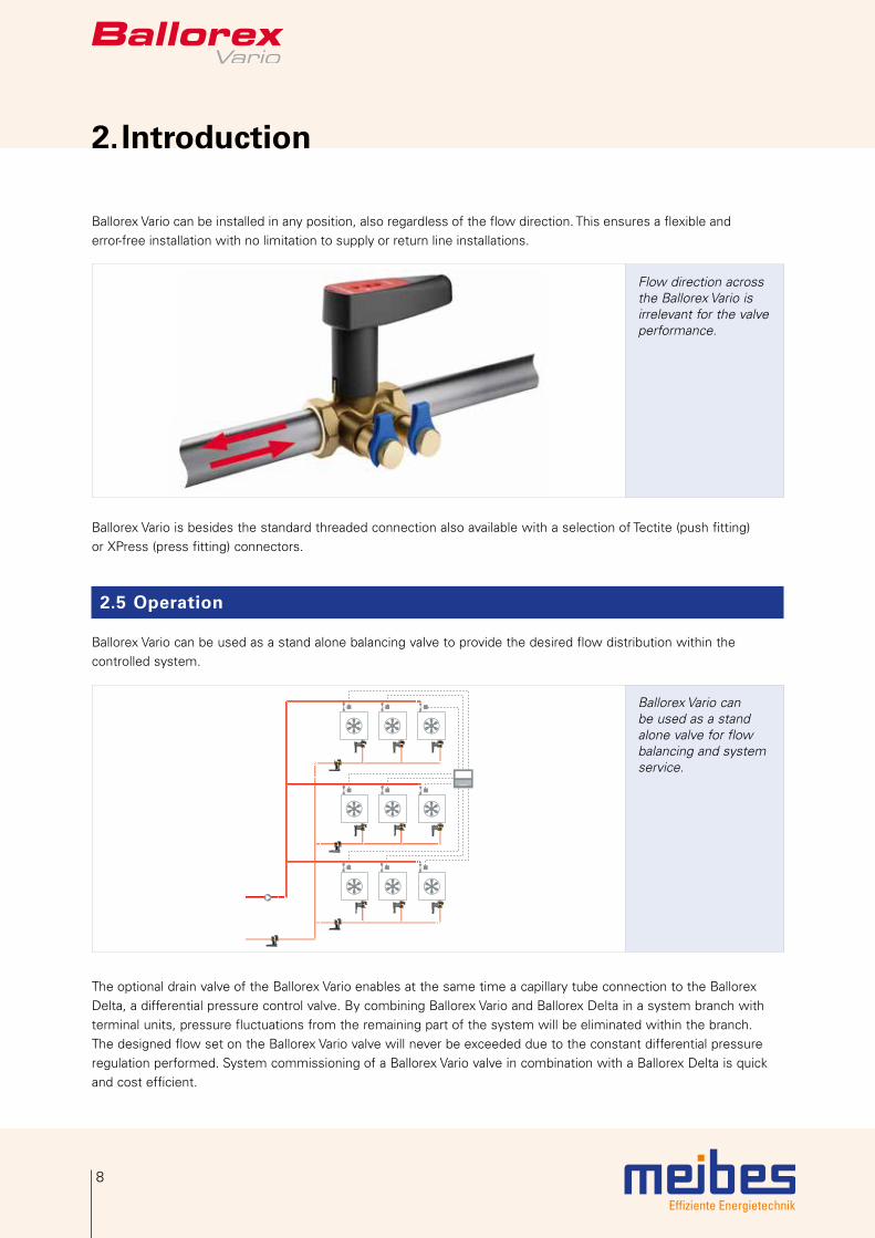
Ballorex Vario can be installed in any position, also regardless of the flow direction. This ensures a flexible and error-free installation with no limitation to supply or return line installations.
Flow direction acrossthe Ballorex Vario isirrelevant for the valveperformance.
Ballorex Vario is besides the standard threaded connection also available with a selection of Tectite (push fitting)or XPress (press fitting) connectors.
2.5 Operation
Ballorex Vario can be used as a stand alone balancing valve to provide the desired flow distribution within thecontrolled system.
Ballorex Vario can be used as a stand alone valve for flow balancing and system service.
The optional drain valve of the Ballorex Vario enables at the same time a capillary tube connection to the Ballorex Delta, a differential pressure control valve. By combining Ballorex Vario and Ballorex Delta in a system branch with terminal units, pressure fluctuations from the remaining part of the system will be eliminated within the branch. The designed flow set on the Ballorex Vario valve will never be exceeded due to the constant differential pressure regulation performed. System commissioning of a Ballorex Vario valve in combination with a Ballorex Delta is quick and cost efficient.
Effiziente Energietechnik
9
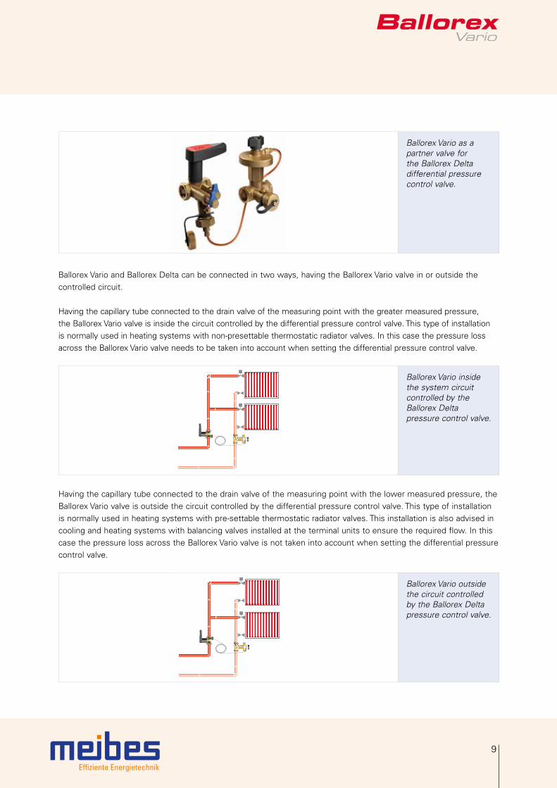
Ballorex Vario as a partner valve for the Ballorex Delta differential pressure control valve.
Ballorex Vario and Ballorex Delta can be connected in two ways, having the Ballorex Vario valve in or outside the controlled circuit.
Having the capillary tube connected to the drain valve of the measuring point with the greater measured pressure, the Ballorex Vario valve is inside the circuit controlled by the differential pressure control valve. This type of installation is normally used in heating systems with non-presettable thermostatic radiator valves. In this case the pressure loss across the Ballorex Vario valve needs to be taken into account when setting the differential pressure control valve.
Ballorex Vario inside the system circuit controlled by the Ballorex Delta pressure control valve.
Having the capillary tube connected to the drain valve of the measuring point with the lower measured pressure, the Ballorex Vario valve is outside the circuit controlled by the differential pressure control valve. This type of installation is normally used in heating systems with pre-settable thermostatic radiator valves. This installation is also advised in cooling and heating systems with balancing valves installed at the terminal units to ensure the required flow. In this case the pressure loss across the Ballorex Vario valve is not taken into account when setting the differential pressure control valve.
Ballorex Vario outside the circuit controlled by the Ballorex Delta pressure control valve.

Effiziente Energietechnik
10
2. Introduction
2.6 Mounting
Ballorex Vario can be installed regardless of flow direction and 360° around the pipe axis. It requires a straight pipe of 5 × pipe diameter when installed directly after a bend, and 2 × pipe diameter of straight piping when installed directly before a bend. A straight pipe of 10 × pipe diameter is required when Ballorex Vario is installed directly after the pump. Ballorex Vario is set using an Allen key to adjust the valve until the required flow is obtained.

Effiziente Energietechnik
11
3. Applications
Application 1 - Underfloor heating system
In an underfloor heating system Ballorex Vario ensures the required flow distribution to all manifolds. Actuators connected to the room thermostat, or the BMS system, control the flow in each loop by opening or closing two-way valves in reference to the air temperature.
The flow and temperature control ensures the required indoor thermal comfort.
Application 2 - Fan coil system with two-way motorized valves (variable flow system)
In a variable flow system with two-way motorized valves installed, the Ballorex Vario provides hydronic balance and ensures that all fan coil units have the desired flow at maximum load conditions.
Actuators installed on two-way motorized valves, connected to the room thermostat or BMS system, control the flow in each fan coil unit by opening or closing twoway valves in reference to the air temperature.
The flow and temperature controlensures the required indoor thermalcomfort.

Effiziente Energietechnik
12
3. Applications
Application 3 - Fan coil system with three-way motorized valves (constant flow system)
In a constant flow system with three-way motorized valves, the Ballorex Vario provides hydronic balance and ensures that all units have the required flow at maximum load conditions. This is possible as the Ballorex Vario valves ensure the same pressure loss in the terminal unit branch regardless of the threeway valve position.
Actuators installed on three-way motorized valves, connected to a room thermostat or BMS system, control the flow in each unit by opening or closing the threeway valves in reference to the air temperature.
The flow and temperature controlensure the required indoor thermalcomfort.
Application 4 - Central heating system with differential pressure control valves
In a central heating system branch having Ballorex Vario and Ballorex Delta differential pressure control valves installed, pressure fluctuations from the remaining part of the system will be eliminated within the branch. This provides stable pressure and flow conditions, and prevents also possible noise nuisance caused by high differential pressure across radiator thermostats, two-way control valves, or other components in the system.
Balancing a system comprisingBallorex Vario and Ballorex Delta isquick and cost efficient.
Effiziente Energietechnik
13
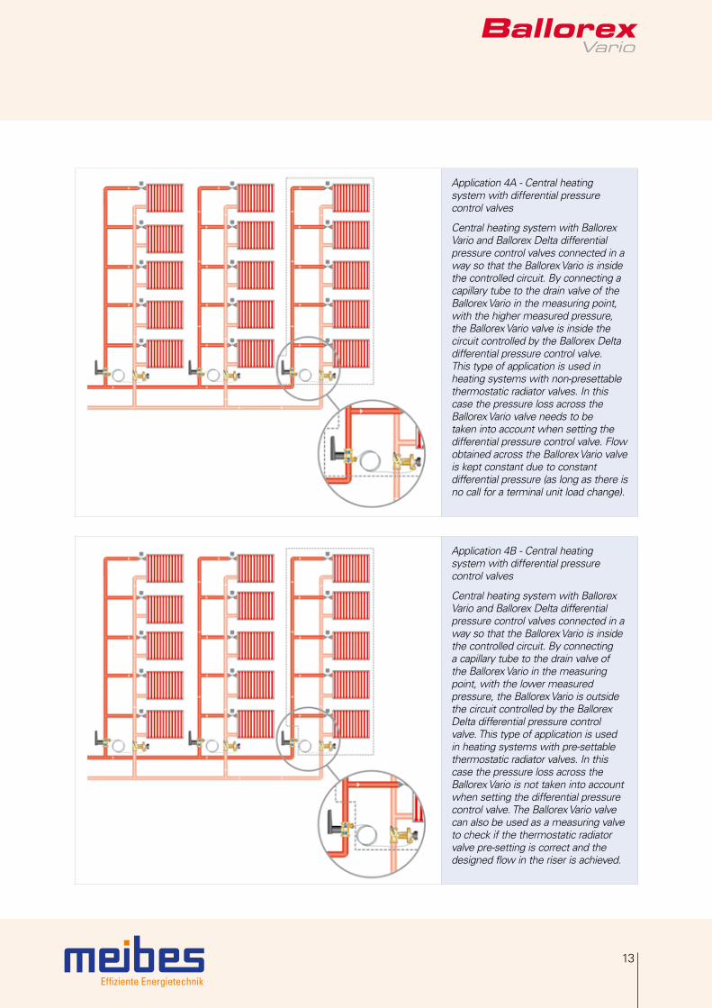
Application 4A - Central heatingsystem with differential pressurecontrol valves
Central heating system with Ballorex Vario and Ballorex Delta differential pressure control valves connected in a way so that the Ballorex Vario is inside the controlled circuit. By connecting a capillary tube to the drain valve of the Ballorex Vario in the measuring point, with the higher measured pressure, the Ballorex Vario valve is inside the circuit controlled by the Ballorex Delta differential pressure control valve. This type of application is used in heating systems with non-presettable thermostatic radiator valves. In this case the pressure loss across the Ballorex Vario valve needs to be taken into account when setting the differential pressure control valve. Flow obtained across the Ballorex Vario valveis kept constant due to constant differential pressure (as long as there is no call for a terminal unit load change).
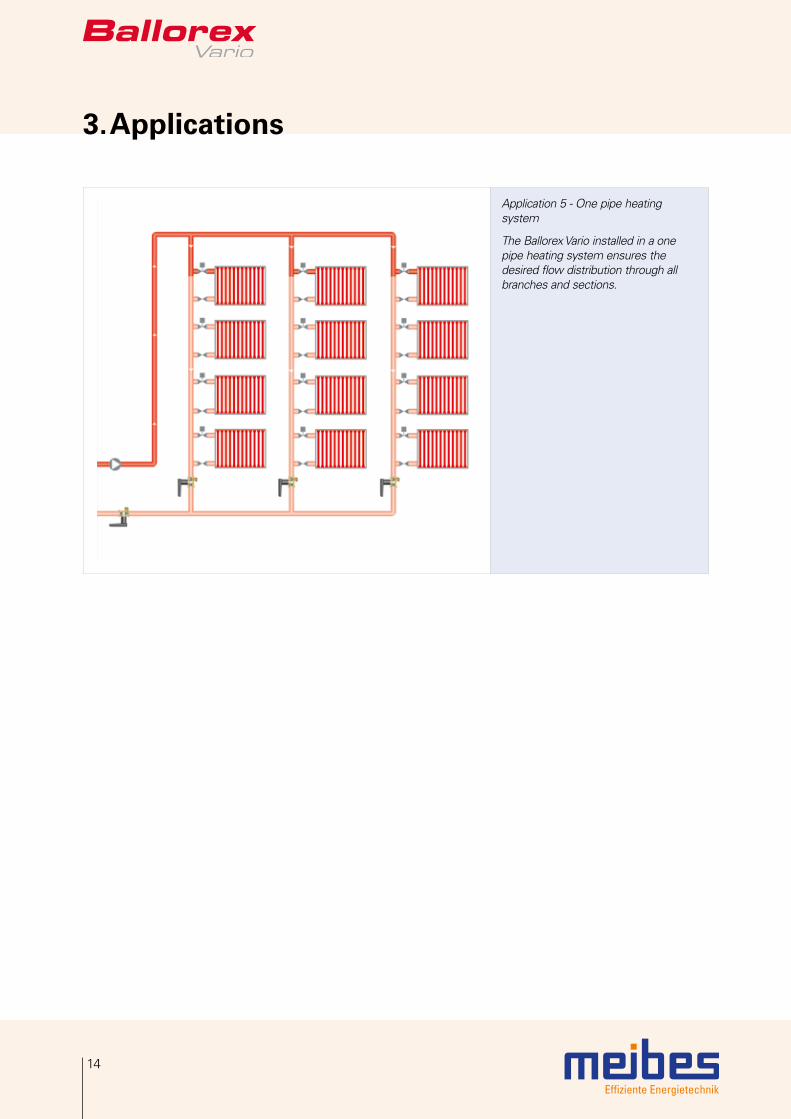
Application 4B - Central heatingsystem with differential pressurecontrol valves
Central heating system with Ballorex Vario and Ballorex Delta differential pressure control valves connected in a way so that the Ballorex Vario is inside the controlled circuit. By connecting a capillary tube to the drain valve of the Ballorex Vario in the measuring point, with the lower measured pressure, the Ballorex Vario is outside the circuit controlled by the Ballorex Delta differential pressure control valve. This type of application is used in heating systems with pre-settable thermostatic radiator valves. In this case the pressure loss across the Ballorex Vario is not taken into account when setting the differential pressure control valve. The Ballorex Vario valve can also be used as a measuring valve to check if the thermostatic radiator valve pre-setting is correct and thedesigned flow in the riser is achieved.
Effiziente Energietechnik
14
3. Applications
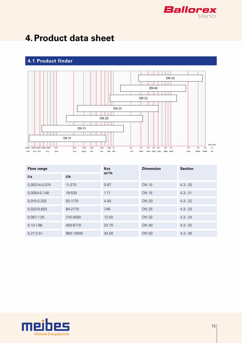
Application 5 - One pipe heating system
The Ballorex Vario installed in a one pipe heating system ensures the desired flow distribution through all branches and sections.
Effiziente Energietechnik
15
4. Product data sheet
4.1 Product finder
72.0 108.0 216 288 360144
l/s
l/h
Flow rate
0.02 0.030.010.005 0.007 0.04 0.06 0.08 0.1 0.2 0.3 0.4 0.5 0.6 0.8 1.0
36.0
4.0 3.0 2.0
720 1080 1440 1800 2160 2880 3600 7200 10800 1440018.0 25.2
0.003 0.004
10.8 14.4
0.006
DN 32
DN 40
DN 25
DN 50
DN 20
DN 15
DN 10
Flow range Kvsm3/h
Dimension Section
l/s l/h
0.00314-0.074 11-270 0.67 DN 10 4.3 - 20
0.0054-0.148 19-530 1.71 DN 15 4.3 - 21
0.015-0.325 55-1170 4.40 DN 20 4.3 - 22
0.023-0.603 84-2170 7.46 DN 25 4.3 - 23
0.087-1.25 310-4500 13.50 DN 32 4.3 - 24
0.13-1.88 450-6770 23.70 DN 40 4.3 - 25
0.27-3.51 960-12640 34.50 DN 50 4.3 - 26
Effiziente Energietechnik
16
4. Product data sheet
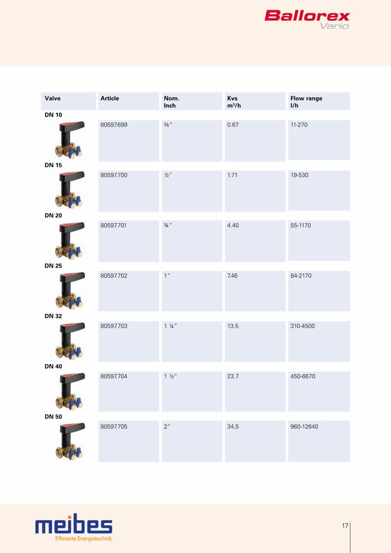
4.2 Ballorex Vario DN 10-50
4.2.1 DN 10-50 female/female
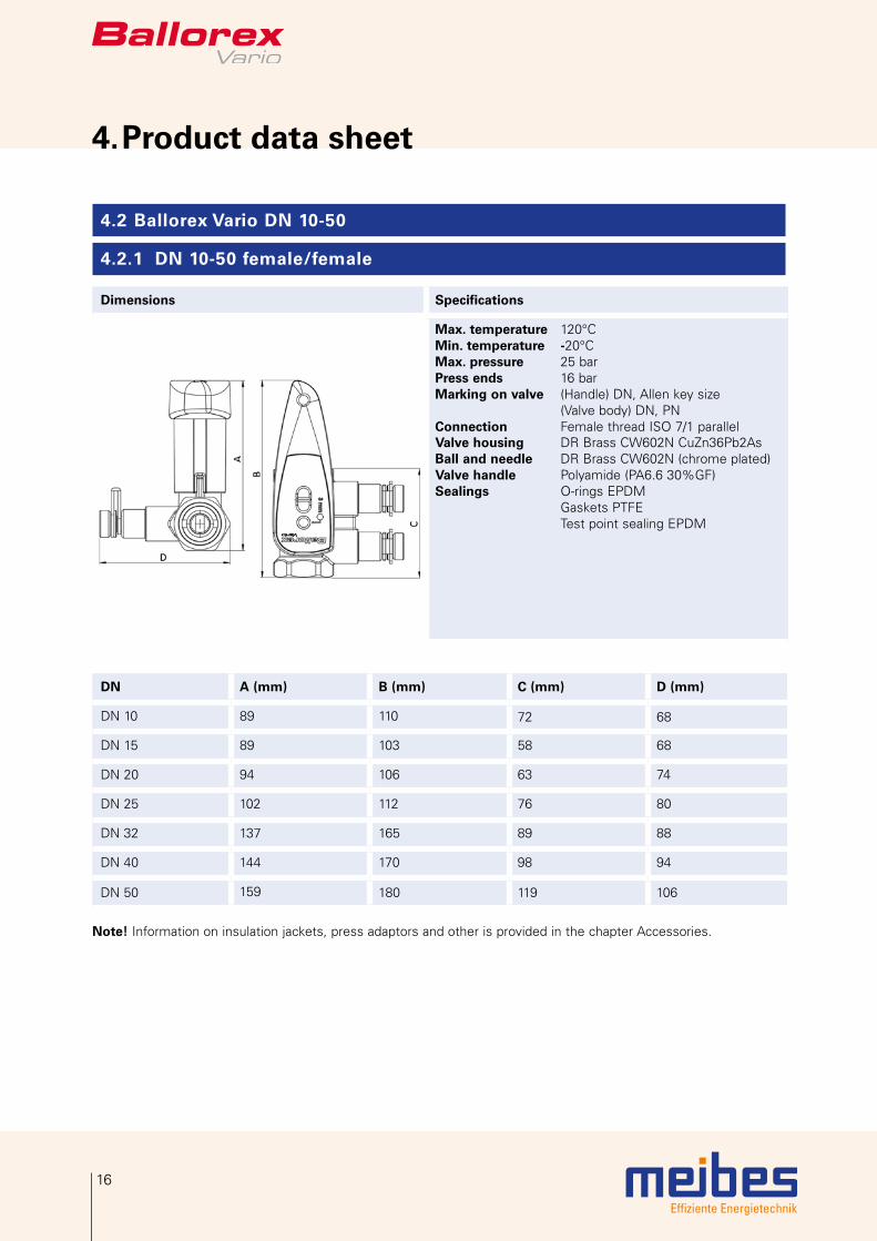
Dimensions Specifications
Max. temperature 120°CMin. temperature -20°CMax. pressure 25 barPress ends 16 barMarking on valve (Handle) DN, Allen key size (Valve body) DN, PN Connection Female thread ISO 7/1 parallel Valve housing DR Brass CW602N CuZn36Pb2AsBall and needle DR Brass CW602N (chrome plated)Valve handle Polyamide (PA6.6 30%GF)Sealings O-rings EPDM Gaskets PTFE Test point sealing EPDM
DN A (mm) B (mm) C (mm) D (mm)
DN 10 89 110 72 68
DN 15 89 103 58 68
DN 20 94 106 63 74
DN 25 102 112 76 80
DN 32 137 165 89 88
DN 40 144 170 98 94
DN 50 159 180 119 106
Note! Information on insulation jackets, press adaptors and other is provided in the chapter Accessories.
Effiziente Energietechnik
17
Valve Article Nom. Inch
Kvsm3/h
Flow rangel/h
DN 10
80597.699 “ 0.67 11-270
DN 15
80597.700 ½“ 1.71 19-530
DN 20
80597.701 ¾“ 4.40 55-1170
DN 25
80597.702 1“ 7.46 84-2170
DN 32
80597.703 1 ¼“ 13.5 310-4500
DN 40
80597.704 1 ½“ 23.7 450-6670
DN 50
80597.705 2“ 34,5 960-12640
Effiziente Energietechnik
18
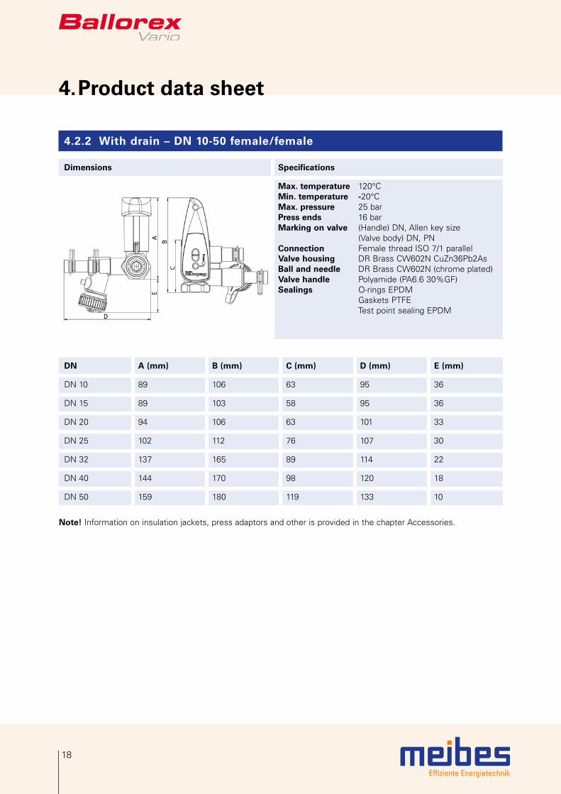
4. Product data sheet
4.2.2 With drain – DN 10-50 female/female
Dimensions Specifications
Max. temperature 120°CMin. temperature -20°CMax. pressure 25 barPress ends 16 barMarking on valve (Handle) DN, Allen key size (Valve body) DN, PN Connection Female thread ISO 7/1 parallel Valve housing DR Brass CW602N CuZn36Pb2AsBall and needle DR Brass CW602N (chrome plated)Valve handle Polyamide (PA6.6 30%GF)Sealings O-rings EPDM Gaskets PTFE Test point sealing EPDM
DN A (mm) B (mm) C (mm) D (mm) E (mm)
DN 10 89 106 63 95 36
DN 15 89 103 58 95 36
DN 20 94 106 63 101 33
DN 25 102 112 76 107 30
DN 32 137 165 89 114 22
DN 40 144 170 98 120 18
DN 50 159 180 119 133 10
Note! Information on insulation jackets, press adaptors and other is provided in the chapter Accessories.

Effiziente Energietechnik
19
Valve Article Nom. Inch
Kvsm3/h
Flow rangel/h
DN 10
80597.7112 “ 0.67 11-270
DN 15
80597.706 ½“ 1.71 19-530
DN 20
80597.707 ¾“ 4.40 55-1170
DN 25
80597.708 1“ 7.46 84-2170
DN 32
80597.709 1 ¼“ 13.5 310-4500
DN 40
80597.710 1 ½“ 23.7 450-6670
DN 50
80597.711 2“ 34,5 960-12640

Effiziente Energietechnik
20
4. Product data sheet
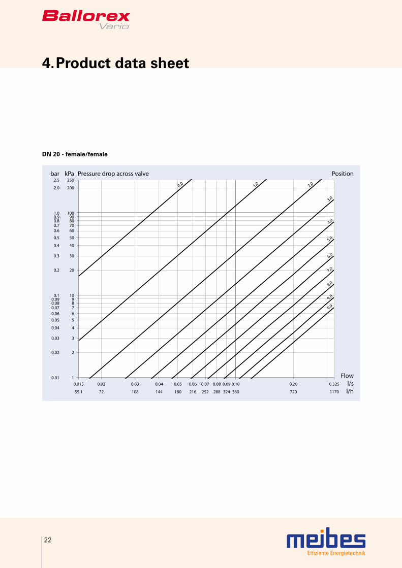
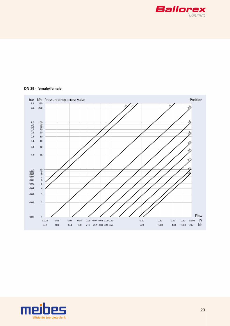
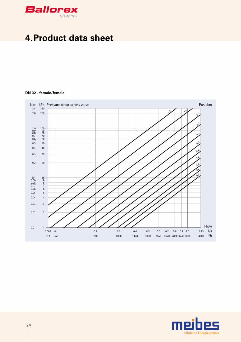
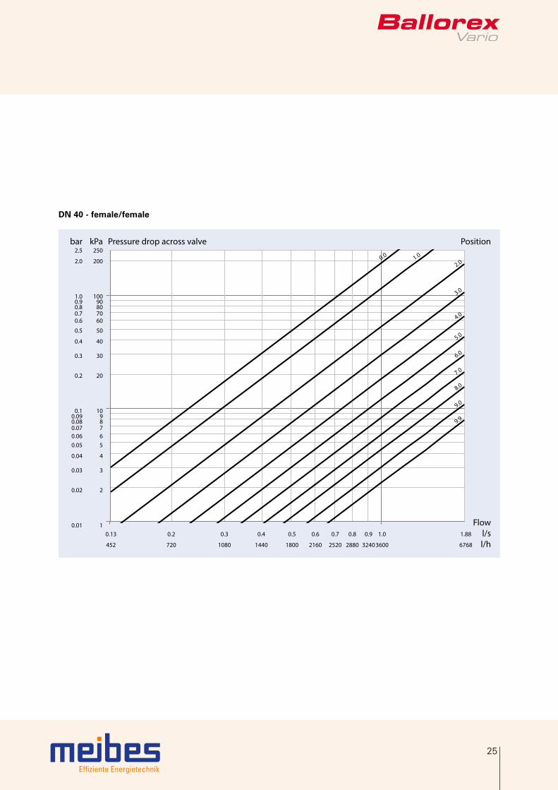
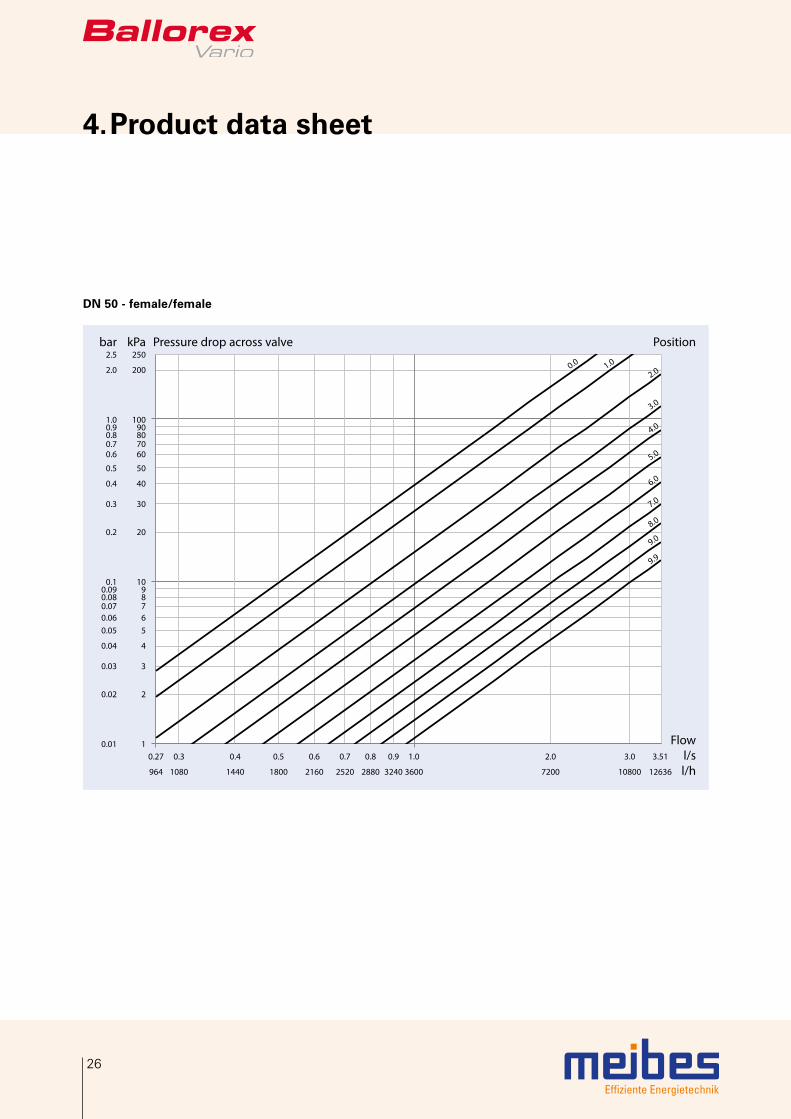
4.3 Flow diagrams
The graph is used to determine the total pressure loss across the Ballorex Vario valve at a given pre-setting and flow rate.
The minimum digital scale setting is 0.0 and the maximum setting (fully open valve) is 9.9. One hundred different positions, at an increment of 0.1, are possible, and each position corresponds to a different Kv value.
The Kv value and the Kvs value (at a fully open valve) refer to the pressure loss across the entire valve. These values are used for system sizing and pump selection. The Kv and the Kvs values differ from the Kvm value which is connected to the pressure loss at the measuring points. This difference is a result of turbulence occurring in the measuring area. The Kvm value is used during system balancing to secure correct flow readings from the flowmeter. The Kvm value corresponding to a specific Ballorex Vario valve setting is typed into the flowmeter for a flow read-out.
A pressure loss of up to 250 kPa is allowed across the Ballorex Vario valve. Within the working range it should beassured that cavitation does not occur at any given pressure loss. Valve sizing example is provided in chapter 6.
DN 10 - female/female
0.01 0.10
0.00314 0.07
360.0272
0.04144
0.03108
0.05180
0.08288252 360
2.52.0
1.00.0 0.51.5
6.0
5.0
4.0
3.0
9.08.07.0
Flow (l/s)(l/h)
Pressure drop across valve kPa250
200
1009080706050
40
30
20
10987654
3
2
1
bar2.5
2.0
1.00.90.80.70.60.5
0.4
0.3
0.2
0.10.090.080.070.060.050.04
0.03
0.02
0.01
Position

Effiziente Energietechnik
21
DN 15 - female/female
Pressure drop across valve Position
Flowl/sl/h
kPa250
200
10090807060
50
40
30
20
1098765
4
3
2
1
9.99.0
8.0
7.0
6.0
5.0
4.0
3.02.01.00.0
bar2.5
2.0
1.00.90.80.70.6
0.5
0.4
0.3
0.2
0.10.090.080.070.060.05
0.04
0.03
0.02
0.01 0.0054 0.007 0.01 0.02 0.03 0.04 0.05 0.06 0.07 0.08 0.10 0.148
19.4 25.2 36 72 108 144 180 216 252 288 360 533
Effiziente Energietechnik
22
4. Product data sheet
DN 20 - female/female
9.9
9.0
8.0
7.0
6.0
5.0
4.0
3.0
2.01.00.0
Pressure drop across valve Position
Flowl/sl/h
kPa250
200
10090807060
50
40
30
20
1098765
4
3
2
1
bar2.5
2.0
1.00.90.80.70.6
0.5
0.4
0.3
0.2
0.10.090.080.070.060.05
0.04
0.03
0.02
0.01 0.015 0.02 0.03 0.04 0.05 0.06 0.07 0.08 0.09 0.10 0.20 0.325
55.1 72 108 144 180 216 252 288 324 360 720 1170
Effiziente Energietechnik
23
DN 25 - female/female
9.99.0
8.0
7.0
6.0
5.0
4.0
3.02.01.00.0
Pressure drop across valve Position
Flowl/sl/h
kPa250
200
10090807060
50
40
30
20
1098765
4
3
2
1
bar2.5
2.0
1.00.90.80.70.6
0.5
0.4
0.3
0.2
0.10.090.080.070.060.05
0.04
0.03
0.02
0.01 0.023 0.03 0.04 0.05 0.06 0.07 0.08 0.09 0.10 0.20 0.30 0.40 0.50 0.603
83.5 108 144 180 216 252 288 324 360 720 1080 1440 1800 2171
Effiziente Energietechnik
24
4. Product data sheet
DN 32 - female/female
9.9
9.08.0
7.0
6.0
5.0
4.0
3.0
2.01.00.0
Pressure drop across valve Position
Flowl/sl/h
kPa250
200
10090807060
50
40
30
20
1098765
4
3
2
1
bar2.5
2.0
1.00.90.80.70.6
0.5
0.4
0.3
0.2
0.10.090.080.070.060.05
0.04
0.03
0.02
0.01 0.087 0.1 0.2 0.3 0.4 0.5 0.6 0.7 0.8 0.9 1.0 1.25
313 360 720 1080 1440 1800 2160 2520 2880 3240 3600 4500
Effiziente Energietechnik
25
DN 40 - female/female
9.9
9.0
8.0
7.0
6.0
5.0
4.0
3.0
2.01.00.0
Pressure drop across valve Position
Flowl/sl/h
kPa250
200
10090807060
50
40
30
20
1098765
4
3
2
1
bar2.5
2.0
1.00.90.80.70.6
0.5
0.4
0.3
0.2
0.10.090.080.070.060.05
0.04
0.03
0.02
0.01 0.13 0.2 0.3 0.4 0.5 0.6 0.7 0.8 0.9 1.0 1.88
452 720 1080 1440 1800 2160 2520 2880 3240 3600 6768
Effiziente Energietechnik
26
4. Product data sheet
DN 50 - female/female
9.9
9.0
8.0
7.0
6.0
5.0
4.0
3.0
2.01.00.0
Pressure drop across valve Position
Flowl/sl/h
kPa250
200
10090807060
50
40
30
20
1098765
4
3
2
1
bar2.5
2.0
1.00.90.80.70.6
0.5
0.4
0.3
0.2
0.10.090.080.070.060.05
0.04
0.03
0.02
0.01 0.27 0.3 0.4 0.5 0.6 0.7 0.8 0.9 1.0 2.0 3.0 3.51
964 1080 1440 1800 2160 2520 2880 3240 3600 7200 10800 12636

Effiziente Energietechnik
27
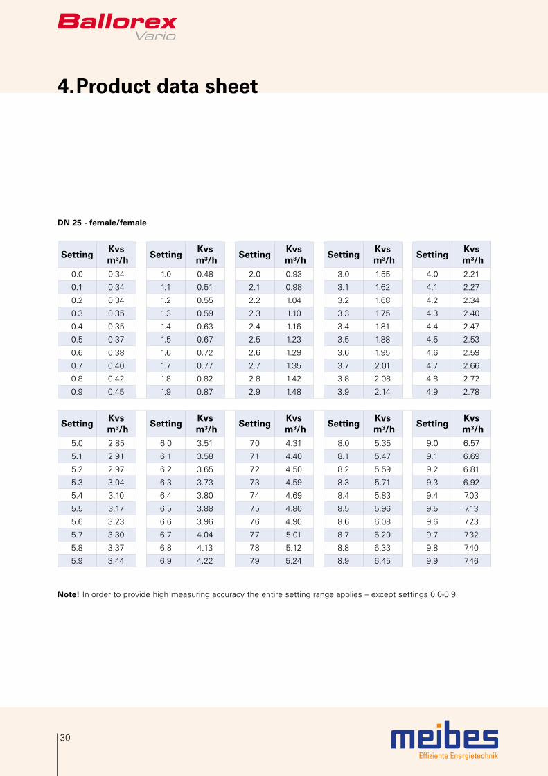
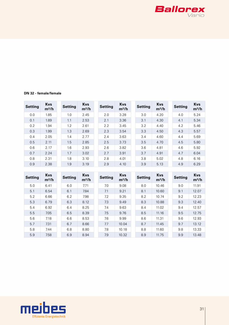
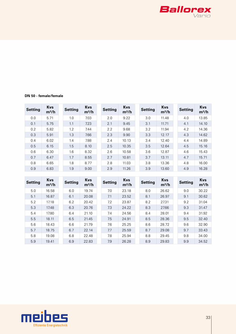
4.4 Valve settings
Kvs value and Kv values at specific valve settings refer to the pressure loss across the valve and should be used for system design and pump sizing.
DN 10 - female/female
SettingKvs
m³/hSetting
Kvs m³/h
SettingKvs
m³/hSetting
Kvs m³/h
SettingKvs
m³/h0.0 0.065 1.0 0.144 2.0 0.227 3.0 0.311 4.0 0.392
0.1 0.073 1.1 0.152 2.1 0.235 3.1 0.319 4.1 0.400
0.2 0.080 1.2 0.160 2.2 0.244 3.2 0.328 4.2 0.407
0.3 0.088 1.3 0.168 2.3 0.252 3.3 0.336 4.3 0.415
0.4 0.096 1.4 0.177 2.4 0.261 3.4 0.344 4.4 0.423
0.5 0.104 1.5 0.185 2.5 0.269 3.5 0.352 4.5 0.430
0.6 0.112 1.6 0.193 2.6 0.277 3.6 0.360 4.6 0.438
0.7 0.120 1.7 0.202 2.7 0.286 3.7 0.368 4.7 0.445
0.8 0.128 1.8 0.210 2.8 0.294 3.8 0.376 4.8 0.452
0.9 0.136 1.9 0.218 2.9 0.303 3.9 0.384 4.9 0.459
SettingKvs
m³/hSetting
Kvs m³/h
SettingKvs
m³/hSetting
Kvs m³/h
SettingKvs
m³/h5.0 0.466 6.0 0.530 7.0 0.582 8.0 0.622 9.0 0.652
5.1 0.473 6.1 0.536 7.1 0.586 8.1 0.625 9.1 0.654
5.2 0.480 6.2 0.541 7.2 0.591 8.2 0.628 9.2 0.657
5.3 0.486 6.3 0.547 7.3 0.595 8.3 0.631 9.3 0.660
5.4 0.493 6.4 0.552 7.4 0.599 8.4 0.635 9.4 0.662
5.5 0.499 6.5 0.557 7.5 0.603 8.5 0.638 9.5 0.665
5.6 0.506 6.6 0.563 7.6 0.607 8.6 0.641 9.6 0.668
5.7 0.512 6.7 0.568 7.7 0.611 8.7 0.643 9.7 0.670
5.8 0.518 6.8 0.572 7.8 0.614 8.8 0.646 9.8 0.673
5.9 0.524 6.9 0.577 7.9 0.618 8.9 0.649 9.9 0.675
Note! In order to provide high measuring accuracy the entire setting range applies – except settings 0.0-0.9.

Effiziente Energietechnik
28
4. Product data sheet
DN 15 - female/female
SettingKvs
m³/hSetting
Kvs m³/h
SettingKvs
m³/hSetting
Kvs m³/h
SettingKvs
m³/h0.0 0.07 1.0 0.11 2.0 0.25 3.0 0.40 4.0 0.55
0.1 0.07 1.1 0.12 2.1 0.26 3.1 0.41 4.1 0.57
0.2 0.06 1.2 0.13 2.2 0.28 3.2 0.43 4.2 0.58
0.3 0.06 1.3 0.15 2.3 0.29 3.3 0.44 4.3 0.60
0.4 0.07 1.4 0.16 2.4 0.31 3.4 0.46 4.4 0.62
0.5 0.07 1.5 0.17 2.5 0.32 3.5 0.47 4.5 0.63
0.6 0.08 1.6 0.19 2.6 0.34 3.6 0.49 4.6 0.65
0.7 0.08 1.7 0.20 2.7 0.35 3.7 0.50 4.7 0.67
0.8 0.09 1.8 0.22 2.8 0.37 3.8 0.52 4.8 0.68
0.9 0.10 1.9 0.23 2.9 0.38 3.9 0.53 4.9 0.70
SettingKvs
m³/hSetting
Kvs m³/h
SettingKvs
m³/hSetting
Kvs m³/h
SettingKvs
m³/h5.0 0.72 6.0 0.91 7.0 1.13 8.0 1.35 9.0 1.55
5.1 0.74 6.1 0.93 7.1 1.15 8.1 1.37 9.1 1.57
5.2 0.76 6.2 0.96 7.2 1.18 8.2 1.40 9.2 1.59
5.3 0.77 6.3 0.98 7.3 1.20 8.3 1.42 9.3 1.61
5.4 0.79 6.4 1.00 7.4 1.22 8.4 1.44 9.4 1.63
5.5 0.81 6.5 1.02 7.5 1.24 8.5 1.46 9.5 1.64
5.6 0.83 6.6 1.04 7.6 1.27 8.6 1.48 9.6 1.66
5.7 0.85 6.7 1.06 7.7 1.29 8.7 1.50 9.7 1.68
5.8 0.87 6.8 1.09 7.8 1.31 8.8 1.52 9.8 1.69
5.9 0.89 6.9 1.11 7.9 1.33 8.9 1.54 9.9 1.71
Note! In order to provide high measuring accuracy the entire setting range applies – except settings 0.0-0.9.

Effiziente Energietechnik
29
DN 20 - female/female
SettingKvs
m³/hSetting
Kvs m³/h
SettingKvs
m³/hSetting
Kvs m³/h
SettingKvs
m³/h0.0 0.12 1.0 0.31 2.0 0.64 3.0 0.98 4.0 1.33
0.1 0.13 1.1 0.34 2.1 0.67 3.1 1.02 4.1 1.37
0.2 0.14 1.2 0.37 2.2 0.70 3.2 1.05 4.2 1.40
0.3 0.16 1.3 0.40 2.3 0.74 3.3 1.09 4.3 1.44
0.4 0.17 1.4 0.44 2.4 0.77 3.4 1.12 4.4 1.48
0.5 0.19 1.5 0.47 2.5 0.81 3.5 1.16 4.5 1.51
0.6 0.21 1.6 0.50 2.6 0.84 3.6 1.19 4.6 1.55
0.7 0.24 1.7 0.53 2.7 0.88 3.7 1.23 4.7 1.59
0.8 0.26 1.8 0.57 2.8 0.91 3.8 1.26 4.8 1.63
0.9 0.29 1.9 0.60 2.9 0.95 3.9 1.30 4.9 1.66
SettingKvs
m³/hSetting
Kvs m³/h
SettingKvs
m³/hSetting
Kvs m³/h
SettingKvs
m³/h5.0 1.70 6.0 2.13 7.0 2.63 8.0 3.20 9.0 3.82
5.1 1.74 6.1 2.18 7.1 2.68 8.1 3.26 9.1 3.88
5.2 1.78 6.2 2.22 7.2 2.74 8.2 3.32 9.2 3.95
5.3 1.82 6.3 2.27 7.3 2.79 8.3 3.38 9.3 4.01
5.4 1.87 6.4 2.32 7.4 2.85 8.4 3.44 9.4 4.08
5.5 1.91 6.5 2.37 7.5 2.91 8.5 3.50 9.5 4.14
5.6 1.95 6.6 2.42 7.6 2.96 8.6 3.57 9.6 4.21
5.7 1.99 6.7 2.47 7.7 3.02 8.7 3.63 9.7 4.27
5.8 2.04 6.8 2.52 7.8 3.08 8.8 3.69 9.8 4.34
5.9 2.08 6.9 2.57 7.9 3.14 8.9 3.76 9.9 4.40
Note! In order to provide high measuring accuracy the entire setting range applies – except settings 0.0-0.9.
Effiziente Energietechnik
30
4. Product data sheet
DN 25 - female/female
SettingKvs
m³/hSetting
Kvs m³/h
SettingKvs
m³/hSetting
Kvs m³/h
SettingKvs
m³/h0.0 0.34 1.0 0.48 2.0 0.93 3.0 1.55 4.0 2.21
0.1 0.34 1.1 0.51 2.1 0.98 3.1 1.62 4.1 2.27
0.2 0.34 1.2 0.55 2.2 1.04 3.2 1.68 4.2 2.34
0.3 0.35 1.3 0.59 2.3 1.10 3.3 1.75 4.3 2.40
0.4 0.35 1.4 0.63 2.4 1.16 3.4 1.81 4.4 2.47
0.5 0.37 1.5 0.67 2.5 1.23 3.5 1.88 4.5 2.53
0.6 0.38 1.6 0.72 2.6 1.29 3.6 1.95 4.6 2.59
0.7 0.40 1.7 0.77 2.7 1.35 3.7 2.01 4.7 2.66
0.8 0.42 1.8 0.82 2.8 1.42 3.8 2.08 4.8 2.72
0.9 0.45 1.9 0.87 2.9 1.48 3.9 2.14 4.9 2.78
SettingKvs
m³/hSetting
Kvs m³/h
SettingKvs
m³/hSetting
Kvs m³/h
SettingKvs
m³/h5.0 2.85 6.0 3.51 7.0 4.31 8.0 5.35 9.0 6.57
5.1 2.91 6.1 3.58 7.1 4.40 8.1 5.47 9.1 6.69
5.2 2.97 6.2 3.65 7.2 4.50 8.2 5.59 9.2 6.81
5.3 3.04 6.3 3.73 7.3 4.59 8.3 5.71 9.3 6.92
5.4 3.10 6.4 3.80 7.4 4.69 8.4 5.83 9.4 7.03
5.5 3.17 6.5 3.88 7.5 4.80 8.5 5.96 9.5 7.13
5.6 3.23 6.6 3.96 7.6 4.90 8.6 6.08 9.6 7.23
5.7 3.30 6.7 4.04 7.7 5.01 8.7 6.20 9.7 7.32
5.8 3.37 6.8 4.13 7.8 5.12 8.8 6.33 9.8 7.40
5.9 3.44 6.9 4.22 7.9 5.24 8.9 6.45 9.9 7.46
Note! In order to provide high measuring accuracy the entire setting range applies – except settings 0.0-0.9.
Effiziente Energietechnik
31
DN 32 - female/female
SettingKvs
m³/hSetting
Kvs m³/h
SettingKvs
m³/hSetting
Kvs m³/h
SettingKvs
m³/h0.0 1.85 1.0 2.45 2.0 3.28 3.0 4.20 4.0 5.24
0.1 1.89 1.1 2.53 2.1 3.36 3.1 4.30 4.1 5.34
0.2 1.94 1.2 2.61 2.2 3.45 3.2 4.40 4.2 5.46
0.3 1.99 1.3 2.69 2.3 3.54 3.3 4.50 4.3 5.57
0.4 2.05 1.4 2.77 2.4 3.63 3.4 4.60 4.4 5.69
0.5 2.11 1.5 2.85 2.5 3.73 3.5 4.70 4.5 5.80
0.6 2.17 1.6 2.93 2.6 3.82 3.6 4.81 4.6 5.92
0.7 2.24 1.7 3.02 2.7 3.91 3.7 4.91 4.7 6.04
0.8 2.31 1.8 3.10 2.8 4.01 3.8 5.02 4.8 6.16
0.9 2.38 1.9 3.19 2.9 4.10 3.9 5.13 4.9 6.29
SettingKvs
m³/hSetting
Kvs m³/h
SettingKvs
m³/hSetting
Kvs m³/h
SettingKvs
m³/h5.0 6.41 6.0 7.71 7.0 9.08 8.0 10.46 9.0 11.91
5.1 6.54 6.1 7.84 7.1 9.21 8.1 10.60 9.1 12.07
5.2 6.66 6.2 7.98 7.2 9.35 8.2 10.74 9.2 12.23
5.3 6.79 6.3 8.12 7.3 9.49 8.3 10.88 9.3 12.40
5.4 6.92 6.4 8.25 7.4 9.63 8.4 11.02 9.4 12.57
5.5 7.05 6.5 8.39 7.5 9.76 8.5 11.16 9.5 12.75
5.6 7.18 6.6 8.53 7.6 9.99 8.6 11.31 9.6 12.93
5.7 7.31 6.7 8.66 7.7 10.04 8.7 11.45 9.7 13.12
5.8 7.44 6.8 8.80 7.8 10.18 8.8 11.60 9.8 13.33
5.9 7.58 6.9 8.94 7.9 10.32 8.9 11.75 9.9 13.48

Effiziente Energietechnik
32
4. Product data sheet
DN 40 - female/female
SettingKvs
m³/hSetting
Kvs m³/h
SettingKvs
m³/hSetting
Kvs m³/h
SettingKvs
m³/h0.0 2.70 1.0 3.57 2.0 4.96 3.0 6.64 4.0 8.45
0.1 2.75 1.1 3.69 2.1 5.12 3.1 6.82 4.1 8.63
0.2 2.82 1.2 3.81 2.2 5.28 3.2 6.99 4.2 8.82
0.3 2.89 1.3 3.94 2.3 5.44 3.3 7.17 4.3 9.01
0.4 2.97 1.4 4.08 2.4 5.61 3.4 7.35 4.4 9.20
0.5 3.05 1.5 4.22 2.5 5.78 3.5 7.53 4.5 9.39
0.6 3.14 1.6 4.36 2.6 5.95 3.6 7.71 4.6 9.58
0.7 3.24 1.7 4.51 2.7 6.12 3.7 7.90 4.7 9.77
0.8 3.34 1.8 4.65 2.8 6.29 3.8 8.08 4.8 9.96
0.9 3.45 1.9 4.81 2.9 6.46 3.9 8.26 4.9 10.15
SettingKvs
m³/hSetting
Kvs m³/h
SettingKvs
m³/hSetting
Kvs m³/h
SettingKvs
m³/h5.0 10.35 6.0 12.39 7.0 14.70 8.0 17.40 9.0 20.55
5.1 10.54 6.1 12.61 7.1 14.95 8.1 17.69 9.1 20.89
5.2 10.74 6.2 12.83 7.2 15.20 8.2 17.99 9.2 21.24
5.3 10.94 6.3 13.05 7.3 15.46 8.3 18.30 9.3 21.58
5.4 11.14 6.4 13.27 7.4 15.72 8.4 18.61 9.4 21.93
5.5 11.35 6.5 13.50 7.5 15.99 8.5 18.92 9.5 22.28
5.6 11.55 6.6 13.73 7.6 16.26 8.6 19.24 9.6 22.63
5.7 11.76 6.7 13.97 7.7 16.54 8.7 19.56 9.7 22.99
5.8 11.97 6.8 14.21 7.8 16.82 8.8 19.89 9.8 23.34
5.9 12.18 6.9 14.45 7.9 17.11 8.9 20.22 9.9 23.68
Effiziente Energietechnik
33
DN 50 - female/female
SettingKvs
m³/hSetting
Kvs m³/h
SettingKvs
m³/hSetting
Kvs m³/h
SettingKvs
m³/h0.0 5.71 1.0 7.03 2.0 9.22 3.0 11.48 4.0 13.85
0.1 5.75 1.1 7.23 2.1 9.45 3.1 11.71 4.1 14.10
0.2 5.82 1.2 7.44 2.2 9.68 3.2 11.94 4.2 14.36
0.3 5.91 1.3 7.66 2.3 9.90 3.3 12.17 4.3 14.62
0.4 6.02 1.4 7.88 2.4 10.13 3.4 12.40 4.4 14.89
0.5 6.15 1.5 8.10 2.5 10.35 3.5 12.64 4.5 15.16
0.6 6.30 1.6 8.32 2.6 10.58 3.6 12.87 4.6 15.43
0.7 6.47 1.7 8.55 2.7 10.81 3.7 13.11 4.7 15.71
0.8 6.65 1.8 8.77 2.8 11.03 3.8 13.36 4.8 16.00
0.9 6.83 1.9 9.00 2.9 11.26 3.9 13.60 4.9 16.28
SettingKvs
m³/hSetting
Kvs m³/h
SettingKvs
m³/hSetting
Kvs m³/h
SettingKvs
m³/h5.0 16.58 6.0 19.74 7.0 23.18 8.0 26.62 9.0 30.22
5.1 16.87 6.1 20.08 7.1 23.52 8.1 26.97 9.1 30.62
5.2 17.18 6.2 20.42 7.2 23.87 8.2 27.31 9.2 31.04
5.3 17.48 6.3 20.76 7.3 24.22 8.3 27.66 9.3 31.47
5.4 17.80 6.4 21.10 7.4 24.56 8.4 28.01 9.4 31.92
5.5 18.11 6.5 21.45 7.5 24.91 8.5 28.36 9.5 32.40
5.6 18.43 6.6 21.79 7.6 25.25 8.6 28.72 9.6 32.90
5.7 18.75 6.7 22.14 7.7 25.59 8.7 29.08 9.7 33.43
5.8 19.08 6.8 22.48 7.8 25.94 8.8 29.45 9.8 34.00
5.9 19.41 6.9 22.83 7.9 26.28 8.9 29.83 9.9 34.52
Effiziente Energietechnik
34
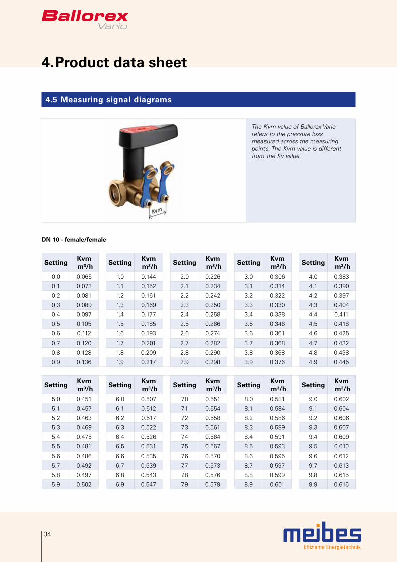
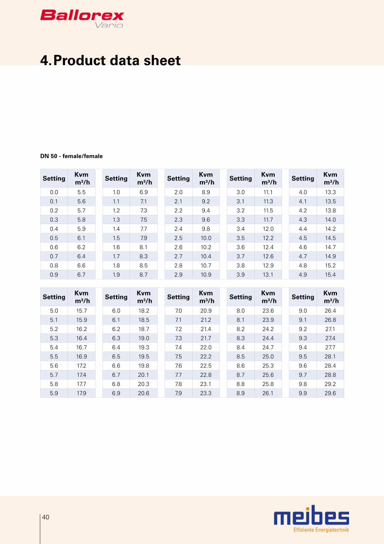
4. Product data sheet
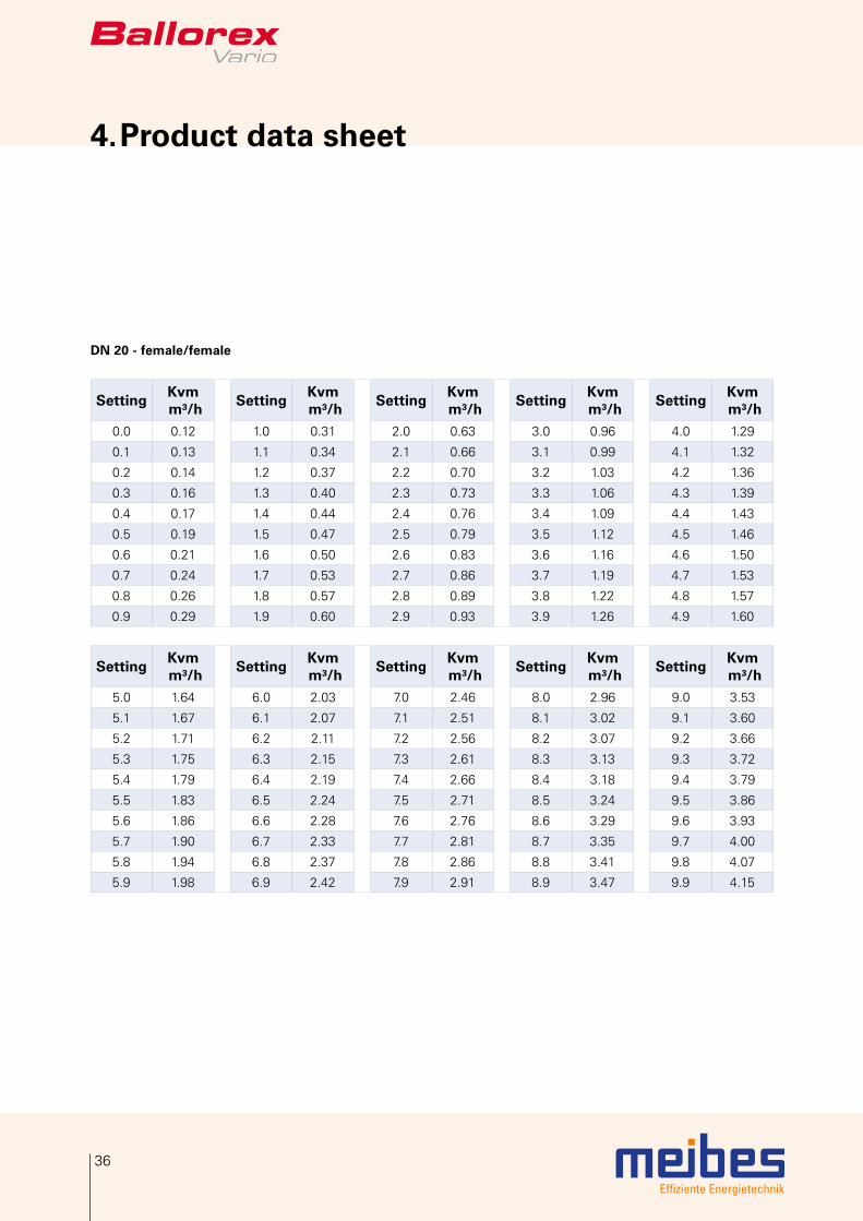
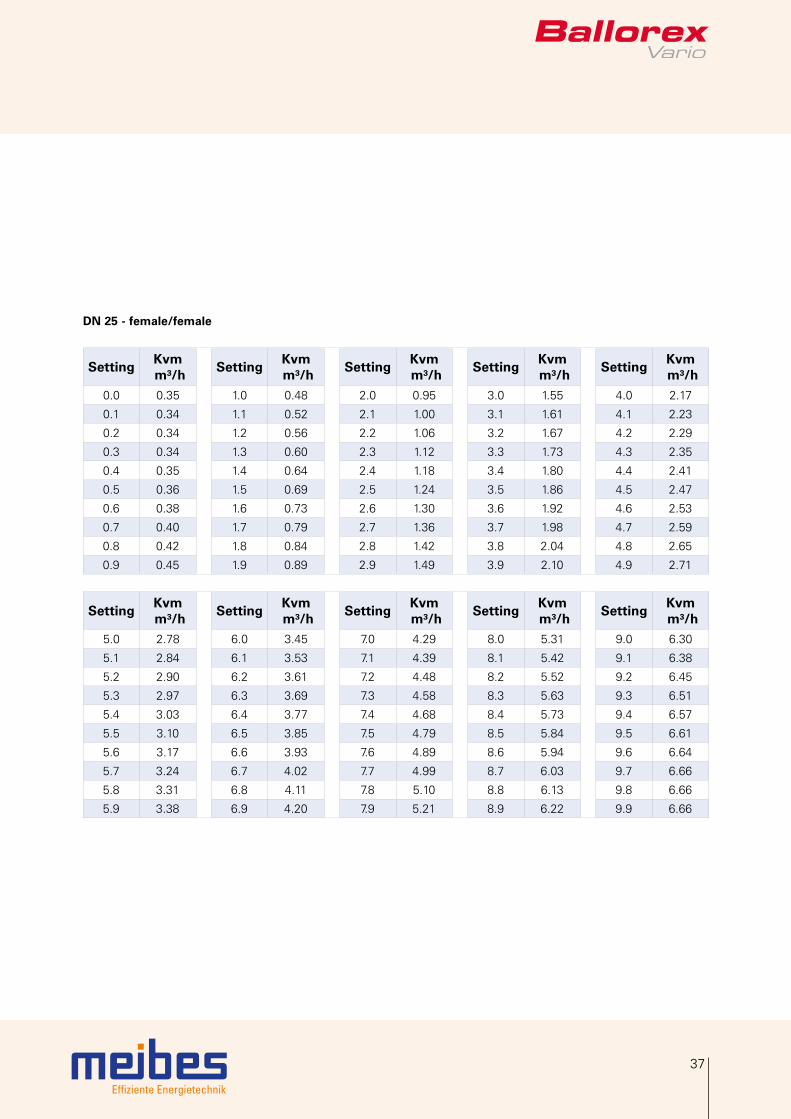
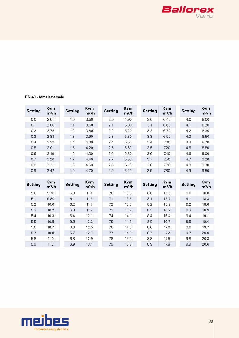
4.5 Measuring signal diagrams
The Kvm value of Ballorex Vario refers to the pressure loss measured across the measuring points. The Kvm value is different from the Kv value.
DN 10 - female/female
SettingKvm m³/h
SettingKvm m³/h
SettingKvm m³/h
SettingKvm m³/h
SettingKvm m³/h
0.0 0.065 1.0 0.144 2.0 0.226 3.0 0.306 4.0 0.383
0.1 0.073 1.1 0.152 2.1 0.234 3.1 0.314 4.1 0.390
0.2 0.081 1.2 0.161 2.2 0.242 3.2 0.322 4.2 0.397
0.3 0.089 1.3 0.169 2.3 0.250 3.3 0.330 4.3 0.404
0.4 0.097 1.4 0.177 2.4 0.258 3.4 0.338 4.4 0.411
0.5 0.105 1.5 0.185 2.5 0.266 3.5 0.346 4.5 0.418
0.6 0.112 1.6 0.193 2.6 0.274 3.6 0.361 4.6 0.425
0.7 0.120 1.7 0.201 2.7 0.282 3.7 0.368 4.7 0.432
0.8 0.128 1.8 0.209 2.8 0.290 3.8 0.368 4.8 0.438
0.9 0.136 1.9 0.217 2.9 0.298 3.9 0.376 4.9 0.445
SettingKvm m³/h
SettingKvm m³/h
SettingKvm m³/h
SettingKvm m³/h
SettingKvm m³/h
5.0 0.451 6.0 0.507 7.0 0.551 8.0 0.581 9.0 0.602
5.1 0.457 6.1 0.512 7.1 0.554 8.1 0.584 9.1 0.604
5.2 0.463 6.2 0.517 7.2 0.558 8.2 0.586 9.2 0.606
5.3 0.469 6.3 0.522 7.3 0.561 8.3 0.589 9.3 0.607
5.4 0.475 6.4 0.526 7.4 0.564 8.4 0.591 9.4 0.609
5.5 0.481 6.5 0.531 7.5 0.567 8.5 0.593 9.5 0.610
5.6 0.486 6.6 0.535 7.6 0.570 8.6 0.595 9.6 0.612
5.7 0.492 6.7 0.539 7.7 0.573 8.7 0.597 9.7 0.613
5.8 0.497 6.8 0.543 7.8 0.576 8.8 0.599 9.8 0.615
5.9 0.502 6.9 0.547 7.9 0.579 8.9 0.601 9.9 0.616

Effiziente Energietechnik
35
DN 15 - female/female
SettingKvm m³/h
SettingKvm m³/h
SettingKvm m³/h
SettingKvm m³/h
SettingKvm m³/h
0.0 0.07 1.0 0.11 2.0 0.25 3.0 0.39 4.0 0.54
0.1 0.07 1.1 0.12 2.1 0.26 3.1 0.41 4.1 0.56
0.2 0.06 1.2 0.13 2.2 0.28 3.2 0.42 4.2 0.57
0.3 0.06 1.3 0.15 2.3 0.29 3.3 0.44 4.3 0.59
0.4 0.07 1.4 0.16 2.4 0.31 3.4 0.45 4.4 0.61
0.5 0.07 1.5 0.17 2.5 0.32 3.5 0.47 4.5 0.62
0.6 0.08 1.6 0.19 2.6 0.34 3.6 0.48 4.6 0.64
0.7 0.08 1.7 0.20 2.7 0.35 3.7 0.50 4.7 0.65
0.8 0.09 1.8 0.22 2.8 0.37 3.8 0.51 4.8 0.67
0.9 0.10 1.9 0.23 2.9 0.38 3.9 0.53 4.9 0.69
SettingKvm m³/h
SettingKvm m³/h
SettingKvm m³/h
SettingKvm m³/h
SettingKvm m³/h
5.0 0.70 6.0 0.88 7.0 1.09 8.0 1.29 9.0 1.48
5.1 0.72 6.1 0.90 7.1 1.11 8.1 1.31 9.1 1.49
5.2 0.74 6.2 0.92 7.2 1.13 8.2 1.33 9.2 1.51
5.3 0.76 6.3 0.94 7.3 1.15 8.3 1.35 9.3 1.53
5.4 0.77 6.4 0.96 7.4 1.17 8.4 1.37 9.4 1.54
5.5 0.79 6.5 0.98 7.5 1.19 8.5 1.39 9.5 1.56
5.6 0.81 6.6 1.00 7.6 1.21 8.6 1.41 9.6 1.57
5.7 0.83 6.7 1.03 7.7 1.23 8.7 1.43 9.7 1.58
5.8 0.85 6.8 1.05 7.8 1.25 8.8 1.44 9.8 1.60
5.9 0.87 6.9 1.07 7.9 1.27 8.9 1.46 9.9 1.61
Effiziente Energietechnik
36
4. Product data sheet
DN 20 - female/female
SettingKvm m³/h
SettingKvm m³/h
SettingKvm m³/h
SettingKvm m³/h
SettingKvm m³/h
0.0 0.12 1.0 0.31 2.0 0.63 3.0 0.96 4.0 1.29
0.1 0.13 1.1 0.34 2.1 0.66 3.1 0.99 4.1 1.32
0.2 0.14 1.2 0.37 2.2 0.70 3.2 1.03 4.2 1.36
0.3 0.16 1.3 0.40 2.3 0.73 3.3 1.06 4.3 1.39
0.4 0.17 1.4 0.44 2.4 0.76 3.4 1.09 4.4 1.43
0.5 0.19 1.5 0.47 2.5 0.79 3.5 1.12 4.5 1.46
0.6 0.21 1.6 0.50 2.6 0.83 3.6 1.16 4.6 1.50
0.7 0.24 1.7 0.53 2.7 0.86 3.7 1.19 4.7 1.53
0.8 0.26 1.8 0.57 2.8 0.89 3.8 1.22 4.8 1.57
0.9 0.29 1.9 0.60 2.9 0.93 3.9 1.26 4.9 1.60
SettingKvm m³/h
SettingKvm m³/h
SettingKvm m³/h
SettingKvm m³/h
SettingKvm m³/h
5.0 1.64 6.0 2.03 7.0 2.46 8.0 2.96 9.0 3.53
5.1 1.67 6.1 2.07 7.1 2.51 8.1 3.02 9.1 3.60
5.2 1.71 6.2 2.11 7.2 2.56 8.2 3.07 9.2 3.66
5.3 1.75 6.3 2.15 7.3 2.61 8.3 3.13 9.3 3.72
5.4 1.79 6.4 2.19 7.4 2.66 8.4 3.18 9.4 3.79
5.5 1.83 6.5 2.24 7.5 2.71 8.5 3.24 9.5 3.86
5.6 1.86 6.6 2.28 7.6 2.76 8.6 3.29 9.6 3.93
5.7 1.90 6.7 2.33 7.7 2.81 8.7 3.35 9.7 4.00
5.8 1.94 6.8 2.37 7.8 2.86 8.8 3.41 9.8 4.07
5.9 1.98 6.9 2.42 7.9 2.91 8.9 3.47 9.9 4.15
Effiziente Energietechnik
37
DN 25 - female/female
SettingKvm m³/h
SettingKvm m³/h
SettingKvm m³/h
SettingKvm m³/h
SettingKvm m³/h
0.0 0.35 1.0 0.48 2.0 0.95 3.0 1.55 4.0 2.17
0.1 0.34 1.1 0.52 2.1 1.00 3.1 1.61 4.1 2.23
0.2 0.34 1.2 0.56 2.2 1.06 3.2 1.67 4.2 2.29
0.3 0.34 1.3 0.60 2.3 1.12 3.3 1.73 4.3 2.35
0.4 0.35 1.4 0.64 2.4 1.18 3.4 1.80 4.4 2.41
0.5 0.36 1.5 0.69 2.5 1.24 3.5 1.86 4.5 2.47
0.6 0.38 1.6 0.73 2.6 1.30 3.6 1.92 4.6 2.53
0.7 0.40 1.7 0.79 2.7 1.36 3.7 1.98 4.7 2.59
0.8 0.42 1.8 0.84 2.8 1.42 3.8 2.04 4.8 2.65
0.9 0.45 1.9 0.89 2.9 1.49 3.9 2.10 4.9 2.71
SettingKvm m³/h
SettingKvm m³/h
SettingKvm m³/h
SettingKvm m³/h
SettingKvm m³/h
5.0 2.78 6.0 3.45 7.0 4.29 8.0 5.31 9.0 6.30
5.1 2.84 6.1 3.53 7.1 4.39 8.1 5.42 9.1 6.38
5.2 2.90 6.2 3.61 7.2 4.48 8.2 5.52 9.2 6.45
5.3 2.97 6.3 3.69 7.3 4.58 8.3 5.63 9.3 6.51
5.4 3.03 6.4 3.77 7.4 4.68 8.4 5.73 9.4 6.57
5.5 3.10 6.5 3.85 7.5 4.79 8.5 5.84 9.5 6.61
5.6 3.17 6.6 3.93 7.6 4.89 8.6 5.94 9.6 6.64
5.7 3.24 6.7 4.02 7.7 4.99 8.7 6.03 9.7 6.66
5.8 3.31 6.8 4.11 7.8 5.10 8.8 6.13 9.8 6.66
5.9 3.38 6.9 4.20 7.9 5.21 8.9 6.22 9.9 6.66

Effiziente Energietechnik
38
4. Product data sheet
DN 32 - female/female
SettingKvm m³/h
SettingKvm m³/h
SettingKvm m³/h
SettingKvm m³/h
SettingKvm m³/h
0.0 1.81 1.0 2.42 2.0 3.21 3.0 4.06 4.0 5.00
0.1 1.85 1.1 2.49 2.1 3.29 3.1 4.15 4.1 5.10
0.2 1.90 1.2 2.57 2.2 3.37 3.2 4.24 4.2 5.20
0.3 1.96 1.3 2.64 2.3 3.46 3.3 4.33 4.3 5.30
0.4 2.02 1.4 2.72 2.4 3.54 3.4 4.42 4.4 5.40
0.5 2.08 1.5 2.80 2.5 3.63 3.5 4.51 4.5 5.50
0.6 2.14 1.6 2.88 2.6 3.71 3.6 4.61 4.6 5.60
0.7 2.21 1.7 2.96 2.7 3.80 3.7 4.70 4.7 5.70
0.8 2.28 1.8 3.04 2.8 3.89 3.8 4.79 4.8 5.80
0.9 2.35 1.9 3.12 2.9 3.97 3.9 4.89 4.9 5.90
SettingKvm m³/h
SettingKvm m³/h
SettingKvm m³/h
SettingKvm m³/h
SettingKvm m³/h
5.0 6.00 6.0 7.10 7.0 8.30 8.0 9.50 9.0 10.8
5.1 6.10 6.1 7.20 7.1 8.40 8.1 9.60 9.1 10.9
5.2 6.20 6.2 7.30 7.2 8.50 8.2 9.70 9.2 11.0
5.3 6.30 6.3 7.50 7.3 8.60 8.3 9.90 9.3 11.1
5.4 6.40 6.4 7.60 7.4 8.80 8.4 10.0 9.4 11.3
5.5 6.50 6.5 7.70 7.5 8.90 8.5 10.1 9.5 11.4
5.6 6.70 6.6 7.80 7.6 9.00 8.6 10.2 9.6 11.6
5.7 6.80 6.7 7.90 7.7 9.10 8.7 10.4 9.7 11.7
5.8 6.90 6.8 8.00 7.8 9.30 8.8 10.5 9.8 11.9
5.9 7.00 6.9 8.20 7.9 9.40 8.9 10.6 9.9 12.0
Effiziente Energietechnik
39
DN 40 - female/female
SettingKvm m³/h
SettingKvm m³/h
SettingKvm m³/h
SettingKvm m³/h
SettingKvm m³/h
0.0 2.61 1.0 3.50 2.0 4.90 3.0 6.40 4.0 8.00
0.1 2.68 1.1 3.60 2.1 5.00 3.1 6.60 4.1 8.20
0.2 2.75 1.2 3.80 2.2 5.20 3.2 6.70 4.2 8.30
0.3 2.83 1.3 3.90 2.3 5.30 3.3 6.90 4.3 8.50
0.4 2.92 1.4 4.00 2.4 5.50 3.4 7.00 4.4 8.70
0.5 3.01 1.5 4.20 2.5 5.60 3.5 7.20 4.5 8.80
0.6 3.10 1.6 4.30 2.6 5.80 3.6 7.40 4.6 9.00
0.7 3.20 1.7 4.40 2.7 5.90 3.7 7.50 4.7 9.20
0.8 3.31 1.8 4.60 2.8 6.10 3.8 7.70 4.8 9.30
0.9 3.42 1.9 4.70 2.9 6.20 3.9 7.80 4.9 9.50
SettingKvm m³/h
SettingKvm m³/h
SettingKvm m³/h
SettingKvm m³/h
SettingKvm m³/h
5.0 9.70 6.0 11.4 7.0 13.3 8.0 15.5 9.0 18.0
5.1 9.80 6.1 11.5 7.1 13.5 8.1 15.7 9.1 18.3
5.2 10.0 6.2 11.7 7.2 13.7 8.2 15.9 9.2 18.6
5.3 10.2 6.3 11.9 7.3 13.9 8.3 16.2 9.3 18.9
5.4 10.3 6.4 12.1 7.4 14.1 8.4 16.4 9.4 19.1
5.5 10.5 6.5 12.3 7.5 14.3 8.5 16.7 9.5 19.4
5.6 10.7 6.6 12.5 7.6 14.5 8.6 17.0 9.6 19.7
5.7 10.8 6.7 12.7 7.7 14.8 8.7 17.2 9.7 20.0
5.8 11.0 6.8 12.9 7.8 15.0 8.8 17.5 9.8 20.3
5.9 11.2 6.9 13.1 7.9 15.2 8.9 17.8 9.9 20.6
Effiziente Energietechnik
40
4. Product data sheet
DN 50 - female/female
SettingKvm m³/h
SettingKvm m³/h
SettingKvm m³/h
SettingKvm m³/h
SettingKvm m³/h
0.0 5.5 1.0 6.9 2.0 8.9 3.0 11.1 4.0 13.3
0.1 5.6 1.1 7.1 2.1 9.2 3.1 11.3 4.1 13.5
0.2 5.7 1.2 7.3 2.2 9.4 3.2 11.5 4.2 13.8
0.3 5.8 1.3 7.5 2.3 9.6 3.3 11.7 4.3 14.0
0.4 5.9 1.4 7.7 2.4 9.8 3.4 12.0 4.4 14.2
0.5 6.1 1.5 7.9 2.5 10.0 3.5 12.2 4.5 14.5
0.6 6.2 1.6 8.1 2.6 10.2 3.6 12.4 4.6 14.7
0.7 6.4 1.7 8.3 2.7 10.4 3.7 12.6 4.7 14.9
0.8 6.6 1.8 8.5 2.8 10.7 3.8 12.9 4.8 15.2
0.9 6.7 1.9 8.7 2.9 10.9 3.9 13.1 4.9 15.4
SettingKvm m³/h
SettingKvm m³/h
SettingKvm m³/h
SettingKvm m³/h
SettingKvm m³/h
5.0 15.7 6.0 18.2 7.0 20.9 8.0 23.6 9.0 26.4
5.1 15.9 6.1 18.5 7.1 21.2 8.1 23.9 9.1 26.8
5.2 16.2 6.2 18.7 7.2 21.4 8.2 24.2 9.2 27.1
5.3 16.4 6.3 19.0 7.3 21.7 8.3 24.4 9.3 27.4
5.4 16.7 6.4 19.3 7.4 22.0 8.4 24.7 9.4 27.7
5.5 16.9 6.5 19.5 7.5 22.2 8.5 25.0 9.5 28.1
5.6 17.2 6.6 19.8 7.6 22.5 8.6 25.3 9.6 28.4
5.7 17.4 6.7 20.1 7.7 22.8 8.7 25.6 9.7 28.8
5.8 17.7 6.8 20.3 7.8 23.1 8.8 25.8 9.8 29.2
5.9 17.9 6.9 20.6 7.9 23.3 8.9 26.1 9.9 29.6

Effiziente Energietechnik
41
4.6 Measuring accuracy
The measuring accuracy of Ballorex Vario is variable and depends on the valve setting. A high valve setting position provides a more accurate measuring.
DN 10 - female/female
0.0 1.0 2.0 3.0 4.0 5.0 6.0 7.0 8.0 9.0 9.9
Position
Kvm deviation in %30
25
20
15
10
5
0
position 0.0-0.9
position 1.0-9.9(recommendedsetting range)
Kvm deviation atposition 2.5 (25% ofthe maximum flow)
The Ballorex Vario DN 10 conforms to the BS standard 7350:1990. At 25% of the flow range the Kvm deviation is only ±7%.
DN 15 - female/female
0.0 1.0 2.0 3.0 4.0 5.0 6.0 7.0 8.0 9.0 9.9
Position
Kvm deviation in %30
25
20
15
10
5
0
position 0.0-0.9
position 1.0-9.9(recommendedsetting range)
Kvm deviation atposition 2.5 (25% ofthe maximum flow)
The Ballorex Vario DN 15 conforms to the BS standard 7350:1990. At 25% of the flow range the Kvm deviation is only ±7%.

Effiziente Energietechnik
42
4. Product data sheet
DN 20 - female/female
0.0 1.0 2.0 3.0 4.0 5.0 6.0 7.0 8.0 9.0 9.9
Position
Kvm deviation in %14
13
12
11
10
9
8
7
6
5
4
3
2
1
0
position 0.0-0.9
position 1.0-9.9(recommendedsetting range)
Kvm deviation atposition 2.5 (25% ofthe maximum flow)
The Ballorex Vario DN 20 conforms to the BS standard 7350:1990. At 25% of the flow range the Kvm deviation is only ±5%.
DN 25 - female/female
0.0 1.0 2.0 3.0 4.0 5.0 6.0 7.0 8.0 9.0 9.9
Position
Kvm deviation in %10
9
8
7
6
5
4
3
2
1
0
position 0.0-0.9
position 1.0-9.9(recommendedsetting range)
Kvm deviation atposition 2.5 (25% ofthe maximum flow)
The Ballorex Vario DN 25 conforms to the BS standard 7350:1990. At 25% of the flow range the Kvm deviation is only ±4.5%.

Effiziente Energietechnik
43
DN 32 - female/female
0.0 1.0 2.0 3.0 4.0 5.0 6.0 7.0 8.0 9.0 9.9
Position
Kvm deviation in %10
9
8
7
6
5
4
3
2
1
0
position 1.0-9.9(recommendedsetting range)
Kvm deviation atposition 2.5 (25% ofthe maximum flow)
The Ballorex Vario DN 32 conforms to the BS standard 7350:1990. At 25% of the flow range the Kvm deviation is only ±4.7%.
DN 40 - female/female
0.0 1.0 2.0 3.0 4.0 5.0 6.0 7.0 8.0 9.0 9.9
Position
Kvm deviation in %10
9
8
7
6
5
4
3
2
1
0
position 1.0-9.9(recommendedsetting range)
Kvm deviation atposition 2.5 (25% ofthe maximum flow)
The Ballorex Vario DN 40 conforms to the BS standard 7350:1990. At 25% of the flow range the Kvm deviation is only ±4.7%.

Effiziente Energietechnik
44
4. Product data sheet
DN 50 - female/female
0.0 1.0 2.0 3.0 4.0 5.0 6.0 7.0 8.0 9.0 9.9
Position
Kvm deviation in %10
9
8
7
6
5
4
3
2
1
0
position 1.0-9.9(recommendedsetting range)
Kvm deviation atposition 2.5 (25% ofthe maximum flow)
The Ballorex Vario DN 50 conforms to the BS standard 7350:1990. At 25% of the flow range the Kvm deviation is only ±4.7%.
Note! The measuring accuracy is not affected by the flow direction through the Ballorex Vario valve.

Effiziente Energietechnik
45
5. Accessories
There is a wide range of accessories and spare parts available for Ballorex Vario valves. These comprise: insulation jackets, press adaptors, high capacity drain valve and other
Accessories Article Dimension Description
80597.7000 DN 15 Insulation jackets for Ballorex VarioMaterial: expanded polypropyleneColor: anthraciteThermal conductivity: 0,035 W/mK at 10°CApplication: up to 110°CFire protection class: B2, DIN 4102 and E, EN 13501-1
80597.7010 DN 20
80597.7020 DN 25
80597.7030 DN 32
80597.7040 DN 40
80597.7050 DN 50
80597.0001 15 mm x ½" Pre-sealed press adaptors (2 pcs)for valve DN 15 -50, max. 16 bar
80597.0002 18 mm x ½"
80597.0003 15 mm x ¾"
80597.0004 18 mm x ¾"
80597.0005 22 mm x ¾"
80597.0006 28 mm x 1"
80597.0007 35 mm x 1¼"
80597.0008 42 mm x 1½"
80597.0009 54 mm x 2"
80597.0205 DN 15High capacity drain valve (Kv 4,5) ½“ female/female threaded connection
80597.0206 DN 20 High capacity drain valve (Kv 4,5) ¾“ female/female threaded connection
80597.0207 DN 25 High capacity drain valve (Kv 4,5) 1“ female/female threaded connection
Effiziente Energietechnik
46
6. Sizing example
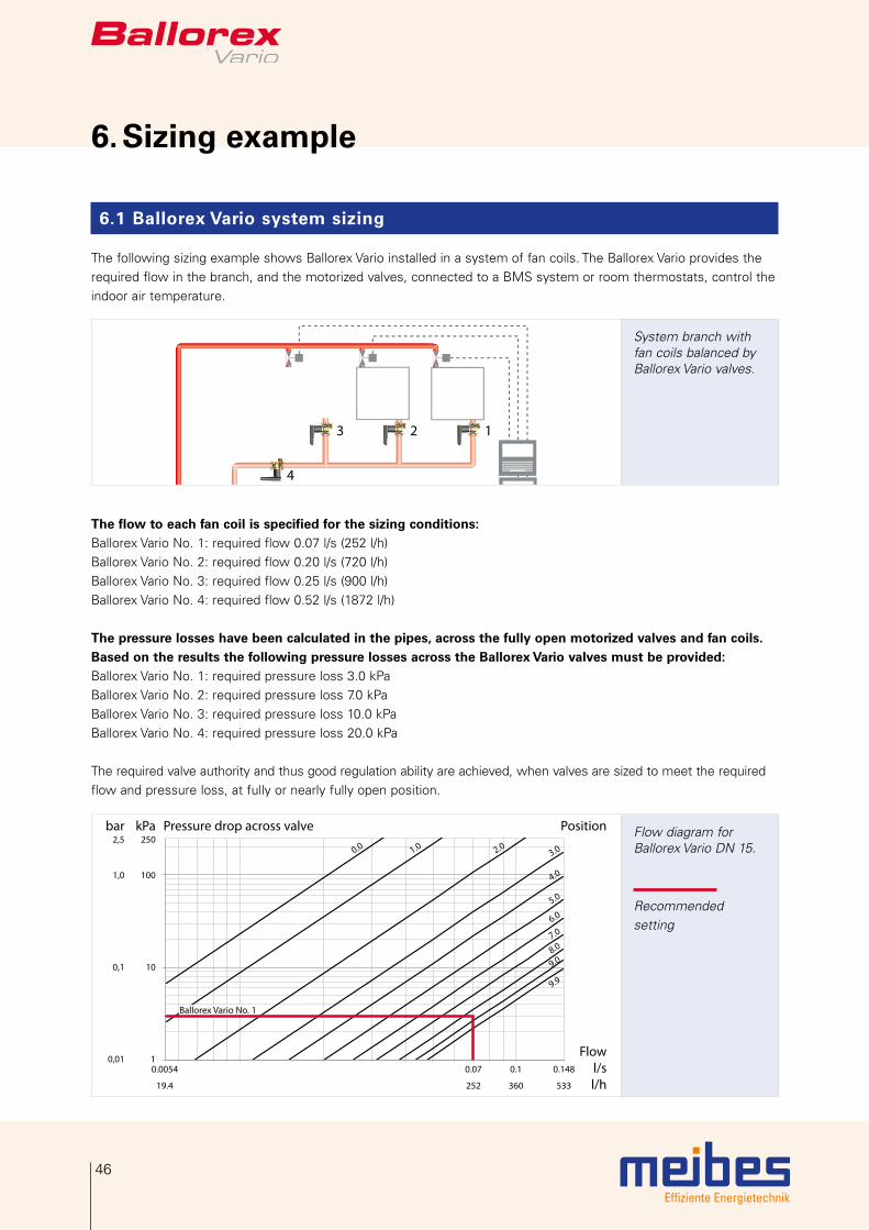
6.1 Ballorex Vario system sizing
The following sizing example shows Ballorex Vario installed in a system of fan coils. The Ballorex Vario provides the required flow in the branch, and the motorized valves, connected to a BMS system or room thermostats, control the indoor air temperature.
3 2 1
4
System branch with fan coils balanced by Ballorex Vario valves.
The flow to each fan coil is specified for the sizing conditions:Ballorex Vario No. 1: required flow 0.07 l/s (252 l/h)Ballorex Vario No. 2: required flow 0.20 l/s (720 l/h)Ballorex Vario No. 3: required flow 0.25 l/s (900 l/h)Ballorex Vario No. 4: required flow 0.52 l/s (1872 l/h)
The pressure losses have been calculated in the pipes, across the fully open motorized valves and fan coils. Based on the results the following pressure losses across the Ballorex Vario valves must be provided:Ballorex Vario No. 1: required pressure loss 3.0 kPaBallorex Vario No. 2: required pressure loss 7.0 kPaBallorex Vario No. 3: required pressure loss 10.0 kPaBallorex Vario No. 4: required pressure loss 20.0 kPa
The required valve authority and thus good regulation ability are achieved, when valves are sized to meet the required flow and pressure loss, at fully or nearly fully open position.
Pressure drop across valve PositionkPa250
100
10
1
bar2,5
1,0
0,1
0,01Flow
l/sl/h
Ballorex Vario No. 1
0.0054 0.07 0.1 0.148
19.4 252 360 533
9.9
9.08.07.06.0
5.0
4.0
3.02.01.00.0Flow diagram for Ballorex Vario DN 15.
Recommended setting

Effiziente Energietechnik
47
The smallest size Ballorex Vario meeting the requirements is selected for each system circuit. In this case a DN 15 valve at setting 8.5 will reach the required flow of 0.07 l/s and the required pressure loss of 3.0 kPa. This valve size will provide good regulation as any setting change will result in a greater pressure loss than for example in the case of a DN 20 valve. It is therefor easier to adjust a DN 15 valve than a DN 20 valve to the desired flow (see the next-graph at the end of this page).
The Ballorex Vario DN 15 setting range for 0.7 l/s flow is 9.9 - 1.4 = 8.5The Ballorex Vario DN 20 setting range for 0.7 l/s flow is 6.8 - 1.0 = 5.8The DN 15 valve is preferred as it is easier to set the valve to the required flow comparred to the DN 20 valve due tothe higher setting resolution.
Pressure drop across valve PositionkPa250
100
10
7
3
1
bar2.5
1.0
0.1
0.07
0.03
0.01Flow
l/sl/h
9.99.08.07.06.0
5.0
4.0
3.02.01.00.0
Ballorex Vario No. 3
Ballorex Vario No. 2
Ballorex Vario No. 1
0.0153 0.7 0.1 0.2 0.25 0.325
55 252 360 720 900 1170
Flow diagram for Ballorex Vario DN 20.
Not recommendedsetting
Recommended set-ting
Pressure drop across valve PositionkPa250
100
20
10
1
bar2.5
1.0
0.1
0.01Flow
l/sl/h
9.9
9.0
8.0
7.06.05.0
4.0
3.02.01.00.0
Ballorex Vario No. 4
0.0232 0.05 0.1 0.2 0.3 0.4 0.52 0.603
83.5 180 360 720 1080 1440 1872 2171
Flow diagram for Ballorex Vario DN 25.
Recommended setting
For the 0.20 l/s and 0.25 l/s flow Ballorex Vario DN 20 is selected and for the 0.52 l/s flow Ballorex Vario DN 25 is selected.
Effiziente Energietechnik
48
6. Sizing example
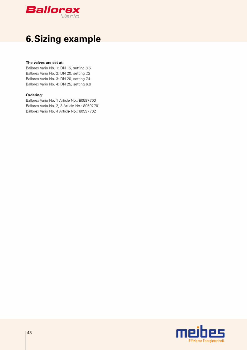
The valves are set at:Ballorex Vario No. 1: DN 15, setting 8.5Ballorex Vario No. 2: DN 20, setting 7.2Ballorex Vario No. 3: DN 20, setting 7.4Ballorex Vario No. 4: DN 25, setting 6.9
Ordering:Ballorex Vario No. 1 Article No.: 80597.700Ballorex Vario No. 2, 3 Article No.: 80597.701Ballorex Vario No. 4 Article No.: 80597.702
Effiziente Energietechnik
49
6.2 General specifications DN 10-50
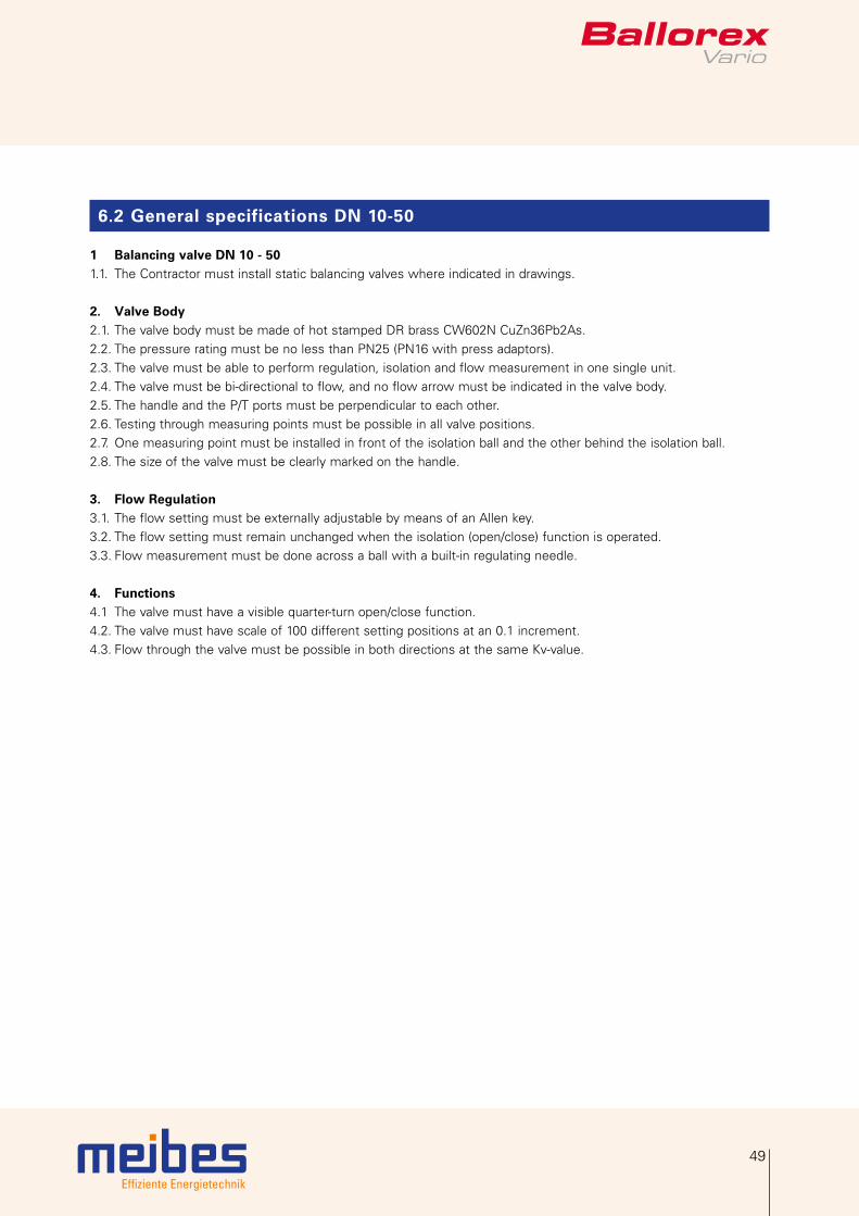
1 Balancing valve DN 10 - 501.1. The Contractor must install static balancing valves where indicated in drawings.
2. Valve Body2.1. The valve body must be made of hot stamped DR brass CW602N CuZn36Pb2As.2.2. The pressure rating must be no less than PN25 (PN16 with press adaptors).2.3. The valve must be able to perform regulation, isolation and flow measurement in one single unit.2.4. The valve must be bi-directional to flow, and no flow arrow must be indicated in the valve body.2.5. The handle and the P/T ports must be perpendicular to each other.2.6. Testing through measuring points must be possible in all valve positions.2.7. One measuring point must be installed in front of the isolation ball and the other behind the isolation ball.2.8. The size of the valve must be clearly marked on the handle.
3. Flow Regulation3.1. The flow setting must be externally adjustable by means of an Allen key.3.2. The flow setting must remain unchanged when the isolation (open/close) function is operated.3.3. Flow measurement must be done across a ball with a built-in regulating needle.
4. Functions4.1 The valve must have a visible quarter-turn open/close function.4.2. The valve must have scale of 100 different setting positions at an 0.1 increment.4.3. Flow through the valve must be possible in both directions at the same Kv-value.
Effiziente EnergietechnikEffiziente Energietechnik
50
Notes
50

Effiziente Energietechnik
Contact
Contact data
GermanyMeibes System-Technik GmbHRingstrasse 18D-04827 Gerichshainwww.meibes.de

Effiziente Energietechnik
meibes System-Technik GmbH · Ringstraße 18 · D-04827 Gerichshain
Tel. + 49(0) 3 42 92 7 13-0 · Telefax + 49(0) 3 42 92 7 13-50
[email protected] · www.meibes.de
meibes-group
2400
2.41
5 V
alid
sin
ce 2
8-07
-201
5
Sub
ject
to
tech
nica
l mod
ifica
tions