double d trailers p.o. box 336 highway 11 pink hill, nc
TRANSCRIPT
Double D Trailers P.O. Box 336 Highway 11
Pink Hill, NC 28572 252-568-4042 Phone
252-568-4958 Facsimile www.doubledtrailers.com
This manual contains safety information and operational instructions for your trailer. You must read this manual before using your trailer. You must follow all safety precautions and instructions.
^ Warning
Table of Contents
i
1. INTRODUCTION AND WARRANTY..................................................................................1 1.1. Introduction................................................................................................................................................... 1 1.2. Warranty ....................................................................................................................................................... 2
2. SAFETY .............................................................................................................................4 2.1. Safety Alert Symbols and Signal Words....................................................................................................... 4 2.2. Towing Hazards............................................................................................................................................ 4
2.2.1. Inadequate Tow Vehicle ....................................................................................................................... 4 2.2.2. Driving Too Fast For Conditions........................................................................................................... 4 2.2.3. Changed Handling With a Trailer ......................................................................................................... 5 2.2.4. Trailer Not Properly Coupled to the Hitch............................................................................................. 5 2.2.5. Connection Of Safety Chains ............................................................................................................... 5 2.2.6. Connection of Breakaway Brake .......................................................................................................... 5 2.2.7. Mismatch Between Trailer and Hitch.................................................................................................... 6 2.2.8. Inspect Tires, Wheels and Lug Nuts..................................................................................................... 6 2.2.9. Overloading .......................................................................................................................................... 6 2.2.10. Improper Load Distribution ................................................................................................................... 7 2.2.11. Shifting Cargo....................................................................................................................................... 7 2.2.12. Inappropriate Cargo.............................................................................................................................. 7 2.2.13. Brakes, Lights or Mirrors....................................................................................................................... 7 2.2.14. Hazards From Modifying Your Trailer................................................................................................... 8 2.2.15. Hazards to Horses................................................................................................................................ 8 2.2.16. Hazards to Livestock ............................................................................................................................ 8 2.2.17. Hazards from Accessories.................................................................................................................... 8 2.2.18. Safety Warning Labels on Your Trailer................................................................................................. 9 2.2.19. Reporting Safety Defects...................................................................................................................... 9
3. TIRE SAFETY INFORMATION ........................................................................................10 3.1. Steps for Determining Correct Load Limit – Trailer .................................................................................... 10
3.1.1. Trailers 10,000 Pounds GVWR or Less ............................................................................................. 10 3.1.2. Trailers Over 10,000 Pounds GVWR ................................................................................................. 10
3.2. Glossary Of Tire Terminology..................................................................................................................... 10 3.3. Tire Safety - Everything Rides On It ........................................................................................................... 12
3.3.1. Safety First–Basic Tire Maintenance.................................................................................................. 13 3.3.2. Finding Your Vehicle's Recommended Tire Pressure and Load Limits.............................................. 13 3.3.3. Understanding Tire Pressure and Load Limits ................................................................................... 13 3.3.4. Checking Tire Pressure ...................................................................................................................... 13 3.3.5. Steps for Maintaining Proper Tire Pressure ....................................................................................... 14 3.3.6. Tire Size.............................................................................................................................................. 14 3.3.7. Tire Tread ........................................................................................................................................... 14 3.3.8. Tire Balance and Wheel Alignment .................................................................................................... 14 3.3.9. Tire Repair .......................................................................................................................................... 14 3.3.10. Tire Fundamentals.............................................................................................................................. 14
3.3.10.1. Information on Passenger Vehicle Tires..................................................................................... 15 3.3.10.2. UTQGS Information.................................................................................................................... 15 3.3.10.3. Additional Information on Light Truck Tires ................................................................................ 16
3.3.11. Tire Safety Tips................................................................................................................................... 16
4. COUPLE TO TOW VEHICLE...........................................................................................17 4.1. Use an Adequate Tow Vehicle and Hitch ................................................................................................... 17
4.1.1. Trailer Information............................................................................................................................... 17 4.2. Coupling and Uncoupling the Trailer .......................................................................................................... 17
4.2.1. Various Coupler Designs.................................................................................................................... 18 4.2.2. Tagalong Trailer with Ball Coupler ..................................................................................................... 18
4.2.2.1. Couple Trailer To Tow Vehicle ................................................................................................... 18 4.2.2.2. Connect Safety Chains............................................................................................................... 19 4.2.2.3. Attach And Test Electric Breakaway Brake System ................................................................... 19
Table of Contents
ii
4.2.2.4. Connect Electrical Cable............................................................................................................. 20 4.2.2.5. Uncoupling Tagalong Trailer....................................................................................................... 20
4.2.3. Gooseneck Trailer With Ball Coupler.................................................................................................. 21 4.2.3.1. Couple The Trailer To The Tow Vehicle ..................................................................................... 21 4.2.3.2. Connect Safety Chains ............................................................................................................... 22 4.2.3.3. Attach and Test The Breakaway Brake System ......................................................................... 23
4.2.4. Connect Electrical Cable .................................................................................................................... 24 4.2.4.1. Uncoupling A Gooseneck Trailer ................................................................................................ 24
5. LOADING THE TRAILER................................................................................................ 25 5.1. Tongue Weight............................................................................................................................................ 25
5.1.1. Checking Tongue Weight.................................................................................................................... 25 5.2. Securing the Cargo..................................................................................................................................... 25
5.2.1. Loading Horse Trailer ......................................................................................................................... 26 5.2.1.1. Preparing the Horse Trailer for Loading...................................................................................... 26 5.2.1.2. Loading the Horse Trailer ........................................................................................................... 26
5.2.2. Loading Livestock Trailer .................................................................................................................... 28 5.2.2.1. Preparing the Livestock Trailer for Loading ................................................................................ 28 5.2.2.2. Loading the Livestock Trailer ...................................................................................................... 28
5.3. Adjust Gooseneck Coupler Height.............................................................................................................. 28
6. PRE-TRIP CHECKLIST................................................................................................... 30 6.1. Pre-trip Checklist ........................................................................................................................................ 30 6.2. Make Regular Inspection Stops.................................................................................................................. 30
7. TRAILER BREAK-IN....................................................................................................... 31 7.1. Check Wheel Lug Nuts ............................................................................................................................... 31 7.2. Adjust Brakes at First 200 Miles ................................................................................................................. 31 7.3. Synchronizing the Brake Systems .............................................................................................................. 31 7.4. Tire Pressure .............................................................................................................................................. 31
8. ACCESSORIES............................................................................................................... 32 8.1. Electric/Hydraulic Jacks.............................................................................................................................. 32
8.1.1. Electric Operation ............................................................................................................................... 32 8.2. Combination Gate/Slider............................................................................................................................. 32 8.3. Drop Down Feed Doors .............................................................................................................................. 32 8.4. Egress Window........................................................................................................................................... 33 8.5. Accessory Battery....................................................................................................................................... 33 8.6. Roof Vents .................................................................................................................................................. 33 8.7. Stall Dividers............................................................................................................................................... 34
9. MAINTENANCE .............................................................................................................. 35 9.1. Maintenance Charts.................................................................................................................................... 35 9.2. Maintenance Instructions............................................................................................................................ 35
9.2.1. Trailer Structure And Axles................................................................................................................. 35 9.2.1.1. Fasteners and Frame Members.................................................................................................. 36 9.2.1.2. Welds .......................................................................................................................................... 36 9.2.1.3. Trailer Interior and Exterior ......................................................................................................... 36
9.2.2. Trailer Brakes...................................................................................................................................... 36 9.2.2.1. Adjust Brakes.............................................................................................................................. 36
Trailer Connection to Tow Vehicle...................................................................................................................... 36 9.2.2.2. Coupler and Ball ......................................................................................................................... 36
9.2.3. Landing Leg or Jack............................................................................................................................ 37 9.2.4. Lights and Signals............................................................................................................................... 37 9.2.5. Accessory Battery ............................................................................................................................... 37 9.2.6. Tires .................................................................................................................................................... 37 9.2.7. Wheel Rims......................................................................................................................................... 37 9.2.8. Wheel Bearings................................................................................................................................... 37 9.2.9. Wheel Lugs......................................................................................................................................... 38
1
1. INTRODUCTION AND WARRANTY
1.1. INTRODUCTION
Introduction And Warranty
2
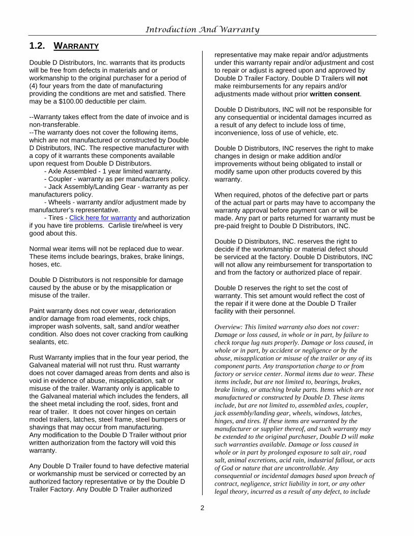
1.2. WARRANTY Double D Distributors, Inc. warrants that its products will be free from defects in materials and or workmanship to the original purchaser for a period of (4) four years from the date of manufacturing providing the conditions are met and satisfied. There may be a $100.00 deductible per claim. --Warranty takes effect from the date of invoice and is non-transferable. --The warranty does not cover the following items, which are not manufactured or constructed by Double D Distributors, INC. The respective manufacturer with a copy of it warrants these components available upon request from Double D Distributors. - Axle Assembled - 1 year limited warranty. - Coupler - warranty as per manufacturers policy. - Jack Assembly/Landing Gear - warranty as per manufacturers policy. - Wheels - warranty and/or adjustment made by manufacturer’s representative. - Tires - Click here for warranty and authorization if you have tire problems. Carlisle tire/wheel is very good about this. Normal wear items will not be replaced due to wear. These items include bearings, brakes, brake linings, hoses, etc. Double D Distributors is not responsible for damage caused by the abuse or by the misapplication or misuse of the trailer. Paint warranty does not cover wear, deterioration and/or damage from road elements, rock chips, improper wash solvents, salt, sand and/or weather condition. Also does not cover cracking from caulking sealants, etc. Rust Warranty implies that in the four year period, the Galvaneal material will not rust thru. Rust warranty does not cover damaged areas from dents and also is void in evidence of abuse, misapplication, salt or misuse of the trailer. Warranty only is applicable to the Galvaneal material which includes the fenders, all the sheet metal including the roof, sides, front and rear of trailer. It does not cover hinges on certain model trailers, latches, steel frame, steel bumpers or shavings that may occur from manufacturing. Any modification to the Double D Trailer without prior written authorization from the factory will void this warranty. Any Double D Trailer found to have defective material or workmanship must be serviced or corrected by an authorized factory representative or by the Double D Trailer Factory. Any Double D Trailer authorized
representative may make repair and/or adjustments under this warranty repair and/or adjustment and cost to repair or adjust is agreed upon and approved by Double D Trailer Factory. Double D Trailers will not make reimbursements for any repairs and/or adjustments made without prior written consent. Double D Distributors, INC will not be responsible for any consequential or incidental damages incurred as a result of any defect to include loss of time, inconvenience, loss of use of vehicle, etc. Double D Distributors, INC reserves the right to make changes in design or make addition and/or improvements without being obligated to install or modify same upon other products covered by this warranty. When required, photos of the defective part or parts of the actual part or parts may have to accompany the warranty approval before payment can or will be made. Any part or parts returned for warranty must be pre-paid freight to Double D Distributors, INC. Double D Distributors, INC. reserves the right to decide if the workmanship or material defect should be serviced at the factory. Double D Distributors, INC will not allow any reimbursement for transportation to and from the factory or authorized place of repair. Double D reserves the right to set the cost of warranty. This set amount would reflect the cost of the repair if it were done at the Double D Trailer facility with their personnel. Overview: This limited warranty also does not cover: Damage or loss caused, in whole or in part, by failure to check torque lug nuts properly. Damage or loss caused, in whole or in part, by accident or negligence or by the abuse, misapplication or misuse of the trailer or any of its component parts. Any transportation charge to or from factory or service center. Normal items due to wear. These items include, but are not limited to, bearings, brakes, brake lining, or attaching brake parts. Items which are not manufactured or constructed by Double D. These items include, but are not limited to, assembled axles, coupler, jack assembly/landing gear, wheels, windows, latches, hinges, and tires. If these items are warranted by the manufacturer or supplier thereof, and such warranty may be extended to the original purchaser, Double D will make such warranties available. Damage or loss caused in whole or in part by prolonged exposure to salt air, road salt, animal excretions, acid rain, industrial fallout, or acts of God or nature that are uncontrollable. Any consequential or incidental damages based upon breach of contract, negligence, strict liability in tort, or any other legal theory, incurred as a result of any defect, to include
Introduction And Warranty
3
loss of time, inconvenience, loss of use of vehicle, or any other fees incurred by purchaser relating to any warranty claim. THIS WARRANTY IS EXPRESSLY MADE IN LIEU OF ANY AND ALL OTHER WARRANTIES
EXPRESSED OR IMPLIED INCLUDING THE WARRANTIES OF MERCHANTABILITY AND FITNESS AND NO ONE IS AUTHORIZED TO MAKE ANY FURTHER OR ADDITIONAL WARRANTIES ON BEHALF OF Double D Distributors, INC.
4
2. SAFETY
2.1. SAFETY ALERT SYMBOLS AND SIGNAL WORDS
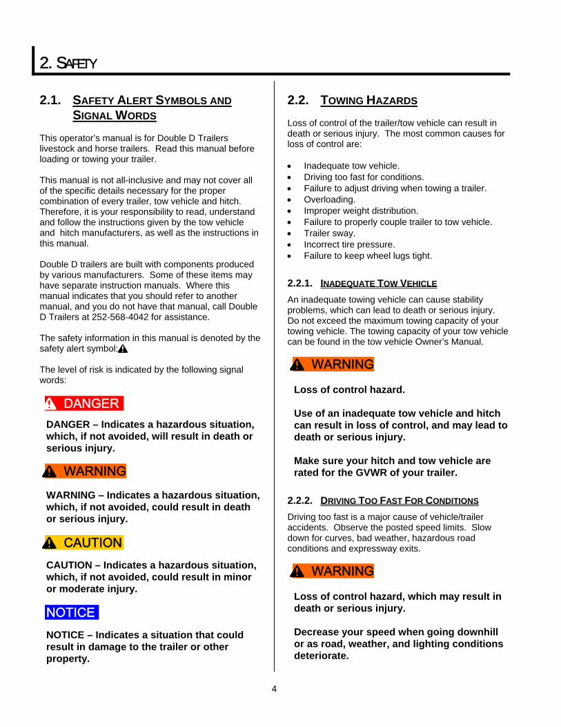
This operator’s manual is for Double D Trailers livestock and horse trailers. Read this manual before loading or towing your trailer. This manual is not all-inclusive and may not cover all of the specific details necessary for the proper combination of every trailer, tow vehicle and hitch. Therefore, it is your responsibility to read, understand and follow the instructions given by the tow vehicle and hitch manufacturers, as well as the instructions in this manual. Double D trailers are built with components produced by various manufacturers. Some of these items may have separate instruction manuals. Where this manual indicates that you should refer to another manual, and you do not have that manual, call Double D Trailers at 252-568-4042 for assistance. The safety information in this manual is denoted by the safety alert symbol: ^ The level of risk is indicated by the following signal words:
DANGER – Indicates a hazardous situation, which, if not avoided, will result in death or serious injury.
WARNING – Indicates a hazardous situation, which, if not avoided, could result in death or serious injury.
CAUTION – Indicates a hazardous situation, which, if not avoided, could result in minor or moderate injury.
NOTICE – Indicates a situation that could result in damage to the trailer or other property.
2.2. TOWING HAZARDS Loss of control of the trailer/tow vehicle can result in death or serious injury. The most common causes for loss of control are: • Inadequate tow vehicle. • Driving too fast for conditions. • Failure to adjust driving when towing a trailer. • Overloading. • Improper weight distribution. • Failure to properly couple trailer to tow vehicle. • Trailer sway. • Incorrect tire pressure. • Failure to keep wheel lugs tight.
2.2.1. INADEQUATE TOW VEHICLE An inadequate towing vehicle can cause stability problems, which can lead to death or serious injury. Do not exceed the maximum towing capacity of your towing vehicle. The towing capacity of your tow vehicle can be found in the tow vehicle Owner’s Manual.
Loss of control hazard. Use of an inadequate tow vehicle and hitch can result in loss of control, and may lead to death or serious injury. Make sure your hitch and tow vehicle are rated for the GVWR of your trailer.
2.2.2. DRIVING TOO FAST FOR CONDITIONS Driving too fast is a major cause of vehicle/trailer accidents. Observe the posted speed limits. Slow down for curves, bad weather, hazardous road conditions and expressway exits.
Loss of control hazard, which may result in death or serious injury. Decrease your speed when going downhill or as road, weather, and lighting conditions deteriorate.
^ DANGER
^ WARNING
^ CAUTION
NOTICE
^ WARNING
^ WARNING
Safety
5
2.2.3. CHANGED HANDLING WITH A TRAILER When towing a trailer, you will have: • Slower acceleration. • Increased stopping distance. • Increased turning radius. • Longer distance to pass, due the slower
acceleration. • Increased length. Also keep in mind the following:
• Beware of slippery road conditions. • Be alert for trailer sway due to excessive steering,
wind gusts, roadway edges, and passing trucks and busses. When encountering trailer sway: • Release accelerator, and move the steering
wheel as little as possible to stay on the road. Use small steering adjustments.
• Do not attempt to steer out of the sway, this can make the situation worse.
• Applying the trailer brakes alone will tend to straighten out the tow vehicle/trailer.
• Use rearview mirrors frequently to observe the trailer behavior and traffic behind you.
• Use lower a gear when going down steep or long grades. Do not ride the brakes or they may overheat to the point of becoming ineffective. Use the tow vehicle engine and transmission as a brake.
• Be aware of your trailer height.
2.2.4. TRAILER NOT PROPERLY COUPLED TO THE HITCH
A secure coupling is vital. Uncoupling can result in death or serious injury.
Risk of uncoupling, which may result in death or serious injury. Verify the hitch and ball are rated for the trailer. Verify the hitch ball size matches the trailer coupler size. Inspect the hitch for wear, corrosion and cracks before coupling. Replace worn or damaged parts before coupling the trailer to the tow vehicle.
Verify the hitch and ball are tight before coupling the trailer.
An improperly coupled trailer can result in death or serious injury. Before towing trailer, verify that:
• The coupler is properly secured and locked.
• Safety chains are secured to the tow vehicle or receivers designed for safety chains.
• Trailer jack is fully retracted. • Lights and breakaway switch are
connected and working properly. • Load is properly secured. • Brakes are functioning properly. • Perform pre-trip inspection.
2.2.5. CONNECTION OF SAFETY CHAINS Safety chains are provided so that control of the trailer can still be maintained if the trailer uncouples from the tow vehicle.
Improperly connected or failure to connect the safety chains can result in loss of control, leading to death or serious injury, if the trailer uncouples from the tow vehicle. Chains must:
• Fasten chains to frame or loops in the hitch specifically for that purpose.
• Cross underneath hitch and coupler. 2.2.6. CONNECTION OF BREAKAWAY BRAKE If equipped with brakes, your trailer is equipped with a breakaway brake system that can apply the brakes on your trailer if your trailer comes loose from the for any reason.
^ WARNING
^ WARNING
^ WARNING
Safety
6
An improperly connected or inoperative breakaway brake system can result in a runaway trailer, if the coupler or hitch fails, leading to death or serious injury. Connect the breakaway lanyard to the tow vehicle and not to any part of the hitch, safety chain, ball or support. Test the function of the breakaway brake system before each tow. If the breakaway brake system is not working, do not tow the trailer; have it repaired.
2.2.7. MISMATCH BETWEEN TRAILER AND HITCH
Loss of control hazard. Use of an under rated hitch, ball or tow vehicle may result in loss of control leading to death or serious injury. Make certain your tow vehicle and hitch are rated for your trailer.
2.2.8. INSPECT TIRES, WHEELS AND LUG NUTS Inspect the trailer tires and wheels, and tighten lug nuts before each tow. If a tire has a bald spot, bulge, cut, cracks or is showing any cords, replace tire before towing. If a tire has uneven tread wear, take the trailer to a trailer service center for diagnosis. Tires with too little tread will not provide adequate traction and can result in loss of control, leading to death or serious injury. Improper tire pressure causes increased tire wear and an unstable trailer, which can result in a tire blowout or possible loss of control. The tire pressure is listed on the VIN label. Allow 3 hours cool-down after driving as much as 1 mile at 40 mph before checking tire pressure.
Improper tire pressure can cause an unstable trailer. Tire blowout and loss of control may occur. Death or serious injury may result. Inflate tires to pressure indicated on the Certification / VIN label before towing trailer.
Trailer wheels and lugs are subjected to greater side loads than automobile wheels. This may cause the wheel lugs to become loose. The wheel lugs must be tight to keep the wheels properly seated to the hub. Before each tow, check to make sure they are tight.
The proper tightness (torque) and tightening sequence for lug nuts is listed in the maintenance section of this manual. Use a torque wrench to tighten the lug nuts and use the crisscross star pattern. Lug nuts are also prone to loosen after first being assembled or remounted. When towing a new trailer (or after wheels have been remounted), check to make sure they are tight after the first 10, 25 and 50 miles of driving and before each tow thereafter. Failure to perform this check can result in a wheel separating from the trailer and a collision, leading to death or serious injury.
Improper wheel lug nut torque can cause a wheel to part from the trailer while towing, leading to death or serious injury. Check wheel lug nuts for tightness on a new trailer or when wheel(s) have been remounted after the first 10, 25 and 50 miles of driving and before each tow thereafter.
2.2.9. OVERLOADING An overloaded trailer can result in loss of control, which may result in death or serious injury. Overloading and improper loading may also result in tire, wheel, axle or structural failure, and also increased stopping distances. If your trailer is equipped with a Tire & Loading Information Placard, the cargo capacity weight stated on that placard is a close estimate. The GVWR is listed on the Certification / VIN label.
^ WARNING
^ DANGER
^ WARNING
^ WARNING
Safety
7
An overloaded trailer can result failure or loss of control of the trailer, leading to death or serious injury. Never load a trailer so that the weight on any tire exceeds its rating. Never exceed the trailer Gross Vehicle Weight Rating (GVWR). Never exceed an axle Gross Axle Weight Rating (GAWR).
2.2.10. IMPROPER LOAD DISTRIBUTION Improper load distribution can result in poor trailer stability and handling. Uneven load distribution can cause tire, wheel, axle or structural failure. Proper weight distribution is equal left-to-right and proper tongue weight for stable trailer handling. The rule of thumb for proper tongue weight on a tagalong trailer is 10-15% of GVW or 20-25% of GVW on a gooseneck trailer. Keep the center of gravity as low as possible. After loading, be sure to check that none of the axles are overloaded.
Collision and/or tip over hazard. An improperly loaded trailer can result in failure or loss of control, leading to death or serious injury. Distribute the load front-to-rear to provide proper tongue weight. Distribute the load evenly, right and left and also throughout the trailer. Keeping the center of gravity low and centered is essential to minimize the risk of tipping over.
2.2.11. SHIFTING CARGO You are responsible for securing the cargo so it does not shift in the trailer while towing. Be certain doors
are properly latched to prevent the doors from opening while towing. Use a linchpin to prevent the door latch from opening.
Shifting cargo can result in failure or loss of control of the trailer, and can lead to death or serious injury. Secure loads with proper sized fasteners, ropes, straps, etc. Install lynch pin to prevent doors from opening while towing.
2.2.12. INAPPROPRIATE CARGO If your trailer is designed for specific cargo, only carry that cargo in the trailer. A trailer must not be used to carry certain items, such as people, containers of hazardous or flammable substances.
Do not transport people in the trailer. The transport of people puts their lives at risk and is illegal.
Do not transport flammable, explosive, poisonous or other dangerous materials in your trailer. Exceptions:
• Fuel in the tanks of vehicles or equipment that are being hauled.
• Fuel stored in proper containers used in trailer living quarters for cooking.
• Fuel stored in the tank of an installed generator.
2.2.13. BRAKES, LIGHTS OR MIRRORS The brakes and lights are controlled via a connection to the tow vehicle by a multi-pin connector. Trailer brakes are essential for slowing the trailer. Lights are essential for drivers behind you to see you at night and be alerted of your intended moves. Before towing the trailer, make sure the brakes and all lights on your trailer are functioning properly.
^ WARNING
^ WARNING
^ WARNING
^ WARNING
^ WARNING
Safety
8
Failure to connect the tow vehicle lighting and braking the trailer will result in inoperable lights and brakes, and may lead to collision. Before towing, check that all lights and brakes work.
You must provide mirrors that allow you to safely observe and maneuver in traffic.
2.2.14. HAZARDS FROM MODIFYING YOUR TRAILER Altering or modifying your trailer can damage safety and structural items and may void the warranty. Before making any alteration to your trailer, contact your dealer or Double D Trailers at 252-568-4042 and describe the alteration you are contemplating. Alteration of the trailer must be performed only by qualified technicians who are familiar with your trailer and with the approval of Double D Trailers.
2.2.15. HAZARDS TO HORSES You must be aware of a horse’s temperament before attempting to haul it. Your Double D horse trailer is designed to safely contain your horse. Restrain the horse using a combination of a tie-strap and stall divider. Before loading your horse, inspect the interior of the trailer to insure that there are no hazards inside the trailer.
A frightened horse is capable of inflicting serious injury or death to a human handler. Know your horse’s temperament before attempting to haul it. Handling a horse that is not trailer-acclimated may result in injury or death. Do not haul an unbroken horse in this trailer. Horses must have a halter.
Failure to secure a horse using a tie strap may result in its serious injury or death.
The trailer interior may have hazards that can result in serious injury or death to a horse. Before loading a horse, inspect the trailer interior and adjust or repair all loose and protruding features. Before towing: • Close and lock all stall dividers. • Be sure all saddles, tack, equipment
and horse(s) are secured.
Hauling a horse in a livestock trailer may result in its death or serious injury. Use a trailer designed to carry horses.
2.2.16. HAZARDS TO LIVESTOCK Your Double D livestock trailer is designed to haul livestock. It is not designed or equipped for hauling horses. Before loading your livestock, inspect the interior of the trailer to insure that there are no hazards inside the trailer.
Livestock are capable of inflicting serious injury or death to a human handler. Know your animals’ temperament before attempting to haul them.
2.2.17. HAZARDS FROM ACCESSORIES The “Accessories” section of this manual contains information about optional accessories that may be on your trailer.
^ WARNING
^ WARNING
^ WARNING
^ WARNING
^ WARNING
Safety
9
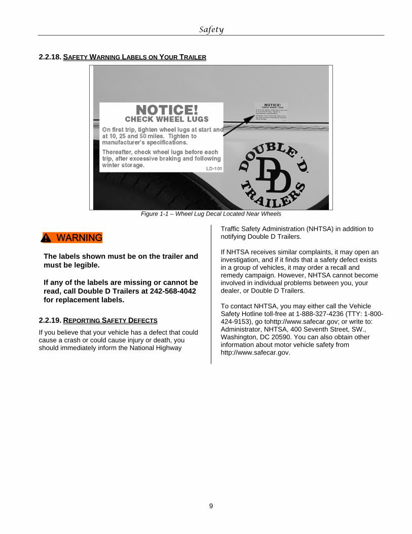
2.2.18. SAFETY WARNING LABELS ON YOUR TRAILER
Figure 1-1 – Wheel Lug Decal Located Near Wheels
The labels shown must be on the trailer and must be legible. If any of the labels are missing or cannot be read, call Double D Trailers at 242-568-4042 for replacement labels.
2.2.19. REPORTING SAFETY DEFECTS If you believe that your vehicle has a defect that could cause a crash or could cause injury or death, you should immediately inform the National Highway
Traffic Safety Administration (NHTSA) in addition to notifying Double D Trailers. If NHTSA receives similar complaints, it may open an investigation, and if it finds that a safety defect exists in a group of vehicles, it may order a recall and remedy campaign. However, NHTSA cannot become involved in individual problems between you, your dealer, or Double D Trailers. To contact NHTSA, you may either call the Vehicle Safety Hotline toll-free at 1-888-327-4236 (TTY: 1-800-424-9153), go tohttp://www.safecar.gov; or write to: Administrator, NHTSA, 400 Seventh Street, SW., Washington, DC 20590. You can also obtain other information about motor vehicle safety from http://www.safecar.gov.
^ WARNING
10
3. TIRE SAFETY INFORMATION This portion of the Owner’s Manual contains tire safety information as required by 49 CFR 575.6. Section 3.1 contains “Steps for Determining Correct Load Limit - Trailer”. Section 3.2 contains a Glossary of Tire Terminology, including “cold inflation pressure”, “maximum inflation pressure”, “recommended inflation pressure”, and other non-technical terms. Section 3.3 contains information from the NHTSA brochure entitled “Tire Safety – Everything Rides On It”.
3.1. STEPS FOR DETERMINING CORRECT LOAD LIMIT – TRAILER
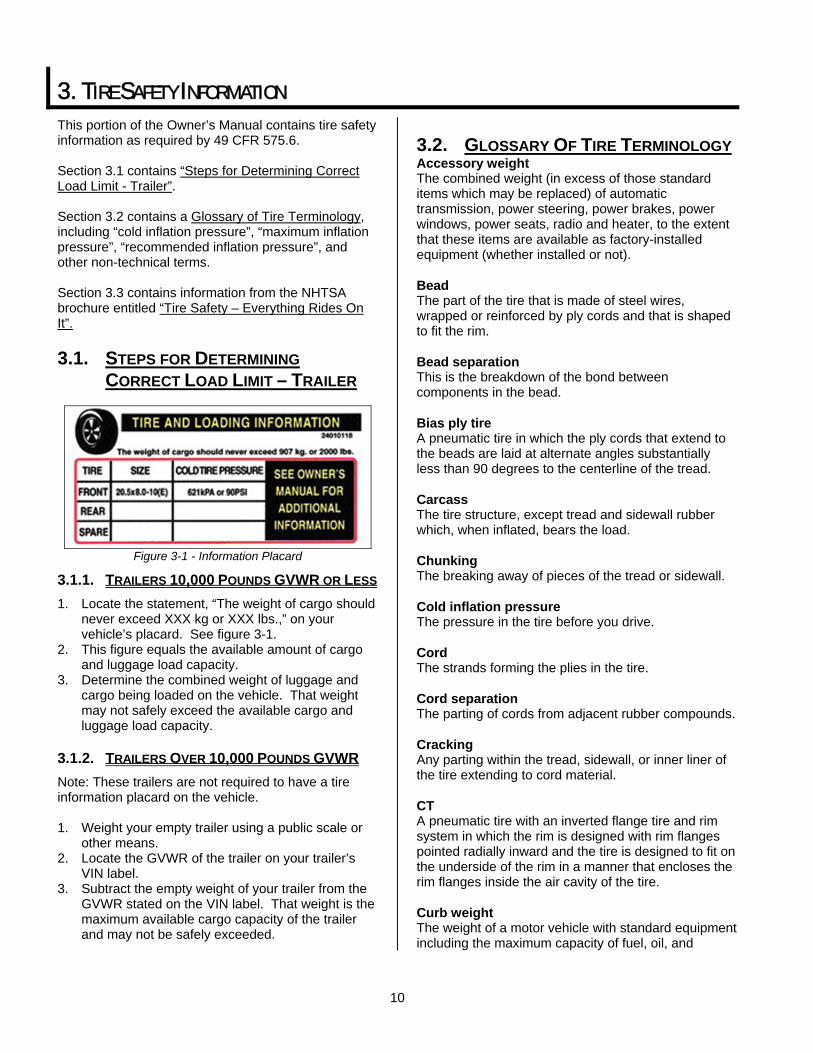
Figure 3-1 - Information Placard
3.1.1. TRAILERS 10,000 POUNDS GVWR OR LESS 1. Locate the statement, “The weight of cargo should
never exceed XXX kg or XXX lbs.,” on your vehicle’s placard. See figure 3-1.
2. This figure equals the available amount of cargo and luggage load capacity.
3. Determine the combined weight of luggage and cargo being loaded on the vehicle. That weight may not safely exceed the available cargo and luggage load capacity.
3.1.2. TRAILERS OVER 10,000 POUNDS GVWR Note: These trailers are not required to have a tire information placard on the vehicle. 1. Weight your empty trailer using a public scale or
other means. 2. Locate the GVWR of the trailer on your trailer’s
VIN label. 3. Subtract the empty weight of your trailer from the
GVWR stated on the VIN label. That weight is the maximum available cargo capacity of the trailer and may not be safely exceeded.
3.2. GLOSSARY OF TIRE TERMINOLOGY Accessory weight The combined weight (in excess of those standard items which may be replaced) of automatic transmission, power steering, power brakes, power windows, power seats, radio and heater, to the extent that these items are available as factory-installed equipment (whether installed or not). Bead The part of the tire that is made of steel wires, wrapped or reinforced by ply cords and that is shaped to fit the rim. Bead separation This is the breakdown of the bond between components in the bead. Bias ply tire A pneumatic tire in which the ply cords that extend to the beads are laid at alternate angles substantially less than 90 degrees to the centerline of the tread. Carcass The tire structure, except tread and sidewall rubber which, when inflated, bears the load. Chunking The breaking away of pieces of the tread or sidewall. Cold inflation pressure The pressure in the tire before you drive. Cord The strands forming the plies in the tire. Cord separation The parting of cords from adjacent rubber compounds. Cracking Any parting within the tread, sidewall, or inner liner of the tire extending to cord material. CT A pneumatic tire with an inverted flange tire and rim system in which the rim is designed with rim flanges pointed radially inward and the tire is designed to fit on the underside of the rim in a manner that encloses the rim flanges inside the air cavity of the tire. Curb weight The weight of a motor vehicle with standard equipment including the maximum capacity of fuel, oil, and
Tire Safety Information
11
coolant, and, if so equipped, air conditioning and additional weight optional engine. Extra load tire A tire designed to operate at higher loads and at higher inflation pressures than the corresponding standard tire. Groove The space between two adjacent tread ribs. Innerliner The layer(s) forming the inside surface of a tubeless tire that contains the inflating medium within the tire. Innerliner separation The parting of the innerliner from cord material in the carcass. Intended outboard sidewall The sidewall that contains a white-wall, bears white lettering or bears manufacturer, brand, and/or model name molding that is higher or deeper than the same molding on the other sidewall of the tire or the outward facing sidewall of an asymmetrical tire that has a particular side that must always face outward when mounted on a vehicle. Light truck (LT) tire A tire designated by its manufacturer as primarily intended for use on lightweight trucks or multipurpose passenger vehicles. Load rating The maximum load that a tire is rated to carry for a given inflation pressure. Maximum load rating The load rating for a tire at the maximum permissible inflation pressure for that tire. Maximum permissible inflation pressure The maximum cold inflation pressure to which a tire may be inflated. Maximum loaded vehicle weight The sum of curb weight, accessory weight, vehicle capacity weight, and production options weight. Measuring rim The rim on which a tire is fitted for physical dimension requirements. Non-pneumatic rim A mechanical device which, when a non-pneumatic tire assembly incorporates a wheel, supports the tire, and attaches, either integrally or separably, to the
wheel center member and upon which the tire is attached. Non-pneumatic spare tire assembly A non-pneumatic tire assembly intended for temporary use in place of one of the pneumatic tires and rims that are fitted to a passenger car in compliance with the requirements of this standard. Non-pneumatic tire A mechanical device which transmits, either directly or through a wheel or wheel center member, the vertical load and tractive forces from the roadway to the vehicle, generates the tractive forces that provide the directional control of the vehicle and does not rely on the containment of any gas or fluid for providing those functions. Non-pneumatic tire assembly A non-pneumatic tire, alone or in combination with a wheel or wheel center member, which can be mounted on a vehicle. Normal occupant weight This means 68 kilograms (150 lbs.) times the number of occupants specified in the second column of Table I of 49 CFR 571.110. Occupant distribution The distribution of occupants in a vehicle as specified in the third column of Table I of 49 CFR 571.110. Open splice Any parting at any junction of tread, sidewall, or innerliner that extends to cord material. Outer diameter The overall diameter of an inflated new tire. Overall width The linear distance between the exteriors of the sidewalls of an inflated tire, including elevations due to labeling, decorations, or protective bands or ribs. Ply A layer of rubber-coated parallel cords. Ply separation A parting of rubber compound between adjacent plies. Pneumatic tire A mechanical device made of rubber, chemicals, fabric and steel or other materials, that, when mounted on an automotive wheel, provides the traction and contains the gas or fluid that sustains the load.
Tire Safety Information
12
Production options weight The combined weight of those installed regular production options weighing over 2.3 kilograms (5 lbs.) in excess of those standard items which they replace, not previously considered in curb weight or accessory weight, including heavy duty brakes, ride levelers, roof rack, heavy duty battery, and special trim. Radial ply tire A pneumatic tire in which the ply cords that extend to the beads are laid at substantially 90 degrees to the centerline of the tread. Recommended inflation pressure This is the inflation pressure provided by the vehicle manufacturer on the Tire Information label and on the Certification / VIN tag. Reinforced tire A tire designed to operate at higher loads and at higher inflation pressures than the corresponding standard tire. Rim A metal support for a tire or a tire and tube assembly upon which the tire beads are seated. Rim diameter This means the nominal diameter of the bead seat. Rim size designation This means the rim diameter and width. Rim type designation This means the industry of manufacturer’s designation for a rim by style or code. Rim width This means the nominal distance between rim flanges. Section width The linear distance between the exteriors of the sidewalls of an inflated tire, excluding elevations due to labeling, decoration, or protective bands. Sidewall That portion of a tire between the tread and bead. Sidewall separation The parting of the rubber compound from the cord material in the sidewall. Special Trailer (ST) tire The "ST" is an indication the tire is for trailer use only. Test rim The rim on which a tire is fitted for testing, and may be any rim listed as appropriate for use with that tire.
Tread That portion of a tire that comes into contact with the road. Tread rib A tread section running circumferentially around a tire. Tread separation Pulling away of the tread from the tire carcass. Treadwear indicators (TWI) The projections within the principal grooves designed to give a visual indication of the degrees of wear of the tread. Vehicle capacity weight The rated cargo and luggage load plus 68 kilograms (150 lbs.) times the vehicle’s designated seating capacity. Vehicle maximum load on the tire The load on an individual tire that is determined by distributing to each axle its share of the maximum loaded vehicle weight and dividing by two. Vehicle normal load on the tire The load on an individual tire that is determined by distributing to each axle its share of the curb weight, accessory weight, and normal occupant weight (distributed in accordance with Table I of CRF 49 571.110) and dividing by 2. Weather side The surface area of the rim not covered by the inflated tire. Wheel center member In the case of a non-pneumatic tire assembly incorporating a wheel, a mechanical device which attaches, either integrally or separably, to the non-pneumatic rim and provides the connection between the non-pneumatic rim and the vehicle; or, in the case of a non-pneumatic tire assembly not incorporating a wheel, a mechanical device which attaches, either integrally or separably, to the non-pneumatic tire and provides the connection between tire and the vehicle. Wheel-holding fixture The fixture used to hold the wheel and tire assembly securely during testing.
3.3. TIRE SAFETY - EVERYTHING RIDES ON IT
The National Traffic Safety Administration (NHTSA) has published a brochure (DOT HS 809 361) that discusses all aspects of Tire Safety, as required by
Tire Safety Information
13
CFR 575.6. This brochure is reproduced in part below. It can be obtained and downloaded from NHTSA, free of charge, from the following web site: http://www.nhtsa.dot.gov/cars/rules/TireSafety/ridesonit/tires_index.html Studies of tire safety show that maintaining proper tire pressure, observing tire and vehicle load limits (not carrying more weight in your vehicle than your tires or vehicle can safely handle), avoiding road hazards, and inspecting tires for cuts, slashes, and other irregularities are the most important things you can do to avoid tire failure, such as tread separation or blowout and flat tires. These actions, along with other care and maintenance activities, can also: • Improve vehicle handling • Help protect you and others from avoidable
breakdowns and accidents • Improve fuel economy • Increase the life of your tires. This booklet presents a comprehensive overview of tire safety, including information on the following topics: • Basic tire maintenance • Uniform Tire Quality Grading System • Fundamental characteristics of tires • Tire safety tips. Use this information to make tire safety a regular part of your vehicle maintenance routine. Recognize that the time you spend is minimal compared with the inconvenience and safety consequences of a flat tire or other tire failure.
3.3.1. SAFETY FIRST–BASIC TIRE MAINTENANCE Properly maintained tires improve the steering, stopping, traction, and load-carrying capability of your vehicle. Underinflated tires and overloaded vehicles are a major cause of tire failure. Therefore, as mentioned above, to avoid flat tires and other types of tire failure, you should maintain proper tire pressure, observe tire and vehicle load limits, avoid road hazards, and regularly inspect your tires.
3.3.2. FINDING YOUR VEHICLE'S RECOMMENDED TIRE PRESSURE AND LOAD LIMITS
Tire information placards and vehicle certification labels contain information on tires and load limits. These labels indicate the vehicle manufacturer's information including: • Recommended tire size • Recommended tire inflation pressure
• Vehicle capacity weight (VCW–the maximum occupant and cargo weight a vehicle is designed to carry)
• Front and rear gross axle weight ratings (GAWR– the maximum weight the axle systems are designed to carry).
Both placards and certification labels are permanently attached to the trailer near the left front.
3.3.3. UNDERSTANDING TIRE PRESSURE AND LOAD LIMITS
Tire inflation pressure is the level of air in the tire that provides it with load-carrying capacity and affects the overall performance of the vehicle. The tire inflation pressure is a number that indicates the amount of air pressure– measured in pounds per square inch (psi)–a tire requires to be properly inflated. (You will also find this number on the vehicle information placard expressed in kilopascals (kPa), which is the metric measure used internationally.) Manufacturers of passenger vehicles and light trucks determine this number based on the vehicle's design load limit, that is, the greatest amount of weight a vehicle can safely carry and the vehicle's tire size. The proper tire pressure for your vehicle is referred to as the "recommended cold inflation pressure." (As you will read below, it is difficult to obtain the recommended tire pressure if your tires are not cold.) Because tires are designed to be used on more than one type of vehicle, tire manufacturers list the "maximum permissible inflation pressure" on the tire sidewall. This number is the greatest amount of air pressure that should ever be put in the tire under normal driving conditions.
3.3.4. CHECKING TIRE PRESSURE It is important to check your vehicle's tire pressure at least once a month for the following reasons:
• Most tires may naturally lose air over time. • Tires can lose air suddenly if you drive over a
pothole or other object or if you strike the curb when parking.
• With radial tires, it is usually not possible to determine underinflation by visual inspection.
For convenience, purchase a tire pressure gauge to keep in your vehicle. Gauges can be purchased at tire dealerships, auto supply stores, and other retail outlets. The recommended tire inflation pressure that vehicle manufacturers provide reflects the proper psi when a tire is cold. The term cold does not relate to the outside temperature. Rather, a cold tire is one that has not been driven on for at least three hours. When you drive, your tires get warmer, causing the air pressure
Tire Safety Information
14
within them to increase. Therefore, to get an accurate tire pressure reading, you must measure tire pressure when the tires are cold or compensate for the extra pressure in warm tires.
3.3.5. STEPS FOR MAINTAINING PROPER TIRE PRESSURE
• Step 1: Locate the recommended tire pressure on the vehicle's tire sidewall or in the owner's manual.
• Step 2: Record the tire pressure of all tires. • Step 3: If the tire pressure is too high in any of
the tires, slowly release air by gently pressing on the tire valve stem with the edge of your tire gauge until you get to the correct pressure.
• Step 4: If the tire pressure is too low, note the difference between the measured tire pressure and the correct tire pressure. These "missing" pounds of pressure are what you will need to add.
• Step 5: At a service station, add the missing pounds of air pressure to each tire that is underinflated.
• Step 6: Check all the tires to make sure they have the same air pressure (except in cases in which the front and rear tires are supposed to have different amounts of pressure).
If you have been driving your vehicle and think that a tire is underinflated, fill it to the recommended cold inflation pressure indicated on your vehicle's tire information placard or certification label. While your tire may still be slightly underinflated due to the extra pounds of pressure in the warm tire, it is safer to drive with air pressure that is slightly lower than the vehicle manufacturer's recommended cold inflation pressure than to drive with a significantly underinflated tire. Since this is a temporary fix, don't forget to recheck and adjust the tire's pressure when you can obtain a cold reading.
3.3.6. TIRE SIZE To maintain tire safety, purchase new tires that are the same size as the vehicle's original tires or another size recommended by the manufacturer. Look at the tire information placard, the owner's manual, or the sidewall of the tire you are replacing to find this information. If you have any doubt about the correct size to choose, consult with the tire dealer.
3.3.7. TIRE TREAD The tire tread provides the gripping action and traction that prevent your vehicle from slipping or sliding, especially when the road is wet or icy. In general, tires are not safe and should be replaced when the tread is worn down to 1/16 of an inch. Tires have built-in
treadwear indicators that let you know when it is time to replace your tires. These indicators are raised sections spaced intermittently in the bottom of the tread grooves. When they appear "even" with the outside of the tread, it is time to replace your tires. Another method for checking tread depth is to place a penny in the tread with Lincoln's head upside down and facing you. If you can see the top of Lincoln's head, you are ready for new tires.
3.3.8. TIRE BALANCE AND WHEEL ALIGNMENT To avoid vibration or shaking of the vehicle when a tire rotates, the tire must be properly balanced. This balance is achieved by positioning weights on the wheel to counterbalance heavy spots on the wheel-and-tire assembly. A wheel alignment adjusts the angles of the wheels so that they are positioned correctly relative to the vehicle's frame. This adjustment maximizes the life of your tires. These adjustments require special equipment and should be performed by a qualified technician.
3.3.9. TIRE REPAIR The proper repair of a punctured tire requires a plug for the hole and a patch for the area inside the tire that surrounds the puncture hole. Punctures through the tread can be repaired if they are not too large, but punctures to the sidewall should not be repaired. Tires must be removed from the rim to be properly inspected before being plugged and patched.
3.3.10. TIRE FUNDAMENTALS Federal law requires tire manufacturers to place standardized information on the sidewall of all tires. This information identifies and describes the fundamental characteristics of the tire and also provides a tire identification number for safety standard certification and in case of a recall.
Tire Safety Information
15
3.3.10.1. Information on Passenger Vehicle Tires
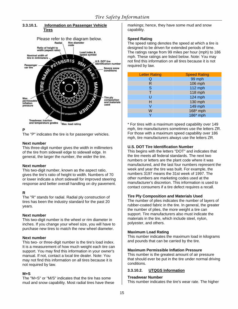
Please refer to the diagram below.
P The "P" indicates the tire is for passenger vehicles. Next number This three-digit number gives the width in millimeters of the tire from sidewall edge to sidewall edge. In general, the larger the number, the wider the tire. Next number This two-digit number, known as the aspect ratio, gives the tire's ratio of height to width. Numbers of 70 or lower indicate a short sidewall for improved steering response and better overall handling on dry pavement. R The "R" stands for radial. Radial ply construction of tires has been the industry standard for the past 20 years. Next number This two-digit number is the wheel or rim diameter in inches. If you change your wheel size, you will have to purchase new tires to match the new wheel diameter. Next number This two- or three-digit number is the tire's load index. It is a measurement of how much weight each tire can support. You may find this information in your owner's manual. If not, contact a local tire dealer. Note: You may not find this information on all tires because it is not required by law. M+S The "M+S" or "M/S" indicates that the tire has some mud and snow capability. Most radial tires have these
markings; hence, they have some mud and snow capability. Speed Rating The speed rating denotes the speed at which a tire is designed to be driven for extended periods of time. The ratings range from 99 miles per hour (mph) to 186 mph. These ratings are listed below. Note: You may not find this information on all tires because it is not required by law.
Letter Rating Speed Rating Q 99 mph R 106 mph S 112 mph T 118 mph U 124 mph H 130 mph V 149 mph W 168* mph Y 186* mph
* For tires with a maximum speed capability over 149 mph, tire manufacturers sometimes use the letters ZR. For those with a maximum speed capability over 186 mph, tire manufacturers always use the letters ZR. U.S. DOT Tire Identification Number This begins with the letters "DOT" and indicates that the tire meets all federal standards. The next two numbers or letters are the plant code where it was manufactured, and the last four numbers represent the week and year the tire was built. For example, the numbers 3197 means the 31st week of 1997. The other numbers are marketing codes used at the manufacturer's discretion. This information is used to contact consumers if a tire defect requires a recall. Tire Ply Composition and Materials Used The number of plies indicates the number of layers of rubber-coated fabric in the tire. In general, the greater the number of plies, the more weight a tire can support. Tire manufacturers also must indicate the materials in the tire, which include steel, nylon, polyester, and others. Maximum Load Rating This number indicates the maximum load in kilograms and pounds that can be carried by the tire. Maximum Permissible Inflation Pressure This number is the greatest amount of air pressure that should ever be put in the tire under normal driving conditions.
3.3.10.2. UTQGS Information
Treadwear Number This number indicates the tire's wear rate. The higher
Tire Safety Information
16
the treadwear number is, the longer it should take for the tread to wear down. For example, a tire graded 400 should last twice as long as a tire graded 200. Traction Letter This letter indicates a tire's ability to stop on wet pavement. A higher graded tire should allow you to stop your car on wet roads in a shorter distance than a tire with a lower grade. Traction is graded from highest to lowest as "AA","A", "B", and "C". Temperature Letter This letter indicates a tire's resistance to heat. The temperature grade is for a tire that is inflated properly and not overloaded. Excessive speed, underinflation or excessive loading, either separately or in combination, can cause heat build-up and possible tire failure. From highest to lowest, a tire's resistance to heat is graded as "A", "B", or "C".
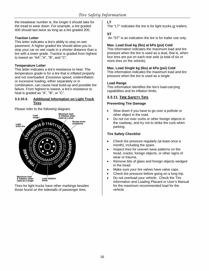
3.3.10.3. Additional Information on Light Truck Tires
Please refer to the following diagram.
Tires for light trucks have other markings besides those found on the sidewalls of passenger tires.
LT The "LT" indicates the tire is for light trucks or trailers. ST An "ST" is an indication the tire is for trailer use only. Max. Load Dual kg (lbs) at kPa (psi) Cold This information indicates the maximum load and tire pressure when the tire is used as a dual, that is, when four tires are put on each rear axle (a total of six or more tires on the vehicle). Max. Load Single kg (lbs) at kPa (psi) Cold This information indicates the maximum load and tire pressure when the tire is used as a single. Load Range This information identifies the tire's load-carrying capabilities and its inflation limits.
3.3.11. TIRE SAFETY TIPS Preventing Tire Damage • Slow down if you have to go over a pothole or
other object in the road. • Do not run over curbs or other foreign objects in
the roadway, and try not to strike the curb when parking.
Tire Safety Checklist • Check tire pressure regularly (at least once a
month), including the spare. • Inspect tires for uneven wear patterns on the
tread, cracks, foreign objects, or other signs of wear or trauma.
• Remove bits of glass and foreign objects wedged in the tread.
• Make sure your tire valves have valve caps. • Check tire pressure before going on a long trip. • Do not overload your vehicle. Check the Tire
Information and Loading Placard or User’s Manual for the maximum recommended load for the vehicle.
17
4. COUPLE TO TOW VEHICLE
4.1. USE AN ADEQUATE TOW VEHICLE AND HITCH
The vehicle and hitch must be matched to the Gross Vehicle Weight Rating (GVWR) of your trailer or you can cause an accident that could lead to death or serious injury.
Use of an under rated hitch and/or tow vehicle can result in loss of control and may lead to death or serious injury.
Verify that your hitch and tow vehicle are rated for the Gross Vehicle Weight Rating of your trailer.
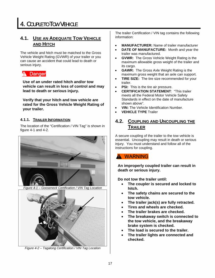
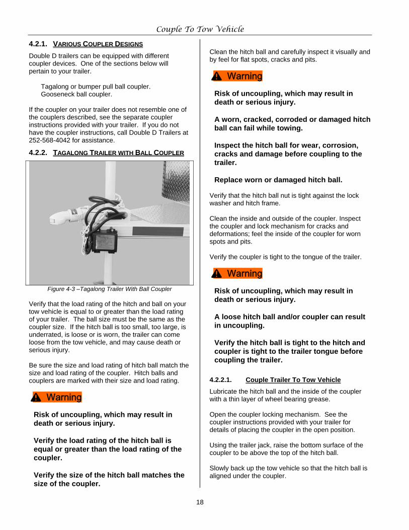
4.1.1. TRAILER INFORMATION The location of the “Certification / VIN Tag” is shown in figure 4-1 and 4-2.
Figure 4-1 – Gooseneck Certification / VIN Tag Location
Figure 4-2 – Tagalong Certification / VIN Tag Location
The trailer Certification / VIN tag contains the following information: • MANUFACTURER: Name of trailer manufacturer • DATE OF MANUFACTURE: Month and year the
trailer was manufactured. • GVWR: The Gross Vehicle Weight Rating is the
maximum allowable gross weight of the trailer and its cargo.
• GAWR: The Gross Axle Weight Rating is the maximum gross weight that an axle can support.
• TIRE SIZE: The tire size recommended for your trailer.
• PSI: This is the tire air pressure. • CERTIFICATION STATEMENT: “This trailer
meets all the Federal Motor Vehicle Safety Standards in effect on the date of manufacture shown above”.
• VIN: The Vehicle Identification Number. • VEHICLE TYPE Trailer
4.2. COUPLING AND UNCOUPLING THE TRAILER
A secure coupling of the trailer to the tow vehicle is essential. Uncoupling may result in death or serious injury. You must understand and follow all of the instructions for coupling.
An improperly coupled trailer can result in death or serious injury. Do not tow the trailer until: • The coupler is secured and locked to
hitch. • The safety chains are secured to the
tow vehicle. • The trailer jack(s) are fully retracted. • Tires and wheels are checked. • The trailer brakes are checked. • The breakaway switch is connected to
the tow vehicle, and the breakaway brake system is checked.
• The load is secured to the trailer. • The trailer lights are connected and
checked.
^ Danger
^ WARNING
Couple To Tow Vehicle
18
4.2.1. VARIOUS COUPLER DESIGNS Double D trailers can be equipped with different coupler devices. One of the sections below will pertain to your trailer.
Tagalong or bumper pull ball coupler. Gooseneck ball coupler.
If the coupler on your trailer does not resemble one of the couplers described, see the separate coupler instructions provided with your trailer. If you do not have the coupler instructions, call Double D Trailers at 252-568-4042 for assistance.
4.2.2. TAGALONG TRAILER WITH BALL COUPLER
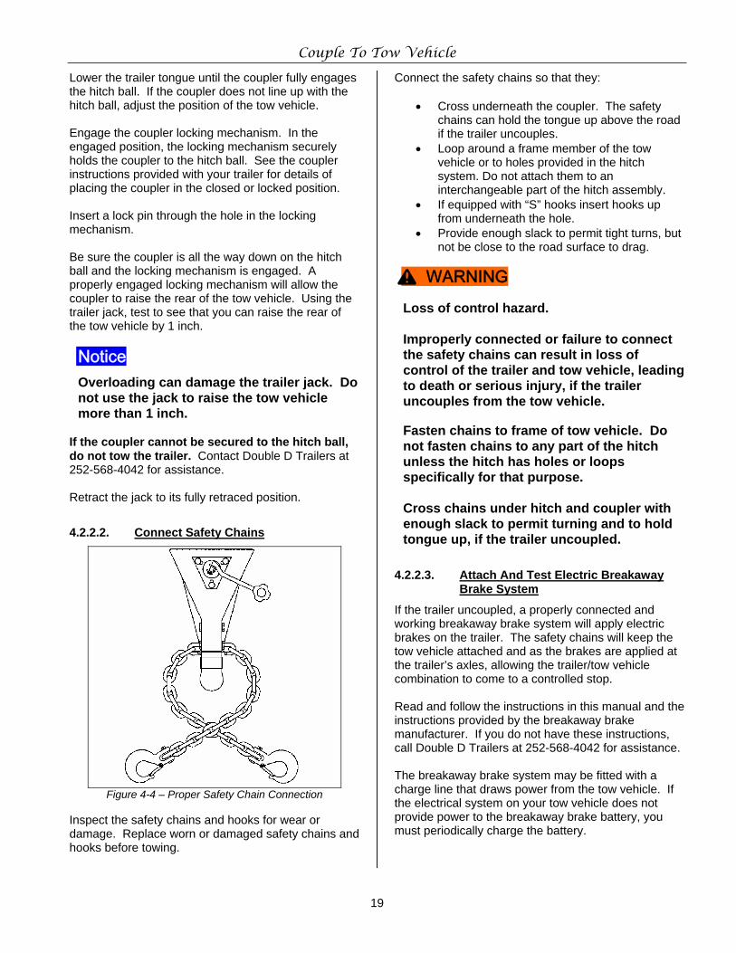
Figure 4-3 –Tagalong Trailer With Ball Coupler Verify that the load rating of the hitch and ball on your tow vehicle is equal to or greater than the load rating of your trailer. The ball size must be the same as the coupler size. If the hitch ball is too small, too large, is underrated, is loose or is worn, the trailer can come loose from the tow vehicle, and may cause death or serious injury. Be sure the size and load rating of hitch ball match the size and load rating of the coupler. Hitch balls and couplers are marked with their size and load rating.
Risk of uncoupling, which may result in death or serious injury.
Verify the load rating of the hitch ball is equal or greater than the load rating of the coupler. Verify the size of the hitch ball matches the size of the coupler.
Clean the hitch ball and carefully inspect it visually and by feel for flat spots, cracks and pits.
Risk of uncoupling, which may result in death or serious injury. A worn, cracked, corroded or damaged hitch ball can fail while towing. Inspect the hitch ball for wear, corrosion, cracks and damage before coupling to the trailer. Replace worn or damaged hitch ball.
Verify that the hitch ball nut is tight against the lock washer and hitch frame. Clean the inside and outside of the coupler. Inspect the coupler and lock mechanism for cracks and deformations; feel the inside of the coupler for worn spots and pits.
Verify the coupler is tight to the tongue of the trailer.
Risk of uncoupling, which may result in death or serious injury. A loose hitch ball and/or coupler can result in uncoupling. Verify the hitch ball is tight to the hitch and coupler is tight to the trailer tongue before coupling the trailer.
4.2.2.1. Couple Trailer To Tow Vehicle
Lubricate the hitch ball and the inside of the coupler with a thin layer of wheel bearing grease. Open the coupler locking mechanism. See the coupler instructions provided with your trailer for details of placing the coupler in the open position. Using the trailer jack, raise the bottom surface of the coupler to be above the top of the hitch ball. Slowly back up the tow vehicle so that the hitch ball is aligned under the coupler.
^ Warning
^ Warning
^ Warning
Couple To Tow Vehicle
19
Lower the trailer tongue until the coupler fully engages the hitch ball. If the coupler does not line up with the hitch ball, adjust the position of the tow vehicle. Engage the coupler locking mechanism. In the engaged position, the locking mechanism securely holds the coupler to the hitch ball. See the coupler instructions provided with your trailer for details of placing the coupler in the closed or locked position. Insert a lock pin through the hole in the locking mechanism. Be sure the coupler is all the way down on the hitch ball and the locking mechanism is engaged. A properly engaged locking mechanism will allow the coupler to raise the rear of the tow vehicle. Using the trailer jack, test to see that you can raise the rear of the tow vehicle by 1 inch.
Overloading can damage the trailer jack. Do not use the jack to raise the tow vehicle more than 1 inch.
If the coupler cannot be secured to the hitch ball, do not tow the trailer. Contact Double D Trailers at 252-568-4042 for assistance. Retract the jack to its fully retraced position.
4.2.2.2. Connect Safety Chains
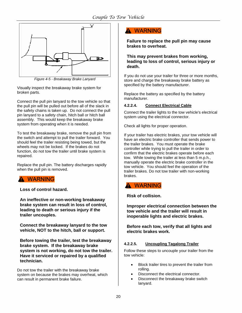
Figure 4-4 – Proper Safety Chain Connection
Inspect the safety chains and hooks for wear or damage. Replace worn or damaged safety chains and hooks before towing.
Connect the safety chains so that they:
• Cross underneath the coupler. The safety chains can hold the tongue up above the road if the trailer uncouples.
• Loop around a frame member of the tow vehicle or to holes provided in the hitch system. Do not attach them to an interchangeable part of the hitch assembly.
• If equipped with “S” hooks insert hooks up from underneath the hole.
• Provide enough slack to permit tight turns, but not be close to the road surface to drag.
Loss of control hazard. Improperly connected or failure to connect the safety chains can result in loss of control of the trailer and tow vehicle, leading to death or serious injury, if the trailer uncouples from the tow vehicle.
Fasten chains to frame of tow vehicle. Do not fasten chains to any part of the hitch unless the hitch has holes or loops specifically for that purpose. Cross chains under hitch and coupler with enough slack to permit turning and to hold tongue up, if the trailer uncoupled.
4.2.2.3. Attach And Test Electric Breakaway Brake System
If the trailer uncoupled, a properly connected and working breakaway brake system will apply electric brakes on the trailer. The safety chains will keep the tow vehicle attached and as the brakes are applied at the trailer’s axles, allowing the trailer/tow vehicle combination to come to a controlled stop. Read and follow the instructions in this manual and the instructions provided by the breakaway brake manufacturer. If you do not have these instructions, call Double D Trailers at 252-568-4042 for assistance. The breakaway brake system may be fitted with a charge line that draws power from the tow vehicle. If the electrical system on your tow vehicle does not provide power to the breakaway brake battery, you must periodically charge the battery.
Notice
^ WARNING
Couple To Tow Vehicle
20
Figure 4-5 - Breakaway Brake Lanyard Visually inspect the breakaway brake system for broken parts. Connect the pull pin lanyard to the tow vehicle so that the pull pin will be pulled out before all of the slack in the safety chains is taken up. Do not connect the pull pin lanyard to a safety chain, hitch ball or hitch ball assembly. This would keep the breakaway brake system from operating when it is needed. To test the breakaway brake, remove the pull pin from the switch and attempt to pull the trailer forward. You should feel the trailer resisting being towed, but the wheels may not be locked. If the brakes do not function, do not tow the trailer until brake system is repaired. Replace the pull pin. The battery discharges rapidly when the pull pin is removed.
Loss of control hazard. An ineffective or non-working breakaway brake system can result in loss of control, leading to death or serious injury if the trailer uncouples. Connect the breakaway lanyard to the tow vehicle, NOT to the hitch, ball or support. Before towing the trailer, test the breakaway brake system. If the breakaway brake system is not working, do not tow the trailer. Have it serviced or repaired by a qualified technician.
Do not tow the trailer with the breakaway brake system on because the brakes may overheat, which can result in permanent brake failure.
Failure to replace the pull pin may cause brakes to overheat. This may prevent brakes from working, leading to loss of control, serious injury or death.
If you do not use your trailer for three or more months, store and charge the breakaway brake battery as specified by the battery manufacturer. Replace the battery as specified by the battery manufacturer.
4.2.2.4. Connect Electrical Cable
Connect the trailer lights to the tow vehicle's electrical system using the electrical connector. Check all lights for proper operation. If your trailer has electric brakes, your tow vehicle will have an electric brake controller that sends power to the trailer brakes. You must operate the brake controller while trying to pull the trailer in order to confirm that the electric brakes operate before each tow. While towing the trailer at less than 5 m.p.h., manually operate the electric brake controller in the tow vehicle. You should feel the operation of the trailer brakes. Do not tow trailer with non-working brakes.
Risk of collision. Improper electrical connection between the tow vehicle and the trailer will result in inoperable lights and electric brakes. Before each tow, verify that all lights and electric brakes work.
4.2.2.5. Uncoupling Tagalong Trailer
Follow these steps to uncouple your trailer from the tow vehicle:
• Block trailer tires to prevent the trailer from rolling.
• Disconnect the electrical connector. • Disconnect the breakaway brake switch
lanyard.
^ WARNING
^ WARNING
^ WARNING
Couple To Tow Vehicle
21
• Disconnect the safety chains or cables from the tow vehicle.
• Unlock the coupler and open it. • Verify the ground surface below the jack pad
will support the tongue load. • Extend the jack to raise the bottom of the
coupler above the hitch ball. • Slowly drive tow vehicle away from trailer.
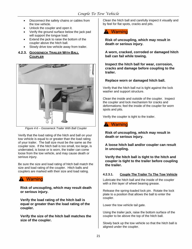
4.2.3. GOOSENECK TRAILER WITH BALL COUPLER
Figure 4-6 – Gooseneck Trailer With Ball Coupler Verify that the load rating of the hitch and ball on your tow vehicle is equal to or greater than the load rating of your trailer. The ball size must be the same as the coupler size. If the hitch ball is too small, too large, is underrated, is loose or is worn, the trailer can come loose from the tow vehicle, and may cause death or serious injury. Be sure the size and load rating of hitch ball match the size and load rating of the coupler. Hitch balls and couplers are marked with their size and load rating.
Risk of uncoupling, which may result death or serious injury. Verify the load rating of the hitch ball is equal or greater than the load rating of the coupler. Verify the size of the hitch ball matches the size of the coupler.
Clean the hitch ball and carefully inspect it visually and by feel for flat spots, cracks and pits.
Risk of uncoupling, which may result in death or serious injury. A worn, cracked, corroded or damaged hitch ball can fail while towing. Inspect the hitch ball for wear, corrosion, cracks and damage before coupling to the trailer. Replace worn or damaged hitch ball.
Verify that the hitch ball nut is tight against the lock washer and support structure. Clean the inside and outside of the coupler. Inspect the coupler and lock mechanism for cracks and deformations; feel the inside of the coupler for worn spots and pits. Verify the coupler is tight to the trailer.
Risk of uncoupling, which may result in death or serious injury. A loose hitch ball and/or coupler can result in uncoupling. Verify the hitch ball is tight to the hitch and coupler is tight to the trailer before coupling the trailer.
4.2.3.1. Couple The Trailer To The Tow Vehicle
Lubricate the hitch ball and the inside of the coupler with a thin layer of wheel bearing grease. Release the spring-loaded lock pin. Rotate the lock plate to a position that allows the ball to enter the coupler. Lower the tow vehicle tail gate. Using the trailer jack, raise the bottom surface of the coupler to be above the top of the hitch ball. Slowly back up the tow vehicle so that the hitch ball is aligned under the coupler.
^ Warning
^ Warning
^ Warning
Couple To Tow Vehicle
22
Risk of crushing. Death or serious injury may result if the trailer drops. Do not allow anyone under the trailer or coupler before or during the coupling operation.
Using the jack, lower the trailer until the coupler fully engages the hitch ball. If the coupler does not line up with the hitch ball, adjust the position of the tow vehicle. Close the lock plate on the coupler. Move the spring-loaded lock pin to the CLOSED position. Be sure the locking pin is holding the lock plate. Be sure the coupler is all the way down on the hitch ball and the lock plate is engaged. A properly engaged locking mechanism will allow the coupler to raise the rear of the tow vehicle. Using the trailer jack, test to see that you can raise the rear of the tow vehicle by 1 inch.
Overloading can damage the trailer jack. Do not use the jack to raise the tow vehicle more than 1 inch.
If the coupler cannot be secured to the hitch ball, do not tow the trailer. Contact Double D Trailers at 252-568-4042 for assistance. Retract the jack to its fully retracted position.
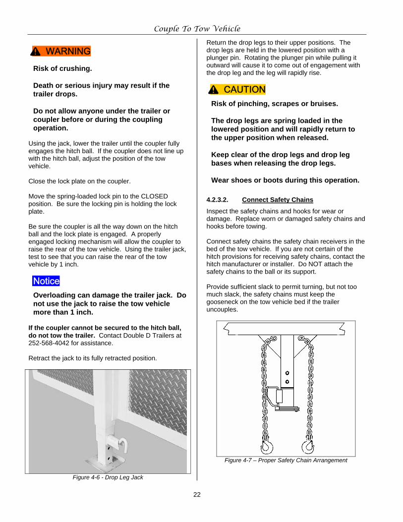
Figure 4-6 - Drop Leg Jack
Return the drop legs to their upper positions. The drop legs are held in the lowered position with a plunger pin. Rotating the plunger pin while pulling it outward will cause it to come out of engagement with the drop leg and the leg will rapidly rise.
Risk of pinching, scrapes or bruises. The drop legs are spring loaded in the lowered position and will rapidly return to the upper position when released.
Keep clear of the drop legs and drop leg bases when releasing the drop legs. Wear shoes or boots during this operation.
4.2.3.2. Connect Safety Chains
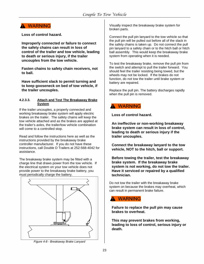
Inspect the safety chains and hooks for wear or damage. Replace worn or damaged safety chains and hooks before towing. Connect safety chains the safety chain receivers in the bed of the tow vehicle. If you are not certain of the hitch provisions for receiving safety chains, contact the hitch manufacturer or installer. Do NOT attach the safety chains to the ball or its support. Provide sufficient slack to permit turning, but not too much slack, the safety chains must keep the gooseneck on the tow vehicle bed if the trailer uncouples.
Figure 4-7 – Proper Safety Chain Arrangement
^ WARNING
Notice
^ CAUTION
Couple To Tow Vehicle
23
Loss of control hazard. Improperly connected or failure to connect the safety chains can result in loss of control of the trailer and tow vehicle, leading to death or serious injury, if the trailer uncouples from the tow vehicle.
Fasten chains to safety chain receivers, not to ball. Have sufficient slack to permit turning and to keep gooseneck on bed of tow vehicle, if the trailer uncouples.
4.2.3.3. Attach and Test The Breakaway Brake System
If the trailer uncouples, a properly connected and working breakaway brake system will apply electric brakes on the trailer. The safety chains will keep the tow vehicle attached and as the brakes are applied at the trailer’s axles, the trailer/tow vehicle combination will come to a controlled stop. Read and follow the instructions here as well as the instructions provided by the breakaway brake controller manufacturer. If you do not have these instructions, call Double D Trailers at 252-568-4042 for assistance. The breakaway brake system may be fitted with a charge line that draws power from the tow vehicle. If the electrical system on your tow vehicle does not provide power to the breakaway brake battery, you must periodically charge the battery.
Figure 4-8 - Breakaway Brake Lanyard
Visually inspect the breakaway brake system for broken parts. Connect the pull pin lanyard to the tow vehicle so that the pull pin will be pulled out before all of the slack in the safety chains is taken up. Do not connect the pull pin lanyard to a safety chain or to the hitch ball or hitch ball assembly. This would keep the breakaway brake system from operating when it is needed. To test the breakaway brake, remove the pull pin from the switch and attempt to pull the trailer forward. You should feel the trailer resisting being towed, but the wheels may not be locked. If the brakes do not function, do not tow the trailer until brake system or battery are repaired. Replace the pull pin. The battery discharges rapidly when the pull pin is removed.
Loss of control hazard. An ineffective or non-working breakaway brake system can result in loss of control, leading to death or serious injury if the trailer uncouples. Connect the breakaway lanyard to the tow vehicle, NOT to the hitch, ball or support. Before towing the trailer, test the breakaway brake system. If the breakaway brake system is not working, do not tow the trailer. Have it serviced or repaired by a qualified technician.
Do not tow the trailer with the breakaway brake system on because the brakes may overheat, which can result in permanent brake failure.
Failure to replace the pull pin may cause brakes to overheat. This may prevent brakes from working, leading to loss of control, serious injury or death.
^ WARNING
^ WARNING
^ WARNING
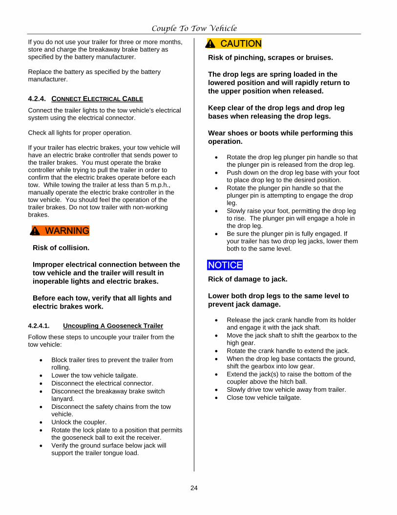
Couple To Tow Vehicle
24
If you do not use your trailer for three or more months, store and charge the breakaway brake battery as specified by the battery manufacturer. Replace the battery as specified by the battery manufacturer.
4.2.4. CONNECT ELECTRICAL CABLE Connect the trailer lights to the tow vehicle's electrical system using the electrical connector. Check all lights for proper operation. If your trailer has electric brakes, your tow vehicle will have an electric brake controller that sends power to the trailer brakes. You must operate the brake controller while trying to pull the trailer in order to confirm that the electric brakes operate before each tow. While towing the trailer at less than 5 m.p.h., manually operate the electric brake controller in the tow vehicle. You should feel the operation of the trailer brakes. Do not tow trailer with non-working brakes.
Risk of collision. Improper electrical connection between the tow vehicle and the trailer will result in inoperable lights and electric brakes. Before each tow, verify that all lights and electric brakes work.
4.2.4.1. Uncoupling A Gooseneck Trailer
Follow these steps to uncouple your trailer from the tow vehicle:
• Block trailer tires to prevent the trailer from rolling.
• Lower the tow vehicle tailgate. • Disconnect the electrical connector. • Disconnect the breakaway brake switch
lanyard. • Disconnect the safety chains from the tow
vehicle. • Unlock the coupler. • Rotate the lock plate to a position that permits
the gooseneck ball to exit the receiver. • Verify the ground surface below jack will
support the trailer tongue load.
Risk of pinching, scrapes or bruises. The drop legs are spring loaded in the lowered position and will rapidly return to the upper position when released.
Keep clear of the drop legs and drop leg bases when releasing the drop legs. Wear shoes or boots while performing this operation.
• Rotate the drop leg plunger pin handle so that
the plunger pin is released from the drop leg. • Push down on the drop leg base with your foot
to place drop leg to the desired position. • Rotate the plunger pin handle so that the
plunger pin is attempting to engage the drop leg.
• Slowly raise your foot, permitting the drop leg to rise. The plunger pin will engage a hole in the drop leg.
• Be sure the plunger pin is fully engaged. If your trailer has two drop leg jacks, lower them both to the same level.
Rick of damage to jack. Lower both drop legs to the same level to prevent jack damage.
• Release the jack crank handle from its holder
and engage it with the jack shaft. • Move the jack shaft to shift the gearbox to the
high gear. • Rotate the crank handle to extend the jack. • When the drop leg base contacts the ground,
shift the gearbox into low gear. • Extend the jack(s) to raise the bottom of the
coupler above the hitch ball. • Slowly drive tow vehicle away from trailer. • Close tow vehicle tailgate.
^ WARNING
^ CAUTION
NOTICE
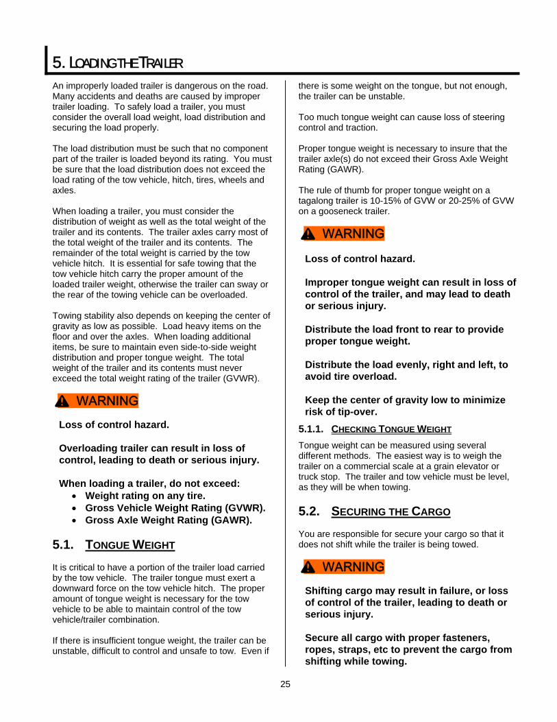
25
5. LOADING THE TRAILER An improperly loaded trailer is dangerous on the road. Many accidents and deaths are caused by improper trailer loading. To safely load a trailer, you must consider the overall load weight, load distribution and securing the load properly. The load distribution must be such that no component part of the trailer is loaded beyond its rating. You must be sure that the load distribution does not exceed the load rating of the tow vehicle, hitch, tires, wheels and axles. When loading a trailer, you must consider the distribution of weight as well as the total weight of the trailer and its contents. The trailer axles carry most of the total weight of the trailer and its contents. The remainder of the total weight is carried by the tow vehicle hitch. It is essential for safe towing that the tow vehicle hitch carry the proper amount of the loaded trailer weight, otherwise the trailer can sway or the rear of the towing vehicle can be overloaded. Towing stability also depends on keeping the center of gravity as low as possible. Load heavy items on the floor and over the axles. When loading additional items, be sure to maintain even side-to-side weight distribution and proper tongue weight. The total weight of the trailer and its contents must never exceed the total weight rating of the trailer (GVWR).
Loss of control hazard. Overloading trailer can result in loss of control, leading to death or serious injury. When loading a trailer, do not exceed:
• Weight rating on any tire. • Gross Vehicle Weight Rating (GVWR). • Gross Axle Weight Rating (GAWR).
5.1. TONGUE WEIGHT It is critical to have a portion of the trailer load carried by the tow vehicle. The trailer tongue must exert a downward force on the tow vehicle hitch. The proper amount of tongue weight is necessary for the tow vehicle to be able to maintain control of the tow vehicle/trailer combination. If there is insufficient tongue weight, the trailer can be unstable, difficult to control and unsafe to tow. Even if
there is some weight on the tongue, but not enough, the trailer can be unstable. Too much tongue weight can cause loss of steering control and traction. Proper tongue weight is necessary to insure that the trailer axle(s) do not exceed their Gross Axle Weight Rating (GAWR). The rule of thumb for proper tongue weight on a tagalong trailer is 10-15% of GVW or 20-25% of GVW on a gooseneck trailer.
Loss of control hazard. Improper tongue weight can result in loss of control of the trailer, and may lead to death or serious injury. Distribute the load front to rear to provide proper tongue weight. Distribute the load evenly, right and left, to avoid tire overload. Keep the center of gravity low to minimize risk of tip-over.
5.1.1. CHECKING TONGUE WEIGHT Tongue weight can be measured using several different methods. The easiest way is to weigh the trailer on a commercial scale at a grain elevator or truck stop. The trailer and tow vehicle must be level, as they will be when towing.
5.2. SECURING THE CARGO You are responsible for secure your cargo so that it does not shift while the trailer is being towed.
Shifting cargo may result in failure, or loss of control of the trailer, leading to death or serious injury. Secure all cargo with proper fasteners, ropes, straps, etc to prevent the cargo from shifting while towing.
^ WARNING
^ WARNING
^ WARNING
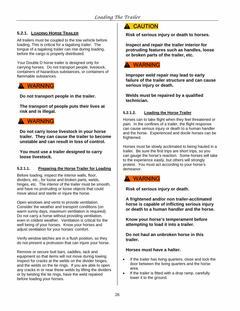
Loading The Trailer
26
5.2.1. LOADING HORSE TRAILER All trailers must be coupled to the tow vehicle before loading. This is critical for a tagalong trailer. The tongue of a tagalong trailer can rise during loading, before the cargo is properly distributed. Your Double D horse trailer is designed only for carrying horses. Do not transport people, livestock, containers of hazardous substances, or containers of flammable substances.
Do not transport people in the trailer. The transport of people puts their lives at risk and is illegal.
Do not carry loose livestock in your horse trailer. They can cause the trailer to become unstable and can result in loss of control. You must use a trailer designed to carry loose livestock.
5.2.1.1. Preparing the Horse Trailer for Loading
Before loading, inspect the interior walls, floor, dividers, etc., for loose and broken parts, welds, hinges, etc. The interior of the trailer must be smooth, and have no protruding or loose objects that could move about and startle or injure the horse. Open windows and vents to provide ventilation. Consider the weather and transport conditions (on warm sunny days, maximum ventilation is required). Do not carry a horse without providing ventilation, even in coldest weather. Ventilation is critical for the well being of your horses. Know your horses and adjust ventilation for your horses’ comfort. Verify window latches are in a flush position, so they do not present a protrusion that can injure your horse. Remove or secure butt bars, saddles, tack and equipment so that items will not move during towing. Inspect for cracks at the welds on the divider hinges, and the welds on the tie rings. If you are able to open any cracks in or near these welds by lifting the dividers or by twisting the tie rings, have the weld repaired before loading your horses.
Risk of serious injury or death to horses. Inspect and repair the trailer interior for protruding features such as handles, loose or broken parts of the trailer, etc.
Improper weld repair may lead to early failure of the trailer structure and can cause serious injury or death. Welds must be repaired by a qualified technician.
5.2.1.2. Loading the Horse Trailer
Horses can to take flight when they feel threatened or pain. In the confines of a trailer, the flight response can cause serious injury or death to a human handler and the horse. Experienced and docile horses can be frightened. Horses must be slowly acclimated to being hauled in a trailer. Be sure the first trips are short trips, so you can gauge the horse’s reaction. Some horses will take to the experience easily, but others will strongly protest. You must act according to your horse’s demeanor.
Risk of serious injury or death. A frightened and/or non trailer-acclimated horse is capable of inflicting serious injury or death to a human handler and the horse. Know your horse’s temperament before attempting to load it into a trailer.
Do not haul an unbroken horse in this trailer. Horses must have a halter.
• If the trailer has living quarters, close and lock the
door between the living quarters and the horse area.
• If the trailer is fitted with a drop ramp, carefully lower it to the ground.
^ WARNING
^ WARNING
^ CAUTION
^ WARNING
^ WARNING
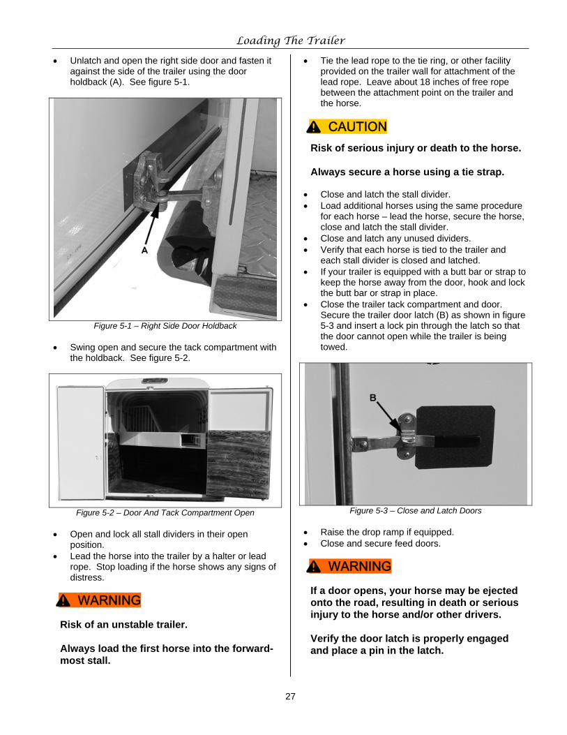
Loading The Trailer
27
• Unlatch and open the right side door and fasten it against the side of the trailer using the door holdback (A). See figure 5-1.
Figure 5-1 – Right Side Door Holdback • Swing open and secure the tack compartment with
the holdback. See figure 5-2.
Figure 5-2 – Door And Tack Compartment Open • Open and lock all stall dividers in their open
position. • Lead the horse into the trailer by a halter or lead
rope. Stop loading if the horse shows any signs of distress.
Risk of an unstable trailer. Always load the first horse into the forward-most stall.
• Tie the lead rope to the tie ring, or other facility provided on the trailer wall for attachment of the lead rope. Leave about 18 inches of free rope between the attachment point on the trailer and the horse.
Risk of serious injury or death to the horse. Always secure a horse using a tie strap.
• Close and latch the stall divider. • Load additional horses using the same procedure
for each horse – lead the horse, secure the horse, close and latch the stall divider.
• Close and latch any unused dividers. • Verify that each horse is tied to the trailer and
each stall divider is closed and latched. • If your trailer is equipped with a butt bar or strap to
keep the horse away from the door, hook and lock the butt bar or strap in place.
• Close the trailer tack compartment and door. Secure the trailer door latch (B) as shown in figure 5-3 and insert a lock pin through the latch so that the door cannot open while the trailer is being towed.
Figure 5-3 – Close and Latch Doors • Raise the drop ramp if equipped. • Close and secure feed doors.
If a door opens, your horse may be ejected onto the road, resulting in death or serious injury to the horse and/or other drivers. Verify the door latch is properly engaged and place a pin in the latch.
^ WARNING
^ CAUTION
^ WARNING
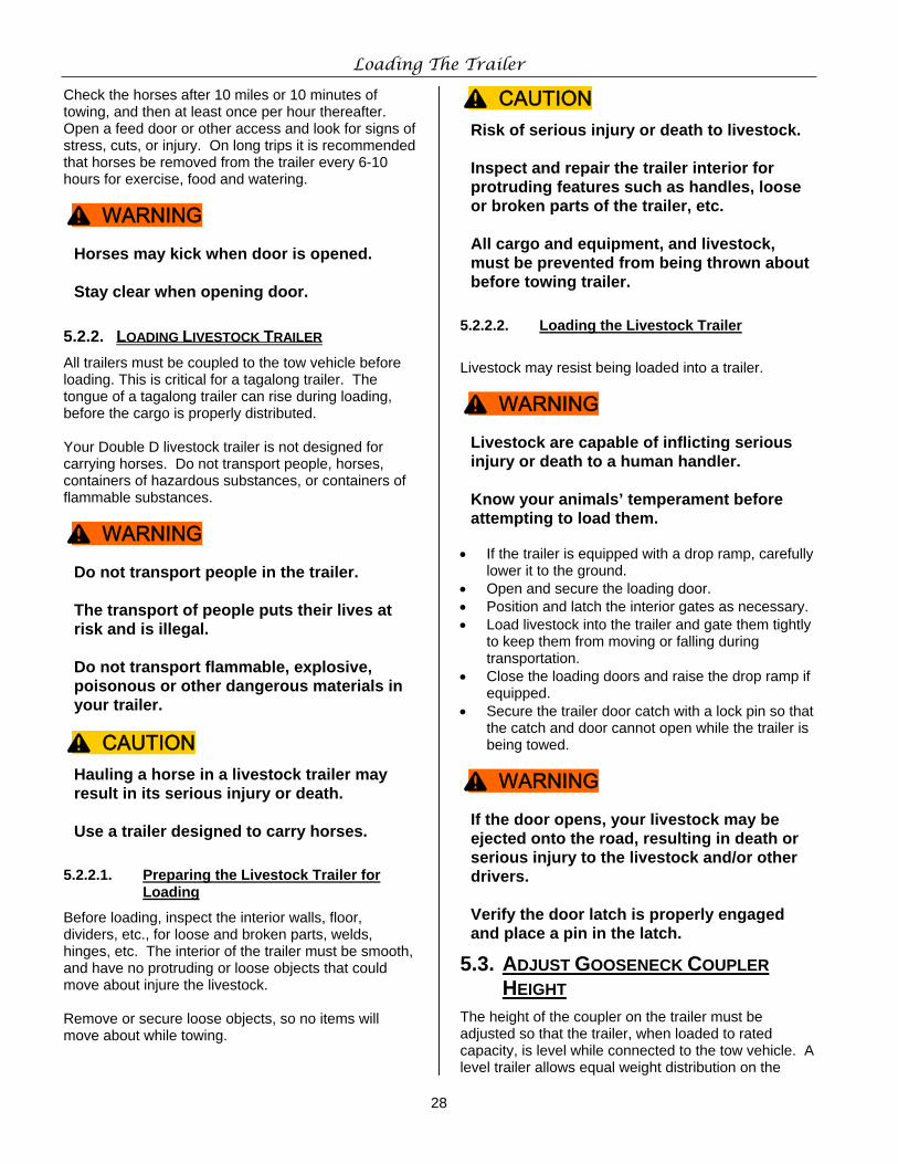
Loading The Trailer
28
Check the horses after 10 miles or 10 minutes of towing, and then at least once per hour thereafter. Open a feed door or other access and look for signs of stress, cuts, or injury. On long trips it is recommended that horses be removed from the trailer every 6-10 hours for exercise, food and watering.
Horses may kick when door is opened. Stay clear when opening door.
5.2.2. LOADING LIVESTOCK TRAILER All trailers must be coupled to the tow vehicle before loading. This is critical for a tagalong trailer. The tongue of a tagalong trailer can rise during loading, before the cargo is properly distributed. Your Double D livestock trailer is not designed for carrying horses. Do not transport people, horses, containers of hazardous substances, or containers of flammable substances.
Do not transport people in the trailer. The transport of people puts their lives at risk and is illegal. Do not transport flammable, explosive, poisonous or other dangerous materials in your trailer.
Hauling a horse in a livestock trailer may result in its serious injury or death. Use a trailer designed to carry horses.
5.2.2.1. Preparing the Livestock Trailer for Loading
Before loading, inspect the interior walls, floor, dividers, etc., for loose and broken parts, welds, hinges, etc. The interior of the trailer must be smooth, and have no protruding or loose objects that could move about injure the livestock. Remove or secure loose objects, so no items will move about while towing.
Risk of serious injury or death to livestock. Inspect and repair the trailer interior for protruding features such as handles, loose or broken parts of the trailer, etc. All cargo and equipment, and livestock, must be prevented from being thrown about before towing trailer.
5.2.2.2. Loading the Livestock Trailer
Livestock may resist being loaded into a trailer.
Livestock are capable of inflicting serious injury or death to a human handler. Know your animals’ temperament before attempting to load them.
• If the trailer is equipped with a drop ramp, carefully
lower it to the ground. • Open and secure the loading door. • Position and latch the interior gates as necessary. • Load livestock into the trailer and gate them tightly
to keep them from moving or falling during transportation.
• Close the loading doors and raise the drop ramp if equipped.
• Secure the trailer door catch with a lock pin so that the catch and door cannot open while the trailer is being towed.
If the door opens, your livestock may be ejected onto the road, resulting in death or serious injury to the livestock and/or other drivers. Verify the door latch is properly engaged and place a pin in the latch.
5.3. ADJUST GOOSENECK COUPLER HEIGHT
The height of the coupler on the trailer must be adjusted so that the trailer, when loaded to rated capacity, is level while connected to the tow vehicle. A level trailer allows equal weight distribution on the
^ WARNING
^ WARNING
^ CAUTION
^ CAUTION
^ WARNING
^ WARNING
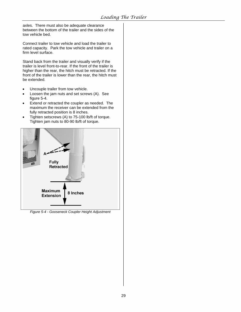
Loading The Trailer
29
axles. There must also be adequate clearance between the bottom of the trailer and the sides of the tow vehicle bed. Connect trailer to tow vehicle and load the trailer to rated capacity. Park the tow vehicle and trailer on a firm level surface. Stand back from the trailer and visually verify if the trailer is level front-to-rear. If the front of the trailer is higher than the rear, the hitch must be retracted. If the front of the trailer is lower than the rear, the hitch must be extended. • Uncouple trailer from tow vehicle. • Loosen the jam nuts and set screws (A). See
figure 5-4. • Extend or retracted the coupler as needed. The
maximum the receiver can be extended from the fully retracted position is 8 inches.
• Tighten setscrews (A) to 75-100 lb/ft of torque. Tighten jam nuts to 80-90 lb/ft of torque.
Figure 5-4 - Gooseneck Coupler Height Adjustment
30
6. PRE-TRIP CHECKLIST
6.1. PRE-TRIP CHECKLIST Before towing the trailer, check all of following items. • Tires and wheels for damage and wear. • Lug nuts tightness (torque). • Tire air pressure. • Coupler secured and locked. • Safety chains properly connected to tow vehicle,
not to hitch or ball. • Test all trailer lights. Repair non-working lights
before towing. • Test trailer brakes. Have non-working brakes
repaired by a qualified technician before towing. • Safety breakaway switch lanyard fastened to tow
vehicle, not to safety chains. • Cargo properly loaded, weight distributed
properly and secured. • Check tongue weight. Adjust load if not correct. • Check hitch height. Adjust hitch height if
necessary. • All doors and gates latched and secured. • Fire extinguisher properly charged (trailer
equipped with living quarters). • Flares and reflectors.
6.2. MAKE REGULAR INSPECTION STOPS
After each 50 miles, or one hour of towing, stop and check the following items: • Coupler locked and secured. • Safety chains are fastened and not dragging or
damaged. • Cargo properly secured. • All doors latched and secured.
31
7. TRAILER BREAK-IN
7.1. CHECK WHEEL LUG NUTS Wheel lugs can shift and settle quickly after being first assembled, and must be checked after the first 10, 25 and 50 miles of driving. Failure to perform this check may result in a wheel separating from the trailer, causing a crash leading to death or serious injury.
Lug nuts are prone to loosen after initial installation, which can lead to death or serious injury. Check lug nuts for tightness on a new trailer or when wheel(s) have been remounted after the first 10, 25 and 50 miles of driving.
7.2. ADJUST BRAKES AT FIRST 200 MILES
Brake shoes and drums experience a rapid initial wear. The brakes must be adjusted after the first 200 miles of use, and each 3,000 miles thereafter. Some axles are fitted with a mechanism that will automatically adjust the brake shoes when the trailer is “hard braked” from a rearward direction. Read your axle and brake manual to see if your brakes adjust automatically. If you do not have the axle and brake manual, call Double D Trailers at 252-568-4042 for assistance. If your trailer is not equipped with automatic adjusting brakes, the brakes will need to be manually adjusted. See Section 8 for instructions.
7.3. SYNCHRONIZING THE BRAKE SYSTEMS
Trailer brakes are designed to work in synchronization with the brakes on the tow vehicle. When the tow vehicle and trailer braking systems are synchronized, both braking systems contribute to slowing, and the tongue of the trailer will not dive or raise.
Loss of control hazard, resulting in death or serious injury. The trailer and tow vehicle brakes must be synchronized. Test the brakes in a safe area at no more than 30 m.p.h. before each tow.
To insure safe brake performance and synchronization, read and follow the axle/brake and the brake controller manufacturers’ instructions. If you do not have these instructions, call Double D Trailers at 252-568-4042 for assistance.
7.4. TIRE PRESSURE Check tire pressures on both the trailer and tow vehicle. Inflate to the psi indicated on the respective VIN / Certification Label or on the tire sidewall.
^ WARNING
^ WARNING
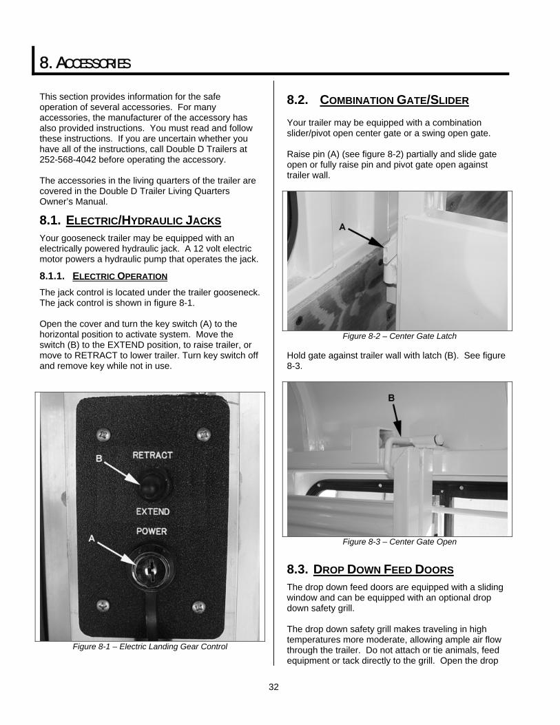
32
8. ACCESSORIES This section provides information for the safe operation of several accessories. For many accessories, the manufacturer of the accessory has also provided instructions. You must read and follow these instructions. If you are uncertain whether you have all of the instructions, call Double D Trailers at 252-568-4042 before operating the accessory. The accessories in the living quarters of the trailer are covered in the Double D Trailer Living Quarters Owner’s Manual.
8.1. ELECTRIC/HYDRAULIC JACKS Your gooseneck trailer may be equipped with an electrically powered hydraulic jack. A 12 volt electric motor powers a hydraulic pump that operates the jack.
8.1.1. ELECTRIC OPERATION The jack control is located under the trailer gooseneck. The jack control is shown in figure 8-1. Open the cover and turn the key switch (A) to the horizontal position to activate system. Move the switch (B) to the EXTEND position, to raise trailer, or move to RETRACT to lower trailer. Turn key switch off and remove key while not in use.
Figure 8-1 – Electric Landing Gear Control
8.2. COMBINATION GATE/SLIDER Your trailer may be equipped with a combination slider/pivot open center gate or a swing open gate. Raise pin (A) (see figure 8-2) partially and slide gate open or fully raise pin and pivot gate open against trailer wall.
Figure 8-2 – Center Gate Latch
Hold gate against trailer wall with latch (B). See figure 8-3.
Figure 8-3 – Center Gate Open
8.3. DROP DOWN FEED DOORS The drop down feed doors are equipped with a sliding window and can be equipped with an optional drop down safety grill. The drop down safety grill makes traveling in high temperatures more moderate, allowing ample air flow through the trailer. Do not attach or tie animals, feed equipment or tack directly to the grill. Open the drop
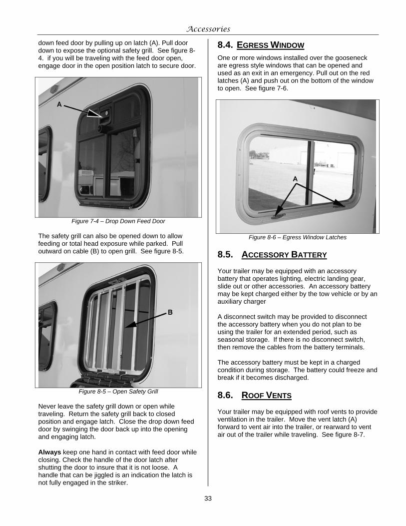
Accessories
33
down feed door by pulling up on latch (A). Pull door down to expose the optional safety grill. See figure 8-4. if you will be traveling with the feed door open, engage door in the open position latch to secure door.
Figure 7-4 – Drop Down Feed Door The safety grill can also be opened down to allow feeding or total head exposure while parked. Pull outward on cable (B) to open grill. See figure 8-5.
Figure 8-5 – Open Safety Grill Never leave the safety grill down or open while traveling. Return the safety grill back to closed position and engage latch. Close the drop down feed door by swinging the door back up into the opening and engaging latch. Always keep one hand in contact with feed door while closing. Check the handle of the door latch after shutting the door to insure that it is not loose. A handle that can be jiggled is an indication the latch is not fully engaged in the striker.
8.4. EGRESS WINDOW One or more windows installed over the gooseneck are egress style windows that can be opened and used as an exit in an emergency. Pull out on the red latches (A) and push out on the bottom of the window to open. See figure 7-6.
Figure 8-6 – Egress Window Latches
8.5. ACCESSORY BATTERY Your trailer may be equipped with an accessory battery that operates lighting, electric landing gear, slide out or other accessories. An accessory battery may be kept charged either by the tow vehicle or by an auxiliary charger A disconnect switch may be provided to disconnect the accessory battery when you do not plan to be using the trailer for an extended period, such as seasonal storage. If there is no disconnect switch, then remove the cables from the battery terminals. The accessory battery must be kept in a charged condition during storage. The battery could freeze and break if it becomes discharged.
8.6. ROOF VENTS Your trailer may be equipped with roof vents to provide ventilation in the trailer. Move the vent latch (A) forward to vent air into the trailer, or rearward to vent air out of the trailer while traveling. See figure 8-7.
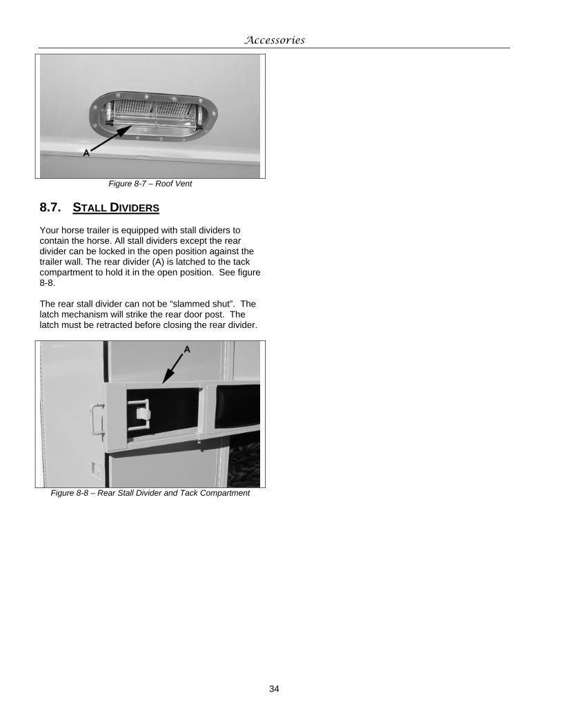
Accessories
34
Figure 8-7 – Roof Vent
8.7. STALL DIVIDERS Your horse trailer is equipped with stall dividers to contain the horse. All stall dividers except the rear divider can be locked in the open position against the trailer wall. The rear divider (A) is latched to the tack compartment to hold it in the open position. See figure 8-8. The rear stall divider can not be “slammed shut”. The latch mechanism will strike the rear door post. The latch must be retracted before closing the rear divider.
Figure 8-8 – Rear Stall Divider and Tack Compartment
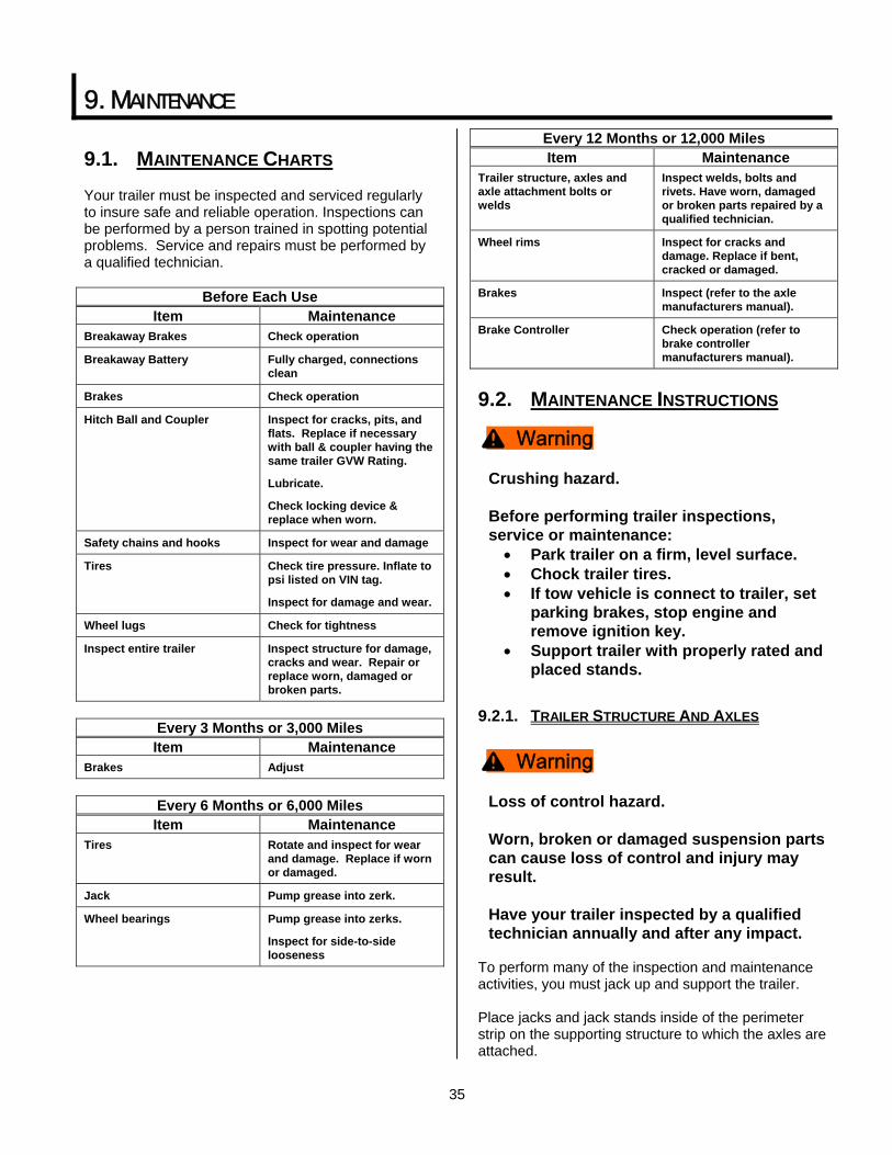
35
9. MAINTENANCE
9.1. MAINTENANCE CHARTS Your trailer must be inspected and serviced regularly to insure safe and reliable operation. Inspections can be performed by a person trained in spotting potential problems. Service and repairs must be performed by a qualified technician.
Before Each Use Item Maintenance
Breakaway Brakes Check operation
Breakaway Battery Fully charged, connections clean
Brakes Check operation
Hitch Ball and Coupler Inspect for cracks, pits, and flats. Replace if necessary with ball & coupler having the same trailer GVW Rating.
Lubricate.
Check locking device & replace when worn.
Safety chains and hooks Inspect for wear and damage
Tires Check tire pressure. Inflate to psi listed on VIN tag.
Inspect for damage and wear.
Wheel lugs Check for tightness
Inspect entire trailer Inspect structure for damage, cracks and wear. Repair or replace worn, damaged or broken parts.
Every 3 Months or 3,000 Miles Item Maintenance
Brakes Adjust
Every 6 Months or 6,000 Miles Item Maintenance
Tires Rotate and inspect for wear and damage. Replace if worn or damaged.
Jack Pump grease into zerk.
Wheel bearings Pump grease into zerks.
Inspect for side-to-side looseness
Every 12 Months or 12,000 Miles Item Maintenance
Trailer structure, axles and axle attachment bolts or welds
Inspect welds, bolts and rivets. Have worn, damaged or broken parts repaired by a qualified technician.
Wheel rims Inspect for cracks and damage. Replace if bent, cracked or damaged.
Brakes Inspect (refer to the axle manufacturers manual).
Brake Controller Check operation (refer to brake controller manufacturers manual).
9.2. MAINTENANCE INSTRUCTIONS
Crushing hazard. Before performing trailer inspections, service or maintenance: • Park trailer on a firm, level surface. • Chock trailer tires. • If tow vehicle is connect to trailer, set
parking brakes, stop engine and remove ignition key.
• Support trailer with properly rated and placed stands.
9.2.1. TRAILER STRUCTURE AND AXLES
Loss of control hazard. Worn, broken or damaged suspension parts can cause loss of control and injury may result. Have your trailer inspected by a qualified technician annually and after any impact.
To perform many of the inspection and maintenance activities, you must jack up and support the trailer. Place jacks and jack stands inside of the perimeter strip on the supporting structure to which the axles are attached.
^ Warning
^ Warning
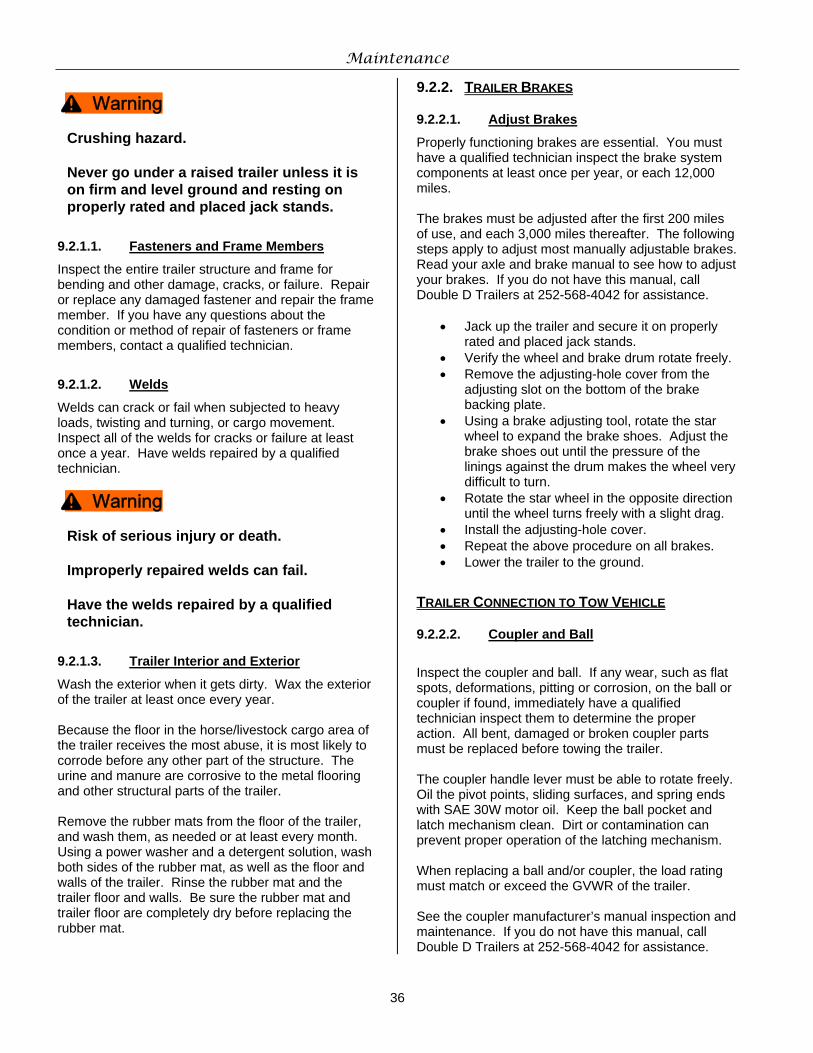
Maintenance
36
Crushing hazard. Never go under a raised trailer unless it is on firm and level ground and resting on properly rated and placed jack stands.
9.2.1.1. Fasteners and Frame Members
Inspect the entire trailer structure and frame for bending and other damage, cracks, or failure. Repair or replace any damaged fastener and repair the frame member. If you have any questions about the condition or method of repair of fasteners or frame members, contact a qualified technician.
9.2.1.2. Welds
Welds can crack or fail when subjected to heavy loads, twisting and turning, or cargo movement. Inspect all of the welds for cracks or failure at least once a year. Have welds repaired by a qualified technician.
Risk of serious injury or death. Improperly repaired welds can fail. Have the welds repaired by a qualified technician.
9.2.1.3. Trailer Interior and Exterior
Wash the exterior when it gets dirty. Wax the exterior of the trailer at least once every year. Because the floor in the horse/livestock cargo area of the trailer receives the most abuse, it is most likely to corrode before any other part of the structure. The urine and manure are corrosive to the metal flooring and other structural parts of the trailer. Remove the rubber mats from the floor of the trailer, and wash them, as needed or at least every month. Using a power washer and a detergent solution, wash both sides of the rubber mat, as well as the floor and walls of the trailer. Rinse the rubber mat and the trailer floor and walls. Be sure the rubber mat and trailer floor are completely dry before replacing the rubber mat.
9.2.2. TRAILER BRAKES
9.2.2.1. Adjust Brakes
Properly functioning brakes are essential. You must have a qualified technician inspect the brake system components at least once per year, or each 12,000 miles. The brakes must be adjusted after the first 200 miles of use, and each 3,000 miles thereafter. The following steps apply to adjust most manually adjustable brakes. Read your axle and brake manual to see how to adjust your brakes. If you do not have this manual, call Double D Trailers at 252-568-4042 for assistance.
• Jack up the trailer and secure it on properly rated and placed jack stands.
• Verify the wheel and brake drum rotate freely. • Remove the adjusting-hole cover from the
adjusting slot on the bottom of the brake backing plate.
• Using a brake adjusting tool, rotate the star wheel to expand the brake shoes. Adjust the brake shoes out until the pressure of the linings against the drum makes the wheel very difficult to turn.
• Rotate the star wheel in the opposite direction until the wheel turns freely with a slight drag.
• Install the adjusting-hole cover. • Repeat the above procedure on all brakes. • Lower the trailer to the ground.
TRAILER CONNECTION TO TOW VEHICLE
9.2.2.2. Coupler and Ball
Inspect the coupler and ball. If any wear, such as flat spots, deformations, pitting or corrosion, on the ball or coupler if found, immediately have a qualified technician inspect them to determine the proper action. All bent, damaged or broken coupler parts must be replaced before towing the trailer. The coupler handle lever must be able to rotate freely. Oil the pivot points, sliding surfaces, and spring ends with SAE 30W motor oil. Keep the ball pocket and latch mechanism clean. Dirt or contamination can prevent proper operation of the latching mechanism. When replacing a ball and/or coupler, the load rating must match or exceed the GVWR of the trailer. See the coupler manufacturer’s manual inspection and maintenance. If you do not have this manual, call Double D Trailers at 252-568-4042 for assistance.
^ Warning
^ Warning
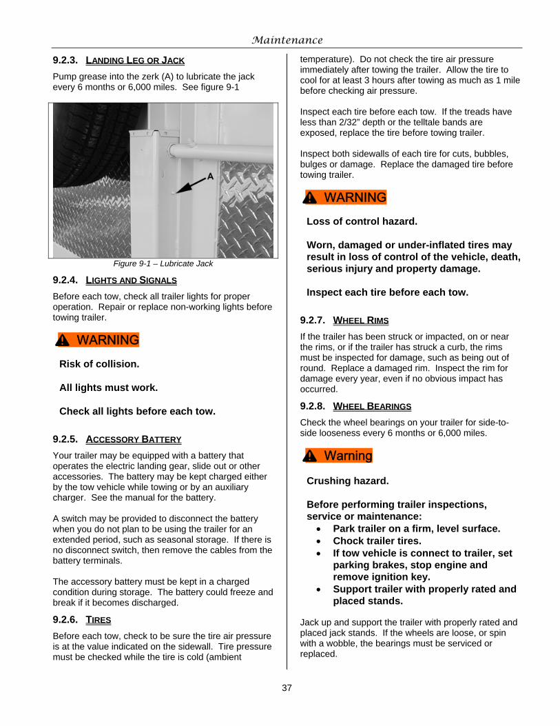
Maintenance
37
9.2.3. LANDING LEG OR JACK Pump grease into the zerk (A) to lubricate the jack every 6 months or 6,000 miles. See figure 9-1
Figure 9-1 – Lubricate Jack
9.2.4. LIGHTS AND SIGNALS Before each tow, check all trailer lights for proper operation. Repair or replace non-working lights before towing trailer.
Risk of collision. All lights must work. Check all lights before each tow.
9.2.5. ACCESSORY BATTERY Your trailer may be equipped with a battery that operates the electric landing gear, slide out or other accessories. The battery may be kept charged either by the tow vehicle while towing or by an auxiliary charger. See the manual for the battery. A switch may be provided to disconnect the battery when you do not plan to be using the trailer for an extended period, such as seasonal storage. If there is no disconnect switch, then remove the cables from the battery terminals. The accessory battery must be kept in a charged condition during storage. The battery could freeze and break if it becomes discharged.
9.2.6. TIRES Before each tow, check to be sure the tire air pressure is at the value indicated on the sidewall. Tire pressure must be checked while the tire is cold (ambient
temperature). Do not check the tire air pressure immediately after towing the trailer. Allow the tire to cool for at least 3 hours after towing as much as 1 mile before checking air pressure. Inspect each tire before each tow. If the treads have less than 2/32” depth or the telltale bands are exposed, replace the tire before towing trailer. Inspect both sidewalls of each tire for cuts, bubbles, bulges or damage. Replace the damaged tire before towing trailer.
Loss of control hazard. Worn, damaged or under-inflated tires may result in loss of control of the vehicle, death, serious injury and property damage. Inspect each tire before each tow.
9.2.7. WHEEL RIMS If the trailer has been struck or impacted, on or near the rims, or if the trailer has struck a curb, the rims must be inspected for damage, such as being out of round. Replace a damaged rim. Inspect the rim for damage every year, even if no obvious impact has occurred.
9.2.8. WHEEL BEARINGS Check the wheel bearings on your trailer for side-to-side looseness every 6 months or 6,000 miles.
Crushing hazard. Before performing trailer inspections, service or maintenance: • Park trailer on a firm, level surface. • Chock trailer tires. • If tow vehicle is connect to trailer, set
parking brakes, stop engine and remove ignition key.
• Support trailer with properly rated and placed stands.
Jack up and support the trailer with properly rated and placed jack stands. If the wheels are loose, or spin with a wobble, the bearings must be serviced or replaced.
^ WARNING
^ WARNING
^ Warning
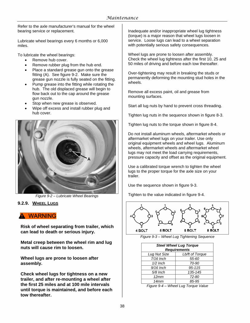
Maintenance
38
Refer to the axle manufacturer’s manual for the wheel bearing service or replacement. Lubricate wheel bearings every 6 months or 6,000 miles. To lubricate the wheel bearings:
• Remove hub cover. • Remove rubber plug from the hub end. • Place a standard grease gun onto the grease
fitting (A). See figure 9-2. Make sure the grease gun nozzle is fully seated on the fitting.
• Pump grease into the fitting while rotating the hub. The old displaced grease will begin to flow back out to the cap around the grease gun nozzle.
• Stop when new grease is observed. • Wipe off excess and install rubber plug and
hub cover.
Figure 9-2 – Lubricate Wheel Bearings
9.2.9. WHEEL LUGS
Risk of wheel separating from trailer, which can lead to death or serious injury. Metal creep between the wheel rim and lug nuts will cause rim to loosen. Wheel lugs are prone to loosen after assembly. Check wheel lugs for tightness on a new trailer, and after re-mounting a wheel after the first 25 miles and at 100 mile intervals until torque is maintained, and before each tow thereafter.
Inadequate and/or inappropriate wheel lug tightness (torque) is a major reason that wheel lugs loosen in service. Loose lugs can lead to a wheel separation with potentially serious safety consequences. Wheel lugs are prone to loosen after assembly. Check the wheel lug tightness after the first 10, 25 and 50 miles of driving and before each tow thereafter. Over-tightening may result in breaking the studs or permanently deforming the mounting stud holes in the wheels. Remove all excess paint, oil and grease from mounting surfaces. Start all lug nuts by hand to prevent cross threading. Tighten lug nuts in the sequence shown in figure 8-3. Tighten lug nuts to the torque shown in figure 8-4. Do not install aluminum wheels, aftermarket wheels or aftermarket wheel lugs on your trailer. Use only original equipment wheels and wheel lugs. Aluminum wheels, aftermarket wheels and aftermarket wheel lugs may not meet the load carrying requirements, pressure capacity and offset as the original equipment. Use a calibrated torque wrench to tighten the wheel lugs to the proper torque for the axle size on your trailer. Use the sequence shown in figure 9-3. Tighten to the value indicated in figure 9-4.
Figure 9-3 – Wheel Lug Tightening Sequence
Steel Wheel Lug Torque Requirements
Lug Nut Size Lb/ft of Torque 7/16 Inch 55-60 1/2 Inch 70-90 9/16 Inch 95-115 5/8 Inch 135-145 12mm 72-80 14mm 85-95
Figure 9-4 – Wheel Lug Torque Value
^ WARNING
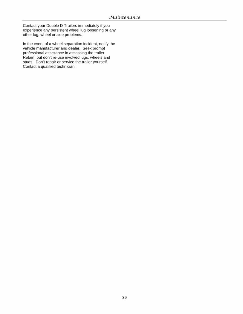
Maintenance
39
Contact your Double D Trailers immediately if you experience any persistent wheel lug loosening or any other lug, wheel or axle problems. In the event of a wheel separation incident, notify the vehicle manufacturer and dealer. Seek prompt professional assistance in assessing the trailer. Retain, but don’t re-use involved lugs, wheels and studs. Don’t repair or service the trailer yourself. Contact a qualified technician.