double biquad filter for tone detection on fixed point dsps · application report spra482...
TRANSCRIPT

Application ReportSPRA482
Digital Signal Processing Solutions February 1999
Programmable Double Biquad Filter forTone Detection on Fixed Point DSPs
Digital Signal Processing Solutions
Abstract The filters described here are user programmable double biquad filters for tone detection. Thefilters are implemented on the Texas Instruments (TIä) TMS320C2xx digital signal processor(DSP). The filter program includes an energy estimation stage. Examples of applications areCPTD (call progress tone detection), fax tone detection, answer tone detection, etc. for telephonyor modem.
Contents
Introduction ......................................................................................................................................................2
Filter Structure and Difference Equations ........................................................................................................2
Description of the Tone Detection Procedure ..................................................................................................3
Description of Filter Programs..........................................................................................................................5initFilt.c ...................................................................................................................................................5Biquad.asm...............................................................................................................................................5Summary of Programmable Parameters...................................................................................................8
Interface Between High Level Programs and the Filter Program ...................................................................10
Processor Resources Used By Filter Programs.............................................................................................11
Reference ......................................................................................................................................................11
Appendix A. Source Code.............................................................................................................................11FILE: BIQUAD.ASM................................................................................................................................11FILE: INITFILT.C.....................................................................................................................................18FILE: FILTERS.H ....................................................................................................................................21
Appendix B. Glossary....................................................................................................................................23
FiguresFigure 1. Transposed Form Cascade Structure for N=4 .................................................................................2Figure 2. Stages of the Tone Detection Operation..........................................................................................3Figure 3. Example of Filter Design for Dial Tone Detector ..............................................................................4Figure 4. Flow Chart of the Decision Stage in the Detection Process.............................................................8Figure 5. Cadence Check for Busy Tone Detection ......................................................................................10
TablesTable 1. Bit Masks For The Different Filters....................................................................................................7Table 2. Scale Factors and Corresponding Right Shift of the Input Sample ...................................................9Table 3. Detection Thresholds and Corresponding Energy Fraction...............................................................9Table 4. Processor Resources Required for the Tone Detection Module .....................................................11

Application ReportSPRA482
Programmable Double Biquad Filter for Tone Detection on Fixed Point DSPs 2
IntroductionThe aim of this report is to describe tone detection by means of a programmablepassband filter in combination with an energy estimation stage. The filtering operationdescribed below allows the detection of single frequencies (with a tolerance band of ±x%)or a frequency band (e.g., tones used in the telephone net: dial tone, busy tone, etc.). Allparameters related to the tone detection process are user programmable. Theseparameters include filter coefficients, scale factors and detection thresholds. Thefollowing sections describe the filter structure used for passband filtering , the differentsteps involved in the detection process, the software carrying out these operations, theinterface between filter programs and application S/W layer and processor resourcesrequired.
Filter Structure and Difference EquationsThis section gives a theoretical overview of the IIR filter used in the tone detectionprocess. The filter structure implemented here is the so-called transposed form cascadestructure, which is shown in Figure 1.
Figure 1. Transposed Form Cascade Structure for N=4
x[n] +
z-1
z-1
+
+
y1[n]+
z-1
z-1
+
+
d11[n]
y[n]
d12[n]
d21[n]
d22[n]
b10
b11
b12
-a11
-a12
b20
b21
b22
-a21
-a22
The corresponding difference equations are:
[ ] [ ]
[ ] [ ] [ ] [ ]
[ ] [ ] [ ]
[ ]é ù
[ ]
y x
y b y n d n
d n b y n a y n d n
d n b y n a y n
iN
y n y n
i i i i
i i i i i i
i i i i i
N
0 0
0 1 1
1 1 1 1 2
2 2 1 2
1 2
1
1
1 21
2
=
= + -
= - + -
= -
=+é
êêù
úú
=
-
-
-
+
, ,...,
( )/
(equation 1)
x[n] denotes the filter input, yi[n] is the filter output after the filter stage i and y[n] theglobal filter output. By means of a filter design tool using the filter structure shown inFigure 1 we can determine the filter coefficients of a double biquad filter (N=4) for thedesired passband. An example of filter design will be given in the next section.

Application ReportSPRA482
Programmable Double Biquad Filter for Tone Detection on Fixed Point DSPs 3
Description of the Tone Detection ProcedureThe tone detection procedure can be divided into different stages as shown in Figure 2.
Figure 2. Stages of the Tone Detection Operation
Scale x[n]
Energy estimationbased on
|y[n]|
Energy estimationbased on
|x[n]|
Decisionx[n]y[n]
First the main filtering operation is carried out. This consists of bandpass filtering thescaled input signal. This is followed by an energy estimation by means of exponentialfilters based on the filtered signal and the global signal.
The exponential filters are given by:
[ ] ( )
[ ] ( ) [ ]
FilterOut n y n FilterOut n
TotOut n x n TotOut n
= + - -
= + - -
a a
a a
[ ] [ ]
[ ]
1 1
1 1(equation 2)
The last stage consists of the decision whether a tone has been detected or not. Thedetection criteria is specified as follows
[ ]FilterOut n Threshold TotOut n[ ] ´ ³ (equation 3)
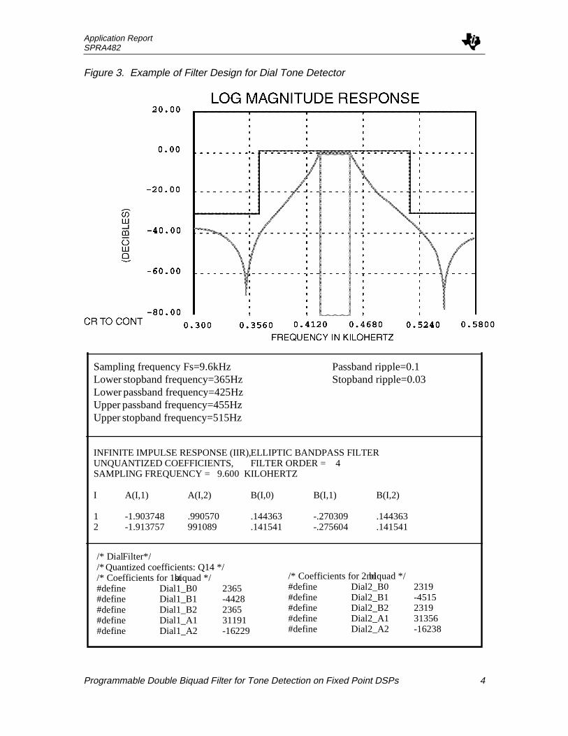
The bandpass filter is a double biquad filter based on equation 1. The filter coefficientshave to be previously determined by means of a filter design tool. The bandpass filter ischaracterized by seven parameters: the sampling frequency, the lower and upperstopband frequencies and the lower and upper passband frequencies, as well as thepassband ripple and the stopband ripple.
An example of filter design is shown in Figure 3. The filter coefficients generated by thedesign tool are stored in a C-header file, Filters.h . Before running the filter for the firsttime, initialization routines contained in the file initFilt.c have to be executed. Thedifferent programs and the interface C-Assembly language will be described in thefollowing sections.
Application ReportSPRA482
Programmable Double Biquad Filter for Tone Detection on Fixed Point DSPs 4
Figure 3. Example of Filter Design for Dial Tone Detector
Sampling frequency Fs=9.6kHzLower stopband frequency=365HzLowerpassband frequency=425HzUpper passband frequency=455HzUpper stopband frequency=515Hz
Passband ripple=0.1Stopband ripple=0.03
INFINITE IMPULSE RESPONSE (IIR),ELLIPTIC BANDPASS FILTERUNQUANTIZED COEFFICIENTS, FILTER ORDER = 4SAMPLING FREQUENCY = 9.600 KILOHERTZ
I A(I,1) A(I,2) B(I,0) B(I,1) B(I,2)
1 -1.903748 .990570 .144363 -.270309 .1443632 -1.913757 991089 .141541 -.275604 .141541
/* DialFilter*//* Quantized coefficients: Q14 *//* Coefficients for 1stbiquad */#define Dial1_B0 2365#define Dial1_B1 -4428#define Dial1_B2 2365#define Dial1_A1 31191#define Dial1_A2 -16229
/* Coefficients for 2ndbiquad */#define Dial2_B0 2319#define Dial2_B1 -4515#define Dial2_B2 2319#define Dial2_A1 31356#define Dial2_A2 -16238
Application ReportSPRA482
Programmable Double Biquad Filter for Tone Detection on Fixed Point DSPs 5
Description of Filter ProgramsThis section deals with the filter programs and the parameters that have to be determinedbefore running the filter. All parameters that directly influence detection areprogrammable. These parameters include the filter coefficients, the scale factor for theinput sample applied to the filter and the detection threshold. They can be found in the fileFilters.h , given in Appendix A. This file is used by the initialization routine initFilt.c ,described below. As an example, a filter for dial and busy tone detection is implemented.
initFilt.c
This routine initializes the filter variables with the fixed parameter values. All variablenames are chosen according to the following convention: FilterName Variable.
Example: filter name=Dial, variable=Threshold -> variable name=DialThreshold.
Each filter has the following variables:---Filter[14]: Array of fourteen elements for filter coefficients and delays---Shift: Scale factor for input sample---Threshold: Factor used in the decision stage (cf. equation 3)---In: Input to the exponential filter after bandpass filtering (|y[n]|)---Out: Output of the exponential filter applied to decision stagewhere --- stands for the filter name.
The elements of ---Filter[14] for a double biquad as shown in Figure 1 are:---Filter[0]=d11
---Filter[1]=d12
---Filter[2]=d21
---Filter[3]=d22
---Filter[4]=b10
---Filter[5]=b11
---Filter[6]=-a11
---Filter[7]=-a12
---Filter[8]=b12
---Filter[9]=b21
---Filter[10]=b22
---Filter[11]=-a21
---Filter[12]=-a22
---Filter[13]=b22
The delays d11 through d22 are initialized to zero. The elements ---Filter[4] through ---Filter[13] are initialized with the filter coefficients specified in Filters.h . Likewise ---Shiftand ---Threshold are set to the specified parameter values. The input and the output ofthe exponential filters are initialized to zero.
Biquad.asm
The file biquad.asm contains different stages of the filtering operation described inFigure 2. Several filters may be implemented in parallel. Currently, examples of dial toneand fax tone detection are implemented. The routine that calls the filters is named CPTD.This routine is called in the sample interrupt at Fs (sampling frequency), which impliesthat the filter design has been previously carried out with the same sampling frequency.

Application ReportSPRA482
Programmable Double Biquad Filter for Tone Detection on Fixed Point DSPs 6
In the tone detection process, the absolute value of the input sample is first computed forthe estimation of the global energy. In case of M (1<M£4) filters being implemented inparallel, the exponential filter is based on the sum of M+1 absolute values of the inputsamples in order to reduce the computational load (MIPS). This means that the input ofexponential filter for the global energy is now given by:
[ ] [ ]x n x iMi
M
+
=
= å10
(equation 4)
After that, frequency filtering is carried out for each filter. Prior to the filtering operation,the input sample has to be scaled and the pointers to the filter coefficients and delayshave to be set up. This is done by means of a macro Filter with the argument Name,where Name may be (for example) Dial. First the input sample is right shifted by theamount 16-NameShift, i.e. a parameter value of 16 means no shift, 15 means a right shiftby 1, 14 means right shift by 2 and so on. After scaling, AR0 is set to point to the first filterdelay (NameFilter[0]) and AR1 to the first filter coefficient (NameFilter[4]). The PREGoutput shift is set to 1 (spm 1) and the sign extension mode is set (ssxm). Before the callof the basic filtering routine BIQUAD , the current ARP has to be set to AR1 (pointer tofilter coefficients). BIQUAD performs the cascaded IIR filter according to equation 1(N=4). This routine is called for each filter. For the fixed-point computation all filtercoefficients are in Q14 format, the input sample and filter delays are assumed to be inQ15 format. The output of each filter is the input of the corresponding exponential filter forenergy estimation in the passband.
These inputs of the exponential filters, after frequency filtering, are given by:
[ ] [ ]y n y iMi
M
+
=
= å10
(equation 5)
As now only one exponential filter is called once every M samples, the complete routineuses about (M-1)*50 cycles less than the computation of all exponential filters in parallel(MIPS and memory occupation are given in more detail later).
Finally the exponential filters are computed and a decision is made whether there isenough energy in the specified passband or not. For the energy estimation in the differentpassbands a macro called TestOut with the argument Name (the same as for the macroFilter ) is used.
The output of the exponential filter is calculated as specified by equation 2 with a=1/64.Then the output is compared to the output of the exponential filter for the global input:
( )NameThreshold NameOut TotOut´ ³ ´ Þ16 Detection (equation 6)
The global filter output is multiplied by 16 to allow more precision for the detectionthreshold. For instance, if the energy in the passband should be more than half of theglobal energy for detection, then the NameThreshold must be set to 32. Increasing thethreshold means increasing the passband for detection.
In case of detection, a bit is set in the variable CptdFilter for each passband. Table 1gives an example of bit masks for four different filters.
Application ReportSPRA482
Programmable Double Biquad Filter for Tone Detection on Fixed Point DSPs 7
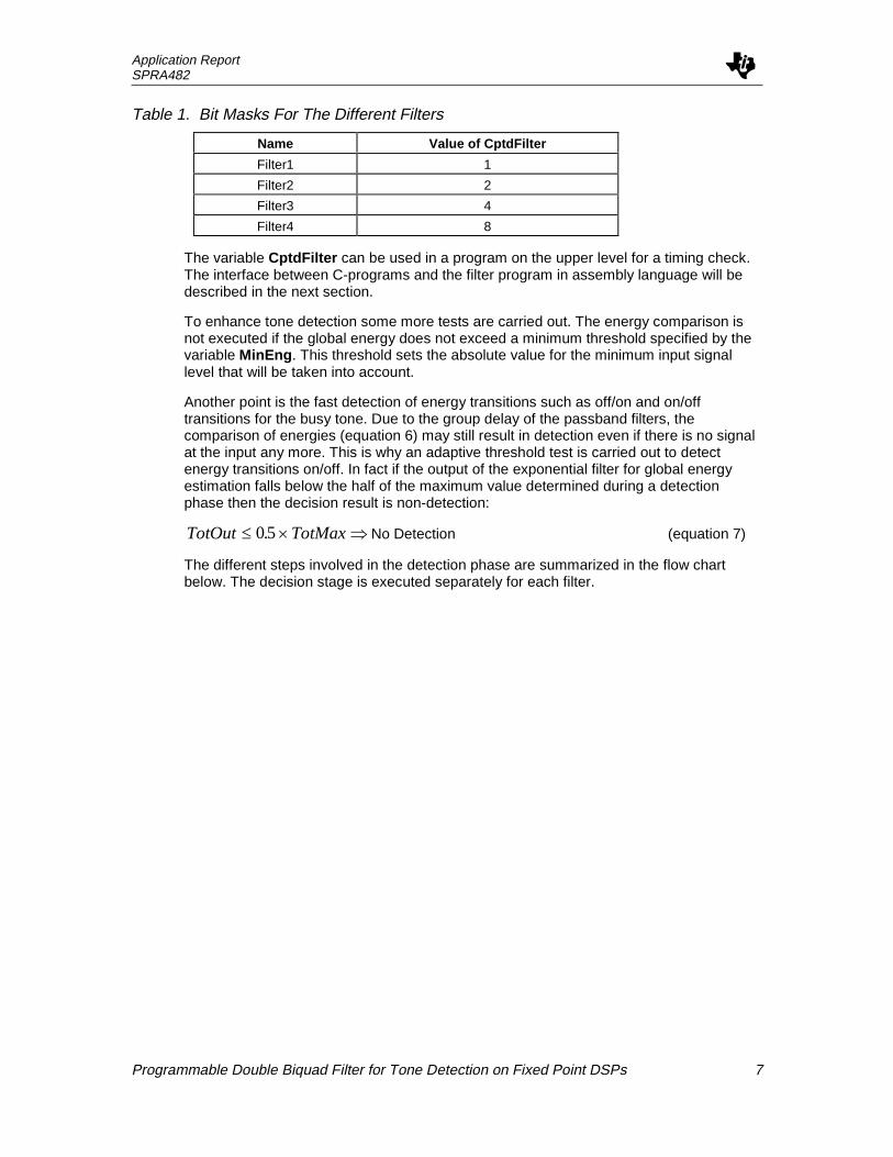
Table 1. Bit Masks For The Different Filters
Name Value of CptdFilter
Filter1 1
Filter2 2
Filter3 4
Filter4 8
The variable CptdFilter can be used in a program on the upper level for a timing check.The interface between C-programs and the filter program in assembly language will bedescribed in the next section.
To enhance tone detection some more tests are carried out. The energy comparison isnot executed if the global energy does not exceed a minimum threshold specified by thevariable MinEng . This threshold sets the absolute value for the minimum input signallevel that will be taken into account.
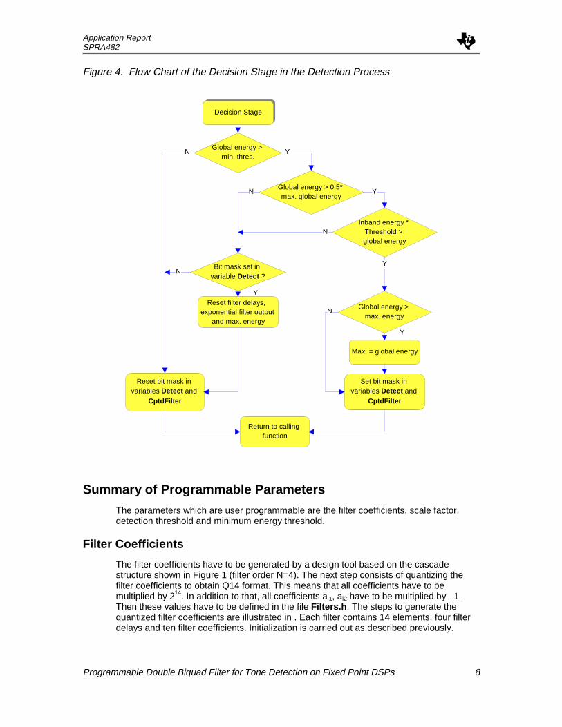
Another point is the fast detection of energy transitions such as off/on and on/offtransitions for the busy tone. Due to the group delay of the passband filters, thecomparison of energies (equation 6) may still result in detection even if there is no signalat the input any more. This is why an adaptive threshold test is carried out to detectenergy transitions on/off. In fact if the output of the exponential filter for global energyestimation falls below the half of the maximum value determined during a detectionphase then the decision result is non-detection:
TotOut TotMax£ ´ Þ05. No Detection (equation 7)
The different steps involved in the detection phase are summarized in the flow chartbelow. The decision stage is executed separately for each filter.
Application ReportSPRA482
Programmable Double Biquad Filter for Tone Detection on Fixed Point DSPs 8
Figure 4. Flow Chart of the Decision Stage in the Detection Process
Decision Stage
Global energy > min. thres.
Global energy > 0.5* max. global energy
Inband energy * Threshold > global energy
Global energy > max. energy
Max. = global energy
Set bit mask in variables Detect and
CptdFilter
Reset bit mask in variables Detect and
CptdFilter
Reset filter delays, exponential filter output
and max. energy
Return to calling function
Bit mask set in variable Detect ?
YN
YN
Y
N
N
Y
Y
N
Summary of Programmable Parameters
The parameters which are user programmable are the filter coefficients, scale factor,detection threshold and minimum energy threshold.
Filter Coefficients
The filter coefficients have to be generated by a design tool based on the cascadestructure shown in Figure 1 (filter order N=4). The next step consists of quantizing thefilter coefficients to obtain Q14 format. This means that all coefficients have to bemultiplied by 214. In addition to that, all coefficients ai1, ai2 have to be multiplied by –1.Then these values have to be defined in the file Filters.h . The steps to generate thequantized filter coefficients are illustrated in . Each filter contains 14 elements, four filterdelays and ten filter coefficients. Initialization is carried out as described previously.
Application ReportSPRA482
Programmable Double Biquad Filter for Tone Detection on Fixed Point DSPs 9
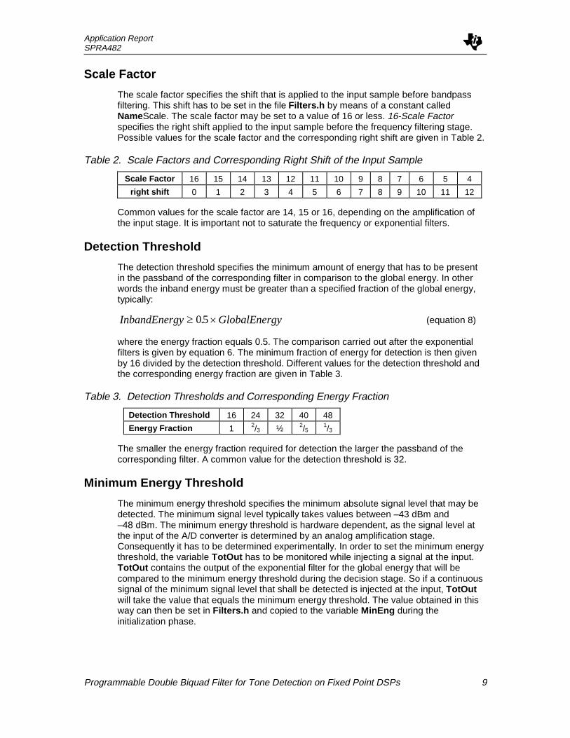
Scale Factor
The scale factor specifies the shift that is applied to the input sample before bandpassfiltering. This shift has to be set in the file Filters.h by means of a constant calledNameScale. The scale factor may be set to a value of 16 or less. 16-Scale Factorspecifies the right shift applied to the input sample before the frequency filtering stage.Possible values for the scale factor and the corresponding right shift are given in Table 2.
Table 2. Scale Factors and Corresponding Right Shift of the Input Sample
Scale Factor 16 15 14 13 12 11 10 9 8 7 6 5 4
right shift 0 1 2 3 4 5 6 7 8 9 10 11 12
Common values for the scale factor are 14, 15 or 16, depending on the amplification ofthe input stage. It is important not to saturate the frequency or exponential filters.
Detection Threshold
The detection threshold specifies the minimum amount of energy that has to be presentin the passband of the corresponding filter in comparison to the global energy. In otherwords the inband energy must be greater than a specified fraction of the global energy,typically:
InbandEnergy GlobalEnergy³ ´05. (equation 8)
where the energy fraction equals 0.5. The comparison carried out after the exponentialfilters is given by equation 6. The minimum fraction of energy for detection is then givenby 16 divided by the detection threshold. Different values for the detection threshold andthe corresponding energy fraction are given in Table 3.
Table 3. Detection Thresholds and Corresponding Energy Fraction
Detection Threshold 16 24 32 40 48
Energy Fraction 1 2/3 ½ 2/51/3
The smaller the energy fraction required for detection the larger the passband of thecorresponding filter. A common value for the detection threshold is 32.
Minimum Energy Threshold
The minimum energy threshold specifies the minimum absolute signal level that may bedetected. The minimum signal level typically takes values between –43 dBm and–48 dBm. The minimum energy threshold is hardware dependent, as the signal level atthe input of the A/D converter is determined by an analog amplification stage.Consequently it has to be determined experimentally. In order to set the minimum energythreshold, the variable TotOut has to be monitored while injecting a signal at the input.TotOut contains the output of the exponential filter for the global energy that will becompared to the minimum energy threshold during the decision stage. So if a continuoussignal of the minimum signal level that shall be detected is injected at the input, TotOutwill take the value that equals the minimum energy threshold. The value obtained in thisway can then be set in Filters.h and copied to the variable MinEng during theinitialization phase.

Application ReportSPRA482
Programmable Double Biquad Filter for Tone Detection on Fixed Point DSPs 10
Interface Between High Level Programs and the FilterProgram
In this section the interface between a C program executing the main task and the filterprogram executed in the sample interrupt will be described.
The detection result of the tone detection procedure can be used by high level applicationS/W in order to carry out a timing check. For this purpose two variables are needed,which have to be referenced as external variables in the C program: CptdFilter andTim0 . CptdFilter contains the bit mask of the corresponding filter in case of detection(Table 3) and zero in case of no detection. Tim0 is a timer that is incremented in thesample interrupt. The maximum value is 7fff hex, which corresponds to 4 seconds at8 kHz.
All filters used in the program have to be initialized with the parameter values specified inthe file Filters.h . This is done by the function Init---() that can be found in the file initFilt.c(where --- stands for the filter name). The routine InitTot() has to be called in order toinitialize the exponential filter for global energy estimation.
An example of a C program which carries out the cadence check of the busy tone isgiven in Figure 5. The program main() calls a function for dialing which may include dialtone detection. After that the routine CadenceCheck is called, which checks thepresence of a tone in the passband of the filter Dial (bit mask set in CptdFilter ) and thencarries out a timing check concerning the on/off sequence of the signal as shown inFigure 5:
Figure 5. Cadence Check for Busy Tone Detection
Busy tone on:Min. and max. timing
Busy tone off:Min. and max. timing
Tolerance concerning the timing is taken into account in the program by the constantvalues BusyMin and BusyMax which correspond to nominal timing –x% and nominaltiming +x%, respectively.
The function CadenceCheck indicates busy tone detection by a return value of 1.

Application ReportSPRA482
Programmable Double Biquad Filter for Tone Detection on Fixed Point DSPs 11
Processor Resources Used By Filter ProgramsTable 4 summarizes the memory occupation (RAM and ROM) as well as computationalload (MIPS) utilized by the filter functions contained in the file biquad.asm .
Table 4. Processor Resources Required for the Tone Detection Module
RAM ROM MIPS
80 words 500 words (biquad.asm)
300 words (initFilt.c)
4.5 (at 9.6 kHz)
3.8 (at 8 kHz)
RAM space is reserved for all filter variables in the file biquad.asm . The sectioncontaining these variables is called Filter . In the linker command file this section has tobe put in a RAM block so as to be contained within one memory page (128 words).
In combination with the V22bis modem on the TMS320C2xx all filters are executed at asampling rate of 8 kHz.
ReferenceDFDP3/plus Digital Filter Design Package Instruction Manual; Atlanta Signal ProcessingInc., 1991
Appendix A. Source Code
FILE: BIQUAD.ASM****************************************** File: BIQUAD.ASM **** **** Author: Katrin Matthes **** **** Description: **** Implementation of programmable **** double biquad filter with **** detection stage (exponential **** filters) ******************************************
NUMFILTER .set 2; example of implementation:; Dial/Busy tone and fax tone detector
.def CPTD
.def TMP
.def _CptdFilter
.ref FromAD,ForDA
.def _TotIn, _TotOut
.def _MinEng
.def _FiltFunc
.def _InitFiltFunc .def _DialShift,_DialIn,_DialOut,_DialThreshold,_DialFilter
.if NUMFILTER >=2
.def _FaxShift,_FaxIn,_FaxOut,_FaxThreshold,_FaxFilter

Application ReportSPRA482
Programmable Double Biquad Filter for Tone Detection on Fixed Point DSPs 12
.elseif NUMFILTER >=3 .def _Filt3Shift,_Filt3In,_Filt3Out,_Filt3Threshold,_Filt3Filter
.elseif NUMFILTER >=4 .def _Filt4Shift,_Filt4In,_Filt4Out,_Filt4Threshold,_Filt4Filter
.endif
.mmregs
;--------------------------------;; BIQUAD; INDEXED; y(n)=B0x(n)+d1(n-1); d1(n)=B1x(n)-A1y(n)+d2(n-1); d2(n)=B2x(n)-A2y(n);; INPUT:; TMP contains scaledinput sample; ARP -> AR1 AR0 -> DNM1; AR1 -> B0 PM=1 (<<1); SSXM; OUTPUT; ARP -> AR1 AR0 -> DNM1; AR1 -> B0; MODIFIED; AR0, AR1;; 42 cycles;----------------------------------; DATA ORGANIZATION:;D1NM1 .BSS ; AR0;D2NM1 .BSS;B0 .BSS ; AR1;B1 .BSS;A1 .BSS;A2 .BSS;B2 .BSSBIQUAD; all filter coefficients Q14;*;* SECOND-ORDER FILTER SECTION;*
ldp #TMPLT TMP ;GET SCALED INPUTMPY *+,ar0 ;P = B0* INPUTlac *+,15,ar1 ;AC= Z-1MPYA *+,ar0 ;AC= Z-1 + (B0* INPUT)
; ;P = B1 * INPUTldp #OutputSACH Output,1 ;Save in OUTPUTLTP Output ;AC= B1 * INPUTADD *-,15,ar1 ;AC= Z-2 + (B1* INPUT)MPY *+ ;P = A1* OUTPUTAPACMPY *+,ar0 ;AC= Z-2 + (B1*INPUT)+(A1*OUTPUT)
; ;P = A2 * OUTPUTSACH *+,1,ar1 ;Save in Z-1Ldp #TMP

Application ReportSPRA482
Programmable Double Biquad Filter for Tone Detection on Fixed Point DSPs 13
LTP TMP ;AC= A2 * OUTPUTMPY *+,ar0 ;P = B2* INPUTAPAC ;AC= (B2 *INPUT)+(A2 * OUTPUT)
SACH *+,1,ar1 ;Save in Z-2
Ldp #Outputlac Outputldp #TMPsacl TMP
LT TMP ;GET SCALED INPUTMPY *+,ar0 ;P = B0* INPUTLac *+,15,ar1 ;AC= Z-1MPYA *+,ar0 ;AC= Z-1 +(B0* INPUT)
; ;P = B1* INPUTldp #OutputSACH Output,1 ;Save in OUTPUTLTP Output ;AC= B1 * INPUTADD *-,15,ar1 ;AC= Z-2 +(B1* INPUT)MPY *+ ;P = A1 * OUTPUTAPACMPY *+,ar0 ;AC= Z-2 +(B1*INPUT)+(A1*OUTPUT)
; ;P = A2 * OUTPUTSACH *+,1,ar1 ;Save in Z-1ldp #TMPLTP TMP ;AC= A2 * OUTPUTMPY *+,ar0 ;P = B2* INPUTAPAC ;AC= (B2 *INPUT) + (A2 * OUTPUT)SACH *+,1,ar1 ;Save in Z-2ret
;------------------;; macro for a filter; 25 cycles;;-----------------Filter .macro Name
.NEWBLOCKldp #_:Name:Shiftlt _:Name:ShiftLDPK #FromADLACT FromAD ;load input sample with specified
;shiftLDPK #TMP
; MULTIPLY INPUT BY GAINSACH TMP
; SET POINTERSLAR AR0,#_:Name:Filterspm 1MAR *,AR0 ; AR0 -> d1(n-1)LARK AR1,#4MAR *,AR1MAR *0+,AR1 ; AR1 -> B0
CALL BIQUAD

Application ReportSPRA482
Programmable Double Biquad Filter for Tone Detection on Fixed Point DSPs 14
ldp #Outputlac Output ; accumulate absolute value
; of 5 input samplesabs
; ldp #_:Name:Inadd _:Name:Insacl _:Name:Insub #MaxValblz $1lac #MaxValsacl _:Name:In
$1.endm
;------------------;; CPTD FILTER; 85 cycles per filter + 40 cycles; = 4 * 85 + 40 (max) = 380;------------------CPTD
SPM 1sovm
; DIAL TONEldp #FromADlac FromAD ; accumulate absolute value
; of 5 input samplesabsldp #_TotInadd _TotInsacl _TotInsub #MaxValblz no_cliplac #MaxValsacl _TotIn
no_clipFilter Dial.if NUMFILTER >= 2Filter Fax.elseif NUMFILTER >= 3Filter Filt4.elseif NUMFILTER >= 4Filter Filt3.endif
ldp #_FiltFunclac _FiltFunccala
rovmret
;-----------------; Inits FiltFunc; called by InitDial();-----------------

Application ReportSPRA482
Programmable Double Biquad Filter for Tone Detection on Fixed Point DSPs 15
_InitFiltFuncldp #_FiltFunclac #TotExpsacl _FiltFunczacsacl TotMaxsacl Detectret
;-----------------------------------------------------; Macro for calculation of the exponential filter based; on the sum of 5 ABS(input sample); Comparison of the global output to the filtered (biquad); output; if (global <=factor * filtered) then DETECTION;; This comparison is not carried out if; 1) the minimum global energy is below the threshold; MinEng; 2) the energy after filtering is below the noise; threshold of the filter; 3) the global energy decreases to 0.5* Max, indicating a; transition on/off;; 40 cycles;-----------------------------------------------------TestOut .macro Name
.newblockldp #_:Name:Outzalr _:Name:Out ; ROUNDINGadd _:Name:In,16-6 ; 1/64SUB _:Name:Out,16-6SACH _:Name:Out
Lac _TotOut ; check min. thres.Sub _MinEngblez $4
lac _TotOut,1 ; TotOut > 0.5*TotMax ?sub TotMax ; detection: ON/OFF transitionblez $3lac _:Name:Out ; noise due to filtersub #:Name:Minblez $4
lac _TotOut,4; Totout<<4- (factor * FilterOut)<<1
lt _:Name:Threshold ; Detection testmpy _:Name:OutspacBLZ $1
; UNDER THRESHOLD$3
lac Detectand #:Name:Maskbz $4lar AR0,#_:Name:Filter

Application ReportSPRA482
Programmable Double Biquad Filter for Tone Detection on Fixed Point DSPs 16
mar *,ar0zacsacl *+ ; clear D11(N-1)sacl *+ ; clear D12(N-1)sacl *+ ; clear D21(N-1)sacl * ; clear D22(N-1)sacl _:Name:Outsacl TotMax
$4LALK #~:Name:Maskand Detectsacl Detectldp #_CptdFilterAND _CptdFilterB $2
; OVER THRESHOLD$1
lac _TotOutsub TotMaxblez $5lac _TotOut ; look for maximumsacl TotMax
$5LALK #:Name:Maskor Detectsacl DetectOR _CptdFilter
$2SACL _CptdFilterzacsacl _:Name:In
.endm
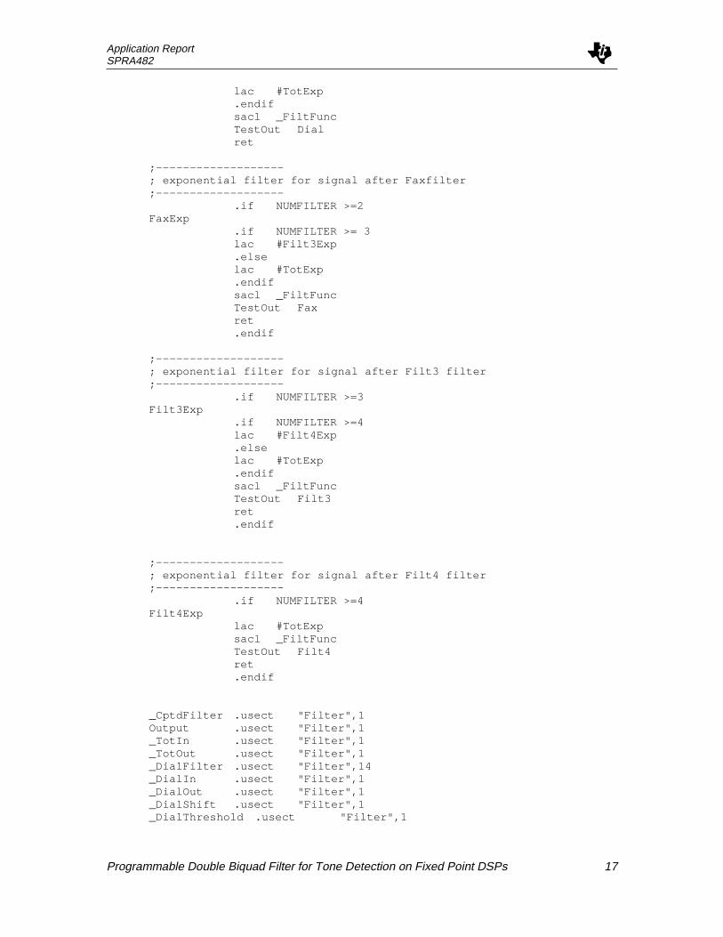
;-------------------; exponential filter for global signal;-------------------TotExp
lac #DialExpsacl _FiltFunczalr _TotOut ; ROUNDINGldp #_TotInadd _TotIn,16-6 ; 1/64LDPK #_TotOutSUB _TotOut,16-6SACH _TotOutLdp #_TotInzacsacl _TotInret
;-------------------; exponential filter for signal after Dialfilter;-------------------DialExp
.if NUMFILTER >= 2lac #FaxExp.else
Application ReportSPRA482
Programmable Double Biquad Filter for Tone Detection on Fixed Point DSPs 17
lac #TotExp.endifsacl _FiltFuncTestOut Dialret
;-------------------; exponential filter for signal after Faxfilter;-------------------
.if NUMFILTER >=2FaxExp
.if NUMFILTER >= 3lac #Filt3Exp.elselac #TotExp.endifsacl _FiltFuncTestOut Faxret.endif
;-------------------; exponential filter for signal after Filt3 filter;-------------------
.if NUMFILTER >=3Filt3Exp
.if NUMFILTER >=4lac #Filt4Exp.elselac #TotExp.endifsacl _FiltFuncTestOut Filt3ret.endif
;-------------------; exponential filter for signal after Filt4 filter;-------------------
.if NUMFILTER >=4Filt4Exp
lac #TotExpsacl _FiltFuncTestOut Filt4ret.endif
_CptdFilter .usect "Filter",1Output .usect "Filter",1_TotIn .usect "Filter",1_TotOut .usect "Filter",1_DialFilter .usect "Filter",14_DialIn .usect "Filter",1_DialOut .usect "Filter",1_DialShift .usect "Filter",1_DialThreshold .usect "Filter",1

Application ReportSPRA482
Programmable Double Biquad Filter for Tone Detection on Fixed Point DSPs 18
.if NUMFILTER >=2_FaxFilter .usect "Filter",14_FaxIn .usect "Filter",1_FaxOut .usect "Filter",1_FaxShift .usect "Filter",1_FaxThreshold .usect "Filter",1
.elseif NUMFILTER >=3_Filt3Filter .usect "Filter",14_Filt3In .usect "Filter",1_Filt3Out .usect "Filter",1_Filt3Shift .usect "Filter",1_Filt3Threshold .usect "Filter",1
.elseif NUMFILTER >=4_Filt4Filter .usect "Filter",14_Filt4In .usect "Filter",1_Filt4Out .usect "Filter",1_Filt4Shift .usect "Filter",1_Filt4Threshold .usect "Filter",1
.endif_MinEng .usect "Filter",1_FiltFunc .usect "Filter",1Detect .usect "Filter",1TotMax .usect "Filter",1TMP .usect "Filter",1
MaxVal .set 7fffhDialMin .set 90hFaxMin .set 5ahFilt3Min .set 55hFilt4Min .set 55hDialMask .set 0001hFaxMask .set 0002hFilt3Mask .set 0004hFilt4Mask .set 0008h
FILE: INITFILT.C/*********************************************************//* File: INITFILT.C *//* *//* Author: Katrin Matthes *//* *//*Routine initializes all CPTD Filters for double biquad *//* Memory Organization: *//* NameFilter: *//* D11(N-1) *//* D12(N-1) *//* D21(N-1) *//* D22(N-1) *//* B10 *//* B11 *//* A11 *//* A12 *//* B12 *//* B20 *//* B21 */

Application ReportSPRA482
Programmable Double Biquad Filter for Tone Detection on Fixed Point DSPs 19
/* B22 *//* A21 *//* A22 *//*********************************************************/
#include "Filters.h"
extern int DialFilter[14];extern int DialThreshold;extern int DialIn, DialOut, TotIn, TotOut, DialShift;#if NUMFILTER >=2extern int FaxFilter[14];extern int FaxThreshold;extern int FaxIn, FaxOut, FaxShift;#elif NUMFILTER >=3extern int Filt3Filter[14];extern int Filt3Threshold;extern int Filt3In, Filt3Out, Filt3Shift;#elif NUMFILTER >=4extern int Filt4Filter[14];extern int Filt4Threshold;extern int Filt4In, Filt4Out, Filt4Shift;#endif
extern int MinEng;int InitFiltFunc(void);
void InitTot(void){
MinEng=MinThres;TotIn=0;TotOut=0;InitFiltFunc();
}
void InitDial(void){
DialFilter[0]=0;DialFilter[1]=0;DialFilter[2]=0;DialFilter[3]=0;DialFilter[4]=Dial1_B0;DialFilter[5]=Dial1_B1;DialFilter[6]=Dial1_A1;DialFilter[7]=Dial1_A2;DialFilter[8]=Dial1_B2;DialFilter[9]=Dial2_B0;DialFilter[10]=Dial2_B1;DialFilter[11]=Dial2_A1;DialFilter[12]=Dial2_A2;DialFilter[13]=Dial2_B2;
DialThreshold=DialThres;DialIn=0;DialOut=0;DialShift=DialScale;

Application ReportSPRA482
Programmable Double Biquad Filter for Tone Detection on Fixed Point DSPs 20
}
#if NUMFILTER >= 2
void InitFax (void){
FaxFilter[0]=0;FaxFilter[1]=0;FaxFilter[2]=0;FaxFilter[3]=0;FaxFilter[4]=Fax1_B0;FaxFilter[5]=Fax1_B1;FaxFilter[6]=Fax1_A1;FaxFilter[7]=Fax1_A2;FaxFilter[8]=Fax1_B2;FaxFilter[9]=Fax2_B0;FaxFilter[10]=Fax2_B1;FaxFilter[11]=Fax2_A1;FaxFilter[12]=Fax2_A2;FaxFilter[13]=Fax2_B2;
FaxThreshold=FaxThres;FaxIn=0;FaxOut=0;FaxShift=FaxScale;
}
#elif NUMFILTER >= 3
void InitFilt3 (void){
Filt3Filter[0]=0;Filt3Filter[1]=0;Filt3Filter[2]=0;Filt3Filter[3]=0;Filt3Filter[4]=Filt3_1_B0;Filt3Filter[5]=Filt3_1_B1;Filt3Filter[6]=Filt3_1_A1;Filt3Filter[7]=Filt3_1_A2;Filt3Filter[8]=Filt3_1_B2;Filt3Filter[9]=Filt3_2_B0;Filt3Filter[10]=Filt3_2_B1;Filt3Filter[11]=Filt3_2_A1;Filt3Filter[12]=Filt3_2_A2;Filt3Filter[13]=Filt3_2_B2;
Filt3Threshold=Filt3Thres;Filt3In=0;Filt3Out=0;Filt3Shift=Filt3Scale;
}
#elif NUMFILTER >= 4
void InitFilt4 (void){
Filt4Filter[0]=0;Filt4Filter[1]=0;

Application ReportSPRA482
Programmable Double Biquad Filter for Tone Detection on Fixed Point DSPs 21
Filt4Filter[2]=0;Filt4Filter[3]=0;Filt4Filter[4]=Filt4_1_B0;Filt4Filter[5]=Filt4_1_B1;Filt4Filter[6]=Filt4_1_A1;Filt4Filter[7]=Filt4_1_A2;Filt4Filter[8]=Filt4_1_B2;Filt4Filter[9]=Filt4_2_B0;Filt4Filter[10]=Filt4_2_B1;Filt4Filter[11]=Filt4_2_A1;Filt4Filter[12]=Filt4_2_A2;Filt4Filter[13]=Filt4_2_B2;
Filt4Threshold=Filt4Thres;Filt4In=0;Filt4Out=0;Filt4Shift=Filt4Scale;
}
#endif
FILE: FILTERS.H/*************************************//* File: FILTERS.H *//* Author: Katrin Matthes *//* *//* Include file containing *//* filter coefficients for *//* double biquad filters *//*************************************/
#define NUMFILTER 2/* define number of filters executed in parallel */
/* Dial Filter*//* All coefficients Q14 *//* Coefficients for 1st biquad */#define Dial1_B0 539#define Dial1_B1 -914#define Dial1_B2 539#define Dial1_A1 30507#define Dial1_A2 -16092/* Coefficients for 2nd biquad */#define Dial2_B0 4602#define Dial2_B1 -9029#define Dial2_B2 4602#define Dial2_A1 30881#define Dial2_A2 16118
#define DialScale 15 /*input sample >> 1*/
/* threshold for dial tone detection */#define DialThres 0x28 /* 0x31 */
/* Fax Filter 1100 Hz */

Application ReportSPRA482
Programmable Double Biquad Filter for Tone Detection on Fixed Point DSPs 22
/* Coefficients for 1st biquad */#define Fax1_B0 1209#define Fax1_B1 -999#define Fax1_B2 1209#define Fax1_A1 20049#define Fax1_A2 -15773/* Coefficients for 2nd biquad */#define Fax2_B0 4616#define Fax2_B1 -7426#define Fax2_B2 4616#define Fax2_A1 21726#define Fax2_A2 -15806
#define FaxScale 15 /* input sample >>1 */
/* threshold for answer tone detection */#define FaxThres 0x25 /*0x2a*/
/* Filt3 Filter xxx Hz *//* Coefficients for 1st biquad */#define Filt3_1_B0 0#define Filt3_1_B1 0#define Filt3_1_B2 0#define Filt3_1_A1 0#define Filt3_1_A2 0/* Coefficients for 2nd biquad */#define Filt3_2_B0 0#define Filt3_2_B1 0#define Filt3_2_B2 0#define Filt3_2_A1 0#define Filt3_2_A2 0
#define Filt3Scale 15 /* input sample >>1 */
/* threshold for Filt3 detection */#define Filt3Thres 0x18 /*0x38*/
/* Filt4 Filter xxx Hz *//* Coefficients for 1st biquad */#define Filt4_1_B0 0#define Filt4_1_B1 0#define Filt4_1_B2 0#define Filt4_1_A1 0#define Filt4_1_A2 0/* Coefficients for 2nd biquad */#define Filt4_2_B0 0#define Filt4_2_B1 0#define Filt4_2_B2 0#define Filt4_2_A1 0#define Filt4_2_A2 0
#define Filt4Scale 15 /* input sample >>1 */
/* threshold for Filt4 detection */#define Filt4Thres 0x20 /*0x38*/

Application ReportSPRA482
Programmable Double Biquad Filter for Tone Detection on Fixed Point DSPs 23
#define MinThres 0x110/* minimum detection threshold */
/* min. and max. timing for cadence check: busy tone */#define BusyMin 42 /* value * 10ms, BusyMax+20ms to account for filter delay*/#define BusyMax 57
/* Masks for the different Filters*/#define DialMask 0x0001#define FaxMask 0x0002#define Filt3Mask 0x0004#define Filt4Mask 0x0008
/* initialization routines for the implemented filters */void InitTot(void);void InitDial(void);#if NUMFILTER >=2void InitFax(void);#elif NUMFILTER >=3void InitFilt3(void);#elif NUMFILTER >=4void InitFilt4(void);#endif
Appendix B. GlossaryCPTD Call Progress Tone Detection
IIR Infinite Impulse Response
Application ReportSPRA482
Programmable Double Biquad Filter for Tone Detection on Fixed Point DSPs 24
TI Contact Numbers
INTERNET
TI Semiconductor Home Pagewww.ti.com/sc
TI Distributorswww.ti.com/sc/docs/distmenu.htm
PRODUCT INFORMATION CENTERS
AmericasPhone +1(972) 644-5580Fax +1(972) 480-7800Email [email protected]
Europe, Middle East, and AfricaPhone
Deutsch +49-(0) 8161 80 3311English +44-(0) 1604 66 3399Español +34-(0) 90 23 54 0 28Francais +33-(0) 1-30 70 11 64Italiano +33-(0) 1-30 70 11 67
Fax +44-(0) 1604 66 33 34Email [email protected]
International +81-3-3457-0972Domestic 0120-81-0026
FaxInternational +81-3-3457-1259Domestic 0120-81-0036
Email [email protected]
AsiaPhone
International +886-2-23786800Domestic
Australia 1-800-881-011TI Number -800-800-1450
China 10810TI Number -800-800-1450
Hong Kong 800-96-1111TI Number -800-800-1450
India 000-117TI Number -800-800-1450
Indonesia 001-801-10TI Number -800-800-1450
Korea 080-551-2804Malaysia 1-800-800-011
TI Number -800-800-1450New Zealand 000-911
TI Number -800-800-1450Philippines 105-11
TI Number -800-800-1450Singapore 800-0111-111
TI Number -800-800-1450Taiwan 080-006800Thailand 0019-991-1111
TI Number -800-800-1450Fax 886-2-2378-6808Email [email protected]
TI is a trademark of Texas Instruments Incorporated.
Other brands and names are the property of their respective owners.

Application ReportSPRA482
Programmable Double Biquad Filter for Tone Detection on Fixed Point DSPs 25
IMPORTANT NOTICE
Texas Instruments and its subsidiaries (TI) reserve the right to make changes to theirproducts or to discontinue any product or service without notice, and advise customers toobtain the latest version of relevant information to verify, before placing orders, thatinformation being relied on is current and complete. All products are sold subject to theterms and conditions of sale supplied at the time of order acknowledgement, includingthose pertaining to warranty, patent infringement, and limitation of liability.
TI warrants performance of its semiconductor products to the specifications applicable atthe time of sale in accordance with TI's standard warranty. Testing and other qualitycontrol techniques are utilized to the extent TI deems necessary to support this warranty.Specific testing of all parameters of each device is not necessarily performed, exceptthose mandated by government requirements.
CERTAIN APPLICATIONS USING SEMICONDUCTOR PRODUCTS MAY INVOLVEPOTENTIAL RISKS OF DEATH, PERSONAL INJURY, OR SEVERE PROPERTY ORENVIRONMENTAL DAMAGE (“CRITICAL APPLICATIONS"). TI SEMICONDUCTORPRODUCTS ARE NOT DESIGNED, AUTHORIZED, OR WARRANTED TO BESUITABLE FOR USE IN LIFE-SUPPORT DEVICES OR SYSTEMS OR OTHERCRITICAL APPLICATIONS. INCLUSION OF TI PRODUCTS IN SUCH APPLICATIONSIS UNDERSTOOD TO BE FULLY AT THE CUSTOMER'S RISK.
In order to minimize risks associated with the customer's applications, adequate designand operating safeguards must be provided by the customer to minimize inherent orprocedural hazards.
TI assumes no liability for applications assistance or customer product design. TI doesnot warrant or represent that any license, either express or implied, is granted under anypatent right, copyright, mask work right, or other intellectual property right of TI coveringor relating to any combination, machine, or process in which such semiconductorproducts or services might be or are used. TI's publication of information regarding anythird party's products or services does not constitute TI's approval, warranty, orendorsement thereof.
Copyright Ó 1999 Texas Instruments Incorporated