doosan retrofit servicemariness.co.kr/02_business/doosan retrofit service.pdfengine hours) 0.05 /...
TRANSCRIPT

Part Sales & Technical Service Team
DOOSAN RETROFIT SERVICE
Rev. 7
1
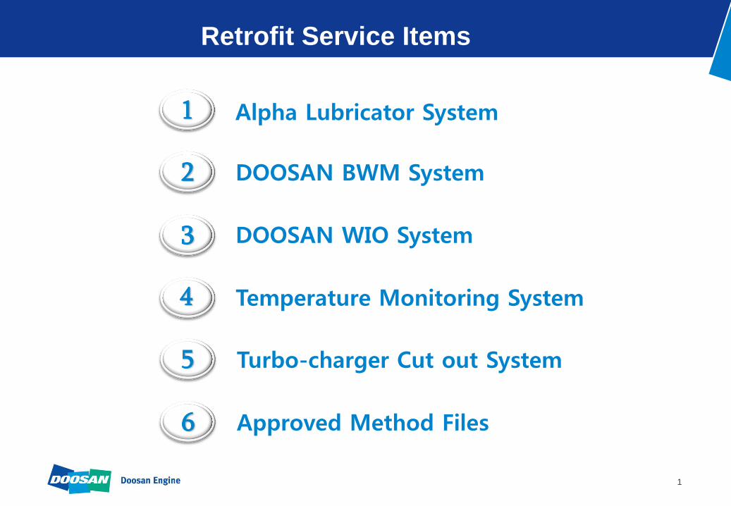
Retrofit Service Items
Alpha Lubricator System 1
DOOSAN BWM System 2
DOOSAN WIO System 3
Temperature Monitoring System 4
Turbo-charger Cut out System 5
Approved Method Files 6

2
ADAPTIVE CYLINDER OIL CONTROL SYSTEM
The Ultimate Lubrication System

3
Contents
1. What is Alpha Lubricator ?
2. Layout
3. Main components
4. How to retrofit ?
5. Benefits of Alpha Lubricator
6. Reference list

4
1. What is Alpha Lubricator ?
High pressure injection directly into the piston ring pack
Very Precise Injection Timing ( Electronically )
Optimal Utilization of the Oil with minimum of loss
Pre-lubrication of the cylinder before start of the engine
Very Easy and Precise control of the feed rate

5
1. What is Alpha Lubricator ?
Description Mechanical Type Alpha Lubricator
Feed Rate 1.2 g/kwh (K/L)
1.5 g/kwh (S) S % x 0.26 g/kwh
Oil Consumption RPM dependent LOAD dependent
Adjustment of Feed Rate Pump Stroke
(Adjusting Bolt)
Injection Frequency
(in HMI)
Pump Stroke Adjustable Fixed
Injection Frequency 1 / 1 revolution ( fixed ) Adjustable
Injection Pump Pressure 4 – 5 bar 40 – 50 bar
Oil Actuating Power Camshaft Rotation Booster Oil Pressure
Operating Method Mechanic Electronic
Mechanical Type VS Alpha Lubricator

6
2. Layout
1)System layout
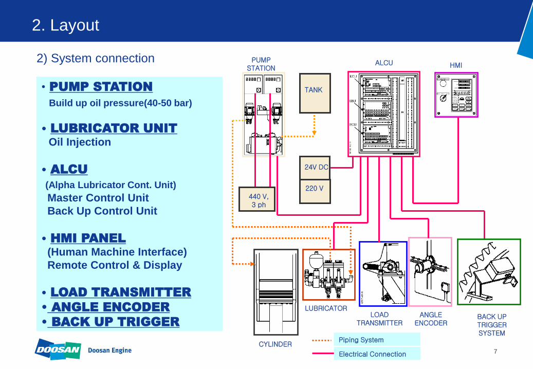
7
2. Layout
2) System connection
PUMP STATION
ALCU
• PUMP STATION
Build up oil pressure(40-50 bar)
• LUBRICATOR UNIT
Oil Injection
• ALCU
(Alpha Lubricator Cont. Unit)
Master Control Unit
Back Up Control Unit
• HMI PANEL
(Human Machine Interface)
Remote Control & Display
• LOAD TRANSMITTER
• ANGLE ENCODER
• BACK UP TRIGGER
TANK
HMI
CYLINDER
LUBRICATOR LOAD
TRANSMITTER ANGLE
ENCODER BACK UP TRIGGER SYSTEM
24V DC
440 V, 3 ph
220 V
Electrical Connection
Piping System
8
3. Main components
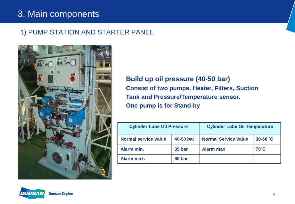
1) PUMP STATION AND STARTER PANEL
Build up oil pressure (40-50 bar)
Consist of two pumps, Heater, Filters, Suction
Tank and Pressure/Temperature sensor.
One pump is for Stand-by
Cylinder Lube Oil Pressure Cylinder Lube Oil Temperature
Normal service Value 40-50 bar Normal Service Value 30-60 ˚C
Alarm min. 35 bar Alarm max 70˚C
Alarm max. 60 bar

9
3. Main components
2) LUBRICATOR UNITS
Oil Injection
- One Lubricator for below 60 bore Engines, Two Lubricators for 70 – 98 bore
Engines
- Consist of inlet nitrogen accumulator ( 25-30 bar ) and outlet
accumulator (1.5bar )

10
3. Main components
3) ALCU & LOAD TRANSMITTER
ALCU - Master Control Unit (MCU) - Switch Board Unit (SBU)
- Backup Control Unit (BCU)
LOAD TRANSMITTER - Calibration with Engine load - FUEL INDEX MCU
11
3. Main components
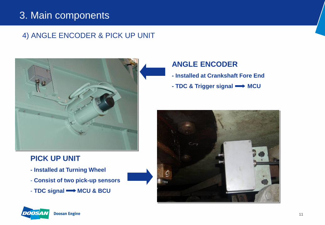
4) ANGLE ENCODER & PICK UP UNIT
ANGLE ENCODER
- Installed at Crankshaft Fore End
- TDC & Trigger signal MCU
PICK UP UNIT
- Installed at Turning Wheel
- Consist of two pick-up sensors
- TDC signal MCU & BCU

12
3. Main components
5) HMI & UPS PANEL
Control & Display Interface - Adjustment of Feed Rate
- Display of Engine Speed,
Fuel Index, Oil Pressure,
Oil Temperature and Alarm
UPS Panel
- Uninterruptible Power
Supply for Alpha System

13
4. How to retrofit ?
MODIFICATION PARTS FOR ALPHA
1) CYLINDER LINER
※ in case of previous design
- Drilling of Oil Hole ( Φ 4 -> Φ 9 )
- Grinding Oil Groove
2) NON RETURN VALVE - Adoption of New Non Return Valve

14
4. How to retrofit ?
1) CYLINDER LINER
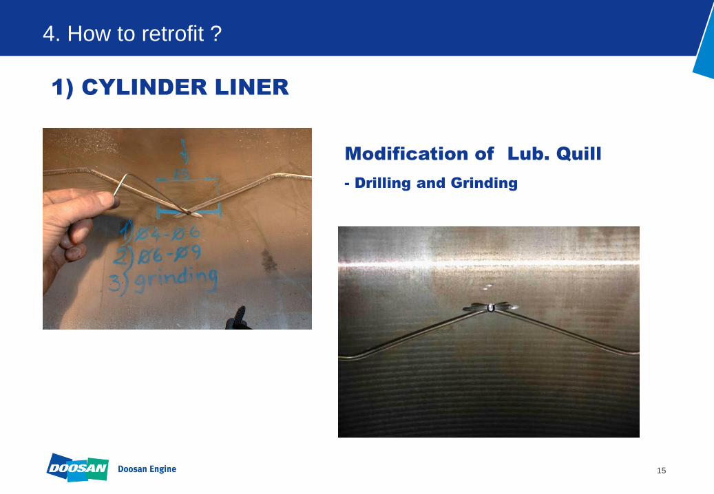
15
4. How to retrofit ?
1) CYLINDER LINER
Modification of Lub. Quill
- Drilling and Grinding

16
4. How to retrofit ?
2) NON RETURN VALVE

17
4. How to retrofit ?
MODIFICATION TIME CHART
1 2 3 4 5 6 7
Cyl. Cover Dismounting & Assembly
Cyl. Liner Modified Lub. Oil Pocket
Booster Pump Unit
Piping & Lub. Unit
Control Unit
HMI Panel
Angle Encoder
Back up Trigger
Flushing & Cleaning
Supervision Commisioning of System
REMARK 8 WORKING PEOPLE
Replaced Non-return Valve
Electric Cabling
Installation of
Alpha
Component
PROCEDUREWORKING DAY

18
5. Benefits of Alpha Lubricator
1) Saving Cost
6S50MC-C 7S60MC 7S80MC 12K90MC
Kw 9,488 14,313 25,485 54,898
BHP 12,900 19,460 34,650 74,640
Kw 8,065 12,166 21,662 46,663
BHP 10,965 16,541 29,453 63,444
% 3.00 3.00 3.00 3.00
g/Kwh 1.50 1.50 1.50 1.20
g/BHPh 1.10 1.10 1.10 0.90
g/Kwh 0.78 0.78 0.78 0.78
g/BHPh 0.57 0.57 0.57 0.57
Hour 7,500 7,500 7,500 7,500
$/ton 1,700 1,700 1,700 1,700
$/year 74,096 111,776 199,025 266,941
Cylinder Lub. Oil price
Saving for Year
Running Hours/Year
Fuel oil sulphur content
Alpha with ACC
Specification
Layout SMCR
Load point (=85% SMCR)
Mech. Lubricator
Feed rate

19
5. Benefits of Alpha Lubricator
2) Cylinder Liner Condition
ENGINE : DOOSAN-MAN B&W 12K90MC OWNER : A.P.MOLLER
DEL. DATE : 2000.09.25
TEST DATE : 2001.12.08 ( at 8390 Running Hour )
12K90MC, 3th April 2002 at
10,543 engine hours and
2153 operating hours at
Alpha ACC = S% * 0.25 g/bhph
20
899,80
900,00
900,20
900,40
900,60
900,80
901,00
901,20
901,40
0 5000 10000 15000 20000 25000
Engine Hours
Max L
iner
Dia
mete
r (m
m)
0.05 / 1000 Hours (mm) Cyl No. 1A Cyl No. 2A Cyl No. 3A
Cyl No. 4A Cyl No. 6A Cyl No. 8A Cyl No. 9A
Cyl No. 1A Cyl No. 9A Cyl No. 10A Cyl No. 1A
Cyl No. 6A Cyl No. 7A Cyl No. 10A Cyl No. 12A
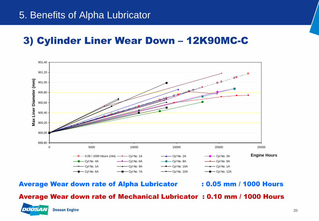
5. Benefits of Alpha Lubricator
3) Cylinder Liner Wear Down – 12K90MC-C
Average Wear down rate of Alpha Lubricator : 0.05 mm / 1000 Hours
Average Wear down rate of Mechanical Lubricator : 0.10 mm / 1000 Hours

21
6. Reference List
As of MARCH 2010
ENG.TYPE
RETROFIT WORK
(INCLUDING
MATERIAL)
MATERIAL SUPPLY
TOTAL
46MC/MC-C 3 3
50MC/MC-C 44 16 60
60MC/MC-C 22 19 41
70MC/MC-C 15 15
80MC/MC-C 13 13
90MC/MC-C 16 16
98MC/MC-C 3 3
TOTAL 116 35 151
Reference List of Alpha for Doosan Engine

22
BEARING WARNING AND CONTROL SYSTEM
An Ultimate Solution for the Bearing Safety

23
Contents
1. What is BWACS ?
2. Layout
3. Main components
4. System function
5. Specification
6. How to retrofit ?

24
1. What is BWACS ?
1) Introduction
BWACS, which is a BWM (Bearing Wear Monitoring) System, is specially developed
by Doosan as a engine builder and fully approved by MAN Diesel and classes.
MAN Diesel have adopted Bearing Wear Monitoring (BWM) system as standard
equipment for new vessel contracts signed after 1st March 2008.
By introducing BWACS, severe bearing damage resulting in consequential damage
to the crankshaft, bedplate and crossheads can be avoided, and long and costly
repair time can be minimised.
When installed, open-up inspections on a routine basis can be omitted or decreased
in frequency.

25
1. What is BWACS ?
1) Introduction
Open-up inspection is a main fact of bearing damage.
Bearing damages
Solution !

26
1. What is BWACS ?
2) Working principle
The principle of BWACS is to measure the change of BDC (Bottom Dead Center) level
relative to engine structure.
Measure how far the crosshead guide shoe comes down at BDC position of each cylinder.
Crosshead bearing
Crankpin bearing
Main bearing
Key Features
High accurate system of 10ųm degrees.
Simple and compact components.
User-friendly monitoring program.

27
2. Layout
1)System configuration
Main units for BWACS
SCU (Signal Capture Unit)
SAU (Signal Analysis Unit)
DMU (Data Monitoring Unit)
UPS
Power supply
SCU is consisted of two proximity sensors, a temperature sensor and a control module.
It can measure bearing wear value and send the measured data to SAU.
SAU analyzes the measured data and then send the analyzed data to DMU shows
operators the result of wear value and wear trend.
DMU displays real time wear value and trend graph.
UPS and Power supply unit supply the electric power to SCU, SAU and DMU.

28
2. Layout
2) System configuration diagram
: Signal Flow
: Power Flow
Inside of Engine
Inside of Console at ECR SAU UPS Power supply
DMU
SCU SCU SCU
….. SCU
Mount of Console at ECR

29
2. Layout
3) Mechanical installation diagram
ENGINE OUTSIDE
ENGINE INSIDE
ENGINE CONTROL ROOM
220V AC
POWER SUPPLY UPS SAU
DMU
SCU
To AMS
JUNCTION
BOX
Cable Gland
Guide shoe
1 2 3 4 5 6
Engine Wall
RS485 Cable
Power Cable RS485 Cable
24V DC
Power Supply & Communication Line

30
2. Layout
4) System connection diagram
31
3. Main components
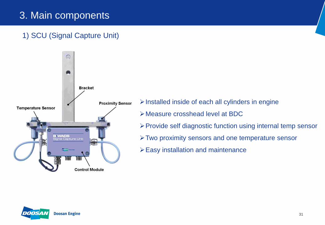
1) SCU (Signal Capture Unit)
Installed inside of each all cylinders in engine
Measure crosshead level at BDC
Provide self diagnostic function using internal temp sensor
Two proximity sensors and one temperature sensor
Easy installation and maintenance

32
3. Main components
2) SAU (Signal Analysis Unit)
3) DMU (Data Monitoring Unit)
Installed inside console of ECR (Engine Control Room)
Communicate with SCUs to analyze the measured data
Provide an early bearing warning, alarm and slowdown
Possible to connect up to 20 SCUs by one unit
Mounted in ECR console
Real time monitoring
Display wear trend and system status
Touch screen PC with UPS

33
4. System function
1) Wear value and deviation monitoring
B-WACS shows the Filtered wear value from two sensors of all cylinders in real time
wear values are displayed as graphs.
Sensor Deviation shows designated the difference between the individual sensor and the
average of all sensors.
34
4. System function
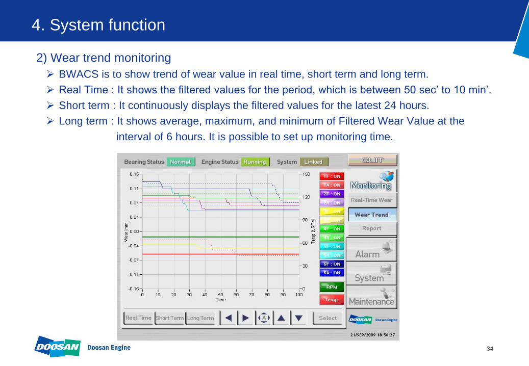
2) Wear trend monitoring
BWACS is to show trend of wear value in real time, short term and long term.
Real Time : It shows the filtered values for the period, which is between 50 sec’ to 10 min’.
Short term : It continuously displays the filtered values for the latest 24 hours.
Long term : It shows average, maximum, and minimum of Filtered Wear Value at the
interval of 6 hours. It is possible to set up monitoring time.

35
4. System function
3) Alarm list
Alarm list contains all Alarms happening
after the start of the B-WACS system.
±0.25 mm Pre warning limit, sensor deviation
±0.5 mm Slow down limit, sensor deviation
±0.7 mm Slow down limit, filtered sensor value
±0.3 mm Alarm limit. cylinder deviation
±0.4 mm Alarm limit, sensor deviation
±0.5 mm Alarm limit, filtered sensor value
Wear Value Description
4) Alarm limits
Standard alarm limits presented by MAN Diesel.
The limits are changeable as needed.

36
5. Specification
1.SCU
1) Proximity Sensor
- Input Voltage : 10 - 30V DC
- Current Consumption : 4 - 20 mA
- Sensing Range : 1 - 7 mm
- Accuracy : ± 10
- Housing Material : Chrome-plated brass
- Operating Temperature : 25 - 70
2) Control module
- Input Voltage : 15 V to 34 V DC
- Current Consumption @24V : 150mA average
- Operating Temperature : -20 top 70
2.SAU
- Input Voltage : 15 V to 34 V dc
- Current Consumption @24V : 150mA average
- Internal Nonvolatile Memory : 16GBytes
- Operating Temperature : -20 top 70
3.DMU
- Input Voltage : DC 24V +15%/-20%
- Power Consumption : 30W
- Touch Screen : Analogue Resistive 8.4”, 800 x 600
- IP Rating : IP60
- Vibration : 0.7g
- Operating Temperature : 0˚C to + 60˚C / 32˚F to 140˚F
4.UPS
- Input Voltage : 24VDC
- Output Voltage : 24VDC
- Power : 1150VA/770Watt
- Interface : USB, Serial Port
5. Power supply
- Input Voltage : 100 – 240VAC
- Input fuse : 6.3A
- Input frequency : 45 – 65 Hz
- Output Voltage : 24VDC

37
6. How to retrofit?
1) Installation of SM (Sensing Module)
SCU
38
6. How to retrofit?
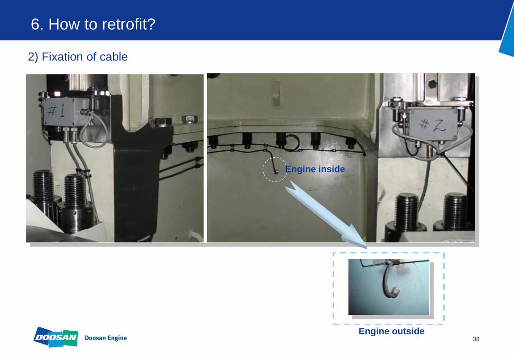
2) Fixation of cable
Engine inside
Engine outside

39
6. How to retrofit?
3) Tuning of gap between sensor and crosshead
4mm shim for tuning
4) Installation of SAU
5) Installation of DMU

40
6. How to retrofit?
Engine side
ECR
Junction Box
#1 #2 #3 #5 #4
Crosshead
Liner
DMU
SAU
SCU

41
MODIFICATION TIME CHART
1 2 3 4 5 6
Signal Capture Unit
UPS & Power Supply
Signal Analysis Unit
Data Monitoring Unit
Cleaning
Supervision Commisioning of System
REMARK 5 WORKING PEOPLE
Retrofit Schedule for BWM System ( Below 8 cyl')
Electric Cabling
Installation of
BWM
Component
PROCEDUREWORKING DAY
6. How to retrofit?

42
MODIFICATION TIME CHART
1 2 3 4 5 6
Signal Capture Unit
UPS & Power Supply
Signal Analysis Unit
Data Monitoring Unit
Cleaning
Supervision Commisioning of System
REMARK 7 WORKING PEOPLE
Retrofit Schedule for BWM System ( Over 9 cyl')
Electric Cabling
Installation of
BWM
Component
PROCEDUREWORKING DAY
6. How to retrofit?

43
OIL WARNING AND CONTROL SYSTEM
The Best Solution for Water in Oil Monitoring

44
Contents
1.What is OWACS ?
2.Layout
3.Main components
5.Specification
6.How to retrofit ?
7.Scope of supply
4.System function

45
1. What is OWACS ?
1) Background
Water in oil is a major contributor to a poor bearing
condition, and worst for crosshead bearings having
a lead-based overlayer featuring a nickel interlayer.
The rapid wear from corrosion due to water in
lubricating oil can lead to scuffing between the pin
and the nickel-interlayer, which can lead to steel to
steel contact in a matter of hours.
These problems can be prevented by OWACS.
Bearing Metal Worn Out
46
1. What is OWACS ?
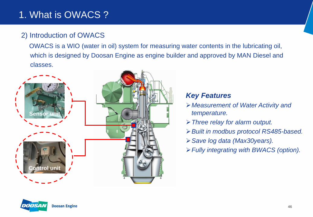
2) Introduction of OWACS
OWACS is a WIO (water in oil) system for measuring water contents in the lubricating oil,
which is designed by Doosan Engine as engine builder and approved by MAN Diesel and
classes.
Control unit
Sensor unit
Key Features
Measurement of Water Activity and
temperature.
Three relay for alarm output.
Built in modbus protocol RS485-based.
Save log data (Max30years).
Fully integrating with BWACS (option).
47
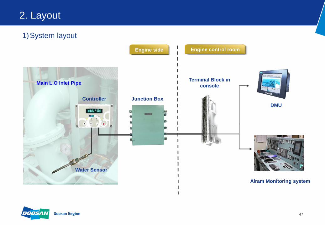
2. Layout
1)System layout
DMU
Main L.O Inlet Pipe
Water Sensor
Junction Box Controller
Terminal Block in
console
Alram Monitoring system
Engine side Engine control room

48
2. Layout
2) System interconnection
DMU
Terminal Block Controller Box
Ship’s
Alarm
Monitoring
System
RS485
Twisted pair
screened
Junction Box
Sensor
Multicore
12 twisted
pair screened
Main L.O Inlet Pipe
Multicore
12 twisted
pair screened
Multicore
6 twisted
pair screened
1X1
screened per
sensor
Engine side Engine control room

49
3. Main components
1) Sensor unit
Sensor unit is attached at main inlet pipe and measures
water content in lubricating oil by humidity sensor.
High accuracy (including nonlinearity, 0.02[aw])
Maximum Operating Pressure: 10bar
Housing: Stainless Steel
2) Control unit
Installed on engine for analysing of data from sensor unit.
Displays measured data and setting parameters
Supports serial communication [Modbus/RTU]
Supply three types of outputs
(RS485, Analog signal and digital relay signal)
50
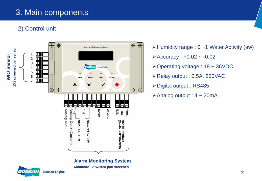
3. Main components
2) Control unit
1
2
3
4
5
6
7
WIO
Se
ns
or
1X
1 s
cre
en
ed
per
sen
so
r
Alarm Monitoring System
Multicore 12 twisted pair screened
TR
X+
TR
X-
S.G
.
24V
DC
0V
DC
NO
1. H
HA
LA
RM
RS
48
5 In
terfa
ce
(Mo
db
us R
TU
/AS
CII)
NO
2. H
AL
AR
M
RE
AD
Y
TR
X+
TR
X-
S.G
.
24V
DC
0V
DC
NO
1. H
HA
LA
RM
RS
48
5 In
terfa
ce
(Mo
db
us R
TU
/AS
CII)
NO
2. H
AL
AR
M
RE
AD
Y
TR
X+
TR
X-
S.G
.
24V
DC
0V
DC
NO
1. H
HA
LA
RM
RS
48
5 In
terfa
ce
(Mo
db
us R
TU
/AS
CII)
NO
2. H
AL
AR
M
RE
AD
Y
TR
X+
TR
X-
S.G
.
24V
DC
0V
DC
NO
1. H
HA
LA
RM
RS
48
5 In
terfa
ce
(Mo
db
us
RT
U/A
SC
II)
NO
2. H
AL
AR
M
RE
AD
YA
nalo
g O
ut +
(Cu
rren
t)
An
alo
g O
ut -
Humidity range : 0 ~1 Water Activity (aw)
Accuracy : +0.02 ~ -0.02
Operating voltage : 18 ~ 36VDC
Relay output : 0.5A, 250VAC
Digital output : RS485
Analog output : 4 ~ 20mA

51
3. Main components
3) DMU (Data Monitoring Unit)
4) Software program
Mounted in ECR console
Real time oil condition monitoring
Display oil condition trend
Touch screen PC with UPS
Data Monitoring Unit is an option item !
Software program for Personal Computer
DMU can be substituted by this software program.
52
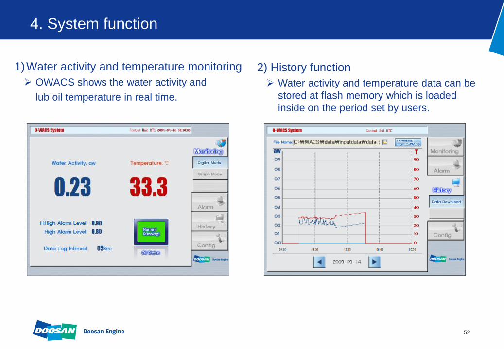
4. System function
1)Water activity and temperature monitoring
OWACS shows the water activity and
lub oil temperature in real time.
2) History function
Water activity and temperature data can be
stored at flash memory which is loaded
inside on the period set by users.

53
5. Specification
1.Water activity
- Measuring range : 0 ~ 1 aw
- Accuracy : ±0.02 aw, ±3.0 aw (≥0.90 aw)
- Response time with stainless steel filter at 20 ˚C : ≥ 10min in still oil
2.Temperature
- Working range : -50 ~ 200 ˚C
- Temperature sensor element : PT100 ohm (Tolerance class A)
- Accuracy : ±0.2 ˚C
3.Transmission Outputs
- Analogue outputs
Y2 : T(-50 ~ 250), 4 ~ 20mA, Load resistance ≤ 500 ohm
Y3 : aw(0.00 ~ 1.00), 4 ~ 20mA, Load resistance ≤ 500 ohm
4.Relay Outputs
- Three freely selectable relay outputs : three a contact
(normal state : ≤0.7aw, alarm state : ≥0.8aw, fault state : ≥ 1.0aw)
5.General
- Supply voltage : 15 ~ 32V DC
- Current consumption : 12 ~ 24 V DC
- Pressure range for tight probe : 0.01 ~ 20bar
- Cable grand : M24 (Aluminum)

54
6. How to retrofit?
1) Installation of Control unit
When installing diesel engine for a ship, install it by using L-bracket and vibration proof pad.
L-Bracket
Vibration proof pad
55
6. How to retrofit?
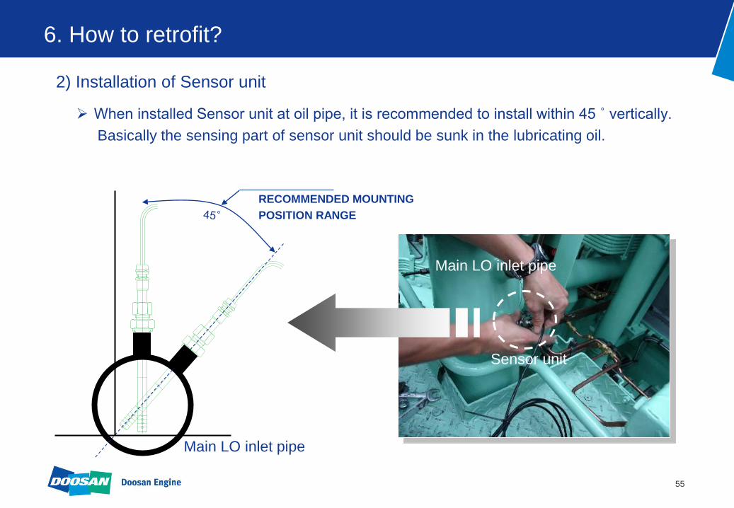
2) Installation of Sensor unit
When installed Sensor unit at oil pipe, it is recommended to install within 45 ˚ vertically.
Basically the sensing part of sensor unit should be sunk in the lubricating oil.
RECOMMENDED MOUNTING
POSITION RANGE
Sensor unit
Main LO inlet pipe
Main LO inlet pipe

56
MODIFICATION TIME CHART
1 2 3 4
Controller
Sensing Module
Supervision Commisioning of System
REMARK 2 WORKING PEOPLE
Retrofit Schedule for WIO System
Electric Cabling
Installation of
WIO
Component
PROCEDUREWORKING DAY
6. How to retrofit?

57
7. Scope of supply
1) Package 1 (Full package)
Doosan delivers material, installation work and commissioning.
AMS interface is optional.
DMU is an option item.
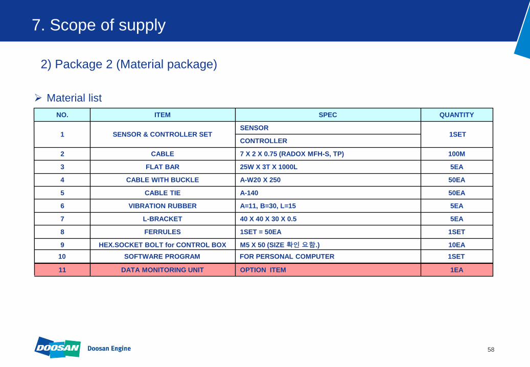
2) Package 2 (Material package)
Doosan delivers below items.
A. Material
B. Quick installation guide
C. Software for personal computer
DMU is an option item.
58
1SET FOR PERSONAL COMPUTER SOFTWARE PROGRAM 10
7. Scope of supply
1EA OPTION ITEM DATA MONITORING UNIT 11
10EA M5 X 50 (SIZE 확인 요함.) HEX.SOCKET BOLT for CONTROL BOX 9
1SET 1SET = 50EA FERRULES 8
5EA 40 X 40 X 30 X 0.5 L-BRACKET 7
5EA A=11, B=30, L=15 VIBRATION RUBBER 6
50EA A-140 CABLE TIE 5
50EA A-W20 X 250 CABLE WITH BUCKLE 4
5EA 25W X 3T X 1000L FLAT BAR 3
100M 7 X 2 X 0.75 (RADOX MFH-S, TP) CABLE 2
CONTROLLER 1SET
SENSOR SENSOR & CONTROLLER SET 1
QUANTITY SPEC ITEM NO.
2) Package 2 (Material package)
Material list

59
The Best Solution for Temperature Monitoring
TEMPERATURE MONITORING SYSTEM
60
Contents
1.Why Bearing Temperature Monitoring?
2.What is DOOSAN Bearing Temperature Monitoring?
3.Why Liner wall Temp Monitoring?
5.Our Temperature Monitoring Solution
4.What is DOOSAN Liner wall Temp Monitoring?

61
1. Why Bearing Temperature Monitoring?
1) In 2-stroke engine, approx. 10% of all damages reported to classification
societies related to bearings.
It may result in repair periods counted in weeks or even months!
With crankshaft related failures, which can result in notations in the class book,
influence the market value of the vessel negatively!
62
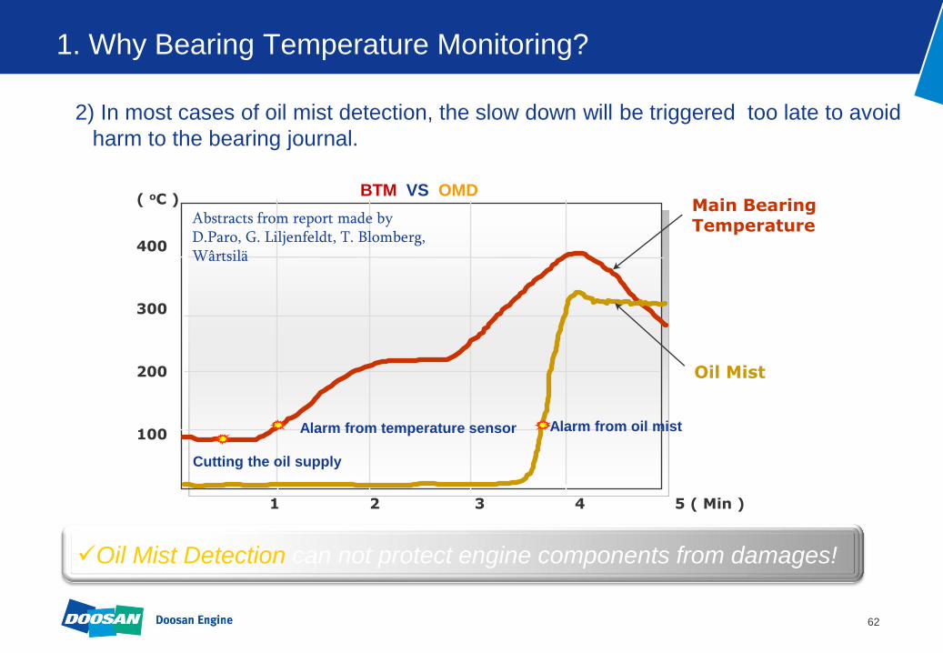
1. Why Bearing Temperature Monitoring?
1 2 3 4 5 ( Min )
( oC ) 400 300 200 100
Main Bearing Temperature
Oil Mist
Cutting the oil supply
Alarm from oil mist Alarm from temperature sensor
Abstracts from report made by D.Paro, G. Liljenfeldt, T. Blomberg, Wârtsilä
BTM VS OMD
2) In most cases of oil mist detection, the slow down will be triggered too late to avoid
harm to the bearing journal.
Oil Mist Detection can not protect engine components from damages!

63
1. Why Bearing Temperature Monitoring?
3) Why DOOSAN temperature monitoring?
Offers real time temperature monitoring.
Can be integrated into any existing alarm and monitoring system.
Fast & reliable response from high quality sensors gives a higher level or safety.
64
2. What is DOOSAN Bearing Temperature Monitoring?
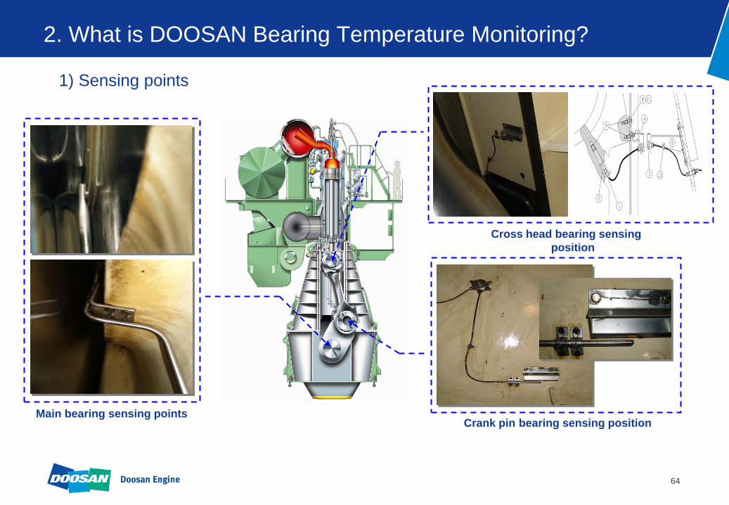
1) Sensing points
Main bearing sensing points
Cross head bearing sensing
position
Crank pin bearing sensing position

65
2. What is DOOSAN Bearing Temperature Monitoring?
Oil supply is the transmitter of bearing temperature to a temp sensor.
Sensor type : Main bearing ( Pt 100Ω )
Crank pin bearing ( Pt 100Ω )
Cross head bearing ( Base – Pt 100Ω , Optional – wireless sensor )
Alarm Monitoring System
Intermediate
Box
Cross head
Crank pin
Main BRG
2) What is DOOSAN bearing temperature monitoring ?

66
2. What is DOOSAN Bearing Temperature Monitoring?
3) Main bearing temperature monitoring
67
2. What is DOOSAN Bearing Temperature Monitoring?
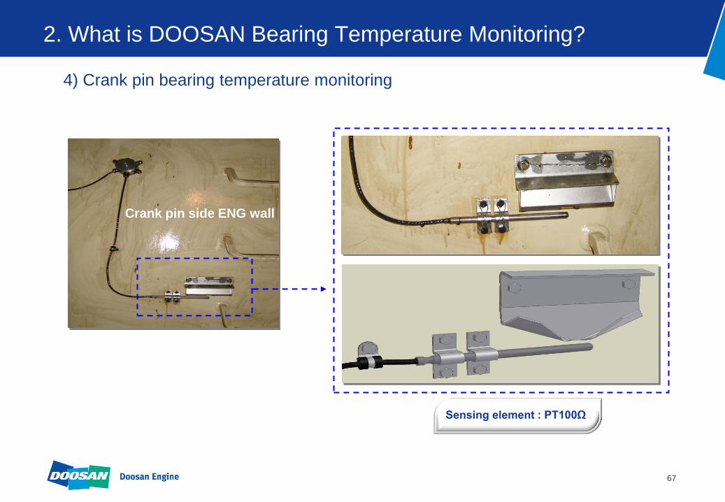
4) Crank pin bearing temperature monitoring
Crank pin side ENG wall
Sensing element : PT100Ω

68
2. What is DOOSAN Bearing Temperature Monitoring?
5) Cross head bearing temperature monitoring
We can install two kinds of sensor at cross head bearing position.
Sensor Type : PT100Ω Sensor Type : Wireless
69
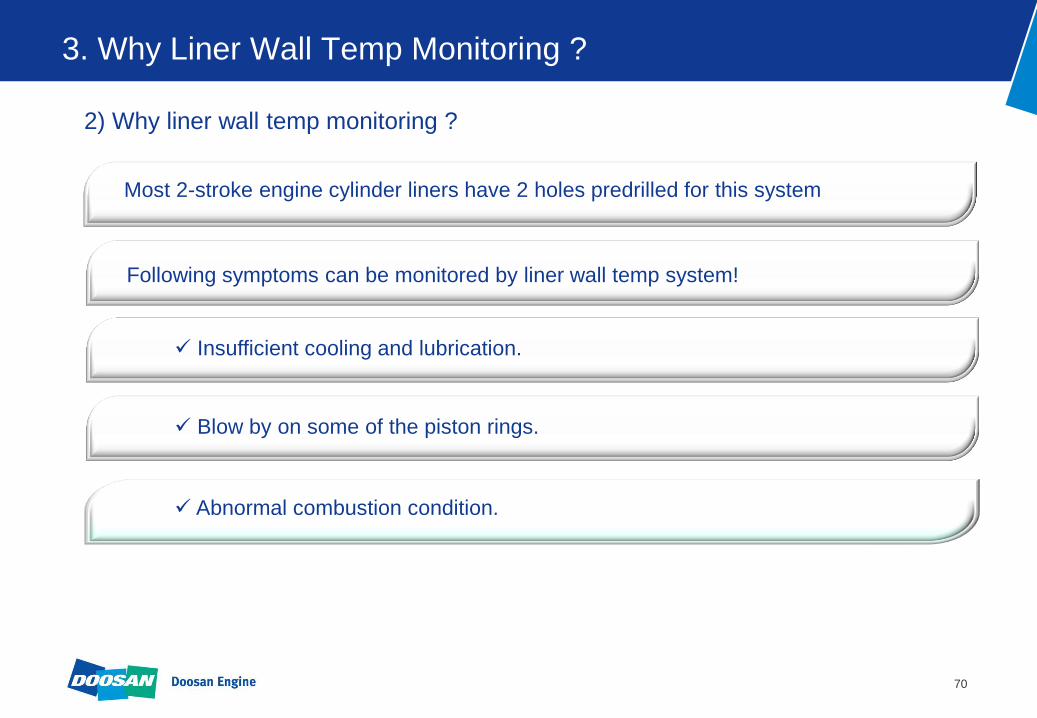
3. Why Liner Wall Temp Monitoring ?
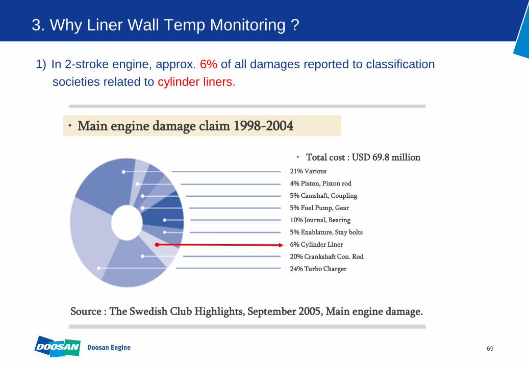
1) In 2-stroke engine, approx. 6% of all damages reported to classification
societies related to cylinder liners.
• Main engine damage claim 1998-2004
• Total cost : USD 69.8 million
21% Various
4% Piston, Piston rod
5% Camshaft, Coupling
5% Fuel Pump, Gear
10% Journal, Bearing
5% Enablature, Stay bolts
6% Cylinder Liner
20% Crankshaft Con. Rod
24% Turbo Charger
Source : The Swedish Club Highlights, September 2005, Main engine damage.
70
3. Why Liner Wall Temp Monitoring ?
2) Why liner wall temp monitoring ?
Following symptoms can be monitored by liner wall temp system!
Insufficient cooling and lubrication.
Blow by on some of the piston rings.
Abnormal combustion condition.
Most 2-stroke engine cylinder liners have 2 holes predrilled for this system

71
4. What is DOOSAN liner wall temp monitoring ?
1) What is DOOSAN liner wall temp monitoring ?
Measuring the temperature in the upper part of the cylinder 5~6mm from the
inner surface.
Alarm, Slow down can be set on the AMS system.
Sensor spec.
• Type : Thermocouple
• Ambient temp : 0 ~ 70°c
• Circuit current : 4 ~ 20 mA
• Accuracy : ± 0.75 %
• Measuring range : 0 ~ 600 °c
• Power source : DC 24V
Components
Temperature sensor
Converter

72
4. What is DOOSAN liner wall temp monitoring ?
2) Install position
Alarm Monitoring System
sensor
Inside
Converter box

73
5. Our temperature monitoring system solution !
Liner wall
X-head bearing
Crank pin bearing
Main bearing
Alarm monitoring system
Converter box
Intermediate box
SYSTEM LAY OUT

74
Reducing Fuel oil consumption & Exhaust emissions
TURBOCHARGER CUT OUT SYSTEM

75
Contents
1. Why Turbocharger cut out ?
2. Benefits
3. Concept of Turbocharger cut out
4. How to retrofit ?
5. Approval of document after Turbocharger cut out
6. Service Experience

76
1. Why Turbocharger cut out ?
1)Purpose of T/C Cut out system
Reduce fuel oil consumption
Reduce exhaust emission
Optimize cargo capacity in fleet
Due to the current economical crisis, it is noticed that some ship-owners, have large
container vessels, are considering operating their vessels with slow speed in order to
reduce main-engine fuel consumption.
To meet this growing demand, turbocharger cut out system has been introduced to
Improve engine performance during low-load operation.
77
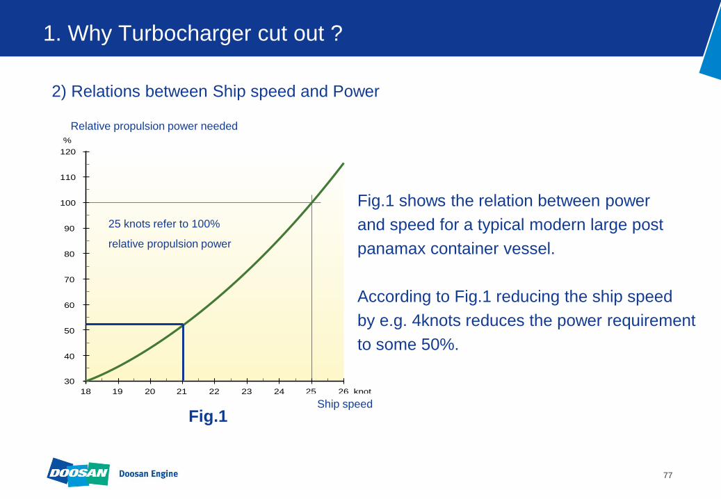
1. Why Turbocharger cut out ?
Fig.1 shows the relation between power
and speed for a typical modern large post
panamax container vessel.
According to Fig.1 reducing the ship speed
by e.g. 4knots reduces the power requirement
to some 50%.
26
Ship speed
knot25242322212019
Relative propulsion power needed
120
%
110
100
90
80
70
60
50
40
18
30
Relative propulsion power needed
25 knots refer to 100%
relative propulsion power
Fig.1 Ship speed
2) Relations between Ship speed and Power

78
1. Why Turbocharger cut out ?
3) Technical considerations of ship power reduction !
Operating at low speed in the 30-50% load area can create problems.
Depositing of soot particles in exhaust gas boiler
Build up of soot in turbocharger
Frequently cut in/out of auxiliary blowers
Increased heat load on components
79
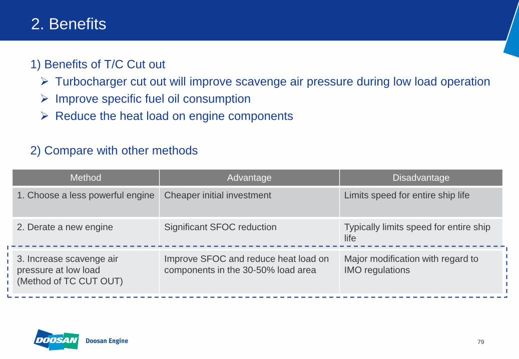
2. Benefits
1) Benefits of T/C Cut out
Turbocharger cut out will improve scavenge air pressure during low load operation
Improve specific fuel oil consumption
Reduce the heat load on engine components
2) Compare with other methods
Method Advantage Disadvantage
1. Choose a less powerful engine Cheaper initial investment Limits speed for entire ship life
2. Derate a new engine Significant SFOC reduction Typically limits speed for entire ship
life
3. Increase scavenge air
pressure at low load
(Method of TC CUT OUT)
Improve SFOC and reduce heat load on
components in the 30-50% load area
Major modification with regard to
IMO regulations
80
2. Benefits
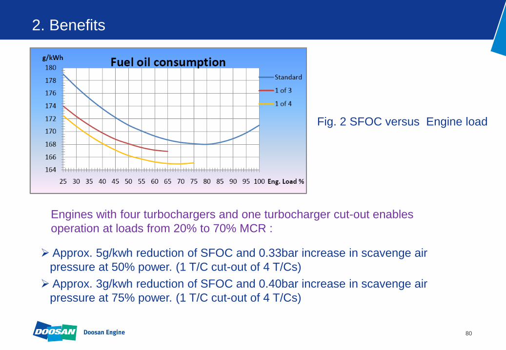
Fig. 2 SFOC versus Engine load
Approx. 5g/kwh reduction of SFOC and 0.33bar increase in scavenge air
pressure at 50% power. (1 T/C cut-out of 4 T/Cs)
Approx. 3g/kwh reduction of SFOC and 0.40bar increase in scavenge air
pressure at 75% power. (1 T/C cut-out of 4 T/Cs)
Engines with four turbochargers and one turbocharger cut-out enables
operation at loads from 20% to 70% MCR :

81
2. Benefits
Fig. 2 SFOC versus Engine load
An SFOC reduction of 1 to 3g/kwh in the power range of 25 to 35% can be
expected.
Engines with four turbochargers and one turbocharger cut-out enables
operation at loads from 10% to 35% MCR :
82
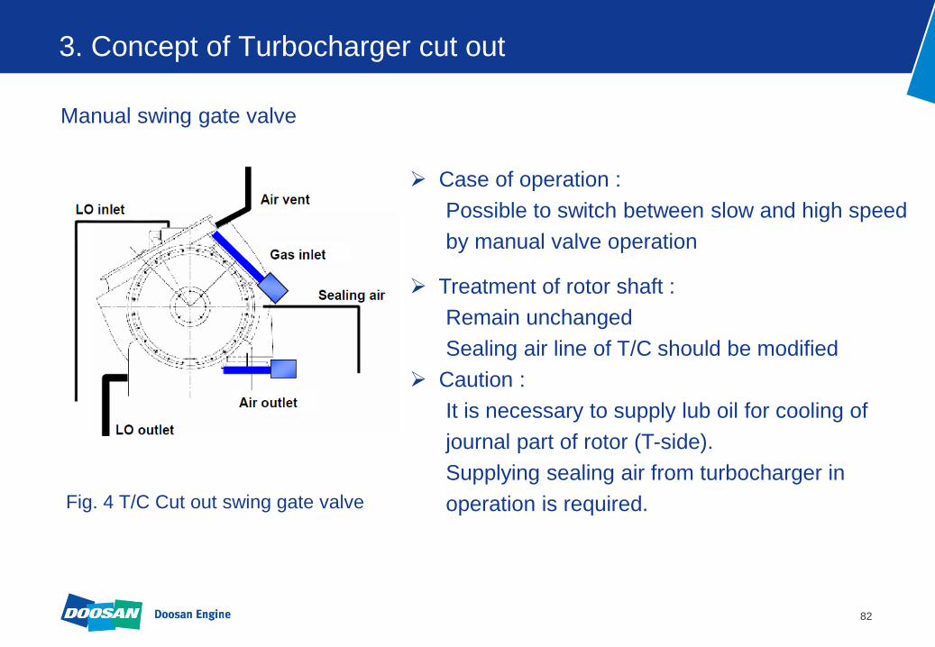
3. Concept of Turbocharger cut out
Manual swing gate valve
Case of operation :
Possible to switch between slow and high speed
by manual valve operation
Treatment of rotor shaft :
Remain unchanged
Sealing air line of T/C should be modified
Caution :
It is necessary to supply lub oil for cooling of
journal part of rotor (T-side).
Supplying sealing air from turbocharger in
operation is required. Fig. 4 T/C Cut out swing gate valve
83
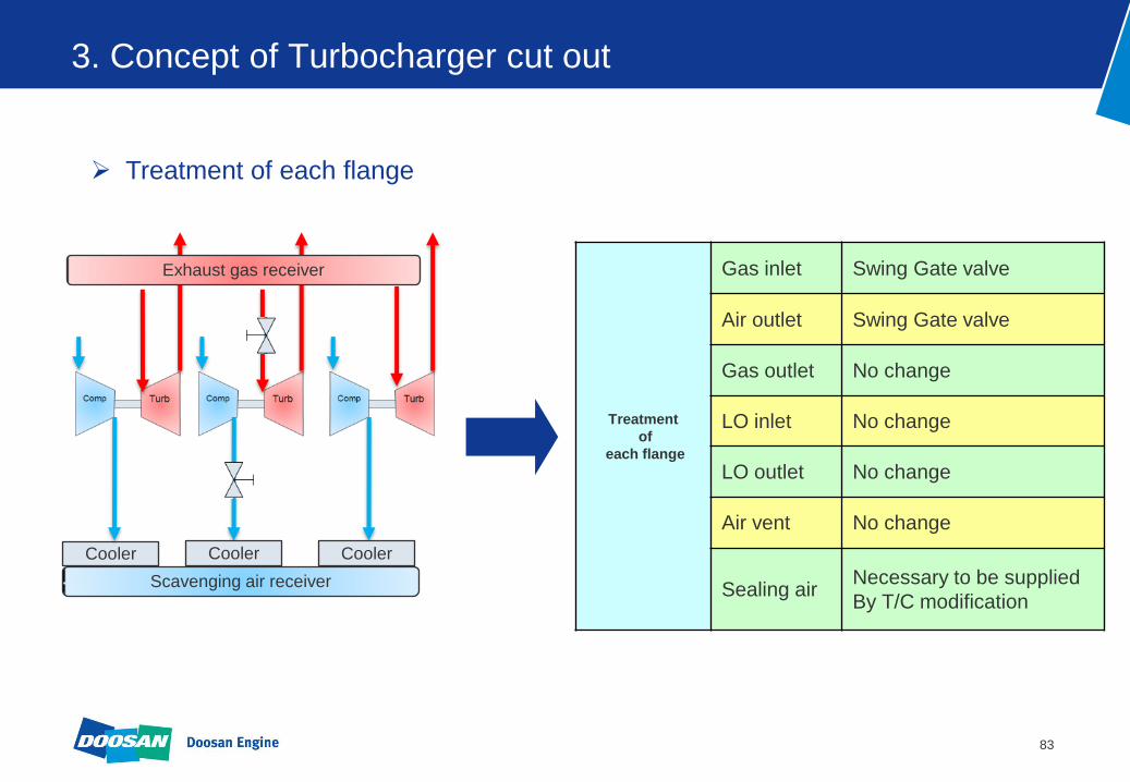
3. Concept of Turbocharger cut out
Treatment
of
each flange
Gas inlet Swing Gate valve
Air outlet Swing Gate valve
Gas outlet No change
LO inlet No change
LO outlet No change
Air vent No change
Sealing air Necessary to be supplied
By T/C modification
Treatment of each flange
Scavenging air receiver
Cooler
Exhaust gas receiver
Cooler Cooler

84
4. How to retrofit ? (Swing gate Valves)
1) Install swing gate valve at turbine side.

85
4. How to retrofit ? (Swing gate Valves)
2) Install swing gate valve at compressor side.

86
4. How to retrofit ? (Swing gate Valves)
3) Install control panel and modify main air valve

87
4. How to retrofit ? (Swing gate Valves)
4) Install and modify T/C sealing air line
Fig. 5 Modify oil labyrinth
Fig. 6 Modify supporter
In case of MHI turbocharger

88
4. How to retrofit ? (Swing gate Valves)
5) Install indicator panel

89
5. Approval of document before T/C Cut out
1) In case of turbocharger cut off, it is considered as a major conversion in
accordance with Reg.13(2)(a) of MARPOL Annex Ⅵ.
2) Therefore the engine shall be carried out NOx emission test to ensure that
it still complies with the NOx emission limits contained in Reg.13 of MARPOL
Annex Ⅵ.
3) But if your engines are meet the following conditions, NOx emission test can
be omitted by common documentation.
Engine type is K98ME/ME-C, K98MC/MC-C
Three or four T/C
Only one T/C is cut out
Exhaust valve timing & Fuel injection timing is unchanged

90
6. Service Experience
Installed swing gate valve - Engine : Doosan MAN-B&W 12K98MC-C (T/C type : MET83MA x 4 sets)
- Test date : 2010.12.20 ( Sea trial )
15.86g/kwh reduction of SFOC at 50% load
* Need to go further for long term measurements
[Normal mode] [T/C Cut Out Mode]
* Yearly operating hours: 7,000 hrs
Reduction 4,085 ton/year
91
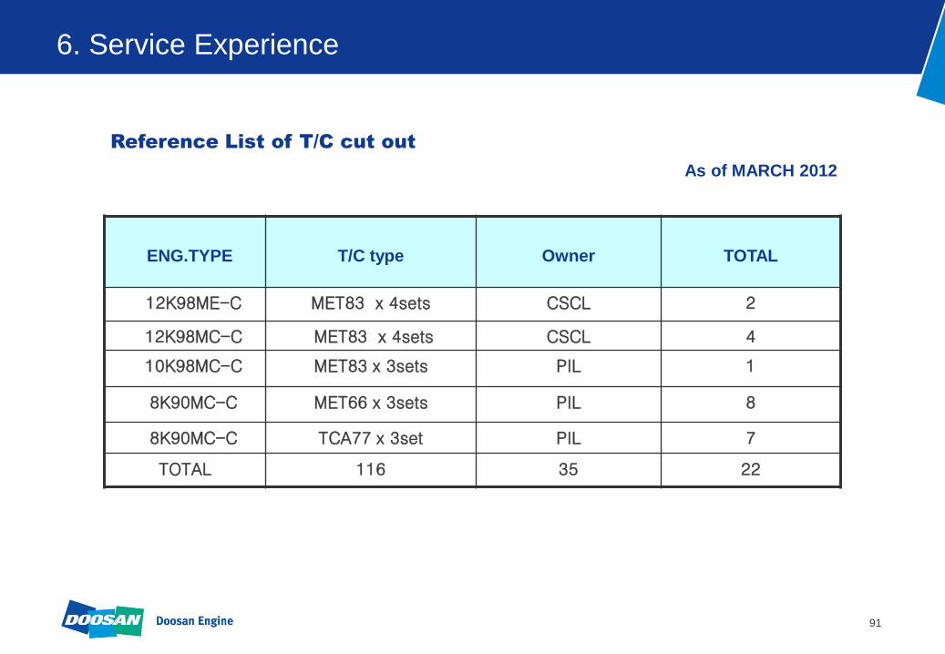
6. Service Experience
As of MARCH 2012
ENG.TYPE
T/C type
Owner
TOTAL
12K98ME-C MET83 x 4sets CSCL 2
12K98MC-C MET83 x 4sets CSCL 4
10K98MC-C MET83 x 3sets PIL 1
8K90MC-C MET66 x 3sets PIL 8
8K90MC-C TCA77 x 3set PIL 7
TOTAL 116 35 22
Reference List of T/C cut out

92
Approved Method File for Pre-2000 engines
The Best Solution for the Pre-2000 engines

93
Contents
1. Approved Method Files for MAN Engines
2. NOx Technical Code 2008
3. Benefits
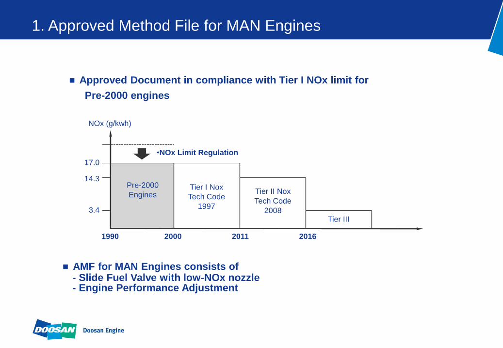
AMF for MAN Engines consists of - Slide Fuel Valve with low-NOx nozzle - Engine Performance Adjustment
•AMF
Pre-2000
Engines
1990 2000 2011 2016
NOx (g/kwh)
17.0
14.3
3.4
Tier I Nox
Tech Code
1997
Tier II Nox
Tech Code
2008 Tier III
•NOx Limit Regulation
Approved Document in compliance with Tier I NOx limit for
Pre-2000 engines
1. Approved Method File for MAN Engines

The revised MARPOL Annex VI and NOx Technical Code 2008
Enter force on 1 July 2010.
The Engines should comply with IMO Tier I NOx limit.
Application (for example : 7S70MC)
Date of approval
- Marine Diesel Engines - Installed on a Ship Constructed, 1 JAN 1990 ~ 1 JAN 2000 - Power output of more than 5,000 kW - Cylinder displacement at or above 90 liters
1st Vessel
5 years
Last Vessel
1 years
Lead time Depending on certificate renewal date
(renewal survey)
5th. Oct. 2010 6th. Oct. 2011 6th. Oct. 2016
•AMF
2. Nox Technical Code 2008
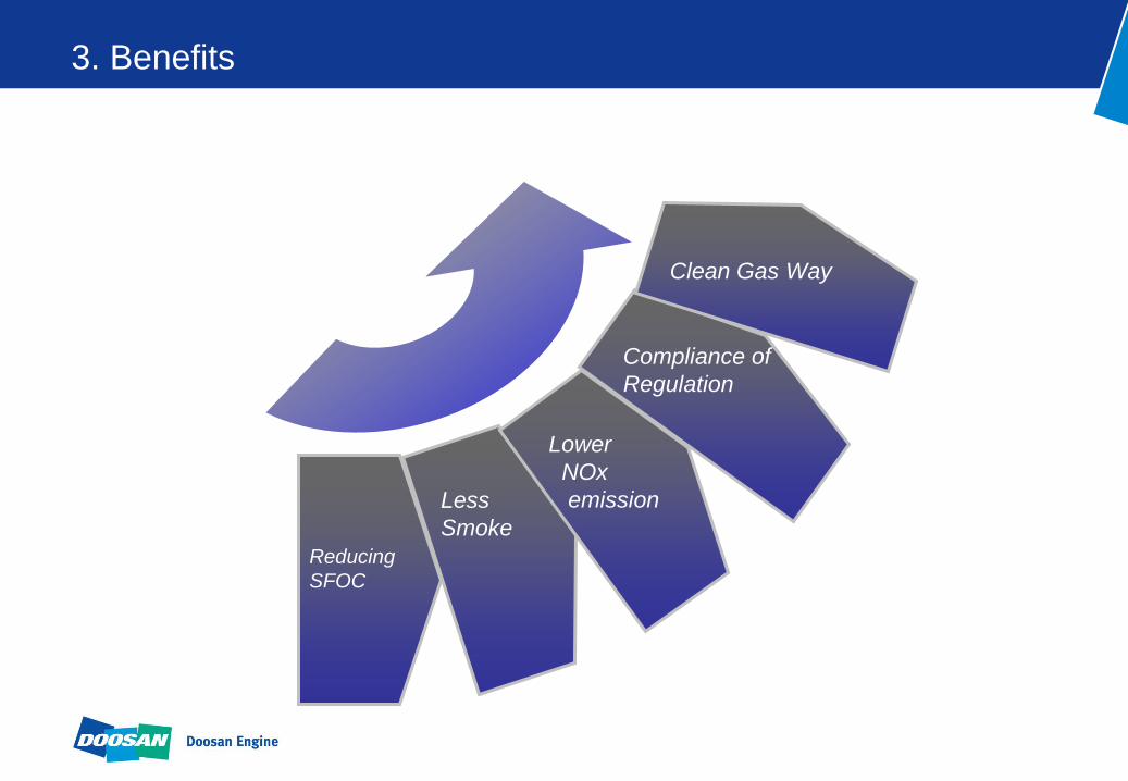
Reducing
SFOC
Less
Smoke
Lower
NOx
emission
Compliance of
Regulation
Clean Gas Way
•AMF
3. Benefits

97
Contact Point
Kim, yunki
General manager
Tel: 82-55-260-6530
E-mail: [email protected]
Park, dong gyu
Tel : 82-55-260-6137
E-mail : [email protected]
Cho, doo hyeong
Tel : 82-55-260-6138
E-mail : [email protected]
Part Sales & Technical Service Team
www.doosanengine.com

98
Your Choice! Your Success!
Your success partner
Doosan Engine
- Thank you -