dong feng df-4bs 6v - edison opto opto datasheet... · dong feng df-4bs 6v features ... dong...
TRANSCRIPT

01
2016. 06. 20
Datasheet HeadLamp Series Version 0.3
HeadLampDong Feng DF-4BS 6V
Features
• Excellent Brightness: 1550lm@ 2A
• Low thermal resistance
• Color: According to ECE/SAE
Applications
• Exterior Automotive Lighting
• Daytime Running Light
• High Beam/ Low Beam for headlight
Dong Feng Headlamp series delivers unique brilliant light with outstanding efficiency and elegant design. It's able to meet requirements of output and stability due to it's developed and tested to withstand extreme environment conditions and wide range of temperature change. It also provides distinct optical performance and uniform light pattern. With Dong Feng's HeadLamp series, you will start to experience and enjoy the excellent adventure during driving time.

02
2016. 06. 20
Version 0.3 HeadLamp Series
Ordering Information
Type
Luminous Intensity
IF = 2000mA
IV [lm]
Ordering Code
Dong Feng-4BS 6V 1550 2DF415CW06DB4003
2 D F 4 1 5 C W x x D B 4 x x xX1 X2 X3-X4 X5-X6 X7-X8 X9-X10 X11-X13 X14-X16
X1Type
X2Emitter Series
X3-X4Emitter Series
X5-X6Emitter Power
X7-X8Emitting Color
Code Type Code Type Code Type Code Type Code Type
2 Emitter D Dong Feng F4 4Chip 15 15W CW Cool White
X9-X10Internal Code
X11-X13PCB Board
X14-X16Series No.
Code Type Code Type Code Type
- - DB4 19x75 xxx -

03
2016. 06. 20
Version 0.3 HeadLamp Series
Maximum Ratings
Parameter Symbol Values Unit
DC Forward Current (TS = 25°C) IF - mA
Peak Pulsed Current; (tp≤400ms, Duty cycle=10%) Ipulse 4000 mA
Thermal Resistance - - K/W
Reverse Voltage[1] VR Note1 V
LED Junction temperature Tj 150 °C
Operating temperature Topr -40~+105 °C
Storage temperature Tstg -40~+125 °C
LEDs are not designed to drive in reverse bias.NOTE

04
2016. 06. 20
Version 0.3 HeadLamp Series
Characteristics (TS = 25 °C; IF = 2000 mA)
Parameter Symbol Values Unit
Luminous Flux (typ.) - 1550 lm
Viewing angle (typ.) 2ϕ 120 °
Forward voltage (typ.) VF 6.3 V
2ϕ is the off-axis angle where the luminous intensity is half of the axial luminous intensity.NOTE

05
2016. 06. 20
Version 0.3 HeadLamp Series
Brightness Groups
Group(min.) Luminous Intensity
Iv [lm]
(max.) Luminous Intensity
Iv [lm]
N0 1000 1120
O0 1120 1250
P0 1250 1400
Q0 1400 1600
R0 1600 1800
Forward Voltage Groups
Group(min.) VF
[V]
(max.) VF
[V]
V61 5.45 5.95
V62 5.95 6.45
V63 6.45 6.95
V64 6.95 7.45

06
2016. 06. 20
Version 0.3 HeadLamp Series
Chromaticity Coordinate Groups
Color Chromaticity Groups
Group Cx Cy
01H
0.3241 0.3534
0.3248 0.3370
0.3350 0.3460
0.3355 0.3633
02H
0.3190 0.3430
0.3203 0.3274
0.3298 0.3526
0.3299 0.3361
Group Cx Cy
03H
0.3145 0.3330
0.3163 0.3181
0.3246 0.3424
0.3253 0.3266
04H
0.3104 0.3234
0.3127 0.3093
0.3199 0.3325
0.3212 0.3175
01H
02H
03H
04H

07
2016. 06. 20
Version 0.3 HeadLamp Series
Relative Spectral Emission - V(λ) = Standard eye response curve
Irel = f (λ); TS = 25°C; IF = 2000mA
Radiation Characteristics
Irel = f (λ); TS = 25°C
120
100
80
60
40
20
0 400 450 500 550 600 650 700 750 800
Nor
mal
ized
lum
inou
s In
tens
ity(%
)
Wavelength(nm)
Arb
itrar
y U
nit (
A.U
)
Radiation Angle

08
2016. 06. 20
Version 0.3 HeadLamp Series
Forward Current
IF = f (VF); TBoard = 25°C
Chromaticity Coordinate Shift
ΔCx, ΔCy = f(IF); TBoard = 25 °C
lF [mA]
VF [V]
Relative Luminous Intensity
IV/IV (2000mA) = f(IF) ; TBoard = 25°C
lF [mA] 0 1000 2000 3000 4000
lF [mA]
CxCy
Cx Cy
0.390
0.380
0.370
0.360
0.350
0.340
0.330
0.320 0 1000 2000 3000 4000
Relative Luminous Intensity
IV/IV(25°C) = f(Tj); IF = 2000mA
Temperature
1.00
0.98
0.96
0.94
0.92
0.90
0.88
0.86
0.84 25 40 55 70 85 100
lmlm(25°C)
5 5.5 6 6.5 7 7.5 8
1.6
1.4
1.2
1.0
0.8
0.6
0.4
0.2
0
4000
3500
3000
2500
2000
1500
1000
500
0
lmlm(2000mA)

09
2016. 06. 20
Version 0.3 HeadLamp Series
Relative Forward Voltage
ΔVF = VF-VF(25°C) = f(Tj); IF = 2000mA
Chromaticity Coordinate Shift
Cx, Cy = f(IF); IF = 2000mA
Temperature Temperature
CxCy Cx
Cy
25 40 55 70 85 100 25 40 55 70 85 100
ΔVF(V) 0.00
-0.05
-0.10
-0.15
-0.20
-0.25
-0.30
0.365
0.360
0.355
0.350
0.345
0.340
0.335
0.330
0.325
10
2016. 06. 20
Version 0.3 HeadLamp Series
6.474
1.52
4
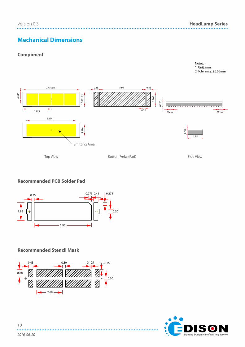
Mechanical Dimensions
Recommended PCB Solder Pad
Recommended Stencil Mask
+ -
Component
Top View Bottom Veiw (Pad) Side View
Notes: 1. Unit: mm.2. Tolerance: ±0.05mm
Emitting Area
0.275
5.95
1.85 0.50
0.25 0.450.275
0.125
2.68
0.80
0.30
0.45 0.30 0.125
+ -
1.85
0.72
0
0.4500.250
0.72
0
3.725
7.450±0.1
1.90
0±0.
1
0.95
0
1.90
0
+
0.45 5.95 0.45
0.30

11
2016. 06. 20
Version 0.3 HeadLamp Series
Reflow Profile
Parameter SymbolPb-Free (SnAgCu) Assembly
UnitMinimum Recommendation Maximum
Preheat and Soak temperature(Tsmin to Tsmax)
Ts 150 150~200 200 °C /s
Time ts(Tsmin to Tsmax)
ts 60 - 120 s
Ramp-up rate to peak(Tsmax to Tp)
- - - 3 °C /s
Liquidus temperature TL 217 °C
Time above liquidus temperature tL 60 - 150 s
Peak temperature Tp 255 - 260 °C
Time** within 5°C of the specified classification temperature
tp - 30 - s
Average ramp-down rate(Tp to Tsmax)
- - - 6 °C /s
Time 25°C to peak temperature - - - 8 min
Notes:
1. * Tolerance for peak profile temperature (Tp) is defined as a supplier minimum and a user maximum.
2. ** Tolerance for time at peak profile temperature (tp) is defined as a supplier minimum and a user maximum.

12
2016. 06. 20
Version 0.3 HeadLamp Series
Pick and Place
• Dong feng series is compatible for all kind of SMT instrument.
• Using the recommended nozzle design can be more accurate during the SMT process.
Parameter CN140
Outside Diameter(x) 02.2
Inside Diameter(y) 01.4
Material Ceramic
• Recommended Nozzle Specification

13
2016. 06. 20
Version 0.3 HeadLamp Series
Unit: mm16 mm tape with 3000 PCS on Φ178 mm reel
W E1 F P0 P1 P2 D0 A0 B0 K0
16 ± 0.3 1.75 ± 0.1 7.5 ± 0.1 4.0 ± 0.1 4.0 ± 0.1 2.0 ± 0.1 1.5 +0.1/-0 2.2 ± 0.1 7.75 ±0.1 1.15 ± 0.1
A N W1 W2 W3 D B C
178 ± 1.0 60 ± 0.5 17 +0.5/-0 20 ± 0.5 >16 21.3 ± 0.2 2.3 ± 0.2 13.5 ± 0.2
Tape Dimensions
Reel Dimensions
Product Packaging information
14
2016. 06. 20
Version 0.3 HeadLamp Series
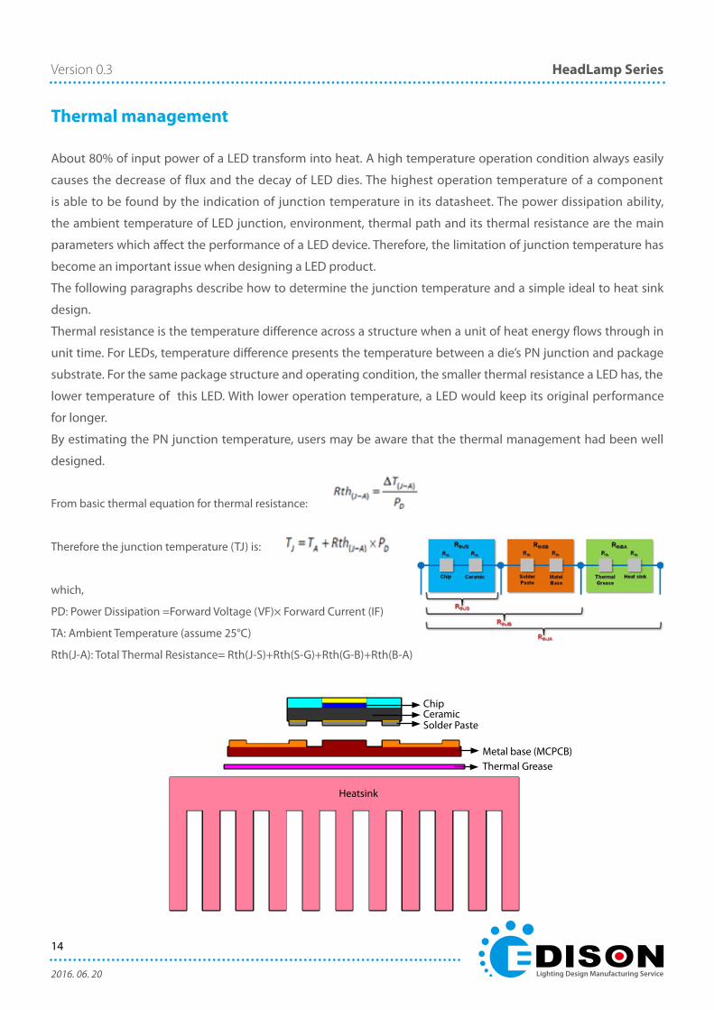
Thermal management
About 80% of input power of a LED transform into heat. A high temperature operation condition always easily
causes the decrease of flux and the decay of LED dies. The highest operation temperature of a component
is able to be found by the indication of junction temperature in its datasheet. The power dissipation ability,
the ambient temperature of LED junction, environment, thermal path and its thermal resistance are the main
parameters which affect the performance of a LED device. Therefore, the limitation of junction temperature has
become an important issue when designing a LED product.
The following paragraphs describe how to determine the junction temperature and a simple ideal to heat sink
design.
Thermal resistance is the temperature difference across a structure when a unit of heat energy flows through in
unit time. For LEDs, temperature difference presents the temperature between a die’s PN junction and package
substrate. For the same package structure and operating condition, the smaller thermal resistance a LED has, the
lower temperature of this LED. With lower operation temperature, a LED would keep its original performance
for longer.
By estimating the PN junction temperature, users may be aware that the thermal management had been well
designed.
From basic thermal equation for thermal resistance:
Therefore the junction temperature (TJ) is:
which,
PD: Power Dissipation =Forward Voltage (VF)× Forward Current (IF)
TA: Ambient Temperature (assume 25°C)
Rth(J-A): Total Thermal Resistance= Rth(J-S)+Rth(S-G)+Rth(G-B)+Rth(B-A)
Heatsink
Thermal GreaseMetal base (MCPCB)
Solder PasteCeramicChip
15
2016. 06. 20
Version 0.3 HeadLamp Series
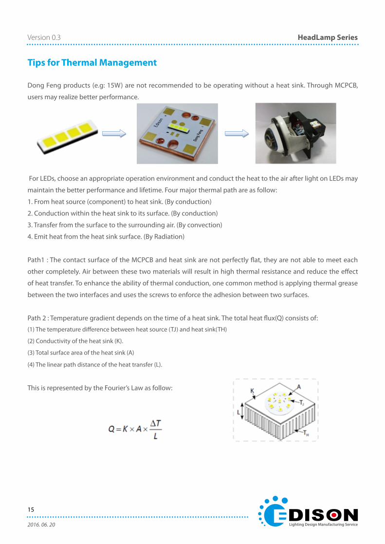
Tips for Thermal Management
Dong Feng products (e.g: 15W) are not recommended to be operating without a heat sink. Through MCPCB,
users may realize better performance.
For LEDs, choose an appropriate operation environment and conduct the heat to the air after light on LEDs may
maintain the better performance and lifetime. Four major thermal path are as follow:
1. From heat source (component) to heat sink. (By conduction)
2. Conduction within the heat sink to its surface. (By conduction)
3. Transfer from the surface to the surrounding air. (By convection)
4. Emit heat from the heat sink surface. (By Radiation)
Path1 : The contact surface of the MCPCB and heat sink are not perfectly flat, they are not able to meet each
other completely. Air between these two materials will result in high thermal resistance and reduce the effect
of heat transfer. To enhance the ability of thermal conduction, one common method is applying thermal grease
between the two interfaces and uses the screws to enforce the adhesion between two surfaces.
Path 2 : Temperature gradient depends on the time of a heat sink. The total heat flux(Q) consists of:
(1) The temperature difference between heat source (TJ) and heat sink(TH)
(2) Conductivity of the heat sink (K).
(3) Total surface area of the heat sink (A)
(4) The linear path distance of the heat transfer (L).
This is represented by the Fourier’s Law as follow:

16
2016. 06. 20
Version 0.3 HeadLamp Series
By choosing a higher thermal conductivity, increasing the surface area of the heat sink (add the number of fins)
or shorten the distance of the linear path of heat dissipation may improve the lose of heat flux per unit time.
Among all materials, metals is the best choice because of its high thermal conductivity.
Path3 : Heat dissipation includes convection and radiation. Those two types of transfer are proportional to the
surface area of the heat sink. Adding the number of fin may increase the total surface area. However, too many
fins may cause inhabitation of convection. There are many other thermal management methods such as install
a fan to reach obliged convection. But this design may cause the issues such as noise or circuit design problem.
Path 4 : Compare with an unfinished heat sink, the one that covered by high emissivity material, such as ceramic
powder or deep color paint, usually has better radiation ability. Both anodizing and etching are also effective to
increase the thermal dissipation.
Key Points for thermal management:
• Thecontactsurface’sflatnessandsmoothnessofthecomponentandheatsink.
• Thetotalsurfaceareaofheatsink.
• Theselectionofheatsinkmaterial.
Optimum number of fins. (Aerodynamic optimization)

17
2016. 06. 20
Version 0.3 HeadLamp Series
Recommended PCB Design
The PCB design can affect the thermal performance of the end product. In order to reduce the thermal
resistance of PCB, heat must transfer through metal without dielectric layer. The figure below shows the cross
-section of PCB.
Handling Manual
• Plastic Tweezers
• Metal Tweezers
V X
XX
Dong Feng Series LED use phosphor film on the emitting surface, sealing by silicon. LED may be deformed or
destructed if excessive force is applied.
When manual handling the LED, please use the plastic tweezers instead of the metal one.
Avoid contacting to the white silicon structure which will cause damage to the package.
18
2016. 06. 20
Version 0.3 HeadLamp Series
HS and China RoHS compliants product
符合歐盟 RoHS 指令的要求;中國的相關法規和標準,不含有毒有害物質或元素。