domestic wastewater facilities manual - center for environmental
TRANSCRIPT
DOMESTIC WASTEWATER FACILITIESMANUAL
A GUIDE FOR THE PREPARATION OFAPPLICATIONS, REPORTS AND PLANS
BUREAU OF WATER QUALITY PROTECTION
http://www.dep.state.pa.us
COMMONWEALTH OF PENNSYLVANIADEPARTMENT OF ENVIRONMENTAL PROTECTION
362-0300-001 10/97
DEPARTMENT OF ENVIRONMENTAL PROTECTIONBUREAU OF WATER QUALITY PROTECTION
Document ID: 362-0300-001
Title: Domestic Wastewater Facilities Manual
Effective Date: October 1, 1997
Authority Act 537 of 1966, the Pennsylvania Sewage Facilities Act (as amended), and theClean Streams Law (35 P.S. §§691.1-691.1001) 25 PA Code Chapter 91.
Policy: To improve and preserve the purity of the waters of the Commonwealth for theprotection of public health, animal and aquatic life and for recreation
Purpose: To amend and clarify the existing 8/91 guidance regarding the design andconstruction of domestic wastewater treatment facilities.
Applicability: This policy amends the 8/91 guidance regarding the design and construction ofdomestic wastewater treatment facilities.
Disclaimer: The policies and procedures outlined in this guidance are intended to supplementexisting requirements. Nothing in the policies or procedures shall affect regulatoryrequirements.
The policies and procedures herein are not an adjudication or a regulation. There isno intent on the part of DEP to give the rules in these policies that weight ordeference. This document establishes the framework within which DEP will exerciseits administrative discretion in the future. DEP reserves the discretion to deviatefrom this policy statement if circumstances warrant.
Page Length: 117 Pages
Location: Vol. 33, Tab 33
Definitions: Sewage Facilities: A system of sewage collection, conveyance, treatment anddisposal which will prevent the discharge if untreated adequately treated sewage orother wastes into waters of the Commonwealth or otherwise provide for the safe andsanitary treatment and disposal of sewage.
DOMESTIC WASTEWATER FACILITIES MANUALDEPARTMENT OF ENVIRONMENTAL PROTECTION
COMMONWEALTH OF PENNSYLVANIA
The attached Domestic Wastewater Facilities Manual has been prepared as a guide for persons
responsible for the design and construction of domestic wastewater facilities. It is being sent to
you because you might be interested or because you have requested a copy. The manual is also
available to download from the DEP web site at: http://www.dep.state.pa.us.
The manual may be revised from time to time as the need arises. If you have suggestions for
improvement to this manual or desire that future revisions be sent to you, please return this letter
to us with the following completed information.
NAME
STREET OR ROUTE
CITY STATE
ZIP CODE
This manual could be improved by
___ Yes, send me future revisions.
Send to: Chief, Permits SectionPennsylvania Department of Environmental ProtectionBureau of Water Quality ProtectionRCSOB 11th FloorP.O. Box 8774Harrisburg, PA 17105-8774
PREFACE
The Commonwealth of Pennsylvania provides for the regulation of wastewater disposal “to preserve andimprove the purity of the waters of the Commonwealth for the protection of public health, animal andaquatic life, and for industrial consumption and recreation”.
The manual has been prepared as a guide to those persons responsible for the discharge of treatedwastewater to waters of the Commonwealth and for the construction of sewers, pump stations andtreatment facilities. Parts I and II briefly set forth information regarding the responsibility and thefunctions of the Department of Environmental Protection (Department) in carrying out the policies andprovisions of the Clean Streams Law and the procedure for obtaining permits for discharge and for theconstruction and operation of treatment facilities.
The Department’s policy for conducting technical reviews and approvals of permit applications containedin DEP document #362-2000-007 is applicable to this manual. The policy states that the Department willconsider the registered professional engineer whose seal is affixed to facility design documents to be fullyresponsible for the adequacy of all aspects of the facility design and compliance with the state standardsand requirements. The Department approval or issuance of permit does not, in any way, relieve the designengineer of this responsibility.
Part III is a detailed technical guide for consultants and sanitary engineers, containing minimumrequirements and limiting factors used by the Bureau of Water Quality Protection in the review ofapplications for treatment facilities permits. It has been based primarily on the “Recommended Ten StatesStandards for Wastewater Facilities” adopted by the Great Lakes and Upper Mississippi River Board ofState Public Health and Environmental Managers.
The design of wastewater facilities should not be limited by minimum requirements, but must meet theneeds of the particular situation. It is not the purpose of this manual to set forth data which can be usedwithout due regard for the requirements of the particular project under design. The judgment of the skilledprofessional engineer is still required to apply these data. The Department will apply more stringent criteriawhen, in its judgment, their use is justified. With the foregoing qualifications definitely understood, theDepartment considers the items set forth in Part III of this manual as generally representative of goodengineering practices.
New processes and variations of processes are proposed from time to time. Lack of description or criteriafor a process does not suggest a process should not be used, but only that consideration by the Departmentwill be on the basis of information submitted with a specific design. The manual explains the requirementsfor experimental processes in Section 9.4, entitled “Applications for New Processes”. Data on newlyproven processes are usually meager, and final standards cannot be adopted immediately or included in arevised manual. Tentative standards for such processes will be available as information is submitted andreviewed. The Department reserves the right to amend this manual if and when necessary to incorporatesuch new processes. Any such amendments will be posted on the DEP site and incorporated into themanual then reprinted at a later date.
362-0300-001 / 10/1/97 / Table of Contents / Page i
TABLE OF CONTENTS
PAGEPART I GENERAL INFORMATION
1. Acts of the General Assembly of Pennsylvania .................................................. 12. The Bureau of Water Quality Protection............................................................ 23. Permits ............................................................................................................. 34. Approval by Other Agencies ............................................................................. 4
PART II. PROCEDURE FOR OBTAINING A PERMIT
7. Summary of Procedures .................................................................................... 58. Preliminary Engineering Conference.................................................................. 59. Applications for Wastewater Facilities Permits.................................................. 6
PART III. STANDARDS FOR DOMESTIC WASTEWATER FACILITIES
10. Engineering....................................................................................................... 1111. Designer’s Report ............................................................................................. 1112. Plans ................................................................................................................ 1113. Specifications ................................................................................................... 1414. Revisions to Approved Plans............................................................................. 1515. Operation During Construction ......................................................................... 1516. Blasting During Construction............................................................................ 15
20. Design of Sanitary Sewer Systems .................................................................... 1521. Type of System................................................................................................. 1522. Design Period ................................................................................................... 1623. Design Factors.................................................................................................. 1624. Design Basis..................................................................................................... 1625. Details of Design and Construction ................................................................... 1726. Manholes.......................................................................................................... 2027. Sewers in Relation to Streams ........................................................................... 2228. Protection of Water Supplies............................................................................. 2329. Alternative Sewer Systems................................................................................ 24
30. Wastewater Pumping Stations........................................................................... 2831. General............................................................................................................. 2832. Wet and Dry Well Pump Stations...................................................................... 2833. Suction Lift Pump Stations ............................................................................... 3134. Submersible Pump Stations............................................................................... 3235. Alarm Systems ................................................................................................. 3336. Emergency Operation........................................................................................ 3337. Instructions and Equipment ............................................................................... 3538. Force Mains ..................................................................................................... 35
362-0300-001 / 10/1/97 / Table of Contents / Page ii
TABLE OF CONTENTS
40. Wastewater Treatment Plants............................................................................ 3741. General............................................................................................................. 3742. Quality of Effluent............................................................................................ 3743. Design .............................................................................................................. 3744. Plant Details ..................................................................................................... 4345. Plant Outfalls ................................................................................................... 4546. Power Facilities ................................................................................................ 4547. Safety............................................................................................................... 4748. Operation ......................................................................................................... 50
50. Pretreatment ..................................................................................................... 5151. Screening Devices............................................................................................. 5152. Comminutors .................................................................................................... 5353. Grit Removal Facilities ..................................................................................... 5454. Pre-aeration and Flocculation............................................................................ 5555. Flow Equalization............................................................................................. 56
60. Settling............................................................................................................. 5861. General............................................................................................................. 5862. Design Considerations....................................................................................... 5863. Weirs................................................................................................................ 6064. Sludge and Scum Removal................................................................................ 6165. Protective and Service Facilities ........................................................................ 63
70. Sludge Processing, Storage and Disposal........................................................... 6471. General............................................................................................................. 6472. Sludge Treatment Processes .............................................................................. 6473. Sludge Thickening ............................................................................................ 6474. Anaerobic Sludge Digestion .............................................................................. 6475. Aerobic Sludge Digestion.................................................................................. 6976. Sludge Pumps and Piping.................................................................................. 7077. Sludge Dewatering............................................................................................ 7178. Sludge Storage and Disposal ............................................................................. 73
80. Biological Treatment......................................................................................... 7481. Trickling Filters ................................................................................................ 7482. Activated Sludge............................................................................................... 7783. Rotating Biological Contactors.......................................................................... 8484. Intermittent Sand Filters.................................................................................... 8785. Wastewater Treatment Ponds............................................................................ 8986. Other Biological Treatment Processes ............................................................... 9887. Land Treatment ................................................................................................ 98
90. Advanced Wastewater Treatment ...................................................................... 9991. High Rate Effluent Filtration............................................................................. 9992. Phosphorus Removal by Chemical Treatment .................................................... 100
362-0300-001 / 10/1/97 / Table of Contents / Page iii
TABLE OF CONTENTS
100. Disinfection ...................................................................................................... 104101. General............................................................................................................. 104102. Forms of Disinfection ....................................................................................... 104103. Chlorine Disinfection ........................................................................................ 104104. Dechlorination .................................................................................................. 108105. Ultraviolet (UV) Radiation Disinfection............................................................. 110106. Other Disinfection Processes ............................................................................. 111
362-0300-001 / 10/1/97 / Page 1
PART I
GENERAL INFORMATION
1. ACTS OF THE GENERAL ASSEMBLY OF PENNSYLVANIA
Section 207 of Act No. 394, approved June 22, 1937, P.L. 1987, amended through May 30, 1989,provides as follows:
"Approval of Plans, Designs and Relevant Data by the Department - (a) All plans, designs andrelevant data for the construction of any new sewer system, or for the extension of any existing sewersystem except as provided in section (b), by a person or municipality, or for the erection, construction,and location of any treatment works or intercepting sewers by a person or municipality, shall besubmitted to the department for its approval before the same are constructed or erected or acquired.Any such construction or erection which has not been approved by the department by written permit,or any treatment works not operated or maintained in accordance with the rules and regulations of thedepartment, is hereby also declared to be a nuisance and abatable as herein provided.
(b)Except as specifically provided by the rules and regulations of the department, plans, designs andrelevant data for the construction of a sewer extension to collect no more than the volume of sewagefrom two hundred fifty single family dwelling units OR THEIR EQUIVALENT by a person ormunicipality shall not require a permit from the department if such sewer extension is located,constructed, connected and maintained in accordance with the rules and regulations of the departmentand is consistent with the approved official plan, required by Section 5 of the Act of January 24, 1966(1965 P.L. 1535, No. 537), known as the “Pennsylvania Sewage Facilities Act,” for the municipalityin which the sewer extension is to be located, constructed, connected or maintained. However, allsuch sewer extensions remain subject to any conditions imposed by the department, the municipality,or any municipal authority whose interest may be affected by the sewer extension. Any such sewerextension which is located, constructed, connected or maintained contrary to the rules and regulationsof the department, contrary to the terms and conditions of a permit, inconsistent with the approvedofficial plan for the municipality or contrary to any conditions imposed by the department,municipality or municipal authority is also hereby declared to be a nuisance and abatable as providedherein.”
As defined in the Act,“sewer extension” shall be construed to include new pipelines or conduits, andall other appurtenant constructions, devices and facilities except pumping stations and force mainsadded to an existing sewer system for the purpose of conveying sewage from individual structures orproperties to the existing system.
Copies of Act No. 394, approved June 22, 1937, P.L. 1987, the Clean Streams Law, as amended,may be obtained upon request to any regional office listed in Section 2.3.
1.1 Object - In reviewing reports and plans of proposed wastewater treatment, the Department hasone dominant interest: the protection of the waters of the Commonwealth against pollution,under the provisions of the law. Engineering reports and plans are, therefore, reviewed from thefunctional point of view to assure the suitability, adequacy, and operating reliability of thecontemplated works to prevent stream pollution.
Matters of structural design, mechanical, electrical and other details are subjects of interest tothe Department only to the extent that such items directly affect the functioning of the facilitiesand are necessary to make the project complete and ready for bidding.
362-0300-001 / 10/1/97 / Page 2
Lack of description or criteria for a specific process does not suggest that it should not be used,but only that consideration by the Department will be on the basis of information submitted withthe design.
1.2 Functions - In the exercise of its duties, the Department issues orders for the preparation ofplans of treatment facilities and orders for the construction of such works. Applications forpermits are considered on the basis of the engineering facts presented and, accordingly, permitsare issued or denied.
The Department determines environmental priorities for the award of grants/loans under thePENNVEST program towards the construction of wastewater treatment facilities.
2. THE BUREAU OF WATER QUALITY PROTECTION
2.1 Functions - The Bureau of Water Quality Protection examines and passes upon the technicalaspects of all applications and plans for wastewater projects prior to issuance of a permit.Consistent with DEP Policy #362-2000-007, the design engineer is responsible for all designcomputations and functioning of the proposed facilities.
2.2 Organization - The Bureau maintains regional offices through which it conducts its field workand application review. Matters pertaining to wastewater project applications and theengineering aspects of such projects should be discussed with, and applications filed in, theappropriate regional office.
2.3 Regional offices
HEADQUARTERS COUNTIES SUPERVISED
Regional Water Quality Manager Bucks, Chester, Delaware,Lee Park, Suite 6010 Montgomery, Philadelphia555 North LaneConshohocken, PA 19428Tel: (215) 832-6130
Regional Water Quality Manager Carbon, Lackawanna, Lehigh,2 Public Square Luzerne, Monroe, Northampton,Wilkes-Barre, PA 18711-0790 Pike, Schuylkill, Susquehanna,Tel: (717) 826-2553 Wayne, Wyoming
Regional Water Quality Manager Adams, Bedford, Berks, BlairOne Ararat Boulevard Cumberland, Dauphin, Franklin,Harrisburg, PA 17110 Fulton, Huntingdon, Juniata,Tel: (717) 657-4590 Lancaster, Lebanon, Mifflin,
Perry, York
Regional Water Quality Manager Bradford, Cameron, Centre,208 W. 3rd Street, Suite 101 Clearfield, Clinton, Columbia,Williamsport, PA 17701 Lycoming, Montour, Northumberland,Tel: (717) 327-3669 Potter, Snyder, Sullivan, Tioga,
Union
Regional Water Quality Manager Allegheny, Armstrong, Beaver,400 Waterfront Drive Cambria, Fayette, Greene,Pittsburgh, PA 15222 Indiana, Somerset, Washington,
362-0300-001 / 10/1/97 / Page 3
Tel: (412) 442-4000 Westmoreland
Regional Water Quality Manager Butler, Clarion, Crawford,230 Chestnut Street Elk, Erie, Forest, Jefferson,Meadville, PA 16335-3481 Lawrence, McKean, Mercer,Tel: (814) 332-6942 Venango, Warren
3. Permits
3.1 When Permits are Required - In order to preserve and improve the purity of the waters of theCommonwealth, the law requires that any municipality or person contemplating the constructionof a new sanitary sewer or sewer system, the extension of an existing sanitary system, or thewastewater treatment works and related appurtenances shall, with the exception of certain sewerextensions, first OBTAIN PERMIT(S) from the Department of Environmental Protection.Refer to Section 1 (Act of the General Assembly of Pennsylvania) for sewer extension exemptedfrom the permit requirement.
An NPDES Part I Permit, when issued, constitutes approval by the Department and is itsauthorization for the discharge of treated wastewater to Commonwealth waters. The Part IIPermit, when issued, constitutes approval of the plans by the Department and is theauthorization for the construction and operation of the proposed facilities.
State institutions planning the construction of sewerage facilities discharging to waters of theCommonwealth are required to file applications and to obtain permits, except that the filing andprocessing fees are not required.
Federal and other facilities requiring an NPDES Part I and Water Management Part II Permitare required to pay the appropriate fees as specified in Sections 9.1b and 9.1c, respectively.
3.2 On-lot Systems
3.21 Permits for the installation of on-lot wastewater disposal systems with a design capacityto discharge subsurface wastewater flows which are less than or equal to 10,000 gallonsper day and which do not involve disposal of treated effluent to the groundwater, must beobtained from the local agency (usually the local municipality). These permits must beobtained prior to construction of either the wastewater disposal system or facility servedby the system in accordance with the Pennsylvania Sewage Facilities Act (Act 537).
Part II Permits issued by the Department are required for the installation and operation ofindividual or community on-lot wastewater disposal systems with a design capacity todischarge subsurface flows which are in excess of 10,000 gallons per day or whichinvolve disposal of treated effluent to the groundwater. These permits must be obtainedprior to construction of the wastewater disposal systems.
3.3 Storm Sewers
3.31 Construction of all storm sewers must be consistent with the watershed Storm WaterManagement Plans adopted by the county. In some situations, an encroachment permitfor the storm sewer construction may be needed. The Bureau of Waterways, Wetlandsand Erosion Control of the Department must be contacted for such permit.
362-0300-001 / 10/1/97 / Page 4
4. Approval by Other Agencies
4.1 Federal Government - Federal laws and regulations require that permission be obtained fromproper federal authority (such as the Army Corps of Engineers) for any outfall or structurewhich discharges into or enters waters on which there is commercial navigation.
4.2 Pennsylvania Department of Labor and Industry - The Building Section of the Bureau ofOccupational and Industrial Safety, Department of Labor and Industry, shall be contactedconcerning approval of plans for compliance with (1) Building Energy Conservation Act (Actof 1980, P.L. 1203, No. 222) and (2) Fire and Panic Regulations of the Department of Laborand Industry.
4.3 Pennsylvania Public Utility Commission (PUC) - In those cases where the applicant is subjectto PUC regulations, a Certificate of Public Convenience from the PUC is required before apermit can be issued.
4.4 Delaware River Basin Commission - All applications for projects that are defined in theDelaware River Basin Commission’s Rules and Regulations as having a substantial effect onthe water resources (normally plants discharging greater than 50,000 gpd) of the DelawareRiver Basin will be submitted by the Department to the Commission for approval. Issuance of aDepartment permit in such a case will be withheld until the Commission notifies the Departmentof its approval.
4.5 Approval must be obtained from the Department’s Bureau of Air Quality Control for allfeatures requiring air pollution control.
4.6 Approval must be obtained from the Department’s Bureau of Land Recyling and WasteManagement for disposal of all solid residues by either land reclamation, agriculturalutilization, or municipal waste landfill.
4.7 Other agencies who should be contacted, as necessary, are the Pennsylvania Council on theArts, Pennsylvania Historical and Museum Commission, Pennsylvania State Police (FireMarshall), Pennsylvania Department of Transportation, and local utilities.
4.8 A Users’ Guide to DEP Permits is available to review the requirements of all DEP permits.
5. and 6. RESERVED FOR FUTURE USE.
362-0300-001 / 10/1/97 / Page 5
PART II
PROCEDURE FOR OBTAINING A PERMIT TO DISCHARGE TOCOMMONWEALTH WATERS AND/OR TO CONSTRUCT AND OPERATE
DOMESTIC WASTEWATER TREATMENT FACILITIES
7. Summary of Procedures
7.1 The person or municipality desiring to provide wastewater facilities shall engage the services ofa registered professional engineer (or registered surveyor, if applicable) skilled in designingwastewater facilities.
7.2 The engineer should make a survey of the situation and prepare a preliminary report and design.The design should conform to the standards set forth in Part III of the manual.
7.3 The engineer should request a preliminary conference with the regional water qualitymanagement staff for complex projects to insure that the proper procedure for obtaining permitsis followed and that the proposed design will conform to the requirements of the Department.
7.4 Based upon the results of the conference, the engineer may prepare a final report, and uponreceiving effluent limits, may prepare final plans and specifications.
7.5 Permit applications should be submitted to the regional water quality manager in accordancewith instructions given under Chapter 9 of the manual.
8. Preliminary Engineering Conference
8.1 General
8.11 Preliminary Conference - A preliminary conference with the regional water qualitymanagement staff may be requested for the more complex projects. A conference will notbe needed in cases of minor extensions to existing sewer systems or to treatment works, orwhere prior provision has been made for such extension and in which conditions have notmaterially changed since such approval. It is realized that no fixed ruling can beestablished to stipulate under what conditions a preliminary conference or a preliminaryreport should or should not be requested. Of particular importance is that properconsideration of comprehensive wastewater management planning be given to a projectearly in the development stages. The regionalization aspects of a project should bediscussed with the regional water quality management staff to assure that all Departmentplanning regulations and requirements will be met.
8.12 Project Proposal - At a preliminary conference, the applicant’s engineer is expected to setforth the wastewater problem and its proposed solution in such manner as to support therecommendations made and the conclusions reached.
8.13 Plans - Location maps, layout sketches and other illustrative material should bepresented. A review of any of the items listed in Part III is in order, although at the timeof the preliminary engineering conference many of these factors may not have beendetermined.
8.2 Preliminary Report - The regional water quality management staff may require the submissionof a written preliminary report detailing the agreement reached or elaborating on any of thesubjects discussed during the conference.
362-0300-001 / 10/1/97 / Page 6
8.3 Scope of Engineering Advice - Advice given by the regional water quality management staff isadvisory only and is not to be construed as representing official approval by the Bureau ofWater Quality Protection. Favorable consideration of design data submitted at a preliminaryconference or in a preliminary report, in no manner, waives the legal requirement for thesubmission of final plans and an engineer’s report at the time a formal application for a permitis submitted, nor does it waive the right of the Bureau to require modification of plans which donot conform to good engineering practice.
9. Applications for Wastewater Facilities Permits
9.1 Action by Applicant
a. Act 537 (Sewage Facilities Act) Planning:
Act 537, enacted by the Pennsylvania Legislature in 1968, requires that everymunicipality in the state develop and maintain an up-to-date sewage facilities plan. TheAct provides the requirements for these plans and allows the payment of a 50 percentgrant for the eligible costs incurred in preparing the plans. Act 537 base plans are broadin scope and address existing sewerage needs as well as future growth and developmentneeds.
The main purpose of a municipality’s sewage facilities plan is to protect the health, safetyand welfare of the citizens living in the municipality. All proposed wastewater facilitiesmust demonstrate consistency with local wastewater facilities plans and conform to statelaws. This is accomplished in part by the municipality updating its official sewage planor by the municipality, owner, subdivider or agent of the proposed land developmentcompleting “Planning Modules for Land Development.” The modules, includingcompletion instructions, can be supplied by the Department. The municipality will act onthe completed modules and submit them to the Department for review and subsequentapproval or denial.
b. National Pollutant Discharge Elimination System (NPDES) Part I Permit GivingDischarge Limitations:
Facilities which will discharge to waters of the Commonwealth will require an NPDESPart I Permit for authorization to discharge.
To apply for an NPDES Part I Permit, the applicant must submit the followingdocuments to the regional water quality manager in whose region the project is located:
(1) Three copies of properly completed application forms. The original, signed copymust be notarized. (Application forms may be obtained from appropriate regionaloffice.). One additional copy must be submitted for projects located in Erie Countyor in the Delaware River Basin.
(2) Evidence of compliance with the local municipal and county notificationrequirements under PA Act 14. A copy of the applicant’s correspondence notifyingthe municipality and the county in which the permitted activity will occur of theapplicant’s intentions and evidence that the municipality and county receivednotification. Acceptable forms of evidence include a certified mail receipt or awritten acknowledgement.
362-0300-001 / 10/1/97 / Page 7
(3) A check in the amount of $500.00 for an NPDES Part I Sewerage PermitApplication, except for single residence sewage treatment plants where no fee isrequired, payable to "Commonwealth of Pennsylvania, Department ofEnvironmental Protection." This payment is required as a filing and applicationfee.
c. State Water Quality Management Part II Permit to Construct and Operate SewerageFacilities.
All wastewater facilities, with the exception of certain sewer extensions, will require aPart II permit for authorization to construct and operate wastewater facilities. It isunlawful to begin construction work until the required permit(s) have been received fromthe Department. Refer to Section 1 of Part I (Act of the General Assembly ofPennsylvania) for sewer extensions exempted from the permit requirement.
To apply for a Part II Permit, the applicant must submit the documents listed below to theregional water quality manager in whose region the project is located. IF THEREQUIRED NUMBER OF COMPLETE AND CONSISTENT COPIES OF ALLDOCUMENTS ARE NOT SUBMITTED, THEN THE DOCUMENTS WILL BERETURNED. The following documents must be submitted:
(1) Three copies of properly completed application forms. The original, signed copymust be notarized. (Application forms may be obtained from appropriate regionaloffice.)
(2) Three Two copies of the design engineer’s report including appropriate modules.The report should contain all the design factors/assumptions and pertinentcalculations used in designing/sizing each of the proposed units or componentsthereof. When a treatment plant is involved, the report should also includeinformation pertaining to expected effluent quality which the designer should be ableto support.
(3) Three Two copies of construction plans and one copy of specifications bearing asignature and seal.
(4) Three Two copies of a soil erosion and sedimentation control plan to be implementedand maintained during and following any earthmoving activities associated with thesewerage project. If the county conservation district has approved a plan, pleaseprovide a copy of the approval.
(5) Evidence of compliance with the local municipal and county notificationrequirements under PA Act 14. A copy of the applicant’s correspondence notifyingthe municipality and the county in which the permitted activity will occur of theapplicant’s intentions and evidence that he received notification. Acceptable forms ofevidence include certified mail receipt or written acknowledgement.
(6) A check in the appropriate amount for wastewater applicants payable to"Commonwealth of Pennsylvania, Department of Environmental Protection." Thispayment is required as a filing and processing fee as per schedule below:
362-0300-001 / 10/1/97 / Page 8
Sewer extensions (collectors only) $100.00Sewer extensions with pumping station(s) $500.00Pumping stations only $500.00Sewer extensions with interceptor sewers $500.00Sewer extensions with interceptor sewers & pumping station(s) $500.00Interceptor sewer only $500.00Wastewater treatment plant with or without sewers, etc. $500.00Single residence wastewater treatment facility $25.00
In situations where the applicant is other than a federal, state, county or municipalagency, and when there is a stream "encroachment" or "water obstruction"associated with wastewater facilities, an additional application fee of $50.00 shouldbe submitted (this may be included in the same check for the Water QualityManagement - Part I Permit application fee). The $50 fee is not required for outfallswhich are eligible for coverage under BDWM General Permit GP-4 (Intake andOutfall Structures) issued by the Bureau of Waterways Engineering on February 14,1984 (e.g, 36 inches or less in diameter and not located on Exceptional Value orHigh Quality Stream).
NOTE: Projects requiring approval by the Delaware River Basin Commission andprojects located in Allegheny, Bucks and Erie Counties require an additional set ofpermit applications and all supporting documentation.
A Part II Permit application will not be accepted and a Part II Permit shall not beissued prior to the issuance of a Part I Permit if an NPDES Part I Permit is required.
9.2 Action by Regional Office - If, upon receipt by the regional office, the application forms arefound to be properly completed, signed, and attested, and, where applicable, the accompanyingreport, drawings, specifications, and check appear to be complete and satisfactory, theapplications will be accepted. If the application forms are improperly filled out or if any of theenclosures are missing or obviously incomplete (major deficiencies), all papers will be returnedto the applicant with a letter stating the deficiency. In this event, the paper should be correctedand completed by the applicant and promptly resubmitted to the regional office. Minorapplication deficiencies will result in the applicant or design engineer being notified of theadditional information that will be necessary to complete the application.
After acceptance, the regional office staff will review the applications and supportingdocumentation in accordance with policy contained in document # 362-2000-007. The staff willnot necessarily check all details of design computations, but will rely upon the professional skill,accuracy and truthfulness of the statements of the consultant (professional engineer or registeredsurveyor) who signs the applications and will be personally responsible for all informationsubmitted. Consultants are advised not to depend on the Department’s review to find design ortechnical errors or incorrect information which may have been misrepresented or omitted frompermit application documents. The consultant is personally responsible for the quality ofengineering work and compliance with regulatory requirements. Applications with a significantnumber of deficiencies will be returned to the consultant without a detailed commentary.Applicants will also be advised of such inadequate applications.
9.3 Time for Submission of Material to Regional Office - To allow time for review and processingof the NPDES Part I and Part II applications, the material in acceptance form should be
362-0300-001 / 10/1/97 / Page 9
received in the appropriate regional office not later than 180 and 60 days, respectively, beforethe applicant needs the permit.
9.4 Applications for New Processes - Wastewater treatment processes, which in principle and/orapplication are unconventional or new by virtue of the fact that no engineering data prepared byimpartial professional engineers recognized as being highly skilled in the field of wastewatertreatment are available from the full scale operation at design capacity of a similar planttreating essentially the same type of waste, must be considered experimental.
9.41 Data Required on New Processes - If the results of full-scale studies of new processes arebeing submitted for consideration, under the provision of the above paragraph, such datashall conform to the following:
a. The data shall be provided by a professional engineer skilled in the field ofwastewater treatment and should be from continuous operation of a full-scale planttreating the type of wastes to be handled at design or simulated design loadings.
b. Flow measurements should be noted and composite samples collected at least oncea week during a continuous six-month operating period. The composite samplesshould be collected over a 24-hour period unless correlation of results from shortertest periods with those from 24-hour tests is demonstrated at the plant being tested.The following data should be reported:
(1) Flow
For a 24-hour period
For a test period of other than 24-hour period
For a maximum significant period (e.g., eight-hour for schools or factoryshifts)
Maximum rate of flow
Minimum rate of flow
(2) Analyses of influent and effluent samples for the test period and, whereapplicable, for the maximum significant period, showing:
BOD
Suspended solids (total, volatile and fixed)
(3) Also, where needed to give a complete picture, analyses of turbidity, pH,alkalinity, ammonia, nitrites, nitrates, total solids, chlorides and fecalcoliforms. The quantity and characteristics of any wastes other thandomestic wastewater shall be given. All analyses are to be made inaccordance with the current edition of "Standard Methods for theExamination of Water and Wastewater."
(4) Notations of conditions which may create problems, such as excessive scumor foam, carry-through of large material in the effluent, floating solids ontanks, odors, sludge bulking, etc.
362-0300-001 / 10/1/97 / Page 10
(5) Method of disposal of sludge, daily quantity of sludge, percent solids (total,volatile and fixed) and sludge drying ability.
(6) Operating provisions, such as quantity of air for activated sludge typeprocesses.
(7) Operating controls required such as limitations on suspended solids inaeration tanks; operational data needed, such as sludge index. (Whatfactors of operation are required to operate plants successfully?)
(8) Amount and quality of operation required (hours per day, whether operatoris laborer, custodian, technician, chemist, or engineer).
(9) Any other data required by the Department.
c. Data submitted other than above will be considered on its merits.
9.42 Experimental Permits - The risk incurred in experimentation with unconventionaltreatment methods must rest upon the proponent of the treatment method rather than thegeneral public. To qualify for a Part II Permit, a method or process must be proved byfull-scale studies. Otherwise, an experimental permit may be issued, provided:
a. Failure of the experiment will not result in serious pollution or hazard to the publichealth.
b. Detailed plans are submitted showing how, in case of failure, the experimental plantor unit will be converted to a conventional installation.
c. Financial resources are assured to make the conversion (funds placed in escrow orbond posted). The bond or certificate of deposit in the appropriate amount must beassigned to the Department to insure the availability of funds if it becomesnecessary.
Statewide not more than one experimental permit for the same process or methodmay be granted during the experimental period.
The experimental permit will require that:
(1) There be a limited experimental period not exceeding 18 months.
(2) The permittee must submit reports on operation during the experimentalperiod as required by the Department. The reports shall be prepared by aprofessional engineer who is skilled in the field of wastewater treatment andacceptable to the Department. The data required will be generally inaccordance with Section 9.41.
362-0300-001 / 10/1/97 / Page 11
PART III
STANDARDS FOR DOMESTIC WASTEWATER FACILITIES
This section applies to sewers, pumping stations, and wastewater treatment plants proposed forconstruction under the jurisdiction of the Pennsylvania Department of Environmental Protection, andfollows, in general arrangement, the Recommended Standards for Wastewater Facilities adopted by theGreat Lakes and Upper Mississippi River Board of State Public Health and Environmental Managers.
10. ENGINEERING
In conformity with the provisions of the Professional Engineers Registration Law, as amended (ActNo. 367 of the General Assembly, approved May 23, 1945), the Department adopted the followingrequirements as contained in Section 91.23 of the Department’s Rules and Regulations.
a. An Engineer’s Report, as well as plans and specifications, shall accompany the applications,showing clearly what is proposed and permitting the basis of design to be thoroughly understoodand checked.
b. Plans, reports and specifications shall be prepared by a licensed professional engineerauthorized to practice in this Commonwealth.
c. The front cover or flyleaf of each set of drawings and each copy of the report and specificationsshall bear the imprint of the engineer’s seal and signature.
d. All drawings submitted shall bear the imprint or legible facsimile of the engineer’s seal.
e. Reports, drawings and specifications for strip mines or for minor work not involving safety tolife or health may be submitted, as approved by law, by a registered surveyor, and shall bear theimprint or facsimile of his seal.
Based on the above considerations, a P.E. seal will be required for all Part II permitapplications.
11. Designer’s Report
The purpose of the report is to record, for convenient and permanent reference, the controllingassumptions made and factors used in the functional design of the wastewater facilities as a whole andof each of the component units. The report should include appropriate Department modules includingcalculations and justifications for the overall design of treatment facilities including sewers, pumpstations and treatment plant. For projects which cannot be adequately described in modules alone,supplemental calculation sheets bearing the title and number of the appropriate module shall besubmitted. Modules can be obtained by contacting a regional office. Data on structural, mechanicaland electrical designs may be excluded except to the extent that reference to such elements isnecessary in checking the functional operation.
12. Plans
12.1 General - All plans for wastewater facilities shall bear a suitable title showing the name of themunicipality, sewer district, or institution, and shall show the scale in feet, a graphical scale, thenorth point, date, and name of the engineer and imprint or legible facsimile of his registeredseal.
362-0300-001 / 10/1/97 / Page 12
The plans shall be clear and legible. They shall be drawn to a scale which will permit allnecessary information to be plainly shown. To facilitate the microfilming of all approved plansby the Department, the maximum plan size shall be no larger than 36 inch by 50 inch. Datumused should be indicated. Locations and logs of test borings, when made, shall be shown on theplans.
Detailed plans shall consist of plan views, elevations, sections and supplementary views which,together with the specifications and general layouts, provide the working information for thecontract and construction of the facilities. Include dimensions and relative elevations ofstructures, the location and outline form of equipment, location and size of piping, water levels,ground elevations, etc.
12.2 Plans of Sewers
12.21 General Plan - A comprehensive plan of the existing and proposed sewers shall besubmitted for projects involving new sewer systems or substantial additions to existingsystems. The plan shall show the following:
a. Geographical Features - Topography and Elevation: Existing or proposed streetsand all streams or water surfaces shall be clearly shown. Contour lines at suitableintervals should be included.
b. Streams - The direction of flow in all streams, and high and low water elevations ofall water surfaces at sewer outlets and overflows, shall be shown.
c. Boundaries - The boundary lines of the municipality and the sewer district or area tobe sewered shall be shown.
d. Sewers - The plan shall show the location, size and direction of flow of all existingand proposed sanitary and combined sewers draining to the treatment facility.
12.22 Detailed Plans and Profiles - It is usually desirable that detailed plans and profiles besubmitted for sewer construction projects of any magnitude. Profiles should have ahorizontal scale of not more than 100 feet to the inch and a vertical scale of not morethan 10 feet to the inch, and plans should be drawn to a corresponding horizontal scale.Such plans and profiles shall show:
a. Location of streets and sewers.
b. Line of ground surface, size, material and type of pipe, length between manholes,invert and surface elevation at each manhole, and grade of sewer between each twoadjacent manholes. All manholes shall be numbered on the plan andcorrespondingly numbered on the profiles.
Where there is any question of the sewer being sufficiently deep to serve anyresidence, the elevation and location of the basement floor shall be plotted on theprofile of the sewer which is to serve the house in question. The engineer shall statethat all sewers are sufficiently deep to serve adjacent basements, except whentopographical considerations preclude service. The plans should note when thesewers are not deep enough to serve basements.
c. Locations of all special features such as proposed finish grade to assure minimumcover, inverted siphons, concrete encasements, elevated sewers, etc.
362-0300-001 / 10/1/97 / Page 13
d. All known existing structures, both above and below ground, which might interferewith the proposed construction, particularly water mains, gas mains, storm drains,etc.
e. Special detailed drawings, made to scale to clearly show the nature of the design,shall be furnished to show the following particulars:
All stream crossings and sewer outlets, with elevations of the stream bed and ofnormal and extreme high or low water levels.
Details of all special sewer joints and cross-sections.
Details of all sewer appurtenances such as manholes, lampholes, inspectionchambers, inverted siphons, regulators, tide gates, and elevated sewers.
12.23 Sewer Layouts
a. Where the magnitude or complexity of the project does not necessitate thesubmission of detailed plans and profiles, sewer layout plans will be acceptable,provided that such layouts:
Are drawn to a scale not smaller than 200 feet to the inch.
Show locations of streets and sewers, size and material of pipe, length betweenmanholes, manhole numbers, invert and surface elevation at each manhole, grade ofsewer between each two adjacent manholes, location of special features, surfacecontours, and minimum cover over sewer. (The engineer shall state that all sewersare sufficiently deep to serve adjacent basements, except where otherwise noted onthe plans.) Subsurface information from test borings shall be included in thespecifications.
b. Detailed plans as described under Section 12.22 e. shall be submitted for all creekcrossings, elevated sewers, special joints and cross-sections, inspection chambers,regulators, tide gates, sewer outlets, etc.
12.3 Plans of Wastewater Pumping Stations
12.31 Location Plan - A plan shall be submitted for projects involving construction or revisionof pumping stations. This plan shall show the following:
a. The location and extent of the tributary area.
b. Any municipal boundaries within the tributary area.
c. The location of the pumping station and force main and pertinent elevations.
12.32 Detailed Plans - Detailed plans shall be submitted showing the following, whereapplicable:
a. A contour map of the property to be used.
b. Existing pumping station.
362-0300-001 / 10/1/97 / Page 14
c. Proposed pumping station, including provisions for installation of future pumps orejectors and location of appurtenances such as heaters, ventilators, electricalcontrols, etc.
d. Elevation of high water at the site and maximum elevation of wastewater in thecollection system upon occurrence of power failure.
e. Subsurface information from the test borings and groundwater elevations.
f. Location and detail of pressure relief valves in force mains.
12.4 Plans of Wastewater Treatment Plants
12.41 Location Plan - A plan shall be submitted showing the wastewater treatment plant inrelation to the remainder of the system. A USGS Topographic Map (7.5 minute series,where available) shall be included to indicate its location with relation to streams and thepoint of discharge of treated effluent.
12.42 General Layout - Layouts of the proposed wastewater treatment plant shall be submittedshowing:
a. Topography of the site.
b. Size and location of plant structures-existing, proposed and abandoned.
c. Schematic flow diagram showing the flow through various plant units.
d. Piping, including any arrangements for bypassing individual units. Materialshandled and direction of flow through pipes shall be shown.
e. Hydraulic profiles showing the flow of wastewater, supernatant liquor, and sludge.
f. Test borings and groundwater elevations.
12.43 Detailed Plans - Detailed plans shall show the following:
a. Location, dimensions and elevations of all existing and proposed plant facilities.
b. Elevations of high and low water level of the body of water to which the planteffluent is to be discharged.
c. Type, size, pertinent features and manufacturer’s rated capacity of all pumps,blowers, motors, and other mechanical devices, unless included in the specifications.
e. Erosion and sedimentation control measures.
13. Specifications
Complete technical specifications for the construction of sewers, wastewater pumping stations,wastewater treatment plants, and all appurtenances, shall accompany the plans.
The specifications accompanying construction drawings shall include, but not be limited to, allconstruction information not shown on the drawings which is necessary to inform the builder in detail
362-0300-001 / 10/1/97 / Page 15
of the design requirements as to the quality of materials and workmanship and fabrication of theproject and the type, size, strength, operating characteristics, and ratings of equipment; allowableinfiltration; the complete requirements for all mechanical and electrical equipment, includingmachinery, valves, piping,and pipe joints; electrical apparatus, wiring, meters, laboratory fixtures, andequipment; operating tools; construction materials; special filter materials such as stone, sand, gravel,or slag; miscellaneous appurtenances; chemicals when used; instructions for testing materials andequipment, as necessary, to meet design standards; operating tests for the completed facilities andcomponent units; and erosion and sedimentation control features where applicable.
14. Revisions to Approved Plans
The facilities shall be constructed under supervision of a professional engineer in accordance with theapproved reports, plans, and specifications. Any deviations from approved plans or specifications sorevised should, therefore, be submitted well in advance of any construction work which will beaffected by such changes to permit sufficient time for review and approval. Structural revisions orother minor changes not affecting capacities, flows or operations will be permitted during constructionwithout approval. "Record Drawings" clearly showing such alterations shall be placed on file with theDepartment at the completion of the work.
15. Operation During Construction
Specifications shall contain a program for keeping existing treatment plant units in operation duringconstruction of plant additions/modifications. Should it be necessary to take plant units out ofoperation, a shut-down schedule shall be adhered to which will minimize pollutional effects on thereceiving stream.
16. Blasting During Construction
If blasting is anticipated during construction of any portion of the wastewater facility project, theblasting must be done by a licensed professional in accordance with state regulations (Chapter 211 ofthe Department’s rules and regulations). A permit must be secured from the Pennsylvania FishCommission if blasting is to be done in or along a stream. In addition, the local waterways patrolmenmust be notified when explosives are to be used.
17. RESERVED FOR FUTURE USE.
18. RESERVED FOR FUTURE USE.
19. RESERVED FOR FUTURE USE.
20. DESIGN OF SANITARY SEWER SYSTEMS
21. Type of System
In general, the Department will approve plans for new sewer systems or extensions to systems onlywhen designed as separate sanitary sewers in which water from roof drains, streets, and other areas,and groundwater from foundation drains are excluded.
Sewers which are designed to carry both sanitary wastewater and storm water will not normally beapproved. Exceptions may be made if the new combined sewer is replacing an existing sewer of thesame type or if previous approval has been obtained from the Department for an abatement ortreatment program for control of storm water overflows by some means other than physicalseparation. Special exception may also be made when short sections of new combined sewers areappropriate other than at or near the upper terminus of existing combined sewers.
362-0300-001 / 10/1/97 / Page 16
Any combined sewers approved shall provide for the complete interception of wastewater fortreatment during dry weather and minimization of discharges of combined wastewater throughregulators during wet weather to protect the treatment process from extreme flow rates.
Overflows shall not be permitted at points where they will adversely affect the receiving stream or itsuses. Where it is determined by the Department that an untreated overflow may adversely affect thereceiving stream, treatment of the overflow may be required.
22. Design Period
In general, sewer systems should be designed to serve the projected future population (in conformancewith Act 537 planning), within the present service area and other anticipated areas to be served in thenear future. An exception would be in considering parts of the systems that can be readily increasedin capacity or where it may be more cost-effective to increase capacity at a later date. Considerationshould be given to the maximum anticipated capacity required for non-residential users.
23. Design Factors
In designing sanitary sewers, the following factors should be considered:
a. Maximum hourly quantity of domestic and other wastewater from residential and non-residential users.
b. Groundwater infiltration.
c. Topography of area.
d. Location of wastewater treatment plant.
e. Depth of excavation.
f. Pumping requirements.
The basis of design for all sewer projects shall accompany the plan documents.
24. Design Basis
24.1 Per Capita Flow - New sewer systems should be designed on the basis of an average daily percapita flow of not less than 100 gallons per day unless a rigorous justification for a lesser percapita flow can be established. This figure includes normal infiltration, but an additionalallowance should be made where conditions are unfavorable. Generally, the sewers should bedesigned to carry, when flowing full, not less than the following daily per capita contributions ofdomestic wastewater, exclusive of wastewater from non-residential users.
24.11 Laterals and sub-main sewers - 400 gallons.
24.12 Main, trunk interceptor and outfall sewers - 250 gallons.
24.13 Interceptors carrying combined wastewater - Interceptors carrying combined wastewaterflow should be designed to carry, as a minimum, 350 percent of the gauged or estimatedflow during dry weather conditions.
362-0300-001 / 10/1/97 / Page 17
24.2 Alternate Method - When deviations from foregoing per capita rates are proposed, a briefdescription of the procedure used for sewer design shall be included.
25. Details of Design and Construction
25.1 Minimum Size - Generally, no public sewer carrying untreated wastewater should be less thaneight inches in diameter. Refer to Section 29 for the proposals involving use of smallerdiameter alternative sewers.
The use of six-inch diameter sewers may be permitted when the following conditions are met:
a. Topographical, geographical and/or practical conditions indicate that the sewer will notbe extended and that the flow to the proposed sewers generated within the naturaltributary drainage area will not be augmented by flow generated outside of that area.
b. The sewers have hydraulic capacity to convey the projected future flows, and the agencyresponsible for maintaining the sewers must have equipment or be able to obtainimmediate services to adequately clean and maintain the sewers.
25.2 Depth - Sewers shall be designed deep enough to prevent freezing. Insulation shall be providedfor sewers that cannot be placed at a depth sufficient to prevent freezing. In general, sewersshould be designed to allow for basement service of existing houses. As an alternative, anevaluation of existing houses may be performed to determine the most cost-effective solution forproviding basement service.
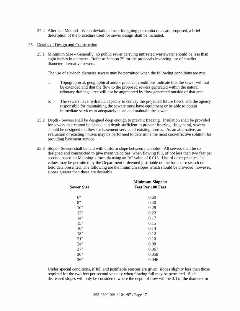
25.3 Slope - Sewers shall be laid with uniform slope between manholes. All sewers shall be sodesigned and constructed to give mean velocities, when flowing full, of not less than two feet persecond, based on Manning’s formula using an "n" value of 0.013. Use of other practical "n"values may be permitted by the Department if deemed justifiable on the basis of research orfield data presented. The following are the minimum slopes which should be provided; however,slopes greater than these are desirable.
Minimum Slope inSewer Size Feet Per 100 Feet
6" 0.60 8" 0.40 10" 0.28 12" 0.22 14" 0.17 15" 0.15 16" 0.14 18" 0.12 21" 0.10 24" 0.08 27" 0.067 30" 0.058 36" 0.046
Under special conditions, if full and justifiable reasons are given, slopes slightly less than thoserequired for the two feet per second velocity when flowing full may be permitted. Suchdecreased slopes will only be considered where the depth of flow will be 0.3 of the diameter or
362-0300-001 / 10/1/97 / Page 18
greater for maximum monthly average flow. Whenever such decreased slopes are selected, theengineer must furnish with his report computations of the depths of flow in such pipes atminimum hourly, maximum monthly average and peak instantaneous rates of flow. The sewerdiameter and slope shall be selected to obtain the greatest practical velocities to minimizesettling problems. It is recognized that such decreased slopes may cause additional sewermaintenance expense.
25.31 Sewers on Steep Slopes - Sewers on 20 percent slope or greater shall be anchoredsecurely with concrete anchors or equal. It will be the responsibility of the designengineer to prepare a detailed anchor design. The anchors shall be spaced as follows:
Not over 36 feet center to center on grades 20 percent and up to 35 percent.
Not over 24 feet center to center on grades 35 percent and up to 50 percent.
Not over 16 feet center to center on grades 50 percent and over.
25.4 Alignment - Normally sewers 24 inches or less in diameter shall be laid with straight alignmentbetween manholes. The alignment shall be checked by either using a laser beam or lamping.
On curved roadways where straight alignment would be difficult and expensive, curvilinearalignment may be considered for sewers larger than 24 inches. Only simple curves will bepermitted. The radius of curvature shall be at least 100 feet. Manholes shall be installed ateach end of the curved section, and the distance between manholes should not exceed 250 feet;however, longer distances up to 400 feet may be approved, especially on a larger size sewer, solong as the interior angle of the curve between manholes does not exceed 90 degrees.Compression or chemically welded joints shall be used, and joint deflection or pull shall notexceed the maximum permissible under ASTM pipe or joint standards C-425, C-447 andC-361. Chemically welded pipe joint specifications D-2680 or equivalent shall apply. Thespecifications shall contain provisions for sewer cleaning equipment which will adequatelymaintain the flow capacity of the sewers and will prevent damage during the cleaning operation.
25.5 Increasing Size - When a smaller sewer joins a larger one, the invert of the larger sewer shouldbe lowered sufficiently to maintain the same energy gradient. An approximate method ofsecuring these results is to place the 0.8 depth point of both sewers at the same elevations.
25.6 High Velocity Protection - Where velocities greater than 15 feet per second are attained at peakinstantaneous flow condition, special provision shall be made to protect the sewer againstdisplacement by erosion and shock.
25.7 Materials - Any generally accepted material for sewers will be given consideration, but thematerial selected should be adapted to local conditions, such as character of industrial wastes,possibility of septicity, soil characteristics, exceptionally heavy external loadings, abrasion, andsimilar problems.
Suitable couplings complying with ASTM specifications shall be used for joining dissimilarmaterials. The leakage limitations on these joints shall be in accordance with Section 25.9.
All sewers shall be designed to prevent damage from super-imposed loads. Proper allowance forloads on the sewer shall be made because of the width and depth of the trench. When standardstrength sewer pipe is not sufficient, the additional strength needed may be obtained by usingextra strength pipe or by special construction.
362-0300-001 / 10/1/97 / Page 19
For new pipe materials for which ASTM standards have not been established, the designengineer shall provide complete pipe specifications and installation specifications developed onthe basis of criteria adequately documented and certified in writing by the pipe manufacturer tobe satisfactory for the specific detailed plans.
25.8 Installation
25.81 Standards
Installation specifications shall contain appropriate requirements based on the criteria,standards and requirements established by the industry in its technical publications.Requirements shall be set forth in the specifications for the pipe and methods of beddingand backfilling thereof so as not to damage the pipe or its joints, impede cleaningoperations and future tapping, create excessive sidefill pressures or ovalation of the pipe,or seriously impair flow capacity.
25.82 Trenching
a. Trenching shall comply with appropriate OSHA regulations. The width of thetrench shall be ample to allow the pipe to be laid and joined properly and to allowthe backfill to be placed and compacted as needed. The trench sides shall be kept asnearly vertical as possible. When wider trenches are dug, appropriate bedding classand pipe strength shall be used.
b. Ledge rock, boulders and large stones shall be removed to provide a minimumclearance of four inches below and on each side of all pipes.
25.83 Pipe Embedment
The pipe embedment area consists of bedding, haunching and initial backfill zones.Bedding is the material on which a pipe or conduit is supported. The bedding zone is thearea of the bedding underneath the pipe or conduit in a trench. The haunching zone isthe area between the bottom of the pipe and the spring line (1/2 the diameter of the pipe)in a trench. The initial backfill zone is the area between the spring line of the pipe andextending some distance above the top of the pipe in a trench. The following describesthe embedment material to be used in installing rigid or flexible pipes.
a. Bedding material shall be classes A, B or C as described in ASTM C12 or WPCFMOP No. 9 (ASCE MOP No. 37) for all rigid pipes, provided the proper strengthpipe is used with the specified bedding to support the anticipated load. The samebedding material or other stone aggregate shall be used in the haunching and initialbackfill zones such that a minimum cover of six inches above the pipe is provided.
b. Bedding material shall be classes I, II or III as described in ASTM D2321- for allflexible pipes, provided the proper strength pipe is used with the specified bedding tosupport the anticipated load. The same bedding material or other stone aggregateshall be used in the haunching and initial backfill zones such that a minimum coverof six inches above the pipe is provided.
25.84 Remaining Backfill
a. Suitable material removed from trench excavation except where other material isspecified may be used in backfilling the remainder of the trench. Debris, frozen
362-0300-001 / 10/1/97 / Page 20
material, large clods or stones, organic matter or other unsuitable materials shall notbe used as backfill within two feet of the top of the pipe.
b. Pipe embedment and remaining backfill shall be placed in such a manner as not todisturb the alignment of the pipe.
25.85 Deflection Test
a. Deflection tests shall be performed on all flexible pipe. Deflection tests forcomposite pipes, such as truss pipe, shall be performed if the design engineer deemsit necessary. The test shall be run not less than 30 days after final backfill has beenplaced.
b. No pipe shall exceed a deflection of five percent.
c. The rigid ball or mandrel used for the deflection test shall have a diameter not lessthan 95 percent of the base inside diameter or average inside diameter of the pipe,depending on which is specified in the ASTM Specification, including the appendix,to which the pipe is manufactured. The pipe shall be measured in compliance withASTM D 2122 Standard Test Method of Determining Dimensions of ThermoplasticPipe and Fittings. The test shall be performed without mechanical pulling devices.
25.9 Joints and Leakage Tests
25.91 Joints
The installation of joints and the materials used shall be included in the specifications.Sewer joints shall be designed to minimize infiltration and to prevent the entrance ofroots throughout the life of the system.
25.92 Leakage Tests
Leakage tests shall be specified. This may include appropriate water or low pressure airtesting. The testing methods selected should take into consideration the range ingroundwater elevations during the test and anticipated during the design life of the sewer.
The leakage exfiltration or infiltration shall not exceed 100 gallons per inch of pipediameter per mile per day for any section of the system. An exfiltration or infiltrationtest shall be performed with a minimum positive head of two feet.
The air test shall, as a minimum, conform to the test procedure described in ASTM C-828-86 for clay pipe, ASTM C 924 for concrete pipe, and for other materials’ testprocedures as recommended by the manufacturer and approved by the Department.
26. Manholes
26.1 Location - Manholes shall be installed at all changes in grade and size, changes in alignment forsewers less than 24” in diameter, at all intersections and at distances not greater than 400 feetfor sewers 15 inches or less and 500 feet for sewers 18 inches to 30 inches. Greater spacingmay be permitted in larger lines where adequate cleaning equipment for such spacing isprovided. Cleanouts may be used only for special conditions and shall not be substituted formanholes nor installed at the end of laterals greater than 150 feet in length.
362-0300-001 / 10/1/97 / Page 21
The location of manholes in streams should be avoided. All manholes subject to flooding shallbe protected with watertight covers.
26.2 Drop Type - A drop pipe should be provided for the sewer entering a manhole at an elevation of24 inches or more above the manhole invert. Where the difference in elevation between theincoming sewer and the manhole invert is less than 24 inches, the invert should be filleted toprevent solids deposition.
Drop manholes should be constructed as an outside drop connection. Inside drop connections(when necessary) shall be secured to the interior wall of the manhole and provide access forcleaning.
Due to the unequal earth pressure that would result from the backfilling operation in the vicinityof the manhole and to support the drop pipe, the entire outside drop connection shall be encasedin concrete.
26.3 Diameter - The minimum diameter of manholes shall be 42 inches; larger diameters arepreferable. A minimum access diameter of 22 inches shall be provided.
26.4 Flow Channel - The flow channel through manholes should be made to conform in shape andslope to that of the sewers.
26.5 Watertightness - Solid watertight manhole covers are to be used whenever the manhole topsmay be flooded by street runoff or high water.
Manholes shall be of the pre-cast concrete, fiberglass, PVC, or poured-in-place concrete type.Manholes shall be waterproofed on the exterior. The specifications shall include a requirementfor inspection of manholes for watertightness prior to placing into service.
Inlet and outlet pipes shall be joined to the manhole with a gasketed, flexible, watertightconnection or any watertight connection arrangement that allows differential settlement of thepipe and manhole wall to take place.
26.6 Manhole Testing - Exfiltration tests for manholes shall be specified. These may include wateror vacuum testing. In the water test, exfiltration shall not exceed a rate of 0.019 gallons-a-dayper inch of manhole diameter per vertical foot of manhole during a continuous four hour testperiod. The vacuum testing shall be in accordance with the testing equipment manufacturer'swritten instructions and the test results compared to the manufacturer’s published vacuum testtables.
26.7 Electrical - Electrical equipment installed or used in manholes shall conform to the provisions ofSection 32.25. Electrical equipment shall not be located where it could be submerged underwater or sewage.
26.8 Venting - Gravity sewers must be adequately vented through holes in manhole covers wheninfiltration/inflow is not a problem, or through other provisions.
27. Sewers in Relation to Streams
27.1 Location of Sewers in Streams - The top of all sewers entering or crossing streams shall be at asufficient depth below the natural bottom of the stream bed to protect the sewer line. In general,one foot of cover should be provided where the sewer is located in rock and three feet of cover(including concrete encasement) in other material; in major streams, more than three feet of
362-0300-001 / 10/1/97 / Page 22
cover may be required. Less cover will be considered only if the proposed sewer crossing willnot interfere with future improvements to the stream channel. Reasons for requesting less covershould be given in the application. In paved channels, the top of the sewer line should be placedbelow the bottom of the channel pavement. Sewer outfalls, headwalls, manholes, gateboxes orother structures shall be so located that they do not interfere with the free discharge of floodflows of the stream. Sewers located along streams shall be located outside of the streambed andsufficiently removed therefrom to provide for future possible stream widening and to preventpollution by siltation during construction.
27.2 Construction - Sewers entering or crossing streams shall be constructed of cast or ductile ironpipe with mechanical joints or concrete encasement around other types of pipes so that they willremain watertight and free from changes in alignment or grade. Sewer systems shall bedesigned to minimize the number of stream crossings. The stream crossings shall be designed tocross the stream as nearly perpendicular to the stream flow as possible. The constructionmethods that will minimize siltation shall be employed. Upon completion of construction, thestream shall be returned as near as possible to its original condition. The stream banks shall beseeded, planted or other erosion prevention methods employed to prevent erosion. Theconsulting engineer shall specify the specific method or methods to be employed in theconstruction of the sewers in or near the stream to control siltation.
27.3 Siltation and Erosion Control - During construction of sewerage projects, the contractor shall beprohibited by clauses in the specifications from unnecessary disturbing or uprooting trees andvegetation along the stream bank and in the vicinity of the stream, dumping of soil and debrisinto streams and/or on banks of streams, changing course of the stream without encroachmentpermit, leaving cofferdams in streams, leaving temporary stream crossings for equipment,operating equipment in the stream, or pumping silt-laden water into the stream.
27.4 Inverted Siphons - Inverted siphons should have two or more barrels, with a minimum pipe sizeof six inches, and shall be provided with necessary appurtenances for convenient flushingmaintenance; the manholes shall have adequate clearance for rodding; and in general, sufficienthead shall be provided and pipe sizes selected to secure velocities of at least three feet persecond at maximum monthly average flows conveyed by the sewers. The inlet and outlet detailsshall be arranged so that the normal flow is diverted to one barrel, so that either barrel may becut out of service for cleaning.
27.5 Aerial Crossings - Support shall be provided for all joints in pipes utilized for aerial crossings.The supports shall be designed to prevent frost heave, overturning and settlement.
Precautions against freezing, such as insulation and increased slope, shall be provided.Expansion joints shall be provided between above-ground and below-ground sewers.
For aerial stream crossings, the impact of flood waters and debris shall be considered. Thebottom of the pipe should be placed no lower than the elevation of the 50-year flood.
28. Protection of Water Supplies
28.1 Water Supply Interconnections - There shall be no physical connection between a public orprivate water supply system and a sewer, or appurtenance thereto, which would permit thepassage of any sewage or polluted water into the potable water supply. No water pipe shallpass through or come in contact with any part of a sewer manhole.
28.2 Relation to Waterworks Structures - While no general statement can be made to cover allconditions, it is generally recognized that sewers shall be kept remote from public water supply
362-0300-001 / 10/1/97 / Page 23
wells or other water supply sources and structures. When sewers are proposed in the vicinity ofany water supply facilities, requirements in the state’s Water Supply Manual should be used toconfirm acceptable isolation distances. In general, sanitary sewers should be located at least100 feet from public water supply sources and 50 feet from private water supply sources unlessthe sanitary lines are encased in concrete or constructed of ductile iron pipe with mechanicaljoints or equivalent.
28.3 Relation to Water Mains
28.31 Horizontal Separation - Whenever possible, sewers should be laid at least 10 feet,horizontally, from any existing or proposed water mains. Should local conditionsprevent a lateral separation of 10 feet, a sewer may be laid closer than 10 feet to a watermain if:
a. it is laid in a separate trench; or if
b. it is laid in the same trench, with the water main located at one side of a bench ofundisturbed earth; and if
c. in either case the elevation of the top (crown) of the sewer is at least 18 inches belowthe bottom (invert) of the water main.
28.32 Vertical Separation - Whenever sewers must cross under water mains, the sewer shall belaid at such an elevation that the top of the sewer is at least 18 inches below the bottomof the water main. When the elevation of the sewer cannot be varied to meet the aboverequirements, the water main shall be relocated to provide this separation, for a distanceof 10 feet extending on each side of the sewer. If possible, one full length of water mainshould be centered over the sewer so that both joints will be as far from the sewer aspossible. The water main should be constructed of slip-on or mechanical-joint cast-ironpipe, PVC pipe, or pre-stressed concrete cylinder pipe and the sewer constructed ofmechanical-joint cast-iron pipe for any portion within 10 feet of the water main. Bothservices shall be pressure tested to assure watertightness prior to backfilling. Where lessthan an 18" vertical separation exists between the water and sewer line, the sewer linemay be concrete encased 10 feet on either side of the water main.
If possible, sewers crossing water mains shall be constructed so that the sewer joints willbe equidistant and as far as possible from the water main joints. Where a water maincrosses under a sewer, adequate structural support shall be provided for the sewer toprevent damage to the water main.
29. Alternative Sewer Systems
As an alternative to a conventional gravity sewer system, the use of such systems as small diameter,variable grade, vacuum, pressure sewers and STEP (septic tank effluent pumping) systems may beconsidered in designing the wastewater conveyance systems. The selection of conveyance systemsshould be based on both monetary and nonmonetary (e.g., environmental, social, institutional)considerations. This section includes design guidelines/standards for pressure sewer system.Proposals received for the use of any other alternative conveyance systems will be reviewed on theirmerits on a case-by-case basis. In general, the Department will use the consultant’s analysis andrecommendations, manufacturer's literature, experience with similar facilities and good engineeringpractice in reviewing such proposals.
362-0300-001 / 10/1/97 / Page 24
29.1 Pressure Sewer System
29.11 Application - The pressure sewer system may be considered as an alternative to aconventional gravity collection system in situations where the use of gravity sewers isnot feasible and/or cost-effective. It is expected that a pressure sewer system wouldgenerally be used in small sub-systems or areas. This system may be used underconditions such as the following:
a. Where the topography makes it difficult for the potential users to be served by agravity collection system.
b. Where groundwater conditions make it difficult to construct and maintain a gravitycollection system.
c. Where excessive rock excavation makes the gravity collection system impractical.
29.12 Design Criteria - The following considerations shall be used for the design of a pressuresewer system, including the grinder pump units or centrifugal pump units where solidsdo not present a problem.
a. Collection System
(1) No pressure sewer less than 1 1/4 inches inside diameter shall be provided.The required size shall be determined to maintain low frictional losses in thesystem and a minimum scouring velocity of two feet per second at all points inthe system.
(2) Special care shall be exercised in the hydraulic design of a pressure sewersystem which is proposed to serve ultimately more houses than those expectedto be served initially.
(3) The determination of flow in the pressure sewer system shall be made on thebasis of the maximum probable number of grinder or centrifugal pump unitsthat would be expected to run simultaneously or some other accepted methodof computing the peak sewage flow rate in the system.
(4) The pressure sewer system shall be laid out in a branched or tree configurationto avoid flow-splitting at branches which cannot be accurately predicted.
(5) The pressure sewer piping shall be installed in a depth sufficient to protectagainst freezing and damage from vehicular traffic.
(6) Although any suitable pipe material can be used, plastic pipe such asPVC SDR-26 or equivalent are considered suitable. A value of C-130 to 150is recommended to be used for plastic pipes in the Hazen-Williams formula.
(7) Clean-out connections shall be provided at distances not to exceed capacity ofavailable cleaning equipment (approximately 500-600 feet). Appropriatevalves for bypass pumping of the wastewater between cleanouts, necessaryduring the repair of the pressure sewer piping, shall be provided. Flushingcleanouts should be provided at the upstream end of every major branch.
362-0300-001 / 10/1/97 / Page 25
(8) Pressure and vacuum release valves shall be employed at appropriatelocations. Pressure sewers should be constructed on a gradually ascendingslope to minimize air binding.
(9) The pressure sewer main shall be color taped or coded to distinguish betweensanitary sewer and water main, and the direction of flow should be indicatedon all pressure sewers inside the buildings.
(10) Current requirements for protection of water supplies, as outlined inSection 28, shall be followed.
(11) Pressure sewer system operating pressures in general shall not exceed a rangeof 40 to 60 psi for any appreciable period of time.
(12) Thorough pressure testing of all lines, fittings, etc. shall be made prior tostart-up.
(13) Details of construction shall be clearly stated in the drawings and/orspecifications.
b. Grinder Pump Units
(1) The minimum net storage capacity of the grinder pump unit shall beapproximately 50 gallons. The grinder pump tank should be able toaccommodate normal peak flows and emergency storage during a short powerfailure.
(2) If grinder pump units are replacing an existing on-lot system, the existingsystem should be retained for holding wastewater during an extensive powerfailure. An emergency overflow should be provided from the grinder pumptank to the emergency holding tank.
(3) The grinder pump shall have the characteristics which will continue toproduce flows of at least eight gpm under all conditions.
(4) Check and shut-off valves shall be employed to isolate the grinder pump unitfrom the house service line and the pressure laterals.
(5) Appropriate high water and overflow detection devices such as visual and/oraudio alarm shall be provided. The grinder pump control panel shall contain aseparate control circuit and breaker for the alarms.
(6) Provisions shall be made to insure that the grinder pump operates under powerload fluctuations and contains integral protection against back siphonage andover pressure.
(7) The grinder pump unit shall be capable of reducing any material in thewastewater which enters the grinder unit to such size that the material will
362-0300-001 / 10/1/97 / Page 26
pass through the pump unit and pressure sewer without plugging or clogging.No screens or other devices requiring regular maintenance shall be used toprevent trashy material from entering the grinder pump.
(8) At least one stand-by grinder pump unit for each 50 units or fraction thereofshall be provided for emergency replacement.
(9) If the grinder pump unit is installed outside the residence, provision must bemade for access, as well as protection, from weather and vandalism. Insideinstallations shall be quiet and free from electrical and/or health hazards. Allinstallations shall be certified by nationally recognized independent testinglaboratories, such as the Underwriter’s Laboratories, Inc. and the NationalSanitation Foundation.
(10) The grinder pump unit must be capable of being removed without dewateringthe collection tank.
c. Centrifugal Pump Units
(1) As an alternative to using the grinder pump unit, a centrifugal pump may beused in conjunction with an existing septic tank or other pump tank.Specifically designed centrifugal pumps with cutters may be used in lieu ofgrinder pump for pumping raw wastewater.
(2) All conditions applicable to the grinder pump unit as stated in Section 29.12b,which can be utilized with the centrifugal pump unit, shall be considered.
29.13 Operation, Maintenance and Service - Grinder pump units must be serviceable andreplaceable under wet conditions without electric hazard to the repair personnel.Provisions should also be made to avoid interruption of sewer service due to mechanicalor power failure.
a. Ownership and Repair Services - Ownership and responsibilities for repairand maintenance of the pressure sewers and grinder pump units shall beclearly defined and established prior to the approval of any installation. Thepressure sewer system shall be owned, maintained and operated by amunicipal or other governmental body or private company. The grinder orcentrifugal pump unit may be owned and operated by a private concern orindividual. However, the pump unit should be maintained through amaintenance agreement, by the owner of the pressure sewer system. Privateownership and maintenance will be accepted as a viable alternative. The partymaintaining the units shall have full repair service capability on short notice.
362-0300-001 / 10/1/97 / Page 27
30. WASTEWATER PUMPING STATIONS
31. General
31.1 Flooding - Wastewater pumping station structures and electrical and mechanical equipmentshall be protected from physical damage by the 100-year flood. Wastewater pumping stationsshould remain fully operational and accessible during the 25-year flood. Applicable regulationsof State and Federal agencies regarding flood plain obstructions shall be followed.
31.2 Accessibility - The pumping stations shall be readily accessible by maintenance vehicles duringall weather conditions. It is recommended that pump station areas be fenced and that hatches topump stations be locked, especially for those pump stations located in remote areas. Thefacility should be located off the traffic way of streets and alleys.
31.3 Grit - Where it is necessary to pump wastewater prior to grit removal, the design of the wet welland pump station piping shall receive special consideration to avoid operational problems fromthe accumulation of grit.
31.4 When an existing pumping station is to be modified, the specifications shall include provisionsfor adequate pumping capacity during the construction period.
31.5 Types - Wastewater pumping stations in general use fall into four types: wet well/dry well,submersible, suction lift and screw pump. Wet well/dry well, submersible and suction lift pumpstations are described under Sections 32, 33 and 34, respectively.
32. Wet and Dry Well Pump Stations
32.1 Structures
32.11 Separation - Dry wells, including their superstructure, shall be completely separatedfrom the wet well. A dehumidifier is recommended for moisture control.
32.12 Equipment Removal - Provisions shall be made to facilitate removing pumps, motors,and other mechanical and electrical equipment.
32.13 Access - Suitable and safe means of access for persons wearing self-contained breathingapparatus shall be provided for both dry and wet wells.
For built-in-place pump stations, a stairway with rest landings should be provided at verticalintervals not to exceed 12 feet. For factory-built pump stations over 15 feet deep, arigidly fixed landing should be provided at vertical intervals not to exceed 10 feet.Where a landing is used, a rigidly fixed barrier should be provided to prevent anindividual from falling past the intermediate landing to a lower level. A manlift orelevator may be used in lieu of landings in a factory-built station, provided emergencyaccess is included in the design.
32.14 Construction Material - Due consideration shall be given to the selection of materialsbecause of the presence of hydrogen sulfide and other corrosive gases, greases, oils, andother constituents frequently present in wastewater.
32.15 Buoyancy - Where high groundwater conditions are anticipated, buoyancy of thewastewater pumping station structures shall be considered and, if necessary, adequateprovisions shall be made for their protection.
362-0300-001 / 10/1/97 / Page 28
32.2 Pumps and Pneumatic Ejectors
32.21 Multiple Units - At least two pumps or pneumatic ejectors shall be provided. Aminimum of three pumps should be provided for stations designed to handle maximummonthly average flows of greater than one mgd.
Where only two units are provided, they shall be of the same capacity. Each shall becapable of handling peak instantaneous flows. Where three or more units are provided,they should be designed to fit actual flow conditions and must be of such capacity thatwith any one unit out of service, the remaining units will have capacity to handle peakinstantaneous flows.
32.22 Protection Against Clogging - Pumps handling sanitary or combined wastewater shall bepreceded by one or more of the screening devices such as a manually cleaned bar screen,mechanically cleaned bar screen, comminutor, or coarse bar rack to protect the pumpsfrom clogging or damage. Where a manually and/or mechanically cleaned bar screen isused, refer to Section 51.131 for appropriate bar spacing. Where a manually cleanedbar screen or coarse bar rack is provided, convenient facilities must be provided forhandling screenings.
32.23 Except where grinder pumps are used, pumps shall be capable of passing spheres of atleast three inches in diameter, and pump suction and discharge piping shall be at leastfour inches in diameter.
32.24 Priming - The pump shall be so placed that under normal operating conditions, it willoperate under a positive suction head, except as specified in Section 33 for suction liftpump stations.
32.25 Electrical Equipment - Electrical systems and components in wet wells (e.g., motors,lights, cables, conduits, switchboxes, control circuits, etc.) shall comply with theNational Electrical Code requirements for Class I, Division 1, Group D, locations. Inaddition, equipment located in the wet well shall be suitable for use under corrosiveconditions. Each flexible cable shall be provided with a water-tight seal and separatestrain relief. A fused disconnect switch located above ground shall be provided for allpumping stations. When such equipment is exposed to weather, it shall meet therequirements of weather proof equipment. NEMA 3R or 4.
Electrical systems and components in dry well shall comply with the National ElectricalCode requirements for Class I, Division 1, Group D locations, if the structuralconfiguration or piping arrangement could lead to a situation where hazardousconcentrations of flammable gases or vapors "could reasonably be present".
A 110 volt power receptacle to facilitate maintenance should be provided inside thecontrol panel for lift stations that have control panels outdoors. Ground faultinterruption protection shall be provided for all outdoor outlets.
32.26 Intake - Each pump should have an individual intake. Wet well design should be such asto avoid turbulence near the intake and to prevent vortex formation. Intake pipingshould be as straight and short as possible.
32.27 Dry Well Dewatering - A sump pump equipped with dual check valves shall be providedin the dry wells to remove leakage or drainage with the discharge above the high waterlevel of the wet well. Water ejectors connected to a potable water supply will not be
362-0300-001 / 10/1/97 / Page 29
approved. All floor and walkway surfaces should have an adequate slope to a point ofdrainage. Pump seal water shall be piped to the sump.
32.28 Pumping Rates - The pumps and controls of main pumping stations, and especiallypumping stations operated as part of the treatment facility, should be selected to operateat varying delivery rates. Such pump stations should be designed to deliver as uniformflow as practicable in order to minimize hydraulic surges.
32.29 Quick disconnect provisions should be considered in wet well type pumping stations forease in replacing pumps.
32.3 Controls
32.31 Type - Control systems shall be of the air bubbler type, the encapsulated float type, thesonic detector type, or the flow measuring type. Float tube control systems on existingstations being upgraded may be approved, provided that related electrical equipmentcomplies with the National Electrical Code requirements for Class I, Division 1,Group D locations.
32.32 Location - The control system shall be located away from the turbulence of incomingflow and pump suction. Float tubes in dry wells shall extend high enough to preventoverflow. Provisions should be made to automatically alternate the pumps in use.
32.4 Valves - Suitable shutoff valves shall be placed on the suction line of dry pit pumps.
Suitable shutoff and check valves shall be placed on the discharge line of each pump (except onscrew pumps). The check valve shall be located between the shutoff valve and the pump. Checkvalves shall be suitable for the material being handled and shall be placed on the horizontalportion of discharge piping. Check valves shall not be placed on the vertical portion ofdischarge piping except that check valves may be approved on vertical risers when plans andspecifications require a specific valve which is designed and is advertised by the manufactureras suitable for raw wastewater on a vertical riser (e.g. ball check valves). Valves shall becapable of withstanding normal pressure and water hammer. Motorized slow closing plugvalves are acceptable.
All shutoff and check valves shall be operable from the floor level and accessible formaintenance. Outside levers are recommended on swing check valves.
Where limited pump backspin will not damage the pump and low discharge head conditionsexist, short individual force mains for each pump may be considered in lieu of discharge valves.
Valves shall not be located in the wet well.
32.5 Wet Wells
32.51 Divided Wells - Consideration should be given to dividing the wet well into multiplesections, properly interconnected, to facilitate repairs and cleaning.
32.52 Size - The wet well size and control setting shall be appropriate to avoid heat buildup inthe pump motor due to frequent starting and to avoid septic conditions due to excessivedetention time. The effective capacity (e.g., capacity between working levels) of the wetwell shall generally provide a holding period not to exceed 10 minutes for the maximummonthly average flow. Where tributary flow distance is short, a holding period not toexceed 30 minutes for the maximum monthly average flow should be considered.
362-0300-001 / 10/1/97 / Page 30
32.53 Floor Slope - The wet well floor shall have a minimum slope of one horizontal toone vertical (1:1) to the hopper bottom. The horizontal area of the hopper bottom shallbe not greater than necessary for proper installation and functioning of the inlet.
32.6 Ventilation - Ventilation shall be provided for all pump stations. Where the dry well is below theground surface, mechanical ventilation is required. If screens or mechanical equipmentrequiring maintenance or inspection are located in the wet well, permanently installed ventilationis required. There shall be no interconnection between the wet well and dry well ventilationsystems.
In dry wells over 15 feet deep, multiple inlets and outlets are desirable. Dampers should not beused on exhaust or fresh air ducts, and fine screens or other obstructions in air ducts should beavoided to prevent clogging.
Switches for operation of ventilation equipment should be marked and located conveniently. Allintermittently operated ventilating equipment shall be interconnected with the respective pitlighting system. Consideration should be given for the use of automatic controls whereintermittent operation is used. The manual lighting ventilation switch shall override theautomatic controls. The fan wheel should be fabricated from non-sparking material. Automaticheating and/or dehumidification equipment shall be provided in all dry wells. The electricalequipment and components shall meet the requirements in Section 32.25.
32.61 Wet Wells - Ventilation may be either continuous or intermittent. Ventilation, ifcontinuous, shall provide at least 12 complete air changes per hour; if intermittent, atleast 30 complete air changes per hour. Air shall be forced into the wet well bymechanical means rather than exhausted from the wet well.
32.62 Dry Wells - Ventilation may be either continuous or intermittent. Ventilation, ifcontinuous, shall provide at least six complete air changes per hour; if intermittent, atleast 30 complete air changes per hour.
32.7 Flow Measurement - Suitable devices for measuring wastewater flow shall be consideredat all pumping stations.
32.8 Water Supply - There shall be no physical connection between any potable water supplyand a wastewater pumping station which, under any conditions, might causecontamination of the potable water supply. If a potable water supply is brought to thestation, it should comply with conditions stipulated under Section 46.2.
33. Suction Lift Pump Stations
Suction lift pumps shall be of the self-priming or vacuum-priming type and shall meet the applicablerequirements under Section 32. Suction lift pump stations using dynamic suction lifts exceeding thelimits outlined in the following sections may be approved by the Department upon submission offactory certification of pump performance and detailed calculations indicating satisfactoryperformance under the proposed operating conditions. The pump equipment compartment shall beabove grade or offset and shall be effectively isolated from the wet well to prevent the humid orcorrosive atmosphere from entering the equipment compartment. Wet well access shall not be throughthe equipment compartment. Valving shall not be located in the wet well.
362-0300-001 / 10/1/97 / Page 31
33.1 Self-Priming Pumps - Self-priming pumps shall be capable of rapid priming and repriming atthe "lead pump on" elevation. Such self-priming and repriming shall be accomplishedautomatically under design operating conditions. Suction piping should not exceed the size ofthe pump suction and shall not exceed 25 feet in total length. Priming lift at the "lead pump on"elevation shall include a safety factor of at least four feet from the maximum allowable priminglift for the specific equipment at design operating conditions. The combined total of dynamicsuction lift at the "pump off" elevation and required net positive suction head at designoperating conditions shall not exceed 22 feet.
33.2 Vacuum Priming Pumps - Vacuum priming pump stations shall be equipped with dual vacuumpumps capable of automatically and completely removing air from the suction lift pump. Thevacuum pumps shall be adequately protected from damage due to wastewater. The combinedtotal of dynamic suction lift at the "pump off" elevation and required net positive suction head atdesign operating conditions shall not exceed 22 feet.
34. Submersible Pump Stations
Submersible pump stations shall meet the applicable requirements under Section 32, except asmodified in this Section.
34.1 Construction - Submersible pumps and motors shall be designed specifically for raw wastewateruse and shall meet the requirements of the National Electrical Code for such units. An effectivemethod to detect shaft seal failure should be provided.
34.2 Pump Removal - Submersible pumps shall be readily removable and replaceable withoutdewatering the wet well or disconnecting any piping in the wet well.
34.3 Electrical
a. Electrical supply, control and alarm circuits shall be designed to provide strain relief andto allow disconnection at a junction box located or accessible from outside the wet well.Terminals and connectors shall be protected from corrosion by location outside of thewet well or by water-tight seals. If located outside, weatherproof equipment shall beused.
b. The motor control center shall be protected by a conduit seal or other appropriate sealingmethod meeting the requirements of the National Electrical Code for Class I, Division 1,Group D locations.
c. The pump motor shall meet the requirements of the National Electrical Code for Class I,Division 1, Group D locations.
d. Pump motor power cords shall be designed for flexibility and serviceability underconditions of extra hard usage. Ground fault interruption protection shall be used todeenergize the circuit in the event of any failure in the electrical integrity of the cable.
e. Power cord terminal fittings shall be provided with strain relief appurtenances and shallbe designed to facilitate field connection.
34.4 Valves - Valves required under Section 32.4 shall be located in a separate valve pit.Accumulated water shall be drained to the wet well or to the soil. If the valve pit is drained tothe wet well, the discharge point shall be above the high water level of the wet well.
362-0300-001 / 10/1/97 / Page 32
34.5 Operation - Submersible pumps shall be capable of unsubmerged operation without damage orreduction of service capability, or positive provisions (e.g., back-up controls) shall be made toassure submergence.
35. Alarm Systems
Alarm systems shall be provided for pumping stations. The alarm shall be activated in cases of powerfailure, pump failure, use of the lag pump, unauthorized entry, high water, or any cause of pumpstation malfunction. Pumping station alarms should be telemetered, including identification of thealarm condition, to a municipal facility that is manned 24 hours a day. If such a facility is notavailable, the alarm shall be telemetered to city offices during normal working hours and to the homeof the person(s) in responsible charge of the pump station during off-duty hours. Audio-visual alarmsystems with a self-contained power may be acceptable in some cases in lieu of the telemeteringsystem outlined above, depending upon location, station holding capacity, and inspection frequency.
36. Emergency Operation
Pumping stations and collection systems shall be designed to prevent or minimize bypassing of rawwastewater. For use during possible periods of extensive power outages, mandatory power reductionsor storm events, consideration should be given to providing a controlled, high-level wet well overflowto supplement alarm systems and emergency power generation in order to prevent backup ofwastewater into basements, or other discharges which may cause severe adverse impacts on publicinterests, including public health and property damage. Where a high-level overflow is utilized,consideration shall also be given to the installation of storage detention tanks or basins, which shall bemade to drain to the station wet well. Where such overflows affect public water supplies, shell fishproduction or waters used for culinary or food processing purposes, a storage detention basin or tankshall be provided having a two-hour detention capacity at the anticipated overflow rate.
36.1 Overflow Prevention Methods - A satisfactory method shall be provided to prevent or minimizeoverflows. The following methods should be evaluated on an individual basis. The choiceshould be based on least cost and least operation problems of the methods providing anacceptable degree of reliability.
36.11 Storage Capacity - Storage capacity, including trunk sewers for retention of wet weatherflows, should be evaluated. Storage basins must be designed to drain back into the wetwell or collection system after the flow recedes.
36.12 In-Place or Portable Pump - An in-place or portable pump driven by an internalcombustion engine meeting the requirements of Section 36.2 below, capable of pumpingfrom the wet well to the discharge side of the station, should be considered.
36.13 Independent Public Utility Sources - Independent public utility sources or engine-drivengenerating equipment meeting the requirements of Section 36.2 below should beconsidered.
36.2 Equipment Requirements
36.21 General - The following general requirements shall apply to all internal combustionengines used to drive auxiliary pumps, service pumps through special drives or electricalgenerating equipment.
362-0300-001 / 10/1/97 / Page 33
36.211 Engine Protection - The engine must be protected from operating conditions thatwould result in damage to equipment. Unless continuous manual supervision isplanned, protective equipment shall be capable of shutting down the engine,activating an alarm on site and as provided in Section 35. Protective equipmentshall monitor for conditions of low oil pressure and overheating, except oilpressure monitoring will not be required for engines with splash lubrication.
36.212 Size - The engine shall have adequate rated power to start and continuouslyoperate all connected loads.
36.213 Fuel Type - Reliability and ease of starting, especially during cold weatherconditions, should be considered in the selection of the type of fuel.
36.214 Engine Ventilation - The engine shall be located above grade with adequateventilation of fuel vapors and exhaust gases.
36.215 Routine Start-up - All emergency equipment shall be provided with instructionsindicating the need for regular starting and running of such units at full loads.
36.216 Protection of Equipment - Emergency equipment shall be protected from damageat the restoration of regular electrical power.
36.22 Engine-Driven Pumping Equipment - Where permanently installed or portableengine-driven pumps are used, the following requirements, in addition to generalrequirements, shall apply.
36.221 Pump(s) Capacity - Engine driven pump(s) shall meet the design pumpingrequirements unless storage capacity is available for flows in excess of pumpcapacity. Pumps shall be designed for anticipated operating conditions,including suction lift, if applicable.
36.222 Operation - The engine and pump shall be equipped to provide automatic start-up and operation of pumping equipment unless manual start-up and operation isjustified. Provisions shall also be made for manual start-up. Where manualstart-up and operation is justified, storage capacity and alarm system must meetthe requirements of Section 36.223.
36.223 Portable Pumping Equipment - Where part or all of the engine- driven pumpingequipment is portable, sufficient storage capacity with alarm system shall beprovided to allow time for detection of pump station failure and transportationand hookup of the portable equipment. A riser from the force main with quickconnect coupling and appropriate valving shall be provided to hook up portablepumps.
36.23 Engine-Driven Generating Equipment - Where permanently installed or portableengine-driven generating equipment is used, the following requirements, inaddition to general requirements, shall apply.
36.231 Generating Capacity - Generating unit size shall be adequate to provide powerfor pump motor starting current and for lighting, ventilation, and other auxiliaryequipment necessary for safety and proper operation of the lift station.
The operation of only one pump during periods of auxiliary power supply mustbe justified. Such a justification may be made on the basis of maximum
362-0300-001 / 10/1/97 / Page 34
anticipated flows relative to single pump capacity, anticipated length of poweroutage, and storage capacity.
Special sequencing controls shall be provided to start pump motors unless thegenerating equipment has the capacity to start all pumps simultaneously withauxiliary equipment operating.
36.232 Operation - Provisions shall be made for automatic and manual start-up andload transfer. The generator must be protected from operating conditions thatwould result in damage to equipment. Provisions should be considered to allowthe engine to start and stabilize at operating speed before assuming the load.Where manual start-up and transfer is justified, storage capacity must meet therequirements in Section 36.233.
36.233 Portable Generating Equipment - Where portable generating equipment ormanual transfer is provided, sufficient storage capacity to allow time fordetection of pump station failure and transportation and connection ofgenerating equipment, shall be provided. The use of special electricalconnections and double throw switches are recommended for connectingportable generating equipment.
37. Instructions and Equipment
Wastewater pumping stations and their operators should be supplied with a complete set ofoperational instructions, including emergency procedures, maintenance schedules, special tools, andsuch spare parts as may be necessary.
38. Force Mains
38.1 Velocity - At maximum monthly average flow, a velocity of at least two feet per second shall bemaintained.
38.2 Air and Vacuum Relief Valve - An air relief valve shall be placed at high points in the forcemain to prevent air locking. Vacuum relief valves may be necessary to relieve negative pressureon force mains. The force main configuration and head conditions should be evaluated as to theneed for and placement of vacuum relief valves.
38.3 Termination - Force mains should enter the gravity sewer system at a point not more thantwo feet above the flow line of the receiving manhole.
38.4 Pipe and Design Pressure - Pipe and joints shall be equal to water main strength materialssuitable for design conditions. The force main, reaction blocking and station piping shall bedesigned to withstand water hammer pressures and associated cyclic reversal stresses that areexpected with the cycling of wastewater pump stations. Surge protection chambers should beevaluated.
38.5 Special Construction - Force main construction near streams shall meet applicable requirementsof Section 27.
38.6 Design Friction Losses - Friction losses through force mains shall be based on theHazen-Williams formula or other acceptable method. When the Hazen-Williams formula isused, the following values for "C" shall be used for design.
362-0300-001 / 10/1/97 / Page 35
Unlined iron or steel - 100PVC - 130-150All other - 120
When initially installed, force mains will have a significantly higher "C" factor. The higher "C" factorshould be considered only in calculating maximum power requirements.
38.7 Minimum Size - No public force main shall be less than four inches in diameter, except wheregrinding facilities are used.
38.8 Separation from Water Mains - There shall be at least a 10-foot horizontal separation betweenwater mains and sanitary sewer force mains. Force mains crossing water mains shall be laid toprovide a minimum vertical distance of 18 inches between the outside of the force main and theoutside of the water main. This shall be the case where the water main is either above or belowthe force main. At crossings, if possible, one full length of water pipe shall be located so bothjoints will be as far from the force main as possible. Special structural support for the watermain and force main may be required.
38.9 Identification of Force Mains and Leakage Testing - Where force mains are constructed ofmaterial which might cause the force main to be confused with potable water mains, the forcemain should be appropriately identified.
Leakage tests, including testing methods and leakage limits, shall be specified in contractdocuments.
39. RESERVED FOR FUTURE USE
362-0300-001 / 10/1/97 / Page 36
40. WASTEWATER TREATMENT PLANTS
41. General
41.1 Design Information - The engineer should confer with the Department before proceeding withthe design of detailed plans for wastewater treatment plants. Plants should be designed to serveabout 20 years projected population from the initiation of design. Deferred construction ofthose units which can be easily increased in capacity is a consideration to minimize the initialconstruction costs.
41.2 Plant Location - In general, to avoid local objections, a wastewater treatment plant site shouldbe as far as practicable from any present built-up area or any area which will probably be builtup within a reasonable future period. It is recommended that the treatment plant be at least250 feet from an occupied dwelling or recreational area. The direction of prevailing windsshould be considered when selecting the plant site. If a critical location must be used, specialconsideration must be given to the design and type of plant provided. Space should be providedto allow for plant expansion in the event of a population expansion or requirement for additionaltreatment. Compatibility of treatment process with the present and planned future land use,including noise, potential odors, air quality, and anticipated sludge processing and disposaltechniques should be considered.
Where a site must be used which is critical with respect to these items, appropriate measuresshall be taken to minimize adverse impacts.
Local soil characteristics, geology, hydrology, and topography should be considered.
41.3 Flood Protection - The treatment plant structures, electrical and mechanical equipment shall beprotected from physical damage by the 100-year flood. Treatment plant should remain fullyoperational and accessible during the 25-year flood. This applies to new construction and toexisting facilities undergoing major modification.
41.4 Climate Protection - At treatment plants designed to be operated during the winter months, awalk-in housing with heaters shall be provided for equipment such as blowers, chlorinators,chemical feeders, and controls which may be adversely affected by low temperatures. Specialdesign consideration shall also be given to treatment units which, based on practical operatingexperience, will operationally be adversely affected by cold weather.
42. Quality of Effluent
The wastewater treatment plant shall be designed to meet all NPDES Part I Permit effluentlimitations.
43. Design
43.1 Type of Treatment - Careful consideration should be given to the type of treatment beforemaking a final decision. A few of the important factors which would influence the selection ofthe type of treatment are: the location and topography of the plant site, the effect of industrialwastes likely to be encountered, the effect of cold temperatures on treatment efficiency,operating costs, the probable type of supervision and operation which the plant will need, andpresent and future effluent requirements.
362-0300-001 / 10/1/97 / Page 37
Other considerations, such as space available for future plant expansion, ultimate disposal orutilization of sludge, energy requirements, process complexity, environmental impact on presentand future adjacent land use, and construction in floodplains and wetlands should be taken intoaccount.
43.2 New Processes, Methods and Equipment - See Section 9.4.
43.3 Industrial Wastes - Wherever applicable, information on the expected physical, chemical, andbiological characteristics of industrial wastewater should be obtained in order to determine itstreatability characteristics and acceptability for discharge into the sewerage system (e.g. todetermine what pretreatment requirements may be appropriate). It may be necessary to conducta pilot plant study of the treatability of the wastewater to establish appropriate designparameters.
43.4 Design Flow - The wastewater received at the treatment plant is made up of domesticwastewater, industrial wastewater, and the infiltration/inflow within the sewer system.Domestic wastewater consists of flow from residential, commercial, institutional, andrecreational establishments. Industrial wastewater includes wastewater generated by employeesand any process or cooling water discharged to the sewer system.
The design flow of a treatment plant is a generalized term reflective of all of the abovecomponents, which indicates the flow conditions, up to which the facility will be capable ofproviding a predetermined level of treatment. The treatment plant shall be designed toaccommodate the design flow conditions while meeting the NPDES (Part I) and Water QualityManagement (Part II) permit requirements, and also to avoid potential overload situations asdefined in Chapter 94 of the Department’s rules and regulations.
The treatment plant/unit process design necessitates the use of a set of specific design flowparameters to accurately express the different design flow conditions which will occur due to:(a) diurnal variations (e.g. morning flush), (b) non-domestic source variations (e.g. industrialprocess flows), (c) seasonal domestic variations (e.g. vacation homes and recreational facilities),and (d) seasonal weather-induced variations (e.g., infiltration/inflow). The individual unitprocess design standards contained in this manual describe the appropriate design flowparameters to be used in designing a particular unit. The name, general definitions, and typicalapplication of the commonly used design flow parameters are given below.
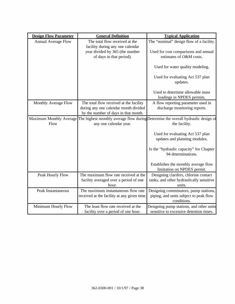
362-0300-001 / 10/1/97 / Page 38
Design Flow Parameter General Definition Typical ApplicationAnnual Average Flow The total flow received at the
facility during any one calendaryear divided by 365 (the number
of days in that period).
The “nominal” design flow of a facility.
Used for cost comparisons and annualestimates of O&M costs.
Used for water quality modeling.
Used for evaluating Act 537 planupdates.
Used to determine allowable massloadings in NPDES permits.
Monthly Average Flow The total flow received at the facilityduring any one calendar month dividedby the number of days in that month.
A flow reporting parameter used indischarge monitoring reports.
Maximum Monthly AverageFlow
The highest monthly average flow duringany one calendar year.
Determine the overall hydraulic design ofthe facility.
Used for evaluating Act 537 planupdates and planning modules.
Is the “hydraulic capacity” for Chapter94 determinations.
Establishes the monthly average flowlimitation on NPDES permit.
Peak Hourly Flow The maximum flow rate received at thefacility averaged over a period of one
hour.
Designing clarifers, chlorine contacttanks, and other hydraulically sensitive
units.Peak Instantaneous The maximum instantaneous flow rate
received at the facility at any given time.Designing comminutors, pump stations,piping, and units subject to peak flow
conditions.Minimum Hourly Flow The least flow rate received at the
facility over a period of one hour.Designing pump stations, and other units
sensitive to excessive detention times.
362-0300-001 / 10/1/97 / Page 39
43.41 New Systems - For municipal systems and subdivisions of over 150 homes, the designannual average flow shall be based on 100 gallons per capita per day, with a 24-hourrunoff period. The design annual average flow for plants serving less than 150 homesmay be based on 75 gallons per capita per day, with a 16-hour runoff period. Theseflow figures include an allowance for infiltration.
Any deviation from these values should be based on actual data for water consumptionand projected or anticipated flow due to infiltration (during high groundwaterconditions). The pipe manufacturer’s recommendations and/or actual infiltration valuesobtained in the field with the use of a similar kind of pipe having similar field conditionsmay be used to establish the projected flow due to infiltration.
The design flow for institutional and recreational establishments should be based on thedesign data in Section 43.51 of the manual and/or water consumption data (actual orestimated).
Estimates of design wastewater flows for industrial/commercial dischargers must takeinto account the expected amounts of process wastewater, sanitary wastewater, andcooling water which will be discharged into the sewerage system. Such informationshould be obtained directly from the owner/operator of the industrial/commercialestablishment.
43.42 Existing Systems - When an existing treatment plant is expanded/upgraded, the volumeand strength of existing flows shall be determined. As a minimum, the existing plant’spast five years of data (if available) shall be reviewed, and a design engineer’s reportsummarizing the monthly flows, loadings and corresponding performance of variousunits and/or plant as a whole should be prepared for at least three years’ representativedata (exclude the data pertaining to abnormal rain or drought conditions). The reportshould serve as the basis for development of the design flow and organic loadings basedon the past as well as projected future conditions.
The design flow for the proposed plant expansion/upgrade should be based on themaximum monthly average flow derived from historical data, plus the additionalprojected maximum monthly average flow due to future flow contributions during thedesign period of the plant. The projected flow should include domestic wastewater flow,industrial wastewater flow, and infiltration/inflow within the sewer system based onfuture conditions.
The submission of a Water Quality Management Part II Permit application must beaccompanied with a design engineer’s report. The report must include informationconcerning the basis of design flow, the proposed and existing unit processes, the designand operational standards applied to each of the process units, and the source ofinformation used as the basis of the design standards.
When an existing sewer system (currently not served by a treatment facility) is to beserved by a new or modified treatment facility, the volume and strength of existing flowsshall be determined. Flow monitoring of the sewer system should be conducted to obtainsuch information as maximum monthly flow, maximum monthly loading, peak hourlyflow, etc., necessary to design various treatment units utilizing the appropriate flowparameters as described in the manual or other design literature for each treatment unit.
362-0300-001 / 10/1/97 / Page 40
43.43 Flow Equalization - Facilities for equalization of flows shall be considered at alltreatment plants in order to provide flexibility in plant operation and facilitate optimalplant performance. This will better insure that the desired effluent quality will beconsistently obtained.
43.5 Organic Design - The organic loading received at the treatment plant is made up of domesticloading and industrial loading. Domestic loading consists of loadings from residential,commercial, institutional, and recreational establishments and includes all loadings except fromindustries. The design organic loading is the rated/permitted organic capacity of the treatmentplant to provide a predetermined level of treatment. The treatment plant shall be designed tomeet the NPDES as well as Part II permit requirements and avoid potential overload as definedunder Chapter 94 of the Department’s rules and regulations. The plant should be designed totreat the maximum monthly average organic loading. The shock effects of high concentrationsand peak diurnal flows for short periods of time on the treatment process, particularly for smalltreatment plants, should be considered.
Biological Oxygen Demand (BOD) as used in this manual is defined as the amount of oxygenrequired to stabilize biodegradable organic matter under aerobic conditions within a five-dayperiod.
43.51 New Systems - The following design data should be used in the design of wastewatertreatment plants to serve new sewerage systems unless information is submitted tojustify different values. The most recent U.S. Census data should be used to developpopulation projections.
For municipalities:
Flow 100 gpd/cap, including infiltration
BOD 0.17 lb/day/cap (0.22 lb/day/cap may be usedwhen garbage grinders are prevalent)
Suspended Solids 0.20 lb/day/cap (0.25 lb/day/cap may be usedwhen garbage grinders are prevalent)
Runoff Period 24 hours
Note: Add appropriate allowance for industrial, commercial, institutional andrecreational contributions. Also, any contributions from such sources as septictank cleaners, landfill leachates, etc. should be added.
For subdivisions of not over 150 houses and mobile home spaces:
Flow 75 gpd/cap, including infiltration
BOD 0.17 lb/day/cap (0.22 lb/day/cap may be used when garbage grinders are prevalent)
Suspended Solids 0.20 lb/day/cap (0.25 lb/day/cap may be used when garbage grinders are prevalent)
Runoff Period 16 hours
362-0300-001 / 10/1/97 / Page 41
For public schools:
Toilet Rooms only:
Flow 7 gpd/cap
BOD 0.04 lb/day/cap
For kitchen add 3 gpd/cap and 0.04 lb/day/cap BOD allowance ifappropriate
For gym add 3 gpd/cap and 0.02 lb/day/cap BOD allowance ifappropriate
Runoff Period 8 hours
For boarding schools:
Flow 75 gpd/cap
BOD 0.17 lb/day/cap
Runoff Period 16 hours
For factories:
Flow 35 gpd/cap
BOD 0.085 lb/day/cap
Runoff Period Length of shift
Note: The facility shall be designed for largest shift.
For camps:
Flow 60 gpd/cap
BOD 0.12 lb/day/cap
Runoff Period 16 hours
For hospitals and similar institutions:
Flow 150-250 gpd/cap
BOD 0.17 lb/day/cap plus proper allowance for extra facilities
Runoff Period 12-24 hours
43.511 Design by Analogy - Data from similar municipalities or subdivisions may beutilized in the case of new systems; however, the designer must be able to clearly
362-0300-001 / 10/1/97 / Page 42
show to the Department the similarities between the existing municipalities orsubdivisions (whose data are to be used) and the proposed facility. The designershould submit a narrative outlining the rationale for the data from similarmunicipalities or subdivisions.
43.52 Existing Systems - When an existing treatment plant is to be expanded/upgraded, thedesign organic loading shall be based on the maximum monthly average organic load thefacility is required to treat during the design life of the facility. The design organicloading is based on the maximum monthly average organic loading derived fromhistorical data plus the additional projected maximum monthly average organic loadingdue to future load contributions. The design engineer’s report (as described underSection 43.42) should serve as the basis for the development of the design organicloading. The determination should take into account both dry weather and wet weatherconditions.
43.6 Conduits - All piping and channels should be designed to carry the peak instantaneous flows.The incoming sewer should be designed for unrestricted flow. Bottom corners of the channelsmust be filleted. Conduits shall be designed to avoid creation of pockets and corners wheresolids can accumulate. Suitable gates should be placed in channels to seal off unused sectionswhich might accumulate solids. The use of shear gates, stop gates, or stop planks is permittedwhere they can be used in place of gate valves or sluice gates. Corrosion resistant materialsshall be used for these control gates. All piping and channels shall be accessible for cleaningout settled solids.
43.7 Arrangement of Units - All treatment units and their components should be arranged for greatestoperation and maintenance convenience, flexibility, economy, continuity of effluent quality, andfor facilitation of the installation of future units. Cold weather operation should also beconsidered when arranging the treatment units and their component parts to utilize, wherefeasible, solar radiant heat and natural protection from wind and weather.
43.8 Flow Division Control - Flow division control facilities shall be provided, as necessary, toinsure organic and hydraulic loading control to plant process units and shall be designed foreasy operator access for change, observation, and maintenance. The use of head boxesequipped with adjustable sharp-crested weirs or similar devices is recommended. The use ofvalves for flow splitting is not recommended. Appropriate flow measurement shall beincorporated in the flow division control design.
44. Plant Details
44.1 Installation of Mechanical Equipment - The specifications should be so written that theinstallation and initial operation of major items of mechanical equipment will be supervised by arepresentative of the manufacturer.
44.2 Unit Bypasses - Properly located and arranged bypass structures and piping shall be providedso that each unit of the plant can be removed from service independently. The bypass designshall facilitate plant operation during unit maintenance and emergency repair so as to minimizedeterioration of effluent quality and insure rapid process recovery upon return to normaloperational mode. The system with two or more units and involving open basins (such assettling basins, aeration basins, disinfectant contact basins) shall not be required to haveprovisions for bypassing if the peak instantaneous wastewater flows can be handledhydraulically with the largest flow unit out of service.
362-0300-001 / 10/1/97 / Page 43
44.21 Unit Bypass During Construction - Final plan documents shall include bypassrequirements as deemed necessary by the Department to avoid unacceptable temporarywater quality degradation.
44.3 Drains - Means shall be provided to dewater each unit to an appropriate point in the process.Due consideration shall be given to the possible need for hydrostatic pressure relief devices toprevent flotation of structures. Pipes subject to clogging shall be provided with means formechanical cleaning or flushing.
44.4 Construction Materials - Due consideration should be given to the selection of materials whichare to be used in a wastewater treatment plant because of the possible presence of hydrogensulfide and other corrosive gases, greases, oils, and similar constituents frequently present in thewastewater. This is particularly important in the selection of metals and paints. Contactbetween dissimilar metals should be avoided to minimize galvanic action.
44.5 Painting - The use of paints containing lead or mercury should be avoided. In order to facilitateidentification of piping, particularly in the large plants, it is suggested that the different lines becolor coded. The following color scheme is recommended for purposes of standardization:
Raw sludge line - brown with black bandsSludge recirculation suction line - brown with yellow bandsSludge draw off line - brown with orange bandsSludge gas line - orange (or red)Natural gas line - orange (or red) with black bandsNonpotable water line - blue with black bandsPotable water line - blueChlorine line - yellowWastewater line - grayCompressed air line - greenWater lines for heating digesters or buildings - blue with a six-inch red band spaced 30 inchesapart
The contents and direction of flow shall be stenciled on the piping in a contrasting color.
44.6 Operating Equipment - A complete set of tools, accessories, and spare parts necessary for theplant operator’s use shall be provided. Readily accessible storage space and work benchfacilities shall be provided, and consideration should be given to provisions of a garage area forlarge equipment, maintenance, and repair.
44.7 Erosion Control During Construction - Effective site erosion control shall be provided duringconstruction. A soil erosion and sedimentation control plan shall be included in the constructiondocuments.
44.8 Grading and Landscaping - Upon completion of the plant, the ground should be graded andsodded or seeded. All weather walkways should be provided for access to all units. Wherepossible, steep slopes should be avoided to prevent erosion. Surface water shall not bepermitted to drain into any unit. Particular care shall be taken to protect trickling filter beds,sludge beds, and intermittent sand filters from storm water runoff. Provisions should be madefor landscaping, particularly when a plant must be located near residential areas.
45. Plant Outfalls
362-0300-001 / 10/1/97 / Page 44
45.1 Discharge Impact Control - The outfall sewer shall be designed to discharge to the receivingstream in a manner which will assure adequate dispersion and prevent nuisance conditions. Theoutfall and/or headwall and stream crossings associated with the sewerage applications arepermitted under the Water Quality Management Part II Permit. Consideration should also begiven to the following:
a. Preference for free fall or submerged discharge at the site selected.
b. Utilization of cascade aeration of effluent discharge to increase dissolved oxygen.
c. Limited or complete across stream dispersion, as needed, to protect aquatic lifemovement and growth in the immediate reaches of the receiving stream.
d. Headwalls may be used where adequate dispersion is obtained without carrying theoutfall into the stream.
e. Requirements of Section 27.1 concerning an outfall extended into the stream.
45.2 Protection and Maintenance - The outfall sewer shall be so constructed and protected againstthe effects of flood water, tide, ice, or other hazards as to reasonably insure its structuralstability and freedom from blockage. A manhole should be provided at the shore end of allgravity sewers extending into the receiving waters. Hazards to navigation shall be considered indesigning outfall sewers.
45.3 Sampling Provisions - All outfalls shall be designed so that a sample of the effluent can beobtained at a point after the final treatment process and before discharge to or mixing with thereceiving waters.
46. Power Facilities
46.1 Emergency Power Facilities - All plants shall be provided with an alternate source of electricpower or pumping capability to allow continuity of operation during power failures. Methodsof providing alternate sources include:
a. The connection of at least two separate and independent public utility sources such assubstations. A power line from each substation will be required, unless documentation isreceived and approved by the Department, verifying that duplicate lines are notnecessary to minimize water quality violations.
b. Portable or inplace internal combustion engine equipment which will generate electricalor mechanical energy.
c. Portable pumping equipment when only emergency pumping is required.
For more specific information refer to Section 36 - Emergency Operation for pumping stations.
46.11 Standby Equipment - Standby generating capacity normally is not required for aerationequipment used in the activated sludge process. In cases where a history of long-term(four hours or more) power outages have occurred, auxiliary power for minimumaeration of the activated sludge will be required. Full power generating capacity and/orother special waste treatment facilities may be required by the Department for wastedischarges to certain critical stream segments. Examples of critical stream segments are
362-0300-001 / 10/1/97 / Page 45
ones where there are discharges above: (a) a bathing beach, (b) a public water supplysource that does not have chlorination facilities and/or (c) other similar situations.
46.12 Disinfection - Continuous disinfection, where required, shall be provided during allpower outages.
46.2 Water Supply
46.21 General - An adequate supply of potable water under pressure should be provided foruse in the laboratory and for general cleanliness around the plant. No piping or otherconnections shall exist in any part of the treatment plant which, under any conditions,might cause the contamination of a potable water supply. The chemical quality shouldbe checked for suitability for its intended uses such as for heat exchangers, chlorinators,etc.
46.22 Direct Connections - Potable water from a municipal or separate supply may be useddirectly at points above grade for the following hot and cold supplies:
a. Lavatoryb. Water closetc. Laboratory sink (with vacuum breaker)d. Showere. Drinking fountainf. Eye wash fountaing. Safety shower
Hot water for any of the above units shall not be taken directly from a boiler used for supplyinghot water to a sludge heat exchanger or digester heating coils.
46.23 Indirect Connections - Where a potable water supply is to be used for any purpose in aplant other than those listed in Section 46.22, a break tank, pressure pump and pressuretank shall be provided. Water shall be discharged to the break tank through an air gap atleast six inches above the maximum flood line or the spill line of the tank, whichever ishigher. Vacuum breaker or reduced backflow preventer may be used in lieu of breaktank, pressure pump, and pressure tank.
Under some conditions, the cost differential for an air gap separation may be very highwhen compared to a mechanical back-flow prevention device or it may be extremelydifficult to provide an air gap separation. Under these conditions, a Reduced PressureZone Device (RPZD) may be selected for cross connection control. Such device shouldconform to AWWA standards C-506. RPZD provides protection from back-flow due toboth back-pressure or back-siphonage. Malfunctioning of the RPZD is indicated by adischarge of the water from the relief port. This factor is an important factor over thedouble check valve assembly which shall not be approved, except as provided for underSection 46.22.
A sign shall be permanently posted at every hose bib, faucet, hydrant, or sill cocklocated on the water system beyond the break tank to indicate that the water is not safefor drinking.
46.24 Separate Potable Water Supply - Where it is not possible to provide potable water froma public water supply, a separate well may be provided. Location and construction ofthe well should comply with requirements of the state and local regulations.
362-0300-001 / 10/1/97 / Page 46
Requirements governing the use of the supply are those contained in Section 46.22 andSection 46.23.
46.25 Separate Non-Potable Water Supply - Where a separate non-potable water supply is tobe provided, a break tank will not be necessary, but all system outlets shall be postedwith a permanent sign indicating the water is not safe for drinking.
46.3 Sanitary Facilities - Toilets, showers, lavatories, and lockers shall be provided in sufficientnumbers and at convenient locations to serve the expected plant personnel. Such facilities maynot be necessary at plants where a part-time operator is employed.
46.4 Laboratory - All treatment works should include a laboratory for making the necessaryanalytical determinations and operating control tests. Isolation is required to render thelaboratory reasonably free from the adverse effects of noise, heat, vibration, and dustcontamination.
46.5 Floor Slopes - Floor surfaces shall be sloped adequately to a point of drainage.
46.6 Stairways - Stairways shall be installed in lieu of ladders for access to units requiring inspectionand maintenance, such as digesters, trickling filters, aeration tanks, clarifiers, tertiary filters,etc. Stairways should be installed with consideration to facilitate carrying samples, tools, etc.All risers in a stairway should be of equal height.
46.7 Flow Measurement - Flow measurement facilities shall be provided at all plants. Indicating,totalizing, and recording flow measurement devices shall be provided for all plants withmaximum monthly average flow of 0.1 mgd or greater. Flow measurement facilities for lagoonsystems shall not be less than pump calibration time clocks or calibrated flume.
Flow measurement devices should be selected for reliability and accuracy. The effect ofchanges in backwater elevations due to intermittent cleaning of screens should be considered inlocations of flow measurement equipment.
46.8 Septage and Holding Tank Waste - Facilities should be provided at municipal treatment plantsfor the acceptance and safe and sanitary handling of liquid organic waste material such as septicand/or holding tank pumpings delivered to the site by tank truck or other similar means. Suchfacilities should be designed to discharge the waste into the treatment plant during off-peak flowhours at a rate which does not adversely affect the operation of the treatment units and theefficiency of the treatment plant.
47. Safety
Adequate provisions shall be made to effectively protect the operator and visitors from hazards. Thefollowing shall be provided to fulfill the particular needs of each plant:
a. Enclosure of the plant site with a fence designed to discourage the entrance of unauthorizedpersons and animals.
b. Installation of hand rails and guards around tanks elevated less than four feet, trenches, pits,stairwells, and other hazardous structures. Grating over areas of the treatment units wheremaintenance is required.
c. Provisions of first aid equipment.
362-0300-001 / 10/1/97 / Page 47
d. Posting of "No Smoking" signs in hazardous areas.
e. Provisions of protective clothing and equipment such as air packs, goggles, gloves, hard hats,safety harnesses, etc.
f. Provisions of portable blower and sufficient hose.
g. Portable lighting equipment approved by the U.S. Bureau of Mines for use in confined spaces.
h. Appropriately placed warning signs for slippery areas, non-potable water fixtures, low headclearance areas, open service manhole, hazardous chemical storage areas, flammable fuelstorage areas, etc.
i. The provisions of Section 32.6, with respect to ventilation which may apply to wastewatertreatment plants shall be followed.
j. Provisions for local lockout on stop motor controls.
k. Provisions for a handicapped person to gain access to laboratory, administrative, and otherbuildings.
47.1 Hazardous Chemical Handling
Underground storage facilities for chemicals such as alum or ferric chloride or fuels shall beconstructed in accordance with EPA regulations and the State Storage Tank and SpillPrevention Act (Act 32) for underground storage tanks for both fuels and hazardous materials.
47.11 Containment Materials - The materials utilized for storage, piping, valves, pumping,metering, splash guards, etc., shall be specially selected considering the physical andchemical characteristics of each hazardous or corrosive chemical.
47.12 Secondary Containment - Chemical storage areas shall be enclosed in dikes or curbswhich will contain the stored volume until it can be safely transferred to alternate storageor released to the wastewater at controlled rates which will not damage facilities, inhibitthe treatment processes or contribute the stream pollution. Liquid polymer should besimilarly contained to reduce areas with slippery floors, especially to protect travelways.Non-slip floor surfaces are desirable in polymer- handling areas.
47.13 Eye Wash Fountains and Safety Showers - Eye wash fountains and safety showersutilizing potable water shall be provided in the laboratory and on each floor level orwork location involving hazardous or corrosive chemical storage, mixing (or slaking),pumping, metering or transportation unloading. These facilities are to be as close aspracticable to possible chemical exposure sites and are to be fully useful during allweather conditions.
The eye wash fountains shall be supplied with water of moderate temperature (50o-90oF.), separate from the hot water supply, suitable to provide 15 to 30 minutes ofcontinuous washing of the eyes.
The emergency showers shall be capable of discharging 30 to 50 gpm of water atmoderate temperature at pressures of 20 to 50 psi. The eye wash fountains and showersshall be no more than 25 feet from points of hazardous chemical exposure.

362-0300-001 / 10/1/97 / Page 48
47.14 Splash Guards - All pumps or feeders for hazardous or corrosive chemicals shall haveguards which will effectively prevent spray of chemicals into space occupied bypersonnel. The splash guards are in addition to guards to prevent injury from moving orrotating machinery parts.
47.15 Piping Labeling, Coupling Guards, Location - All piping containing or transportingcorrosive or hazardous chemicals shall be identified with labels every 10 feet and with atleast two labels in each room, closet, or pipe channel. Color coding may also be used,but is not an adequate substitute for labeling. All connections (flanged or other type),except adjacent to storage or feeder areas, shall have guards which will direct anyleakage away from space occupied by personnel. Pipes containing hazardous orcorrosive chemicals should not be located above shoulder level except where continuousdrip collection trays and coupling guards will eliminate chemical spray or dripping ontopersonnel.
47.16 Protective Clothing and Equipment - The following items of protective clothing orequipment shall be available and utilized for all operations or procedures where their usewill minimize injury hazard to personnel:
a. Respirators, air supply type recommended for protection against chlorine.
b. Chemical workers’ goggles or other suitable goggles. (Safety glasses areinsufficient.)
c. Face masks or shields for use over goggles.
d. Rubber gloves.
e. Rubber aprons with leg straps.
f. Rubber boots. (Leather and wool clothing should be avoided near caustics).
g. Safety harness and line.
47.17 Warning System and Signs - Facilities shall be provided for automatic shutdown ofpumps and sounding of alarms when failure occurs in a pressurized chemical dischargeline. Warning signs requiring use of goggles shall be located near chemical unloadingstations, pumps, and other points of frequent hazard.
47.18 Dust Collection - Dust collection equipment shall be provided to protect personnel fromdusts injurious to the lungs or skin and to prevent polymer dust from settling onwalkways. The latter is to minimize slick floors which result when a polymer-coveredfloor becomes wet.
47.19 Container Identification - The identification and hazard warning data included onshipping containers, when received, shall appear on all containers (regardless of size ortype) used to store, carry or use as a hazardous substance. Wastewater and sludgesample containers should be adequately labeled. Below is a suitable label for awastewater sample:
RAW WASTEWATER
Sample point no. _______________
362-0300-001 / 10/1/97 / Page 49
Contains Harmful Bacteria.
May contain hazardous or toxic material.
Do not drink or swallow.
Avoid contact with openings or breaks in the skin.
48. Operation
The wastewater treatment plant must be operated by competent persons and be under theresponsibility of an operator certified by the State Board for Certification of Sewage Treatment Plantand Waterworks Operators to ensure efficiency of operation and protection of the waters of theCommonwealth.
49. RESERVED FOR THE FUTURE
362-0300-001 / 10/1/97 / Page 50
50. PRETREATMENT
51. Screening Devices
In order to protect the plant from reduced efficiency and/or physical damage, all plants shall beequipped with one or more of the screening devices such as manually cleaned bar screen, mechanicallycleaned bar screen, comminutor, or coarse bar racks. Selection of a particular device will be governedby its intended purpose and the circumstances as detailed in this chapter. Provisions for odor controlshould be investigated and provided whenever a potential problem may develop.
51.1 Bar Screens
51.11 Specific Provisions - A manually cleaned bar screen shall be required as the solescreening device or as an emergency bypass to the mechanically cleaned bar screen orcomminutor.
51.12 Location
51.121 Indoors - Screening devices installed in a building where other equipment oroffices are located should be in a separate portion of the building which isaccessible only through a separate outside entrance.
51.122 Outdoors - Screening devices installed outside shall be protected from freezing.
51.123 Access - Screening areas shall be provided with stairway access, adequatelighting and ventilation, and a convenient and adequate means for removing thescreenings and maintaining equipment.
51.13 Design Considerations
51.131 Bar Spacing - Clear openings between bars for manually cleaned screens shouldbe no less than one inch. Clear openings for mechanically cleaned screensshould be no less than 5/8 of an inch and no greater than 1 3/4 inches.
51.132 Slope - Manually cleaned screens should be placed on a slope of 30 to 45degrees to the horizontal.
51.133 Velocities - At maximum monthly average flow and peak instantaneous flowconditions, approach velocities should be no less than 1.25 feet per second toprevent settling, and no greater than 3.0 feet per second to prevent forcingmaterial through the openings.
51.134 Channels - Dual channels shall be provided and equipped with the necessarygates to isolate flow from any screening unit. Provisions shall also be made tofacilitate dewatering each unit. The channel preceding and following the screenshall be shaped to eliminate stranding and settling of solids.
51.135 Invert - The screen channel invert should be three to six inches below the invertof the incoming sewer.
51.136 Flow Distribution - Entrance channels should be designed to provide equal anduniform distribution of flow to the screens.
362-0300-001 / 10/1/97 / Page 51
51.137 Screenings Removal and Disposal - A convenient and adequate means forremoving screenings shall be provided. Hoisting or lifting equipment may benecessary depending on the depth of pit and amount of screenings or equipmentto be lifted.
Facilities must be provided for handling and storage of screenings. Screeningsshall be disposed at the Department approved facility. Separate grinding ofscreenings and return to the wastewater flow is unacceptable. Manually cleanedscreening facilities should include an accessible platform from which theoperator may rake screenings easily and safely. Suitable drainage facilities shallbe provided both for the platform and for storage areas.
51.14 Access and Ventilation
Screens located in pits more than four feet deep shall be provided with stairway access.Access ladders are acceptable for pits less than four feet deep, in lieu of stairways.Screening devices, installed in a building where other equipment or offices are located,shall be isolated from the rest of the building, be provided with separate outsideentrances, and be provided with separate and independent fresh air supply.
Fresh air shall be forced into enclosed screening device areas or in open pits more thanfour feet deep. Dampers should not be used on exhaust or fresh air ducts, and finescreens or other obstructions should be avoided to prevent clogging. Where continuousventilation is required, at least 12 complete air changes per hour shall be provided.Where continuous ventilation would cause excessive heat loss, intermittent ventilation ofat least 30 complete air changes per hour shall be provided when workmen enter thearea.
Switches for operation of ventilation equipment should be marked and locatedconveniently. All intermittently operated ventilation equipment shall be interconnectedwith the respective pit lighting system. The fan wheel should be fabricated from non-sparking material.
51.15 Safety
51.151 Railings and Gratings - Channels for manually cleaned screen shall be protectedby guard railings and deck gratings, with adequate provisions for removal oropening to facilitate raking.
Channels for mechanically cleaned screen shall be protected by guard railingsand deck gratings, with adequate provisions for access to facilitate maintenanceand repair.
51.152 Mechanical Devices - Mechanically cleaned screens shall have adequateremovable enclosures to protect personnel against accidental contact withmoving parts and to prevent dripping in multi-level installations.
A positive means of locking out each mechanical device shall be provided.
362-0300-001 / 10/1/97 / Page 52
51.16 Control Systems
51.161 Timing Devices - All mechanical units which are operated by timing devicesshall be provided with auxiliary controls which will set the cleaning mechanismin operation at a pre-set high water elevation. If the cleaning mechanism fails tolower the high water, a warning should be signaled.
51.162 Electrical Fixtures and Controls - Electrical fixtures and controls in screeningareas where hazardous gases may accumulate shall meet the requirements of theNational Electric Code for Class I, Division 1, Group D locations.
51.163 Manual Override - Automatic controls shall be supplemented by a manualoverride.
51.17 Auxiliary Screens - Where a single mechanically cleaned screen is used, an auxiliarymanually cleaned screen shall be provided. Where two or more mechanically cleanedscreens are used, the design shall provide for taking any unit out of service withoutsacrificing the capability to handle the peak instantaneous flow.
51.2 Fine Screens
51.21 General - Fine screens as discussed here have openings of approximately 1/16 inch. Theamount of material removed by fine screens is dependent on the waste stream beingtreated and screen opening size.
Fine screens should not be considered equivalent to primary sedimentation but may beused in lieu of primary sedimentation where subsequent treatment units are designed onthe basis of anticipated screen performance. Selection of screen capacity shouldconsider flow restriction due to retained solids, gummy materials, frequency of cleaning,and extent of cleaning. Removal of oils and greases shall be considered.
51.22 Design - Tests should be conducted to determine BOD and suspended solids removalefficiencies at the peak hydraulic and peak organic loadings.
A minimum of two fine screens shall be provided, with each unit being capable ofindependent operation. Capacity shall be provided to treat peak design flows with oneunit out of service.
Fine screens shall be preceded by a mechanically cleaned bar screen or other protectivedevice. Comminuting devices shall not be used ahead of fine screens.
51.23 Electrical Fixtures and Controls - Electrical fixtures and screening areas wherehazardous gases may accumulate shall meet the requirements of the National ElectricCode for Class I, Division 1, Group D locations.
51.24 Servicing - Hosing equipment shall be provided to facilitate cleaning. Provisions shall bemade for isolating or removing units from location for servicing.
52. Comminutors
52.1 Specific Provisions - Comminutors and/or mechanically cleaned bar screens (Barminutors) shallbe used in plants that do not have primary sedimentation. Comminutors should be provided atplants where mechanically cleaned bar screens will not be used. Consideration should be given
362-0300-001 / 10/1/97 / Page 53
to providing protection for comminutors by coarse bar racks, especially when the flow isreceived from a combined sewer system.
52.2 Location - The same requirements apply as for bar screens. Refer to Section 51.12 of thischapter.
If all the flow to the plant is received from grinder pumps, a comminutor is not needed.
52.3 Design Considerations
52.31 General - Comminutors should be located downstream of any grit removal equipment.Comminutors not preceded by grit removal equipment shall be protected by a six inchdeep gravel trap.
52.32 Size - Comminutor capacity shall be adequate to handle peak instantaneous flow.
52.33 Installation - A bypass channel with a screening device shall be provided. The use of thebypass channel should be automatic at depths of flow exceeding the design capacity ofthe comminutor or in case of comminutor failure.
52.34 Servicing - Provisions shall be made to facilitate servicing units in place and removingunits from location for servicing.
52.35 Electrical Controls and Motors - Electrical equipment in comminutor chambers wherehazardous gases may accumulate shall meet the requirements of the National ElectricCode for Class I, Division 1, Group D locations. Motors in areas not governed by thisrequirement shall be protected against accidental submergence.
52.36 Railings and Gratings - Comminutors and bypass channels shall be protected by guardrailings and deck grittings with adequate provisions for access to facilitate maintenanceand repairs.
53. Grit Removal Facilities
53.1 Specific Provisions - Grit removal facilities should be provided for all wastewater treatmentplants and are required for plants receiving wastewater from combined sewers or from sewersystems receiving substantial amounts of grit. If a plant serving a separate sewer system isdesigned without grit facilities, consideration shall be given to possible damaging effects onpumps, comminutors, other preceding equipment, and the need for additional storage capacity intreatment units where grit is likely to accumulate. The design shall include provisions for futureinstallation of grit removal facilities.
53.2 Location
53.21 General - Grit removal facilities should be located ahead of pumps and comminutingdevices. Coarse bar racks should be placed ahead of grit removal facilities.
53.22 Housed Facilities
53.221 Ventilation - Uncontaminated air shall be introduced continuously at a rate of 12air changes per hour or intermittently at a rate of 30 air changes per hour. Odorcontrol devices may also be warranted.
362-0300-001 / 10/1/97 / Page 54
53.222 Access - Adequate stairway access to above or below grade facilities shall beprovided.
53.223 Electrical - All electrical fixtures and controls in enclosed grit removal areawhere hazardous gases may accumulate shall meet the requirements of theNational Electric Code for Class I, Division 1, Group D locations.
53.224 Lighting - Adequate lighting with explosion protection shall be provided tooperate and maintain equipment.
53.23 Outside Facilities - Grit removal facilities located outside shall be protected fromfreezing.
53.3 Type and Number of Units - Plants treating wastes from combined sewers should have at leasttwo mechanically cleaned grit removal units with provisions for bypassing. A single manuallycleaned or mechanically cleaned grit chamber with bypass is acceptable for small wastewatertreatment plants serving separate sanitary sewer systems. Minimum facilities for larger plantsserving separate sanitary sewers should be at least one mechanically cleaned unit with a bypass.Facilities other than channel-type are acceptable if provided with adequate grit collection andremoval equipment and variable controls for agitation.
53.4 Design Considerations
53.41 General - The design effectiveness of a grit removal system shall be commensurate withthe requirements of the subsequent process units.
53.42 Inlet - Inlet turbulence shall be minimized in channel-type units.
53.43 Velocity and Detention - Channel-type chambers shall be designed to control velocitiesduring normal variations in flow as close as possible to one foot per second. Thedetention period shall be based on the size of particle to be removed. All grit removalfacilities should be provided with adequate automatic control devices to regulatedetention time, agitation, or air supply.
53.44 Grit Washing - The need for grit washing should be determined by the method of finalgrit disposal.
53.45 Drains - Provisions shall be made for isolating and dewatering each unit.
53.46 Water - An adequate supply of water under pressure shall be provided for cleanup.
53.47 Grit Handling - Grit removal facilities located in deep pits should be provided withmechanical equipment for hoisting or transporting grit to ground level. Impervious non-slip working surfaces with adequate drainage shall be provided for grit handling areas.Grit transporting facilities shall be provided with protection against freezing and loss ofmaterial.
53.48 Aeration - An aerated grit removal facility should be considered. This facility must havea metered and adjustable air supply.
54. Pre-aeration and Flocculation
Pre-aeration of wastewater to reduce septicity may be required in special cases.
362-0300-001 / 10/1/97 / Page 55
Flocculation of wastewater by air or mechanical agitation, with or without chemicals, is worthy ofconsideration when it is desired to reduce the strength of wastewater prior to subsequent treatment.Also, flocculation may be beneficial in pretreating wastewater containing certain industrial wastes.
54.1 Arrangement - The unit should be designed so that its removal from service will not interferewith normal operation of the remainder of the plant.
54.2 Detention Period
54.21 Coagulation - When air or mechanical agitation is used in conjunction with chemicals tocoagulate or flocculate the wastewater, the detention period should be about 30 minutesbut never less than 20 minutes at the peak hourly flow.
54.22 BOD Reduction - When air or mechanical agitation (either with or without the use ofchemicals) is used for the additional purpose of obtaining increased reduction in BOD,the detention period should be at least 45 minutes at maximum monthly average flow.
54.3 Stirring Devices
54.31 Paddles - Paddles should have a peripheral speed of 1 1/2 feet to 2 1/2 feet per second toprevent deposition of solids.
54.32 Aerators - Any of the types of equipment used for aerating activated sludge may beutilized. It shall be possible to control agitation, to obtain good mixing, and maintainself-cleaning velocities across the tank floor.
54.4 Details - Inlet and outlet devices should be designed to insure proper distribution and to preventshort-circuting. Convenient means should be provided for removing grit.
54.5 Quick Mix - At plants where there are two or more flocculation basins utilizing chemicals,provision shall be made for a quick mix of the wastewater with the chemical so that thewastewater passing to the flocculation basins will be of uniform composition. The detentionperiod provided in the quick mix chamber should be very short -- one-half to three minutes.
55. Flow Equalization
55.1 General - Use of flow equalization to reduce the variations in hydraulic and organic loadingsshall be considered at all wastewater treatment plants. When a significant portion of the plant’sflow will be from high peak flow sources (such as restaurants, schools, nursing homes andcommercial laundry), flow equalization facilities shall be provided.
55.2 Location - Equalization basins should be located downstream of pretreatment facilities such asbar screens, comminutors and grit chambers.
55.3 Type - Flow equalization can be provided by using separate equalization basins or on-linetreatment units such as aeration tanks. Equalization basins may be designed as either in-line orside-line units. Unused treatment units, such as sedimentation or aeration tanks, may be utilizedas on-line equalization basins during the early period of design life.
55.4 Size - Equalization basin capacity should be sufficient to equalize anticipated flow variations.The determination of equalization volume should be based on the wastewater flow hydrographduring wet weather conditions.
362-0300-001 / 10/1/97 / Page 56
55.5 Operation
55.51 Mixing - Aeration or mechanical equipment shall be provided to maintain adequatemixing. Corner fillets and hopper bottoms with draw-offs shall be provided to alleviatethe accumulation of sludge and grit.
55.52 Aeration - Aeration equipment shall be sufficient to maintain a minimum of one mg/l ofdissolved oxygen in the mixed equalization basin contents at all times. Air supply ratesbased on standard air (standard air is defined as air at a temperature of 68oF, a pressureof 14.7 psia, and a relative humidity of 36 percent) should be a minimum of 1.25cfm/1,000 gallons of storage capacity. The air supply should be isolated from othertreatment plant aeration requirements to facilitate process aeration control. Standardprocess aeration equipment may be utilized as a source of standby aeration.
55.53 Controls - Inlets and outlets for all equalization basin compartments shall be equippedwith accessible external valves, stop plates, weirs, or other devices to permit flowcontrol and the removal of an individual unit from service. Facilities shall also beprovided to measure and indicate liquid levels and flow rates.
55.6 Electrical - All electrical work in housed equalization basins shall meet the requirements of theNational Electric Code for Class I, Division 1, Group D locations.
55.7 Access - Suitable access shall be provided to facilitate the maintenance of equipment andcleaning.
56 through 59. RESERVED FOR FUTURE USE
362-0300-001 / 10/1/97 / Page 57
60. SETTLING
61. General - This chapter covers design guidelines for primary, intermediate and final settling tanks.
61.1 Number of Units - Multiple units capable of independent operation are desirable and shall beprovided in all plants where maximum monthly average flow exceeds 100,000 gallons per day.Plants not having multiple units shall include other provisions to assure continuity of treatment.
61.2 Arrangement - Settling tanks shall be arranged such that the criteria in Sections 43.7 and 62.7can be met.
61.3 Flow Distribution - Effective flow splitting devices and control appurtenances (e.g., valves,gates, splitter boxes, etc.) shall be provided to permit proper proportioning of flow to each unit,through the expected range of flows.
61.4 Tank Configuration - Consideration should be given to the probable flow pattern, the selectionof tank size and shape, and inlet and outlet type and location.
62. Design Considerations
62.1 Dimensions - The minimum length of flow from inlet to outlet should be 10 feet unless specialprovisions such as baffles are made to prevent short circuiting. The side water depth forprimary clarifiers shall be as shallow as practicable, but not less than seven feet. Clarifiersfollowing the activated sludge process shall have side water depths of at least 12 feet to provideadequate separation zone between the sludge blanket and the overflow weirs. Clarifiers havingless than 12 feet side water depth may be permitted for package plants, if justified, based onsuccessful operating experience. Clarifiers following fixed film reactors shall have side waterdepth of at least seven feet.
62.2 Surface Overflow Rates
62.21 Primary Settling Tanks - Surface overflow rates for primary tanks receiving wasteactivated sludge should not exceed 1,000 gallons per day per square foot at maximummonthly average flow (including recirculation flows) or 1,500 gallons per day per squarefoot for peak hourly flow (including recirculation flows).
Surface overflow rates for primary tanks not receiving waste activated sludge should notexceed 1,000 gallons per day per square foot at maximum monthly average flow(including recirculation flows) or 2,500 gallons per day per square foot for peak hourlyflow (including recirculation flows).
Settling tank sizing shall be calculated for both (average and peak hourly) flowconditions and the larger surface area determined shall be used. A BOD removal of30 percent to 35 percent will indicate efficient primary treatment. Design of treatmentunits following primary settling tanks shall take into consideration the expected BOD5removal in the primary.
62.22 Intermediate Settling Tanks - Surface overflow rates for intermediate settling tanksfollowing units of fixed film reactor processes shall not exceed 1,500 gallons per day persquare foot based on peak hourly flow.
62.23 Final Settling Tanks - Settling tests should be conducted wherever pilot study ofbiological treatment is warranted by unusual waste characteristics or treatment
362-0300-001 / 10/1/97 / Page 58
requirements. Testing shall be done where proposed loadings go beyond the limits setforth in this section.
a. Fixed Film Biological Reactors - Surface overflow rates for settling tanks followingtrickling filters or rotating biological contactors shall not exceed 1,200 gallons perday per square foot based on peak hourly flow.
b. Activated Sludge - To perform properly while producing a concentrated returnflow, activated sludge settling tanks must be designed to meet thickening as well assolids separation requirements. Since the rate of recirculation of return sludge fromthe final settling tanks to the aeration or reaeration tanks is quite high in activatedsludge processes, surface overflow rate and weir overflow rate should be adjustedfor the various processes to minimize the problems with sludge loadings, densitycurrents, inlet hydraulic turbulence, and occasional poor sludge settleability.Settling tanks in activated sludge systems must be designed not only for surfaceoverflow rates, but also for solids loading rates. The following parameters shouldbe utilized in the design of intermediate and/or final settling tanks for variousactivated sludge processes. In applying surface overflow and solids loading valuesfrom this table, sizing shall be calculated for both surface overflow and solidsloading using peak and average conditions, and the larger surface area determinedshall be used.* Consideration should be given to flow equalization.
Table
Surface Overflow Rate* Solids Loadings***(gpd/sq. ft.)*
Type of Process Average Peak** Average Peak** Conventional Activated 800 1,200 40 50
Sludge Step Aeration andContact Stabilization
Extended Aeration 500 1,000 30 50
Separate Nitrification 500 800 30 50Stage
Carbonaceous Stage of 900 1,200 45 50Sparate Stage Nitrification
* The area upstream of the inlet baffle should not be used in calculating the surface overflow rateand, furthermore, only maximum monthly average flow (i.e. excluding the return flow) should beused.
** Anticipated peak hourly flow.*** Based on mixed liquor flow - (i.e. wastewater and return sludge flow).
62.3 Inlet Structures - Inlets should be designed to dissipate the inlet velocity, to distribute the flowequally both horizontally and vertically and to prevent short-circuiting. Channels should bedesigned to maintain a velocity of at least one foot per second at one-half the maximum monthlyaverage flow. Corner pockets and dead ends shall be eliminated and corner fillets or channeling
362-0300-001 / 10/1/97 / Page 59
used where necessary. Provisions shall be made for elimination or removal of floating materialsin inlet structures.
62.4 Drains - Provisions shall be made for complete dewatering of each unit to an appropriate pointin the process. Due consideration should be given to the possible need for hydrostatic reliefdevices to prevent flotation of structures. Portable dewatering pumps may be sufficient forcomplete dewatering.
62.5 Bypasses - Design shall provide for independent removal of each settling tank unit formaintenance and repair so as to minimize deterioration of effluent quality and insure rapidprocess recovery upon return to normal operational mode. The bypass design should alsoprovide for redistribution of the plant flow to the remaining units.
62.6 Anti-flotation Devices - Adequate systems, such as hydrostatic pressure relief valves, tensionpiles, or foundation slab projections shall be incorporated in the design to prevent flotation ofdewatered tanks.
62.7 Freeboard - Walls of settling tanks shall extend at least six inches above the surrounding groundsurface and shall provide not less than 12 inches of freeboard. Where walls of settling tanks aremore than four feet above the surrounding ground surface, consideration should be given toproviding a walkway for safe access to clean the weirs and weir troughs. Additional freeboardor the use of wind screens is recommended where larger settling tanks are subject to highvelocity wind currents that would cause tank surface waves and inhibit effective scum removal.
63. Weirs
63.1 General - Overflow weirs shall be adjustable for levelling.
63.2 Location - Overflow weirs shall be located to optimize actual hydraulic detention time andminimize short-circuiting.
63.3 Design Rates - Weir loadings should not exceed 10,000 gallons per day per lineal foot atmaximum monthly average flow (excluding recycle flows) for plants designed for average flowsof one mgd or less. Higher weir loadings may be used for plants designed for larger averageflows, but should not exceed 15,000 gallons per day per lineal foot maximum monthly averageflow (excluding recycle flows). If pumping is required, weir loadings should be related to pumpdelivery rates to avoid short-circuiting.
63.4 Weir Troughs - Weir troughs shall be designed to prevent submergence at peak instantaneousflow and to maintain a velocity of at least one foot per second at one-half the maximum monthlyaverage flow.
63.5 Submerged Surfaces - The tops of troughs, beams and similar submerged construction elementsshall have a minimum slope of one horizontal to 1.4 vertical (1:1.4); the underside of suchelements should have a slope of one horizontal to one vertical (1:1) to prevent the accumulationof scum and solids.
64. Sludge and Scum Removal
64.1 Scum Removal - Effective scum collection and removal facilities, including baffling, shall beprovided for all settling tanks. The unusual characteristics of scum which may adversely affectpumping, piping, sludge handling, and disposal shall be recognized in design. Provisions may
362-0300-001 / 10/1/97 / Page 60
be made for the discharge of scum with the sludge; however, other special provisions fordisposal may be necessary.
64.2 Sludge Removal - Sludge collection and withdrawal facilities shall be so designed as to assurerapid removal of the sludge. Suction withdrawal should be provided for activated sludge plantsdesigned for reduction of the nitrogenous oxygen demand and is encouraged for those plantsdesigned for carbonaceous oxygen demand reduction.
Each settling tank shall have its own sludge withdrawal lines to insure adequate control of sludgewasting rate for each tank.
64.3 Sludge Hopper - The minimum slope of the side walls shall be one horizontal to 1.7 vertical(1:1.7). Hopper wall surfaces should be made smooth with rounded corners to aid in sludgeremoval. Hopper bottoms shall have a maximum dimension of two feet. Extra depth sludgehoppers for sludge thickening are not acceptable.
63.4 Cross-Collectors - Cross-collectors serving one or more settling tanks may be useful in place ofmultiple sludge hoppers.
64.5 Sludge Removal Piping - Each hopper shall have an individually-valved sludge withdrawal lineof at least six inches in diameter. The static head available for withdrawal of sludge shall be 30inches or greater as necessary to maintain a three feet per second velocity in the withdrawalpipe. Clearance between the end of the withdrawal line and the hopper walls shall be sufficientto prevent bridging of the sludge. Adequate provisions shall be made for rodding or back-flushing individual pipe runs. Piping shall also be provided to return secondary waste sludgefor further processing.
64.6 Sludge Removal Control - Separate settling tank sludge lines may drain to a common sludgewell. Sludge wells equipped with telescoping valves or other appropriate equipment shall beprovided for viewing, sampling, and controlling the rate of sludge withdrawal. The use of easilymaintained sight glass and sampling valves may be appropriate. A means of measuring thesludge removal rate shall be provided. An air lift type of sludge removal will not be approvedfor removal of primary sludges. Sludge pump motor control system shall include time clocksand valve activators for regulating the duration and sequencing of sludge removal.
64.7 Return Sludge Equipment
64.71 Return Sludge Rate - The minimum permissible return sludge rate of withdrawal fromthe final settling tank is a function of the concentration of suspended solids in the mixedliquor entering the settling tank, the sludge volume index of these solids, and the lengthof time these solids are retained in the settling tank. Since undue retention of solids inthe final settling tanks may be deleterious to both the aeration and sedimentation phasesof the activated sludge process, the rate of sludge return expressed as a percentage of themaximum monthly average flow of wastewater should generally be variable between thelimits set forth as follows:
362-0300-001 / 10/1/97 / Page 61
Minimum Maximum
Standard Rate 15 100Step Aeration 15 100Contact Stabilization 50 150Extended Aeration (including 50 150 oxidation ditches)Carbonaceous Stage of Separate 15 100 Stage NitrificationNitrification Stage of Separate 50 200 Stage Nitrification
The rate of sludge return shall be varied by means of variable speed motors, drives, ortimers (at small plants) to pump sludge at the above rates.
64.72 Return Sludge Pumps - If motor driven return sludge pumps are used, the maximumreturn sludge capacity shall be obtained with the largest pump out of service. A positivehead should be provided on pump suctions. Pumps should have at least three inchsuction and discharge openings.
If air lifts are used for returning sludge from each settling tank hopper, no standby unitwill be required. However, the design of the air lifts must be such that they areamenable to rapid and easy cleaning. Also, suitable standby equipment for returningsludge should be available. Air lifts shall be sized to maintain a velocity at not less thantwo feet per second when return sludge facilities are operating at minimum sludge returnrates. Provisions shall be made to prevent large objects from entering and plugging airlifts and return sludge piping.
64.73 Return Sludge Piping - Discharge piping should be designed to maintain a velocity of notless than two feet per second when return sludge facilities are operating at normal returnsludge rates. Suitable devices for observing, sampling and controlling return activatedsludge flow from each settling tank hopper shall be provided.
64.74 Waste Sludge facilities - Waste sludge control facilities should have a capacity of atleast 25 percent of the average rate of wastewater flow and function satisfactorily atrates of one-half percent of average wastewater flow or a minimum of 10 gallons perminute, whichever is larger. Means for observing, measuring, sampling, and controllingwaste activated sludge flow shall be provided. Waste sludge may be discharged to theconcentration or thickening tank, primary settling tank, sludge digestion tank, vacuumfilters, or any practical combination of these units.
64.8 Measuring Devices - Devices should be installed in all plants for indicating flow rates of rawwastewater or primary effluent, return sludge, and air to each tank unit. Measuring devices inplants designed for wastewater flows of 100,000 gpd or more should totalize and record, as wellas indicate flows. Where the design provides for all return sludge to be mixed with the rawwastewater (or primary effluent) at one location, the mixed liquor flow rate to each aeration unitshould be measured.
362-0300-001 / 10/1/97 / Page 62
65. Protective and Service Facilities
65.1 Operator Protection - All settling tanks shall be equipped to enhance safety for operators. Suchfeatures shall appropriately include machinery covers, life lines, stairways, walkways, handrails and slip resistant surfaces.
65.2 Mechanical Maintenance Access - The design shall provide for convenient and safe access toroutine maintenance items such as gear boxes, scum removal mechanism and baffles, weirs,inlet stilling baffle area, and effluent channels.
65.3 Electrical Fixtures and Controls - Electrical fixtures and controls in enclosed settling basinsshall meet the requirements of the National Electric Code for Class I, Division 1, Group Dlocations. The fixtures and controls shall be located so as to provide convenient and safe accessfor operation and maintenance. Adequate area lighting shall be provided.
66. through 69. RESERVED FOR FUTURE USE
362-0300-001 / 10/1/97 / Page 63
70. SLUDGE PROCESSING, STORAGE AND DISPOSAL
71. General - Facilities for sludge processing/storage shall be provided at all wastewater treatmentfacilities. The selection of sludge treatment/handling unit processes should be based on suchconsiderations as characteristics of the sludge, method(s) of ultimate disposal, stabilizationrequirements, cost-effectiveness, storage requirements, back-up techniques available, equipmentcomplexity, and staffing requirements.
72. Sludge Treatment Processes
The processes used for sludge treatment are grouped in the following categories:
a. Sludge thickening
b. Sludge digestion/stabilization
c. Sludge dewatering
73. Sludge Thickening
73.1 General Considerations - Sludge thickeners to reduce the volume of sludge should beconsidered. The design of thickeners (gravity, dissolved air flotation, centrifuge, and others)should consider the type and concentration of sludge, the sludge stabilization processes, themethod of ultimate sludge disposal, chemical needs, and the cost and ease of operation.Particular attention should be given to the pumping and piping of the concentrated sludge andpossible onset of anaerobic conditions. Sludge should be thickened to at least five percent solidsby weight prior to transmission to digesters.
73.2 Gravity Thickening - Both solids and hydraulic surface loading must be considered whendesigning gravity thickeners. A hydraulic loading of 400 to 800 gpd/sq. ft. and a solids loadingof five to 12 pounds/day/sq. ft. are recommended for thickeners. Solids loading is generally thecontrolling parameter and usually dictates the required surface area of the thickener. Thickenercovers to prevent odor problems shall be considered when use of lower hydraulic rates thandescribed here is proposed.
73.3 Air Flotation - The use of air flotation is limited primarily to thickening of sludges prior todewatering. Air flotation thickening is best applied to thickening waste activated sludge, and itis possible to thicken the sludge to six percent solids. A solids loading of 20 pounds/day/sq. ft.without the application of polyelectrolyte and 40 pounds/day/sq. ft. with the application ofpolyelectrolyte is recommended in the design of air flotation thickening units. The hydraulicloading should not exceed 0.8 gpm/sq. ft..
74. Anaerobic Sludge Digestion
74.1 Multiple Units - Multiple tanks or alternate methods of sludge processing shall be provided forcontinued plant operations. Facilities for sludge storage and supernatant separation in anadditional unit may be required, depending on raw sludge concentration and disposal methodsfor sludge and supernatant.
74.2 Depth - The depth of the tank should be such as to allow for the formation of a reasonable depthof supernatant liquor. A minimum sidewater depth of 20 feet is recommended.
362-0300-001 / 10/1/97 / Page 64
74.3 Maintenance Provisions - To facilitate emptying, cleaning and maintenance, the followingfeatures are desirable:
74.31 Slope - The tank bottom shall slope to drain toward the withdrawal pipe. Where thesludge is to be removed by gravity alone, the tank bottom should have a slope of fourhorizontal to one vertical (4:1). For tanks equipped with a suction mechanism forwithdrawal of sludge, a bottom slope of twelve horizontal to one vertical (12:1) orgreater is recommended.
74.32 Access Manholes - At least two 36-inch diameter access manholes should be provided inthe top of the tank in addition to the gas dome. There should be stairways to reach theaccess manholes. A separate sidewall manhole to facilitate removal of grit and sandshould be considered.
74.33 Safety - Non-sparking tools, safety lights, rubber-soled shoes, safety harnesses, gasdetectors for inflammable and toxic gases, gas masks and at least two self-containedbreathing units shall be provided for emergency use.
74.4 Sludge Inlets, Outlets, Recirculation and High Level Overflow
74.41 Multiple sludge inlets and draw-offs and, where used, multiple recirculation suction anddischarge points to facilitate flexible operation and effective mixing of the digestercontents shall be provided unless adequate mixing facilities are provided within thedigester.
74.42 Sludge inlet discharge points should be so located as to minimize short circuiting to thedigested sludge or supernatant draw-offs. One inlet should discharge above the liquidlevel and be located at approximately the center of the tank to assist in scum breakup.The second inlet should be opposite to the suction line at approximately the 2/3 diameterpoint across the digester.
74.43 Sludge withdrawal to disposal should be from the bottom of the tank. The bottomwithdrawal pipe should be interconnected with the necessary valving to the recirculationpiping to increase operational flexibility in mixing the tank contents.
74.44 An unvalved vented overflow shall be provided to prevent damage to the digestion tankand cover in case of accidental overfilling. This emergency overflow shall be piped to anappropriate point in the treatment process or sidestream treatment facilities to minimizethe impact on process units.
74.5 Tank Capacity
74.51 Rational Design - The total digestion tank capacity should be determined by rationalcalculations based upon such factors as volume of sludge added (including allowance forchemical treatment for P), its percent solids and character, the temperature to bemaintained in the digesters, the degree or extent of mixing to be obtained, and the degreeof volatile solids reduction required. The capacity should consider appropriateallowances for gas, scum, supernatant, and digested sludge storage. Secondary digesterswhich are utilized for digested sludge storage and concentration shall not be credited inthe calculations for volumes required for sludge digestion. Calculations shall besubmitted to justify the basis of design.
362-0300-001 / 10/1/97 / Page 65
74.52 Standard Design
When calculations justifying the design based on the factors in Section 74.51 are notsubmitted, the minimum combined digestion tank capacity outlined below will berequired. Such requirements assume that a digestion temperature is to be maintained inthe range of 90° to 100°F ., and that 40 to 50 percent volatile matter will be maintainedin the digested sludge.
74.521 Digester Mixing - Facilities for mixing the digester contents shall be providedwhere required for proper digestion by reason of loading rates or other featuresof the system. Where sludge recirculation pumps are used for mixing, they shallbe provided in accordance with appropriate requirements of Section 76.1.
74.522 Completely-Mixed Systems - Completely-mixed primary systems shall providefor intimate and effective mixing to prevent stratification and to measurehomogeneity of digester content. The system may be loaded at a rate up to 100pounds of volatile solids per 1,000 cubic feet in volume per day in the activedigestion units. At least 15 days of solids retention time shall be provided.
When grit removal facilities are not provided, the reduction of digester volume due togrit accumulation should be considered.
74.523 Moderately-Mixed Systems - For primary digestion systems where mixing isaccomplished only by circulating sludge through an external heat exchanger, thesystem may be loaded at a rate up to 50 pounds of volatile solids per 1,000cubic feet of volume per day in active digestion units. At least 30 days of solidsretention time should be provided.
74.53 Multistage Systems - For digestion systems utilizing two stages (primary and secondaryunits), the first stage (primary) may be either completely mixed or moderately mixed.The second stage (secondary) is to be designed for sludge storage, concentration and gascollection and shall not be credited in the calculations for volumes required for sludgedigestion.
74.6 Gas Collection, Piping and Appurtenances
74.61 General - All portions of the gas system, including the space above the tank liquor,storage facilities, and piping, shall be so designed that under all normal operatingconditions, including sludge withdrawal, the gas will be maintained under positivepressure. All enclosed areas where any gas leakage might occur shall be adequatelyventilated.
74.62 Safety Equipment - All necessary safety facilities shall be included where gas isproduced. Pressure and vacuum relief valves and flame traps, together with automaticsafety shutoff valves, shall be provided and protected from freezing. Water sealequipment shall not be installed. Safety equipment and gas compressors should behoused in a separate room with an exterior entrance.
74.63 Gas Piping and Condensate - Gas piping shall have a minimum diameter of four inches.A smaller diameter pipe at the gas meter is acceptable. Gas piping shall slope tocondensation traps at low points. The use of float-controlled condensation traps is notpermitted. Condensation traps shall be protected from freezing.

362-0300-001 / 10/1/97 / Page 66
74.64 Gas Utilization Equipment - Gas-burning boilers, engines, etc. shall be located in aseparate, well-ventilated room not connected to the digester gallery. Gas lines to theseunits shall be provided with suitable flame traps.
74.65 Electrical Fixtures - Electrical fixtures and controls in enclosed places where hazardousgases may accumulate shall comply with the National Electrical Code for Class I,Division I, Group D locations.
74.66 Waste Gas - Waste gas burners shall be readily accessible and should be located at least50 feet away from any plant structure. Waste gas burners shall be of sufficient heightand so located to prevent injury to personnel due to wind or downdraft conditions.
All waste gas burners shall be equipped with automatic ignition, such as pilot light or adevice using a photoelectric cell sensor. Consideration should be given to the use ofnatural or propane gas to insure reliability of the pilot light.
Gas piping shall be sloped at a minimum of two percent up to the waste gas burner witha condensation trap provided in a location not subject to freezing.
In remote locations, it may be permissible to discharge the gas to the atmosphere througha return-bend screened vent terminating at least 10 feet above the ground surface,provided that the assembly incorporates a flame trap.
74.67 Ventilation - Any underground enclosures connecting with digestion tanks or containingsludge or gas piping or equipment shall be provided with forced ventilation inaccordance with Sections 32.6 and 32.62. The piping gallery for digesters should not beconnected to other passages.
74.68 Meter - A gas meter with bypass shall be provided to meter total gas production foreach active digestion unit. Total gas production for two-stage digestion systemsoperated in series may be measured by a single gas meter with proper interconnected gaspiping. Where multiple primary digestion units are utilized with a single secondarydigestion unit, a gas meter shall be provided for each primary digestion unit. Thesecondary digestion unit may be interconnected with the gas measurement unit of one ofthe primary units. Interconnected gas piping shall be properly valved with gas tight gatevalves to allow measurement of gas production from either digestion unit or maintenanceof either digestion unit. Gas meters may be of the orifice plate, turbine or vortex type.Positive displacement meters should not be utilized. The meter must be specificallydesigned for contact with corrosive and dirty gases.
74.7 Digester Heating
74.71 Insulation - Wherever possible, digestion tanks should be constructed above groundwaterlevel and should be suitably insulated (with earth embankment or by other means) tominimize heat loss.
74.72 Heating Facilities - Sludge may be heated by circulating it through external heaters or byheating units located inside the digestion tank.
For external heating, piping shall be designed to provide for preheating of feed sludgebefore introduction to the digesters. Provisions shall be made in the layout of the pipingand valving to facilitate heat exchange tube removal and cleaning of the lines.
362-0300-001 / 10/1/97 / Page 67
The use of hot water heating coils affixed to the walls of the digesters, or other types ofinternal heating equipment that require emptying the digester contents for repair, is notacceptable.
74.73 Heating Capacity - Heating capacity sufficient to consistently maintain the design sludgetemperature in the range of 90° to 100°F. shall be provided. Where digester tank gas isused for sludge heating, an auxiliary fuel supply is required.
The use of multiple units sized to provide the heating requirements shall be considered,unless an acceptable alternative means of handling raw sludge is provided.
74.74 Hot Water Internal Heating Controls
74.741 Mixing Valves - A suitable automatic mixing valve shall be provided to temperthe boiler water with return water so that the inlet water to the heat removableheat jacket or coil in the digester can be held at a temperature of 140°F. or less.Manual control should also be provided by suitable bypass valves.
74.742 Boiler Controls - The boiler should be provided with suitable automatic controlsto maintain the boiler temperature at approximately 180°F. to minimizecorrosion and to shut off the main gas supply in the event of pilot burner orelectrical failure, low boiler water level, low gas pressure, or excessive boilerwater temperature or pressure.
74.743 Boiler Water Pumps - Boiler water pumps shall be sealed and sized to meet theoperating conditions of temperature, operating head and flow rate. Duplicateunits shall be provided.
74.744 Thermometers - Thermometers shall be provided to show inlet and outlettemperatures of the sludge, hot water feed, hot water return and boiler water.
74.745 Water Supply - The chemical quality should be checked for suitability for boileruse and possible addition of water conditioning chemical.
74.75 External Heater Controls - All controls necessary to ensure effective and safe operationare required. Provision for duplicate units in critical elements should be considered.
74.8 Supernatant Withdrawal
Where supernatant separation is to be used to concentrate sludge in the digester units andincrease digester solids retention time, the design shall provide for ease of operation and positivecontrol of supernatant quality.
74.81 Piping Size - Supernatant piping should not be less than six inches in diameter.
74.82 Withdrawal Arrangements
74.821 Withdrawal Levels - Piping should be arranged so that withdrawal can be madefrom three or more levels in the digester. A positive-unvalved vented overflowshall be provided. The emergency overflow shall be piped to an appropriatepoint in the treatment process or side stream treatment units to minimize theimpact on process units.
362-0300-001 / 10/1/97 / Page 68
74.822 Withdrawal Selection - On fixed cover tanks the supernatant withdrawal levelshould preferably be selected by means of interchangeable extensions at thedischarge end of the piping.
74.823 Supernatant Selector - A fixed screen supernatant selector or similar type deviceshall be limited for use in an unmixed secondary digester unit. If suchsupernatant selector is provided, provisions shall be made for at least one draw-off level located in the supernatant zone of the tank in addition to the unvalvedemergency supernatant draw-off pipe. High pressure backwash facilities shallbe provided utilizing non-potable utility water.
74.83 Sampling - Provisions should be made for sampling at each supernatant draw-off level.Sampling pipes should be at least 1 1/2 inches in diameter, equipped with quick openingvalve, and should terminate at a suitably-sized sampling sink or basin. High pressurebackwash facilities for the sampling pipe should be provided utilizing non-potable utilitywater.
74.84 Supernatant Disposal - Supernatant should be bled back to the raw wastewater influentof the treatment plant at a regulated rate. Aeration of supernatant should be consideredto avoid odors and an upset of the treatment process.
An alternate disposal method for the supernatant liquor should be provided for in case the supernatantis not suitable or other conditions make it advisable not to return to the plant.
75. Aerobic Sludge Digestion.
75.1 General - Aerobic digestion can be used to stabilize primary sludge, secondary sludge, or acombination of the two. Digestion is accomplished in single or multiple tanks designed toprovide effective air mixing, reduction of the organic matter, supernatant separation, and sludgeconcentration under controlled conditions. Aerobic digestion tanks are open and generallyrequire no special heat transfer equipment or insulation.
75.11 Digestion Tanks - Multiple tanks are recommended. A single sludge digestion tank maybe used in the case of small treatment plants or where adequate provision is made forsludge handling and where a single unit will not adversely affect normal plantoperations.
75.2 Mixing and Air Requirements - Aerobic sludge digestion tanks shall be equipped with deviceswhich can maintain solids in suspension and which provide complete mixing of the digestercontent. Sufficient air shall be provided to keep the solids in suspension and maintain dissolvedoxygen between one and two mg/l. For minimum mixing and oxygen requirements, an airsupply of 30 cfm per 1,000 cubic feet of tank volume shall be provided with the largest blowerout of service. If diffusers are used, the non-clog type is recommended, and they should bedesigned to permit continuity of service. If mechanical aerators are utilized, a minimum of onehorsepower per 1,000 cubic feet should be provided. A minimum of two aerators per tank shallbe provided to permit continuity of service. Use of mechanical aerators is discouraged wherefreezing temperatures are normally expected.
75.3 Tank Capacity - The determination of tank capacities shall be based on rational calculations,including such factors as quantity of sludge produced, sludge characteristics, time of aeration,and sludge temperature.
362-0300-001 / 10/1/97 / Page 69
75.31 Volatile Solids Loading - It is recommended that the volatile suspended solids loadingnot exceed 100 pounds per 1,000 cubic feet of volume per day in the digestion units.Lower loading rates between 25 to 100 pounds/1,000 cubic feet/day may be necessarydepending on temperature, type of sludge, and other factors.
75.32 Solids Retention Time - Required minimum solids retention time for stabilization ofbiological sludges vary depending on temperature and type of sludge. Normally, aminimum of 15 days retention should be provided for waste activated sludge and 20 daysfor combination of primary and waste activated sludge, or primary sludge alone. Wheresludge temperature is lower than 59°F., additional detention time should be considered.
75.4 Supernatant Separation - Facilities shall be provided for effective separation and withdrawal ofsupernatant and for effective collection and removal of scum and grease. Provision should bemade to withdraw supernatant from multiple levels of the supernatant withdrawal zone.
75.5 High Level Emergency Overflow - An unvalved high level overflow and any necessary pipingshall be provided to return digester overflow back to the head of the plant or, preferably, to anaeration process in case of accidental overfilling. Design considerations related to the digesteroverflow shall include waste sludge rate and duration during the period the plant is unattended,potential effects on plant process units, discharge location of the emergency overflow, andpotential discharge of suspended solids in the plant effluent.
75.6 Digested Sludge Storage Volume - Sludge storage must be provided in accordance withSection 78 to accommodate daily sludge production volumes and as an operational buffer forunit outage and adverse weather conditions. Designs utilizing increased sludge age in theactivated sludge system as a means of storage are not acceptable.
76. Sludge Pumps and Piping
76.1 Sludge Pumps
76.11 Capacity - Pump capacities should be adequate but not excessive. Provision for varyingpump capacity is desirable.
76.12 Duplicate Units - Duplicate units shall be provided where failure of one unit wouldhamper plant operation.
76.13 Type - Plunger pumps, screw feed pumps, recessed impeller type centrifugal pumps,progressive cavity pumps, or other types of pumps with demonstrated solids handlingcapability shall be provided for handling raw sludge. Where centrifugal pumps are used,a parallel positive displacement pump should be provided as an alternate to pumpingheavy sludge concentrations, such as primary or thickened sludges, that may exceed thepumping head of a centrifugal pump.
76.14 Minimum Head - A minimum positive head of 24 inches shall be provided at the suctionside of centrifugal type pumps and is desirable for all types of sludge pumps. Maximumsuction lifts should not exceed 10 feet for positive displacement pumps.
76.15 Sampling Facilities - Unless sludge sampling facilities are otherwise provided, quickclosing sampling valves shall be installed at the sludge pumps. The size of the valve andpiping should be at least 1 1/2 inches and should terminate at a suitably sized samplingsink or floor drain. Provision should be made for sampling at various levels in themixing zone.
362-0300-001 / 10/1/97 / Page 70
76.2 Sludge Piping
76.21 Size and Head - Sludge withdrawal piping should have a minimum diameter ofeight inches for gravity withdrawal and six inches for pump suction and discharge lines.Where withdrawal is by gravity, the available head on the discharge pipe should beadequate to provide at least four feet per second velocity.
76.22 Slope - Gravity piping should be laid on uniform grade and alignment. The slope ofgravity discharge piping should not be less than three percent. Provisions should bemade for cleaning, draining and flushing discharge lines. All sludge pipes shall besuitably located and adequately protected to prevent freezing.
76.23 Supports - Special consideration should be given to the corrosion resistance andcontinuing stability of supporting systems located inside the digestion tank.
77. Sludge Dewatering
77.1 Sludge Drying Beds
77.11 General - Sludge drying beds may be used as a sole means, or in combination with otherdewatering systems, to dewater digested sludge from either the anaerobic or aerobicprocess. Various types of drying beds such as sand, wedge-wire, vacuum assisted, andsand-reed may be used.
77.12 Area - Sludge drying bed area shall be calculated using a rational basis considering suchfactors as the climatic conditions, the character and volume of sludge to be dewatered,the digester volume and other wet sludge storage facilities, the time required on the bedto produce a removable cake, and other methods of sludge dewatering. For designpurposes, a depth of eight to 12 inches of wet sludge should be utilized.
In the absence of rational design, the size of the sand drying bed may be estimated on the basisof 1.0 to 1.5 sq. ft./capita for primary digested sludge, 1.25 to 1.75 sq. ft./capita forprimary and humus digested sludge, and 1.75 to 2.5 sq. ft./capita for primary andactivated digested sludge, when drying beds is the primary method of dewatering. Thedrying bed area based on one sq. ft./capita may be used when it is to be used as a backupdewatering unit. Sand drying beds may be reduced in size by 25 percent when covered.
77.13 Percolation Type
77.131 Media
a. Gravel: The lower course of gravel around the underdrains should beproperly graded and should be 12 inches in depth, extending at least6 inches above the top of the underdrains. It is desirable to place this intwo or more layers. The top layer of at least three inches should consistof gravel 1/8-inch to 1/4-inch in size.
b. Sand: The top course should consist of at least six to nine inches of clean,coarse sand. The finished sand surface should be level. The sand shouldhave an effective size of 0.3 to 1.2 mm and a uniformity coefficient of lessthan 5.0.
362-0300-001 / 10/1/97 / Page 71
77.132 Underdrains - Underdrains should be at least four inches in diameter and laidwith open joints. Underdrains should be spaced not more than 20 feet apart anddischarge back to the treatment process. Various pipe materials may be selectedprovided the material is of suitable strength and corrosion resistant.
77.14 Walls - Walls should be watertight and extend 15 to 18 inches above, and at leastsix inches below, the surface of the bed. Outer walls should be curbed to prevent soilfrom washing onto the beds.
77.15 Sludge Removal - A minimum of two beds should be provided. Each bed should beconstructed so as to be readily and completely accessible to mechanical cleaningequipment. Concrete runways spaced to accommodate mechanical equipment should beconsidered. Special attention should be given to assure adequate access to the areasadjacent to the sidewalls. Entrance ramps down to the level of the sand bed should beprovided. These ramps should be high enough to eliminate the need for an entrance endwall for the sludge bed.
77.16 Sludge Influent - The sludge pipe to the drying beds should terminate at least 12 inchesabove the surface and be so arranged that it will drain. Concrete splash slabs should beprovided at sludge discharge points.
77.17 Drainage Disposal - Drainage from beds shall be returned to the raw or settledwastewater.
77.18 Protective Enclosure - A protective enclosure shall be provided if winter operation isrequired.
77.2 Mechanical Dewatering Facilities
77.21 General - Provisions shall be made to maintain sufficient continuity of service so thatsludge may be dewatered without accumulating beyond storage capacity. Beforedetermining the required number of dewatering units, consideration shall be given toother sludge disposal methods (e.g., liquid sludge disposal, drying beds) to be utilizedand the available storage capacity. The number of vacuum filters, centrifuges, filterpresses, belt filters, or other mechanical dewatering facilities should be sufficient todewater the sludge produced with one unit out of service. If stand-by dewateringfacilities are not available, adequate storage facilities equivalent to a three-month sludgeproduction or other means of sludge disposal shall be provided. Documentation must besubmitted justifying the basis of design of mechanical dewatering facility.
77.22 Ventilation - Adequate facilities shall be provided for ventilation of the dewatering area.The exhaust air should be properly conditioned to avoid odor nuisance.
77.23 Chemical Handling - Dry chemical mixing facilities should be completely enclosed toprevent the escape of dust. Chemical handling equipment should be automated toeliminate the manual lifting requirement.
Polymers and other chemicals shall be handled and stored as per manufacturer’sinstructions.
77.24 Drainage and Filtrate Disposal - Drainage or filtrate from dewatering units shall bereturned to the raw or settled wastewater.
362-0300-001 / 10/1/97 / Page 72
77.25 Water Supply Protection - Provisions for water supply protection shall be in accordancewith Section 46.23.
77.26 Quantity Measurement - A means of measuring the quantity of sludge processed shouldbe provided.
78. Sludge Storage and Disposal
78.1 Sludge Storage - Sludge storage facilities should be provided at all treatment plants. Thestorage facilities may consist of a combination of drying beds, additional volume in sludgestabilization units, separate tanks, pad areas, or other methods approved by the Department forthe storage of either liquid or dried sludge. Storage facilities shall be determined based on theavailable sludge disposal options and may be on or off site.
Those proposals involving on-site domestic wastewater sludge storage facilites are reviewed andapproved under the Part II Water Quality Management Permit, and a separate permit from theBureau of Land Recycling and Waste Management shall not be required. The applicant shallsubmit the appropriate calculations justifying the number of days of storage required based onthe sludge handling or disposal options at the facility. Drainage and/or leachate collection fromthe storage pads shall be piped to a treatment facility for treatment.
Proposals involving the off-site sludge storage facilities shall be reviewed and permitted by theBureau of Land Recycling and Waste Management. The applicant shall contact the Bureau ofLand Recycling and Waste Management for the requirements for an off- site sludge storagefacility.
78.2 Sludge Disposal - All domestic wastewater sludge disposal proposals are reviewed andpermitted by the Bureau of Land Recycling and Waste Management. The applicant shallcontact the Bureau of Land Recycling and Waste Management for appropriate sludge disposalrequirements. Sludge and sludge residue shall be disposed of as approved by the Bureau ofLand Recycling and Waste Management.
79. RESERVED FOR FUTURE USE.

362-0300-001 / 10/1/97 / Page 73
80. BIOLOGICAL TREATMENT
81. Trickling Filters
81.1 General - Trickling filters may be used for treatment of wastewater amenable to treatment byaerobic biological treatment processes. Trickling filters shall be preceded by effective settlingtanks equipped with scum and grease collecting devices, or other suitable pretreatment facilities.
Filters shall be designed to meet the discharge requirements for the receiving waters asestablished by the National Pollutant Discharge Elimination System (NPDES) permit, or toproperly condition the wastewater for subsequent treatment processes. Multi-stage filters maybe considered if needed to meet more stringent effluent standards.
81.2 Hydraulics
81.21 Distribution
81.211 Uniformity - The wastewater may be distributed over the filter by rotarydistributors or other suitable devices which will ensure uniform distribution tothe surface area. At maximum monthly average flow, the deviation from acalculated uniformly distributed volume per square foot of the filter surface shallnot exceed plus or minus 10 percent at any point. All hydraulic factorsinvolving proper distribution of wastewater on the filters shall be carefullycalculated.
Reverse reaction nozzles or hydraulic brakes shall be provided to not exceed themaximum speed recommended by the distributor manufacturer and to attain thedesired media flushing rate.
81.212 Head Requirements - For reaction type distributors, a minimum head of 24inches between low water level in siphon chamber and center of arms isrequired. Similar allowance in design shall be provided for added pumping headrequirements where pumping to the reaction type distributor is used.
81.213 Clearance - A minimum clearance of six inches between media and distributorarms shall be provided. Greater clearance is essential where icing may occur.
81.22 Dosing - Wastewater may be applied to the filters by siphons, pumps, or by gravitydischarge from preceding treatment units when suitable flow characteristics have beendeveloped. Application of the wastewater shall be practically continuous. The pipingsystem shall be designed to permit recirculation.
81.23 Piping System - The piping system, including dosing equipment and distributor effluentunderdrains, shall be designed to provide capacity for the peak hourly flow rate,including recirculation required under Section 81.65.
81.3 Unit Sizing - Required volumes of rock or slag media filters shall be based upon pilot testingwith the particular wastewater or any of the various empirical design equations that have beenverified through actual full scale experience. Such calculations must be submitted if pilottesting is not utilized. Pilot testing is recommended to verify performance predictions basedupon the various design equations, particularly when sufficient amounts of industrial wastes arepresent.
362-0300-001 / 10/1/97 / Page 74
Expected performance of filters packed with manufactured media shall be determined fromdocumented full scale experience and/or through actual use of a pilot plant on site.
81.4 Media
81.41 Quality - The media may be crushed rock, slag or manufactured material. The mediashall be durable, resistant to spalling or flaking, and relatively insoluble in wastewater.The top 18 inches shall have a loss by the 20-cycle, sodium sulfate soundness test of notmore than 10 percent, as prescribed by ASCE Manual of Engineering Practice,Number 13. The balance is to pass a 10-cycle test using the same criteria. Slag mediashall be free from iron or other leachable material that will adversely affect the processor effluent quality. Manufactured media shall be resistant to ultraviolet degradation,disintegration, erosion, aging, all common acids and alkalies, organic compounds, andfungus and biological attack. Such media shall be structurally capable of supporting aman’s weight, or a suitable access walkway shall be provided to allow for distributormaintenance.
81.42 Depth - Rock and/or slag filter media shall have a minimum depth of six feet above theunderdrains. Rock and/or slag filter media depths shall not exceed 10 feet, andmanufactured filter media depths shall not exceed the recommendations of themanufacturer. Forced ventilation should be considered in accordance withSection 81.53.
81.43 Size, Grading and Handling
81.431 Rock, Slag and Similar Media - Rock, slag and similar media shall not containmore than five percent by weight of pieces whose longest dimension is threetimes the least dimension.
They shall be free from thin elongated and flat pieces, dust, clay, sand, or finematerial, and shall conform to the following size and grading when mechanicallygraded over vibrating screen with square openings.
Passing 4 1/2 - inch screen -- 100 percent by weightRetained on 3-inch screen - 95-100 percent by weightPassing 2-inch screen - 0 - 2 percent by weightPassing 1-inch screen - 0 - 1 percent by weight
81.432 Manufactured Media - Suitability will be evaluated on the basis of experiencewith installations handling similar wastes and loadings. To insure sufficientvoid clearances, media with specific surface areas of no more than 30 squarefeet per cubic foot is acceptable for filters employed for carbonaceous reductionand 45 square feet per cubic foot for second stage ammonia reduction.
81.44 Handling and Placing - Material delivered to the filter site shall be stored on woodenplanks or other approved clean, hard-surfaced areas. All material shall be rehandled atthe filter site and no material shall be dumped directly into the filter. Crushed rock, slag,and similar media shall be washed and rescreened or forked at the filter site to remove allfines. Such material shall be placed by hand to a depth of 12 inches above the tileunderdrains and the remainder of material may be placed by means of belt conveyors orequally effective methods approved by the engineer. All material shall be carefullyplaced so as not to damage the underdrains. Manufactured media shall be handled and
362-0300-001 / 10/1/97 / Page 75
placed as approved by the engineer. Trucks, tractors, or other heavy equipment shall notbe driven over the filter during or after construction.
81.5 Underdrainage System
81.51 Arrangement - Underdrains with semi-circular inverts or equivalent should be providedand the underdrainage system shall cover the entire floor of the filter. Inlet openings intothe underdrains shall have an unsubmerged gross combined area equal to at least15 percent of the surface area of the filter.
81.52 Hydraulic Capacity - The underdrains shall have a minimum slope of one percent.Effluent channels shall be designed to produce a minimum velocity of two feet persecond at average daily rate of application to the filter.
81.53 Ventilation - The underdrainage system, effluent channels, and effluent pipe shall bedesigned to permit free passage of air. The design should consider installation of ventstacks on the filter periphery for additional ventilation. The size of drains, channels, andpipes should be such that not more than 50 percent of their cross-sectional area will besubmerged under the design peak hydraulic loading, including proposed or possiblefuture recirculated flows.
Forced ventilation should be provided for covered trickling filters to insure adequateoxygen for process requirements. Windows or simple louvered mechanisms so arrangedto ensure air distribution throughout the enclosure shall be provided. The design of theventilation facilities shall provide for operator control of air flow in accordance withoutside seasonal temperature. Design computations showing the adequacy of air flow tosatisfy process oxygen requirements shall be submitted.
81.54 Flushing - Provision should be made for flushing the underdrains unless high raterecirculation is utilized. In small rock and slag filters, use of a peripheral head channelwith vertical vents is acceptable for flushing purposes. Inspection facilities should beprovided.
81.6 Special Features
81.61 Flooding - Appropriate valves, sluice gates, or other structures shall be provided so as toenable flooding of rock or slag media filters for filter fly control.
81.62 A freeboard of four feet or more should be provided for tall manufactured media filtersto contain windblown spray. Provide at least six foot headroom for maintenance of thedistributor on covered filters.
81.63 Maintenance - All distribution devices, underdrains, channels, and pipes shall beinstalled so that they may be properly maintained, flushed, or drained.
81.64 Winter Protection - Adequate protection, such as covers in severe climate or wind breaksin moderate climates, shall be provided to maintain operation and treatment efficiencieswhen climatic conditions are expected to result in problems due to cold temperatures.
81.65 Recirculation - The piping system shall be designed for recirculation as required toachieve the design efficiency. The recirculation rate shall be variable and subject toplant operator control between the range of one-half to four times the maximum monthlyaverage flow. A minimum of two recirculation pumps shall be provided.
362-0300-001 / 10/1/97 / Page 76
81.66 Recirculation Measurement - Devices shall be provided to permit measurement of therecirculation rate. Elapsed time meters and pump head recording devices are acceptablefor facilities treating less than one mgd. The design of the recirculation facilities shallprovide for both continuity of service and the range of recirculation ratios.
81.7 Rotary Distributor Seals - Mercury seals shall not be permitted. Ease of seal replacement shallbe considered in the design to ensure continuity of operation.
81.8 Multi-Stage Filters - The foregoing standards also apply to all multi-stage filters.
81.9 Design Safety factors - Trickling filter performance is affected by diurnal load conditions. Thevolume of media required, as determined from either pilot plant studies or use of acceptabledesign equations, shall be based upon the design peak hourly organic loading rate rather thanthe maximum monthly average organic rate. An alternative would be to provide flowequalization.
82. Activated Sludge
82.1 General
82.11 Applicability
82.111 Biodegradable Wastes - The activated sludge process and its variousmodifications may be used where wastewater to be treated is amenable to theaerobic biological treatment process. Effects of any industrial wastes and toxicspresent in the wastewater should be evaluated before selecting the activatedsludge process.
82.112 Operational Requirement - This process requires close attention and competentoperating supervision, including routine laboratory control. These requirementsshall be considered when proposing this type of treatment.
82.113 Energy Requirements - This process requires major energy usage to meetaeration demands. Energy costs and potential mandatory emergency publicpower reduction events in relation to critical water quality conditions must becarefully evaluated. Capability of energy usage phasedown while stillmaintaining process viability, both under normal and emergency energyavailability conditions, must be included in the activated sludge design.
82.12 Specific Process Selection - The activated sludge process and its several modificationsmay be employed to accomplish varied degrees of removal of suspended solids andreduction of carbonaceous and/or nitrogenous oxygen demand. Choice of the processmost applicable will be influenced by the degree and consistency of treatment required,type of waste to be treated, proposed plant size, anticipated degree of operation andmaintenance, and operating and capital costs. All designs shall provide for flexibility inoperation. Plants over one mgd shall be designed to facilitate easy conversion to variousoperation modes.
82.13 Winter Protection - In severe climates, protection against freezing shall be provided toinsure continuity of operation and performance. Insulation of tanks by earthen banksshould be considered.
362-0300-001 / 10/1/97 / Page 77
82.2 Pretreatment - Where primary settling tanks are not used, effective removal or exclusion of grit,debris, excessive oil or grease, and comminution or screening of solids shall be accomplishedprior to the activated sludge process.
Where primary settling is used, provision shall be made for discharging raw wastewater directlyto the aeration tanks to facilitate plant start-up and operation during the initial stages of theplant’s design life.
82.3 Aeration
82.31 Capacities and Permissible Loadings - The size of the aeration tank for any particularadaptation of the process shall be determined by full-scale experience, pilot plant studies,or rational calculations based mainly on food to microorganism ratio and mixed liquorsuspended solids levels. Other factors such as size of treatment plant, diurnal loadvariations, and degree of treatment required shall also be considered. In addition,temperature, pH, and reactor dissolved oxygen shall be considered when designing fornitrification.
Calculations should be submitted to justify the basis for design of aeration tank capacity.Calculations using values differing substantially from those in the accompanying tableshould reference actual operating plants. Mixed liquor suspended solids levels greaterthan 5,000 mg/l may be allowed provided that adequate data is submitted that shows theaeration and clarification system is capable of supporting such levels.
When process design calculations are not submitted, the aeration tank capacities andpermissible loadings for the several adaptations of the processes shown in the followingtable shall be used. These values apply to plants receiving peak to average diurnal loadratios ranging from about 2:1 to 4:1. Thus, the utilization of flow equalization facilitiesto reduce the diurnal peak organic load may be considered by the Department asjustification to approve organic loading rates that exceed those specified in the table.
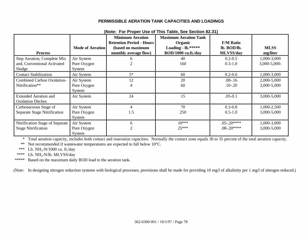
362-0300-001 / 10/1/97 / Page 78
PERMISSIBLE AERATION TANK CAPACITIES AND LOADINGS
(Note: For Proper Use of This Table, See Section 82.31)
ProcessMode of Aeration
Minimum AerationRetention Period - Hours
(based on maximummonthly average flow)
Maximum Aeration TankOrganic
Loading - lb.*****BOD/1000 cu.ft./day
F/M Ratiolb. BOD/lb.MLVSS/day
MLSSmg/liter
Step Aeration, Complete Mixand, Conventional ActivatedSludge
Air SystemPure OxygenSystem
62
40160
0.2-0.50.3-1.0
1,000-3,0003,000-5,000-
Contact Stabilization Air System 5* 60 0.2-0.6 1,000-3,000Combined Carbon Oxidation-Nitrification**
Air SystemPure OxygenSystem
124
2060
.08-.16
.10-.202,000-5,0003,000-5,000
Extended Aeration andOxidation Ditches
Air System 24 15 .05-0.1 3,000-5,000
Carbonaceous Stage ofSeparate Stage Nitrification
Air SystemPure OxygenSystem
41.5
70250
0.3-0.80.5-1.0
1,000-2,5003,000-5,000
Nitrification Stage of SeparateStage Nitrification
Air SystemPure OxygenSystem
62
10***25***
.05-.20****
.08-.20****1,000-3,0003,000-5,000
* Total aeration capacity, includes both contact and reaeration capacities. Normally the contact zone equals 30 to 35 percent of the total aeration capacity.** Not recommended if wastewater temperatures are expected to fall below 10°C.
*** Lb. NH3-N/1000 cu. ft./day**** Lb. NH3-N/lb. MLVSS/day
***** Based on the maximum daily BOD load to the aeration tank.
(Note: In designing nitrogen reduction systems with biological processes, provisions shall be made for providing 10 mg/l of alkalinity per 1 mg/l of nitrogen reduced.)
362-0300-001 / 10/1/97 / Page 79
82.32 Arrangement of Aeration Tanks
82.321 General Tank Configuration
a. Dimensions - The dimensions of each independent mixed liquor aerationtank or return sludge reaeration tank shall be such as to maintain effectivemixing and utilization of air. Ordinarily, liquid depths should not be lessthan 10 feet or more than 30 feet except in special design cases such asoxidation ditch design.
b. Short Circuiting - For very small tanks or tanks with specialconfiguration, the shape of the tank, the location of the influent and sludgereturn, and the installation of aeration equipment should provide forpositive control of short circuiting through the tank.
82.322 Number of Units - Consideration should be given to dividing the requiredaeration tank volume into two or more units at all plants. For plants designed toreceive maximum monthly average flow of 50,000 gpd or more, total aerationtank volume shall be divided among two or more units capable of independentoperation, when required by the Department to meet applicable effluentlimitations and reliability guidelines.
82.323 Inlets and Outlets
a. Controls - Inlets and outlets for each aeration tank unit shall be suitablyequipped with valves, gates, stop plates, weirs, or other devices to permitcontrolling the flow to any unit and to maintain a reasonably constantliquid level. The hydraulic properties of the system shall permit the peakinstantaneous flow, including the maximum sludge return flow, to becarried with any single aeration tank unit out of service.
b. Conduits - Channels and pipes carrying liquids with solids in suspensionshall be designed to maintain self-cleansing velocities or shall be agitatedto keep such solids in suspension at all rates of flow within the designlimits. Adequate provisions should be made to drain segments of channelswhich are not being used due to alternate flow patterns.
82.324 Freeboard - All aeration tanks should have a freeboard of not less than18 inches. Where a mechanical surface aerator is used, the freeboard should benot less than three feet to protect against windblown spray freezing onwalkways.
82.325 Froth Spray - Use of a froth spray system to cut down the foam in the aerationtank should be considered. The froth spray pump(s) should preferably belocated in the chlorine contact tank to prevent clogging of nozzles. The frothspray lines in the aeration tank should point perpendicular to the flow.
82.326 Oxidation Ditches
a.Depth - The maximum liquid depth in the ditch shall be 12 feet for verticalsidewalls and six feet for sloping sidewalls. Large ditches should have at
362-0300-001 / 10/1/97 / Page 80
least two bottom drains for ease of emptying and cleaning. For ditchesgreater than six feet deep, consideration should be given to placing baffleswithin 15 feet downstream of aerators to provide proper mixing of theentire depth of the channel.
b. Inlet/Outlet - The raw wastewater inlet and return sludge flow shall belocated immediately upstream from the first brush (rotor). The outlet oroverflow weir device shall be located between the last brush and the inletof each ditch.
c. Brushes - Rotors or brushes are used to provide surface aeration foroxygen transfer and to keep the contents of the ditch mixed and moving.A velocity of the liquid in the ditch must be maintained at 1.0 to 1.5 feetper second to prevent the settling of solids. There shall be a minimum oftwo brushes per ditch for oxygen control and for continued operationshould a brush have a mechanical breakdown. With one brush out ofservice, adequate aeration and velocity shall be maintained by theremaining brushes through the sizing of the brushes and controlling thesubmergence. Consideration should be given in the colder areas to coverboth the brush and motor drive units to prevent an ice buildup problem atthe two ends of the brush shaft.
d. Weirs - Each ditch shall have an easily adjustable effluent control weir tovary the brush depth submergence in order to vary the amount of oxygentransfer.
e. Clarifiers following ditches should have both mechanical sludge scrapersand scum skimmers with baffle to prevent solids/scum carryover due to noprimary clarifiers. They should also have a positive means of sludgereturn to the ditch or wasting, along with a means of sludge returnmeasurement.
f. The entire ditch shall be lined with an impervious material to preventerosion and scouring by the liquid velocity in the ditch. Provisions shallalso be made to prevent surface runoff from entering the ditch.
82.33 Aeration Equipment
82.331 General - Oxygen requirements generally depend on maximum diurnal organicloading, degree of treatment, and level of suspended solids concentration to bemaintained in the aeration tank mixed liquor. Aeration equipment shall becapable of maintaining a minimum of two mg/l of dissolved oxygen in the mixedliquor at all times and providing thorough mixing of the mixed liquor.
In the absence of experimentally determined values, the design oxygenrequirements for all activated sludge processes shall be 1.1 lbs oxygen/lb.maximum daily BOD applied to the aeration tanks at working conditions, withthe exception of the extended aeration process, for which the value shall be 1.5to include endogenous respiration requirements. In addition, the oxygendemands due to recycle flows (heat treatment supernatant, filtrate from
362-0300-001 / 10/1/97 / Page 81
dewatering operations, elutriates, etc.) must be considered due to the highconcentrations of BOD and ammonia associated with such flows.
In the case of nitrification, the oxygen requirement for oxidizing ammonia mustbe added to the above requirement for carbonaceous BOD removal andendogenous respiration requirements. The nitrogenous oxygen demand (NOD)shall be taken as 4.6 times the maximum daily ammonia content of the influentto the aeration tank.
Careful consideration should be given to maximizing oxygen utilization per unitpower input. Unless flow equalization is provided, the aeration system shouldbe designed to match the diurnal organic load variation while economizing onpower input.
82.332 Diffused Air Systems - The design of the diffused air system to provide oxygenrequirements shall be performed by either of the two methods described in (a) or(b) and augmented as required by considerations of items (c) through (g).
a. Having determined the oxygen requirements per Section 82.331, airrequirements for a diffused air system shall be determined by use of anyof the well-known equations incorporating such factors as tank depth,alpha factor of waste, beta factor of waste, certified aeration devicetransfer efficiency, minimum aeration tank dissolved oxygenconcentrations, critical wastewater temperature, and altitude of plant.
In the absence of experimentally determined alpha and beta factors,wastewater transfer efficiency shall be assumed to be 50 percent of cleanwater efficiency for plants treating primarily (90 percent or greater)domestic wastewater. Treatment plants where the waste contains higherpercentages of industrial wastes shall use a correspondingly lowerpercentage of clean water efficiency and shall have calculations submittedto justify such a percentage. The design transfer efficiency should beincluded in the specifications.
b. Minimum air requirements for all activated sludge processes (excludingnitrogenous oxygen demand) except extended aeration (assumingequipment capable of transmitting to the mixed liquor the amount ofoxygen required in Section 82.331) shall be considered to be 1,500 cu. ft.per pound of maximum daily BOD aeration tank loading at standardconditions of pressure, temperature, and humidity. For the extendedaeration process, the value shall be 2,050 cu. ft. per pound of maximumdaily BOD aeration tank loading at standard conditions of pressure,temperature, and humidity. These requirements include mixing but do notinclude oxygen demand for nitrification. Refer to Section 82.331.
c. To the air requirements calculated above shall be added the air requiredfor channels, air lifts, aerobic digesters, or other air-use demand.
d. The specified capacity of blowers or air compressors, particularlycentrifugal blowers, should take into account that the air intake
362-0300-001 / 10/1/97 / Page 82
temperature may reach 104°F or higher, and the pressure may be less thannormal. The specified capacity of the motor drive should also take intoaccount that the intake air may be 22°F or less and may require oversizingof the motor or a means of reducing the rate of air delivery to preventoverheating or damage to the motor.
e. All blowers and electrical controls shall be located in a building or aheated, walk-in enclosure.
The blowers shall be provided in multiple units, so arranged and in suchcapacities as to meet the maximum air demand with the single largest unitout of service. The design shall also provide for varying the volume of airdelivered in proportion to the load demand of the plant. The use of timersto conserve energy is acceptable, provided necessary minimum dissolvedoxygen level is maintained in the aeration tank. Aeration equipment shallbe easily adjustable in increments and shall maintain solids in suspensionwithin these limits. Step type proportioning is acceptable.
f. Diffuser systems shall be capable of providing for the diurnal peakoxygen demand or 200 percent of the design average oxygen demand,whichever is larger. The air diffusion piping and diffuser system shall becapable of delivering normal air requirements with minimal friction losses.
Air piping systems should be designed such that total air loss from bloweroutlet (or silencer outlet where used) to the diffuser inlet does not exceed0.5 psi at normal operating conditions.
The spacing of diffusers should be in accordance with the oxygenrequirements through the length of the channel or tank, and should bedesigned to facilitate adjustment of their spacing without major revision toair header piping. Diffusers should be located one to two feet from thebottom of the tank when operating.
All plants employing less than four independent aeration tanks shall bedesigned to incorporate removable diffusers that can be serviced and/orreplaced without dewatering the tank. However, use of fixed diffusersmay be approved on a case-by-case basis if it is demonstrated that thebuilt-in design and/or operational flexibility can keep the facility incompliance when one of the tanks is out-of-service or not in operation dueto maintenance.
g. Individual assembly units of diffusers shall be equipped with controlvalves, preferably with indicator markings for throttling, or for completeshutoff. Diffusers in any single assembly shall have substantially uniformpressure loss.
Air filters shall be provided in numbers, arrangements, and capacities tofurnish at all times an air supply sufficiently free from dust to preventdamage to blowers and clogging of the diffuser system used.
362-0300-001 / 10/1/97 / Page 83
82.333 Mechanical Aeration Systems
a. Oxygen Transfer Performance - The mechanism and drive unit shall bedesigned for the expected conditions in the aeration tank in terms of thepower performance. Certified on-line testing shall verify mechanicalaerator performance based on similar geometrical tank design. Refer toapplicable Section 82.332a. In the absence of specific design information,the oxygen requirements shall be calculated using a transfer rate not toexceed two lbs. of oxygen per horsepower per hour in clean water atstandard conditions. Design transfer efficiency shall be included in thespecifications.
b. Design Requirements - The design requirements of a mechanical aerationsystem shall accomplish the following:
1. Maintain a minimum of two mg/l of dissolved oxygen in themixed liquor at all times throughout the tank or basin.
2. Maintain all biological solids in suspension.
3. Meet maximum oxygen demand and maintain processperformance with the largest unit out of service.
4. Provide for varying the amount of oxygen transferred inproportion to the load demand on the plant.
5. Provide that motors, gear housing, bearings, grease fittings, etc.,be easily accessible and protected from inundation and spray asnecessary for proper functioning of the unit.
c. Winter Protection - Where extended cold weather conditions occur, theaerator mechanism and associated structure shall be protected fromfreezing due to splashing. Due to high heat loss, subsequent treatmentunits shall be protected from freezing.
83. Rotating Biological Contactors
83.1 General
83.11 Applicability - The Rotating Biological Contactor (RBC) process may be used wherewastewater to be treated is amenable to aerobic biological treatment. This process maybe used to accomplish carbonaceous and/or nitrogenous oxygen demand reductions.
83.12 Winter Protection - Wastewater temperature affects RBC performance. Year-roundoperating requires that RBCs be covered to protect the biological growth from coldtemperatures and the excessive loss of heat from the wastewater with the resulting lossof performance.
362-0300-001 / 10/1/97 / Page 84
Enclosures shall be constructed of a suitable corrosion-resistant material. Windows orsimple louvered mechanisms which can be opened in the summer and closed in thewinter shall be installed to provide adequate ventilation. To minimize condensation, theenclosure should be adequately insulated and/or heated.
83.2 Pretreatment - Effective treatment, through the use of primary clarifiers equipped with scumand grease collecting devices, must be provided ahead of RBC units unless substantialjustification is submitted for other pretreatment devices which provide for effective removal ofgrit, debris and excessive oil or grease prior to the RBC units. Bar screening or comminution isnot suitable as the sole means of pretreatment.
83.3 Design Considerations
83.31 Process Loading and Reliability - To assure continued and reliable performance, thefollowing items shall be considered in designing RBC process.
a. Design loadings applied to the first RBC stage should not exceed five to six lbs.total BOD/day/1,000 sq. ft. or two and one-half lbs. soluble BOD/day/1,000.Soluble BOD loading should be verified by influent sampling whenever possible.Organic loading considerations during design must include contributions fromin-plant sidestreams, septage dumps, etc.
b. When peak to average flow ratio is 2.5 to 1 or less, average conditions can be usedfor design. For higher flow ratios, flow equalization should be considered.
c. If periodic high loadings are expected, supplemental aeration in the first stageshould be considered.
d. Manufacturer’s literature indicates that organic removal and nitrification ratesdiminish at wastewater temperatures below 55° F. Appropriate temperaturecorrection factor should be used to determine needed additional media surface fortemperatures below 55° F.
e. High influent hydrogen sulfide (H2S) concentrations can impede RBCperformance because of the acceleration of the nuisance growth. When higherthan normal influent or side stream H2S concentrations are anticipated,appropriate modifications in the design should be considered.
f. High density media should not be used in first and second stages.
g. A means of removing excess biofilm growth, such as by air or water stripping,chemical additions, rotational speed control/reversal, etc.; should be provided.
h. Need for additional media surface should be evaluated when ammonia nitrogenlevels are required in the effluent. Manufacturer’s literature should be consultedin determining this.
i. First-stage dissolved oxygen (DO) monitoring should be provided. The RBC unitshould be designed to maintain a positive DO level in all stages.
j. To the extent possible, RBCs should not be installed in buildings. However, whenRBCs are installed in buildings, adequate ventilation, humidity control, need forremoval of shaft and media, and heating requirements must be considered.
362-0300-001 / 10/1/97 / Page 85
k. Design should clearly show the effect of varying loadings to the various stages ofthe process to assure compliance with effluent limits and prevent structuraldamage to shafts and media caused by organic loadings exceeding processcapability.
l. RBC system should be such that effluent limits are met with some units out ofservice. This may be necessary for recoating shafts for corrosion control, mediareplacement or repair, bearing replacement, etc. that would mandate such needs.
If such process reliability needs are not or cannot be met through flexibility in thedesign flow, then added standby units should be provided to insure processcontinuity and prevent mechanical/structural failure with short-term overload.
m. Careful consideration should be given to providing power factor correction for allRBC mechanical and air driven systems.
n. The use of high-efficiency motors for mechanically driven RBC units to lower theenergy consumption should be considered.
83.32 Mechanical Reliability and Structural Integrity - Some of the early generation RBCs hadsuffered failures to shafts, drives, bearings, and media. The following shall beconsidered for achieving reliable RBC performance.
a. The load-bearing capacity for each shaft that considers the maximum anticipatedbiofilm growth, the capacity to strip excess biofilm, and an adequate margin ofsafety should be specified in the contract documents.
b. The manufacturer should be required to provide adequate assurance that the shaftand media support structures are protected from structural failures for the designlife of the facility. Structural designs should be based on appropriate AmericanWelding Society (AWS) stress category curves modified as necessary to accountfor expected corrosive environment. All fabrication during construction shouldconform to AWS welding and quality control standards.
c. Load cells should be provided for all first and second stage shafts. Load cells forall of the shafts in an installation are desirable.
d. The design should consider impact of stress reversals on the plastic media over thedesign life. The specifications should require the manufacturer to provideadequate assurance that the premature media failures, including collapse,wobbling on shaft, accordian action, shifting within cage, etc., will not occur.
e. Bearings and drive systems must be designed for a ten year life using appropriateanti-friction bearing Manufacturer's Association criteria and the American GearManufacturer’s Association criteria. RBC shaft bearings must be of theself-aligning type designed to effectively retard the entrance of foreign materialinto the lubricant.
f. The design life of such components as gear boxes, chains, motors, v-belts, fiberglass cover, etc. should be carefully reviewed and compared to available fieldexperience.
362-0300-001 / 10/1/97 / Page 86
g. The specifications should require that provisions be made to protect the plasticmedia from direct exposure to sunlight (ultraviolet degradation) during deliveryand construction.
83.33 Operation and Maintenance - Adequate flexibility in process operation and ease ofmaintenance should be provided by considering inclusion of the following items.
a. Variable rotational speeds in first and second stages.
b. Multiple treatment trains.
c. Removable baffles between all stages.
d. A suitably sized drain line with a shut-off valve for each unit or flow train to allowdewatering of the basin.
e. Positive influent flow control to each unit or flow train; for example, a flowsplitter box to control the flow to each unit or flow train.
f. Positively controlled alternate flow distribution systems, such as step feed.
g. Positive air flow metering and control to each shaft when supplemental aeration orair drive units are used.
h. Recirculation of secondary clarifier effluent.
i. Ease of access to shaft, media and other mechanical equipment needinginspection/maintenance and possible periodic removals/replacement.
j. Use of self-aligning, moisture resistant bearings.
84. Intermittent Sand Filters
Secondary treatment by sand filters is generally considered feasible only for institutional or relativelysmall community treatment plants. The use of subsurface or covered sand filters is not recommendedexcept for private installations where flows do not exceed 10,000 gallons per day.
84.1 Loading on Sand Filters
84.11 Primary Effluent - With acceptable primary treatment of normal wastewater, loadingshall not exceed 2.3 gallons per square foot of filter area per day.
84.12 Trickling Filter and Activated Sludge Effluent - Loading shall not exceed 10 gallons persquare foot of filter area per day.
84.13 Septic Tank Effluent on Surface Filters - For the effluent of septic tanks treating normaldomestic wastewater from small community installations, institutions, motels, etc., theloading shall not exceed 2.3 gallons per square foot of filter area per day. Forsummertime operations extending not longer than 90 days per year, this loading may beincreased to 2.9 gallons per square foot per day, provided the septic tank is cleaned atleast once each year. However, in no case may the BOD load reaching the filter exceed140 pounds per acre per day.
362-0300-001 / 10/1/97 / Page 87
84.14 Septic Tank Effluent on Subsurface Filters - For the effluent of septic tanks treatingnormal domestic wastewater from private installations, the flow shall not exceed 10,000gallons per day, and the loading shall not exceed 1.5 gallons per square foot of filter areaper day.
84.2 Media
84.21 Gravel Base - Clean, graded gravel, preferably placed in at least three layers, should beplaced around the underdrains and to a depth of at least six inches over the top of theunderdrains. Suggested gradings for the 3 layers are 1 1/2 inches to 3/4 inch, 3/4 inch to1/4 inch, and 1/4 inch to 1/8 inch.
84.22 Sand - At least 24 inches of clean sand should be provided. For open filters dosed byflooding, the effective size shall be 0.3 to 0.6 mm; for filters dosed by rotarydistributors, the effective size shall be 0.5 to 1.0 mm. The uniformity coefficient shallnot be greater than 3.5.
84.3 Dosing
84.31 General - Facilities for dosing of the filter media shall be provided to assure an adequaterest period between two subsequent applications.
84.32 Duplicate Units - Two or more filters are necessary to provide for maintenance andadequate rest periods between doses.
84.33 Volume - The dosing tank volume shall be such that any open filter bed will be coveredto a depth of two to four inches by each dose. Subsurface filter dosing should be donesuch that pipes are filled to 60-75 percent depth per dose.
84.34 Siphons or Pumps - Siphons or pumps shall have a discharge capacity at minimum headat least 100 percent in excess of the maximum rate of inflow to the dosing tank, and ataverage head, at least 90 gallons per minute per 1,000 square feet.
84.35 Discharge Lines - The discharge lines to the beds shall have sufficient capacity to permitthe full rated discharge of the siphons or pumps.
84.4 Distribution
84.41 Arrangement - Troughs or piping may be used for distribution of the settled wastewaterover the filter surface and should be so located that the maximum lateral travel is notmore than 20 feet. Provisions should be made for adjustment of the flow.
84.42 Splash Slabs - Splash slabs are needed at each point of discharge.
84.43 Drain - A drain opening from troughs or discharge piping is essential.
84.5 Underdrains - Open joint or perforated pipe underdrains of durable material may be used. Theyshould be sloped to the outlet and spaced not to exceed 10-foot centers.
84.6 Earthen Base - The earthen base of the filters should be sloped to the trenches in which theunderdrains are laid. An impervious liner shall be installed on the pervious earth based toprevent seepage to the groundwater table.
84.7 Curbs - Provision should be made to prevent soil from washing onto the beds.
362-0300-001 / 10/1/97 / Page 88
84.8 To assure effective winter operation, filter covers shall be a design consideration.
85. Wastewater Treatment Ponds
85.1. General - The use of wastewater treatment ponds should be considered in those instances wherethe required level of wastewater treatment is compatible with pond technology and whereadverse environmental impacts can be avoided. It must be recognized that wastewater treatmentponds are not an answer to all wastewater treatment problems in Pennsylvania. Availability ofland at a reasonable cost often determines their viability. Each proposal to use ponds will beevaluated in light of the effects of the proposed discharge on water quality (both surface andgroundwater), including ability to meet the effluent requirements on a consistent basis and anyother considerations necessary to protect the public health. Applicants are encouraged toinvestigate the use of pond systems as a possible alternative to other biological, physical and/orchemical treatment processes. The wastewater treatment pond alternative should be evaluatedearly in the project development stage for cost-effective and environmental considerations.
85.2. Engineer’s Report - The engineer’s report shall contain pertinent information on location,geology, soil conditions, area for expansion and any other factors that will affect the feasibilityand acceptability of the proposed project. The following information must be submitted inaddition to that required in Chapter 10.
85.21 Supplementary Field Survey Data
85.211 The location and direction of all residences, commercial developments, parks,recreational areas and water supplies, within one-half mile of the proposed pondshall be included in the engineer’s report.
85.212 Land use zoning adjacent to the proposed pond site shall be included.
85.213 A description, including maps showing elevations and contours of the site andadjacent area, shall be provided. Due consideration shall be given to additionaltreatment units to meet any applicable discharge standards and/or increasedwaste loadings in determining land requirements. Current U.S. GeologicalSurvey and Soil Conservation Service maps may be considered adequate forpreliminary evaluation of the proposed site.
85.214 The location, depth and discharge point(s) of any field tile in the immediate areaof the proposed site shall be identified.
85.215 Data from soil borings conducted by a soil testing laboratory to determinesubsurface soil characteristics and groundwater characteristics, includingelevation and flow of the proposed site and their effect on the construction andoperation of a pond, shall be provided. At least one boring shall be a minimumof 25 feet in depth or into bedrock, whichever is shallower. If bedrock isencountered, structure and corresponding geological formation data should beprovided. The boring shall be filled and sealed. The permeabilitycharacteristics of the pond bottom and pond seal materials shall also be studied.(Refer to Section 85.53)
85.22 Location
362-0300-001 / 10/1/97 / Page 89
85.221 Distance from Habitation - A pond site should be located as far away aspracticable from habitation or any area which may be built up within areasonable future period, taking into consideration site specifics such astopography, prevailing winds, forests, etc.
85.222 Prevailing Winds - If practicable, unaerated ponds shall be located so that localprevailing winds will be in the direction of uninhabited areas.
85.223 Surface Runoff - Adequate provisions must be made to divert storm wateraround the ponds to prevent excess hydraulic loading and protect pondembankments from erosion.
85.224 Hydrology - Construction of ponds in close proximity to public and/or privategroundwater supplies subject to contamination shall be avoided. A minimumseparation of four feet between the top of the pond seal and the maximum highwater table should be maintained.
85.225 Geology - Ponds shall not be located in areas which may be subject to sink holesor solution channeling generally occurring in areas underlaid by limestone ordolomite.
A minimum separation of 10 feet between the pond bottom and any bedrockformations is recommended.
85.3 Pond Types and Classification
85.31 Pond Types - The wastewater treatment ponds are basically grouped into the followingtwo types based on discharge method.
a. Flow through ponds in which the pond discharges relatively continuouslythroughout the year; and
b. Controlled discharge ponds in which the pond is designed to retain the wastewaterwithout discharge for a long period and discharge it over a short period.
85.32 Pond Classification - The wastewater treatment ponds are broadly classified as aerobic,anaerobic and facultative.
Aerobic ponds are characterized by having dissolved oxygen distributed throughout theircontents practically all of the time. The required oxygen may be supplied by algaeduring daylight, and by mechanical or diffused aeration.
Anaerobic ponds usually are without any dissolved oxygen throughout their entire depth.The treatment depends on fermentation of sludges at the bottom. This process can bequite odorous and is generally not utilized for treating domestic wastewater.
Facultative ponds are the most common type used in treating domestic wastewater. Theupper layer of these ponds is aerobic, while the bottom layer is anaerobic. Algae supplymost of the required oxygen to the upper layer. Aeration of upper layer to dissolve andmix oxygen in the wastewater may also be required.
85.4 Basis of Design
362-0300-001 / 10/1/97 / Page 90
85.41 Loading for Controlled Discharge Facultative Treatment Pond Systems - Pond designfor BOD loading should range from 15 to 35 pounds per acre per day (at the meanoperating depth) in the primary cells and a minimum of 90 days detention time betweenthe two foot and the maximum operating depth of the entire pond system. The meanoperating depth can be calculated as the maximum operating depth plus minimumoperating depth divided by two. The detention time and organic loading rate shalldepend on climatic condition and effluent requirements.
85.42 Loading for Flow-Through Facultative Treatment Pond Systems - Pond design for BODloading should vary from 15 to 35 pounds per acre per day for the primary cells. Themajor design considerations for BOD loading must be directly related to the climaticconditions.
Design variables such as pond depth, multi-units, detention time and additional treatmentunits must be considered with respect to applicable standards for BOD, total suspendedsolids (TSS), fecal coliforms, nutrients, dissolved oxygen (DO), and pH.
A detention time of 90-120 days for the entire pond system should be provided; however,this must be properly related to other design considerations. It should be noted that themajor factor in the design is the duration of the cold weather period (water temperatureless than 5°C).
85.43 Aerated Treatment Pond Systems - These ponds are of the flow-through type. Theminimum detention time for aerated pond system design may be estimated using thefollowing formula; however, for the development of final design parameters, it isrecommended that actual experimental data be developed.
tE
K x E=
−2 3 1 100. ( ) ( )
t = detention time, days
E = percent of BOD to be removed in aerated pond
K(1) reaction coefficient, aerated lagoon, base 10. For complete treatmentof normal domestic sewage, the K(1) value may be assumed to be0.20/day at 20°C. or 0.06/day at 0°C.
The reaction rate coefficient for wastewater to be treated, which may include domesticand non domestic wastewater, must be determined experimentally for various conditionswhich might be encountered in the aerated ponds. Conversion of the reaction ratecoefficient at temperatures other than 20°C. shall be based on empirical data.
Raw wastewater strength should consider the impact of any recirculated wastewater.Also, additional storage time should be considered for sludge storage and, in northernclimates, ice cover.
Oxygen requirements generally will depend on the BOD loadings, the degree oftreatment, and the concentration of suspended solids to be maintained. Aerationequipment shall be capable of maintaining a minimum dissolved oxygen level oftwo mg/l in the ponds at all times. Sizing of the aeration equipment shall be based on thelarger of the following: (1) mixing requirements; (2) oxygen requirements using
362-0300-001 / 10/1/97 / Page 91
summertime kinetics, including allowance for nitrification. Aerated ponds should bedesigned to achieve complete mixing. Suitable protection shall be provided for electricalcontrols.
85.44 Industrial Wastes - Consideration shall be given to the type and effects of industrialwastes on the treatment process. In some cases it may be necessary to pretreat industrialor other discharges.
Industrial wastes shall not be discharged to ponds without assessment of the effects suchwastes may have upon the treatment process or discharge requirements in accordancewith state and federal laws.
85.45 Number of Cells - At a minimum, a pond system should consist of three cells designed tofacilitate both series and parallel operations. The maximum size of a pond should be40 acres. Two-cell systems may be utilized in very small installations having a flow of50,000 gpd or less.
All systems should be designed with piping flexibilities to permit isolation of any cellwithout affecting the transfer and discharge capabilities of the total system. In addition,the ability to discharge the influent waste load to a minimum of two cells and/or allprimary cells in the system should be provided.
85.451 Controlled Discharge Facultative Treatment Pond Systems - For controlleddischarge systems, the area specified as the primary pond(s) should be equallydivided into two cells, and the third cell or secondary pond volume should be aminimum of one-third the total volume of the entire system.
In addition, design should permit for adequate elevation difference betweenprimary and secondary ponds to permit gravity filling of the secondary pondfrom the primary pond. When this is not feasible, pumping facilities shall beprovided.
85.452 Flow-Through Facultative Treatment Pond Systems - At a minimum, primarypond(s) shall provide adequate detention time to maximize BOD removal.Secondary pond(s) should then be provided for additional detention time withdepths up to eight feet to facilitate solids reduction. Design should also considerrecirculation within the system.
85.453 Aerated Treatment Pond Systems - For a total aerated pond system, a minimumof three cells employing a tapered mode of aeration is recommended. Whenutilizing wastewater by method of spray irrigation, aerated ponds arerecommended, followed by an unaerated storage pond.
85.46 Pond Shape - The shape of all cells shall be such that there are no narrow or elongatedportions. Round, square, or rectangular ponds with a length not exceeding three timesthe width are considered most desirable. No islands, peninsulas, or coves shall bepermitted. Dikes shall be rounded at corners to minimize accumulations of floatingmaterials. Common dike construction whenever possible is strongly encouraged.
85.47 Additional Treatment - Consideration should be given in the design stage to theutilization of additional treatment units as may be necessary to meet applicable dischargestandards.
85.5 Pond Construction Details
362-0300-001 / 10/1/97 / Page 92
85.51 Embankments and Dikes
85.511 Material - Dikes shall be constructed of relatively impervious material andcompacted to at least 90 percent Standard Proctor Density to form a stablestructure. Vegetation and other unsuitable materials shall be removed from thearea where the embankment is to be placed.
85.512 Top Width - The minimum dike top width shall be 10 feet to permit access ofmaintenance vehicles.
85.513 Maximum Slopes - Inner and outer dike slopes shall not be steeper thanthree horizontal to one vertical (3:1).
85.514 Minimum Slopes - Inner slopes should not be flatter than four horizontal toone vertical (4:1). Flatter slopes can be specified for larger installations becauseof wave action but have the disadvantage of added shallow areas beingconducive to emergent vegetation. Outer slopes shall be sufficient to preventsurface runoff from entering the ponds.
85.515 Freeboard - Minimum freeboard shall be three feet. For systems havingmaximum monthly average flow of 50,000 gpd or less, 2 feet may beacceptable.
85.516 Design Depth - The minimum operating depth should be sufficient to preventgrowth of aquatic plants and damage to the dikes, bottom, control structures,aeration equipment, and other appurtenances due to freezing and erosion. In nocase shall the minimum operating depth be less than two feet.
a. Controlled Discharge and Flow-Through Facultative Treatment Ponds -The maximum water depth shall be six feet in primary cells. Greaterdepths in subsequent cells are permissible although supplemental aerationor mixing may be necessary.
b. Aerated Treatment Pond Systems - The design water depth shall be10-15 feet. This depth limitation may be altered depending on the aerationequipment, waste strength and climatic conditions.
85.517 Erosion Control - A justification including detailed discussion of the method oferosion control which encompasses all relative factors such as pond location andsize, seal material, topography, prevailing winds, run off, etc., shall be provided.
a. Seeding - The dikes shall have a cover layer of at least four inches offertile topsoil to promote establishment of an adequate vegetative coverwherever riprap is not utilized. Prior to prefilling (in accordance withSection 85.534), adequate vegetation shall be established on dikes fromthe outside toe to the expected low operating water level elevation.Perennial-type, low-growing, spreading grasses that minimize erosion andcan be mowed are most satisfactory for seeding of dikes. In general,alfalfa and other long-rooted crops should not be used for seeding sincethe roots of this type are apt to impair the water holding efficiency of thedikes.
362-0300-001 / 10/1/97 / Page 93
b. Additional Erosion Protection - Riprap or some other acceptable methodof erosion control is required at a minimum around all piping entrancesand exits. For aerated cells, the design should ensure erosion protectionon the slopes and bottoms in the areas where turbulence will occur.Additional erosion control may also be necessary on the exterior dikeslope to protect the embankment from erosion due to severe flooding of awater course.
c. Alternate Erosion Protection - Alternate erosion control on the interiordike slopes may be necessary for ponds which are subject to severe waveaction. In these cases, riprap or acceptable equal shall be placed fromone foot above the high water mark to two feet below the low water mark(measured on the vertical).
85.52 Pond Bottom - Soil used in constructing the pond bottom (not including seal) and dikecores shall be relatively incompressible and tight. Soil should have an optimum moisturecontent and be compacted at or up to four percent above the specified Standard ProctorDensity, but no less than 90 percent Standard Proctor Density. The pond bottom shallbe as level as possible at all points and shall be at least four feet above the highgroundwater table.
85.53 Pond Sealing
85.531 General Requirements - Ponds shall be sealed in such a manner that seepagelosses through the pond sides and bottom are minimized. Sealing methods usingon-site soils, bentonite, or other types of synthetic liners may be approved if itcan be demonstrated that the proposed sealing method will be sufficientlyimpermeable and will remain structurally sound during all anticipated workingconditions.
The use of on-site soils should be demonstrated and documented through soilborings and testing during the design phase.
To insure an adequate seal, it must be demonstrated that the coefficient ofpermeability, K, of the pond sides and the bottom will not exceed 1 X 10⁻⁷centimeters per second.
A construction procedure and testing program which will insure the adequacy ofthe sealing method must be incorporated into the specifications. StandardASTM procedures, or their equivalent, shall be utilized where applicable.
Upon completion of construction, a written completion certification that the sealhas been adequately constructed and tested in accordance with projectspecifications shall be submitted by the engineer to the Department.
85.532 Liner Materials - Bentonite and other forms of synthetic liners shall be designedand constructed in accordance with manufacturers’ recommendations. Theproject engineer shall confirm the physical-chemical compatibility of the liningmaterial with the wastewater being treated (with particular emphasis on anyindustrial wastes which may be present).
Flexible membrane liners shall have a minimum thickness of .030 inches or30 mills.
362-0300-001 / 10/1/97 / Page 94
85.533 Groundwater Monitoring and Leak Detection - A means of monitoring ambientgroundwater quality before and during pond operation shall be provided. Aminimum of one groundwater observation point shall be located in closeproximity to the pond system to intercept the groundwater table at a locationdowngradient from the pond system (in each major groundwater flow direction).
The following types of groundwater observation points may be acceptabledepending upon local conditions.
a. New or existing wellsb. Springsc. Well points or lysimetersd. Rock-lined test pits or trenches
Leak-detection mechanisms such as underdrain systems or soil-resistivitysensing devices will be acceptable as alternatives to the above-mentionedgroundwater observation points.
85.534 Prefilling - Prefilling the pond should be considered in order to protect the liner,to prevent weed growth, to reduce odor and to maintain the moisture content ofthe seal. However, the dikes must be completely prepared as described inSections 85.517a and/or 85.517b before the introduction of water.
85.54 Influent Lines
85.541 Material - Generally accepted material for underground sewer constructionshould be given consideration for the influent line to the pond. Unlinedcorrugated metal pipe should be avoided, however, due to corrosion problems.Other materials selected shall be suited to local conditions. In material selection,consideration must be given to the quality of the wastes, exceptionally heavyexternal loadings, abrasion, soft foundations and similar problems.
85.542 Manhole - A manhole or vented cleanout wye shall be installed prior to entranceof the influent line into the primary cell(s) and shall be located as close to thedike as topography permits. Its invert shall be at least six inches above themaximum operating level of the pond and provide sufficient hydraulic headwithout surcharging the manhole.
85.543 Flow Distribution - Flow distribution structures shall be designed to effectivelysplit hydraulic and organic loads equally to primary cells.
85.544 Placement - Influent line(s) for unaerated aerobic or facultative ponds should belocated along the bottom of the pond so that the top of the pipe is just below theaverage elevation of the pond seal; however, the pipe should have adequate sealbelow it.
Influent line(s) for aerated ponds may go directly through the dike and end at thetoe of the inner slope.
85.545 Point of Discharge - All primary cells of unaerated ponds shall have individualinfluent line(s) which terminate at the midpoint of the width and atapproximately two-thirds the length away from the outlet structure so as tominimize short-circuiting. Consideration should be given to multi-influent
362-0300-001 / 10/1/97 / Page 95
discharge points for large primary cells (20 acres or larger) to enhancedistribution of load on the cell.
All aerated cells shall have influent lines which distribute the load within themixing zone of the aeration equipment. Consideration of multi-inlets should beclosely evaluated for any diffused aeration systems.
85.546 Influent Discharge Apron - The influent line(s) shall discharge horizontally intoa shallow saucer-shaped depression.
The end of the discharge line(s) shall rest on a suitable concrete apron largeenough such that the terminal influent velocity at the end of the apron does notcause soil erosion. A minimum size apron of two feet square shall be provided.
85.55 Control Structures and Interconnecting Piping
85.551 Structure - Where possible, facilities design shall consider the use of multi-purpose control structures to facilitate normal operational functions such asdrawdown and flow distribution, flow and depth measurement, sampling, pumpsfor recirculation, chemical addition and mixing, and minimization ofconstruction sites within the dikes.
As a minimum, control structures shall be: (a) accessible for maintenance andadjustment of controls; (b) adequately ventilated for safety and to minimizecorrosion; (c) locked to discourage vandalism; (d) equipped with controls toallow variable water level and flow rate control, complete shut off and completedraining; (e) constructed of non-corrosive materials (metal on metal contact incontrols should be of like alloys to discourage electrochemical reaction); and (f)located to minimize short circuiting within the cell and avoid freezing and icedamage.
Recommended devices to regulate water level are valves, slide tubes, or dualslide gates. Regulators should be designed so that they can be preset to stopflows at any pond elevation.
85.552 Piping - All piping shall be of suitable materials. The piping shall not be locatedwithin or below the seal. Pipes should be anchored with adequate erosioncontrol.
(a) Drawdown Structure Piping
1. Submerged Discharges - For ponds designed for shallow or variabledepth operations, submerged discharges are recommended.Discharge pipes shall be located a minimum of 10 feet from the toeof the dike and two feet from the top of the seal and shall employ avertical withdrawal.
2. Multi-Level Discharges - For ponds that are designed deepenough to permit stratification of pond content, multipledischarges are recommended. There shall be a minimum ofthree withdrawal pipes at different elevations. The bottompipe shall conform with submerged discharge. Other pipes
362-0300-001 / 10/1/97 / Page 96
should utilize horizontal entrance. Adequate structuralsupport shall be provided.
3. Surface Discharge - For use under constant dischargeconditions and/or relatively shallow ponds under warmweather conditions, surface overflow-type withdrawal isrecommended. Design should evaluate floating weir box orslide tube entrance, with baffles for scum control.
4. Pond Drain - All ponds shall have emergency drawdownpiping to allow complete draining by either gravity or pumpingfor maintenance. These should be incorporated into the above-described structures.
5. Emergency Overflow - To prevent overtopping of dikes,emergency overflow should be provided with capacity to carrythe peak instantaneous flow.
(b) Hydraulic Capacity - The hydraulic capacity of structures and piping forthe flow-through system shall allow for a minimum of 250 percent of themaximum monthly average flow of the system.
The hydraulic capacity for controlled discharge systems shall permittransfer of water at a minimum rate of six inches of pond water depth perday at the available head. The discharge shall be as constant throughoutthe day as possible.
85.6 Miscellaneous
85.61 Fencing - The pond area shall be enclosed with an adequate fence to prevent livestockwatering and discourage trespassing. Fencing should not obstruct vehicle traffic on topof the dike. A vehicle access gate of sufficient width to accommodate mowingequipment shall be provided. All access gates shall be provided with locks.
85.62 Access - An all-weather access road shall be provided to the pond site to allow year-round maintenance of the facility.
85.63 Warning Signs - Appropriate permanent signs shall be provided along the fence aroundthe pond to designate the nature of the facility and advise against trespassing. At leastone sign shall be provided on each side of the site and one for every 500 feet of itsperimeter.
85.64 Flow Measurement - Flow measurement requirements are presented in Section 46.7.Effective weather protection shall be provided for the flow recorders.
85.65 Pond Level Gauges - Pond level gauges shall be provided.
85.66 Service Building - Consideration should be given to including a control building forlaboratory and maintenance equipment.
362-0300-001 / 10/1/97 / Page 97
85.67 Groundwater Monitoring - An approved system of wells or lysimeters may be requiredaround the perimeter of the pond site to facilitate groundwater monitoring. The need forsuch monitoring will be determined on a case-by-case basis.
86. Other Biological Treatment Processes
The use of secondary treatment processes other than those listed above will be considered by theDepartment on the merit of the process involved (see Section 9.4).
87. Land Treatment
87.1 General - The application of wastewater to the land by spraying and similar applicationmethods is considered to be ”ultimate” disposal with no further treatment necessary. The designof land application facilities must be such to achieve that goal. The recycling of wastewaterthrough the land has the additional benefits of recovery and utilization of nutrients andrecharging the groundwater system for existing and potential public and domestic use andmaintenance of surface water base flow. The Department encourages municipal officials andother applicants to investigate the use of land disposal of wastewater.
87.2 Pretreatment - A minimum of secondary treatment is generally required prior to land applicationof wastewater unless, in a specific case, the applicant can establish that a lesser degree ofpretreatment will not cause any health hazard or groundwater pollution problem.
Where wastewater contains refractory organics, heavy metals and other industrial wastes,additional pretreatment may be required to remove constituents that may not be renovated bythe soil and cause water pollution, or health hazards by adversely affecting soil where food maybe grown.
87.3 Design Considerations - The design of systems for the application of wastewater to the land isdependent upon and must relate to soil conditions, climate conditions, waste loadcharacteristics, and the groundwater flow system. Each site to be considered as a treatmentfacility for wastewater must be designed so as not to cause groundwater or surface waterpollution. The proposed design must reflect the existing site conditions and wastewatercharacteristics. The monitoring program must be such as to provide adequate data so thatgroundwater and surface water can be protected.
For detailed design criteria for projects utilizing land application, see Bureau of Water QualityProtection Publication “Manual for Land Application of Treated Sewage and IndustrialWastewater” (10/97).
88 through 89 - RESERVED FOR FUTURE USE
362-0300-001 / 10/1/97 / Page 98
90. ADVANCED WASTEWATER TREATMENT
91. High Rate Effluent Filtration
Granular media filters may be used as a tertiary treatment device for the removal of residualsuspended solids from secondary effluents. Filters may be necessary where effluent concentrations ofless than 15 mg/l of suspended solids and/or one mg/l of phosphorus must be achieved. Apretreatment process such as chemical coagulation and sedimentation or other acceptable processshould precede the filter units where effluent suspended solids requirements are less than 10 mg/l.
Care should be given in designing pipes or conduits ahead of filter units, if applicable, to minimizeshearing of floc particles. Consideration should be given in the plant design to provide flow-equalization facilities to moderate filter influent quality and quantity.
91.1 Filter Types - Filters may be of the gravity type or pressure type. Pressure filters shall beprovided with ready and convenient access to the media for treatment or cleaning. Wheregreases or similar solids which result in filter plugging are expected, filters should be of thegravity type.
91.2 Filtration Rates - Filtration rates shall not exceed five gpm/sq. ft. based on the design peakhourly flow rate applied to the filter units. The expected design maximum suspended solidsloading to the filter should also be considered in determining the necessary filter area.
Total filter area shall be provided in two or more units, and the filtration rate shall be calculatedon the total available filter area with one unit out of service.
91.3 Backwash
91.31 Backwash Rates - The backwash rate shall be adequate to fluidize and expand eachmedia layer a minimum of 20 percent based on the media selected. The backwashsystem shall be capable of providing a variable backwash rate. Minimum and maximumbackwash rates shall be based on demonstrated satisfactory field experience undersimilar conditions. The design shall provide for a minimum backwash period of10 minutes.
91.32 Backwash Pumps - Pumps for backwashing filter units shall be sized and interconnectedto provide the required backwash rate to any filter with the largest pump out of service.Filtered water from a clear well or chlorine tank shall be used as the source of backwashwater. Waste filter backwash shall be adequately treated.
91.33 Backwash Surge Control - The rate of return of waste filter backwash water to treatmentunits shall be controlled such that the rate does not exceed 15 percent of the maximummonthly average flow rate to the treatment units. The hydraulic and organic load fromwaste backwash water shall be considered in the overall design of the treatment plant.Surge tanks shall have a minimum capacity of two backwash volumes, althoughadditional capacity should be considered to allow for operational flexibility. Wherewaste backwash water is returned for treatment by pumping, adequate pumping capacityshall be provided with the largest unit out of service.
91.34 Backwash Water Storage - Total backwash water storage capacity in an effluentclearwell or chlorine contact tank shall equal or exceed the volume required for twocomplete backwash cycles.
362-0300-001 / 10/1/97 / Page 99
91.4 Filter Media Selection - Selection of proper media type and size will depend on required effluentquality, the type of treatment provided prior to filtration, the filtration rate selected, and filterconfiguration. In dual or multi-media filters, media size selection must consider compatibilityamong media. Media shall be selected and provided to meet specific conditions andrequirements relative to the project under consideration. The selection and sizing of the mediashall be based on demonstrated satisfactory field experience under similar conditions. All mediashall have a uniformity coefficient of 1.7 or less. The uniformity coefficient, effective size,depth and type of media shall be set forth in the specifications.
91.5 Filter Appurtenances - The filters shall be equipped with wash water troughs, surface wash orair scouring equipment, means of measurement and positive control of the backwash rate,equipment for measuring filter head loss, positive means of shutting off flow to a filter beingbackwashed, and filter influent and effluent sampling points. If automatic controls areprovided, there shall be a manual override for operating equipment, including each individualvalve essential to the filter operation. The underdrain system shall be designed for uniformdistribution of backwash water (and air, if provided) without danger of clogging from solids inthe backwash water. If air is to be used for filter backwash, separate backwash blower(s) shallbe provided.
Provision shall be made for periodic chlorination of the filter influent or backwash water tocontrol slime growths. When chemical disinfection is not provided, manual dosage of chlorinecompounds may be utilized.
91.6 Access and Housing - Each filter unit shall be designed and installed so that there is ready andconvenient access to all components and the media surface for inspection and maintenancewithout taking other units out of service. Housing for filter units shall be provided. Thehousing shall be constructed of suitable corrosion-resistant materials. All controls shall beenclosed, and the structure housing filter controls and equipment shall be provided withadequate heating and ventilation equipment to minimize problems with excess humidity.
91.7 Proprietary Equipment - Where proprietary filtration equipment not conforming to the precedingrequirements is proposed, data which support the capability of the equipment to meet effluentrequirements under design conditions shall be provided. Such equipment will be reviewed bythe Department on a case-by-case basis.
92. Phosphorus Removal by Chemical Treatment
Addition of lime or the salts of aluminum or iron may be used for chemical removal of solublephosphorus. The phosphorus reacts with the calcium, aluminum or iron ions to form insolublecompounds. Those insoluble compounds may be flocculated with or without the addition of acoagulant aid such as polyelectrolyte to facilitate separation by sedimentation.
92.1 Design Basis
92.11 Preliminary Testing - Laboratory, pilot, or full scale studies of various chemical feedsystems and treatment processes are recommended for existing plant facilities todetermine the achievable performance level, cost-effective design criteria, and ranges ofrequired chemical dosages.
The selection of a treatment process and chemical dosage for a new facility should be based onsuch factors as influent wastewater characteristics, effluent requirements, andanticipated treatment efficiency.
362-0300-001 / 10/1/97 / Page 100
92.12 System Flexibility - Systems shall be designed with sufficient flexibility to allow forseveral operational adjustments in chemical feed locations, chemical feed rates, andfeeding alternate chemical compounds.
92.2 Process Requirements
92.21 Dosage - The design chemical dosage shall include the amount needed to react with thephosphorus in the wastewater, the amount required to drive the chemical reaction to thedesired state of completion, and the amount required due to inefficiencies in mixing ordispersion. Excessive chemical dosage should be avoided.
92.22 Chemical Selection - The choice of lime or the salts of aluminum or iron should be basedon the wastewater characteristics and the economics of the total system.
When lime is used, it may be necessary to neutralize the high pH prior to subsequenttreatment in secondary biological systems prior to discharge in those flow schemeswhere lime treatment is the final step in the treatment process.
92.23 Chemical Feed Points - Selection of chemical feed points shall include consideration ofthe chemicals used in the process, necessary reaction times between chemical andpolyelectrolyte additions, and the wastewater treatment processes and componentsutilized. Flexibility in feed location shall be provided to optimize chemical usage.
92.24 Flash Mixing - Each chemical must be mixed rapidly and uniformly with the flowstream. Where separate mixing basins are provided, they should be equipped withmechanical mixing devices. The detention period should be at least 30 seconds.
92.25 Flocculation - The particle size of the precipitate formed by chemical treatment may bevery small. Consideration should be given in the process design for the addition ofsynthetic polyelectrolytes to aid settling. The flocculation equipment should beadjustable in order to obtain optimum floc growth, control deposition of solids, andprevent floc destruction.
92.26 Liquid-Solids Separation - The velocity through pipes or conduits from flocculationbasins to settling basins should not exceed 1.5 feet per second in order to minimize flocdestruction. Entrance works to settling basins should also be designed to minimize flocshear.
Settling basin design shall be in accordance with criteria outlined in Chapter 60. Fordesign of the sludge handling system, special consideration should be given to the typeand volume of sludge generated in the phosphorus removal process.
92.27 Filtration - Effluent filtration shall be considered where effluent phosphorusconcentrations of less than one mg/l must be achieved. Refer to requirements underSection 91.
92.3 Feed Systems - All liquid chemical mixing and feed installation should be installed on corrosion-resistant pedestals and elevated above the highest liquid level anticipated during emergencyconditions.
In general, the chemical feed equipment shall be designed to meet the maximum dosagerequirements for the design conditions. When lime is used as a coagulant, the feed equipmentshall be designed as a minimum to meet the chemical dosage requirements of 150 mg/l and
362-0300-001 / 10/1/97 / Page 101
300 mg/l of CaO for single stage lime treatment and two stage lime treatment, respectively.When alum or ferric chloride is used as a coagulant, the feed equipment shall be designed, as aminimum, to meet the dosage requirement of 16 mg/l of alum or 45 mg/l of ferric chloride foreach mg/l of phosphorus removal.
Lime feed equipment should be located so as to minimize the length of slurry conduits. Allslurry conduits shall be accessible for cleaning.
92.31 Liquid Chemical Feed Systems - Liquid chemical feed pumps should be of the positivedisplacement type with variable feed rate. Pumps shall be selected to feed the full rangeof chemical quantities required for the phosphorus mass loading conditions anticipatedwith the largest unit out of service.
Screens and valves shall be provided on the chemical feed pump suction lines.
An air break or anti-siphon device shall be provided where the chemical solution streamdischarges to the transport water stream to prevent an induction effect resulting inoverfeed.
Consideration shall be given to providing pacing equipment to optimize chemical feedrates.
92.32 Dry Chemical Feed System - Each dry chemical feeder shall be equipped with adissolver which is capable of providing a minimum five-minute retention at themaximum feed rate.
Polyelectrolyte feed installations should be equipped with two solution vessels andtransfer piping for solution makeup and daily operation.
Make-up tanks shall be provided with an educator funnel or other appropriatearrangement for wetting the polymer during the preparation of the stock feed solution.Adequate mixing should be provided by a large-diameter, low-speed mixer.
92.4 Storage Facilities
92.41 Size - Storage facilities shall be sufficient to insure that an adequate supply of thechemical is available at all times. Exact size required will depend on size of shipment,length of delivery time, and process requirements. Storage for a minimum of 10-day’ssupply should be provided.
92.42 Location and Containment - The liquid chemical storage tanks and tank fill connectionsshall be located within a containment structure having a capacity exceeding the totalvolume of all storage vessels. Valves on discharge lines shall be located adjacent to thestorage tank and within the containment structure.
Auxiliary facilities, including pumps and controls, within the containment area shall belocated above the highest anticipated liquid level. Containment areas shall be sloped to asump area and shall not contain floor drains.
Bag storage should be located near the solution make-up point to avoid unnecessarytransportation and housekeeping problems.
362-0300-001 / 10/1/97 / Page 102
92.43 Accessories - Platforms, stairs, and railings shall be provided as necessary to affordconvenient and safe access to all filling connections, storage tank entries, and measuringdevices.
Storage tanks shall have reasonable access provided to facilitate cleaning.
92.5 Other Requirements
92.51 Materials - All chemical feed equipment and storage facilities shall be constructed ofmaterials resistant to chemical attack by all chemicals normally used for phosphorusremoval in accordance with Section 47.
92.52 Temperature, Humidity, and Dust Control - Precautions shall be taken to preventchemical storage tanks and feed lines from reaching temperatures likely to result infreezing or chemical crystallization at the concentrations employed. A heated enclosureor insulation may be required. Consideration shall be given to temperature, humidity,and dust control in all chemical feed room areas.
92.53 Cleaning - Consideration shall be given to the accessibility of piping. Piping should beinstalled with plugging wyes, tees or crosses with removable plugs at changes indirection to facilitate cleaning.
92.54 Filling Drains and Draw-Off - Above-bottom drawoff from chemical storage or feedtanks shall be provided to avoid withdrawal of settled solids into the feed system. Abottom drain shall also be installed for periodic removal of accumulated settled solids.Provisions shall be made in the fill lines to prevent back siphonage of chemical tankcontents.
92.6 Safety and Hazardous Chemical Handling - The chemical handling facilities shall meet theappropriate safety and hazardous chemical handling facilities requirements of Section 47.
93 through 95. RESERVED FOR FUTURE USE
362-0300-001 / 10/1/97 / Page 103
100. DISINFECTION
101. General
The Department currently requires effective disinfection of wastewater to control disease-producingorganisms. The disinfection facilities design shall consider meeting both the bacterial standards anddisinfectant residual requirements in the effluent. The disinfection process should be selected afterdue consideration of waste characteristics, type of treatment provided prior to disinfection, waste flowrates, application and demand rates, pH of wastewater, cost of equipment, construction and operation,chemical availability, and maintenance problems.
If chlorination is utilized, it may be necessary to dechlorinate if the chlorine level in the effluent wouldimpair the natural aquatic habitat of the receiving stream.
102. Forms of Disinfection
Chlorine is the most commonly used chemical for wastewater disinfection. The forms most often usedare liquid chlorine and calcium or sodium hypochlorite. Chlorine tablets which erode in a controlledmanner may be used. Other disinfectants, including chlorine dioxide, ozone, bromine, ultravioletradiation, or hydrogen peroxide, may be accepted by the Department in individual cases.
103. Chlorine Disinfection
103.1 Type - Chlorine is available for disinfection in gas, liquid (hypochlorite solution) and pellet(hypochlorite tablet) form. The type of chlorine supply should be carefully evaluated duringthe facilities planning process. The use of chlorine gas or liquid will be most dependent on thesize of the facility and the chlorine dose required. Large quantities of chlorine such as arecontained in ton containers and tank cars represent a significant potential hazard to plantpersonnel and to the surrounding area should the container develop leaks. Both monetaryconsiderations and the potential public exposure to chlorine should be considered when makingthe final determination.
103.2 Chlorine Containers
103.21 Cylinders - 150 pound cylinders are typically used where chlorine consumption isless than 150 pounds per day. Cylinders should be stored in an upright positionwith adequate support brackets and chains at 2/3 of cylinder height for eachcylinder. The use of one-ton containers should be considered where the averagedaily chlorine consumption is over 150 pounds.
103.22 Tank Cars - At large installations, consideration should be given to the use of tankcars, generally accompanied by gas evaporators. Areawide public safety shall beevaluated as a part of the consideration. Provision of chlorine supply during tankcar switching shall be provided.
The tank car being used for the chlorine supply shall be located on a dead-end,level track that is a private siding. The tank car shall be protected from accidentalbumping by other railway cars by a locked derail device or a closed locked switchor both. The area shall be clearly posted “DANGER-CHLORINE”. The tank car
362-0300-001 / 10/1/97 / Page 104
shall be secured by adequate fencing with gates provided with locks for personneland rail access.
The tank car site shall be provided with a suitable operating platform at theunloading point for easy access to the protective housing or the tank car forconnection of flexible feedlines and valve operation. Adequate area lighting shallbe provided for night-time operation and maintenance.
103.23 Liquid Hypochlorite Solutions - Storage containers for hypochlorite solutions shallbe of sturdy, non-metallic lined construction and shall be provided with secure tanktops and pressure relief and overflow piping. Storage tanks should be eitherlocated or vented outside. Provision shall be made for adequate protection fromlight and extreme temperatures. Tanks shall be located where leakage will notcause corrosion or damage to other equipment. A means of secondary containmentshall be provided to contain spills and facilitate cleanup. Due to deterioration ofhypochlorite solutions over time, it is recommended that containers not be sized tohold more than one month’s needs. At larger facilities and locations where deliveryis not a problem, it may be desirable to limit on-site storage to one week.
103.24 Dry Hypochlorite Compounds - Dry hypochlorite compounds should be kept intightly closed containers and stored in a cool, dry location. Some means of dustcontrol should be considered, depending on the size of the facility and the quantityof compound used.
103.25 Scales - Scales for weighing cylinders shall be provided at all plants using chlorinegas. At large plants, scales of the indicating and recording type are recommended.As a minimum, a platform scale shall be provided. Scales shall be of corrosion-resistant material.
103.26 Evaporators - Where manifolding of several cylinders or ton containers will berequired to evaporate sufficient chlorine gas, consideration should be given to theinstallation of evaporators to produce the quantity of gas required. However,connection of cylinders or ton containers discharging liquid chlorine to a manifoldis not recommended.
103.27 Leak Detection and Controls - A bottle of 56 percent ammonium hydroxidesolution shall be available for detecting chlorine leaks. Where ton containers ortank cars are used, a leak repair kit approved by the Chlorine Institute shall beprovided. Consideration should be given to providing a caustic soda solutionreaction tank for absorbing the contents of leaking ton containers where suchcontainers are in use. Consideration should be given to the installation ofautomatic gas detection and related alarm equipment at large installations.
103.3 Feed Equipment
103.31 Type - Solution-feed, vacuum-type chlorinators are generally preferred for largechlorination installations. The use of hypochlorite feeders of the positivedisplacement type may be considered and are generally preferred when intermittentdisinfection is required. The preferred method of generation of chlorine dioxide is
362-0300-001 / 10/1/97 / Page 105
the injection of a sodium chlorite solution into the discharge line of the solution-feed gas-type chlorinator, with subsequent formation of the chlorine dioxide in areaction chamber at a pH of four or less. Erosion feed chlorinators capable ofproducing a design residual are acceptable, but use should be limited to plantswhere the flow does not exceed 10,000 gpd or as an emergency measure in largerplants with malfunctioning disinfection equipment.
The feed equipment should at least provide for disinfectant dosages which areproportionate to the effluent flow. Automatic dosage equipment should beprovided for larger plants.
103.32 Capacity - Disinfection capacity shall be adequate to produce an effluent that willmeet the fecal coliform limits specified by the Department for that installation.Required disinfection capacity will vary, depending on the uses and points ofapplication of the disinfection chemical. For domestic wastewater, the followingminimum dosing capacity may be used as a guide in sizing chlorination facilities.
Type of Treatment Chlorine Dosage
Trickling Filter and Rotating 12 mg/l Biological Contactor EffluentWaste Stabilization Pond Effluent 12 mg/lActivated Sludge Plant Effluent 8 mg/lTertiary Filtration Effluent 6 mg/lNitrified Effluent 6 mg/l
103.33 Standby Equipment and Spare Parts - Standby equipment of sufficient capacityshould be available to replace the largest unit during shutdowns. Spare parts shallbe available for all disinfection equipment to replace parts which are subject towear and breakage.
103.34 Chlorinator Water Supply - An ample supply of water shall be available foroperating the chlorinator. Where a booster pump is required, duplicate equipmentshould be provided. Standby power should be provided to insure adequatedisinfection in case of a power outage. Protection of a potable water supply shallconform to the requirements of Section 46.2. Adequately filtered plant effluentshould be considered for use in the chlorinator.
103.4 Piping and Connections - Piping systems should be as simple as possible, specifically selectedand manufactured to be suitable for chlorine service, and with a minimum number of joints.Piping should be well supported and protected against temperature extremes.
Due to the corrosiveness of wet chlorine, all lines designed to handle dry chlorine shall beprotected at the entrance from water or air containing water. Even minute traces of wateradded to chlorine results in a corrosive attack. Low pressure lines made of hard rubber, saran-lined, rubber-lined, polyethylene, polyvinylchloride (PVC), or other approved materials aresatisfactory for wet chlorine or aqueous solutions of chlorine. Sections of piping that conveyliquid chlorine and are isolated with valves at both ends must be provided with a suitableexpansion chamber.
362-0300-001 / 10/1/97 / Page 106
103.5 Housing
103.51 Feed and Storage Room - If gas chlorination equipment or chlorine cylinders are tobe in a building used for other purposes, a gas-tight room shall separate thisequipment. Such rooms shall be at ground level, and should permit easy access toall equipment. Floor drains from the chlorine room shall not be connected to floordrains from other rooms. Doors to this room shall open only to the outside of thebuilding, and shall be equipped with panic hardware. Storage area should beseparated from the feed area and the storage area should have designated areas for“full” and “empty” containers. Chlorination equipment should be situated as closeto the application point as reasonably possible.
103.52 Inspection Window - A clear glass, gas-tight window shall be installed in anexterior door or interior wall of the chlorinator room to permit the units to beviewed without entering the room.
103.53 Heat - Rooms containing chlorination equipment shall be provided with a means ofheating so that a temperature of at least 60°F can be maintained. The room shallbe protected from excess heat which could melt a fusible metal safety plug.Cylinders shall be kept at essentially room temperature.
103.54 Ventilation - With chlorination systems, forced, mechanical ventilation shall beinstalled which will provide one complete air change per minute when the room isoccupied. The entrance to the air exhaust duct or fan from the room shall be nearthe floor, and the point of discharge shall be so located as not to contaminate the airinlet to any buildings or inhabited areas. Air inlets shall be so located as to providecross ventilation through the room and at such temperature that will not adverselyaffect the chlorination equipment. The vent hose from the chlorinator shalldischarge to the outside atmosphere above grade and away from public exposure.In areas where public exposure may be extensive or unavoidable, scrubbers may berequired on the vent hose discharge.
103.55 Electrical Controls - Switches for fans and lights shall be outside of the room at theentrance. A labeled signal light indicating fan operation should be provided at eachentrance if the fan can be controlled from more than one location. The controls forthe fans and lights shall be such that they will automatically operate when the dooris opened and can also be manually operated from the outside without opening thedoor.
103.6 Respiratory Protection - Respiratory air-pac protection equipment, meeting the requirements ofthe National Institute for Occupational Safety and Health (NIOSH) shall be available wherechlorine gas is handled and shall be stored at a convenient location, but not inside any roomwhere chlorine is used or stored. Instructions for using the equipment shall be posted adjacentto the equipment. The units shall use compressed air, have at least 30-minute capacity, and becompatible with the units used by the fire department responsible for the plant.
362-0300-001 / 10/1/97 / Page 107
103.7 Application of Chlorine
103.71 Mixing - The disinfectant shall be positively mixed as rapidly as possible, with acomplete mix being effected in three seconds. This may be accomplished by eitherthe use of a turbulent flow regime or a mechanical flash mixer.
103.72 Contact Period - A minimum contact period of 15 minutes at peak hourly flow ormaximum rate of pumpage, or a minimum contact period of 30 minutes atmaximum monthly average flow shall be provided after thorough mixing. Forevaluation of existing chlorine contact tanks, field tracer studies should be done toassure adequate contact time. If needed, aeration of effluent to meet the dissolvedoxygen requirement shall follow the chlorine contact tank.
103.73 Contact Tank - The chlorine contact tank shall be constructed to reduce shortcircuiting of flow to a practical minimum. Tanks not utilizing continuous mixingshall be provided with “over-and-under” or “end-around” baffling to minimizeshort circuiting. A 40:1 length-to-width ratio for baffled tanks is desirable toprevent short circuiting.
The tank shall be designed to facilitate maintenance and cleaning without reducingeffectiveness of disinfection. Duplicate tanks, mechanical scrapers, or portabledeck level vacuum cleaning equipment shall be provided. Consideration should begiven to providing skimming devices on all contact tanks. Covered tanks arediscouraged.
103.74 Sampling - Facilities shall be included for sampling the disinfected effluent forresidual chlorine. When required by the department, provisions shall be made forcontinuous monitoring of effluent chlorine residual.
103.75 Testing and Control - Equipment shall be provided for measuring chlorine residualusing accepted test procedures.
The installation of demonstrated effective facilities for automatic chlorine residualanalysis, recording, and proportioning systems should be considered at all largeinstallations.
Equipment shall also be provided for measuring fecal coliforms using accepted testprocedures.
104. Dechlorination
104.1 Type - Dechlorination of wastewater effluents may be necessary to reduce the toxicity due tochlorine residuals. The most common dechlorination chemicals are sulfur compounds,particularly sulfur dioxide gas or aqueous solutions of sulfide or bisulfite. Pelletdechlorination systems are also available for small facilities.
The type of dechlorination system should be carefully selected. Consideration should be givento the amount of chemical needed, type of chemical storage required, ease of operation,compatibility with existing equipment, safety, etc.
362-0300-001 / 10/1/97 / Page 108
104.2 Feed Equipment
104.21 Type - In general, the same type of feeding equipment used for chlorine gas may beused, with minor modifications, for sulfur dioxide gas. However, the manufacturershould be contacted for specific equipment recommendations. No equipmentshould be alternately used for two gasses. The common types of dechlorinationfeed equipment utilizing sulfur compounds include vacuum solution feed for sulfurdioxide gas and positive displacement pump for aqueous solutions of sulfite orbisulfite. The selection of the type of feed equipment utilizing sulfur compoundsshall include consideration of operator safety and overall public safety relative tothe plant’s proximity to populated areas and the security of gas cylinder storage.The selection and design of sulfur dioxide feeding equipment shall take into accountthat the gas reliquifies quite easily. Special precautions must be taken when usington containers to prevent reliquification.
Where necessary to meet the operating ranges, multiple units shall be provided foradequate peak capacity and to provide a sufficiently low feed rate on turn down toavoid depletion of the dissolved oxygen concentrations in the receiving waters.
104.22 Dosage - In determining the dosage of dechlorination chemical, consideration shallbe given to the residual chlorine in the disinfected waste stream, the final residualchlorine effluent limits, and the particular form of the dechlorinating chemical used.A form of sulfur is most commonly used as a dechlorinating agent. Commonlyused forms of the sulfur compounds and their theoretical application rates are:
Theoretical mg/l Requiredto Neutralize 1 mg/l Cl2
Sulfur dioxide (gas) 0.9Sodium metabisulfite (solution) 1.34Sodium bisulfite (solution) 1.46
Theoretical values may be used for initial approximations to size feed equipmentwith the consideration that under good mixing conditions, 10 percent excessdechlorinating chemical is required above theoretical values.
Excess sulfur dioxide may consume oxygen at a maximum rate of one mg dissolvedoxygen for every four mg sulfur dioxide.
The liquid solutions come in various strengths. These solutions may need to befurther diluted to provide the proper dosage of sulfite.
104.23 Standby Equipment and Spare Parts - The same requirements apply as forchlorination systems. See Section 103.33 of this chapter.
104.24 Sulfonator Water Supply - The same requirements apply as for chlorinationsystems. See Section 103.34 of this chapter.
362-0300-001 / 10/1/97 / Page 109
104.3 Chemical Containers - Depending on the chemical selected for dechlorination, the storagecontainers will vary from gas cylinders, liquid in 50 gallon drums, or dry compounds. Dilutiontanks and mixing tanks will be necessary to deliver the proper dosage of dry compounds andmay be necessary for liquid compounds.
104.4 Piping and Connections - Piping system should be as simple as possible, specifically selectedand manufactured to be suitable for sulfur compounds, with a minimum number of joints.Piping shall be well supported and protected against temperature extremes.
104.5 Housing Requirements - The same requirements apply for housing sulfur dioxide gasequipment as for housing chlorine gas equipment. Refer to Section 103.5 of this chapter forspecific details.
When using solutions of the dechlorinating compounds, the solution may be stored in a roomthat meets the safety and handling requirements under Section 47. The mixing, storage andsolution delivery areas must be designed to contain or route solution spillage or leakage awayfrom traffic areas to an appropriate containment unit.
104.6 Application of Chemicals
104.61 Mixing Requirements - The dechlorination reaction with free or combined chlorinewill generally occur within twenty seconds. Mechanical mixers are required unlessthe mixing facility will provide the required hydraulic turbulence to assurethorough and complete mixing.
104.62 Contact Period - A minimum of 30 seconds of contact time (which includes themixing time) shall be provided at the peak hourly flow or maximum rate ofpumpage. A suitable sampling point shall be provided downstream of the contactzone. Consideration shall be given to a means of reaeration to assure maintenanceof dissolved oxygen concentration in the stream following sulfonation.
104.63 Safety Equipment - The respiratory air-pac protection equipment shall be providedas described for chlorination facilities in Section 103.6 of this chapter.
104.64 Sampling - Facilities shall be included for sampling the dechlorinated effluent forresidual chlorine. When required by the Department, provisions shall be made formonitoring the dissolved oxygen concentration following sulfonation.
104.65 Testing and Control - There is no control system specifically for sulfur dioxide sochlorine residual measurements control the feed rate. Inherent delays in fluctuatingdemand and other problems with chlorine residual control may result in over orunder sulfonation. Manual or automatic provisions shall be provided for control ofsulfonation feed rates based on chlorine residual measurements or effluent flow.
105. Ultraviolet (UV) Radiation Disinfection
Design standards, operating data, and experience for this process are not well established. Therefore,expected performance of the UV units shall be based upon experience at similar full-scale installationsor thoroughly documented prototype testing with the particular wastewater. This process should belimited to high quality effluent having a BOD and suspended solids concentrations preferably around
362-0300-001 / 10/1/97 / Page 110
10 mg/l. Presence of mineral content (especially iron salts), organic compounds, color, and turbidityin the treated wastewater will reduce microbial absorption capability of UV energy and decrease thelethal effect on microorganisms. The UV transmittance of an existing effluent should be verified bysampling and analysis.
106. Other Disinfection Processes
The use of disinfection processes other than dechlorination referenced in Section 102 will beconsidered by the Department on the merit of the process involved. Refer to Section 9.4 on newprocesses.