doi: 10.1515/amm-2016-0316* thyssenkrupp federn & stabilisatoren gmbh, wienerstr. 35, 58135...
TRANSCRIPT

1. Introduction
Stabilizer bars are an important element of the suspension of modern motor vehicles. The technical requirements put by automobile manufacturers on stabilizer bars with regard to shape and fatigue strength are very high and frequently difficult to meet, causing design and technological problems. On the one hand, we have to face the tendency aiming at the maximum possible reduction of the stabilizer bar’s dead weight, and on the other hand the high strength requirements. The stabilizer bar’s complex shapes substantially complicate the manufacturing process. Frequently, obtained satisfactory geometrical parameters of a stabilizer bar are not reflected in strength parameters [1]. Therefore, we search for further technological solutions, such as shot peening, aiming at the improvement, the increase of stabilizer bar’s fatigue strength.
Due to abrasive blasting, a mechanical interference in the near-surface areas of the abrasive-blasted component is made, which leads to a microstructural change of the material and to a change of the residual stress in comparison with the untreated material. A compressive residual stress whose distribution depends on the abrasive blasting conditions and on the properties of the component forms in the surface layer of the material. The compressive residual stress maximum is mostly beneath the surface [2]. Residual stresses are in general statically effective multiaxial stresses in a component which is free from stress caused by external forces and moments. The internal forces and moments related to the residual stresses are in the mechanical equilibrium. The effect of such stresses on the behaviour of a component may be both negative and positive, and the methods introducing such state of stresses
are applied in view of the improvement of characteristics of elements of mechanical systems as regards the parameters related to fatigue, wear and corrosion [3].
Compressive residual stresses, being the effect of plastic deformation of the material during shot peening, prevent the increase of fatigue cracks [4], whereas an increase in material hardness prevents the initiation of cracks [5]. The mechanism of action of compressive stresses consists in that they resist tension stresses in a fatigue cycle, thus protect from the increase of cracks.
Residual stresses may be determined by experimental methods or estimated by computational methods [1, 5, 6]. In case of computational methods, we can distinguish analytical methods and methods using numerical simulations – like Finite Element Modelling (FEM). The shot peening is a complex physical process in which contact conditions, material plasticity, collision mechanics and randomness have to be considered.
In analytical methods of residual stress estimation, the course in time of the collision process itself is usually omitted, and the Hertz theory is used to estimate the maximum pressure on the contact surface [7]. Subsequently, the stress distribution considering the plasticity of the material in the direction perpendicular to its surface is calculated [8]. It requires the assumption of a uniform stress distribution on the surface, which is possible only with at least coverage.
Many examples of simulation of the shot peening process by means of the FEM can be found in the literature [9 – 11]. From the perspective of the calculation time, an interesting method was proposed in [12] where the process of multiple, random bombardment of the surface with the shot is replaced
Arch. Metall. Mater., Vol. 61 (2016), No 4, p. 1963–1968
DOI: 10.1515/amm-2016-0316
A.M. WITTEk*,#, D. Gąska**, B. Łazarz**, T. MaTyja**
EffEct of shot pEEnIng on thE fatIguE strEngth of automotIvE tubular stabIlIzEr bars Dc 218
This paper concerns issues related to the development of designs of stabilizer bars for new motor vehicle models. It involves not only the designing of a stabilizer bar with the shape required by the manufacturer, but also the preparation of bending and heat treatment processes as well as the performance of strength and fatigue tests. In the prototype development phase, the simulations techniques (FEM) may be used to assess the design. The article contains a detailed analysis of a stabilizer bar designated with the DC 218 VA symbol. Performed numerical strength and fatigue calculations showed that the developed stabilizer bar design with the desired shape did not achieve the required number of fatigue cycles. It was also proven at the test stand by testing a prototype stabilizer bar. Therefore, it was suggested to supplement the technological process with an additional shot peening operation whose main aim was to reduce the length of microcracks on the stabilizer bar’s surface. This effect was confirmed during comparative metallographic tests of not shot – peened and shot – peened stabilizer bars. After shot peening, the analysed stabilizer bar reached a fatigue strength which exceeded the limits set by the manufacturer.
Keywords: Shot-peening, Residual stresses, Fatigue, Finite Element Method
* Thyssenkrupp FeDern & sTaBilisaToren GMBh, WienersTr. 35, 58135 haGen, GerMany, CirresponDinG auThor:aDaM.WiTTek@T–online.De
** silesian universiTy oF TeChnoloGy, FaCulTy oF TransporT,8 krasińskieGo sTr., 40–019 kaToWiCe, polanD# Corresponding author: [email protected]

1964
by the blow of a single object whose geometry is obtained by random overlapping of the surfaces of multiple beads.
The shot peening is used among others to improve the fatigue behaviour properties of metallic materials [10, 13 – 15]. The component surface (stabilizer bar) is bombarded with small spherical shots of a hard material, usually hardened cast steel, at a relatively high velocity 40 –70 m/s [16]. an elastic-plastic collision between the blasting medium and the blasting material occurs in the process, whereas the kinetic energy of the blasting medium transforms in the process of plastic and elastic deformation of both collision partners. The hardness – increasing effect of abrasive blasting is construed as a change of the surface layer properties. Compressive residual stresses are formed and the retained austenite mechanically transforms into martensite [3, 17, 18].
As another result of the shot peening, microcracks caused by the bending process are offset or their size is greatly reduced. There is a fine microstructure and improved surface roughness after multiple shot peening.
In the following, taking the example of the stabilizer bar DC 218 VA, the process of achieving a manufacturing technology ensuring the required fatigue strength of the structure was shown. Relevant strength and metallographic analyses were performed.
2. materials and methods
The analysed stabilizer bar was made of the 34MnB5 steel. its strength is 1700 Mpa and its composition is shown in table 1.
The tubular stabilizer bars are hot bent at a bending table (Fig. 1). Afterwards the stabilizer bars are hardened (in oil) and tempered (table 2). The stabilizer bars broke early. They did not achieve the necessary lifespan (60000 cycles). The fatigue tests were performed using the Franke 1 and 2 eccentric fatigue machine that could test 2 stabilizer bars at the same time. The machine operates with the frequency of 1 ÷ 6 Hz and allows applying the force of ± 6 kn to stabilizer bar ends, whereas
the oscillation angle may be ± 20 degrees. The machine was shown in Fig. 2.
Fig. 1. Bending process of stabilizer bar (source TkF & s)
Fig. 2. Fatigue testing machine Franke 1 with 2 stabilizer bars (Source TkF & s)
TaBle 1Chemical composition of the steel 34MnB5
Chemical composition [%]Steel C Si Mn P S Cr Al Ti B
34MnB5 0,24–0,28 0,20–0,30 1,20–1,40 max. 0,020 max. 0,020 0,10–0,20 0,02–0,06 0,02–0,05 0,0015–0,0035
TaBle 2Section properties of stabilizer bar DC 218 and parameters of the process
property/parameters unit valuehardening temperature [°C] 860tempering temperature [°C] 230
spring rate of the stabilizer bar [n/mm] 39,97deformation of stabilizer bar 2s [mm] 98
bending time [s] 9bending radius [mm] 45span of arm l [mm] 1007
distance between the bearings [mm] 624

1965
The hardness tests were carried out using the Vickers method, and the analysis of residual stresses was made with the use of an x–ray diffractometer (Strainflex MSF–2M, Rigaku). The FEM analysis was carried out using the Abaqus and nCode Designlife programs.
2.1. parameters of the tubular stabilizer bar shot peening process
In view of a very high stabilizer bar stress and high requirements regarding the fatigue strength, the stabilizer bar was subjected to additional mechanical processing – shot peening. For this purpose, several test series of tubular stabilizer bars were made and again resistance heated, hot bent, oil hardened and then tempered according to the parameters shown in table 2. In the first phase, the stabilizer bars were shot peened using the G1 shot with the diameter of 0.4 mm (degree of coverage of 100%) and then, in the second phase, with the degree of coverage of 400%. in the third shot peening phase, the G2 shot with the diameter of 0.7 mm and the degree of coverage of 200% were used.
3. results and discussion
3.1. metallographic analysis
A metallographic analysis (Fig. 3) carried out in order to
compare both stabilizer bars showed for the stabilizer bar not subjected to shot peening:• breakage / longitudinally polished section,• tube outside, crack 0.03 mm, Fig. 3a (m ~ 500:1 outside),• sequence crack 3.80 mm, Fig. 3b (m ~ 200:1 outside),• oxidation 0.01 mm,• decarburization: max. 0.02 mm, Fig. 3c + 3d (m ~ 500:1
etched in hno3 outside),• weak proeutectoid ferrite secretion with interests in
bainite 0.13 mm, Fig. 3e (m ~ 1000:1 etched in hno3 outside),
• tube inside with scars + oxidation 0.01 mm,• decarburization: max. 0.02 mm + proeutectoid ferrite
secretion max. 0.12 mm, Fig. 3f (m ~ 500:1 etched in hno3 inside).
The causes of breakage are clearly visible and explainable in the results of metallographic examinations. The following was established, and namely:• the failure of the stabilizer bars was caused by fatigue
cracks resulting from decarburizations and proeutectoid ferrite secretions,
• the breakage of the tubular stabilizer bar is also to be attributed to the worse compressive residual stresses which are promoted by proeutectoid ferrite secretions.
In case of the stabilizer bar subjected to shot peening the metallographic analysis shown in Fig. 4 revealed:
Fig. 3. results of metallographic analysis for the stabilizer bar not subjected to shot peening (source TkF & s)
Fig. 4. results of metallographic analysis for the stabilizer bar subjected to shot peening (source TkF & s)
1966
• breakage / longitudinally polished section,• tube outside with crack initiation 0.015 mm, Fig. 4a (m ~
500:1 outside),• oxidation 0.01 mm,• weak proeutectoid ferrite secretion with interests in
bainite 0.13 mm, Figs. 4b + 4c (m ~ 500:1 etched in hno3 outside, m ~ 1000:1 etched in hno3),
• tube inside with scars + oxidation 0.01 mm,• decarburization: max.0.02 mm + proeutectoid ferrite
secretion max. 0.13 mm.
The metallographic analysis clearly showed that the shot peening process reduced the sizes of cracks (Fig. 4a) which could have propagated and caused an early destruction of the stabilizer bar subjected to fatigue tests.
3.2. measurement of residual stresses
The residual stresses were measured with the aid of an x–ray diffractometer (Strainflex MSF–2M, Rigaku). The error in these residual stress measurements amounted to 40 n/mm2 (standard deviation) at the surface 60 n/mm2.
The residual stresses, significant from the perspective of fatigue strength, were introduced with the use of shot peeening, and their values were shown in Fig. 5. The distribution indicates that the highest stress values occur just under the surface at the depth of 0.04 mm and amount to 770 Mpa. The stress values fall with the increase of depth, and above 0.25 mm they are already close to zero.
Fig. 5. Values of residual stress measured with the use of Strainflex MSF-2M
3.3. hardness and roughness measurement
Hardness measurements of abrasive – blasted and not abrasive blasted samples at polished cross–sections were made. The hardness was determined according to the Vickers method. The hardness test revealed that in the bending process (table 2) the component hardness (table 3) achieved by the stabilizer bars was too high. A high surface hardness is a desired value because it protects from the extension of microcracks [5]. However, we must not forget that at higher strength / hardness levels the materials lose
their fatigue strength due to a higher sensitivity to notch and brittleness.
TaBle 3hardness hv 30 core – measurements
Samplehv 30 core–
measurements, mean values
Rm calculated according to Din en iso 18265
Stabilizer bar 1 562 1852Stabilizer bar 2 546 1796
The surface roughness was measured with using of the optical method, with application of Carl – zeiss double microscope, also called as device for measuring of the smoothness.
3.4. analytical and fEm strength analysis including the comparison with fatigue testing results
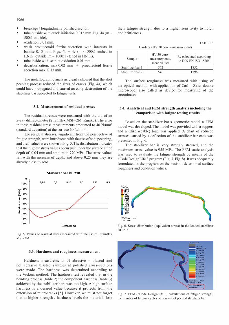
Based on the stabilizer bar’s geometric model a FeM model was developed. The model was provided with a support and a (displaceable) load was applied. A chart of reduced stresses caused by a deflection of the stabilizer bar ends was presented in Fig. 6.
The stabilizer bar is very strongly stressed, and the maximum stress value is 955 MPa. The FEM static analysis was used to evaluate the fatigue strength by means of the nCode Designlife 8 program (Fig. 7, Fig. 8). it was adequately formulated in the program on the basis of determined surface roughness and condition values.
Fig. 6. Stress distribution (equivalent stress) in the loaded stabilizer DC 218
Fig. 7. FeM (nCode Designlife 8) calculations of fatigue strength, the number of fatigue cycles of non – shot peened stabilizer bar

1967
Fig.8. FeM (nCode Designlife 8) calculations of fatigue strength, the number of fatigue cycles of shot peened stabilizer bar
The values obtained using the Franke 1 and 2 eccentric fatigue machine confirmed the results of analytical calculations (Fig. 9).
Fig. 9. Comparison of fatigue strength based on the tests (Franke) and simulation (nCode Designlife)
The use of 0.4 mm and 0.7 mm steel grit causes an increase of the lifespan of the abrasive blasting grit (Fig. 7 – 9). It is to be attributed to the surface smoothing and the introduction of near – surface compressive residual stress in the surface zone. In addition, the tendency to a higher lifespan in case of a higher surface coverage with the finer abrasive blasting grit was observed.
4. conclusions
1. We proved in this paper that it was possible to use the FEM for a preliminary assessment of the fatigue strength. The results of numerical analyses proved to be correct also in the fatigue tests carried out on real stabilizer bars.
2. We showed that the shot peening of a highly stressed tubular stabilizer bar led to a considerable increase of the fatigue strength. Through the controlled shot peening, the increases of fatigue strength up to 120 % in comparison to the corresponding not abrasive – blasted condition were possible.
3. Microcracks which formed in the bending process were smoothed though the shot peening or their size was considerably reduced.
4. The shot peening inside a stabilizer bar (in case of tubular stabilizer bars) ensures the removal of microcracks and
impurities forming during the manufacturing process.5. The shot peening process is expensive and requires
special equipment in the stabilizer bar manufacturing process. As a result, the duration of the technological and manufacturing process is extended. This leads in consequence to a considerable increase of the final product price.
6. The surface of a shot-peened stabilizer bar is better prepared for painting. The paint applied during the painting process is subjected to a stronger bonding, thus the stabilizer bar surface is more resistant to the aggressive action of the „media” during the operation of a motor vehicle.
reFerenCes
[1] a.M. Wittek. Wpływ czynników konstrukcyjnych i technologicznych na trwałość stabilizatorów w pojazdach samochodowych. phD thesis. silesian university of Technology. katowice (2013).
[2] a. stenico. Werkstoffmechanische untersuchungen zur zahnfußtragfähigkeit einsatzgehärteter zahnräder. phD thesis. Technische universität München (2007).
[3] y.k. Gao. improvement of fatigue property in 7050 – T7451 aluminum alloy by laser peening and shot peening. Materials Science and Engineering A 528, 3823–3828 (2011).
[4] s. Bagherifard, i. Fernandez-pariente, r. Ghelichi, M. Guagliano. Fatigue behavior of notched steel specimens with nanocrystallized surface obtained by severe shot peening. Materials and Design 45, 497 – 503 (2013).
[5] j. Davis. analytical Modeling and applications of residual stresses induced by shot peening. phD thesis. university of Washington (2012).
[6] p. zhang , j. lindemann. influence of shot peening on high cycle fatigue properties of the high-strength wrought magnesium alloy az80. scripta Materialia 52, 485 – 490 (2005).
[7] k.l. johnson. Contact Mechanics. Cambridge university Press (1985).
[8] W. Duoj, k. li, y. Mei. Mechanical approach to the residual stress field induced by shot peening. Materials science and Engineering, 147(2), 167 – 173 (1991).
[9] j. liu. numerical analysis for effects of shot peening on fatigue crack growth. international journal of Fatigue 50, 101 – 108 (2013).
[10] X. song, W.C. liu, j.p. Belnoue, j. Dong, G.h. Wu, W.j. Ding, s.a.j. kimber, T. Buslaps, a.j.G. lunt, a.M. korsunsky. an eigenstrain-based finite element model and the evolution of shot peening residual stresses during fatigue of GW103 magnesium alloy. international journal of Fatigue 42, 284 – 295 (2012).
[11] h.y. Miao, s. larose, C. perron, M. lévesque. on the potential applications of a 3D random finite element model for the simulation of shot peening. Advances in Engineering Software 40, 1023–1038 (2009).
[12] a. Gariépy, s. larose, C. perron, M. lévesque. shot peening and peen forming finite element modelling – Towards a quantitative method. international journal of solids and Structures 48 2859–2877 (2011).
[13] S. Tekeli. Enhancement of fatigue strength of SAE 9245 steel

1968
by shot peening. Materials letters 57, 604–608 (2002).[14] M.a.s. Torres, h.j.C. voorwald. an evaluation of shot
peening, residual stress and stress relaxation on the fatigue life of aisi 4340 steel. international journal of Fatigue 24, 877–886 (2002).
[15] a. Molinari, e. santuliana, i. Cristofolini, a. rao, s. libardi, p. Marconi. surface modifications induced by shot peening and their effect on the plane bending fatigue strength of a Cr – Mo steel produced by powder metallurgy. Materials Science and Engineering A 528, 2904–2911 (2011).
[16] k.a. soady, B.G. Mellor, j. shackleton, a. Morris, p.a.s.
reed: The effect of shot peening on notched low cycle fatigue. Materials Science and Engineering A 528, 8579– 8588 (2011).
[17] S. Daichendt. Relaxation strahlbedingter Eigenspannungen unter kombiniert thermisch–mechanischer Beanspruchung in laserstrahl – schweißverbindungen einer alsiMgCu– knetlegierung. phD thesis. universität kassel, kassel (2011).
[18] r. herzog, W. zinn, B. scholtes. zur aussagefähigkeit der almenintensität als kennwert bei der gezielten Eigenspannungserzeugung durch kugelstrahlen. Mat. –wiss. u. Werkstofftech. 27, s. 608 – 617, vCh verlagsgesellschaft, Weinheim, (1996).