doe-std-1027-92; hazard categorization and accident analysis techniques ... 1992_haza… · hazard...
TRANSCRIPT

TS
NOT MEASUREMENTSENSITIVE
DOE-STD-1027-92December 1992
CHANGE NOTICE NO.1September 1997
DOE STANDARD
HAZARD CATEGORIZATION AND ACCIDENT ANALYSIS TECHNIQUES FOR COMPLIANCE WITH DOE ORDER 5480.23, NUCLEAR SAFETY ANALYSIS REPORTS
U.S. Department of Ener gy AREA SAFTWashin gton, D.C. 20585
DISTRIBUTION STATEMENT A. Approved for public release; distribution is unlimited.
This document has been reproduced directly from the best available copy.
Available to DOE and DOE contractors from the Office of Scientific and TechnicalInformation, P.O. Box 62, Oak Ridge, TN 37831; (423) 576-8401.
Available to the public from the U.S. Department of Commerce, TechnologyAdministration, National Technical Information Service, Springfield, VA 22161; (703) 487-4650.
Order No. DE98001283
Change Notice No. 1 DOE-STD-1027-92
1
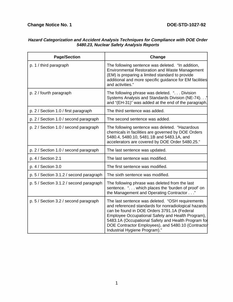
Hazard Cate gorization and Accident Anal ysis Techniques for Compliance with DOE Order5480.23, Nuclear Safet y Anal ysis Reports
Page/Section Chan ge
p. 1 / third paragraph The following sentence was deleted. “In addition,Environmental Restoration and Waste Management(EM) is preparing a limited standard to provideadditional and more specific guidance for EM facilitiesand activities.”
p. 2 / fourth paragraph The following phrase was deleted. “. . . DivisionSystems Analysis and Standards Division (NE-74). . .”and “(EH-31)” was added at the end of the paragraph.
p. 2 / Section 1.0 / first paragraph The third sentence was added.
p. 2 / Section 1.0 / second paragraph The second sentence was added.
p. 2 / Section 1.0 / second paragraph The following sentence was deleted. “Hazardouschemicals in facilities are governed by DOE Orders5480.4, 5480.10, 5481.1B and 5483.1A, andaccelerators are covered by DOE Order 5480.25.”
p. 2 / Section 1.0 / second paragraph The last sentence was updated.
p. 4 / Section 2.1 The last sentence was modified.
p. 4 / Section 3.0 The first sentence was modified.
p. 5 / Section 3.1.2 / second paragraph The sixth sentence was modified.
p. 5 / Section 3.1.2 / second paragraph The following phrase was deleted from the lastsentence. “. . . which places the ‘burden of proof’ onthe Management and Operating Contractor . . .”
p. 5 / Section 3.2 / second paragraph The last sentence was deleted. “OSH requirementsand referenced standards for nonradiological hazardscan be found in DOE Orders 3791.1A (FederalEmployee Occupational Safety and Health Program),5483.1A (Occupational Safety and Health Program forDOE Contractor Employees), and 5480.10 (ContractorIndustrial Hygiene Program).”
Change Notice No. 1 DOE-STD-1027-92
Page/Section Chan ge
2
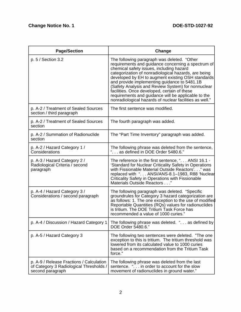
p. 5 / Section 3.2 The following paragraph was deleted. “Otherrequirements and guidance concerning a spectrum ofchemical safety issues, including hazardcategorization of nonradiological hazards, are beingdeveloped by EH to augment existing OSH standardsand provide implementing guidance to 5481.1B(Safety Analysis and Review System) for nonnuclearfacilities. Once developed, certain of theserequirements and guidance will be applicable to thenonradiological hazards of nuclear facilities as well.”
p. A-2 / Treatment of Sealed Sources The first sentence was modified.section / third paragraph
p. A-2 / Treatment of Sealed Sources The fourth paragraph was added.section
p. A-2 / Summation of Radionuclide The “Part Time Inventory” paragraph was added.section
p. A-2 / Hazard Category 1 / The following phrase was deleted from the sentence,Considerations “. . . as defined in DOE Order 5480.6.”
p. A-3 / Hazard Category 2 / The reference in the first sentence, “. . . ANSI 16.1 -Radiological Criteria / second ‘Standard for Nuclear Criticality Safety in Operationsparagraph with Fissionable Material Outside Reactors’. . .” was
replaced with “. . . ANSI/ANS-8.1–1983, R88 ‘NuclearCriticality Safety in Operations with FissionableMaterials Outside Reactors . . .”
p. A-4 / Hazard Category 3 / The following paragraph was deleted. “SpecificConsiderations / second paragraph groundrules for Category 3 hazard categorization are
as follows: 1. The one exception to the use of modifiedReportable Quantities (RQs) values for radionuclidesis tritium. The DOE Tritium Task Force hasrecommended a value of 1000 curies.”
p. A-4 / Discussion / Hazard Category 1 The following phrase was deleted. “. . . as defined byDOE Order 5480.6.”
p. A-5 / Hazard Category 3 The following two sentences were deleted. "The oneexception to this is tritium. The tritium threshold waslowered from its calculated value to 1000 curies based on a recommendation from the Tritium Taskforce."
p. A-9 / Release Fractions / Calculation The following phrase was deleted from the lastof Category 3 Radiological Thresholds / sentence. “. . . in order to account for the slowsecond paragraph movement of radionuclides in ground water.”

Change Notice No. 1 DOE-STD-1027-92
Page/Section Chan ge
3
p. A-9 / Release Fractions / Calculation This paragraph was added.of Category 3 Radiological Thresholds /third paragraph
p. A-10 / Table A.1 Isotope H-3, Category 3 Curies entry changed to1.6E+04* from 1.0E+03*. Threshold Grams (column 4)entry changed to 1.6E+00* from 1.0E�01*.
p. A-10 / Table A.1 Isotope P-32, Category 2 Curies entry changed to4.4E+03 from 4.4E+01.
p. A-10 / Table A.1 Isotope P-32, acid**, Category 2 Curies entry changedto 2.2E+06 from 2.2E+04.
p. A-10 / Table A.1 Isotope Mn-52, Category 2 Curies entry changed to4.0E+06 from 1.8E+07. Threshold Grams (column 2)entry changed to 8.8E+00 from 3.9E+01.
p. A-10 / Table A.1 Isotope Se-75, Category 2 Curies entry changed to3.4E+05 from 3.4E+06. Threshold Grams (column 2)entry changed to 2.4E+01 from 2.4E+02.
p. A-11 / Table A.1 Isotope Sb-126, Threshold Grams (column 2) entry changed to 3.0E+01 from 3.0E+00. Threshold Grams(column 4) changed to 3.4E�03 from 3.4E�04.
p. A-11 / Table A.1 Isotope Te-127m, Threshold Grams (column 2) entrychanged to 1.6E+01 from 1.6E�01. Threshold Grams(column 4) entry changed to 4.2E�02 from 4.2E�04.
p. A-11 / Table A.1 Isotope Pm-147, Threshold Grams (column 2) entrychanged to 9.0E+02 from 8.0E+02.
p. A-11 / Table A.1 Isotope Hg-203, Threshold Grams (column 2) entrychanged to 3.1E+01 from 3.1E+00. Threshold Grams(column 4) entry changed to 2.6E�02 from 2.6E�03.
p. A-11 / Table A.1 Isotope Bi-207, Category 2 Curies entry changed to2.2E+06 from 1.9E+06. Threshold Grams entry(column 2) changed to 4.3E+04 from 3.8E+04. Threshold Grams (column 4) entry changed to1.1E+01 from 9.7E+00.
p. A-12 / Table A.1 Isotope Cf-252, Category 2 Curies entry changed to2.2E+02 from 3.0E+02. Threshold Grams (column 2)entry changed to 4.1E�01 from 7.0E�01. ThresholdGrams (column 4) entry changed to 5.9E�03 from2.2E�04.
p. A-12 / Table A.1, footnote 1 New information added.

Change Notice No. 1 DOE-STD-1027-92
Page/Section Chan ge
4
p. A-12 / Table A.1, footnote 2 New information added.
p. A-12 / Table A.1, single asterisk New information added.
Concluding Material Preparing Activity updated.

DOE-STD-1027-92
iii
FOREWORD
The purpose of this DOE Standard is to establish guidance for facility managers and ProgramSecretarial Officers (PSOs) and thereby help them to comply consistently and more efficientlywith the requirements of DOE Order 5480.23, Nuclear Safety Analysis Reports. To this end, thisguidance provides the following practical information:
1) The threshold quantities of radiological material inventory below which compliance withDOE Order 5480.23 is not required.
2) The level of effort to develop the program plan and schedule required in Section 9.b.(2)of the Order, and information for making a preliminary assessment of facility hazards.
3) A uniform methodology for hazard categorization under the Order.
4) Insight into the “graded approach” for SAR development, especially in hazardassessment and accident analysis techniques.
Individual PSOs may develop additional guidance addressing safety requirements for facilitieswhich fall below the threshold quantities specified in this document.

DOE-STD-1027-92
iv
INTENTIONALLY BLANK
DOE-STD-1027-92
v
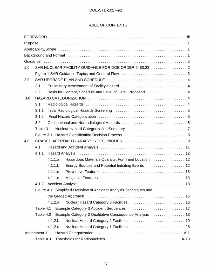
TABLE OF CONTENTS
FOREWORD . . . . . . . . . . . . . . . . . . . . . . . . . . . . . . . . . . . . . . . . . . . . . . . . . . . . . . . . . . . . . . . . . iii
Purpose . . . . . . . . . . . . . . . . . . . . . . . . . . . . . . . . . . . . . . . . . . . . . . . . . . . . . . . . . . . . . . . . . . . . . 1
Applicability/Scope . . . . . . . . . . . . . . . . . . . . . . . . . . . . . . . . . . . . . . . . . . . . . . . . . . . . . . . . . . . . . 1
Background and Format . . . . . . . . . . . . . . . . . . . . . . . . . . . . . . . . . . . . . . . . . . . . . . . . . . . . . . . . 1
Guidance . . . . . . . . . . . . . . . . . . . . . . . . . . . . . . . . . . . . . . . . . . . . . . . . . . . . . . . . . . . . . . . . . . . . 2
1.0 SAR NUCLEAR FACILITY GUIDANCE FOR DOE ORDER 5480.23 . . . . . . . . . . . . . . . . 2
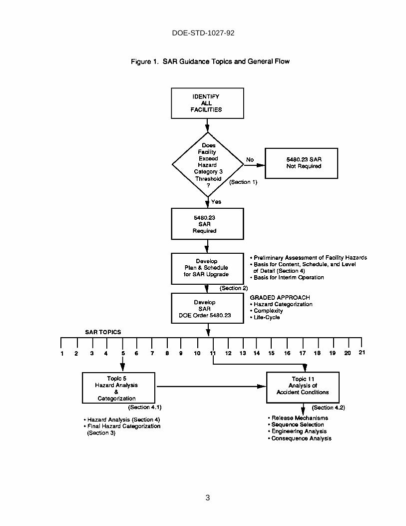
Figure 1 SAR Guidance Topics and General Flow . . . . . . . . . . . . . . . . . . . . . . . . . . . . . . . 3
2.0 SAR UPGRADE PLAN AND SCHEDULE . . . . . . . . . . . . . . . . . . . . . . . . . . . . . . . . . . . . . . 4
2.1 Preliminary Assessment of Facility Hazard . . . . . . . . . . . . . . . . . . . . . . . . . . . . . . . 4
2.2 Basis for Content, Schedule and Level of Detail Proposed . . . . . . . . . . . . . . . . . . . 4
3.0 HAZARD CATEGORIZATION . . . . . . . . . . . . . . . . . . . . . . . . . . . . . . . . . . . . . . . . . . . . . . . 4
3.1 Radiological Hazards . . . . . . . . . . . . . . . . . . . . . . . . . . . . . . . . . . . . . . . . . . . . . . . . 4
3.1.1 Initial Radiological Hazards Screening . . . . . . . . . . . . . . . . . . . . . . . . . . . . . . . . . . 5
3.1.2 Final Hazard Categorization . . . . . . . . . . . . . . . . . . . . . . . . . . . . . . . . . . . . . . . . . . 5
3.2 Occupational and Nonradiological Hazards . . . . . . . . . . . . . . . . . . . . . . . . . . . . . . 5
Table 3.1 Nuclear Hazard Categorization Summary . . . . . . . . . . . . . . . . . . . . . . . . . . . . 7
Figure 3.1 Hazard Classification Decision Process . . . . . . . . . . . . . . . . . . . . . . . . . . . . . . 8
4.0 GRADED APPROACH - ANALYSIS TECHNIQUES . . . . . . . . . . . . . . . . . . . . . . . . . . . . . 9
4.1 Hazard and Accident Analysis . . . . . . . . . . . . . . . . . . . . . . . . . . . . . . . . . . . . . . . . 11
4.1.1 Hazard Analysis . . . . . . . . . . . . . . . . . . . . . . . . . . . . . . . . . . . . . . . . . . . . . . . . . . . 12
4.1.1.a Hazardous Materials Quantity, Form and Location . . . . . . . . . . . . . . . 12
4.1.1.b Energy Sources and Potential Initiating Events . . . . . . . . . . . . . . . . . . 12
4.1.1.c Preventive Features . . . . . . . . . . . . . . . . . . . . . . . . . . . . . . . . . . . . . . . 13
4.1.1.d Mitigative Features . . . . . . . . . . . . . . . . . . . . . . . . . . . . . . . . . . . . . . . . 13
4.1.2 Accident Analysis . . . . . . . . . . . . . . . . . . . . . . . . . . . . . . . . . . . . . . . . . . . . . . . . . . 13
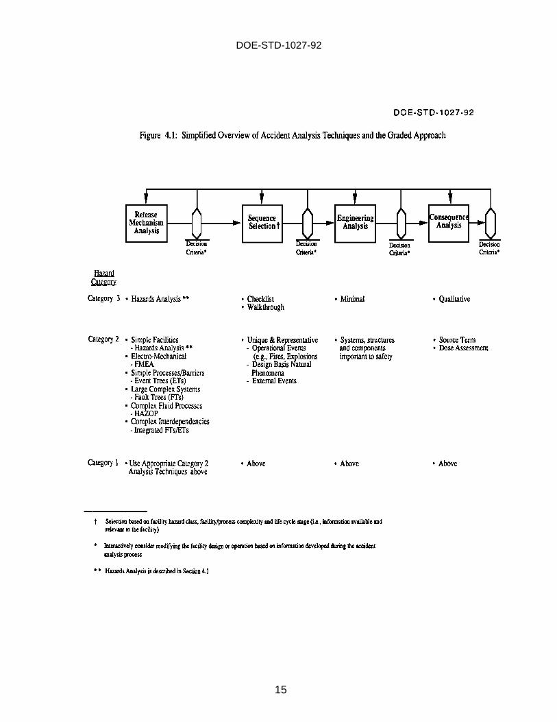
Figure 4.1 Simplified Overview of Accident Analysis Techniques and
the Graded Approach . . . . . . . . . . . . . . . . . . . . . . . . . . . . . . . . . . . . . . . . . . . . . . 15
4.1.2.a Nuclear Hazard Category 3 Facilities . . . . . . . . . . . . . . . . . . . . . . . . . 16
Table 4.1 Example Category 3 Accident Sequences . . . . . . . . . . . . . . . . . . . . . . . . . . . 17
Table 4.2 Example Category 3 Qualitative Consequence Analysis . . . . . . . . . . . . . . . . 18
4.1.2.b Nuclear Hazard Category 2 Facilities . . . . . . . . . . . . . . . . . . . . . . . . . . 19
4.1.2.c Nuclear Hazard Category 1 Facilities . . . . . . . . . . . . . . . . . . . . . . . . . . 25
Attachment 1 Hazard Categorization . . . . . . . . . . . . . . . . . . . . . . . . . . . . . . . . . . . . . . . . . A-1
Table A.1 Thresholds for Radionuclides . . . . . . . . . . . . . . . . . . . . . . . . . . . . . . . . . . . A-10
DOE-STD-1027-92
vi
INTENTIONALLY BLANK
DOE-STD-1027-92
1
Purpose
The purpose of this DOE Standard is to establish guidance for the preparation and review ofhazard categorization and accident analyses techniques as required in DOE Order 5480.23,Nuclear Safety Analysis Reports. This new Order requires further guidance to ensureconsistency across all nuclear facilities within the DOE complex. This DOE Standard imposesno new requirements on nuclear facilities. Instead, it focuses on (1) the definition of thestandard identifying nuclear facilities required to have SARs in order to comply with the Order,(2) the SAR implementation plan and schedule, (3) the hazard categorization methodology to beapplied to all facilities, and (4) the accident analysis techniques appropriate for the gradedapproach addressed in the Order. DOE Order 5480.23 and its attached guidance documentprovide some direction on the use of the graded approach. This report is intended not tosupersede that direction, but to supplement and clarify it. Methods other than those suggestedin this guide may be considered for applying the graded approach, but they must be justifiedwhenever grading is applied.
Applicability/Scope
This DOE Standard is to be used with DOE Order 5480.23 and may not be applicable to otherDOE Orders. Regarding the applicability of other nuclear safety Orders to those facilitieswhich fall below category 3 criteria, as defined by this standard, the PSOs shall provideguidance, as appropriate.
Developed by a working group with contributions from all Secretarial and oversightorganizations having nuclear safety responsibilities, with input from several field andcontractor organizations, and with clarifying direction from the Senior Nuclear Managersmeeting of October 26, 1992, this standard applies to DOE nuclear facilities as defined in theOrder and is suitable for DOE nuclear facilities.
Background and Format
The Department of Energy (DOE) has the responsibility to establish rules, regulations, andOrders as necessary to protect health or to minimize danger to life or property. In carrying out this responsibility, DOE has issued Order 5480.23, Nuclear Safety Analysis Reports. This Order specifies requirements for safety analyses involving DOE nuclear facilities, and for submittal, review, and approval of contractor plans and programs to meet theserequirements.
This document provides specific guidance on several of the requirements contained in this Order. Section 1 establishes the threshold quantities of hazardous materials which, if exceeded, wouldmandate the development of a SAR under this Order. Section 2 discusses the SAR upgrade planand schedule which must to be submitted to each PSO. Section 3 provides a uniform

DOE-STD-1027-92
2
methodology for hazard categorization. Finally, Section 4 gives additional specific guidance onthe use of the graded approach and accident/hazard analysis techniques for compliance with thisOrder.
Figure 1 portrays the relationships between the Order and the topics covered in this guidancedocument.
Questions regarding this standard should be addressed to the Director, Office of Nuclear SafetyPolicy & Standards (EH-31).
Guidance
1.0 SAR NUCLEAR FACILITY GUIDANCE FOR DOE ORDER 5480.23
Order 5480.23 defines the “level of concern” within the framework of HazardCategorization, which requires the preparation of a SAR for DOE nuclear facilities. Section 3 and Attachment 1 of this Standard provide consistent guidance on facilitycategorization. All facilities classified as at least Category 3 in accordance with thisguidance are required to comply with DOE Order 5480.23. Additional guidanceregarding some environmental restoration activities is provided in an InterpretationMemo dated June 9, 1997, Black to Psaras. Facilities that do not meet or exceedCategory 3 threshold criteria but still possess some amount of radioactive material maybe considered Radiological Facilities.
Radiological Facilities are exempt from this Order, but they are not exempt from othersafety requirements. 10 CFR 835 applies for all facilities including those that areexempt from DOE Order 5480.23. Exemption from the requirements of 5480.23 doesnot excuse contractors from doing analysis, where applicable, to evaluate potentialsignificant radiation exposures to workers. For example, EM has prepared a limitedstandard to provide additional and more specific guidance regarding measuresnecessary to ensure safety for EM facilities and activities below category 3 criteria(DOE-EM-STD-5502-94).
DOE-STD-1027-92
3
DOE-STD-1027-92
4
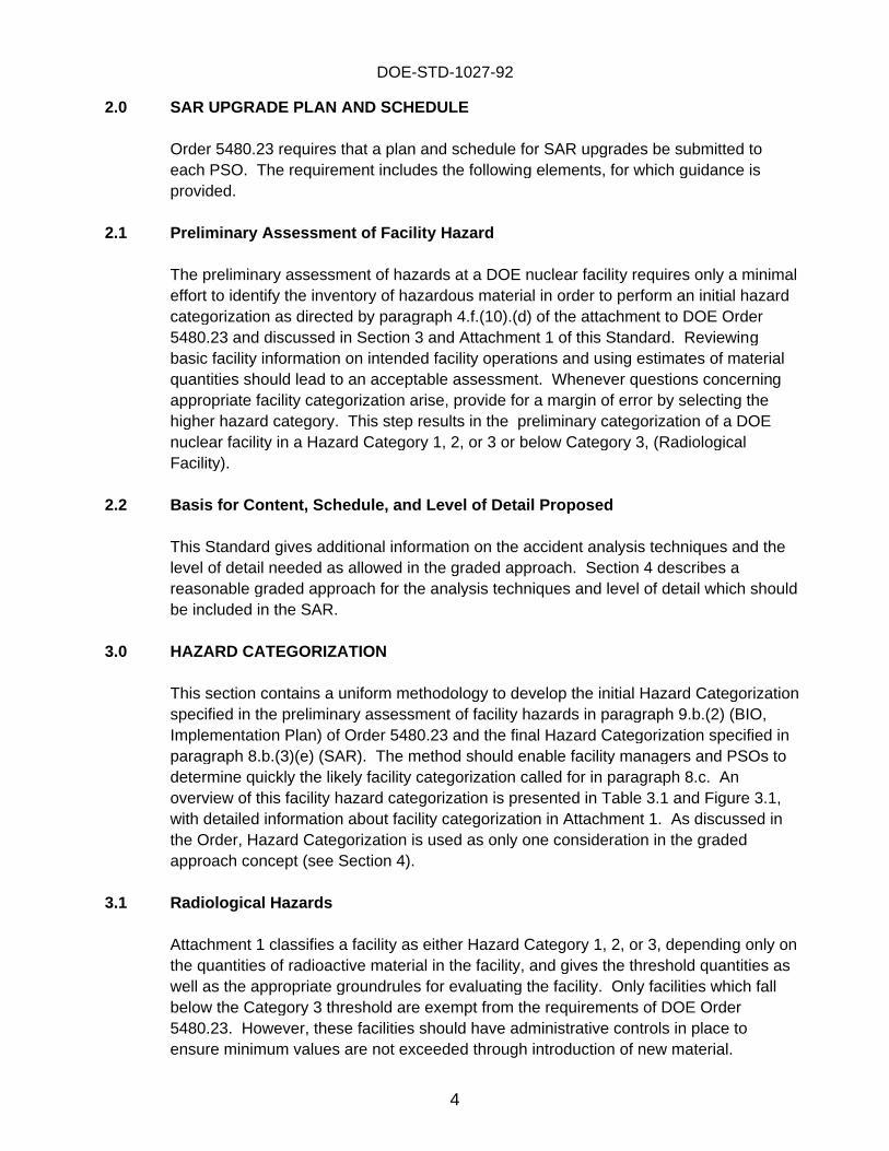
2.0 SAR UPGRADE PLAN AND SCHEDULE
Order 5480.23 requires that a plan and schedule for SAR upgrades be submitted toeach PSO. The requirement includes the following elements, for which guidance isprovided.
2.1 Preliminar y Assessment of Facilit y Hazard
The preliminary assessment of hazards at a DOE nuclear facility requires only a minimaleffort to identify the inventory of hazardous material in order to perform an initial hazardcategorization as directed by paragraph 4.f.(10).(d) of the attachment to DOE Order5480.23 and discussed in Section 3 and Attachment 1 of this Standard. Reviewingbasic facility information on intended facility operations and using estimates of materialquantities should lead to an acceptable assessment. Whenever questions concerningappropriate facility categorization arise, provide for a margin of error by selecting thehigher hazard category. This step results in the preliminary categorization of a DOEnuclear facility in a Hazard Category 1, 2, or 3 or below Category 3, (RadiologicalFacility).
2.2 Basis for Content, Schedule, and Level of Detail Proposed
This Standard gives additional information on the accident analysis techniques and thelevel of detail needed as allowed in the graded approach. Section 4 describes areasonable graded approach for the analysis techniques and level of detail which shouldbe included in the SAR.
3.0 HAZARD CATEGORIZATION
This section contains a uniform methodology to develop the initial Hazard Categorizationspecified in the preliminary assessment of facility hazards in paragraph 9.b.(2) (BIO,Implementation Plan) of Order 5480.23 and the final Hazard Categorization specified inparagraph 8.b.(3)(e) (SAR). The method should enable facility managers and PSOs todetermine quickly the likely facility categorization called for in paragraph 8.c. Anoverview of this facility hazard categorization is presented in Table 3.1 and Figure 3.1,with detailed information about facility categorization in Attachment 1. As discussed inthe Order, Hazard Categorization is used as only one consideration in the gradedapproach concept (see Section 4).
3.1 Radiolo gical Hazards
Attachment 1 classifies a facility as either Hazard Category 1, 2, or 3, depending only onthe quantities of radioactive material in the facility, and gives the threshold quantities aswell as the appropriate groundrules for evaluating the facility. Only facilities which fallbelow the Category 3 threshold are exempt from the requirements of DOE Order5480.23. However, these facilities should have administrative controls in place toensure minimum values are not exceeded through introduction of new material.

DOE-STD-1027-92
5
3.1.1 Initial Radiolo gical Hazards Screenin g
The radiological hazards screening enables facility managers to determine quickly thelikely facility categorization required in paragraph 8.c. This process is to provide aninitial screening of the potential hazards represented by a facility. It should be used forpreliminary assessment of facility hazards in “plans and schedules” for proposedupgrades to SARs when a Hazards Analysis (see Section 4) has not been performed. An overview of the radiological hazards screening is provided in Table 3.1 and Figure3.1.
3.1.2 Final Hazard Cate gorization
Once a Hazards Analysis has been performed as defined in Section 4, the hazardcategorization can be finalized. The final categorization is based on an “unmitigatedrelease” of available hazardous material. For the purposes of hazard categorization,“unmitigated” is meant to consider material quantity, form, location, dispersibility andinteraction with available energy sources, but not to consider safety features (e.g.,ventilation system, fire suppression, etc.) which will prevent or mitigate a release.
The Hazards Analysis (or other existing safety analyses) provides an understanding ofthe material which can physically be released from the facility. This inventory should becompared against the Threshold Quantities (TQs) identified in Attachment 1. Theairborne release fractions used in generating the TQ values for Category 2 in Table A.1are provided on Page A-9 of Attachment 1. As discussed in the attachment, these areintended to be generally conservative for a broad range of possible situations. Therefore, the inventory values of Table A.1 may be used directly for determination asto whether a facility exceeds Category 2. Alternatively, for final Categorization, forfacilities initially classified as Hazard Category 2, if the credible release fractions can beshown to be significantly different than these values based on physical and chemicalform and available dispersive energy sources, the threshold inventory values forCategory 2 in Table A.1 may be divided by the ratio of the maximum potential releasefraction to that found on Page A-9. All assumptions which are used to reduce theinventory at risk should be supported in the Hazards Analysis. This also applies toground rules identified in Attachment 1, to demonstrate that the ground rule conditionsexist.
3.2 Occupational and Nonradiolo gical Hazards
DOE Order 5480.23 places new emphasis on already existing requirements concerningthe protection of workers, the public, and the environment against all hazards. Theorder not only requires the analysis of radiological hazards, but also requires that theanalysis and safety basis of occupational and nonradiological hazards be documented inthe SAR.

DOE-STD-1027-92
6
Occupational hazards, including common industrial hazards, that are identified in thehazards analysis and that are clearly regulated by DOE-prescribed occupational safetyand health (OSH) standards should be segregated from non-routine hazards. Nospecific SAR analyses will be required for these hazards; however, analyses required bythe OSH standards should be referenced, and all applicable OSH standards listed in theSAR.
The balance of the hazards that are not covered by OSH regulations and that presentsignificant, non-routine concerns to workers, the public, or the environment shouldundergo the hazard and accident analysis as summarized in Section 4.1.
For chemical hazards covered by 29 CFR 1910.119 (Process Safety Management(PSM) Rule), the SAR should reference all analyses and summarize their significantfindings. When analyses of chemical hazards show the potential for significant off-siteconsequences, then the requirements of 29 CFR 1910.119 may apply regardless of thetype or quantity of chemical involved. The Office of Environment, Safety, and Health(EH) has developed implementing guidance and training to assure adequate compliancewith the PSM rule.
Any nonradiological hazard that acts to initiate, or increase the consequences of, aradiological scenario should be fully analyzed as part of that scenario.
DOE-STD-1027-92
7
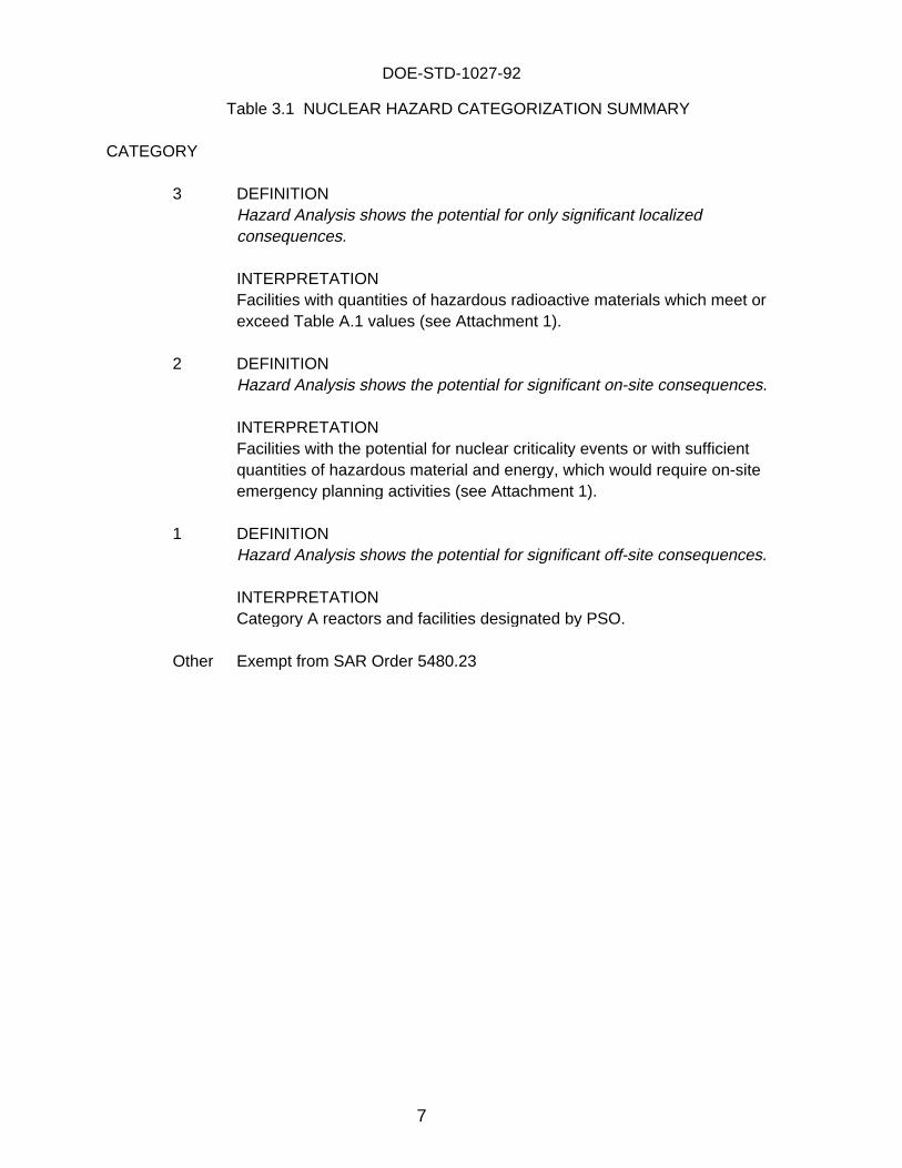
Table 3.1 NUCLEAR HAZARD CATEGORIZATION SUMMARY
CATEGORY
3 DEFINITIONHazard Analysis shows the potential for only significant localizedconsequences.
INTERPRETATIONFacilities with quantities of hazardous radioactive materials which meet orexceed Table A.1 values (see Attachment 1).
2 DEFINITIONHazard Analysis shows the potential for significant on-site consequences.
INTERPRETATIONFacilities with the potential for nuclear criticality events or with sufficientquantities of hazardous material and energy, which would require on-siteemergency planning activities (see Attachment 1).
1 DEFINITIONHazard Analysis shows the potential for significant off-site consequences.
INTERPRETATIONCategory A reactors and facilities designated by PSO.
Other Exempt from SAR Order 5480.23

DOE-STD-1027-92
8
DOE-STD-1027-92
9
4.0 GRADED APPROACH - ANALYSIS TECHNIQUES
Order 5480.23 states that a graded approach is to be used in the preparation of SARsfor nuclear facilities.
Graded Approach Objective
The objective of a graded approach is to proportion SAR requirements for analysis,evaluation, and documentation to the potential hazards associated with operating DOEnuclear facilities. The level of understanding and control of hazards to workers, thepublic, and the environment will be comparable for all facilities. For relatively simplefacilities, an acceptable level of understanding and control of hazards can be achievedwith less sophisticated techniques and less detailed knowledge of facilitycharacteristics than those required for more complex facilities.
The anticipated effect of applying the graded approach is that competing resources willbe used more efficiently and produce maximum benefit. As a result, SARs for complex,higher-hazard facilities would be expected to use more resources in meeting therequirements than SARs for simple, lower-hazard facilities. The expectation of thegreater expenditure of resources for SARs for complicated, higher-hazard facilities is notmeant to imply that a lower level of safety or attentiveness is acceptable for simple,lower-hazard facilities. Regardless of hazard and complexity of a facility, adequatesafety analysis, evaluation, and supporting documentation must be provided.
The graded approach should be used to eliminate unproductive or unnecessaryfeatures or activities which add to the costs of implementation, narrow the envelope ofpermissible operation, or make the facility management unnecessarily ponderous orburdensome. It does not relieve the contractor or the responsible manager or PSOfrom the obligation to maintain and operate the facility safely and efficiently. Requirements which conflict with this responsibility should be brought to the attention ofthe appropriate DOE management.
This document provides the guidelines for a graded approach to development of theanalysis techniques which should be used in the SAR. This is the first step to thegraded approach for safety analysis of DOE facilities. The analysis techniquesdescribed below are useful in the Hazard Analysis Section and the Accident AnalysisSection of the SAR. These sections discuss the analysis expected for various types offacilities.
The primary objective of the graded approach to the accident analysis is to select andapply a rigorous analysis technique which provides sufficient detail to assess eachpostulated accident or failure, the resulting consequences, and all means of preventionor mitigation. The choice of the technique should be defensible and producemeaningful results.
DOE-STD-1027-92
10
In general, a graded approach dictates a more rigorous and more thoroughlydocumented analysis and evaluation of higher-hazard facilities than lower-hazardfacilities, given the potential for more widespread and severe consequences if a higher-hazard facility fails to meet its safety basis requirements. In all cases, however, theSAR must provide adequate safety analysis, evaluation, and supportingdocumentation. The Order provides direction on how the graded approach is to beapplied to the SAR. The level of effort, sophistication of analysis, and thethoroughness of documentation are to be graded or proportioned commensurate withthe considerations listed below:
(1) The magnitude of the hazards being addressed
(2) The complexity of both the facility and/or the safety systems relied on tomaintain an acceptable level of risk
(3) The stage or stages of the facility life cycle
Magnitude of the hazards
The Order states that contractors shall be required to perform a Hazard Analysis oftheir nuclear activities and to classify their processes, operations, or activities. On thebasis of that analysis, they shall evaluate and classify the consequences of unmitigatedreleases of hazardous radioactive and chemical material in the following categories:
Category 1 Hazard: The Hazard Analysis shows the potential for significant off-siteconsequences.
Category 2 Hazard: The Hazard Analysis shows the potential for significant on-siteconsequences.
Category 3 Hazard: The Hazard Analysis shows the potential for only significantlocalized consequences.
The hazard categorization process provides a method for assessing potential hazardsand does not consider potential risk. Section 3 and Attachment 1 provide detailedguidance on a consistent methodology which should be used for hazard categorization.
Complexity of the Facility and/or its Safety Systems
The graded approach directs that the effort should be proportional to the complexity ofthe facility and the safety systems relied on to maintain an acceptable level of risk. Simple facilities would require less sophisticated analysis. Consequently, thesophistication of the information to be provided in the SAR would be proportionedaccordingly. In many cases, the complexity of a facility may have a greater impact onthe grading of effort than the hazard categorization.

DOE-STD-1027-92
11
In evaluating complexity, the SAR should consider the complexity of the person-machine interface as well as the design and hardware of a facility. The preferredapproach is to provide for safety through engineered safeguards and not to rely onadministrative controls for safety. However, if the safety of the facility depends moreheavily on personnel to initiate, control, or perform safety functions than on the use ofautomated safety devices, then the procedures and training of operators warrant moredetailed discussion in the SAR.
The remainder of this Standard provides additional guidance on the relationshipbetween complexity and the analysis techniques which are to be used in the SAR.
Facility’s Stage in its Life-Cycle
The third consideration is the stage or stages of the facility life cycle for which SARapproval is sought. For a new facility, the SAR covers the commitments for facilitydesign and construction. For a facility which merely seeks authorization to continueoperations, the SAR need not elaborate on completed phases of the project. Information about safety decisions previously made, such as site selection, should bedeveloped only to support current and anticipated safety decisions. A SAR for afacility near the end of its operating life and unlikely to be modified before retirementneed not develop safety engineering bases with the thoroughness expected of a SARfor a facility which may be modified or extended in the future. When modifications areperformed or the facility mission is extended or changed, additional detail to support thejustification for the design adequacy will be required. For a facility which is partly shutdown and is used for only limited functions, the SAR should develop the basis forconfidence in the safety of the inactive portions of the facility and the safety basis forthe intended operations. The inactive portion of a facility should be evaluated to ensurethat the risks from the residual hazards (e.g., contamination, hazardous materialinventory) are evaluated and controlled.
All SARs should furnish information about subsequent stages of the facility life cyclebeyond that stage for which approval is sought, including end-of-life decontaminationand decommissioning. However, SARs need to develop this information only enoughto demonstrate that adequate attention is being given to anticipated future safetyproblems. For facilities which are approaching decommissioning, the emphasis shouldbe on these remaining activities. Documentation provided on the operations beingphased out should be the minimum necessary to demonstrate the safety of the facilityduring its remaining operating life, and future decontamination and decommissioningactivities.
4.1 Hazard and Accident Anal ysis
The Hazard Analysis process consists of the identification of the relative and absolutehazards of the materials in a facility. The objective is to focus the safety assessmenteffort on those hazards which have the potential to present significant, non-routineconcerns to the worker, the public, and the environment.

DOE-STD-1027-92
12
4.1.1 Hazard Anal ysis
Hazard Analysis is the initial step in the process of identifying and evaluating potentialaccidents in a facility. It is used to identify the hazardous chemical or radioactive materialin a process or facility and the energy sources and initiating events which could lead tothe potential consequences of an accident.
The objectives of Hazard Analysis are to (1) identify the hazards contained in a facility,(2) perform final hazard categorization in accordance with Section 3 and Attachment 1,based on hazardous material quantity identified in 4.1.1.a and energy sources andinitiating events identified in 4.1.1.b (preventive and mitigative features are not to beconsidered in hazard categorization), (3) provide an overall assessment of theimportance of the various hazards, (4) identify occupational hazards and related DOEprescribed standards, and (5) characterize and analyze the remaining non-routinehazards that are unique and representative hazards to be analyzed in the SAR. Toaccomplish these objectives, each facility preparing a SAR must perform a HazardAnalysis as a means of fulfilling the requirement of DOE Order 5480.23, Section 8.c.
Hazard Analysis consists of collecting and integrating four interrelated sets ofinformation:
• Hazardous Material Quantity, Form, and Location• Energy Sources and Potential Initiating Events• Preventive Features• Mitigative Features.
4.1.1.a Hazardous Materials Quantity, Form, and Location
Hazard Analysis identifies the hazardous chemical and radiological materials at risk inthe facility. The quantity of material is assumed to be the maximum inventorypermitted to be processed or present in specific locations in the facility. This quantityis generally determined from either process flow information or existing facilityoperating experience. Examples of material form would include powder, metal (largepieces or shavings), sludge, gas, solid waste, or liquid. Location indicates the part ofthe building, glovebox, or process line in which the hazardous material is present. Occupational hazards, including common industrial hazards, should be identified, andthe applicable DOE-prescribed OSH regulations, standards, and analyses should bereferenced in the SAR.
4.1.1.b Energy Sources and Potential Initiating Events
Hazard Analysis then identifies potential energy sources and potential initiating eventswhich could affect the hazardous material and lead to a release of material or otheroccurrence. Such events include internally initiated events (e.g., explosions and fires),process-initiated events (e.g., spills or improper material transfers), and externally

DOE-STD-1027-92
13
initiated events (e.g., floods or earthquakes). Inherent energies within the process(e.g., reactivity, temperatures, and pressures) should also be described.
Those accident initiators inappropriate for the facility or process under considerationshould be eliminated, and the Hazard Analysis should include the rationale for doingso. For example, if the process does not include any liquid material and the potentialfor spill does not exist, this potential initiator should be eliminated at the HazardAnalysis level, with a brief discussion of the reasons for the elimination.
4.1.1.c Preventive Features
Hazard Analysis identifies any structure, system, or component that serves to preventthe release of hazardous material in an accident scenario. Preventive features mayinclude passive barriers such as piping, material containers, material cladding,gloveboxes, or facility structures as well as systems or components such as pressurerelief valves, monitoring systems for material concentrations with automatic actions tostop or isolate the process, or dilution systems to control explosive or flammablemixtures. The discussion should begin with the preventive feature closest to thehazardous material or mixture, end with the preventive feature farthest from thehazardous material or mixture, and include all preventive features which maycontribute to preventing the release of the hazardous chemical or radioactive material.
4.1.1.d Mitigative Features
Hazard Analysis identifies any structure, system, or component that serves to mitigatethe consequences of a release of hazardous materials in an accident scenario. Mitigative features may include passive barriers such as dikes, confinement systems,or containment systems; or active systems or components such as air cleanupsystems, sump systems, dilution systems, and liquid cleanup system. The discussionshould begin with the mitigative feature closest to the point of uncontrolled release, endwith the mitigative feature farthest from the hazardous material or mixture, and includeall mitigative features which may contribute to reducing the consequences of a releaseof the hazardous chemical or radioactive material to affected on-site and off-sitepopulations.
4.1.2 Accident Anal ysis
The effort expended in performing an accident analysis in the SAR is a function ofthe hazard and the complexity of a particular process, and will build upon the HazardAnalysis already performed. There are a wide variety of techniques available. Aprimary objective of the graded approach to accident analysis is to select and applya rigorous analysis technique which provides sufficient detail to assess eachpostulated accident or failure, the resulting consequences, and all means ofprevention or mitigation.
DOE-STD-1027-92
14
Accident analysis consists of the four distinct elements highlighted in Figure 4.1: (1)Release Mechanism Analysis, (2) Sequence Selection, (3) Engineering Analysis, and(4) Consequence Analysis. Figure 4.1 displays the relationships between theanalysis techniques available to evaluate accident consequences, and the hazardand complexity parameters associated with the graded approach. The decisioncriteria blocks shown immediately after each of the distinct elements provide forimmediate consideration of the information learned in that step of the analysis. Forexample, if the Release Mechanism Analysis identifies information concerning anobvious flaw in the design or operation of a facility, immediate action should be takento correct the flaw, and the release mechanism analysis would be appropriatelymodified. This same iterative consideration to correct problems identified in theanalysis would occur throughout the accident analysis process.
Thus, accident analysis is used not only to provide insight into the vulnerabilities inthe system, but also to improve the systems and reduce the consequences ofaccidents. The following discussion highlights the four key elements of the accidentanalysis.
Release Mechanism
This element provides the analysis for determining the vulnerabilities in the structures,systems, and components to create conditions for or cause releases of hazardousmaterial. There are several Hazard Analysis techniques used to identify thesevulnerabilities. They range from simple techniques such as checklists to complextechniques such as Hazard and Operability (HAZOP) Studies or integrated fault treesand event trees. The analysis technique should be selected on the basis of thesignificance of the potential hazards in the facility and the complexity of the processeswhich could affect the hazard. A summary of the levels for the preferred analysistechnique as a function of the hazard and complexity of the facility is shown in Figure4.1. The objective of the identification of release mechanisms is to provide anevaluation sufficiently detailed to identify potential releases which could adversely affectthe worker, the public, or the environment. The results of the release mechanism stepare a comprehensive set of potential accident sequences which provide the basis forthe next element, sequence selection.
DOE-STD-1027-92
15
DOE-STD-1027-92
16
Sequence Selection
The process for selecting postulated accident sequences used in the remainder of theaccident analysis process is critical to the SAR and must receive sufficient attention init. Accidents presented in an accident analysis section of a SAR include design-basisaccidents and discussions of beyond-design-basis events.
This element provides a means to reduce the information generated in the previouselement to a manageable set of sequences to be used for the remainder of theaccident analysis. The objective of the sequence selection element is to choose (1)the unique sequences which could have major effect on workers or the public, and (2)the typical sequences which would encompass all of the principal releasemechanisms. Sequence selection is discussed in more detail in relation to each of thehazard categories.
Engineering Analysis
Engineering analysis identifies the physical relationships among the systems,structures, and components, and the release mechanisms for the selected sequences. It is a critical part of the analysis because it connects the facility, the hazardousmaterial, and the physical conditions during the postulated accident. This step iscritical to the development of the Technical Safety Requirements for the facility.
Consequence Analysis
The final element in the accident analysis is consequence analysis. This stepevaluates the effect of the postulated accident on the workers, the public, and theenvironment. It includes source term evaluation and dose calculations. For somefacilities, consequence analysis may also include health effects assessment, accidentfrequency estimates, or safety goal comparisons.
4.1.2.a Nuclear Hazard Category 3 Facilities
DEFINITIONHazard Analysis shows the potential for only significant localized consequences.
INTERPRETATIONFacilities with quantities of hazardous material which meet or exceed Table A.1 values(see Attachment 1).
This category of facilities and hazards by definition cannot release the quantities ofmaterials which could threaten workers at adjacent facilities, the public, or theenvironment. Thus, as DOE Order 5480.23 states in paragraph 4.f.(1).(c) of theattachment, “For facilities of little hazard, or hazards in Category 3 level, the SAR maybe simple and short. In such cases all of the topics for the SAR listed in paragraph8b(3) of this Order will not be necessary and, with proper technical bases, some topics

DOE-STD-1027-92
17
may be omitted or reduced in the detail that would otherwise be required of HazardsCategory 1 or 2 facilities.”
The four elements of accident analysis as related to Category 3 facilities arediscussed below:
Release Mechanisms
The Hazard Analysis alone should be sufficient to identify important releasemechanisms for the level of hazard present in a Class 3 facility. The focus of theanalysis is to identify unique or non-routine scenarios which could have significantadverse effect on the workers in the facility and to demonstrate that there are sufficientpreventive or mitigative features to protect them. If complexity were considered towarrant a higher-order technique, selection would follow the same line of reasoningpresented for Category 2 facilities.
Sequence Selection
A checklist should be used to ensure that a comprehensive set of the potential accidentconditions is qualitatively considered. An example list of the potential accidentsequences is included in Table 4.1.
Table 4.1 Example Category 3 Accident Sequences
No. Accident Sequences
1 Equipment Fire 2 Room Fire
3 Room Fire Involving Radioactive or Toxic Materials 4 Uncontrolled Chemical Reaction
5 Chemical Exposure
6 Radioactive or Carcinogenic MaterialsInhalation, Ingestion, or Dermal Exposure to Toxic,
7 Compressed Gas Explosion 8 Gas Explosion (Oxygen, Acetylene, LP Gas)
9 High-intensity Laser-Light Exposure
10 Target ImplosionsIonizing Radiation Exposure Due to ICF
11 Contaminated ComponentsIonizing Radiation Exposure Due to
12 Nonionizing Radiation Exposure
DOE-STD-1027-92
18
Engineering Analysis
Limited engineering analysis is needed to determine the preventive and mitigativefeatures relied upon for the specific accident sequences identified to determine theeffectiveness for worker protection.
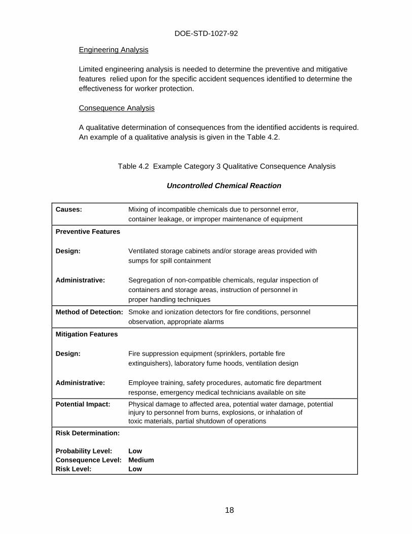
Consequence Analysis
A qualitative determination of consequences from the identified accidents is required. An example of a qualitative analysis is given in the Table 4.2.
Table 4.2 Example Category 3 Qualitative Consequence Analysis
Uncontrolled Chemical Reaction
Causes: Mixing of incompatible chemicals due to personnel error,container leakage, or improper maintenance of equipment
Preventive Features
Design: Ventilated storage cabinets and/or storage areas provided withsumps for spill containment
Administrative: Segregation of non-compatible chemicals, regular inspection of containers and storage areas, instruction of personnel inproper handling techniques
Method of Detection: Smoke and ionization detectors for fire conditions, personnelobservation, appropriate alarms
Miti gation Features
Design: Fire suppression equipment (sprinklers, portable fireextinguishers), laboratory fume hoods, ventilation design
Administrative: Employee training, safety procedures, automatic fire departmentresponse, emergency medical technicians available on site
Potential Impact: Physical damage to affected area, potential water damage, potentialinjury to personnel from burns, explosions, or inhalation oftoxic materials, partial shutdown of operations
Risk Determination:
Probabilit y Level: LowConsequence Level: MediumRisk Level: Low
DOE-STD-1027-92
19
4.1.2.b Nuclear Hazard Category 2 Facilities
DEFINITIONHazard Analysis shows the potential for significant on-site consequences.
INTERPRETATIONFacilities with the potential for nuclear criticality events or with sufficient quantitiesof hazardous material and energy which would require on-site emergency planningactivities (see Attachment 1).
This category of facilities contains Category B reactors and the most significantnonreactor nuclear facilities within the DOE complex. While these facilities aredifferent in design, construction, and operation, the non-reactor facilities are similarin character to chemical industrial facilities. Extensive work has been performed inthe development of analysis techniques for such facilities. Many of thesetechniques are documented in several American Institute of Chemical Engineers(AIChE)-sponsored reports and are described in the Occupational Safety andHealth Administration (OSSA) Regulation, 29 CFR 1910.119, Process SafetyManagement. Because these techniques are driven by the overall complexity ofthe facility operations, judgment is needed on the type and level of analysisrequired to obtain sufficient information on the safety of the facility in order tojudge its overall acceptability.
The facilities in this category represent a level of hazard for which significantmanagement attention is warranted and thus require on-site emergency planning.
Release Mechanisms
There are many analytical techniques available for evaluating the safety of thewide spectrum of chemical and nuclear DOE facilities of varying complexity. These techniques are commonly applied in the design and operation of varioustypes of processes in many industries. A good reference for applying thesetechniques is "Selecting Hazard Evaluation Techniques of Guidelines for HazardEvaluation Procedures," Second Edition with Worked Examples (Center forChemical Process Safety, 1992). A list of target levels of analysis sophisticationfor types of operations in order of increasing complexity is presented below:
1) Low-Complexity Operations
Use Hazard Analysis
Low-complexity operations include those in which very little or noprocessing of materials takes place. Waste storage, vaults, tanks,cylinders, canisters, or even very simple batch laboratories are examples ofsuch facilities. Release mechanisms are largely intuitive or straightforwardand can generally be identified by simple checklists. Hazard Analysis that
DOE-STD-1027-92
20
has already been performed (see Section 4.1.1) is considered sufficient foridentifying release mechanisms.
2) Single-Failure Electro-Mechanical Systems
Use Failure Modes and Effects Analysis (FMEA)
These systems include relatively simple electrical and mechanical devicesin which a single-failure mechanism causes a release of materials. Simpleone-step processes, single glove box operations, and small furnaces areexample of such devices. FMEA is a bottom-up approach that looks at thefailure of each element of a system or process and identifies theconsequence of each failure. FMEA is most appropriate for analysis ofsmall segments of a system or process when it is determined that failure ofsingle components in this segment could lead to system or process failureor release of material.
FMEA has some limitations which must be recognized to ensure itsappropriate use. First, FMEA is not very efficient for large-scale systemsanalysis because, by virtue of its bottom-up approach, it examines anddocuments the effects of component failures having little, if any, relevanceto system failure or potential release. Second, FMEA considers only onefailure at a time and has no logical process for considering multiple orcombined failures. Third, FMEA is strictly equipment-oriented. It looks atfailure of equipment in different nodes and assesses their consequencesbut does not look at failures of a process, which, by its very nature, mayhave complexities and instabilities far beyond those which can be assessedonly by examining the failure of individual components.
3) Systems with Redundant Barriers or Requiring Multiple Failures
Use Event Tree Analysis (ET)
ET analysis is a simple approach to delineating sequences of events whichcould lead to an undesired event. An undesired event could be uncontrolledrelease of hazardous material from a facility or core damage in a reactor. Inthe ET analysis, for each initiating event, various systems or barriers designedto prevent the occurrence of the undesired event or to mitigate the progress ofthe accident are identified. At each node, the success or failure of thesesystems or barriers, known as event tree headings, is graphically shown. The result is a pictorial representation of various combinations of systems orbarriers which succeed or fail to prevent the occurrence of the undesiredevent or to achieve a final safe condition. ET analysis is most helpful fordelineation of sequences of events leading to release of material when thereare multiple or redundant barriers for mitigation of the progression of theaccident. Examples of such sequences include fire scenarios or seismic
DOE-STD-1027-92
21
events. In such cases, the combination of various barrier successes andfailures is best represented by using ET analysis.
4) Large, Moderately Complex Processes
Use Fault Tree Analysis (FT)
Large, moderately complex processes include solid handling (e.g.,machining and assembly) activities which include rather simple movementof materials from one discrete step to another. Both ET analysis and FTanalysis techniques are appropriate for such facilities. FT analysis is a top-down approach for systematic assessment of various ways by which anundesirable event can occur. It begins with the undesirable event andproceeds to identify the event or sequence of events leading to that event. The fault tree can be developed to any desired level of detail. Ifquantification is desired, the fault tree is usually developed to the lowestlevel where data for these basic events are available, be it the subsystem,component, or component piece or part level.
Since FT analysis starts from the undesirable event and logically identifiesbasic fault conditions which can contribute to its occurrence, only thosefaults contributing to the occurrence of undesired event are modeled. Thisprocess is much more efficient than bottom-up approaches such as FMEAand is the main reason for its wide spread use. FT analysis is most suitablefor analysis of large, moderately complex systems or processes wheremultiple component failures including human errors can contribute to thefailure of the system or process.
5) Complex Fluid Processes
Use Hazard and Operability Studies (HAZOP)
Complex fluid processes involve arrays of piping, tanks, and instrumentationand control systems. Examples of these processes include PUREX,chemical separations, isotope separations (e.g., uranium enrichment), andpetrochemical processing. HAZOP is a standard and widespread techniqueused for the analysis of chemical flow processes. The main elements ofHAZOP include determining (1) the hazards which exist in a unit or areassociated with a process, (2) the effects associated with the hazard (e.g.,safety, environmental, economic), (3) the occurrence of accidents, and (4)the measures to prevent a hazard from occurring or to mitigate the effects ofan accident or failure.
HAZOP entails the investigation of deviations from design intent for aprocess by a team of individuals with expertise in different areas such asengineering, chemistry, safety, operations, and maintenance. The approach
DOE-STD-1027-92
22
is to review the process in a series of meetings during which themultidisciplinary team “brainstorms” the plant design methodically byfollowing a sequence based on prescribed guide words and the teamleader’s experience. The guide words are used to ensure that the design isexplored in every conceivable way. The HAZOP is based on the principlethat several experts with different backgrounds can interact and betteridentify problems when working together than when working separately andcombining their results.
Generally, HAZOP should be used for identifying accident scenariosassociated with continuous processing which involves the control of asignificant number of parameters in order to maintain the process in steady-state conditions and within safe limits. Such processes generally havesystems intended to monitor key parameters. Such monitoring systems mayinterface with automatic control and protection systems which act to maintainthe process in a safe condition or may only trigger alarms to alert theoperator that a parameter change requires a response. Thus, such aprocess can be either one that is automatically controlled and generallyexpected to operate without or with a minimum of supervision, or onerequiring intense operator involvement for control. For this reason, detaileddesign information (e.g., Piping & Instrumentation Diagrams) is required forthe analysis.
Fault trees may be used to complement to the HAZOP process. However,the use of fault trees in this context does not imply that the trees should bequantified probabilistically since the purpose is only the identification ofscenarios for release.
6) High Complexity Facilities
Use Integrated Event Tree and Fault Tree Techniques (ETs/FTs)
Facilities with a large number of interdependent components or systems andfluid flow processes are highly complex. Highly interdependent systems andcomponents should not be taken to include basic buildings systems such asHeating, Ventilation, and Air Conditioning (HVAC) and electrical powerdistribution systems unless these systems have significant effect on theprogress of the accident sequence. Highly complex facilities includemulti-component transfer and control systems for which extensiveinstrumentation and control systems are needed. Extensive redundancy atthe component, system, and safety level are also inherent in highly complexfacilities. Such processes generally cannot be completely controlled throughmanual actions because the interactions between systems are too intricatefor an operator to interpret in the time required for action. Thus, theseprocesses are generally characterized by large-scale monitoring andautomatic control systems. Further, such facilities generally vary greatly in
DOE-STD-1027-92
23
the design of the plant systems, especially safety systems. Large powerreactors and very large chemical processing or petroleum refineries arerepresentative of this class of facilities.
For such facilities, the extensive use of event trees and fault trees is neededto understand the potential release mechanisms. The specification of theuse of these techniques is due to the complex system interdependenciesfound in such facilities. ET/FT is capable of clarifying theseinterdependencies. The ET/FT technique involves defining initiating eventsleading to process disturbance and constructing detailed ET and FT modelsto represent plant response to various accident conditions resulting fromthose disturbances. These techniques have been proven to be especiallyuseful in evaluating processes involving very complex systems with highlevels of integration and interdependency.
Connecting of the initiating event and ET and FT models in a structuredfashion is a proven technique capable of handling, in an efficient andcomprehensive fashion, the very complex nature of the system designs,interactions, and dependencies prevalent in these processes. A large part ofthe reason for selecting this technique is that the nature of the hazard isstraightforward, but its possible causes are numerous. For example,insufficient cooling to the reactor core leads to the release of large quantitiesof radionuclides from the core, but the causes of loss of coolant are manyand intricate. Thus, the emphasis on systems is a key benefit for evaluatingthese processes; other techniques structured to consider the hazardsthemselves (such as HAZOP) are not required.
Further, because the integrated nature of the processes results in a largenumber of intricate combinations of failures which can lead to a release, theprobabilistic approach used is essential in determining which of thesecombinations is necessary to consider in addressing consequences, for thesheer number of them makes the use of engineering judgment morecomplicated and less reliable.
Sequence Selection
As general guidance for Category 2 facilities, it is necessary to include a range ofaccident conditions to adequately characterize the safety basis for the facility. Accident sequences should be selected to provide insight into the hazardsassociated with the facility. Because these accidents are used in establishing theTechnical Safety Requirements for the facility, their selection is very important. The selection process should be based on the implementation of the analysistechniques discussed in the previous section. The search should include higher-probability unique events which pose hazards only to workers as well as unusual,lower-probability events which include a reasonable maximum release from thefacility. Design basis natural phenomena should also be included in the range of
DOE-STD-1027-92
24
undesired events. The following section discusses the range of events insomewhat more detail.
1) Operational Accidents - Operational accidents are those that result fromprocesses and activities involved in operating the facility and generallycover many diverse routine or non-routine events with potentially adverseconsequences to the workers or the public. Fires, explosions, spills,process disturbances, and criticality events are included as operationalevents. A reasonable set of operational events should be selected whichrepresents the accident release mechanisms identified. Explicitconsideration should be given to non-routine or unique events whichpresent significant risks to facility workers. These events should includeprocess explosions or criticalities which have the potential for seriousworker injury or death but would not necessarily cause significant releasesoutside of the facility.
2) Design Basis Natural Phenomena Events - As currently defined by DOE,design basis natural phenomena events include earthquakes, high winds,tornados, floods, etc. for which the facility has been (or should have been)designed. Explicit consideration should be given to such sequences and arepresentative set of accidents described.
3) External Events - The effect of facility- or site-specific events such asairplane crashes, transportation accidents, or collocated facility accidents onthe Category 2 facility should also be addressed.
Sequence Engineering Analysis
Engineering analysis concentrates on those structures, systems, and componentsrelevant to the accident scenarios developed. Although listed before actualconsequence determination, it will normally be conducted in an integrated fashionwith accident quantification. Engineering analysis is needed to determine theamount of material which would be released in the scenario. For example, if anaccident scenario assumes that the High Efficiency Particulate Air (HEPA) filterswill work as designed, then an engineering analysis is needed to ensure that theaccident conditions experienced by the filters is within the filter design envelope. However, for an event such as the explosion of an ion exchange column, wherethere is sufficient energy to lift the charging lid on a dissolver, an elaborateanalysis of the structural strength of the vessel and its lid would be unwarranted ifthe consequences are insignificant.
It should be noted that the detailed engineering analysis could be part of thedesign documentation for the facility. Also, the engineering analysis will become asignificant part of the designation of safety class systems, structures, andcomponents and drive the Technical Safety Requirements for the facility.

DOE-STD-1027-92
25
Consequence Analysis
Consequence analysis is the final step in the accident analysis section of the SAR. For Category 2 facilities, the following analyses must be provided.
1) Source Term Analysis - Provide a reasonably conservative analysis by usingdefensible realistic values of the characteristics of the release from thebuilding. This analysis includes the amount and form of material, the timingof the release, energy, particle size distribution, etc.
2) Dose Assessment - Perform dose calculations by using conservative analysistechniques for workers and site boundary distances.
4.1.2.c Nuclear Hazard Category 1 Facilities
DEFINITIONHazard Analysis shows the potential for significant off-site consequences.
INTERPRETATIONCategory A reactors and facilities designated by the PSO.
Release Mechanisms
Refer to the discussion in Category 2 for release mechanism analysis techniques. It should be noted that large reactors would probably be considered highlycomplex facilities and utilize fully, integrated, quantitative ET and FT techniques.
Sequence Selection
For highly complex facilities, an extensive set of accident sequences need to becategorized so that a reasonable spectrum of sequences is analyzed.
Engineering Analysis
Extensive engineering analysis is required for Category 1 facilities.
Consequence Analysis
The requirements are the same as the ones given for Category 2 facilities.

DOE-STD-1027-92
26
INTENTIONALLY BLANK

DOE-STD-1027-92ATTACHMENT 1
A - 1
HAZARD CATEGORIZATION OF DOE FACILITIES
The hazard categorization approach and criteria outlined below can be consistently appliedto all DOE nuclear facilities. It is based on a simple approach which is intended to meetDOE Order 5480.23 requirements for a preliminary assessment and hazard categorization. This approach is also intended to supplement the graded approach as discussed inSection 4 of the guidance document. An interpretation of the Hazard Categories discussedin the Order with detailed groundrules for each category, is given below.
General Groundrules
Facilit y Segmentation
In facility categorization, flexibility must be allowed in the definition of facility segments. Many DOE facilities conduct a wide variety of activities in one facility, ranging from simpleassay or lab experiments to complex fluid flow separations. It is necessary to avoid placingexcessive requirements on simple or even trivial co-located operations. The concept ofindependent facility segments should be applied where facility features preclude bringingmaterial together or causing harmful interaction from a common severe phenomenon.
It should be noted that DOE 5480.23 states that an analysis and categorization is to beperformed on “processes, operations, or activities” and not necessarily whole facilities. Forthe purposes of hazard categorization and estimating hazardous material inventory, theobjective is to understand the available hazards that could interact and cause harm toindividuals or the environment. It is not desirable to estimate the potential consequencesfrom an inventory of hazardous materials when facility features would preclude bringing thismaterial together. Therefore, the standard permits the concept of facility segmentationprovided the hazardous material in one segment could not interact with hazardous materialsin other segments. For example, independence of HVAC and piping must exist in order todemonstrate independence for facility segmentation purposes. This independence must bedemonstrated and places the “burden of proof” on the analyst.
Treatment of Sealed Sources, Commerciall y Available Products and DOT Shippin gContainers
Sealed radioactive sources that are engineered to pass the special form testing specified bythe Department of Transportation (DOT) in 49 CFR 173.469 or testing specified by ANSIN43.6 “Sealed Radioactive Sources, Categorization,” may be excluded from summation of afacility’s radioactive inventory. The facility must have documentation that the source orprototypes of the source have been tested and passed the tests specified by DOT or ANSI. Facilities must also have in place a source control policy that complies with DOE Notice5400.9, “Sealed Source Control Policy” and the source control policy specified in Article 431of the DOE RadCon Manual. Should a sealed radioactive source fail, as indicated by anincrease in the removable activity, the source shall be removed from service and handled inaccordance with the source control policy established for the facility.

DOE-STD-1027-92ATTACHMENT 1
A - 2
Hazardous materials used in exempted, commercially available products, should not beconsidered part of a facility’s inventory. These materials are described in 10 CFR 30 Parts30.11–30.19 and include timepieces, illumination devices, thermostats, electron tubes,microwave receiver tubes, etc.
Additionally, material contained in DOT Type B shipping containers (with or withoutoverpack) may also be excluded from summation of a facility’s radioactive inventory if theCertificates of Compliance are kept current and the materials stored are authorized by theCertificate. However, Type B containers without overpack should have heat protectionprovided by the facility’s fire suppression system.
These exclusions do not apply to fissile material in the determination of Hazard Category 2status relative to criticality.
Summation of Radionuclide Threshold Ratios
Facilities or facility segments where there are combinations of radioactive materials shouldbe designated as Category 2 or 3 if the sum of the ratios of the quantity of each material tothe Category 2 or 3 thresholds exceeds one (e.g., [inventory of isotope A/threshold ofisotope A] + [inventory of isotope B/threshold of isotope B] + [inventory of isotopen/threshold of isotope n] >1).
Part Time Inventor y
A facility that is involved with an inventory of hazardous materials that varies with time mustbe categorized on the basis of its maximum inventory of hazardous materials.
Hazard Categories
Hazard Cate gory 1
DEFINITION: Hazard Analysis shows the potential for significant off-siteconsequences.
INTERPRETATION: Category A reactors and facilities designated by PSO.
CONSIDERATIONS: Category A reactors are those that have a steady-state power levelgreater than 20 MWt.
Hazard Cate gory 2
DEFINITION: Hazard Analysis shows the potential for significant on-siteconsequences.
DOE-STD-1027-92ATTACHMENT 1
A - 3
INTERPRETATION: Facilities with the potential for nuclear criticality events or withsufficient quantities of hazardous material and energy, which wouldrequire on-site emergency planning activities.
RADIOLOGICALCRITERIA: The criterion is that given in 10 CFR 30, with rebaselined calculation.
This criterion is essentially possession of quantities of material whoseunmitigated release could produce total doses of 1 rem in the rangeof 100 meters from the facility.
In addition, any facility containing fissile material in quantities greaterthan the theoretical minimum mass limits for criticality emergenciesas specified in ANSI/ANS-8.1-1983, R88 "Nuclear Criticality Safety inOperations with Fissionable Materials Outside Reactors" should beincluded. For aqueous solutions of U , U , and Pu these values233 235 239,
are 500, 700, and 450 grams, respectively. Credit may be taken ifsegmentation or nature of process precludes potential for criticality.
CONSIDERATIONS: The intent of this threshold is to capture those quantities of materialwhose unmitigated release would require an emergency plan for on-site evacuation. The NRC has specified certain values in 10 CFR 30with a defined threshold of a 1 rem dose at 100 meters. DOE hasevaluated these numbers and made certain modifications to releasefractions which are explicitly allowed in the regulation. DOE has alsomodified the meteorology used in the threshold calculation.
Specific groundrules for Category 2 hazard categorization are as follows:
1. In general, it is necessary to consult the individual threshold valuesonly if an individual isotope is being isolated and collected for somepurpose. For example, if a facility processes weapons gradeplutonium, it can simply be classified on the aggregate amount ofPu present without specifying quantities of trace isotopes (i.e.,239
Pu , Pu , Am , etc.) carried along in the mixture. Likewise, if a238 240 241
fuel reprocessing plant has more than 1000 curies of mixed fissionproducts, it is a Category 2 facility with no need to consider individualradionuclide make-up.
2. Facilities are considered Category 2 if the potential for criticality existsin the storage arrays and processing means used.
Hazard Cate gory 3
DEFINITION: Hazard Analysis shows the potential for significant but localizedconsequences.

DOE-STD-1027-92ATTACHMENT 1
A - 4
INTERPRETATION: Facilities with quantities of hazardous radioactive materials, whichmeet or exceed the Table A.1 values.
RADIOLOGICAL CRITERIA: Quantities of radioactive materials as specified in Table A.1.
CONSIDERATIONS: The definition of the Category 3 threshold is designed to excludethose facilities which cannot have a significant radiological impactoutside the facility.
DISCUSSION
Hazard Cate gory 1
DOE Order 5480.23 states that Category 1 hazards have the potential for “significant off-site consequences.” Based on total curie content, potential material forms, and maximumenergy for dispersion available, one class of facilities which possess this hazard potential isthe Class A nuclear reactors. In addition, the PSO may designate other facilities asCategory 1 if he feels there exists the potential for significant off-site consequences.
Hazard Cate gory 2
The approach for designating Category 2 hazards was constructed from existing regulationswhich define minimum thresholds for many radionuclides and hazardous chemicals on thebasis of consequences from these hazards in the immediate vicinity of a facility. Table A.1provides the resulting TQs for radioactive materials which define a Category 2 facility. Such an approach is consistent with the intent of DOE Order 5480.23 to categorize at level2 those facilities with the potential for “significant on-site consequences.”
For radioactive materials, 10 CFR 30 derived quantities above which byproduct materiallicensees must provide emergency plans for responding to a release because such arelease could give a dose of 1 rem at 100 meters under very conservative meteorologicalconditions (stable air with intermittent breezes, i.e., F at 1 m/sec). Table A.1 includesthresholds for byproduct material on the basis of this regulatory premise. Differencesbetween the NRC calculation and the DOE calculation are explained in the Calculations andAssumptions Section of this Attachment.
The threshold value for fissile material as specified in Table A.1 is the minimum theoreticalmass necessary for a nuclear criticality to occur with moderation and reflection. Thesevalues for aqueous solutions are approximately 450 grams for Pu , 500 grams for U ,239 233
and 700 grams for U . This stipulation is necessary because the on-site effects of a235
criticality are potentially severe within the immediate vicinity of a facility. Category B nuclearreactors should therefore be classified as Category 2 since critical quantities of fissile
DOE-STD-1027-92ATTACHMENT 1
A - 5
materials are present in these facilities but not in sufficient quantities to represent asignificant off-site impact.
Hazard Cate gory 3
Category 3 is designed to capture facilities which largely include lab operations, low levelwaste handling facilities, and research machines which possess less than the Category 2quantities of material and are considered to represent a low hazard. DOE Order 5480.23states that facilities should be classified as Level 3 if there is only the potential for"significant localized consequences." Essentially all industrial facilities have a potential forsignificant localized consequences because the potential to injure workers from typicalindustrial accidents is always present. However, Category 3 facilities pose additionalhazards due to the presence of radionuclides. To establish a system based on inventories,DOE has modified the EPA definitions of RQs for radionuclides contained in 40 CFR 302.4,Appendix B. The values for radionuclides represent levels of material which, if released,would produce less than 10 rem doses at 30 meters based on 24 hour exposure. Table A.1provides the Category 3 thresholds for radionuclides.
Results
Categorization of most nuclear hazards present in facilities or facility segments should bepossible from the thresholds listed in Table A.1. Further discussion on the origin of somethresholds is provided in the following section on “Calculations and Assumptions.”
CALCULATIONS AND ASSUMPTIONS
Calculation of Category 2 Radiological Thresholds
The NRC derived 10 CFR 30, Schedule C threshold quantities which could result in a doseof 1 rem at 100 meters by using standard air dispersion/dose calculations. The basiccalculation stated is as follows:
Q = (1 rem)/(RF*(H + H + H ))I G CS
whereQ = Quantity of material used as threshold (grams)
RF = Release fraction for material of concern (unitless)
H = Effective dose equivalent from inhalation (rem/gm)I
H = Effective dose equivalent from ground contamination (rem/gm) G
H = Effective dose equivalent from cloud shine (rem/gm)CS
DOE-STD-1027-92ATTACHMENT 1
A - 6
The NRC then stated that “for all materials of greatest interest for fuel cycle and otherradioactive material licensees, the dose from the inhalation pathway H will dominate theI
dose” and dismissed the other contributors. Simplifying assumptions for Gaussiandispersion and particle deposition were then used to calculate inhalation doses.
In modifying the NRC results, DOE has restated the equation above as
Q = (1 rem)/(RF*SA*X/Q*(CEDE*RR + CSDE))where
Q = Quantity of material used as threshold (grams)
RF = Airborne release fraction of material averaged over an entire facility(unitless)
SA= Specific activity of radionuclide released (Ci/gm)
X/Q= Expression accounting for dilution of release at a point under givenmeteorological conditions (sec/m ) 3
CEDE= Committed effective dose equivalent for a given radionuclide(rem/Ci)
RR= Respiration rate, which is assumed equal to the standard valueused for an active man (3.5 E-4 m /sec)3
CSDE= Cloud shine dose equivalent (rem*m /Ci*sec)3
Specific modifications to forms of the equation are discussed in distinct sections below.
Exposure Pathwa ys
As can be seen from the modified equation, DOE concurred with the NRC’s dismissal of theground contamination exposure pathway. In general, DOE concurred with the dismissal ofcloudshine exposure as well because this path accounted for, on average, slightly less than2% of dose for all radionuclides but the noble gases. Although, for the types of material thatDOE handles, it is expected that the values for noble gases will be included in the mixedfission product threshold, DOE decided to retain this exposure pathway in the calculation forcompleteness.
Meteorolo gical Conditions
DOE chose to modify the NRC meteorological assumptions used for hazard categorizationpurposes. NRC used F stability at 1 m/sec meteorological conditions whereas DOE used Dstability at 4.5 m/sec for the following reasons:
DOE-STD-1027-92ATTACHMENT 1
A - 7
1. The NRC use of a conservative value at 100 meters was based on the fact that mostof the commercial radionuclide handling facilities for which emergency planning wasbeing considered have boundaries with populated areas at or less than 100 meters. The majority of DOE Category 2 facilities have site boundary distances much greaterthan 100 meters.
2. The calculation of values at 100 meters achieves a less accurate result fromdispersion models since building wake effects are still a predominant effect at thisdistance.
3. The use of F at 1 m/sec was considered to be overly conservative, particularly inlight of the difference in application between the DOE and NRC in the resultingcalculated quantities. DOE consequently decided to use a Pasquill stability class Dat 4.5 m/sec windspeed, a value used for comparison by NRC, as the assumedmeteorological conditions for the dispersion calculations. Using a no-buoyancymodel, which will by itself be conservative for many releases, a nominal distance forthe 1 rem evaluation would be slightly less than 300 meters. These conditionscorrespond to a X/Q of approximately 1 E-4 sec/m , which is considered adequate3
for a calculation which does not account for mitigation or size distribution ofparticles.
Release Fractions
The final set of assumptions modified by DOE were the set of release fractions used by theNRC in NUREG-1140. NRC proposed the following set of release fractions based uponexperimental data and historical observations:
1. Noble Gases 1.0 2. Highly Volatile/Combustible 0.5 3. Carbon 1 E-2 4. Semi-volatile 1 E-2 5. Unknown form 1 E-2 6. Nonvolatile powder 1 E-3 7. U and Pu Metal 1 E-3 8. Nonvolatile solids 1 E-4 9. Nonvolatiles in flammable liquid 5 E-310. Nonvolatiles in non-flammable liquid 1 E-3
DOE desired to simplify this list because some components could be combined, some ofthe categories were not used by the NRC, and the regulatory framework for the list clearlyallowed lowering release fractions for regulatory calculations.
Therefore, DOE first changed the noble gas category to simply gases and moved specificgases such as tritium from the highly volatile/combustible category into the gas category,where the release fraction of 1.0 was retained. DOE then chose to keep the highly
DOE-STD-1027-92ATTACHMENT 1
A - 8
volatile/combustible category as defined by NRC, with the addition of sodium to the group. The release fraction of 0.5 is somewhat higher than is usually estimated for thesecompounds, but DOE chose to retain the conservative value. At the same time, DOE alsonoted that use of such a release fraction would not be appropriate if a flammablesubstance such as phosphorus had been turned into a phosphoric acid solution, thenormal form for research activities. At that point, it would be a material best representedby the general powder/liquid/solid category described below.
DOE did not consider carbon-14 thresholds to be a major issue on the basis of typicalquantities used. As a result, carbon was grouped as a semi-volatile with the same releasefraction of 1 E-2. The DOE then decided to abandon the use of the unknown formcategory as an unnecessary complication. NRC used this value for a number of theisotope thresholds, largely relating to materials unlikely to be found outside of fissionproduct mixtures or sources. The use of a curie threshold for fission product mixtureswould capture such material in most DOE applications. Additionally, there was nocompelling reason to believe these materials would react to physical energy stressesdifferently from most powders, liquids, or solids.
NRC did not use the nonvolatile in flammable liquid, nonvolatile in non-flammable liquid, ornonvolatile solid categories in final calculations. DOE concurred with this approach anddropped these categories because applying average release fractions over an entirebuilding makes such detailed subdivision of questionable value. DOE believes that the 1E-3 value is a reasonably conservative approximation because it will be applied to anentire building without scenario-specific considerations. DOE recognizes that someaccidents, particularly those involving powders and liquids, can produce much highervalues, whereas metal incidents would normally produce slightly smaller release fractions. However, it is unlikely that any event will affect all material in a building, and high releasephenomena such as ion exchange explosions, powder pressurization, etc., will affect onlya localized fraction of the material. Therefore, the value is believed an adequate averagefor hazard categorization purposes.
The final release fraction values for Hazard Category 2 were produced by DOE as listedbelow:
1. Gases 1.0(such as tritium, krypton, xenon, argon, radon,chlorine, etc.)
2. Highly volatile/combustible 0.5(phosphorus, sulfur, potassium, iodine,sodium, bromine)
3. Semi-volatile 1 E-2(selenium, mercury, cesium, polonium,tellurium, ruthenium, carbon)
DOE-STD-1027-92ATTACHMENT 1
A - 9
4. Solid/Powder/Liquid 1 E-3(All materials not listed above)
Calculation of Category 3 Radiological Thresholds
In the Senior Nuclear Managers’ meeting of October 26, 1992, DOE determined that it isreasonable to set the limit based upon the value that is accepted by the EPA for protectionof workers for planned reentry into a facility after an incident (EPA in Manual of ProtectiveAction Guides and Protective Actions for Nuclear Incidents, EPA 400-R-92-001) and citedin Appendix 2A of the RadCon Manual, which is 10 rem.
DOE has chosen to use an EPA model* to calculate the threshold quantities for Category3. The model assumes that: the distance from the point of release to the point ofexposure is 30 meters; the dose-equivalent limit is 10 rem effective whole body dose; andthere is no radioactive decay (for the sake of conservatism and simplicity). For the periodof exposure, the models used assume that persons are exposed for one day for inhalationand direct exposure, but that persons are exposed for longer periods through theingestion pathway.
See Section 3.0 of this Standard for guidance on the proper use of this Table.
* 40 CFR 302.4 Appendix B, calculations described in User’s Manual for theRadionuclides Database Version 1.02
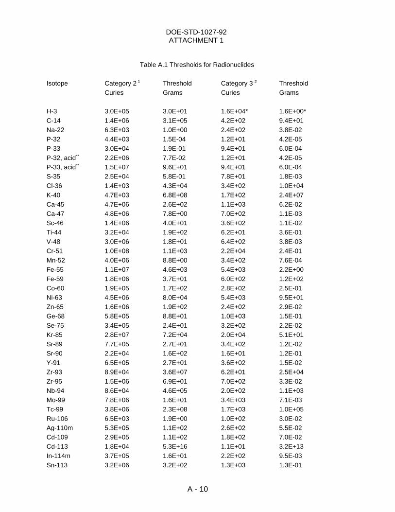
DOE-STD-1027-92ATTACHMENT 1
A - 10
Table A.1 Thresholds for Radionuclides
Isotope Category 2 Threshold Category 3 Threshold 1 2
Curies Grams Curies Grams
H-3 3.0E+05 3.0E+01 1.6E+04* 1.6E+00*C-14 1.4E+06 3.1E+05 4.2E+02 9.4E+01Na-22 6.3E+03 1.0E+00 2.4E+02 3.8E-02P-32 4.4E+03 1.5E-04 1.2E+01 4.2E-05P-33 3.0E+04 1.9E-01 9.4E+01 6.0E-04P-32, acid 2.2E+06 7.7E-02 1.2E+01 4.2E-05**
P-33, acid 1.5E+07 9.6E+01 9.4E+01 6.0E-04**
S-35 2.5E+04 5.8E-01 7.8E+01 1.8E-03Cl-36 1.4E+03 4.3E+04 3.4E+02 1.0E+04K-40 4.7E+03 6.8E+08 1.7E+02 2.4E+07Ca-45 4.7E+06 2.6E+02 1.1E+03 6.2E-02Ca-47 4.8E+06 7.8E+00 7.0E+02 1.1E-03Sc-46 1.4E+06 4.0E+01 3.6E+02 1.1E-02Ti-44 3.2E+04 1.9E+02 6.2E+01 3.6E-01V-48 3.0E+06 1.8E+01 6.4E+02 3.8E-03Cr-51 1.0E+08 1.1E+03 2.2E+04 2.4E-01Mn-52 4.0E+06 8.8E+00 3.4E+02 7.6E-04Fe-55 1.1E+07 4.6E+03 5.4E+03 2.2E+00Fe-59 1.8E+06 3.7E+01 6.0E+02 1.2E+02Co-60 1.9E+05 1.7E+02 2.8E+02 2.5E-01Ni-63 4.5E+06 8.0E+04 5.4E+03 9.5E+01Zn-65 1.6E+06 1.9E+02 2.4E+02 2.9E-02Ge-68 5.8E+05 8.8E+01 1.0E+03 1.5E-01Se-75 3.4E+05 2.4E+01 3.2E+02 2.2E-02Kr-85 2.8E+07 7.2E+04 2.0E+04 5.1E+01Sr-89 7.7E+05 2.7E+01 3.4E+02 1.2E-02Sr-90 2.2E+04 1.6E+02 1.6E+01 1.2E-01Y-91 6.5E+05 2.7E+01 3.6E+02 1.5E-02Zr-93 8.9E+04 3.6E+07 6.2E+01 2.5E+04Zr-95 1.5E+06 6.9E+01 7.0E+02 3.3E-02Nb-94 8.6E+04 4.6E+05 2.0E+02 1.1E+03Mo-99 7.8E+06 1.6E+01 3.4E+03 7.1E-03Tc-99 3.8E+06 2.3E+08 1.7E+03 1.0E+05Ru-106 6.5E+03 1.9E+00 1.0E+02 3.0E-02Ag-110m 5.3E+05 1.1E+02 2.6E+02 5.5E-02Cd-109 2.9E+05 1.1E+02 1.8E+02 7.0E-02Cd-113 1.8E+04 5.3E+16 1.1E+01 3.2E+13In-114m 3.7E+05 1.6E+01 2.2E+02 9.5E-03Sn-113 3.2E+06 3.2E+02 1.3E+03 1.3E-01
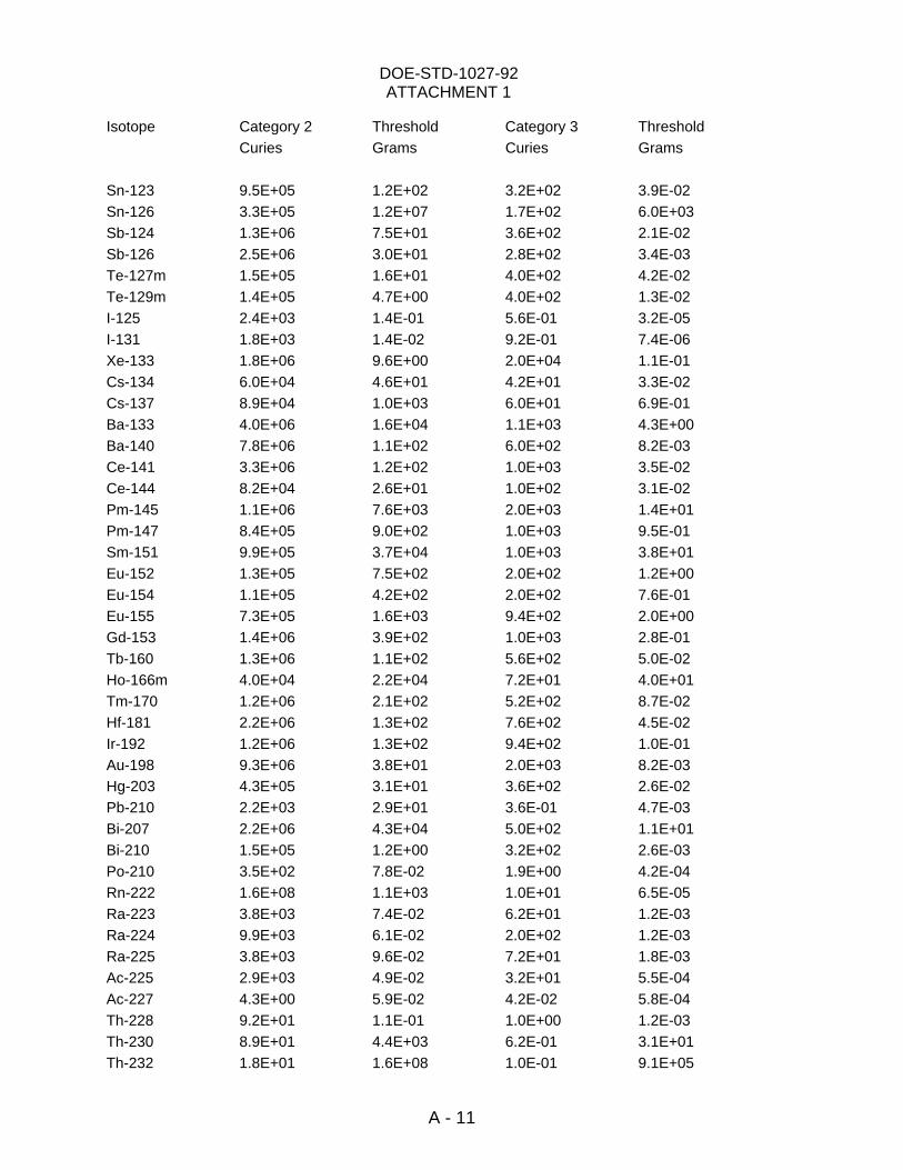
DOE-STD-1027-92ATTACHMENT 1
A - 11
Isotope Category 2 Threshold Category 3 ThresholdCuries Grams Curies Grams
Sn-123 9.5E+05 1.2E+02 3.2E+02 3.9E-02Sn-126 3.3E+05 1.2E+07 1.7E+02 6.0E+03Sb-124 1.3E+06 7.5E+01 3.6E+02 2.1E-02Sb-126 2.5E+06 3.0E+01 2.8E+02 3.4E-03Te-127m 1.5E+05 1.6E+01 4.0E+02 4.2E-02Te-129m 1.4E+05 4.7E+00 4.0E+02 1.3E-02I-125 2.4E+03 1.4E-01 5.6E-01 3.2E-05I-131 1.8E+03 1.4E-02 9.2E-01 7.4E-06Xe-133 1.8E+06 9.6E+00 2.0E+04 1.1E-01Cs-134 6.0E+04 4.6E+01 4.2E+01 3.3E-02Cs-137 8.9E+04 1.0E+03 6.0E+01 6.9E-01Ba-133 4.0E+06 1.6E+04 1.1E+03 4.3E+00Ba-140 7.8E+06 1.1E+02 6.0E+02 8.2E-03Ce-141 3.3E+06 1.2E+02 1.0E+03 3.5E-02Ce-144 8.2E+04 2.6E+01 1.0E+02 3.1E-02Pm-145 1.1E+06 7.6E+03 2.0E+03 1.4E+01Pm-147 8.4E+05 9.0E+02 1.0E+03 9.5E-01Sm-151 9.9E+05 3.7E+04 1.0E+03 3.8E+01Eu-152 1.3E+05 7.5E+02 2.0E+02 1.2E+00Eu-154 1.1E+05 4.2E+02 2.0E+02 7.6E-01Eu-155 7.3E+05 1.6E+03 9.4E+02 2.0E+00Gd-153 1.4E+06 3.9E+02 1.0E+03 2.8E-01Tb-160 1.3E+06 1.1E+02 5.6E+02 5.0E-02Ho-166m 4.0E+04 2.2E+04 7.2E+01 4.0E+01Tm-170 1.2E+06 2.1E+02 5.2E+02 8.7E-02Hf-181 2.2E+06 1.3E+02 7.6E+02 4.5E-02Ir-192 1.2E+06 1.3E+02 9.4E+02 1.0E-01Au-198 9.3E+06 3.8E+01 2.0E+03 8.2E-03Hg-203 4.3E+05 3.1E+01 3.6E+02 2.6E-02Pb-210 2.2E+03 2.9E+01 3.6E-01 4.7E-03Bi-207 2.2E+06 4.3E+04 5.0E+02 1.1E+01Bi-210 1.5E+05 1.2E+00 3.2E+02 2.6E-03Po-210 3.5E+02 7.8E-02 1.9E+00 4.2E-04Rn-222 1.6E+08 1.1E+03 1.0E+01 6.5E-05Ra-223 3.8E+03 7.4E-02 6.2E+01 1.2E-03Ra-224 9.9E+03 6.1E-02 2.0E+02 1.2E-03Ra-225 3.8E+03 9.6E-02 7.2E+01 1.8E-03Ac-225 2.9E+03 4.9E-02 3.2E+01 5.5E-04Ac-227 4.3E+00 5.9E-02 4.2E-02 5.8E-04Th-228 9.2E+01 1.1E-01 1.0E+00 1.2E-03Th-230 8.9E+01 4.4E+03 6.2E-01 3.1E+01Th-232 1.8E+01 1.6E+08 1.0E-01 9.1E+05
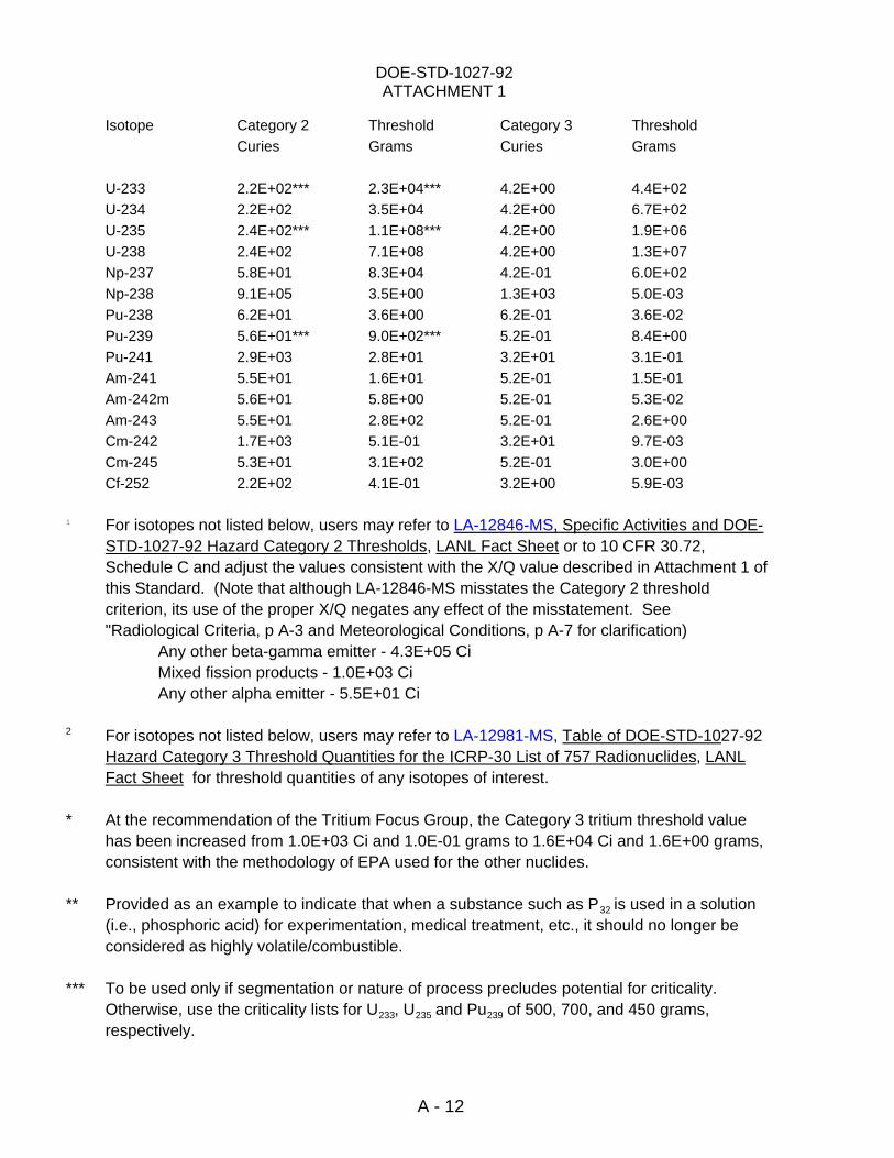
DOE-STD-1027-92ATTACHMENT 1
A - 12
Isotope Category 2 Threshold Category 3 ThresholdCuries Grams Curies Grams
U-233 2.2E+02*** 2.3E+04*** 4.2E+00 4.4E+02U-234 2.2E+02 3.5E+04 4.2E+00 6.7E+02U-235 2.4E+02*** 1.1E+08*** 4.2E+00 1.9E+06U-238 2.4E+02 7.1E+08 4.2E+00 1.3E+07Np-237 5.8E+01 8.3E+04 4.2E-01 6.0E+02Np-238 9.1E+05 3.5E+00 1.3E+03 5.0E-03Pu-238 6.2E+01 3.6E+00 6.2E-01 3.6E-02Pu-239 5.6E+01*** 9.0E+02*** 5.2E-01 8.4E+00Pu-241 2.9E+03 2.8E+01 3.2E+01 3.1E-01Am-241 5.5E+01 1.6E+01 5.2E-01 1.5E-01Am-242m 5.6E+01 5.8E+00 5.2E-01 5.3E-02Am-243 5.5E+01 2.8E+02 5.2E-01 2.6E+00Cm-242 1.7E+03 5.1E-01 3.2E+01 9.7E-03Cm-245 5.3E+01 3.1E+02 5.2E-01 3.0E+00Cf-252 2.2E+02 4.1E-01 3.2E+00 5.9E-03
For isotopes not listed below, users may refer to LA-12846-MS, Specific Activities and DOE-1
STD-1027-92 Hazard Category 2 Thresholds, LANL Fact Sheet or to 10 CFR 30.72,Schedule C and adjust the values consistent with the X/Q value described in Attachment 1 ofthis Standard. (Note that although LA-12846-MS misstates the Category 2 threshold criterion, its use of the proper X/Q negates any effect of the misstatement. See"Radiological Criteria, p A-3 and Meteorological Conditions, p A-7 for clarification)
Any other beta-gamma emitter - 4.3E+05 CiMixed fission products - 1.0E+03 CiAny other alpha emitter - 5.5E+01 Ci
For isotopes not listed below, users may refer to LA-12981-MS, Table of DOE-STD-1027-922
Hazard Category 3 Threshold Quantities for the ICRP-30 List of 757 Radionuclides, LANLFact Sheet for threshold quantities of any isotopes of interest.
* At the recommendation of the Tritium Focus Group, the Category 3 tritium threshold valuehas been increased from 1.0E+03 Ci and 1.0E-01 grams to 1.6E+04 Ci and 1.6E+00 grams,consistent with the methodology of EPA used for the other nuclides.
** Provided as an example to indicate that when a substance such as P is used in a solution32
(i.e., phosphoric acid) for experimentation, medical treatment, etc., it should no longer beconsidered as highly volatile/combustible.
*** To be used only if segmentation or nature of process precludes potential for criticality. Otherwise, use the criticality lists for U , U and Pu of 500, 700, and 450 grams,233 235 239
respectively.
DOE-STD-1027-92
CONCLUDING MATERIAL
Review Activities: Preparin g Activit y:
DOE EH-31DPEHEMERNE Project Number:NPNS SAFT-0004RW