document title specification of ecu configuration
TRANSCRIPT

Specification of ECU ConfigurationV2.5.0
R3.2 Rev 3
Document Title Specification of ECUConfiguration
Document Owner AUTOSAR
Document Responsibility AUTOSAR
Document Identification No 087
Document Classification Standard
Document Version 2.5.0
Document Status Final
Part of Release 3.2
Revision 3
Document Change HistoryDate Version Changed by Description
28.02.2014 2.5.0AUTOSARReleaseManagement
• Improved description aboutHandleIds• improved CDD module
configuration and made itPostBuild configurable• Miscellaneous fixes and
improvements in the document
15.05.2013 2.4.1 AUTOSARAdministration
• Support unidirectional CDDcommunication• Improved description about
HandleIds• Added post build support for CDD
25.05.2012 2.4.0 AUTOSARAdministration
• Reworked CDD configuration toreflect the direction of thecommunication• Introduced apiServicePrefix
attribute to store the CDD moduleabbreviation (changedecuc_sws_6037)
1 of 156— AUTOSAR CONFIDENTIAL —
Document ID 087: AUTOSAR_ECU_Configuration

Specification of ECU ConfigurationV2.5.0
R3.2 Rev 3
31.03.2011 2.3.0 AUTOSARAdministration
• Added section on ComplexDevice Driver (section 4.4)• Clarification of
PostBuildSelectable,PostBuildLoadable in VSMD(added ecuc_sws_6046,ecuc_sws_6047,ecuc_sws_6048,ecuc_sws_6049)• set configuration class affection
support to deprecated
14.10.2009 2.2.0 AUTOSARAdministration
Updated definition how symbolicnames are generated from the EcuC.
15.09.2008 2.1.0 AUTOSARAdministration
Fixed foreign reference toPduToFrameMapping
01.07.2008 2.0.2 AUTOSARAdministration Legal disclaimer revised.
01.02.2008 2.0.1 AUTOSARAdministration
Added reference from Container toContainerDef. Removed referencefrom Container toParamConfContainerDef.
06.12.2007 2.0.0 AUTOSARAdministration
• Changed representation of aChoiceContainerDef in an ECUConfiguration Description• Moved sections from "ECU
Configuration ParameterDefinition" into the "Specificationof ECU Configuration"(COM-Stack ConfigurationPatterns)• Updated interaction of ECU
Configuration with BSW ModuleDescription• Added specification items which
define what is allowed whencreating a Vendor SpecificModule Definition (VSMD)
2 of 156— AUTOSAR CONFIDENTIAL —
Document ID 087: AUTOSAR_ECU_Configuration

Specification of ECU ConfigurationV2.5.0
R3.2 Rev 3
• Correction of"InstanceParamRef" definition inECU Configuration Specification• Refined the available character
set of calculationFormula• Added clarification about the
usage of ADMIN-DATA to trackversion information• Document meta information
extended• Small layout adaptations made
31.01.2007 1.1.1 AUTOSARAdministration
• “Advice for users” revised• Legal disclaimer revised
06.12.2006 1.1.0 AUTOSARAdministration
• Methodology chapter revised(incl. introduction of support forAUTOSAR Services)• Added EcucElement,
EcuSwComposition,configuration class affection,LinkerSymbolDef andLinkerSymbolValue to themetamodel• Support for multiple configuration
sets added• Legal disclaimer revised
28.06.2006 1.0.1 AUTOSARAdministration Layout Adaptations
09.05.2006 1.0.0 AUTOSARAdministration Initial Release
3 of 156— AUTOSAR CONFIDENTIAL —
Document ID 087: AUTOSAR_ECU_Configuration

Specification of ECU ConfigurationV2.5.0
R3.2 Rev 3
4 of 156— AUTOSAR CONFIDENTIAL —
Document ID 087: AUTOSAR_ECU_Configuration

Specification of ECU ConfigurationV2.5.0
R3.2 Rev 3
Disclaimer
This specification and the material contained in it, as released by AUTOSAR is for thepurpose of information only. AUTOSAR and the companies that have contributed to itshall not be liable for any use of the specification.
The material contained in this specification is protected by copyright and other types ofIntellectual Property Rights. The commercial exploitation of the material contained inthis specification requires a license to such Intellectual Property Rights.
This specification may be utilized or reproduced without any modification, in any formor by any means, for informational purposes only. For any other purpose, no part ofthe specification may be utilized or reproduced, in any form or by any means, withoutpermission in writing from the publisher.
The AUTOSAR specifications have been developed for automotive applications only.They have neither been developed, nor tested for non-automotive applications.
The word AUTOSAR and the AUTOSAR logo are registered trademarks.
Advice for users
AUTOSAR Specification Documents may contain exemplary items (exemplary refer-ence models, "use cases", and/or references to exemplary technical solutions, devices,processes or software).
Any such exemplary items are contained in the Specification Documents for illustrationpurposes only, and they themselves are not part of the AUTOSAR Standard. Nei-ther their presence in such Specification Documents, nor any later documentation ofAUTOSAR conformance of products actually implementing such exemplary items, im-ply that intellectual property rights covering such exemplary items are licensed underthe same rules as applicable to the AUTOSAR Standard.
5 of 156— AUTOSAR CONFIDENTIAL —
Document ID 087: AUTOSAR_ECU_Configuration

Specification of ECU ConfigurationV2.5.0
R3.2 Rev 3
Table of Contents
1 Introduction 10
1.1 Abbreviations . . . . . . . . . . . . . . . . . . . . . . . . . . . . . . . . . 111.2 Requirements Traceability . . . . . . . . . . . . . . . . . . . . . . . . . . 11
2 ECU Configuration Methodology 15
2.1 Notation used . . . . . . . . . . . . . . . . . . . . . . . . . . . . . . . . . 152.2 Inputs to ECU Configuration . . . . . . . . . . . . . . . . . . . . . . . . . 152.3 ECU Configuration . . . . . . . . . . . . . . . . . . . . . . . . . . . . . . 16
2.3.1 ECU Configuration Description . . . . . . . . . . . . . . . . . . . 172.3.2 Introduction To Configuration Classes . . . . . . . . . . . . . . . 17
2.3.2.1 Configuration Class pre-compile time . . . . . . . . . . 192.3.2.2 Configuration Class link time . . . . . . . . . . . . . . . 212.3.2.3 Post-build Configuration . . . . . . . . . . . . . . . . . . 22
2.3.3 Generate Base ECU Configuration Description . . . . . . . . . . 262.3.3.1 Generating the ECU Composition . . . . . . . . . . . . 27
2.3.4 Edit ECU Configuration . . . . . . . . . . . . . . . . . . . . . . . 282.3.4.1 Details in Edit ECU Configuration . . . . . . . . . . . . 28
2.3.5 Generate Configured Module Code . . . . . . . . . . . . . . . . . 34
3 Configuration Metamodel 35
3.1 Introduction . . . . . . . . . . . . . . . . . . . . . . . . . . . . . . . . . . 353.2 ECU Configuration Template Structure . . . . . . . . . . . . . . . . . . . 353.3 ECU Configuration Parameter Definition Metamodel . . . . . . . . . . . 38
3.3.1 ECU Configuration Parameter Definition top-level structure . . . 393.3.1.1 Usage of the Admin Data . . . . . . . . . . . . . . . . . 42
3.3.2 ECU Configuration Module Definition . . . . . . . . . . . . . . . . 443.3.3 Container Definition . . . . . . . . . . . . . . . . . . . . . . . . . 45
3.3.3.1 Choice Container Definition . . . . . . . . . . . . . . . . 483.3.3.2 Multiple Configuration Set Definition . . . . . . . . . . . 50
3.3.4 Common Configuration Elements . . . . . . . . . . . . . . . . . . 523.3.4.1 Parameter Configuration Multiplicity . . . . . . . . . . . 523.3.4.2 Common Configuration Attributes . . . . . . . . . . . . 53
3.3.5 Parameter Definition . . . . . . . . . . . . . . . . . . . . . . . . . 583.3.5.1 Boolean Type . . . . . . . . . . . . . . . . . . . . . . . 603.3.5.2 Integer Type . . . . . . . . . . . . . . . . . . . . . . . . 623.3.5.3 Float Type . . . . . . . . . . . . . . . . . . . . . . . . . 633.3.5.4 String Parameter . . . . . . . . . . . . . . . . . . . . . . 643.3.5.5 Linker Symbol Parameter . . . . . . . . . . . . . . . . . 643.3.5.6 Function Name Parameter . . . . . . . . . . . . . . . . 653.3.5.7 Enumeration Parameter . . . . . . . . . . . . . . . . . . 663.3.5.8 Enumeration Literal Definition . . . . . . . . . . . . . . 66
3.3.6 References in Parameter Definition . . . . . . . . . . . . . . . . . 673.3.6.1 Reference . . . . . . . . . . . . . . . . . . . . . . . . . 683.3.6.2 Choice Reference . . . . . . . . . . . . . . . . . . . . . 71
6 of 156— AUTOSAR CONFIDENTIAL —
Document ID 087: AUTOSAR_ECU_Configuration

Specification of ECU ConfigurationV2.5.0
R3.2 Rev 3
3.3.6.3 Foreign Reference . . . . . . . . . . . . . . . . . . . . . 733.3.6.4 Instance Reference . . . . . . . . . . . . . . . . . . . . 743.3.6.5 Symbolic Name Reference . . . . . . . . . . . . . . . . 77
3.3.7 Derived Parameter Definition . . . . . . . . . . . . . . . . . . . . 783.3.7.1 Derived Parameter Types . . . . . . . . . . . . . . . . . 803.3.7.2 Derived Parameter Calculation Formula . . . . . . . . . 813.3.7.3 Restrictions on Configuration Class of Derived Param-
eters . . . . . . . . . . . . . . . . . . . . . . . . . . . . 833.4 ECU Configuration Description Metamodel . . . . . . . . . . . . . . . . 84
3.4.1 ECU Configuration Description Top-Level Structure . . . . . . . . 843.4.2 Module Configurations . . . . . . . . . . . . . . . . . . . . . . . . 85
3.4.2.1 Splitabe ModuleConfiguration . . . . . . . . . . . . . . 883.4.3 Parameter Container Description . . . . . . . . . . . . . . . . . . 92
3.4.3.1 Choice Containers . . . . . . . . . . . . . . . . . . . . . 953.4.4 Parameter Values . . . . . . . . . . . . . . . . . . . . . . . . . . 96
3.4.4.1 Boolean Values . . . . . . . . . . . . . . . . . . . . . . 973.4.4.2 Integer Values . . . . . . . . . . . . . . . . . . . . . . . 983.4.4.3 Float Values . . . . . . . . . . . . . . . . . . . . . . . . 993.4.4.4 String Values . . . . . . . . . . . . . . . . . . . . . . . . 993.4.4.5 Linker Symbol Values . . . . . . . . . . . . . . . . . . . 993.4.4.6 Function Name Values . . . . . . . . . . . . . . . . . . 1003.4.4.7 Enumeration Values . . . . . . . . . . . . . . . . . . . . 101
3.4.5 References in the ECU Configuration Metamodel . . . . . . . . . 1023.4.5.1 Instance Reference Values . . . . . . . . . . . . . . . . 1063.4.5.2 Representation of Symbolic Names . . . . . . . . . . . 107
3.4.6 Derived Paramters in an ECU Configuration Description . . . . . 1093.4.7 Multiple Configuration Sets . . . . . . . . . . . . . . . . . . . . . 111
4 ECU Configuration Parameter Definition SWS implications 114
4.1 Formalization aspects . . . . . . . . . . . . . . . . . . . . . . . . . . . . 1144.1.1 ECU Configuration Parameter Definition table . . . . . . . . . . . 115
4.2 AUTOSAR Stack Overview . . . . . . . . . . . . . . . . . . . . . . . . . 1164.3 COM-Stack configuration . . . . . . . . . . . . . . . . . . . . . . . . . . 120
4.3.1 Handle IDs . . . . . . . . . . . . . . . . . . . . . . . . . . . . . . 1204.3.1.1 Handle ID concept . . . . . . . . . . . . . . . . . . . . . 1214.3.1.2 Definition of Handle IDs . . . . . . . . . . . . . . . . . . 1234.3.1.3 Definition of PDUs . . . . . . . . . . . . . . . . . . . . . 1244.3.1.4 Agreement on Handle IDs . . . . . . . . . . . . . . . . 1264.3.1.5 Handle IDs with symbolic names . . . . . . . . . . . . . 127
4.3.2 Configuration examples for the Pdu Router . . . . . . . . . . . . 1284.3.2.1 Tx from Com to CanIf . . . . . . . . . . . . . . . . . . . 1284.3.2.2 Rx from CanIf to Com . . . . . . . . . . . . . . . . . . . 1304.3.2.3 Gateway from CanIf to FrIf . . . . . . . . . . . . . . . . 131
4.4 CDD module . . . . . . . . . . . . . . . . . . . . . . . . . . . . . . . . . 1314.4.1 Pdu Router . . . . . . . . . . . . . . . . . . . . . . . . . . . . . . 1334.4.2 COM Interface modules . . . . . . . . . . . . . . . . . . . . . . . 137
7 of 156— AUTOSAR CONFIDENTIAL —
Document ID 087: AUTOSAR_ECU_Configuration
Specification of ECU ConfigurationV2.5.0
R3.2 Rev 3
4.5 Calculation of ticks . . . . . . . . . . . . . . . . . . . . . . . . . . . . . . 139
5 Rules to follow in different configuration activities 141
5.1 Deriving vendor specific module definitions from standardized moduledefinitions . . . . . . . . . . . . . . . . . . . . . . . . . . . . . . . . . . . 141
5.2 Rules for building the Base ECU configuration . . . . . . . . . . . . . . . 1485.3 Rules for Configuration Editors . . . . . . . . . . . . . . . . . . . . . . . 150
A Possible Implementations for the Configuration Steps 151
A.1 Alternative Approaches . . . . . . . . . . . . . . . . . . . . . . . . . . . 151A.1.1 Alternative Configuration Editor Approaches . . . . . . . . . . . . 151
A.1.1.1 Custom Editors (Informative) . . . . . . . . . . . . . . . 152A.1.1.2 Generic Tools (Informative) . . . . . . . . . . . . . . . . 153A.1.1.3 Tools Framework (Informative) . . . . . . . . . . . . . . 154
A.1.2 Alternative Generation Approaches . . . . . . . . . . . . . . . . . 154
8 of 156— AUTOSAR CONFIDENTIAL —
Document ID 087: AUTOSAR_ECU_Configuration

Specification of ECU ConfigurationV2.5.0
R3.2 Rev 3
References
[1] MethodologyAUTOSAR_Methodology.pdf
[2] GlossaryAUTOSAR_Glossary.pdf
[3] Requirements on ECU ConfigurationAUTOSAR_RS_ECU_Configuration.pdf
[4] General Requirements on Basic Software ModulesAUTOSAR_SRS_General.pdf
[5] Requirements on Basic Software Module Description TemplateAUTOSAR_RS_BSW_ModuleDescription.pdf
[6] Specification of ECU Configuration ParametersAUTOSAR_ECU_ConfigationParameters.pdf
[7] Software Component TemplateAUTOSAR_SoftwareComponentTemplate.pdf
[8] Model Persistence Rules for XMLAUTOSAR_ModelPersistenceRulesXML.pdf
[9] Specification of the BSW Module Description TemplateAUTOSAR_BSWMDTemplate.pdf
[10] System TemplateAUTOSAR_SystemTemplate.pdf
[11] Specification of Interoperability of Authoring ToolsAUTOSAR_InteroperabilityAuthoringTools.pdf
[12] Template UML Profile and Modeling GuideAUTOSAR_TemplateModelingGuide.pdf
[13] Specification of ECU Configuration Parameters (XML)AUTOSAR_EcucParamDef.arxml
[14] IEEE standard for radix-independent floating-point arithmetic(ANSI/IEEE Std 854-1987)
[15] Requirements on Basic Software: Layered Software ArchitectureAUTOSAR_LayeredSoftwareArchitecture.pdf
9 of 156— AUTOSAR CONFIDENTIAL —
Document ID 087: AUTOSAR_ECU_Configuration

Specification of ECU ConfigurationV2.5.0
R3.2 Rev 3
1 Introduction
According to AUTOSAR Methodology the configuration process contains 4 steps thatwill be discussed in chapter 2 in more detail:
• Configure System
• Extract ECU-Specific Information
• Configure ECU
• Generate Executable
Figure 1.1: AUTOSAR Methodology Overview (from [1])
The configuration process of an ECU starts with the splitting of the System Descriptioninto several descriptions, whereas each contains all information about one single ECU.This ECU extract is the basis for the ECU Configuration step.
Within the ECU Configuration process each single module of the AUTOSAR Architec-ture can be configured for the special needs of this ECU. Because of a quite complexAUTOSAR Architecture, modules and interdependencies between the modules, tool-support is required: AUTOSAR ECU Configuration Editor(s).
The tool strategy and tooling details for the ECU Configuration are out of scope of thisspecification. Nevertheless tools need the knowledge about ECU Configuration Pa-rameters and their constraints such as configuration class, value range, multiplicitiesetc. This description is the input for the tools. The description of configuration param-eters is called ECU Configuration Parameter Definition and described in detail in thisspecification (chapter 3.3).
To make sure, that all tools are using the same output-format within the configured val-ues of the parameters, the ECU Configuration Description is also part of this specifica-tion and described in detail later on (chapter 3.4). The ECU Configuration Descriptionmay be on one hand the input format for other configuration tools (within a tool-chain ofseveral configuration editors) and on the other hand it is the basis of generators. Theconfigured parameters are generated into ECU executables. This is the last step of theconfiguration process and again out of scope of this specification.
10 of 156— AUTOSAR CONFIDENTIAL —
Document ID 087: AUTOSAR_ECU_Configuration

Specification of ECU ConfigurationV2.5.0
R3.2 Rev 3
1.1 Abbreviations
This section describes abbreviations that are specific to the ECU Configuration Speci-fication and that are not part of the official AUTOSAR Glossary [2].
Following abbreviations are mentioned that are specifically used in this specification:
ECUC ECU ConfigurationECUC Description ECU Configuration DescriptionECUC ParamDef ECU Configuration Parameter DefinitionECUC Value ECU Configuration ValueStMD Standardized Module DefinitionVSMD Vendor Specific Module Definition
1.2 Requirements Traceability
Following table references the requirements specified in AUTOSAR ECU ConfigurationRequirements [3] and in General Requirements on Basic Software Modules [4] andlinks to the "ecuc_sws" fulfillments of these.
Requirement Description Satisfied by[BSW00344] Reference to link time configuration not applicable
(BSW implementation issue)[BSW00345] Pre-compile time configuration not applicable
(BSW implementation issue)[BSW00380] Separate C-File for configuration parameters not applicable
(BSW implementation issue)[BSW00381] Separate configuration header file for
pre-compile time parametersnot applicable(BSW implementation issue)
[BSW00382] Not-used configuration elements need to belisted
not applicable(requirement on the BSW ModuleDescription [5])
[BSW00383] List dependencies of configuration files not applicable(requirement on the BSW ModuleDescription [5])
[BSW00384] List dependencies to other modules not applicable(requirement on the BSW ModuleDescription [5])
[BSW00385] List possible error notifications not applicable(requirement on the BSW ModuleDescription [5])
[BSW00386] Configuration for detecting an error not applicable(requirement on ECU ConfigurationParameters [6] and BSW ModuleDescription [5])
[BSW00387] Specify the configuration class of callbackfunction
[ecuc_sws_2016]
[BSW00388] Introduce containers [ecuc_sws_2006][BSW00389] Containers shall have names [ecuc_sws_2043][BSW00390] Parameter content shall be unique within the
modulenot applicable(requirement on the BSW SWS)
11 of 156— AUTOSAR CONFIDENTIAL —
Document ID 087: AUTOSAR_ECU_Configuration
Specification of ECU ConfigurationV2.5.0
R3.2 Rev 3
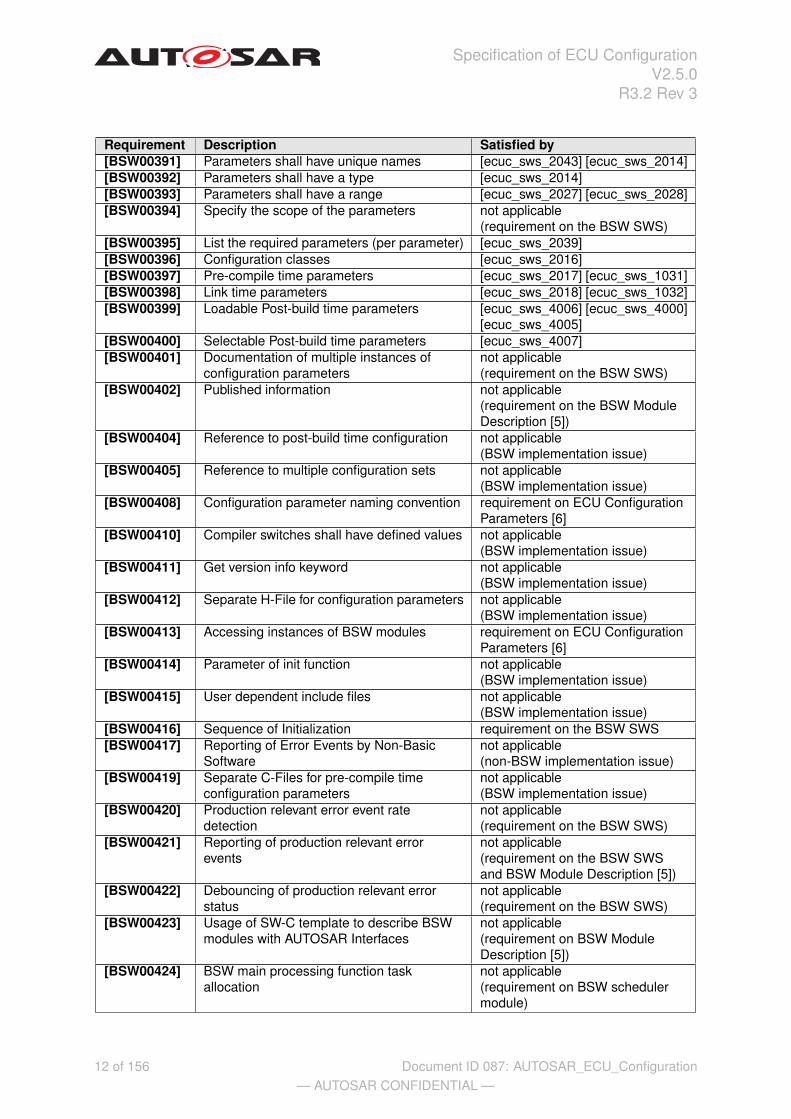
Requirement Description Satisfied by[BSW00391] Parameters shall have unique names [ecuc_sws_2043] [ecuc_sws_2014][BSW00392] Parameters shall have a type [ecuc_sws_2014][BSW00393] Parameters shall have a range [ecuc_sws_2027] [ecuc_sws_2028][BSW00394] Specify the scope of the parameters not applicable
(requirement on the BSW SWS)[BSW00395] List the required parameters (per parameter) [ecuc_sws_2039][BSW00396] Configuration classes [ecuc_sws_2016][BSW00397] Pre-compile time parameters [ecuc_sws_2017] [ecuc_sws_1031][BSW00398] Link time parameters [ecuc_sws_2018] [ecuc_sws_1032][BSW00399] Loadable Post-build time parameters [ecuc_sws_4006] [ecuc_sws_4000]
[ecuc_sws_4005][BSW00400] Selectable Post-build time parameters [ecuc_sws_4007][BSW00401] Documentation of multiple instances of
configuration parametersnot applicable(requirement on the BSW SWS)
[BSW00402] Published information not applicable(requirement on the BSW ModuleDescription [5])
[BSW00404] Reference to post-build time configuration not applicable(BSW implementation issue)
[BSW00405] Reference to multiple configuration sets not applicable(BSW implementation issue)
[BSW00408] Configuration parameter naming convention requirement on ECU ConfigurationParameters [6]
[BSW00410] Compiler switches shall have defined values not applicable(BSW implementation issue)
[BSW00411] Get version info keyword not applicable(BSW implementation issue)
[BSW00412] Separate H-File for configuration parameters not applicable(BSW implementation issue)
[BSW00413] Accessing instances of BSW modules requirement on ECU ConfigurationParameters [6]
[BSW00414] Parameter of init function not applicable(BSW implementation issue)
[BSW00415] User dependent include files not applicable(BSW implementation issue)
[BSW00416] Sequence of Initialization requirement on the BSW SWS[BSW00417] Reporting of Error Events by Non-Basic
Softwarenot applicable(non-BSW implementation issue)
[BSW00419] Separate C-Files for pre-compile timeconfiguration parameters
not applicable(BSW implementation issue)
[BSW00420] Production relevant error event ratedetection
not applicable(requirement on the BSW SWS)
[BSW00421] Reporting of production relevant errorevents
not applicable(requirement on the BSW SWSand BSW Module Description [5])
[BSW00422] Debouncing of production relevant errorstatus
not applicable(requirement on the BSW SWS)
[BSW00423] Usage of SW-C template to describe BSWmodules with AUTOSAR Interfaces
not applicable(requirement on BSW ModuleDescription [5])
[BSW00424] BSW main processing function taskallocation
not applicable(requirement on BSW schedulermodule)
12 of 156— AUTOSAR CONFIDENTIAL —
Document ID 087: AUTOSAR_ECU_Configuration

Specification of ECU ConfigurationV2.5.0
R3.2 Rev 3
Requirement Description Satisfied by[BSW00425] Trigger conditions for schedulable objects not applicable
(requirement on BSW ModuleDescription [5])
[BSW00426] Exclusive areas in BSW modules not applicable(requirement on BSW ModuleDescription [5] and BSWimplementation issue)
[BSW00427] ISR description for BSW modules not applicable(requirement on BSW ModuleDescription [5])
[BSW00428] Execution order dependencies of mainprocessing functions
not applicable(requirement on BSW ModuleDescription [5])
[BSW00429] Restricted BSW OS functionality access not applicable(BSW implementation issue)
[BSW00431] The BSW Scheduler module implementstask bodies
not applicable(requirement on BSW schedulermodule)
[BSW00432] Modules should have separate mainprocessing functions for read/receive andwrite/transmit data path
not applicable(BSW implementation issue)
[BSW00433] Calling of main processing functions not applicable(BSW implementation issue)
[BSW00434] The Schedule Module shall provide an APIfor exclusive areas
not applicable(BSW implementation issue)
[BSW159] Tool-based configuration [ecuc_sws_1030] [ecuc_sws_1000][BSW167] Static configuration checking [ecuc_sws_1000][BSW170] Data for reconfiguration of AUTOSAR
SW-Componentsnot applicable(requirement on theSoftware-Component Template [7])
[BSW171] Configurability of optional functionality [ecuc_sws_2009] [ecuc_sws_1000][ecuc_sws_1002] [ecuc_sws_1010][ecuc_sws_1012]
[ECUC0002] Support of vendor-specific ECUConfiguration Parameters
[ecuc_sws_1029] [ecuc_sws_1001][ecuc_sws_1002] [ecuc_sws_1011][ecuc_sws_1013] [ecuc_sws_1014][ecuc_sws_1015] [ecuc_sws_5001][ecuc_sws_5002] [ecuc_sws_5003]
[ECUC0008] Definition of post-build time changeableconfiguration of BSW
[ecuc_sws_2019] [ecuc_sws_4006][ecuc_sws_4000]
[ECUC0012] One description mechanism for differentconfiguration classes
[ecuc_sws_2016]
[ECUC0015] Configuration of multiple instances of BSWmodules
[ecuc_sws_2059] [ecuc_sws_2008]
[ECUC0016] Execution order of runnable entities not applicable(requirement on ECU ConfigurationParameters [6])
[ECUC0018] Extension handling fulfilled by the Model PersistenceRules for XML [8]
[ECUC0021] Select Application SW Component andBSW module implementation
[ecuc_sws_1036] [ecuc_sws_1029]
[ECUC0025] Compatible with iterative design [ecuc_sws_1027] [ecuc_sws_4000]
13 of 156— AUTOSAR CONFIDENTIAL —
Document ID 087: AUTOSAR_ECU_Configuration

Specification of ECU ConfigurationV2.5.0
R3.2 Rev 3
Requirement Description Satisfied by[ECUC0029] Identify mechanisms not criteria proceeding was followed in the
development of the ECUConfiguration Specification
[ECUC0030] Clarify configuration terminology terms defined in AUTOSARGlossary [2]
[ECUC0032] ECU Configuration Description shall be theroot for the whole configuration informationof an ECU
[ecuc_sws_2003] [ecuc_sws_1029]
[ECUC0039] Support configuration of BSW requirement on ECU ConfigurationParameters [6] [ecuc_sws_1029]
[ECUC0040] Support configuration of RTE requirement on ECU ConfigurationParameters [6] [ecuc_sws_1029]
[ECUC0041] Support AUTOSAR SW ComponentIntegration
requirement on ECU ConfigurationParameters [6]
[ECUC0043] Duplication free description [ecuc_sws_1027] [ecuc_sws_1028][ecuc_sws_1031]
[ECUC0046] Support definition of configuration class [ecuc_sws_2016][ECUC0047] Pre-compile time configuration of BSW [ecuc_sws_2017] [ecuc_sws_1031][ECUC0048] Link time configuration of BSW [ecuc_sws_2018] [ecuc_sws_1032][ECUC0049] ECU Configuration description shall be tool
processable[ecuc_sws_2001] [ecuc_sws_1030]
[ECUC0050] Specify ECU Configuration ParameterDefinition
[ecuc_sws_2045]
[ECUC0053] Support for multiple configuration sets not applicable(feature 128 canceled)
[ECUC0055] Support mandatory and optionalconfiguration parameters
[ecuc_sws_3011] [ecuc_sws_3010][ecuc_sws_3030] [ecuc_sws_2009][ecuc_sws_1002]
[ECUC0065] Development according to the AUTOSARMetamodeling Guide
[ecuc_sws_2000]
[ECUC0066] Transformation of ECUC modelingaccording to the AUTOSAR ModelPersistence Rules for XML
[ecuc_sws_2001]
[ECUC0070] Support mandatory and optional containers [ecuc_sws_2009] [ecuc_sws_1003][ECUC0071] Support for Generic Configuration Editor [ecuc_sws_1031][ECUC0072] Support for referencing from dependent
containers[ecuc_sws_3027] [ecuc_sws_3033][ecuc_sws_2039]
[ECUC0073] Support Service Configuration of AUTOSARSW Components
postponed; no concept availableyet
[ECUC0074] Support Sequential ECU Configuration [ecuc_sws_1031]
14 of 156— AUTOSAR CONFIDENTIAL —
Document ID 087: AUTOSAR_ECU_Configuration
Specification of ECU ConfigurationV2.5.0
R3.2 Rev 3
2 ECU Configuration Methodology
ECU Configuration is one step in the overall AUTOSAR methodology, which is de-scribed in [1]. Figure 1.1 already introduced in chapter 1 is taken from that documentand shows the most abstract view of the methodology. In this document, the activi-ties regarding configuring an ECU and generate the configuration data will be definedin more detail than provided in [1]. To understand this chapter, the reader should befamiliar with [1].
2.1 Notation used
Figure 1.1 and all other figures taken from the AUTOSAR Methodology [1] use a formalnotation called SPEM (Software Process Engineering Meta-Model), explained in detailin [1]. The SPEM elements used in this document are
• Work products (blue document shaped elements),
• Activities (block arrows) and
• Guidances (set square) to depict tools, attached to the activity they support by adashed line.
The flow of work products is depicted by solid lines with arrow heads, pointing in the di-rection of the work flow. Dependencies are depicted by dashed lines with arrow heads,pointing from the dependent element to the element it depends on. Compositions aredepicted by a solid line with a solid diamond on the end of the aggregating element.
2.2 Inputs to ECU Configuration
[ecuc_sws_1036] ECU Configuration has two input sources. First of all, all configura-tion that must be agreed across ECUs is defined in the System Configuration, whichresults in a System Configuration Description (and the resulting ECU Ex-tract of the System Configuration for the individual ECUs). Secondly, theECU BSW is built using BSW modules. The specifics of these module implementa-tion are defined in the BSW Module Descriptions (not shown in figure 1.1, seefigure 2.7). The latter is described in [9] in more detail. The concept of the ECU extractis depicted below:
15 of 156— AUTOSAR CONFIDENTIAL —
Document ID 087: AUTOSAR_ECU_Configuration

Specification of ECU ConfigurationV2.5.0
R3.2 Rev 3
ECU Extract of System Description
ECU Configuration can only be started once a plausible System ConfigurationDescription and the corresponding ECU extract has been generated (see fig-ure 1.1). Details on the System Configuration Description can be foundin [10]. The System Configuration Description contains all relevant system-wide configuration, such as
• ECUs present in the system
• Communication systems interconnecting those ECUs and their configuration
• Communication matrices (frames sent and received) for those communicationsystems
• Definition of Software Components with their ports and interfaces and connec-tions (defined in the SWC Description and referenced in the System Configu-ration Description).
• Mapping of SWCs to ECUs
The ECU Extract of the System Configuration is a description in the sameformat as the System Configuration Description, but with only those ele-ments included that are relevant for the configuration of one specific ECU.
2.3 ECU Configuration
ECU Configuration can be broken down into three activities, as shown in figure 2.1:
.XML.XML
ECU
Configuration
Description
AUTOSAR
ECU
Configuration
Editors
Generate
Base ECU
Configuration
Description
Edit ECU
Configuration
.XML.XML
ECU
Extract
of
System
Configuration
:
System
Generate
Configured
Module
Code
.c.c
Module
Code
.h.h
Module
Headers
Figure 2.1: ECU Configuration broken down into three sub-activities
• Generate Base ECU Configuration Description
• Edit ECU Configuration
• Generate Configured Module Code
16 of 156— AUTOSAR CONFIDENTIAL —
Document ID 087: AUTOSAR_ECU_Configuration

Specification of ECU ConfigurationV2.5.0
R3.2 Rev 3
[ecuc_sws_1027] All three activities use a single work product, the ECU Configura-tion Description, which contains (i.e. references) all the configuration informationfor all BSW modules on the ECU. In order to better understand the three different ac-tivities an introduction to configuration classes is essential. In a real implementation ofa BSW module all configuration parameters are most likely not the same configurationclass. I.e it will be a mix of parameters with different configuration classes within aBSW module.
These three activities are introduced in detail in later sections, but first is an introductionto ECU configuration description and configuration classes.
2.3.1 ECU Configuration Description
The ECU Extract of System Configuration only defines the configuration el-ements that must be agreed between ECUs. In order to generate a working executablethat runs on the ECU, much more configuration information must be provided.
The remaining part of the configuration is about configuring all BSW modules withinthe ECU. Typical BSW modules within an ECU can be: RTE, Com, Can, OS, NVRAMetc. There are also dependencies between BSW modules to consider when configur-ing the ECU. When the configuration is done, the generation of configuration data takesplace. I.e. there are both configuration editors and configuration generators involvedin the process. In order to obtain consistency within the overall configuration of theECU, AUTOSAR has defined a single format, the ECU Configuration Descrip-tion to be used for all BSW modules within an ECU. Both configuration editors andconfiguration generators are working toward ECU Configuration Descriptions.
[ecuc_sws_1028] This one description (ECU Configuration Description) col-lects the complete configuration of BSW modules in a single ECU. Each module gener-ator may then extract the subset of configuration data it needs from that single format.
2.3.2 Introduction To Configuration Classes
The development of BSW modules involve the following development cycles: com-piling, linking and downloading of the executable to ECU memory. Configuration ofparameters can be done in any of these process-steps: pre-compile time, link timeor even post-build time. According to the process-step that does the configuration ofparameters, the configuration classes are categorized as below
• pre-compile time
• link time
• post-build time
The configuration in different process-steps has some consequences for the handlingof ECU configuration parameters. If a configuration parameter is defined as pre-
17 of 156— AUTOSAR CONFIDENTIAL —
Document ID 087: AUTOSAR_ECU_Configuration

Specification of ECU ConfigurationV2.5.0
R3.2 Rev 3
compile time, after compilation this configuration parameter can not be changed anymore. Or if a configuration parameter is defined at post-build time the configurationparameter has to be stored at a known memory location. Also, the format in whichthe BSW module is delivered determines in what way parameters are changeable. Asource code delivery or an object code delivery of a BSW module has different degreesof freedom regarding the configuration.
The configuration class of a parameter is typically not fixed in the standardized param-eter definition since several variants are possible. However once the module is imple-mented the configuration class for each of the parameters is fixed in that implemen-tation. Choosing the right configuration class from the available variants is dependingon the type of application and the design decisions taken by the module implementer.Different configuration classes can be combined within one module. For example, forpost-build time configurable BSW implementations only a subset of the parametersmight be configurable post-build time. Some parameters might be configured as pre-compile time or link time.
Output file formats used for describing the configuration classes:
• .xml (An xml file standardized by AUTOSAR.)
• .exe (An executable that can be downloaded to an ECU.)
• .hex (A binary file that can be downloaded to an ECU , but it can not execute byits own.)
• .c (A C-source file containing either source code or configuration data.)
• .h (A header file for either source code or configuration data.)
• .obj (A object file for either source code or configuration data.)
18 of 156— AUTOSAR CONFIDENTIAL —
Document ID 087: AUTOSAR_ECU_Configuration

Specification of ECU ConfigurationV2.5.0
R3.2 Rev 3
2.3.2.1 Configuration Class pre-compile time
.XML.XML
ECU
Configuration
Description
.h.h
BSW1
Configuration
Header
.c.c
BSW1
Code
Generate
BSW1
Configuration
BSW1
Configuration
Generator
.h.h
BSW2
Configuration
Header
.c.c
BSW2
Generated
Configured
Code
Generate
BSW2
BSW2
Configuration
Generator
Compile
BSW1
Compile
BSW2
.obj.obj
BSW1
Object
Code
.obj.obj
BSW2
Obj ect
Code
Link ECU
Code
C
Compiler
Linker
.exe.exe
ECU
Executable
Figure 2.2: Pre-compile time configuration chain
[ecuc_sws_1031] This type of configuration is a standalone configuration done be-fore compiling the source code. That means parameter values for those configurableelements are selected before compiling and will be effective after compilation time.The value of the configurable parameter is decided in earlier stage of software devel-opment process and any changes in the parameter value calls for a re-compilation.The contents of pre-compile time parameters can not be changed at the subsequentdevelopment steps like link time or post-build time.
Example BSW1 in figure 2.2 shows one possible approach to implement pre-compiletime parameters. Configurable parameter values will be kept in a configuration headerfile and compiled along with the module source file, which is not touched by the BSW1Configuration Generator. Example BSW2 in figure 2.2 shows an alternativeapproach, in which the BSW2 Configuration Generator generates the complete,configuration-specific code. Both approaches are equally valid.
Whenever the decision of parameter value must be taken before the selection of otherdependable parameters, pre-compile time configuration is the right choice. For exam-ple, the algorithm choice for CRC initial checksum parameter is based on the selectionof CRC type (CRC16 or CRC32). When CRC16 is selected, there will be increase inprocessing time but reduction in memory usage. Whereas when CRC32 is selected,there will be decrease in processing time but increase in memory usage. The correctchoice should be made by the implementer before compilation of source code basedon the requirement and resource availability.
Sample cases where pre-compile time configuration can be adopted are listed below:
19 of 156— AUTOSAR CONFIDENTIAL —
Document ID 087: AUTOSAR_ECU_Configuration

Specification of ECU ConfigurationV2.5.0
R3.2 Rev 3
• Configure the number of memory tables and block descriptor table of NVRAMmanager.
• Enable the macro for the development error tracing of the software modules.
20 of 156— AUTOSAR CONFIDENTIAL —
Document ID 087: AUTOSAR_ECU_Configuration

Specification of ECU ConfigurationV2.5.0
R3.2 Rev 3
2.3.2.2 Configuration Class link time
.h.h
BSW3
Header
.c.c
BSW3
Code
.h.h
BSW3
Configuration
Header
.c.c
BSW3
Configuration
Data
Generate
BSW3
Configuration
BSW3
Configuration
Generator
Compile
BSW3
Unconfigured
Code
Compile
BSW3
Configuration
C
Compiler
.obj.obj
BSW3
Obj ect
Code
.obj.obj
BSW3
Configuration
Obj ect
Code
.XML.XML
ECU
Configuration
Description
Link ECU
Code
Linker.exe.exe
ECU
Executable
Figure 2.3: Link time configuration chain
[ecuc_sws_1032] This type of configuration is done for the BSW module during linktime. That means the object code of the BSW module receives parts of its configurationfrom another object code file or it is defined by linker options. Link time parameters aretypically used when delivering object code to the integrator.
This configuration class provides a modular approach to the configuration process. Aseparate module will handle the configuration details and those parameter values willbe made available to the other modules during the linking process.
In figure 2.3 the configuration parameter data is defined in a common header file (BSW3Header) and included by both module source file (BSW3 Code) and module configu-ration source file (BSW3 Configuration Data). The module source file needs thisheader file to resolve the references and module configuration source file will need itin order to cross check the declaration of data type against the definition. Both modulesource file and module configuration source file are compiled separately and generatesmodule object file and module configuration object file respectively. During the linkingprocess, the configuration data will be available to module object file by resolving theexternal references. When the value of configuration parameters is to be changed themodule configuration object file needs to be replaced by the one containing the newparameters.
Sample cases where Link time configuration can be adopted are listed below:
• Initial value and invalid value of signal.
• Unique channel identifier configured for the respective instance of the NetworkManagement.
21 of 156— AUTOSAR CONFIDENTIAL —
Document ID 087: AUTOSAR_ECU_Configuration

Specification of ECU ConfigurationV2.5.0
R3.2 Rev 3
• Logical handle of CAN network.
• Identifier and type of Hardware Reception Handle and Hardware TransmissionHandle for CAN interface.
• Definition of ComFilterAlgorithm.
• COM callback function to indicate RTE about the reception of an invalidated sig-nal.
2.3.2.3 Post-build Configuration
There are two kinds of post-build configuration defined. They are:
• Post-build time loadable.
• Post-build time selectable.
For the methodology it is essential to distinguish between PostBuildLoadable andPostBuildSelectable.
For the standardized ECU Configuration Parameter Definition the configuration classesPostBuildLoadable and PostBuildSelectable are no longer required becausethe difference between these two configuration classes is only relevant for the memorymapping of the configuration data during linking. In the VSMD the distinction is stillmade as described in chapter 5.1.
22 of 156— AUTOSAR CONFIDENTIAL —
Document ID 087: AUTOSAR_ECU_Configuration
Specification of ECU ConfigurationV2.5.0
R3.2 Rev 3
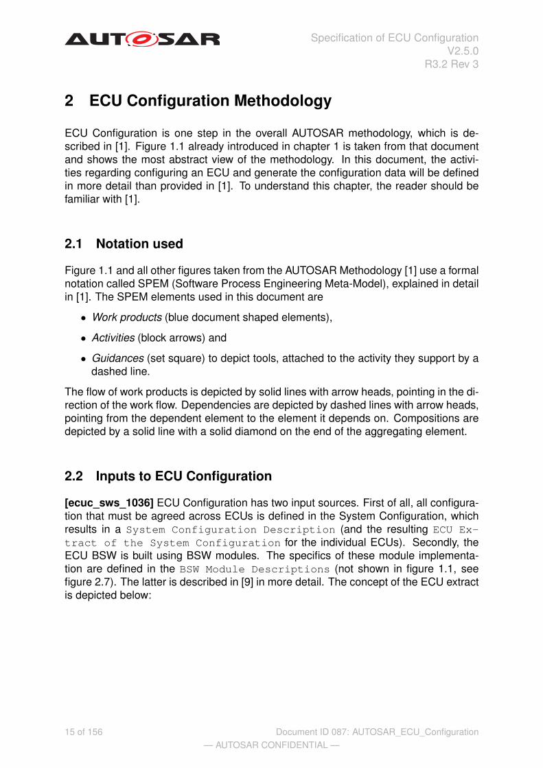
2.3.2.3.1 Configuration Class post-build time loadable
[ecuc_sws_4006] This type of configuration is possible after building the BSW moduleor the ECU software. The BSW module gets the parameters of its configuration bydownloading a separate file to the ECU memory separately, avoiding a re-compilationand re-build of the BSW module.
In figure 2.4 one approach of post-build time loadable is described.
C
Compiler
.XML.XML
ECU
Configuration
Description
Link ECU
Code
.c.c
BSW4
CodeCompile
BSW4
Unconfigured
Code
.obj.obj
BSW4
Object
Code
.h.h
BSW4
Configuration
Header
.c.c
BSW4
Configuration
Data
Generate
BSW4
Configuration
BSW4
Configuration
Generator
Compile
BSW4
Configuration
.obj.obj
BSW4
Configuration
Object
Code
Link Post-
Build
Configuration
.hex.hex
BSW4
Configuration
Loadable
to ECU
Memory
.h.h
BSW4
Header
Linker
.exe.exe
ECU
Executable
Figure 2.4: Post-build time loadable configuration chain
In order to make the post-build time loadable re-configuration possible, the re-configurable parameters shall be stored at a known memory location of the ECU mem-ory. An example is shown in figure 2.4. The BSW4 source code (BSW4 Code) iscompiled and linked independently of its configuration data. The BSW4 Configura-tion Generator generates the configuration data as normal C source code (BSW4Configuration Data) that is compiled and linked independently of the sourcecode. The configuration data, BSW4 Configuration Loadable to ECU Mem-ory, is stored at a known memory location and it is possible to exchange the con-figuration data without replacing the ECU Executable.
Another approach of post-build time loadable is shown in figure 2.5.
23 of 156— AUTOSAR CONFIDENTIAL —
Document ID 087: AUTOSAR_ECU_Configuration

Specification of ECU ConfigurationV2.5.0
R3.2 Rev 3
.XML.XML
ECU
Configuration
Description
Generate
BSW5
Configuration
BSW5
Configuration
Generator
.hex.hex
BSW5
Configuration
Loadable
to ECU
Memory
C
Compiler
Link ECU
Code
.c.c
BSW5
Code
Compile
BSW5
Unconfigured
Code
.obj.obj
BSW5
Obj ect
Code
Linker
.exe.exe
ECU
Executable
Figure 2.5: Post-build time loadable configuration chain
The difference compared to the other approach is that the BSW5 ConfigurationGenerator does perform the tasks performed by the compiler and linker in the priorapproach. I.e the BSW5 Configuration Loadable to ECU Memory is generateddirectly from the generator. The configuration data and the executable is still indepen-dently exchangeable.
Sample cases where post-build time loadable configuration can be adopted are listedbelow.
• Identifiers of the CAN frames
• CAN driver baudrate and propagation delay
• COM transmission mode, transmission mode time offset and time period
24 of 156— AUTOSAR CONFIDENTIAL —
Document ID 087: AUTOSAR_ECU_Configuration

Specification of ECU ConfigurationV2.5.0
R3.2 Rev 3
2.3.2.3.2 Configuration Class post-build time selectable
[ecuc_sws_4007]Post-build time selectable makes it possible to define multiple con-figuration sets. Which set that will become active is choosen during boot-time. Adescription of post-build time selectable is shown in figure 2.6.
Link ECU
Code
Linker
.XML.XML
ECU
Configuration
Description
C
Compiler
Generate
BSW6
Configuration
BSW6
Configuration
Generator
.c.c
BSW6 Code
.c.c
BSW6
Configuration
Data [Set 1]
.c.c
BSW6
Configuration
Data [Set 2]
Compile BSW6
Configuration
.obj.obj
BSW6
Obj ect Code
Compile BSW6
Unconfigured
Code
.obj.obj
BSW6
Configuration
Obj ect Code
.exe.exe
ECU
Executable
incl.
Configuration
Sets
Figure 2.6: Post-build time selectable configuration chain
In the example the BSW6 Configuration Generator generates two sets of con-figuration parameters. The configuration data is compiled and linked together with thesource code of the BSW module (BSW6 Code). The resulting executable, ECU Ex-ecutable incl.Configuration Sets, includes all configuration sets as well asthe source code of the BSW module. I.e. it is not possible to exchange the configura-tion data without re-building the entire executable. It is only possible to choose betweenthe provided parameter sets without individually changing the values of configurationparameters. This choice is done during Module initialization.
25 of 156— AUTOSAR CONFIDENTIAL —
Document ID 087: AUTOSAR_ECU_Configuration

Specification of ECU ConfigurationV2.5.0
R3.2 Rev 3
2.3.3 Generate Base ECU Configuration Description
.XML.XML
Vendor
Specific
Module
Definition
:
ModuleDef
.XML.XML
BSW-
Module
Description
:
BswModuleDescription
.XML.XML
Vendor
Specific
Preconfigured
Configuration
Description
:
ModuleConfiguration
.XML.XML
Standardized
ECU
Configuration
Parameter
Definition
:
EcuParameterDefinition
.XML.XML
ECU
Configuration
Description
AUTOSAR
ECU
Configuration
Editors
Generate
Base ECU
Configuration
Description
Edit ECU
Configuration
.XML.XML
ECU
Extract
of
System
Configuration
:System
.XML.XML
Vendor
Specific
Recommended
Configuration
Description
:
ModuleConfiguration
.XML.XML
Standardized
Module
Definition
:
ModuleDef
Figure 2.7: Generation of the base ECU Configuration Description
The first step in the process of ECU configuration is to generate the base ECU Con-figuration Description. This step involves the generation of the ECU Compo-sition. See chapter 2.3.3.1
The ECU Configuration Description contains (i.e. references) the configura-tion of all BSW modules present on the ECU. The configuration of the different BSWmodules is done in different sections of the overall description. The section for aspecific BSW module in the base ECU Configuration Description can be gen-erated using the Vendor Specific ECU Configuration Parameter Defini-tion (referenced via the BSW Module Description BSWMD for that module) andthe ECU Extract of the System Configuration, as input, see figure 2.7. Thisgeneration is a semi-automatic process.
[ecuc_sws_1029] For each BSW module that shall be present in the ECU, the imple-mentation must be chosen. This is done by referencing the BSWMD delivered withthe BSW module. The BSWMD defines all configuration parameters, and their struc-turing in containers, relevant for this specific implementation of the module. This isdone in the Vendor Specific Module Definition. The rules that must be fol-
26 of 156— AUTOSAR CONFIDENTIAL —
Document ID 087: AUTOSAR_ECU_Configuration

Specification of ECU ConfigurationV2.5.0
R3.2 Rev 3
lowed when building the base ECU Configuration Description are available inchapter 5.2.
2.3.3.1 Generating the ECU Composition
In the ECU Extract of the System Configuration only the application Soft-ware Components are considered. The RTE and all BSW modules are not taken intoaccount in the System Configuration. In ECU Configuration all aspects of theECU software need to be considered, therefore means to support the addition of theBSW and RTE need to be provided.
In the ECU Configuration Description an additional hierarchical level is intro-duced which defines the Application SW-Component instances (EcuTopLevelComposi-tionPrototype) and the AUTOSAR BSW Service instances (see figure 2.8 EcuSwCom-position). AUTOSAR BSW Services are modules like the NvRam Manager, the Watch-dog Manager, the ECU State Manager, etc.
Figure 2.8: Structure of the EcuComposition introduced in the ECU Configuration
[ecuc_sws_2085] When generating the Base ECU Configuration theEcuSwComposition is introduced, which defines one additional level of hierar-chy for SW-Components.
[ecuc_sws_2087] The EcuSwComposition contains the SW-Component descrip-tions of the application SW-Component prototypes, the AUTOSAR BSW Service mod-ules prototypes and the connections between the Application SW-Component portsand the BSW Service modules’ ports.
[ecuc_sws_2086] The TopLevelComposition is instantiated in the EcuSwCompo-sitionwith the ComponentPrototype name EcuTopLevelCompositionProto-type.
The TopLevelComposition is defined in the System Description ([10]) using themeans of the SW-Component template [7]. The instantiation is done by defining aComponentPrototype using the mechanisms defined in the SW-Component tem-plate.
27 of 156— AUTOSAR CONFIDENTIAL —
Document ID 087: AUTOSAR_ECU_Configuration

Specification of ECU ConfigurationV2.5.0
R3.2 Rev 3
When generating the AUTOSAR BSW Services SW-Components the actual needs1
from the Application SW-Components are collected and an appropriate number of portsis created at each BSW Service SW-Component.
The connections of the Application SW-Component ports to the BSW Service ports arespecial, because it is allowed to connect ports which are on different levels of hierarchy(this is not allowed in the plain SW-Component descriptions).
2.3.4 Edit ECU Configuration
The second step in the process of ECU configuration is to edit the configuration pa-rameters for all BSW modules.
[ecuc_sws_1030] Once the section for a specific BSW module has been generatedin the base ECU Configuration Description, it can be edited with AUTOSARECU Configuration Editors. Those editors may operate with user interaction,semi automatically or automatically, depending on BSW module and implementation.A straightforward approach editing the ECU Configuration Description is de-scribed in figure 2.1.
2.3.4.1 Details in Edit ECU Configuration
Editing the ECU Configuration is a process that has some aspects which put specificrequirements on tools and workprocedures. One aspect is the iterative process whenediting ECU configuration parameters and another aspect is support for configurationmanagement.
2.3.4.1.1 Iterations within ECU Configuration
What appears clear is that there are likely to be both optimizations and trade-offs to bemade between parameters, both within and between BSW modules. The configurationdeals with, for example, detailed scheduling information or the configuration data forthe needed BSW modules. Hence this is a non-trivial design step and requires com-plex design algorithms and/or engineering knowledge. ECU Configuration is thus likelyto be an iterative process. This iteration will initially be between editors and then, whena plausible ECU Configuration is achieved, code generation may highlight additionalchanges that require further iteration. It is hoped that the majority of generator-editoriterations will be limited by ensuring that the editor tools are capable of spotting/pre-dicting potential generator errors and ensuring that the engineer corrects them prior toentering generation.
1The needs of the Application SW-Components are defined in the SW-Component description in theServiceNeeds section.
28 of 156— AUTOSAR CONFIDENTIAL —
Document ID 087: AUTOSAR_ECU_Configuration

Specification of ECU ConfigurationV2.5.0
R3.2 Rev 3
EcuC1
MCAL
Configuration Editor
EcuC1
COM
Configuration Editor
EcuC1
OS
Configuration Editor
….
Updated ECU
Configuration
Updated ECU
Configuration
Updated ECU
Configuration
Iteratively complete ECU Configuration with respect to different configuration parameters
Figure 2.9: Sequential Application of tools
Figure 2.9 shows how a set of custom tools might be used in a chain with iteration inorder to achieve a successful ECU Configuration. Tools are sequentially called withina tool chain to create an ECU Configuration Description. Iteration cycles mustbe implemented by repeated activation of different configuration tools for specific as-pects of the BSW. Dependencies between tools, as well as the configuration work flow,might need to be expressed explicitly. Configuration tools are required only to supporta single standardized interface, the ECU Configuration Description Template.
Tools supporting the methodology and the iterations needed for ECU configuration canbe designed based on different strategies. Chapter A.1.1 gives som information aboutthis topic.
Iterations can be divided between several organizations due to the fact that parameterswithin a BSW module are either configured pre-compile time, link time, post-build-selecttime or post-build-load time.
Typically the following cases apply:
• values of preconfigured pre-compile-time-parameters are set by a Tier2 supplier.
• values of all other pre-compile-time-parameters are set by a Tier 1 supplier, typi-cally according to the requirements of the OEM.
• values of link-time-parameters are set by a Tier 1 supplier, typically according therequirements of the OEM.
• values of postbuild-selectable parameters are set by a Tier 1 supplier, typicallyaccording to the requirements of the OEM and delivered as part of the regularECU-Executable.
• values of postbuild-loadable parameters are set by either a Tier 1 supplier or bythe OEM depending on the business model respectively liability issues. Howeverthey are delivered as part of a separated Hex-File (called ECU-Executable inMethdololgy).
A description of editing ECU configuration parameters in an iterative manner with sev-eral organisations involved is described in figure 2.10.
Configuring of pre-compile time and post-build time parameters occur at different or-ganisations. The methodology supports parallel and iterative configuration activities. A
29 of 156— AUTOSAR CONFIDENTIAL —
Document ID 087: AUTOSAR_ECU_Configuration

Specification of ECU ConfigurationV2.5.0
R3.2 Rev 3
pre-compile time parameter can affect i.e. a post-build time parameter. The methodol-ogy supports description of dependencies between parameters.
Perform ed by OEMPerformed by T ier2 / T ier1
Performed by T ier2
Perform ed by OEM
Performed by T ier2 / T ier1
Performed by T ier2
.XML.XML
ECU
Configuration
Description
.XML.XML
BSW-
Module
Description
:
Bsw ModuleDescription
Generate Base ECU
Configuration Description
.XML.XML
ECU
Extract of
System
Configuration
:System
.XML.XML
Vendor
Specific
Module
Definition :
ModuleDef
.XML.XML
Vendor
Specific
Preconfigured
Configuration
Description
:
M oduleConfiguration
.XML.XML
Vendor
Specific
Recommended
Configuration
Description
:
M oduleConfiguration
Edit PC ECU
Configuration
.XML.XML
PC No Affect :
ModuleConfiguration
.XML.XML
PC Affect LT :
ModuleConfiguration
.XML.XML
PC Affect PB :
ModuleConfiguration
Edit LT ECU
Configuration
.XML.XML
LT No Affect :
ModuleConfiguration
.XML.XML
LT Affects PB :
ModuleConfiguration Edit PB ECU
Configuration
Generate Module
Configuration
Generate Module
Configuration
Generate M odule
Configuration
.c.c
Module
Configuration
Code
.h.h
Module
Configuration
Header
.obj.obj
Module
Configuration
Object
Code
.hex.hex
Module
Configuration
Loadable
to ECU
Memory
Figure 2.10: Detailed description of ECU configuration
30 of 156— AUTOSAR CONFIDENTIAL —
Document ID 087: AUTOSAR_ECU_Configuration

Specification of ECU ConfigurationV2.5.0
R3.2 Rev 3
2.3.4.1.2 Affection between parameters
The configuration class affection is deprecated and will be removed in futureversions!
The BSWMD (delivered by a Tier2 supplier) contains a description of the entire BSWmodule, including dependencies between parameters. Each parameter has an at-tribute that can be assigned one of these values:
• NO-AFFECT (The parameter has no affect on any other parameter)
• PC-AFFECTS-LT (A pre-compile time parameter affecting one or several link timeparameter(s))
• PC-AFFECTS-PB (A pre-compile time parameter affecting one or several post-build time parameter(s))
• PC-AFFECTS-LT-AND-PB (A pre-compile time parameter affecting one or severallink time and post-build time parameter(s))
• LT-AFFECTS-PB (A link time parameter affecting one or several post-build timeparameter(s))
In addition it is also possible to list the affected parameters in the BSWMD. The de-scription of dependencies makes it possible to inform about changes that will affectother organizations taking part in the ECU configuration.
[ecuc_sws_4000] In the figure 2.10 there are three activities defined: "‘Edit PC ECUConfiguration"’, "‘Edit LT ECU Configuration"’ and "‘Edit PB ECU Configuration"’.These activities are performed by different organisations. In order to transfer infor-mation from one step of the configuration to another, it is possible to generate a filecontaining parameters that affect another step of the configuration. This is done by i.e.generating the xml-file: "‘PC Affect PB"’. The xml-file is a ModuleConfigurationand contains the pre-compile time parameters that has an affect on post-build timeparameter(s) for a specific BSW module or cluster of BSW modules. Since the editor isthe same in all steps of the configuration of a BSW module or a cluster the "‘PC AffectPB"’ and all other files can be generated by any person or organisation using the editor.
After the first generation of the base ECU Configuration Description thedifferent organisations can start their part of the parameter configuration by editingthe ECU Configuration Description. The different organisations are mostlikely working with a local copy of the ECU Configuration Description. Even-tually there is a need to combine the local copies into one ECU ConfigurationDescription. This is done with a simple merge tool, that is a part of the ECUConfiguration Editor. The merging is easy since there should be no redun-dant sections. To ensure editing only pre-compile time, link time or post-build timeparameters, the ECU Configuration Editor shall be able to define a subset ofparameters that are allowed to be edited. The subset can be any combination ofpre-compile time, link time and post-build time parameters.
31 of 156— AUTOSAR CONFIDENTIAL —
Document ID 087: AUTOSAR_ECU_Configuration

Specification of ECU ConfigurationV2.5.0
R3.2 Rev 3
Requirements for ECU Configuration Editors supporting the methodology canbe found in chapter 5.3.
2.3.4.1.3 Configuration Management and Post-build Time Loadable
Post-build time loadable permits the change of configuration parameter values afterbuilding the rest of the ECU-SW (BSW modules and SW-Cs) by downloading a newconfiguration loadable to the ECU memory at a specific address. This implies thatthere are at least two SW articles with unique part numbers for an ECU if using thepost-build loadable strategy. (There can be more than two since every BSW modulecan theoretically be configured post-build time loadable). Since there are several SWarticles with unique part numbers there is a must to keep track of each SW articlefrom a Configuration Management perspective. In order to do this for each post-buildtime loadable, ModuleConfigurations describing different aspects (E.g the post-build aspect) of a BSW module needs to be put under Configuration Management asa separate file.
In figure 2.11 the relationships between ModuleConfigurations describing differ-ent aspects and the SW articles with their unique part numbers are shown. Note thatthe relationships are Configuration Management(CM) relations. This means if a pa-rameter in the ModuleConfiguration describing the post-build aspect is changed itis only needed to re-build the configuration data, the rest of the SW articles in the ECUremain untouched. If a parameter in a ModuleConfiguration describing the pre-compile aspect is changed the BSW module needs to be re-build. The configurationdata must also be re-build if the ModuleConfiguration contains e.g. a pre-compiletime parameter with the attribute "‘PC affects PB"’. See chapter 2.3.4.1.1. Each Mod-uleConfiguration describing a certain aspect, e.g the post-build aspect, must beput under Configuration Management as a Configuration Item(CI).
32 of 156— AUTOSAR CONFIDENTIAL —
Document ID 087: AUTOSAR_ECU_Configuration

Specification of ECU ConfigurationV2.5.0
R3.2 Rev 3
Figure 2.11: Configuration Items(CIs) and post-build time loadable configuration.
Another use case where ModuleConfigurations describing different aspects mustbe Configuration Items, is for different car models which can have different set of con-figuration data, but the rest of the SW in the ECU is the same for all car models. Seefigure 2.11.
Requirements for the ECU Configuration Editors supporting post-build timeloadable strategy can be found in chapter 5.3.
33 of 156— AUTOSAR CONFIDENTIAL —
Document ID 087: AUTOSAR_ECU_Configuration
Specification of ECU ConfigurationV2.5.0
R3.2 Rev 3
2.3.5 Generate Configured Module Code
The third and last step of the AUTOSAR ECU Configuration methodology has alreadybeen referenced in the preceding sections and so comes as no surprise. Generation ofconfigured module code for the different BSW modules. Generation is the process ofapplying the tailored ECU Configuration Description to the software modules.This can be performed in different ways, and is dependent on the configuration classeschosen for the different modules (see chapter 2.3.2), and on implementers choices.
For each BSW module, a generator reads the relevant parameters from the ECU Con-figuration Description and creates code that implements the specified config-uration, as shown on the right hand side of figures A.1 and A.2. In this generation step,the abstract parameters of the ECU Configuration Description are translatedto hardware and implementation-specific data structures that fit to the implementationof the corresponding software module. This specification does not specify the gener-ator tools in detail. It is assumed however that generators perform error, consistencyand completeness checks on the part of the configuration they require for generation.
There are some alternative approaches when it comes to generation of configurationdata. See chapter A.1.2 for more details.
34 of 156— AUTOSAR CONFIDENTIAL —
Document ID 087: AUTOSAR_ECU_Configuration
Specification of ECU ConfigurationV2.5.0
R3.2 Rev 3
3 Configuration Metamodel
3.1 Introduction
AUTOSAR exchange formats are specified using a metamodel based approach (seealso Specification of Interoperability of Authoring Tools [11]). The metamodel for theconfiguration of ECU artifacts uses an universal description language so that it is possi-ble to specify different kinds of configuration aspects. This is important as it is possibleto describe AUTOSAR-standardized and vendor-specific ECU Configuration Parame-ters with the same set of language elements. This eases the development of tools andintroduces the possibility to standardize vendor-specific ECU Configuration Parametersat a later point in time.
In general the configuration language uses containers and actual parameters. Contain-ers are used to group corresponding parameters. Parameters hold the relevant valuesthat configure the specific parts of an ECU. Due to the flexibility that has to be achievedby the configuration language the configuration description is divided into two parts:
• ECU Configuration Parameter Definition
• ECU Configuration Description
A detailed description of these two parts and their relationships are presented in thefollowing sections.
3.2 ECU Configuration Template Structure
In this section the relationships between the different AUTOSAR templates involvedin the ECU Configuration are introduced. A template is defining the structure andpossible content of an actual description. The concept is open to be implemented inseveral possible ways, in AUTOSAR XML files have been chosen to be used for theexchange formats. If XML files are used there is no conceptual limit in the number offiles making up the description. All the contributing files are virtually merged to buildthe actual description1.
The goal of the ECU Configuration Description template is to specify an exchangeformat for the ECU Configuration Values of one ECU. The actual output of ECU Con-figuration editors is stored in the ECU Configuration Description, which might be oneor several XML files. But the ECU Configuration editors need to know how the contentof an ECU Configuration Description should be structured (which parameters are avail-able in which container) and what kind of restrictions are to be respected (e.g. the ECUConfiguration Parameter is an integer value in the range between 0 and 255). This isspecified in the ECU Configuration Parameter Definition which is also an XML file. Therelationship between the two file types is shown in figure 3.1.
1The rules are defined in the Specification of Interoperability of Authoring Tools document [11].
35 of 156— AUTOSAR CONFIDENTIAL —
Document ID 087: AUTOSAR_ECU_Configuration

Specification of ECU ConfigurationV2.5.0
R3.2 Rev 3
Figure 3.1: Parameter Definition and ECU Configuration Description files
For the ECU Configuration editors there are basically two possible approaches how toimplement these definitions. Either the ECU Configuration Parameter Definition is readand interpreted directly from the XML file or the defined structures are hard-coded intothe tool2.
For the development of the ECU Configuration Parameter Definition and the ECU Con-figuration Description a model-based approach has been chosen which already hasbeen used during the development of other AUTOSAR template formats.
The main approach is to use a subset of UML to graphically model the desired enti-ties and their relationships. Then, in a generation step, the actual XML formats areautomatically generated out of the model.
[ecuc_sws_2000] The modeling of the ECU Configuration Description and ECU Con-figuration Parameter Definition metamodels is done according to the Template UMLProfile and Modeling Guide [12].
[ecuc_sws_2001] The transformation of the ECU Configuration Description and ECUConfiguration Parameter Definition metamodels to schema definitions is done accord-ing to the Model Persistence Rules for XML [8].
Because of these transformation rules there is a given discrepancy between the UMLmodel and the generated XML-Schema names. This also affects this document. Themajor descriptions will be based on the UML model notations (figures and tables),although the corresponding XML notation might be given for reference purposes.
In this section the application of the modeling approach for the ECU Configuration isdescribed.
AUTOSAR uses the UML metamodel (M2-level) to describe the classes and objectsthat may be used in an AUTOSAR-compliant system. These metamodel elementsmay be used in an application model (M1-level) to describe the content of a real vehi-cle. ECU Configuration is a part of the AUTOSAR standard so the elements of ECUConfiguration Description must be described in the UML metamodel at M2-level. The(M2) metamodel has therefore been populated with UML descriptions from which ECUConfiguration Parameter models may be built.
2The advantage of using the interpreter is that changes on the ECU Configuration Parameter Defini-tion are directly available in the tool. But the hard-coded approach allows for more custom user supportin the tool
36 of 156— AUTOSAR CONFIDENTIAL —
Document ID 087: AUTOSAR_ECU_Configuration

Specification of ECU ConfigurationV2.5.0
R3.2 Rev 3
With M2 definitions in place, it is possible to create AUTOSAR-conforming modelsof real application ECU Configuration Parameters (an ECU Configuration ParameterDefinition Model) at M1-level. Certain aspects of real application configurations arealready defined: BSW Modules have standard interfaces and configuration require-ments. These ’real’ configuration parameters have therefore already been modeledat M1-level for each defined BSW Module. These are described in detail in the SWSdocuments.
XML has been chosen as the technology that will be used by AUTOSAR-complianttools in order to define and share information during an AUTOSAR-compliant systemdevelopment. It must therefore be possible to transform the UML Configuration Pa-rameter Definition Model (M1-level) into an XML Configuration Parameter Definition sothat it may be used by ECU Configuration tools. This is the way that the tool gets adefinition of exactly which ECU Configuration Parameters are available and how theymay be configured. The Model Persistence Rules for XML [8] describes how the UMLmetamodel (M2-level) may be transformed into a schema that describes the format ofXML to contain model elements.
This same formalization is also true for the ECU Configuration Parameter DefinitionMetamodel elements on M2-level: the Model Persistence Rules for XML dictates howECU Configuration Parameter Definition elements will generate a schema to hold ECUConfiguration Parameter Model (M1-level) elements in an XML ECU Configuration Pa-rameter Definition, that can then be interpreted by ECU Configuration tools.
ECU Configuration editors allow a system designer to set ECU Configuration Parame-ter Values for their particular application. The actual values are then stored in an ECUConfiguration Description that conforms to the template described in the UML.
An ECU Configuration Description is an XML file that conforms to an AUTOSAR sche-ma called an ECU Configuration Description Template. The template in turn is anAUTOSAR standard defined by placing ECU Configuration Template elements into theUML Meta-Model (M2-level) such that the schema (the ECU Configuration DescriptionTemplate) can be generated (using the Formalization Guide rules).
There are three different parts involved in the development of the ECU Configuration:UML models, Schema and XML content files. The overview is shown in figure 3.2.
37 of 156— AUTOSAR CONFIDENTIAL —
Document ID 087: AUTOSAR_ECU_Configuration

Specification of ECU ConfigurationV2.5.0
R3.2 Rev 3
Figure 3.2: Relationship between UML models and XML files
[ecuc_sws_2045] The ECU Configuration Parameter Definition Model is used to spec-ify the ECU Configuration Parameter Definition. This is done using object diagrams(this is the M1 level of metamodeling) with special semantics defined in section 3.3.What kind of UML elements are allowed in the ECU Configuration Parameter DefinitionModel is defined in the ECU Configuration Parameter Definition Metamodel which isconforming to the Template UML Profile and Modeling Guide [12]. The definition isdone using UML class diagrams (which is done on M2 level of metamodeling).
Out of the ECU Configuration Parameter Definition Metamodel a schema 3 is generatedand the generated ECU Configuration Parameter Definition XML file has to conform tothis schema. Vendor-specific ECU Configuration Parameter Definitions need to con-form to this schema as well.
The ECU Configuration Description XML file needs to conform to the ECU Configura-tion Description Template schema which itself is generated out of the ECU Configura-tion Description Metamodel specified in UML class diagrams as well.
In the next section the ECU Configuration Parameter Definition Metamodel and itsapplication toward the ECU Configuration Parameter Definition Model is described.
3.3 ECU Configuration Parameter Definition Metamodel
The two major building blocks for the specification of ECU Configuration ParameterDefinitions are containers and parameters/references. With the ability to establish re-lationships between containers and parameters and the means to specify references,the definition of parameters has enough power for the needs of the ECU Configuration.
3Whether a DTD or an XML-Schema is used is not relevant for this explanation and is left to theformalization strategy defined in [8].
38 of 156— AUTOSAR CONFIDENTIAL —
Document ID 087: AUTOSAR_ECU_Configuration
Specification of ECU ConfigurationV2.5.0
R3.2 Rev 3
3.3.1 ECU Configuration Parameter Definition top-level structure
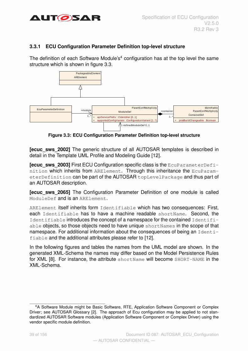
The definition of each Software Module’s4 configuration has at the top level the samestructure which is shown in figure 3.3.
EcuParameterDefinitionParamConfMultiplicity
ModuleDef
+ apiServicePrefix :CIdentifier [0..1]+ supportedConfigVariant :ConfigurationVariant [1..*]
IdentifiableParamConfMultipl icity
ContainerDef
+ postBuildChangeable :Boolean
PackageableElement
ARElement
+container
1..*
+refinedModuleDef 0..1
+module
1..*
Figure 3.3: ECU Configuration Parameter Definition top-level structure
[ecuc_sws_2002] The generic structure of all AUTOSAR templates is described indetail in the Template UML Profile and Modeling Guide [12].
[ecuc_sws_2003] First ECU Configuration specific class is the EcuParameterDefi-nition which inherits from ARElement. Through this inheritance the EcuParam-eterDefinition can be part of the AUTOSAR topLevelPackage and thus part ofan AUTOSAR description.
[ecuc_sws_2065] The Configuration Parameter Definition of one module is calledModuleDef and is an ARElement.
ARElement itself inherits form Identifiable which has two consequences: First,each Identifiable has to have a machine readable shortName. Second, theIdentifiable introduces the concept of a namespace for the contained Identifi-able objects, so those objects need to have unique shortNames in the scope of thatnamespace. For additional information about the consequences of being an Identi-fiable and the additional attributes please refer to [12].
In the following figures and tables the names from the UML model are shown. In thegenerated XML-Schema the names may differ based on the Model Persistence Rulesfor XML [8]. For instance, the attribute shortName will become SHORT-NAME in theXML-Schema.
4A Software Module might be Basic Software, RTE, Application Software Component or ComplexDriver; see AUTOSAR Glossary [2]. The approach of Ecu configuration may be applied to not stan-dardized AUTOSAR Software modules (Application Software Component or Complex Driver) using thevendor specific module definition.
39 of 156— AUTOSAR CONFIDENTIAL —
Document ID 087: AUTOSAR_ECU_Configuration

Specification of ECU ConfigurationV2.5.0
R3.2 Rev 3
Class Identifiable (abstract)Package M2::AUTOSARTemplates::GenericStructure::Infrastructure::IdentifiableNote Instances of this class can be referred to by their identifier (while adhering to
namespace borders).Base ARObjectAttribute Datatype Mul. Kind NoteshortName Identifier 1 attr Use <shortName> to generate a short name for
the context element, which enables it to be ** .
Tags: xml.enforceMinMultiplicity=true;xml.sequenceOffset=-100
longName MlData4 0..1 aggr Use <longName> to create a comprehensivename for the context element.
Tags: xml.sequenceOffset=-90desc MlData2 0..1 aggr <desc> represents a general but brief description
of the object in question.
Tags: xml.sequenceOffset=-60category String 0..1 attr This element assigns a category to the parent
element. The category can be used by a semanticchecker in post-processes to ensure that theparent object is defined correctly i.e. has the rightnumber of elements for example.
Tags: xml.sequenceOffset=-50adminData AdminData 0..1 aggr <adminData> can be used to set administrative
information for an element. This administrationinformation is to be treated as metadata such asrevision id or state of the file. There are basicallyfour kinds of metadata
• The language and/or used laguages.
• Revision information covering e.g. revisionnumber, state, release date, changes. Notethat this information can be given in generalas well as related to a particular company.
• Document metadata specific for a company
• Formatting controls that can affect layoutsfor example.
• Revision information for the element.
Tags: xml.sequenceOffset=-40
40 of 156— AUTOSAR CONFIDENTIAL —
Document ID 087: AUTOSAR_ECU_Configuration

Specification of ECU ConfigurationV2.5.0
R3.2 Rev 3
Attribute Datatype Mul. Kind Noteintroduction
DocumentationBlock
0..1 aggr This represents more information about how theobject in question is built or is used. Therefore it isa DocumentationBlock.
In this AUTOSAR Version it is intended to refer toexternal objexts which are not processed byAUTOSAR-tools.
Tags: xml.sequenceOffset=-30uuid String 1 attr The purpose of this attribute is to provide a
globally unique identifier for an instance of ametaclass. The values of this attribute should beglobally unique strings prefixed by the type ofidentifier. For example, to include a DCE UUID asdefined by The Open Group, the UUID would bepreceded by "DCE:". The values of this attributemay be used to support merging of differentAUTOSAR models. The form of the UUID(Universally Unique Identifier) is taken from astandard defined by the Open Group (was OpenSoftware Foundation). This standard is widelyused, including by Microsoft for COM (GUIDs) andby many companies for DCE, which is based onCORBA. The method for generating these 128-bitIDs is published in the standard and theeffectiveness and uniqueness of the IDs is not inpractice disputed. If the id namespace is omitted,DCE is assumed. An example is"DCE:2fac1234-31f8-11b4-a222-08002b34c003".
Tags: xml.attribute=true
Table 3.1: Identifiable
[ecuc_sws_2004] The usage-case of the EcuParameterDefinition class is to col-lect all references to individual module configuration definitions of the AUTOSAR ECUConfiguration. Therefore the EcuParameterDefinition defines a reference rela-tionship to the definition of several Software Modules in the module attribute.
41 of 156— AUTOSAR CONFIDENTIAL —
Document ID 087: AUTOSAR_ECU_Configuration
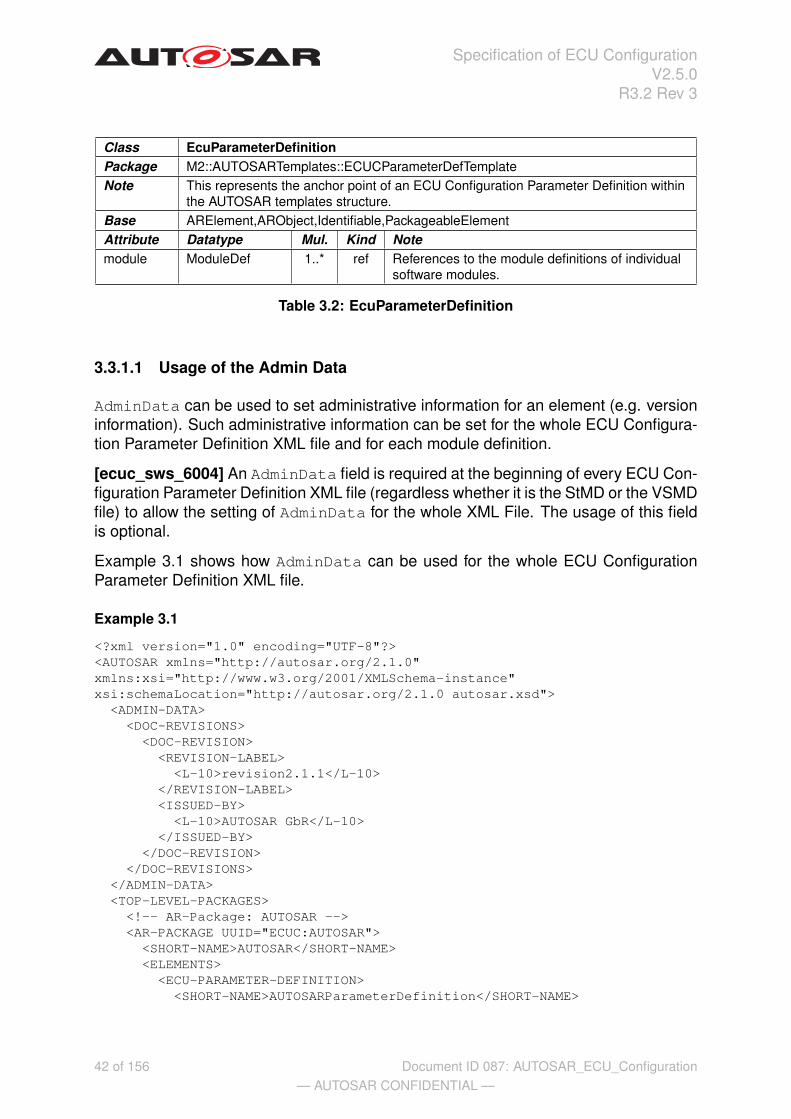
Specification of ECU ConfigurationV2.5.0
R3.2 Rev 3
Class EcuParameterDefinitionPackage M2::AUTOSARTemplates::ECUCParameterDefTemplateNote This represents the anchor point of an ECU Configuration Parameter Definition within
the AUTOSAR templates structure.Base ARElement,ARObject,Identifiable,PackageableElementAttribute Datatype Mul. Kind Notemodule ModuleDef 1..* ref References to the module definitions of individual
software modules.
Table 3.2: EcuParameterDefinition
3.3.1.1 Usage of the Admin Data
AdminData can be used to set administrative information for an element (e.g. versioninformation). Such administrative information can be set for the whole ECU Configura-tion Parameter Definition XML file and for each module definition.
[ecuc_sws_6004] An AdminData field is required at the beginning of every ECU Con-figuration Parameter Definition XML file (regardless whether it is the StMD or the VSMDfile) to allow the setting of AdminData for the whole XML File. The usage of this fieldis optional.
Example 3.1 shows how AdminData can be used for the whole ECU ConfigurationParameter Definition XML file.
Example 3.1
<?xml version="1.0" encoding="UTF-8"?><AUTOSAR xmlns="http://autosar.org/2.1.0"xmlns:xsi="http://www.w3.org/2001/XMLSchema-instance"xsi:schemaLocation="http://autosar.org/2.1.0 autosar.xsd">
<ADMIN-DATA><DOC-REVISIONS>
<DOC-REVISION><REVISION-LABEL><L-10>revision2.1.1</L-10>
</REVISION-LABEL><ISSUED-BY>
<L-10>AUTOSAR GbR</L-10></ISSUED-BY>
</DOC-REVISION></DOC-REVISIONS>
</ADMIN-DATA><TOP-LEVEL-PACKAGES>
<!-- AR-Package: AUTOSAR --><AR-PACKAGE UUID="ECUC:AUTOSAR">
<SHORT-NAME>AUTOSAR</SHORT-NAME><ELEMENTS>
<ECU-PARAMETER-DEFINITION><SHORT-NAME>AUTOSARParameterDefinition</SHORT-NAME>
42 of 156— AUTOSAR CONFIDENTIAL —
Document ID 087: AUTOSAR_ECU_Configuration

Specification of ECU ConfigurationV2.5.0
R3.2 Rev 3
[ecuc_sws_6005] For each module definition there needs to be provided which revi-sion the StMD is. For the VSMD the AUTOSAR release version and the vendor’s ownversion information must be provided. The usage of AdminData on ModuleDef ismandatory.
Example 3.2 shows that there are possibilities to specify several elements for the Ad-minData. The initial one would be provided by AUTOSAR, the additional one is thevendor’s information which is based on the AUTOSAR one.
Example 3.2
...<MODULE-DEF UUID="ECUC:c03229fe-4dca-445e-a47c-1ae11e6c1832">
<SHORT-NAME>Adc</SHORT-NAME><DESC>
<L-2 L="EN">Configuration of the Adc(Analog Digital Conversion) module.</L-2>
</DESC><ADMIN-DATA>
<DOC-REVISIONS><DOC-REVISION>
<REVISION-LABEL><L-10>revision2.1.1</L-10>
</REVISION-LABEL><ISSUED-BY>
<L-10>AUTOSAR GbR</L-10></ISSUED-BY><DATE>
<L-10>09.05.2007</L-10></DATE>
</DOC-REVISION><DOC-REVISION>
<REVISION-LABEL><L-10>version15.3</L-10>
</REVISION-LABEL><!--predecessor --><REVISION-LABEL-P-1>revision2.1.1</REVISION-LABEL-P-1><ISSUED-BY>
<L-10>VendorX</L-10></ISSUED-BY><DATE>
<L-10>19.05.2007</L-10></DATE>
</DOC-REVISION></DOC-REVISIONS>
</ADMIN-DATA><LOWER-MULTIPLICITY>0</LOWER-MULTIPLICITY><UPPER-MULTIPLICITY>1</UPPER-MULTIPLICITY><CONTAINERS>
...
43 of 156— AUTOSAR CONFIDENTIAL —
Document ID 087: AUTOSAR_ECU_Configuration
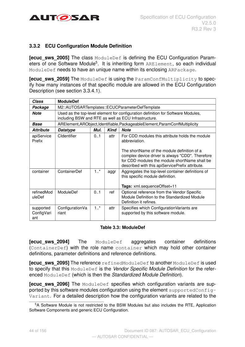
Specification of ECU ConfigurationV2.5.0
R3.2 Rev 3
3.3.2 ECU Configuration Module Definition
[ecuc_sws_2005] The class ModuleDef is defining the ECU Configuration Param-eters of one Software Module5. It is inheriting form ARElement, so each individualModuleDef needs to have an unique name within its enclosing ARPackage.
[ecuc_sws_2059] The ModuleDef is using the ParamConfMultiplicity to spec-ify how many instances of that specific module are allowed in the ECU ConfigurationDescription (see section 3.3.4.1).
Class ModuleDefPackage M2::AUTOSARTemplates::ECUCParameterDefTemplateNote Used as the top-level element for configuration definition for Software Modules,
including BSW and RTE as well as ECU Infrastructure.Base ARElement,ARObject,Identifiable,PackageableElement,ParamConfMultiplicityAttribute Datatype Mul. Kind NoteapiServicePrefix
CIdentifier 0..1 attr For CDD modules this attribute holds the moduleabbreviation.
The shortName of the module definition of acomplex device driver is always "CDD". Thereforefor CDD modules the module shortName shall bedescribed with this apiServicePrefix attribute.
container ContainerDef 1..* aggr Aggregates the top-level container definitions ofthis specific module definition.
Tags: xml.sequenceOffset=11refinedModuleDef
ModuleDef 0..1 ref Optional reference from the Vendor SpecificModule Definition to the Standardized ModuleDefinition it refines.
supportedConfigVariant
ConfigurationVariant
1..* attr Specifies which ConfigurationVariants aresupported by this software module.
Table 3.3: ModuleDef
[ecuc_sws_2094] The ModuleDef aggregates container definitions(ContainerDef) with the role name container which may hold other containerdefinitions, parameter definitions and reference definitions.
[ecuc_sws_2095] The reference refinedModuleDef to another ModuleDef is usedto specify that this ModuleDef is the Vendor Specific Module Definition for the refer-enced ModuleDef (which is then the Standardized Module Definition).
[ecuc_sws_2096] The ModuleDef specifies which configuration variants are sup-ported by this software modules configuration using the element supportedConfig-Variant. For a detailed description how the configuration variants are related to the
5A Software Module is not restricted to the BSW Modules but also includes the RTE, ApplicationSoftware Components and generic ECU Configuration.
44 of 156— AUTOSAR CONFIDENTIAL —
Document ID 087: AUTOSAR_ECU_Configuration

Specification of ECU ConfigurationV2.5.0
R3.2 Rev 3
configuration classes please refer to section 3.3.4.2.2. For each configuration variantthat is supported one entry shall be provided.
In figure 3.4 an actual example of the top-level structure is provided and in the exam-ple 3.3 the corresponding ECU Configuration Parameter Definition XML file extract isshown. In the example XML also the overall XML structure of AUTOSAR descriptionsis shown.
AUTOSARParameterDefinition :EcuParameterDefinition
Rte :ModuleDef
upperMultiplicity = 1lowerMultiplicity = 0
RteGeneration :ParamConfContainerDef
upperMultipl icity = 1lowerMultipl icity = 1
+container+module
Figure 3.4: ECU Configuration Definition example
Example 3.3
<AUTOSAR><TOP-LEVEL-PACKAGES>
<AR-PACKAGE><SHORT-NAME>AUTOSAR</SHORT-NAME><ELEMENTS>
<ECU-PARAMETER-DEFINITION><SHORT-NAME>ParamDef</SHORT-NAME><MODULE-REFS>
<MODULE-REF DEST="MODULE-DEF">/AUTOSAR/Rte</MODULE-REF><!-- Further references to module definitions -->
</MODULE-REFS></ECU-PARAMETER-DEFINITION><MODULE-DEF>
<SHORT-NAME>Rte</SHORT-NAME><LOWER-MULTIPLICITY>0</LOWER-MULTIPLICITY><UPPER-MULTIPLICITY>1</UPPER-MULTIPLICITY><SUPPORTED-CONFIG-VARIANTS>
<SUPPORTED-CONFIG-VARIANT>VARIANT-PRE-COMPILE</SUPPORTED-CONFIG-VARIANT></SUPPORTED-CONFIG-VARIANTS><CONTAINERS>
<!-- ... --></CONTAINERS>
</MODULE-DEF></ELEMENTS>
</AR-PACKAGE></TOP-LEVEL-PACKAGES>
</AUTOSAR>
In the next sections the structure of containers, individual parameters and referencesis introduced.
3.3.3 Container Definition
[ecuc_sws_2006] The container definition is used to group other parameter containerdefinitions, parameter definitions and reference definitions.
45 of 156— AUTOSAR CONFIDENTIAL —
Document ID 087: AUTOSAR_ECU_Configuration

Specification of ECU ConfigurationV2.5.0
R3.2 Rev 3
There are two specializations of a container definition. The abstract class Contain-erDef is used to gather the common features (see figure 3.5).
ParamConfContainerDef
+ multipleConfigurationContainer :Boolean
IdentifiableParamConfMultipl icity
ContainerDef
+ postBuildChangeable :Boolean
ChoiceContainerDef
ConfigParameter
+ symbolicNameValue :Boolean
ConfigReference
IdentifiableParamConfMultiplicity
CommonConfigurationAttributes
+ origin :String
+choice
*
+reference
*
+parameter
*
+subContainer
*
Figure 3.5: Class diagram for parameter container definition
Class ContainerDef (abstract)Package M2::AUTOSARTemplates::ECUCParameterDefTemplateNote Base class used to gather common attributes of configuration container definitions.Base ARObject,Identifiable,ParamConfMultiplicityAttribute Datatype Mul. Kind NotepostBuildChangeable
Boolean 1 attr Specifies if the number of instances of thiscontainer may be changed post-build time. Thisparameter may only be set to true if all of thefollowing conditions hold:
• the container’s upperMultiplicity >lowerMultiplicity
• all parameters within the container andsubContainers are post-build timechangeable.
If any of the aggregated parameters is eitherpre-compile time or link time this attribute isignored and may be omitted.
Table 3.4: ContainerDef
[ecuc_sws_2043] Each ContainerDef is an Identifiable.
[ecuc_sws_2044] Each ContainerDef also has the features of ParamConfMulti-plicity which enables to specify for each ContainerDef how often it is allowed tooccur in the ECU Configuration Description later on (see section 3.3.4.1).
[ecuc_sws_2064] The attribute postBuildChangeable specifies if the number ofcontainers can be changed PostBuild time in the ECU Configuration Description.
[ecuc_sws_2007] A ParamConfContainerDef is the main container class definitionand can contain other containers, configuration parameters and references.
46 of 156— AUTOSAR CONFIDENTIAL —
Document ID 087: AUTOSAR_ECU_Configuration

Specification of ECU ConfigurationV2.5.0
R3.2 Rev 3
Class ParamConfContainerDefPackage M2::AUTOSARTemplates::ECUCParameterDefTemplateNote Used to define configuration containers that can hierarchically contain other
containers and/or parameter definitions.Base ARObject,ContainerDef,Identifiable,ParamConfMultiplicityAttribute Datatype Mul. Kind NotemultipleConfigurationContainer
Boolean 1 attr Specifies whether this container is used to definemultiple configuration sets. Only one container inthe whole ModuleDef shall have this enabled.
parameter ConfigParameter
* aggr The parameters defined within theParamConfContainerDef.
reference ConfigReference
* aggr The references defined within theParamConfContainerDef.
subContainer
ContainerDef * aggr The containers defined within theParamConfContainerDef.
Table 3.5: ParamConfContainerDef
One example of a ContainerDef and its embedding in the ECU Configuration Pa-rameter Definition is shown in figure 3.6. One ModuleDef Rte is specified being partof the EcuParameterDefinition. Two containers of type ParameterConfParam-Def are specified as part of the module definition.
When specifying the containment relationship between the ModuleDef and containersthe role name container is used. When specifying the containment relationshipbetween two containers an aggregation with the role name subContainer at thecontained container is used.
AUTOSARParameterDefinition :EcuParameterDefinition
Rte :ModuleDef
upperMultiplicity = 1lowerMultiplicity = 0
RteGeneration :ParamConfContainerDef
upperMultiplicity = 1lowerMultiplicity = 1
SwComponentInstance :ParamConfContainerDef
upperMultiplicity = *lowerMultiplicity = 1
+container+module
+container
Figure 3.6: Example of an object diagram for container definition
In the XML outtake in example 3.4 only the relevant part from figure 3.6 is shown, notincluding the EcuParameterDefinition.
47 of 156— AUTOSAR CONFIDENTIAL —
Document ID 087: AUTOSAR_ECU_Configuration

Specification of ECU ConfigurationV2.5.0
R3.2 Rev 3
Example 3.4
...<MODULE-DEF>
<SHORT-NAME>Rte</SHORT-NAME><LOWER-MULTIPLICITY>0</LOWER-MULTIPLICITY><UPPER-MULTIPLICITY>1</UPPER-MULTIPLICITY><CONTAINERS>
<PARAM-CONF-CONTAINER-DEF><SHORT-NAME>RteGeneration</SHORT-NAME><LOWER-MULTIPLICITY>1</LOWER-MULTIPLICITY><UPPER-MULTIPLICITY>1</UPPER-MULTIPLICITY>
<MULTIPLE-CONFIGURATION-CONTAINER>false</MULTIPLE-CONFIGURATION-CONTAINER></PARAM-CONF-CONTAINER-DEF><PARAM-CONF-CONTAINER-DEF>
<SHORT-NAME>SwComponentInstance</SHORT-NAME><LOWER-MULTIPLICITY>1</LOWER-MULTIPLICITY><UPPER-MULTIPLICITY>*</UPPER-MULTIPLICITY>
<MULTIPLE-CONFIGURATION-CONTAINER>false</MULTIPLE-CONFIGURATION-CONTAINER></PARAM-CONF-CONTAINER-DEF>
</CONTAINERS></MODULE-DEF>
...
3.3.3.1 Choice Container Definition
[ecuc_sws_2011] The ChoiceContainerDef can be used to specify that certaincontainers might occur exclusively in the ECU Configuration Description. In the ECUConfiguration Parameter Definition the potential containers are specified as part ofthe ChoiceContainerDef and the constraint is that in the actual ECU ConfigurationDescription only some of those specified containers will actually be present.
Class ChoiceContainerDefPackage M2::AUTOSARTemplates::ECUCParameterDefTemplateNote Used to define configuration containers that provide a choice between several
ParamConfContainerDef. But in the actual ECU Configuration Description only oneinstance from the choice list will be present (depending on the multiplicites given).
Base ARObject,ContainerDef,Identifiable,ParamConfMultiplicityAttribute Datatype Mul. Kind Notechoice ParamConfCont
ainerDef* aggr The choices available in a ChoiceContainerDef.
Table 3.6: ChoiceContainerDef
[ecuc_sws_2067] The multiplicity of the to be chosen containers shall always be 0..1,indicating that each time a choice is performed you can only choose one of these to bechosen containers at a time.
48 of 156— AUTOSAR CONFIDENTIAL —
Document ID 087: AUTOSAR_ECU_Configuration

Specification of ECU ConfigurationV2.5.0
R3.2 Rev 3
[ecuc_sws_2012] The upperMultiplicity of the ChoiceContainerDef doesspecify how often the choice can be performed. If the upperMultiplicity of theChoiceContainerDef > 1, the SUM of the chosen containers has to be consid-ered.
[ecuc_sws_2068] Each time a choice can be performed, the user is free to choosefrom the available to be chosen containers. The Configuration Editor needs to collectall the chosen containers of the ECU Configuration Description and make sure the sumis not greater than the upperMultiplicity of the ChoiceContainerDef.
This limits the usage of ChoiceContainerDef: Each to be chosen container can onlybe defined as a choice for one ChoiceContainerDef in the same parent container(otherwise it is not possible to distinguish from which ChoiceContainerDef a to bechosen container is from. And a container can not be a to be chosen container as wellas a plain subContainer in the same parent container (otherwise it is not possible todistinguish between the plain container and the ChoiceContainerDef choice).
An example of the usage of a ChoiceContainerDef is shown in figure 3.7 and thecorresponding XML definition is shown in example 3.5.
OsAlarmAction :ChoiceContainerDef
OsAlarmActivateTask :ParamConfContainerDef
upperMultiplicity = 1lowerMultiplicity = 0
OsAlarmSetEvent :ParamConfContainerDef
upperMultipl icity = 1lowerMultipl icity = 0
OsAlarmCallback :ParamConfContainerDef
upperMultipl icity = 1lowerMultipl icity = 0
OsAlarmIncrementCounter :ParamConfContainerDef
upperMultiplicity = 1lowerMultiplicity = 0
OsAlarm :ParamConfContainerDef
upperMultipl icity = *lowerMultipl icity = 0
+subContainer
+choice +choice+choice +choice
Figure 3.7: Example of an object diagram for choice container definition
The ChoiceContainerDef OSAlarmAction is defined to be able to hold one ofthe four given containers later in the ECU Configuration Description. Since the up-perMultiplicity of OsAlarmAction = 1 there can only be one choice taken.
49 of 156— AUTOSAR CONFIDENTIAL —
Document ID 087: AUTOSAR_ECU_Configuration

Specification of ECU ConfigurationV2.5.0
R3.2 Rev 3
Example 3.5
...<PARAM-CONF-CONTAINER-DEF>
<SHORT-NAME>OsAlarm</SHORT-NAME><LOWER-MULTIPLICITY>0</LOWER-MULTIPLICITY><UPPER-MULTIPLICITY>*</UPPER-MULTIPLICITY><SUB-CONTAINERS>
<CHOICE-CONTAINER-DEF><SHORT-NAME>OsAlarmAction</SHORT-NAME><LOWER-MULTIPLICITY>1</LOWER-MULTIPLICITY><UPPER-MULTIPLICITY>1</UPPER-MULTIPLICITY><CHOICES>
<PARAM-CONF-CONTAINER-DEF><SHORT-NAME>OsAlarmActivateTask</SHORT-NAME><!-- ... -->
</PARAM-CONF-CONTAINER-DEF><PARAM-CONF-CONTAINER-DEF>
<SHORT-NAME>OsAlarmSetEvent</SHORT-NAME><!-- ... -->
</PARAM-CONF-CONTAINER-DEF><PARAM-CONF-CONTAINER-DEF>
<SHORT-NAME>OsAlarmCallback</SHORT-NAME><!-- ... -->
</PARAM-CONF-CONTAINER-DEF><PARAM-CONF-CONTAINER-DEF>
<SHORT-NAME>OsAlarmIncrementCounter</SHORT-NAME><!-- ... -->
</PARAM-CONF-CONTAINER-DEF></CHOICES>
</CHOICE-CONTAINER-DEF></SUB-CONTAINERS>
</PARAM-CONF-CONTAINER-DEF>...
The containers from the example, which the choice is from, will of course have to bespecified in more detail in an actual definition file.
3.3.3.2 Multiple Configuration Set Definition
To allow the description of several Ecu Configuration Sets a ModuleDef may containone ParamConfContainerDef which is specified to be the multipleConfigura-tionContainer.
[ecuc_sws_2091] A ParamConfContainerDef does specify whether the definedcontainer is the multipleConfigurationContainer. Each ModuleDef shall con-tain exactly one such container if it supports multiple configuration sets.
If a ParamConfContainerDef is specified to be the multipleConfiguration-SetContainer there can be several Container descriptions of this container in the
50 of 156— AUTOSAR CONFIDENTIAL —
Document ID 087: AUTOSAR_ECU_Configuration

Specification of ECU ConfigurationV2.5.0
R3.2 Rev 3
Ecu Configuration Description for PostBuild configurations6. The shortName of themultipleConfigurationContainer does define the name of the configuration set(see also section 3.4.7 for details on the Ecu Configuration Description).
Adc :ModuleDef
upperMultiplicity = 1lowerMultiplicity = 0
AdcHwUnit :ParamConfContainerDef
upperMultipl icity = *lowerMultipl icity = 1
AdcGroup :ParamConfContainerDef
upperMultipl icity = *lowerMultipl icity = 1
AdcConfigSet :ParamConfContainerDef
multipleConfigurationContainer = true
AdcHwUnitId :IntegerParamDef
symbolicNameValue = true
+subContainer
+subContainer
+parameter
+container
Figure 3.8: Example of an object diagram for multiple configuration container definition
Example 3.6
...<MODULE-DEF>
<SHORT-NAME>Adc</SHORT-NAME><LOWER-MULTIPLICITY>0</LOWER-MULTIPLICITY><UPPER-MULTIPLICITY>1</UPPER-MULTIPLICITY><CONTAINERS>
<PARAM-CONF-CONTAINER-DEF><SHORT-NAME>AdcConfigSet</SHORT-NAME><LOWER-MULTIPLICITY>1</LOWER-MULTIPLICITY><UPPER-MULTIPLICITY>1</UPPER-MULTIPLICITY>
<MULTIPLE-CONFIGURATION-CONTAINER>true</MULTIPLE-CONFIGURATION-CONTAINER><SUB-CONTAINERS>
<PARAM-CONF-CONTAINER-DEF><SHORT-NAME>AdcHwUnit</SHORT-NAME>
<MULTIPLE-CONFIGURATION-CONTAINER>false</MULTIPLE-CONFIGURATION-CONTAINER><PARAMETERS>
<INTEGER-PARAM-DEF><SHORT-NAME>AdcHwUnitIt</SHORT-NAME>
</INTEGER-PARAM-DEF></PARAMETERS><SUB-CONTAINERS>
<PARAM-CONF-CONTAINER-DEF><SHORT-NAME>AdcGroup</SHORT-NAME>
<MULTIPLE-CONFIGURATION-CONTAINER>false</MULTIPLE-CONFIGURATION-CONTAINER><!-- ... -->
</PARAM-CONF-CONTAINER-DEF></SUB-CONTAINERS>
</PARAM-CONF-CONTAINER-DEF></SUB-CONTAINERS>
</PARAM-CONF-CONTAINER-DEF></CONTAINERS>
</MODULE-DEF>...
For the ECU Configuration Description of this example please refer to section 3.4.7.6In case of PreComiple and LinkTime configuration variants the features of the multipleConfig-
urationContainer are not used.
51 of 156— AUTOSAR CONFIDENTIAL —
Document ID 087: AUTOSAR_ECU_Configuration
Specification of ECU ConfigurationV2.5.0
R3.2 Rev 3
3.3.4 Common Configuration Elements
Configuration Parameters and references have some common attributes which are de-scribed in this section.
3.3.4.1 Parameter Configuration Multiplicity
[ecuc_sws_2008] To be able to specify how often a specific configuration element(container, parameter or reference) may occur in the ECU Configuration Description theclass ParamConfMultiplicity is introduced. With the two attributes lowerMul-tiplicity and upperMultiplicity the minimum and maximum occurrence of theconfiguration element is specified.
[ecuc_sws_2009] When there is no multiplicity specified the default is exactly ’1’meaning the element is mandatory in the ECU Configuration Description and has tooccur exactly once. To express an optional element the lowerMultiplicity has tobe set to ’0’. To express unlimited number of occurrences of this element the upper-Multiplicity is to be set to ’*’.
Configuration Parameter and Reference definitions with an upperMultiplicity>1have to be considered with care, since it is not possible to reference to individual pa-rameters. So such multiple occurrences of a parameter in the description will just bemere collections, it is neither guaranteed that the order will be preserved nor that thatindividual elements do have a special semantics.
[ecuc_sws_2010] In the specification object diagrams the multiplicity attributes maybe omitted if both values are equal to the default value of ’1’. Otherwise both attributesare shown.
52 of 156— AUTOSAR CONFIDENTIAL —
Document ID 087: AUTOSAR_ECU_Configuration

Specification of ECU ConfigurationV2.5.0
R3.2 Rev 3
Class ParamConfMultiplicity (abstract)Package M2::AUTOSARTemplates::ECUCParameterDefTemplateNote Common class used to express multiplicities in the definition of configuration
parameters, references and containers. If not stated otherwise the default multiplicityis exactly one mandatory occurrence of the specified element.
Base ARObjectAttribute Datatype Mul. Kind NotelowerMultiplicity
String 1 attr The lower multiplicity of the specified element. 0:optional 1: at least one occurence n: at least noccurrences
upperMultiplicity
String 1 attr The upper multiplicity of the specified element. 1:at most one occurrence m: at most moccurrencesarbitrary number of occurrences
Table 3.7: ParamConfMultiplicity
For examples please refer to figure 3.6 and example 3.4
3.3.4.2 Common Configuration Attributes
Several attributes are available on both, parameters and references. These commonattributes are shown in figure 3.9.
ECUCParameterDefTemplate::ConfigParameter
+ symbolicNameValue :Boolean
ContainerDef
ECUCParameterDefTemplate::ParamConfContainerDef
+ multipleConfigurationContainer :Boolean
«enumeration»ECUCParameterDefTemplate::
ConfigurationClass
PublishedInformation PreCompile Link PostBuild
Identifiable
ECUCParameterDefTemplate::CommonConfigurationAttributes
+ origin :String
ECUCParameterDefTemplate::ConfigReference
ECUCParameterDefTemplate::ParamConfMultiplicity
+ lowerMultipl icity :String+ upperMultipl icity :String
ECUCParameterDefTemplate::ConfigurationClassAffection
+ affectionKind :ConfigurationAffection
«enumeration»ECUCParameterDefTemplate::
ConfigurationAffection
NOAffect PCAffectsLT PCAffectsPB PCAffectsLTAndPB LTAffectsPB
ECUCParameterDefTemplate::ImplementationConfigClass
+ configClass :ConfigurationClass+ configVariant :ConfigurationVariant
«enumeration»ECUCParameterDefTemplate::
ConfigurationVariant
VariantPreCompile VariantLinkTime VariantPostBuild VariantPostBuildLoadable VariantPostBuildSelectable
+reference
*
+parameter
*
+configurationClassAffection
0..1+affected
0..*
+implementationConfigClass 1..*
Figure 3.9: Common Attributes for parameters and references
53 of 156— AUTOSAR CONFIDENTIAL —
Document ID 087: AUTOSAR_ECU_Configuration
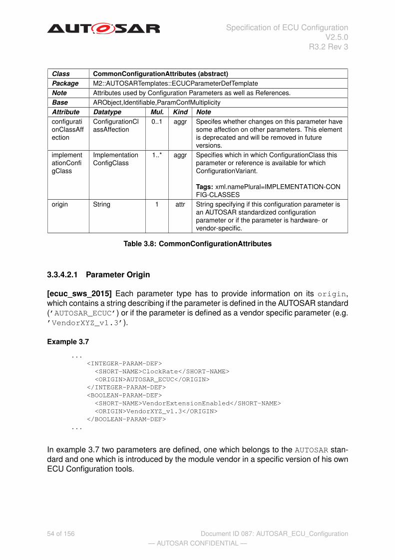
Specification of ECU ConfigurationV2.5.0
R3.2 Rev 3
Class CommonConfigurationAttributes (abstract)Package M2::AUTOSARTemplates::ECUCParameterDefTemplateNote Attributes used by Configuration Parameters as well as References.Base ARObject,Identifiable,ParamConfMultiplicityAttribute Datatype Mul. Kind NoteconfigurationClassAffection
ConfigurationClassAffection
0..1 aggr Specifes whether changes on this parameter havesome affection on other parameters. This elementis deprecated and will be removed in futureversions.
implementationConfigClass
ImplementationConfigClass
1..* aggr Specifies which in which ConfigurationClass thisparameter or reference is available for whichConfigurationVariant.
Tags: xml.namePlural=IMPLEMENTATION-CONFIG-CLASSES
origin String 1 attr String specifying if this configuration parameter isan AUTOSAR standardized configurationparameter or if the parameter is hardware- orvendor-specific.
Table 3.8: CommonConfigurationAttributes
3.3.4.2.1 Parameter Origin
[ecuc_sws_2015] Each parameter type has to provide information on its origin,which contains a string describing if the parameter is defined in the AUTOSAR standard(’AUTOSAR_ECUC’) or if the parameter is defined as a vendor specific parameter (e.g.’VendorXYZ_v1.3’).
Example 3.7
...<INTEGER-PARAM-DEF>
<SHORT-NAME>ClockRate</SHORT-NAME><ORIGIN>AUTOSAR_ECUC</ORIGIN>
</INTEGER-PARAM-DEF><BOOLEAN-PARAM-DEF>
<SHORT-NAME>VendorExtensionEnabled</SHORT-NAME><ORIGIN>VendorXYZ_v1.3</ORIGIN>
</BOOLEAN-PARAM-DEF>...
In example 3.7 two parameters are defined, one which belongs to the AUTOSAR stan-dard and one which is introduced by the module vendor in a specific version of his ownECU Configuration tools.
54 of 156— AUTOSAR CONFIDENTIAL —
Document ID 087: AUTOSAR_ECU_Configuration
Specification of ECU ConfigurationV2.5.0
R3.2 Rev 3
3.3.4.2.2 Implementation Configuration Classes
[ecuc_sws_2016] The attribute implementationConfigClass provides informa-tion what kind of configuration class this parameter shall be implemented for each ofthe supported configuration variants. The different configuration classes defined withinAUTOSAR are7:
• [ecuc_sws_2070] PublishedInformation
• [ecuc_sws_2017] PreCompile
• [ecuc_sws_2018] Link
• [ecuc_sws_2019] PostBuild8
The element PublishedInformation is used to specify the fact that certain infor-mation is fixed even before the pre-compile stage.
[ecuc_sws_2071] If PublishedInformation is selected as configuration class ithas to be the for all configuration variants.
[ecuc_sws_2022] The configuration parameter definition of the BSW has the possibil-ity to define up to three configuration variants how actual configuration parameters canbe implemented. So the implementor of the module does not have complete freedomhow the configuration classes are chosen for each individual configuration parameterbut needs to select one of the specified variants.
[ecuc_sws_2097] The supported configuration variants in the StMD are9:
• [ecuc_sws_2098] VariantPreCompile
• [ecuc_sws_2099] VariantLinkTime
• [ecuc_sws_2100] VariantPostBuild
[ecuc_sws_6049] The supported configuration variants in the VSMD are:
• [ecuc_sws_6050] VariantPreCompile
• [ecuc_sws_6051] VariantLinkTime
• [ecuc_sws_6052] VariantPostBuildLoadable
• [ecuc_sws_6053] VariantPostBuildSelectable
The mapping of the ConfigurationVariant to the ConfigurationClass is doneusing the ImplementationConfigClass:
7In the XML-Schema the values are represented as PUBLISHED-INFORMATION, PRE-COMPILE,LINK, POST-BUILD.
8The configuration classes PostBuildLoadable and PostBuildSelectable are no longer re-quired for the standardized ECU Configuration Parameter Definition because the difference betweenthese two configuration classes is only relevant for the memory mapping of the configuration data duringlinking. In the VSMD the distinction is still made as described in chapter 5.1.
9In the XML-Schema the values are represented as VARIANT-PRE-COMPILE, VARIANT-LINK-TIME, VARIANT-POST-BUILD.
55 of 156— AUTOSAR CONFIDENTIAL —
Document ID 087: AUTOSAR_ECU_Configuration
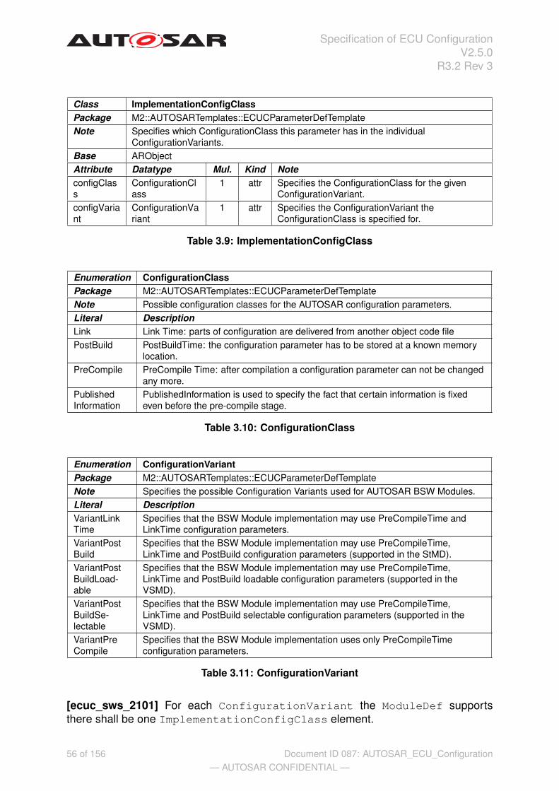
Specification of ECU ConfigurationV2.5.0
R3.2 Rev 3
Class ImplementationConfigClassPackage M2::AUTOSARTemplates::ECUCParameterDefTemplateNote Specifies which ConfigurationClass this parameter has in the individual
ConfigurationVariants.Base ARObjectAttribute Datatype Mul. Kind NoteconfigClass
ConfigurationClass
1 attr Specifies the ConfigurationClass for the givenConfigurationVariant.
configVariant
ConfigurationVariant
1 attr Specifies the ConfigurationVariant theConfigurationClass is specified for.
Table 3.9: ImplementationConfigClass
Enumeration ConfigurationClassPackage M2::AUTOSARTemplates::ECUCParameterDefTemplateNote Possible configuration classes for the AUTOSAR configuration parameters.Literal DescriptionLink Link Time: parts of configuration are delivered from another object code filePostBuild PostBuildTime: the configuration parameter has to be stored at a known memory
location.PreCompile PreCompile Time: after compilation a configuration parameter can not be changed
any more.PublishedInformation
PublishedInformation is used to specify the fact that certain information is fixedeven before the pre-compile stage.
Table 3.10: ConfigurationClass
Enumeration ConfigurationVariantPackage M2::AUTOSARTemplates::ECUCParameterDefTemplateNote Specifies the possible Configuration Variants used for AUTOSAR BSW Modules.Literal DescriptionVariantLinkTime
Specifies that the BSW Module implementation may use PreCompileTime andLinkTime configuration parameters.
VariantPostBuild
Specifies that the BSW Module implementation may use PreCompileTime,LinkTime and PostBuild configuration parameters (supported in the StMD).
VariantPostBuildLoad-able
Specifies that the BSW Module implementation may use PreCompileTime,LinkTime and PostBuild loadable configuration parameters (supported in theVSMD).
VariantPostBuildSe-lectable
Specifies that the BSW Module implementation may use PreCompileTime,LinkTime and PostBuild selectable configuration parameters (supported in theVSMD).
VariantPreCompile
Specifies that the BSW Module implementation uses only PreCompileTimeconfiguration parameters.
Table 3.11: ConfigurationVariant
[ecuc_sws_2101] For each ConfigurationVariant the ModuleDef supportsthere shall be one ImplementationConfigClass element.
56 of 156— AUTOSAR CONFIDENTIAL —
Document ID 087: AUTOSAR_ECU_Configuration
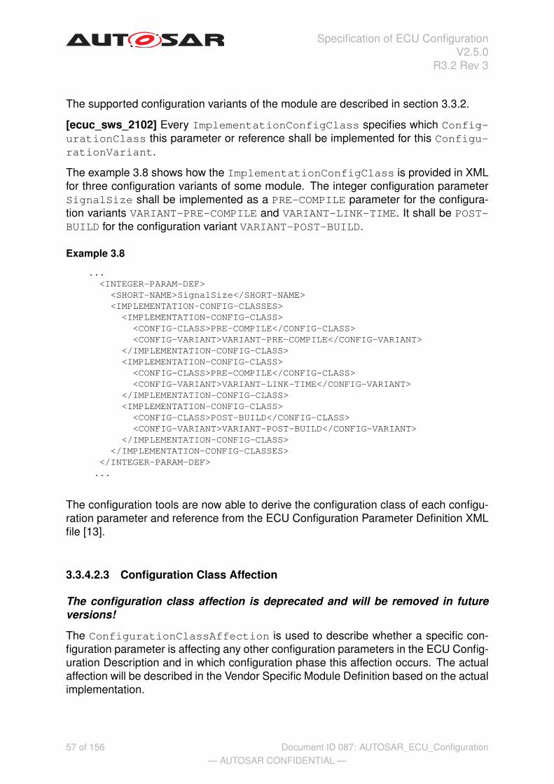
Specification of ECU ConfigurationV2.5.0
R3.2 Rev 3
The supported configuration variants of the module are described in section 3.3.2.
[ecuc_sws_2102] Every ImplementationConfigClass specifies which Config-urationClass this parameter or reference shall be implemented for this Configu-rationVariant.
The example 3.8 shows how the ImplementationConfigClass is provided in XMLfor three configuration variants of some module. The integer configuration parameterSignalSize shall be implemented as a PRE-COMPILE parameter for the configura-tion variants VARIANT-PRE-COMPILE and VARIANT-LINK-TIME. It shall be POST-BUILD for the configuration variant VARIANT-POST-BUILD.
Example 3.8
...<INTEGER-PARAM-DEF>
<SHORT-NAME>SignalSize</SHORT-NAME><IMPLEMENTATION-CONFIG-CLASSES><IMPLEMENTATION-CONFIG-CLASS>
<CONFIG-CLASS>PRE-COMPILE</CONFIG-CLASS><CONFIG-VARIANT>VARIANT-PRE-COMPILE</CONFIG-VARIANT>
</IMPLEMENTATION-CONFIG-CLASS><IMPLEMENTATION-CONFIG-CLASS>
<CONFIG-CLASS>PRE-COMPILE</CONFIG-CLASS><CONFIG-VARIANT>VARIANT-LINK-TIME</CONFIG-VARIANT>
</IMPLEMENTATION-CONFIG-CLASS><IMPLEMENTATION-CONFIG-CLASS>
<CONFIG-CLASS>POST-BUILD</CONFIG-CLASS><CONFIG-VARIANT>VARIANT-POST-BUILD</CONFIG-VARIANT>
</IMPLEMENTATION-CONFIG-CLASS></IMPLEMENTATION-CONFIG-CLASSES>
</INTEGER-PARAM-DEF>...
The configuration tools are now able to derive the configuration class of each configu-ration parameter and reference from the ECU Configuration Parameter Definition XMLfile [13].
3.3.4.2.3 Configuration Class Affection
The configuration class affection is deprecated and will be removed in futureversions!
The ConfigurationClassAffection is used to describe whether a specific con-figuration parameter is affecting any other configuration parameters in the ECU Config-uration Description and in which configuration phase this affection occurs. The actualaffection will be described in the Vendor Specific Module Definition based on the actualimplementation.
57 of 156— AUTOSAR CONFIDENTIAL —
Document ID 087: AUTOSAR_ECU_Configuration

Specification of ECU ConfigurationV2.5.0
R3.2 Rev 3
The possible values for the affectionKind of a ConfigurationClassAffectionare10:
• [ecuc_sws_2076] NOAffect
• [ecuc_sws_2077] PCAffectsLT
• [ecuc_sws_2078] PCAffectsPB
• [ecuc_sws_2079] PCAffectsLTAndPB
• [ecuc_sws_2080] LTAffectsPB
[ecuc_sws_2081] The reference affected from the ConfigurationClass-Affection to any subclass of CommonConfigurationAttributes is used to de-fine which actual parameters and references are affected.
For a detailed description of the affection mechanism refer to section 2.3.4.1.
Class ConfigurationClassAffectionPackage M2::AUTOSARTemplates::ECUCParameterDefTemplateNote Specifies in the "VendorSpecificModuleDefinition" whether changes on this parameter
do affect other parameters in a later configuration step. This element is deprecatedand will be removed in future versions.
Base ARObjectAttribute Datatype Mul. Kind Noteaffected CommonConfig
urationAttributes* ref Optional reference to parameters or references
which are affected by theConfigurationClassAffection.
affectionKind
ConfigurationAffection
1 attr Specifies which affect do changes in thisparameter have on other parameters. Thisattribute is deprecated and will be removed infuture versions.
Table 3.12: ConfigurationClassAffection
3.3.5 Parameter Definition
[ecuc_sws_2013] Parameters are defined within a ParamConfContainerDef usingan aggregation with the role name parameter at the parameter side.
[ecuc_sws_2014] The possible parameter types are specified using one of the spe-cialized classes derived from ParameterType. The ParameterType does inheritfrom Identifiable and ParamConfMultiplicity.
The available parameter types are shown in figure 3.10.10In the XML-Schema the values are represented as NO-AFFECT, PC-AFFECTS-LT, PC-AFFECTS-
PB, PC-AFFECTS-LT-AND-PB, LT-AFFECTS-PB.
58 of 156— AUTOSAR CONFIDENTIAL —
Document ID 087: AUTOSAR_ECU_Configuration

Specification of ECU ConfigurationV2.5.0
R3.2 Rev 3
IntegerParamDef
+ defaultValue :UnlimitedInteger [0..1]+ max :UnlimitedInteger [0..1]+ min :UnlimitedInteger [0..1]
BooleanParamDef
+ defaultValue :Boolean [0..1]
FloatParamDef
+ defaultValue :Float [0..1]+ max :Float [0..1]+ min :Float [0..1]
StringParamDef
+ defaultValue :String [0..1]
FunctionNameDef
EnumerationParamDef
+ defaultValue :String [0..1]
Identifiable
EnumerationLiteralDef
CommonConfigurationAttributes
ConfigParameter
+ symbolicNameValue :Boolean
ContainerDef
ParamConfContainerDef
+ multipleConfigurationContainer :Boolean
LinkerSymbolDef
+parameter
*
+literal 1..*
Figure 3.10: Class diagram for parameter definition
Class ConfigParameter (abstract)Package M2::AUTOSARTemplates::ECUCParameterDefTemplateNote Abstract class used to define the similarities of all ECU Configuration Parameter
types defined as subclasses.Base ARObject,CommonConfigurationAttributes,Identifiable,ParamConfMultiplicityAttribute Datatype Mul. Kind NotesymbolicNameValue
Boolean 1 attr Specifies that this parameter’s value is used,together with the aggregating container, to derivea symbolic name definition. E.g.: #define"container_shortName" "this parameter’s value".
Table 3.13: ConfigParameter
The use-case for the attribute symbolicNameValue will be described in sec-tion 3.3.6.5.
In the next sections these different parameter types will be described in detail. Theexamples for the individual parameters are taken from figure 3.11.
RTE_DEV_ERROR_DETECT :BooleanParamDef
defaultValue = false
PositionInTask :IntegerParamDef
defaultValue = 0max = 255min = 0
SchedulingPeriod :FloatParamDef
defaultValue = 0.01max = 10min = 0
EepJobEndNotification :FunctionNameDef
defaultValue = Eep_JobEndNotification
RteGenerationMode :EnumerationParamDef
defaultValue = Compatibil ityMode
Compatibil ityMode :EnumerationLiteralDef
VendorMode :EnumerationLiteralDef
RtePimInitial isationSymbol :LinkerSymbolDef
defaultValue = MyPimInitValuesLightMaster
+li teral +li teral
59 of 156— AUTOSAR CONFIDENTIAL —
Document ID 087: AUTOSAR_ECU_Configuration

Specification of ECU ConfigurationV2.5.0
R3.2 Rev 3
Figure 3.11: Example of parameter definitions using different types
3.3.5.1 Boolean Type
[ecuc_sws_2026] With the BooleanParamDef parameter a true or false param-eter can be specified. The only additional attribute is the defaultValue which maybe specified while defining the parameter.
This parameter is also to be used for other ’boolean’-type configuration parameterswhich might result into values like:
• ON / OFF
• ENABLE / DISABLE
• 1 / 0
The information stored in the ECU Configuration Description is always the same true/false, only the generated output will be different depending on actual specification inthe BSW SWS.
60 of 156— AUTOSAR CONFIDENTIAL —
Document ID 087: AUTOSAR_ECU_Configuration

Specification of ECU ConfigurationV2.5.0
R3.2 Rev 3
Class BooleanParamDefPackage M2::AUTOSARTemplates::ECUCParameterDefTemplateNote Configuration parameter type for Boolean. allowed values are true and false.
Tags: xml.sequenceOffset=0Base ARObject,CommonConfigurationAttributes,ConfigParameter,Identifiable,ParamConf
MultiplicityAttribute Datatype Mul. Kind NotedefaultValue
Boolean 0..1 attr Default value of the boolean configurationparameter.
Table 3.14: BooleanParamDef
Example 3.9
...<BOOLEAN-PARAM-DEF>
<SHORT-NAME>RTE_DEV_ERROR_DETECT</SHORT-NAME><DEFAULT-VALUE>false</DEFAULT-VALUE>
</BOOLEAN-PARAM-DEF>...
61 of 156— AUTOSAR CONFIDENTIAL —
Document ID 087: AUTOSAR_ECU_Configuration

Specification of ECU ConfigurationV2.5.0
R3.2 Rev 3
3.3.5.2 Integer Type
[ecuc_sws_2027] With the IntegerParamDef parameter a signed/unsigned wholenumber can be specified. With the additional attributes min and max the range of thisparameters values in the ECU Configuration Description can be limited11. Also thedefaultValue can be specified.
The value range of the IntegerParamDef has two use-cases, signed and unsigned,which both have to fit in a 64-bit number space.
[ecuc_sws_2072] If a signed value is represented the min value can be down to -9223372036854775808 (in hex 0x800000000000000012) and the max value canbe up to 9223372036854775807 (in hex 0x7FFFFFFFFFFFFFFF).
[ecuc_sws_2073] If an unsigned value is represented the min value can bedown to 0 and the max value can be up to 18446744073709551615 (in hex0xFFFFFFFFFFFFFFFF).
[ecuc_sws_2074] IntegerValue has a lexical representation consisting of an op-tional sign followed by a finite-length sequence of decimal digits. If the sign is omitted,"+" is assumed.
Class IntegerParamDefPackage M2::AUTOSARTemplates::ECUCParameterDefTemplateNote Configuration parameter type for Integer.
Tags: xml.sequenceOffset=0Base ARObject,CommonConfigurationAttributes,ConfigParameter,Identifiable,ParamConf
MultiplicityAttribute Datatype Mul. Kind NotedefaultValue
UnlimitedInteger 0..1 attr Default value of the integer configurationparameter.
max UnlimitedInteger 0..1 attr max value allowed for the parameter defined.min UnlimitedInteger 0..1 attr min value allowed for the parameter defined.
Table 3.15: IntegerParamDef
Example 3.10
...<INTEGER-PARAM-DEF>
<SHORT-NAME>PositionInTask</SHORT-NAME><DEFAULT-VALUE>0</DEFAULT-VALUE><MAX>255</MAX><MIN>0</MIN>
</INTEGER-PARAM-DEF>...
11The min and max values are defined optional, however in the ’Vendor Specific Module Definition’these values are mandatory.
12The hexa-decimal notation is only used for illustrative purposes and can not be used in the actualXML-files.
62 of 156— AUTOSAR CONFIDENTIAL —
Document ID 087: AUTOSAR_ECU_Configuration

Specification of ECU ConfigurationV2.5.0
R3.2 Rev 3
3.3.5.3 Float Type
[ecuc_sws_2028] To be able to specify parameters with floating number values theFloatParamDef can be used. The additional attributes min, max and default-Value can be specified as well13.
[ecuc_sws_2075] For the representation the IEEE double-precision 64-bitfloating point of the IEEE 754-1985 standard [14] is used.
Class FloatParamDefPackage M2::AUTOSARTemplates::ECUCParameterDefTemplateNote Configuration parameter type for Float.
Tags: xml.sequenceOffset=0Base ARObject,CommonConfigurationAttributes,ConfigParameter,Identifiable,ParamConf
MultiplicityAttribute Datatype Mul. Kind NotedefaultValue
Float 0..1 attr Default value of the float configuration parameter.
max Float 0..1 attr max value allowed for the parameter defined.min Float 0..1 attr min value allowed for the parameter defined.
Table 3.16: FloatParamDef
Example 3.11
...<FLOAT-PARAM-DEF>
<SHORT-NAME>SchedulingPeriod</SHORT-NAME><DEFAULT-VALUE>0.01</DEFAULT-VALUE><MAX>10</MAX><MIN>0</MIN>
</FLOAT-PARAM-DEF>...
13The min and max values are defined optional, however in the ’Vendor Specific Module Definition’these values are mandatory.
63 of 156— AUTOSAR CONFIDENTIAL —
Document ID 087: AUTOSAR_ECU_Configuration

Specification of ECU ConfigurationV2.5.0
R3.2 Rev 3
3.3.5.4 String Parameter
[ecuc_sws_2029] When a string is needed in the ECU Configuration Description twoclasses are available. Each string parameter definition might provide a defaultValuewith the definition.
[ecuc_sws_2030] The restriction on the value of a string parameters and its subclassare the common programming language identifier limitations: start with a letter followedby upper- and lower-case letters, digits and underscores:
identifier := letter ( letter | digit | _ )*
where letter is [a-z] or [A-Z] and digit is [0-9].
[ecuc_sws_2031] The restriction on the length of the string parameter values is set to255 characters.
Class StringParamDefPackage M2::AUTOSARTemplates::ECUCParameterDefTemplateNote Configuration parameter type for String.
Tags: xml.sequenceOffset=0Base ARObject,CommonConfigurationAttributes,ConfigParameter,Identifiable,ParamConf
MultiplicityAttribute Datatype Mul. Kind NotedefaultValue
String 0..1 attr Default value of the string configuration parameter.
Table 3.17: StringParamDef
When some text is needed as a parameter the class StringParamDef can be used.It does not apply any additional semantics to the parameter.
3.3.5.5 Linker Symbol Parameter
[ecuc_sws_6006] When a parameter represents a linker symbol in the configured soft-ware the LinkerSymbolDef shall be used. The actual values of the symbol definedwill be specified by the implementing software and are not subject to configuration.
The class LinkerSymbolDef does not introduce any additional attributes.
The LinkerSymbolDef in fact represents the C-compiler symbol which later is trans-lated into a linker symbol. With this element the usage of the external declaration ofsymbols (e.g. variables, constants) is possible.
64 of 156— AUTOSAR CONFIDENTIAL —
Document ID 087: AUTOSAR_ECU_Configuration
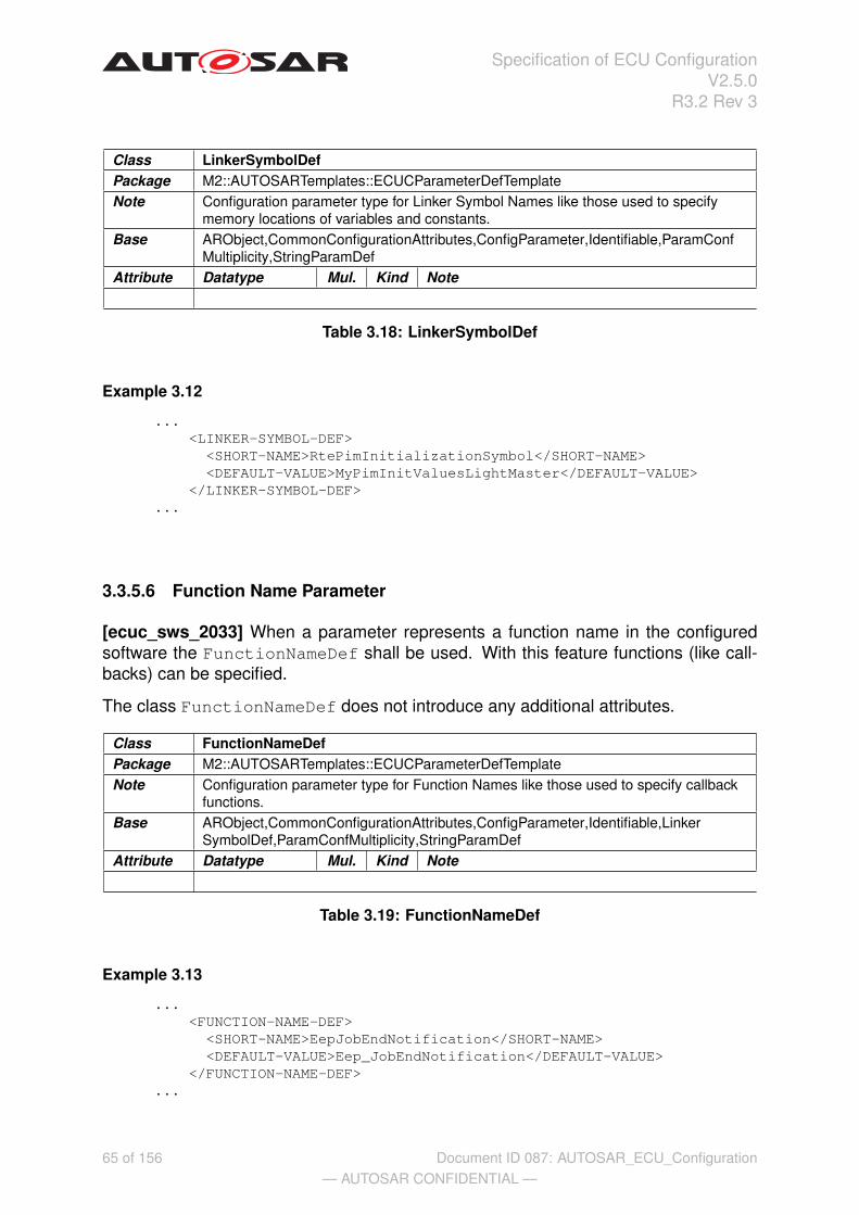
Specification of ECU ConfigurationV2.5.0
R3.2 Rev 3
Class LinkerSymbolDefPackage M2::AUTOSARTemplates::ECUCParameterDefTemplateNote Configuration parameter type for Linker Symbol Names like those used to specify
memory locations of variables and constants.Base ARObject,CommonConfigurationAttributes,ConfigParameter,Identifiable,ParamConf
Multiplicity,StringParamDefAttribute Datatype Mul. Kind Note
Table 3.18: LinkerSymbolDef
Example 3.12
...<LINKER-SYMBOL-DEF>
<SHORT-NAME>RtePimInitializationSymbol</SHORT-NAME><DEFAULT-VALUE>MyPimInitValuesLightMaster</DEFAULT-VALUE>
</LINKER-SYMBOL-DEF>...
3.3.5.6 Function Name Parameter
[ecuc_sws_2033] When a parameter represents a function name in the configuredsoftware the FunctionNameDef shall be used. With this feature functions (like call-backs) can be specified.
The class FunctionNameDef does not introduce any additional attributes.
Class FunctionNameDefPackage M2::AUTOSARTemplates::ECUCParameterDefTemplateNote Configuration parameter type for Function Names like those used to specify callback
functions.Base ARObject,CommonConfigurationAttributes,ConfigParameter,Identifiable,Linker
SymbolDef,ParamConfMultiplicity,StringParamDefAttribute Datatype Mul. Kind Note
Table 3.19: FunctionNameDef
Example 3.13
...<FUNCTION-NAME-DEF>
<SHORT-NAME>EepJobEndNotification</SHORT-NAME><DEFAULT-VALUE>Eep_JobEndNotification</DEFAULT-VALUE>
</FUNCTION-NAME-DEF>...
65 of 156— AUTOSAR CONFIDENTIAL —
Document ID 087: AUTOSAR_ECU_Configuration
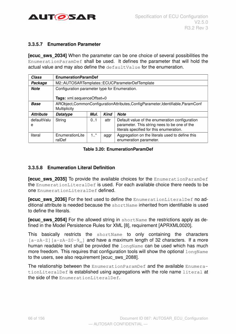
Specification of ECU ConfigurationV2.5.0
R3.2 Rev 3
3.3.5.7 Enumeration Parameter
[ecuc_sws_2034] When the parameter can be one choice of several possibilities theEnumerationParamDef shall be used. It defines the parameter that will hold theactual value and may also define the defaultValue for the enumeration.
Class EnumerationParamDefPackage M2::AUTOSARTemplates::ECUCParameterDefTemplateNote Configuration parameter type for Enumeration.
Tags: xml.sequenceOffset=0Base ARObject,CommonConfigurationAttributes,ConfigParameter,Identifiable,ParamConf
MultiplicityAttribute Datatype Mul. Kind NotedefaultValue
String 0..1 attr Default value of the enumeration configurationparameter. This string nees to be one of theliterals specified for this enumeration.
literal EnumerationLiteralDef
1..* aggr Aggregation on the literals used to define thisenumeration parameter.
Table 3.20: EnumerationParamDef
3.3.5.8 Enumeration Literal Definition
[ecuc_sws_2035] To provide the available choices for the EnumerationParamDefthe EnumerationLiteralDef is used. For each available choice there needs to beone EnumerationLiteralDef defined.
[ecuc_sws_2036] For the text used to define the EnumerationLiteralDef no ad-ditional attribute is needed because the shortName inherited from identifiable is usedto define the literals.
[ecuc_sws_2054] For the allowed string in shortName the restrictions apply as de-fined in the Model Persistence Rules for XML [8], requirement [APRXML0020].
This basically restricts the shortName to only containing the characters[a-zA-Z][a-zA-Z0-9_] and have a maximum length of 32 characters. If a morehuman readable text shall be provided the longName can be used which has muchmore freedom. This requires that configuration tools will show the optional longNameto the users, see also requirement [ecuc_sws_2088].
The relationship between the EnumerationParamDef and the available Enumera-tionLiteralDef is established using aggregations with the role name literal atthe side of the EnumerationLiteralDef.
66 of 156— AUTOSAR CONFIDENTIAL —
Document ID 087: AUTOSAR_ECU_Configuration

Specification of ECU ConfigurationV2.5.0
R3.2 Rev 3
Class EnumerationLiteralDefPackage M2::AUTOSARTemplates::ECUCParameterDefTemplateNote Configuration parameter type for enumeration literals definition.Base ARObject,IdentifiableAttribute Datatype Mul. Kind Note
Table 3.21: EnumerationLiteralDef
Example 3.14
...<ENUMERATION-PARAM-DEF>
<SHORT-NAME>RteGenerationMode</SHORT-NAME><DEFAULT-VALUE>CompatibilityMode</DEFAULT-VALUE><LITERALS>
<ENUMERATION-LITERAL-DEF><SHORT-NAME>CompatibilityMode</SHORT-NAME>
<LONG-NAME><L-4>Generate in Compatibility Mode</L-4></LONG-NAME></ENUMERATION-LITERAL-DEF><ENUMERATION-LITERAL-DEF>
<SHORT-NAME>VendorMode</SHORT-NAME><LONG-NAME><L-4>Generate in Vendor Mode</L-4></LONG-NAME>
</ENUMERATION-LITERAL-DEF></LITERALS>
</ENUMERATION-PARAM-DEF>...
3.3.6 References in Parameter Definition
There are five kinds of references available for the definition of configuration parame-ters referring to other entities.
• Reference to other configuration containers within the ECU Configuration De-scription (see section 3.3.6.1).
• A choice in the referenced configuration container can be specified and the ECUConfiguration Description has the freedom (with restrictions) to choose to whichtarget type the reference is pointing to (see section 3.3.6.2).
• Entities outside the ECU Configuration Description can be referenced when theyhave been specified in a different AUTOSAR Template (see section 3.3.6.3).
• Entities outside the ECU Configuration Description can be referenced using theinstanceRef semantics defined in the Template UML Profile and ModelingGuide [12] (see section 3.3.6.4).
• A container can be referenced to achieve a symbolic name semantics (see sec-tion 3.3.6.5).
67 of 156— AUTOSAR CONFIDENTIAL —
Document ID 087: AUTOSAR_ECU_Configuration

Specification of ECU ConfigurationV2.5.0
R3.2 Rev 3
The metamodel of those references is shown in figure 3.12.
ReferenceParamDef InstanceReferenceParamDef
+ destinationContext :String+ destinationType :String
ChoiceReferenceParamDef
CommonConfigurationAttributes
ConfigReference
ContainerDef
ParamConfContainerDef
+ multipleConfigurationContainer :Boolean
ForeignReferenceParamDef
+ destinationType :String
SymbolicNameReferenceParamDef
+destination 1
+reference *
+destination *
Figure 3.12: Class diagram for parameter references
[ecuc_sws_2037] The abstract class ConfigReference is used to specify the com-mon parts of all reference definitions. ConfigReference is an Identifiable soit is mandatory to give each reference a name. Also ConfigReference is inheritingfrom ParamConfMultiplicity so for each reference definition it can be specifiedhow many such references might be present in the same configuration container laterin the ECU Configuration Description.
Class ConfigReference (abstract)Package M2::AUTOSARTemplates::ECUCParameterDefTemplateNote Common class to gather the attributes for the definition of references.Base ARObject,CommonConfigurationAttributes,Identifiable,ParamConfMultiplicityAttribute Datatype Mul. Kind Note
Table 3.22: ConfigReference
3.3.6.1 Reference
[ecuc_sws_2039] The ReferenceParamDef is used to establish references fromone ParamConfContainerDef to one other specific ParamConfContainerDefwithin the same ECU Configuration Description. For this purpose an object repre-senting the reference has to be used.
[ecuc_sws_2038] The destination for the ReferenceParamDef and theChoiceReferenceParamDef is both the ParamConfContainerDef. So it isnot possible to reference to a specific ParameterDef directly but only to its container.
The reason is that there is no use-case where a direct reference to a parameter wouldbe needed.
68 of 156— AUTOSAR CONFIDENTIAL —
Document ID 087: AUTOSAR_ECU_Configuration

Specification of ECU ConfigurationV2.5.0
R3.2 Rev 3
Class ReferenceParamDefPackage M2::AUTOSARTemplates::ECUCParameterDefTemplateNote Specify references within the ECU Configuration Description between parameter
containers.Base ARObject,CommonConfigurationAttributes,ConfigReference,Identifiable,ParamConf
MultiplicityAttribute Datatype Mul. Kind Notedestination ParamConfCont
ainerDef1 ref Exactly one reference to an parameter container is
allowed as destination.
Table 3.23: ReferenceParamDef
The role name at the ReferenceParamDef has to be reference and the role nameat the referenced container has to be destination (see figure 3.13 for an example).
OsApplication :ParamConfContainerDef
upperMultiplicity = *lowerMultiplicity = 0
OsScheduleTable :ParamConfContainerDef
upperMultiplicity = *lowerMultipl icity = 0
OsAppScheduleTableRef :ReferenceParamDef
upperMultiplicity = *lowerMultiplicity = 0
+reference +destination
Figure 3.13: Example of an object diagram for a reference
In the example in figure 3.13 the ’OsApplication’ is defined to contain references tothe ’OsScheduleTable’. The references are called ’OsAppScheduleTableRef’ and therecan be several such references in the actual ECU Configuration Description document.For the multiplicity of references the multiplicity definition on the ReferenceParamDefare relevant (in the example the lowerMultiplicity is ’0’ and the upperMulti-plicity is ’*’). The multiplicity of the referenced container is not considered for refer-ences.
In the ECU Configuration Parameter Definition XML file the destination has to beidentified unambiguously because the names of configuration parameters are not re-quired to be unique throughout the whole ECU Configuration Parameter Definition. Sothere might be a parameter defined in the CAN-Driver with the same name as oneparameter defined in the ADC-Driver. For this reason the containment hierarchy ofthe referenced configuration parameter has to be denoted in the definition XML file, asshown in example 3.15. In this example the referenced parameter will be found in thedefinition of the Os module directly in the AUTOSARParameterDefinition.
69 of 156— AUTOSAR CONFIDENTIAL —
Document ID 087: AUTOSAR_ECU_Configuration

Specification of ECU ConfigurationV2.5.0
R3.2 Rev 3
Example 3.15
...<PARAM-CONF-CONTAINER-DEF>
<SHORT-NAME>OsApplication</SHORT-NAME><REFERENCES>
<REFERENCE-PARAM-DEF><SHORT-NAME>OsAppScheduleTableRef</SHORT-NAME><DESTINATION-REF DEST="PARAM-CONF-CONTAINER-DEF">
/AUTOSAR/Os/OsScheduleTable</DESTINATION-REF></REFERENCE-PARAM-DEF>
</REFERENCES></PARAM-CONF-CONTAINER-DEF>
...
70 of 156— AUTOSAR CONFIDENTIAL —
Document ID 087: AUTOSAR_ECU_Configuration

Specification of ECU ConfigurationV2.5.0
R3.2 Rev 3
3.3.6.2 Choice Reference
[ecuc_sws_2040] With the ChoiceReferenceParamDef it is possible to define onereference where the destination is specified to be one of several possible kinds. To beable to define such a choice an object of the class ChoiceReferenceParamDef hasto be aggregated in a container with the role name reference at the ChoiceRefer-enceParamDef object.
Class ChoiceReferenceParamDefPackage M2::AUTOSARTemplates::ECUCParameterDefTemplateNote Specify alternative references where in the ECU Configuration description only one of
the specified references will actually be used.Base ARObject,CommonConfigurationAttributes,ConfigReference,Identifiable,ParamConf
MultiplicityAttribute Datatype Mul. Kind Notedestination ParamConfCont
ainerDef* ref All the possible parameter containers for the
reference are specified.
Table 3.24: ChoiceReferenceParamDef
All the available choices are connected via associations with the role name destina-tion at the referenced object (see example in figure 3.14.
PortPin :ParamConfContainerDef
upperMultipl icity = *lowerMultipl icity = 0
PortPinMode :ChoiceReferenceParamDef
upperMultiplicity = *lowerMultiplicity = 1
CanDrvCanControl ler :ParamConfContainerDef
upperMultiplicity = *lowerMultiplicity = 1
AdcChannel :ParamConfContainerDef
upperMultipl icity = *lowerMultipl icity = 1
SpiCsDirect :ParamConfContainerDef
+reference
+destination+destination +destination
Figure 3.14: Example of an object diagram for a choice reference
In this example an actual instance of the ’PortPinMode’ container can reference one ofthe three defined containers. Once again the multiplicity is defined by the ChoiceRef-erenceParamDef (here the default ’1’ for lower and upper) and the multiplicities of thereferenced containers are not relevant for choice references.
Also the destination needs to be defined unambiguously in the ECU ConfigurationParameter Definition XML file like shown in example 3.16.
71 of 156— AUTOSAR CONFIDENTIAL —
Document ID 087: AUTOSAR_ECU_Configuration

Specification of ECU ConfigurationV2.5.0
R3.2 Rev 3
Example 3.16
...<PARAM-CONF-CONTAINER-DEF>
<SHORT-NAME>PortPin</SHORT-NAME><REFERENCES>
<CHOICE-REFERENCE-PARAM-DEF><SHORT-NAME>PortPinMode</SHORT-NAME><DESTINATION-REFS>
<DESTINATION-REF DEST="PARAM-CONF-CONTAINER-DEF">/AUTOSAR/Can/CanDrvCanController</DESTINATION-REF>
<DESTINATION-REF DEST="PARAM-CONF-CONTAINER-DEF">/AUTOSAR/Adc/AdcChannel</DESTINATION-REF>
<DESTINATION-REF DEST="PARAM-CONF-CONTAINER-DEF">/AUTOSAR/Spi/SpiCsDirect</DESTINATION-REF>
</DESTINATION-REFS></CHOICE-REFERENCE-PARAM-DEF>
</REFERENCES></PARAM-CONF-CONTAINER-DEF>
...
In the ECU Configuration Description the actual choice will be taken and there will beonly one reference destination left14.
14The ParamConfMultiplicity is used to specify the possible occurrences of each reference laterin the ECU Configuration Description. The ChoiceReference specifies multiple possible destinationsfor one reference but later in the ECU Configuration Description there can only be exactly one destinationdescribed. So the freedom of multiple destinations is only available on the definition of references, ifseveral containers need to be referenced the ParamConfMultiplicity has to be set to more than 1,even for the ChoiceReference.
72 of 156— AUTOSAR CONFIDENTIAL —
Document ID 087: AUTOSAR_ECU_Configuration
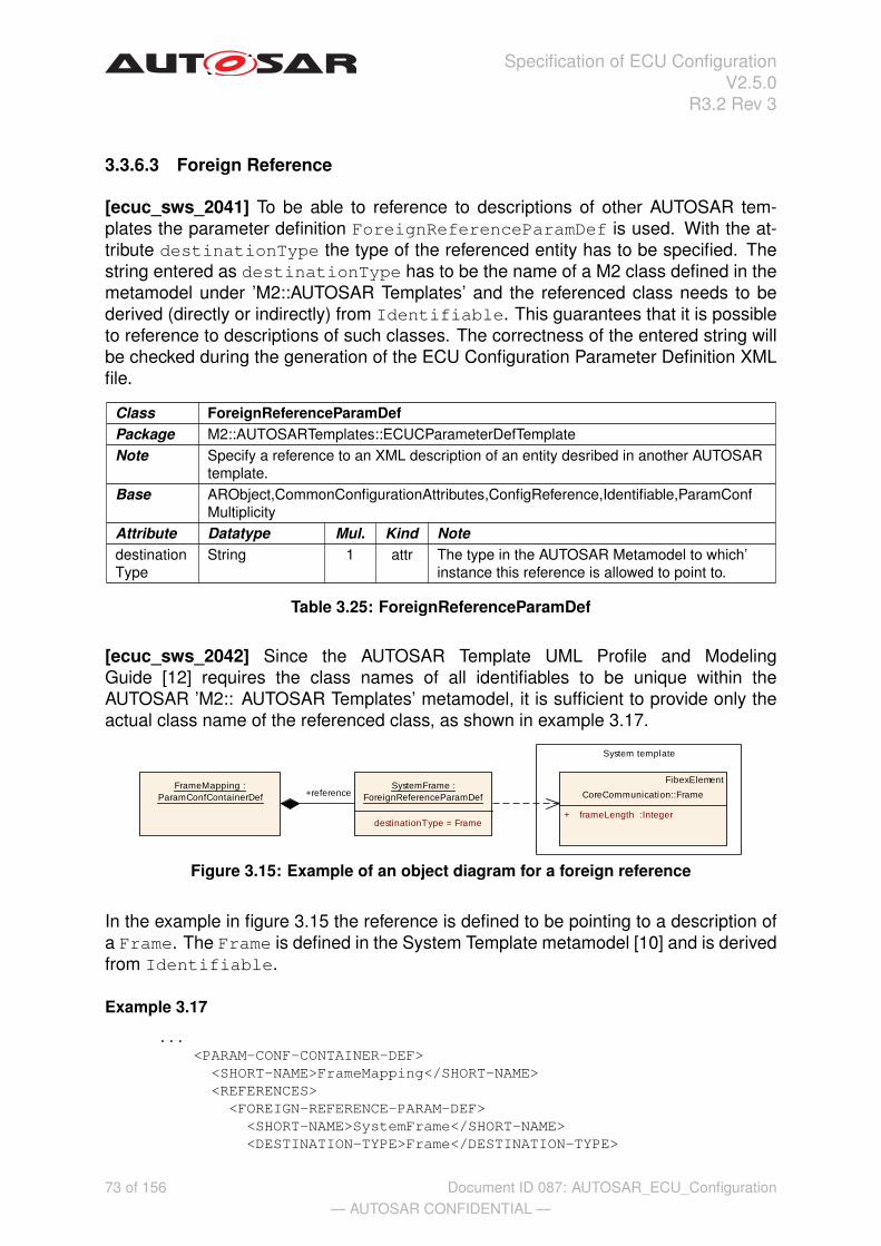
Specification of ECU ConfigurationV2.5.0
R3.2 Rev 3
3.3.6.3 Foreign Reference
[ecuc_sws_2041] To be able to reference to descriptions of other AUTOSAR tem-plates the parameter definition ForeignReferenceParamDef is used. With the at-tribute destinationType the type of the referenced entity has to be specified. Thestring entered as destinationType has to be the name of a M2 class defined in themetamodel under ’M2::AUTOSAR Templates’ and the referenced class needs to bederived (directly or indirectly) from Identifiable. This guarantees that it is possibleto reference to descriptions of such classes. The correctness of the entered string willbe checked during the generation of the ECU Configuration Parameter Definition XMLfile.
Class ForeignReferenceParamDefPackage M2::AUTOSARTemplates::ECUCParameterDefTemplateNote Specify a reference to an XML description of an entity desribed in another AUTOSAR
template.Base ARObject,CommonConfigurationAttributes,ConfigReference,Identifiable,ParamConf
MultiplicityAttribute Datatype Mul. Kind NotedestinationType
String 1 attr The type in the AUTOSAR Metamodel to which’instance this reference is allowed to point to.
Table 3.25: ForeignReferenceParamDef
[ecuc_sws_2042] Since the AUTOSAR Template UML Profile and ModelingGuide [12] requires the class names of all identifiables to be unique within theAUTOSAR ’M2:: AUTOSAR Templates’ metamodel, it is sufficient to provide only theactual class name of the referenced class, as shown in example 3.17.
SystemFrame :ForeignReferenceParamDef
destinationType = Frame
FrameMapping :ParamConfContainerDef
System template
FibexElement
CoreCommunication::Frame
+ frameLength :Integer
+reference
Figure 3.15: Example of an object diagram for a foreign reference
In the example in figure 3.15 the reference is defined to be pointing to a description ofa Frame. The Frame is defined in the System Template metamodel [10] and is derivedfrom Identifiable.
Example 3.17
...<PARAM-CONF-CONTAINER-DEF>
<SHORT-NAME>FrameMapping</SHORT-NAME><REFERENCES>
<FOREIGN-REFERENCE-PARAM-DEF><SHORT-NAME>SystemFrame</SHORT-NAME><DESTINATION-TYPE>Frame</DESTINATION-TYPE>
73 of 156— AUTOSAR CONFIDENTIAL —
Document ID 087: AUTOSAR_ECU_Configuration
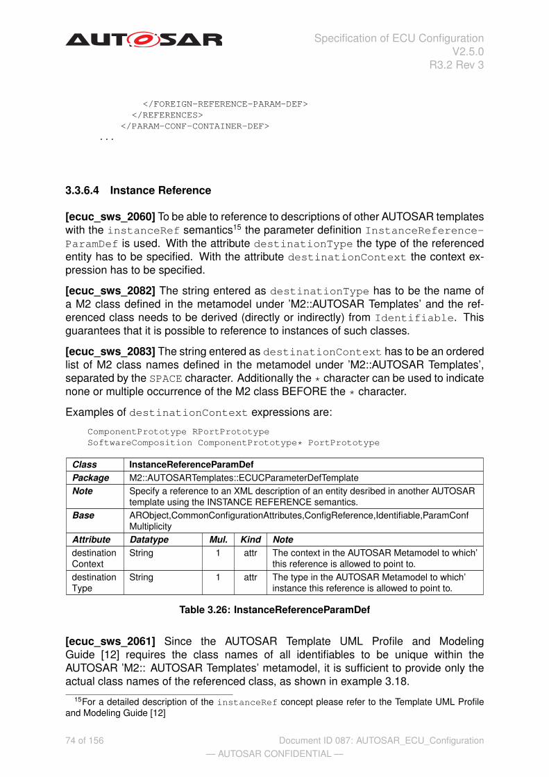
Specification of ECU ConfigurationV2.5.0
R3.2 Rev 3
</FOREIGN-REFERENCE-PARAM-DEF></REFERENCES>
</PARAM-CONF-CONTAINER-DEF>...
3.3.6.4 Instance Reference
[ecuc_sws_2060] To be able to reference to descriptions of other AUTOSAR templateswith the instanceRef semantics15 the parameter definition InstanceReference-ParamDef is used. With the attribute destinationType the type of the referencedentity has to be specified. With the attribute destinationContext the context ex-pression has to be specified.
[ecuc_sws_2082] The string entered as destinationType has to be the name ofa M2 class defined in the metamodel under ’M2::AUTOSAR Templates’ and the ref-erenced class needs to be derived (directly or indirectly) from Identifiable. Thisguarantees that it is possible to reference to instances of such classes.
[ecuc_sws_2083] The string entered as destinationContext has to be an orderedlist of M2 class names defined in the metamodel under ’M2::AUTOSAR Templates’,separated by the SPACE character. Additionally the * character can be used to indicatenone or multiple occurrence of the M2 class BEFORE the * character.
Examples of destinationContext expressions are:
ComponentPrototype RPortPrototypeSoftwareComposition ComponentPrototype* PortPrototype
Class InstanceReferenceParamDefPackage M2::AUTOSARTemplates::ECUCParameterDefTemplateNote Specify a reference to an XML description of an entity desribed in another AUTOSAR
template using the INSTANCE REFERENCE semantics.Base ARObject,CommonConfigurationAttributes,ConfigReference,Identifiable,ParamConf
MultiplicityAttribute Datatype Mul. Kind NotedestinationContext
String 1 attr The context in the AUTOSAR Metamodel to which’this reference is allowed to point to.
destinationType
String 1 attr The type in the AUTOSAR Metamodel to which’instance this reference is allowed to point to.
Table 3.26: InstanceReferenceParamDef
[ecuc_sws_2061] Since the AUTOSAR Template UML Profile and ModelingGuide [12] requires the class names of all identifiables to be unique within theAUTOSAR ’M2:: AUTOSAR Templates’ metamodel, it is sufficient to provide only theactual class names of the referenced class, as shown in example 3.18.
15For a detailed description of the instanceRef concept please refer to the Template UML Profileand Modeling Guide [12]
74 of 156— AUTOSAR CONFIDENTIAL —
Document ID 087: AUTOSAR_ECU_Configuration
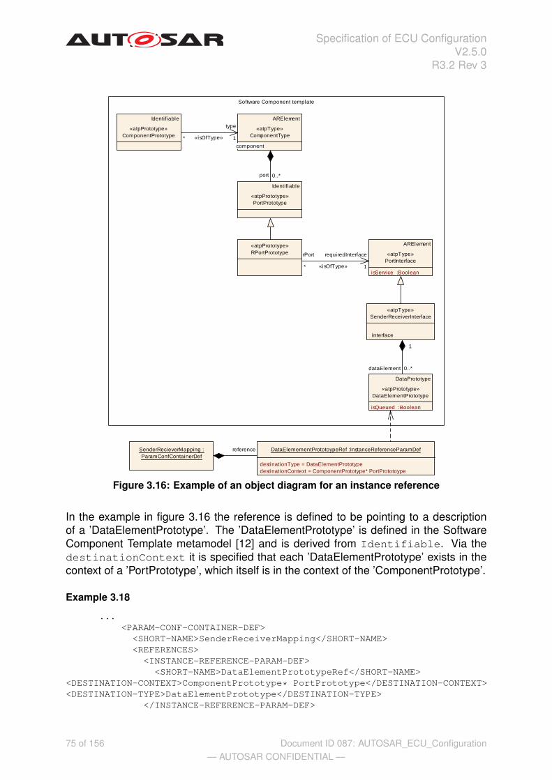
Specification of ECU ConfigurationV2.5.0
R3.2 Rev 3
Software Component template
DataPrototype
«atpPrototype»DataElementPrototype
isQueued :Boolean
Identifiable
«atpPrototype»ComponentPrototype
«atpType»SenderReceiverInterface
ARElement
«atpType»PortInterface
isService :Boolean
«atpPrototype»RPortPrototype
Identifiable
«atpPrototype»PortPrototype
ARElement
«atpType»ComponentType
DataElemementPrototoypeRef :InstanceReferenceParamDef
destinationType = DataElementPrototypedestinationContext = ComponentPrototype* PortPrototoype
SenderRecieverMapping :ParamConfContainerDef
dataElement 0..*
interface
1
port 0..*
component
* «isOfType»
type
1
rPort
* «isOfType»
requiredInterface
1
reference
Figure 3.16: Example of an object diagram for an instance reference
In the example in figure 3.16 the reference is defined to be pointing to a descriptionof a ’DataElementPrototype’. The ’DataElementPrototype’ is defined in the SoftwareComponent Template metamodel [12] and is derived from Identifiable. Via thedestinationContext it is specified that each ’DataElementPrototype’ exists in thecontext of a ’PortPrototype’, which itself is in the context of the ’ComponentPrototype’.
Example 3.18
...<PARAM-CONF-CONTAINER-DEF>
<SHORT-NAME>SenderReceiverMapping</SHORT-NAME><REFERENCES>
<INSTANCE-REFERENCE-PARAM-DEF><SHORT-NAME>DataElementPrototypeRef</SHORT-NAME>
<DESTINATION-CONTEXT>ComponentPrototype* PortPrototype</DESTINATION-CONTEXT><DESTINATION-TYPE>DataElementPrototype</DESTINATION-TYPE>
</INSTANCE-REFERENCE-PARAM-DEF>
75 of 156— AUTOSAR CONFIDENTIAL —
Document ID 087: AUTOSAR_ECU_Configuration

Specification of ECU ConfigurationV2.5.0
R3.2 Rev 3
</REFERENCES></PARAM-CONF-CONTAINER-DEF>
...
Although the ECU Configuration Parameter Definition of the ForeignReferen-ceParamDef and InstanceReferenceParamDef are similar there is a differencehow those references are represented in the ECU Configuration Description (see sec-tion 3.4.5).
76 of 156— AUTOSAR CONFIDENTIAL —
Document ID 087: AUTOSAR_ECU_Configuration

Specification of ECU ConfigurationV2.5.0
R3.2 Rev 3
3.3.6.5 Symbolic Name Reference
[ecuc_sws_2032] The SymbolicNameReferenceParamDef is used to establish therelationship between the user of a symbolic name and the provider of a symbolicname. The object defining the SymbolicNameReferenceParamDef is the user andthe destination of the reference is the provider of the symbolic name.
The SymbolicNameReferenceParamDef inherits from ReferenceParamDef, so itcan be used to point to elements of the kind of ParamConfContainerDef within theECU Configuration Description only.
Class SymbolicNameReferenceParamDefPackage M2::AUTOSARTemplates::ECUCParameterDefTemplateNote This specialization of a ReferenceParamDef specifies that the implementation of the
reference is done using a symbolic name defined by the referenced Container’sshortName.
Base ARObject,CommonConfigurationAttributes,ConfigReference,Identifiable,ParamConfMultiplicity,ReferenceParamDef
Attribute Datatype Mul. Kind Note
Table 3.27: SymbolicNameReferenceParamDef
[ecuc_sws_2063] If the attribute symbolicNameValue of a configuration parameter(see section 3.3.5) is set to true this configuration parameter is used as the actualvalue for the symbolic name. Only one configuration parameter within a container mayhave this attribute set to true.
If the attribute is not present it shall be assumed to be set to false.
In the example definition shown in figure 3.17 the IoHwAb module can contain severalIoHwAbDemErrors. Those errors need to be defined in the Dem module. And onlythe Dem module is able to define actual numbers associated with these errors when allerrors have been specified and collected in the Dem module. Those associated valuescan be stored in the DemErrorId parameter which belongs to each DemError.
For an example how this is used in the ECU Configuration Description refer to sec-tion 3.4.5.2.
DemError :ParamConfContainerDef
upperMultipl icity = *lowerMultipl icity = 0
Dem :ModuleDef
IoHwAb :ModuleDef IoHwAbDemError :ParamConfContainerDef
upperMultipl icity = *lowerMultipl icity = 0
DemErrorRef :SymbolicNameReferenceParamDef
DemErrorId :IntegerParamDef
upperMultiplicity = 1lowerMultiplicity = 1symbolicNameValue = true
+reference+container
+container+parameter
+destination
Figure 3.17: Example of an object diagram for a Symbolic Name Reference
77 of 156— AUTOSAR CONFIDENTIAL —
Document ID 087: AUTOSAR_ECU_Configuration

Specification of ECU ConfigurationV2.5.0
R3.2 Rev 3
Example 3.19
...<MODULE-DEF>
<SHORT-NAME>IoHwAb</SHORT-NAME><CONTAINERS>
<PARAM-CONF-CONTAINER-DEF><SHORT-NAME>IoHwAbDemError</SHORT-NAME><LOWER-MULTIPLICITY>0</LOWER-MULTIPLICITY><UPPER-MULTIPLICITY>*</UPPER-MULTIPLICITY><REFERENCES>
<SYMBOLIC-NAME-REFERENCE-PARAM-DEF><SHORT-NAME>DemErrorRef</SHORT-NAME><DESTINATION-REF DEST="PARAM-CONF-CONTAINER-DEF">
/AUTOSAR/Dem/DemError</DESTINATION-REF></SYMBOLIC-NAME-REFERENCE-PARAM-DEF>
</REFERENCES></PARAM-CONF-CONTAINER-DEF>
</CONTAINERS></MODULE-DEF><MODULE-DEF>
<SHORT-NAME>Dem</SHORT-NAME><CONTAINERS>
<PARAM-CONF-CONTAINER-DEF><SHORT-NAME>DemError</SHORT-NAME><LOWER-MULTIPLICITY>0</LOWER-MULTIPLICITY><UPPER-MULTIPLICITY>*</UPPER-MULTIPLICITY><PARAMETERS>
<INTEGER-PARAM-DEF><SHORT-NAME>DemErrorId</SHORT-NAME><LOWER-MULTIPLICITY>1</LOWER-MULTIPLICITY><UPPER-MULTIPLICITY>1</UPPER-MULTIPLICITY><SYMBOLIC-NAME-VALUE>true</SYMBOLIC-NAME-VALUE>
</INTEGER-PARAM-DEF></PARAMETERS>
</PARAM-CONF-CONTAINER-DEF></CONTAINERS>
</MODULE-DEF>...
3.3.7 Derived Parameter Definition
The parameter definitions introduced in the previous sections are meant to define con-figuration parameter types regardless how the actual values will be captured. But sincethe ECU Configuration is dependent on lots of other input information many valuesfor the configuration of the BSW and the RTE can be taken over or calculated fromother values already available in another description (e.g. the System Extract or theSoftware-Component description). Such configuration parameters are called DerivedConfiguration Parameters.
78 of 156— AUTOSAR CONFIDENTIAL —
Document ID 087: AUTOSAR_ECU_Configuration

Specification of ECU ConfigurationV2.5.0
R3.2 Rev 3
[ecuc_sws_2046] For the major configuration parameter types defined in section 3.3.5there is a specialization specified which does represent a Derived Configuration Pa-rameter.
The available Derived Configuration Parameters are illustrated in figure 3.18. The ab-stract class DerivedValueType does provide the common attributes for all inheritingparameter definitions.
ContainerDef
ECUCParameterDefTemplate::ParamConfContainerDef
+ multipleConfigurationContainer :Boolean
ECUCParameterDefTemplate::DerivedParamType
+ calculationFormula :String+ calculationLanguage :CalculationLanguage
ECUCParameterDefTemplate::DerivedIntegerParamDef
ECUCParameterDefTemplate::DerivedBooleanParamDef
ECUCParameterDefTemplate::DerivedFloatParamDef
ECUCParameterDefTemplate::DerivedStringParamDef
ECUCParameterDefTemplate::DerivedEnumerationParamDef
Identifiable
ECUCParameterDefTemplate::EnumerationLiteralDef
CommonConfigurationAttributes
ECUCParameterDefTemplate::ConfigParameter
+ symbolicNameValue :Boolean
ECUCParameterDefTemplate::BooleanParamDef
+ defaultValue :Boolean [0..1]
ECUCParameterDefTemplate::IntegerParamDef
+ defaultValue :UnlimitedInteger [0..1]+ max :UnlimitedInteger [0..1]+ min :UnlimitedInteger [0..1]
ECUCParameterDefTemplate::FloatParamDef
+ defaultValue :Float [0..1]+ max :Float [0..1]+ min :Float [0..1]
ECUCParameterDefTemplate::StringParamDef
+ defaultValue :String [0..1]
ECUCParameterDefTemplate::EnumerationParamDef
+ defaultValue :String [0..1]
«enumeration»ECUCParameterDefTemplate::
CalculationLanguage
informal ARformal
+literal 1..*
+parameter
*
Figure 3.18: Definition of Derived Parameters
Class DerivedParamType (abstract)Package M2::AUTOSARTemplates::ECUCParameterDefTemplateNote Allows to define configuration items that are calculated based on the value of
• other parameters values
• elements (attributes /classes) defined in other AUTOSAR templates such asSystem template and SW component template.
A calculation definition is given which defines how Configuration Editors andGenerators can calculate the value from other values when needed to display/use theconfiguration item. The actual value is stored in the "value" attribute of the derivedparameter.
Tags: xml.sequenceOffset=40Base ARObjectAttribute Datatype Mul. Kind NotecalculationFormula
String 1 attr Definition of the formula used to calculate thevalue of the configuration element.
79 of 156— AUTOSAR CONFIDENTIAL —
Document ID 087: AUTOSAR_ECU_Configuration
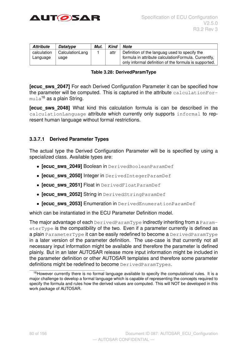
Specification of ECU ConfigurationV2.5.0
R3.2 Rev 3
Attribute Datatype Mul. Kind NotecalculationLanguage
CalculationLanguage
1 attr Definition of the languag used to specify theformula in attribute calculationFormula. Currentlfy,only informal definition of the formula is supported.
Table 3.28: DerivedParamType
[ecuc_sws_2047] For each Derived Configuration Parameter it can be specified howthe parameter will be computed. This is captured in the attribute calculationFor-mula16 as a plain String.
[ecuc_sws_2048] What kind this calculation formula is can be described in thecalculationLanguage attribute which currently only supports informal to rep-resent human language without formal restrictions.
3.3.7.1 Derived Parameter Types
The actual type the Derived Configuration Parameter will be is specified by using aspecialized class. Available types are:
• [ecuc_sws_2049] Boolean in DerivedBooleanParamDef
• [ecuc_sws_2050] Integer in DerivedIntegerParamDef
• [ecuc_sws_2051] Float in DerivedFloatParamDef
• [ecuc_sws_2052] String in DerivedStringParamDef
• [ecuc_sws_2053] Enumeration in DerivedEnumerationParamDef
which can be instantiated in the ECU Parameter Definition model.
The major advantage of each DerivedParamType indirectly inheriting from a Param-eterType is the compatibility of the two. Even if a parameter currently is defined asa plain ParameterType it can be easily redefined to become a DerivedParamTypein a later version of the parameter definition. The use-case is that currently not allnecessary input information might be available and therefore the parameter is definedplainly. But in an later AUTOSAR release more input information might be included inthe parameter definition or other AUTOSAR templates and therefore some parameterdefinitions might be redefined to become DerivedParamTypes.
16However currently there is no formal language available to specify the computational rules. It is amajor challenge to develop a formal language which is capable of representing the concepts required tospecify the formula and rules how the derived values are computed. This will NOT be developed in thiswork package of AUTOSAR.
80 of 156— AUTOSAR CONFIDENTIAL —
Document ID 087: AUTOSAR_ECU_Configuration

Specification of ECU ConfigurationV2.5.0
R3.2 Rev 3
3.3.7.2 Derived Parameter Calculation Formula
For the content of the calculationFormula of Derived Configuration Parametersthe references do provide essential information. Since the calculationFormulaprovides information how the values can be computed it utilizes the references to ad-dress foreign elements to gather the needed information.
The DerivedParamType and the ConfigReference are both defined within thecontext of a ParamConfContainerDef and therefore belong to the same name-space. In the calculationFormula this is used to address the different parts thevalue needs to be derived from. This is shown in the example 3.20 which representsthe XML for figure 3.19.
System Description Template
SignalDefinitionSystemDesc :ForeignReferenceParamDef
destinationType = ISignalToIPduMapping
SystemSignal
+ length :Integer
ComSigBitPosition :DerivedIntegerParamDef
calculationLanguage = informal
ComSigSizeInBits :DerivedIntegerParamDef
calculationLanguage = informal
ComSigEndianess :DerivedEnumerationParamDef
calculationLanguage = informal
LittleEndian :EnumerationLiteralDef
BigEndian :EnumerationLiteralDef
Identifiable
ISignalToIPduMapping
+ packingByteOrder :ByteOrderEnum+ startPosition :Integer [0..1]+ transferProperty :TransferPropertyEnum [0..1]+ updateIndicationBitPosition :Integer [0..1]
ARElement
AbstractSignal
FibexElement
ISignal
ComSignal :ParamConfContainerDef
+parameter +parameter
+parameter
+reference
1..*+signal 1
1..*+systemSignal 1
+literal+l iteral
Figure 3.19: Example of derived parameters
In this example the container is called ComSignal and it has a foreign reference calledSignalDefinitionSystemDescription to an instance of type ISignalToIP-duMapping from the System Description Template. The ISignalToIPduMappinghas attributes itself and also references to the ISignal which itself references to theSystemSignal, all in the System Description Template.
The three defined Derived Configuration Parameters have an informal calcula-tionFormula which is not shown in the figure but is shown in the XML example.
81 of 156— AUTOSAR CONFIDENTIAL —
Document ID 087: AUTOSAR_ECU_Configuration

Specification of ECU ConfigurationV2.5.0
R3.2 Rev 3
Example 3.20
...<PARAM-CONF-CONTAINER-DEF>
<SHORT-NAME>ComSignal</SHORT-NAME><PARAMETERS>
<DERIVED-INTEGER-PARAM-DEF><SHORT-NAME>ComSigBitPosition</SHORT-NAME><CALCULATION-FORMULA>
value = SignalDefinitionSystemDesc.startPosition</CALCULATION-FORMULA><CALCULATION-LANGUAGE>INFORMAL</CALCULATION-LANGUAGE>
</DERIVED-INTEGER-PARAM-DEF><DERIVED-INTEGER-PARAM-DEF>
<SHORT-NAME>ComSigSizeInBits</SHORT-NAME><CALCULATION-FORMULA>
value = SignalDefinitionSystemDesc.signal.systemSignal.length</CALCULATION-FORMULA><CALCULATION-LANGUAGE>INFORMAL</CALCULATION-LANGUAGE>
</DERIVED-INTEGER-PARAM-DEF><DERIVED-ENUMERATION-PARAM-DEF>
<SHORT-NAME>ComSigEndianess</SHORT-NAME><LITERALS>
<ENUMERATION-LITERAL-DEF><SHORT-NAME>LittleEndian</SHORT-NAME>
</ENUMERATION-LITERAL-DEF><ENUMERATION-LITERAL-DEF>
<SHORT-NAME>BigEndian</SHORT-NAME></ENUMERATION-LITERAL-DEF>
</LITERALS><CALCULATION-FORMULA>
if(SignalDefinitionSystemDesc.packingByteOrder==LittleEndian){value = LittleEndian }
if(SignalDefinitionSystemDesc.packingByteOrder==BigEndian){value = BigEndian }
</CALCULATION-FORMULA><CALCULATION-LANGUAGE>INFORMAL</CALCULATION-LANGUAGE>
</DERIVED-ENUMERATION-PARAM-DEF></PARAMETERS><REFERENCES>
<FOREIGN-REFERENCE-PARAM-DEF><SHORT-NAME>SignalDefinitionSystemDesc</SHORT-NAME><DESTINATION-TYPE>ISignalToIPduMapping</DESTINATION-TYPE>
</FOREIGN-REFERENCE-PARAM-DEF></REFERENCES>
</PARAM-CONF-CONTAINER-DEF>...
Although the calculationFormula is set to INFORMAL there can be some program-ming language syntax and semantics interpreted.
Since the foreign reference SignalDefinitionSystemDesc is present in the samecontainer as the derived parameter definitions it is possible to address the reference
82 of 156— AUTOSAR CONFIDENTIAL —
Document ID 087: AUTOSAR_ECU_Configuration

Specification of ECU ConfigurationV2.5.0
R3.2 Rev 3
directly using its name. In the formula of ComSigBitPosition the attributes of thereferenced element can be queried and assigned to the value of this derived parameter.
In the ComSigSizeInBits also the reference is used but then another referencewithin the System Description is followed with the . operator. Then again the attributevalue is assigned to the value of the derived parameter.
In the last example section on ComSigEndianess there is actual some logic describedusing if clauses to define a mapping from the System Description naming to the ECUConfiguration naming.
Those have been just three short examples how a calculationFormula might becomposed. Since currently only informal description are supported also a combinationof natural language with such references is possible to express more complex relation-ships.
3.3.7.3 Restrictions on Configuration Class of Derived Parameters
Derived Parameters have to be defined similar to plain configuration parameters whichmeans that also the configuration class has to be specified in the actual implementationof the configuration. But since derived parameters do depend on other informationthere are certain restrictions applicable which reduce the degree of freedom what kindof configuration class a derived parameter might be.
[ecuc_sws_2055] If the derived parameter is only derived from information comingfrom other AUTOSAR templates using the ForeignReferenceParamDef or In-stanceReferenceParamDef relationship it is assumed that those documents do notchange during the configuration process and therefore there are no restrictions on theconfiguration class of derived parameters.
If the derived parameter is derived from other Configuration Parameters in the ECUConfiguration Description then certain rules have to be applied:
• [ecuc_sws_2058] If the derived parameter uses information from parametersdefined as PreCompile then the derived parameter can be any configurationclass.
• [ecuc_sws_2056] If the derived parameter uses information from parametersdefined as Link then the derived parameter needs to be Link or PostBuildconfigurable.
• [ecuc_sws_2057] If the derived parameter uses information from parameters de-fined as PostBuild then the derived parameter needs to be PostBuild con-figurable as well.
83 of 156— AUTOSAR CONFIDENTIAL —
Document ID 087: AUTOSAR_ECU_Configuration

Specification of ECU ConfigurationV2.5.0
R3.2 Rev 3
3.4 ECU Configuration Description Metamodel
As mentioned in section 3.2 the ECU Configuration Definition metamodel provides themeans to declare the parameters and their permitted occurrences within a configura-tion file. This section will specify the complement to that ECU Configuration ParameterDefinition on the actual description side, namely the ECU Configuration Description.
In general, the structure of the ECU Configuration Description metamodel followsthe same approach the parameter definition is based upon. One important differ-ence is the fact that there are no special configuration descriptions for ChoiceRef-erenceParamDef, ForeignReferenceParamDef, DerivedParamDef and Sym-bolicNameReferenceParamDef. How the ECU Configuration Description handlesthese definition types is described in the appropriate sections below. Because of theseprerequisites the ECU Configuration Description metamodel is kept very simple.
The following sections will depict the ECU Configuration Description metamodel. Sec-tions 3.4.1 and 3.4.2 will introduce the top-level structure of a configuration descriptionand the module configurations, whereas the sections 3.4.3, 3.4.4 and 3.4.5 will de-scribe the means to file and structure the actual configuration values.
3.4.1 ECU Configuration Description Top-Level Structure
The top-level entry point to an AUTOSAR ECU Configuration Description is the Ecu-Configuration (see figure 3.20). Because of the inheritance from ARElement theEcuConfiguration can be part of an AUTOSAR description like its counterpart theEcuParameterDefinition does. A valid EcuConfiguration needs to referencethe System description (provided as an ecuExtract) [10] that specifies the environ-ment in which the configured ECU operates. Additionally it references all SoftwareModule configurations (see section 3.4.2) that are part of this ECU Configuration.
84 of 156— AUTOSAR CONFIDENTIAL —
Document ID 087: AUTOSAR_ECU_Configuration

Specification of ECU ConfigurationV2.5.0
R3.2 Rev 3
Identifiable
ECUCDescriptionTemplate::Container
ARElement
ECUCDescriptionTemplate::EcuConfiguration
ARElement
«atpStructureElement»SystemTemplate::System
+ ecuExtractVersion :String [0..1]+ pncVectorLength :Integer [0..1]+ pncVectorOffset :Integer [0..1]+ systemVersion :String
ARElement
ECUCParameterDefTemplate::EcuParameterDefinition
ARElement
ECUCDescriptionTemplate::ModuleConfiguration
+ implementationConfigVariant :ConfigurationVariant
ARElementParamConfMultiplicity
ECUCParameterDefTemplate::ModuleDef
+ apiServicePrefix :CIdentifier [0..1]+ supportedConfigVariant :ConfigurationVariant [1..*]
«enumeration»ECUCParameterDefTemplate::
ConfigurationVariant
VariantPreCompile VariantLinkTime VariantPostBuild VariantPostBuildLoadable VariantPostBuildSelectable
ARElementImplementation
BswImplementation::BswImplementation
+ arMajorVersion :Integer+ arMinorVersion :Integer+ arPatchVersion :Integer+ vendorApiInfix :String
IdentifiableParamConfMultipl icity
ECUCParameterDefTemplate::ContainerDef
+ postBuildChangeable :Boolean
+ecuExtract
1
+module 1..*
+container 1..*«spli table»
0..1
+module 1..*
+definition
1
+container 1..*
+subContainer *«splitable»
0..1
+moduleDescription
0..1
«splitable»
+definition
1
Figure 3.20: ECU Configuration Description Top-Level Structure
Class EcuConfigurationPackage M2::AUTOSARTemplates::ECUCDescriptionTemplateNote This represents the anchor point of the ECU configuration description.Base ARElement,ARObject,Identifiable,PackageableElementAttribute Datatype Mul. Kind NoteecuExtract System 1 ref Represents the extract of the System
Configuration that is relevant for the ECUconfigured with that ECU ConfigurationDescription.
ecuSwComposition
EcuSwComposition
1 ref Reference to the EcuSwComposition which holdsthe AUTOSAR Service Software Components.
module ModuleConfiguration
1..* ref References to the configuration of individualsoftware modules that are present on this ECU.
Table 3.29: EcuConfiguration
3.4.2 Module Configurations
[ecuc_sws_3016] The ModuleConfiguration subsumes all configuration objectsthat belong to one managed Software Module, namely Application Software Compo-nents, BSW modules, RTE and generic ECU Configuration artifacts (e.g. memorymaps).
[ecuc_sws_2089] The ModuleConfiguration aggregates the Container with therole container and the stereotype «splitable» which allows the content of a Mod-uleConfiguration to be split among several XML-Files (see also section 3.4.2.1).
[ecuc_sws_3017] If the ModuleConfiguration holds the configuration values of aBSW module, a reference to the according BswImplementation shall be provided.
The reference is established to the BswImplementation because this is the mostdetailed information available for the configuration.
85 of 156— AUTOSAR CONFIDENTIAL —
Document ID 087: AUTOSAR_ECU_Configuration

Specification of ECU ConfigurationV2.5.0
R3.2 Rev 3
[ecuc_sws_3035] The reference definition assigns the ModuleConfigurationto the according ModuleDef it is depending on.
[ecuc_sws_3031] The ModuleDef, to which the ModuleConfiguration is associ-ated to, is specified by the implementor of the according Software Module. Thereforethe ModuleDef includes standardized as well as vendor-specific parameter definitions.
Class ModuleConfigurationPackage M2::AUTOSARTemplates::ECUCDescriptionTemplateNote Head of the configuration of one Module. A Module can be a BSW module as well as
the RTE and ECU Infrastructure.
As part of tthe BSW module description, the ModuleConfiguration has two differentroles:
The recommendedConfiguration contains parameter values recommended by theBSW module vendor.
The preconfiguredConfiguration contains values for those parameters which are fixedby the implementation and cannot be changed.
These two ModuleConfigurations are used when the base ModuleConfiguration (aspart of the base ECU configuration) is created to fill parameters with initial values.
Base ARElement,ARObject,Identifiable,PackageableElementAttribute Datatype Mul. Kind Notecontainer Container 1..* aggr Aggregates all containers that belong to this
module configuration.
Stereotypes: atpSplitableTags: xml.sequenceOffset=10
definition ModuleDef 1 ref Reference to the definition of thisModuleConfiguration. Typically, this is a vendorspecific module configuration.
Tags: xml.sequenceOffset=-10implementationConfigVariant
ConfigurationVariant
1 attr Specifies the ConfigurationVariant used for thisModuleConfiguration.
moduleDescription
BswImplementation
0..1 ref Referencing the BSW module description, whichthis ModuleConfiguration is configuring. This isoptional because the ModuleConfiguration is alsoused to configure the ECU infrastructure (memorymap) or Application SW-Cs.
Table 3.30: ModuleConfiguration
86 of 156— AUTOSAR CONFIDENTIAL —
Document ID 087: AUTOSAR_ECU_Configuration

Specification of ECU ConfigurationV2.5.0
R3.2 Rev 3
Figure 3.21 depicts the different associations between the ModuleConfigura-tion and the Basic Software Module Description. The BswImplemen-tation may specify a vendor specific pre-configured configuration description(preconfiguredConfiguration) that includes the configuration values already as-signed by the implementor of the Software Module and a vendor specific recommendedconfiguration description (recommendedConfiguration) that can be used to initial-ize configuration editors.
ARElement
ECUCDescriptionTemplate::EcuConfiguration
ARElement
«atpStructureElement»SystemTemplate::System
+ ecuExtractVersion :String [0..1]+ pncVectorLength :Integer [0..1]+ pncVectorOffset :Integer [0..1]+ systemVersion :String
ARElement
ECUCParameterDefTemplate::EcuParameterDefinition
ARElement
ECUCDescriptionTemplate::ModuleConfiguration
+ implementationConfigVariant :ConfigurationVariant
ARElementParamConfMultiplicity
ECUCParameterDefTemplate::ModuleDef
+ apiServicePrefix :CIdentifier [0..1]+ supportedConfigVariant :ConfigurationVariant [1..*]
ARElementImplementation
BswImplementation::BswImplementation
+ arMajorVersion :Integer+ arMinorVersion :Integer+ arPatchVersion :Integer+ vendorApiInfix :String
ARElement
«atpStructureElement»Services::
EcuSwComposition
+ecuSwComposition 1
+moduleDescription 0..1
+module 1..*
+preconfiguredConfiguration 0..1+recommendedConfiguration 0..1
+definition
1
+module 1..*
+vendorSpecificModuleDef
1
+refinedModuleDef 0..1
+ecuExtract 1
+ecuExtract
1
Figure 3.21: Dependencies of ModuleConfigurations
[ecuc_sws_2103] The implementationConfigVariant specifies which configu-ration variant has been chosen for this ModuleConfiguration. The choice is takenfrom the supportedConfigVariant elements specified in the ModuleDef associ-ated to this ModuleConfiguration.
The element supportedConfigVariant is described in section 3.3.2 and sec-tion 3.3.4.2.2.
To illustrate the structure of an ECU Configuration Description example 3.21 depictsthe top-level structure of an ECU Configuration Description XML file that conforms tothe ECU Configuration Definition XML file that was presented in example 3.3.
The only supportedConfigVariant of example 3.3 is taken for the implementa-tionConfigVariant element.
87 of 156— AUTOSAR CONFIDENTIAL —
Document ID 087: AUTOSAR_ECU_Configuration
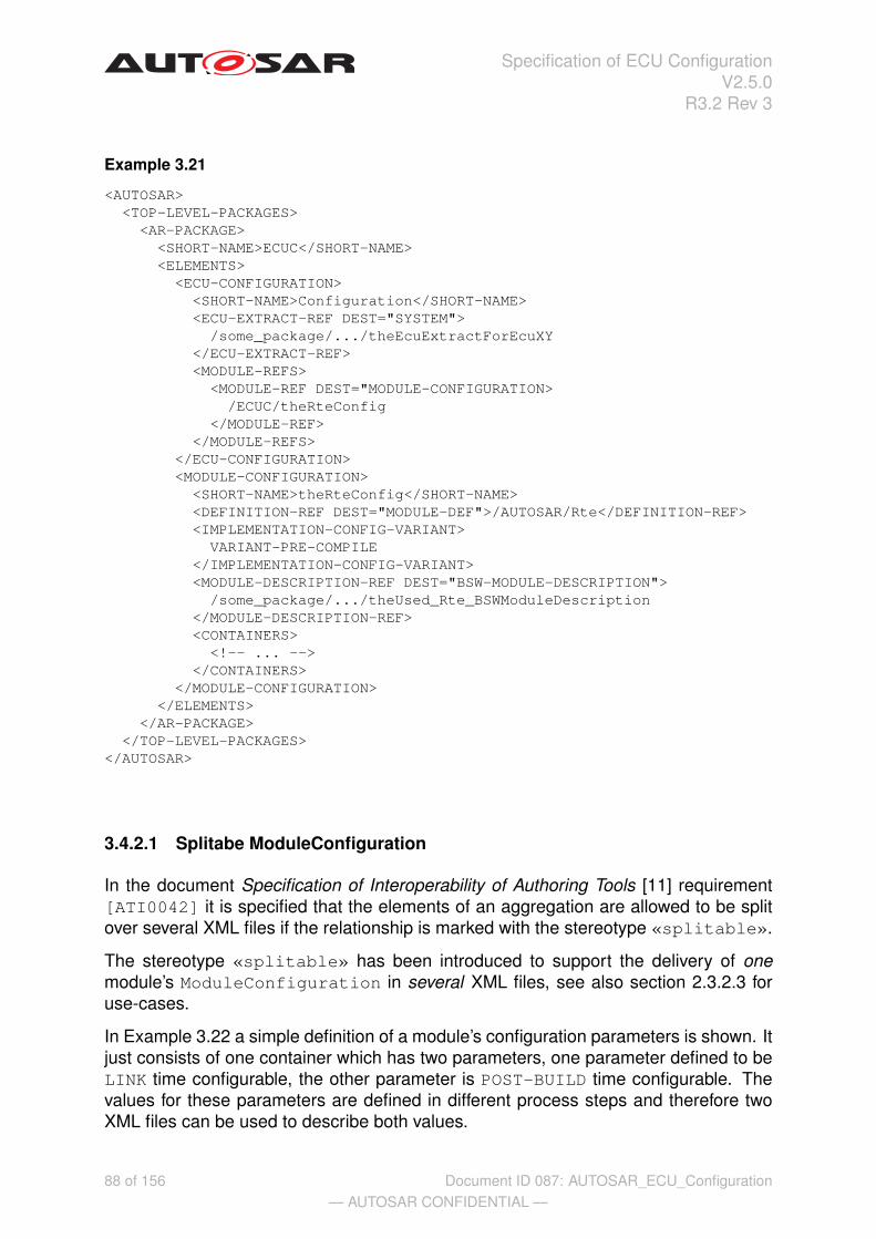
Specification of ECU ConfigurationV2.5.0
R3.2 Rev 3
Example 3.21
<AUTOSAR><TOP-LEVEL-PACKAGES>
<AR-PACKAGE><SHORT-NAME>ECUC</SHORT-NAME><ELEMENTS>
<ECU-CONFIGURATION><SHORT-NAME>Configuration</SHORT-NAME><ECU-EXTRACT-REF DEST="SYSTEM">
/some_package/.../theEcuExtractForEcuXY</ECU-EXTRACT-REF><MODULE-REFS>
<MODULE-REF DEST="MODULE-CONFIGURATION>/ECUC/theRteConfig
</MODULE-REF></MODULE-REFS>
</ECU-CONFIGURATION><MODULE-CONFIGURATION>
<SHORT-NAME>theRteConfig</SHORT-NAME><DEFINITION-REF DEST="MODULE-DEF">/AUTOSAR/Rte</DEFINITION-REF><IMPLEMENTATION-CONFIG-VARIANT>
VARIANT-PRE-COMPILE</IMPLEMENTATION-CONFIG-VARIANT><MODULE-DESCRIPTION-REF DEST="BSW-MODULE-DESCRIPTION">
/some_package/.../theUsed_Rte_BSWModuleDescription</MODULE-DESCRIPTION-REF><CONTAINERS>
<!-- ... --></CONTAINERS>
</MODULE-CONFIGURATION></ELEMENTS>
</AR-PACKAGE></TOP-LEVEL-PACKAGES>
</AUTOSAR>
3.4.2.1 Splitabe ModuleConfiguration
In the document Specification of Interoperability of Authoring Tools [11] requirement[ATI0042] it is specified that the elements of an aggregation are allowed to be splitover several XML files if the relationship is marked with the stereotype «splitable».
The stereotype «splitable» has been introduced to support the delivery of onemodule’s ModuleConfiguration in several XML files, see also section 2.3.2.3 foruse-cases.
In Example 3.22 a simple definition of a module’s configuration parameters is shown. Itjust consists of one container which has two parameters, one parameter defined to beLINK time configurable, the other parameter is POST-BUILD time configurable. Thevalues for these parameters are defined in different process steps and therefore twoXML files can be used to describe both values.
88 of 156— AUTOSAR CONFIDENTIAL —
Document ID 087: AUTOSAR_ECU_Configuration

Specification of ECU ConfigurationV2.5.0
R3.2 Rev 3
In example 3.23 the value for the LINK time parameter SignalSize is specified, whilein exmaple 3.24 the POST-BUILD parameter’s BitPosition value is given.
The XML structure in both ModuleConfiguration XML files is equivalent with respect tothe packages and containers. In both XML files a container with the name theSignalis defined. It is up to the configuration tool to merge the content of these two files intoone model. Also is the number of possible XML files not limited, so it would be possible(although probably not reasonable) to put each parameter value into one XML file.
Example 3.22
...<MODULE-DEF>
<SHORT-NAME>Com</SHORT-NAME><LOWER-MULTIPLICITY>0</LOWER-MULTIPLICITY><UPPER-MULTIPLICITY>1</UPPER-MULTIPLICITY>
<IMPLEMENTATION-CONFIG-VARIANT>Variant3</IMPLEMENTATION-CONFIG-VARIANT><CONTAINERS>
<PARAM-CONF-CONTAINER-DEF><SHORT-NAME>ComSignal</SHORT-NAME><LOWER-MULTIPLICITY>0</LOWER-MULTIPLICITY><UPPER-MULTIPLICITY>*</UPPER-MULTIPLICITY>
<MULTIPLE-CONFIGURATION-CONTAINER>false</MULTIPLE-CONFIGURATION-CONTAINER><PARAMETERS>
<INTEGER-PARAM-DEF><SHORT-NAME>SignalSize</SHORT-NAME>
<IMPLEMENTATION-CONFIG-CLASS>LINK</IMPLEMENTATION-CONFIG-CLASS><ORIGIN>AUTOSAR_ECUC</ORIGIN>
</INTEGER-PARAM-DEF><INTEGER-PARAM-DEF>
<SHORT-NAME>BitPosition</SHORT-NAME><IMPLEMENTATION-CONFIG-CLASS>POST-BUILD</IMPLEMENTATION-CONFIG-CLASS>
<ORIGIN>AUTOSAR_ECUC</ORIGIN></INTEGER-PARAM-DEF>
</PARAMETERS></PARAM-CONF-CONTAINER-DEF>
</CONTAINERS></MODULE-DEF>
...
89 of 156— AUTOSAR CONFIDENTIAL —
Document ID 087: AUTOSAR_ECU_Configuration

Specification of ECU ConfigurationV2.5.0
R3.2 Rev 3
Example 3.23
<AUTOSAR><TOP-LEVEL-PACKAGES>
<AR-PACKAGE><SHORT-NAME>ECUC</SHORT-NAME><ELEMENTS>
<MODULE-CONFIGURATION><SHORT-NAME>theComConfig</SHORT-NAME><DEFINITION-REF DEST="MODULE-DEF">/Vendor/Com</DEFINITION-REF><MODULE-DESCRIPTION-REF DEST="BSW-MODULE-DESCRIPTION">
/some_package/some_path/theUsed_Com_BSWModuleDescription</MODULE-DESCRIPTION-REF><CONTAINERS>
<CONTAINER><SHORT-NAME>theSignal</SHORT-NAME><DEFINITION-REF DEST="PARAM-CONF-CONTAINER-DEF">
/Vendor/Com/ComSignal</DEFINITION-REF><PARAMETER-VALUES>
<INTEGER-VALUE><DEFINITION-REF DEST="INTEGER-PARAM-DEF">
/Vendor/Com/ComSignal/SignalSize</DEFINITION-REF><VALUE>8</VALUE>
</INTEGER-VALUE></PARAMETER-VALUES>
</CONTAINER></CONTAINERS>
</MODULE-CONFIGURATION></ELEMENTS>
</AR-PACKAGE></TOP-LEVEL-PACKAGES>
</AUTOSAR>
90 of 156— AUTOSAR CONFIDENTIAL —
Document ID 087: AUTOSAR_ECU_Configuration
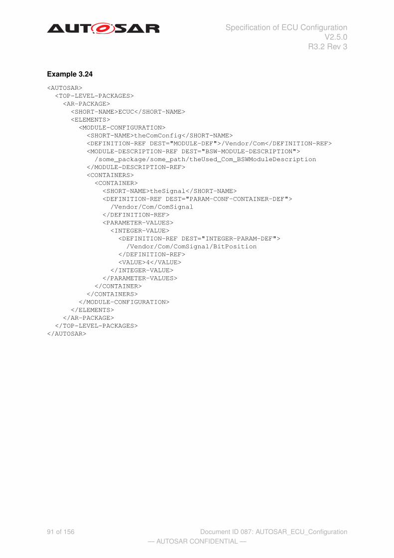
Specification of ECU ConfigurationV2.5.0
R3.2 Rev 3
Example 3.24
<AUTOSAR><TOP-LEVEL-PACKAGES>
<AR-PACKAGE><SHORT-NAME>ECUC</SHORT-NAME><ELEMENTS>
<MODULE-CONFIGURATION><SHORT-NAME>theComConfig</SHORT-NAME><DEFINITION-REF DEST="MODULE-DEF">/Vendor/Com</DEFINITION-REF><MODULE-DESCRIPTION-REF DEST="BSW-MODULE-DESCRIPTION">
/some_package/some_path/theUsed_Com_BSWModuleDescription</MODULE-DESCRIPTION-REF><CONTAINERS>
<CONTAINER><SHORT-NAME>theSignal</SHORT-NAME><DEFINITION-REF DEST="PARAM-CONF-CONTAINER-DEF">
/Vendor/Com/ComSignal</DEFINITION-REF><PARAMETER-VALUES>
<INTEGER-VALUE><DEFINITION-REF DEST="INTEGER-PARAM-DEF">
/Vendor/Com/ComSignal/BitPosition</DEFINITION-REF><VALUE>4</VALUE>
</INTEGER-VALUE></PARAMETER-VALUES>
</CONTAINER></CONTAINERS>
</MODULE-CONFIGURATION></ELEMENTS>
</AR-PACKAGE></TOP-LEVEL-PACKAGES>
</AUTOSAR>
91 of 156— AUTOSAR CONFIDENTIAL —
Document ID 087: AUTOSAR_ECU_Configuration

Specification of ECU ConfigurationV2.5.0
R3.2 Rev 3
3.4.3 Parameter Container Description
Symmetrically to the parameter container definition (see section 3.3.3) the parame-ter container description is specified to group other containers, parameter values andreferences. Figure 3.22 depicts the general structure of the configuration containerdescription and its association to the configuration definition. The dependencies re-flect the direct relationship between a Container and a ContainerDef as well as aParameterValue and a ParameterType.
Identifiable
Container
ParameterValueCommonConfigurationAttributes
ConfigParameter
+ symbolicNameValue :Boolean
ParamConfContainerDef
+ multipleConfigurationContainer :Boolean
IdentifiableParamConfMultipl icity
ContainerDef
+ postBuildChangeable :Boolean
ChoiceContainerDef
+parameterValue *«splitable»
+subContainer *
«spli table»
0..1
+parameter *
+subContainer *
+choice
*
«splitable»
+definition
1
+definition
1
Figure 3.22: Parameter container description
[ecuc_sws_3012] The Container inherits from Identifiable defining a name-space for all Container, ParameterValue and ReferenceValue that belong tothat Container.
[ecuc_sws_3019] The reference definition assigns the Container to the accord-ing ContainerDef17 it is depending on.
If the configuration description would be provided without an according configurationdefinition an editor could not reconstruct what kind of ContainerDef a Containeris based upon.
[ecuc_sws_3011] If a ContainerDef has specified a lowerMultiplicity < 1the corresponding Container may be omitted in the ECU Configuration Descriptionbecause of being treated as optional.
17including all ContainerDef’s decendants
92 of 156— AUTOSAR CONFIDENTIAL —
Document ID 087: AUTOSAR_ECU_Configuration

Specification of ECU ConfigurationV2.5.0
R3.2 Rev 3
Class ContainerPackage M2::AUTOSARTemplates::ECUCDescriptionTemplateNote Represents a Container definition in the ECU Configuration Description.Base ARObject,IdentifiableAttribute Datatype Mul. Kind Notedefinition ContainerDef 1 ref Reference to the definition of this Container in the
ECU Configuration Parameter Definition.
Stereotypes: atpSplitableTags: xml.sequenceOffset=-10
parameterValue
ParameterValue * aggr Aggregates all ECU Configuration Values withinthis Container.
Stereotypes: atpSplitablereferenceValue
ConfigReferenceValue
* aggr Aggregates all References with this container.
Stereotypes: atpSplitablesubContainer
Container * aggr Aggregates all sub-containers within thiscontainer.
Stereotypes: atpSplitable
Table 3.31: Container
[ecuc_sws_2092] If a ParamConfContainerDef is specified to be the multiple-ConfigurationContainer there can be several Container elements defined inthe ECU Configuration. Each Container shortName does specify the name of theconfiguration set it contains.
The multipleConfigurationContainer is further detailed in section 3.4.7.
In example 3.25 a snippet of an ECU Configuration Description XML file is shown thatconforms to the ECU Configuration Parameter Definition described in example 3.4.The container RteGeneration is specified to have an upperMultiplicity of 1, sothere can only be one Container representation. The container SwComponentIn-stance has an upperMultiplicity of *, so there can be several representationsof this Container.
93 of 156— AUTOSAR CONFIDENTIAL —
Document ID 087: AUTOSAR_ECU_Configuration

Specification of ECU ConfigurationV2.5.0
R3.2 Rev 3
Example 3.25
...<MODULE-CONFIGURATION>
<SHORT-NAME>theRteConfig</SHORT-NAME><DEFINITION-REF DEST="MODULE-DEF">/AUTOSAR/Rte</DEFINITION-REF><MODULE-DESCRIPTION-REF DEST="BSW-MODULE-DESCRIPTION">
/some_package/some_path/theUsed_Rte_BSWModuleDescription</MODULE-DESCRIPTION-REF><CONTAINERS>
<CONTAINER><SHORT-NAME>theGeneration</SHORT-NAME><DEFINITION-REF DEST="PARAM-CONF-CONTAINER-DEF">
/AUTOSAR/Rte/RteGeneration</DEFINITION-REF><SUB-CONTAINERS>
<!-- ... --></SUB-CONTAINERS>
</CONTAINER><CONTAINER>
<SHORT-NAME>SwcInstance1</SHORT-NAME><DEFINITION-REF DEST="PARAM-CONF-CONTAINER-DEF">
/AUTOSAR/Rte/SwComponentInstance</DEFINITION-REF><SUB-CONTAINERS>
<!-- ... --></SUB-CONTAINERS>
</CONTAINER><CONTAINER>
<SHORT-NAME>SwcInstance2</SHORT-NAME><DEFINITION-REF DEST="PARAM-CONF-CONTAINER-DEF">
/AUTOSAR/Rte/SwComponentInstance</DEFINITION-REF><SUB-CONTAINERS>
<!-- ... --></SUB-CONTAINERS>
</CONTAINER></CONTAINERS>
</MODULE-CONFIGURATION>...
94 of 156— AUTOSAR CONFIDENTIAL —
Document ID 087: AUTOSAR_ECU_Configuration

Specification of ECU ConfigurationV2.5.0
R3.2 Rev 3
3.4.3.1 Choice Containers
[ecuc_sws_3020] In the ECU Configuration Parameter Definition the containerchoices are specified as part of the ChoiceContainerDef. On the description sidea ChoiceContainerDef is treated as a usual container, though it depends on theupperMultiplicity of the ChoiceContainerDef how often the choice can betaken. Which choice has been taken is defined by the <DEFINITION-REF> of the<SUB-CONTAINER>.
Example 3.26 depicts the notation of a filled out ChoiceContainerDef as describedin example 3.5.
Example 3.26
...<CONTAINER>
<SHORT-NAME>OsAlarm</SHORT-NAME><DEFINITION-REF DEST="PARAM-CONF-CONTAINER-DEF">
/AUTOSAR/Os/OsApplication/OsAlarm</DEFINITION-REF><SUB-CONTAINERS>
<CONTAINER><SHORT-NAME>myOsAlarmAction</SHORT-NAME><DEFINITION-REF DEST="PARAM-CONF-CONTAINER-DEF">
/AUTOSAR/Os/OsApplication/OsAlarm/OsAlarmAction</DEFINITION-REF><SUB-CONTAINERS>
<CONTAINER><SHORT-NAME>myTaskActivation</SHORT-NAME><DEFINITION-REF DEST="PARAM-CONF-CONTAINER-DEF">
/AUTOSAR/Os/OsApplication/OsAlarm/OsAlarmAction/OsAlarmActivateTask</DEFINITION-REF><!--...-->
</CONTAINER></SUB-CONTAINERS>
</CONTAINER></SUB-CONTAINERS>
</CONTAINER>...
95 of 156— AUTOSAR CONFIDENTIAL —
Document ID 087: AUTOSAR_ECU_Configuration
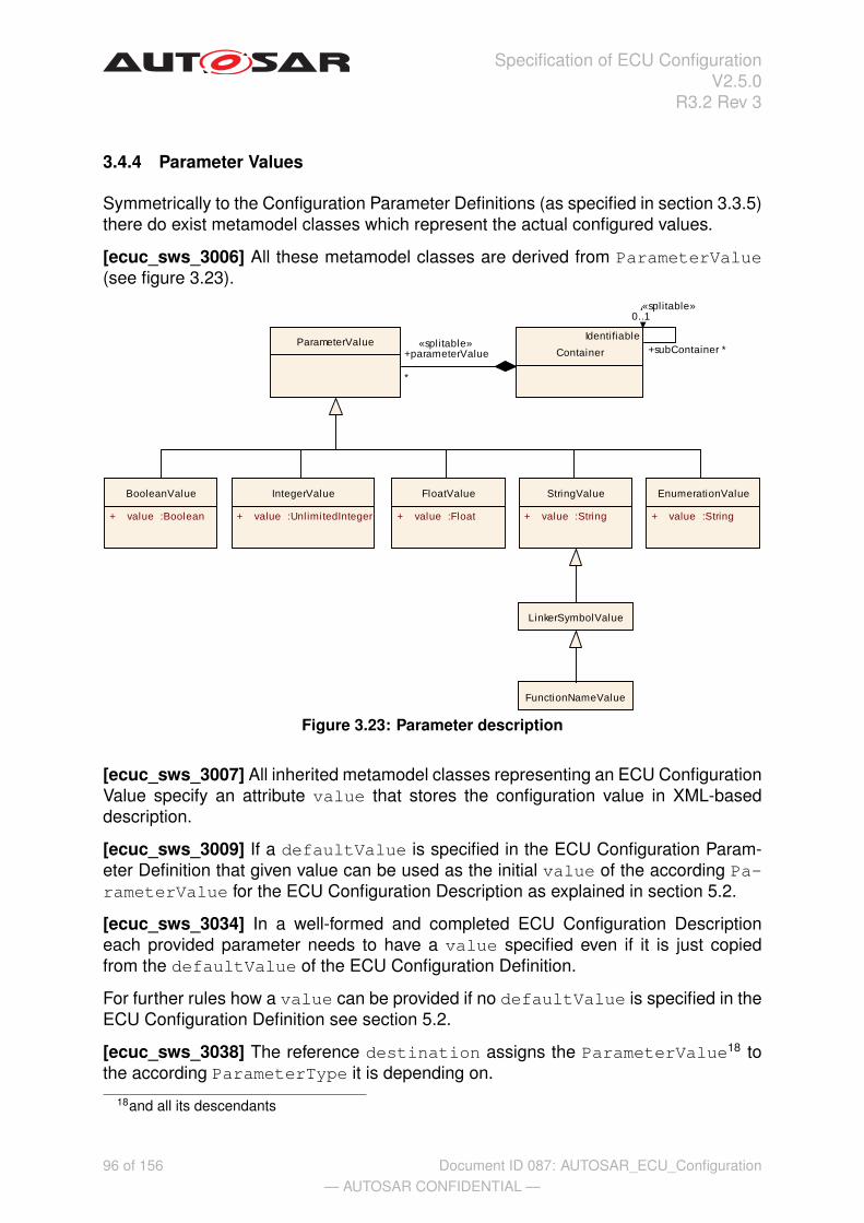
Specification of ECU ConfigurationV2.5.0
R3.2 Rev 3
3.4.4 Parameter Values
Symmetrically to the Configuration Parameter Definitions (as specified in section 3.3.5)there do exist metamodel classes which represent the actual configured values.
[ecuc_sws_3006] All these metamodel classes are derived from ParameterValue(see figure 3.23).
Identifiable
Container
IntegerValue
+ value :UnlimitedInteger
ParameterValue
FloatValue
+ value :Float
BooleanValue
+ value :Boolean
StringValue
+ value :String
EnumerationValue
+ value :String
FunctionNameValue
LinkerSymbolValue
+parameterValue
*
«splitable»+subContainer *
«splitable»0..1
Figure 3.23: Parameter description
[ecuc_sws_3007] All inherited metamodel classes representing an ECU ConfigurationValue specify an attribute value that stores the configuration value in XML-baseddescription.
[ecuc_sws_3009] If a defaultValue is specified in the ECU Configuration Param-eter Definition that given value can be used as the initial value of the according Pa-rameterValue for the ECU Configuration Description as explained in section 5.2.
[ecuc_sws_3034] In a well-formed and completed ECU Configuration Descriptioneach provided parameter needs to have a value specified even if it is just copiedfrom the defaultValue of the ECU Configuration Definition.
For further rules how a value can be provided if no defaultValue is specified in theECU Configuration Definition see section 5.2.
[ecuc_sws_3038] The reference destination assigns the ParameterValue18 tothe according ParameterType it is depending on.
18and all its descendants
96 of 156— AUTOSAR CONFIDENTIAL —
Document ID 087: AUTOSAR_ECU_Configuration

Specification of ECU ConfigurationV2.5.0
R3.2 Rev 3
[ecuc_sws_3010] If an ECU Configuration Parameter has specified a lowerMulti-plicity < 1 an ECU Configuration Value may be omitted in the ECU ConfigurationDescription because of being treated as optional.
Class ParameterValue (abstract)Package M2::AUTOSARTemplates::ECUCDescriptionTemplateNote Common class to all types of configuration valuesBase ARObjectAttribute Datatype Mul. Kind Notedefinition ConfigParamete
r1 ref Reference to the definition of this ParameterValue
subclasses in the ECU Configuration ParameterDefinition.
Tags: xml.sequenceOffset=-10
Table 3.32: ParameterValue
All specialized parameter values that are derived from ParameterValue are de-scribed in the sections below. The used examples represent configuration values thatcorrespond to their appropriate parameter definition examples depicted in figure 3.11and their XML representation.
3.4.4.1 Boolean Values
[ecuc_sws_3000] A BooleanValue stores a configuration value that is of definitiontype BooleanParamDef.
Class BooleanValuePackage M2::AUTOSARTemplates::ECUCDescriptionTemplateNote Representing a configuration value of definition type BooleanParamDefBase ARObject,ParameterValueAttribute Datatype Mul. Kind Notevalue Boolean 1 attr Stores the value of the Boolean parameter.
Table 3.33: BooleanValue
97 of 156— AUTOSAR CONFIDENTIAL —
Document ID 087: AUTOSAR_ECU_Configuration

Specification of ECU ConfigurationV2.5.0
R3.2 Rev 3
Example 3.27 depicts the configuration description of definition type BooleanParam-Def for example 3.9.
Example 3.27
...<BOOLEAN-VALUE>
<DEFINITION-REF DEST="BOOLEAN-PARAM-DEF">/AUTOSAR/Rte/RteGeneration/RTE_DEV_ERROR_DETECT
</DEFINITION-REF><VALUE>true</VALUE>
</BOOLEAN-VALUE>...
3.4.4.2 Integer Values
[ecuc_sws_3001] An IntegerValue stores a configuration value that is of definitiontype IntegerParamDef.
[ecuc_sws_3040] The value has to be specified in signed decimal notation withoutdecimal point.
Class IntegerValuePackage M2::AUTOSARTemplates::ECUCDescriptionTemplateNote Representing a configuration value of definition type IntegerParamDefBase ARObject,ParameterValueAttribute Datatype Mul. Kind Notevalue UnlimitedInteger 1 attr Stores the value of the Integer parameter.
Table 3.34: IntegerValue
Example 3.28 depicts the configuration description of definition type IntegerParam-Def for example 3.10.
Example 3.28
...<INTEGER-VALUE>
<DEFINITION-REF DEST="INTEGER-PARAM-DEF">/AUTOSAR/Rte/RunnableEntityMapping/PositionInTask
</DEFINITION-REF><VALUE>5</VALUE>
</INTEGER-VALUE>...
98 of 156— AUTOSAR CONFIDENTIAL —
Document ID 087: AUTOSAR_ECU_Configuration

Specification of ECU ConfigurationV2.5.0
R3.2 Rev 3
3.4.4.3 Float Values
[ecuc_sws_3002] A FloatValue stores a configuration value that is of definition typeFloatParamDef.
Class FloatValuePackage M2::AUTOSARTemplates::ECUCDescriptionTemplateNote Representing a configuration value of definition type FloatParamDefBase ARObject,ParameterValueAttribute Datatype Mul. Kind Notevalue Float 1 attr Stores the value of the Float parameter.
Table 3.35: FloatValue
Example 3.29 depicts the configuration description of definition type FloatParamDeffor example 3.11.
Example 3.29
...<FLOAT-VALUE>
<DEFINITION-REF DEST="FLOAT-PARAM-DEF">/AUTOSAR/Rte/RunnableEntityMapping/SchedulingPeriod
</DEFINITION-REF><VALUE>74.8</VALUE>
</FLOAT-VALUE>...
3.4.4.4 String Values
[ecuc_sws_3003] A StringValue stores a configuration value that is of definitiontype StringParamDef.
Class StringValuePackage M2::AUTOSARTemplates::ECUCDescriptionTemplateNote Representing a configuration value of definition type StringParamDefBase ARObject,ParameterValueAttribute Datatype Mul. Kind Notevalue String 1 attr Stores the value of the String parameter.
Table 3.36: StringValue
3.4.4.5 Linker Symbol Values
[ecuc_sws_3041] A LinkerSymbolValue stores a configuration value that is of def-inition type LinkerSymbolParameter.
99 of 156— AUTOSAR CONFIDENTIAL —
Document ID 087: AUTOSAR_ECU_Configuration

Specification of ECU ConfigurationV2.5.0
R3.2 Rev 3
Class LinkerSymbolValuePackage M2::AUTOSARTemplates::ECUCDescriptionTemplateNote Representing a configuration value of definition type LinkerSymbolDefBase ARObject,ParameterValue,StringValueAttribute Datatype Mul. Kind Note
Table 3.37: LinkerSymbolValue
Example 3.30 depicts the configuration description of definition type LinkerSymbol-Def for example 3.12.
Example 3.30
...<LINKER-SYMBOL-VALUE>
<DEFINITION-REF DEST="LINKER-SYMBOL-DEF">/AUTOSAR/Rte/Resource/Pim/RtePimInitializationSymbol
</DEFINITION-REF><VALUE>MyPimInitValuesLightMaster</VALUE>
</LINKER-SYMBOL-VALUE>...
3.4.4.6 Function Name Values
[ecuc_sws_3005] A FunctionNameValue stores a configuration value that is of def-inition type FunctionNameParamDef.
Class FunctionNameValuePackage M2::AUTOSARTemplates::ECUCDescriptionTemplateNote Representing a configuration value of definition type FunctionNameDefBase ARObject,LinkerSymbolValue,ParameterValue,StringValueAttribute Datatype Mul. Kind Note
Table 3.38: FunctionNameValue
100 of 156— AUTOSAR CONFIDENTIAL —
Document ID 087: AUTOSAR_ECU_Configuration

Specification of ECU ConfigurationV2.5.0
R3.2 Rev 3
Example 3.31 depicts the configuration description of definition type FunctionName-Def for example 3.13.
Example 3.31
...<FUNCTION-NAME-VALUE>
<DEFINITION-REF DEST="FUNCTION-NAME-DEF">/AUTOSAR/Eep/EepInitConfiguration/EepJobEndNotification
</DEFINITION-REF><VALUE>Eep_VendorXY_JobEndNotification</VALUE>
</FUNCTION-NAME-VALUE>...
3.4.4.7 Enumeration Values
[ecuc_sws_3048] A EnumerationValue stores a configuration value that is of defi-nition type EnumerationParamDef.
Class EnumerationValuePackage M2::AUTOSARTemplates::ECUCDescriptionTemplateNote Representing a configuration value of definition type EnumerationParamDefBase ARObject,ParameterValueAttribute Datatype Mul. Kind Notevalue String 1 attr Stores the chosen literal.
Table 3.39: EnumerationValue
Example 3.32 depicts the configuration description of definition type Enumeration-ParamDef for example 3.14.
Example 3.32
...<ENUMERATION-VALUE>
<DEFINITION-REF DEST="ENUMERATION-PARAM-DEF">/AUTOSAR/Rte/RteGeneration/RteGenerationMode
</DEFINITION-REF><VALUE>CompatibilityMode</VALUE>
</ENUMERATION-VALUE>...
101 of 156— AUTOSAR CONFIDENTIAL —
Document ID 087: AUTOSAR_ECU_Configuration
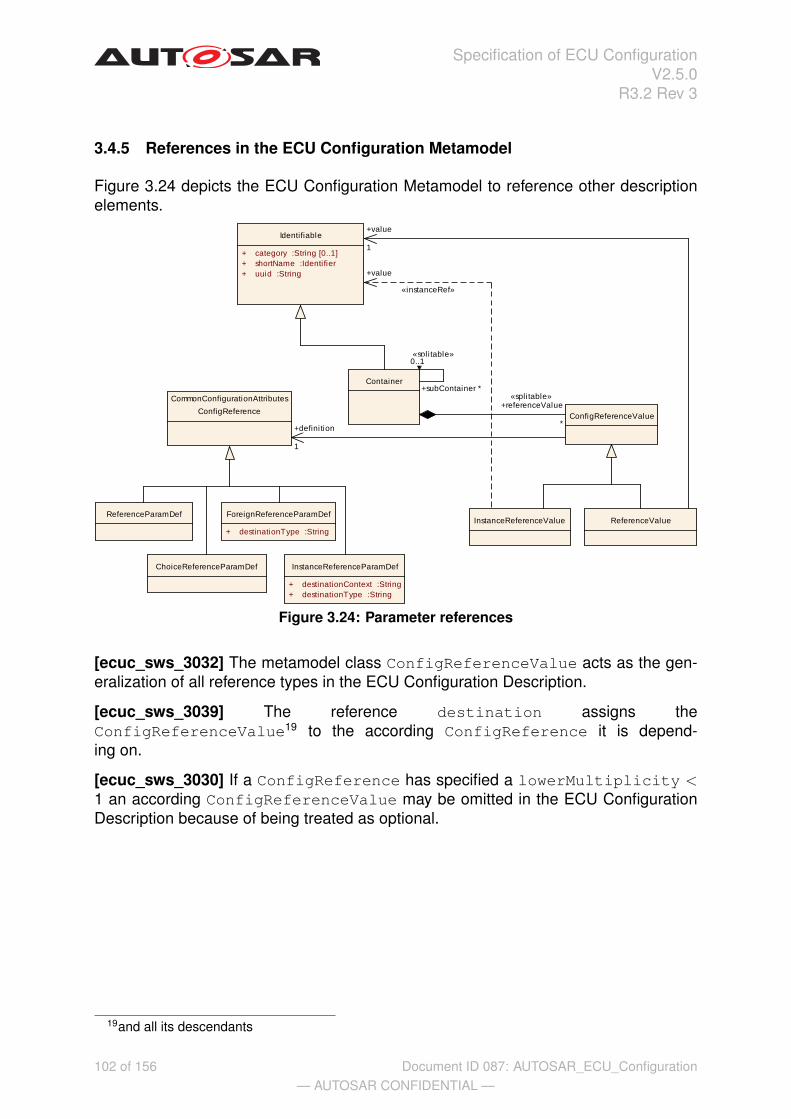
Specification of ECU ConfigurationV2.5.0
R3.2 Rev 3
3.4.5 References in the ECU Configuration Metamodel
Figure 3.24 depicts the ECU Configuration Metamodel to reference other descriptionelements.
ReferenceValue
CommonConfigurationAttributes
ConfigReference
ChoiceReferenceParamDef InstanceReferenceParamDef
+ destinationContext :String+ destinationType :String
ReferenceParamDef
Identifiable
+ category :String [0..1]+ shortName :Identifier+ uuid :String
Container
ForeignReferenceParamDef
+ destinationType :String
ConfigReferenceValue
InstanceReferenceValue
+definition
1
+subContainer *
«spli table»0..1
+referenceValue
*
«splitable»
+value
1
«instanceRef»
+value
Figure 3.24: Parameter references
[ecuc_sws_3032] The metamodel class ConfigReferenceValue acts as the gen-eralization of all reference types in the ECU Configuration Description.
[ecuc_sws_3039] The reference destination assigns theConfigReferenceValue19 to the according ConfigReference it is depend-ing on.
[ecuc_sws_3030] If a ConfigReference has specified a lowerMultiplicity <1 an according ConfigReferenceValue may be omitted in the ECU ConfigurationDescription because of being treated as optional.
19and all its descendants
102 of 156— AUTOSAR CONFIDENTIAL —
Document ID 087: AUTOSAR_ECU_Configuration

Specification of ECU ConfigurationV2.5.0
R3.2 Rev 3
Class ConfigReferenceValue (abstract)Package M2::AUTOSARTemplates::ECUCDescriptionTemplateNote Abstract class to be used as common parent for all reference values in the ECU
Configuration Description.Base ARObjectAttribute Datatype Mul. Kind Notedefinition ConfigReferenc
e1 ref Reference to the definition of this
ConfigReferenceValue subclasses in the ECUConfiguration Parameter Definition.
Tags: xml.sequenceOffset=-10
Table 3.40: ConfigReferenceValue
[ecuc_sws_3027] The metamodel class ReferenceValue provides the mechanismto reference to any model element of type Identifiable.
[ecuc_sws_3028] Therefore this class provides the means to describe all kinds ofreference definitions except an InstanceReferenceParamDef, which is describedin section 3.4.5.1 in more detail.
[ecuc_sws_3029] A ChoiceReferenceParamDef translates to a Re-ferenceValue in the ECU Configuration Description because the choice hasto be resolved in that description. Therefore no special configuration description typeis introduced.
Class ReferenceValuePackage M2::AUTOSARTemplates::ECUCDescriptionTemplateNote Used to represent a configuration value that has a parameter definition of type
ConfigReference (used for all of its specializations excludingInstanceReferenceParamDef).
Base ARObject,ConfigReferenceValueAttribute Datatype Mul. Kind Notevalue Identifiable 1 ref Specifes the destination of the reference.
Table 3.41: ReferenceValue
[ecuc_sws_2093] If a ConfigReferenceValue references a container within someModuleConfiguration the referenced container shall be part of a ModuleConfig-uration which is itself part of the EcuConfiguration.
According to figure 3.20 a ModuleConfiguration is part of the EcuConfigura-tion if it is referenced with the module role.
The following examples will picture that ReferenceValue can be used to representmost of the specializations of ConfigReference (namely ReferenceParamDef,ChoiceReferenceParamDef, ForeignReferenceParamDef and Symbolic-NameReferenceParamDef).
103 of 156— AUTOSAR CONFIDENTIAL —
Document ID 087: AUTOSAR_ECU_Configuration

Specification of ECU ConfigurationV2.5.0
R3.2 Rev 3
Example 3.33 depicts the configuration description of definition type Referen-ceParamDef for example 3.15.
Example 3.33
...<CONTAINER>
<SHORT-NAME>myOsApplication</SHORT-NAME><DEFINITION-REF DEST="PARAM-CONF-CONTAINER-DEF">
/AUTOSAR/Os/OsApplication</DEFINITION-REF><REFERENCE-VALUES>
<REFERENCE-VALUE><DEFINITION-REF DEST="REFERENCE-PARAM-DEF">
/AUTOSAR/Os/OsApplication/OsAppScheduleTableRef</DEFINITION-REF><VALUE-REF DEST="PARAM-CONF-CONTAINER-DEF">
/ECUC/myOs/myOsScheduleTable1</VALUE-REF>
</REFERENCE-VALUE></REFERENCE-VALUES>
</CONTAINER>...
Example 3.34 depicts the configuration description of definition type ChoiceRefer-enceParamDef for example 3.16. To illustrate the usage of a ChoiceReferen-ceParamDef in more detail, this example takes advantage of the fact that a PortPinmay be used in several modes at once. Therefore it has multiple references of differenttype.
104 of 156— AUTOSAR CONFIDENTIAL —
Document ID 087: AUTOSAR_ECU_Configuration
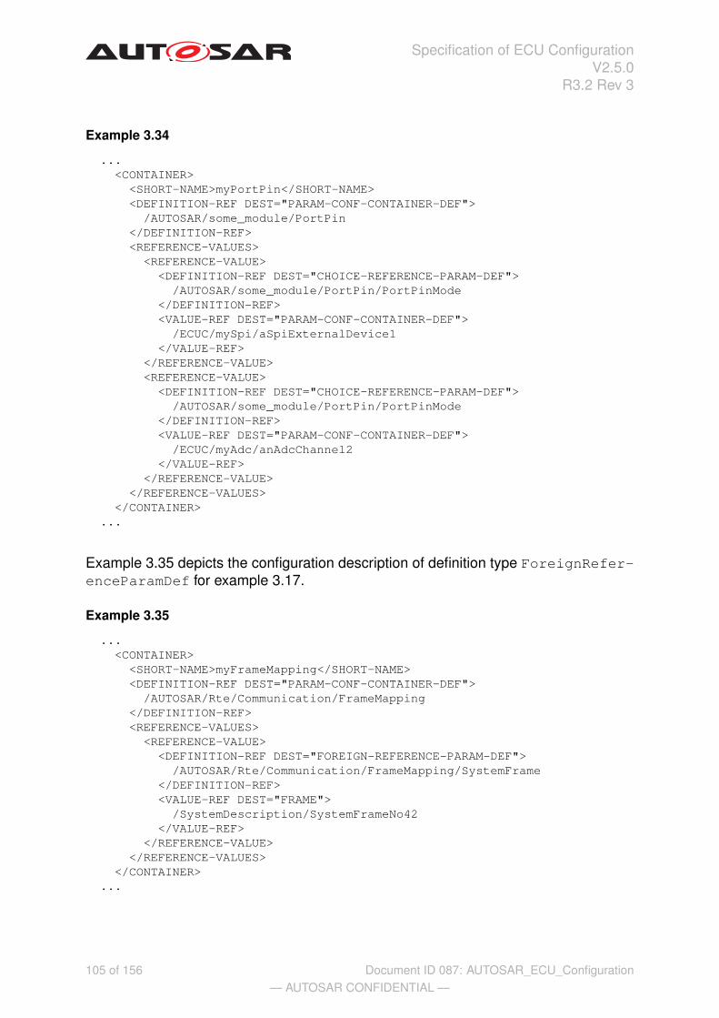
Specification of ECU ConfigurationV2.5.0
R3.2 Rev 3
Example 3.34
...<CONTAINER>
<SHORT-NAME>myPortPin</SHORT-NAME><DEFINITION-REF DEST="PARAM-CONF-CONTAINER-DEF">
/AUTOSAR/some_module/PortPin</DEFINITION-REF><REFERENCE-VALUES>
<REFERENCE-VALUE><DEFINITION-REF DEST="CHOICE-REFERENCE-PARAM-DEF">
/AUTOSAR/some_module/PortPin/PortPinMode</DEFINITION-REF><VALUE-REF DEST="PARAM-CONF-CONTAINER-DEF">
/ECUC/mySpi/aSpiExternalDevice1</VALUE-REF>
</REFERENCE-VALUE><REFERENCE-VALUE>
<DEFINITION-REF DEST="CHOICE-REFERENCE-PARAM-DEF">/AUTOSAR/some_module/PortPin/PortPinMode
</DEFINITION-REF><VALUE-REF DEST="PARAM-CONF-CONTAINER-DEF">
/ECUC/myAdc/anAdcChannel2</VALUE-REF>
</REFERENCE-VALUE></REFERENCE-VALUES>
</CONTAINER>...
Example 3.35 depicts the configuration description of definition type ForeignRefer-enceParamDef for example 3.17.
Example 3.35
...<CONTAINER>
<SHORT-NAME>myFrameMapping</SHORT-NAME><DEFINITION-REF DEST="PARAM-CONF-CONTAINER-DEF">
/AUTOSAR/Rte/Communication/FrameMapping</DEFINITION-REF><REFERENCE-VALUES>
<REFERENCE-VALUE><DEFINITION-REF DEST="FOREIGN-REFERENCE-PARAM-DEF">
/AUTOSAR/Rte/Communication/FrameMapping/SystemFrame</DEFINITION-REF><VALUE-REF DEST="FRAME">
/SystemDescription/SystemFrameNo42</VALUE-REF>
</REFERENCE-VALUE></REFERENCE-VALUES>
</CONTAINER>...
105 of 156— AUTOSAR CONFIDENTIAL —
Document ID 087: AUTOSAR_ECU_Configuration

Specification of ECU ConfigurationV2.5.0
R3.2 Rev 3
3.4.5.1 Instance Reference Values
Due to the formalization of prototypes in the AUTOSAR Templates (see [12]) the refer-ence to the instance of a prototype needs to declare the complete context in which theinstance is residing.
[ecuc_sws_3033] The metamodel class InstanceReferenceValue provides themechanism to reference to an actual instance of a prototype. This is achieved byspecifying a relation with the stereotype <<instanceRef>>.
In figure 3.25 the detailed modeling of the InstanceReferenceValue<<instanceRef>> is specified.
ConfigReferenceValue
ECUCDescriptionTemplate::InstanceReferenceValue
Identifiable::Identifiable
+ category :String [0..1]+ shortName :Identifier+ uuid :String
«instanceRef»InstanceReferenceValue_value
«instanceRef»
+value
«instanceRef.target»
+value
«instanceRef.context»
+context
*
+value
Figure 3.25: Instance Reference Value details
Class InstanceReferenceValuePackage M2::AUTOSARTemplates::ECUCDescriptionTemplateNote InstanceReference representation in the ECU Configuration.Base ARObject,ConfigReferenceValueAttribute Datatype Mul. Kind Notevalue Identifiable 1 iref InstanceReference representation in the ECU
Configuration.
Table 3.42: InstanceReferenceValue
Example 3.36 depicts the configuration description of definition type InstanceRef-erenceParamDef for example 3.18. As one can see in the example the referencevalue is decomposed of the context path of the instance and the reference to the in-stance itself.
106 of 156— AUTOSAR CONFIDENTIAL —
Document ID 087: AUTOSAR_ECU_Configuration

Specification of ECU ConfigurationV2.5.0
R3.2 Rev 3
Example 3.36
...<CONTAINER>
<SHORT-NAME>mySenderReceiverMapping</SHORT-NAME><DEFINITION-REF DEST="PARAM-CONF-CONTAINER-DEF">
/AUTOSAR/Rte/DataMappings/DataSRMapping</DEFINITION-REF><REFERENCE-VALUES>
<INSTANCE-REFERENCE-VALUE><DEFINITION-REF DEST="INSTANCE-REFERENCE-PARAM-DEF">
/AUTOSAR/Rte/DataMappings/DataSRMapping/DataElementPrototypeRef</DEFINITION-REF><VALUE-IREF>
<CONTEXT-REF DEST="COMPONENT-PROTOTYPE">/DoorFR
</CONTEXT-REF><CONTEXT-REF DEST="R-PORT-PROTOTYPE">
/DoorAntennaReceiver</CONTEXT-REF><VALUE-REF DEST="DATA-ELEMENT-PROTOTYPE">
/AntennaStatus</VALUE-REF>
</VALUE-IREF></INSTANCE-REFERENCE-VALUE>
</REFERENCE-VALUES></CONTAINER>
...
3.4.5.2 Representation of Symbolic Names
[ecuc_sws_3036] A SymbolicNameReferenceParamDef is represented by anusual ReferenceValue in the ECU Configuration Description.
[ecuc_sws_3037] The shortName of the referenced destination is expected to bethe provided symbolic name in the implementation later on. Therefore the code gener-ator of the providing module has the responsibility to associate the provided symbolicname20 to its actual value.
[ecuc_sws_2107] Configuration parameter values which represent symbolic namevalues shall be stored in the corresponding XML file at allocation time, regardlesswhether the values are allocated by the configuration editor or the module generator.
Example 3.37 depicts the configuration description of definition type SymbolicName-ReferenceParamDef for example 3.19. To give a better impression how the refer-encing mechanism and code generation may work the ModuleConfiguration ofthe using and the providing modules are shown here.
Example 3.37
20The one that is referenced to
107 of 156— AUTOSAR CONFIDENTIAL —
Document ID 087: AUTOSAR_ECU_Configuration

Specification of ECU ConfigurationV2.5.0
R3.2 Rev 3
...<MODULE-CONFIGURATION>
<SHORT-NAME>myIoHardwareAbstraction</SHORT-NAME><DEFINITION-REF DEST="MODULE-DEF">
/AUTOSAR/IoHwAb</DEFINITION-REF><CONTAINERS>
<CONTAINER><SHORT-NAME>Dem_PLL_lock_error</SHORT-NAME><DEFINITION-REF DEST="PARAM-CONF-CONTAINER-DEF">
/AUTOSAR/IoHwAb/IoHwAbDemError</DEFINITION-REF><REFERENCE-VALUES>
<REFERENCE-VALUE><DEFINITION-REF DEST="SYMBOLIC-NAME-REFERENCE-PARAM-DEF">
/AUTOSAR/IoHwAb/IoHwAbDemError/DemErrorRef</DEFINITION-REF><VALUE-REF DEST="PARAM-CONF-CONTAINER-DEF">
/ECUC/myDem/PLL_Lock_Error</VALUE-REF>
</REFERENCE-VALUE></REFERENCE-VALUES>
</CONTAINER></CONTAINERS>
</MODULE-CONFIGURATION><MODULE-CONFIGURATION>
<SHORT-NAME>myDem</SHORT-NAME><DEFINITION-REF DEST="MODULE-DEF">
/AUTOSAR/Dem</DEFINITION-REF><CONTAINERS>
<CONTAINER><SHORT-NAME>PLL_Lock_Error</SHORT-NAME><DEFINITION-REF DEST="PARAM-CONF-CONTAINER-DEF">
/AUTOSAR/Dem/DemError</DEFINITION-REF><PARAMETER-VALUES>
<INTEGER-VALUE><DEFINITION-REF DEST="INTEGER-PARAM-DEF">
/AUTOSAR/Dem/DemError/DemErrorId</DEFINITION-REF><VALUE>17</VALUE>
</INTEGER-VALUE></PARAMETER-VALUES>
</CONTAINER></CONTAINERS>
</MODULE-CONFIGURATION>...
[ecuc_sws_2108] The values of configuration parameters which are defined as sym-bolicNameValue = true shall be generated into the header file of the declaringmodule. The symbol shall be the shortName of the container which holds the config-uration parameter value prefixed with the module short name <MSN> of the declaringBSW Module followed by an underscore.
108 of 156— AUTOSAR CONFIDENTIAL —
Document ID 087: AUTOSAR_ECU_Configuration

Specification of ECU ConfigurationV2.5.0
R3.2 Rev 3
Taking the specification requirements above the configuration snippet results in theaccording symbolic name definition in the header file of the providing Dem module:
...#define Dem_PLL_Lock_Error 17...
3.4.6 Derived Paramters in an ECU Configuration Description
[ecuc_sws_3021] Providing the configuration value for an instance of a DerivedPa-ramType results in an usual ParameterValue that was already introduced in thesection above.
This results in the following:
• [ecuc_sws_3022] A DerivedBooleanParamDef will be represented by aBooleanValue (see section 3.4.4.1)
• [ecuc_sws_3023] A DerivedIntegerParamDef will be represented by aIntegerValue (see section 3.4.4.2)
• [ecuc_sws_3024] A DerivedFloatParamDef will be represented by aFloatValue (see section 3.4.4.3)
• [ecuc_sws_3025] A DerivedStringParamDef will be represented by aStringValue (see section 3.4.4.4)
• [ecuc_sws_3026] A DerivedEnumerationParamDef will be represented byaEnumerationValue (see section 3.4.4.7)
Example 3.38 depicts the configuration description of derived parameters for exam-ple 3.20.
Example 3.38
...<CONTAINER>
<SHORT-NAME>myComSignal</SHORT-NAME><DEFINITION-REF DEST="PARAM-CONF-CONTAINER-DEF">
/AUTOSAR/Com/ComSignal</DEFINITION-REF><PARAMETER-VALUES>
<INTEGER-VALUE><DEFINITION-REF DEST="INTEGER-PARAM-DEF">
/AUTOSAR/Com/ComSignal/ComSigBitPosition</DEFINITION-REF><VALUE>4</VALUE>
</INTEGER-VALUE><INTEGER-VALUE>
<DEFINITION-REF DEST="INTEGER-PARAM-DEF">/AUTOSAR/Com/ComSignal/ComSigSizeInBits
</DEFINITION-REF>
109 of 156— AUTOSAR CONFIDENTIAL —
Document ID 087: AUTOSAR_ECU_Configuration

Specification of ECU ConfigurationV2.5.0
R3.2 Rev 3
<VALUE>4</VALUE></INTEGER-VALUE><ENUMERATION-VALUE>
<DEFINITION-REF DEST="ENUMERATION-PARAM-DEF">/AUTOSAR/Com/ComSignal/ComSigEndianess
</DEFINITION-REF><VALUE>BigEndian</VALUE>
</ENUMERATION-VALUE></PARAMETER-VALUES><REFERENCE-VALUES>
<REFERENCE-VALUE><DEFINITION-REF DEST="INSTANCE-REFERENCE-PARAM-DEF">
/AUTOSAR/Com/ComSignal/SignalDefinitionSystemDesc</DEFINITION-REF><VALUE-REF DEST="SYSTEM-SIGNAL">
/SystemDescription/CommunicationMatrix/SignalInstance27</VALUE-REF>
</REFERENCE-VALUE></REFERENCE-VALUES>
</CONTAINER>...
110 of 156— AUTOSAR CONFIDENTIAL —
Document ID 087: AUTOSAR_ECU_Configuration

Specification of ECU ConfigurationV2.5.0
R3.2 Rev 3
3.4.7 Multiple Configuration Sets
As mentioned in section 3.3.3 each ModuleDef may specify exactly one Containerwhich represents the root container of the multiple configuration set.
[ecuc_sws_3042] The definition of this Container has to reference the Param-ConfContainerDef which has the attribute multipleConfigurationContainerset to true.
[ecuc_sws_3043] The Container may occur as often as configuration sets exist.Even if the upperMultiplicity of the corresponding ParamConfContainerDefis exactly "1". The configuration tools have to check that the multiplicity of this Con-tainer results from the presence of multiple configuration sets.
[ecuc_sws_3044] The shortName of the Container has to be the name of the con-figuration set, i.e. the configuration set is part of the namespace path.
[ecuc_sws_2104] The shortName of the Container, which is marked as multi-pleConfigurationContainer, shall be a valid C-literal for defining a symbol.
The shortName shall be a valid C-literal to be used as a symbol for references withinthe ECU.
[ecuc_sws_2105] The shortName of the Container, which is marked as multi-pleConfigurationContainer, shall be unique for the whole ECU. That unique-ness includes all software modules’ symbols used on that ECU.
The shortName shall be unique for the whole ECU to allow distinct addressing of theconfiguration data in the ECU memory.
Because the configuration set name is used in the shortName of the Containereach configuration set can be addressed individually. So it is possible to define whichconfiguration set shall be used for a certain initialization of the module.
[ecuc_sws_3045] The parameter description structure underneath the Containerwill be copied for each configuration set, that includes all pre-compile time and linktime parameters.
[ecuc_sws_3046] Configuration tools have to check that pre-compile time and linktime parameters have the same values throughout all configuration sets.
[ecuc_sws_3047] ReferenceValue have to include absolute paths when used inmultiple configuration sets. Otherwise it cannot be distinguished which Identifi-able in which configuration set is referenced.
Example 3.39 depicts a Container with according ParamConfContainerDef Ad-cConfigSet (see example 3.6) is defined as a multiple configuration set container:
111 of 156— AUTOSAR CONFIDENTIAL —
Document ID 087: AUTOSAR_ECU_Configuration
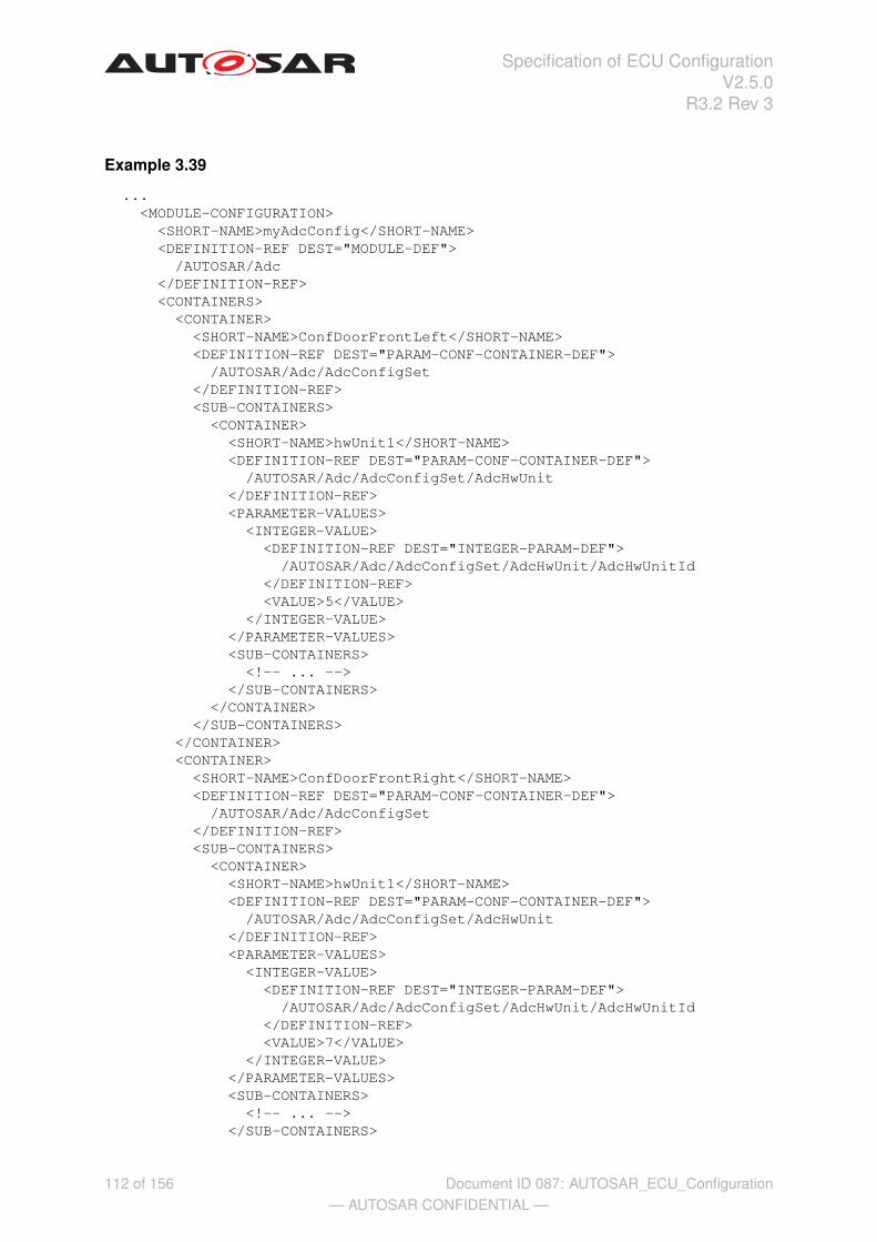
Specification of ECU ConfigurationV2.5.0
R3.2 Rev 3
Example 3.39
...<MODULE-CONFIGURATION>
<SHORT-NAME>myAdcConfig</SHORT-NAME><DEFINITION-REF DEST="MODULE-DEF">
/AUTOSAR/Adc</DEFINITION-REF><CONTAINERS>
<CONTAINER><SHORT-NAME>ConfDoorFrontLeft</SHORT-NAME><DEFINITION-REF DEST="PARAM-CONF-CONTAINER-DEF">
/AUTOSAR/Adc/AdcConfigSet</DEFINITION-REF><SUB-CONTAINERS>
<CONTAINER><SHORT-NAME>hwUnit1</SHORT-NAME><DEFINITION-REF DEST="PARAM-CONF-CONTAINER-DEF">
/AUTOSAR/Adc/AdcConfigSet/AdcHwUnit</DEFINITION-REF><PARAMETER-VALUES>
<INTEGER-VALUE><DEFINITION-REF DEST="INTEGER-PARAM-DEF">
/AUTOSAR/Adc/AdcConfigSet/AdcHwUnit/AdcHwUnitId</DEFINITION-REF><VALUE>5</VALUE>
</INTEGER-VALUE></PARAMETER-VALUES><SUB-CONTAINERS>
<!-- ... --></SUB-CONTAINERS>
</CONTAINER></SUB-CONTAINERS>
</CONTAINER><CONTAINER>
<SHORT-NAME>ConfDoorFrontRight</SHORT-NAME><DEFINITION-REF DEST="PARAM-CONF-CONTAINER-DEF">
/AUTOSAR/Adc/AdcConfigSet</DEFINITION-REF><SUB-CONTAINERS>
<CONTAINER><SHORT-NAME>hwUnit1</SHORT-NAME><DEFINITION-REF DEST="PARAM-CONF-CONTAINER-DEF">
/AUTOSAR/Adc/AdcConfigSet/AdcHwUnit</DEFINITION-REF><PARAMETER-VALUES>
<INTEGER-VALUE><DEFINITION-REF DEST="INTEGER-PARAM-DEF">
/AUTOSAR/Adc/AdcConfigSet/AdcHwUnit/AdcHwUnitId</DEFINITION-REF><VALUE>7</VALUE>
</INTEGER-VALUE></PARAMETER-VALUES><SUB-CONTAINERS>
<!-- ... --></SUB-CONTAINERS>
112 of 156— AUTOSAR CONFIDENTIAL —
Document ID 087: AUTOSAR_ECU_Configuration

Specification of ECU ConfigurationV2.5.0
R3.2 Rev 3
</CONTAINER></SUB-CONTAINERS>
</CONTAINER></CONTAINERS>
</MODULE-CONFIGURATION>...
In this example the Adc module is used to illustrate the two configuration sets. The Adcmodule is initialized by the EcuM module. So the EcuM needs to know which configu-ration set to be used for the initialization of the Adc. So in the configuration descriptionof the EcuM there needs to be a reference defined to choose the configuration set. Forthe example 3.39 the references to the two configuration set are:
<VALUE-REF>/myAdcConfig/ConfDoorFrontLeft</VALUE-REF> and
<VALUE-REF>/myAdcConfig/ConfDoorFrontRight</VALUE-REF>.
With such references any configuration set can be addressed explicitly.
113 of 156— AUTOSAR CONFIDENTIAL —
Document ID 087: AUTOSAR_ECU_Configuration

Specification of ECU ConfigurationV2.5.0
R3.2 Rev 3
4 ECU Configuration Parameter Definition SWSimplications
In this section several aspects of applying the ECU Configuration Specification toAUTOSAR specifications are described.
The ECU Configuration Parameter Definitions are distributed over the BSW SWS doc-uments. How these parameters are specified in the documents is described in sec-tion 4.1.
How the AUTOSAR COM-Stack is configured from an inter-module perspective is de-scribed in section 4.3.
4.1 Formalization aspects
The goal of this section is to describe how the ECU Configuration Parameter Defini-tions of BSW modules are specified in the SWS documents. Therefore there is notnecessarily a simple translation of the ECU Configuration Parameter’s values in theECU Configuration Description (XML file) into the module’s configuration (header file).It is the duty of the module’s generation tool to transform the configuration informationfrom the XML file into a header file.
The ECU Configuration Parameter Definitions are formalized in an UML model. ThisUML model is used to partly generate the specification tables of the BSW SWS and togenerate the ECU Configuration Parameter Definition XML file.
Some formalization patterns have been applied when developing the ECU Configura-tion Parameter Definition:
• Modified parameter names: Due to the limitations imposed by the AUTOSARXML format (32 character limit starting with a letter, etc.) the names of parametersand containers have been redefined. Also a different naming schema has beenapplied. The original names from the SWS are provided in this document as well.
• Added parameter multiplicities: In the original tables from the BSW SWS there isno possibility to specify the optionality and multiplicity of parameters. The param-eter multiplicities have been added.
• Added references: To allow a better interaction of the configuration descriptionsof several modules references between the configuration have been introduced.
• Harmonized parameter types:
– Boolean: Some parameters have been defined as enumeration or#define where the actual information stored is of type boolean. In thosecases they have been modeled as boolean.
– Float: Some parameters store a time value as integer where it is statedthat this is a time in e.g. micro-seconds. If the time specified is an absolute
114 of 156— AUTOSAR CONFIDENTIAL —
Document ID 087: AUTOSAR_ECU_Configuration

Specification of ECU ConfigurationV2.5.0
R3.2 Rev 3
time it has been formalized as a float in seconds. If the time is a factor ofsome given time-base the integer is preserved.
4.1.1 ECU Configuration Parameter Definition table
The configuration parameters are structured into containers which can hold parame-ters, references and other containers. Beside the graphical visualization in UML dia-grams, tables are used to specify the structure of the parameters.
In the following table one container is specified which holds two parameters and alsotwo additional containers as an example.
SWS Item [SWS requirement IDs]Container Name ContainerName {original name from SWS}Description Container description.Configuration Parameters
Name ParameterName {original name from SWS} [SWS requiremenets IDs]Description Parameter description.Multiplicity Parameter multiplicityType Parameter typeConfiguration Class Pre-compile time X Variant1 (Pre-compile
Configuration)Link time X Variant2 (Link-time
Configuration), Variant3(Post-build Configuration)
Post-build time –Scope / Dependency
Name EnumerationTest {ENUMERATION_TEST} [SWS0815]Description description.Multiplicity 0..1 (optional)Type EnumerationParamDefRange ReceiveUnqueuedExternal
ReceiveUnqueuedInternalSendStaticExternalSendStaticInternal
Configuration Class Pre-compile time X Variant1 (Pre-compileConfiguration)
Link time X Variant2 (Link-timeConfiguration), Variant3(Post-build Configuration)
Post-build time –Scope / DependencyIncluded ContainersContainer Name Multiplicity Scope / DepedencyContainer_1 0..1 Optional sub-container.Container_2 0..* Optional sub-container which can be present several
times.
For a detailed description of the elements in the tables please refer to chapter 3.
115 of 156— AUTOSAR CONFIDENTIAL —
Document ID 087: AUTOSAR_ECU_Configuration
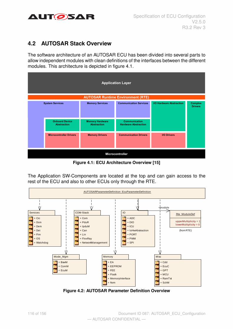
Specification of ECU ConfigurationV2.5.0
R3.2 Rev 3
4.2 AUTOSAR Stack Overview
The software architecture of an AUTOSAR ECU has been divided into several parts toallow independent modules with clean definitions of the interfaces between the differentmodules. This architecture is depicted in figure 4.1.
Figure 4.1: ECU Architecture Overview [15]
The Application SW-Components are located at the top and can gain access to therest of the ECU and also to other ECUs only through the RTE.
AUTOSARParameterDefinition :EcuParameterDefinition
Misc
+ Cdd
+ EcuC
+ GPT
+ MCU
+ RamTst
+ SchM
IO
+ ADC
+ DIO
+ ICU
+ IoHwAbstraction
+ PORT
+ PWM
+ SPI
Services
+ Crc
+ Dcm
+ Dem
+ Det
+ Fim
+ OS
+ Watchdog
Mode_Mgm
+ BswM
+ ComM
+ EcuM
Memory
+ EA
+ EEPROM
+ FEE
+ Flash
+ MemoryInterface
+ Nvm
Rte :ModuleDef
upperMultipl icity = 1lowerMultipl icity = 0
(from RTE)
COM-Stack
+ Com
+ PduR
+ IpduM
+ Can
+ Lin
+ FlexRay
+ NetworkManagement
+module
Figure 4.2: AUTOSAR Parameter Definition Overview
116 of 156— AUTOSAR CONFIDENTIAL —
Document ID 087: AUTOSAR_ECU_Configuration
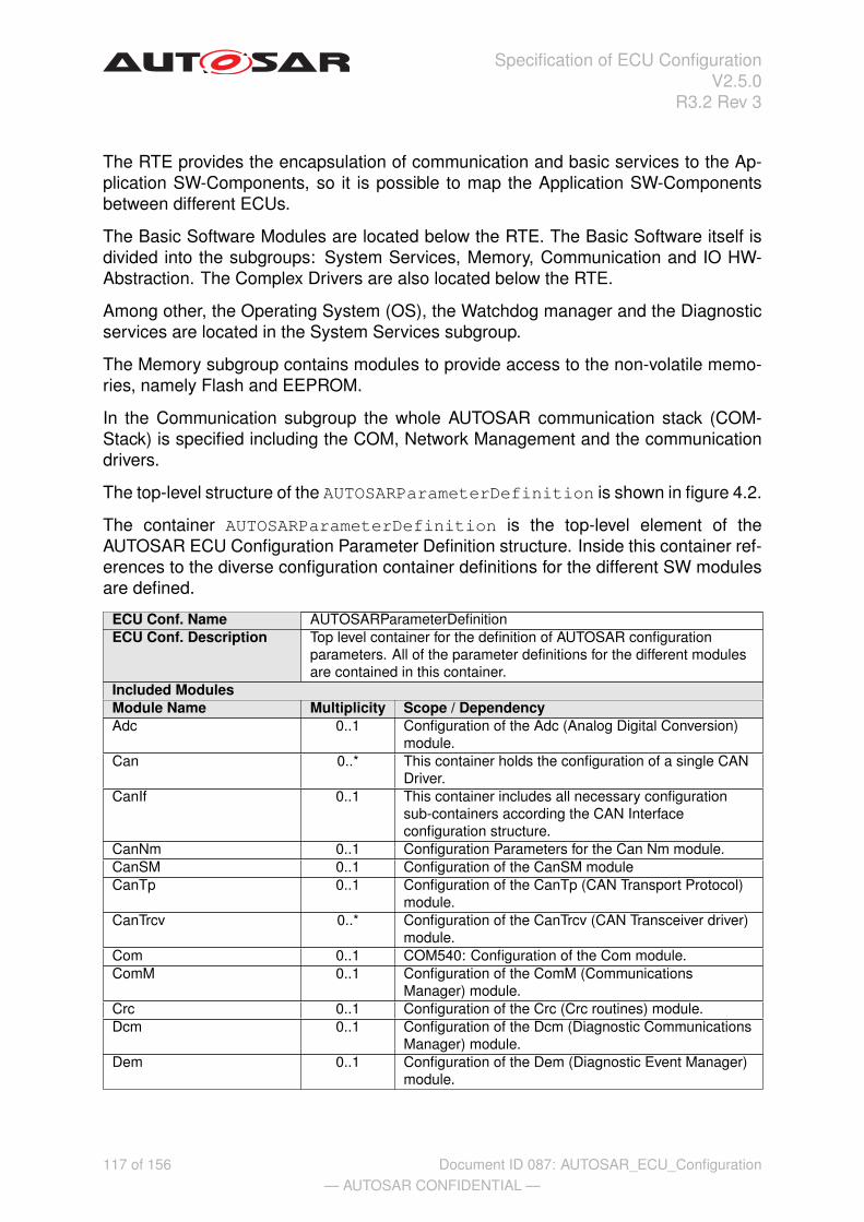
Specification of ECU ConfigurationV2.5.0
R3.2 Rev 3
The RTE provides the encapsulation of communication and basic services to the Ap-plication SW-Components, so it is possible to map the Application SW-Componentsbetween different ECUs.
The Basic Software Modules are located below the RTE. The Basic Software itself isdivided into the subgroups: System Services, Memory, Communication and IO HW-Abstraction. The Complex Drivers are also located below the RTE.
Among other, the Operating System (OS), the Watchdog manager and the Diagnosticservices are located in the System Services subgroup.
The Memory subgroup contains modules to provide access to the non-volatile memo-ries, namely Flash and EEPROM.
In the Communication subgroup the whole AUTOSAR communication stack (COM-Stack) is specified including the COM, Network Management and the communicationdrivers.
The top-level structure of the AUTOSARParameterDefinition is shown in figure 4.2.
The container AUTOSARParameterDefinition is the top-level element of theAUTOSAR ECU Configuration Parameter Definition structure. Inside this container ref-erences to the diverse configuration container definitions for the different SW modulesare defined.
ECU Conf. Name AUTOSARParameterDefinitionECU Conf. Description Top level container for the definition of AUTOSAR configuration
parameters. All of the parameter definitions for the different modulesare contained in this container.
Included ModulesModule Name Multiplicity Scope / DependencyAdc 0..1 Configuration of the Adc (Analog Digital Conversion)
module.Can 0..* This container holds the configuration of a single CAN
Driver.CanIf 0..1 This container includes all necessary configuration
sub-containers according the CAN Interfaceconfiguration structure.
CanNm 0..1 Configuration Parameters for the Can Nm module.CanSM 0..1 Configuration of the CanSM moduleCanTp 0..1 Configuration of the CanTp (CAN Transport Protocol)
module.CanTrcv 0..* Configuration of the CanTrcv (CAN Transceiver driver)
module.Com 0..1 COM540: Configuration of the Com module.ComM 0..1 Configuration of the ComM (Communications
Manager) module.Crc 0..1 Configuration of the Crc (Crc routines) module.Dcm 0..1 Configuration of the Dcm (Diagnostic Communications
Manager) module.Dem 0..1 Configuration of the Dem (Diagnostic Event Manager)
module.
117 of 156— AUTOSAR CONFIDENTIAL —
Document ID 087: AUTOSAR_ECU_Configuration

Specification of ECU ConfigurationV2.5.0
R3.2 Rev 3
Module Name Multiplicity Scope / DependencyDet 0..1 Configuration of the Det (Development Error Tracer)
module.There are NO standardized configuration parametersdefined. All the configuration of the Det is done viavendor-specific configuration parameters which needto be defined inside this ModuleDef.
Dio 0..1 Configuration of the Dio (Digital IO) module.Ea 0..* Configuration of the Ea (EEPROM Abstraction)
module.The module shall abstract from the device specificaddressing scheme and segmentation and provide theupper layers with a virtual addressing scheme andsegmentation as well as a "virtually" unlimited numberof erase cycles.
EcuC 0..1 Virtual module to collect ECU Configuration specific /global configuration information.
EcuM 0..1 Configuration of the EcuM (ECU State Manager)module.
Eep 0..* Configuration of the Eep (internal or externalEEPROM driver) module.Its multiplicity describes the number of EEPROMdrivers present, so there will be one container for eachEEPROM driver in the ECUC template. When noEEPROM driver is present then the multiplicity is 0.
Fee 0..* Configuration of the Fee (Flash EEPROM Emulation)module.
Fim 0..1 Configuration of the Fim (Function Inhibition Manager)module.
Fls 0..* Configuration of the Fls (internal or external flashdriver) module.Its multiplicity describes the number of flash driverspresent, so there will be one container for each flashdriver in the ECUC template. When no flash driver ispresent then the multiplicity is 0.
Fr 0..* Configuration of the Fr (FlexRay driver) module.FrIf 0..1 Configuration of the FrIf (FlexRay Interface) module.FrNm 0..1 The Flexray Nm moduleFrSm 0..1FrTp 0..1 Configuration of the FrTp (FlexRay Transport Protocol)
module.FrTrcv 0..* Configuration of the FrTrcv (FlexRay Transceiver
driver) module.Gpt 0..1 Configuration of the Gpt (General Purpose Timer)
module.IPduMplex 0..1 Configuration of the IPduMplex (IPdu Multiplexer)
module.Icu 0..* Configuration of the Icu (Input Capture Unit) module.IoHwAbstraction 0..1 Configuration of IO HW Abstraction.Lin 0..* Configuration of the Lin (LIN driver) module.LinIf 0..1 Configuration of the LinIf (LIN Interface) module.LinSM 0..1 Configuration of the Lin State Manager module.LinTp 0..1 Singleton descriptor for the LIN Transport Protocol.Mcu 0..1 Configuration of the Mcu (Microcontroler Unit) module.
118 of 156— AUTOSAR CONFIDENTIAL —
Document ID 087: AUTOSAR_ECU_Configuration
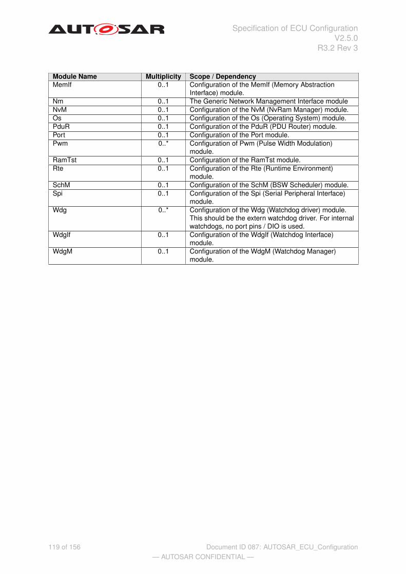
Specification of ECU ConfigurationV2.5.0
R3.2 Rev 3
Module Name Multiplicity Scope / DependencyMemIf 0..1 Configuration of the MemIf (Memory Abstraction
Interface) module.Nm 0..1 The Generic Network Management Interface moduleNvM 0..1 Configuration of the NvM (NvRam Manager) module.Os 0..1 Configuration of the Os (Operating System) module.PduR 0..1 Configuration of the PduR (PDU Router) module.Port 0..1 Configuration of the Port module.Pwm 0..* Configuration of Pwm (Pulse Width Modulation)
module.RamTst 0..1 Configuration of the RamTst module.Rte 0..1 Configuration of the Rte (Runtime Environment)
module.SchM 0..1 Configuration of the SchM (BSW Scheduler) module.Spi 0..1 Configuration of the Spi (Serial Peripheral Interface)
module.Wdg 0..* Configuration of the Wdg (Watchdog driver) module.
This should be the extern watchdog driver. For internalwatchdogs, no port pins / DIO is used.
WdgIf 0..1 Configuration of the WdgIf (Watchdog Interface)module.
WdgM 0..1 Configuration of the WdgM (Watchdog Manager)module.
119 of 156— AUTOSAR CONFIDENTIAL —
Document ID 087: AUTOSAR_ECU_Configuration
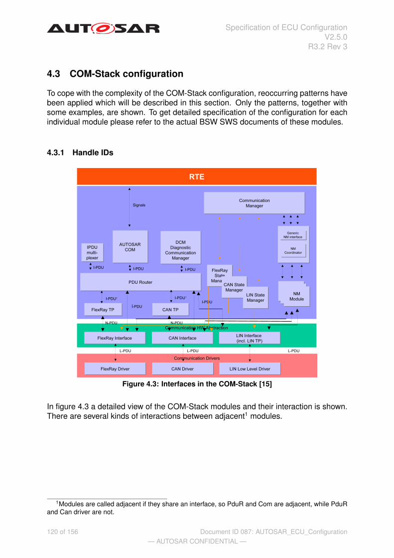
Specification of ECU ConfigurationV2.5.0
R3.2 Rev 3
4.3 COM-Stack configuration
To cope with the complexity of the COM-Stack configuration, reoccurring patterns havebeen applied which will be described in this section. Only the patterns, together withsome examples, are shown. To get detailed specification of the configuration for eachindividual module please refer to the actual BSW SWS documents of these modules.
4.3.1 Handle IDs
Figure 4.3: Interfaces in the COM-Stack [15]
In figure 4.3 a detailed view of the COM-Stack modules and their interaction is shown.There are several kinds of interactions between adjacent1 modules.
1Modules are called adjacent if they share an interface, so PduR and Com are adjacent, while PduRand Can driver are not.
120 of 156— AUTOSAR CONFIDENTIAL —
Document ID 087: AUTOSAR_ECU_Configuration

Specification of ECU ConfigurationV2.5.0
R3.2 Rev 3
4.3.1.1 Handle ID concept
The API definitions in the COM-Stack utilize two concepts to achieve the interactionbetween adjacent modules:
• Pointers to PDU data buffer (the PDU data buffer contains the actual communi-cated information, depending on the actual layer the interaction happens)
• Handle IDs to identify to what PDU the pointer is referring to.
A typical API call is for instance:
PduR_ComTransmit(PduIdType ComTxPduId, PduInfoType *PduInfoPtr)
Handle IDs are defined by the module providing the API and used by the module callingthe API in case of direct transmission and reception. In case of TriggerTransmit andTxConfirmation the Handle ID defined by the lower layer module is used.
The choice of the value for a Handle ID is open to the implementation of the providingmodule. There might be different strategies to optimize the Handle ID values andtherefore the internal structures of the implementation may have an influence on thechoice of the values.
Also the Handle IDs can be chosen freely per module, so a PDU might be sent fromCom to the PduR with the ID=5 and then the PduR transmits it further to the CanIf withID=19. In the configuration information of the PduR it has to be possible to concludethat if a PDU arrives from Com with ID=5 it has to be forwarded to the CanIf withID=19.
It has to be guaranteed that each Pdu does have a unique handle ID within the scopeof the corresponding API. For example: The PduR gets transmission requests fromboth, the Com and the Dcm modules. But there are also two distinct APIs defined forthose requests:
• PduR_ComTransmit(...)
• PduR_DcmTransmit(...)
Therefore the PduR can distinguish two PDUs, even when they have the same handleID but are requested via different APIs.
Another use-case in the COM-Stack only provides one API for all the callers: the inter-face layer (CanIf, FrIf, LinIf).
• CanIf_Transmit(...)
Here it has to be guaranteed that each transmit request for a distinct PDU does havea unique handle ID.
The actual values of the handle IDs can only be allocated properly when the configu-ration of one module is completed, since only then the internal data structures can bedefined.
121 of 156— AUTOSAR CONFIDENTIAL —
Document ID 087: AUTOSAR_ECU_Configuration

Specification of ECU ConfigurationV2.5.0
R3.2 Rev 3
In the next sections the patterns used to define and utilize Handle IDs are described.
122 of 156— AUTOSAR CONFIDENTIAL —
Document ID 087: AUTOSAR_ECU_Configuration

Specification of ECU ConfigurationV2.5.0
R3.2 Rev 3
4.3.1.2 Definition of Handle IDs
The ECU Configuration Description (which holds the actual values of configurationparameters) is structured according to the individual BSW Module instances. Thereforethe ECU Configuration Parameter Definition is also structured in this way.
In figure 4.4 an exemplary definition of a partial Can Interface transmit configuration isshown.
CanIfTxPduConfig :ParamConfContainerDef
upperMultipl icity = *lowerMultipl icity = 0
CanIfCanTxPduId :IntegerParamDef
symbolicNameValue = trueupperMultipl icity = 1lowerMultipl icity = 1
CanIfInitConfiguration :ParamConfContainerDef
upperMultiplicity = *lowerMultiplicity = 1multipleConfigurationContainer = true
CanIfCanTxPduIdCanId :IntegerParamDef
CanIfCanTxPduIdDlc :IntegerParamDef
min = 0max = 8
+subContainer
+parameter
+parameter
+parameter
Figure 4.4: Example of Can Interface Tx configuration
The configuration of the module CanIf may contain several CanIfTxPduConfig ob-jects.
Each CanIfTxPduConfig object contains information on one Pdu which is comingfrom an upper layer (e.g. PduR or Nm) and is going to some Can driver. In thisexample the CanIfCanTxPduCanId and CanIfCanTxPduDlc are specified for eachto be transmitted Pdu. There is a similar structure needed for the receive use-case aswell.
Additionally the parameter CanIfCanTxPduId is specified. This integer parameterwill later hold the actual value for the handle ID. So the handle ID value is stored insidethe structure of the defining module.
Since the handle ID CanIfCanTxPduId is part of the container CanIfTxPduConfigthe semantics of the symbolic names can be applied.
[ecuc_sws_2106] If a configuration parameter holds a handle Id which needs to beshared between several modules it shall have the symbolicNameValue = true set.
123 of 156— AUTOSAR CONFIDENTIAL —
Document ID 087: AUTOSAR_ECU_Configuration

Specification of ECU ConfigurationV2.5.0
R3.2 Rev 3
Thus it is required that all handle Id values are accessible via a symbolic name refer-ence (see section 4.3.1.5).
4.3.1.3 Definition of PDUs
With the possibility to define Handle IDs a module is now able to publish the Handle IDvalues to other modules. In this section it shall be described how other modules canrelate to those Handle IDs and how to define the flow of a PDU2 through the COM-Stack.
To be able to define a PDU "flowing" through the COM-Stack two modules need to beable to refer to the same PDU object. Therefore a generic Pdu container has beendefined which does not belong to any module but to the whole COM-Stack.
Since the PDU flowing through the COM-Stack does not belong to an individual mod-ule, the "virtual" module EcuC has been introduced in the ECU Configuration. Thismodule is used to collect configuration information not associated with any specificstandardized module.
The PduCollection may contain several "global" Pdu objects as shown in figure 4.5.Each Pdu may be representing an actual PduToFrameMapping3 from the AUTOSARSystem Description[10] (the ECU Extract), therefore there is an optional reference toan element in the System Template. The reference is optional because the PDUs whichare transported within an ECU only are not necessarily part of the ECU Extract. Es-pecially PDUs handled by the Transport Protocol modules have no representation inthe ECU Extract (There is a PDU coming over the bus which is represented by a Pduobject, but when the TP does the conversion and a new Pdu is created which then isforwarded to the upper layer. This created Pdu does not have a reference to a PduT-oFrameMapping).
2For this aspect of the configuration it does not matter what kind of PDU it is, i.e. I-PDU, L-PDU orN-PDU.
3The element PduToFrameMapping represents the actual PDU in the specific ECU (formerly knownas PduInstance)
124 of 156— AUTOSAR CONFIDENTIAL —
Document ID 087: AUTOSAR_ECU_Configuration

Specification of ECU ConfigurationV2.5.0
R3.2 Rev 3
System Template
PduCollection :ParamConfContainerDef
upperMultiplicity = 1lowerMultiplicity = 0
Pdu :ParamConfContainerDef
upperMultiplicity = *lowerMultiplicity = 0
EcuC :ModuleDef
upperMultipl icity = 1lowerMultipl icity = 0
Identifiable
CoreCommunication::PduToFrameMapping
+ packingByteOrder :ByteOrderEnum+ startPosition :Integer+ updateIndicationBitPosition :Integer [0..1]
SysTPduToFrameMappingRef :ForeignReferenceParamDef
upperMultipl icity = 1lowerMultipl icity = 0destinationType = PduToFrameMapping
PduLength :IntegerParamDef
+reference
+parameter
+container
+subContainer
Figure 4.5: Generic Pdu Container
Pdu
SWS ItemContainer Name PduDescription One Pdu flowing through the COM-Stack.
This Pdu is used by all Com-Stack modules to aggree on referencingthe same Pdu.
Configuration Parameters
Name PduLengthDescription Length in bits of the Pdu.Multiplicity 1Type IntegerParamDefDefault ValueConfiguration Class Pre-compile time –
Link time –Post-build time –
Scope / Dependency
Name SystemTemplatePduToFrameMappingRefDescription Optional reference to the PduToFrameMapping from the
SystemTemplate which this Pdu represents.Multiplicity 0..1Type Foreign reference to PduToFrameMappingConfiguration Class Pre-compile time –
Link time –Post-build time –
Scope / DependencyNo Included Containers
125 of 156— AUTOSAR CONFIDENTIAL —
Document ID 087: AUTOSAR_ECU_Configuration
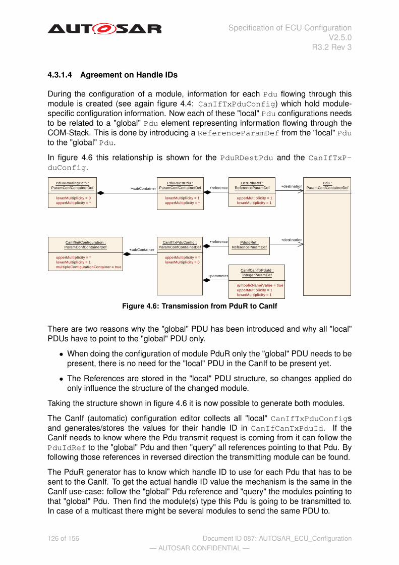
Specification of ECU ConfigurationV2.5.0
R3.2 Rev 3
4.3.1.4 Agreement on Handle IDs
During the configuration of a module, information for each Pdu flowing through thismodule is created (see again figure 4.4: CanIfTxPduConfig) which hold module-specific configuration information. Now each of these "local" Pdu configurations needsto be related to a "global" Pdu element representing information flowing through theCOM-Stack. This is done by introducing a ReferenceParamDef from the "local" Pduto the "global" Pdu.
In figure 4.6 this relationship is shown for the PduRDestPdu and the CanIfTxP-duConfig.
PduRRoutingPath :ParamConfContainerDef
lowerMultiplicity = 0upperMultiplicity = *
PduRDestPdu :ParamConfContainerDef
lowerMultipl icity = 1upperMultipl icity = *
Pdu :ParamConfContainerDef
DestPduRef :ReferenceParamDef
upperMultipl icity = 1lowerMultiplicity = 1
CanIfTxPduConfig :ParamConfContainerDef
upperMultipl icity = *lowerMultipl icity = 0
CanIfCanTxPduId :IntegerParamDef
symbolicNameValue = trueupperMultipl icity = 1lowerMultiplicity = 1
CanIfInitConfiguration :ParamConfContainerDef
upperMultiplicity = *lowerMultiplicity = 1multipleConfigurationContainer = true
PduIdRef :ReferenceParamDef
+destination
+destination
+parameter
+reference
+reference+subContainer
+subContainer
Figure 4.6: Transmission from PduR to CanIf
There are two reasons why the "global" PDU has been introduced and why all "local"PDUs have to point to the "global" PDU only.
• When doing the configuration of module PduR only the "global" PDU needs to bepresent, there is no need for the "local" PDU in the CanIf to be present yet.
• The References are stored in the "local" PDU structure, so changes applied doonly influence the structure of the changed module.
Taking the structure shown in figure 4.6 it is now possible to generate both modules.
The CanIf (automatic) configuration editor collects all "local" CanIfTxPduConfigsand generates/stores the values for their handle ID in CanIfCanTxPduId. If theCanIf needs to know where the Pdu transmit request is coming from it can follow thePduIdRef to the "global" Pdu and then "query" all references pointing to that Pdu. Byfollowing those references in reversed direction the transmitting module can be found.
The PduR generator has to know which handle ID to use for each Pdu that has to besent to the CanIf. To get the actual handle ID value the mechanism is the same in theCanIf use-case: follow the "global" Pdu reference and "query" the modules pointing tothat "global" Pdu. Then find the module(s) type this Pdu is going to be transmitted to.In case of a multicast there might be several modules to send the same PDU to.
126 of 156— AUTOSAR CONFIDENTIAL —
Document ID 087: AUTOSAR_ECU_Configuration

Specification of ECU ConfigurationV2.5.0
R3.2 Rev 3
With this approach a high degree of decoupling has been achieved between the con-figuration information of the involved modules. Even when modules are adjacent andneed to share information like handle ID, the references between the modules are al-ways indirect using the "global" Pdu elements.
4.3.1.5 Handle IDs with symbolic names
The usage of handle Ids together with symbolic names is targeting several use-casesfor the methodology of configuring adjacent modules. For the definition of possibleconfiguration approaches please refer to section A.1.1.
For the discussion of the Handle Id use-cases two basic approaches can be distin-guished when dividing the methodology into the steps configuration editing and modulegeneration:
• Handle Ids allocated by the configuration editor
• Handle Ids allocated by the module generator
It is assumed that the configuration and generation of the whole stack is done usingdifferent tools (possibly from different vendors) which might have either of the two ap-proaches implemented.
In requirement [ecuc_sws_2106] it is required that all handle Ids are represented assymbolicNameValue = true configuration parameters thus decoupling the valuefrom its usage.
In requirement [ecuc_sws_2107] it is required that the allocated values are stored inthe XML (latest after module generation) so the allocated values are documented. Incase the allocation of values has to be performed at a later point in time again (withupdated input information) the non affected values can be preserved. It is also neededto support debugging.
In requirement [ecuc_sws_2108] it is required that the handle Id values are alwaysgenerated into the module’s header file. With this approach it is possible to freelychoose the configuration approach of the adjacent modules.
This approach has significant effect on the methodology due to the circular depen-dencies between the adjacent modules( Com sends to the PduR using PduR handleIds, PduR indicates to Com using Com handle Ids). Therefore the configuration of alladjacent modules has to be re-visited in case some handle Id changes happen. Thiscontributes to the approach that FIRST the configuration of the stack is performed andSECOND the generation is triggered.
An example of this approach is provided below: By adding the attribute symbol-icNameValue=true to the parameter holding the handle ID (in figure 4.6 this isthe parameter CanIfTxPduId) the code generator doing the CanIf will generate a#define in the CanIf_cfg.h file. The name of the define is the name of the parent
127 of 156— AUTOSAR CONFIDENTIAL —
Document ID 087: AUTOSAR_ECU_Configuration

Specification of ECU ConfigurationV2.5.0
R3.2 Rev 3
container (each container does have a short name) and the value is the actual numberassigned to that handle ID.
For example in CanIf_cfg.h:
#define CanIfTx_Pdu_2345634_985_symbol 17
The benefit is that the generator of the PduR does not need to wait for the CanIf tobe configured completely and handle IDs are generated. If the CanIf publishes thesymbolic names for the handle IDs, the PduR can expect those symbolic names andgenerate the PduR code using those symbolic names.
For example in PduR.c:
CanIf_Transmit( CanIfTx_Pdu_2345634_985_symbol, PduPtr )
Therefore the PduR can be generated as soon as its own configuration is finished andthere is no need to wait for the CanIf to be finished completely. However, at least the"local" Pdu in the CanIf has to be already created to allow this, because the name ofthe symbol has to be fetched from this configuration.
Of course the PduR can only be compiled after the CanIf has been generated as well,but with the utilization of the symbolic names together with handle IDs an even higherdegree of decoupling in the configuration process is achieved.
4.3.2 Configuration examples for the Pdu Router
In this section several use-cases of the PduR are described from the configuration pointof view. The focus is on the interaction of the PduR configuration with the configurationof the other COM-Stack modules. Therefore only some configuration parameters areactually shown in these examples.
4.3.2.1 Tx from Com to CanIf
In the example in figure 4.7 a Pdu is sent from the Com module – via the Pdu Router –to the Can Interface. Since this one Pdu is handed over through these layers there isonly need for one global Pdu object System_Pdu.
The Com module’s configuration points to the System_Pdu to indicate which Pdu shallbe sent. The actual Handle Id which has to be used in the API call will however bedefined by the PduR in the parameter PduRSrcPdu::HandleId. In this example theCom module has to use the Hanlde Id 23 to transmit this Pdu to the PduR.
Then, since the CanIf is pointing to the same System_Pdu the PduR can be configuredto send this Pdu to the CanIf. The Handle Id is defined in the CanIf configuration in theparameter value of CanIfCanTxPduId.
128 of 156— AUTOSAR CONFIDENTIAL —
Document ID 087: AUTOSAR_ECU_Configuration

Specification of ECU ConfigurationV2.5.0
R3.2 Rev 3
ComIPdu :Container PduIdRef :ReferenceValue
System_Pdu :Container
PduRRoutingPath :Container
PduRSrcPdu :Container
PduRDestPdu :Container
SrcPduRef :ReferenceValue
HandleId :IntegerValue
value = 23
DestPduRef :ReferenceValue
CanIfTxPduConfig :Container
CanIfCanTxPduId :IntegerValue
value = 6
PduIdRef :ReferenceValue
Figure 4.7: Tx from Com to CanIf example
129 of 156— AUTOSAR CONFIDENTIAL —
Document ID 087: AUTOSAR_ECU_Configuration

Specification of ECU ConfigurationV2.5.0
R3.2 Rev 3
4.3.2.2 Rx from CanIf to Com
In the example in figure 4.8 the reception use-case from the CanIf to the Com moduleis configured. Here the Handle Ids are defined in the PduR and the Com module’sconfiguration.
ComIPdu :Container PduIdRef :ReferenceValue
System_Pdu :Container
PduRRoutingPath :Container
PduRSrcPdu :Container
PduRDestPdu :Container
SrcPduRef :ReferenceValue
HandleId :IntegerValue
value = 17
DestPduRef :ReferenceValue
CanIfCanRxPduId :Container
ComRxIPduHandleId :IntegerValue
value = 3
PduIdRef :ReferenceValue
Figure 4.8: Rx from CanIf to Com example
130 of 156— AUTOSAR CONFIDENTIAL —
Document ID 087: AUTOSAR_ECU_Configuration

Specification of ECU ConfigurationV2.5.0
R3.2 Rev 3
4.3.2.3 Gateway from CanIf to FrIf
In the example in figure 4.9 the gateway use-case is shown. Since there are twoPdus involved there are two System_Pdu objects defined: one which is representingthe Can Pdu and one which represents the Fr Pdu. Via the references to these twoSystem_Pdu objects the gateway is configured.
System_Can_Pdu :Container
CanIfCanRxPduId :Container
PduIdRef :ReferenceValue
PduRRoutingPath :Container
PduRSrcPdu :Container
PduRDestPdu :Container
SrcPduRef :ReferenceValue
HandleId :IntegerValue
value = 17
DestPduRef :ReferenceValue
System_Fr_Pdu :Container
FrIfTxPdu :Container PduIdRef :ReferenceValue
HandleId :IntegerValue
value = 2
Figure 4.9: Gateway from CanIf to FrIf example
4.4 CDD module
The CDD module describes the minimal requirements that are necessary for the con-figuration of a Complex Device Driver with respect to the surrounding standardizedBSW modules.
[ecuc_sws_6031] If a complex device driver wants to interact with a surrounding stan-dardized BSW module it has to define a Vendor Specific Module Definition from theStandardized CDD Module Definition. The rules that must be followed when generat-ing the Vendor Specific Module Definition are described in chapter 5.1.
131 of 156— AUTOSAR CONFIDENTIAL —
Document ID 087: AUTOSAR_ECU_Configuration

Specification of ECU ConfigurationV2.5.0
R3.2 Rev 3
As defined in [ecuc_sws_6001] the shortName of a VSMD module shall be the sameas the shortName of the StMD. According to this requirement the shortName of themodule definition of a complex device driver is always "Cdd".
[ecuc_sws_6036] To distinguish module definitions of complex device drivers fromeach other the package structure shall be used.
[ecuc_sws_6037] The apiServicePrefix attribute of a complex device driver shallcontain the module abbreviation..
[constr_3023] Usage of apiServicePrefix dThe attribute apiServicePrefix ismandatory for VSMDs derived from the CDD StMD. The attribute shall not be providedfor VSMDs derived from any other StMDs. c
Consider a complex device driver named "MyCdd". The VSMD of this complex devicedriver has to be derived from the CDD StMD. The shortName of the module definitionof this complex device driver has to be equal to "CDD". The apiServicePrefixattribute is mandatory for the VSMD of this complex device driver and has to be equalto "MyCdd".
Note that the configuration parameters for the VSMD of CDD do not specify any config-uration class. It is up to the implementor of the specific CDD to define the configurationclass for all configuration parameters - standardized and vendor specific ones.
If a CDD implementation does not utilize the post build configuration the Cdd moduledefinition shall directly aggregate the CddComStackContribution container.
If a CDD implementation does utilize the post build configuration the Cdd module def-inition shall aggregate the CddConfigSet, which in turn aggregates the CddCom-StackContribution container.
Module Name CddModule Description The CDD module describes the minimal requirements that are
necessary for the configuration of a CDD with respect to thesurrounding standardized BSW modules.
Included ContainersContainer Name Multiplicity Scope / DependencyCddComStackContribution 0..1 Contribution of COM Stack modules.CddConfigSet 0..1 Configuration set container of the Cdd.
Cdd :ModuleDef
lowerMultiplicity = 0upperMultipl icity = *
CddComStackContribution :ParamConfContainerDef
lowerMultiplicity = 0upperMultiplicity = 1
CddConfigSet :ParamConfContainerDef
lowerMultiplicity = 0upperMultipl icity = 1multipleConfigurationContainer = true
+container
+container
+subContainer
Figure 4.10: Cdd Module
132 of 156— AUTOSAR CONFIDENTIAL —
Document ID 087: AUTOSAR_ECU_Configuration

Specification of ECU ConfigurationV2.5.0
R3.2 Rev 3
CddConfigSet
SWS Item [EcuC067_Conf]Container Name CddConfigSet[Multi Config Container]Description Configuration set container of the Cdd.Configuration ParametersIncluded ContainersContainer Name Multiplicity Scope / DepedencyCddComStackContribution
0..1 Contribution of COM Stack modules.
CddComStackContribution
SWS Item [EcuC017_Conf]Container Name CddComStackContributionDescription Contribution of COM Stack modules.Configuration ParametersIncluded ContainersContainer Name Multiplicity Scope / DepedencyCddComIfUpperLayerContribution
0..1 Parameters that are necessary for the configuration of aComplex Device Driver that serves as the UpperLayer ofthe Com Interface module.
CddPduRUpperLayerContribution
0..1 Contribution of COM Stack modules.
The following sections describe particular COM stack modules and the interaction withComplex Device Drivers.
4.4.1 Pdu Router
In the AUTOSAR COM Stack upper and lower layer Complex Device Drivers are al-lowed to access the Pdu Router. In both cases the Pdus that are exchanged betweenthe CDD and the Pdu Router shall be configured. The contribution of the ComplexDevice Driver implies a reference to the global Pdu and the definition of a HandleId.Figure 4.11 shows an example of a Complex Device Driver between the CanIf and thePduR and one Complex Device Driver above the PduR.
133 of 156— AUTOSAR CONFIDENTIAL —
Document ID 087: AUTOSAR_ECU_Configuration

Specification of ECU ConfigurationV2.5.0
R3.2 Rev 3
Figure 4.11: CDD Example
Figure 4.12 shows the CDD contribution in the configuration model.
Note that the optional presence of the TxPdu and RxPdu does not influence the exis-tence of the respective APIs in the Cdd.
134 of 156— AUTOSAR CONFIDENTIAL —
Document ID 087: AUTOSAR_ECU_Configuration

Specification of ECU ConfigurationV2.5.0
R3.2 Rev 3
CddComStackContribution :ParamConfContainerDef
lowerMultiplicity = 0upperMultiplicity = 1
CddPduRUpperLayerContribution :ParamConfContainerDef
lowerMultiplicity = 0upperMultiplicity = 1
CddPduRUpperLayerTxPdu :ParamConfContainerDef
lowerMultiplicity = 0upperMultiplicity = *
Pdu :ParamConfContainerDef
upperMultiplicity = *lowerMultiplicity = 0
CddPduRUpperLayerPduRef :ReferenceParamDef
CddPduRUpperLayerHandleId :IntegerParamDef
symbolicNameValue = truelowerMultiplicity = 0upperMultiplicity = 1min = 0max = 65535
CddComIfUpperLayerContribution :ParamConfContainerDef
lowerMultiplicity = 0upperMultipl icity = 1
CddComIfUpperLayerTxPdu :ParamConfContainerDef
lowerMultiplicity = 0upperMultiplicity = *
CddComIfPduRef :ReferenceParamDef
CddComIfHandleId :IntegerParamDef
symbolicNameValue = truelowerMultiplicity = 0upperMultiplicity = 1min = 0max = 65535
CddPduRUpperLayerRxPdu :ParamConfContainerDef
lowerMultipl icity = 0upperMultipl icity = *
CddPduRUpperLayerHandleId :IntegerParamDef
symbolicNameValue = truelowerMultiplicity = 0upperMultiplicity = 1min = 0max = 65535
CddPduRUpperLayerPduRef :ReferenceParamDef
CddComIfUpperLayerRxPdu :ParamConfContainerDef
lowerMultiplicity = 0upperMultiplicity = *
CddComIfPduRef :ReferenceParamDef
CddComIfHandleId :IntegerParamDef
symbolicNameValue = truelowerMultipl icity = 0upperMultipl icity = 1min = 0max = 65535
+destination
+subContainer
+subContainer
+subContainer
+parameter
+reference
+destination
+subContainer
+destination
+reference
+subContainer
+subContainer
+parameter
+reference
+parameter
+reference
+parameter
+destination
Figure 4.12: PduR and Com Interface contribution
CddPduRUpperLayerContribution
SWS Item [EcuC026_Conf]Container Name CddPduRUpperLayerContributionDescription Contribution of COM Stack modules.Configuration Parameters
135 of 156— AUTOSAR CONFIDENTIAL —
Document ID 087: AUTOSAR_ECU_Configuration

Specification of ECU ConfigurationV2.5.0
R3.2 Rev 3
Included ContainersContainer Name Multiplicity Scope / DepedencyCddPduRUpperLayerRxPdu
0..* This container specifies PDUs that are exchangedbetween the CDD and the standardized BSW module.
CddPduRUpperLayerTxPdu
0..* This container specifies PDUs that are exchangedbetween the CDD and the standardized BSW module.
CddPduRUpperLayerTxPdu
SWS Item [EcuC027_Conf]Container Name CddPduRUpperLayerTxPduDescription This container specifies PDUs that are exchanged between the CDD
and the standardized BSW module.Configuration Parameters
Name CddPduRUpperLayerHandleId [EcuC029_Conf]Description ECU wide unique, symbolic handle for the Pdu.Multiplicity 0..1Type IntegerParamDef (Symbolic Name generated for this parameter)Range 0 .. 65535Configuration Class Pre-compile time –
Link time –Post-build time –
Scope / Dependency
Name CddPduRUpperLayerPduRef [EcuC028_Conf]Description Reference to the "global" Pdu structure to allow harmonization of
handle IDs in the COM-Stack.Multiplicity 1Type Reference to PduConfiguration Class Pre-compile time –
Link time –Post-build time –
Scope / DependencyNo Included Containers
CddPduRUpperLayerRxPdu
SWS Item [ECUC_Cdd_00043]Container Name CddPduRUpperLayerRxPduDescription This container specifies PDUs that are exchanged between the CDD
and the standardized BSW module.Configuration Parameters
136 of 156— AUTOSAR CONFIDENTIAL —
Document ID 087: AUTOSAR_ECU_Configuration

Specification of ECU ConfigurationV2.5.0
R3.2 Rev 3
Name CddPduRUpperLayerHandleId [EcuC029_Conf]Description ECU wide unique, symbolic handle for the Pdu.Multiplicity 0..1Type IntegerParamDef (Symbolic Name generated for this parameter)Range 0 .. 65535Configuration Class Pre-compile time –
Link time –Post-build time –
Scope / Dependency
Name CddPduRUpperLayerPduRef [EcuC028_Conf]Description Reference to the "global" Pdu structure to allow harmonization of
handle IDs in the COM-Stack.Multiplicity 1Type Reference to PduConfiguration Class Pre-compile time –
Link time –Post-build time –
Scope / DependencyNo Included Containers
4.4.2 COM Interface modules
A Complex Device Driver is not allowed to access the COM Stack modules FrDrv,CanDrv and LinDrv. For these modules there is no more than one user. Therefore thelower layer of the COM Stack Bus Interface modules (FrIf, LinIf, CanIf) is not regardedin the CDD module. Upper layer Complex Device Drivers are allowed to access theinterface of these modules. Equal to the PduRContribution the CddComIfUpper-LayerContribution of the Complex Device Driver implies a reference to the globalPdu and the definition of a HandleId. Figure 4.12 shows the CDD contribution in theconfiguration model.
Note that the optional presence of the TxPdu and RxPdu does not influence the exis-tence of the respective APIs in the Cdd.
CddComIfUpperLayerContribution
SWS Item [EcuC018_Conf]Container Name CddComIfUpperLayerContributionDescription Parameters that are necessary for the configuration of a Complex
Device Driver that serves as the UpperLayer of the Com Interfacemodule.
Configuration ParametersIncluded ContainersContainer Name Multiplicity Scope / DepedencyCddComIfUpperLayerRxPdu
0..* This container specifies Tx PDUs that are exchangedbetween the CDD and the standardized BSW module.
CddComIfUpperLayerTxPdu
0..* This container specifies Tx PDUs that are exchangedbetween the CDD and the standardized BSW module.
137 of 156— AUTOSAR CONFIDENTIAL —
Document ID 087: AUTOSAR_ECU_Configuration

Specification of ECU ConfigurationV2.5.0
R3.2 Rev 3
CddComIfUpperLayerTxPdu
SWS Item [EcuC019_Conf]Container Name CddComIfUpperLayerTxPduDescription This container specifies Tx PDUs that are exchanged between the
CDD and the standardized BSW module.Configuration Parameters
Name CddComIfHandleId [EcuC021_Conf]Description ECU wide unique, symbolic handle for the Pdu.Multiplicity 0..1Type IntegerParamDef (Symbolic Name generated for this parameter)Range 0 .. 65535Configuration Class Pre-compile time –
Link time –Post-build time –
Scope / Dependency
Name CddComIfPduRef [EcuC020_Conf]Description Reference to the "global" Pdu structure to allow harmonization of
handle IDs in the COM-Stack.Multiplicity 1Type Reference to PduConfiguration Class Pre-compile time –
Link time –Post-build time –
Scope / DependencyNo Included Containers
CddComIfUpperLayerRxPdu
SWS Item [ECUC_Cdd_00049]Container Name CddComIfUpperLayerRxPduDescription This container specifies Tx PDUs that are exchanged between the
CDD and the standardized BSW module.Configuration Parameters
Name CddComIfHandleId [EcuC021_Conf]Description ECU wide unique, symbolic handle for the Pdu.Multiplicity 0..1Type IntegerParamDef (Symbolic Name generated for this parameter)Range 0 .. 65535Configuration Class Pre-compile time –
Link time –Post-build time –
Scope / Dependency
138 of 156— AUTOSAR CONFIDENTIAL —
Document ID 087: AUTOSAR_ECU_Configuration

Specification of ECU ConfigurationV2.5.0
R3.2 Rev 3
Name CddComIfPduRef [EcuC020_Conf]Description Reference to the "global" Pdu structure to allow harmonization of
handle IDs in the COM-Stack.Multiplicity 1Type Reference to PduConfiguration Class Pre-compile time –
Link time –Post-build time –
Scope / DependencyNo Included Containers
4.5 Calculation of ticks
Typically the time related parameters in AUTOSAR are given as float values. Never-theless for some parameters the unit [ticks] is required. The advantage of having ticksin the ECU configuration is that the final value is already known before the code gen-erator is called. Otherwise it depends on the implementer of the code generator whatfinal value is calculated.
To avoid this situation, in both cases (manually or automatically calculated) the samerules shall be applicable that resolve float values into tick units.
These rules shall be used
• manually by the user prior to the call of the code generator (if ticks are specifiedand expected)
• automatically (implicitly) by the code generators (if floats are specified and ex-pected)
[ecuc_sws_7000] Calculation formula for min values:IF (((Required Min Time) MOD (Main Function Period Time)) != 0)THEN Number of Ticks = INT (Required Min Time / Main Function Period Time) +1ELSE Number of Ticks = INT (Required Min Time / Main Function Period Time)
[ecuc_sws_7001] Calculation formula for max or other values:Number of Ticks = INT (Required Time / Main Function Period Time)
[ecuc_sws_7002] Restrictions in case of generator usage:
• An error shall be generated if the calculated number of ticks is less than 1 (exceptfor min values) since they are anyway above its limit.
• A warning shall be generated if the calculated number of ticks is not dividablewithout rest.
Remark: Due to non specified implementation constraints its up to the vendor to defineadditional checks if necessary.
139 of 156— AUTOSAR CONFIDENTIAL —
Document ID 087: AUTOSAR_ECU_Configuration
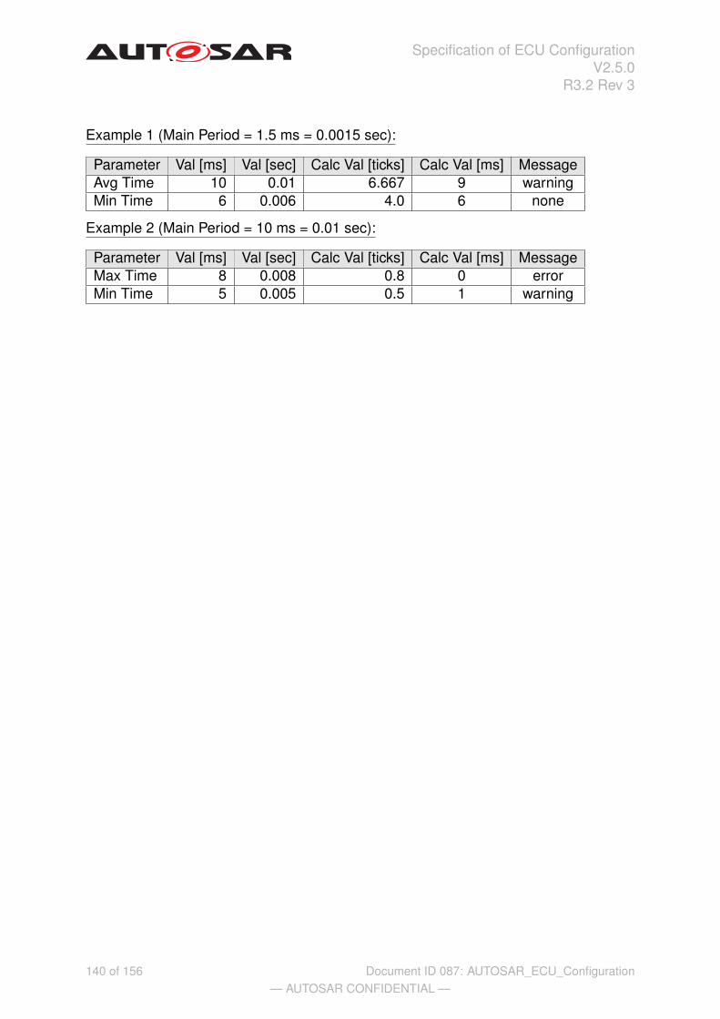
Specification of ECU ConfigurationV2.5.0
R3.2 Rev 3
Example 1 (Main Period = 1.5 ms = 0.0015 sec):
Parameter Val [ms] Val [sec] Calc Val [ticks] Calc Val [ms] MessageAvg Time 10 0.01 6.667 9 warningMin Time 6 0.006 4.0 6 none
Example 2 (Main Period = 10 ms = 0.01 sec):
Parameter Val [ms] Val [sec] Calc Val [ticks] Calc Val [ms] MessageMax Time 8 0.008 0.8 0 errorMin Time 5 0.005 0.5 1 warning
140 of 156— AUTOSAR CONFIDENTIAL —
Document ID 087: AUTOSAR_ECU_Configuration

Specification of ECU ConfigurationV2.5.0
R3.2 Rev 3
5 Rules to follow in different configuration activities
This chapter defines rules relevant for the relation between standardized module def-initions and vendor specific module definitions, rules for building the base ECU con-figuration Description and rules for configuration editors.
5.1 Deriving vendor specific module definitions from standard-ized module definitions
The following rules must be followed when generating the Vendor Specific Mod-ule Definition (abbreviated with VSMD in this chapter) from the StandardizedModule Definition (abbreviated StMD in this chapter). The basic relationship be-tween these two kinds of parameter definitions are depicted in figure 5.1.
Figure 5.1: Generating Vendor Specific Module Definitions (per module)
141 of 156— AUTOSAR CONFIDENTIAL —
Document ID 087: AUTOSAR_ECU_Configuration

Specification of ECU ConfigurationV2.5.0
R3.2 Rev 3
[ecuc_sws_1000] These rules shall be checked by tools that validate that a SW mod-ule implementation conforms to its AUTOSAR specification.
• [ecuc_sws_1001] The lowerMultiplicity of the module in the VSMD mustbe 1 or bigger to what is defined in the StMD. The upperMultiplicity of thatmodule may be equal or less to what is defined in the StMD.
• [ecuc_sws_6001] The shortName of a VSMD module shall be the same as theshortName of the StMD.
• [ecuc_sws_6003] The package structure of the VSMD has to be different than"/AUTOSAR/" so that it is possible to distinguish the standardized from the ven-dor specific module definitions. Example 5.1 shows the difference between theVSMD and StMD. The package structure of the vendor specific CanIf moduledefinition begins with "/VendorX/CanIf" and the package structure of the vendorspecific CanDrv module definition begins with "/VendorY/Can".
Example 5.1
CanIf and CanDrv AUTOSAR standardized XML:
<TOP-LEVEL-PACKAGES><AR-PACKAGE><SHORT-NAME>AUTOSAR</SHORT-NAME>
<ELEMENTS><MODULE-DEF>
<SHORT-NAME>CanIf</SHORT-NAME><CONTAINERS>
<PARAM-CONF-CONTAINER-DEF><SHORT-NAME>CanIfDriverConfig</SHORT-NAME><REFERENCES>
<!--Reference Definition:CanIfDriverRef--><REFERENCE-DEF>
<SHORT-NAME>CanIfDriverRef</SHORT-NAME><DESTINATION-REF DEST="PARAM-CONF-CONTAINER-DEF">
/AUTOSAR/Can/CanGeneral</DESTINATION-REF>
</REFERENCE-DEF></REFERENCES>
</PARAM-CONF-CONTAINER-DEF></CONTAINERS>
</MODULE-DEF><MODULE-DEF>
<SHORT-NAME>Can</SHORT-NAME><CONTAINERS>
<PARAM-CONF-CONTAINER-DEF><SHORT-NAME>CanGeneral</SHORT-NAME><PARAMETERS>
...</PARAMETERS>
</PARAM-CONF-CONTAINER-DEF></CONTAINERS>
</MODULE-DEF>...
142 of 156— AUTOSAR CONFIDENTIAL —
Document ID 087: AUTOSAR_ECU_Configuration

Specification of ECU ConfigurationV2.5.0
R3.2 Rev 3
CanIf VendorX XML:
<TOP-LEVEL-PACKAGES><AR-PACKAGE>
<SHORT-NAME>VendorX</SHORT-NAME><ELEMENTS>
<MODULE-DEF><SHORT-NAME>CanIf</SHORT-NAME><REFINED-MODULE-DEF>AUTOSAR/CanIf</REFINED-MODULE-DEF><CONTAINERS>
<PARAM-CONF-CONTAINER-DEF><SHORT-NAME>CanIfDriverConfig</SHORT-NAME><REFERENCES>
<!--Reference Definition:CanIfDriverRef--><REFERENCE-DEF>
<SHORT-NAME>CanIfDriverRef</SHORT-NAME><DESTINATION-REF DEST="PARAM-CONF-CONTAINER-DEF">
/AUTOSAR/Can/CanGeneral</DESTINATION-REF>
</REFERENCE-DEF></REFERENCES>
</PARAM-CONF-CONTAINER-DEF></CONTAINERS>
</MODULE-DEF>...
The DESTINATION-REF content shall not be changed from "/AUTOSAR/..." in theVSMD.
CanIf VendorY XML:
<TOP-LEVEL-PACKAGES><AR-PACKAGE>
<SHORT-NAME>VendorY</SHORT-NAME><ELEMENTS>
<MODULE-DEF><SHORT-NAME>Can</SHORT-NAME><REFINED-MODULE-DEF>AUTOSAR/Can</REFINED-MODULE-DEF><CONTAINERS>
<PARAM-CONF-CONTAINER-DEF><SHORT-NAME>CanGeneral</SHORT-NAME><PARAMETERS>
...</PARAMETERS>
</PARAM-CONF-CONTAINER-DEF></CONTAINERS>
</MODULE-DEF>...
For all ContainerDefs and ParameterTypes and ConfigReferences definedwithin the ModuleDef in the StMD, it holds:
• [ecuc_sws_1002] Optional elements (with lowerMultiplicity = 0) in theStMD may be omitted from the VSMD. This means that implementations may ormay not support parameters and containers defined as optional in the StMD.
143 of 156— AUTOSAR CONFIDENTIAL —
Document ID 087: AUTOSAR_ECU_Configuration

Specification of ECU ConfigurationV2.5.0
R3.2 Rev 3
• [ecuc_sws_1003] Elements defined with lowerMultiplicity > 0 in StMDmust be present in the VSMD and must not be omitted. lowerMultiplicityin the VSMD must be bigger or equal and upperMultiplicity must be equalor less than in the StMD.
• [ecuc_sws_1034] Elements taken over from the StMD to the VSMD must useexactly the same shortName, since the short name identifies the element. Thisholds for container definitions and individual parameters. The short names ofoptional elements that are omitted from the VSMD must not be used for vendorspecific parameters.
• [ecuc_sws_1035] Elements taken over from the StMD to the VSMD must haveunique uuid in each description. Thus a new uuid must be generated whentaking over an element.
• [ecuc_sws_1005] The origin attribute must not be changed for any parametertaken over from the StMD, even when attributes of the parameter are modified inthe VSMD.
• [ecuc_sws_1006] The defaultValue attributed may be changed (or added, ifmissing).
• [ecuc_sws_1007] The min values specified in the VSMD must be bigger orequal, the max value must be less or equal than the corresponding value specifiedin the StMD.
• [ecuc_sws_1008] Parameter definitions in the StMD may be changed to derivedparameter definitions of the same type. If the implementation has some means toderive a parameter value from other parameters or other templates, it is allowedto add the rules that shall be applied to derive that value.
Parameter defined in the StMD May become in the VSMDBooleanParamDef BooleanParamDef or
DerivedBooleanParamDefIntegerParamDef IntegerParamDef or
DerivedIntegerParamDefFloatParamDef FloatParamDef or DerivedFloatParamDefStringParamDef StringParamDef or
DerivedStringParamDefEnumerationParamDef EnumerationParamDef or
DerivedEnumerationParamDef
• [ecuc_sws_1009] For derived parameters defined in the StMD, the values ofthe calculationFormula and calculationLanguage may change in theVSMD.
• [ecuc_sws_5004] The purpose of calculationFormula is to derive a val-ue/result for a given object from its dependent object. So reference is a must andshould be used to represent the location of the dependent object.
• [ecuc_sws_5005] The calculationFormula should not contain any charac-ters other than alphabets, digits, space and following special characters.
144 of 156— AUTOSAR CONFIDENTIAL —
Document ID 087: AUTOSAR_ECU_Configuration

Specification of ECU ConfigurationV2.5.0
R3.2 Rev 3
" ’ = { } ( ) . + - * /
• [ecuc_sws_5006] The conditional operators in the calculationFormula willbe written as EQ, LT and so on. Given below are different operators and theremeaning
Conditional Operators MeaningEQ Equal ToNE Not Equal ToLT Lesser ThanGT Greater Than ToLE Lesser Than or Equal ToGE Greater Than or Equal To
• [ecuc_sws_1010] A ChoiceContainerDef may include less aggregatedchoices in the VSMD than in the StMD. At least one aggregated choice mustbe included in the VSMD if the ChoiceContainerDef is included, however.
• [ecuc_sws_1011] Additional vendor specific choices (i.e. aggregated Param-ConfContainerDefs) may be added for ChoiceReferenceParamDef in theVSMD.
• [ecuc_sws_1012] A ChoiceReferenceParamDef may include less referencesin the VSMD than in the StMD. At least one aggregated reference must beincluded in the VSMD if the ChoiceReferenceParamDef is included, however.
• [ecuc_sws_1013] Additional vendor specific references may be added forChoiceReferenceParamDef in the VSMD.
• [ecuc_sws_1014] Additional vendor specific parameter definitions (usingParameterTypes), container definitions and references may be added any-where within the ModuleDef in the VSMD.
• [ecuc_sws_1015] The origin attribute of vendor specific additional elementsshall contain the name of the vendor that defines the element.
• [ecuc_sws_2084] For an EnumerationParamDef from the StMD there can beadditional EnumerationLiteralDef added in the VSMD.
• [ecuc_sws_6002] For an EnumerationParamDef from the StMD there can beEnumerationLiteralDefs that are removed in the VSMD.
• [ecuc_sws_5001] Avoid redundant entries of module definition. If the moduledefinition is present in the StMD, the same should not be present in VSMD. Ifparameters in VSMD can be derived from the StMD directly or by computation,these parameters need not be defined in the VSMD.
• [ecuc_sws_5002]Induce VSMD in to the StMD in a simplified manner, so thatthe configuration can be carried out without any disarray.
• [ecuc_sws_5003] The desc in VSMD can be used to specify detailed informa-tion about the respective parameter.
145 of 156— AUTOSAR CONFIDENTIAL —
Document ID 087: AUTOSAR_ECU_Configuration

Specification of ECU ConfigurationV2.5.0
R3.2 Rev 3
• [ecuc_sws_6046] The supported ModuleDef.supportedConfigVariant shall berestricted in the VSMD to the actually supported configuration variants of thisimplementation. This can be a subset of the ModuleDef.supportedConfigVariantin the StMD.
• [ecuc_sws_6047] If the supported ModuleDef.supportedConfigVariant in theStMD is VariantPostBuild and it is supported by the implementation the valuein the VSMD shall be one or both of
- VariantPostBuildLoadable
- VariantPostBuildSelectable
replacing VariantPostBuild. I.e. ModuleDef.supportedConfigVariant of a VSMDshould not contain VariantPostBuild. For compatibility reasons, if it contains Vari-antPostBuild, it is considered as VariantPostBuildLoadable.
• [ecuc_sws_6048] The implementationConfigClass in VSMD must be the sameas in StMD with respect to the selected subset defined by the actually imple-mented ModuleDef.supportedConfigVariant if the scope of the ConfigParameteror ConfigReference in StMD is ECU.
AUTOSAR ECU Processor Tools which processes ECU Configuration Valuesshall report an error if the ConfigurationVariant enumeration in the VSMDof an processed ECU Configuration Values requires a later ConfigurationVa-riant as the AUTOSAR ECU Processor Tools is able to implement.
Figure 5.2 shows an overview about rules, which shall be checked by tools that validatethat a SW module implementation conforms to its AUTOSAR specification. In thisexample three parameters are defined in the StMD.
The multiplicity in each of this parameter definitions specifies how often a parameter isallowed to occur in the ECU Configuration Description. In the VSMD optional elements(with lowerMultiplicity = 0) may be omitted, as it happens with parameter A (1).Parameters defined with lowerMultiplicity > 0 in StMD must be present in theVSMD (2). The upperMultiplicity of parameters in the VSMD must be equal orless than in the StMD (2, 3). New vendor specific parameters may also be added inthe VSMD (4).
The VSMD defines which parameters are available in which container and what kind ofrestrictions are to be respected.
If the upperMultiplicity of a parameter definition in the VSMD is 0, the parametershall not exist in the parameter description( 5). If the lowerMultiplicity of a pa-rameter definition is bigger than 0, the parameter must exist (6). Missing parametersshall be detected by tools (8). Parameters without parameter definitions shall also bedetected (9). The number of parameters in the ECUC Description shall not exceed theupperMultiplicity of the parameter definition in the VSMD (7).
146 of 156— AUTOSAR CONFIDENTIAL —
Document ID 087: AUTOSAR_ECU_Configuration

Specification of ECU ConfigurationV2.5.0
R3.2 Rev 3
Container
Param A
0..1
Standardized MD VSMD
Param B
1..1
Param C
0..*
Container
Param A
0..0
Param B
1..1
Param C
0..255
Param D
1..1
Container
a= 8
b =15
c=16
c=8
Param Value
d=2
e=5
1
3
4
2
5
6
7
8
9
Figure 5.2: Relation between standardized module definition and vendor specific moduledefinition
147 of 156— AUTOSAR CONFIDENTIAL —
Document ID 087: AUTOSAR_ECU_Configuration
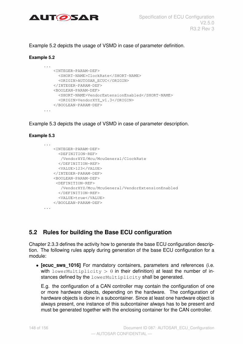
Specification of ECU ConfigurationV2.5.0
R3.2 Rev 3
Example 5.2 depicts the usage of VSMD in case of parameter definition.
Example 5.2
...<INTEGER-PARAM-DEF>
<SHORT-NAME>ClockRate</SHORT-NAME><ORIGIN>AUTOSAR_ECUC</ORIGIN>
</INTEGER-PARAM-DEF><BOOLEAN-PARAM-DEF>
<SHORT-NAME>VendorExtensionEnabled</SHORT-NAME><ORIGIN>VendorXYZ_v1.3</ORIGIN>
</BOOLEAN-PARAM-DEF>...
Example 5.3 depicts the usage of VSMD in case of parameter description.
Example 5.3
...<INTEGER-PARAM-DEF>
<DEFINITION-REF>/VendorXYZ/Mcu/McuGeneral/ClockRate
</DEFINITION-REF><VALUE>123</VALUE>
</INTEGER-PARAM-DEF><BOOLEAN-PARAM-DEF><DEFINITION-REF>
/VendorXYZ/Mcu/McuGeneral/VendorExtensionEnabled</DEFINITION-REF><VALUE>true</VALUE>
</BOOLEAN-PARAM-DEF>...
5.2 Rules for building the Base ECU configuration
Chapter 2.3.3 defines the activity how to generate the base ECU configuration descrip-tion. The following rules apply during generation of the base ECU configuration for amodule:
• [ecuc_sws_1016] For mandatory containers, parameters and references (i.e.with lowerMultiplicity > 0 in their definition) at least the number of in-stances defined by the lowerMultiplicity shall be generated.
E.g. the configuration of a CAN controller may contain the configuration of oneor more hardware objects, depending on the hardware. The configuration ofhardware objects is done in a subcontainer. Since at least one hardware object isalways present, one instance of this subcontainer always has to be present andmust be generated together with the enclosing container for the CAN controller.
148 of 156— AUTOSAR CONFIDENTIAL —
Document ID 087: AUTOSAR_ECU_Configuration
Specification of ECU ConfigurationV2.5.0
R3.2 Rev 3
• [ecuc_sws_1017] For optional containers, parameters and references (i.e. withlowerMultiplicity = 0 in their definition), no instances may be generated.
E.g. the configuration may contain the definition of RX PDUs in a subcontainer.One subcontainer instance is defined for each PDU received. Since there may beno RX PDUs, it is well possible that no container instance needs to be generated.
• [ecuc_sws_1018] For containers with variable multiplicity (i.e. lowerMulti-plicity < upperMultiplicity), any number of instances between lowerand upper multiplicity may be generated. (additional instances may be addedduring Editing of the configuration description).
E.g., continuing the previous example, several instances may be generated if thedefinition of RX PDUs can be derived from the ECU extract of System descrip-tion. If the ECU receives several frames on a CAN bus, at least one RX PDU isnormally present per received frame.
• [ecuc_sws_1019] For the setting of the initial values for configuration parame-ters, the following sources shall be used (in decreasing priority)
– [ecuc_sws_1020] Values fixed by the implementation as defined in the Ven-dor Specific Pre-configured Configuration Description. Since the moduleimplementation fixes those configuration parameters, those values must beincluded in the base ECU configuration description and shall not be changedin later editing.
– [ecuc_sws_1021] Values derived from the ECU extract of the system con-figuration. E.g. for COM stack configuration, the system description providesconfiguration information for bus speed, frame definitions etc, which can betaken over into the ECU configuration description.
E.g. The signal definitions relevant for the COM stack can be derived fromthe ECU extract of system configuration. One container instance with allrelevant parameter values taken from the system configuration will be gen-erated for each signal.
– [ecuc_sws_1022] Values provided by the implementor in the BSWMD inthe Vendor Specific Recommended Configuration Description. Implemen-tors may provide configuration settings in the BSWMD provided with theirimplementation. This allows the implementor to provide the integrator withhis hints which values might be most useful for his implementation of themodule on a specific ECU.
– [ecuc_sws_1023] Default values provided as part of the parameter defini-tion. Since each configuration parameter is defined only once, all instancesof the parameter will have the same initial value when the default values istaken as input to the base configuration.
[ecuc_sws_1024] If no initial value can be derived from any of these sources fora parameter, the parameter will be generated without an initial value.
149 of 156— AUTOSAR CONFIDENTIAL —
Document ID 087: AUTOSAR_ECU_Configuration

Specification of ECU ConfigurationV2.5.0
R3.2 Rev 3
[ecuc_sws_4004] If an existing ECU Configuration Description existand an updated ECU Extract of System Configuration or BSW ModuleDescription is released the existing ECU Configuration Descriptionmust be taken into consideration when updating to a new version of ECU Con-figuration Description, i.e, the Generate Base ECU ConfigurationDescription activity shall consist of a merge functionality. This functionality isoptional since the first time an ECU Configuration Description is gener-ated there is no existing ECU Configuration Description.
5.3 Rules for Configuration Editors
Chapter 2.3.4 describes the methodology for editing configuration parameters. Thefollowing rules apply for a configuration editor supporting the methodology:
• [ecuc_sws_4001] The ECU Configuration Editor shall be able to generate thefiles containing parameters affecting other parameters. That is the xml-files oftype Module Configurations described in chapter 2.3.4.
• [ecuc_sws_4002] The ECU Configuration Editor shall be able to perform asimple merge of ECU Configuration Descriptions as described in chap-ter 2.3.4.
• [ecuc_sws_4003] The ECU Configuration Editor shall be able to work with sub-sets of parameters. The subset shall be any combination of pre-compile time,link-time and post-build time parameters. This feature is to avoid editing wrongkind of parameters.
• [ecuc_sws_4005] The ECU Configuration Editor shall be able to generate andimport files describing a specific aspect of the configuration of a module. Thefiles that shall be generated and imported are ModuleConfigurations. Therationale for this is to support post-build time loadable configuration from a Con-figuration Management perspective. See chapter 2.3.2.3.1.
Following is a list (not complete) of additional requirements which a Configuration Edi-tor shall support:
• [ecuc_sws_2088] When a longName (LONG-NAME in XML) is provided for aconfiguration element the Configuration Editor shall display the content of thelongName this to it’s users.
150 of 156— AUTOSAR CONFIDENTIAL —
Document ID 087: AUTOSAR_ECU_Configuration

Specification of ECU ConfigurationV2.5.0
R3.2 Rev 3
A Possible Implementations for the ConfigurationSteps
A.1 Alternative Approaches
This chapter contains description of alternative approaches and information that is notpart of the AUTOSAR, but can be helpful and give some guidance.
A.1.1 Alternative Configuration Editor Approaches
[ecuc_sws_2124] The ECUC parameter definitions and ECUC descriptions are de-signed to support a variety of different tooling approaches. In the following, the differentapproaches that have been considered during the development of the specification areintroduced. These tooling approaches are supported by ECUC parameter definitionand ECUC description. Other approaches might be consistent with this specification,but have not been considered explicitly.
Tool suppliers have a high degree of freedom in the approach their tools may taketo ECU Configuration. ECU Configuration tools might consist of a single monolithiceditor capable of manipulating all aspects of ECU Configuration, it could be a coretool framework that takes plug-in components to manipulate particular aspects of ECUConfiguration, it might be a set of specialized tools each capable of configuring a par-ticular type or subset of software modules or, probably more likely, software vendorscould supply individual custom tools to configure only the code blocks that they sup-ply (similar to microprocessor vendors providing specialized debuggers for their ownmicros).
Common to the different tool approaches is that each configuration editor must be ca-pable of reading an (possibly incomplete) ECU Configuration Description andwriting back its modified configuration results in the same format. The modificationmay include changed values of ECU Configuration values and added instances of con-tainers with all included ECU Configuration Values (only for containers/parameters withvariable multiplicity).
In every case, the ECU Configuration Description is expected to be the pointof reference, the backbone of the process.
The sections below look at some possible tool forms and identify some of theirstrengths and weaknesses.
151 of 156— AUTOSAR CONFIDENTIAL —
Document ID 087: AUTOSAR_ECU_Configuration

Specification of ECU ConfigurationV2.5.0
R3.2 Rev 3
A.1.1.1 Custom Editors (Informative)
.XML.XML
ECU
Configuration
Description
.h.h
OS
Configuration
Header
.c.c
OS
Configuration
Code
.h.h
COM
Configuration
Header
.c.c
COM
Configuration
Code
.h.h
RTE
Header
.c.c
RTE
Code
Generate
OS
Generate
COM
Generate
RTE
Configure
COM
Configure
RTE
Configure
OS
AUTOSAR
RTE
Configuration
Editor
AUTOSAR
COM
Configuration
Editor
AUTOSAR
OS
Configuration
Editor
AUTOSAR
RTE
Generator
AUTOSAR
COM
Generator
AUTOSAR
OS
Generator
Figure A.1: Custom Editors and Generators
In the custom editors approach as shown in figure A.1, each BSW module is deliv-ered bundled with a custom configuration editor and a generator (E.g. in figure A.1 theAUTOSAR RTE Configuration Editor and AUTOSAR RTE Generator). Thesetools can be optimized to the particular task of configuring one BSW module and wouldlikely be quite powerful. The complex dependencies between the BSW module con-figuration and other configuration items in the ECU Configuration Descriptioncould be expressed and supported in the tool. Each vendor of a BSW module wouldneed to provide a tool. System and ECU engineers would require a large number oftools to deal with the range of BSW modules. Each tool would probably have an in-dividual look and feel and this could increase the training and experience required tobecome proficient.
152 of 156— AUTOSAR CONFIDENTIAL —
Document ID 087: AUTOSAR_ECU_Configuration

Specification of ECU ConfigurationV2.5.0
R3.2 Rev 3
A.1.1.2 Generic Tools (Informative)
.h.h
EEPROM
Configuration
Header
.c.c
EEPROM
Configuration
Code
.h.h
SPI
Configuration
Header
.c.c
SPI
Configuration
Code
.h.h
DIO
Configuration
Header
.c.c
DIO
Configuration
Code
Generate
EEPROM
Generate
SPI
Generate
DIO
Configure
SPI
Configure
DIO
Configure
EEPROM
AUTOSAR
Generic
Configuration
Editor
AUTOSAR
Generic
Generator
AUTOSAR
EEPROM
Generator
.XML.XML
Configuration
Parameter
Definition
for
EEPROM
.XML.XML
Configuration
Parameter
Definition
for
ADC
.XML.XML
Configuration
Parameter
Definition
for
DIO
.XML.XML
ECU
Configuration
Description
Figure A.2: Generic Configuration Editor
An AUTOSAR Generic Configuration Editor as shown in figure A.2 would beable to configure any parameter defined in Configuration Parameter Defini-tions. It would read those definitions and provide a generic interface to edit values forall parameters in the ECU Configuration Description. It would only be able toresolve the relatively simple dependencies explicitly defined in the ConfigurationParameter Definitions. Only a limited number of editors would be required,maybe only one, and the look and feel is less likely to vary greatly between generictools. Training and tooling costs are therefore likely to be lower. Examples of suchtools that already exist or are soon to exist are tresos, GENy, DAvE and MICROSAR,although it should be noted that no ECU Configuration Editors exist at the time of writ-ing this document. On the generation side, either a generic generator may be used, orcustom generators for the individual modules.
153 of 156— AUTOSAR CONFIDENTIAL —
Document ID 087: AUTOSAR_ECU_Configuration

Specification of ECU ConfigurationV2.5.0
R3.2 Rev 3
A.1.1.3 Tools Framework (Informative)
ECU Configuration Editor
ECU Configuration Framework
OS Configuration Plug-In
COM Configuration Plug-In
MCAL Configuration Plug-In
Standardized API
EcuC1
Figure A.3: Framework Tools
The tool framework as shown in figure A.3 is a cross between custom tools and generictools where dedicated configuration steps (OS, COM, MCAL, etc.) are integrated asplug-ins into the common ECU Configuration framework. The heart of the tool would bea framework that provides certain core services such as importing and exporting datafrom standard file formats, maintaining standard internal data structures and providingan HMI to the user. This ensures that the ECU Configuration Description isread, interpreted and written in a defined way. The frame could also monitor and controlthe user / project work flow. It provides a low initial tooling and training investment. Thepower of the approach would be the ability to add plug-in modules that extend the corefunctionality. These would allow very sophisticated features, potentially dedicated toone BSW module, to be added by individual suppliers. Additionally, it would be possibleto add generic plug-ins that addressed a specific aspect of configuration across allBSW modules. This approach relies upon a standard framework: multiple frameworkstandards could lead to high tool costs. An example of this kind of tool is the LabVIEWtest and measurement tool from National Instruments and the Eclipse framework.
A.1.2 Alternative Generation Approaches
As stated before, the ECU Configuration Description is the only configurationsource that stores the configuration parameters for all modules of an AUTOSAR basedECU. However, for several modules such as OS, existing configuration languages havealready been established. Those languages probably will in future still be used fornon-AUTOSAR systems. Thus, modules that are used both for AUTOSAR and non-AUTOSAR systems must support different configuration languages in parallel. Thiscan be implemented in different ways, as shown in figure A.4.
154 of 156— AUTOSAR CONFIDENTIAL —
Document ID 087: AUTOSAR_ECU_Configuration

Specification of ECU ConfigurationV2.5.0
R3.2 Rev 3
.XML.XML
ECU
Configuration
Description
.h.h
OS
Configuration
Header
.c.c
OS
Configuration
Code
Generate
OS
AUTOSAR
OS
Generator
Extract OIL Generate
OSEK OIL
based OS
AUTOSAR
OS to
OIL
Rewriter
OSEK
OS
Generator
OIL
file
{xor}
Figure A.4: Module generator implementation alternatives, example for OS
155 of 156— AUTOSAR CONFIDENTIAL —
Document ID 087: AUTOSAR_ECU_Configuration

Specification of ECU ConfigurationV2.5.0
R3.2 Rev 3
In a fully AUTOSAR based approach, the generator reads in the ECU Configura-tion Description and output the relevant source code directly in one step, sup-ported by a AUTOSAR OS Generator in the example given. To support reuse ofexisting generator tools, this single step can be split into two steps. Then the firstactivity is to extract all OS configuration information from the ECU ConfigurationDescription using an AUTOSAR OS to OIL Rewriter and to store it in the for-mat used by the legacy tools (OIL file in the example chosen). The existing OSEKOS Generator may then read the intermediate format to generate the code. How-ever, the intermediate format must not be changed by any legacy configuration tools,since those changes would possibly make the overall configuration inconsistent, andsince changes would be lost with the next generation of the intermediate format.
[ecuc_sws_1025] Thus, none of the activities (extract, generate) shown in figure A.4must include any engineering step with decisions taken by an engineer. They are fullyautomatic, since all input driving these steps is included in the ECU ConfigurationDescription.
156 of 156— AUTOSAR CONFIDENTIAL —
Document ID 087: AUTOSAR_ECU_Configuration