document resume - eric · document resume ed 258 035 cl 041 763 title antenna construction and...
TRANSCRIPT
DOCUMENT RESUME
ED 258 035 CL 041 763
TITLE Antenna Construction and Propagation of RadioWaves.
INSTITUTION Marine Corps Inst., Washington, DC.REPORT NO MCI-25.15gPUB DATE 5 Dec 84NOTE 173p.PUB TYPE Guides - Classroom Use - Materials tFor Learner)
(051)
EDRS PRICE MF61/PC07 Plus Postage.DESCRIPTORS Adult Education; Behavioral Objectives; Continuing
Education; *Correspondence Study; CourseDescriptions; *Electronic Equipment; IndividualizedInstruction; Learning Activities; Military Training;*Radio; Site Selection; Study Guides; TechnicalEducation
IDENTIFIERS *Antennas; *Radio Operators; Radio Waves
ABSTRACTDeveloped as part of the Marine Corps Institute (MCI)
correspondence training program, this course on antenna constructionand propagation of radio waves is designed to provide communicatorswith instructions in the selection and/or construction of the properantennas) for use with current field radio equipment. Introductorymaterials include specific information for MCI students, a courseintroduction, and a study guide (guidelines to complete the course).The 11-hour course contains four study units. Each study unit beginswith a general objective. The study units are divided into numberedwork units, each presenting one or more specific objectives. Contentsof a work unit include a text and study questions/exercises. Answerkeys are found at the end of each study unit. At the end of thecourse is a review lesson. Topics covered in the study units includeradio communications, propagation of radio waves, antennas, and siteselection and antenna grounding. Appendixes include discussions offield expedient construction and Electromagnetic CompatibilityAnalysis Center capabilities and services. (YLB)
* * * * * * * * * * * * * * * * * * * * * * * * ** ************** * * * * ** * * * * ** * * * * * * * * * * * * * * * ** **
* Reproductions supplied by EDRS are the best that can be made *
* from the original document.***********************************************************************

113. IIMIANTREINT OF ITNIDATIONNATIONAL INSTITUTE OP EDUCATION
EDUCATIONAL RESOURCES INFORMATIONCENTER IERICI
4Tr This document has been *Producedreceived from the person of orgeourdionimposing
I ; Mew changes hewn been made io smprovereproduction quality
. .
Pointe of va* or osmium" Misled on MO dom.Meld do not oeceesenly represent °Medi Nit'Medico of poky
UNITED STATES MARINE CORPSMOMS COOPS OISTOUTI. MAIMS SAIMMOS
SOX $775AOUNSTON. VA. aims 0001
1. ORIGIN
25.15g5 Dec 1984
MCI course 25.15g. Antenna Construction and Propagation of Radio Waves*has been prepared by the Marine Corps ins-Mute.
2. APPLICABILITY
This course is for instructional purposes only.
'fedte61/J. H. D. HOLLADAY
Lieutenant Colonel* U. S. Marine CorpsDeputy Director
3

ACKNOWLEDGMENT
The Marine Corps Institute, Marine Barracks, Washington, D.C. gratefully acknowledgesthe important contributions provided by the following MCI personnel in developing andpublishing the revision of this course:
Course Developer
Officer in Charge
Education Spec4alist
Course Editor
Wordprocessing Technician(s)
Graphics Illustrator(s)
GySgt Anthony L. MILLER
Capt Nark S. MELGESON
Ms. Glenda A. SEALE
Ms Monica L. NOELL
Cpl
Sgt
R.C. MARTIN
. CULP
Pfc SIMMONSLCp1 J. L. McCRART
Sgt G. A. BOWMANCpl R. I. FRANKNOUSER
The Marine Corps Institute gratefully acknowledges the assistance of CommunicationPlatoon, Communication Officer's School, MCDEC, Quantico, Va. in the validation of this course.
The Marine Corps Institute gratefully acknowledges the assistance of Senior Schools,Marine Corps Communications-Electronics School, Marine Corps Air-Ground Combat Center, 29Palms, Ca. in the formal review of this course.

MCIR24i-NRL
INFORMATION
FOR
MCI STUDENTS
Welcome to the Marine Corps Institute training program. Your interest inself-improvement and increased professional competence is commendable.
Information is provided below to assist you in completing the course.Please read this guidance before proceeding with your studies.
I. MATERIALS
Check your course materials. You should have all the materials listed inthe "Course Introduction." In addition you should have an envelope to mailyour review lesson back to MCI for grading unless your review lesson answersheet is of the self-mailing type. If your answer sheet is the pre-printedtype, check to see that your name, rank, and social security number arecorrect. Check closely, your MCI records are kept on a computer and anydiscrepancy in the above information may cause your subsequent activity to gounrecorded. You may correct the information directly on the answer sheet. If
you did not receive all your materials, notify your training NCO. If you arenot attached to a Marine Corps unit, request them through the Hotline (autovon288 -4115 or commercial 202-433-4175).
2. LESSON SUBMISSION
The self-graded exercises contained in your course are not to be returnedto MCI. Only the completed review lesson answer sheet should be mailed toMCI. The answer sheet is to be completed and mailed only after you havefinished all of the study units in the course booklet. The review lesson hasbeen designed to prepare you for the final examination.
It is important that you provide the required information at the bottom ofyour review lesson answer sheet if it does not have your name and addressprinted on it. In courses in which the work is submittel on blank paper orprinted forms, identify each sheet in the following manner:
DOE, John J. Sgt 332-11-999908.4g, Forward ObservationReview "LessonMilitary or office address(RUC number, if available)
Submit your review lesson on the answer sheet and/or forms provided.Complete all blocks and follow the directions on the answer sheet focmailing. Otherwise, your answer sheet may be delayed or lost. If you have tointerrupt your studies for any reason and find that you cannot complete yourcourse in one year, you may request a single six month extension by contactingyour training NCO, at least one month prior to your course completion deadlinedate. If you are not attached to a Marine Corps unit you may make thisrequest by letter. Your commanding officer is notified monthly of your statusthrough the monthly Unit Activity Report. In the event of difficulty, contactyour training NCO or MCI immediately.
1

3. MAIL-TIME DELAY
Presented below are the mail-time delays that you may experience betweenthe mailing of your review lesson and its return to you.
TURNAROUND MCI PROCESSING TOTAL NUMBERMAIL TIME TIME DAYS
EAST COASTWEST COASTFPO NEW YORKFPO SAN FRANCISCO
16 5 21
18 5 23
22 5 27
You may also experience a short delay in receiving your final examinationdue to administrative screening requirld at MCI.
4. GRADING SYSTEM
LESSONS EXAMS
GRADE PERCENT MEANING GRADE PERCENT
A 94-100 EXCELLENT A 94-100B 86-93 ABOVE AVERAGE B 86-93C 78-85 AVERAGE C 78-850 70-77 BELOW AVERAGE 0 65-77NL BELOW 70 FAILING F BELOW 65
You will receive a percentage grade for your review lesson and for thefinal examination. A review lesson which receives a score below 70 is given agrade of NL (no lesson). It must be resubmitted and PASSED before you willreceive an examination. The grade attained on the final exam is your coursegrade, unless you fail your first exam. Those who fail their first exam willbe sent an alternate exam in which the highest grade possible is 65%. Failureof the alternate will result in failure of the course.
5. FINAL EXAMINATION
ACTIVE DUTY PERSONNEL: When you pass your REVIEW LESSON, your examinationwill be mailed automatically to your commanding officer. The administrationof MCI final examinations must be supervised by a commissioned or warrantofficer or a staff NCO.
OTHER PERSONNEL: Your examination may be administered and supervised byyour supervisor.
6. COMPLETION CERTIFICATE
The completion certificate will be mailed to your commanding officer andyour official records will be updated automatically. For non Mariner, yovrcompletion certificate is mailed to your supervisor.
2

7. RESERVE RETIREMENT CREDITS
Reserve retirement credits are awarded to inactive duty personnel only.Credits awarded for each course cre listel in the "Course Introduction."Credits are only awarded upon successful completion of the course. Reserveretirement credits are not awarded for MCI study performed during drillperiods if credits are also awarded for drill attendance.
8. DISENROLLMENT
Only your commanding officer can request your disenrollment from an MCIcourse. However, an automatic disenrollment occurs if the course is notcompleted (including the final exam) by the time you reach the CCO (coursecompletion deadline) or the ACCD (adjusted course completion deadline) date.This action will adversely affect the unit's completion rate.
9. ASSISTANCE
Consult your training NCO if you have questions concerning coursecontent. Should he/she be unable to assist you, MCI is ready to help youwhenever you need it. Please use the Student Course Content AssistanceRequest Form (IS1) -1) attached to the end of your course booklet or call one ofthe AUTOVON telephone numbers listed below for the appropriate course writersection.
288.
PERSONNEL/ADMINISTRATIONCOMMUNICATIONS/ELECTRONICS/AVIATIONNBC/INTELLIGENCEINFANTRY
ENGINEER/MOTOR TRANSPORTSUPPLY/FOOD SERVICES/FISCALTANKS/ARTILLERY/INFANTRY WEAPONS REPAIRLOGISTICS/EMBARKATION/MAINTENANCE MANAGEMENT/ASSAULT AMPHIBIAN VEHICLES
288-3259
288-3604288-3611288-2275
288-2285
288-2290
For administrative problems use the UAR or call the MCI HOTLINE: 288-4175.
For commercial phone lines, use area code 202 and prefix 433 instead of
3

PREFACE
ANTENNA CONSTRUCTION AND PROPAGATION OF RADIO WAVES has been designed to provideprivates through gunnery sergeauts in occupational fields 25 and 28; a source of study on thepropagation of radio waves and the construction and repair of conventional and field expedientantennas.
SOURCE MATERIALS
FM 24-18 Field Radio Techniques, July 19651N-06728A-15 Antenna-Soto, As-t236/GRC, September 1968TM-07505A-14 lams AS-2usi August 1972TM-07508A-14 Antenna 14ZZ59 Qf, May 1974TM-11-5820-348-16 na_qcwon . -292, May 1966TM-11-666 Antennas and Radio rropapation, February 1953COS-0733410,COS-9328-A10
H0.9 HR.14OH 10.3
(CAC-CR-81-019
Conventional and Field Expedient Antennas, 1981he'd Expedient Antennas and Radio wave 'PropagationIndio userttore -Handbook, Sep TAOOptrationsi support to the U. S. Marine Corps, Feb 1981

ANTENNA CONSTRUCTION AND PROPAGATION OF RADIO WAVES
Course Introduction
ANTENNA CONSTRUCTION AND PROPAGATION OF RADIO WAVES is designed to providecommunicators with instructions in the selection and/or construction of the proper antenna(s)for use with current field radio equipment.
ADMINISTRATIVE INFORMATION
ORDER OF STUDIES
Study Unit StudyNumber How urS SukjeAliatter
1 1 Radio Communications2 2 Propagation of Radio Wives3 3 Antennas4 1 Site Selection and Antenna Grounding
Appendix I field Expedient Construction. NOTE: Requiredreading for study unit #3.
Appendix II Electromagnetic Compatbility analysis center(ECAC) capabilities and services
2 REVIEW LESSON2 FINAL EXAMINATION
TT
RESERVE RETIREMENTCREDITS: 3
EXAMINATION: Supervised final examination witheu textbook or notes with a timelimit of 2 hours.
MATERIALS: MCI 25.15, Antenna ConstructionEllommIllondalgtojints.Review lesson and answer sheet.
RETURN OF MATERIALS: Students who successfully complete this course are permitted to keepthe course materials.
Students disenrolled for inactivity or at the request of theircommanding officer will return all course materials.
HOW TO TAKE THIS COURSE
This course contains 4 study units. Each study unit begins with a general objectivewhich is a statement of what you should learn from that study unit. The study units aredivided into numbered .fork units, each presenting one or more specific objectives. Read theobjective(s) and then the work unit text. At the end of the work unit text are studyquestions which you should be able to answer without referring to the text of the work unit.After answering the questions, check you answers against the correct ones listed at the end ofthe study unit. If you miss any of the questions, you should restudy the text of the workunit until you understand the correct response. When you have mastered one study unit, moveon to the next. After you have completed all study units, complete the review lesson and takeit to your training officer or NCO for mailing to MCI. MCI will mail the final examination toyour training officer or NCO when you pass the review lesson.
ii

PrefaceSource materialsCourse introductionTable of contentsStudy guide
TABLE OF CONTENTSWork Unit tut
Study Unit 1. RADIO COMUNICATIONS
Basic components of a radio set 1-1 1.1
Radio waves 1-2 1-2
Carrier waves and modulatio6 1-3 1-4
Summary Review 1-6
Answers to Study Unit #1 Exercises 1-7
Study Unit 2. PROPAGATION OF RADIO WAVES
The atamphere 2-1 2-1
Ground waves, sky waves, and skim zone 2-2 2-3The layers of the ionospere 2-3 2-5Maximum usable frequency (NW) an4 lowest usable frequency (LUF) 2-4 2-8Fading 2-5 2-11Effects of frequency on wave propagation 2-6 2-12Summary Review 2-13Answers to Study Unit #2 Exercises 2-13
Study Unit 3. ANTENNAS
Functions of an antenna and antenna radl4tion 3-1 3.1
Antenna polarization 3-2 3-4Coventional field antennas 3-3 3-8Field expedient antennas 3-4 3-1/Transmission lines 3-5 3-26Summary Review 3-30Answers to Study Unit 03 Exercises 3-30
Study Unit 4. SITE SELECTION AND ANTENNA GROUNDING
Requirlments for site selection 4-1 4-1
Electronic warfare antenna siting 4-2 4-4Grounds and counterpoise 4-3 4-5
Summary Review 4-8Answers to Study Unit /4 Exercises 4-8
Review Lesson R-1
Appendix I
Appendix II
iii

MARINE CORPS INSTITUTE
Welcome to the Marine CorpInstitute correspondence training pro-gram. By enrolling in this course, youhave shown a desire to improve theskills you need for effective Job perfor-mance, and MCI has provided materialsto help you achieve your goal. Now allyou need is to develop your own tnethodfor using these materials to best advan-tage.
'The following guidelines presenta four-part approach to completing yourMCI course successfully!
1. Make a."reconnaissance" ofyour materials:
2. Plan your study lime and choosea good study euvironmentt
3. Study thoroughly and system-atically:
4. Prepare for the fine, eNam.
I. MAKe A "RI:CONNAISSANCE OYOUR MATERIALS
Begin with a look at the courseintroduction page, Read the COURST:iNTRODl'(TION to gel the "hig picture"of the course. Then read the NIATERIALSsection near the hottont or the page tofind out e. hick 11*%tiS) and study aids vonshould have received with the course.If any of the listed materials are miss-ing, see Information for MCI Studentsto find out how :o get them. If you hat eeverything that is listed, you are readyto "reconnoiter" your MCI course.
Read through the tuble(s) of cen.tents or your teNt(s). Note the varioussubjects covered in the course and theorder in which they are taught. Lourthrough the teNtis) awl look at the Mos-
ST
VGUIDE
vii
11
trations. Read a few work unit quea-tions to get an idea of the types that areasked. If MCI provides other studyaids, such as a slide rule or a plottinghoard, familiarize yourself with them.Now, gel down to specifics!
II. PLAN YOUR STUDY TIME ANDCHOOSE A GOOD STI'DY ENVIRON-MENT
From looking over the coursematerials, you should hare some ideaof how much study you will need te cum-plee this course. Hut "some idea" isnot enough. You need to work up apersonal study plate the fnlloviag stepsshould give you some help.
(A) Get a calendar and mark thosedays tirthe a eek uhen you hare timefree for study. Tao study periods perveek, each lasting I to 3 hours, aresilage tied fur completing the minimuminn study units required each mouth byMCI, Of mit so, work and otherschedules are not me same for everyone.The important thing is that you schedulea regular time for AtOdy on the samedays qa each wvel,.
0 Read the OMAt, hi' roductIonpage again. The section mat Iwo, 01I1)E:11OF STI DIES mils you the number orstudy units in the course and the approN-imam number or study hours you willneed to complete each study unit. Duithese study_hours Into your seln.dulF4For eNample. if you set aside two 2 -hourstudy periods etch week and the ORDERor STUDIES estimates 2 study hours foryour first study writ, yon could easilyschedule all col iplete thy first studyunlit iti one study period. On your calen-dar you uould meek Study Unit 1" on the

appropristl day. Suppose that thesecond study unit of your course requires 3 study hours. In that cue. youwould divide the study unit in half andwork on each half tiering a separatestudy period. You would mark yourcalendar accordingly. Indicate on yourcalendar exactly when you plan to workon each study unit for the entire coerse.Do not forget to schedule one or twostudy periods to prepare for the finalexam,
©Stick to your schedule.
Besides planning your studytime, you s'tould also choose a studyenvironment that is right for you. Mostpeople need a quiet place for study, likea library or a reading lounge; otherpeople study better where there is back-ground musiet still others prefer to studyout-of-doors. You must choose yourstudy environment carefully so that itfits your trulkidual needs.
III. STI'DY THOROCOM.Y AND3YS fEMATICA1.1.Y
Armed with a workable scheduleand situated in a good study environmentyou are now ready to attack your coursestudy unit by study unit. To begin, turnto the first peke of study unit 1. On thispage you will find the study unit objective,a statement of what you should be able todo after completing the study unit.
130 NOT begin by reading thework unit questions and flipping throughthe text for answers. If you do so,you will prepare to fail, not pass, thefinal exam. Instead, proceed as fol-lows;
0 Read the objective for thethat work unit and then read the workunit text carefully. Make notes onthe ideas you feel are important.
0 Without referring to the t(INt,anawer the questions at the end of thework wilt.
E.07. Check your answers againstthe correct ones listed at the end ofthe study unit.
® If you miss any of the questions.restudy the work unit until you understandthe correct response.
015n to the net work unit and re-peat steps through 0 until you have com-pleted all the work units In the study unit.
Follow the same procedu: for eachstudy unit of the course. If you haveproblems with the text or work unit questionsthat you cannot solve on your own, askyour section OIC or NCOIC for help. Ifhe cannot aid you, request assistance fromMCI on the Student Course Content Assislance Request included with this course.
When you have finished all the studyunits, complete the course review lesson.Try to answer each question withOat the aid ofreference materials, However, if you do notknow an answer, look it up, When you hovefinished the lesson, take it to your trainingofficer or NCO for ?nailing to MCI. MCIwill grade it and send you a feedback sheetlisting course references for any questionsthat you miss.
IV. PREPARE FOR THE FINAL EXAM
How do you prepare for the finalemon? Polio% these four steps:
0 Review each study unit okileetIveas a summary of what was taught in thecourse.
°Reread all portions or the textthat you found particularly difficult.
°Review all the work unit questions,paying specinl noirmitsi to those you missedthe first time around.
® Study the course reviewlesson, putting Particular attentionto the questions you missed.
If you follow these simplesteps, you shook' do well on thefinal. COOP LUCK I
12

STUDY UNIT i
RADIO COMMUNICATIONS
STUDY UNIT OBJECTIVE: WITHOUT THE Ale OF REFERENCES, YOU WILL IDENTIFY THE BASICCOMPONENTS OF A RADIO SET. YOU WILL ALSO IDENTIFY RADIO WAVES, CARRIER WAVE, ANDMODULATION. LASTLY, YOU WILL IDENTIFY WHAT DETERMINES THE FREQUENCY OF A RADIDWAVE.
Radio is the principal means of communications im many tactical units. It is used forcommand, fire control, exchange of information, administration, and liaison between and withinunits. Radio communications are particularly adaptable to rapidly changing situations. Thisis due to the fact that electromagnetic waves are used to convey signals between communicationterminals whhout the ufe of wires. Communications with highly mobile units such as ships,aircraft, and tanks would be extremely difficult if radio were not available. The use ofradio permits rapid installation and establishment of communications between locationsseparated by great distances and obstacles.
Work Unit 1-1. BASIC COMPONENTS OF A RADIO SET
STATE THE PURPOSC OF A RADIO TRANSMITTER.
STATE THE PURPOSE OF A RADIO RECEIVER.
STATE WHAT AN ANTENNA IS USED FOR
STATE THE PURPOSE OF A POWER SUPPLY.
The basic components of a radio set are the transmitter, receiver, anterria, and powersupply.
a. Transmitter. The device for sending out radio signals is called a transmitter. It
generateTWailites, and radiates a radio frequency (RF) signal. A voice transmitterconsists of an RF generator (oscillator), a power amplifier for increasing the power of thesignal to the desired level, and a modulator for superimposing the intelligence onto the RFsignal.
b. Receiver. The receiver takes the electromagnetic waves and develops an electricalsignal, whirl amplified and demodulated. This procudure is accomplished by minute curt its
entering the receiver from the antenna. A series of amplifiers (each with selective circuits)picks out the band of frequencies corresponding to the signal from a desired station andamplifies it to the desired level. This signal still contains variations corresponding to theoriginal input, either in the furm of frequency or amplitude modulation. A demodulatorremoves the intelligence from the carrier resulting in a signal. This signal is developed inthe audio frequency range. This signal is further amplified to operate a loudspeaker orearphone, thus converting the electromagnetic waves back to an audible signal.
c. Antenna. The antenna provides a means for radiating RF energy into space. At thereceiver-MIN:1On, it provides a means for intercepting (picking up) the radiated RF energy.If the receiver is tuned to the same frequency as the transmitted RF energy (signal),intelligence is made available. In transmission, the antenna operates as a load to thetransmitter. It also operates as a signal source for the receiver in reception (receiving).The gain of an antenna, whether its transmitting or receiving, depends on the design. Thetype of antenna, the site, and the type of ground used are of paramount importance in radiicommunications.
d. Power supply. Power supplies are devices that supply voltage to operate electronicequipment. A power supply is required by both the transmitter and receiver. Power suppliesvary in size and electrical output, ranging from small dry cell batteries to diesel enginegenerators. The operatin3 characteristics of a particular radio set determine the type, size,and output of the associated power supply.
EXERCISE: Answer the following questions and check your responses against those listed atthe end of this 'tudy unit.
1. What is the purpose of a radio transmitter?

2. What is the purpose of a radio receiver?
3. What is an antenna used for?
4. What is the purpose of a power supply?
IM11111..1111==111
Work Unit 1-2. RADIO WAVES
DEFINE RADIO WAVES.
STATE WHAT DETERMINES THE FREQUENCY OF A RADIO WAVE.
:TATE THE FORMULA USED TO FIND THE WAVELENGTH WHEN THE FREQUENCY IS KNOWN.
Radio waves are electromagnetic energy radiating from an antenna. These waves travelnear the surface of the earth and also radiate skyward at various angles to the surface of theearth. (fig 1-1) These electromagnetic waves travel through space at the speed of light,approximately 186,000 miles (300,000 kilometers (KH)) per second.
SKYWAVES
VISTICAL MITINNA
NOOK IVAMIS Filt4.10.o.
Fig 1-1. Radiation of radio waves from a vertical antenna.
The wavelength of a radio wave is the distance traveled by the wave in the period oftime required to complete one cycle. Each complete cycle of two alternations of the wave isone wavelength expressed in meters (fig 1-2). This wavelength may be measured from the startof one wave to the start of the next wave, or from the crest of one wave to the crest of thenext wave. In either case, the distance is the same.
CM124iSI10
Fig 1-2. Wavelength of a radio wave.
1-2 14

The frequency of a radio wave is the number of complete cycles that occur in onesecond. The longer the time of one cycle, the longer the wavelength and the lower thefrequency. The shorter the time of one cycle, the shorter the wavelength and the higher thefrequency. The wavelength of a 2Mliz wave and a 10-MHz wave is demonstrated in fig 1.3.
2 IC
1111VII
1
I VIIto IC
FM24411-14-111
Fig 1-3. Comparison of two waves of different frequency.
Since the frequency of a radio wave is very great, it is expressed in kilohertz (KHz)per second -r megahertz (MHz) per second. One KHz is equal to 1,000 cycles per second, snd 1MHz is equal to 1,000,000 cycles per second.
For practical purposes, the velocity of a radio wave is considered to be constant,regardless of the frequency or the amplitude of the transmitted wave. Therefore, to find thewavelength when the frequency is known, divide the velocity by the frequency.
Wavelength (in meters) 300 000.000 (meters _per secondll(free space) #requency (cycles per secon
300.000frequency (KHz)
300YRIPERFIWFT
To find the frequency when the wavelength is known, divide the velocity by thewavelength.
frequency(cycles per second)
frequency (KHz)
frequency (MK z)
300,000,000wavelength (meters)
300000wavelength (meters)
300wavelength (meters)
Most tactical radio sets operate within the 1.5 MHz to 400 MHz portion of thefrequency spectrum. Radio frequencies are divided into groups or bends of frequencies forconvenience of study and reference. The frequency bands of the radio spectrum are shown intable 1-1.
1-3

OA IMPARTMENT OP IINIOATIONNATIONAL INSTITUTI OF EDUCATION
fOLICATIONAL NTSOURCTS INFORMATION
CINTTR IIRICI0rThk document has been receoduced as
received from the wenn or orsemanionotionsimg 11
i ; Minor chomps have been made to smprove0/modems:in nodal,
.___ .Pante of view or oterount !WOW in this document do not amasser* rematent ottitel MTmotion or who/

The process of superimposing the information upon the carrier is called modulation.This process varies or modifies either the frequency or the amplitude of the carrierwaveform. Both amplitude modulation and frequency modulation methods are used in militaryradio communication systems.
Wheh audio frequency (AF) signals are superimposed on the radio frequency (RF)carrier, additional RE signals are generated. The additional frequencies ate equal to thesum, the difference of the audio frequencies and the radio frequency involved. For example,assume that a 1,000 KH4 carrier is modulated by a 1 KHz audio tone. Two new radio frequenciesare developed, one at 1,001 KHz (the sum of 1,000 and 1 KHz) and the other at 999 KHz (thedifference between 1,000 and 1 KHz). If a complex audio signal is used instead of a singletone, two new frequencies will be set up for each of the audio frequencies involved. The newfrequencies are called sidebands.
Amplitude modulation (AM) is defined as the variation of the RE power output of atransmitter at an audio rate. In other words, the RE energy increases and decreases in poweraccording to the audio (sound) frequencies. In simple terms, amplitude modulation is theprocess of varying the power output of a transmitter (fig 1-5).
Fig 1-5. Amplitude modulated wave.
A radio frequency (RE) carrier is modulated by a single audio tone. In which, twoadditional frequencies are produced. One is the upper frequency, which equals the differencebetween the frequency of the RF carrier and the audio rate. The one higher than the carrierfrequency is the upper side frequency. The one lower than the carrier frequency is the lowerside frequency.
When the modulating signal is made up of complex tones, as in speech, each individualfrequency component of the modulating signal produces its own upper and lower sidefrequencies. These side frequencies occupy a band of frequencies called side bands. The sideband that contains the sum of the carrier and modulating frequencies is called the upper sideband. The side band that contains the difference of the carrier and the modulatingfrequencies is called the lower side band.
The space that a carrier and its associated side bands occupy in the frequencyspectrum is called a channel. In amplitude modulation, the width of the channel (bandwidth)Is equal to twice the highest modulating frequency. Consequently, a 5,000-KHz carrier ismodulated by a band of frequencies ranging from 200 to 5,000 cycles (.2 to 5 KHz), the upperside band extends from 5,000.2 to 5,005 KHz, and the lower side band extends from 4,999.8 to4,995 KHz. Tie bandwidth is then 10 KHz, which is twice the highest modulating frequency (5KHz).
The intelligence of an amplitude-modulated signal exists solely in the side bands, inwhich the amplitude varies according to the strength of the modulating signal.
Amplitude modulation generally is used by radiotelephone transmitters operating in themedium and high frequency portions of the spectrum.
Frequency modulation (FM) is the process of varying the frequency of the carrier wave(fig 1-6).
Fig 1-6. Frequency modulated wave.
1-5
17

Ina frequency-modulated %eve, the frequency varies instantaneously about theunmodulated carrier frequency in proportion to the amplitude of the modulating signal.Therefore, when the modulating signal increases in amplitude, the instantaneous frequencyincrease occurs; when the modulating signal decreases, the frequency decreases.
In an I'M wave, the amplitude of the modulating signal determines the extent ofdeparture of the instantaneous frequency from the center or rest frequency. Thus, theinstantaneous frequency can be made to deviate as much as desired from the carrier frequencyby changing the amplitude of the modulating signal. Even though the modulation frequency isonly a few kilohertz, this deviation frequency may be as high as several hundred kilohertz.The side-band pairs generated by frequency modulation are not restricted, as in amplitudemodulation, to the sum and difference between the highest modulating frequency and the carrier.
The first pair of side-bands in an FM signal are the carrier frequency, plus and minusthe modulating frequency. Additional side-band pairs will appear at each multiple of themodulating frequency. For example, a carrier of 1 MHz is frequency modulated by an audiosignal of 10 KHz. There will be several side-band pairs spaced equally on either side of thecarrier with frequency at 999 KHz/1,010 KHz, 980 KHz/1,020 KHz, 970 KHz/10030 gHz, andcontinuing in the same process. As a result, a frequency modulated signsl occupies a greaterbandwidth than a amplitude-modulated signal.
As indicated above, the FM wave consists of a center or cartier frequency and a numberof side-band pairs. When modulation is applied, the amplitude of the modulation signalincreases in which poor takes place from the center-frequency component and is forced intothe side-band pairs.
The FM signal leaving the transmitting antenna is constant in amplitude, but varies infrequency according to the audio-modulating signal. The signal travels between thetransmitting and receiving antennas; however, it is combined with natural and man-made noisesthat cause amplitude variations in the signal. All of these undesirable amplitude variationsare amplified as the signal passes through successive stages of the receiver until the signalreaches the limiter stage.
The limiter eliminates amplitude variations and passes the Fit signal on to thediscriminator, in which the discriminator is sensitive to variations in the frequency of an RFwave. The resultant constant-amplitude frequency-modulated signal is processed by thediscriminator circuit, which transforms the frequency variations of the signal intocorresponding voltage amplitude variations. These voltage variations reproduce the originalmodulating signal in a reproducing device such as a headset, loudspeaker, or teletypewriter.
Frequent;' modulation generally is used by radiotelephone transmitters operating in thevery high frequency bands.
EXERCISE: Answer the following questions and check your responses against those listed atthe end of this study unit.
1. The wave upon which all information is attached or superimposed for transmissiondefines
2. !Men intelligence has been applied to a carrier, the carrier is said to be
3. The process of varying the RF power output of a transmitter defines
4. The process of varying the frequency of the carrier wave defines
SUMMARY REVIEW
In this study unit, you have learned about the basic components of a radio set. Youhave learned that radio waves are electromagnetic energy which radiate from an antenna. Youhave also learned that a carrier wave acts as a medium for the transmission of informationsignals and that these signals are superimposed upon the carrier wave by means of modulation,either amplitude or frequency.
1-6

Answers to Study Unit #1 Exercises
Work Unit 1-1.
1. To send out radio signals2. The receiver takes the electromagnetic waves and develops an electrical signal,
which is then empltfied and demodulated into an audible signal.3. It provides a mans for radiating RF energy into space and picking up the radiated
RF worst.4. Supplies the voltage needed to operate electronic equipment
Work Unit 1-2.
1. electromagnetic energy radiated from a antenna.2. The nueber of complete cycles that occur in one second3. frequency
Work Unit 1-3.
1. carrier wave2. modulated3. amplitude modulation4. frequency modulation
1-7
19
1

STUD( UNIT 2
PROPAGATION OF RADIO WAVES
STUDY UNIT OBJECTIVE: WITHOUT THE AID OF REFERENCES, YOU WILL IDENTIFY ATMOSPHEREAND THE THREE LAYERS WHICH MAKE UP THE EARTH'S ATMOSPHERE. YOU WILL IDENTIFYGROUND WAVE PROPAGATION, SKYWAVE PROPAGATION, AND SKIP ZONE. IN ADDITION, YOUWILL IDENTIFY THE IONOSPHERE AND TELL WHY IT'S SO IMPORTANT TO LONG RANGE
COMMUNICATIONS. YOU WILL ALSO IDENTIFY MAXIMUM USABLE FREQUENCY (NUF), LOWESTUSABLE FREQUENCY (LUF), AND FADING. LASTLY, YOU WILL IDENTIFY THE EFFECTS THATFREQUENCY HAS ON WAVE PROPAGATION.
Radio communications is not the same at all hours of the day or at all times of theyear. Even though radio waves and the atmosphere above the earth are invisible, theatmosphere plays an important role in radio communications. Things happening on the sun suchas sun spots, being several million miles away, also have a direct effect on communications.Since propagation usually takes place within the earth's atmosphere, it is necessary toestablish a basic understanding of the air around and above us.
Work Unit 2-1. THE AMOSPHERE
DESCRIBE THE ATMOSPHERE.
NAME THE THREE LAYERS WHICH MAKE UP THE ATMOSPHERE.
GIVEN A LIST OF THE ATOMOSPHERE LAYERS AND A LIST OF THE DESCRIPTION, MATCH EACHLAYER WITH ITS APPROPRIATE DESCRIPTION.
The Atmosphere
Wave propagation deals with the properties and the nature of the atmosphere throughwhich radio waves must travel from the transmitting antenna to the receiving antenna. Theatmosphere is a gaseous mass which envelops the earth. It is not uniform, because it varieswith the altitude, geographic location, tine of day or night, season, and year. A knowledgeof the composition and properties of the atmosphere aids in the solution of problems thatarise in planning radio communication paths and in predicting the reliability ofcommunications. The earth's atmosphere is divided into three regions: the troposphere, thestratosphere, and the ionosphere. For an idea of their location and heights above the earthsee figure 2.1.
a. Troposphere. The troposphere is that portion of the earth's atmosphere extending fromthe surface of the earth to a height of approximately 6.8 miles (10 km). Within thetroposphere, the bending of radio waves by refraction causes the radio horizon to exceed theoptical horizon. Troposphere refraction (reletion caused by sudden changes in theCharacteristics of air in a lower atmosphere) affect the received signal at distances beyondthe radio horizon.
b. Stratosphere. The stratosphere is that portion of the earth's atmosphere lyingbetween the troposphere and ionosphere, about 6.8 miles to 30 miles (10 to 48 km) above theearth. The temperature in this region is nearly constant.
c. Ionos here. The ionosphere is that portion of the earth's atmosphere above the lowestlevel at w c onization (spli4ting of molecules into positive and negative charges or ions)of low pressure gasses will affect the transmission of radio waves. It extends from about 30to 250 miles (48 to 402 km) above the earth. The ionosphere is composed of several distinctlayers in which ionization occurs at different levels and intensities.
1

WNW (commas NM too1199$
/9
91099911
1. 90.0
0.MIK 149969
KINOSFIMI I
1.0
tl*
oAleet
outwornmiasmas
istourme smosiraolt
*meanie I! MIMI
009019
w.a. 11*
1.0 v=,
vet ONOimoteVII
a0c
.10/19.
aim
-.e0°Ct.s
STMTOSP11117
110103PHIPI
Lam
stow warettstesnme------_
temeeileas
too
Sem
Lave'
Fig 2-1. The earth's atmosphere.
EXERCISE: Answer the foliating questions and check your responses against those listed atthe end of this study unit.
1. The atmosphere is a
2. The three regions or layers which make up 4' 0 earth's atmosphere are the
, and
Pittchin : Column 1 (items 3 through 5) lists the atmospheric layers. Column 2a rough c) lists the description of the atmospheric layers. itttch each
atmospheric layer in column 1 with the description in column 2. Place youranswers in the spaces provided.
Column 1 Column 2
Atmospheric layers Description
3. Troposphere a. The region of the atmosphere which4. Ionosphere extends from the surface of the earth to
Stratosphere a height of about 6.8 milesb. The region of the earth's atonmsphere
composed by several distinct layersc. The region of earth's atmosphere where
the temperature remains nearly constant2-2
21

Work Unit 2.2. GROUND WAVES, SKY WAIIES. AND SKIP ZONE
DEFINE GROUNDWAVE PROPAGATION.
NAME THE THREE COMPONENTS OF A GROUND WAVE.
STATE WHAT SKY*WAVE PROPAGATION DEPENDS UPON.
DEFINE SKIP ZONE
Ground-Wave Propagation
Ground-wave propagation refers to those types of radio transmission that do not makeuse of waves that have been refracted from the ionosphere. The field intensity of groundwaves depends on the transmitter power, the characteristics of the transmitting antenna, thefrequency of the waves, the diffraction of the waves around the curvature of the earth, theelectrical characteristics (conductivity and dielectric constant) of the local terrain, thenature of the transmission path, and local weather conditions. The following are threecomponents of a ground wave.
a. Direct Wave. The direct wave is that component of the entire wave front that travelsdirectly771ifIriliMansmitting antenna to the receiving antenna (fig 2-2). This component islimited to the line-of-sight distance between the transmitting and receiving antennas, plusthe small distance added by atmospheric refraction and diffraction of the wave around thecurvature of the earth. This distance can be extended by increasing the height of thetransmitting antenna or the receiving antenna (or both).
b. Ground-Reflected Wave. The ground-reflected wave (fig ? -2), is the portion of theradiated wave mit reaches tie receiving antenna after being reflected from the surface of theearth. When both the transmitting and receiving antennas are on or close to the ground, thedirect and ground-reflected components of the ground wave tend to cancel each other.
c. Surface Wave. The surface wave (fig 2-2) which follows the curvature of the earth, isthe cealprtWIffee ground wave that is affected by the conductivity and dielectric constantof the earth.
iM24 III 1 17
Fig 2-2. Possible routes for ground waves.
Sky-Wave Propagation
a. Sky-wave transmission paths. Sky-wave propagation refers to those types of radiotransmission that depend on the ionosphere to provide signal paths between transmitters andreceivers (fig 2-3). Sky -wave transmissions are by far the most Important method for longdistance radio communications.
2-3

1------111/:SI: RAYS PANS TIIROIIM THI:TONONPRIIRK AND ARK LOST.
TRANS-AlITTRO
2.
SKIP
"At4CY.
-,..
(e31
TIMS11 RAYS, WHICHR / RN TO P:A RT I I, PRO -VIM.: COMMUNICATIONS.
Fig 2-3. Various sky-wave transmission paths.
b. Sky-Wave Nodes. The distance at which the wave returns to the earth depends on theheight of the ionized layer and the amount of bending of the path while traversing the layer;the latter depending on the frequency of the wave as compared to the ion density of the layerrequired to refract or bend the wave. Upon return to the eart!os surface, part of the energyenters the earth to be rapidly dissipated, but part is reflected back into the ionosphereagain, where it may reflect downward again at a still greater distance from the transmitter.This means of travel in hops, by alternate reflections from the ionosphere and from thesurface of the earth, may continue, and enables transmission to be received at long distancesfrom the transmitter. Figure 2-4 illustrates this means of travel for paths involving one,two, or three reflections from the ionosphere (single, double and triple hop modes or paths).

IONOSPHI..RE
SINGLE-HOPTRANSMISSION
M ULTIPLEHOP TRANS-MISSION
TRANSMITTER RECEIVER
Fig 2-4. Modes of sky-wave tranmissions.
Figure 2-5 further illustrates this means of tavel and reflection from differentlayers, with the layers represented by line for simplicity. Figure 2-4 also relates theheights of the various ionized layers to actual distances along the earth's surface.
Fig 2-5. Relating reflected waves to distances along earth's surface.
c. Ski Zone. The skip zone is an area where no :'sable signal can be received from agiven transm tter operating at a given frequency. This area is bounded by the outer edge ofthe usable ground-wave propagation and the point nearest: the anterna at which the sky wavereturns to earth--the skip distance. The skip zone a%d its relation to the ground way( areshown in figure 2-6. When the skip distance is within the range of the ground wave, there isno skip zone. In this case, both the sky wave and the ground wave may arrive at the antennawith nearly the same field intensity but a random relative phase. When this occurs, thesky-wave component alternately reinforces and cancels the ground-wave component, causingsevere blasting (Juring reinforcement) and fading (during cancellation) of the signal. Foreach frequency (greater than the critical frequency) at which refraction from an ionospherelayer takes place, there is a skip distance that depends only on the frequency and the stateof ionization. The skip zone, on the other hand depends on the extent of the ground-waverange, and disappears completely if the ground-wave range exceeds the skip distance.
2-5
24

Sky wave noteffectiv
Skip Dia SkIP Z on
tance
Fig 2-8. Skip zone.
EXERCISE: Answer the following questions and check your responses against those listed atthe end of this study unit.
1. Define ground-wave propagation.
2. What are the three components of the ground wave?
a.
b.
c.
3. Sky-wave propagation depends onthe
receivers.
4. Define skip zone.
to provide signal paths between transmitter and
Work Unit 2-3. THE LAYERS OF THE IONOSPHERE
STATE THE GENERAL EFFECT THAT THE "D" REGION HAS ON HIGH FREQUENCY RADIO WAVES.
STATE THE REGION WHICH IS IONIZED AT ALL HOURS OF THE DAY AND NIGHT.
STATE WHAT DETERMINES THE RANGE OF LONG DISTANCE RADIO TRANSMISSIONS.
NAME THE TWO LAYERS OF THE IONOSPHERE WHICH ARE ?4 ST HIGHLY IONIZED.
DEFINE CRITICAL FREQUENCY.
Ionos here. The ionosphere is that portion of the earth's atmosphere containing
ionized gases. ere are four distinct layers of the ionosphere. In the order of increasingheights and intensities, they arc called the "0," "E," "Fl," and "Fr layers. The relativedistribution of these layers is shown in figure 2-7. As may be seen in the illustration, thefour layers are present only during the day when the rays of the sun are directed toward thatportion of the atmosphere. During the the "Fl" and "F2" layers seem to merge into asingle "F" layer, and the "D" and "E" layers fade out. The actual member of layers, theirheights above the earth, and the relative intensity of ionization present in them vary fromhour to hour, day to day, month to month, season to season, and year to year.
a. "D" Re ion. The "D" region exists only during daylight hours and has little effect inbending e pa of high frequency radio waves. The main effect of the "D" region is toattenuate or decrease the intensity of high frequency waves when the transmission path lies insunlit regions.
b. 1E" Re ion. The "E" region is used during the day for high frequency radiotransmission over intermediate distances (less than approximately 1,500 miles). The intensityof this layer decreases during the night; however, and it becomes useless for radio
transmission.23
25

c. "F" Re ion. The "F" region exists at heights up to 240 miles (380 km) above thesurface o the earth and is ionised at all hours of the day and night. There are twowell - defined layers during tWf day and one during the night. At night, the "F" layer lies ata height of about 170 miles (260 ka) and is useful for long-range radio comennication (over1,500 miles (2400 km) ).
d. "Fl" and "F2" Layers. Ouring the day the "F" region splits into two distinct layers,the "Fln layer and the "Fr layer. The "F2" layer is the most useful of all layers fortong-range radio communication, even though the degree of ionization varies appreciably fromday to day as compared with other layers.
PsMOMSOT
F
E
IONOSPHERE
:t';E
iss issetpSMe Wesus We woo Isowsessless.
Sy SislisliklMs Moths*OsON000;
IP14440.1
Fig 2-1. Average layer distribution of the ionosphere.
Ionosphere Characteristics
a. Critical Frequency. The range of long-distance radio transmission is determinedprimarily by the ionization density of each of the layers. The higher the frequency, thegreater density of ionization required to refract radio waves back to earth. The upper ( "f"
and "F") layers refract the higher frequencies because they are the most highly ionized. The"0" layer, which is the least ionized does not refract frequencies above approximately 500KHz. Thus, at any given time and for each ionized layer, there is an upper frequency limit atwhich waves sent vertically upward are reflected directly back to earth. This limit iS calledthe critical frequency. Waves that are directed vertically at frequencies higher than Ur,critical frequency pass through the Ionized layer out into space. All waves directed to theionosphere at frequencies lower than the critical frequency are refracted back to the earth.
b. Critical An le. Radio waves used in communication generally are directed to theIonosphere at some o ique angle called the angle of incidence. Waves at frequencies abovethe critical frequency will be returned, if propagated at angles of incidence lower than thecritical angle. At the critical angle, and at all angles larger than the critical angle, thewave will pass through the ionosphere, if the frequency is higher than the criticalfrequency. As the angle becomes smaller, an angle is reached mt which the wave is bent backto the earth by refraction. The distance between the transmitting antenna and the point atwhich Cie wave first returns is called the skip distance (f10 2 -3),
2 -7
26
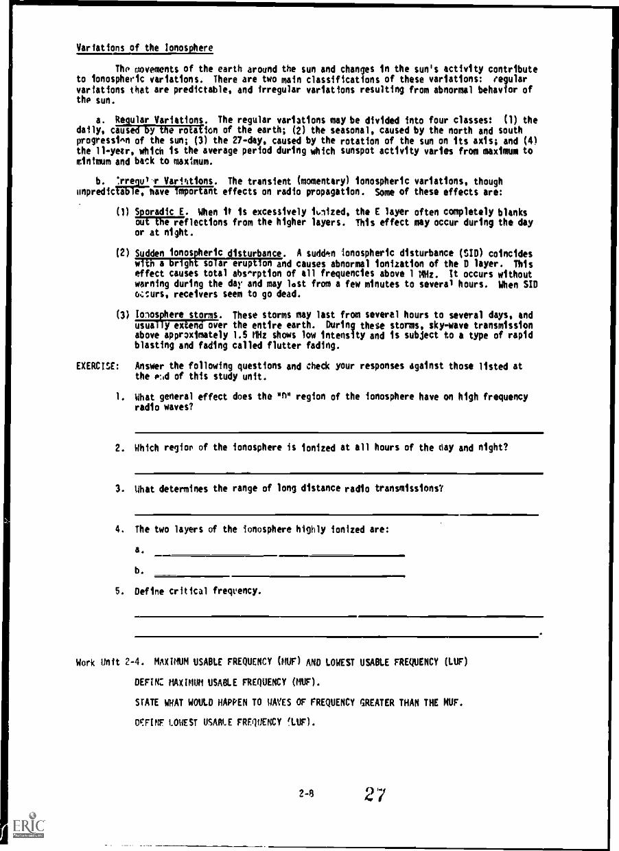
Variations of the Ionosphere
The movements of the earth around the sun and changes in the sun's activity contributeto ionospheric variations. There are two main classifications of these variations: regularvariations that are predictable, and irregular variations resulting from abnormal behavior ofthe sun.
a. Regular Variations. The regular variations may be divided into four classes: (1) thedaily, caused by the rotation of the earth; (2) the seasonal, caused by the north and southprogressi^n of the sun; (3) the 27-day, caused by the rotation of the sun on its axis; and (4)the 11 -year, which is the average period during which sunspot activity varies from maximum tominimum and back to maximum.
b. Irrege-r Vari%tions. The transient (momentary) ionospheric variations, thoughonpredicTiFiThianiFFEERt effects on radio propagation. Some of these effects are:
(1) S oradic E. When it is excessively ioized, the E layer often completely blanksou e reflections from the higher layers. This effect may occur during the dayor at night.
(2) Sudden ionospheric disturbance. A sudden ionospheric disturbance (SID) coincideswith a bright solar eruption and causes abnormal ionization of the D layer. Thiseffect causes total abs.rption of all frequencies above 1 MHz. It occurs withoutwarning during the day and may lost from a few minutes to several hours. When SIDo.:curs, receivers seem to go dead.
(3) biosphere storms. These storms may last from several hours to several days, andusual y ex eno over the entire earth. During these storms, sky-wave transmissionabove approximately 1.5 MHz shows low intensity and is subject to a type of rapidblasting and fading called flutter fading.
EXERCISE: Answer the following questions and check your responses against those listed atthe cid of this study unit.
1. what general effect does the on" region of the ionosphere have on high frequencyradio waves?
2. Which regior of the ionosphere is ionized at all hours of the day and night?
3. What determines the range of long distance radio transmissions?
4. The two layers of the ionosphere highly ionized are:
a.
b.
5. Define critical frequency.
Work Unit 2-4. MAXIM USABLE FREQUENCY (NUF) AND LOWEST USABLE FREQUENCY (LUF)
DEEM MINH USABLE FREQUENCY (MUF).
STATE WHAT WOULD HAPPEN TO WES OF FREQUENCY GREATER THAN THE NUF.
WINE LOWEST USABLE FREQUENCY !LUF).
2-8 27

Maximum Usable Frequency (MU)
An importcnt concept associated with sky-wave propagAtion is called the maximum usablefrequency (MUF). OF is the ilighest frequency for which a radio wave will reflect from anionospheric layer for a given elevation or propagation path. Frequencies higher than the MUFwill penetrate the layer and escape into space.
It is important at this point to discuss propagation predictions and their statisticalnature. The science of predicting ionospheric conditions and the best frequencies to use fora given path is well developed, but subject to the same accuracy problems as prediction of thelocal weather. It is impossible to predict with absolute accuracy what frequency will be bestto use for a given propagation path. It is impossible to predict with reasonable goodaccuracy what the MUF will be for a given communication path at a particular time of day.These predictions are usually based on a statistical reliability of 50 percent . For example,assume that the MUF for a certain propagation path is predicted to be 12 MHz during the timeperiod of 1200 to 1600 hours for the month of November. This actually means that the MUF willbe lower than 12 MHz 15 days of the month and higher than 12 MHz the other 15 days of themonth. The median MUF for the entire month will be 12 MHz. It also means that, on a givenday when the MUF is actually 12 MHZ, frequencies slightly higher than 12 MHZ may be used withgreatly reduced reliability.
When there is a choice of frequencies to use, it is always best to use higherfrequency. This is especially true when communicating over distances greater than about 1,000
km. This reduces absorption from any lower layer and minimizes multi-path fading. However,
it is generally undesirable to operate at or near the MUF, since this frequency is relectedonly 50 percent of the time. To allow for day to day changes in the MUF and the criticalfrequency, it is customary to use a frequency that is about 85 percent of the MUF. This lowerfrequency is known as the frequency of optimum transmission (FOT). It is based on thestatistical fact that it lies below the daily variations of the actual MUF about 90 percent ofthe time. It is not always the frequency for minimum path loss or for minimun fading, andthere are times when a frequency 10 percent lower or higher than the FOT will be better.However, based on statistics, the FOT represents the best choice for a given path length, timeof day, season, and sunspot number, see firire 2-8.
2-9 28

2$
as
2$
DAYfiegso
0
0
4
a
0 OS N 111 MOS 14
$110-PAIN nu or DAY.
SO
Fig 2-8. Typical variation of LUF, FOT, and MUF over a path from London to the Canary Islands
during the month of December.
Lowest Usable Frequency (LUF)
For a given transmitter power, as the operating frequency is decreased, the averagesignal level at the receiver will decrease due to increased ionospheric absorption. Theaverage level of natural atmospheric noise (lightning discharge) and man-made noise(electrical equipment) existing at the receiver location increases at lower frequencies.Thus, if the frequency of transmission is reduced much below the critical frequency, thereceived signal strength decreases while the received noise increases until finally the signalis generally unusable. As the frequency for transmission over any given sky-wave path is
increased, a value will be reached at which the received signal just overrides the level ofatmospheric and other radio noises. This is called the lowest usable frequency (LUF) because
frequencies lower than the LUF are too weak for useful communications. The LUF depends uponthe power of the transmitter, path loss, total noise level at the receiving location,receiving antenna gain and directivity, and noise generated within the receiver itself.Because ionospheric absorption is maximum when the "D" layer reaches its peak, the LUF
generally peaks around noon. A frequency for day use must be chosen sufficiently above theLUF to ensure a reliable signal-to-noise ratio.
EXERCISE! Answer the following questions and check your responses against those fisted at
the end of this study unit.
1. Define maximum usable frequency.
2-10

2. What happens to waves of frequency greater than the MUF?
3. Define lowest usable frequency.
Work Unit 2-5. FADING
DEFINE FADING.
Fading is the periodic increase and decrease of received signal strength. This occurswhen a radio signal is received over a long distance path In the high frequency range. Theprecise origin of this fading is seldom understood. There is little common knowledge of whatprecautions can be taken to reduce or eliminate the troublesome effects of fading. Suggestedmethods for reducing fading are: increasing transmitter power and antenna gain, using two ormore receiving antennas spaced some distance apart both feeding into the same receiver(diversity reception), and proper frequency selection and intelligent use of transmitting andreceiving equipment. Fading associated with sky-wave paths is the greatest single detrimentto reliable communications.
The many types of fading fall into four principal classes: interference,polarization, absorption, and skip fading. Most of the rapid fading in the input to areceiver is a combination of the first two types; the other two are responsible for slowerchanges.
a. Interference Fading,. Interference fading is caused by phase interference of two ormore waves from the same source arriving at the receiver over slightly different paths. If
the paths are of different lengths, and their relative lengths vary for some reoson, such asfluctuations in the height of the ionosphere layers, the relative phases of the waves arrivingover the different paths vary with time, causing alternate reinforcement and cancellation ofthe field Intensity (fig 2-9). Because of irregularities in the ionosphere, one downcomingsky wave is really the summation of a great number of waves of small intensity and of randomrelative phases, and thus the resultant field intensity can vary over wide limits.
Fig 2-9. Fading caused by combination of ground and sky waves.
b. Polarization Fading. Additional variation in the field intensity affecting thereceiving antenna occurs as a result of changes In the state of polarization of the downcomingwave relative to the orientation of the antenna. This variation is called polarizationfading. In general, the state of polarization of the downcoming sky wave is changingconstantly. This is due mainly to the combination, at random amplitudes and phases, of thetwo oppositely polarized components, the ordinary and the extraordinary wave. The
polarization of the downcoming sky wave is generally elliptical. Elliptical polarizationmeans that as the wave travels along the signal
11
path, the electric and magnetic fields-
30

neon in at anqle., to each other t1114 to the direction of propagation, but rotate about thei Anal el tit In 11010 err I t". tOrkSC:r14 fashion instead of remaining constantly in either a
vertical at a bac Itania1 plane with respect to the path, as does the plane polarized wave.This results In random and constantly changing values of the amplitude and orientation of theel ectric feel d with respect to the receiving antenna. The state of polarization of sky wavesvaries more rapidly the higher the frequency, which accounts in part for the rapid fading onthe hillier frequencies.
c, Ah-.0..ption Fading. Absorption fading is caused by short-time variations in the amountof enen,ty-Tiit from the WMy because of absorption in the ionosphere. In general, the periodof this type t f t rdi rhy is much longer than for the other boo types, since the ionosphericabsorption banges slcyoly. the sudden ionospheric disturbance is an extreme case ofthis type of fading, although usually it is classified as an irregular disturbance rather thanas falling. Sometbat similar to this type of fading, although not caused in the ionosphere butby reflections and absorption in objects close to the receiver, is the type of fadingexperienced in receiving a signal while moving along in a vehicle. The fading out of thesignal when the vehicle is passing under a bridge or near a heavy steel structure is caused byabsorption of the wave's energy by the structure. Effects of this sort are involved inso-called dead spots or places where radio reception is particularly difficult. Also,radiation from wires, fences, and steel structures can cause an interference pattern that isrelatively fixed in space, and can be noticed on moving the receiving equipment around. Wherethere are nearby structures hich can cause these effects, care must be exercised in theselection of the receiving site.
d. 4;1(.11 Fadi ru. Skip fading is observed at places near the limit of the skip distance,and is riusedliy to changing angle of refraction. Near sunrise and sunset, when theionization density of the ionosphere is changing, it may happen that the MUF for a giventransmission path fluctuates about the actual operation frequency. When the skip distancemoves out past the receiving station (sometimes called going into the skip) the receivedintensity abruptly drops by a factor of 100 or more, and just as abruptly increases again whenthe skip distance moves in again. This may take place many tines before steady conditions fortransmission are established.
FXERCISF: Answer the following question and check your response against those listed atthe end of this study unit.
1. Define tiding.
Work iblir h. filict% IittQl1ENCY ON WAVE PROPAGATION
l'Aic Ili WA VI PROPAGAT ION THAT 15 EXTREMELY USEFUL FOR C0111UNICATION AT LOW
STATE. 1140 No Mrs OF WAVE PROPAGATION THAT ARE USEFUL AT THE MEDIUM FREQUENCYRAND.
STATE TIIF. RIO TYPES OF WAVE PROPAGATION THAT ARE PRESENT AT THE HIGH FREQUENCYBAND.
STAB: TilE WAVE PROPAGATION THAT PROVIDES THE BEST COMMUNICATIONS AT THE VERY HIGHFREQUENCY RAPID.
WATE THE WAVE PROPAGATION THAT MUST BE USED FOR ALL TRANSMISSIONS AT ULTRA HIGHFREQUENCIES.
The u.iderstanding of the effects of the atmospheric layers described in work units 2-1through 2-5 is complicated further by variations in frequency of the transmitted wave. Thecharacteristics of low frequency propagation are di fferent from high-frequency propagation.the frequencies of propagation usually are classed in ranges shown in table 1-1 for ease ofidentification. There are two principal ways stated earlier in work unit 2-2, in which radiowaves travel from a tranmitter to a receiver by means of ground waves and sky waves.
At low frequetiies (.03 to .3 MHz). the ground wave is extremely useful fortine 9.ror gr Pa ter distance. The ground wave signals are quite stable and show little
in the fiedium-fregnericy hand (.3 to 3.0 MHz), the range of the ground
7.1. 31
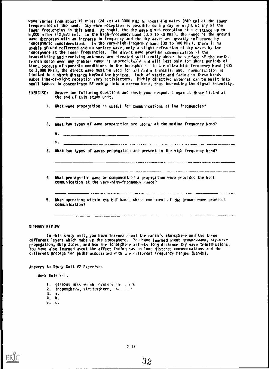
wave varies from about 15 miles (24 km) at 3000 Kilt to about 400 miles (MO kin) at the laterfrequencies of the sand. Sty wave reception h possible during day or night at any of thelower frequencies in this band. At night, the sky wave gives reception at a distance up to8,000 miles (12,810 km). In the high-frequency band (3.0 to 30 MHz ). the range of the groundwave &creases with an increase in frequency and the sky waves we greatly influenced byionospheric considerations. In the very-hi gh.frequency band (30 to 100 Mlle ), there is no
usable ground reflected and no surface wave, only a slight refraction of sty waves by theionosphere at the laver frequencies. The direct wave provide; commun ica t ion if the
transmitting and receiving antennas are elevated sufficiently above the surface of the earth.Transmission over any greater range is unpreditta:le and will last only for short periods ofthe, because of sporadic conditions in the lottosphe,:. In the al trahighfrequency band (300to 3,000 MHz), the direct wave must be used for all radio transmissions. Communication islimited to a short distance beyond the horizon. tack of static and fading in these bandsmakes line-of-sight reception very satisfactory. Highly directive antennas can be built intosmell spaces to concentrate RF energy into a narrow beam, thus increasing the signal intensity.
EXERCISE: Answer tee foliating questions and check your revonses against those listed atthe end vf this study unit.
1. What wave propagation is useful for communications at low frequencies?
2. What two types of wave propagation are useful at the medium frequency band?
a.
b.
3. What two types of waves propagation are present in the high frequency band?
4 What propagation wave or component of a propagation wave provides the bestcommunication at the very-high-frequency range?
5. When operating within the UHF band, iiiich component of the ground wave provides
communication?
SUIIIARY REVIEW
In this study unit, you have learned shout the earth's ahnosphere and the threedifferent layers which make up the atmosphere. Thu have learned about ground-wave, skywavepropagation, skip zones, and hat the ionosphere at facts long distance sky wave transmissions.You have also learned about the affect fading has on long distance communications and thedi fferent propagation paths associated with ,iie di fferent frequency ranges (bands).
Answers to Study Unit #2 Exerc!ses
Work Unit 2-1.
1. gaseous mass which envelops III:, .11.ti,2. troposphere, stratosphere, IN ., ,
3. al.
4. b.
5. o.

Work Unit 2-2.
1. those types of radio transmission that do not take use of waves that have not beenrefracted from the ionosphere.
2. a. Direct waveb. Ground reflected wavec. Surface wave
3. ionosphere4. Pe area where no usable signal can be received from a given transmitter operating
at a given frequency
Work Unit 2-3.
1. Little2. The "r region3. The ionization density of each region within the ionosphere4, a. "E" layer
b. I" layer5. The highest frequency at which waves sent vertically upard are reflected directly
back to earth
Work Unit 2-4.
1. The hiOlest frequency for which a radio wave will reflect from an ionosphericlayer for a given elevation or propagation path
2. The wave will penetrate the layer and escape into space.3. A frequency at which the transmitted/received signal just overrides the level
atmospheric and other radio noises, alleging the signal/intelligence to beunderstood at the receiver.
Work Unit 2-5.
1. The periodic increase and decrease of received radio strength
Work Unit 2-6.
1. Ground wave2. a. Ground wave
b. Sky wave3. a. around wave
b. Sky wave4. Direct wave5. Direct wave
2-14
33
of

STUDY UNIT 3
ANTENNAS
STUDY UNIT OBJECTIVES: WITHOUT THE AID OF REFERENCES, YOU WILL IDENTIFY THEFUNCTIONS OF AN ANTENNA, THE COMPONENTS OF THE RADIATION FIELD AND ANTENNAPOLARIZATION. IN ADDITION, YOU WILL IDENTIFY THE POLARIZATION REQUIREMENTS FORVARIOUS FREQUENCIES AND THE ADVANTAGES AFFORDED WHEN bSING EITHER VERTICAL ORHORIZONTAL POLARIZATION. YOU WILL ALSO IDENTIFY THE CONVENTIONAL FIELD ANTENNASUSED WITHIN THE MARINE CORPS, AND SEVEN TYPES OF FIELD EXPEDIENT ANTENNAS.LASTLY, YOU WILL IDENTIFY THE VARIOUS TYPES OF TRANSMISSION LINES, AND STANDINGWAVES.
The study of antennas is essential to a complete understanding of radio communicationand other electronic systems. In such systems, energy in the form of radio or electromagneticwaves is generated by electronic equipment and fed to an antenna by means of specialtransmission lines. The antenna radiates this energy at the speed of light. Receivingantennas placed in the path of the traveling wave, absorb part of this energy and send it tothe receiving equipment by means of a transmission line.
The ability to obtain successful communication by means of radio waves depends chieflyon radio wave and the factors affecting its successful propagation.
Work Unit 3-1. FUNCTIONS OF AN ANTENNA AND ANTENNA RADIATION
STATE THE FUNCTION OF A TRANSMITTING ANTENNA.
STATE THE PURPOSE OF A RECEIVING ANTENNA.
STATE WHICH FIELD IS RADIATED BEYOND THE TRANSMITTING ANTENNA.
NAME THE TWO FIELDS/COMPONENTS WHICH MAKE UP THE RADIATION FIELD.
NAME THE FIELD WHICH IS FORMED FROM THE ELECTRIC AND MAGNETIC COMPONENTS OF THERADIATION FIELD.
Functions of Antennas. The function of a transmitting antenna is to convert theouptput power de-livered by a radio transmitter into an electromagnetic field which radiatesthrough space. Therefore, the transmitting antenna converts energy having one form to energyhaving another form. The receiving antenna makes the energy conversion in the oppositedirection. The function of the receiving antenna is to convert the electromagnetic field thatsweeps by it into energy that is delivered to a radio receiver. In transmitting, the antennaoperators as the load for the transmitter; in receiving, it operates as the signal source for
the receiver.
Antenna Radiation. When power is delivered to an antenna, two fields are set up bythe fluctuating energy: one is the induction field which associates with the stored energy andthe other is the radiation field which moves out into space at nearly the speed of light. Atthe antenna, the intensities of these fields are high and proportional to the amount of powerdelivered to the antenna. At a short distance from the antenna, and beyond, only theradiation field remains. This radiation field is composed of an electric component and amagnetic component.
The electric and magnetic fields (components) radiated from an antenna form theelectromagnetic field, and this field is responsible for the transmission and reception ofelectromagnetic energy through free space. Thus, the radio wave may be described as a movingelectromagnetic field having velocity in the direction of travel, and with components ofelectric intensity and magnttic intensity arranged at right angles to each other (fig 3-1).

1,0004 attatt 44,44,0st tato
/Ist
MO -'WM
wiz
Fig 3-1. Components of electromagnetic waves.
Antenna Radiation Patterns. The energy of radio signals radiated by an antenna formsan electromagnetic Field having a definite pattern, depending on the type of antenna used.This radiation pattern is used to show both range and directional characteristics of anantenna. A vertical antenna theoretically radiates energy equally in all directions. In
practice, however, the pattern is usually distorted by nearby obstructions or terrain features.
The full or solid radiation pattern is a three-dimensional figure that looks somewhatlike a doughnut, with a transmitting antenna in the center (fig 3-2). The top pattern in thefigure is a quarter wave vertical antenna and the bottom pattern is a half-wave horizontalantenna a 1/2-wavelength above the ground. The general method of illustrating a radiationpattern, however, is by cross-section of the full pattern showing only one particular plane
(fig 3-3). The top pattern of the figure is a half -wave horizontal antenna a 1 /4- wavelengthabove the ground and the bottom pattern is a half-wave horizontal antenna, 1/2- wavelengthabove the ground.
33-2

ilivi> l'1; A 1074 r,, I.? o --,"' ;cort6r. 1 i;t.. i ..4 ...e infir0 .':t... As. ' 4 .11'' .0:APP 11. ;.Y.' 4.A. ;
$ . aft It'i ft :%.:Jrt;x!..idt tilliftikLik' NI- '
j,...."...1..mi......
Jo ,/
tql
'ANTENNA
fig 3-2. Solid radiation patterns from quarter-wave and half-wave antennas.
36

tf3 4
f0414.10-114
Fig 3.3. Cross-sectional representation of radiation pattern in one plane.
EXERCISE: Answer the following questions and check your responses against those listed atthe end of this study unit.
1. What is the function of a transmitting antenna?
2. What is the purpose of a receiving antenna?
3. Which of the two fields set up by fluctuating energy is radiated out into space?
4. The radiation field is composed of an component anda component.
5. The electric and magnetic fields (components) radiated from an antenna. formthe field.
Work Unit 3-i. ANTENNA POLARIZATION
STATE HOW THE POLARIZATION OF A RADIATED WAVE IS DETERMINED.
NAME THE TWO TYPES OF ANTENNA POLARIZATION.
STATE THE ANTENNA POLARIZATION TO OE USED WHEN WORKING WITH MEDIUM AND LOWFREQUENCIES.
3.4

STATE WHY IT'S BETTER TO USE HORIZONTALLY POLARIZED ANTENNAS AT HIGH FREQUENCIES.
STATE WHICH TYPE OF POLARIZATION TO BE USED AT VERY-HIGH AND ULTRA-HIGHFREQUENCIES.
GIVEN A LIST OF ADVANTAGES FOR THE VERTICAL AND HORIZONTAL POLARIZATION AND A LISTOF THE TYPES OF ANTENNA POLARIZATION, MATCH EACH ADVANTAGE WITH ITS APPROPRIATEANTENNA POLARIZATION.
Polarization. Polarization of a radiated wave is determined by the direction of thelines orce up the electric field. If the lines of electric force are at right
angles to the surface of the earth, the wave Is said to be vertically polarized (fig 3-4). If
the lines of electric force are parallel to the surface of the earth, the wave is said to behorizontally polarized (fig 3-5).
A single-wire antenna is used to extract energy from a passing radio wave. Thereforemaximum pickup results, if the antenna is so oriented, that it lies in the $4,10 direction asthe electric-field component. .Thos, a vertical antenna is used for efficient reception ofvertically polarized waves and a horizontal antenna is used for the reception of horizontallypolarized waves. In some cases, the field rotates as the wave travels through space. Under
these conditions, both horizontal and vertical components of the field exist and the wave issaid to have elliptical polarization.
as or TRAM-,la
.6O
4.
a
. ;"; .6. . ..(AWN 6 66 :t. 6a..
Fig 3-4. Vertically polarized signal.

OIRECTION OF TRAVEL -r:\1 rrr
--r/1/\ ELEGTO0C FIELD ,\
VI ill , ,,
r
4"%likkiArtoosiSIGNAL VOLTAGE
I I
"-
.
ELEGTRIC FIELD
.FM24.06-1-210
Fig 3-5. Horizontally polarized signal.
Polarization requirements for various frequencies. At medium and low frequencies, ground-waveVITIlmission is used extensively, for this reason, it is necessary to use verticalpolarization. Vertical line: of force are perpendicular to the ground, and the radio wave cantravel a considerable distance along the ground surface with a minimum amount of attenuation(loss). Because the earth acts as a fairly good conductor at low frequencies, horizontallines of fnce are shirted out and the useful range with horizontal polarization is limited.
At high frequencies with sky-wave transmission, it makes little difference whetherhorizontal or vertical polarization is used. The sky wave reflected by the ionosphere,arrives at the receiving antenna elliptically polarized. Therefore, the transmitting andreceiving antennas can be mounted either horizontally or vertically. Horizontal antennas arepreferred because they can be made to radiate effectively at high angles and have inherentdirectional properties.
With frequencies in the very-high or ultra-high range, either horizontal or verticalpolarization is satisfactory. Since the radio wave travels directly from the transmittingantenna to the receiving antenna, the original polarization produced at the transmittingantenna is maintained throughout the travel of the wave to the receiving antenna. Therefore,if a horizontal half-wave antenna is used for transmitting, a horizontal antenna must be usedfor receiving. If a vertical half-wave antenna iS used for transmitting, a vertical antennamust 'ue used for receiving.
Advantage, of Vertical Polarization. Simple, vertical half-wave antennas can be usedto provide omni=directionaT communication which has the ability to coumunicate with a movingvehicle. When antenna heights are limited to 10 feet or less over land, as in vehicularinstallation, vertical polarization provides a stronger received signal at frequencies up toabout 50 MHz. From approximately 50 to 100 MHz, there is only a slight improvement overhorizontal polarization with antennas at the sane height. The difference in signal strengthabove 1100 MHZ is negligible.
3-6

For transmission over sea water, vertical polarization is decidedly better than
horizontal when antennas are below approximately 300 feet at 30 MHz. You would only need 50
feet at 115 MHz and still lower at the high frequency. Therefore, an ordinary antenna at mastheights, such as 40 feet, vertical polarization is advantageous for freguencie, less thanabout 100 MHz.
Radiation using vertical polarization is less affected by reflections from aircraftflying over the transmission path. With horizontal o..,larization, such r?flections cause
variations in the received signal strength. This factor is important in 'orations whereaircraft traffic is heavy.
With vertical polarization, less interference is produced or ',liked up because ofstrong VHF and UHF broadcast transmission and reception (television and frequency modulation),all of which use horizontal polarization. This factor is important when an antenna must belocated in an urban area having several television and fm broadcast stations.
Advanta es of Horizontal Polarization. A simple horizontal half-wave antenna isbi-direc .ona . This charatiT s useful, if it is desired to minimize interference fromcertain directions.
Horizontal antennas are less apt to pick up man-made interference, polarizedvertically.
When antennas are located near dense forest, horizontally polarized waves suffer lowerlosses than vertically polarized waves, especially above about 100 MHz.
Small changes in antenna location do not cause large variations in the field intensityof horizontally polarized waves when antennas are located among trees or buildings. Whenvertical polarization is used, a change of only a few feet in the antenna location may have aconsiderable effoct on the received signal strength. This is the result of interferencepatterns which produce standing waves in space when spurious reflections from trees orbuildings occur.
Since the interference patterns will vary even when the frequency is changed by only asmall amount, considerable distortion may occur when complex types of modulation are used, aswith television signals or with certain types of pulse-modulation systems. Under theseconditions, horizontal polarization is preferred.
When simple half-wave antennas are used, the transmission line, usually vertical, isless affected by a horizontally mounted antenna. By keeping the antenna at right ingles tothe transmission line and using horizontal polarization, the line is kept out of the directfield of the antenna. As a result, the radiation pattern and electrical characteristics ofthe antenna are practically unaffected by the presence of the vertical transmission line.
Receiving Antennas. Vertical receiving antennas accept radio signals equally from allhorizontal directions, just as vertical transmitting antennas radiate equally in allhorizontal directions. Because of this characteristic, other stations operating on the sameor adjacent frequencies may interfere with the desired signal and make reception difficult orimpossible. However, reception of a desired signal can be improved by using directionalantennas.
Horizontal half-wave antennas accept radio signals fro.. all directions other than thetwo directions in direct line with the ends of the antenna. Thus, when only one signal is
causing interference, or when several intlrfering signals are coming from the same direction,interference can he eliminated or reduced by changing the antenna installation so that eitherend of the antenna points directly at the interfering station.
EXERCISE; Answer the following questions and check your responses against those listed atthe end of this study unit.
1. How is the polarization of a radiated wave determined?
2. What are the two types of antenna polarization?
a.
h.
..1.1.1.1
40

3. What kind of antenna polarization should you use when working with low and mediumfrequencies?
4. Why is it better to use horizontally polarized antennas it high frequencies?
5. Which type(s) of polarization should be used at very-high and ultra-highfrequencies?
Matchin : Column 1 (6 through 9) lists advantages of vertical and horizontalpo r t tion. Column 2 (a and b) lists the two types of antenna polarization.Match the specific advantage in column 1 with that type of polarization whichprovides the advantage in column 2. Write your answers in the spaces provided,
Column 1 Column 2
Advantages of vertical and horizontalpotamation
6. Useful in minimizing interference a. Verticalfrom certain directions
b. Horizontal
.111110.11MI
Types of antenna polarization
7. Useful when communicatingiith moving vehicles
C. is somehwhat less affected by air-craft flying over the transmissionpath
9. Suffers lower losses when located neardense forests
Work Unit 3-3. CONVENTIONAL FIELD ANTENNAS
DESCRIBE ANTENNA EQUIPMENT RC-292.
DESCRIBE ANTENNA AS-2851/TR.
STATE WHICH ANTENNA SYSTEM CONSIST OF A COLLAPSIBLE FOLDING LOG PERIODIC ANTENNASHAPED IN THE FORM OF A SQUARE.
STATE WHICH ANTENNA SYSTEM IS DESIGNED TO PROVIDE SHORT-RANGE SKY-WAVE PROPAGATION.
Antenna Equipment RC-292 (fig 3-6) is an .'evated, wide band, modified ground planeantenna designed to operate with and increase ,e 4 'rating range (FM radios 50 to 200percent) of various radio sets. The antenna Prtical radiating element. Three groundplane elements are installed at a 1420 angle t the antenna (vertical element) to act as acounterpoise (artificial ground). The lengths A 4ie elements can be preadjusted for bestperformance with each type of radio. The ante d. elevated on a 30-foot sectional mast,increasing the line-of-sight distance to the ho.4ton, It is held in place by guy ropes andground stakes old is connected to the radio by a 68-foot 50-ohm coaxial cable. This antennaequipment is designed for hand or vehicular transportation, and when disassembled is packed ina canvas roll (CW-50/TRC-7).
The antenna requires no tuning in operation and provides a radiation pattern that isomnidirectional it the horizontal plane. However, the lengths of the antenna elements mustbe preadjusted for the different frequency ranges of the radio set with which it is beingused. This !s done by changing the number of mast sections in the antennas and ground planeelements. The swivel ground stake on which the mast is supported makes it easy to lower theantenni4 and make the necessary changes. The RC-292's overall frequency range is from 20-75.95MHz. It can be erected by two men in approximately 15 minutes. Its maximum height is 41 1/2ft and minimum height is 37 ft. Its total weight including spares is 48 lbs. For moreinformation on the RC-292, see TM 11-5820-348-15 or NCI correspondence course number 25.30,VHF Field Radio Equimet.
3-8
41Jilillii

Fig 3-6. Antenna equipment RC-292.
Antenna AS-2851/TR
Description, Physical and Functional. the Antenna AS-2851/TR (fig 3-7) is aman-transportable tactical log periodic antenna which provides transmission nd receptioncapabilities over the 3G to 76 Milt frequency range. It can be assembled or disassembled bytwo men in less than 10 minutes. See table 3-1 for reference data.
3-9
42

Table 3-1. Reference Data
Power Handling CapabilityFrequency RangeInput Impedance
VSWRForward Gain
Front to Back Ratio
Overall HeightOperating Temperature RangeHumidity LimitsMaximum Wind SurvivalLongest Element Tip to TipBoom LengthHeightPolarization
65 watts average 135 PEP30 to 76 MHz50 ohms unbalanced2 to 1 maximum4dbi 30 to 35 MHzI.5dbi 35 to 76 MHz4db at 30 MHz7.5db at 50 MHz10db at 76 MHz20 feet-600 to 1500Fto 95%
60 knots no ice16'-8"
C-0"Approx. 30 lb.Vertical or Horizontal
a. Physical Description. The following paragraphs describe the major components of theAS-2851/7k.
(1) Antenna Array Assembly. The antenna array assembly consists of a folding boomwhich supports a planar array of seven log periodic dipole elements. Whencollapsed and folded for storage, the antenna array assembly fits into a48-inch-long by 8-inch-wide space. A polarization block and polarization changerope permit the polarization of the antenna to be changed without lowering ordisassembling the mast.
(2) Mast Assembl . The mast assembly consists of six separate mast sections whichsuppor ne antenna array assembly at its fully extended height of 20 feet. The
upper metal mast section contains a collar haring for attachment of the guy cableassembly. The upper two mast sections are constructed of fiberglass to preventdistortion of the antenna radiation pattern.
(3) Mast Base Assembly. The mast base assembly consists of a metal plate with ahinged mast base clamp to permit the mast to be assembled horizontally and tiltedup into position. Two wing nuts on the base clamp permit azimuth adjustment. Ametal tab is provided for attachment of the polarization caange rope.
(4) Gu Rin Assembl . This assembly consists of a guy ring, three dielectric ropeguy nes am ensioning devices of sufficient strength to hold the antennaupright in a 60-knot wind.
(5) Antenna Guy Hold-downs. Five metal spike-shaped stakes, approximately 9 incheslong, are provided to anchor the base plate and three guy lines.
(6) Harmer. A small machinist's type hammer with approximately 1-pound head weight is
(7) Cable Assembly. The cable assembly consists of 75 feet of RG-58C/U coaxial cable
r7iTaferCiEhera UG-88 B/U connectors on each end. A strain relief snap on theupper end of the cable attaches to the antenna boom to eliminate strain on theconnector caused by the weight of the dangling cable.
(8) Antenna Case. All components of the AS-2851/TR are packed in a rollout type
canvas case with straps to position components securely. A weatherproof pictorialoperating and assembly Instruction plate is affixed to the inside of the case.
b. Functional Description. This antenna is employed as a lirectional, lightweight,man-transportable antenna far use with tactical VHF FM radio equipment. It is a component of
the WI,. Terminal Set AH/TRC-166.
3-10 4

Fig 3-7. Overall view of AS-2851/1R antenna .ystem.
3-11
44

For more information on the AS-2851/TR, see T11-07505A-14 or MCI correspondence coursenumber 75.31, VHF Multichannel Radio Equipment.
Antenna System AS-22360C
The AS-2236/GRC Antenna System (fig 3-8) is a portable, easily assembled unit whichprovides transmission and reception capabilities over the 30 MHz to 76 MHz frequency range.The system consists of a collapsible folding log periodic antenna shaped in the form of asquare, an RG-8A/U 53 ohm RF cable assembly, a tripod assembly, six metallic mast sections,two dielectric mast sections, a guying assembly, nine stakes, and a hammer, packaged in threeseparate canvas carrying bags. Assembly of the system is accomplished by two men in less than10 minutes under variable terrain and soil conditions. Built primarily for point to pointcommunication, the antenna receives maximum strength signals at its front while signalsreceived at the sides or the back are diminished. This directional characteristic is used toincrease signal strength of a desired station while reducing signal stength of possibleinterfering stations. Azimuth direction of the antenna may be changed without moving thetripod legs or guy lines. In addition, the antenna may be mounted on the mast in either thehorizontal or the vertical position, thereby providing a choice of polarization.
Table 3 -p. The Reference Data for the Antenna System AS -2236 /GRC
Packaging Dimensions
System Weight
Erected Height
Assembly Time
Max. Wind Speed
Frequency Range
Polarization
Max. Power
3-12
Three packs, each 48 inches long Max.
Three packs, eat,4 35 pounds Max.
35-feet Max.
Ten udnutes Max. (two men).
60 knots (guy lines secured and tensioned).
30 MHz to 76 MHz
Vertical or Horizontal
65 watts CW.

Fig 3-8. The AS-2236/GRC antenna system.
3-13
46

For more information on the Antenna System AS-2236/GRC, see TM-06728A-15 or NCIcorrespondence course number 25.31, VHF Multichannel Radio Equipment.
Antenna AS-2259/GR
The AS-2269/0R Manpack HF Antenna (fig 3-9) is essentially a dipole antenna fed with alow-loss, foam-dielectric, coaxial mast that also serves as a support structure. The dipolesystem uses a set of crossed sloping dipoles positioned at right angles to each other.Physically the antenna consists of eight lightweight coaxial mast sections and four radiatingelements that also serve as guys. The antenna is transported in a canvas pack similar to atool roll. The total packed weight of the antenna is 14.7 pounds. Erection is accomplishedby two men in 5 minutes without the use of any tools.
The AS-2269/0R antenna is designed to provide high-angle radiation (near verticalincidence) to permit short-range skywave propagation over communication circuits varying from0 to 300 miles. The AS-2259/0R may be used with tactical HF radios that tune a 15-foot whipantenna, such as the AN/PRC-47. The frequency range of the antenna is 2.0 to 30.0 MHz andmaximum RF power capacity is 1000 watts pep, or average.
Leading particulars and summary of equipment fete the AS-2259/GR are listed in tables
3-3 and 3-4. Personnel should become thoroghly familiar with data and procedures containedin the entire instruction manual before working on or using the antenna.
For more information on the Antenna AS-2259/014 see TM- 07508A -14 or MCI correspondencecourse number 25.32, HF/UHF Field Radio Equipment.
3-14
4 7

4
Fig 3-9. AS-2259/6R manpack HF antenna.
3-15
48

Table 3-3. Leading Particulars
ITEM LEADING PARTICULAnS
Electrical Characteristics:
frequency range
Polarization
RF power capacity
Input impedance
Radiation pattern
Azimuth
Elevation
Gain:
Physical Characteristics
Wind and ice
Height erected
Land area required
Erection time
Packed weight
2.0 to 30.0 MHz
Horizontal and vertical simultaneously.
1000 watts pep or average.
Compatible with output of radios using15 -foot whips, such as the AN/PRC-47.
Omnidirectional.
Near vertical incidence.
Similar to a dipole mounted horizontally,10 feet above same type ground.
Survives 60 mph wind with no ice.
15 feet.
60 by 60 feet.
Two men, 5 minutes; one man 15 minutes.
Less than 14.7 pounds.
3-16

MILITARYTYPE NO.
AS-2259/GR
MX -9313/GR
Table 3-4. Summary of Equipment
DESCRIPTION OF EQUIPMENT
An antenna which may be used directly withHF manpack radios that tune a 15-foot whipantenna, such as the AN/PRC-47. Theantenna is rated at 1000 watts pep oraverage RF power.
An adapter fitting for mounting the antennaon vehicles or shelters equipped with HFradios. Adapts Antenna AS.2259/4R to theAN/TRC-75, AN/MRC-83, AN/MRC-87, AN/TSC-15,and similar radios employing 1-inch 8threads per inch whip bases and automaticcouplers.
EXERCISE: Answer the following questions and check your responses against those listed atthe end of this study unit.
1. Describe antenna equipment RC-292.
00..1001,
2. Describe antenna AS-2351/TR.
3. Which antenna system consists of a collapsible folding log periodic antenna shapedin the form of a square?
4. Which antenna system is designed to provide short-range skywave propagation?
Work Unit 3-4. FIELD EXPEDIENT ANTENNAS
RIVEN A LIST OF THE VARIOUS FIELD EXPEDIENT ANTENNAS MITH ILLUSTRATIONS, MATCHEACH ANTENNA WITH THE APPROPRIATE ILLUSTRATION.
STATE MON THE LONG WIRE ANTENNA'S BEST PERFORMANCE IS OBTAINED.
STATE WHAT HAPPENS TO A HALF-RHOMBIC ANTENNA WHEN TERMINATED IN A RESISTOR.
STATE THE LENGTH FOR WHICH THE VERTICAL AND GROUND PLANE ELEMENTS FOR AN EXPEDIENTGROUND PLANE ANTENNA SHOULD BE CUT.
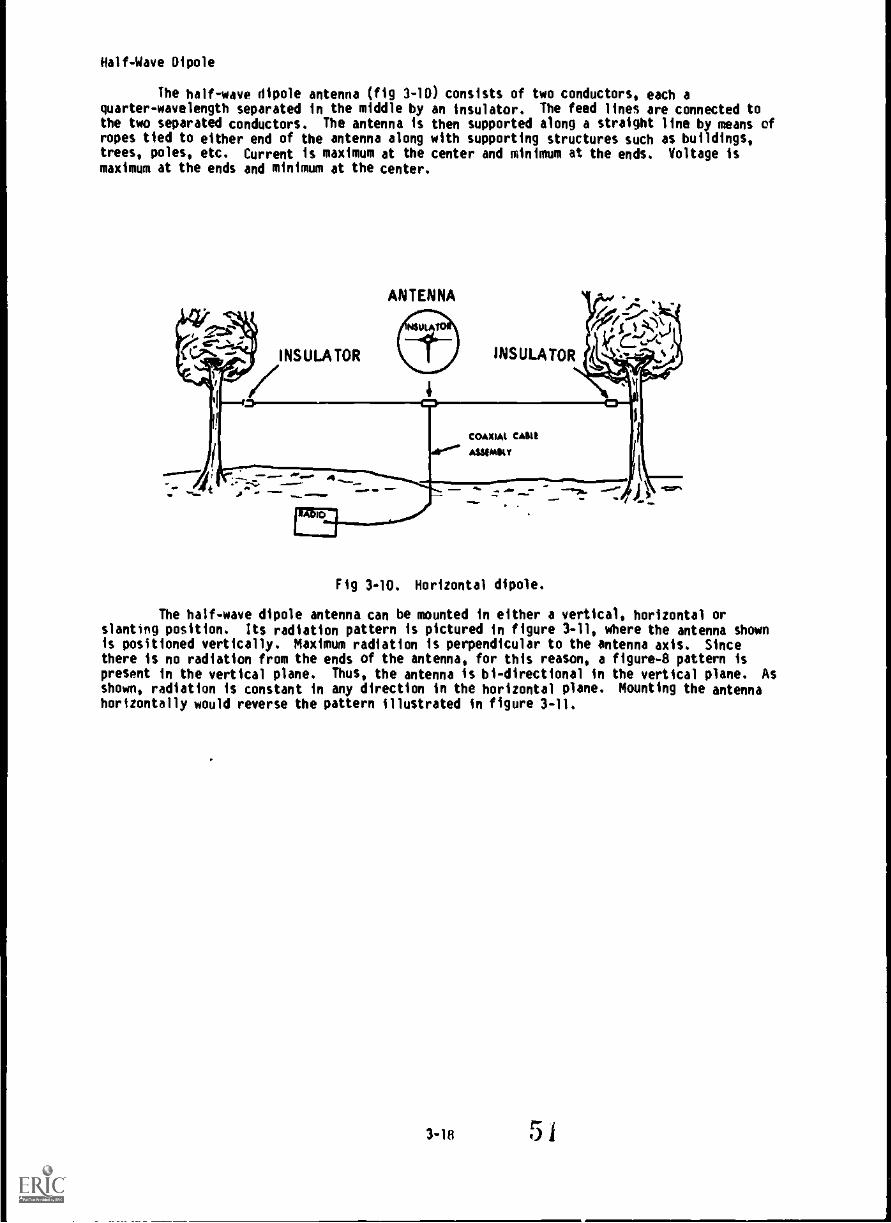
Half-Wave Dipole
The half-wave dipole antenna (fig 3-10 consists of two conductors, each aquarter-wavelength separated in the middle by an insulator. The feed lines are connected tothe two separated conductors. The antenna is then supported along a straight line by means ofropes tied to either end of the antenna along with supporting structures such as buildings,trees, poles, etc. Current is maximum at the center and minimum at the ends. Voltage ismaximum at the ends and minimum at the center.
ANTENNA
INSULATOR 1 INSULATOR
OW,. 4....U........... Z.V.=j ...:.....d... .0...... ...11P '''.
COAXM4 CAM
Ar"' ASSIMUY
Fig 3-10. Horizontal dipole.
The half-wave dipole antenna can be mounted in either a vertical, horizontal orslanting position. Its radiation pattern is pictured in figure 3-11, where the antenna shownis positioned vertically. Maximum radiation is perpendicular to the antenna WS. Sincethere is no radiation from the ends of the antenna, for this reason, a figure-8 pattern ispresent in the vertical plane. Thus, the antenna is bi-directional in the vertical plane. Asshown, radiation is constant in any direction in the horizontal plane. Mounting the antennahorizontally would reverse the pattern illustrated in figure 3-11.

ANTENNAAXS
HORIZONTALPLANE
PATTERN
VERTICALPLANE
PATTERN
MO*
SOLID PATr RN
Fig 3-11. Radiation pattern of a dipole (half-wave) antenna.
Formula for actual construction is shown in appendix I.
Two-Element Yagi
This configuration may be new to most communicators. As seen in figure 3-12, itconsists of a reflecting element (a single wire) mounted 1/4-wavelength behind a dipoleantenna. This addition will substantially increase the gain and make the antenna moredirectional.
Fig 3-12. Two-element yogi.
Construction for the two element yagi is shown in appendix I.
Long Wire Antenna
Long wire antennas (fig 3-13) are long single wires supended 1/2-wavelength above theground and consist of an order of 2-6 wavelengths long. Long wire antennas have two basicadvantages over other antennas. These advantages are increased gain and directivity.
3-19
52
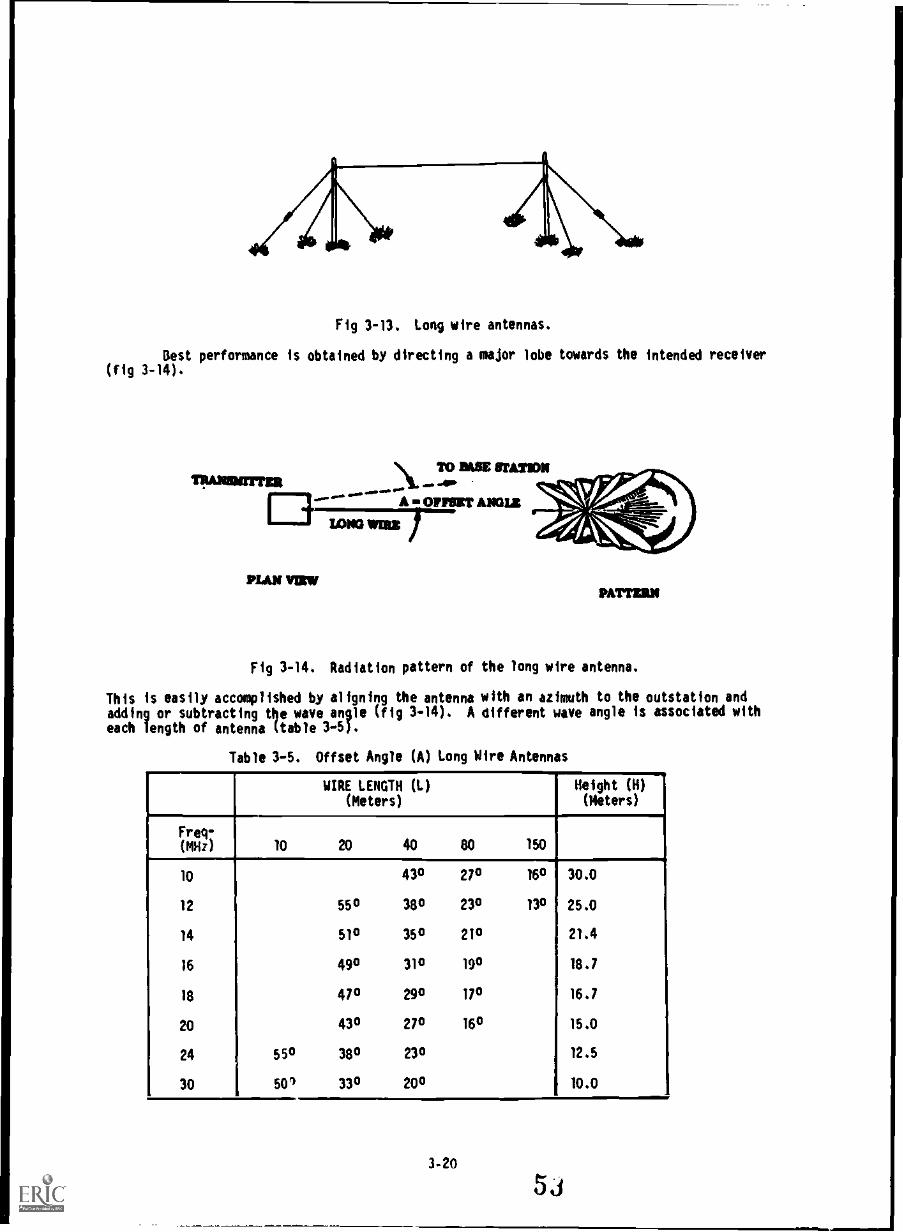
4/1.\4 g<\Nrig 3-13. Long wire antennas.
Best performance is obtained by directing a major lobe towards the intended receiver(fig 3-14).
PLAN V1RWPATTI=
rig 3-14. Radiation pattern of the long wire antenna.
This is easily accomplished by aligning the antenna with an azimuth to the outstation and
adding or subtracting the wave angle (fig 3-14). A different wave angle is associated with
each length of antenna (table 3-5).
Table 3-5. Offset Angle (A) Long Wire Antennas
WIRE LENGTH (L)(Meters)
Height (H)(Meters)
.
Frei-
.
(MHz).
10 20 40 80 150'4
10 430 270 160 30.0
12 550 380 230 13° 25.0
14 510 350 210 21.4
16 490 310 190 18.7
18 470 290 170 16.7
20 430 270 160 15.0
24 550 380 230 12.5
30 1 SOD 330 200 10.0
3-20

Because of its high gain and the low elevation angle of its main radiation lobe, thelong horizontal wire antenna is one of the simplest antennas to erect.
The long wire antenna is capable of spanning distances in excess of 100 km and is oneof the most practical antennas for use against jamming. The long wire antenna isbi-directional to unidirectional construction of the long wire antenna is shown in appendix I.
Half-rhombic Antenna
The half-rhombic antenna (fig 3-4) is a terminated vertical antenna which resembles aobtuse-angle V antenna. With the half-rhombic antenna, an unbalanced transmission line and aground or counterpoise is used. As a result, a vertically polarized radio wave is producedand the antenna is bi-directional. The antenna can be made to be uni-directional byconnecting a resistor of about 500 ohms between the far end of the antenna and the ground.
Fig 3-15. Half-rhombic antenna.
The typical military half-rhombic ar.enna consists of a 100 -foot antenna wire erectedover a single 30-foot wooden mast ae an 85 -foot counterpoise wire placed under the antennaabout one foot off the ground and attached to both ends of the antenna. See appendix I forconstruction.
Sloping V Antenna
The sloping V antenna (fig 3-16) consists of downward sloping long wires arranged toform a "V' and is fed with current of opposite polarity. Moor lobes from each wire combinein such a way that maximum radiation occurs in the direction of a lobe that bisects the angleof the legs. The pattern is basically bi-directional along the lines bisecting the angle,producing primarily shy waves.
The greater the leg length, the greater effect of gain and directivity of theantenna. The gain (increase in effective power or performance) of a "V" antenna is almostdouble that of a single long wire, since the radiation from the lobes of two waves (legs)combine.
For maximum use of a "V" antenna, the legs should be cut to three wave lengths at thecenter frequency of the desired band with an apex angle of 55 degrees. The antenna can bemade more directional by terminating the individual legs with a non-inductive resistor ofabout 500 ohms. See appendix I for construction.
3-21 54

Fig 3-16. Sloping "V" antenna.
Vertical I/4-wave whip antenna
The vertical whip antenna is the most widely used omni-directional antenna found inthe military. The tactical communicator is most familiar with the whip antenna used onvehicles, and the ground plane antenna which is usually mounted on masts or other structures.
The expedient vertical 1/4-wave whip antenna (fig 3-17) is a single bare or insulatedwire held vertically by a means of support and connected to the antenna connector on the faceof the radio. The vertical whip is omni-(all) directional, and its efficiency is related tothe transmitting frequency and antenna height. At lower frequency, its efficiency is verylow, but as the frequency increases its efficiency also increases. Antenna height can behelped by placing the antenna on top of a hill or by fastening it to a pole or tree toincrease its height above surrounding terrain o structures.
:);) 5

Fig 3-17. Vertical 1/4-wave whip antenna.
See appendix I for construction examples.
Field Expedient Ground Plane Antennas
Field expedient versions of the issue RC-292 operates at frequencies above 20 MHz.They are either pole supported or tree hung (fig 3-18). their radiation pattern isomnidirectional. the vertical and ground plane elements are cut for a 1/4-wave, the groundplane elements should be at 45-degree angles. Insulators are used to separate verticalelements from the ground plane elements.
3-23
56

Fig 3.18. Field expedient ground plane antennas.
See appendix I for construction example.
3-24
5 ji

EXERCISE: Answer the following questions and check your responses against those listed atthe end of this study unit.
Matchin : from the following illustrations (a through g), match the various fieldex ent antennas. Place the correct letter of the illustration in the spacesprovided.
Column 1 Column 2
field expedient antennas Illustrations
1. Half-wave dipole---2. Lone Wire
3. Sloping V4. Vertical 1/4 -wave whip5. Two-element yagi6. Half rhombic
Ground plane
a.
b.

f
9.
8. How can the long wire antenna best performance be obtained?
9. What happens to a half-rhombic antenna terminated in a resistor?
10. What length should the vertical and ground plane elements for an expedient ground
plane antenna be cut?
Work Unit 3-5. TRANSMISSION LINES
DEFINE TRANSMISSION LINE.
OESCRIBE STANDING WAVES.
GIVEN THE TYPES OF TRANSMISSIONS, MATCH EACH TRANSMISSION WITH THE APPROPRIATEILLUSTRATION.
STATE THE AOVANTAGES IN USING A TWISTED PAIR TRANSMISSION LINE.
STATE ONE DISADVANTAGE IN USING A TWISTED PAIR TRANSMISSION LINE.
STATE ONE ADVANTAGE Ili USING A SHIELDED PAIR TRANSMISSION LINE.
3-26

Transmission Lines
A transmission line is a conductor that transfers radio frequency (RF) energy from thetransmitter to the antenna or from the antenna to the receiver.
Transmission lines fall into two main categories: balanced and unbalanced lines. Theterms balanced and unbalanced describe the relationship between transmission line conductors'id the earth. The balanced line is composed of two identical conductors, usually circularwires, separated by air or an insulating material. The voltage between each conductor andground, produced by an RF wave as it moves down a balanced line, are equal and opposite; i.e.,at the moment one of the conductors supports a positive voltage with respect to ground, theother supports a negative voltage of equal magnitude. Some balanced transmission lines carrya third conductor; sometimes in the form of a braided shield which acts as a ground.Unbalanced lines are usually seen in the form of an open single wire line or coaxial cable.The unbalanced line can be imagined as just one half of a balanced line. Example of balancedand unbalanced lines are shown in figure 3-19.
Standing Waves
A standing wave is a motionless wave on an antenna accomplished by an impedancemismatch. When an impedance mismatch occurs in an antenna system, voltage and current isreflected back down the transmission line to the transmitter. This causes a power loss andresults in poor antenna effic:ency.
Circuits that contain cappcttance or inductance and operate at some frequency haveimpedance (impedance describes the nature and size of whatever impedes the flow of current andwave). Impedance like resistance uses ohms as its unit of measure but cannot be measured withan ordinary ohmmeter.
The impedance of an antenna at the point where the lead-in (called a feed line ortransmission line) is attached is called the antenna input impedance. For maximum efficiency,an antenna must be the proper length for the frequency at which it operates. Just asimportant, the characteristic impedance or impedance of the transmission line and the antennainput impedance must match. If a mismatch occurs anywhere to the antenna system, standingwaves will result. Equally important as the impedance of the feed line matching the antenna,the output impedance of the transmitter must also match the impedance of the feedline.
Most military transmitters provide 50-ohm impedance at the antenna output. Mostexpedient half-wave antennas have approximately 70-ohm impedance. By matching thetransmission line to the transmitter with a 50-ohm line, we have a 20-ohm difference at theantenna, or by matching the transmission line to the antenna with a 70-ohm line we would havea 20-ohm difference at the transmitter. The mismatch at the transmitter end or the antennaend, produces what we refer to as a standing wave ratio (SWR). With a 70-ohm to 50-ohmration, we find that we have a 1.4 to 1 SWR (this is found by dividing 70.0 ohms by 50 ohms).With our HF equipment, it is recommended that you no NOT operate a system with a mismatch, orSWR greater than 1.5 to 1.
Types of transmission lines
(1) Parallel two-wire line. The parallel two-wire line (fig 3-20) consists of twopatainrariorl--ictorsseparated by insulators or spreaders at various intervals. It
is available in two types: spreader bar and twin lead. The spreader bar type usesceramic or polystyrene bars as spacers between the two conductors. The impedancefor this type of line is from 50-700 ohms. The twin lead consists of twoconductors that are molded into a low-loss polyethylene plastic. Its availablein impedances ranging from 75 to 300 ohms.
(2) Twisted air. The twisted pair transmission line (fig 3-20) consists of twonsu a e conductors twisted together. Two features of the twisting are: holdingthe line together and cancelling out the effects of nearby magnetic/electricfields. The impedance is generally 70 to 100 ohms. The advantages to this typeof line are ease of construction and readily accessible material. Thedisadvantages of the twisted pair transmission lines are: some RF loss intransmission line power, extreme care must be taken when using this type oftransmission se with of HF or high powered equipment in order to prevent shockhazard and ' ensure that the wire used is capable of handling the transmitterpower, and the impedance difference between the transmitter and the line at 20 to50 ohms.
3-27
6
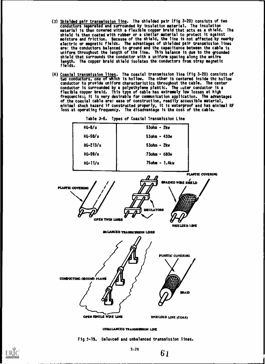
(3) Shielded pair transmission line. The shielded pair (fig 3-20) consists of two
conductors separated and surrounded by insulation material. The insulationmaterial is then covered with a flexible copper braid that acts as a shield. Theshield is then coated with rubber or a similar material to protect it againstmoisture and friction. Because of the shield, the line is not affected by nearby
electric or magnetic fields. The advantages of shielded pair transmission linesare: the conductors balanced to ground and the capacitance between the cable isuniform throughout the length of the line. This balance is due to the groundedshield that surrounds the conductor with a uniform spacing along the entire
length. The copper braid shield isolates the conductors from stray magneticfields.
(4) Coaxial transmission lines. The coaxial transmission line (fig 3-20) consists oftwo conductors, one of which is hollow. The other is centered inside the hollowconductor to provide uniform characteristics throughout the cable. The centerconductor is surrounded by a polyethylene plastic. The voter conductor is aflexible copper braid. This type of cable has extremely low losses at highfreqcencle:; it is very desirable for communication application. The advantagesof the coaxial cable are: ease of construction, readily accessible material,minimal shock hazard if constructed properly, it is waterproof and has minimal RFloss at operating frequency. The disadvantage is the cost of the cable.
Table 3-6. Types of Coaxial Transmission Line
RG-8/u
RG -58/u
RG -213/u
RG -59/u
RG -11/u
OPEN MN was
S3ohm - 2kw
S3ohm - 430w
S3ohm - 2kw
73ohm - 680w
75ohm 1.4kw
MIASICIE TRANINZINIONLDIES
maELDED LINE
PLASTIC COVERING
OREN MINNA WIRE LINE MELDED use (COMO
MGM IAMBI) TRANINIISSIoN LINE
Fig 3-19. Balanced and unbalanced transmission lines.
3-28
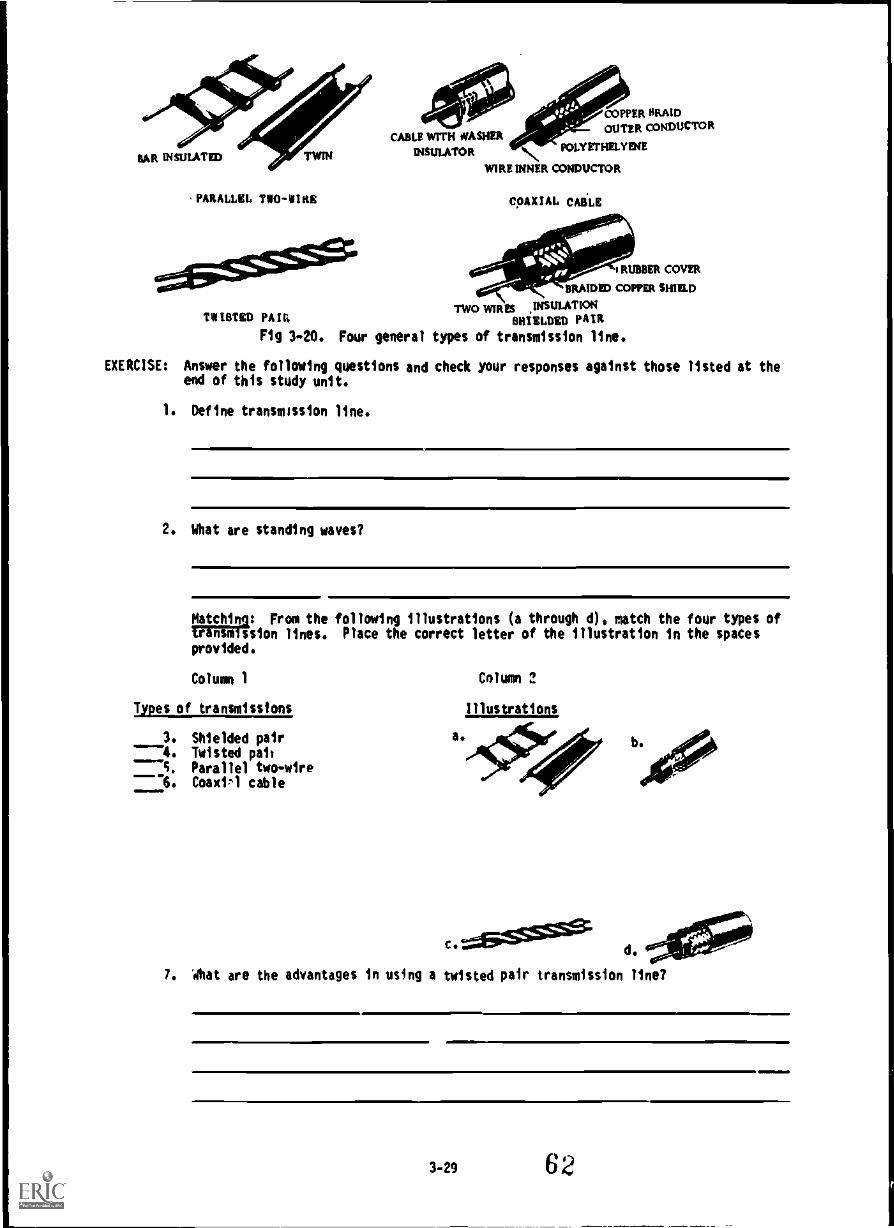
.PARALLEL TWO-WIR8
'MISTED PA II
Fig 3-20.
EXERCISE: Answer the followingend of this study uni
COPPER SRAMOUTER CONDUCTOR
CABLE IVITH WASHERUT
INSULATOR POLYETHELYITIE
WIRE INNER CONDUCTOR
Four general
questions andt.
1. Define transmission line.
COAXIAL. CABLE
* 4114,RUBBER COVER
.4? BRAIDED COPPER SHIELD
Mown INSULATIONSHIELDED PAIR
types of transmission line.
check your responses against those listed at the
2. What are standing waves?
Natchin : From the following illustrations (a through d), match the four types oftransmission lines. Place the correct letter of the illustration in the spacesprovided.
Column 1
Types of transmissions
3. Shielded pair----4. Twisted pal,---5. Parallel two-wire6. Coaxil cable
a.
c.
Column 2
Illustrations
d.
7. Ahat are the advantages in using a twisted pair transmission line?
3-29 62

8. One disadvantage in using a twisted pair transmission line is
9. One advantage in using a shielded pair transmission line is
SUMMARY REVIEW
In this study unit, you have learned about the functions of an antenna. You havelearned about antenna polarization, the polarization requirements of various frequencies andabout the conventional field antennas used within the Marine Corps. You have also learnedseveral types of field expedient antennas and several types of transmission lines that can beused to feed these antennas.
Answers to Study Unit #3 Exercises
Work Unit 3-1.
1. To convert the output power delivered by a radio transmitter into anelectromagnetic field that is radiated through space
7. To convert the electromagnetic field that sweeps by it into energy that isdelivered to a radio receiver
3. Radiation field4. electric, magnetic5. electromagnetic
Work Unit 3-2,
1. By the direction of the lines of force making up the electric field1. a. Vertical
b. liorizontal
3. Vertical
4. They can be vade to radiate effectively at high angles and have inherentdirectional properties
5. Vertical or horizontal6. b
7. a
R. a
9. b
Work Unit 3-3.
1. An elevated, wide band, modified ground plane antenna1. A man-transportable tactical log periodic antenna3. AS-2236/ORC4. AS-2259/GR
Work Unit 3-4.
1. d
9. a
3. b4. r
5. e
7. 9
R. fly directing a major lobe towards the intended receiver9. its becomes uni-directional10. One quarter (1/4) wave
3-30

Work Unit 3-5.
1. A conductor that transfers radio frequency (RF) energy from the transmitter to theantenna or from the antenna to the receiver
2. A motionless wave on an antennaJ. d4. b
5. a
6. c
7. Ease of construction and readily accessible material8. some RF loss in transmission line power, or care must be taken when using this
type of line with hF or high powered equipment9. the conductor balanced to ground
3-31

wur JNI1 4
(CACIION AND !MINNA GROUNDING
STUDY UNIT OBJECIIVE: WIIHOUT THE AID OF REFERENCES, YOU WILL IDENTIFY THETECHNICAL AND TACTICAL REQUIREMENTS OF SITE SELECTION. YOU WILL ALSO IDENTIFYVARIOUS ELECTRONIC COUNTER - COUNTERMEASURES PRECAUTIONS THAT CAN BE TAKEN WHENSELECTING AN ANTFNNA SITE. LASTLY, YOU WILL IDENTIFY VARIOUS TYPES OF GROUNDINGDEVICES.
Two factors play an important role in equipment siting: optimum communications andcamouflage. Unfortunately, it is seldom possible to locate your equipment, in order tocommunicate well and yet be hidden from enemy view, fire, or direction finding.
From a communications point of vi-w, the Ideal location for a radio antenna is as far awayfrom cover as possible such as a bar mountaintop or out in the middle of a large field.Obviously, this does not agree with the commander's requirement to be hidden from view as muchas possible; therefore, planning the location of equipment must be detailed to achieve thebest results. Because you can not always obtain the best locations for your antenna sites,antenna grounding is also an important factor to consider. Probably the most frequent causeof a weak s.gnal, especially lIF signals, is poor grounding. You can easily cut yourcommunication distance in half by not grounding the antenna. Another important factor toremember about ungrounded high powered transmitters is getting shocked, badly burned, orkilled.
Work Unit 4-1. REQUIREMEH1S FOR SITE SELECTION
GIVEN A LIST OF SEVERAL FACTORS FOR ANTENNA SITE SELECTION AND A LIST OF THE TYPESOF CATEGORIES THESE FACTORS FALL UNDER, MATCH THE FACTOR WITH THE APPROPRIATECATEGORY.
The choice of an antenna site will depend on the nature of the local interveningterrain and the tactical sit,ation. Planning should always be preceded by a careful study cctterrain maps and whenever possible, by reconnaissance in order to obtain detailed informationconcerning the availability. accessibility, and size of desirable sites.
Technical Factors. Factors to be considered will depend on the type of equipment used andthe tactIcirsituatTon.
a. Location. A radio station must be located in a position that will ensurecommunicatiorME-ill other stations with which it is to operate. To obtain efficienttransmission and reception, the following factors should be considered:
(1) Hills and mountains between stations normally limit the range of radio sets.In mountainous or hilly terrain, positions relatively high on the slopes (fig4-1) should be selected. Locations at the base of a cliff or in a deep ravineor valley should be avoided. For operation at frequencies abave 30 MHz, alocation that will give line-of-sight communication should be selectedwhenever possible.
(2) Dry ground has resistance and limits the range of the radio set. If possible,the station should be located near moist ground, which has much lessresistance. Water, and in particular salt water, will greatly increase thedistances that can be covered.
(3) Trees with heavy foliage absorb radio waves, and leafy trees have a moreadverse effect than evergreens. The antenna should be kept clear of allfoliage and dense brush.
b. Nan-made obstructions
(1) A position in a tunnel or beneath an underpass or steel bridge (fig 41)should not be selected. lransmission and reception under these conditions arealmost Wossible because of high absorption of KF waves.

(2) Buildings located between radio stations, particularly steel and reinforcedconcrete structures, hinder transmission and reception.
(3) All types of pole wire lines, such as telephone, telegraph, and high-tensionpower lines, should be avoided in selecting a site for a radio station. Suchwire lines absorb power from radiating antennas located in their vicinity.They also introduce hum and noise interference in receiving antennas.
(4) Positions adjacent to heavily traveled roads and 4ighways should be avoided.In addition to the noise and confusion caused by tanks and trucks, ignitionsystems in these vehicles may cause electrical interference.
(6) Battery-charging units and generators should not be located close to the radiostation.
(6) Radio stations should not be located close to each other.
(7) Radio stations should be located in relatively quiet areas. Copying weaksignals requires great concentration by the operator, and his attention shouldnot be diverted by extraneous noises.
T//ESE PLACES ARE beAD FOR RAP/0
Fiq 4.1. Antenna siting.

Tactical Factors
4. lace) command requirements. Radio stations should be located some distance fromthe unit head4uaite or command 1:that they serve. Thus, long-range enemy artillery fire,missiles, or aerial bombardment, directed at the stations as a result of enemy directionfinding, will net strike the command post area.
b. Cover and concealment. The locations selected should provide the best cover andconcealment Possible, consistent with good transmission and reception. Perfect cover andconcealment may impair transmission and reception. The amount of permissible impairmentdepends on the range required, the power of the transmitter, the sensitivity of the receiver,the efficiency of the antenna system, and the nature of the terrain. When a set is being usedto communicate over a distance that is well under the maximum range, some sacrifice ofcommunication efficiency can be made to permit better concealment of the set from enemyobservation.
Practical Considerations
a. Pack sets have sufficiently long cordage to permit operation from cover, while theradio set is below the surface of the surrounding terrain and the antenna is in the clear.
h. Some sets can he controlled remotely from distances of 100 feet or more. Sets ofthis type can be set up in a relatively exposed position, while the operator remains concealed.
c. Antennas cf all radio sets must extend above the surface of the ground to permitnormal communications.
d. Small tactical set antennas are usually of the whip type. These antennas aredifficult to see from a distance, especially if they are not silhouetted against the sky.
e. Open crests of hills and mountains must be avoided. A slightly defiladed positionjust behind the crest gives better concealment and sometimes provides better transmission.
f. All permanent and semipermanent positions shnuld be properly camouflaged forProtection against both aerial and ground observation. However, the antenna should not touchtrees, brush, or camouflage material.
Local communications. Contact must be maintained between the radio set and the messagecenter at all 'imes, either by local messenger or field telephone. The station should also bereadily accessible to the unit commander and his staff.
Final considerations. It is almost impossible to select a radio site that will satisfyall technical and tactical requirements . Therefore, a cumpromise is usually necessary, andthe best site available is selected. It is also a good idea to select both a primary and analternate site. Then, if radio communication cannot be established at the primary location,the set can be moved a short distance to the alternate position.
EXERCISE: Answer the following questions and check your responses against those listed atthe end of this study unit.
Matching: Column 1 (items 1-5) lists several factors for antenna site selection.Column 2 (a and b) lists the types of categories these factors fall under (eithertechnical or tactical). Match the factor in column 1 with its specific categoryin column 2. Write your answers in the spaces provided.
Cnlumn 1
Factors
1. Local command requirements7. Location3. Men-made obstructions4. Cover and cnncealment5. Practical considerations
Column 2
Type of Category
a. Technicalh. Tactical
4-36/

Work Unit 4-2. ELECTRONIC WARFARE ANTENNA SITING
DEFINE ANTENNA MASKING.
NAME ONE ADVANTAGE OF USING DIRECHONAL HOR:ZONTALLY POLARILEO ANTENNAS IN AN EWENVIRONMENT.
Antenna Marking
Antenna masking (fig 4-2) is the technique of hiding radio signals behind terrain. It
is an inexpensive way to confuse RDF efforts. VHF radio waves bend; they are flected bybuildings and mountains, and absorbed by trees. When this happens, it is difficult todetermine the original direction from which the wave was transmitted, but the ability to hearthe signal is minimally affected. A radio operator can advantageously use this principle byattempting to place terrain obstacles between the transmitter and the FEBA, while affording anunblocked path to the intended receivers. Hills, lakes, and dense forest also provide terrainohstacles. Antenna masking also occurs when antennas are positioned on the back slopes ofhills. A radio operator should also erect antennas as low as adequate communications permit,and, in all cases, antennas should be camouflage, to blend with terrain.
ei-.4,rivi.? ..44., ahem .
-7";`' 7
f:q.. I40....nrj. 11,ttp
i .. 1. 7I. ..lr: ''.._ Iv: ..
%.' .1 Nir A. .4. 6
.
. ,...,
, 'I.
v.:'.:.t.4* .- I. #.........7 -, /
..t.10 cl lain I ,mu too ( oto whew
'. ., .......aW....P ... 44
'r 4.1.:-/
.rIP 'I i- N.--...,,, .C LI' I ...r. ilk". -..44 e.:
,fil4.1,:n. AI,-.it - ,0).-.-...:- 4dye. 'S.. ... .e.g -,..... ..8.
.A.I.o.. ..0.0.9. ..P. I'4:4Z--.411.',
.. t.i . '
A . N.
.
*...
a e
4:.Ni
./ &sou, a .. lko 4 ste101 01 Of
".; 4. ' rt 1.." ..., ;-1it.
4 mos o oat. se 010*Ilt SOVit /"..iigifr.I' ..'r
rs'
Fig 4-2. Antenna masking.
Antenna dispersion
Antennas must be dispersed so that all of the radiations are not coming from onecentral antenna form. Terrain analysis can show us antenna locations which provide naturalmasking from the enemy. We need to plan for as many alternate locations as possible. Thisterrain analysis can be aided with the use of the services of the Electro-magneticCompatibility Analysis Center (ECAC) see appendix II.
Use Directional Horizontally Polarized Antennas
For versatility, the omni - directional vtically polarized antenna is best. The
flexibility provided by omni-direction41 antenna*. is important to the commander during theattack, when it is difficult to maintain Corrmt orientation for horizontally polarized
4 A

directional antenras. Vertically polarized omni-directional antennas are required for
communications between moving vehicles. However, when ECCM is considered, the
omni-directional antenna has one chief disadvantage--danger. Omni-directional antenna signals
travel 411 a 360-degree radius and usually well across the FEBA where they are susceptible to
interception and ROF. Horizontally polarized directional antennas should be considered for
lateral communications whenever possible.
Enemy forces primarily use Adcock and vertical loop RDF antennas which are designed foroptimum performance when receiving vertically polarized radio waves. A horizontally polarizedtransmitting VHF antenna will radiate a predominantly horizontally polarized wave from ten to
forty kilometers from the transmitter. The horizontally polarized wave will create somebearing error in an Adcock antenna, and a very large error in a vertical loop antenna. This
may cause an error 45 much five times greater than the usual operational error (about 20ees), creating unusable RDF bearings. It is impossible for an RDF operator to continually
,ujust tactical ground-operated RDF equipment, particularly Adcock antennas, to compensate forboth vertical and horizontal waves. If US forces would use both vertically and horizontallypolarized omni-directional and directional VHF antennas along with good COMSEC practices,direction findirq would become more difficult and expensive for our adversaries.
End- or center-fed half -wave or quarter -wave directional antennas offer many advantageswith VHF radios. For example, a doublet antenna provides a more Orectional signal antennawhich can reduce the enemy's ability to intercept the signal by 20 to 40 percent. It alsoprovides a 20 percent greater range, especially in wooded areas, by increasing ERP in thedesired direction. This is a useful ECCM technique.
The five advantages of
environment are:
(a) The horizontalInterference (jamming).
woods.
using directional horizontal polarization antennas in an EW
antenna produces a more stable signal in the presence of
(b) The horizontal antenna produces a more stable signal when used in or near dense
(c) The horizontal antenna is more readily camouflaged without loss of signal. Smallchanges in antenna location do not cause large variations in signal strength.
(d) Small changes in antenna location do not cause large variations in signal strength.
(e) The horizontal antenna is more difficult to direction find because of polarizationand because its signal can be directed to intended recipients and away from enemy RDF in manyapplications.
EXERCISE: Answer the following questionS and check your responses against those listed atthe end of this study unit.
l. Define antenna masking.
...
2. Name one advantage of using horizontal polarization in an EW environment.
Ark Unit GROUNDS AND COUNTERPOISES
DEFINE GROUNDING ROOS.
DEFINE RADIAL GROUNDS.
DEFINE COUNTERPOISE.
DESCRIBE A GROUND SCREEN.
Types of Grounds
When grounded antennas are used, it is especially important that the ground hare ashigh a conductivity as possible. This is neces,ary to reduce ground losses and to provide the: st possible reflecting surface for the down-going radiated energy from the antenna. Vace
low and medium frequencies the ground acts as a sufficiently good conductor. the problem is
4-5

how to make cunnection to the ground in such a way as to introduce the least possible amountof resistance in the ground connection. At higher frequencies, artificial grounds constructedof loge metal surfaces are common.
The ground connection takes many forms, depending on the type of instalhtion and theloss that can be tolerated. For fixed station installations, very elaborate ground systemsare used. These are frequently arranged over very large areas so that they operate as part ofthe reflecting surface in addition to making the connection to ground itself. In many simplefield installations, the ground connection is made by means of one or more metal rods driveninto the earth. Where more satisfactory arrangements cannot be maw, it may be possible tomake ground connections to existing devices which are themselves grounded. Metal structuresor underground pipe systems (such as, water pipes) commonly are used as ground connections. In
an emergency, a ground connection can be made by plunging one or more bayonets into the earth.
Sometimes, when an antenna must be erected over soil having a very low conductivity,it is advisable to treat the soil directly to reduce its resistance. Occasionally, the soilis mixed with a quantity of coal (lost for this purpose nr it can be treated with substanceswhich are highly conductive when in solution. Some of these substances, listed in order ofpreference, are sodium chloride (common salt), calcium chloride, copper sulphate (bluevitriol), magnesium sulphate (Epson salt), and the potassium nitrate (saltpeter). The amountrequired depends on the type of soil and its moisture content. When these substances areused, it is important that they do not get into nearby drinking water supplies.
Ornund Rods
With a less ,aborate pound system, a number of ground rods can be used. These rodsusually are made of galvanized iron, steel, or copperplated steel in lengths up to 8 feet.One end of the rod is pointed so that it can be driven easily into the earth. The other endfrequently is fitted with some type of clamp so that the ground lead can be attached. Someground rods are supplied with a length of ground lead already attached.
A fairly good ground connection can be made by using several ground rods, 6 to 10 feetapart, connected in parallel. If possible, the rods should be located in a moist section ofground or in a depression which will collect moisture. Ground resistance can be reducedconsiderably by treating the soil with any of the substances previously mentioned. A trenchabout a foot deep is dug around each ground rod and filled with some common rock salt, epsomsalt, or any of the other materials mentioned. The trench is then flooded with water, afterwhich it is covered with earth. To remain effective, this treatment should be renewed everyfew years.
For simple installations, a single ground rod can be fabricated in the field from pipeor conduit. It is important that a low resistance connection be made between the ground wireand the ground rod. The rod should be cleaned thoroughly by scraping and sandpapering at thepoint where the connection is to be made, and a clean ground clamp installed. A ground wirecan then be soldered or joined to the clamp. The joint should be covered with tape to preventan increase in resistance caused by oxidation.
wher field expedient ground rods are metal fence posts, steel reinforcing rods, waterpipes and metal building frame.
Radial Grounds
Radial grounds (fig 4-3) coisist of a number of bare conductors arranged radially andconnected. The -onductors, which may be from a tenth to a half-wave length or more, areburied a short distance beneath the surface of the earth. If possible, bare metal platesshould be attached to the wire ends which improves the quality of the ground.
4-5 70

....=
MIMED BARE WIRE /
Fig 4-3. Radial grounding.
L.:counter, rise
When an actual ground connection cannot be used because of the high resistance of thesoil or hecause a large buried ground system is not practicable, counterpoise may replace theusual direct ground connection in whicU current actually flows to and from the antenna throughthe ground itself. The counterpoise (fig 4-4) con-ists of a structure made of wire, which iserected a short distance off the ground and insulated from the ground. The size of thecounterpoise should he at least equal to or preferably larger than the size of the antenna.
When the antenna is mounted vertically, the counterpoise should be made ;rite a simplegeometric pattern such as those shown in figure 4-4. Perfect simietry is not required, butthe counterpoise should extend for equal distances in all directions from the antenna.
If some VHF antenna installations are on vehicles, the metal roof of the vehicle isused as a counterpoise for the antenna.
Small counterpoises of metal mesh are sometimes used with special VHF antennas thatmust he located a considerable distance above the ground. This counterpoise provides anartificial ground that helps to produce the required radiation pattern.
Fig 4-4. Counterpoise.
Ground Screen
A ground screen consists of a fairly large area of metal mesh or screen that is laidon the surface of the ground under the antenna. Its purpose is to simulate to some extent theeffect of a perfect conducting uround under the antenna.
4-1 71

There are two specific advantages that can be gained through use of a ground screen.First, the ground screen reduces ground absorption losses that occur when an antenna iserected uvur imperfectly conducting ground and second, the height of the antenna can be setaccurately. As a result of this, the radiation resistance of the antenna can be determined,and the radiation patterns of the antenna can be predicted more accurately.
EXERCISE: Answer the following questions and check your responses against those listed atthe end of this study unit.
1. What are grounding rods?
m-=11.m.
2. What are radial grounds?
3. What is counterpoise?
4. Describe a ground screen. 41IMII
SURMARY REVIEW
In this study unit, you have learned about the technical and tactical requirements of
antenna site selection. You have learned various ECCII precautions that can be taken whenselecting an antenna site. You have also learned about the various types of antenna grounds,which will help to improve communications.
Answers to Study Unit PI Exercises
Work Unit 4-1.
I. b
2. a
3. a4. b
5. b
Work Unit 4-2.
1. The technique of hiding radio signals behind terrain
2. (Any one of the following five is correct)
(1) The horizontal antenna produces a more stable signal in the presence ofinterference (jamming).
(2) The horizontal antenna produces a more stable signal when used in or neardense woods.
(3) The horizontal antenna is more readily camouflaged without loss of signal.(4) Small changes in antenna location do not cause large variations in signal
strength.
(5) The horizontal antenna is more difficult to direction find incause ofpolarization and because its signal can be directed to intended recipients andaway from enemy ROF in many applications.
Work Unit 4-3.
1. Galvanized iron, steel, or copper plated steel in lengths up to 8 feet with oneend of the rod po,nted and the other end clamped.
O-g 7i,4e

2. A number of bare conductors arranged readily connected and burled a short distancebeneath the surface of the earth.
3. A structure made of wire, which is executed a short distance offinsulated from the ground.
4. A ground screen consists of a fairly large area of metal mesh orlaid on the surface of the ground under the antenna.
the ground and
screen that is

ANTENNA CONSTRUCTION AND PROPOGATION OF RADIO WAVES
Review Lesson
Instructions: This review lesson is designed to aid you in preparing for your finalexamination. You 'hould try to complete this lesson without '.he aid of reference materials,but if you do not know an answer, look it up and remember what it is. The enclosed answersheet must be filled out according to the instructions on its reverse side and mailed to MCIusing the envelope provided. The questions you miss will be listed with references on afeedback sheet (MCI-R69), which Mill be mailed to your commanding officer with your finalexam. You should study the reference materials for the questions you missed before taking thefinal exam.
A. 'iultiple choice: Select tht ONE answer that BEST completes the statement or answers thequestion. After the corresponding number on the answer sheet, blacken the appropriatecircle.
Value: 1 point each
1. What part of a radio set is used for sending radio signals?
a. Demodulatorb. Transmitterc. Receiverd. Amplifier
2. What component of a radio set takes the electromagnetic waves and developes anelectrical signal, which amplifies and demodulates into an audible signal?
a. Antennab. Receiver
c. Transmitterd. Power converter
3. What device is used for radiating or receiving radio waves?
a. Receiverb. Transmitterc. Antennad. Demodulator
4. What provides operating voltage to a radio set?
a. Power supplyb. Direct currentc. Alternating currentd. Carrier wave
S. Electromagnetic energy radiated from an antenna is known as waves.
a. skyb. ground
c. magneticd. radio
6. The number of complete cycles that occurs in one second determines the
a. speed at which electromagnetic energy travels through space.b. frequency of a radio wave.c. amount of energy available in a power supply.d. type of power supply needed to operate a radio set.
7. What is the formula for finding the wavelength of an antenna when the frequency isknown?
a. 3000 c. 3000000
t. 300000300000 d. 300000000
R-1
7`t

8. What type of wave acts as a medium for the transmission of information signals?
4. Carrier
b. Frequencyc. Transmission
d. Received
9. The process which varies or modifies either the frequency or amplitude of the carrierwaveform is known as the
A. critical frequency.b. transmission.c. modulation.d. carrier wave converter.
10. Uhat type of modulation varies the power output of a transmitter?
e. FN
b. FSKc. SSBd. AN
11. What is the process called which varies the frequency of en unmoduleted carrier wavein proportion to the amplitude of the modulating signal?
a. FM c. ANb. FSK d. SSB
12. A gaseous mass which envelops the earth describes the
a. autnosphere. c. atmosphere.
b. source of ionization. d. regions in outer space.
13. The atmosphere is composed of three regions. Name them in order of their relativeheights.
a. Troposphere, ionosphere, and stratosphereb. Stratosphere, troposphere, and ionosphere
c. Troposhere, stratosphere and ionosphered. Ionosphere, troposphere, and stratosphere
14. A ground wave is a radio wave that travels
a. skyward.
b. skyward and near the earth's surface.
c. near the skip zon(.d. near the earth's surface.
15. The direct ground reflected and surface wave'. are all coiponents of thewave.
a. skyb. single hopc. troposphericd. ground
16. What type of radio wave depends on the ionosphere to provide signal paths betweentransmitter and receiver?
a. Skyb. Ground
c. Directd. Ground reflected

17. An area bounded by the outer edge of the usable ground wave propagation and the pointnearest the antenna at which the sky wave returns to earth is known as the
a. skip area.b. skip zone.c. unusable zone.d. skip distance.
19. Which region of the ionosphere has little effect in bending the paths of highfrequency radio waves?
a. 11
b. F2
c. E
d. D
19. During the day, all regions within the ionosphere are ionized. At night onlythe regions remain ionized.
a. D
b. E
c. F
d. G
20. The chief factor that controls long distance communication is theof the ionized layer.
a. expect -- locationb. ionization densityc. upper -- regiond. trapped -- waves
21. Which two layers of the ionosphere are the most highly ionized?
a. 0 and Eb. 0 and Fc. E and Fd. 0 and F-2
22. The highest frequency at which waves sent vertically upward are reflected directlyback to earth defines
a. the highest frequency of transmission.b. modes of transmission.c. critical frequency.d. interference frequency.
23. The frequencies that return to earth from a fixed angle of departure are known as theMUF. The MUF used in predicting the operating frequencies refers to the
a. maximum transmission distance possible for a given operating frequency.
b. minimum transmission distance possible for a given operating frequency.c. lowest frequency that wi.1 provide communication over a specified distance at a
given time.d. highest frequency that will provide communication over a specified distance at a
given time.
24. Waves of frequency that are transmitted above the will pass through theionosphere and escape into space.
a. MUFb. FOTc. LUFd. UHF

25. The lowest limiting frequency for satisfactory sky-wave communication for a radiocircuit at a particular time is known as the
a. LUF.b. LOF.c. LTF.
d. LHF.
25. The periodic increase and decrease of received radio strength is called
a. noise.b. reflection.c. fading,
d. interference.
?7. Ground-wave propagation is extremely useful for communication at
a. any frequency. c. high frequencies.b. low frequencies. d. superhigh frequencies.
2r.. What types of radio wave propagation are useful at the medium frequency band?
a, Sky onlyb. Sky and reflectedc. Around onlyd. Sky and ground
29. in the high frequency band what are the two types of wave propagation called?
a. Direct and sky c. Reflected and groundb. Reflected and direct d. Sky and ground
30. Which of the ground wave components listed below provides the best communicationspath when operating in the very-high-frequency band?
a. Ground reflected waveb. Surface wavec. Direct waved. Critical wave
31. The direct wave component of the ground wave is the only reliable propagation pathavailable when transmitting in the frequency band.
a. HF
b. ELFc. VLFd. UHF
32. A device which converts the output power delivered by a radio transmitter into anelectromagnetic field, that is radiated through space is the function of a
a. transmitting antenna. c. RF amplifier.b. power converter. d. AF amplifier.
33. What is the purpose of a receiving antenna?
a. To send received signals to the modulatorb. To vary the frequency of a radio wavec. To operate as a signal source for the receiverd. To radiate energy into space
34. if a transmitter is supplying power to an antenna, the fluctuating energy sets up twofields. Which of these two fields remain at a short distance from the antenna andbeyond?
a. Radiationb. Inductive
c. Magneticd. Electric
35. The radiation field is composed of two components. They are theelectric components.
a. induction c. electronb. magnetic d. oscillation
36. What field is formed from the electric and magnetic components of a radiated wave?
a. Electroinductive c. Magneticinductionb. Electromagnetic d. Electromotive
37. Polarization of a radiated wave is determined by the direction of the lines of forcemaking up the field.
a. magnetic c. electricb. induction d. radiation
38. There are two types of antenna polarization. !hat are these types of polarization?
a. Vertical and omni-directionalb. Vertical and horizontalc. Horizontal and directionald. Azimuthal and vertical
19. 4t low and medium frequencies, ground-wave transmission is used extensively. Whattype of polarization must be used?
a. Vertical c. Directionalb. Horizontal d. Azimuthal
40. Why is it better to horizontally polarize antennas at high frequencies?
a. They can be made to radiate effectively at high angles.b. They are omni-directional.c. %cause vertically radiated waves can not be refracted from the ionosphere.d. Because vertically polarized antennas have inherent directional properties.
41. At the very-high and ultra-high frequency bands, which type(s) of antennapolarization should be used?
a. Vertical polarization onlyb. Horizontal polarization onlyc. Neither vertical nor horizontald. Either vertical or horizontal polarization
42. The RC-292 is a(n) antenna.
a. center fed whipb. long wirec. fixed, mast mounted, to periodicd. elevated, wide band, modified ground plane
43. ',Mich antenna array assembly consist of a folding boom supporting a planar array ofseven log periodic dipole elements?
a. AS-1729b. AS-2236
c. AS-285I/TRd. AS-2259/GR
44. qhich antenna system consist of a collapsible folding log periodic shaped in theform of a square?
a. 4S -2236
b. AS-2950c. RC-290d. RC-292
45. A dipole antenna which consists of eight lightweight coaxial mast sections and fourradiating elements that also serve as guys is a(n) antenna.
As-892
b. AS-2851
c. AS-2236d. AS-7259
R-5

46. By aligning the antenna with an azimuth to the outstation and adding or subtractingthe wave angle, the major lobe of the antenna can be directed
toward the intended receiver.
a. half-wave dipoleb. long wirec. quarter-wave whipd. ground plane
47. What happens to a half-rhombic antenna, when terminated in a resistor?
a. It becomes uni-directional c. It becomes bi-directionalb. It becomes omnm-directional d. It becomes directional
48. When making a field expedient ground plane antenna, at what length should thevertical and ground plane elements be cut?
a. 1/4-wave c. 3/4-waveb. 1/2-wave d. 1-wave
49. A conductor that transfers radio frequency energy from the transmitter to the antennais called a line.
a. repeater c. transmissionb. carrier d. pulse
59. A standing wave is described as a
a. motionless wave on an antenna that is Caused by a perfect match.
b. motionless wave on an antenna that is caused by a mismatch.c. moving wave on an antenna that is caused by a perfect match.d. motionless wave on an antenna that causes a perfect match.
51. What are the advantages to using the twisted pair transmission line?
a. There is an RF energy loss in the line and readily accessible material
b. This type of line permits ease of construction and readily accessible materialc. It can be used with HF equipment without hazard and ease of constructiond. This type of line is balanced to ground and used with Hf equipment without hazard
52. One disadvantage of using the twisted pair transmission line is that
a. it's too difficult to work with.
b. it's balanced to ground.c. it's too expensive to use.d. care must be taken to ensure that the line is capable of handling the transmitter
power.
53. What is one advantage of using the shielded pair transmission line?
a. Ease of constructionb. Readily accessible material
c. Low cost of materiald. The conductors balanced to ground
54. The technique of hiding radio signals behifld terrain defines
a. decoy antennas. c. remote operation.
b. antenna dispersion. d. antenna masking.
55. What is one adqantage of using directional horizontally polarized antennas in an EW
environment?
a. The antenna is immune to jamming
b. The antenna can be used on vehicles while on the move
c. The antenna will transmit in a 3600 radiusd. A directional, horizontally polarized antenna is difficult for direction finding
equipment to find
R-67:1

56. Grounding devices made of galvanized iron or steel in lengths up to eight feet are
called
a. counterpoise. c. grounding rods.b. radial grounds. d. grounding screens.
57. What are radial grounds?
a. A structure made of wire which is erected a short distance above the ground.b. A large area of metal mesh or screen laid on the ground under an antenna.c. A large number of galvanized iron rods connected in parallel.d. A number of bare conductors arranged radially/and connected.
SS. What is a counterpoise?
a.
b.
c.
d.
A structure made of wire which is erected a shortinsulated from the ground.A large area of metal mesh or screen that is laidunder an antenna.A number of bare conductors arranged radially andA large number of galvanized metal rods connected
distance off the ground and
on the surface of the ground
connected.in a series.
69. What type of ground system consists of a fairly large area of metal mesh or screenthat is laid on the surface under an antenna?
a. Radial grounds c. Grounding rodsb. Ground screen d. Counterpoise
S. latching: Read the following directions carefully for each of the groups of items below.For each item select the one letter (a., b., c., or d.) indicating your choice. After thecorresponding number on the answer sheet, blacken the appropriate circle.
Value: 1 point each
GROUP I
In the group of items below (60-62) match the atmospheric layers in column 1, with thedescription in column 2.
Column 1
Atmospheric layer
60. Troposphere a.
61. Ionosphere b.
62. Stratosphere c.
Column 2
Description
The region of the atmosphere whichextends from the surface of the earth to aheight of about 6.8 milesThe region of the earth's atmospherecomposed of several distinct layersThe region of earth's atmosphere where thetemperature remains nearly constant
R7 3t

GROUP 2
In the group of items below (63-681, match the advantages of vertical and horizontalpolarization in column 1, with the types of antenna polarization in column 2.
Column 1 Column 2
Advantages of vertical andhortzonfaTipoTarization
63. Less affected by reflections fromaircraft flying over the transmissionpath
64. Picks up less interference from VHFand UHF broadcast transmission
65. Useful if it is desired to minizinginterference from certain directions
66. Useful when communicating with moving vehicles67. Suffers lower losses when located near
dense forests68. Less apt to pick up manmade interference
Types of antenna polarization
GROUP 3
a. Verticalb. Horizontal
In the groups of items below (69 -71) and (72-75) match the field expedient antennas incolumn 1, with the illustration in column 2.
Column 1
Field expedient antenna
69. HalfRhombic70. Long wire71. Half wave dipole
a.
Column 2
Illustration
04%tytt.

Column 1
Field expedient antenna
72. 1/4 wave whip73. sloping V74. Field expedient ground plane75. two element yag,
GROUP 4
a.
b.
c.
d.
GROUP 5
Column 2
Illustration
IT.
o'60
In the group of items below (76-80) match the factors for antenna sight selection incolumn 1, with the types of categories in column 20.
Column 1
Factors
76. Man-made obstructions77. Local command requ'rements78. Practical considerations79. Location80. Cover and concealment
Column 2
Types of category
a. Tactical
b. Technical
R-9
82
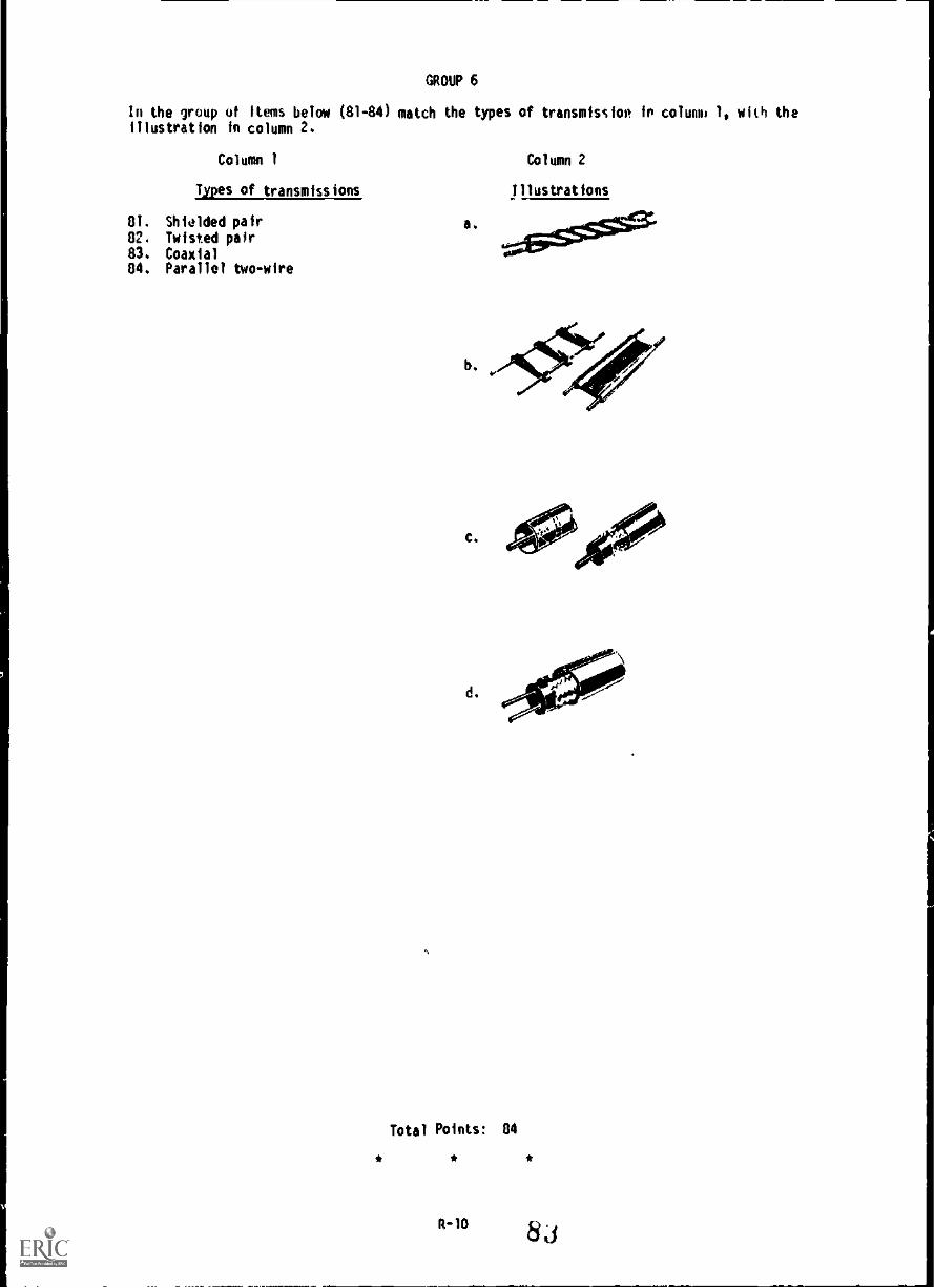
GROUP 6
In the group of items below (81-84) match the types of transmission in column, 1, with theillustration in column 2.
Column 1 Column 2
Types of transmissions Illustrations
81. Shiolded pair
82. Twisted pair83. Coaxial84. Parallel two-wire
a.
b 211$1:0/e
C.
d.
Total Points: 84
* * *
R-10 83

APPENDIX I
FIELD EXPEDIENT CONSTRUCT ION
This appendix discusses some field expedient solutions to repairing tactical whip andground plane antennas, if they become broken or damaged. This appendix also covers severefield expedient antennas which can be used along with conventional tactical antennas or inplace of these tactical antennas.
Iten you fabricate an antenna, there is one important fact that you oust keep in mind; thelocation of the station(s) you will need to communicate with. The direction and distance arecritical factors and the selection of the right type of antenna is important. easicall),there are three types of antennas accord ' to the directional characteristics, as shako infigure AI-1.
ONNI-Diroctional AUdireehomaRIDtrootioaal Any two opposite disooti000UNIDirectlosol Any out anodes
OMNIDIRECTIONAL
BI 0-The I)DIRECTIONAL
UNI THS I)DIRECTIONAL
.
Fig AI-1. ni recti anal characteristics.
Note: Appendix I is professional reference material desired to enhanceyour abilities ONLY; this information is not tested in this course.
AI-1
84

Omni-nirectioral Antennas
The vertical whip antenna is the most widely used omni-directional antenna found in themilitary. The tactical communicator is most familiar with the whip antenna used on vehicles,and the ground plane antenna which is usually mounted on masts or other structures.
The vertical whip is omoi-(oll) directional, and its efficiency is related to thetransmitting frequency and antenna height. At lower frequencies it efficiency is very low,but as the frequency is increased, its efficiency also increases. The problem with height canbe helped by placing the antenna on top of a hill or by fastening it to a pole or tree toincrease its height above surrounding structures.
If your whip antenna is damaged or missing, consider the following quick solutions to y.urproblem:
a. Metallic Whips. If a metallic whip antenna becomes broken into two pieces a splintis the quit.kesWou can make figure Al-2. The following steps are performed when
repairing this type of .rake:
(1) Scrape off the paint three to six inches from the broken ends.
(2) Obtain about one foot of copper wire or stripped UD-l.
(3) Overlay the cleared ends and wrap them together tightly wth the wire. If
possible, solder the connection.
(4) Place ;tick, pole, or branch on each side of the break and wrap thesplint tigntiy with WD-1, tape, rile or whatever is available.
If everything else is working right, you're ready to communicate.
8,)AI -2

STEP #1 STEP #3 STEP #4Fig AI -2. Metallic whip antenna (spliced).
AI -3
86

If your metallic whip antenna is broken and the top piece is lost, perform the followingsteps for a quick fix (fig AI-3):
Step 1. Obtain a pole 10 feet long, about 9 feet of WD-1, and some tape.
Step 2. Scrape off the paint from the top 2 inches of the whip's stub.
Step 3. Wrap 12 inches of bare wire around the scraped portion of the stub. Wrapvery tightly, pass it over the top of the stub, and jam it into the holewith a wooden peg and tape if possible.
Step 4. Tie the 10-foot pole tightly to the antenna base and stub.
Step S. Attach the WD-1 along the length of the pole with tape. Total length ofthe upright WOO and antenna stub should not be more than 9 feet.
Step 6. Trim away any extra wire.
You are now ready to communicate. Move slowly because this mast will not withstand abuselike the original, but will serve you well in an emergedcY.
STEP #2 STEP #3
STEP #1
fig AI-3. Metallic whip repair.
Al-4
sir
STEP #4,5

b. Fiberglass whips. If a fiberglass whip antenna breaks into two pieces, you cannotuse a splint to fix It like we did on metal whips. To repair a broken fiberglass whip followthese simple steps (fig AI-4):
(1) Obtain a 15-foot length of coaxial cable. Measure off 5 feet and strip therubber sleeve (cover) from the 5-foot section. Separate the braided shieldfrom the center conductor by
(a) Using a sharp knife, carefully cut through the outer insulation; do notcut into the braided shield. Once the insulation is cut evenly allaround, pull it off leaving the braided shield exposeo.
(b) Bend the coax in a loop and hold it in one hand. Using a nail or pencil,carefully separate the braided shield from the insulated centerconductor. Gradually work the pencil in between the coax and the centerconductor.
(c) Keeping the loop formed, stick a finger in the hole you made with thepencil ;old slowly pull the center conductor out of the braided shield.
(2) Obtain a 10-foot dry pole and lash it to the antenna base.
(3) Tape the center conductor to the top of the pole.
(4) Tape the braided shield to the bottom of the pole.
(5) Tape the stripped coax at several more places.
(6) If there's a INIC (twist lock type) connector on the coax, attach it to theradio. If not, wedge the center conductor firmly into the antenna connectorand attach the braided shield to a screwhead on the radio case. Remember,this is only a temporary solution, so replace it the first chance you get.
Al-5
88

STEP 1
STEP lb
STEP la
STEP lc
Fig AI-4. Fiberglass whip antenna repair.

STEP 2 STEP 3,4,5 STEP 6Fig A1-4. Fibergalss whip antenna repair -continued.
c. 1/4-wave vertical antennas. To replace regular 1/4-wave whip antennas execute thefollowing steps Tali: V41:
(1) Using the quick reference chart at the end of this appendix or the formula fora quarter wave, cut a piece of wire to the rcquired length.
(2) Attach an insulator to one end of the wire and attach the other end to theantenna connector on the radio.
(3) Tit another piece of wire or a piece of rope to the insulator end and throwthe wire/rope over a limb.
(4) Pull the antenna up until it is vertical and ready to go.
A1-7
90

234 4' frequency = Antenna length Infeet and Inches
STEP #1
STEP #2
fig Al-S. 1/4-wave vertical antennas.
STEP 3 STEP 4Fig A1-5. 1/4-wave vertical intennas--continued.
A1-8

The verticals (fig 41-6) are constructed the same way, but each has a different means ofsupport. They are all simple and quick to erect.
If you are using insulated wire, be sure to loop the wire around the handle of the radiobefore attaching it to the antenna connector. If your antenna is made of bare wire, use astake and insulator to keep the antenna %Are from pulling out the antenna connector on theradio.
Fig Al -6. 1/4-wave vertical antennas with a different means of support.
The illustrations shown in figure Al- 7 illustrates how to rig an antenna lead-in usingWD-1, which is a pair of twisted wires. Since a good electrical connection is a must, removean inch or two of insulation from the ends of the wires. Separate the three steel strandsfrom the four copper strands in each wire and cut the steel strands off at the insulation.Twist the four copper strands of each wire together. Connect the ends of the wires to theantenna and to the radio, and you have a usable antenna lead-in. For some antennas such asthe ground plane, the wire connected to the vertical element (inner part of a receptacle onthe antenna/ must connect to the inner part of the antenna receptacle or to an antennaterminal on the radio set. The other wire must connect to the outer shell of the antennareceptacles. Usually you can loosen one of the screws on the receptacle shells and connectthe wire at those points.
AT-9
92

COPPERSTRANDS
STEELSTRANDS
Fig A1-7. Rigging an antenna lead-in using WI.
d. RC-292 ground plane antenna. The RC-292 is a highly effective. omni-directionalantenna. It fs usually mueh more effective than a whip antenna. When thh antenna is damagedor not available, there are several versions that can be fabricated. To repair and/orfabricate the RC-292 antennas, here are some of the methods used:
(1) Mast and gig repair for RC-292. To repair an antenna with a broken mastsection and guylTne, follow these steps:
(a) Lay the broken mast end to end.
(b) Using a sturdy pole, splint the pieces of the mast together.
(c) Repair or replace the guy line, with rope or wire. If wire is used besure to use an insulator, this will prevent the wire from radiating.
STEP a
STEP bFig A1-8. Mast section and guyline repair RC-292.
Al-10

Fig AI-8. Mast section and guyline repair RC-292continued.
(2) Tree supported RC-292. This ground plane is a regular RC-292 antenna withoutmast sections or guy lines (fig AI-9). Follow these simple steps forinstallation:
(a) Attach an insulator to thr vertical element, and tie a piece of rope orwire to the other end of the insulator.
(b) Tie a weight on the other end of the rope, and throw the rope over a treelimb.
(c) Raise the antenna and tie off the rope.
AI-I1 94

STEP a
ST EP b STEP c
Fig AI -9. Tree support RC-292.
(3) Improvised (tree hung) RC-292. The tree hung (fig A1-10) can be a replacementfor the RC-292 in any emergency. This improvised antenna can be used inwooded areas where a tree limb can be used to raise the antenna. Follow thesesteps when making this type of improvised RC-292:
(a) Using the quick reference chart at the end of this appendix or the formulafor a 1/4-wave antenna, cut four wires for a 1/4-wave length each.
(b) Obtain three branches or slender sticks of wood.
(c) Position the three branches or sticks to form a triangle and tie the endstogeti er.
AI-12
ft,

(d) To each corner of the triangle, tie one end of each of the three 1/4-wavewires.
(e) Obtain an insulator and attach the other end's of the three wires to it.
(f) Attach the fourth 1/4-wave wire to the other end of the insulator.
(g) On the opposite end of the fourth 1/4wave wire attach another insulatorand to this insulator, attach a wire or rope which will be used to pullthe antenna up into the air.
(h) Attach an antenna lead-in to the antenna as shown in figure AI-10 beforeraising the antenna. One end of the lead in is attached to the 1/4-wavevertical element and the other end to the three ground plan elements.
(i) Lastly, raise antenna and tie it off. Then attach the antenna lead-in tothe antenna connector and radio chassis.
234 + operating frequency = quarter wave antenna
STEP a
STEP b
STEP drig AI-10. Improvised tree hung RC-292.
AI-13
96
1/4 wavelength each

STEP e
STEP f
STEP gFig AI-10. Improvised tree hung RC 292--continued.
AI-14
91,

....,...... To ground411----To antenna connector
STEP h STEP i
rig Al-10. Improvised tree hung RC-292--continued.
AI-I5
98

(4) Immvised gresundiplane (pole supported). This ground plane antenna (figAi -TI) can be used in areas where there are no trees to use as supports. It
can be constructed as follows:
STEP a
(a) Obtain a large pole.
(b) Compute and cut four wires for a quarter wave.
(c) Attach one quarter wave wire (vertical element) to the pole (the exactlocation of wire on the pole will depend on antenna length.
(d) Attach the other three 1/4 -wave wires (ground plane elements) to the
pole. Ensure that they are insulated from the vertical element.
(e) Attach insulators to each of the ground plane elements and attach anotherwire to the opposite end of each insulator.
(f) Raise pole and tie down the three ground plane elements.
(g) Connect an antenna lead in the vertical and ground plane elements and tothe antenna connector and radio ground.
STEP b
1
1/4 wavelength each.
STEP cFig AI-11. Improvised ground plane (pole supported) antenna.
AI-16

STEP d STEP e
STEP fog
Fig Al-11. Improvised ground plane (pole supported) antenna -- continued.
Al-17
100

Bi-directional and Uni-Directional A4tennas
a. One-half-wave Dipole. The Doublet or 1/2-wave dipole as it is more commonly called isa highly effective bi-directional antenna. It is normally used in the high frequency range,but can also be used effectively with radios that operate within the very-high-frequency range.
To construct the 1/2-wave dipole antenna, you will need the following items:
Two supports (trees or poles)
*Wire (both for the antenna and halyards). Rope can also be used for thehalyard.
Three insulators
To build this effective antenna follow these simple steps:
(1) Cut the wire to your operating frequency using the chart or formula to computethe length needed for a half-wave antenna.
(2) Determine your direction of transmission because this type of antenna isbi-directional.
(3) Cut the wire in half and put an insulator on each wire end and one in thecenter.
(4Y-fixate andtor erect tho two supports. Be certain they are 3 or 4 feet fartherapart than the antenna's actual length and broadside to the direction ofcommunications.
(5) Attach your antenna lead-in to both sides of the center insulator. Be surethat it is long enough to drop nearly to the ground and then to your radio'sposition.
(6) Tie ropes or wires to the two end insulators. Then, using whatever method is- easiest, hang the antenna up between the supports and keep it as taut as
possible.
(7) Connect one end of your antenna lead-in to the antenna connector and the otherto a ground point on or near the radio.
AI 11

STEP 1
STEP 2
STEP 3
Fig Al-12. 1/2-Wave dipole antenna construction.
AI-19 102

I
/0
co'
feI
%%.
OR
ANSTEP 4
Fig AI-12. 1/2-Wave dipole antenna construction--continued.
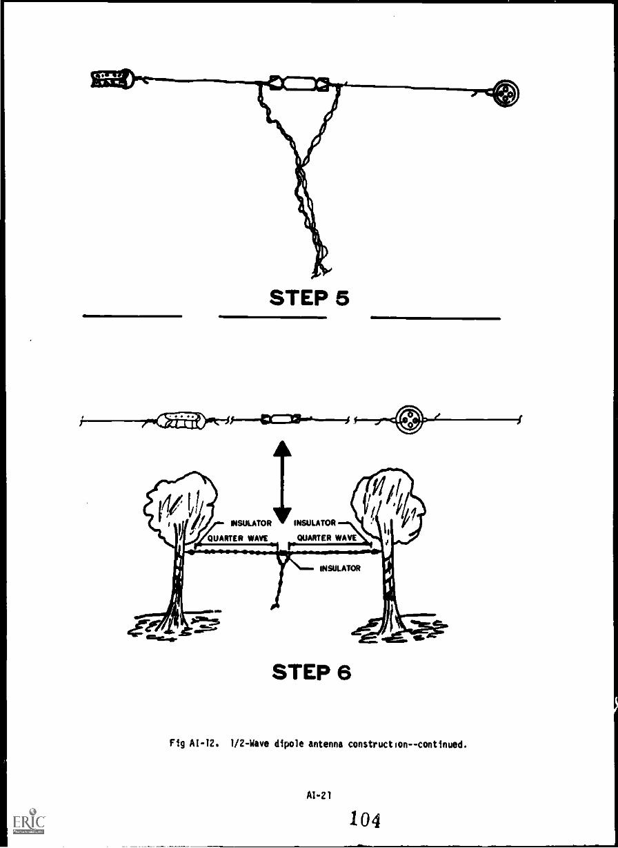
STEP 5
eirellOW114
INSULATOR V INSULATOR
QUARTER WAVE rQUARTER WAVE
INSULATOR
fgaIM.B.
STEP 6
Fig A1-12. 1/2-Wave dipole antenna construction--continued.
AI-21
104

INSULATOR INSULATOR
QUARTER WAVE OUARTMWAVEr--
INSULATOR
METAL STAB
Amer
STEP 7
Fig AL-12. 1/2-Wave dipole antenna constructioncontinued.

Fig AI-13. Improvised methods of supporting half-wave antennas.
b. Two-Element Ya i Antenna. This configuration may be new to some communicators. As
seen in gure - cons s s of a dipole modified by simply adding a reflecting element (asingle wire) 1/4 -wave length behind the dipole. This reflecting clement will help increasett,., gain and make the antenna more directional. To construct this antenna, simply add thereflecting element as follows:
(1) Construct a 1/2-wave dipole.
(2) Obtain two supports, either poles or trees.
(3) Cut reflecting element. Use 1.0468 divided by the operating frequency toobtain proper element length.
AI-23
106

(4) Attach the reflecting element to the supports and erect the reflecting element1/4-wave length behind the dipolk antenna. Ensure out - station is forward ofthe antenna and reflecting elements.
STEP 1Nit
AikSTEP 2
Fig At -14. Two-element yagi antenna.
A1-24 1 oy

468:operating frequency= element length
STEP 3
STEP 4
Fig A1-14. Two element yagi antennacontinued.
A1-25 108
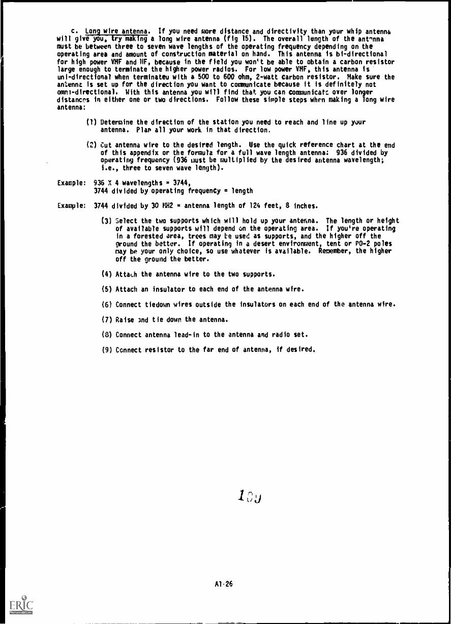
c. Long wire antenna. If you need more distance and directivity than your whip antennawill give you, fry making a long wire antenna (fig IS). The overall length of the antennamust be between three to seven wave lengths of the operating frequency depending on theoperating area and amount of construction material on hand. This antenna is bi-directionalfor high power VHF and 11F, because in the field you won't be able to obtain a carbon resistorlarge enough to terminate the higher power radios. For low power VHF, this antenna isuni-directional when terminateu with a 500 to 600 ohm, 2-watt carbon resistor. Make sure theantenna is set up for the direction you want to communicate because it is definitely notomni-directional. With this antenna you will find that you can communicatc over longerdistances in either one or two directions. Follow these simple steps when making a long wireantenna:
(1) Determine the direction of the station you need to reach and line up yourantenna. Plan all your work in that direction.
(2) Cut antenna wire to the desired length. Use the quick reference chart at the endof this appendix or the formula for a full wave length antenna: 936 divided byoperating frequency (936 must be multiplied by the desired antenna wavelength;
i.e., three to seven wave length).
Example: 936 X 4 wavelengths = 3744,3744 divided by operating frequency = length
Example: 3744 divided by 30 NH2 u antenna length of 124 feet, 8 inches.
(3) Select the two supports which will hold up your antenna. The length or heightof available supports will depend on the operating area. If you're operatingin a forested area, trees may to used as supports, and the higher off theground the better. If operating in a desert environment, tent or PO-2 polesnay be your only choice, so use whatever is available. Remember, the higher
off the ground the better.
(4) Attat.h the antenna wire to the two supports.
(5) Attach an insulator to each end of the antenna wire.
(6) Connect tiedown wires outside the insulators on each end of the antenna wire.
(7) Raise and tie down the antenna.
(8) Connect antenna lead-in to the antenna and radio set.
(9) Connect resistor to the far end of antenna, if desired.
Al -26

STEP 1938 + OPERATING FREQUENCY X 3 TO T WAVE LENGTHS =
ANTENNA LENGTH IN FCET AND INCHES.
a.=M11,
STEP 2
Fig AI-15. Long wire antenna construction.

I
r I4%k
4%k
OR
STEP 3Fig A1-15. Long wire antenna construction--continued.
A1-28
111

STEP 4
STEP 5
STEP 6
Fig AI-15. Long wire antenna constructioncontinued.
AI-29
112

STEP 7
Fig AI-15. Long wire antenna construction -- continued.
A1-30 1 13

STEP 9Fig Al-15. Long wire antenna construction--continued.
Al-31 114

RADIATION WITH RESISTOR
<In-WITHOUT RESISTOR
46.
Fig Al -15. Long wire antenna constructioncontinued.
d. Sloping V antenna. The Sloping V antenna consists of two long wires arranged to forma V which slopes down towards the ground. It is bi-directional to uni-directional andproduces primarily sky waves. The following steps show you how to construct one:
(1) Determine the direction of the station you need to reach and line up your
antenna. Plan all your work in that direction.
(2) Cut wire for the antenna legs. Leg length is noncritical, but should be at leasttwo wavelengths long. Antenna wire should be of number 10 to 16 copper clad wire.
(3) Connect insulators to each end of the antenna legs. Add tie down wires to theopposite ends of each insulator.
(4) ;,elect a tree or pole to serve as a mast for the antenna.
(5) Connect antenna legs to mast, select apex angle depending upon antenna leg length,in wavelengths.
(6) Extend the antenna legs out and stake them down to metal stakes.
(7) Attach a balanced transmission line to the antenna legs, and radio set.
(8) To make the antenna more directional, simply connect noninductive resistors
between the open end of each leg of the antenna. The resistors should be between400 and 800 ohms (typically 500 ohms), and each should be capable of dissipatingup to half of the transmitter power.
115
A1.32

STEP 1
STEP 2
STEP 3
f-C=1"-
Fig A1-16. Sloping V antenna construction.
AI-33
116

STEP 4
Antenna Length(wavelengths)
Optimum ApexAngle (degrees)
Antenna Length(wavelengths)
Optimum ApexAngle (degrees)
1 90 6 40
2 70 6 35
3 56 10 33
4 50
STEP 5Fig A1-16. Sloping Y antenna constructioncontinued.

STEP 6
STEP 7
Fig 16. Sloping V antenna construction--continued.
Af-35 118

STEP 8Fig 16. Sloping V antenna construction--continued.
e. Vertical Half-Rhombic. The half-rhombic antenna is a terminated vertical antenna. Anunbalanced transmission Tine is used along with a ground or counterpoise for this type of
antenna. This longwire antenna will give you more distance and directivity over whip typeantennas. The vertical half-rhombic is a fairly simple antenna to consttuct, just follow
these simple steps:
(1) Determine the direction of the station you need to reach and line up xourantenna. Mal all your work In that direction.
(2) Cut the antenna wire. Wire length will depend on the operating frequency and the
size of the available site. Each leg of the antenna should be at least one wavelength long. At 30 MHz the leg wave length is 1 1/2 wavelength and at 70 MHz itis 3 1/2 wavelengths.
(3) Connect an insulator to each end of the antenna wire. Add tie down wires to eachinsulator.

(4) Select a middle support, either a tree, pole, or a wire or rope suspended betweentwo poles or structures. Support should be between 20-30 feet high. Preferably
30 feet or higher.
(5) Select one end of the antenna wire with insulator, tie it down and run it outtoward the station you need to communicate with and stake it down on a metal stake.
(6) Connect or hang antenn; wire on or over the support and raise antenna.
(7) Extend the other end of the antenna wire until it is tight and stake it down usinganother metal stake.
(8) Obtain, measure and cut another piece of wire to be used as a counterpoise.
(9) Attach one end of the counterpoise between the ground stake and antennainsulators. Then run the counterpoise to the other end of the antenna keeping ita foot off the ground. Attach the counterpoise between ground stake and antennainsulator.
(10) Attach an antenna lead-in to antenna and radio.
(11) To make this antenna more directional, connect a 500-to 600-ohm, 1-to 2-wattcarbon resistor across the insulators at the far end.
STEP 1
STEP 2
STEP 3Fig A1-17. Half-rhombic antenna construction.
AI -37
120

I *k
1STEP 4
lo.............................oe"n"IPSII.Md".".
STEP 5
Fig AI-17. Half-rhombic antenna construction continued.
AI-38 12 i

STEP 6
STEP 7Fig A1-17. Half-rhombic antenna constructioncontinued.
A1-39
122

Fe-so
STEP 8
STEP 9
Fig AI-17. Half-rhombic antenna constructioncontinued.

STEP 10
STEP 11FI AI-17. Half-rhombic antenna construction--continued.
AI-41
124
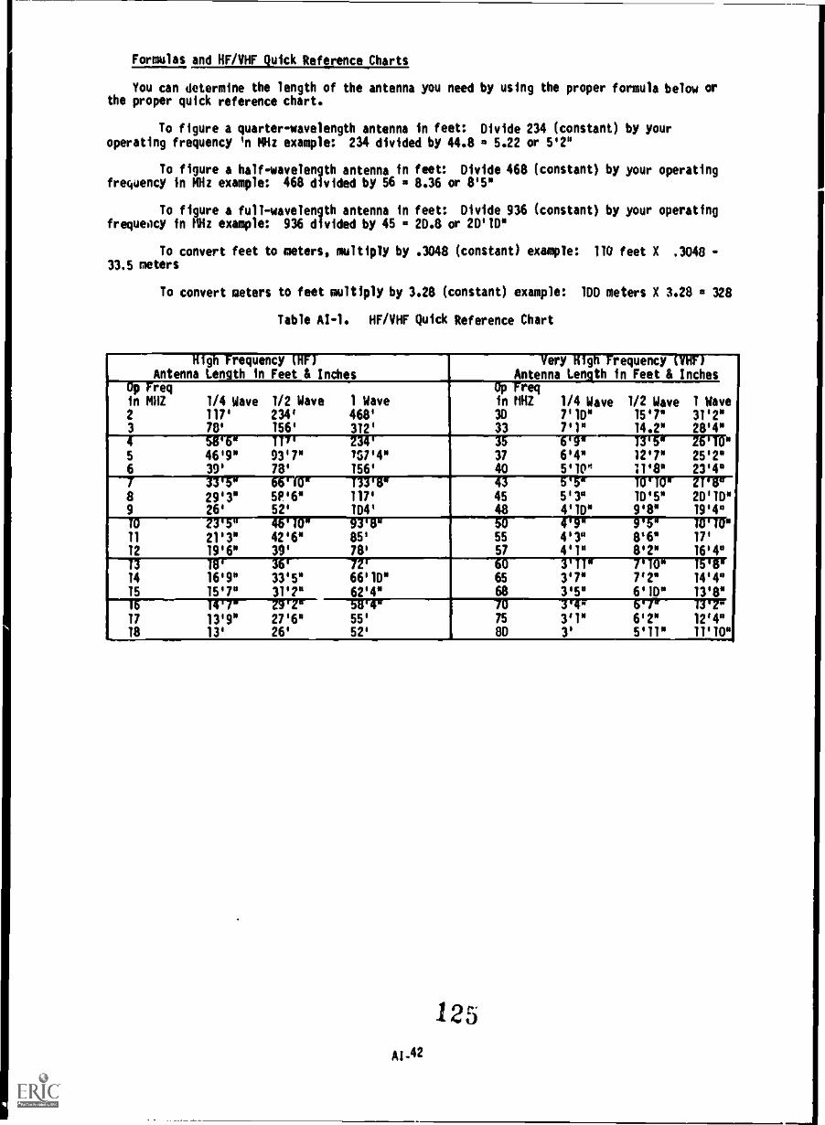
Formulas and 11F/Iilif Quick Reference Charts
You can determine the length of the antenna you need by using the proper formula below orthe proper quick reference chart.
To figure a quarter-wavelength antenna in feet: Divide 234 (constant) by youroperating frequency 'n MHz example: 234 divided by 44.8 5.22 or 5'2"
To figure a half-wavelength antenna in feet: Oivide 468 (constant) by your operatingfrequency in MHz example: 468 divided by 56 is 8.36 or 8'5°
To figure a full-wavelength antenna in feet: Oivide 936 (constant) by your operatingfrequency in MHz example: 936 divided by 45 . 20.8 or 20'10°
To convert feet to meters, multiply by .3048 (constant) example: 110 feet X .3048 -33.5 meters
To convert meters to feet multiply by 3.28 (constant) example: 100 meters X 3.28 a 328
Table AI-1. HF /VHF Quick Reference Chart
High Frequency DiFFAntenna Length in Feet & Inches
Very High Frequency (VHF)Antenna Length in Feet & Inches
Op Freqin MHZ 1/4 Wave 1/2 Wave 1 Wave
Op O Treq
in MHZ 1/4 Wave 1/2 Wave 1 Wave2 117' 234' 468' 30 7'10° 15'7° 31'2°3 78' 156' 312' 33 7'1° 14.2° 28'4°
35 6'94 -17,30-12V171"4 58'6w 117r Z34'
5 46'9° 93'7° 757'4" 37 6'4* 12'7° 25'2"6 39' 78' 156' 40 5,10" 11'8" 23'4"
8 29'3" 5P'6" 117' 45 5'3° 10'5* 20'10*9 26' 52' 104' 48 4'10° 9'8" 19'444
11 21'3° 42'6° 85' 55 4'3° 8'6° 17'
12 19'6* 39' 78' 57 4'1" 8'2° 16'4°
13 18r 36r 7Zr 60 3111w 7'104 15'8r14 16'9° 33'5* 66'10° 65 3'7° 7'2' 14'4°
15 15'7° 31'24 62'4° 68 3'5° 6'10" 13'8°16 14'7" Z9-'Z" sor4° 70 -3'44 6'7" 13'z'17 13'9° 27'6" 55' 75 3'1° 6'2" 12'4°
18 13' 26' 52' 80 3' 5'11° 11'10"
125A1-42

Field Expedient Insulators
Materials which are made up of nonconducting substances like porcelain, glass, rubber andplastic are used in antenna system construction to preven' undesired current flow paths orshort cir:uits in the system. Examples of some very common items readily available for use asinsulators for field expedient antenna systems are buttons, bottle necks, tire tubes and drycloth or rope.
Figure AI-18 below shows how these items may be used
MT* MARI° wMAST "1.31)111" ":" nal on mom DRY non
Fig Al-18. Field expendient insulators.
Table AI-2. Field Expedient Items
Here are some field expedient items that might help you get the job done in anemergency.
Original issue Field expedient
Antenna wire WD -1, barbed wire, electrical wire, coarial cableAntenna mast Trees, sticks, lance pole, telephone poleCoaxial cable WD -1, electrical wireAntenna guy rope Wire, cloth beltsGuy Stakes Rocks, vehicles, trees, tent pinsWhip antenna Wire, WD -1, coaxial cable
Pulleys Wire, nylon ropeInsulators Plastic rings, spoons, and bags, wood, rope, rags and bottles.
AI-43
12 6

Table AI-3. Field Tool Kit
The following is a list of tools and equipment which will aid in the construction anderection of field antennas.
1 each Large screwdriver set with sizes of flat blade screwdriver blades, 1 Phillipsblade and 1 awl stored in handle.
1 each Small screwdriver set, Jeweler's size, similar to above item.
1 each Lonanose pliers.
1 each Pliers.
1 each Miniature flashlight using 1 size AA cell, with 2 spare bulbs.
1 each Nickel - cadmium AA cell.
1 each Cleaning brush, electric shaver type.
1 each Compass, button type.
1 each Magnifying glass.
3 each Oil capsule, clear color.
8 each Stick pins, for use with indoor antennas.
1 each Eraser.
1 each Cleaning cloth.
2 each Plastic electrical tape stripe.
2 each Pipe cleaners.
1 each Aluminum foil, 6 x 6 inches, for Jumping fuses.
10m Receiving antenna wire.
1 each Key, socket head screw; do 11 hex short arm keys. (Allen wrench)
1 each Tweezers, Craftsman.
1 each Wrench, open-end.
1 each Pen-knife.
1 each Dikes (wire cutter).
1 each Drill (hand).
1 each Soldering torch (pocket type).
1 each Solder (small spool).
1 box Metal screws H.
1 box Machine screws #4-40.
1 box Nuts 04.
1 box Washers 04.
1 box Solder Lugs N.
127
AI-44

Table AI -3. Field Tool Kit--continued
1 box Nails.
1 box Hammer.
lm Insulated wire #18.
5m Coaxial line (50 ohm).
4 each BNC connector.
30m Nylon twine.
6 each Break up Insulator.
1 each Water pipe clamp.
1 each Broadband Balun.
6 each Alligator Clip.
1 each 6" Crescent wrench.
A1-45 128

APPENDIX II
ELECTROMAGNETIC COMPATIBILIITY ANALYSIS CENTER (ECAC) CAPABILITIES AND SERVICES
BACKGROUND
The effectiveness of the command, control, and communications system, the ability of thesystem to respond to a rapidly changing tactical situation will determine the degree ofsuccess on the modern battlefield. The growing importance of effective communications systemshas increased the requirement for accurate and timely communications-electronics engineeringanalysis support for combat units. The Joint Chiefs of Staff (JCS) has established support tooperational units as the highest priority of the Electromagnetic Compatibility Analysis Center(ECAC). Operational support is defined as the "Communications-Electronics (C-E) engineeringanalysis provided by ECAC to the Joint Chiefs of Staff, Unified/Specified Commands, andoperational commanders to assist in the execution of their mission." Operational support tothe Marine Corps consists of providing C-E engineering analysis support to Marine Corps unitsto ensure the efficient use of C-E equipment resources and to attain compatibility with theenvironment.
ECAC has been providing operational support to the Marine Corps since 1973. Much of theanalysis support has been on a rapid-response basis to requests by Marine Corps communicationspersonnel during exercise or contingency planning. Some of the exercises the ECAC hassupported include: KANGAROO II, June 1976; 3D MAW JAVELIN, Oct 1976; RAVEN BUTTE, Feb 1977;BOLD GUARD and NORTHERN WEDDING, Sep 1978; and MAGEX 80, Korea, 1980. Examples of long termexercises that EdAC has supported are: TEAMWORK 76 and 80, DISPLAY DETERMINATION 77 and 79,and the SOLID SHIELD series. ECAC-CB-77-051, entitled RAPID RESPONSE OPERATIONAL SUPPORT TOTHE U.S. MARINE CORPS, and published in August 1977, described the operational supportanalyses available to the U.S. Marine Corps. Since then these analyses have been upgraded andthe responsiveness to Marine Corps operational units has been increased.
OBJECTIVE
The objective of this report is to describe the various analytical capabilities and inputdata required for Marine Corps c.:....moilications-electronics engineering and electromagnetic
compatibility support.
Note: Appendix II is professional reference material designed to enhanceyour abilities ONLY; this information is not tested in this course.
12,9All -1

OPERATIONAL SUPPORT
OPERATIONAL SUPPORT ANALYSIS CAPAGIUTIES
The C-E Annex (Annex K), to the Operation Plan/Order is developed by identifying the C-Eequipment and personnel resources needed to support the commander's concept of operations.The anticipated physical and electronic environment is then ilentified and an assessment madeas to how the environment will affect the unit's ability to accomplish its mission. ECACprovides operational support by assisting Marine Corps units in identifying the physical andelectronic-environment and then providing analysis support assessing the effect of theenvironment on the unit's ability to accomplish its mission. The following are representativeof the types of operational support analyses that are provided to Marine Corps units on aregular basis:
1 Radio line-of-sight coverage overlays.*2 C/E equipment signal coverage overlays.*3 HF skywave propagation charts.(4) HF groundwave propagation predictions.(5) 4/3 earth terrain profiles.(6) Point-to-point multichannel circuit reliability.(7) Limited frequency analysis.
* Indicates that digitized tropagraphic data is required to provide the analysis.
ECAC's data base contains digitized topographic data obtained from the Defense MappingAgency for the following general areas: CONUS, Hawaii, Southern Alaska, Korea, NorthernCanada, Canadian and Mexican border areas, most of Europe, Mediterranean coastal areas andlarger islands, Persian Gulf area, the other Middle Eastern Countries, and Southeast Asia.Other data blocks have been requested from the !+efense Mapping Agency (DMA) and will be addedto the ECAC data base upon completion of the digitizing process by DMA.
LINE-OF-SIGHT (LOS) COVERAGE OVERLAYS
LOS coverage overlays indicate the radio LOS around radio and radar equipment. Thisanalysis is especially useful in choosing antenna location for tactical radios, microwaveterminals, and other LOS communications equipment. Figure All -1 is an example of a contoured
radio LOS coverage overlay for a tactical transmitter. Tick marks on the contour lines pointto the areas in which there is radio LOS to the transmitter. Radio LOS coverage overlays mayalso be produced where X's indicate no radio LOS to the transmitter and blanks indicate radioLOS. Figure All -2 is an examrle of a highspeed printer (HSP) LOS coverage overlay using X'sand blanks to indicate radio LOS. The HSP option for LOS coverage overlays takes lesscomputer time to produce and are especially useful for selecting radio relay points.Therefore, this type of output may be produced depending on the analysis requirements.Overlays are normally provided at a map scale of 1:250,000, but may be varied to meet userrequirements. Figure All -3 is an example of an LOS coverage overlay for a radar equipment.The coverage contours on figure All -3 provide a plot showing the target acquisition distanceversus azimuth for targets at various altitudes. Target altitudes may be specified above mean
sea level or above terrain. In this example target altitudes of 5, 10, 15, and 20 thousandfeet above mean sea level are specified. Radio coverage overlays are usually provided in 16"x 12" size for a 1:3,000,000 scale map, but other map scales can be provided as required. Thecoverage contours on figure All -3 represent points at which a target flying directly towardthe site, at the azimuth and altitude indicated, will first be detected. Figure AII-4 is anexample of a radar coverage overlay for a target at an altitude of 1000 feet AGL, andillustrates radar coverage when an aircraft or missile is using terrain-following tactics.The following information is required by ECAC to produce LOS coverage overlays:
All -2

SITE ID
EMBASSY STQTY UNITSDS (FT)
Fig All-1. Contoured radio
All-3
SURFACE1
ID MAP RATIO SCALE500000 1.00
line-of-sight overlay.
131

$:.4444444.44444X44Y44,444444X4AXXX4XXXAXAX4XXXXXXX44xXAXX4444XXXX444.14.44444444444444444$44X444XX44X444X444XX444X4XXXXXXX4XXXx4X4XXXX4Xt!AN4444444.444A4AX444XXANXX44X44AXXX4XX44XX4XXX4X4XXXXX44XX44XXXXXXXX,,AAAAAAAAAAAAx4xgA4X4XAAX4444444X4AXXX44XX44XX444AXXXXAXXX44XXXXX4XX,1444440.4444XX4Xx444xANA4444X44X4X4XXXX4XXxXXX444XX4XX44X44XXXAAXXXXI*AA44444414444444X44444444444XX4XX4xXXANXX4XXXX4XX XXXXAXXXX4X4XXXXXXIIAA44.444444444444444X4A4X444XXAXXXAAAA44XX44XX44X XXXX4XXX44XXXXXXXX,44 444A44444X44444444X44X444XX4XXXXXXAXXXXNAXXXXXXXX X4 XX44XXXXXXXX1
!4AA44/.44AA44A4A4444444;10444X14 XX444XX44XXAXXXXX 44X 4XXXXXXXXI44A144444A44444444A444*X444XX AN 44 XXX4XXAXXXXXXX XXX W114,14111414444404441014114 4XXX44X44 XX A AAX AXXXX4XXX 4X4 X 44X,*44.4.4444440.44444XX 410144XX4 A . AXAXXXXXXXXXXXXXX XXXX*XIA444444444 X44AXA 4X4i 4 X X XX444X X44XXXXXX4XXX44XXXXXXXXIsk,(44(4444414 41014 It 4( XX XXAAAXXANXICA XXXXXX XX4XX4441t4444444114444XX44X444XX44XX4444XXXX4AXX4 X XXX44XXx44XXXXXXXXI4A44444444444444A4XX444444444X4X XXXX4XXX44 XXXXXXXXXXXXXXXXX,14AA44X44AAAA44Xx4XAX4AxX44XX414 XXA44XX44X A XX4X4X44XXXXX4XX,04444A4444444X4X44444XX4X444XX4X X44X AX4XXX4XXX4XXX44X4XXXXXX,x.4444444141410441444444X4XXX4XXX4 # X X 4tXXXXX4XXXAXAAA4XXXXI0Av4A44444444444444444X441144XX4 XXXXXXX4XXX44XXXXXX4X,4,0444444404XX4XXXXXXX444X*4X4 TRANSMIT.'" XX4XX44441144XXXXXXXXI$44444444.4.4A4X44A444X444XX4 SITE A 4 XXXXXX44XX4XXXXXXX4tX,041 4A44444444444X44444. 44X444XXXXXXXXX4XXXAAXXXXX,!K.:444 44444444xx 444 X44XXXXXXXXXX4XXX44XXXXXXXX,$A.A4 A(4444444 X4 X4411X44XXX4XX4XXXAXXX44XXXXXXXXI'44444 A44 A 444X44X444XXXXXX4XXX44XX4AXXXX,
444 4XXXX4XX4XXX%XXXXXXX44XXXXXXXXI444 4XXAXXXAXWAXXXXXXXXX4XXXXXXXX,
A 4 KAA AXXN4XX44XXXXXX4XXXN4XXXXXXXX,,A AX4 XX44X44XXXNAXX4XXX44XXXXXXXXI04f4iA4 4X 44XXXXXX444XXXXXXXXXX44XX11XXXXXI,..AA4444 4 4 XXA X44XX44XX4XXXXXXX4X4X4444XXXXXXI0.4444444444 (444444 AXX 44XX44XX4XXXAXXX4XXX44XXXXXXXXI..1A04(444 A 44144444444 4XAXAXX44XX4XXXXXXX(4XXX4XXAxXXX4,,(44#4(44 4 441X44XX44X114 p4 tAX4XXXXXxxX4XXOXXxX4444X4t4XXXIM
Fig All -24 High-speed print radio line-of-sight overlay.
132

TARGET ACQUISITION OVERLAY
TRANSVERSE HERCATOR PROJECTION - SPHERE
SITE IDENTIFICATION: SAMPLE SITE LATITUDE: 34 DEG 15 MIN 19 SEC N SITE LONGITUDE:
118 DEG 18 MIN 40 SEC W
MAP RATIO: 3000000: 1 REFRACTIVITY INDEX: 285. ELEVATIONS EXTRACTED DY 4 POINT METHODELEVATIONS CALCULATED AT 30 SECOND INTERVALS SITE ELEV(FT):2837.00 ANTENNA HEIGHT(FT): 20.0ALTITUDES ARE ABOVE SER L:VEL INDICATES MISSING DATA X INDICATES SITE LOCATION OTHERSYMBOLS: 5 10 15 20
TARGET ALTITUDES: 5000.00 10000.00 15000.00 20000.00
Fig All -3. Radar LOS coverage overlay at multiple altitudes.

SITE ID QTY UNITS SURFACE ID MAP RATIO SCALE PROJECTIONSAMPLE PLLM DS (FT) 3 1000000 1.00 T M SPHERSIO
Fig All -4. Radar LOS coverage for terrain-following tactics.
All -6 13'

(1) Map scale (1:3.000,000 map scale will be used for radar equipment coverage unlessotherwise specified, 1:250,000 will be used for radio equipment coverage unlessotherwise specified).
(2) Site coordinates in UTM (geographic optional).a.b
is) Transmitter antenna height.
(4) Receiver antenna height (for radio equipment) or target altitude above mean sealevel or above (pond level (for radar LOS coverage).
COMMUNICATIONS-ELECTRONICS (C-E) EQUIPMENT SIGNAL COVERAGE
C-E equipment signal-coverage overlays are used to depict the signal strength around atransmitter taking into account such circuit parameters as transmitter power, antenna gains,receiver sensitivity, and topographic data describing the path. Two typical applications ofthis capability are: (1) prediction of the area of reliable communications for tacticalcommunicatiors equipment and (2) determination of the susceptibility of friendly C-E equipmentto enemy jamming/Intercept. Signal-coverage overlays are produced to scale (normally at1:250,000) and may be used directly with standard military maps. Figure All -5 is an exampleof a VHF area signal-coverage overlay. The following information is required:
- (1) Equipment nomenclature.
(2) Site coordinates in UTM (geographic optional)
(3) Site elevation.
(4) Antenna heights.
(5) Optional information if known, transmitter power, emission, receiver sensitivity.
(6) Antenna gain.
a If UTM either grid zone and square (i. e., 11SMG635845). or grid zone and full UTMcoordinates (i. e., 463500E 3684500N) must be provided.
b UN - Universal Transverse Mercator.
All -7
135

iv,
. , , ... .. weeo:' ...
4 OVERLAY CENTERX TRANSMITTER LOCATION
Fig All -5. VHF signal-coverage overlay.
J1...)
HIGHLY RELIABLECONIALINICATIONSSIGNAL GREATERTHAN -96 eke
RELIAGLECOMMUNICATIONSSIGNAL STRENGTHBETWEEN-9611 -800m
rtgUNRELIABLECOMINUNICATIONSSIGNAL STRENGTHLESS THAN-NO Ono

HF SKY WAVE PROPAGATION PREDICTION
HF sky wave propagation predictions describe the usable frequencies and the circuitreliability between a transmitter and receiver. Figures AII-G Larough 9 illustrate the mostcommon formats for ECAS HF predictions that are available to FMF units (methods A through D).Methods A and D provide the frequency of optimum transmission (FOT), take-off angle (ANG) andreliability (In S1 between two points for a 24hour period. Methods B and C providepredictions for the maximum usable frequency (MUF), FOT and the lowest usable frequency (LUF)for an HF sky wave. The following input data is required by ECAC to produce an HF sky waveprediction.
(1) Day, month, year of start and end of transmission.
(2) Transmitter site name.
(3) Receiver site name.
(4) Transmitter and receiver site coordinates in UTM (geographic optional).a
(5) Emission type.
(6) Transmitter power.
(7) Type of earth at each antenna (sea water, desert, marsh, average soil, etc.).
(8) Antenna type (whip, dipole, AS-2259, etc.).
(9) Antenna height and/or length.
(10) Remarks, HF Sky wave Propagation Prediction Desired (method A, B, C, 0). MethodA will be provided unless otherwise specified.
a If UTM, either grid zone and square (i. e., 1191G635045), or grid zone and full UTM
coordinates (i. e., 463500( 3684500N) must be provided.

METHOD A
RESULTS FOR FEB 1, 1981 TO FE8 28, 1981 10 CM FLUX 185.1 SUNSPOT f 142.0
CHERRY PT NC TO BERMUDA NAG AZS MILES KM.
34-35- ON, 77-17- OW 32-22- ON, 64-41- OW 106.38, 300.25 741.6 1193.5
XMTR: CDNSTNT GAIN .0H L
RCVR: CDNSTNT GAIN .0H L
GRD CONSTS. XMTR: COND= .0278 DIEL=15.00 RCVR: COND= .0278 DIEL=15.00
POWER- 1.00KW 3 MHZ NOISE=-148.608W/HZ TIME= 90 PERCENT L;N=47.008*HZRELIABILITIES
UT FOT 2.0 3.0 5.0 7.f 10.0 12.5 15.0 17.5 20.0 25.0 30.0 ANG
01 11.7 '.90 .91 .93 .95 .96 .75 .16 - - - 23.002 10.0 .88 .89 .92 .94 .87 .24 - - - - 24.003 8.; .86 .88 .90 .93 .64 .15 .01 -
- - -
i:1104 8.6 .85 .87 .90 .93 .57 .11 - - - .
05 8.4 .84 .86 .90 .92 .53 .09 - - - - - 25.1
06 8.2 .83 .86 .90 .92 .44 .06 - - - - - 25.007 7.1 .83 .85 .90 .131 .35 .05 - - - - -
08 6.6 .83 .85 .89 .70 .20 .02 - - - - - 1:::
09 5.9 .85 .87 .88 .54 .08 - - .0 - - 25.010 6.0 .89 .91 .91 .58 .10 - - - - - -
2:::11 9.3 .59 .81 .92 .95 .65 .02 - - - - - 24.412 13.5 .12 .86 .92 .94 .91 .51 .05 - - - 22.6
13 18.0 - - .57 JI9 .93 .91 .90 .84 .46 - - 21.414 20.5 - - .06 .76 .91 .89 .88 .87 .78 .14 - 21.1
15 21.0 - - .01 .75 .94 .91 .91 .90 .83 .14 - 21.7
16 20.4 -- - .71 .93 .91 .90 .90 .79 .06 - 22.3
22.817 19.7 - - - .70 .93 .90 .90 .89 .74 .01 .
18 19.2 - - - .75 .95 .92 .92 .91 .69 - -19 18.5 . - .03 .80 .95 .93 .93 .89 .62 - - 22.620 18.5 - - .51 .86 .96 .94 .94 .89 .69 - - 22.621 18.3 - - .70 .92 .94 .93 .92 .87 .5/ - - 22.5
22 17.7 .10 .67 .90 .94 .95 .94 .93 .84 .44 - - 22.4
F2.13
23 15.9 .92 ._4 .95 .95 .96 .95 .90 .64 .19 - -
24 13.9 .91 .93 .94 .95 .96 .94 .71 .20 - - -
CHERRY PT NC TO BERMUDA FEB 1981
Fig All -6. HF sky wave propagation prediction, method A.
13es
All -10

METHOD B
RESULTS FOR FEB 1, 1981 TO FEB 28, 1981 SUNSPOT B 142.0FROM CHERRY PT NC 34 -35 -ON 77-17-OW WTI EQUALS GMT-5TO BERMUDA 32-22-ON 64 -41 -OW LMTT EQUALS GMT-4AZIMUTHS: 98.38, 285.35 NAG AZIMUTHS: 106.38, 300.25XMTR: FREQ 2.0-30.0 CONSTNT GAIN .0 D8
PCVR: FREQ 2.0-30.0 CONSTNT GAIN .0 DOPATH LENGTH: 741.6 MILES 1193.5 KM POWER: 1.00KW3 MHZ NOISE: - -148.6 08W/HZ RSN: 47.0 OPHZ TIME: 90 PERCENT
***HOURS IN GMT *** ***FREQUENCIES IN MHZ ***
DATA IS FOR THE MOST RELIABLE MODE.
MUF(MMMM) - FOT (FFFF) - LUF(LLLL)
00 02 04 06 08 10 12 14 16 18 20 22 00+-1.-+-1.-+-1.-+-+-+-+-+-+-+-+-+-+-+-+-+-+-+-+-+-+-+
30-
28-
26:
24-
-30
-28
-26
M M H:24
22- M -22 UT MUF FOT LUFFF Mu - 1 13.6 11.7 2.0
M F F M -20 2 11.7 10.0 3.1
F F F M - 3 10.7 8.9 4.518- F F F -18 4 10.4 8.6 4.8
F - 5 10.2 8.4 5.0
A 16:M F M-I6 6 9.8 8.2 4.8
E M - 7 9.4 7.1 5.0
Q 14- -14 8 8.6 6.6 5.0
U - F M F F- 9 7.8 5.9 4.4
E 13- -13 10 8.0 6.0 2.1
N - 11 10.4 9.3 3.6
C 12- -12 12 15.2 13.5 6.2
Y -F M - 13 20.2 18.00 7.8
11- -11 14 23.0 20.5 8.8I M - 15 23.3 21.0 8.9
N 10:. F 14 M M -10 16 22.6 20.4 9.2
14 - 17 21.8 19.7 9.2M 09- M F L L L -09 18 21.3 19.2 9.1
H F F M L L L - 19 21.1 18.5 8.7
Z 08- F F M -08 20 21.0 18.5 7.8M L L - 21 20.0 18.3 6.5
07- F -07 22 20.1 17.7 4.8F L - 23 18.5 16.9 2.0
06- F L -06 24 16.2 13.9 2.0
F L
OS- L L L :25
L L L L
04- L
L
:04
03- L -03
02- L L L L L -02+-+-++-+-+-+-+-+-+-+-+-+-4.-+.4.-+.4-+-+.+-+-1.-+-+
00 02 04 06 08 10 12 14 16 18 20 22 00
UNIVERSAL TIME
Fig A11-7. HF sky wave propagation prediction, method B.
All -11
139

METHOD C
RESULTS FOR FEB 1, 1981 to FEB 28, 1981 SUNSPOT N 142.0FROM CHERRY PT NC 34-35-ON 77 -17 -OW LMIT EQUALS GMT- 5TO BERMUDA 32-22-0N 64-41-OW LMTT EQUALS GMT- 4AZIMUTHS: 98.38, 285.35 MAG AZIMUTHS: 106.38, 300.25XMTR: FREQ 2.0-30.0 CONSTNT GAIN .0 DB
RCVR: FREQ 2.C-30.0 CDNSTNT GAIN .0 DBPATH LENGTH: 741.6 MILES 1193.5 KM POWER: 1.00KW3 HHZ NOISE: -148.6 DBW/H: RSN: 47.0 D8 *HZ TIME: 90 PERCENT
*** HOURS IN GMT *** *** FREQUENCIES IN 14HZ ***
HOUR 010014UF 13.6
FOT 11.7
LUF 2.0
REL .86
HOUR 1300MUF 20.2
FOT 18.0
LUF 7.8REL .80
DATA IS FOR THE MOST RELIABLE MODE.
0200 0300 0400 0500 060011.7 10.7 10.4 10.2 9.810.0 8.9 8.6 8.4 8.2
3.1 4.5 4.8 5.0 4.8.87 .85 .85 .85 .86
1400 1500 1600 1700 180023.0 23.3 22.6 21.8 21.320.5 21.0 20.4 19.7 19.2
8.8 8.9 9.2 9.2 9.1
.75 .78 .77 .80 .82
0700 0800 0900 1000 1100 12009.4 8.6 7.8 8.0 10.4 15.2
7.1 6.6 5.9 6.0 9.3 13.5
5.0 5.0 4.4 2.1 3.6 6.2.84 .83 .83 .84 .87 .83
1900 2000 2100 2200 2300 340021.1 21.0 20.8 20.1 18.5 16.2
18.5 18.5 18.3 17.7 15.9 13.9
8.7 7.8 6.5 4.8 2.0 2.0.83 .83 .81 .83 .84 .86
MOTE: RELIABILITY FIQURES ARE CALCULATE( AT THE FOTXXX INDICATES THAT THE LUF IS GREETER THAN THE FOT
Fig All-8. HF skywave propagation prediction, method C.
All -12
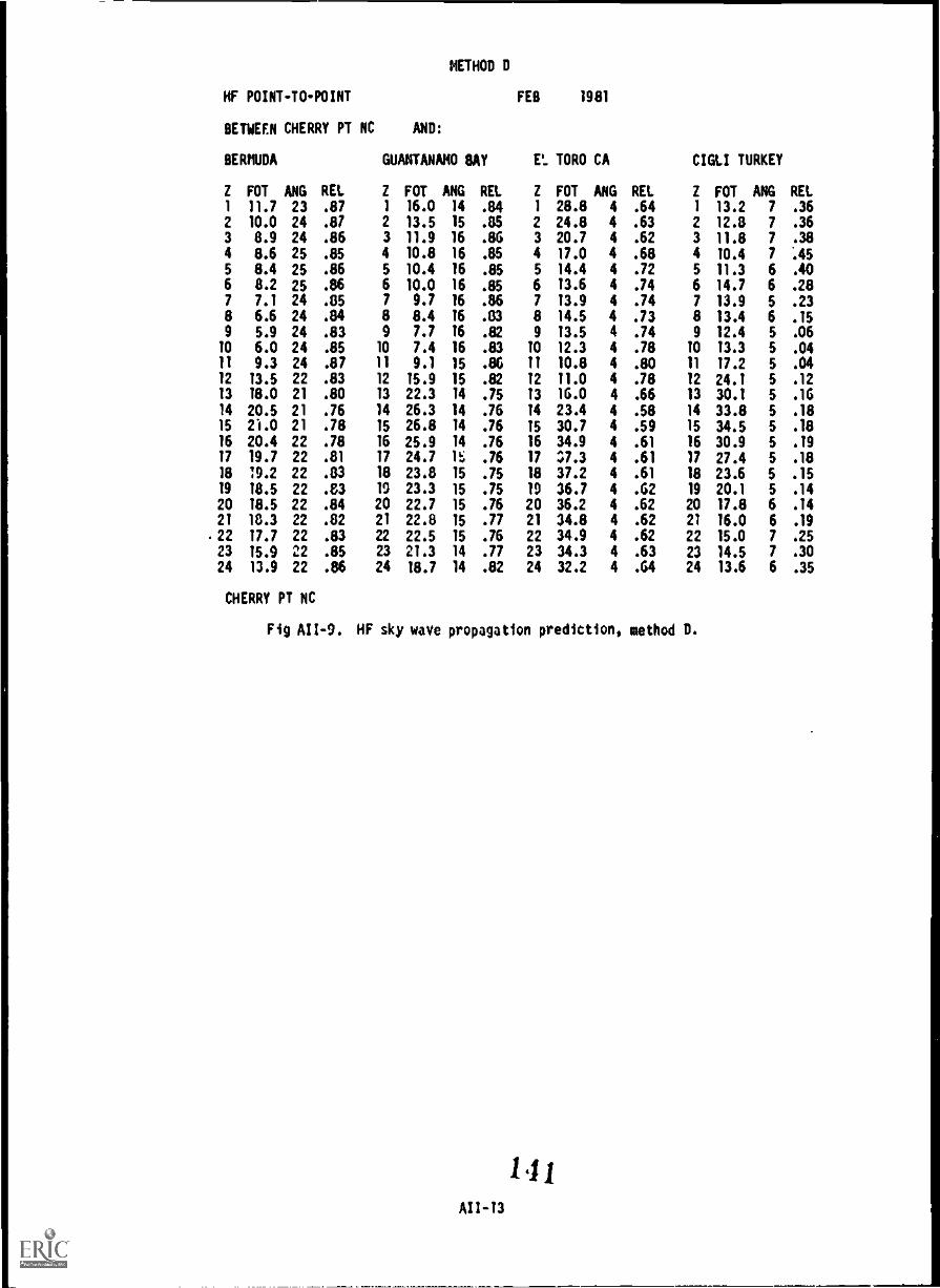
METHOD D
HF POINT-TO-POINT
BETWEEN CHERRY PT NC
BERMUDA
Z FOT ANG REL
AND:
GUANTANAMO BAY
Z FOT ANG REL
FEB 1981
Et. TORO CA
Z FOT ANG REL
CIGLI TURKEY
Z FOT ANG REL1 11.7 23 .87 1 16.0 14 .84 1 28.8 4 .64 1 13.2 7 .36
2 10.0 24 .87 2 13.5 15 .05 2 24.8 4 .63 2 12.8 7 .36
3 8.9 24 .86 3 11.9 16 .86 3 20.7 4 .62 3 11.8 7 .38
4 8.6 25 .86 4 10.8 16 .85 4 17.0 4 .68 4 10.4 7 AS5 8.4 25 .86 5 10.4 16 .85 5 14.4 4 .72 5 11.3 6 .40
6 8.2 25 .86 6 10.0 16 .86 6 13.6 4 .74 6 14.7 6 .28
7 7.1 24 .05 7 9.7 16 .86 7 13.9 4 .74 7 13.9 5 .23
8 6.6 24 .84 8 8.4 16 .03 8 14.5 4 .73 8 13.4 6 .159 6.9 24 .83 9 7.7 16 .82 9 13.5 4 .74 9 12.4 5 .06
10 6.0 24 .86 10 7.4 16 .83 10 12.3 4 .78 10 13.3 5 .04
11 9.3 24 .87 11 9.1 15 .86 11 10.8 4 .80 11 17.2 5 .04
12 13.6 22 .83 12 16.9 15 .82 12 11.0 4 .78 12 24.1 5 .12
13 18.0 21 .80 13 22.3 14 .76 13 16.0 4 .66 13 30.1 5 .16
14 20.6 21 .76 14 26.3 14 .76 14 23.4 4 .58 14 33.8 5 .1815 2i.0 21 .78 15 26.8 14 .76 15 30.7 4 .69 15 34.5 5 .18
16 20.4 22 .78 16 26.9 14 .76 16 34.9 4 .61 16 30.9 5 .19
17 19.7 22 .81 17 24.7 15 .76 17 37.3 4 .61 17 27.4 5 .18
18 19.2 22 .03 18 23.8 15 .76 18 37.2 4 .61 18 23.6 5 .1619 18.5 22 .83 19 23.3 15 .76 19 36.7 4 .62 19 20.1 5 .14
20 18.5 22 .84 20 22.7 15 .76 20 36.2 4 .62 20 17.8 6 .14
21 10.3 22 .82 21 22.8 15 .77 21 34.8 4 .62 21 16.0 6 .19
22 17.7 22 .83 22 22.5 15 .76 22 34.9 4 .62 22 15.0 7 .25
23 16.9 22 .86 23 21.3 14 .77 23 34.3 4 .63 23 14.5 7 .30
24 13.9 22 .86 24 18.7 14 .82 24 32.2 4 .64 24 13.6 6 .36
CHERRY PT NC
Fig All -9. HF sky wave propagation prediction, method D.
141All -13

HF GROUND WAVE PROPAGATION PREDICTION
The HF Ground wave Propagation Prediction provides the range, in kilometers, over which aground wave signal may be reliably rectived during a 24hour period, taking into considerationthe path distance, transmitter power, emission, antenna, and the ground constants(permittivity and conductivity) of the vertical axis, distances along the horizontal axis, anda plotted line generally running diagonally across the graph. Combinations of frequency anddistance to the left of the plotted line indicate HF ground wave communications for thatcircuit that should be reliable for any hour during the day. Combinations to the right of theplotted line should result in unreliable communications. Requests for the HF Ground wavePropagation Predictions may require that ECAC have a map (at least 1:250,000 scale or larger)of the area, in which case an additional two weeks of elapsed time will be required to providethe analysis if ECAC must order maps. Calculations used to produce the 4F Ground wavePropagation Prediction do not consider the effects of atmospheric ducting, detailedtopography, or foliage. ECAC requires the following input data:
(1) Transmitter site name and coordinates in UTM (geographic optional).
(2) Transmitter Nomenclature.
(3) Transmitter Power (watts).
(4) Emission.
(5) TransAitter and Receiver Antenna Heights (feet).
(6) Month and year of use.
a If UTM, either grid zone and square (i. e., 11SMG635845), or grid zone and full UTM
coordinates (i. e., 463500E 3684500N) must be provided.
AII-14 1 4

2.0.0
HtLIMJU
50.0
UNlit L MOLE
100.0
DISTANCE IN KILOMETERS
1 -5-
160.0 200.0
CIRCUIT PARAMETERS1. 1000%i 3KOOJ3E 32FT VERTICAL WHIP
NOTE: COMBINATIONS OF FREQUENCY AND DISTANCE TO THE LEFT OF A PARTICULAR LINESHOULD RESULT IN RELIABLE GROUNDWAVE COMMUNICATIONS: THOSE COMBINATIONS
TO THE RIGHT SHOULD BE UNRELIABLE.
Fig AII-10. NF ground wave propagation prediction.
143

4/3 EARTH TERRAIN PROFILE
Figure All-11 illustrates a terrain profile along the great-circle path between twopoints. the terrain profile shows the earth's curvature modified to an effective earth radiusof 4/3 in order to show the refracted radio ray as a straight line. Site elevation isindicated along the vertical axis and distance is indicated along the horizontal axis. Thedashed line indicates radio line-of-sight along the path. The transmitter and receiver sitename, latitude and longitude, and antenna height are indicated at the top of the terrainprofile. ECAC requires the following input date:
(1) Transmitter and receiver site name,
(2) Transmitter site coordinates in UTM (geographic Optional).a
(3) Transmitter and receiver site elevations above sea level.
(4) Transmitter and receiver antenna height.
POINT-TO-POINT MULTICHANNEL CIRCUIT RELIABILITY
This analysis provides FNF units with an estimate of the reliability of multichannelsystems prior to deployment. System reliability is predicted by determining theterrain-dependent path loss, received signal power, and estimated fade margin. The analysisalso determines whether the mode of propagation is line-of-sight, troposcatter, knife edge, orcombination of modes. Figure All -12 is an example of a reliability prediction for a number ofAN/TRC-97 paths. Data provided in the prediction include path distance, great circle azimuth,horizon angles, and the reliability percentage. The following input data is required by ECAC:
(1) Transmitter and receiver site coordinates in UTM (geographic optional).a
(2) Transmitter and receiver site elevations above sea level.
(3) Equipment nomenclature.
if OTM, pithpr grid zone and square (i. e., 1ISMG6358415), or grid zone and full UTM
coordinates (i. e., 463500E 3684500N) must be provided.
All-16
14'

10,
46
HILL 76 TO HILL 795TERRAIN PROFILE - 4/3 EARTH
TX LAT, 37-4-27 N TX LON 127-2-29 E RX LAT, 37-56-3 N RX LON 127-24-41 ETX ELEV - 249.00 FT RX ELEV - 2600.00 FTTX ANT HGT 15.00 FT RX ANT HGT - 15.00 FT
.-.%,-.
bid /.410 - - - - --Mai - -74 oi---.,
NOS
411111
DISTANCE (STATUTE MILES)
Fig All-11. 4/3 earth terrain profile.
MOO

LOS-RE - LINE-OF-SIGHT,' ROUGH EARTH, EMPIRICAL MODEL USED IF THE RAY PATH IS UNOBSTRUCTED AND NEAR THE EARTH "S SURFACELOS-FS - LINE-OF-SIGHT,' FREE SPACE (INVERSE SQUARE) LOSS IF THE RAY PATH IS UNDOBSTRUCTED AND WELL ABOVE THE EARTH"S SURFACELOS-IR - LINE-OF-SIGHT,' TRANSITION MODE, BASED ON A WEIGHTED COMBINATION OF LOS-FS AND LOS-RE PREDICTIONSKEB-S - BEYOND LINE-OF-SIGHT SINGLE KNIFE-EDGE MOOEL USING COMMON RADIO HORIZON GEOMETRYEFFKE - BEYOND LINE-OF-SIGHT MODEL FOR INTERMEDIATE REGION PROBABLY AT OR JUST BEYOND TE: RADIO HORIZONEFFRED - WEIGHTED COIIVNATION OF EFFRE AND RED NOSE WHEN RADIO HORIZONS ARE LESS THAN 2 ST. MI. APARTRED - ROUGH EARTH DIFFRACTION MODELTROSC - ROUGH EARTH TROPOSPHERIC SCATTER MODELEFFOBL BEYOUND LINE-OF-SIGHT MODEL FOR LONGER PATHS USING DOUBLE KNIFE-EDGE GEOMETERYDIFSCI - WEIGHTED COMBINATION OF RED AND TROSC MODES WHEN LOSS PREDICTIONS FROM THEM ARE WITHIN 18 DB OF EACH OTHERDIFSC2 - WEIGHTED COMBINATION OF DIFSCI AND EFFDBL MODES FOR LONGER PATHS WITH TRANSITIONAL GEOMETRYDIFSC3 - WEIGHTED COMBINATION OF TROSC AND EFFDBL MODES FOR LONGER PATHS WITH TRANSITIONAL GEOMETRY
NET SITE NAME XNTR P ****DEGREES***** PATH ANT. ANT. VTR RCVR PATH R.S.L. FADE ESTIMATE PROP DIV.FREQ 0 ANT. TRUE NAG. DIST. GAIN HGT. PWR SENS LOSS DBM MARG RELIAB NODEMHZ L ELY BRNG. BRNG. KILOM OBI fl. DBM DB 95% DB PERCENT
J1D00 SHIELD 4700.0 V -1.9 238.0 238.0 57.9 38.0 15.0 1KW -103 200.9 -67.5 35.4 >99.9994 EFFRD DUALsees
3D MAW 4700.0 V 3.1 57.6 57.6 38.0 15.0
OD
ANDRSN 4700.0 V -2.2 203.2 203.2 62.0 38.0 15.0 IN -103 150.6 -47.3 55.7 >99.9999 LOS-FS DUAL
3D MAW 4700.0 V 1.5 23.0 23.0 38.0 15.0
JEPSON 4700.0 V -2.6 72.0 72.0 40.5 38.0 15.0 1W -103 145.6 -42.3 50.7 >99.9999 LOS-FS DUAL
EAF 4700.0 V 2.2 252.4 252.4 38.0 15.0
BLK MT 4700.0 V -1.B 45.8 45.B 44.4 38.0 15.0 1W -103 155.0 -51.7 51.3 >99.9999 KEBLS DUAL
EAF 4700.0 V 1.4 226.1 226.1 3B.0 15.0
Fig All -12. Multichannel circuit reliability prediction.
146 147

(4) Transmitter and receiver antenna height.(51 Transmitter and receiver horizon angles, if critical (if not critical ECAC's
computer will calculate horizon angles from the path profile).
FREQUENCY ANALYSIS,
This analysis capability provides the requesting unit a list of frequencies compiled froma user-supplied resource list that will not cause or be susceptible to harmonic orintermodulation interference among themselves. Table All -1 is an example of such a frequencylist. Intermodulation of two-signal and three-signal products are tested for, as areharmonically interfering frequencies. The remaining frequencies from the resource list arelisted separately from the intermodulation- and harmonic-free frequencies in the order of
preference of use, if necessary. Data required by ECAC is as follows:
Table All -1. Prioritized Frequency List(all frequencies are in Pillz)
Interference-free Frequencies*30K0F3E Frequencies (10)
31.20 34.33 38.95 44.50 61.45
32.80 36.00 40.55 54.60 62.60
ORDER OF PREFERENCE OF INTERFERING FREQUENCIES
(All frequencies are in MHz)
1. 46.00 4. 34.75 7. 61.80 10. 65.40 13. 41.90
2. 65.35 5. 41.75 8. 34.75 11. 61.80 14. 46.95
3. 39.80 6. 32.15 9. 36.35 12. 60.15 15. 65.75
* All of the interference free frequencies are free of harmonic and two- and three-signalintermodulation. Of the ?interfering frequencies, those at the beginning of the list (e. g.,
46.00, 65.35, etc.) should be used first.
(1) Frequency resource listing indicating the planned emission.
(2) Radio guard chart (if required).
AODITIONAL OPERATIONAL SUPPORT SERVICES AVAILABLE FROM ECAC
Varying degrees of operational support are available from ECAC, ranging from therepresentative operational support requests discussed above to complete and total exercise or
contingency communications engineering for areas throughout the world. Analysis capability isnot limited to the previously described output, but may also consist of:
(1) More comprehensive propagation analysis (e.g., SIN and signal-level contours, skywave or ground wave comparisons, etc.).
(2) Complete listing of all frequencies currently in use for any area of interest.
(3) Antenna radiation patterns from most commonly used types of antennas.
(4) Frequency assignment recommendations (based on propagation and ENCconsiderations).
(5) Determination of antenna locations for best coverage of beaches, objective areas,or avenues of approach, or for best shielding from unwanted intercept.
(5) The most reliable means of communicating between two points.
(7) Topographic data not currently in the data base, but which may be added with
sufficient advance notice.

PlItCTICAL EXAMPLES OF ECAC OPERATIONAL SUPPORT
DETERMINING THE RADAR COV.RAGE AROUND A TACTICAL AIRBASE
Situation
A Marine Air-Ground Task Force (MAGTF) is participating in a NATO exercise which will callfor the phasing ashore of the air assests and associated air control functions. The airdefense as well as control of the airspace must be planned. The requirements ere to determinethe radar coverage around the airbase for targets using terrain-following techniques anddetermine the radar coverage for air control of friendly aircraft.
Approach
The Air Officer identifies possible radar locations for both search and fire controlradars. Target altitudes for friendly aircraft of 5, 10, 15, and 20 thousand ft above meansea level (MSL) and enemy aircraft of 1000 ft above ground level (AGL) are identified. ECACis requested to provide overlays that will show radar coverage at the specified altitudes forair control purposes and also provide radar coverage overlays for enemy aircraft usingterrain-following techniques at various altitudes. The overlays for each radar site areproduced to a scale corresponding to maps held by the MAGTF.
Required Information
(1) Equipment nomenclature.
(2) Map scale.
(3) Radar site coordinates in UTM (geographic optional).
(4) Transmitter antenna heights.
(5) Target altitudes (Friendly-MSL, Enemy-AGL).
Output,
Radar LOS coverage overlays are produced to show the radar coverage (for targets eitherMSL or AGL) from each proposed radar site. Figures All -3 and All -4 illustrate the types ofcoverage overlays that would be produced. Using these overlays the Air Officer can determinethe adequacy of the radar coverage from the proposed sites for friendly air control and fordefense against enemy aircraft. The Air Officer can then recommend radar sites based on hisanalysis or consider additional sites for analysis, if necessary.
DETERMINING THE OPTIMUM GROUND SURVEILLANCE RADAR OEPLOYMENT LOCATION
Situation
The Commanding Officer of the 2nd Battalion 6th Marines plans to deploy the battalionground-surveillance radar during an upcoming exercise. The battalion commander wants toemploy the ground surveillance radars to aid in detection of enemy forces and has instructedthe S-3 to determine the optimum location for deployment of the equipment.
Approach
By conducting a map study, tentative positions for deploying the radar are identified.ECAC is requested to provide 2/6 with radar LOS coverage overlays at a scale of 1:250,000 forthese locations. The radio LOS coverage overlays will indicate the LOS coverage from eachlocation and, conversely, show gaps in the radar coverage.
If UTM, either grid tone and square (i. e., 11SMG635845), or grid zone and full UTMcoordinates (i.e., 463500E 3684500N) must be provided.
AI I.20 1 4:)
Required Information
(1) Site coordinates in UTM (geographic optional).
(2) Site elevation.
(3) Antenna height.
(4) Equipment nomenclature.
Output
LOS coverage overlays for each proposed site are produced (figure All -13). For this radarsite avenues of approach Red and green are not under surveillance by the radar, while avenueof approach Blue is well covered. Based on the coverage from each of the proposed radarsites, the communications officer can recommend an optimum location to site the equipment.
DtTERIIINING THE LOCATION OF A VHF FM TACTICAL RADIO RELAY SITE
Situation
The Communications-Electronics Officer of the 4th MAB must ensure that ViF Fitcommunications are available between the 4th MAB headquarters and the 6th Marines CP locationsfor an upcoming exercise. The exercise play will extend the communication ranges for the VHFFM tactical radios so that LOS communications between the two CP's will not be possible. Aradio relay site needs to be selected to ensure that LOS tactical communications aremaintained.
Approach
Tentative CP locations for the 4th MAO and 6th Marines are identified. VHF radio LOScoverage overlays are requested for the proposed relay sites.
a If UTM, either grid zone and square (i. e., lIS11G635845), or grid zone and full UPIcoordinates (i. e., 463500E 3684500N) must be provided.
All -21
150

u-It v
'060404103 4tpci aouettlaws punoJ9 oft-IN 611
iXXXXXXXXXXXXXXXXXXXXXX XXXX iXXXXXXXXXXXXXXXXXXXXXXX X
iXXXXXXXXXXXXXXXXXXXXXXX iXXXXXXXXXXXXXXXXXXXXXXX X iXXXXXXXXXXXXXXXXXXXXXXXX t X X
iXXXXXXXXXXXXXXXXXXX XXX iXXXXXXXXXXXXXXXXXX XXX
i XXXXXXXXXXXXXXXXX XXXX IXXXXXXXXXXXXXX iXXXXXXXXXXXXX X
iXXXXXXXXXXXXXX X X XX
iXXXXXXXXXXXXX XX XXX iXXXXXXXXXXXX XX
iXXXXXXXXXXX XXXXXXXXX IXXXXXXXXX XXXXX XX X
iXXXXXXXX XXXXXXXXX X
iXXXXXXXX XXXXXXXXXXXX ixAXXXXx xxXxxxxxxXx ixxxxxo xxXxxxXx ixXxXx Xx xxXxXxXx XXXX ixxxx xxxxxxXxxXxXxx xxil
ixxx xxxxxxxxxxxxxxxx ix XxxxxxXxxxxxx XYxx x ix xx x xxxxxxxx xxxxxx
i xxX x x xxxxxxxxxxxxxxxxx
XXXX xx
XX
XXXXXXXXXXXXXXi xxxvxxxxxxxxi XXXXXXXXXi XXxXXxi XXXXXi
X X XXi X Xi
X xi
X
AXXX Xi XXX. XXi
XXXXX; ly1441XXXXi XXXXIWIXXXXi
XXXXX XXXXXXXXX
X XXXXXXXXXX XX XXXXXX XXXXXX
XXX XXXXXX XXXX XXXXXXXXXXi XXX XXXXXXXX XX XXXXXXXXXXXXXXi
XXXXXXXXXXXX XXXXXXXXXXXXXXXXi X XXX X x IMMIX XXX; X X xxxx xxxxxi i:x X xxxxx xxxxxxxxxxx&N
XXxXXi xxxxxi
xxxxxxxxxxx xxxxxxxxxx X xxxxxxxxxxxxxxxxxxxxxx xxxxxi
xxxxxxxxXxxxxxxx xxxxxxx xxxxxxxxxi xxxxxxxxxxxxX xxxxxxx xxxxxxxxxxi
XXXXXXXXXX XXXXXXXXXXXXXXXXXXXXXXXXXXXXXXXXXXXXXXXXX XXXXXXXXXXXi iXXXXXXXXXXXXXX XXXXXXXXXXXXXXXXXXXXXXXXXXXXXXXXXXX%XX XXXXXXXXXXXXi
iXXXXXXXXXXXXXXXX XXXXXXXXXXXXXXXXXXXXXXXXXXXXXXXXXXA XXXXXXXXXXXXi iXXXXXXXXXXXXXXXXXXXXXXXXXXXXXXXXXXXXXXXXXXXXXXXXXXX XXXXXXXXXXXXXXi iXXXXXXXXXXXXXXXXXXXXXXXXXXXXYXXXXXXXXXXXXXXXXXXXXX XXXXXXXXXXXXXXXi iXXXXXXXXXXXXXXXXXXXXXXXXXXXXXXXXXXXXXXXXXXXXXXXXX XXXXXXXXXXXXXXXXXi iXXXXXXXXXXXXXXXXXXXXXXXXXXXXXXXXXXXXXXXXXXXXXXXX XXXXXXXXXXXXXXXXXXi iXXXXXXXXXXXXXXXXXXXXXXXXXXXXXXXXXXXXXXXXXXXXXXX XXXXXXXXXXXXXXXXXXXi
i ixxxxxxxxxxxxxxxxxxxxxxxxxxxxxxxxxxxxxxxxxxxxxx l
xxxxxxxxxxxxxxxxxxxi ixxxxxxxxxxxxxxxxxxXxxxxxxxxxxxxxxxxxxxXxxxxxx xxxxxxxxXxxxxxxxxxxxxi

The LOS coverage overlays will indicate the radio LOS from each of the proposed relay sitesand will aid In selecting the site that provides radio LOS to both CP locations.
Required Information
(1) Equipment nomenclature.
(2) Map scale of the overlay.
(3) Site coordinates in UTM (geographic optional).a
(4) Transmitter antenna height.
(5) Receiver antenna height.
Output,
Radio LOS coverage overlays are produced at the scale requested (normally 1:250,000).Figures All -14 ano AII-15 illustrate the overlays produced to solve the problem of finding asuitable radio relay site. The LOS coverage overlays show that relay site A is not acceptablebecause there is no radio LOS to both CP's while site B provides radio LOS to both CPlocations. Therefcre, relay site 0 is selected as a relay for the exercise.
DETERMINING THE AREA AROUND A TRANSMITTER IN WHICH RELIABLE COMMUNICATIONS ARE POSSIBLE
Situation
The communications officer of the 8th Marines is planning the communications support foran upcoming exercise. Based on a preliminary analysis of the operation plan, he has concludedthat the personnel equipment resources of the communications platoon are inadequate to supportthe scheme of maneuver. Specifically, the plan will require that a number of VHF FM radiorelay sites be established in order to provide reliable communications from the regimental CPto the maneuver battalions. If some of these relay sites could be eliminated, thecommunications platoon could support the exercise. Otherwise, the commanding officer must beadvised that additional equipment and personnel are required.
Approach
Location, for the regimental CP are determined. Based on these locations and the possiblelocation of Jther CP's, the area in which tactical communications will be required isdefined. thing the parameters for the equipments and antennas, estimates of the transmitterpower levels around the regimental CP location can be made taking into account signal powerlosses from both terrain and vegetation. In this case a previous recon of the area has shownthat vegetation will not be significant in attenuating the transmitter signal. ECAC isrequested to provide signal-coverage overlays from each regimental CP location usingparameters representing the C-E equipment and antennas that will be deployed. The
signal-coverage overlays can be produced to indicate reliable areas of communication aroundthe regimental CP. Proposed Jneuver battalion locations will then be plotted on the overlayand a determination made as to whether reliable communications are possible between theregiment and battalion CP's. If reliable communications are possible, a recommendation couldbe made to eliminate some of the planned VHF radio relay sites.
Required Information
(1) Equipment Nomenclature.
(0 Site coordinates in UTM (geographic optionalha
(31 Site elevation.
(4) Antenna heights.
(5) Transmitter power, emission and receiver sensitivity.
(61 Antenna gain.
a If UTH, either grid zone and square (i. e. 11SMG635845), or grid zone and full UTMcoordinates (i. e., 463500E 3684500N) must be provided.
AII-23
152

OZ-IIV
.11 olls luolloatas ails Ota.4 amyl ANA IttIIV 61i
91410131HS JO 33N930 NIMONS OIN
malasassiis
is litoato atm
. Osoasola ossoanolaS
a
alas tau a
...... mast* 0000, i
00000101 Mal
....................................... 1 aillaisolaal
ttiliagaugaionalijsgao
sogagigisagassa aaaaaaaaaaaaaaaaaaa In aaaaaaaaaa ma 010 0000000 0411021.$000000aSaia01
aeaaalistoassolotoaoloalio Ha 00000 10e$ 00000 0010001020000s00000, 0000000 oosotoessotolotoaeasio e$ 0000000000000000000efireseolM10000S0a$
apnea a 020e$0111110earfteSa000 i i oaolooaaaseeemego so 81000 00000 Oto 00000000 ostosoosaa 0 0800110 0 IltmovOM100,11taralitela
illaaaaaaallaalisaaalia01011401010000 000000 mesoss000alanslio0 0000000000 ma aoloSISOlo 00000 mina Omni' 001 4110411Sassaga0000 0000000000 is 00 ins eale$11000sea MO 1010481000100000 aaaaaa 4060 aaaaaaaaa OM aaaaa ego aaaaa out
s804810080404 aS a a alloaa a a
a Pas on 0800002000000nOOMISUOI
I anatos000loaaoolosahato . asaa aas Oa aaaaa Math aaaaa o000oaStotrOsta01011001101 I
e$00200010011111
isOlialssio aaaaaa 108iOolotolo aaa a aaa saes eS sass
aims' 3 aaaaaaa 1 slat I a
00flailltlaraMailinilualillagrarallaranlialaa":1
epaatoases aaaaa loa a a a to 0 aaaaa 114311:40 liOliallialiNalliglitalineelnlii=it augutolgasselealieuasOolia
100"110e$10100001110 aaaaaa WI a a 0 aolosaosasoas soma's a we, 0sos0 0 0,0000001fleteleiel aaaaa IIMOO 4 sassassisessissasasss aaalealla aaa
all III: aaaaaaa paRs aos I mil aaaaaaaaaaaa . as a as 0 0 aaaaaa s wole$011110100aallaafatallielialool
as os a iaa'sosoloaatoostolotouto aaaaaaa mum aaaaaaaa 0 0 0 ss
PIM 000011aM1100001M0111.0101 asoloseSsaoseepoessoapoe
aaaaaaaaa latolssa wanes's. aaaaa aeolosliamaassa Ulla a Milaaaa oil Wall : 10081100011008 MI aaaaa eselOneelltalsOtlial Ossaolliefesolielliell000m
aaaaaa Masa Ionia 0111010 aaaaaaaaaa gal aaaaaaaaaaa a aaaaa 011001101010 aaaaaaa Oa' aaaaaaa 0 IOU aarell00Onlirroealre10108101 alas' toaaliso astoloaato In IMO as ma 00 00112010010111110002000012100 I
Ionia 1181.1 pm la a oentlelienanNifit": a susoosos000la 'Mamas aaaaa os p 081100 Is mom OM 0s0 11111011$001
4a sea 008 toaaostomoa to 4 sa as 6 000pOssaaamomasioesia
II to 0 lolosoos0000000080018to so0 oso Malian peals aaaaaaaa Opiate uplipiptp pp 40$1pg
114411016 a as Ala .._, $0411,200,00::::::::::spirgelsiOnt0000011110.1010al
I ;44416010 01
4010 aaaaaaa losaliaelitamosala aaaaaa alailliapaallaas
,;1441;4,,,,, .."i1.1 gesilispairiptlEaspriels1 aaa otales aaaaaaaaaaaaaa aaaaaaaaaa aaaaaa aaa illi aaaaaaaaaaaaaaaa iiiii 40 gassOliSaISSIsa011Staisisga
r alias aaaaaaa 100,0800 aaaaa 0000011101:170::::
aaatosoallaSSU'asso
a
ons malio00,0:
Is .0808
aaa ..
... aaaaaaaaaaaaaaa .....*.e..........0....

000
. t
15.5.
oilo
151111 II Ii
'I"St
ISots41
ail oh Ss IS,
.
SAGO ISIS I tVitt 55115 515 5! 5511 0:NTrn %S III. o
eye 1104 oo '
ISIS I IS0 t SS IIV/Iteff USS
et 1 hatSi S IS ?Ott o 1551 I II
etVII S S
SiViSSISi IS, 151511ill I I I(Iii Si I
lo .
SiSi i ASS
S of
tatOM
'sassamisleaavissaagsaga ssssssss ita.
S.
., Eli!SS gm 00000000 *melt It
. SMAga t 000000000 as es
. tail
. egg' 00000 mmmagmaigg a
a
. S41 04iltelfte
maws Issvet
8.
' 555
t fif
11511
sill 09111.8/11111o iiiriiii I1 445 442Tf51544
Ills 11th WImaws!
al 15171111Ii anamittsystiviNgit
Ts 1
gnawswilavilfumwarialmwswist
matte!wystgravavg,
atingaminftetlfotannsmosinsTs,
mire/taila outlasts,
t en attlastalattoil ttttt WISWWWWITI
MS ttttt Wil,41111,/,T.4
1
Si tttt stmayttswt ttttt !Ira tttttttttt lawsittnnIvit
oe Ts ,
t sywitrimillymilvvilvit
igvaiteatt,WI
.in
..mm...w.,1,..............m......... . tt.. ...4... tt
6R10 SHOWING DEGREE OF SHIELDING
Fig All-IS, VHf radio relay site selection, site B.
AII45
154
...moam4w.m.0

11"..P4
Reieived 1,1qual level (RSL) contour overlays are produced for each proposed regimental CPlocation (figure All-l6). the overlay shows the regimental CP locations and planned maneuverbattalion locations. The hashed area indicates where reliable communications from theregiment can be expected. For instance, if hattalion CP's were established at Sites A and C,reliable communications with the regimental CP would be expected. Sites B and D are in anarea of predicted unreliable communications. If planned battalion CP and relay locations arein areas of reliable communications, then the requirement for a radio relay would beeliminated. These overlays allow the user to assess areas of reliable communications againstplanned radio relay and battalion CP sites and then make a determination as to whether someplanned relays could he eliminated, thus freeing up equipment and personnel resources tosupport the exercise.
DETERMINING THE SUSCEPTIBILITY OF CE TRANSMITTERS TO ENEMY RADIO DIRECTION FINDING
Situation
The unit is scheduled to participate in an exercise in which Electronic Warfare (EW) playwill be stressed. The communications officer is responsible for ensuring that deployed C-Eequipment takes into account the ability of the enemy to conduct direction finding (DF)operations against the unit C-E transmitters. He is especially concerned about the VHF FMradio employed on the tactical circuits. The S-3 has asked that recommendations be made forCP locations that will minimize the enemy's capability of conducting successful directionfinding operations against the VHF FM C-E equipment.
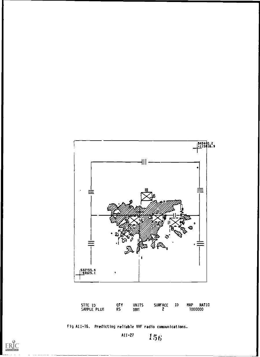
93025.1
SITE ID QTY UNITS SURFACE ID MAP RATIO
SAMPLE P1.1.11 RS DBM 2 1000000
Fig All -16. Predicting reliable VHF radio communications.
AII-271 5
A roach
Each proposed friendly CI' location is identified. The S-2 is contacted for informationconcerning possible enemy OF unit locations. Based on this location data and equipmentcharacteristics of the friendly C-E equipment and the enemy OF equipment, signal-coverageoverlays can be produced which will indicate areas in which friendly transmitters aresusceptible to enemy OF operations. ECAC is contacted and requested to producesignal-coverage overlays which will indicate the susceptibility of each proposed battalion CPlncation. The overlays are requested at a scale of 1:250,000 so that they can be used withmaps held by the unit. Ideally, CP locations can be found that will allow for tacticalcommunications between friendly units yet hinder the enemy, through terrain masking, fromsuccessfully employing his OF capability.
Required Information
(1) Equipment Nomenclature (friendly and enemy).
(?) Site coordin,tes. enemy and friendly, in UTM (geographic optional).a
(3) Site elevations (friendly and enemy).
(4) Antenna heights (friendly and enemy).
(5) Friendly transmitter power, emission and enemy receiver sensitivity.
(6) Friendly and enemy antenna gains.
Output,
Signal-coverage overlays are produced at a scale of 1:250,000 for each of the likely enemyOF locations (figure All -l7). Each overlay illustrates the ability of the suspected OF unitsto intercept the VHF FM transmitter signals from the proposed battalion CP's. Using theseoverlays, recommendations for CP locations are made to the S-3 which can limit theeffectiveness of the enemy's OF capability. In this case proposed battalion CP s'*, B wouldnot be used because of the likelihood of successful OF operations against friendly C-Eequipment at that location.
PREDICTING THE PROBABILITY OF ENEMY JAMMER SUCCESS IN JAMMING REGIMENT-TO-BATTALION COMMANDAND CONTROL AND CONTROL CIRCUITS
Situation
The Regimental Communications Officer is planning for an exercise in Europe. TheCommanding Officer is concerned that aggressor forces will jam his command and controlcircuits to the two maneuver battalions playing in the exercise. The regimental CO requestsrecommendations for CP locations that will minimize the enemy's ability to jam the regimentalcommand and control circuits.
Approach
Receivers at the battalion CP locations will be more susceptible to jamming than willreceivers at the regimental CP location because of their proximity to the enemy. Therefore,selection of hattalion CP locations will be critical in limiting the effectiveness of theenemy's jamming capability. Assuming that a reliable circuit is possible between thebattalions and the regiment, signal strengths can be predicted from C-E equipment at theregimental CP versus signal strengths from enemy jammers in the operating area and anassessment made of the effectiveness of enemy jamming signal strength will be more powerfulthan the friendly signal strength. ECAC is requested to provide J/S contour overlays for eachproposed regimental CP location.
Tentative regimental CP locations and enemy jammer locations are identified along withtechnical parameters of friendly VHF FM radios and the enemy jammers. The J/S contour
overlays will be produced to a scale usable with maps held by the regiment. A J/S ratiogreater than zero will indicate that the VHF FM radiu at that location is susceptible to being
Jammed.
4 it OM either grid znne and square (i. e., 115MG635W), or gird zone and full UTMCoordinates (i. p., 463500E 3684500N) must he provided.
All -78

Area susceptible to enemy direction finding.
Fig A11-17. Predicting susceptibility to enemy OF.
All-29
1 58

Fr liA
20
Fig All -18. J/S signal coverage overlay.
All -30
153

Required Information.
(I) Lqulpment nomenclature (friendly and enemy).
(2) Site coordinates for Regt. CP and jammer locations in UTM (geographicoptional). a
(3) Site elevation (friendly and enemy).
(4) Antenna heights (friendly and enemy).
(5) If known, transmitter power and emission (friendly and enemy).
(6) Antenna gain (friendly and enemy).
Output
J/S signal-coverage overlays are produced which show the jammer-to-friendly signalcoverage for each of the suspected jammer location (figure AII-18). Figure AII-18 shows theJ/S ratio plotted at three levels P.0, 0, and -20 dB. Tick marks point to the higher J/S ratiolevels. It also shows two proposed battalion CP locations at points A and B. If battalion CPlocation A were selected these equipments would be susceptible to enemy jamming, since theywould be located in an area in which the J/S ratio is greater than zero. The proposedbattalion CP locations at point B would be acceptable for planning purposes since the friendlyradio signals would be greater than the jammer signal resulting in a J/S ratio of less thanzero. J/S signal coverageiverlays are produced for each different regimental CP and jammerlocation. Using these overlays, recommendations for battalion CP locations that will reducethe effectiveness of the enemy's jamming capability are made.
DETERMINING THE OPTIMUM HF FREQUENCIES TO USE IN A PLANNED HF SKY WAVE CIRCUIT
Situation
The 1st Marine Brigade has a requirement to establish an HF circuit between MCAS Kaneoheand MCAS El Toro. The Brigade CEO instructs his frequency manager to determine whatfrequencies should be used on the circuit. The CEO also wants a recommendation whether the32-foot whip antenna could be ised on the circuit.
Approach
The frequency manager identifies the combinations of transmitter power, antenna, andemission that will be used on the circuit. An AUTODIN message is prepared and sent to ECACrequesting an HF propagations for the path (figure All -19).
Required Information
(1) Day, month, year of start and end of transmission.
(2) Transmitter site name.
(3) Receiver site name.
(4) Transmitter and receiver site coordinates in UTM (geographic optional).a
(5) Emission type.
(6) Transmitter power in watts.
(7) Type of earth at each antenna.
(8 Antenna height and/or length.
a If UTM, either grid zone and square (i. e., 11SMG635845), or grid zone and full UTMcoordinates UTM coordinates (i. e., 463500E 3684500N) must be provided.
All -31
1.6o

R?418071 NOVRO
FM CG FIRS! MAR HOE
TO RUEBAFA/ECAC ANNAPOLIS MO//CM//
INFO RUHQHQA/CG FMFPAC
RUHOKBA/FIRST RADBN
RUWJGFB/CG THIRD MAW
BT
UNCLAS
SUBJ: HF PROPAGATION PREDICTION REQUEST
1. 5-31 OEC BO
2. MCAS KANEOHE
3. MCAS EL TORO
4, 212712N 1574515W, 334029N 1174210W
5. 3KOOJ3E
6. 1KW
7. AVG SOIL
8. 32' WHa
Fig A1I -19. HF skydave propagation request.
Output
An HF propagation prediction is provided by AUTOOIN for the requested path (figure A11-20). Based on this prediction, the frequency manager decides whether the 32-foot whipantenna can be used on the circuit.
161

RCTUDJGZ RUEDAFA5362 3391702 0084-0000--RUHOKBA BUIIQHQA RUHUGFB.ZNR UUUUUR 0417027 DEC 80FM ECAC ANNAPOIIS MO//CM//TO RUHQKBA/CG FIRST MAR BDEINFO RUHCHOA/CG FMFPACRUHOKBA/FIRST RADERRUHOKBA/COMMSPICO SEVENTH COMMBNRUWJGFB/CG THIRD MAW81
UNCLASSUBJ: REQUEST FOR HF GROUNDUAVE PREDICTIONS (U)A. FONECON FIRST MAP BDE CEO/ECAC(SSGT ANTON/MR SKINNER) 19 NOV 80
ECAC HF IONOSPHERIC PROPAGATION PREDICTIONSMETHOD 'A'
THE ACCOMPANYING PREDICTIONS DESCRIBE THE OPTIMUM TRAFFIC FREQUENCY (FOT), THERECOMMENDED RADIATION TAKE-OFF ANGLE (ANG) AND THE PREDICTED RELIABILITY (REL) FOR THEINDICATED CIRCUIT FOR EACH HOUR OF THE DAY AS A FUNCTION OF FREQUENCY, AVERAGED OVER A30 DAY PERIOD.
MOST HF SKY WAVE CIRCUITS REQUIRE AT LEAST TWO FREQUENCIES - A HIGH 'DAY' AND ALOU 'NIGHT' FREQUENCY. IF THE RATIO OF DAY TO NIGHT FREQUENCIES IS 2 TO 1 OR GREATER,A IRANSITION' FREQUENCY WILL USUALLY BE REQUIRED BETWEEN THE TWO TO MAINTAIN THECIRCUIT DURING SUNRISE AND SUNAT.
THE FOT IS THAT FREQUENCY WHICH WILL REFLECT FROM THE IONOSPHERE 90 PERCENT OFTILL TIME. DAY AND NIGHT FREQUENCIES SHOULD BE CHOSEN THAT ARE SLIGHTLY BELOW THE DAYAND HIGHT FOTS. AS CAN BE SEEN IN THE ACCOMPANYING PREDICTIONS, FREQUENCIES LOWERTHAN THE FOT MAY HAVE AN OBVIOUSLY HIGHER RELIABILITY. THIS IS BECAUSE THE REL ISBASED ON THE PROBABILITY OF ATTAINING A REQUIRED SIGNAL-TO-NOISE-RATIO (RSN) AND ISTHEREFORE A MORE ACCURATE MEANS OF DESCRIBING OPTIMUM FREQUENCIES.
IF HIGH ACCURACY IS DESIRED, IT IS SUGGESTED THAT THESE 30-DAY PREDICTIONS BEAUGMENTED BY THE 24-HOUR PROPAGATION CONDITION FORECASTS ISSUED BY THE USAF GLOBALWEATHER CENTER OVER AUTODIN WITCH ARE BASED ON CURRENT WORLD -'VIDE IONOSPHERICSOUNDINGS.
RECOMMENDATIONS FOR CHANGES TO THESE PREDICTIONS OR QUESTIONS CONCERNING THEIRINTEPRETATION SHOULD BE DIRECTED TO ECAC'S OPERATIONAL SUPPORT GROUP (SAGO), AUTOVON:281-02452. THOSE REEVING TO PROJECT COO1DINATION OR POLICY MATTERS SHOULD BEDIRECTED TO THE DEPUTY DIRECTOR FOR MARINt CORPS (CM), AUTOVON: 281-2555.
Fig All -20. HF progagation prediction message.
All -33 1 62

PAGE 02 PUEBAFA5362 UNCLASECAC HF IONOSPHERIC PROPAGATION PREDICTIONS
METHOD A
FOR DEC 1, 1980 TO DEC 31,1980 SUNSPOT #143.0FROM KANEOHE BAY MI 21-0-12N 157-45-15WTO EL TORO CA 33-40-29N 117-42-10WAZIMUTHS: 62.1, 261.4 HAG AZIMUTHS:XIIIR: V. MONOPOLE 9.8 METERS LROM: V. MONOPOLE 9.8 METERS LPATH LENGTH: 2575.9 MILES 4145.5 KM POWER: 1000.W3 MHZ NOISE: SUBURBAN RS11: 48.0 DB*HZ LUF PERCENT: 90
Z FOT
01 31.302 27.503 23.804 20.315 17.606 15.307 13.7OU 12.2
09 11.710 11.9
11 12.412 10.813 9.414 8.915 9.216 16.1
17 25.918 35.719 38.7
20 38.321 37.022 36.023 35.624 33.9BT
2.0
-
-
-
-
--
-
-
-
-
-
-
-
-
-
--
-
-
-
3.0 5.0
- -
- -
- .01
.20
- .28
- .27
- .27
- .26
- .26
- .25
- .25
- .25
- .28
- .33
- .19
-
- -
- -
- -
- -
- -
- -
- -
- -
RELIABILITIES
7.5 10.0 12.5
- .15 .32
.08 .43 .50
.38 .64 .63
.60 .74 .59
.64 .74 .58
.62 .64 .50
.62 .64 .24
.54 .54 .15
.48 .48 .10
.52 .52 .13
.56 .58 .20
.45 .47 .15
.44 .26 .04
.44 .19 .04
.41 .24 .03
.39 .55 .48
.01 .37 .45- .08 .25- - .13- - .00
- - .06
- - .07- - .12
- .03 .19
15.0
.44
.56
.50
.56
.43
.09
.03
.03
.02
.02
.03
.02
--
-
.12
.50
.37
.26
.20
.18
.19
.25
.33
17.5
.51
.51
.57
.41
.08
.01-
-
--
-
-
-
-
.01
.49
.48
.40
.35
.33
.35
.39
.45
20.0
.54
.58
.42
.10
.03-
-
--
-
-
-
--
-
-
.54
.54
.50
.47
.45
.44
.45
.49
25.0
.29
.12
.01
-ft
-
--
-
-
-
--
-
.07
.31
.27
.26
.27
.28
.30
.31
30.0.03
.03
-
-
-
-
--
-
--
-
-_
.02
.18
.19
.18
.17
.15
.14
.1i
ANG14.614.2
14.014.1
14.314.6
14.9
15.0
15.0
14.9
15.015.4
15.815.9
15.414.3
13.2
12.7
12.9
-
-
-
-15.0
RCTUDJGZ RUEBAFA5362 3391702 0084-UUUU
Fig All -20. HF propagation prediction message-continued.
All -34

OFTFRMINING THE RELIABLE DISTANCE FOR HF GROUND WAVE COMMUNICATIONS
Situation
The 3rd Marines are scheduled to participate in a exercise in Korea, and the requirementexists to establish HF command circuits during the exercise. Since the distances of the HFcircuits are expected to be 80 km or less, it is possible that many of tne circuitrequirements could be satisfied using HF groun: gave propagation.
Approach
The regimental communications officer identifies the 3rd Marine HF circuit requirements.Transmitter and receiver locations for each circuit are identified along with the transmitterpower, emission, and antenna to be used. ECAC is requested to provide HF ground wavepredictions for each path.
Required Information
(1) Transmitter site name and coordinates, in UTM (geographic optional).a
2) Transmitter nomenclature.
(3) Transmitter power.
(4) Emission.
(5) Transmitter and receiver antenna heights.
() Month and year of use.
Output
HF ground wave propagation prediction charts are produced for each path and power,emission, and antenna combination, predicting the communicability of the path (figure A11-21). Figure AlI -21 provides a prediction of the HF ground wave communicability from Hill91 for three combinations of equipment, emission, and antenna. Using this predIction, anassessment is made whether HF ground wave propagation cal be used for this circuit.
4 If 1)114. either grid zone and square (i. e., 115%615845) . or grid :one and full UTMcoordinates (i. e.. 463500E 3684500N) must be provided.
All -35
164

1
21.
24.
=
z 18.-
15.-1it 12.-1
2 a.-
6- 8."
3.-
2.
HILL 97
L0.0 26.0 S2.0 78.0
DISTANCE IN KILOMETERS
1
104.0 130.0
CIRCUIT PARAMETERS1. PRC-47 EMISSION 3K00J3E 7511 20FT WHIP2. NRC-83 EMISSION 3K00J3E 750W 16FT WHIP3. TSC-15 EMISSION) 3K00J3E 750W 32FT WHIP
NOTE: COMBINATIONS OF FREQUENCY AND DISTANCE TO THE LEFT OF A PARTICULAR LINESHOULD RESULT IN RELIABLE GROUND WAVE COMMUNICATIONS: THOSE COMBINATIONSTO THE RIGHT SHOULD BE UNRELIABLE.
Fig All -21. Hill 97 ground wave prediction.
ESTIMATING THE COMMUNICABILITY OF VHF FM COMMUNICATIONS PATHS FOR CONTINGENCY PLANNING
Situation
The CCEO of the 1st Marine Division is concerned about the communicability of VHF Fitcircuits for various contingency plans that the division may be required to support. A rapidassessment of the communicability of each pain and determination of which paths will requirefurther analysis is required.
Approach
VHF FM transmitter and receiver locations for each path are identified. The equipment andantennas to be used on each path are identified. ECAC is requested to provide a 4/3 earthterrain profile for each path, indicating the radio LOS along the path. A rapid assessment asto the communicability of the path can be made by identifying whether radio LOS is possiblefrom the transmitter to the receiver. Those paths that do not have radio LOS will beidentified for further analysis.
Required Information
(1) Transmitter and receiver site c. me.
(2) Transmitter and receiver coordinates, in UPI (geographic optional).a
(3) Transmitter and receiver site elevati,).s above mean sea level.
(4) Transmitter, and receiver antenna height.
Output
Four-thirds earth terrain profiles are produced for each path similar to the example infiqdre All -9. The profiles will indicate whether there is an LOS along the pat and will alsoprovide a visual presentation of the profile. From the terrain profiles an estirste of thecosrunitability of each path is made, and those paths requiring further analysis areidentifiei.
4 if WTM, either grid zone and square (i. e., 11SMG635845), or grid ?one and full UTMcoordinates (i. e., 463500E 3684500N) must be provided.
A11-361 6 5

PREDICTING THE RELIABILITY OF PROPOSED MULTICHANNEL CIRCUITS
')ituation
The 1st MAW is planning an exercise in Korea and has identified the requirement forseveral AN/TRC-97 microwave circuits. Lift requirements for the exercise are being computed,and a determination needs to be made as to whIther the AN/TRC-97 assets allocated for theexercise will be sufficient. An estimate of the circuit reliability needs to be obtained inorder to determine if additional AN/TRC-97 equipment will be required.
Approach
The proposed transmitter and receiver site locations for each circuit are determined.Since equipment planned for the lift needs to be identified within a matter of days, anAUTOD1N message is sent to ECAC requesting a reliability prediction for each circuit. ECAC isrequested to provide, by return message, an estimate of the reliability of each circuit.
Required Information
(1) Transmitter and receiver site coordinates in UTM (geographic optional).a
(2) Transmitter and receiver site elevations above mean sea level.
(3) Equipment nomenclature.
(4) Transmitter and receiver antenna height.
output
Each path is analyzed, and an AUTUMN message is sent back to the 1st MAW with an estimateof the reliability of each path (figure A11-22). Additionally, planning parameters for eachpath are provided to include a recommended power and a recommendation for diversity ornon-diversity operation. The path from Hill-76 to Hill-307 has a predicted reliability ofless than 50 percent. From this information the CEO directs that a relay site be planned forthis link, thus requiring an adjustment in the lift requirements.
DEVELOPING AN INTERFERENCE -FREE MULTICHANNEL FREQUENCY ASSIGNMENT PLAN FROM A RESOURCE LIST
Situation
The division has a training exercise planned for the near future. A list of trainingfrequencies that may be used during the exercise has been obtained from the area frequencycoordinator. The frequency assignments may cause interference to VHF FM multichannelassignments.
Approach
The frequency resource list for VHF FM frequency assignments for the exercise isidentified along with the VHF FM circuit requirements. Based on this information ECAC isrequestee to develop do interference -free frequency plan for each site, so that themultichaunel wisignments could be used simultaneously with single-channel assignments withoutsuffering or causing interference. The frequency resource list will be checked for harmonicas well as two-signal and three-signal intermodulation products, and an interference-free list
will be developed.
Required Information
(1) Frequency resource list (Including planned emission).
(?) Radio guard chart.
Diltput
The result of the ECAC analysis is an interference-flee frequency resource list similar tothe frequency list in table A11-1. ECAC can also be requested to make multichannel frequencyassignments. Figure A11-23 is an example of a frequency assignment plan developed for a 1stMarine Division VHF multichannel system.
AII-37
166

RCTUDJGZ RUEBAFA5266 3451500 0050 - UUUU-- RUI9ANA.
7NR UUUUUH i01c00/ DEC 80EN ECAC ANNAPOLIS MD//CM//TO RUEBANA/ CG FIRST MAWBT
UNCLAS
ECAC MICROWAVE RELIABILITY PREDICTIONSMETHOD E
THE PREDICTIONS PROVIDE THE NECESSARY INFORMATION FOR SETTING UP MICROWAVECOMMUNICATIONS CIRCUITS AND ARE PRESENTED IN A FORM SUITABLE FOR INCLUSION INCOICUNICATIONS PLANS. INCLUDED FOR EACH CIRCUIT ARE THE PATH DISTANCE, GREAT CIRCLEAZIMUIHS, HORIZON ANGLES, RECEIVED SIGNAL LEVEL FOR 95% OF THE TIME, THE CALCULATEDRELIABILITY PERCENTAGE AND THE PROPAGATIO3 MODE.
THE RELIABILITY IS THE PERCENT OF TIME THE RECEIVED SIGNAL MEETS OR EXCEEDS THEREQUIRED SIGNAL-TO-NOISE RATIO DURING 9S% OF THE TIME. ALTHOUGH RELIABILITIES LESSTHAN 99% CAN OFTEN BE TOLERATED FOR STRAIGHT VOICE TRANSMISSIONS, A MINIMUM OF 99.99%IS USUALLY CONSIDERED NECESSARY FOR MULTIPLEXED TRANSMISSIONS.
FOUR PROPAGATION MODE (PM) ABREVIATIONS ARE USED IN THIS METHOD:L -LINE OF SIGHTD -DIFFRACTION
C -DIFFRACTION-SCATTER(COMBINATION OF DIFFRACTION AND TRO"1SCATTER)
T -TROPOSCATTERE -EFFECTIVE DOUBLE KNIFE EDGE
DIVERSITY CODES (DIV) ARE: S-SINGLE Q-QUAD D-DUALRECOMMENDATIONS FOR CHANGES TO THESE PREDICTIONS OR QUESTIONS
CONCERNING THEIR INTERPRETATION SHOULD BE DIRECTED TO EC\C'S OPERATIONALSUPPORT GROUP (SAGO), AUTOVON: 2B1 -2452. THOSE RELATING TO PROJECT COORDINATION ORPOLICY MATTERS SHOULD BE DIRECTED TO THE DEPUTY DIRECTOR FOR MARINE CORPS (CM),AUTOVON: 201-2555.
PAGE 02 RUEBAFA5266 UNCLASECAC MICROWAVE RELIABILITY PREDICTIONS
METHOD E
FREQ
NET SITE MHZ*********** *****
H-76 4700H-307 4700
H-76 4700
H620 4700
P DEGREES ANT0 ANT MAG DI ST XMTR GAINL ELY BRG KM. PWR DBI* **** ***** **** ****** *****
V .5 9.8 113. 1KW 38.0V 2.4 189.9 38.0
V .0 13.6 115. 1KW 38.0V -.4 193.B 38.0
BT
RCTUDJGZ RUEBAFA5266 3451500 0058-UUUU
PSL95% FADE PERCENT P I
DBI1 IIARG RELIAB. M V***** **** ******* * *
-11.9 ****(50.0000 T D
-57.8 45.2)99.9999 D D
Fig All-22. Multichannel reliability prediction message.
All-30 1 6

1st MARD1V MRC-135 ASSIGNMENT
Fig All-23. 1st MARDIY VHF multichannel assignment plan.
All-39
168

OBTAINING ECAC SUPPORT
Request.. for yipoort should be directed to:
Marine Corps Deputy Director (CM)ECAC, North SevernAnnapolis, Maryland 2140?AUTOYON: ?81-?555Commercial: (301) ?67-2555
Messages should be sent via AOTODIN to "RAC ANNAPOLIS MD/ /CM/ /" To expedite ECM;support, requests for support from the field can he made by telephone to either the MarineCorps Deputy Director or the Operational Support Team (AUTOYON 281-2452), if unclassified.The date by which the material is needed should also be included.
ANALYSIS RESULTS
Results of analyses may be transmitted in various ways. The method that provides thefastest .esponse is to send results via teletype (AUTODIN). The following types of analysescan be transmitted via AUTODIN:
(1) 4/3 Earth Terrain Profile.
(?) HF Sky wave Propagation Charts.
(3) HF Ground wave Propagation Charts.
(4) Microwave Reliability Pred1,:tions.
(5) Frequency Analysis.
Onclassifico results may also be transmitted via telecopier. If it is required that theresults be sent via telecopier, the name of the point of contact and the commercial andAOTOVON number should be provided. If analysis results must be mailed, the requesting commandshould allow 5-7 days for delivery. Analysis results will always be sent via AUTODIN whereverpossible.
FUNDING
Operational support provided to requesting commands can fall into two general categories,classified by ECAC as nonrecurring and recurring efforts. Nonrecurring efforts that take theform of consultative or short-term analyses requiring one man-week or less will be provided atno cost to the Marine Corps, subject to the approval of tO Director, ECAC. Funding will berequired from the operational command for efforts for which the estimated manpower exceeds oneweek.
Questions regarding funding should be addressed to the Marine Corps Deputy Director,Electromagnetic Compatibility Analysis Center (ECAC) Capabilities and Services.
GmEANMENT PRINTING OFFICE 19 A S 4 6 1 6 4? t Q 0 71
A11-40

BMW COURSE conga MIRA= mumT&E-1
COASE WOO COL1RSE rmsXVIE
SCCIAL swam MEIER
1. Use this form for any questions you mey have about the course. Write out your question andrefer to the study unit, work unit, cc study question with which you are having problems.Complete the self-addressed block an the reverse side. Before nailing. fold the Dome and stapleit so triat NCI's address-is 'booing. Additional sheets may be attached tD this side of the form.
NY QUE311001 IS: OUR ANS:ER 1$t
SliadOURE (TITLE OR RANK)a9IUDENr: Detach and retatn this portion.
DATA RECULRED BY TNE PRIVACY ACT OF 1974IS U.S.C. S22)
1. AMTNORTTY: Title S. USC, Sec. 301. Use of your Social Security Number is authorised byExecutive Order 9397 of 22 Nov 43.
2. PRLCIPAL PURPOSE: Tice Student Course Content Assistance Sequent is used to transmit infor-mation owernirq student participntion in MCI courses.
3. Mums use: This information is used by MCI personnel to research student inquiries. Insame cases information contained therein is used to update correspondence courses and individualstudent records maintained by the Marine Corps Institute.
4. MRNDATORY OR VOLONFARY maw= AND 1ST= ON INDIVIDUAL Mr PN3VIDINO DIFORMATION:Disclosure Is voluntary. Failure to provide information My result in the provision of incompleteservice to your inquiry. Failure to provide your Social Security NUmber will delay theproosssing of your assistance rawest.
170

INSTRUCTIONS TO STUDENT
1. Fold so that MCI address is outside2. Insert course number in square marked "Course Number"
below
3. Seol with scotch tape or one staple4. Mail to MCI
BUSINESS REPLY MAILMr OAR KEW it INN ISINNINEPIO a C
MIME 1111111111001111 V& IAMBS COM
UNITED STATES MARINE CORNMARINE CORPS INSTITUTEP.O. 50X 1775ARLINGTON, VA 22223
171
IMMI1MININ1
1MIMIMM=1
1111111111111110111111111111111111111111111111111111

S mem RKIJOrr/ Dan RY OATS SW:t. I - RI4 Y DATE RECEIVED AT NCI:
EOLTSI 141411134 1 COURSt TITLE
gar
CO4PLLTE ALL PORTICOS CF =TIM I
Section 1. student Identification
I I I I
glatiA7ADDREs!:
UNIT CODE (RI)
I __IL_ 1
114SIRUCTICNS: Print or type name, rank,and address clearly. Include 21P COOL.Only Class III Reservists may use civilianaddress.
EIPCOIX
Section 2. CM= 41141 APPIMPRIATE SOX MO FILL IN 711E APPROPRIATE SPACES.
FOR KUMAR AND CLASS II MECUM MARINES THIS ',MMUS? SE SIGNED SY THE °ammo= arrIco ORHIS MOMMOVTATIVE, i.e. TRAINING NOD.
1. (21 =WRETCH - Please grant an extension. sE ONLY(Will not be granted if already on extension., i. D
2. NOTICE OF COME CEPIMITICI4 Final Exam Sent 2. On SIC Rt LOn . (4PW exam will be sentif tows rot received at NCI.) 3. C
3. REDIROLIMENT Student has course motorists 4. It(See para. 4003 of Vol. I of NCI Catalog
for information on reensollsent.) S. Q
4. OVERDUE MAL EXAM Last (Review) lesson 6 rsent or . Please send exar.
5. C:1 Please send new ANSWER SHEETS.
6. (:) Please send missing course materials (Notincluded in course package.)..essons OtherPlanus I
7. ClaiNiat - Rank NamSocial SecurifTWaiiRUC
MOM=i. OTHER lexi,lain)
Note: This form will Mt tnreturned by PCI. If requestis valid, transaction will SIGHAAMETITLE OP RANKshow on next UAR or on OUST Pt CO OP REPRESENTATIW14C1-1t:_ form.
Am.
STUDEW Detach and retain this portion.
ftft .41.
7. E
DATE CO/PELTED
ORIGINATOR CODE
DATA REQUIRED BY THE PRIVACY PCT OF 19 74
(S V.S.C. S22h)
1. AVTIOASTY1 Title S, USC, Sec. 301. Use of your Social Security NuMber is authorised byExecutive Order 9397 of 22 Nov 43.
2. PRIHLIPAL PURPOSE: The Student Course Content Aivastamoe Request is used to transmit infor-mation Oonceening student participation in PCI courses.
3. NWT= USE: This infornstaon is used by C1 perSon1 to research student inquiries. Inscr cases information contsased therein is used to uplatk correspondence courses and individualstudent records maintained by the Marine Corps Institute.
4. RANDRMR11 OP VOLUNTARY DID:WS/JAE AND EFFECT ON morvituAL NOT PROVIDING INFORMTIMVisclo5ure is voluntary. Failure to provide information few result in the provision of inccrileteservice U your inquiry. Failure to provide your Social Secs; ity tarter will delay theprocessiini of your assistinoe MUNK.
1 7 4+4

...M a a a
[BUSINESS REPLY MAILMT OAS KW NO MN 1MIEVA/11011 S. C
11011111111 VOI 1111 MO IA' UAL MOS WA
UNITED STATES MARINE CORPSMARINE CORPS INSTITUTEP. O. BOX 1775ARLINGTON, VA 22223
11=NIMIMOMIIIMMEINDMMINOMINIMMIN
14 0UM IllSII Ili Is I Ili I 1 I is !lass 11 sm cis IIusIIMM. 4IMIO OM allym ma, ololo ammo ill 1=111 IMM OM MEI IMPID OM 4IIIm - mff Iftlim MO OM 10
uETACH BEFCRE MAILING
173