document resume - eric · document resume. ed 060 200 vt 014 775. ... occupational curriculum...
TRANSCRIPT

DOCUMENT RESUME
ED 060 200VT 014 775
AUTHOR Borgen, Joseph A.; Davis, Dwight E.TITLE An Investigation of Systems Designs and ManagementTechniques with Implications Toward a SystemsApproach to Curriculum Development and Evaluation inOccupational Education As Part of the Phase IIReport.
INSTITUTION Joliet Junior Coll., Ill.SPONS AGENCY Illinois State Board of Vocational Education andRehabilitation, Springfield. Vocational and TechnicalEducation Div.PUB DATE May 71NOTE 65p.AVAILABLE FROM Illinois Occupational Curriculum Project, JolietJunior College, 1216 Houbolt Avenue, Joliet, Ill.60436 ($1.50)
EDRS PRICE MF-$0.65 HC-$3.29DESCRIPTORS Community Colleges; *Curriculum Development; DecisionMaking; Formative Evaluation; *Junior Colleges;Management Systems; *Models; Program Development;Program Evaluation; Research Projects; ResearchReviews (Publications); *Systems Approach; SystemsDevelopment; *Vocational EducationIDENTIFIERS Illinois Occupational Curriculum Project; IOCPABSTRACT
As part of the Phase II report of the IllinoisOccupational Curriculum Project, this document sumnarizes effortsmade to: (1) gain a familiarity with the terminology and theory ofsystems modeling, (2) study the application of systems modeling invarious management settings, and (3) identify factors to beconsidered in selecting and developing a systems modeling techniquefor use by occupational administrators. Ultimately the contentn ofthis report will be combined with data gathered in two other majorareas of investigation to form the basis for the development of asystem model and related guidelines for occupational curriculumdevelopment and evaluation. Findings, based on a review of theliterature and the opinions of consultants, include: (1) Thedevelopment of a model should involve the identification of factorsrelating to the occupational curriculum, whether within theinstitution or outside the institution, and relating these factors toeach other and to the curriculum system as a whole, and (2) Theselection of a modeling technique shou3 4 consider the purpose themodel will serve. After careful consiaeration, it was decided thatthe flow chart modeling technique using Logos language would be usedfor this project. Related documents are available as VT 014 774 andVT 014 776 in this issue, and ED 050 270. (Js)

0(2090 0 3

US. DEPARTMENT OF HEALTH.EDUCATION & WELFAREOFFICE OF EDUCATION
THIS DOCUMENT HAS BEEN REPRO-DUCED EXACTLY AS RECEIVED FROMTHE PERSON OR ORGANIZATION ORIG-INATING IT POINTS OF VIEW OR OPIN-IONS STATED DO NOT NECESSARILYREPRESENT OFFICIAL OFFICE OF EDUCATION POSITION OR POLICY
AN INVESTIGATION OF SYSTEMS DESIGNS AND MANAGEMENT TECHNIQUESWITH IMPLICATIONS TOWARD
A SYSTEMS APPROACH TO CURRICULUM DEVELOPMENTAND EVALUATION IN OCCUPATIONAL EDUCATION
As Part of the Phase I I Report
"The Development of Systems Models forDecision-Making in Occupational Curriculum Development
and Evaluation"
PRINCIPAL INVESTIGATORS: Joseph A. Borgen, DeanOccupational & Technical Studies
Dwight E. Davis, Curriculum Coordinator
PROJECT COORDINATOR: David A. Anderson., Ed.D.
RESEARCH COORDINATOR: Urban T. Oen, Ph.D.
ILLINOIS OCCUPATIONAL CURRICULUM PROJECTJoliet Junior CollegeJoliet, Illinois 60436
May, 1971
The Research reported herein was performed pursuant to a contractwah the State of Illinois. Board of Vocational Education andRehabilitation. Division of Vocational and Technical Education,Research and Development Unit. Contractors undertaking projectsunder such sponsorship are encouraged to express freely theirprofessional judgment in the conduct of the project Points of view oropinions stated do not, therefore, necessarily represent official Board ofVocational Education and Rehabilitation position or policy.
4.
1
STATE OF I L LI NOISBOARD OF VOCATIO NAL L'IDUCAI1ON AND REHABILITATION
DIVISION OF VOCATIONAL AND TECHNiCAL EDUCATIONRESEARCH AND DEVELOPMENT UNIT

ACIMLEDGMENTS
The principal investigators wish to acknowledge the services
of a number of people for their valuable contributions; to the project.
The contributions were made in several different ways; in particular,
written reports, valuable information gained both in formal consultant
contractual services and in informal discussions concerning the project,
and in terms of personal referrals to other individuals and sources of
information. Althouph it is not possible to list every individual who
was involved in the project in some way, the project staff wishes to
make special acknowledgment to the following: Dr. Jacob Stern, Associate
Professor of Vbcational and Technical Education, Uni-versity of Illinoisz
Dr. Pichard Stowe and Dr. Thomas Schwen, Audio-Visual Center, Indiana
University;. Dr. Fobert Heinich, Professor of Education, Indiana University;
Dr. Leonard C. Silvern, President of Education and Training Consultants Co.,
Los Angeles- Dr. Joseph Arnold, Dr. Gregory L. Trzebiatowski, Dr. Desmond L.
Cook, and Dr. John R. Shea, The Ohio State University; Dr. T. Antoinette
Ryan, Researcher/Professor, The University of Hawaiiz Dr. Paul V. Braden,
Acting Director of School of Occupational and Adult Education, !..4r. Richard
W. Tinnell, Technical Education Instructor, and Dr. Donald S. Phillips,
Head of Technical Education, Oklahoma State University.
Joseph A. Borgen
Dwight E. Davis
ii
PREFACE
This report focuses on one area of emphasis undertaken by the
Illinois Occupational Curriculum Project in developing a model for
occupational curriculum development and evaluation. It is only a part
of the .total Phase I/ report on the research and development project
entitled The Illinois Occupational Curriculum Project, heretofore
referred to as the Research and Development Project in Occupational
Education entitled "The Development of Process Models for Decision-
Making in Curriculum Development and Evaluation." This project is
currently in progress at Joliet junior College, Joliet, Illinois,
with present efforts directed toward the initial development of a
systems model designed to assist administrators in decision-making
related to the development and evaluation of occupational education
programs. The project is funded by the State Board of-Vocational
Education and Rehabilit--ation. Drivision.of Vocational and Technical
Education, Research.and Development Dnit,-State of Illinois.
Purpose of the Project
-This project is based on the assumption that more systematic-means
must be developed to assist curriculum planners in the development of
new programs and-the continuous evaluation of on-going programs in
occupational education.
The following ouestions serve as the basis for the project research
'and development activities:
iii
4

1. Can generalizable systems models be developed to provide
curriculum planners with a systematic decision-,making procedure
for program identification, developnent, implementation, and
evaluation?
2. Is It possible to develop guidelines for the identification and
utilization of resources and evaluative criteria in accomplishing
the acttvities specified in the systems model?
Objectives of the Project
The following are the overall project objectives:
1. To develop systems models for curriculum development and
evaluation in occupational education.
?. To develop guidelines for the utilization and application of the
systems models.
3- To test the applicability and usefulness of the systems models
in a pilot situation at selected institutions offering
occupational programs.
4. To develop a plan for dissem4nation and inservice vraining
for curriculum planners in the utilization of the systems
models.
5. To promote research in related areas.
Overview of the Total Project
The project is divided into four distinct phases. These are:
Phase I: Project Planning
Phase II: Initfal Systems Yodel Development and Prellndnary
Evaluation
Phase III: Pilot Testing of the Model
iv
Phase IV: In-depth Evaluation of the Project and Dissemination
of the Findings
Phase I focused on a review of the literature, while Phase II
involved the comrarison and evaluation of systems, models, and decision-
making and the development of a nystens model for curriculum development
and evaluation in occupational education. Phase III and Phase IV are
proposed for further development, implementation, and evaluation of the
model.
Phase I: Project Planning
Phase I was initiated March 1, 1970, with a grant of $24,550.00
from the State Board of Vocational Education and Rehabilitation. This
grant combined with $6,916.00 in local funds providing a total budget
of $31,466.00 to conduct the project through June 30, 1970.
The project planning actmvities centered around three major areas of
concern identified as being particularly important to the establishment
of a firm basis for the project:
1. Review of the literature on models for curriculum development
and evaluation.
2. Review of current thinking on the effects of planned curriculum
on social and economic conditions.
3. Study of potential consultants and resources agenci2s qualified
to assist in subsequent phases of the project.
Phase II: Initial Systems Model DevelopmentAnd Preliminary Evaluation
Phase II was initiated July 1, 1970, with a grant of $67,178.00
from the State Board of Vocational Education and Rehabilitation. This
6

Lrant combined'with $16,950.00 in local funds providing a total budget
of $64,126.00 to conduct the project through June 30, 1971.
This phase of the project focused on research and development
activities in four major areas of concern directed toward the initial
development and validation of a systems model for curriculum development
and evaluation in occupational education. The following topics served
as the focus of investigative activities 17or Phase II of the project:
1. Investigation of Management Sstems
2. /nvestigation of Curriculum Models
3. Identification of Pecision-makinf, Practices in Occupational
Education
4. Initial Model Development and Testing
Developmental efforts were executed to coordinate the findings from
the aforementioned areas of Investigation with the objective of developing
an initial systems model for decision-making in curriculum development
and evaluation.
Future Phases of the Project
TWo additional phases of this project are planned. Upon completion
of Phase II, Phase III is proposed for pilot testing the model. This
pilot test will provide orientation workshops for the application and
use of the model, field testing of the model under actual conditions,
and implementation of the model in selected institutions. Phase IV will
provide for an in-depth evaluation of the project and the dissemination
of findings to other institutions for their use in developing and
evaluating occupational curricula
vi
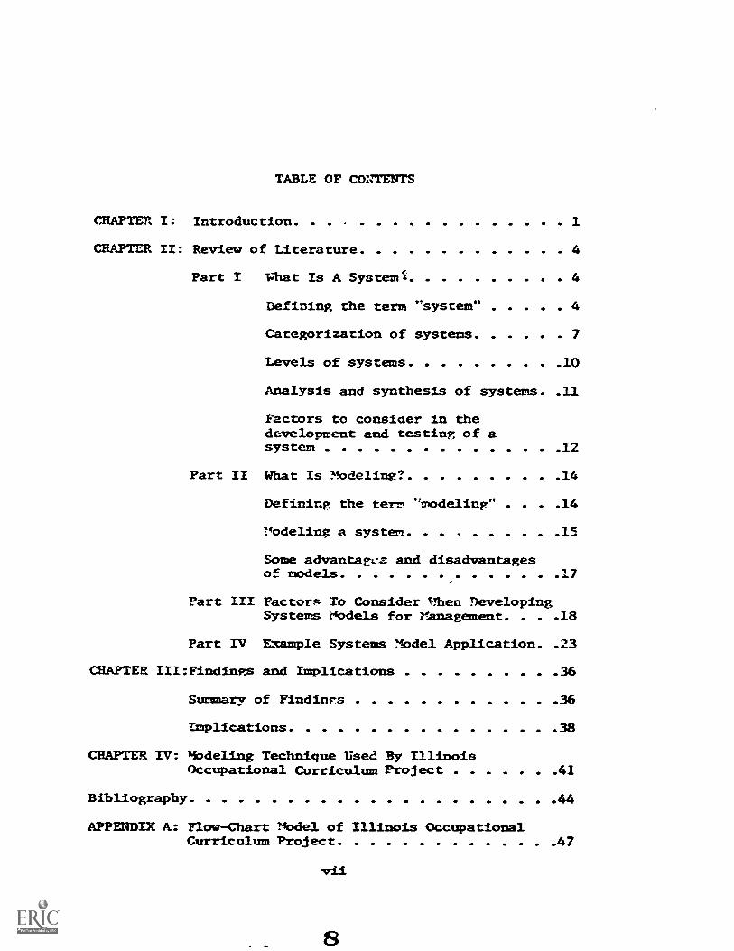
TABLE OF CONTENTS
CHAPTER I: Introduction. . 1
CHAPTER II: Review of Literature 4
Part I
Part II
What Is A Systemr4 4
Defining the term "system" 4
Categorization of systems 7
Levels of systems 10
Analysis and synthesis of systems. 11
Factors to consider in thedevelopment and testing of asystem 12
What Is Modeling' 14
Defining the term "modeling" . . . 14
T.4odeling a system 15
Same advantagt!z and disadvantagesof models 17
Part III Factortm To Consider Ilhen DevelopingSystems 74bde1s for Management. . . .18
Part TV Example Systems Mbdel Application. 23
CHAPTER III:Findings and Implications 36
Summary of Findings 36
Implications 38
Mbdeling Technique Used By IllinoisOccupational Curriculum Project 41
CHAPTER IV:
Bibliography 44
APPENDIX A: Flow-Chart Model of Illinois OccupationalCurriculum Project 47
vil
CHAPTEPIIrTgoDuctInN
As educational institutions become more complex, and the necessity
increases for accountability, there is an increasing need for a more
systematic technique for effective manapement of curriculum development and
evaluation. This is especially the case in vocational education where for
some time state plans and federal legislation have mandated chanpe in
existinp programs and expansion of progran offerins not to mention
Improvement in program output.
The vocational education amendment of 1968 strongly implied past
practices in vocational education have not been effective or comprehensive
enough to meet the needs of young people In preparation for employment.
To execute the missioa put forth in this lepislation many new programs must
be identified, developed, and Implemented to insure compliance with
contemporary needs of the student clientele and emp/over consumer.
In addition, the peed for Improved evaluation methods exists to give
d4x4.0Ligyo co the modification or tarm/nation of many on-going programs.
As stated in the preface to this report, it is the concern of the
Illinois Occupational CurrIculum Project that a more systematic method be
developed for use by local school administrators for program identification,
clevelopment, implementation, and evaluation. The assumption held by the
Illinois Occupational CUrriculum Project is that the application of systems
management teChniques to planning and decision-making can have a marked
effect on improving and expanding quality occupational programs

2
This report is intended to present one of the major areas of
investigation undertaken by the Illinois Occupational Curriculum Project to:
1. gain a familiarity with the terminology and theory
of systems modeling;
2. study the application of systems modeling in various
management settings; and
3. identify factors to be considered in selecting and
developing a systems modeling technique for use by
occupational administrators.
The contents of this report combined with data gathered in two other
major areas of investigation undertaken by the Illinois Occupational Curricull
Project will form the basis for the development of a systems model and
related guidelines for occupational curriculum development and evaluation.
Other areas of investigation are reported in the Illinois Occupational
Curriculum Project reports entitled: "An Investigation of Curriculum
Development and Evaluation Nrodels with Implications Toward A Systems
Approach to Curriculum Development and Evaluation in Occupational Mducation,
and "An Investigation of Decision-Nhking Practices in Illinois Junior college:
with Implications Toward A Systems Approach to Curriculum Development and
Evaluation in Occupational Education."
The procedure followed In completing this investigation Included the
following:
I. Review of the Literature to:
A. clarify the meaning of the term "systems",
B. Identify different categorizations of systems,
C. Identify different levels of systems,
D. identify factors to consider in the development and
testing of a system,
E. clarify the meaning of the term "modeling",
F. identify factors to consider in modeling the system,
G. Identify factors to consider when applying systems modeling
to various management problems,
show examples of systems models.
3
II. Visitations with consultants to give direction to review
literature and analysis of information gathered through this review
III. Attend conferences and training sessions on systems modeling to
gain the expertise necessary to develop a systems model for
occupational curriculum development and evaluation;
IV. With consultative assistance identify implications important for
the development of a systems modeling by the Illinois Occupational
Curriculum Project;
V. After reviewing the other Illinois Occupational Curriculum Project
reports entitled: "An Investigation of Curriculum Development and
Evaluation Models with Implications Toward A Systems Approach to
Curriculum Development and Evaluation in Occupational Education",
and "An Investigation of Decision-Making Practices In Illinois
Jumior Colleges with Implications Toward A Systems Approach to
Curriculum Development and Evaluation in Occupational Education",
and a related report titled, "The Application of Organizational
Systems Theory to curriculum Development and Evaluation",
complete the selection of a systems-modeling technique and the
development of a systems model for use by occupational administrato:

CHAPTER IIREVIEW OF LITERATURE
This chapter represents a review of se/ected literature in an attempt
to better define the terns 'systems" and Ialodeling" and identify factors
to consider in the application of systems modeling to various nanagment
problems.
Part I
Nhat is a System?
Defining the term "System'
The term "system" is now being used frequently in nearly all disci-
plines and occupational areas, for example, electronic systems, servo-
control systems, production systems, financial systens, management systems,
teaching or instructional systems, social systems, and Cybernetic Systems.
At the outset, one could surmise that "system" is either a broad term or it
is being used very loosely. The following constitutes definitions of the
term as offered by selected authors.
.R11 and Fagen(15) define a system as:
. . a set of objects together with relationships between objectsand their attributes. Objects are seen as parts or componentsof a system, attributes as properties of objects, and relation-ships as the wherewithal to tie the system together.
Ryan(31:8) defines a system as:
. . . a bounded organization of interdependent interrelated com-ponents maintained in a stable state of relatedness to each other,the total-system and the environment bY standard modes of opera-tion and feedback from the environment for the purpose of accom-plishing stated goa/s.
4
Silvern(36:1) defines a system as:
. . the structure or organization of an orderly whole, clearly
showing the interrelations of the parts to each other and to the
whole itself.
Heinich(19:4) refers to operational systems. He states that:
An operational system synthesizes and interrelates the
components of a process within a logistical framework,
insuring continuous, orderly, and effective nrosress
toward a stated goal. . .
In his book, "Instructional Systems", BanathY (4:12) defines system as:
. . . assemblages of parts that are designed and built by
man into organized wholes for the attainment of specific
purposes. The purpose of a system is realized through
processes in which interacting components of the system
engage in order to produce a predetermined output. Purpose
determines the process required, and the process will imply
the kinds of components that will make up the system.
Reviewing these definitions, one can note minor differences in terminology
and scope of the definitions. For example, Hall and Fagen refer to the
parts of a system as "objects" whereas Ryan-and others used the term
'components" to mean the same. Heinich, Ryan, and Banathy suggest quali-
fications for an effective and efficient control of a system as a part of
their definitions.
Each of the definitions reviewed show the use of the term "system"
in a generic sense referring to a whole in which components and the re-
lationship of the components to each other and to the whole have been
identified. The application of the term "system" can thus be made with
respect to any whole, natural or man-made. Silvern supports this con-
tention when he concludes "A system is what the person identifying it
says that it is" (36:;24).
13

6
Boulding (7), offers additional support when he conceptualizes general
systems theory as a skeleton of science providing a framework on which to
hang the contents of particular disciplines and areas of subject matter in an
orderly body of knowledge.
Von Bertalanffy(40,4l)further points out that there are models,
principles and laws which are generalizable to systems without regard for
the nature and relation of the elements.
All of this is not meant to suggest that there is a lack of general
principles and theory that apply to all systems. Ryan(3X:8) states that
systems can be characterized as:
1. organized and orderly:
2. comprised of objects, elements or components and relation-
ships among components and between components and the whole;
3. functioning as a whole by virtue of interdependence of its
parts;
4. synthesized in an environment to accomplish progress to a
goal: and
5. possessed of structure, function and development.
Ryan(31:9-10) goes on to offer four general principles that have been
applied to the study of operating systems or in the design of a new system.
Principle 1: The greater the deRree of wholeness inthe system, the more efficient the system --In any system, some degree of wholeness must exist.Wholeness is defined by the degree to which everypart of the system related to every other part insuch a way that a change in one part causes achange in other parts and in the total system. . . .
14
7
Principle 2: The preater the degree of systematization,the more efficient the operation of the system --Systematization refers to degree of strength in thesignal paths or relationships among parts of the
system. In a system in which the parts are onlyloosely tied together, replacement or retooling ofsystem parts may be in order If the desired level oftightness in the system is to be achieved. . . .
Principle 3: The greater the degree of compatibilitybetween system and environment, the more effectivethe system -- Compatibility refers to the extent towhich a system is geared to a particular environment.A system should be constructed In such a way as tomatch a given environment.
Principle 4: The greater the degree of optimization,the more effective the system -- Optimization is
defined as the degree of congruence between systemsynthesis and system purpose. A system should beadapted to Its environment in such a way as tosecure the best possible performance for a givenpurpose.
Categorizations of Systems
From the writings of the authors providing definitions of systems
it is also apparent that systems can be categorized as natural or man-made.
Scientists have long devoted their efforts to the better understanding of
such natural systems as the solar system, weather system, plantlife and
aniviel systems. They have formulated theories as to the components of
these systems and relationships of these components to each other and to
the whole.
Man has also constructed systems in an attempt to order the components
of a production process, training program, research study.,lett-. Examples
of man-made systems will be presented later la this chapter.
Literature also establishes that in theory systems can be categorized
as open and closed. A system is closed If there is no exchange of energies
or materials in any form, such as, information, heat, taxi physical materials
between the system and the outside envtronment.
15
8
A closed system may also be referred to as an independent system or a
system having a closed boundary.
Authors studied offer no real examples of closed systems which
suggest that most systems do not exist independent of some import or export
of information, objects, etc. However, for analysis many systems or
aspects of these systems are considered as closed systems.
Open systems on the other hand are ones in which there is an exchange
of materials, energies or Information between the system and its environment
and may be called a dependent system. For example, living systems
(animal or plantlife) are open, characterized by intake and output of
both matter and energy, achievement and maintenance of steady homeo-static
states, increasing order over time, and transactional commerce with the
environment (2).
Forrester (12:15-18) writing about the importance of structure in a
system offers the following four significant hierarchies of structure:
1. Closed Boundary
2. Feedback Loops
- The behavior models ofinterest are generatedwithin the boundaries ofthe defined system. Whatcrosses the boundary is notessential in creating thecauses and symptoms of theparticular behavior beingexplored.Within the boundary, the systemis seen as one composed of feed-back loops. Every decisionexists withii . one or moresuch loops. The loopsinteract 4:o produce thesystem behavior.
16
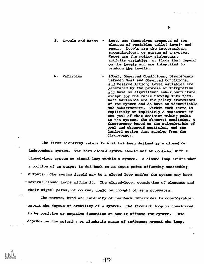
3. Levels and Rates - Loops are themselves composed of twoclasses of variables called levels andrates. Leve:s are the integrations,accumulations, or states of a system.Rates are the policy statements,activity variables, or flows that dependon the levels and are integrated toproduce the leve/s.
4. Variables (Goal, Observed Conditions, Discrepancybetween Goal and Observed Conditions,and Desired Action) Level variables aregenerated by the process of integrationand have no significant sib-substructureexcept for the rates flowing into them.Rate variables are the policy statementsof the system and do have an identifiablesub-substructure. Within each there isexplicitly or implicitly a statement ofthe goal of that decision making pointin the system, the observed condition, adiscrepancy based on the relationship ofgoal and observed condition, and thedesired action that results from thediscrepancy.
The first hierarthy refers to what has been defined as a closed or
independent system. The term closed system should not be confused with a
closed-loop system or closed-loop within a system. A closed-loop exists when
a portion.of an output is fed back to an input point affecting succeeding
outputs.-The system itself-may be a closed loop and/or'the.system may have
several closed loops within it. The closed-loop, consisting of elements and
--their signal paths, of course, could be thought of as a subsystem.
The nature, kind and intensity of feedback determines to considerable.
extent the degree of stability-of a system. The feedbaCk loop is considered
to be positive or negative depending on how it affects the system. This
depends on the polarity or algebraic sense of influence around_the
17

Positive feedback has polarity around the loop such that the output
fed back to the input causes an increase in output (12:11). Positive
feedback can cause a system to become very unstable.
Negative feedback causes the loop to be poal-seeking. A departure
from the reference point or steadystate condition produces action tending'
to return the system toward an equilibrium position that is the poal.
This type of system tends to maintain a constant output with varying
input (12:11).
Locking further at the categorization of systems, one finds that the
differentiation of linear and non-linear systems exists with some authors.
Forrester (12:11) states that:
A system is non-linear if it contains a multiplicationor division of variables or if it has a coefficientwhich is a function of a variable.
According to this definition, the concern for linearity or non-linearity
would exist primarily with systems that are represented in a mathematical
form and has little application to other systems except in a very
theoretical sense.
Levels of Systems
Almoct any system that you want to identify could be considered a part
of a larger system and is also very likely made up of subparts which are
themselves systems. This brings up a problem of terminology la identifying
levels of systems.
Silvern handles this problem as follows:
A SYSTEM may be analyzed into its parts. Themajor parts of a SYSTE1, also known as themajor functions, are called SUBSYSTEMS. ASYSTEM must have two or more SUBSYSTEM. Ifit has only one SUBSYSTEM, then that SUBSYSTEMis not a SUBSYSTEM but it is the SYSTEM itself.(361=5)-

11
The SUPERSYSTEM is a whole in which the majorfunctions at the first level are SYSTEMS.Normally, the SUPERSYSTE is conceptualizedduring the process of SYNTHESIS rather thanANALYSIS. It results from an awareness anda discovery that the SYSTEM being studiedhas some relationship with one or more otherSYSTE"S and that this was unknown. Identifyinpthe other SYSTEM or SYSTEMS, relating themand combining them into a new whole, calleda SUPERSYSTEM, is the process of SYNTHESIS.(36:126).
The SUPRASYSTEM is a whole in which the majorfunctions at the first level are SUPERSYSTEMS.As in the case of the SUPERSYSTEM, normally itis the process of SYNTHESIS which produces theSUPRASYSTEM. The SUPRASYSTEM in formaleducation and training in the United Stateshas not yet been conceptualized as faras is known. (36:126).
Analysis and Synthesis of Systems
A system is identified when a boundary is established within which
everything is a par: or element of the system. These elements may then be
analyzed. Analysis requires the process of identifying, relating,
separating, and limiting When the system being analyzed consists of
objects, actions and information, techniques of analysis are applied to
the objects, actions, and information.
Silvern (36:1) defines analysis as:
The process which is the breaking down of a whole intoits parts showing the relationship of the parts toeach other and to the whole itself. A known or exisiingwhole SYSTEM, when broken down into its constituentparts or elements, meanwhile retaining a meaningfulrelation of the parts to each other and to the greaterwhole, has been 'analyzed.
Analysis is the process by-which an existing wholc is examined. After the
process of analysis it may be desirable to relate the parts identified in a
new-way. The relating of parts in a new way is the process of synthesis which
is used to create a new whole.
19

12
Silvern (36:3) defines "synthesis" as:
. . . the process of combining non-related elements intoa meaningful relationship such that the new productis a whole SYSTEM. SYNTHESIS is widely used inengineering as a synonym for invention, innovation,creation, and design. Invention is essentiallyuncontaminated by an existing system and thereforeproduces an output as the result of the process ofSYNTHESIS.
Factors to Consider in the Develo nt and Testing of a tem
The cotbination of analysts and synthesis can bring about the conceptu-
alization of a new system or modified system. This is the first step in the
process of developing a system which is illustrated in Figure 1. Once the
new relationships have been conceptualized a prototype must be fabricated.
This prototype of the new system then goes through the simulation process
in order to see how it will function in the real life operation.
The box labeled "Simulate" in Figure 1 has three parts; "test prototype",
"identify performance criteria", and "identify real life environment."
The testing of the prototype requires two sources of information; the
performance criteria (objectives) of the system, and the real life
environment in whiCh the system will operate. From the resul-s of the
simulation process the prototype will be debugged and, if necessary, sent
back to "fabrication" and then "simulation" again.
When the prototype passes the simulation test, the new operational
system is fabricated and maintained. There is a feedbadk from "maintain"
to "fabricate" for keeping the system updated and operational. When the
system ceases to be of sufficient value, it should be eliminated as shown
by the last box in the model for developing a system.
20

The maintenance and/or elimination of a system is important.
13
Sometimes
ment'
systems are used or kept in use more out of tradition rather than because
they perform a needed function. Banathy (3:12) explains
A system receives its purpose, its input,its resources, and its constraints fromits suprasystem. In order to maintainitself, a system has to produce anoutput which satisfies the suprasystem.
CONCEPTUALIZE SYSTEM
Analyze Synthesize I
f
Ir14minateSystem
1Mai=ainSystem
that:
FEEDBACK
FabricateSystem
SIMULATE
1
IdentifyPerformanceCriteria
Di Test1 Prototype1
Identify1 Real LifeEnviron
FEEDBACK
Figure 1. Flow-chart model describing the process
Silvern, L.C. Systems Enpineering of Education I:Thinking in Education. Los Angeles: Education and1968, p. 113.
21
EvaluatePrototype
of developing a system.
EVolution of SystemsTraining Consultants Co.,

14
The key criterion for evaluating a system as suggested by Bamathy is (3:13):
. how closely the output of the systemsatisfies the purpose for which it exists.
Part II
What is Modeling?
Defining the Term "'Model"
The term nmodel" is as widely used as the term "system" and more
recently the two have been used in conjunction. However, the term nmodel"
is probably not as frequently misinterpreted or used without a reasonable
understanding of its meaning as the term "system." Focusing first on the
term "model", Silvern(36:27) writes:
. . a model is defined as a conceptualization Inthe form of an equation, a physical device, anarrative or graphic analog representing a real-life situation. Consequently, the _ideal is alwaysa concept of real-life either as it is or as itshould be, and the model has a degree of fidelityappropriate to the purpose for which it is created.
Ryan's definition of a model simply states that it is an abstraction of
some aspect of the real world in an attempt to represent reality (31:27):
nodel is simply an abstraction of the realworld in an attempt to represent rPality.To build a model, ane simply selects thoseelements from the system under analysis whichone deems as being relevant to the problem.Very seldom, if ever, would such a modelcontain all the elements of the system befrigmodeled. Complex models used with electroniccomputers may represent several aspects of thereal world situation but to represent allaspects of most systems would be a prohibitivetask.
22
15
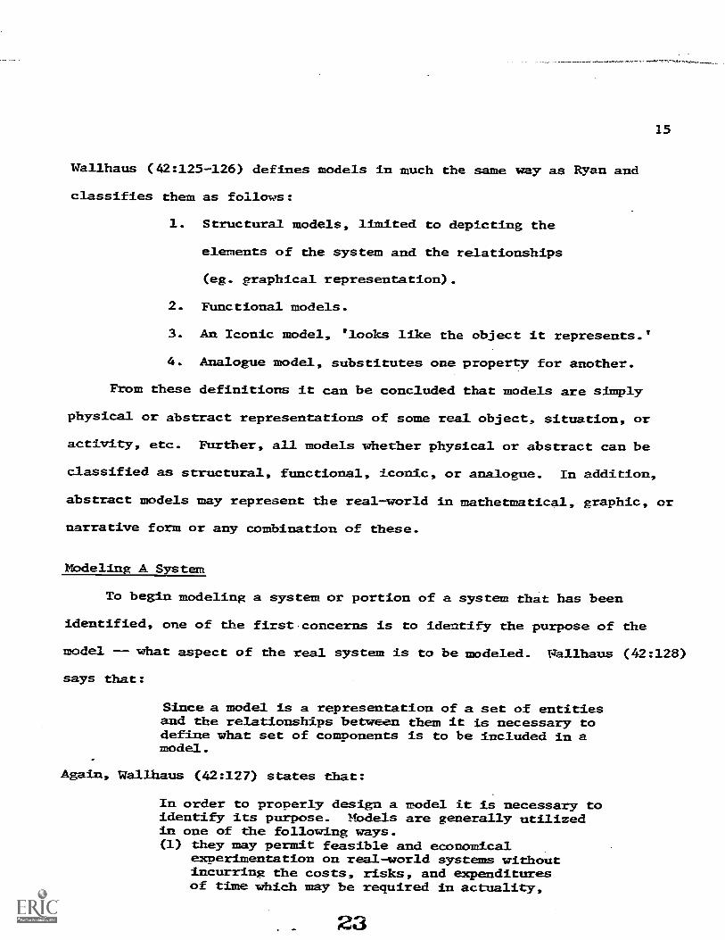
Wallhaus (42:125-126) defines models in much the same way as Ryan and
classifies them as follows:
1. Structural models, limited to depicting the
elements of the system and the relationships
(eg. graphical representation).
2. Functional models.
3. An Iconic model, 'looks like the object it represents.'
4. Analogue model, substitutes one property for another.
From these definitions it can be concluded that models are simply
physical or abstract representations of some real object, situation, or
activity, etc. Further, all models whether physical or abstract can be
classified as structural, functional, iconic, or analogue. In addition,
abstract models may represent the real-world in mathetmatical, graphic, or
narrative form or any combination of these.
Mbdeling A System
To begin modeling a system or portion of a system that has been
identified, one of the first.concerns is to identify the purpose of the
model -- what aspect of the real system is to be modeled. Wallhaus (42:128)
says that:
Since a model is a representation of a set of entitiesand the relationships between them it is necessary todefine what set of components is to be included in amodel.
Again, Wallhaus (42:127) states that:
In order to properly design a model it is necessary toidentify its purpose. Models are generally utilizedin one of the following ways.(1) they nay permit feasible and economical
experimentation on real-world systems withoutincurring the costs, risks, and expendituresof time which may be required in actuality,
23

16
(2) they allow us to formulate, communicate, anddiscuss hypotheses,
(3) they bring about an understanding of thesystem variables and their relationships,
(4) they make it possible to forecast andproject for planning and decision making,
(5) they allow control of the time scale. Real-world processes occur over long periods oftime. Nbdeling can allow long time intervalsto be collapsed, and
(6) they enable us to control and monitor real-world processes.
Another concern in constructing a model, especially a mathematical model,
is how to represent or quantify and relate the variables. The data to
feed the model is very important. For the model to operate properly the
data must be of sufficient type, quantity and quality. Concerning this
Kilbridge, et al, 22) points out that:
-models without data are-sXerile. What is needed is notmerely more data but the right data in the right form.To collect or record data meaningfully requires at leasta working hypothesis as to how It will be used; withoutthis, there is no rationale for deciding what data tocollect, no principle for ordering the data, oncegathered. To be useful, data must be kept over timeso that it can be used for trends, time series, andcomparisons.
To this Wallhaus (42:129) adds this word of caution:
The model cannot be data driven, that is, entirelyinfluenced by what data are available; but it Isunrealistic to construct a model and then hope thatthe necessary data can be obtained.
Once the model is developed, the success or validation of a model must be
in terms of the original purpose of the model. McKenney (20 states that:
The criteria for success is: Does the model fulfill itspurpose/ The issue of "Is the model true or not"may be dormant since the important question is: Willit allow reasonable estimates of an anticipatorynature. . . . Whether a model has prGclicted or notis often a function of what the predietion is tobe used for-
24

17
Concerning validation, Vallhaus (12:136) concludes that:
In summary, validation attempts to prove thatthe model is a reasonably true representationof reality within the context of its purpose.While a number of techniques for accomplishingthis verification have been identified. .
the state of the art is something less thansatisfying.
Simulation is a means of validating a model. The Webster's Collegiate
Dictionary has defined simulation as: "to assume the appearance of
without reality."
A simulator would be a device and may be a model but simulation is a
process, therefore, It should not be confused with the model itself.
Silvern (36:121-122) points out that processing data through a model
using simulation can serve two different functions. First the model can
be tested and debugged by using valid data. Also, a model that has been
validated to represent real-life can be used to test new ideas or
experimental data.
Some Advantages and Disadvantages of Models
Assuming that the model is a valid representation of some aspect(s)
of the real uorld system, the question may be asked: What is the real
utility of the model or the process of modeling? This would, of course,
depend on the nature and use of the system being modeled. In neneral,
Kraft and Lotta (23:28) cover not only the main advantages but also some
principle dfsadvantages of using models as listed below. The following are
the main advantages of using models la systems analysis:
1. Models provide a simplified abstraction of acomplex real -lorld problem.
2. Models proVide a frame of reference forconsideration of the problem.
25

18
3. Models sometimes suggest inform*tion gapswhich before were not immediately apparent.
4, Models provide a "handle" to evaluate andstudy complex problems.
5. The construction or attempt to construct amodel forces one to truly analyze as manyof the real world attributes as possible.Sometimes this very process may provideinsight which was otherwise camouflaged orunnoticed.
6. Models provide something which can be man-ipulated.
7. Models often-provide the least expensiveway to accomplish objectives.
Some limitations or disadvantages of using models, to mention a few,
wlould be as follows:
1. Models are subject to the usual dangersencountered in dealing with abstractions.For example, the model may be greatly over-simplified and/or not a valid model of thedesired object system.
2. The syMbolic language used to represent amodel may not lend itself to being stretchedto encompass the model.
3. Some people have a tendency to become "hung-up"or infatuated with a model; and, as a result,their effectiveness in offering a solution tothe problem becomes very limited.
Part III
Factors to Consider When DevelopingSystems Models for Management
The previous two parts of this chapter have attempted to define the
common use of the terms "system" and "model". This part deals with con-
siderations important to the manager when consieering the use of systems
models to organize and control various activities or functions.
26

19
Discussing management George (13:4) points out that:
Every activity which we undertake involves an element that bringscoordination or cohesiveness to the activity. Without thiscohesiveness our acts would be ineffective stumbling, perhaps
random and unproductive. This element that infuses plan and
objective as well as cohesion to activities may be called
management.
According to this definition, management ranges from coordinating very
simple to very complex activities. This coordination may include receiving,
sorting, translating, and directing information. Very simple manaeement
would be a low level of processing information and handling information,
and there may be very little information involved. The more complex and the
greater the number of activities that are involved under one manager, the
D.:ore complex the management will be.
George (13:4) sums up a concise definition of management as foltoxrs:
Management consists of getting thinss done throughothers; a manager is one who accomplishes objectivesty directing the efforts of others.
Some management may take a great deal of technical knowledge, per:eption,
understanding of world-markets, understanding of finances, supply and demand,
etc. Other management will be limited to a very narrow technical field or
very simplistic types of operation. Since management is getting things done
through others, it can be concluded that the development of systems models
for use by managers irrespective of the management activity must reflect a
concern for the capabilities of the persons involved with the system.
George (13:15) goes on to state that the total job of a manager is to:
. . create an environment conducive to the performance ofacts of other individuals. (1) to achieve a collective goal(commonly called the firm's goal), and (2) to achieve oneor more of the goals of the participating individuals.
27

20
Due to the complexity of modern day business, industry, schools, gyvernment.
and other organizations, the systems approach to management has gained a
good deal of attention in recent years.Banathy (4:13) offers a description
of the systems approach to management when he states:
The system approach appears to be the application ofthe systems view, or systems thinking, to humanendeavors.
George (13:27) similarly writes:
The systems approach is one in which the things to be managedand the tasks of management are viewed as a unit - as a set ofelements so interrelated that they form an organic whole.
It should be noted that George clearly points out that the things to be
managed and the tasks to be managed mmst be considered as a unit to identify
the boundary of the system to be modeled.
Not only does the systems approach to management include the identifying
and relating parts within the whole system, it i also concerned with the
larger system, "supersystem" which indicates that management systems are
open systems. Notice al.-;o that George and McGregor refer to an organic
system. McGregor (26:40) states that:
An indnstrial organization is an organic system. It is adaptivein the sense that it changes its nature as a result of changesand the external system around it.
McGregor (26;41) also emphasizes the human aspect of management and refers
to the industrial organization as a socic-technical system. He explains
this term as follows:
. an industrial organization is a socio-technical system.It is nct a mere assembly of buildings, manpower, money, madhines
and processes. The system consists in the organization of peoplearound various technologies. This means among other things thathuman relations are not an optional feature of an organization -they are a built-it; property. The system exists by virtue of themotivated behavior of people. Their relationships and behaviordetermine the inputs, the transformations and the outputs ofthe system.
21
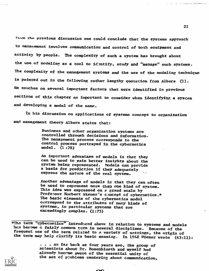
rxout thg previous discussion one could conclude that the systems approach
to manaxement involves communication and control of both equipment and
activity by people. The complexity of such a system has brought about
the use of modeling as a tool to ieantify, study and "manage" such systems.
The complexity of the management systems and the use of the modeling technique
is pointed out in the following rather lengthy quotation from A/bers (1).
He touches on several inportant factors that were identified in previous
sections of this chapter as important to consider when identifying a system
and developing a model of the same.
In his discussion on applications of systems concept to organization
and management theory Albers states that:
Business and other organization systems arecontrolled through decisions and information.Tbe management process corresponds to thecontrol process portrayed in the cyberneticsmodel. (1 :78)
An importavt advantage of models is that theycan be used to gain better insights About thesystem being represented. Nbdels can providea basis for prediction if they adequatelyexpress the nature of the real system.
Another advantage of -models is that they can oftenbe used to represent more than one kind of system.This idea W2S expressed on 2 grand scale byProfensor Norbert Wiener's c'ncept of cybernetics.*The basic elements of the cybernetics modelcorrespond to the attributes of many kinds ofsystems, In particular systems that areexceedingly complex. (1:75)
*The term "cybetnetics" introdnced above in relation to systems and modelshas become a fairly common term in several disciplines. Because of thefrequent use of the term related to a variety of settings, the origin ofthe term may help clarify its basic meaning. In 1948 Plener wrote (43:11):
. . as far back as four years ago, the group ofscientists about Dr. Rosenblueth and myself hadalready bewme aware of the essential unity ofthe set of rzoblems centering about communication,

-22
Cybernetics Is concerned with the communication and controlproblems necessary to achieve some purposim. Control ispartly a problem of feedback which provides self-regulatIonthrough a comparison of the system's output with apredetermined standard. The input into the system maybe modified if there is too mch variation from theoutput norm.
Control in the cybernetic model may also beexpressed in terms of the theory of information. A-
system can be conceived as a mechanism for handling '-
Information (1:75).
Vith the development of electronic computers and large data banlc;kNct.
information, more complex management systems can be modeled and ntudied.
These computers can process data for models representing several aspects of
a complex system.
In talking about electronic computers and the systems concept Albers
(1-:76) states that:Elaborate models that simulate environmental andorganizational realities can be used to test alternativeplanning stratesaes. The large variety of planning:problems can be solved through resource allocation,inventory, quetang, and other kinds oE mathematical models.Analogue models such as PEET have played an important partin planning and controlling highly complex projects. Business
game models have been used wete=ively for purposes ofexecutive development with a significant amount ofsuccess.
*control, and statistical mechanics, whether in the machineor in living tissue. On the otfier hand we were seriouslyhamper by the lack of unity of the iitezaiture concerningthese problems, and by the absence of any common terminology,or even of I single name for the field. After much consider-ation ye have come to the conclusicn that all the existingterminology has too heavy a bias to one side or another toserve t.7-2.1 future develoent of the field as well as Itshould; and as happens so often to scientists, we have beenforced to coin at least one artificial neo-Creek expressionto fill the gap. We have decided to call the entire fieldof control and communication theory, whether in the machineor in the animal by the name- Cybernetics, which we formfrom the Creek xtrAgesnillit or "steersran."
30

23
Part IV
Example Systems Model Application
The application of the systems approach to management has yielded many
example models from business, education, the military, etc. In reviewing
specific models there is little to be learned since each was developed for
a specific purpose and situatton. Consequently, the purpose of this section
is not to compare and contrast various systems models, but rather to simply
show selectexamoles..of systems model applications.
To begin with a very simplistic model would be the mathematical
equation:
where
= LITH
= volumeL = lengthW = widthH = height
This is a mathematical model representing the relationShips of the volume of
a rectangular container to the dimensions of the rectangular container.
This model serves very satisfactorily When the dimensions are known and
when it is desired to find the volume. Also, the equation can be transposed
so that if volume is known and two dimensions are known, the third
dimension can be found. Within its limited purpose this mathematical model
Is a very accurate representation of the system ( a rectangular container ).
However, the model cannot be used to determine- ratios of the sides to eadh
other or to predict any other characteristics of the container as a system.
If the length needs to be twice the width and the height onehalf of
the width, then the equation must be modified to accurately represent the
container.
31
24
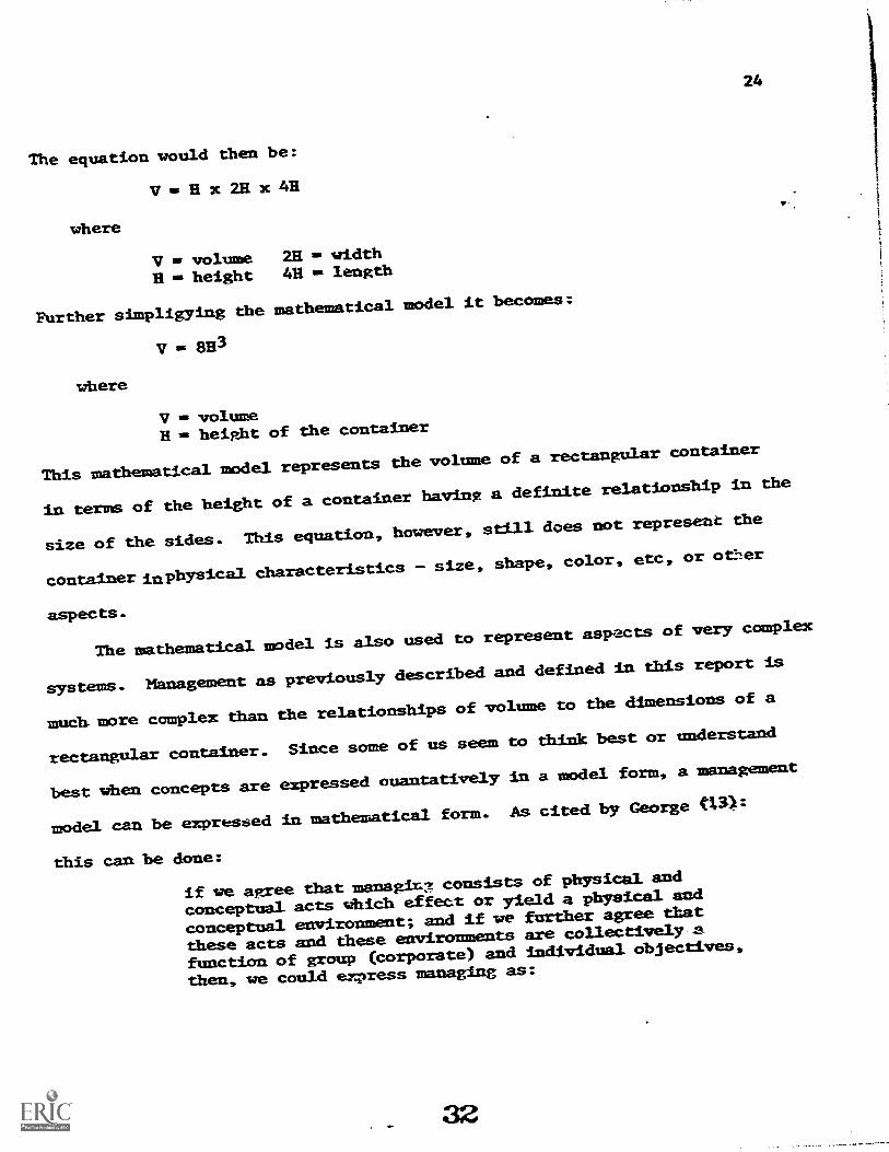
The equation would then be:
where
VesHx2Rx 4H
V = volumeH = height
20 = width411 = length
Further simpligying the mathematical model it becomes:
V =
where
p.
V = volumeH = height of the container
This mathematical model represents the volume of a rectangular container
in terms of the height of a container having a definite relationship in the
size of the sides. This equation, however, still does not represent the
container imphysicalcharacteristics - size, shape, color, etc, or ot27.er
aspects.
The mathematical model is also used to represent aspects of very complex
systems. Management as previously described and defined in this report is
much more complex than the relationships of volume to the dimensions of a
rectangular container.Since some of us seem to think best or understand
best when concepts are expressedouantatively la a model form, a management
model can be expressed in mathematical form. As cited by George
this can be done:
if we agree that managb .consists of physical and
conceptual acts Which effect or yield a physical and
conceptual environment; and if we further agree that
these acts and these environments are collectively
function of group (corporate) and individual objectives,
then, we could express managing as:
32
where
Ng = EAc + Ap)------) (Et + Ea f (01, Og)
Ac = conceptual actsAp = physical actsEt = conceptual environmentEp = physical environmentOi = individual objectivesog = group (corporate) objectives
25
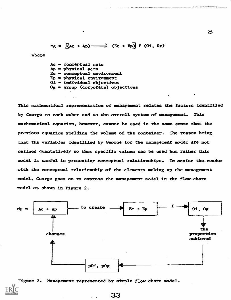
This mathematical representation of management relates the factors identified
by George to each other and to the overall system of management. This
mathematical equation, however, cannot be used in the same sense that the
previous equation yielding the volume of the container. The reason being
that the variables identified by George for the management model are not
defined quantatively so that specific values can be used but rather this
model is useful in presenting conceptual relationships. TO assist the,.reader
with the conceptual relationship of the elements making up the management
model, George goes on to express the management model In the flow-chart
model as Shawn in Flgure 2.
Mg= Ac +Ap
changes
to create Ec + Ep H
poi. Fog 14
theproportionadhieved
Figure 2. Nhnagement represented by simple flow-chart model.

26
This model points out some of the basic factors that cco into the
management model and their relationship. This model does not, however,
show administration channels of authority or lines of responsibility
time, resources, etc. Recall that when a system is modeled a specific
aspect of the system is normally identified as a point of concern and that
asnect only is modeled. The success of the model then depends on the degree
that the model represents the aspect of the system being modeled. In this
case, the donce77.m was to relate the general factors of which management
consiszs.
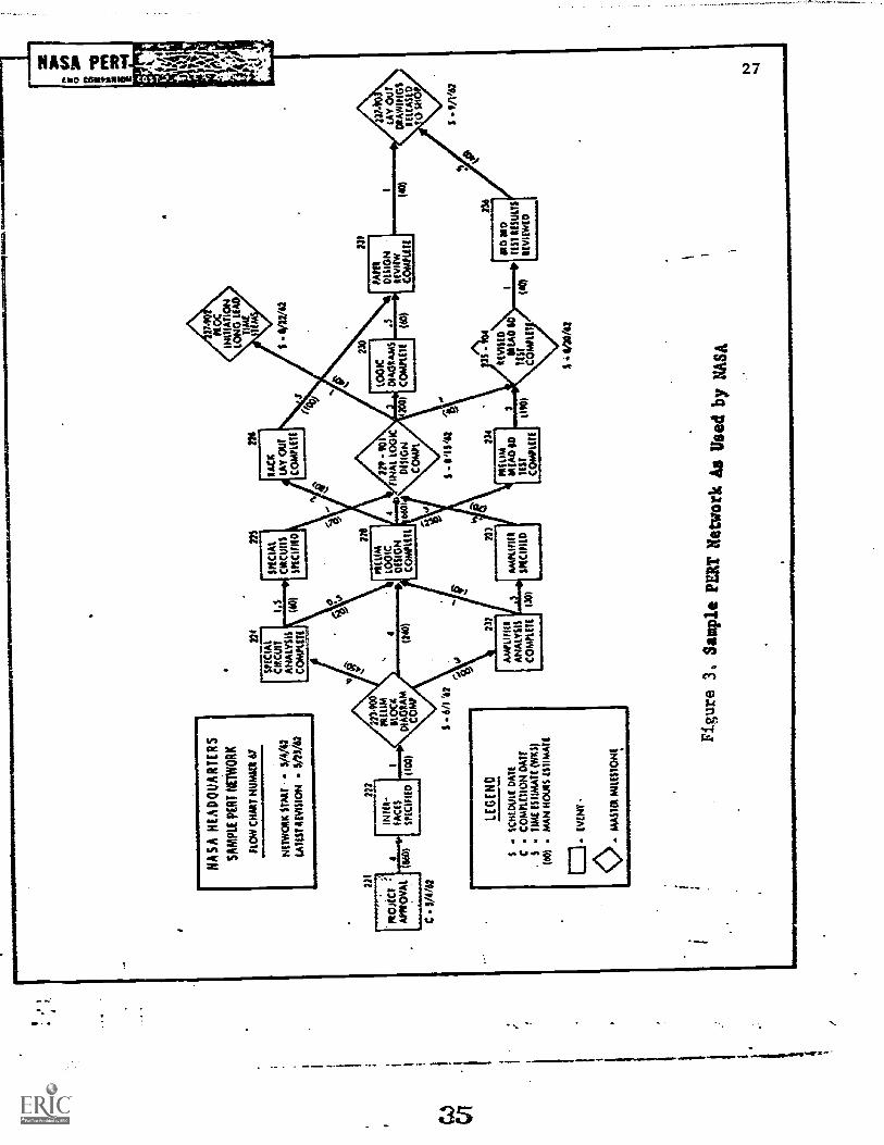
Figure 3 shows an example of a PERT Network utilized by the National-
Aeronautics and Space Administration to model those activities necessary to
complete layout drawings for a specific project.
The term PERT refers to Procrram Evaluation and Review Technique --
which is essentially a management tedhnique employing a graphic model
as a means of relating activities. PERT, as most often described has been
widely utilized In government, business and industry, and educational
settings.
Basically, the technique consists of a series of events represented by
circles Which are joined by lines representing activities. The completion
of a given activity represented by a line will result in the following
event. Activities consume time and resources (man/hours and money) while
events on the other hand consume no time or resources.
Use of PERT as a management technique necessitates the establishment
of clear objectives which in time can be translated Into events and major
events (often called major milestone).
The tedhnique utilized to its fullest allows the manager to /assign a
man/hour or man/day value to eadh Activity through the nse of the following
syMbols: a = optimistic time; b = pessimistic time; m = most likely time.
34
I
inep
usw
arso
nlm
oom
mum
414
7111
0101
11~
~1=
101.
1.1.
01N
AS
A H
EA
DQ
UA
RT
ER
S
SA
MP
LE P
ER
T N
ET
WO
RK
FLO
N C
HA
AT
NU
MM
I A/
NE
TW
OR
K S
T-P
AT
- 5/
4/62
LAT
ES
T R
EV
ISIO
N -
5/2
5/62
HI
moA
afA
mom
040
)
C5/
4/62
777
mitt
-P
AC
ES
SP
EC
IFIE
D
234
7oRar
CISCUIT
AN
ALY
SIS
CO
MP
UT
E
ns
SP
EC
IAL
ME
AT
SR
AC
K
TA
Y O
UT
coM
PLE
TE
-
4
1100
1
6/1
'62
LEG
EN
D
SC
HLD
uEI D
AT
EC
CO
mP
UT
ION
DA
TE
ST
IME
ISIIM
AT
E (
WK
S)
(SA
)m
AN
HM
S E
ST
ImA
TE
C3
EV
EN
T
- M
AS
TE
R M
ILE
ST
ON
E.
220
60 I
SIN
AI L
OG
1CD
ES
IGN
CO
MA
.111
1S/6
2
LOG
ICD
IAG
Ram
sC
OM
PU
TE
231
PA
PE
%
DE
SIG
NR
EV
IEW
CO
MP
UT
E(0
)
SP
/V63
7"A
FA
PLI
FIE
R
AN
ALY
SIS
CO
MP
LET
E
Am
puF
1111
SP
EC
IFIE
D
234
*Sum
ME
AD
60
US
TC
OM
PLE
TE
ant3
4
TE
ST
t
RE
VIS
ED
CO
MM
,o
236
MD
aus
TM
RE
SU
LTS
RE
VID
YE
D
S6/
70/6
2
Figure 3. Sample PERTNetwork As Usedby NASA
t.)
28
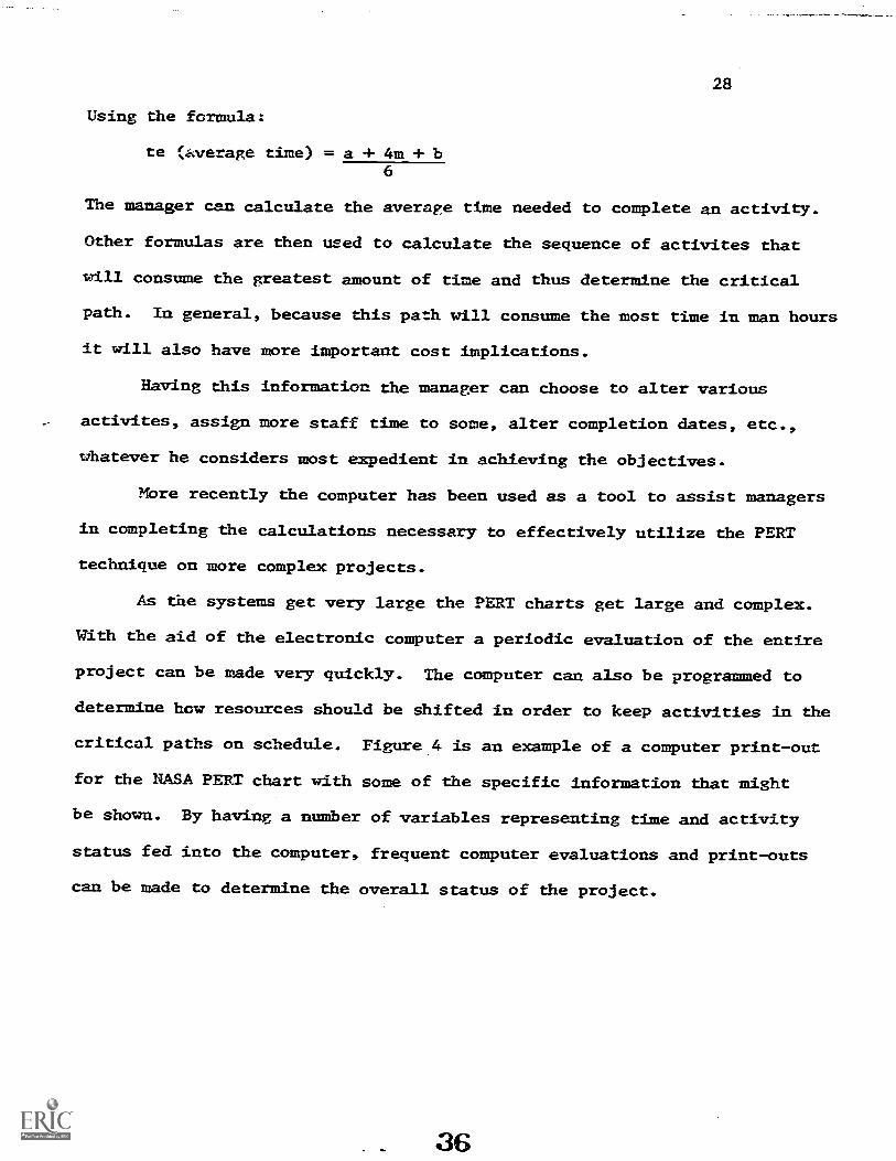
Using the formula:
te (average time) = a + 4m + b6
The manager can calculate the average time needed to complete an activity.
Other formulas are then used to calculate the sequence of activites that
will consume the greatest amount of time and thus determine the critical
path. In general, because this path will consume the most time in man hours
it will also have more important cost implications.
Having this information the manager can choose to alter various
activites, assign more staff time to some, alter completion dates, etc.,
whatever he considers most expedient in achlevIng the objectives.
More recently the computer has been used as a tool to assist managers
in completing the calculations necessary to effectively utilize the PERT
technique on more complex projects.
As the systems get very large the PERT charts get large and complex.
With the aid of the electronic computer a periodic evaluation of the entire
project can be made very quickly. The computer can also be programmed to
determine how resources should be shifted in order to keep acttvities la the
critical paths on schedule. Figure 4 is an example of a computer print-out
for the NASA PERT chart with some of the specific information that might
be shown. By having a number of variables representing time and activity
status fed into the computer, frequent computer evaluations and print-outs
can be made to determine the overall status of the project.

1111
0LIO
LV
AII
IIII
W
NASA MT
RUN
IENDING typo
in suctIssell 114141 CUNOITO AND INICOECEASOR
114041 Immo
NEIVORA
NI0
FIAT SAROLO 41100111
F11101 RUN 006041
/MAI
at.
50C.
ACTIVITY OCS0110110%
ACTIV.
TINE
EXPECTED
DAIL OF THIS REPOT IS
DAT&
OATS
ALLOPED
UNDIACT.
0000401
0000481
PROJECT APPR5VAL.
3401448
4011.4441
0000-211
0000411
DEFINING INVIMACES
4.0
64061
014848
0000.28
0000-883
FNEFARING FAE5.IOINA41 01.0C/I DIAGRAM
10
06004#
05-1942
0000-900
0000-214
POLPAnING $42CIAL cIACUII ANALYSIS
6.0
044061
003042
0000.2/4
0000424
DESIGN $1410" CIRCUITS
160
0141.61
02061
0400.228
0000420
PPLPAnt MACK LAy Our
8.0
06414#
00-21-61
0000.101
0000-22V
PREPARE LONG LUC OUNCNASt *LOOMS
1.0
004048
06-18-61
0000-22A
0000-215
1ACONP V31C (INC ANAL IA much. LOGIC 0E0
.4
4084-62
74442
0000431
0000480
INCINO APPLIFILN ANAL 14 FAWN MIC OAS
1.0
000448
4/44-41
0000-400
0000-225
pNLOANt OALLININANV LOGIC MICH
.4.9
014641
074441
0000-881
0000-829
WOW) PLC CINC OES IN FINAL LOGIC PIS
1.0
s-or-es
064142
0000228
0000-229
PNkPAnt IINAL LOGIC OttIGN
4.
064141
004148
0000433
0000-289
MORI+ AAKIFIL* DES IN FINAL LOGIC 0E0
.0
000442
00.0061
0000.901
0000-130
PAIPANt LOGIC 414411A110
3.0
001141
00-82-61
0000-2/6
0000-231
ROM RACA LAV OUT
.0
00.16411
00.10-68
41
0000-230
0900-131
UfSIGN NLVIIN OF LOGIC 0140014114
.6
094448
041048
0000-200
000C-222
PPEPANI APPLIF114 ANALYSIS
3.0
06-1061
04400
0000-232
0000-133
PLSIGA APPLIFIEM
di
000048
044648
0000-22
0000-234
PACLIP 11A24000AND It6TING
3.0
00-1468
064141
0000-236
G000./34
NLVISLO u910000450 11.411110
3.5
'
09-0061
0041-62
0000-901
0000-215
IhCONP FINAL LOGIC 00.11411 IN REA0004110
1.0
00-10-it
00.22.24
00000-004
0000-136
AVILA 4144060O0. MI 111.14_IL/
1.0
0911.64
011-39-61
0000-231
0000-211
1ACONP PLSIGN NLvIS1ONS IN LAV INOT DIGS
160
04.8141
000061
0000-2.14
0000-2)2
MOW) u.CADDOAne scvissow in LAY *UT 0400
A09-1441
604141
0000-223
0000.400
14111.101/m44 OLOtA DIAGNAPS COMPLETE
.0
0604-61
001068
06.01-61
0000-229
0000-901
fINAL LOGIC LESION COOPLIIA
.0
004148
00-01.68
00.1048
0000427
0000-501
PdOCUA 1411141164
LONO LEAD 112114
.0
004648
64841
044141
40.
0004-237
0000-903
LAI, 00 11/10,1403 AELIASED NO SHOO
.0
09.8141
09-0041
119411
0000-230
0000004
NOVIAL5 1444COOARD MT CONFLM
.0
09-0442
011.8842
064048
Figure 4. Sample of Computer Print-Out for NASA
PERT Netwoek'
1.3
,M11
01.3
1.11
0111
11.2
.111
1111
1MIM
INIS
CIN
IIIIV
rIC
IA:i
44061
110ICX
tot
Di. TIM
SOURCE *Es.04
14744
40
IA
$6$
1.0im
8.11
IO
2.0MC
1.9
100
Oa
4LLC
.9
60
11.4MC
1.1
00
I0o)
ELAC
A40
13.,
PIM
03.9
80
I.
!Let
.4
46
6.0
ELEC
A#40
660
ELCC
.et
40
10.a
L404_.
8.9
140
INS
LLCL
3.6
10
0.0
AUL
lot
106
lb.%
4LEC
NI
100
11.0
ALLt
.8.11
60
16.0
ALLL
0.4
100
0.0
ILO.
1.6
JO
4.9AM
.14
2u0
11.4
(LtC
1.9
140
14.1p
ELIA
40
13.0
itAt
1.9
40
16.0OM
40
1.0
40
MO
0LEC
1.9
40
16.0MC
1.9
01.0
LUC
tot
012.4
ELLt
40
13.0
ONIAC
.1.11
017.0
eLtt0
1.9
014.*
4L1C
.
30
A PERT chart, then, functions effectively as a communication tool, as a
logical expression of a project plan, and as a basis for project control.
These functions yield the following advantages:
1. Planning (predict)2. Reporting status3. Delegate responsibility4. Reduced complexity of large systems5. Breaks down the uncertainty areas into smaller components
Basically, then, the PERT network is used to represent time, cost, and
resource allocation. Usually, this method of modeling does not clearly
represent such aspects of the system as critical decision points,
alternative courses of action, and feedback for evaluation and redirecting
of efforts, aelm4n4qtrative relationships, material flow, etc. in the same
manner that other types of flow-chart models can do.
Another modeling technique to represent some aspect of the system is
the flow-chart model using the Logos language. The term Logos is derived
from the expression "language for optimizing graphically ordered systems."
(44:18). (For further explanation, see 44). Briefly, the Logos language
is midway between a narrative description and a strictly symbolic represen-
tation of an idea. Basic applications of Logos rely on alpha characters
forming groups of words or narratives which combined with Logos symbols
result in a flow-chart as shown in Figure 5. The narrative expressions can
be replaced by mathematical equations which are combined with the Logos
symbols to yield a flow-chart as shown in Figure 6.
The Logos language can be used to communicate effectively with
readers preferring words and also with others who prefer the more imAmbigu-
ous terminology of mathematics. Figure 7 is an example of a flowchart model
38

IDENT:FfTARGET
P0PuLATION3.1
776515597-1ivErmoas oFirNISMUCTIONI 4.2.3
I POPULATION PROPENSITY
34.1
ofANGE
OETERmINE .
AvAILA2LE & NALIFIE0TRAINEES
3.5.2
CALCuLATECOUW,E CAPACiTy
SELECTTRAI PEES
F..3.5.3
INPVICVE
COURSE EF F C 1 EUCY
TRAINEES TAKECOURSE
6.3 0
7.0 ,
GRAOUATETRAINEES
7.0
DROPOUTTRAINEES
7.0
Figure '5.. Flowchart Model of Automotive Mechanics Training System- In Operation
Brooks, Carl N. "Training System Evaluation Using MathematiealModels," Educational Technology, June, 1969.
P 4' 0 PT3.,
.A glAHPNaglAu'uPT
3.5.2
U.a4.2.3
s 'S
5.0
PAN(t)411AUCt)
3.5.1
x(t) NInCPACt), SACt)i
3.5.3
lbal6.5
7.0
Figure 6. Mathematical Niodel of
Brooks, Carl N. "Training SystemModels," Educational Technology,
39
yCtI vat-t)[1-poittO
7.0
xft-T).0Ct)
T.0
Automotive Mechanics Training.Systemin OperationEvaluation Using Mathematic:aJune, 1969.

UD
Y R
EA
L: L
IFE
EN
VIR
ON
ME
NT
=11
1=1.
1111
1.11
111.
1110
.*
CO
NS
IO1/
1 S
OC
IAL
oitio
ut IC
OK
ON
ICC
ON
SIO
CII
CU
LTU
RA
LC
ON
SIT
ION
PO
LIT
ICA
LF
AC
TO
RS
TA
5103
11?W
OO
D'
fAC
T03
$I.
I1
34
MIT
S T
O C
OIR
AT
ION
N. 0
0ALT
.N
IL03
0111
1T
.1=
1101
1111
111~
1111
1,,
CT
INM
INII
Ccl
uNtIL
NI1
1/11
1.01
0AN
C3
NO
M
toS
YS
TE
M.]I.
ULV
ilyc.
AN
ALY
ZE
PR
OB
LEM
IDE
NT
IFY
ELE
ME
NT
S
PR
OC
ES
SV
AR
IAN
. ES
Itil
lIIN
VI*
0102
TN
IkY
AM
MIS
I.I.I.
II S
UO
MI'
VA
RIA
BLE
II 1
CI 2 i
Sei
m.
11.1
TIM
MI 1
)IU
NIT t t
4 2.2
Orn
itilil
tLI
AIM
PR
OJI
Ct
iota
T.4
EV
ALU
AT
EE
LOM
NA
TE
SY
ST
EM
9S
YS
TE
M.0
MO
,
INT
RO
DU
CE
TO
TA
L S
YS
TE
M
1.1.
AM
MO
* LO
OIT
TIC
$11P
P1I
RT
T.5
1011
1111
1110
.111
1101
1.10
1111
1b
0411
14?
PC
ISO
NN
CI.
Mtn
MA
IMl
CO
ND
UC
T P
ILO
T T
ES
T
PlIC
TIS
T M
AP
LEIIC
LCC
TtA
ilPtf
110.
1
CO
NO
L.C
T
CO
AP
ISC
IINS
i/MA
NC
E
EV
ALU
AT
E
MO
ULT
S
PO
ST
ICO
T s
ums 6.
0
ICN
Ool
tS
TR
AT
IOF
FO
N
SO
LUT
ION
1111
1101
1111
111V
ES
TA
BLI
SH
PR
OJE
CT
I RE
TC
RE
IN(
LIN
ITA
TIO
NT
/4C
ON
ST
RA
INT
S
alir
0
AC
TIT
AT
II til
l P08
1
ST
AT
E P
OM
O11
041.
11
11
SIM
ULA
TE
TO
TE
ST
PR
OT
OT
YP
E
TIl
TM
OO
IL+
1.1M
i
3.0
DE
SIG
NlO
INT
irtC
OU
NS
IMJN
G/
Pla
toM
iAN
Ct
GU
IDA
NC
EC
NIT
IOIA
4.P
RO
TO
TY
PE
_5.
0(S
tE F
inn/
WI 4.
0
figur
e. 7
Cou
nsel
ing
and Guidance Program Development
System Model
Hosford, R. E. and Ryan, T. A.
"Application of Systems.Deaign In
the Development of Counseling andGuidance Programs," Unpublished
mimeographed report)
as part of readings for American Educational
!%.)
Research Association 1971 Presopsion
Systems,Rosearch for
Counseling and Educational EnVironmants.

using the Logos language as developed by Rosford and Ryan (20) representing
the development of counseling and guidance programs.
The boxes represent functions which in this case have a narrative
description and also are coded with a numeric code. This model has several
levels of specificity because the major boxes themselves have more detail
represented by boxes inside them. The detail of a model can be increased
by showing a breakdown of functions within the more major functions.
Also, note that as the detail is increased the point numeric code also
increases in digits.
Figure 8 shows additional detail of major section 4.0 in Figure 7.
The signal path represented by a straight solid line having an arrowhead
indicates the direction, origin and destination of information or material
flow. It is not within the scope of this document to give all the detail of
the language, but with this basic knowledge of the system it can be under-
stood that this modeling technique lends itself to relating parts to each
other and to the whole. As you examine the system model, you will notice
that many of the boxes act as decision points in which a decision is made
determining which alternative path the information or material will flaw.
The multiple arrows leaving a box indicate alternative courses of action
depending on current circumstances and evaluation. Also, some of the signal
paths are labeled with an "F" which indicate feedback. Feedback is based on
sone type of evaluation and information that goes back to modifying
subsequent outputs from the box to which the feedback goes.
Briefly then, the flow-chart modeling technique using the Logos
language readily lends itself to relating parts of a system to each other and
to the system as a whole. This modeling technique makes it eagy to increase
41

efea
mid
i-
90
AS
SE
SS
,R
ES
OU
RC
ES
4,1
IDE
NT
IFY
SU
BJE
CT
PO
PU
LAT
ION
4,2
PR
OC
ES
S D
AT
AF
RO
M
EN
VIR
ON
ME
NT
43
ES
TA
BLI
SH
PR
IOR
ITIE
S4,
4
0111
11M
INS
IMIN
IIIIM
MIN
Itop
.N60
wow
.
SE
LEC
T C
/G
HA
RD
WA
RK
FT
.
WA
RE
SU
PP
OR
TS
CO
ND
UC
T R
OLE
AN
ALY
SIS
AN
ALY
ZE
IMM
ED
IAT
E
BE
HA
VIO
RS
451
DE
FIN
E U
LTIM
AT
E
BE
HA
VIO
RS
452 A
R
9110
1111
0,11
11~
1811
0040
4.0~
NO
NIN
NY
IWO
MM
OR
OM
SY
NT
HE
SIZ
ER
OLE
DE
SC
RIP
TIO
N'
IDE
NT
IFY
, RE
LAT
E
CO
MB
INE
RO
L,I
ELE
ME
NT
S
TR
AN
SLA
TE
RO
LE T
O
RF
HA
VIO
RA
L O
NiC
TIV
ES

EV
ALU
AT
E 4 0
DE
SIG
N C
/G U
NIT
,
SE
QU
EN
C
$84
4-0
.4.
5
N-4-74
DEVELOP
C/G PLAN 4.0,3
AN
ALY
ZE
WE
NT
BE
HA
VIO
RS
4 0
I
84A
FL
LRN
NO
cCO
US
ELL
ING
, DE
VLO
PM
EN
TA
L
PS
YC
HO
LOG
Y 4
,81
4.8
BEHAVIORALOBJECTIVES
4.62
0111
1111
1111
1011
00sa
mM
illm
aiM
MO
OM
MO
N".
"111
1.1.
ES
TA
BLI
SH
TE
ST
ING
4 7
4
Figura 8,
Design Counseling/Guidance Program Prototype
haford, R. El and
Ryan, T. A.
"Application of Systems.Design IA
theDevelopment of Counseling and Cuidauce
rrograme," Unpublished
mimeographed report) as
part of rush') for American Educational
acccarch Associatic 1971
Presession yotems,Reelerch for
Counseling and Educational Enliironmenta.

.35
the level of specificity in the model by further identifying functions
within the box to almost endless degree of specificity. Decision points are
clearly shown along with alternative courses of action. This type of
flow-chart model, however, does not lend itself as readily to the
assignment of time, cost, and other resource allocation to individual
components.

CEAPTER III
FINDINGS AND IMYLICATIONS
Literature reviewed in the preceding chapter of this report offered
definitions of the term "system" and 'model", as well as considerations
important to the utilization of systems models as a management tool.
Summary of Findings
Based on the review of literature the following list of factors
to consider when developing systems models has been prepared-
/. The use of systems can help accomplish the following tasks:
a. Optimize outcomes
b. Organize goals and objectives
c. Identify missions and purposes
2. Some steps to be used in modeling a situation are as follows:
a. Look at the situation
b. Describe the problem in behavioral terms
c. Identify terminal goals
d. Determine what the constraints are
e. Identify subgoals
f. Establish priorities
g. Insure that all activities lead to the terminal goal
3. Four steps in using the systems technique include the following:
a. Analyze - separate and relate component parts
b. Synthesize - put parts together, related in a new way to make
a new whole
36
44

37
c. Model - represent the real world in graphic, narrative or
mathematical, etc. form
d. Simulate - test or use under conditions similar to the real
world
4. Four principles important with use of systems techniques are
included here in no particular order or priority:
a. System wholeness - the more wholeness a system bas, the more
efficient 'Ole system will be
b. Systematization - the more stren.th there is in the relation-
ship of elements, the more efficient the system will be
c. Compatibility to environment
d. Optimization - purpose of the system apreed to the objectives
5. The systems principal is not experimental; it is a method of
selecting alternatives. Goals are very broad. From goals, one
needs to relate, to restate, clarify, quantify, and define the
goals to produce objectives. From goals, one goes to objectives,
to output indicators, to criteria. As an example, a model called
SPTO (Simulation, Population, Treatment, and Outcomes) identifies
what is to be done, who is to do it, under what conditions, and
what criteria will be used to measure-
6. The steps to be followed in modeling are as follows:
a. Identify the problem in five words or less
b. State the general goals
c. Write the ideal objectives for performance, conditions, and
standards
d. Write the operational objectives for performance, conditions,
and standards
e. Check the quality of the objeetives

Im lications
The following findings and implications for the Illinois Occupational
Curriculum Project are based on the previous review of literature and
opinions offered by consultants.
1. The development of a model for the Illinois Occupational Curriculum
Project should involve the identification of factors relating to
the occupational curriculum whether within the institution or
outside the institution.and in turn relating these factors to
each other and to the curriculum system as a whole.
2. The development of a systems model for occupational curriculum
development and evaluation will necessitate that a clear definition
of purpose be prepared.
3. The Illinois Occupational Curriculum Project systems model should
be developed to include the following characteristics:
(1) organized and orderly; (2) comprised of objects, elements,
components and relationships, among components and between
components And the whole (3) function as a whole by virtue of
interdependence of its parts: (4) synthesized in an environment
to accomplish pr-.)gress toward a goal; and (5) possessed of structure,
function and development.
4. The Illinois Occupational Curriculum Project systems model should
be constructed considering general principles of systems including:
(1) The greater the deprec. of wholeness in the system, the more
efficient the system; (2) the greater the degree of systematization,
the more efficient the operation of the system; (3) the greater the
degree of compatibility between system and environment, the more
46

3'1
effective the system: (4) the greater the degree of congruence
between system synthesis and system purpose, the more effecttve
the system.
5. The Illinois Occupational Curriculum Project systems model should
consist of sufficient feedback loops for evaluation to monitor the
directiqn .of activities or re-evaluate alternatives so that
direction may be altered if needed.
6. The Illinois Occupational Curriculum Project systems model dhould
be developed through the process of anasynthesis which is the
process of analysis, synthesis, modeling and simulation. Analysis of
known systems and elements into their elements and the synthesis of
these elements into new relations making new systems.
*7. The Illinois Occupational Curriculum Project systems model must
receive its purpose, its inputs, its resources, and constraints
from the larger, or supersystem. The real measure of success of the
Illinois Occupational Curriculum Project systems model will be
measured by the degree to which it satisfies the need existing in
the larger system, thase being the educational institution utii:zing
it.
*8. The Illinois Occupational Curriculum Project systems model should
be a representation of selected factors affecting occupational
curriculum within the real world system. The systems model cannot
represent all of the aspects or factors within the real world system
but to a reasomble degree it should represent the factors that
need to be considered in developing and evaluating occupational
curriculum.

40
*9. The Illinois Occupational Curriculum Project systems modca must be
designed and developed considering the data that is available and
the data that is Teasible to obtain. The rodel cannot be data
driven (designed for readily available data) and yet the nodel can-
not be developed demanding data that cannot be obtained.
10. A criterion for evaluating the Illinois Occupational Curriculum
Project systems model should be the extent to which it represents
the real system and its resultant usefulness to curriculum planners.
11. The Illinois Occupational Curriculum Project systems model will of
necessity be complex because occupational education is a socio-
technical system including technical information along with the
human aspects. The Illinois Occupational Curriculum Project
systems model rust he developed considering the institution as a
system, the subsystems within the institutions in which it will
be utilized, and the individuals that vill work with the system.
12. After careful identification of the components thought to be
important to the system of occupational curriculum development and
evaluation and the initial development of a system model for the
same, field testing should be employed for the purpose of debugging
and validating the Illinois Occupational Curriculum Project systems
model.
13. The selection of a modeling technique should be made considering
the purpose the model will serve.
* To identify considerations related to these implications the IllinoisOccupational Curriculum Project completed a study of present practicesin decision making by curriculum planners in occupational education.(An Investigation of Decision Making Practices in Illinois JuniorColleges with Implications Toward A Systems Approach to CurriculumDevelopment and Evaluating in uccupational Education).
48

CHAPTER IV
nODELING TECOIQUI: USE]) tY ILLINOIS OCCUPATIONAL CURRICULUM PROJECT
The previ"a chapters of this report presented a basic background of
systems modeline and considerations important when utilizing systems models
for management PurPose. From these investigative activities specific
findings and tell-cations were drawn for the development of a systems model
in occupational -dneation for the Illinois Occupational Curriculum Project.
This'chapter of the report reviews the selection of the modeling technique
and the develoPOlat of the systems model by the project staff of the
Illinois OccnoSonal Curriculum Project.
As a resnit of investipative activities including: reviewing the
literature concerilizig systems, modeling techniques, application of systems
models to manaciell*nt, visitinp with personnel in the field having expertise
in the systems, alld attending a systems modeling traininp session, It was
decided that the flow chart modeling technique using Logos lanpuage would be
used by the Occupational Curriculum Project.
Recalling the definition of a systems model, a model is a representa-
tion of the real" Y'sterrl and the selection of the modeling technique for
representing the aYstem depends on the purpose and function of the model
and the system t represents. It was felt that the flow chart modeling
technique using L°gos langnage combined with narrative guidelines and
sl?ecific acti'-iCY instructions would lend itself more readily to utilization
A-1by local school a-444nistrators.
41
49

This technique allows the system to be modeled at a very general level
of specificity relating the major components and then expanding with
greater specificity within components. As the major components are
subdivided into the subsystems it is easy to expand the major components
of the model to increasing detail and relating these components to each
other and to the system as a whole. Also, using this flow'Chart mddeling
technicue made it easy to show the relationships of activities, the
decision points and the alternatives available at the decision points.
The intitial concern of the Illinois Occupational Curriculum Project is
more in being able to relate the parts to each other and to the whole
showing the activities to be completed, their relat've sequence, decision
points, and alternatives. The use of the management technique such as
pERT may be recommended as a part of implementing the systems model in a
local school setting.
The project staff developed a flaw chart model as the skeleton for
the content of the overall system of occupational curriculum development and
evaluation. Identifying the content parts or components of the system served
as the focus of two other areas of investigation carried on oy the Illinois
Occupational Curriculum Project. These investigations are reported in the
following proiect reports. 'An Investigation of Curriculum Develt,pment and
Evaluavion rodels with Impli,!ations Toward A Systems Approach to Curriculum
Development and Evaluation in Occupational Education." Unpublished
Illinois Occupational Curriculum Project report, Joliet Junior College,
Joliet, Illinois: My, 1971; and, ''An Investigation of Decision-Naking
practices la Illinois Junior Colleges with Implications Toward A Systems
Approach to Curriculum Development and Evaluation in Occupational Education."
Unpublished Illinois Occupational Curriculum Project report, Joliet Junior
College, Joliet, Illinois: Nay, 1971.
50
43
These studies served as a basis for identifyinct and relating the parts
to each other and
chart model began
components of the
to the whole system. As previously mentioned, the flow
at a low level of specificity showing only a few major
system. These components were gradually subdivided
increasing the level of specificity of the flow chart model showing more
detailed components. (A. copy of one of the initial drafts of the Illinois
Occupational Curriculum Project flaw chart model is contained in. Appendix A).
The flow chart modelinp technique appeared to also lend itself to flexibility
of use by administrators. The administrator would be free to select
alternatives according to his own situation and, if it was felt necessary,
he could even exclude sections of the model.
As this flow chart model became increasingly complex, it appeared that
the format most helpful to administrators would be to identify key questions
that would be asked at major decision points
Based on these key questions, procedures and
spelled out that would give an administrator
in the flow Chart model.
activities were carefully
assistance in obtaining objective
answers to the key question identified. To assist in executing these
specific activities sample materials and correspondence were developed to
accompany these suggested activities. In using this type of format the
administrator has the option of following the materials in a very systematic
procedure or if time and manpower does not permit the execution of all
suggested activities, the administrator may go to any particular section of
the model and obtain assistance in making decisions.
Copies of the guidelines and activities developed by the Illinois
Occupational Curriculum Project are available
updated copy of the graphic flaw chart model.
appended to this report due to their size and
31
upon request as well as an
These documents have not been
developmental state.
44
BIBLIOGRAPHY
1. Albers, Henry H. "Organizational Systems; The Decisional andInformational Processes," Principles of management - A ModernApproach. New York: John Niley & Sons, Inc., 1969.
2. Allport, G. W. "Open System In Personality Theory, Journal of
Abnormal and Social Psycholopy. 1960, 51, 301-311.
3. Arnold, Joseph. Columbus, Ohio: The Center for Vocational-TechnicalEducation, The Ohio State University- Consultation at Joliet Junior
ColleRe.
4. Banathy, BeIa D. "Systems for Education," Instructional Systems.Palo Altc: Fearon Publishers, 1968.
5. Wocker, Clyde E., et al. The Two-Year College: A Social Synthesis.Englewood Cliffs, New Jersey: Prentice-Hall, 1965.
6. Bloom, B. S. Taxonomy of Educational Oblectives - Handbook I: CognitiveDomain. New York: David McKay Co., 1956.
7. Boulding, K. A. "General Systems Theory: The Skeleton of Science",
General Systems. 1956, 1, 17.
8. Braden, Paul. School of Occupationa/ and Adult Education, College of
Education, Oklahona State University, Stillwater, Oklahoma, 74074.
Project consultant.
9. Cook, Desmond L. 216 Ramseyer Hall, 29 V% Woodruff Avenue, Columbus,
Ohio, 43210. Project consultant.
10. Cook, Desmond L. "Better Project Planning and Control Through the Use ofSystem Analysis and Management Techniques". Columbus: EducationalProgram Management Center, College of Education, The Ohio StateUniversity, November, 1967. (Mimeographed).
11. Drucker, Peter F. The Age of Discontinuity. New York: Harper and Row,1969.
12. Forrester, Jay W. "Industrial Dynamics - After the First Decade",Organization 'oncepts and Analysis, (Ed. William G. Scott).Belmont, California- Dickenson Publishing Company, Inc. 1968.
13. George, Claude S. (Jr.). Manapement for Business and Industry.Englewood Cliffs, New Jersey: Prentice-Hall, Inc., 1970.
14. Gross, Betram M. "The Coming General Systems Model of Social Systems."Human Relations, 20 - 4, November, 1967, 357-74.
15. Ball, A. D. & Fagen, R. E. "Definition of a System," In W. Buckley(Ed.), 'Modern Systems Research for the Behavioral Scientist. Chicago:
Adline Publishing Company., 1968.
52

45
16. Hartley, Harry J. Educational Plannin7-Programming-Budgeting: A
Systems Approach. Englewood Cliffs, New Jerse7: Prentice-Hall, 1968.
17. Havighurst, Robert J. 'Social Change and the Community College",The NCA Quarterly, 41 - 3, Winter, 1967, 241-48.
18. Heinich, Robert. Instructional Systems Technology Division, IndianaUniversity, Bloomington, Indiana. Project consultapt.
19. Heinich, R. "A System of Instructional Fanagemene:, unpublished paper;
November, 1962, as reported in Silvern, L.C. Systems Engineering ofEducation I: Evolution of Systems Thinking in Education. Los Angeles:Education and Training Consultants Co., 1968, p. 4.
20. Hosford, R. E. and Ryan, T. A. 'Application of Systems Design in theDevelopment of Counseling and Guidance Programs", (unpublished mimeo-graphed report) as part of readings for American Educational ResearchAssociation 1971 Presession Systems Research for Counseling andEducational Environments.
21. Katz, Daniel and Kahn, Robert L. The Social Psychology of Organizations.New York: John Wiley and Sons, 1966.
22. Kilbridge, Ilaurice, Robert P. O'Block, and Paul V. Teplitz. "A Con-
ceptual Framework for Urban Planning Models," Management Science.Vol. 15, No. 6, February, 1969.
23. Kraft, H. P. and Latta, Raymond F. 'Systems Engineering Techniques:Embarrassment or Opportunity for Today's Educators?" EducationalTechnology, September, 1969, p. 26.
24. Kuo-Cheng Wu. Ancient Chinese Political Theories, Shanghai: TheCommercial Press, Ltd., 1928, pp. 40-41,1,as reported in George,Claude S. (Jr.). 'The Managerial System's Management for BusIness
and Industry. Englewood Cliffs, New Jersey: Prentice-Hall, Inc.,1970, p.
25. Lawrence, Paul R. and Lorsch, Jay W. Organization and Environment:Nanaging Differentiation and Integration. Boston: Harvard, 1967.
26. McGregor, Douglas. "The Manager's View of the Organization", TheProfessional Manager, (Ed. Caroline McGregor and Warren G. Bennis.)
MCGraw-Hill Book Company, 1967.
27. T1cKee, Robert L. and Ripley, Kathryn Jane. "The Documentation ofSteps to Establish A Technical College ane the Evaluation of 'PERT'
As A Planning Tool for Educators, Phase I" Bailey's Crossroads,Virginia: Northern Virginia Technical College, March 31,-1966.
28. McKenney, James L. 'Critique of 'Verification of Computer SimulationModels", Management Science. Vol. 14, No. 2, Oct., 1967.
29. Miller, - J. and Rice, A. J. Systems of Organization: The Control of
Task and Sentient Boundaries. London: Tavistock, 1967.
53

30. National Aeronautics and Space Administration, Pert and ComparisonCost System, NPC 101, October 30, 1962, published by the Director ofManagement Reports, National Aeronautics and Space Administration,Washington 25, D. C.
31. Ryan, T. Antoinette. "Systems Techniques for Programs of Counselingand Counselor Education", Educational Technology. June, 1969, p. 8.
32. Roueche, John E. and BoEgs, John R. Junior College IngtitutionalResearch: The State of the Art. Washington: American Association ofJunior 0,11eges, 1968.
33. Seiler, John A. Systems Analysis In Organizational Behavior. Homewood,Illinois: Irwin-Dcrsey, 1967.
34. Sharkansky, Ira. Public Administration: Policy Making. in GovernmentAgencies. Chicago: Markham, 1970.
35. Silvern, Leonard C. President of Education and Training ConsultantsCo., 12121 Wilshire Boulevard, Lns Angeles, California, 90025.Project consultant.
36. Silvern, L. C. Systems Engineerinr of Education I: Evolution ofSystems Thinking in Education. Los Angeles: Education and TrainingConsultants Co., 1968.
37. Stern, Jacob. University of Illinois, 343 Educational Building,Urbana, Illinois, 61801. Consultation at Joliet Junior Coller....!
38. Stowe, Richard. Audio-Visual Center, Indiana University, Bloomington,Indiana, 47401. Project consultant.
39. Terreberry, Shirley. "The Evolution of Organizational Environments."Administrative Science Quarterly. 12-4, March:, 1968, 590-613.
40. Von Bertalanffy, L. "General Systems Theory", General Systems. 1956, 1, 1.
41. Von Bertalanffy, L. "General Systems Theory", General Systems. 1962,7, 1-12.
42. Wallhaus, R.'1anagement",The State ofKatzenmeyer)
A. "Modeling for Higher Education Administration andrana?ement Information Systems In Higher Education:
the Art, (Ed. Charles B. Johnson and William G.. Durham, North Carolina: Duke University Press, 1969.
43. Wiener, Norbert. Cybernetics or Control and Communication in the Animaland the Machine. Cambridge, Massachusetts: The Massachusetts Instituteof Technology Press, 1948, p. 11.
44. Silvern, L.C. "Logos: A System Language for Flowchart .74odeling",Educational Technology. June, 1969.ts.7
54

APPENDIX A
Initial rraft of Flow Chart Model for OccupationalCurriculum Identification Development,
Implementation and Evaluation
Developed by theIllinois Occupational Curriculum Project

Dr.-11.01, OX InTNTIFT !I*311:N. OT 17:1:I=103I WTI: E /:::arrn 1,4%4. nua:0-: CALk
=FA-TILT =I COTMUCTCOMI.131111:5114POLICIL5 .CcO
DIRECTIVLS am.=in3111111
1.1 1 1.1.2
I
ii
Jr
=Mu= OWOR COZZC1XWalt ADM=C10:21/17=
1.1..
1 1
=arummusx.o3 orLOCALISSTITLTIOX
1.2
OLTIJCIMECOVX3M7SCLAT1033STRATEGY
1.3
ESTIELISIISLUM=SCZ CL"13=11T=ATI= /
ACMT ..11 D3 I I' ST.FX1/-7C ImtC,..01 SUCV:571011.1Z/Cir:ATE M./..1 ATIOC: 1071rOSAL
1(ixr;t:r
1
IITC:ICU 03-COLIC PILOGRACt
2.1-42-2
ISTIL311511C0004.1.13TCOITAL=
1
f 1.o
2.0
56

COVLINIMSNI220CMANSJOS GOOFS24214
4.1.2.1.2
11 A .
-1=Zr. akr1aSICALIIIMIUSIUSCUM2asaagioamsrr g.1/ it rtttkvn$t c S":"%TECT Pea
I1-31:TAC:7j1tV.0
1111
1I PUILIC UTILITIES
TIONAND TRANSFORIA-
GOVERNMENTLOCAL, STATE4 FEDERAL
FINANCE-INS.NEAL CRATE
SOY=
Dzinactsisc22YZ WAXPOIOXAST
4 1
Oral= WCALMANFWER MUDDDATA
4.1.1
ANAIXIOLSEFFLTDow.DATA
4.1.4
NEEDmoan=4.1.
Dca=3,:=ySTNATECT FOR CAXXERINO 14=4
PDS= INSTITVTIONS. ARIASMOLA. JENIONAND CONNISFUTCONAZCE
1PRIVAIZINS122UTIONS
4.1.2.1.2
.
'INSOSTSI JOSPRONOUNS=IONSMLA=
4.1.2.1.4
4.1.2.1
cairnsLoos Jun-pow" SOITLTDATA
2 24.1.2
ztzoom nocata.4ESTARLISSADVISOSTCOMMITTEEcnocatalo
4.4.1,
DERMA* JOSDESCRISTION
X to 4.4.2
OBTAIN ANLINFORMATION(SPECIFICPIOGRAMa
4.4
tple01:ICKEIZGX4X
?X1O2ITLIM PDXIXSTITVITOX
4.1
IZT=M713:1 ioa 2X0.X.11
WAWA= NEM
or

1,.....=1:!P;:::,F.iituji,s_l_a=u:azmaslicr
IS-24TIFY COMMUNITF :OCTAL,P1LITICAL, ECONOMIC AND TECHNIC*,
*
--.OICTURE; IDEALOCICALTRLIEDS;p RELICICUS VALZES TRADITIO -
P HISTORICAL BACHCrIOUND NS*kl
; 4.2.1
1 ---.IGATHER LOCAL=sus DATA,SCHOOL RECORDS
IIDENTIFY, DEFINE AND DESCRIBETARGET POPULATION; EXPERIENCEATTITUDES, STUDY HABITS ANDCONDITIONS. LEVEL OF ACHIEVIDIENT,HIM43GENEITY, NOBILITY
4.2.2
I/DENTIFY UNIO..L,,PROFESSIONALORGANIZATIONSPOLITICALPRESSURE 4.24
DETERMINECOMMETIXTINTERESTS
4.2.5
4 2 . 3
OBTAINADDITIONALINFORMATION(srEcIncPPDGRAM) 4.7
ETERNZICE PUSLI."-z /err rri_S c-rirAr
INITIATEcorraternylezzArtoussTRATEGT
4.8.1
ATA
DETERMLNENEED FORcommarrRELATIONSEFFORTS 4.73.2
P.,ALUATE APPL ICAISILITT TO
--.De=?Eimparr
1 4.5_2
EVALUATE COMMU-
AND isiArm:ti msTrigNIT!
(ADVISJIVR.V()pm! 4.5.3
11110
DECIDE TO rurraEVALUATE PPRCPOSAL
P REPARE ANDSUBMIT FORM(7)TO TJGB
SECUREADDITIONALINFORMATIONAND AMEND
6.1.3
SECURE RESPONSEFRMK LICB
6 .1 .2
6.1
58

1
VKCIFY AND A2PLY RESOLTCE. CRITERIA
IDETEPMINE AVAILABILITY OF NF,:wED RESOURCES
1DELINEATEROLE/TASKS
2
zocarrt CONTENT
SKILLS
IALTITUDESelOWLEDGE
5.2.2
DETERMINE DECOF SANCIESS
OBTAIN COURSEOUTI.INES
IDEVT1?f=MAR =-GOING COURSES
5.2.4 5.2.5 5.2.6
IDENTIFY ON-GOING COURSESSUITABLE ORADAPTABLE(SPACE 6 up.
DETERMINEADDISION/J.NESROUCESNEEDED
DEVELOP COURSEOCTLINES ANDOBJECTIVESN20 5.2.3
DETERMINERESOURCESNEEDED
5:2.7
nermanAVAILABILITYOF RESOURCES
REVIEWALLOCATIONAND PRIORITIOF RESOURCES
S _1 ti
INITIAL INTZSTIGATION
REVIEWINSTITUTIONALRESOURCES
DETERKINEINSTITUTIONALwalurr
117-1L
5.1
OBTAININSTITUTIONALCOMM=TO PROGRAM
5.3
59

.411111!MMI
4.2
Dl

DETELor imocnAm
IDLYTirt BASICCoNCEPTS ANDCoNFETENCIES
IDENTIFYTECKNTLOGICALADVANCES
7.2 7.3
IDENTIFYOCCUFATIONALCoNFETINCYTRENDS
7.4
IDENTIFYisTCH0L0GICALQUALIFICATIONSANT ATTiTUDES
7.7
ID=TIFTENvI.R0:00XNTJJ.
FACTORS
IDEETIFTADDITIosALiNSTRuCTIoNALDIELS
ORGAN= ANDsEQuEsCE(vinyl-NE=3(LATERAL ANDLINEAR)
JPX.DEFINE AND/OROBTAINAADDITIONALTARGET POPULATIOINFoiLmATION 7,1s
sECGREENFERTT.sE
7.1
7.1
ROTIMSECHANCES
PREDICT
DEMO,BERAvioRALOBJECTIVES FORLEANN= =Ts
7.10
Enna=
OBJECTIVEREsouRcEs PZL
t s
.-1110
iDEATIFY.OMAN= ANDSEQUENCEMica=laFERTE=737.11
I
=minTEAM=TLEms.1QuEs ANDKEN* 7.12
61
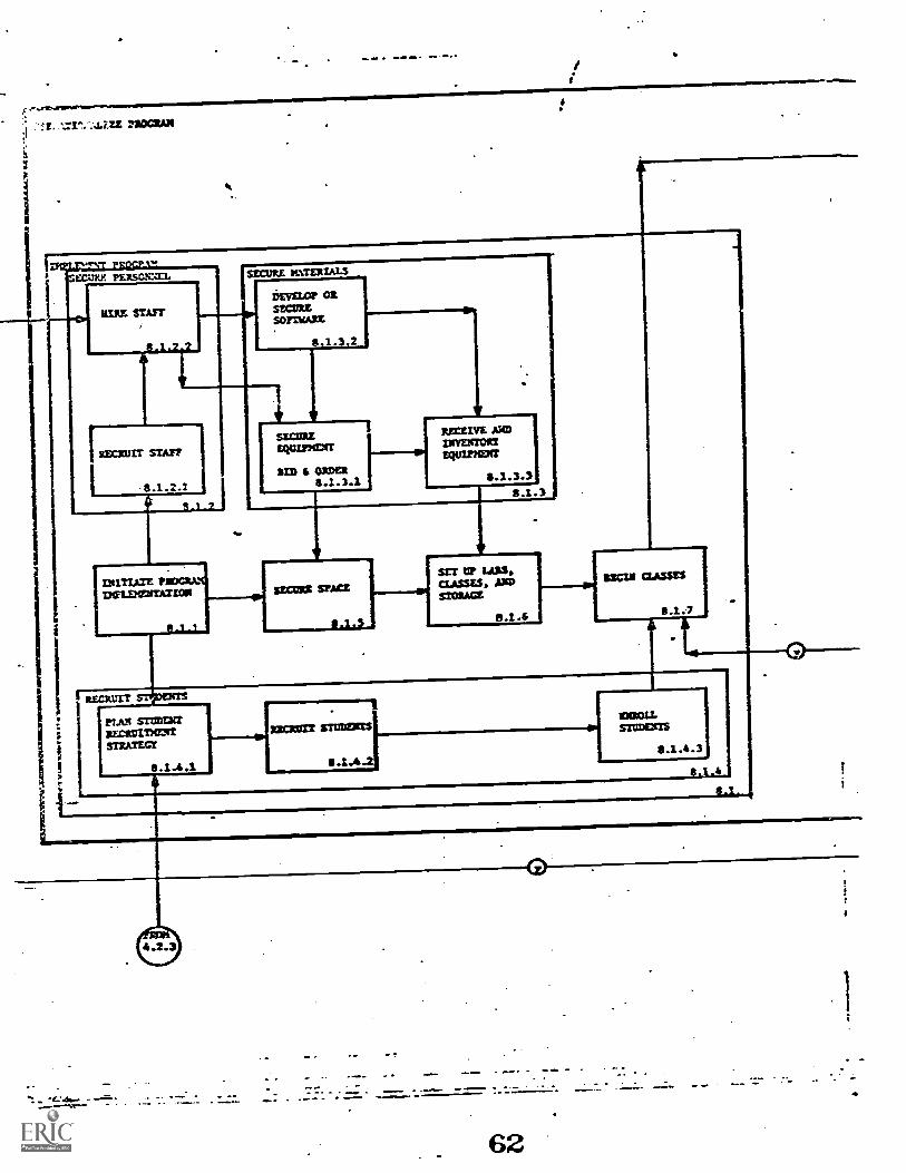
: -Ain maws. SS SO Nab 40 /a .1 S
SC.CJV.Y. PERSOMMI.
EIRE STAFF
8 .1. 2
SECURE MATER/ALS
iEVELOP=metSOFTWARE
RECRUIT STAFF
8 12
DIITIATE PROGRAN.,DWEENERTATION r-
8 - 1
8,1.3,2
SECIIREEQUIPXCIT
BED 1 ORDER3.1.3.1
RECEIVE MD13IVEITIORTRum=
1.2.3.1
3.1.3
SEMIS SPACE
SET 12" 14128.CLASSES, £10311:WAGE
8 .1 .6
WU= =Assn
RECRUIT
met snmcbrrRIX:RUTDCMITSTRATEGT
RIEZUrt STOOD=
.1.4
szczaurrs
.1.4 . 3
3.1.4 1
8.1
~Ws

nem= tvg.utrzos MAT=01111000:112MT&=AMU=321:612""12111111.2.1
007:LULZEVAL0A11.00111A1=1
1.2.2
0131:10CEM10 lit VIZ:
1111.2.3
BM? SZCOI0S
1.2.4
ISSE100X11IZCZCLiSCI=CUI
4°11211.1"'
!TALOA==En700C1ESS
$.2.1
1
POLLOir yr=DOMCONIPITEXCiI
II
* ?
8.0
63
BIBLIOGRAPHY OF ILLINOIS OCCUPATIONAL CURRICULUmPROJECT DOCU'IENTS
1. "Proposal !or Phase I of A Research and Development Project inOccupational Education: The Development of Ptocess Model: forDecision-Making in Curriculum Development and Evaluation."IOCP, Joliet Junior College, Joliet, Illinois: February 1, 1979.
2. 'Proposal for Phase II of A Research and Development Project inOccupational Education: The Development of Process Yodels forDecision-vaking in Curriculum Development and Evaluation."IOCP, Joliet Junior Collepe, Joliet, Illinois: Nay 29, 1970.
3. "Proposal for Phase III of A Research and Development Project inOccupational Education: The Development of Systems Models forDecision--7aking in Occupational Curriculum Development andEvaluation.- IOGP, Joliet Junior Colleve, Joliet, Illinois:April 23, 1971.
4. 'Phase I Report of A Research and Development Project inOccupational Education: The Development of Process ;Y!odels for
Pecisicn-Making in Curricu/um Development and Evaluation.'Unpublished report by IOCP, Joliet Junior College, Joliet,Illinois: October, 1970.
5. 'Phase II Report of A Research and Development Project inOccupational Education: The Development of Systems Modelsfor Decision-I-raking in Occupational Curriculum Development and
Evaluation." Unpublished report by IOCP, Joliet Junior College,Joliet, Illinois: T'av, 1971.
6. "An Investigation of Curriculum Development and Evaluation rodelswith Implications Toward A Systems Approach to CurriculumDevelopment and Evaluation in nccupational Education."Unpublished IOCP report, Joliet Junior College, Joli,t,Illinois: May, 1971.
7. "An Investigation of Decision--aking Practices in Illinois JuniorColleges with Implications Toward P Systems Approach toCurriculum Development and Evaluation in Occupational Education."Unpublished IOCP report, Joliet Junior College, Joliet, Illinois:May, 1971.

8. *Am Investipation of Systems nesipns and Yanagement Techniques
with Implications Toward A Systems Approach to Curriculum
Development and Evaluation in Occupational Education."
Unpublished InCP report, Joliet Junior Colleve, Joliet,
Illinois: vay, 1971.
9. 'Guidelines for Occupational Program Identification, Development,
Implementation, and Evaluation.- One unpublished ZOCP report)
Joliet Junior Colleve, Joliet, /11inois. June, 1971.
10. "Activity Manuals for Occupational Program Identification,
Development, Implementation and Evaluation." (Four unpublished
InCP reports), Joliet Junior Collepe, Joliet, Illinois: June, 1971.