document resume ef 002 043 - eric · document resume. ed 023 272. ef 002 043. specifications and...
TRANSCRIPT

DOCUMENT RESUME
ED 023 272EF 002 043
Specifications and Construction Methods for Asphalt Concrete and Other Plant -Mix Types, 3rd Edition.
Asphalt Inst., College Park , Md.Report No -SS -1Pub Date Jun 64Note -124p.Available from -The Asphalt Institute, Asphalt Institute Building, College Park, Maryland.
EDRS Price MF -$OSO HC 4630Descriptors -*Asphalts, *Buildinip Materials, *Construction (Process), *Specifications
The purpose of this publication is to assist engineers in the analysis, design and
control of paving projects that use asphalt concrete and other asphalt plant-mixes.
The scope of this new third edition has been enlarged, and changes necessitated by
advances in asphalt technology have been incorporated. Chapters I and II andAppendices A and B present information that is designed to help the engineer analyze
an asphalt paving project and prepare the project's engineering report. Chapter III is
intended as a guide to the preparation of materials and construction specifications in
accordance with decisions based on the recommendations of the engineering report.
Tables and graphs are used to support specifications and construction methods. (RK)
Specifications and Constructiim
Methods
forAsphalt Concrete
AND
OTHER PLANT-MIX TYPES
THE ASPHALT INSTITUTE
THIRD EDITWN JUNE I
eatiOri Sries.No. 1 (SS4)

U.S. DEPARTMENT OF HEALTH, EDUCATION & WELFARE
OFFICE OF EDUCATION
THIS DOCUMENT HIS SEEN REPRODUCED EXACTLY AS RECEIVED FROM THE
PERSON OR ORGANIZATION ORIGINATING IT. POINTS OF VIEW OR OPINIONS
STATED DO NOT NECESSARILY REPRESENT OFFICIAL OFFICE OF EDUCATION
POSITION OR POLICY.
Specifications and Construction
Methods
for
Asphalt Concreteand
Other Plant-Mix Types
,

Specifications and ConstructionMethods
for
Asphalt ConcreteAND
OTHER PLANT-MIX TYPES
John E. Boring, P.E.District Engineer
The Asphalt Institute4333 Nakoma Road
Madison, Wisconsin 53711
THE ASPHALT INSTITUTE
THIRD EDMON JUNE 1954
Specification Series No. 1 (SS-1)
/

FOREWORDThe purpose of this publication is to assist engineers in
the analysis, design and control of paving projects thatuse asphalt concrete and other asphalt plant-mixes. Thescope of this new third edition, has been enlarged andchanges necessitated by advances in asphalt technologyhave been incorporated.
Chapters I and II and Appendices A and B presentinformation that is designed to help the engineer analyzean asphalt paving project and prepare the project's engi-neering report. Chapter III is intended as a guide to thepreparation of materials and construction specificationsin accordance with decisions based on the recommenda-tions of the engineering report.
Other Asphalt Institute publications have been re-ferred to in the text of this book. Information aboutthem may be obtained from any of the engineering of-fices of the Institute listed in the back pages. The menwho staff these offices will welcome the opportunity toserve you.
The Asphalt InstituteAsphalt Institute BuildingCollege Park, MarylandJune 1964
v

CONTENTS
Chapter
ForewordPage
v
I. Introduction 1
1.01 Purpose ad Scope 11.02 Plant-Mix Types 1
1.03 Classification of Asphalt Paving Mixes 21.04 Control of Asphalt Application Tem-
peratures 5
II. Procedures for Developing Specifications . . . 82.01 General 82.02 General 92.03 Thickness Design 92.04 Comparison of Aggregate Gradation . 112.05 Designation of Asphalt Grade, Con-
tent 112.06 Mix Design Method 162.07 Composition of Mixes 16
III. Construction Specifications for Asphalt Con-crete and Other Plant-Mix Types ..... .. . 30
3.01 General 303.02 Mix Numbers and Thickness 313.03 Prime and Tack Coat 313.04 Approval of Materials 323.05 Asphalt 333.06 Coarse Aggregate 333.07 Fine Aggregate 353.08 Mineral Filler 353.09 Sampling and Testing Aggregate . . . . 363.10 Sand Equivalent of Combined Mineral
Aggregate . 363.11 Asphalt Paving Mixes 373.12 GenerR1 Requirements 373.13 Special Requirements 383.14 General Equipment Requirements . . . 393.15 Asphalt Mixing Plants 393.16 Requirements for All Plants 39
vii

l
Chapter Page
3.17 Spe *al Requirements for Batch TypeF nts 43
3.18 Special Requirements for ContinuousMixing Plants 46
3.19 Pavers and Laydown Machines 48
3.20 Rollers 493.21 Distributors 503.22 Haul Trucks 51
3.23 Truck Scales 51
3.24 Field Testing Laboratory 52
3.25 Hand Tools 52
3.26 General Provisions 52
3.27 Job-Mix Formula 53
3.28 Sampling and Testing 53
3.29 Weather Limitations 54
3.30 Preparation of Area to be Paved . . . 54
3.31 Preparation of Paving Asphalt 55
3.32 Preparation and Handling of Aggre-gates 55
3.33 Proportioning and Mixing 57
3.34 Control of Mixing Time 57
3.35 Transportation of Mix 58
3.36 Spreading and Finishing 58
3.37 Compaction 61
3.38 Density and Surface Requirements . 673.39 Method of Measurement 68
3.40 Basis of Payment 69
Appendices
A. Plant-Mix Pavements Using Liquid Asphalts 73
A.01 Purpose and Scope 73
A.02 General Procedures 73
A.03 Mix Design Procedures 75
A.04 Mixing and Paving Procedures . . . 76A.05 Special Test Procedures 76
A.06 Plant-Mix, Cold-Laid Paving Mix-tures Using Liquid Asphalts . . . . 77
I
ChapterPage
A.07 Plant-Mix, Hot-Laid Paving Mix-
tures Using Liquid Asphalts . . . . 78
A.08 Plant-Mix, Cold-Laid Paving Mix-
tures Using a Paving GradeAsphalt Cement with a Liquefier 80
B. Proposal and Preliminary Engineering Re-
port for the Construction of Asphalt
Paving84
C. Tables of Possible Causes of Imperfections 92
D. Sampling Asphalt Products and Specifica-
tion Compliance94
D.01 Necessity for Strict Control Proce-
dures94
D.02 Possible Causes of Contamination ofAsphaltic Material or Samples and
Suggested Precautions95
D.03 Sampling Asphaltic Materials from
Truck Tanks99
Index103
List of Members109
List of Offices112
USTRATIONS
FigurePage
I-1 Classification of Asphalt Paving Mixes . . . . 4
1-2 Viscosity vs. Temperature for Asphalts . . . . 6
II-1 Aggregate Grading Chart 10
11-2 Relationship Between Minimum V.M.A. and
Nominal Maximum Particle Size of the
Aggregate for Compacted Dense-Graded
Paving Mixtures18
A-1 Temperature-Viscosity of Liquid Asphalts 74
ix
TABLES
Table Page
II-1 An Approximate Procedure for Transform-ing "Passing-Retained" Specification toan Equivalent "Total Percent Passing"Specification
11-2 Suggested Penetration Grades of AsphaltCement for Various Paving Uses andClimatic Conditions 14
11-3 Suitability of Laboratory Design Methods . 17
11-4 Suggested Criteria for Test Limits 19
11-5 Composition of Type I Mix (MacadamType)
11-6 Composition of Type II Mixes (OpenGraded)
11-7 Composition of Type III Mines (CoarseGraded) 22
11-8 Composition of Type IV Mixes (DenseGraded) 23
11-9 Composition of Type V Mixes (FineGraded) 24
II-10 Composition of Type VI Mixes (StoneSheet) 25
II-11 Composition of Type VII Mixes (SandSheet) 26
11-12 Composition of Type VIII Mixes (FineSheet) 27
11-13 Compilation of Mix Types 28
11-14 Composition of Skip-Graded Mixes 29
12
20
21
_
Table Page
A-1 Suggested Composition of Plant-Mix Cold-Laid Paving Mixtures Using Liquid
Asphalts 78
A-2 Suggested Composition and Use of Plant-Mix, Hot-Laid Paving Mixtures UsingLiquid Asphalt 81
A-3 Suggested Composition of Plant-Mix, Cold-Laid Paving Mixtures Using Paving GradeAsphalt Cement With a Liquefier 82
C-1 Possible Causes of Imperfections in Finished
Pavements 92
C-2 Possible Causes of Deficiencies in Plant-Mix
Paving Mixtures
xi
93
Chapter I
INTRODUCTION
1.01 PURPOSE AND SCOPE.This publication isconcerned with three major items: (1) an introduction,including a method of cl?.ssification of asphalt pavingmixes and information on the use of asphalt viscosity asa means of controlling application temperatures; (2) pro-cedures for developing specifications; and (3) construc-tion specifications for asphalt concretc and other plant-mix asphalt paving. The appendices contain informationon plant-mix pavements (including the "cold-laid mix-tures") using liquid asphalts, and certain general in-formation.
By following the procedures outlined in this manual,the engineer will be able to prepare specifications whichmay include special characteristics of physical dimen-sion, quality, and financial investment according to localrequirements and limitations. He should be constantlymindful that The Asphalt Institute specifications recom-mended herein may be modified to conform to localpractice where there is sufficient service record todemonstrate satisfactory results from these practices,and where economies may result from such modifica-tion.
Information pertaining to highway location, right-of-way, sight distance, soil analysis and geometric designis not included in the text, as most highway engineeringtextbooks deal extensively with these subjects.
The Asphalt Plant Manual, Manual Series No. 3(MS-3) and Asphalt Paving Manual, Manual Series No.8 (MS-8), The Asphalt Institute, contain additionaldetail on equipment, construction methods, and inspec-tion and control.
1.02 PLANT-MIX TYPES.(1) Plant-Mix. A mixture, produced in an asphalt
1
1

mixing plant (hence the term), which consists ofmineral aggregate uniformly coated with asphalt ce-ment or liquid asphalt. The mixture is then trans-ported to the job site, spread by a paving machine,motor grader, or other means and compacted byrollers to produce a smooth paving course.
(2) Cold-Laid Plant-Mix. A plant-mix which maybe spread and compacted at atmospheric temperature.
(3) Hot-Laid Plant-Mix. A plant-mix which mustbe spread and compacted while at an elevated temper-ature. To dry the aggregate and obtain sufficientfluidity of the asphalt (usually asphalt cement), bothmust be heated prior to mixinggiving origin to theterm "hot-mix."
(4) Asphalt Concrete. A high quality, thoroughlycontrolled hot mixture of asphalt cement and well-graded, high quality aggregate, thoroughly compactedinto a uniform dense mass. Typified by Asphalt Insti-tute Type IV Mixes (refer to Table II-8).(Additional standard usage asphalt paving terms maybe found in The Asphalt Handbook, Manual SeriesNo. 4 (MS-4), The Asphalt Institute.
.
1.03 CLASSIFICATION OF ASPHALT PAVINGMIXES.Asphalt paving mixes may be produced froma wide range of aggregate combinations, each having itsawn particular characteristics and suited to specific de-sign and construction uses. Aside from the amount andgrade of asphalt used, the principal characteristics of themix are determined, in the main, by the relativeamounts of:
(1) Coarse Aggregate (retained on No. 8 sieve) *(2) Fine Aggregate (passing No. 8 sieve)(3) Mineral Dust (passing No. 200 sieve)
The aggregate composition may vary from a coarse-
* It is recognized that various agencies use different screensizes as the point of separation between fine and coarse aggre-gate. After weighing the reasons for the several break points,The Asphalt Institute has adopted the No. 8 sieve as the separa-tion screen between fine and coarse aggregate asphalt mixes.
2
textured mix having a predominance of coarse aggre-gate to a fine-textured mix having mostly fine aggre-gate.
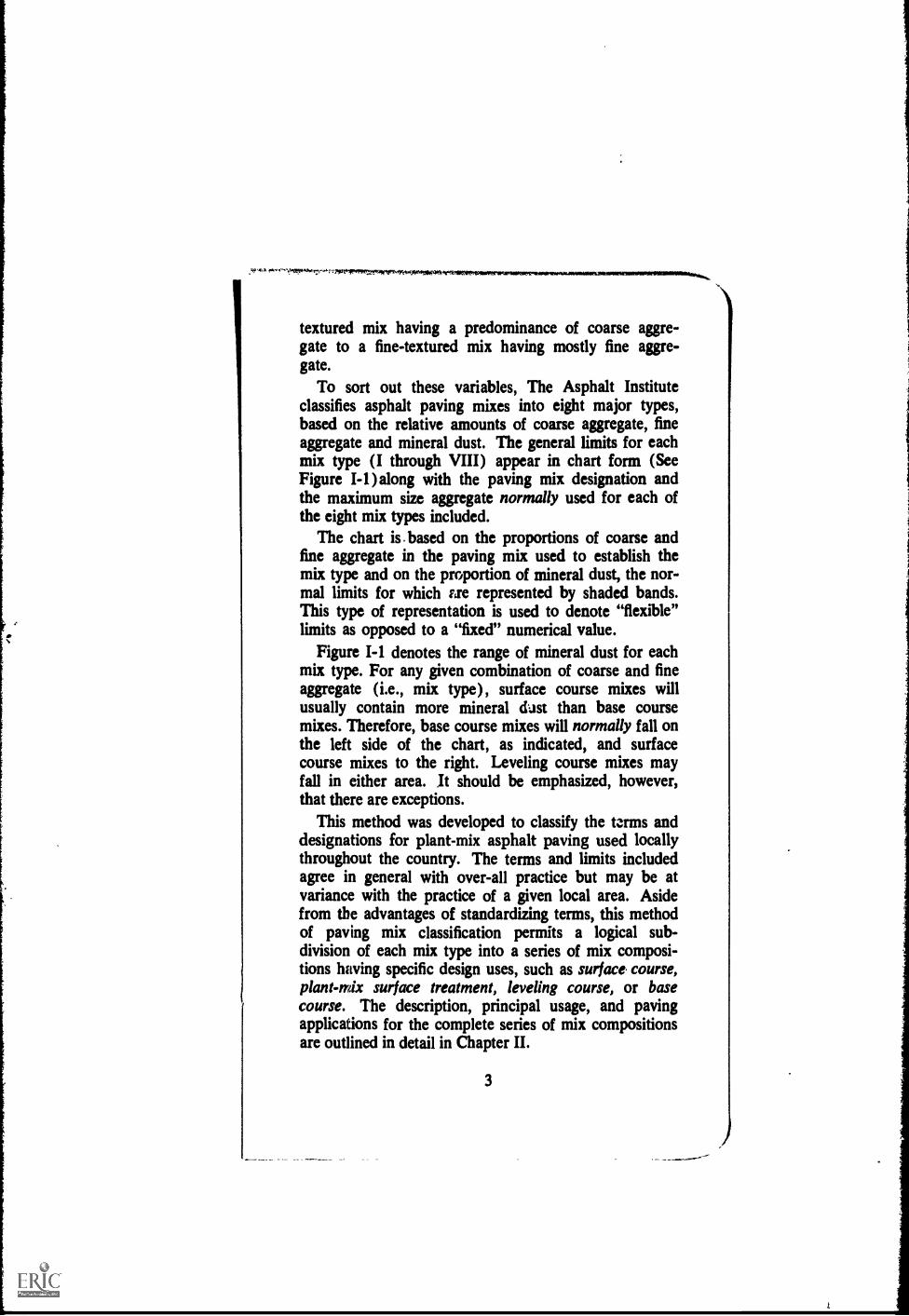
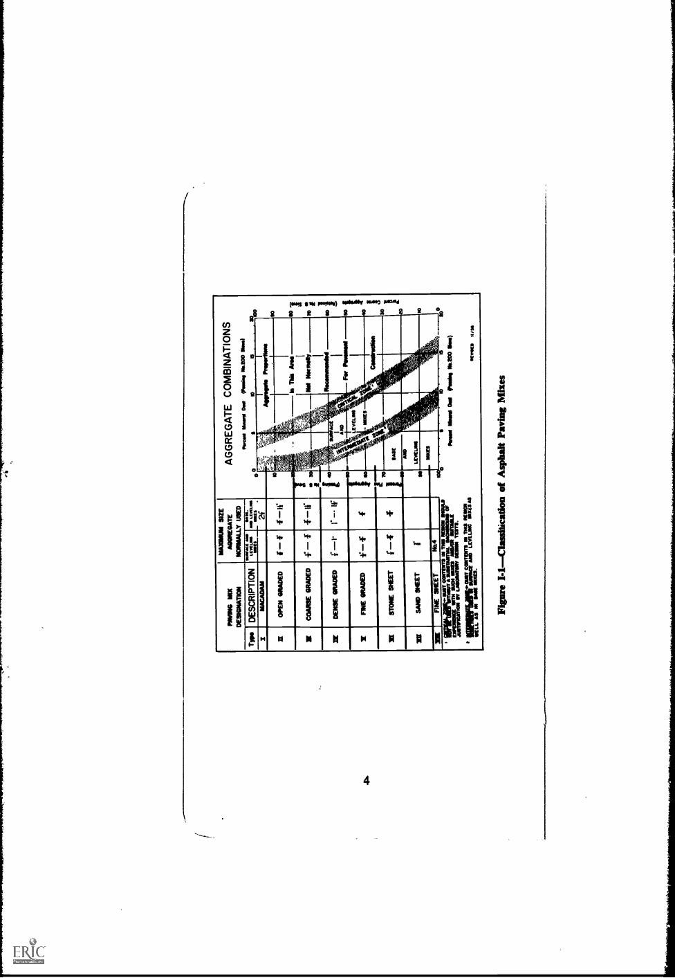
To sort out these variables, The Asphalt Instituteclassifies asphalt paving mixes into eight major types,based on the relative amounts of coarse aggregate, fineaggregate and mineral dust. The general limits for eachmix type (I through VIII) appear in chart form (SeeFigure I-I )along with the paving mix designation andthe maximum size aggregate normally used for each ofthe eight mix types included.
The chart is . based on the proportions of coarse andfine aggregate in the paving mix used to establish themix type and on the proportion of mineral dust, the nor-mal limits for which Ere represented by shaded bands.This type of representation is used to denote "flexible"limits as opposed to a "fixed" numerical value.
Figure I-I denotes the range of mineral dust for eachmix type. For any given combination of coarse and fineaggregate (i.e., mix type), surface course mixes willusually contain more mineral dast than base coursemixes. Therefore, base course mixes will normally fall onthe left side of the chart, as indicated, and surfacecourse mixes to the right. Leveling course mixes mayfall in either area. It should be emphasized, however,that there are exceptions.
This method was developed to classify the terms anddesignations for plant-mix asphalt paving used locallythroughout the country. The terms and limits includedagree in general with over-all practice but may be atvariance with the practice of a given local area. Asidefrom the advantages of standardizing terms, this methodof paving mix classification permits a logical sub-division of each mix type into a series of mix composi-tions having specific design uses, such as surface course,plant-mix surface treatment, leveling course, or basecourse. The description, principal usage, and pavingapplications for the complete series of mix compositionsare outlined in detail in Chapter II.
3
0
AG
GR
EG
AT
E C
OM
BIN
AT
ION
SA
wes
* Ill
umes
1 O
NO
PA
usin
g W
OO
Sio
n)
10
Agg
regs
m P
rope
rrie
ss
In T
his
Arm
70;
so "
FIN
E S
HE
ET
No.
4
I lip
irtan
;j1IA
TT
CO
MM
TN
1S A
MO
N M
SIA
AIL
IOT
AM
SL
SA
CS
IRO
UN
D O
Fto
m=
NU
N M
R M
CI A
MO
R S
MIL
Eju
onne
atm
V L
AS
OM
M O
ME
N T
ES
TI.
INIR
MIN
VIS
ICC
EM
AT
Z"L
EN
VE
LThR
2 11
17S
IAS
WE
LL A
S 1
16 M
E N
IXE
S.
eco
Pin
ot M
ord
Dal
poo
h, 1
116.
200
ON
O
1111
1/11
1E11
1111
11
Figu
re I
-IC
lass
ific
atio
n of
Asp
halt
Pavi
ng M
ixes

\
1.04 CONTROL OF ASPHALT APPLICATIONTEMPERATURES.Asphalt is a thermo-plastic mate-
rial that decreases in viscosity with increasing tempera-
tuie. The relationship between temperature and viscosity,
however, may not be the same for different sources ortypes and grades of asphaltic material.
Application temperatures are normally specified for
various uses of asphaltic materials but, because of these
viscosity variations, the specification of temperaturealone is inadequate for their most effective use. There-
fore, The Asphalt Institute recommends that the temper-
ature-viscosity relationship *, determined and furnished
by the asphalt producer for each asphaltic material,
must be taken into consideration to arrive at the properviscosity for the construction process being used.
The most suitable application viscosity will depend
upon such factors as:(1) Type of application(2) Characteristics and gradation of aggregate
(3) Weather conditionsBecause of these variables, the proper viscosity for a
specific application must be established by trial. The
highest viscosity (lowest temperature) should be
selected that will insure adequate coating of the aggre-
gate and proper workability for placing and compacting
the mix.Generally the most effective temperature for plant
mixing, particularly for Mix Types IV, V, VI, VII andVIII, is that which will yield viscosities in the range of150-300 centistokes (75-150 seconds Saybolt Furol).Mixing and placing of Mix Types I, II and III can often
be adequately accomplished at higher viscosities thanthose given above. In fact, it is recommended that types I
and II be mixed at viscosities of 300-1600 centistokes
(150-800 seconds Saybolt Furol) to prevent drainageof the asphalt during transit. However, no mixes should
be made at temperatures below 225°F. Current viscosity
*A chart, Asphalt Institute Form No. TV-I, is available from
the Institute for plotting these data (See Figure 1-2).
5

IIig
1100500
000
400
5011
400
300
200
150
loo
to
to
so
CO
so
40
30
25130
171
VISCOSITY VS. TEMPERATURE FOR ASPHALTS
200 223 250 273 323a
MMMMMMMMNIMIIREMIIIMNIIUMOSE
sommow MMMMM mossousemossommes MMMMM IsMMMMMMMMM smismossiumm MMMMM I- MMMMMMMMMIMIIIIIIIIMMIMMIIMMMMNIIIIII11111IllMEMEMEMEMMIIIIIIIIMOMMIIIMMINmmrninimminunion111111111MIIIIMMIMIIIIIIIIIIIIIIMUMII MIMIMIIIIIIIIIIIIIIIIIIFIUMII III1111111111111111111111111A111 III1111111112::1MililWiliiIiiiiIiiili1MIEIMMIN MiI1111.'111CMINII11IMMENIMIIM11111:11MILIIIIIII 1118 IIIIIMMEMIIIIINIIIIMMENEMM11111.:NLIIIIIIIIVICV,IIMIIIMIIMIIIMIEINIMMIMMII: 'Ruin IIIIIIMMINIMIIMINIIIIMIMIMMUILUMILIMIIIIIIIIIIII
ASPHAAT"C" wiIII MonnpwatImisoommu ismorms RASIMUMMIIII1111.1.4 la.... 1111'11.1.11A
1001-001111IN1 IMONZ1111111111111'8111111111111111111.1111.11/ laiummimegeb.^0 RI inommeoMM 1111MIllaplovernuilaMI IIMIUMMUMULI IINIIIIMIIIIIInn MINIIIIIIIIIIIIIIIIIIIOIRIIIIIIIINM 111111111111WIMMILVIIIIIMMIllMasan 1IMMIIIIMI1111111111,11111111111
IN o. JrnsrnmIonnumos,InowslaVousmoM IMMINIIIMMEMINIONIMINMINaMILMOEM IMIMME111111111MILIMINI.ENE SI 11M111111111111511111111111111111111111Mi11111111111111111111111011111111111WW111111111111111MilliM1111U= IhIIuUUhIflhIuuhULhIILflUIMUM11111111 111111111111111111VIIIIVISII11111111 11111111111111111110111101101
2MMMMM MalIMINERNIIINIU111411111=NMI= IBaMal
_MUM: NIMINIIIWOMMINSIIMIIIIIMMIIIIMBIIIIEMU.. MAIMMEMEMENIMONMEMMIIWIllum mommommunsumusinMINIM IIIIIIIMMUMMUMMIIIIIII MMM worm:
MMMMM Imo MMMMMM =RawEMINUMINE1111 ormsmossmonsmossoIINZIEMES
Pm* Nd SyINS AWNS *WV"
COMM N. WINANSNom Ns. NM
175 200 225 250 275 300
TEMPERATURE, DEGREES FAHRENHEIT
325
1300
1000
I.700
SOO
ISO
300
300
150
100
90
$o
70
10
31030
NOTE: The above chart illustrates temperature-viscosity charac-teristics for three asphalt cements, all of the 85-100 penetrationgrade.
Figure I-2Viecosity vs. Temperature for Asphalts
6

data should be available at the plant at all times to aidin determining the proper temperature of the completedbatch. Using the viscosity information, the engineershould designate the temperature of the completed mixat the plant and at the paver. Since the bulk of any mixis the aggregate, the temperature at which it is intro-duced into the mixer controls the mixing temperatures.
In the absence of suitable temperature-viscosity data,the following tabulation provides a guide for use in de-termining application temperatures:
GRADE OF Suggested MixingASPHALT CEMENT Temperature
40-50 pen 300-350*F60-70 pen 275-325°F85-100 pen 275-325°F
120-150 pen 275-325°F200-300 pen 225-275°F
7
Chapter IIPROCEDURES FOR DEVELOPING
SPECIFICATIONS
A. Engineering Survey and Analysis
2.01 GENERAL.lt is the engineer's responsibilityto make a complete survey and analysis of the specialrequirements of each plying project and to record suchinformation in an Engineering Report. This reportshould include references to methods and authoritiesused by the engineer in developing decisions.
The mak purpose of the report is to provide:(1) A record of local conditions which will in-
fluence the specifications(2) A systematic method for preparing the specifi-
cations(3) A basis for sound engineering decisions
In designing hot-mix asphalt paving, first considera-tion should be given to local conditions which may influ-ence cost and performance. The following is a list oflocal factors affecting design:
(1) SURVEY(a) Traffic(b) Climate(c) Soils(d) Aggregates(e) Asphalts(f) Available Skilled Labor(g) Available Equipment(h) Economic Factors
(2) DESIGN(a) Location(b) Drainage(c) Materials Testing(d) Thickness(e) Plans(f) Specifications
8

(3) CONSTRUCTION(a) Earth Wurk(b) Subgrade(c) Improved Subgrade(d) Subbase(e) Base(f) Asphalt Surface(g) Paved Shoulders
A suggested work form titled, "Proposal and Prelimi-nary Engineering Report for the Construction of AsphaltPaving," appears in Appendix B.
B. Preparation of Specifications
2.02 GENERALThe following information may beused by the engineer to formulate the various designfeatures which he recommends in his Engineering Re-port:
(1) Thickness Design(2) Comparison of Aggregate Gradations(3) Designation of Asphalt Grade and Content(4) Mix Design Method(5) Composition of Mixes
As he prepares his specification, the engineer shouldconstantly bar in mind that the objective of any speci-fication is to achieve a workable procedure according toestablished standards of quality and uniformity. Heshould also be alert to the economical use of materials,equipment and construction know-how.
2.03 THICKNESS DESIGN.Methods for determin-ing the thickness of surface, base and subbase are con-tained in Thickness DesignAsphalt Pavement Struc-tures for Highways and Streets, Manual Series No. 1(MS-1), The Asphalt Institute. This booklet presents indetail, procedures for traffic analysis, materials analy-sis, alternate designs, economic analysis and selectionof design, together with compaction requirements and asection listing typical examples illustrating the variousthickness design formulas.
9

1
01116111.
410104
atIO
N011
11111
4101,
16%
AG
GR
EG
AT
EG
RA
DA
TIO
NC
HA
RT
itS.
STA
MM
VM
S-
AST
IIO
ESIG
IIAT
ION
EII
os
Dia
Sae
So/
eso
asr
raas
arsw
ere
I.
so
=M
ilN
MI
i&
...AA
OM
AN
OM
=.er
a.aw
a.*e
ewe
35%
aI
aa
i0
iitor
row.
asre
ra.
so410
INN
O111111C
MU
AIM
aa
MI
40
0IN
TE
RPO
LA
TE
DV
AW
ES
moirro
VA
LU
ES
1111111111
1111101
1044111
'I
aa
11
/1/1
a.,N
Vser
OP
E111110
ININ
ES
(LOS
SC
ALE
)
......
,!
.a
111.11111111
Ponpond
NI
*MA
OM
IMI
CO
MM
PA
MO
LUIV
IAN
IPN
o.414
Figaro11-1A
ggregateG
radingC
hart

%MOM PiMallaMWommia......gr
2.04 COMPARISON OF AGGREGATE GRADA-TION.Comparison of mixes recommended by variousmanizations is often difficult because of different meth-ods of expressing aggregate gradations. There are twostandard sieve series and two methods of showing therelative proportions of the several sizes of aggregates.
The Asphalt Institute has adopted the sieve seriesusing the following square sieve opening-21/2 in., 11/2in., 1 in., in., 1/2 in., in., No. 4, No. 8, No. 16, No.30, No, 50, No. 100 and No. 200. In mixes with a lowpercentage of fine aggregate, the No. 100 sieve is con-sidered of little importance in the total gradation.
Standard aggregate charts usually show a parallelscale for each sieve series, and conversion from onesieve size to another may be made by interpolation, i.e.,by plotting the gradation and circling the points on thechart representing the desired sieve sizes. This is illus-trated in Figure 11-1.
Aggregate gradations are expressed by two methods:(1) total percent passing or, conversely, total percent re-tained method; and (2) the so-called "passing and re-tained" method wherein the percentage range passingeach sieve size and retained on the next smaller sieve isspecified.
The Asphalt Institute has adopted the "total percentpassing" method.
The "total percent passing" method is easily con-verted to "total percent retained" by subtracting from100 the figure shown for each sieve size.
Values in the "passing and retained" method may beconverted to approximately equivalent values in "totalpercent passing" method by making a tabulation andfollowing the steps indicated in Table II-1.
2.05 DESIGNATION OF ASPHALT GRADE,CONTENT.Selection of the proper grade of asphaltcement is important. The grade performing most satis-factorily on local projects of similar aggregate grada-tions and traffic conditions should receive first consider-ation. The recommendations in Table 11-2 are intended
11

TA
BL
E I
I-1A
N A
PPR
OX
IMA
TE
PR
OC
ED
UR
E F
OR
TR
AN
SFO
RM
ING
"PA
SSIN
G-R
ET
AIN
ED
" SP
EC
IFI-
CA
TIO
N T
O A
N E
QU
IVA
LE
NT
°T
OT
AL
PE
RC
EN
T P
ASS
ING
" SP
EC
IFIC
AT
ION
.
'Ass
umed
"Pa
ssin
g-R
etai
ned
Spec
ific
atio
nSt
ep 1
Step
2St
ep 3
Step
4
Las
ing
Ret
aine
dPe
rcen
tT
otal
Mat
eria
l 1
....
wev
eSi
ze
Cum
ulat
ive
Perc
ent P
assi
ng,
Fine
to C
oars
eSi
zes
Cum
ulat
ive
Perc
ent R
etai
ned
Coa
rse
to F
ine
Size
s
Cum
ulat
ive
Perc
ent P
assi
ng,
Coa
rse
to F
ine
Size
s
Equ
ival
ent
sca
tion
on "
Tot
al P
erce
ntPa
ssin
g" B
asis
°M
s.M
ax.
MU
.W
m.
Ms.
Max
.C
ol. N
o.1
Col
. No.
2C
ol. N
o.C
ol. N
o.6
CoL
No.
6C
ol. N
o.7
CoL
No.
2C
ol. N
o.I
Col
. No.
15C
ol. N
o.11
Col
. No.
Col
. No.
121$
l% h
i.1
in.
% in
.%
la-
% in
$t 4
* $
*16
* $0
* SO
* 10
0*2
20
1 53
.%
in.
% in
.%
in.
*4 * $
*16
$t $
0*1
0*1
00*2
00
513
411
512
5II
II13
1014
212
711
610
5II
4 -
12
- 7
1% in
.1
in.
% in
.%
in.
% in
.*4 *
3*1
6*
30*5
0*1
02*2
00
es 6$ $9 54 51 42 22 24 17 116 2
nai-
100+
109*
os 24 71 $7 46 $4 24 15 7
o 4 1 12 n $1 $e 46 52 57 61
12 215 a so s TT 32 1204
-le
o+12
6-1-
1004
-
100 so a a 75 65 61 54 42 4$ so
32 71 ss so 57 2$ 110 0 0 o
2210
071
N19
Ill
5124
4271
$257
244$
17S.
1124
415
27

Not
es: C
OL
UM
N 5
is th
e sa
me
as C
olum
n2
repe
ated
for
con
veni
ence
and
cla
rity
CO
LU
MN
6 is
der
ived
by
addi
ng th
e va
lues
in C
olum
n 3
from
rin
e to
Coa
rse
CO
LU
MN
7 is
der
ived
by
addi
ng th
e va
lues
in C
olum
n 4
from
rin
e to
Coa
rse
CO
LU
MN
8 is
der
ived
by
addi
ng th
e va
lues
inC
olum
n 3
from
Coa
rse
to F
ine
CO
LU
MN
9 is
der
ived
by
addi
ng th
e va
lues
in C
olum
n 4
from
Coa
rse
to F
ine
CO
LU
MN
10
is d
eriv
ed b
y su
btra
ctin
g th
e va
lues
in C
olum
n 8
from
100
(i.e
. Col
umn
10=
100-
-C
olum
n 8)
. iC
OL
UM
N 1
1 s
deri
ved
by s
ubtr
actin
g th
eva
lues
in C
olum
n 9
from
100
(i.e
. Col
umn
11=
100
Col
umn
9).
The
val
ues
for
CO
LU
MN
12
are
obta
ined
by
- A
ectin
g w
hich
ever
val
ue is
the
larg
er f
rom
eith
erC
olum
n 6
or C
olum
n 11
(i.e
. Col
umn
12=
Maz
imum
val
ue f
rom
Col
umn
6 an
d C
olum
n 11
).T
he v
alue
s fo
r C
OL
UM
N 1
3 ar
e ob
tain
ed b
y se
lect
ing
whi
chev
er v
alue
is th
e sm
alle
r fr
om e
ither
Col
umn
7 or
Col
umn
10 (
i.e. C
olum
n13
=M
inis
sum
val
ue f
rom
Col
umn
7 an
d C
ohan
='fl
Whe
re m
ore
or f
ewer
scr
een
size
s ar
e us
ed,
Col
umns
3, 4
and
5 w
ould
be
chan
ged
acco
rdin
gly.
Gen
eral
ly, r
ound
ed f
igur
es a
re u
sed
as s
peci
fica
tion
limits
in C
olum
ns 3
and
4 a
nd in
Coh
an=
12 a
nd 1
3.T
he f
igur
es u
sed
in th
is ta
ble
wer
e se
lect
ed to
indi
cate
mor
e cl
earl
y th
e m
etho
d.
*It w
ill b
e no
ted
that
a v
ery
narr
ow s
peci
fica
tion
byth
e "P
assi
ng a
nd R
etai
ned"
met
hod
give
s a
muc
hw
ider
Spec
ific
atio
n by
the
"Tot
al P
erce
nt P
assi
ng"
Met
hod.
Thi
s ab
ility
of
the
"Tot
al P
erce
nt P
assi
ng"
met
hod
to p
rovi
de a
nar
row
aos
e co
ntro
l on
the
grad
atio
n,w
ith r
easo
nabl
e m
argi
ns o
n th
e sc
reen
siz
es,
is a
n im
port
ant a
dvan
tage
of
this
met
hod.

only for the engineer's general guidance where local ex-perience does not provide an adequate basis for theselection of the proper grade of asphalt.
(1) Proportioning Asphalt. In the proportioning ofpaving mixes, it is important to note that there aretwo methods of specifying asphalt content"percentby weight of total mix" or "percent by weight of dryaggregate."
TABLE II-2SUGGESTED PENETRATION GRADES OFASPHALT CEMENT FOR VARIOUS PAVING USES AND
CLIMATIC CONDITIONSAllMB.PAVING CLIMATE
USES Hot and Temperate Cold
AirfieldsRunwaysTaxiwaysParking Aprons
60-7060-7060-70
120-15085-10085-100
HighwaysHeavy Traffic 60-70 85-100Medium to
Light Traffic 85-100 120-150
Streets
Heavy Traffic 60-70 85-100*Medium to
Light Traffic 85-100 85-100
DrivewaysIndustrial 60-70 85-100Service Station 60-70 85-100Residential 60-70 85-100
Parking LotsIndustrial 60-70 60-70Commercial 60-70 85-100
RecreationalTennis Courts 85-100 85-100Playgrounds 85-100 85-100
Curbing 60-70 85-100
* 60-70 penetration normally used for sheet asphalt (Type VIIIMixes).
14

The engineer should be alert to this distinction in thecompletion of the mix composition portion of the spec-ifications and in the comparison and review of localpractice.
If "percent by weight of total mix" is used and anasphalt content of 6.0 percent is indicated, a 100-1b.sample will contain 6 lbs. of asphalt and 94 lbs. of dryaggregate. In this case an equivalent asphalt content
6based on weight of dry aggregate is x 100 or 6.38
94percent asphalt by weight of dry aggregate.
If "percent by weight of dry aggregate" is used andan asphalt content of 6.0 percent is indicated, then 6lbs. of asphalt are combined with 100 lbs. of dry ag-gregate to produce a total mix weight of 106 lbs. Anequivalent asphalt content based on the total weight of
6mix would be x 100 or 5.66 percent by weight of
106total mix. The "percent by weight of total mix" is thepreferred method; however, either method may beused provided it is clearly understood by all personsconcerned.
(2) Asphalt Content. The range of asphalt contentshould be indicated for each of the mix compositionsselected for the specifications. This range should ordi-narily be determined in accordance with the specifiedmix design method. It is often necessary to completethe specifications before a preliminary mix designhas been made. In this case, the asphalt content nor-mally is based on the use of relatively non-absorptiveaggregates with a bulk specific gravity of 2.65. Cor-rections, as described in Mix Design Methods for As-phalt Concrete and Other Hot-Mix Types, ManualSeries No. 2 (MS-2), The Asphalt Institute, should bemade later for variations.
In case the specifications do not provide for a mixdesign method, the range of asphalt content may bedetermined directly from values shown for the mix
15

type. The range of asphalt content for each mix desig-nated should be within fairly narrow limits.
In any event, the asphalt content of the final job-mixformula can only be determined from experience orafter the asphalt plant is in regular operation and thecharacteristics of the production mix have been estab-lished on the job.2.06 MIX DESIGN METHOD.For completion of
the specifications, "Special Requirements" in Section C,Chapter III, provides for the insertion of test require-ments for the total paving mix. The completion of thisportion of the specification involves the selection of amix design method and applicable design criteria. Herethe engineer should again review local practice with re-gard to mix design and the standard mix design methodsin general use. The Asphalt Institute publication, MixDesign Methods (MS-2), sets forth detailed outlines oftest procedures for three widely used methods of hot-mix paving designthe Marshall (ASTM Designation D1559, Resistance to Plastic Flow of Bituminous MixturesUsing Marshall Apparatus), the Hubbard-Field (AASHODesignation T 169, ASTM Designation D 1138), and theHveem (ASTM Designation D 1560, Resistance to De-formation and Cohesion of Bituminous Mixtures byMeans of Hveem Apparatus, and ASTM Designation D1561, Preparation of Test Specimens of Bituminous Mix-tures by Means of California Kneading Compactor).
Table 11-3 is a guide to the suitability of a specific mixdesign method for each of the eight types of mixes.Table 11-4 lists suggested criteria for test limits applica-ble to each traffic classification.
2.07 COMPOSITION OF MIXES.The eight mixtypes (Table 11-5 through 11-12) cover the range ofmixes in general use, from macadam types throughgraded aggregate types to sand and sheet asphalt types.
Of these, the Type IV Mixes (Table 11-7) are recom-mended without qualifications for use in pavementcourses for all traffic classifications. Criteria for theiruse have been established by extensive field and labor-atory tests and are the basis for the recommended design
16
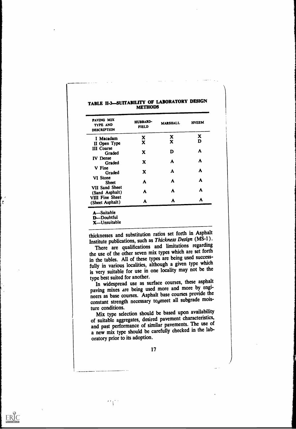
TABLE II-3SUITABILITY OF LABORATORY DESIGNMETHODS
PAVING MIXTYPE AND
DESCRIPTION
HUBBARD-FIELD
MARSHALL HVEEM
I Macadam X X X
II Open Type X X D
III CoarseGraded X D A
IV DenseGraded X A A
V FineGraded X A A
VI StoneSheet A A A
VII Sand Sheet(Sand Asphalt) A A A
VIII Fine Sheet(Sheet Asphalt) A A A
ASuitableDDoubtfulXUnsuitable
thicknesses and substitution ratios set forth in Asphalt
Institute publications, such as Thickness Design (MS-1 ).
There are qualifications and limitations regarding
the use of the other seven mix types which are set forth
in the tables. All of these types are being used success-
fully in various localities, although a given type which
is very suitable for use in one locality may not be the
type best suited for another.In widespread use as surface courses, these asphalt
paving mixes are being used more and more by engi-
neers as base courses. Asphalt base courses provide the
constant strength necessary tglianeet all subgrade mois-
ture conditions.Mix type selection should be based upon availability
of suitable aggregates, desired pavement characteristics,
and past performance of similar pavements. The use of
a new mix type should be carefully checked in the lab-
oratory prior to its adoption.
17

\
!
i
)u
40
10
20
10
_ RADS OF DIAGRAM
AWL 1111 DKRMARTI, OF MGM
ORIENT NI ONOASPIIMT
01 AR VOIDS
1
40 1 1 le Yr se 1" 11/i. 2"
NODAL NOUN PARTICI Wf-U.S. STANDARD REVS MIN OPENINGS
Figure II-2Relationship Between Minimum V.M.A. andNominal Maximum Particle Size of the Aggregate for Compacted
Dense-Graded Paving Mixtures
When mix Types I, II or III are to be laid over a plas-tic subgrade course, they should have a blanket, not lessthan two inches thick, of screenings or clean sand toprevent intrusion of the plastic material into the asphaltbase course.
(1) "Skip-Graded" Mixes. Mix Types I throughVIII are based on graded aggregates falling withinrelatively narrow grading bands. There are, however,known examples where the use of "skip-graded" aggre-gates have provided satisfactory pavements withlengthy service records.
So called "skip-graded" mixes usually are densemixes designed to develop maximum interlock of thecoarse aggregate particles and which depend largelyon this interlock for stability. To accomplish this, asand or fine aggregate of a top size that will not bulkthe coarse aggregate is normally used. The mix is soproportioned that the fine aggregate acts as a mortarfilling the voids in the coarse aggregate, but not bulk-ing it sufficiently to affect interlock.
Specification grading bands for this type of mixmust necessarily be broad. The job-mix formula set
18

TABLE II-4-SUGGESTED CRITERIA FOR TEST LIMITS*
DESIGN METHOD
HEAVY MEDIUM LIGHTTRAFFIC** Mance Tamince
Min. Max. Min. Max. Min. Max.
MarshallNumber of compac-
tion blows, eachend of specimen 75 50 35
Stability, all mixtures 750 500 500Flow, all mixtures 8 16 8 18 8 20% Air Voids
Surfacing or Level-ing 3 5 3 5 3 5
Sand or Stone Sheet 3 5 3 5 3 5Sand Asphalt 5 8 5 8 5 8Base 3 8 3 8 3 8
% Voids inMineral AggregateSurfacing or Level-
ing See Figure 11-2Sand or Stone Sheet See Figure 11-2Sand Asphalt . See Figure 11-2Base See Figure 11-2
Hnkhsrd-FleldOriginal Method
Stability, lbs. 2000 1200 2000 1200 2000% Air Voids 2 5 2 5 2 5
MemStabilometer 37 35 30Cohesiometer 50 50 50Swell, inches .03 .03 .03% Voids 4 4 4
*Criteria applicable only when testing is done in conformance withmethods outlined in Asphalt Institute publication, Mix Design Methodsfor Asphalt Concrete and Other Hot-Mix Types, Manual Series No. 2.All criteria, not stability value alone, must be considered in designingan asphalt paving mix.
"See Thickness Deegn, Asphalt Pavement Structures for Highways andStreets, Manual Series No. I for details of traffic classifications.
***Although not a routine part of the design method, an effort is madeto provide a minimum of 4% air voids.
within these bands should be adhered to in the toler-ances outlined in Section C, Chapter III.
These mixes can be placed to a very uniform tex-tured surface using machine methods, but they have atendency to segregate if hand placing is not performedskillfully. All construction and inspection proceduresmust be very closely controlled.
The three mixes noted in Table 11-14 are examplesof the "skip-graded" type.
19
I

TABLE MSCOMPOSITION OF TYPE I MIX(Macadam Type)
MIX NO.
USE
Ia
Base
COMPACTEDDEPTH
RECOMMENDEDFOR INDIVIDUAL
COURSES
3 in.-4 in.
SIEVE SIZES(SQUARE
OPENINGS)
Percent PassingBy Weight
21/2 in.
Ph in.
1 in.
in.
1/2 in.
Vs in.
# 4
# 8
# 30
# 100
# 200
100
35-70-0-15---
0-5--
0-3
Normal asphalt content 3114.5% by weight of total mix. Upperlimit may be raised when using absorptive aggregate.
Usual Applications: For all light and medium traffic classifica-tions.
Traffic Limitations: Not recommended for heavy traffic classifica-tions.
Surface Texture: Very open and porous (requires surface course.)
Aggregate Required: Sound, angular crushed stone, crushedgravel, 01 crushed slag and fine aggregate.
20

TABLE II-6COMPOSITION OF TYPE II MIXES
(Open Graded)
MIX NO. Ha lib lIc IId He
SurfacePlant-Mix Plant-MixUse Surface Surface Base Base
SurfaceTreatment Treatment
CompactedDepth
Recommended 34 in.-for Individual 44 in.
Courses
44 in.-11/2 in.
I in.-2 in. Ph in.-3 in. 3 in.-4 in.
Sieve Sizes(Square
OPenings)Percent Passing By Weight
11/2 in. 100
1 in. 100 70-100
N in. 100 70-100 50-80
1/2 in. 100 70-100 _ _h in. 100 70-100 45-75 35-60 25-50
# 4 40-85 20-40 20-40 15-35 10-30
# 8 5-20 5-20 5-20 5-20 5-20
# 30 _ _ _# 100
# 200 0-4 0-4 0-4 0-4 0-4
Normal asphalt content 3.0-6.0% by weight of total mix. Upperlimit may be raised when using absorptive aggregate.
Usual Applications: For all light and medium traffic classifica-
tions.
Traffic Limitations: Not recommended for heavy traffic classifica-
tions.
Aggrepte Required: Sound, angular crushed stone, crushedgravel, crushed slag and fine aggregate.
21

TABLE 11-700MPOSITION OF TYPE III MIXES
(Coarse Graded)
MIX NO. IIIa IIIb Ilk HId Me
Surface orUSE Surface Leveling Base Base Base
COMPACTEDDEPTH 1/2 in.-RECOMMENDED 44 in.- 1 in.-2 in. 1 in.-2 in. 1 3 ln.-4 in.
FOR INDIVIDUAL 11/2 in.
COURSES
SIEVE SIZES(SQUARE
OPENINGS)Percent Passing By Weight
11/2 in. 100
1 in. 100 75-100
44 in. 100 100 75-100 60-85
1/2 in. 100 75-100 75-100
in. 75-100 60-85 60-85 45-70 40.-65
# 4 35-55 35-55 30-50 30-50 30-50
# 8 20-35 20-35 20-35 20-35 20-35
# 30 10-22 10-22 5-20 5-20 5-20
# 50 6-16 6-16 3-12 3-12 3-12
# 100 4-12 4.12 2-8 2-8 2-8
# 200 2-8 2-8 0-4 0-4 0-4
Normal asphalt content 3.0-6.0% by weight of total mix. Upper limit mcybe raised when using absorptive aggregate.
Usual Applkatious: For light, medium and heavy traffic classifications.
Traffic Limitations: Mix Types Illa, IlIb, and IIIc are not recommestledfor heavy traffic classifications.
Surface Texture: Openmedium to coarse.
Aggregate Required: Sound, angular crushed stone, crushed gravel orcrushed slag, and fine aggregate.
22

*'"I'F4Ivrklowtirtmesei
TABLE MICOMPOSITION OF TYPE IV MIXES
(Dense Graded)
MIX NO. IVa 1Vb IVc
USE Surface SurfaceSurface
orBase
IVd
Base
COMPACTEDDEPTH
RECOMMENDED In.-FOR INDIVIDUAL 11/2 in.
COURSES
1 In.-2 In. 11/2 in.-3 in. 21/2 in.-41n.
SIEVE SIZE(SQUARE
OPENINGS)Percent Passing Ey Wellihi
11/2 in. 100
1 in. 100 80-100
in. 100 10-100 70-90
1/2 in. 100 80.-100
It in. 80-100 70-90 60-80 55-75
* 4 55-75 50-70 48-65 45-62
# 8 35-50 35-50 35-50 35-50
* 30 11-29 11-29 19-30 19-30
* 50 13-23 13-23 13-23 13-23
* 100 8-16 8-16 7-15 7-15
* 200 4-10 4-10 0-8 0-1
Normal asphalt content 3.5-7.0% by weight of total mix.be rcdsed when using absorptive aggregate.
Type IV Mixes are recommended Mr all applications; I.e. 1
Upper limit may
or asphalt pavingcourses Mr all traffic classifications.
Tranie Limitations: None.
Surface Texture: Medium to fine.
Aurepte Required: Sound, angular crushed stone, crushed gravel or crushedslag, and fine aggregate.
23

TABLE 11-9COMPOSITION OF TYPE V MIXES
(Fine Graded)
MIX NO. Va Vb
USE SurfaceSurface orLeveling *
COMPACTED DEPTHRECOMMENDED FOR
INDIVIDUAL COURSES
in.-11/2 in. 1 in.-2 in.
SIEVE SIZES(SQUARE OPENINGS) Percent Passing Ely Weight
in.
1/2 in. 100
100
85-100
1/4 in. 85-100* 4 65-80 65-80* 8 50-65 50-65* 16 37-52 37-52* 30 25-40 25-40* 50 18-30 18-30* 100 10-20 10-20* 200 3-10 3-10
Normal asphalt content 4.0 -7.5% by weight of total mix. Upperlimit may be raised when using absorptive aggregate.Usual ApplIcationrSurface: General utility mix. Often used for streets and high-
ways, driveways, parking lots, and playgrounds. Widely usedwhere coarse aggregates are scarce or expensive.Leveling: For leveling of uneven bases.
Traffic Limitations: For heavy traffic, the finer grades of the mixtype tend to be somewhat sensitive to variations in proportion-ing and may become critical. Thorough laboratory testingnecessary before being used for heavy traffic classifications.
Surface Texture: Dense and gritty.Aggregate Required: Hard, sound, angular crushed stone, crushed
gravel or crushed slag, and fine aggregate.
* May be used for base where coarse aggregate is not eco-nomically available.
24
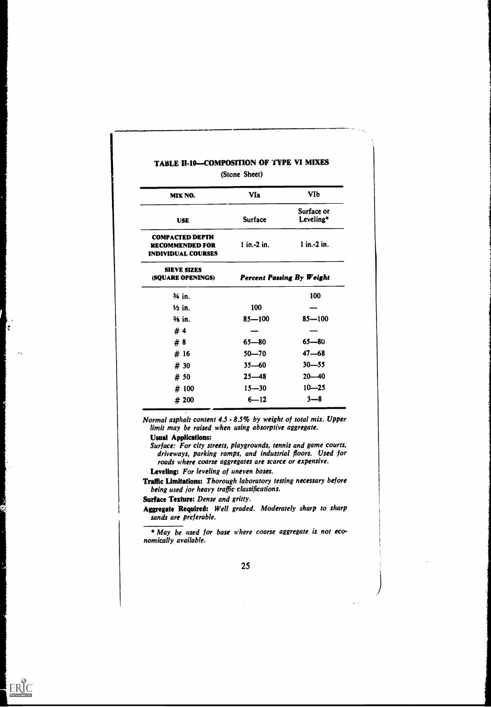
TABLE 11-10COMPOSITION OF TYPE VI MIXES
(Stone Sheet)
MIX NO.
USE
COMPACTED DEPTHRECOMMENDED FOR
INDIVIDUAL COURSES
VIa VIb
Surface orSurface Leveling*
1 in.-2 in. 1 in.-2 in.
SIEVE SIZES(SQUARE OPENINGS) Percent Passing By Weight
in.
1/2 in. 100
100
in. 85-100 85-100# 4# 8 65-80 65-80# 16 50-70 47-68# 30 35-60 30-55# 50 25-48 20-40# 100 15-30 10-25# 200 6-12 3-8
Normal asphalt content 4.5 - 8.5% by weight of total mix. Upperlimit may be raised when using absorptive aggregate.Usual AppHcations:Surface: For city streets, playgrounds, tennis and game courts,
driveways, parking ramps, and industrial floors. Used forroads where coarse aggregates are scarce or expensive.
Leveling: For leveling of uneven bases.
Traffic Limitations: Thorough laboratory testing necessary beforebeing used bor heavy traffic classifications.
Surface Texture: Dense and gritty.Aggregate Required: Well graded. Moderately sharp to sharp
sands are preferable.
* May be used for base where coarse aggregate is not eco-nomically available.
25

, .44 74741-IP4tiftee-*,
TABLE II-IICOMPOSITION OF TYPE VII MIXES
(Sand Sheet)
MIX NO. VIIa
USE Surface*
COMPACTED DEPTHRECOMMENDED FOR
INDIVIDUAL COURSESV.2 in.-1 in.
SIEVE SIZES(SQUARE OPENINGS) Percent Passing By Weight
Ns in. 100
# 4 85-100
# 8 80-95
# 16 70-89
# 30 t'55-80
#50 30-60
# 100 10-35
# 200 4-14
Normal asphalt content 7.0 - 11% by weight of total mix. Upperlimit may be raised when using absorptive aggregate.
Usual Applications: 4., a surface on city streets and highwayswhere coarse aggregates are not economically available.
Traffic Limitations: Thorough laboratory testing necessary beforebeing used for heavy traffic classifications.
Surface Texture: Dense and gritty.
Aggregate Required: Well graded. Moderately sharp to sharpsand preferable.
* May be used for base where coarse aggregate is not eco-nomically available.
26

TABLE II-12COMPOSITION OF TYPE VIII MIXES
(Fine Sheet)
MIX NO. Villa
USE Surface
COMPACTED DEPTHRECOMMENDED FOR
INDIVIDUAL COURSES
1/2 in.-11/2 in.
SIEVE SIZES(SQUARE OPENINGS) Percent Passing By Weight
# 4 100
# 8 95-100
# 16 85-98
# 30 70-95
# 50 40-75
# 100 20-40
# 200 8-16
Normal asphalt content 7.5 - 12.0% by weight of total mix.
Upper limit may be raised when using absorptive aggregate.
Usual Application: As a surface on city streets where coarse
aggregates are not economically available.
Traffic Lhnitations: Thorough laboratory testing necessary before
being 14,51d for heavy traffic classifications.
Aggregate Required: Well graded, sharp sand with inherent
stability.
27

TA
BL
E I
I-13
-CO
MPI
LA
TIO
N O
F M
IX T
YPE
S
Mix
Num
ber
21/2
in.
11/2
In.
1 ha
.In
.1/
2 In
.44
In.
No
4N
o. S
No.
16
No.
30
No.
50
No.
100
No.
200
Perc
ent
Asp
halt
Ia10
035
-70
0-15
0-5
0-3
3.0-
4.5
IIa
100
40-8
55-
200-
43.
0-6.
0II
b10
070
-100
20-4
05-
200-
43.
0-6.
0H
c10
070
-100
45-7
520
-40
5-20
0-4
3.0-
6.0
IId
100
70-1
0035
-60
15-3
55-
200-
43.
0-6.
0H
e10
070
-100
50-8
025
-50
10-3
05-
200-
43.
0-6.
0II
Ia10
075
-100
35-5
520
-35
10-2
26-
164-
122-
83.
0-6.
0M
b10
075
-100
60-8
535
-55
20-3
510
-22
6-16
4-12
2-8
3.0-
6.0
HIc
100
75-1
0060
-85
30-5
020
-35
5-20
3-12
2-8
0-4
3.0-
6.0
IIId
100
75-1
0045
-70
30-5
020
-35
5-20
3-12
2-8
0-4
3.0-
6.0
IV 00M
e10
075
-100
60-8
540
-65
30-5
020
-35
5-20
3-12
2-8
0-4
3.0-
6.0
IVa
100
80-1
0055
-75
35-5
018
-29
13-2
38-
164-
103.
5-7.
0IV
b10
080
-100
70-9
050
-70
35-5
018
-29
13-2
38-
164-
103.
5-7.
0IV
c10
080
-100
60-8
048
-65
35-5
019
-30
13-2
37-
150-
83.
5-7.
0lV
d10
080
-100
70-9
055
-75
45-6
235
-50
19-3
013
-23
7-15
0-8
3.5-
7.0
Va
100
85-1
0065
-80
'50-
6537
-52
25-4
018
-30
10-2
03-
104.
0-7.
5V
b10
085
-100
65-8
050
-65
37-5
225
-40
18-3
010
-20
3-10
4.0-
7.5
VIa
100
85-1
0065
-80
50-7
035
-60
25-4
815
-30
6-12
4.5-
8.5
VIb
100
85-1
0065
-80
47-6
830
-55
20-4
010
-25
3-8
4.5-
8.5
Vila
100
85-1
0080
-95
70-8
955
-80
30-6
010
-35
4-14
7.0-
11.0
VII
Ia10
095
-100
85-9
870
-95
40-7
520
-40
8-16
7.5-
12.0
NO
TE
For
curb
mix
com
posi
tion
refe
r to
the
Asp
halt
Inst
itute
'sS
peci
ficat
ion
and
Con
stru
ctio
n M
etho
ds fo
r A
spha
lt C
urbs
and
Gut
ters
,Sp
ecif
icat
ions
Ser
ies
No.
3 (
SS-3
).Fo
r m
ix c
ompo
sitio
ns f
or h
ydra
ulic
app
licat
ions
ref
er to
Asp
halt
Inst
itute
'sA
spha
lt in
Hyd
raul
ic S
truc
ture
s(M
S-12
).

TA
BL
E I
I-14
CO
MPO
SIT
ION
OF
SKIP
-GR
AD
ED
MIX
ES
MIX
NO
.Sk
ip A
Skip
B
USE
Surf
ace
orL
evel
ing,
Lev
elin
gor
Bas
e
Skip
C
Bas
e
SIE
VE
SIZ
ES
(SQ
UA
RE
OPE
NIN
GS)
Perc
ent P
assi
ng B
y W
eigh
t
2 in
.10
0
tv vp11
/2 in
.10
095
-100
1 in
. in.
100
95-1
0060
-80
1/2
in.
95-1
0060
-80
* 4
50-7
030
-50
25-4
5*
830
-50
20-4
015
-35
* 50
5-25
5-25
3-20
* 20
02-
101-
100-
5
Nor
mal
asp
halt
cont
ent 4
.0 -
9.0
% b
yw
eigh
t of
tota
l mix
.U
pper
lim
it m
ay b
e ra
ised
whe
n us
ing
abso
rptiv
e ag
greg
ate.

(Chapter III
CONSTRUCTION SPECIFICATIONS MRASPHALT CONCRETE AND OTHER
PLANT-MIX TYPES
NOTE TO THE ENGINEER:* This part of themanual presents specifications for asphalt concrete(or plant-mix) paving. High quality paving mixesrequire adherence to the following:Proper mix design and control by laboratory meth-ods;
Use of quality aggregates;
Close limits for aggregate grading;
Close job tolerances;
Strict requirements for mixing plants and well-ad justed and operated construction equipment;Specific compaction (density) requirements;Specific smoothness requirements;
Strict engineering inspection and control.Before using these specifications definite require-ments or limits, selected or determined by design,should be inserted in those places where it is indi-cated.See Appendix C for charts showing possible causesof deficiencies in hot plant-mix paving mixtures andpossible causes of imperfections in finished pave-ments.
A. Description
3.01 GENERALThe paving mix shall be com-posed of mineral aggregate and asphalt cement thor-ougly mixed, in a plant meeting the requirements of
"Notes to the Engineer" found in these specifications arefor the Engineer's information only and do not form a part ofthe general instruction. These references are boxed.
30

these specifications, until all aggregate particles arecoated completely with asphalt. The finished pavementshall conform in all respects with lines, grades, dimen-sions and cross sections shown on the project plans.
3.02 MIX NUMBERS AND THICKNESSES.Thepaving mix shall be laid in course ( s) . The
Mix Number designation dnd compacted average thick-
ness of each course shall be as follows:*
PAVING COURSE MIX NO. COMPACTED THICKNESS
Base inches
Leveling inches
Sruface inches
The compacted thickness of any single constructedcourse shall not exceed three times the largest aggre-gate size or a maximum of four (4) inches for basecourse, three (3) inches for leveling course, or two (2)inches for surface course.
3.03 PRIME AND TACK COAT.--Priming of baseand applying asphalt tack coat to existing paved sur-faces shall be done with the following types of asphaltat the rates specified:**
For Priming Baseat the rate of
For Applying Tack Coatat the rate of
asphaltgallon per sq. yd.
asphaltgallon per rq. yd.
* NOTE TO THE ENGINEER: Mix Number Designa-tions correspond with Mix Number to be specified inArticle 3.12.
** NOTE TO THE ENGINEER: Under normal circum-stances, these operations may be done with the follow-ing materials within the application ranges shown:
Priming Base: 0.2 to 0.5 gallon of MC-30 per sq. yd.
Applying Tack Coat: 0.05 to 0.15 gallon of SS-1,SS-1h, SS-K or SS-Kh per sq. yd. ln order to applythe above limited quantities uniformly, emulsion isdiluted with equal parts of water.
,
31
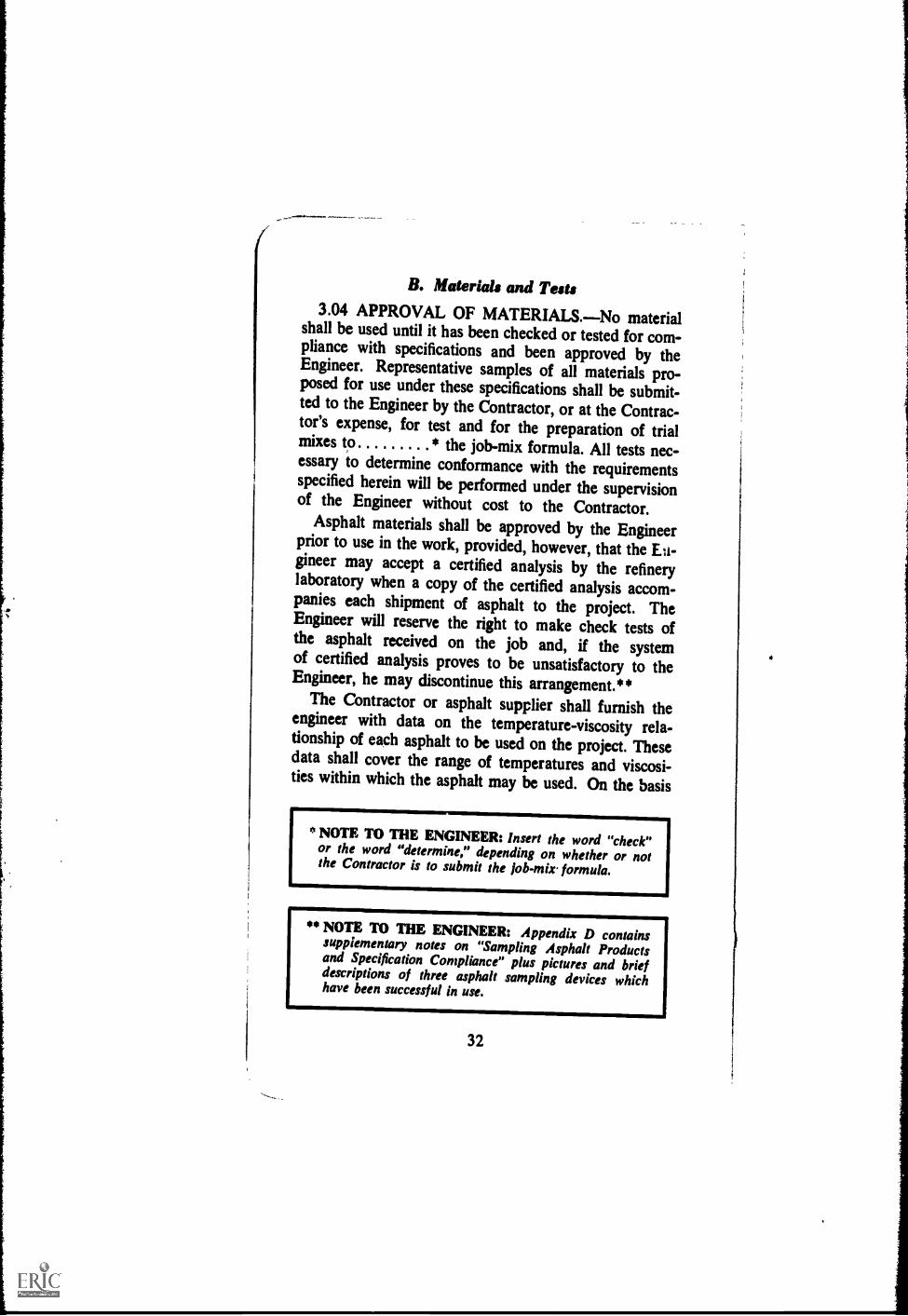
B. Materials and Tests3.04 APPROVAL OF MATERIALS.No material
shall be used until it has been checked or tested for com-pliance with specifications and been approved by theEngineer. Representative samples of all materials pro-posed for use under these specifications shall be submit-ted to the Engineer by the Contractor, or at the Contrac-tor's expense, for test and for the preparation of trialmixes to * the job-mix formula. All tests nec-essary to determine conformance with the requirementsspecified herein will be performed under the supervisionof the Engineer without cost to the Contractor.
Asphalt materials shall be approved by the Engineerprior to use in the work, provided, however, that the En-gineer may accept a certified analysis by the refinerylaboratory when a copy of the certified analysis accom-panies each shipment of asphalt to the project. TheEngineer will reserve the right to make check tests ofthe asphalt received on the job and, if the systemof certified analysis proves to be unsatisfactory to theEngineer, he may discontinue this arrangement.**
The Contractor or asphalt supplier shall furnish theengineer with data on the temperature-viscosity rela-tionship of each asphalt to be used on the project. Thesedata shall cover the range of temperatures and viscosi-ties within which the asphalt may be used. On the basis
* NOTE TO THE ENGINEER: Insert the word "check"or the word "determine," depending on whether or notthe Contractor is to submit the fob-mix. formula.
** NOTE TO THE ENGINEER: Appendix D containssupplementary notes on "Sampling Asphalt Productsand Specification Compliance" plus pictures and briefdescriptions of three asphalt sampling devices whichhave been successful in use.
32
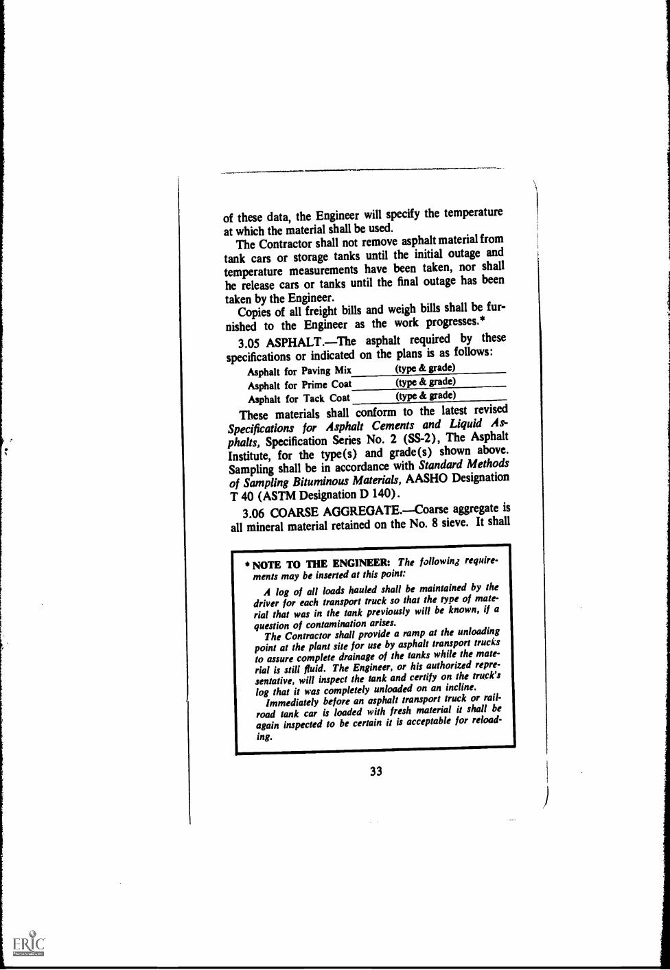
of these data, the Engineer will specify the temperatureat which the material shall be used.
The Contractor shall not remove asphalt material from
tank cars or storage tanks until the initial outage and
temperature measurements have been taken, nor shall
he release cars or tanks until the final outage has been
taken by the Engineer.Copies of all freight bills and weigh bills shall be fur-
nished to the Engineer as the work progresses.*
3.05 ASPHALT.The asphalt required by these
specifications or indicated on the plans is as follows:
Asphalt for Paving Mix (type & grade)
Asphalt for Prime Coat (type & grade)
Asphalt for Tack Coat (type & grade)
These materials shall conform to the latest revised
Specifications for Asphalt Cements and Liquid As-
phalts, Specification Series No. 2 (SS-2), The Asphalt
Institute, for the type(s) and grade(s) shown above.
Sampling shall be in accordance with Standard Methods
of Sampling Bituminous Materials, AASHO Designation
T 40 (ASTM Designation D 140).
3.06 COARSE AGGREGATE.Coarse aggregate is
all mineral material retained on the No. 8 sieve. It shall
* NOTE TO ME ENGINEER: The following require-
ments may be inserted at this point:
A log of all loads hauled shall be maintained by thedriver for each transport truck so that the type of mate-rial that was in the tank previously will be known, if aquestion of contamination arises.
The Contractor shall provide a ramp at the unloadingpoint at the plant site for use by asphalt transport trucksto assure complete drainage of the tanks while the mate-
rial is still fluid. The Engineer, or his authorized repre-sentative, will inspect the tank and certify on the truck's
log that it was completely unloaded on an incline.Immediately before an asphalt transport truck or rail-
road tank car is loaded with fresh material it shall be
again inspected to be certain it is acceptable for reload-
ing.
33
1

I consist of crushed stone, crushed slag, crushed gravel,or combinations thereof, or of material naturally occur-ring in a fractured condition (such as disintegrated gran-ite) or of a highly angular natural aggregate with pittedor rough surface texture. For light and medium trafficclassifications, uncrushed aggregate may be used.
Crushed slag shall be air-cooled, blast-furnace slaguniform in density and quality. When tested by Methodof Test for Unit Weight of Aggregate, AASHO Designa-tion T 19 (ASTM Designation C 29) it shall have a com-pacted weight of not less than 70 lbs. per cu. ft. (ó5 lbs.for 2 inches and larger) for each commercial size used.
All coarse aggregate shall be free from coatings ofclay, silt or other objectionable matter and shall not con-tain clay balls or other aggregations of fine material.The percentage of wear for coarse aggregate used inbase or leveling courses shall not be greater than 50when tested by Method of Test for Abrasion of CoarseAggregate, AASHO Designation T 96 (ASTM Designa-tion C 131). The percentage of wear of coarse aggregateused in surface course mixes shall not be greater than40 when so tested.
For heavy traffic classification pavements, coarse ag-gregate other than slag or naturally occurring rough-textured or pitted-surfaced aggregate shall contain atleast 60 percent by weight of crushed pieces having twoor more surfaces or faces produced by fracture. Coarseaggregates shall be tested for soundness by Method ofTest for Soundness of Aggregates, AASHO Designation
NOTE TO THE ENGINEER: In paving mixturesused for base courses, which are to be covered bysurface courses of minimum thickness as requiredby the Asphalt Institute's manual, Thickness Design(MS-1), the requirement for crushed (fractured orangular) coarse aggregate may be relaxed providedthe mixture meets all other design criteria.
34

T 104 (ASTM Designation C 88) or will have been satis-factorily proved sound through adequate record of serv-ice. When tested for soundness, the number of cyclesshall be , the solution shall be , andthe maximum loss shall be * Aggregateshaving known polishing characteristics shall not be usedin mixes for the surface course.
3.07 FINE AGGREGATE. Fine aggregate is allmineral matter passing the No. 8 sieve. It shall consistof natural sand and/or manufacture6 material derivedby crushing of stone, slag, or gravel.
The aggregate particles shall be clean, tough, durable,moderately sharp, and free from coatings of clay, silt orother objectionable matter and shall contain no clayballs or other aggregations of fine material. Fine aggre-gates shall be tested for soundness by Method of Testfor Soundness of Aggregates, AASHO Designation T 104(ASTM Designation C 88) or shall have a satisfactorysoundness record. When tested for soundness the num-ber of cycles shall be , the solution shall be
, the maximum loss shall be percent.*
3.08 MINERAL FILLER.Mineral filler shall con-sist of finely ground particles of limestone, hydrated lime,portland cement or other non-plastic mineral matter ap-proved by the Engineer. It shall be thoroughly dry andfree from lumps. When tested by Method of Test forSieve Analysis of Mineral Filler, AASHO Designation T37 (ASTM Designation D 546), it shall meet the follow-ing minimum gradation requirements:
* NOTE TO THE ENGINEER: The Engineer shouldinsert in the blank spaces the number of cycles, the solu-tion and percent loss which he desires to be used. TheAsphalt Institute recommends the following: Number ofcycles, 5; solution, sodium sulphate; maximum loss, 12percent.
35
-
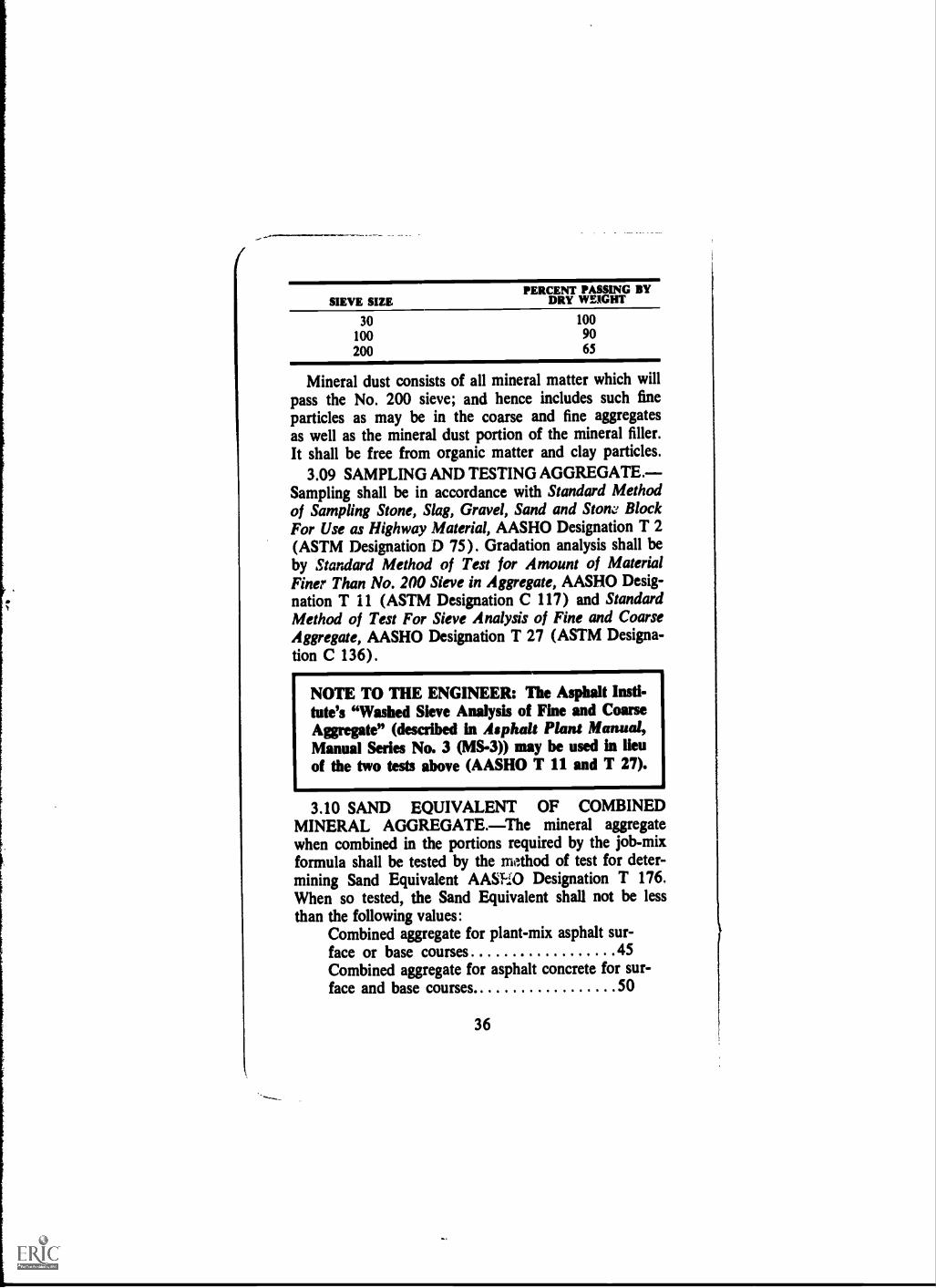
PERCENT PASSING BYSIEVE SIZE DRY WEIGHT
30 100
100 90
200 65
Mineral dust consists of all mineral matter which willpass the No. 200 sieve; and hence includes such fineparticles as may be in the coarse and fine aggregatesas well as the mineral dust portion of the mineral filler.It shall be free from organic matter and clay particles.
3.09 SAMPLING AND TESTING AGGREGATE.Sampling shall be in accordance with Standard Methodof Sampling Stone, Slag, Gravel, Sand and Stow BlockFor Use as Highway Material, AASHO Designation T 2(ASTM Designation D 75). Gradation analysis shall beby Stardard Method of Test for Amount of MaterialFiner Than No. 200 Sieve in Aggregate, AASHO Desig-nation T 11 (ASTM Designation C 117) and StandardMethod of Test For Sieve Analysis of Fine and CoarseAggregate, AASHO Designation T 27 (ASTM Designa-tion C 136).
NOTE TO THE ENGINEER: The Asphalt Insti-tute's "Washed Sieve Analysis of Fine and CoarseAggregate" (described in Asphalt Plans Manual,Manual Series No. 3 (MS-3)) may be used in lieuof the two tests above (A ASHO T 11 and T 27).
3.10 SAND EQUIVALENT OF COMBINEDMINERAL AGGREGATE.The mineral aggregatewhen combined in the portions required by the job-mixformula shall be tested by the method of test for deter-mining Sand Equivalent AASFIO Designation T 176.When so tested, the Sand Equivalent shall not be lessthan the following values:
Combined aggregate for plant-mix asphalt sur-face or base courses 45Combined aggregate for asphalt concrete for sur-face and base courses. 50
36

3.11 ASPHALT PAVING MIXES.Mixes shall besampled by Standard Methods of Sampling BituminousPaving Mixtures, AASHO Designation T 168 (ASTM
Designation D 979). The mixes will be tested by Method
of Test for Bitumen Content of Paving Mixtures by Cen-trifuge, AASHO Designation T 164 (ASTM Designation
D 1097), and the recovered aggregate will be sieved inaccordance with Method of Test for Mechanical Analysis
of Extracted Aggregates, AASHO Designation T 30.When recovered asphalt is required for further testing, it
will be obtained by Method of Test for Hot Extraction of
Asphaltic Materials and Recovery Gi Bitumen by theModified Abson Procedure, AASHO Designation T 170
(ASTM Designation D 762).
C. Composition of Mixes
3.12 GENERAL REQUIREMENTS.Paving mixesprepared eider these specifications shall be composedof aggrega'ta and paving asphalt within the limits setforth in the following tabulation:
Paving Course Combined Aggregites, TotalPassing, Percent by Weight.
MIX NUMBER *SIEVE SIZE(SQUARE OPENINGS)
21h in.Ph in.1 in.
3/4 in.1/2 in.3/8 in.#4#8#16#30#50#100#200Asphalt to be added**(% by weight of totalmix)
NOTE TO THE ENGINEER: The
Engineer will insert suitable aggre-
gate gradation limits and lit !is on
uphalt consent in this space. These
limits may be selected on the basis
of information contained in Chapter
II, "Procedures for Developing Spe-
cifications." One such tabulation
should be provided for each adz to
be used on the project.
* Mix numbers correspond to those set forth in Article 3.02.
** The upper limit may be raised when absorptive aggregatesare used.
37

The Engineer will a job-mix formula foreach mix number within the limits specified above.*
The gradations are applicable for aggregate mixes inwhich the specific gravity of two or more size fractionsdoes not differ by more than twenty (0.20) points. If thespecific gravity of two or more size fractions differs bymore than twenty (0.20) p. 'nts, gradations should beadjusted to an equivalent percentage by volume.**
The maximum permiss:ble variation from the job-mixformula within the specification limits, shall be as fol-lows:
SIEVE SIZE
PERMISSIBLE VARIATION,PERCENT BY WEIGHT
OF TOTAL MIX
#4 and larger 5.0#8 4.0#21) 3.0#200 1.0
Asphalt 0.3
3.13 SPECIAL REQUIREMENTS.Laboratory testspecimens of paving mixes, combined in the proportionsof the job-mix formula, shall be prepared and testedin lccordance with the procedures set forth for the
(Marshall, Hveem or Hubbard-Field)
Method of mix design in The Asphalt Institute manual,
* NOTE TO ENGINEER: Insert the word "approve" orthe word "specify," depending on whether or not theContractor is to submit the job-mix formula.
" NOTE TO THE ENGINEER: Method for adjustingproportions of aggregates of varying specific gravitymay be found in Appendix A of The Asphalt InstituteManual, Mix Design Methods for Asphalt Concreteand Other Hot-Mix Types, Manual Series No. 2.
38

Mix Design Methods for Asphalt Concrete and Other Hot-Mix Types, Manual Series No. 2 (MS-2).
Test requirements and criteria for the paving mixesprepared under these specifications shall be as follows:
CRITERIA FORTEST LIMITSMIX NO.
NOTE TO THE ENGINEER: Enter in this space thecriteria for test ihnits for each mix in accord with themethod of mix design specified above. Suggested criteriafor test limits are set forth in Table 11-4. In addition,state any special provisions necessary because of the typeand quality of local aggregate or because of other localconditions.
D. Equipment
3.14 GENERAL EQUIPMENT REQUIREMENTS.All equipment furnished by the Contractor shall meetthe requirements of this section and shall be maintainedin its best mechanical condition. Equipment shall beserviced and lubricated away from the paving site; unitsthat drip fuel, oil and grease shall be removed fromthe project until such leakage is corrected.
3.15 ASPHALT MIXING PLANTS.Plants used bythe Contractor for preparation of the asphalt paving mixshall conform to all of the conditions under "Require-ments for All Plants." All batch mixing plants shallmeet the additional conditions under "Special Require-ments for Batch Type Plants," and all continuous mix-ing plants shall conform to the additional requirementsunder "Special Requirements for Continuous MixingPlants."
3.16 REQUIREMENTS FOR ALL PLANTS.(1) Uniformity. The plants shall be designed, co-
ordinated, and operated to produce a uniform mixwithin the job-mix tolerances as covered in Section C.
(2) Equipment for Preparation of Asphalt. Tanks
39
for storage of asphalt shall be provided with a devicefor controlled heating of the material to temperaturerequirements set forth in the specifications. Heatingshall be accomplished so that no flame shall come incontact with the heating tank. A circulating system ofadequate size to insure proper and continuous circula-tion of asphalt between storage tank and mixer duringthe entire operating period shall be provided. The dis-charge end of the circulating pipeline shall be keptbelow the surface of the asphalt in the tank while thepump is in operation. Storage tank capacity shall besufficient to hold enough asphalt for at least one day'srun.
(3) Cold Aggregate Feeder. The plant shall be pro-vided with an accurate mechanical means for feedingthe mineral aggregate into thc dryer to secure a uni-form production and a constant temperature. Thefeeder or feeders shall be capable of delivering, inpreset proportions, the maximum number of aggregatesizes required. When more than one cold elevator isused, each shall be fed as a separate unit and the in-dividual controls shall be integrated with a total mas-ter control.
(4) Dryer. The plant shall include a rotary drumdryer that will continuously agitate the mineral ag-gregates during the heating and drying process. Itshall be capable of continuously supplying aggregate,at the temperature and maximum moisture contentspecified, to the mixing unit operating at its capacity.
(5) Screens. Plant screens capable of separating allaggregates to the sizes required for proportioning, andhaving normal capacity slightly in excess of the fullcapacity of the mixer or the dryer, shall be provided.The Contractor shall expose the screens for inspectionat the request of the Engineer. The plant screens shallhave an efficiency such that the bins shall have notmore than the following percentages of undersize andoversize:
40
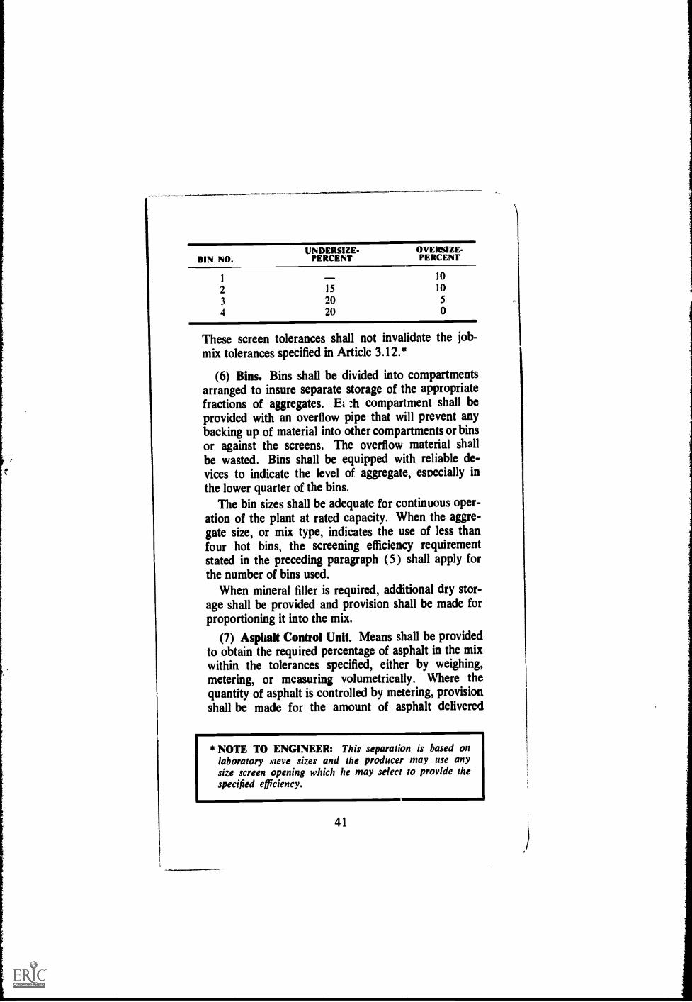
UNDERSIZE- OVERSIZE-BIN NO. PERCENT PERCENT
1 10
2 15 10
3 20 5
4 20 0
These screen tolerances shall not invalidate the job-mix tolerances specified in Article 3.12.*
(6) Bins. Bins shall be divided into compartmentsarranged to insure separate storage of the appropriatefractions of aggregates. Ei ;11 compartment shall beprovided with an overflow pipe that will prevent anybacking up of material into other compartments or binsor against the screens. The overflow material shallbe wasted. Bins shall be equipped with reliable de-vices to indicate the level of aggregate, especially inthe lower quarter of the bins.
The bin sizes shall be adequate for continuous oper-ation of the plant at rated capacity. When the aggre-gate size, or mix type, indicates the use of less thanfour hot bins, the screening efficiency requirementstated in the preceding paragraph (5) shall apply forthe number of bins used.
When mineral filler is required, additional dry stor-age shall be provided and provision shall be made forproportioning it into the mix.
(7) Asphalt Control Unit. Means shall be providedto obtain the required percentage of asphalt in the mixwithin the tolerances specified, either by weighing,metering, or measuring volumetrically. Where thequantity of asphalt is controlled by metering, provisionshall be made for the amount of asphalt delivered
* NOTE TO ENGINEER: This separation is based onlaboratory sieve sizes and the producer may use anysize screen opening which he may select to provide thespecified efficiency.
41

through the meter to be readily checked by weight.Steam jacketing or other insulation which will maintainthe specified temperature of asphalt in pipelines, me-ters, weigh buckets, spray bars, flow lines or othercontainers shall be provided.
(8) Thermometric Equipment. An armored ther-mometer reading from 2000 to 400°F. shall be fixed
in the asphalt feed line at a location near the dischargevalve at the mixer unit.
The plant shall be further equipped with an ap-proved dial-scale, mercury-actuated thermometer, arecording electric pyrometer, or other approved ther-mometric instrument having an accuracy of -±-5°F.placed at the discharge chute of the dryer to registerautomatically, or indicate, the temperature of theheated aggregate. Any thermometric instrument usedshall be sensitive to a rate of temperature change notless than 10°F. per minute.
The Engineer shall have the right to test the accur-acy of thermometric instruments for better control ofasphalt, aggregate and mix temperatures. He maydirect the immediate repair or replacement of any in-strument yielding inaccurate or inconsistent readings.
(9) Dust Collector. The plant shall be providedwith a dust collector, designed to waste, or return ina constant and uniform flow to the hot elevator bymechanical means, all or part of the material collected.Prior to permitting the return of such collected dust,the Engineer will examine its characteristics in rela-tion to the mix requirements, and will designate thequantity to be returned.
The plant shall have a mixer cover and such addi-tional housing as may be necessary to insure theproper control of dust.
(10) Safety Requirements. Adequate and safe stair-ways to the mixer platform and guarded ladders toother plant units shall be provided. All gears, pulleys,
42
)

1
chains, sprockets and other dangerous moving partsshall be dell guarded and protected. Ample and unob-structed space for the operator shall be provided on themixing platform. A clear and unobstructed passageshall be maintained at all times in and around thetruck loading space. This space shall be free fromdrippings from the mixing platform. A ladder, or plat-form, shall be so located at the truck loading space topermit easy and safe inspection or sampling of themix as it is delivered into the truck. Overhead pro-tection shall be provided where necessary.3.17 SPECIAL REQUIREMENTS FOR BATCH
TYPE PLANTS.(1) Plant Scales. Scales for any weigh box or
hopper may be of either the springless dial or beamtype and shall be of an established make and design,accurate to 0.5 percent of the indicated load.
Dial scales shall be designed, constructed and in-stalled in such manner as to be free from vibration.All dials shall be so located as to be plainly visible tothe operator at all times. The numerals on the dialshall be of such size that they can be read at a distanceof 25 feet. The end of the pointer shall be set close tothe face of the dial to minimize parallax. The scaleshall be provided with adjustable pointers for markingthe weight of each material to be weighed into thebatch.
When scales are of the beam type, there shall be atare beam for balancing the hopper and a separatebeam for the aggregate from each hot bin. A telltaledial shall be provided that will start to function whenthe load being applied is within 100 pounds of theweight desired. Each beam shall have a locking devicedesigned and so located that the beam can easily besuspended or thrown into action.
Scales for the weighing of asphalt shall conform tothe requirements for aggregate scales, except thatbeam scales shall consist of a full capacity beam anda tare beam. The minimum graduation shall be not
43
greater than two pounds and there shall be attached atelltale device which will start to function when theload being applied is within 25 pounds of the weightdesired. Dial scales for weighing the asphalt shall readto the nearest pound. All scales for weighing the as-phalt shall have a capacity of not more than 15 percentof the normal capacity of the mixer.
Scales shall be tested and sealed as often as the En-gineer may deem it necessary to insure their accuracy.All weighing equipment shall be well constructed andof a design which will permit easy realignment andadjustment. Weighing equipment that easily gets outof adjustment shall be replaced when so ordered bythe Engineer. The Contractor shall provide and have onhand at least ten 50-pound standard weights for fre-quent testing of all scales. For each scale, a suitablecradle, or platform, shall be provided for applying thetest load so that the load is distributed uniformly. Thetest weights shall be kept clean and stored near thescales.
Volumetric proportioning of heated and screededaggregates will be permissible provided the volumetricsystem is standard equipment furnished for the plant.The scales used for checking volumetric proportionsshall be accurate within 0.5 percent of the ch,(.7,, testload.
(2) Weigh Box or Hopper. Equipment shall includea weigh box or hopper, large enough to hold afull batch without hand raking or running over, for ac-curately weighing each bin size of aggregate. Theweigh box or hopper fulcrums and knife edges shallbe so constructed that they will not be easily thrownout of alignment. Gates on both bins and hopper shallprevent leakage when they are closed. An interlockingdevice which prevents the opening of more than onegate at a time shall be provided. Proportioning of ag-gregates and charging of mixer shall be performed soas to blend the aggregates thoroughly and preventsegregation in the mixer.
44
i

Automatic plants may proportion all aggregates bysimultaneous measuring if a weigh hopper with aseparate compartment for each bin size, calibrated
by weight, is used.
(3) Asphalt Measuring Equipment. Asphalt meas-uring equipment provided on the plant shall accurately
measure into each batch the required amount of as-
phalt within a tolerance of plus or minus two pounds.
When an asphalt bucket is used, it shall be a non-tilting type provided with a loose sheet-metal cover.The capacity of the asphalt bucket shall be at least 10
percent in excess of the weight of asphalt required
for a one-batch mix. The plant shall have a steam-
jacketed, quick-closing, non-dripping, charging valve.
The length of the discharge opening or spray bar shall
be not less than three-fourths of the length of the mixer
and it shall discharge directly into the mixer. The dis-
charge system shall be designed and arranged to de-
liver the asphalt the full length of the mixer in a thin,
uniform sheet or in multiple streams or sprays.
When a volumetric meter is used, it shall automatic-ally meter the asphalt into each batch. The dial to
indicate the amount of asphalt shall have a capacity of
at least 10 percent in excess of the weight or gallons of
asphalt required in one batch. The meter shall be con-
structed so that it may be locked at any dial setting
and will automatically reset to this reading after the
addition of asphalt to each batch. The dial shall be in
full view of the mixer operator. The flow of asphalt
shall be controlled to begin automatically when the dry
mixing period is over. All of the asphalt required for
one batch shall b; discharged in not more than
15 seconds after the flow has started. The size and
spacing of the spray bar openings shall provide a uni-
form application of asphalt the full length of the mixer.
The section of the asphalt flow line between the charg-
ing valve and the spray bar shall be provided with a
valve and outlet for checking and testing the accuracy
of the meter.
45

(4) Mixer Unit for Batch Method. The plant shallinclude a batch mixer and a batch capacity of not less
than pounds.* It shall be capable of pro-ducing, uniformly, a mix within the job-mix tolerancesestablished in Article 3.12. Dovia don in size of batcheswill be permitted to provide for mixing batches downto 20 percent below and up to 15 percent above therated capacity of the mixer, provided the quality ofthe mix is not impaired.
The clearance of the blades from all fixed and mov-ing parts shall not exceed inch. The paddles shallbe set to insure a completely uniform mixture. If notenclosed, the mixer box shall be equipped with a dusthood to prevent loss of dust. The mixer shall be soconstructed as to prevent leakage of contents.
(5) Time Lock and Batch Counter. The mixer shallhave an accurate time control to lock the weigh boxgate after the charging of the mixer until the closingof the mixer gate at the completion of the cycle. Thetime lock shall also lock the asphalt bucket throughoutthe dry and wet mixing periods. Control of the timingshall be flexible, permitting adjustment of cycles up tothree minutes in five second intervals. A mechanicalbatch counter, designed to register only completelymixed batches, shall be installed.3.18 SPECIAL REQUIREMENTS FOR CONTIN-
UOUS MIXING PLANTS.(1) Gradation Control Unit. The plant shall include
means for accurately proportioning each bin size ofaggregate either by weight or by volumetric measure-ment.
When gradation control is by volume, the unit shallinclude a feeder mounted under the bins. Each bincompartment shall have an accurately controlled me-
* NOTE TO THE ENGINEER: The Engineer shouldspecify the minimum size plant or plants which he willrequire for the project.
46

chanically adjustable gate to form an opening for volu-metrically measuring the material drawn from it. Theopening shall be rectangular and provided with a lock.Indicators shall be provided on each gate to show thegate opening in inches. Mineral filler, if specified,shall be proportioned separately from a hopperequipped with an adjustable feed which may be accur-ately and conveniently calibrated and which shall beinterlocked with the aggregate and asphalt feeds.
(2) Weight Calibration of Aggregate Feed.Samples shall be taken and weighed as a means ofcalibrating gate openings. Material shall be fed out ofa bin through the individual opening and byPassed to aleakproof test box. The material from each compart-ment shall be taken separately. The plant shallbe equipped to handle conveniently test samples weigh-ing not less than 200 pounds. A platform scale shall beprovided by the Contractor to weigh the test samplesto an accuracy of ±0.6 percent of the indicated load.
(3) Synchronization of Aggregate and Asphalt Feed.Positive interlocking control shall be assured betweenthe flow of aggregate from the bins and the flow of as-phalt from the meter or other proportioning device.This shall be accomplished by interlocking mechanicalmeans or by any positive method approved by the En-gineer.
The aggregate bins shall be provided with signal de-vices and controls which will warn of low levels andwhich will automatically stop the flow of all aggregateand asphalt to the mixer when the aggregate in any onebin is so low that the feeder will not operate at setcapacity. The asphalt storage system shall be providedwith signal devices and controls which will warn of lowlevels of asphalt and which will automatically stop theentire plant operation when the asphalt storage levelis lowered to the point of exposing the feed end of theasphalt suction line.
47

* NOTE TO THE ENGINEER: The performance ofautomatic screed controls has been proven and thesepaver attachments are recommended for obtaining thesmoothest pavements.
(4) Mixer Unit for Continuous Method. The plantshall include a continuous mixer of the twin pugmilltype capable of uniformly producing a mix within thejob-mix tolerance specified in Section C. The paddlesshall be of a type adjustable for angular position on theshafts and reversible to retard the flow of the mix. Theclearance of the paddles from all fixed and movingparts shall not exceed inch. The mixer shallcarry a manufacturer's plate giving the net volumetriccontents of the mixer at the several heights inscribedon a permanent gauge.3.19 PAVERS AND LAYDOWN MACHINES.
Mechanical self-powered pavers shall be capable of spread-ing the mix, within the specified tolerances, true to theline, grade, and crown indicated on the plans. A motorpatrol, equipped with an automatic blade control, maybe used for the leveling course.
Pavers shall be equipped with quick and efficientsteering devices and shall be capable of traveling bothforward and in reverse. They shall be equipped withhoppers and distributing screws which place the mixevenly in front of adjustable screeds.
The screed shall include any strike-off device operatedby cutting, crowding or Other action which is effectiveon mixes at workable temperatures without tearing,shoving or gouging them, and which produces a finishedsurface of an even and uniform texture. The screed shallbe adjustable as to height and crown and shall be equip-ped with a controlled heating device for use when re-quired. The screed shall strike off the mix to the depthand crosstsection specified without the aid of manual ad-justment during operation.*
Pavers shall be capable of spreading mixes withOutsegregation or tearing. They shall also be capable of
48

placing courses in thicknessses of from 1/2 inch to at leastthree inches, .and from widths of eight feet to at least13 feet. Extensions and cut-off shoes shall permitchanges in widths by increments of six inches, orsmaller.
3.20 ROLLERS.Rolling equipment shall consist ofsteel-wheeled rollers and pneumatic-tired rollers de-scribed as follows:
(1) Steel-Wheeled Rollers may be of three types:three-wheeled rollers, two-axle tandem rollers, andthree-axle tandem rollers. These rollers shall be equippedwith power units of not iess than four cylinders andunder working conditions shall develop contact pres-sures under the compression rolls of 250 to 350pounds per inch of width. Rollers shall be in goodworking condition and shall be equipped with a re-versing clutch. Rollers shall be equipped with adjusta-ble scrapers to keep the wheel surfaces clean and withefficient means of keeping them wet to prevent mixesfrom sticking. These surfaces shall have no flatareas, openings or projections which will mar the sur-face of the pavement.
The three-axle tandem rollers shall be so constructedthat, when locked in position for all treads to be in oneplane, the roller wheels are held with such rigidity that,it either front or center wheel is unsupported, the othertwo wheels will not vary from the plane more than 1/4inch.
(2) Pneumatic-Tired Rollers shall be self-propelled.The rollers shall be equipped with pneumatic tires ofequal size and diameter which are capable of exertingaverage contact pressures varying from 40 psi to 110psi by adjusting the ballast and/or tire inflation pres-sures. The wheels of the roller shall be so spaced thatone pass will accomplish one complete coverage equalto the rolling width of the machine. There shall be aminimum of 1/4 inch overlap of the tracking wheels.The wheels shall oscillate but not wobble. The rollershall be so constructed that the contact pressure shall
49
gt

be uniform for all wheels, and the tire pressure ofthe several tires shall not vary more than 5 lbs. per sq.in. Pneumatic-tired rollers shall be constructed withenough ballast space to provide uniform wheel load-ings as may be required. The total operating weightand tire pressure of the roller may be varied by orderof the Engineer to obtain contact pressures that willresult in the required density.*
(3) Trench Rollers shall have an auxiliary wheel(or roll) that operates outside the area to be com-pacted at such a distance from the pavement edge asto cause no damage thereto. It shall be mounted uponan axle that is adjustable in height. The auxiliarywheel (ouoll) shall be kept in such adjustment thatthe compression roll will develop a smooth, compactedsurface true to crown and grade. The rollers shall beso constructed that the guiding wheel (or roll) oper-ates either in tandem with the compression roll on thearea to be compacted or in tandem with the auxiliarywheel (or roll).
Trench rollers shall be equipped with smoothly oper-wring friction clutches of the reversing type and shallhave a smoothly operating brake of ample capacity.
The contact pressure per inch width of compressionroll shall be not less than 300 pounds and not greaterthan 365 pounds. The minimum allowable width ofcompaction shall be 15 inches.
Trench rollers shall be equipped with adjustablescrapers to keep the rolls clean and with efficientmeans of wetting the rolls to prevent mixes from stick-ing to them.
3.21 DISTRIBUTORS.The pressure distributorused for prime and tack coats shall distribute the re-quired amount of asphaltic material at the specified tem-
* NOTE TO THE ENGINEER: Refer to The AsphaltInstitute's Asphalt Paving Manuz,l, Manual Series No. 8(MS-8), for a discussion of tire size, wheel load and in-flation pressures.
50

perature and in a uniform spray, without atomization.The distributor shall be equipped with pneumatic tiresof such size and number that the surface being sprayedwill not be rutted or otherwise disturbed. It shall have abitumeter with a dial visible to the truck driver for main-taining the constant speed required for application at thespecified rate.
The pump shall be operated by a separate power unit,or by the truck power unit. It shall have a tachometerwith a dial readily visible to the operator, registeringgallons per minut.; passing through the nozzles.
The distributor shall be designed so that the normalwidth of application shall be not less than 12 feet, withprovision for the application of lesser or greater widthwhen necessary.
The distributor shall be equipped and operated so thatthe asphaltic material shall be circulated or agitatedthroughout the entire heating process. Means for accu-rately indicating at all times, the temperature of theasphaltic material shall be provided. The thermometerwell shall be so placed as not to be in contact with theheating tube.
3.22 HAUL TRUCKS.Vehicles used for the trans-portation of asphalt concrete from the plant to the siteof work shall have tight metal bottoms and shall be freefrom dust, screenings, petroleum oils, volatiles or othermineral spirits which may affect the mix being hauled.Trucks shall be provided with covers of sufficient size andweight to protect the load and to prevent cooling of theupper stirface. In cool weather or for long hauls, theentire contact area of each truck bed shall be insulated.The Contractor shall provide haul trucks of such size,speed and condition to insure orderly and continuousoperations.
3.23 TRUCK SCALES.Plant-mix asphalt, paid forby the ton, shall be weighed on platform scales furnishedby the Contractor, or on public scales at the Contractor'sexpense. The scales shall comply with all state lawsgoverning the use of scales and shall be tested and sealed
51

by an authorized public official, at the expense of theContractor, as often as the Engineer may deem neces-sary to insure their accuracy.
3.24 FIELD TESTING LABORATORY.--The Con-tractor shall provide a laboratory building or room at theplant site for the exclusive use of the Engineer for per-forming tests, keeping records, and making reports.The building shall have floor space of not less than140 square feet. It shall have at least two windows, oneof which must offer a clear and unobstructed view ofthe plant operator's platform at all times. It shall beweather-proofed, heated, and ventilated and shall con-tain a sink with cold running water, electricity, sturdilyconstructed benches, and tables as required by the Spe-cial Provisions. The room and its contents shall be se-cured by locks and catches and all keys shall be underthe control of the Engineer.
3.25 HAND TOOLS.Only lutes or rakes withcovered teeth shall be used during the spreading opera-tion and when finishing by hand.
Tamping irons used to consolidate the edges of thepavement courses shall be of sufficient weight to com-pact the edges to the same degree as the body of thepavement. Irons shall be designed to form an edge asnearly vertical as possible. Irons which seal the mate-rial by heat alone shall not be used. Tamping ironsused to consolidate the material along curbs, gutters andother structures inaccessible to the roller shall weighnot less than 25 pounds and shall have a bearing areanot exceeding 48 square inches. Mechanical compactionequipment, approved by the Engineer, may be used in-stead of tamping irons.
Straightedges, ten feet in length, shall be provided totest the finished surface.
E. Inspection and Control of Asphalt Mixing Plant3.26 GENERAL PROVISIONS.For verification of
weights and measures, character of materials and deter-mination of temperatures used in the preparation of the
52
paving mixes, the Engineer or his authorized represen-tative will at all times have access to all portions of themixing plant, aggregate plant, storage yards and otheifacilities for producing and processing the materials ofconstruction. All sampling and testing of processed andunprocessed material shall be under the control and di-rection of the Engineer, and shall t.e accomplished inaccordance with the provisions set forth in Section B,"Materials and Tests."
3.27 JOB-MIX FORMULA.The Engineer will
make frequent gradation analyses of the hot aggregatesand of the completed mix to be certain that the materialsbeing used and produced are within the tolerances ofthe job-mix formula and the specifications of the mixnumber being used. If the mix is found to be outside
of the job-mix formula tolerances, or outside of thespecification limits (as shown in Section C), correctionshall be made in quantities measured from the hot binsand adjustments made at the cold bin feeders.
3.28 SAMPLING AND TESTING.Stockpiles andbins will be sampled for gradation analysis and examinedfor dust coating and for other purposes, in compliancewith stated requirements.
Gradation analyses of each hot bin will be performedand a combined analysis computed at least twice a dayonce in the forenoon, and once in the afternoon. A
combined gradation analysis will be performed ., leasttwice a day. If materials do not run uniform, more fre-quent tests will be made.
When requested by the Engineer, the Contractor shallprovide representative samples by taking aggregate fromthe discharge of the aggregate through each of the hotbin gates, or by drawing aggregate from each bin throughthe mixing chamber (without asphalt) into a truck orother receptacle.
At least one sa.liple shall be taken from each 300 tonsof the mix being produced. Samples will be used to de-termine compliance with general and special require-ments set forth in Section C, "Composition of Mixes."
53

F. Corstruction Methods
3.29 WEATHER LIMITATIONS.When the mois-ture of the aggregate in the stockpile or from the dryerinterferes with the quality of mix production, or withnormal plant operations, or when pools of water are ob-served on the base, mixing and placing of hot-mix as-phalt will not be permitted.
The temperature of the surface on which the hot-mixasphalt is placed shall be not less than 40°F. When thesurface temperature on which the material is to beplaced falls below 50°F., precautions shall be taken tocompact the mix before it cools too much to obtain therequired density.
All loads shall be delivered continuously in coveredvehicles and immediately spread and compacted. Incold weather and for exceptionally long hauls, all trucksshall be insulated. All mixes shall be delivered at atemperature within 15°F. of that temperature speci-fied by the Engineer.
3.30 PREPARATION OF AREA TO BE PAVED.--The area to be paved shall be true to line and grade,and have a dry and properly prepared surface prior tothe start of paving operations. I t shall be free from allloose screenings, and other loose or foreign material.
Where a base is rough or uneven, a leveling courseshall be placed by use of a paver or motor grader andshall be properly compacted before the placing of sub-sequent courses.
When a leveling course is not required, all depressionsand other irregularities shall be patched or correctedand the work approved by the Engineer before the pav-ing operation begins. All fatty and unsuitable patches,excess crack or joint filler, and all surplus bituminousmaterial shall be removed from the area to be paved.Blotting of excessive deposits of asphalt with sand orstone shall not be permitted.
Where the area to be paved is a prepared soil or ag-gregate base, it shall be primed in accordance with theprovisions of Asphalt Institute Specification P-1, As-
54

i
phalt Pruning of Granular Type Base Courses. The
prime coat shall consist of an application of the asphaltic
material indicated, and at the rate specified in Section
A. The prime coat shall be allowed to cure properly be-
fore any further operations are permitted on the primed
area.A tack coat shall be applied when the surface to be
paved is an existing portland cement concrete, brick or
asphalt pavement. When a tack coat is required, it shall
consist of an application of the asphaltic material indi-
cated, and at the rate specified in Section A.
The surfaces of curbs, gutters, vertical faces of exist-
ing pavements and all structures in actual contact with
asphalt mixes shall be painted with a thin, complete
coating of asphaltic material to provide a closely
bonded, water-tight joint.3.31 PREPARATION OF PAVING ASPHALT.
The asphalt shall be heated at the paving plant to a tem-
perature at which it can be uniformly distributed
throughout the mix. It shall be delivered into the Con-
tractor's tank at a temperature not exceeding 350°F.,
and shall not be heated above this temperature for any
operation of the paving plant.
3.32 PREPARATION AND HANDLING OF AG-
GREGATES.Coarse and fine aggregates shall be
stored at the plant in such a manner that the separate
sizes will not become intermixed. Cold aggregates shall
be carefully fed to the plant in such proportions that sur-
pluses and shortages in the hot bins will not cause
breaks in the continuous operation. When loading ag-
gregate into stockpiles and into cars, barges, and trucks
the material shall be placed in such a manner as to pre-
vent segregation of aggregate sizes. Stockpiles shall
be built in uniform layers not exceeding five feet in
depth.Coarse and fine aggregate shall be sampled and
tested upon arrival at the plant in accordance with the
standard methods specified in Article 3.09. Samples of
coarse and fine aggregate shall be submitted to the En-
,
55

gincer for tcsting prior to the start of work, and as oftenthereafter as requested by the Engineer.
When coarse aggregate grading is such that the mate-rial will tend to segregate during stockpiling orhandling, it shall be supplied in two or more sizes. Eachsize of coarse aggregate required to produce the com-bined gradation specified shall he placed in individualstockpiles at the plant site and separated by bulkheadsor other means approved by the Engineer. Likewise,
when it is necessary to blend fine aggregates from one
or more sources to produce the combined gradation,each source or size of fine aggregate shall also be placedin individual stockpiles. Aggregate from the individnalstockpiles shall be fed through separate bins to the coldelevator feeders. They shall not be blended in the stock-
pile.
(1) Drying. The aggregate shall be thoroughly driedand heated to provide a paving mix temperature within
a tolerance -±15°F. of that specified by the Engineer.
The moisture content of the heated and dried aggre-gate shall not exceed percent.* The quantityof material fed through the dryer shall in all cases, beheld to an amount which can be thoroughly dried andheated in accordance with that specified in "Propor-tioning and Mixing."
(2) Screening. Aggregates shall be screened into
sizes such that they may be recombined into a gra-dation meeting the requirements of the job-mixformula.
(3) Hot Aggregate Storage. Hot screened aggregatestorage shall be accomplished in such a manner as tominimize segregation and loss of temperature of theaggregate.
* NOTE TO THE ENGINEER: The Engineer shouldspecify here the maximum amount of moisture to bepermitted. lt is suggested that in most cases this should
be 0.5 percent or less.
56
3.33 PROPORTIONING AND MIX ING.To aidin determining the proper temperature of the completedbatch, current viscosity data shall be provided and shallbe available at the plant at all times. With informationrelative to the viscosity of the particular asphalt beingused, the temperature of the completed mix at the plantand at the paver shall be designated by the Engineerafter discussing with the Contractor the hauling andplacing conditions.
The asphalt shall be heated so that it can be distrib-uted uniformly throughout the batch. For mixing appli-cations, the specified temperature generally (see Ar-ticle 1.04) will be such that the asphalt viscosity is within
the range of 150-300 centistokes (75-150 seconds, Say-bolt Furol). The material shall be sufficiently fluid to
pi iduce a complete coating on every particle of aggregatewithin the specified mixing time. The temperature of th2
aggregates and asphalt immedit.tely prior to mixing shallbe approximately that of the completed batch.
When the mix is produced in a batch-type plant, theaggregate shall be weighed accurately in the designatedproportions to provide the specified batch weight. Thetemperature of the aggregate at the time of introductioninto the mixer shall be as directed by the Engineer, witha tolerance of -±15°F. In no case, however, shall thetemperature of the mixture exceed 350°F.
Continuous mix plants shall, in general, he controlledin the same manner as batch-type plants. Details ofcontrol, differing because of the continuous mixing
principle, shall be governed by instructions issued by
the plant manufacturer, wherever these instructions
are not contrary to these specifications.
3.34 CONTROL OF MIXING TIME.The drymixing period is the interval of time between the openingof the weigh box gate and the application of the asphalt.The wet mixing period is the interval of time betweenthe application of all asphalt and the opening of the mixergate for discharge. When it is applied by a spray sys-tem, the wet mixing time shall begin with the start of
the asphalt spray.
57

(I) Batch Type Plants. * The Engineer will desig-nate the length of time of both the dry and wet mixingperiods to insure a uniformly and completely coatedmix. Mixing period time shall not be altered unlessso ordered by the Engineer. A dry mixing period ofnot less than five seconds shall precede the additionof the asphalt to the mix. Excess wet mixing shall beavoided. Wet mixing shall continue as long as is nec-essary to obtain a thoroughly blended mix but shallnot exceed 75 seconds nor be less than 30 seconds.
(2) Continuous Type Plants.* The determinationof mixing time shall be by a weight method under thefollowing formula unless otherwise required:
Pugmill Dead Capacity, lb.Mixing time, sec. :=
Pugmill Output, lb. per sec.The weights shall be determined for the job from testsmade by the Engineer.335 TRANSPORTATION OF MIX.The mix
shall be transported to the job site in vehicles cleanedof all foreign material which may affect the mix. Thetruck beds shall be painted, or sprayed, with a lime-water, soap, or detergent solution, at least once a dayor as often as required. After this operation the truckbed shall be elevated and thoroughly drained; no e::-:esssolution shall be permitted. The dispatching of the vehi-cles shall be so scheduled that all material deliveredmay be placed in daylight, unless the Engineer ap-proves artificial light. Delivery of material to thepaver shall be at a uniform rate and in an amount wellwithin the capacity of the paving and compactingequipment.
3.36 SPREADING AND FINISHING.Spreading
* NOTE TO THE ENGINEER: Mixing time requirementsfor both batch type and continuous type plants are cur-rently under study by an AASHO-ARBA CooperativeCommittee. Mixing time limitations may he changedwhen the committee completes its study.
58

and finishing shall be conducted in the following man-ner:
(1) Mechanical Pavers. The base and surfacecourses shall be spread and struck-off with a me-chanical paving machine meeting the requirements ofSection D. The paving machine shall be operated sothat material does not accumulate and remain alongthe sides of the receiving hopper.
Equipment which leaves tracks or indented areaswhich cannot be corrected in normal operation, orwhich produces flushing or other permanent blemishesor fails to produce a satisfactory surface, shall not beused.
Longitudinal joints and eeles shall be constructedto true line markings. Lines for thc pver to follow inplacing individ11,a1 lanes will be estabiished by the En-gineer parallel to the centerline of the proposed road..way. The paver shall be positioned and operated tofollow closely the established line. When UF Mg paversin echelon, the first paver shall follow the marks orlines, and the second paver shall follow the edge of thematerial placed by the first paver. In order to assurea hot joint and obtain proper compaction, the paversshall work as close together as possible and in no caseshall they be more than 100 feet apart.* In backingtrucks against the paver, care shall be taken not tojar it out of its proper alignment.
As soon as the first load of material has beenspread, the texture of the unrolled surface shall bechecked to determine its uniformity. Segregation of
* NOTE TO THE ENGINEER: When paving against acompacted mixture that has cooled, an infra-red typejoint heater mounted on the side of the paving machineshould help produce a hot and neat joint that, in mostcases, will not he visible after compaction. When suchjoint heaters are used it usually is not necessary to trimor paint the edge of the previously laid lane. Thetemperature should be maintained between 235° and285'F.
59
materials shall not be permitted. If segregation oc-curs, the spreading operation shall be immediatelysuspended until the cause is determined and corrected.
Transverse joints in succeeding courses shall beoffset at least two feet. Longitudinal joints shall beoffset at least six inches.
Any irregularities in alignment left by the pavershall be corrected by trimming directly behind the ma-chine. Immediately after trimming, the edges of thecourse shall be thoroughly compacted by tamping.Distortion of the pavement during this operation shallbe avoided.
Edges against which additional pavement is to tzplaced shall be straight and approximately vertical. Alute or covered rake shall be used immediately behindthe paver, when revired, to obtain a true line andvertical edge. Any irregularities in the surface of thepavement course shall be corrected directly behind thepaver. Excess material forming high spots shall beremoved by a shovel or lute. Indented areas shallbe filled with hot mix and smoothed with the back ofa shovel being pulled over the surface. Fanning ofmaterial over such areas shall not be permitted.
(2) Motor Grader. When the Engineer permits theuse of motor graders for the spreading of the mix, thematerial shall be placed on the roadbed in a windrowby a windrow-leveler, measuring device or by othermethods appoved by the Engineer so that the properamount of material is available. The mix shall bespread to the required thickness, line and grade with auniform surface texture while at a workable tempera-ture. The Engineer will specify the length of thewindrowed mix ahead of the spreading operations,based upon the workability of the mix, weather condi-tions and the time required for the spreading opera-tion.
(3) Hand Spreading. In small areas where the useof mechanical finishing equipment is not practical,the mix may be spread and finished by hand, if so
60

directed by the Engineer. Wood or steel forms, ap-proved by the Engineer, rigidly supported to assurecorrect grade and cross-section, may be used. In suchinstances, measuring blocks and intermediate stripsshall be used to aid in obtaining the required cross-section. Placing by hand shall be performed care-fully; the material shall be distributed uniformly toavoid segregation of the coarse and fine aggregate.Broadcasting of material shall not be permitted. Dur-ing the spreading operation, all material shall be thor-
,
oughly loosened and uniformly distributed by lutes orcovered rakes. Material that has formed into lumpsand does not break down readily shall be rejected.Following placing and before rolling, the surface shallbe checked with templates and straightedges and allirregularities corrected.
Heating equipment used for keeping hand tools freefrom asphalt shall be provided. Caution shall be ex-ercised to prevent high heating temperatures which
may burn the material. The temperature of the toolsI
i when used shall not be greater than the temperatureof the mix being placed. Heat only will be employedi
to clean hand tools; petroleum oils or solvents will not
be permitted.
3.37 COMPACTION.(1) General. Rolling equipment for use in com-
pacting mixes shall meet the requirements of SectionD. Except for small jobs, such as driveways, at least
two rollers shall be required at all times. As many ad-ditional rollers shall be used as necessary to provide
specified pavement density.During rolling, the roller wheels shall be kept moist
with only sufficient water to avoid picking up the ma-
terial.After the longitudinal joints and edges have been
compacted, rolling shall start longitudinally at thesides and gradually progress toward the center of thepavement. This holds true except on super-elevatedcurves where the rolling shall begin on the low side
61
1
1

and progress to the high side, overlapping on succes-sive trips by at least one-half the width of tandemrollers and uniformly lapping each preceding trackor covering the entire surface with the rear wheelswhen three-wheeled rollers are used. The rollersshall move at a slow but uniform speed with the driveroll or wheel nearest the paver. The speed shall notexceed three m.p.h. for steel wheeled rollers or fivem.p.h. for pneumatic-tired rollers.
The line of rolling shall not be changed suddenly orthe direction of rolling reversed suddenly. If rollingcauses displacement of the material, the affectedareas shall be loosened at once with lutes or shovelsand restored to the original grade of the loose mate-rial before being rerolled. Heavy equipment or roll-ers shall not be permitted to stand on the finished sur-face before it has been compacted and has thoroughlycooled.
When paving in single width, the first lane placedshall be rolled in the following order:
(a) Transverse joints(b) Outside edge(c) Initial or breakdown rolling, beginning on
the low side and progressing toward the high side(d) Second rolling, same procedure as (c)(e) Finish rolling . .
When paving in echelon, or abutting a previouslyplaced lane, the longitudinal joint rolling shall followthe transverse joint rolling.
When paving in echelon, two or three inches of theedge which the second paver is following shall be leftunrolled, and rolled when the joint between the lanesis rolled. Edges shall not be exposed more than fif-teen minutes without being rolled. Particular atten-tion shall be given to the construction of transverseand longitudinal joints in all courses.
In laying a surface mix adjacent to any finishedarea it shall be placed sufficiently high so that, whencompacted, the finished surface will be true and uni-
62

form. When the wearing course is placed adjacent to
curbs to form an asphalt gutter, it shall be sealed with
asphalt for a distance of 12 inches from the curb. The
seal shall be evenly applied to the surface by meansof hot irons or squeegees so that the surface voids arecompletely filled and no excess asphalt remains on the
surface. When necessary to do this in areas carrying
traffic, the Engineer may direct that the surface be
lightly dusted. Where the grade is slight, gutters shall
be checked with a straightedge and tested with run-
ning water to insure drainage to the desired outlet.
(2) Transverse Joints. Transverse joints shall be
carefully constructed and thoroughly compacted toprovide a smooth riding surface. Joints shall bestraightedged and stringlined to assure smoothness and
true alignment. If the joint is formed with a bulkhead,
such as a board, to provide a straight line and verti-
cal face, it shall be checked with a straightedge before
fresh material is placed against it to complete the
joint. If a bulkhead is not used to form the joint and
the roller is permitted to roll over the end of the newmaterial, the line of joint shall be located back of the
rounded edge a sufficient distance to provide a truesurface and cross-section. If the joint has been dis-
torted by traffic or by other means, it shall be trim-
med to line. In either case, the joint face shallbe painted with a thin coating of asphalt before the
fresh material is placed against it.
To obtain thorough compaction of these joints, the
material placed against the joint shall be tightlycrowded against the vertical face of the joint. To ac-complish this, the paving machine shall be positioned
so that the material shall overlap the edge of the joint
one inch to two inches. The depth of the overlapped
material shall be kept uniform. The coarse aggregate
in the overlapped material that has dislodged through
raking or luting shall be removed from the pavement
surface and discarded.If a three-wheeled roller is used, it shall be placed
63

on the previously compacted material transversely sothat not more than six inches of the rear rolling wheelrides on the edge of the joint. The roller shall be op-erated to pinch and press the mix into place at thetransverse joint. The roller shall continue to roll alongthis line, shifting its position gradually across thejoint, in six-to-eight-inch increments, until the jointhas been rolled with the entire width of the rollerwheel. Rolling shall be continued until a thoroughlycompacted, neat joint is obtained. If only tandem roll-
ers are available, they shall be similarly operated tocomplete the joint.
Tranverse joints shall be held to a minimum. Whenpaving single width and maintaining traffic, one laneshall be taken no farther than one-half the total pavingday. At the end of the paving day all lanes shall becompleted to approximately the same station. Whenpaving in echelon, the lanes shall be as nearly even
as practical.(3) Longitudinal Joints. Longitudinal joints shall be
rolled directly behind the paving operation. The firstlane placed shall be true to line and grade and havean approximately vertical face. The material beingplaced in the abutting lane shall then be tightlycrowded against the face of the previously placed lane.The paver shall be positioned so that in spreading,the material overlaps the edge of the lane previouslyplaced by one inch to two inches. The width and depthof the overlapped material shall be kept uniform at alltimes. The paver shall closely follow the line or mark-ings placed along the joint for alignment purposes.Before rolling, the coarse aggregate in the materialoverlapping the joint shall be carefully removed with
a rake or lute and discarded.When rolling is accomplished with a three-wheeled
roller, it shall be shifted over onto the previouslyplaced lane so that not more than six inches of therear roller wheel rides on the edges of the newly laidlane. The rollers shall then be operated to pinch and
64

press the fines gradually across the joint. Rolling shall
be continued until a thoroughly compacted, neat joint
is obtained. If only tandem rollers are available, they
shall be similarly operated to complete the joint. When
the abutting lane is not placed in the same day, or the
joint is distorted during the day's work by traffic or
by other means, the edge of the lane shall be carefully
trimmed to line and painted with a very thin coating of
asphalt bdore the abutting lane is placed.*
(4) Edges. The edges of the pavement shall be
rolled concurrently with or immediately after roll-
ing the longitudinal joint.
Care shall be exercised in consolidating the course
along the entire length of the edges. Before it is com-
pacted, the material along the unsupported edges shall
be slightly elevated with a tamping tool or lute. This
will permit the full weight of the roller wheel to bear
on the material to the extreme edges of the mat. Inrolling pavement edges, roller wheels shall extend
two inches to four inches beyond the pavement edge.
(5) Breakdown Rolling. Breakdown rolling shallimmediately follow the rolling of the longitudinal joint
and edges. Rollers shall be operated as close to the
paver as necessary to obtain adequate density without
causing undue displacement. The breakdown roller
shall be operated with the drive roll or wheel nearest
the finishing machine. Exceptions may be made by
the Engineer when working on steep slopes or super-
elevated curves. When both three-wheeled rollers and
tandem rollers are used, the three-wheeled rollers shall
work directly behind the paver followed by the tandem
rollers. Only experienced roller operators shall be
used for this work.
NOTE TO THE ENGINEER: Refer to Note to theEngineer, Article 3.36(I).
65

(6) Second Rolling. Pneumatic-tired rollers ortandem rollers, as described in Section D, shall be usedfor the second rolling. The second rolling shall followthe breakdown rolling as closely as possible and whilethe paving mix is still of a temperature that will re-sult in maximum density from this operation.
Pneumatic-tired rolling shall be continuous (at leastthree complete coverages) after the initial rollinguntil all of the mix placed has been thoroughly com-pacted. Turning of pneumatic-tired roller on the hotpaving mix which causes undue displac-ment shallnot be permitted.
(7) Finish Rolling. The finish rolling shall be ac-complished with two-axle tandems or three-axle tan-dems while the material is still warm enough for theremoval of roller marks. If necessary to obtain thedesired surface finish, the Engineer shall specify theuse of pneumatic-tired rollers.
All rolling operations shall be conducted in closesequence.*
In places inaccessible for the operation of standardrollers as specified, compaction shall be performed bytrench rollers or others meeting the requirements ofSection D. The trench roller shall be operated at thedirection of the Engineer until the course is thoroughlycompacted. Hand tamping, manual or mechanical,may be used in such areas if it is proved to the Engi-neer that such operations will give the desired density.
(8) Shoulders. Where paved shoulders are not used,the shoulder material shall not be placed against theedges of the pavement until the rolling of the surfacecourse has been completed. Adequate precaution
* NOTE TO THE ENGINEER: The following is a sug-gested guide: Longitudinal joint rolling directly behindthe spreader; breakdown rolling less than 200 feet behindthe spreader; second rolling 200 feet and more behindthe breakdown rolling; finish rolling immediately behindthe second rolling.
66

shall be taken to prevent distortion of the pavementedge from specified line and grade. When shouldersare paved (except in conjunction with the traveledway paving) cold joint construction procedure shallbe required to insure a tight bon at the joint.
When the rolling of the surface ourse has beencompleted and the edges have been thoroughly com-pacted, shoulder material shall be immediately placedagainst the edges and rolled.3.38 DENSITY AND SURFACE REQUIRE-
MENTS.The completed pavement shall have a densityequal to or greater than 97 percent of a laboratory speci-men prepared as specified in Section C and made fromplant mix conforming to the job-mix formula.
The final surface shall be of a uniform texture andshall conform to line and grade shown on the plans. Be-fore final acceptance of the project, or during the prog-ress of the work, the thickness of all courses will bedetermined by the Engineer. All unsatisfactory workshall be repaired, replaced or corrected.
Both density and thickness shall be carefully controlledduring construction and shall be in full compliance withplans and specifications. During compaction, prelim-inary tests, as an aid for controlling the thickness, shallbe made by inserting a flat blade, correctly graduated,through the material to the top of the previously placedbase; or by other means approved by the Engineer.
In checking compacted depth, the cutting of the testholes, refilling with acceptable materials, and propercompaction shall be done by the Contractor under thesupervision of the Engineer.
For the purpose of testing the surface on all coursesa 10-foot straightedge shall be used.
The straightedge shall be held in successive positionsparallel to the road centerline in contact with the sur-face, and the entire area checked from one side to theother. Advance along the pavement shall be in succes-sive stages of not more than half the length of thestraightedge.
67

Any :- clularities which vary more than %6 inch in10 feet shall be corrected. Irregularities which may de-velop before the completion of rolling shall be remediedby loosening the sdrface mix and removing or addingmaterial as may be required. Should any irregularitiesor defects remain after the final compaction, the sur-face course shall be removed promptly and sufficientnew material laid to form a true and even surface. Allminor surface projections, joints, and minor honey-combed surfaces shall be ironed smooth to grade, asmay be directed by the Engineer.
G. Compensation
3.39 METHOD OF MEASUREMENT.The biditems of "Asphalt Concrete (or Asphalt Plant-Mix) Sur-face Course," "Asphalt Concrete (or Asphalt Plant-Mix) Leveling Course" and "Asphalt Concrete (or As-phalt Plant-Mix) Base Course" shall be measured bythe ton of 2,000 pounds of asphalt paving mixture, lessthe weight of the asphalt (determined in accordancewith the following paragraph). The quantities measuredfor payment shall be the amount of asphalt paving ma-terials actually used in the completed and accepted workin accordance with the plans and specifications. Meas-urement of asphalt paving mixtures, unless otherwiseprovided, shall be by weight on truck scales meeting therequirements of Section D.
The unit of measurement for "Asphalt in Paving Mix-ture," "Asphalt for Tack Coat," and "Asphat for PrimeCoat" shall be the ton of 2,000 pounds, a* gallon, which-ever is called for in the bid schedule. The tonnage orgallonage to be paid for shall be the number of tons orgallons of these asphaltic materials used as ordered inthe accepted work. Tonnage used in the paving mixturemay be computed from the truck weigh tickets by usingthe percentage of asphalt in the approved mix. Tonnageor gallonage used for tack and prime coat may be com-puted from quantity measurements in the distributortank before and after application. At the option of the
68

Engineer the items of asphaltic materials may bemeasured on the basis of certified delivery receipts. Gal-lonage shall be determined by converting the gallonagemeasured at other temperatures to gallonage at 60°F. inaccordance with ASTM Designation D 1250 for each re-spective type and grade required.
3.40 BASIS OF PAYMENT.The quantities of"Asphalt Concrete (or Asphalt Plant-Mix) SurfaceCourse," "Asphalt Concrete (or Asphalt Plant-Mix)Leveling Course," and "Asphalt Concrete (or AsphaltPlant-Mix) Base Course" measured as specified. in"Method of Measurement," shall be paid for at the unitprice per ton of 2,000 pounds, which prices and pay-ments shall constitute full compensation for cleaning baseof underlying course; for producing, furnishing, trans-porting, stockpiling, heating, drying and screening of ag-gregate materials; for furnishing, handling, measuring,mixing, manipulating and placing of materials; for haul-ing, placing, shaping, compacting and finishing of the pav-ing mix; for improving unsatisfactory areas; for recondi-tioning underlying courses; for furnishing samples; forfurnishing, testing and sealing of scales; for furnishing theweigh house and field laboratory; for maintenance ofthe completed work until final acceptance; for all ma-terials (exclusive of asphalt), manipulation, labor, tools,equipment and incidentals necessary to complete thework in full compliance with the plans and specifica-tions.
The quantities of "Asphalt in Paving Mixture," "As-phalt for Tack Coat," and "Asphalt for Prime Coat" ofeach type and grade used, measured as provided in"Method of Measurement," will be paid for at the unitprices bid per ton (or gallon), which price shall be fullcompensation for furnishing, handling, storing, heating,transporting and placing in the mixture, or applying tothe work; for all samples; and for all labor, tools, equip-ment and incidentals necessary to complete the work infull compliance with the plans and specifications.
69

Payment will be made under:Item No. Asphalt Concrete (or Asphalt Plant-Mix)*
Surface Courseper tonItem No. Asphalt Concrete (or Asphalt Plant-Mix)*
Base Courseper tonItem No. Asphalt Concrete (or Asphalt Plant-Mix)*
Leveling Courseper tonItem No. Asphalt in Paving Mixtureper ton (or
per gaPlon)*Item No. Asphalt for Tack Coatper ton (or per
gallon) *Item No. Asphalt for Prime Coatper ton (or per
gallon) *
* NOTE TO THE ENGINEER: The Engineer should de-lete either "Asphalt Concrete" or "Asphalt Plant-Mix"as appropriate. He also should delete either "per ton"or "per gallon" in showing which unit of measurementhe desires as a basis of payment for asphalt. He shouldinsert his Item Numbers to fit his project bid schedule.
1

APPENDICES

APPENDIX A
Plant-Mix Pavements Using Liquid Asphalts
A. Introduction
A.01 PURPOSE AND SCOPE.The purpose of thisappendix is to provide engineers with information onconstruction methods for plant-mix pavements using li-
quid asphalts: (Medium Curing and Slow Curing LiquidAsphalts and Emulsified Asphalts). It includes informa-tion on (1 ) plant-mix, cold-laid paving mixtures usingliquid asphalts; (2) plant-mix, hot-laid paving mixturesusing liquid asphalts; and (3) plant-mix, cold-laid pav-ing mixtures using paving grade asphalt cements with aliquefier. The use of Rapid Curing Liquid Asphalts inplant mixing is not recommended because of the danger
involved.Those paving mixtures which are termed cold-laid are
usually at or near atmospheric (ambient) temperaturewhen they are being placed and compacted. They re-main workable for long periods, hence in addition to be-
ing suitable for immediate use, they may be transportedfor long distances and may be placed in stockpiles for
future use in patching and other maintenance work.
From the procedures outlined herein, the engineer will
be able to prepare specifications to meet most require-
ments. Selection of other mix compositions or modifi-
cations of those outlined are justified when supportedby practices which have been proven successful in local
use.
A.02 GENERAL PROCEDURES.Procedures andterminology for plant-mixes with liquid asphalts aresimilar to those specified for hot-mix asphalt concrete. As
will be described they are less exacting in many re-spects, such as the lower temperature requirements
for mixing and placing, the lesser requirement for dry-
ing of aggregates, and in the fewer tests and control
procedures that are used. Consequently, they are easier
and more economical to produce.
73

100
000
50 0
00
20 0
00
1000
0u.
. o Ifl Ui l- in
1000
taJ : 17) 0 o 20
0Ifl >
150
Lue=10
0
5000
3000
2000 50
040
0
300 75 50 40 30
bim
osan
ziom
..K
INE
MA
TIC
VIS
CO
SIT
Y, C
EN
TIS
TO
KE
S,
1111
01M
Illi W
NW
'MIM
I.11
1103
NII
N.
"411
1111
6
INO
MM
IIC.4
011.
11.0
4.M
I OM
MI I
= 6
Ni
1111
1101
11W
ba.,
1111
1111
1801
1110
1rn
MIM
I=41
1111
1111
1111
1111
1111
1111
1111
1111
1111
.-
01M
116.
Nom
m.-
Nriu
mrn
imm
emis
imm
umm
omm
uim
mss
omm
01.
MIZ
IMM
OU
RN
EN
NE
ME
NN
EN
UM
EM
MO
RU
ME
NN
OM
ME
M:g
m1.
71 N
IB 0
11 I
DO
NM
-WM
um v
im1m
.
AB
SO
LUT
E V
ISC
OS
ITY
, CE
NT
IPO
ISE
SD
EN
SIT
Y
SA
YB
OLT
FU
RO
L V
ISC
OS
:TY
14
0.5
CE
NT
IST
OK
ES
VIS
CO
SIT
Y
11 W
I MIN
MIS
M.'
'gm
,lb-
MI 1
10
Mr.
MN
IM11
.741
6.71
11W
INN
EM
i:561
.11M
NIM
OIM
INW
INE
WIN
NE
IOM
MU
MIN
INIM
INIM
INIM
INIM
MIN
ION
IMIM
INIM
IEM
M6.
:I`1
1.0
hag
SO
ININ
IIIIM
IN6,
111%
1=11
1M...
1MoO
MM
I.7.1
=11
1110
.06
1.11
.110
MIN
OI-
10
INI I
M1
7111
...71
111
NM
..1
MIM
I011
UN
IIMIN
INIM
INI1
1-61
111-
MIN
I-11
1111
-111
MIIM
NIM
OIO
NIM
AN
KI I
MM
ICIII
MM
IZIM
INIZ
IAM
I-Z
il...
......
...m
. ..
Rol
Ift.-
me
imi o
w u
m ..
le...
...
umm
oom
t...e
men
a...-
-uss
omem
a.u.
m...
..--.
...11
1IM
INO
WW
IL11
11-1
11:1
1111
111-
0.1.
1---
0111
.01-
-.7.
111
...,
....
......
,-.
......
NM
MM
11.
MIM
ME
IMM
OS
OM
MIII
IIIM
ME
SU
M
illommummommommilawm.
=M
IXIN
G V
ISC
9SIT
Y
am,
NI
an 1
.1 1
1..
MR
. . -
. . -
....
......
. -...
.....,
.....
..-
a ...
......
......
.=
==
==
-a u
m-u
m..
=M
O M
INM
. 1...1
11.1
11.:M
MIM
ON
AM
MM
.IM
ME
1,11
M1M
-11,
1,11
1..
6080
120
140
160
180
T E
MP
ER
AT
UR
E,
' F
Fig
ure
A-1
Tem
pera
ture
-Vis
cosi
tyof
Liq
uid
Asp
halts
I
100
200
220
240
260
280
50 0
00
25 0
00
1000
0
0
2500
1500
`r10
00
0 Ui : 0
100
1/1
755 t:,
- <
30050
01'1
500
250
200
150
50 25
Regardless of the mix type, however, the asphalt usedmust be sufficiently fluid to insure adequate coating ofthe mineral aggregate during mixing operations andworkability of the resultant mix until it is placed andcompacted. This requirement usually insures that it isalso sufficiently fluid to be handled by the pumping sys-tem of the mix plant. The measure of this fluidity istermed viscosity. To obtain the needed viscosity forproper mixing and workability of hot-mix, both the as-phalt cement and the aggregate must be at relativelyhigh temperatures during mixing and placing. Liquidasphalts, being already fluid, need only a small supple-ment of heat to obtain the viscosity necessary for propermixing and workability. Viscosity-Temperature rela-tionships of the RC, MC and SC liquid asphalts are de-picted in Figure A-1. From this graph the applicationtemperatures of these liquid asphalts can be readily de-termined.
Aggregates for these mixes are not required to be asclosely controlled in temperature and dryness as theyare for hot-mixes. When an MC or SC liquid asphalt isused as the binder, the aggregate is usually introducedinto the mixer at temperatures near ambient, but theymust be surface dry. The presence of some moisture in
the aggregates actually facilitates mixing proceduresbut too much moisture may hinder compaction of themix after it is placed. Those mixes (Table A-2) that uti-lize MC and SC-3000 require that the aggregate be atapproximately the same temperature as the asphalt.The above requirements may make it necessary to proc-ess the aggregates through a dryer. A dryer is notneeded when an asphalt emulsion is to be the binderas aggregate of higher moisture content can be toleratedwith these mixes.
A.03 MIX DESIGN PROCEDURES.The only
well known mix design procedure applicable to pavingmixtures using liquid asphalts is the Hveem Method, de-veloped and used by the California Division of Highways(described in ASTM Test Methods D 1560 and D 1561).
75

The first step in the Hveem Method is the determinationof the "estimated optimum" asphalt content by the Cen-trifuge Kerosene Equivalent (CKE) Method (describedin Chapter V, Mix Design Methods For Asphalt Con-crete, Manual Series No. 2, [MS-2], The Asphalt Insti-tute).
Though the methods above for mix design and estima-tion of liquid asphalt content are preferred, it is recog-nized that the necessary laboratory equipment may notbe available. For this reason the tables herein (TablesA-1, A-2, and A-3) give ranges of liquid asphalt con-tents that encompass all types of aggregates and condi-tions of use and which may be used as guides.
Estimates of liquid asphalt content, either by the CKEMethod or by selection from the tables, are to be usedonly in Design or Preliminary Job-Mix Formulas. TheFinal Job-Mix Formula is determined after the asphaltplant is in regular operation and the characteristics ofthe production mix have been established on the job.
A.04 MIXING AND PAVING PROCEDURES.The mixes described in this Appendix are combined in
standard asphalt mix plants. The plant used must becapable of producing the paving mixture desired andmay vary from a simple layout to the most complex. Pro-cedures for plant operation are described in the AsphaltPlant Manual Manual Series No. 3, (MS-3) The As-
phalt Institute.Finished mixtures should be placed in accordance with
procedures described in the Asphalt Paving ManualManual Series No. 8 (MS-8), The Asphalt Institute.After the mixture is placed, it should be compacted withsuitable equipment such as will provide adequate den-sification of the finished pavement course or patch.
A.05 SPECIAL TEST PROCEDURES.Properdensification of completed pavements made from thesemixes is equally important to that for pavements madefrom hot-mix. This density should be equal to or greaterthan 95 percent of that of a laboratory specimen pre-pared by a 50-blow Marshall compactive effort or its
76

equivalent. The laboratory test specimens of pavingmixes should be prepared from uncompacted mix mate-rial taken from the pavement at the time of placing andimmediately prior to field compaction. It must be in-sured that the laboratory specimens are prepared fromthe material before changes take place (such as furtherloss of volatiles ) that limit its comparability to the fieldspecimens. The volumetric method for density deter-mination should be used to determine the density of boththe laboratory specimens and the field pavement speci-mens.
Mixes which require reduction of volatiles and/orwater before compaction should be aerated by continuedmanipulation with 1,lades, or other suitable devices,which do not segregate the mix. Proper aeration isreached when volatile content has been reduced to 50percent of that contained in the original asphalt and themoisture content does not exceed two percent by weightof the total mix (two to five percent for emulsion mixes).(These values to be determined in accordance withAASHO Method of Test T 110).
B. Composition of Plant-MixPaving Mixtures Using Liquid Asphalts
A.06 PLANT-MIX, COLD-LAID PAVING MIX-TURES USING LIQUID ASPHALTS.Finished mix-tures of this type may be placed immtdiately on theroadway, may be transported for considerable dis-tances before being placed or may be stored in stock-piles for future use. The proposed use will influencethe type and grade of liquid asphalt that should be se-lected.
When these mixtures are stockpiled for later use, thestockpiles should be placed in well drained, accessiblelocations and should be carefully shaped to shed rainwater and thus prevent saturation of the mix.
In placing these mixtures they should be manipulatedand spread with equipment, usually a motor grader, ina manner that will provide for thorough aeration before
77

they are compacted in place. As an alternate they maybe shovelled into place and raked to a loose uniformlayer of correct depth.
Difficulty is sometimes encountered in this type of mixin coating the aggregate with asphalt. When this hap-pens the addition of one-half to one percent of hydratedlime, near the end of the wet mix cycle, should be bene-ficial.
A compilation of recommendations for mixture of thistype is given in Table A-1.
A.07 PLANT-MIX, HOT-LAID PAVING MIX-TURES USING LIQUID ASPHALTS.Paving mixesthat are made with the highest viscosity liquid asphaltbinders (MC and SC-3000) should be mixed, placed andcompacted at elevated temperatures. In this respectthey are similar to regular hot-mix (using asphalt ce-
TABLE A-ISUGGESTED COMPOSITION OFPLANT-MIX, COLD-LAID PAVING MIXTURES
USING LIQUID ASPHALTS
MIX NO. IV a IV b IV c
USE Surface Surface,Patch Patch
Base,Surface,
PatchCOMPACTED
DEPTH RECOM-MENDED FORINDIVIDUAL
COURSES
34 in.- 1 in.- 11/2 in.-2 in. 3 in. 4 in.
SIEVE SIZE Percent Passing By Weight
1 in.3A in. 100
10080-100
1/2 in. 100 80-100Vs in. 80-100 70.90 60-80No. 4 55-75 50.70 48-65No. 8 35-50 35-50 35-50No. 30 18-29 18-29 19-30No. 50 13-23 13-23 13-23No. 100 8-16 8-16 7-15No. 200 4-10 4-10 0- 8
Normal liquid (actual, not residual) asphalt content 4.0-10.0percent by weight of total mix. Upper limits may be raisedwhen using highly absorptive aggregates.
78

TABLE A-1 (continued)
LIQUID ASPHALT SELECTION:FOR BASE AND SURFACE COURSES
TEMPERA-TURE *
DEGREESGRADE F. REMARKS
MC-800 170-205 For general use under average weather conditions.
SC-800 170-205 For mixing and placing under hot, dry weatherconditions.
SS-1 75-130 For use when selection of an emulsion is indicated.
55-IC & 75-130When conditions indicate use of an emulsion; par-
SS-Kh ticularly advantageous for hydrophyllic aggregates.
For Patching (immediate use or stockpile)
MC-250 135-175 For immediate use under hot or moderate weatherconditions or for stockpile.
SC-250 135-175 For mixes that are stockpiled for extended periods.
SC-800 170-205 For immediate use under moderate weather con-ditions.
AGGREGATESound, angular crushed stone, crushed gravel or crushed slag and fine
aggregate should be introduced into the mix at, or near, ambient tempera-ture. but temperatures below 50°F. or above temperature of liquid asphalt
should not be permitted.
ment binders). From Figure A-1 it may be seen thatmixing temperatures required for these asphalt bindersare in the range 200-240°F. Aggregates should be de-
livered to the mixer within these same temperaturelimits. The key to proper placing and compacting isworkability of the mix. This will require that these
mixes be placed and compacted while they are still ator near the specified mixing temperatures (in some in-stances this is specified as not more than 20°F. below
mixing temperature). The length of time available forthese operations depends on the weather and, in gen-eral, these mixtures should not be placed when the airtemperature is below 45°F.
* Temperature at which liquid asphalt should be introduced into
the mix.
79
Usually the mixing temperatures required will resultin the dissipation of most of the volatiles of the liquidasphalt binders. In the cases where this is not so (wherethe mix displaces too much during compaction) thesemixtures may have to be aerated before they are com-pacted. They may be spread by means of a paving ma-chine, or by use of a motor grader from a windrow.Generally if the compacted thickness of a paving courseexceeds two inches, the mixture should be spread in twoor more layers. The actual key to maximum coursethickness permitted is the ability of the compactionequipment available to attain the specified density. Ifdeposited in a windrow the mixture should be bladedout by motor grader in a succession of layers of approx-imately one inch thickness to a uniform cross sectionso as to produce the compacted thickness specified.
Table A-2 is a compilation of recommendations formixtures of this type.
A.08 PLANT-MIX, COLD-LAID, PAVING MIX-TURES USING A PAVING GRADE ASPHALT CE-MENT WITH A LIQUEF1ER.Instances arise when acold-laid plant mix is needed and it is not economical toobtain, transport or store liquid asphalt binders for thisuse. It is possible to design this type of mix utilizing aregular paving grade asphalt cement with a liquefierand hydrated lime.
After these mixtures are produced the procedures forplacing them are similar to those for plant-mix, cold-laid mixtures using liquid asphalt binders. They maybe placed at or near ambient temperatures. They maybe transported for considerable distances, and they maybe stockpiled for future use.
Table A-3 contains recommendations for paving mix-tures of this type.
80

TABLE A-2SUGGESTED COMPOSITION AND USEOF PLANT-MIX HOT-LAID PAVING MIXTURES
USING LIQUID ASPHALT
MIX NO. IV a IV b
USE Surface Surface
COMPACTED DEPTHRECOMMENDED FOR
INDIVIDUAL COURSES
1 in.FeatherEdging
1 in.2 in.
SIEVE SIZES Percent Passing By Weight
N in.
1/2 in. 100
100
80-100
3/4 in. 80-100 70-90
No. 4 55-75 50-70
No. 8 35-50 35-50
No. 30 18-29 18-29
No. 50 13-23 13-23
No. 100 8-16 8-16
No. 200 4-10 4-10
NOTES
Normal asphalt content 4.0 - 8.0 percent by weight of total mix.
Upper limit may be raised when using highly absorptive aggre-
gates.
An MC-3000 grade liquid asphalt should be selected for mixing
and placing under average conditions. For hot, dry weatherconditions the SC-3000 grade should be selected.
Aggregate required: Sound, angular crushed stone, crushed
gravel, or crushed slag, and fine aggregate.
Mixing Temperature: 200-2407. for liquid asphalt and aggre-
gate.=P1=. IMO

TABLE A-3SUGGESTED COMPOSITION OF PLANT-MIX,COLD-LAID PAVING MIXTURES USING PAVINGGRADE ASPHALT CEMENT WITH A LIQUEFIER
Mineral Aggregate(Hard, Sound, Angular Crushed Stone, Crushed Gravel, or
Crushed Slag and Fine Aggregate)
USE Base SurfaceCourse Course
SIEVE SIZE Percent PercentPassing Passing
11/2 in.
1 in.
3/4 in.
1/2 in.
3/b in.
100
90-100
40-75
10-35
5-25
100
90-100
No. 4 0-20 20-40
No. 8 0-10 15-30
No. 16 10-25
No. 30 5-15
No. 50 0-10
No. 200 0- 5
Mixing Temperature: Ambient; however temperature below 50°F.or above 150°F. should not be permitted.
Asphalt Cement: 85-100 gradeMixing Temperature: 275-325°F.
Liquefier: Petroleum distillate of the kerosene or stove oil typewhich meets the following requirements:
Flash Point, Open Cup 115°F. MinimumInitial Boiling Point 300°F. MinimumFinal Boiling Point 635°F. Maximum(Some authorities specify a petroleum naphtha,
AASHO Designation M 83, as the liquefier)
Hydrated Lime: Conforming to requirements of ASTM C-6
82

TABLE A-3 (Continue0)
Percent by Weight
Proportioning of Total Mix
Base Course Surface Course;
Asphalt Cement 3.5-5.0 4.5-6.0
Liquefier 0.5-1.5 0.5-2.0Hydrated Lime 0.5-1.0 0.5-1.0
NOTFS
(1) During hot weather, a workable mix can be obtained withless liquefier and more mineral dust than in cold weather.
(2) One sequence of introducing materials into the mixer is ag-gregate, lioefier, asphalt cement and hydrated lime. After theaggregate has been mixed dry, it should be sprayed with theliquefier and mixing continued until Ilse aggregate is coated.Asphalt cement and hydrated lime should then be introducedsuccessively, and mixing continued until a uniformly coa-.il -iix-lure is obtained. Minimum mixing times should be 15 secondsof dry mixing, 15 seconds after addition of liquefier, and oneminute after adding the asphalt cement and hydrated lime. Inall, mixing should be continued until a uniform, homogeneousand workable mixture is obtained.
A variation of the above sequence can be used when it isdesired to increase the workability of the mix, as for extendedstorage in stockpile. This is to introduce about one-half of theliquefier initially and the remainder toward the end of the wetmix cycle.
(3) Aggregates for these mixtures are specified as being surfacedry (as for cold-laid mixtures with liquid asphalt binders). How-ever, some authorities specify that the moisture content mustbe less than four-tenths of one percent.
(4) The above table and notes are intended as guides. There areother mix compositions and procedures with service histories ofsuccessful use. Where such are available in local situations it isgood practice to be guided by them.
83

APPENDIX B
Proposal and Preliminary Engineering Reportfor
The Construction of Asphalt Paving
From to
County of
State of
PAVING AUTHORITY
Official
Official
Jfficial
Official
Official
Date
A. PROJECT DESCRIPTION
(1) Location: This paving project miles
84

in length, starting
and ending(Indicate the actual length of the paving projectalong with a brief description of its terminalpoints.)
(2) Terrain: The area traversed by this project is
(Indicate whether rural or urban, populationdensity, wooded or farmland, rolling or flattopography.)
(3) Climate: The climate in the area of the project is
(Describe seasonal characteristics indicatingtemperature ranges, humidity, rainfall, snowfall,frost depth, etc. Use such phrases and words as"arid," "semi-arid," "cool-moist," "fog-bound,""cold winters and dry summers," etc., where ap-plicable.)
B. PAVEMENT STRUCTURE DESIGN (Refer toThickness DesignAsphalt Pavement Structures forHighways and Streets, Manual Series No. 1 (MS-1 ),The Asphalt Institute. Within a project more thanone pavement structure design may be necessary ifconditions vary markedly.)
85

(1) Traffic Analysis:(a) Highway Classification
(City street, local rural road, interurban high-way, or urban highway)
Initial Daily Traffic vehicles(Estimated volume in two directions. For usewith the simplified Traffic Analysis Chart inChapter II, MS-1.)
(b) Loadometer and Truck Weight Survey: (Foruse with detailed method in Appendix A, MS-1. A survey of similar facilities may beused, or data may be taken from Tables W-1,W-2, or W-4 of the state highway departmentsannual report to the Bureau of Public Roads,titled "Loadorneter and Truck WeightStudies.")
(c) Design Period (as for Planned Stage Construc-tion, or when otherwise different from base 20-year design) years.
(d) Design Traffic Number(From the simplified chart in Chapter II, or thedetailed method of Appendix A, MS-1.)
(2) Subgrade Evaluation:Soil Classification
(AASHO or Unified Soil Classification)Design Strength Value of Subgrade
(CBR, R-Value, or Plate Bearing Value frommeasured strength tests. For design of LightTraffic Pavements procedures based on soil classi-fications alone may be used to estimate the CBR.
(3) Thickness Design Recommended:(From Charts and Methods of Chapter IV, MS-1.)
Asphalt Concrete (or AsphaltPlant-Mix) Surface inches
86

Asphalt Concrete (or AsphaltPlant-Mix) Leveling inches
Asphalt Concrete (or AsphaltPlant-Mix) Base inches
Asphalt Treated Base inches
Granular Base inches
Subbase inches
Improved Subgrade inches
Total inches(Disregard any of above courses not used)
(4) Cross-Section Design Recommended:
(Describe the pavement width, number of trafficlanes, base width and shoulder width and, fordivided highways, the type and width of median.)
C. PAVING MIXES: The asphalt paving mixes recom-mended for this project are The Asphalt Institute'sMix Type_ for Surface Course; Mix Typefor Leveling Course; Mix Type for
87

Base Course. These paving mixes are recommendedbecause
(The selection of paving mix types should, ingeneral, be in keeping with that which has beenproven satisfactory with local materials and prac-tice for comparable pavement design and trafficconditions. This may require a survey of localpractice. The engineer should call on federal,state, county, and city engineering agencies toascertain the mix gradations they are using forcomparable ,ork. If the project concerns resi-dential streets, the engineer should inquire intolocal practice for that particular type of work;if for highways or farm-to-market roads, in-quiries should be directed along those lines. Heshould also inquire about pavement performancerecords and note special topographical and cli-matic conditions. He should also note if therehas been a change in the aggregate supply. Heshould use mix gradations found to be satisfac-tory for projects most similar to his own projectand compare them to The Asphalt Institute mixes.If practical, he should make a tentative selectionof two or three mixes [later to be reduced to one]and make a personal tour of local jobs to inspectsurface texture and other observable good andbad qualities. The recommendations for pavingmixes should be supported by a brief narrationcomparing the mixes with local paving practice
88

and locally available aggregates. He should citealso the characteristics of recommended pavingmixes which make them especially suitable.)
D. AGGREGATE MATERIALS: Aggregates of suit-able quality, quantity, and gradation for the pro-duction of plant-mix asphalt paving are availablelocally from the following sources:
Coarse Aggregates
Fine Aggregates
Mineral Filler
(The engineer should list both local commercialsources of aggregates and local natural aggregatedeposits [as the case may apply] for coarse andfine aggregates and mineral filler. In the case ofnatural aggregate deposits, findings should befactual, based on adequate prospecting, sampling,and testing, and comprehensive as to size andimportance of the project. He should make cer-tain that the local aggregate sources listed areeconomical and will produce gradations suitablefor the job requirements. This survey of aggre-gates is important and the engineer should spareno effort to see that it is properly conducted, par-ticularly if the local aggregate supply is uncer-
89

tain or unknown. If the engineer does not havetime and/or equipment to do the work himself,he should employ an engineer or an engineeringfirm to do the work for him. The prospecting,sampling, and testing must be done by qualifiedpersons; where there is no locally organizedaggregate industry the prospecting should beespecially thorough.)
E. ASPHALT: Based on local practice, prevailing cli-mate, and pavement requirements, asphalt grade of
is recommended.
(Insert the penetration grade or the type andgrade of liquid asphalt selected. Again the en-gineer should refer to local practice in the use ofasphalts. Penetration grades recommended byThe Asphalt Institute for various conditions areshown in Table 11-2, liquid asphalts in AppendixA.)
F. CONTRACTORS AND CONSTRUCTION METH-ODS: Equipment and labor for the construction ofthe proposed paving project are locally availablethrough the established contractors in this area, lnaddition, the specifications for the proposed workconform with local practice insofar as it is consistentwith a high quality product.
(The engineer should make certain that theabove statements are compatible with the pavingmix recommended. See Tables 11-4 through II-1 1and A-1 through A-3 for description and usageof paving mixes. Size of plant required for the jobto be done should be specified, as well as thenumber of hot bins required, keeping in mindthe local availability of various sizes of plants.Specifications should not be unnecessarily strictmaking conformance impractical or uneconom-ical.)
G. SUMMARY OF SELECTION FACTORS: The
90
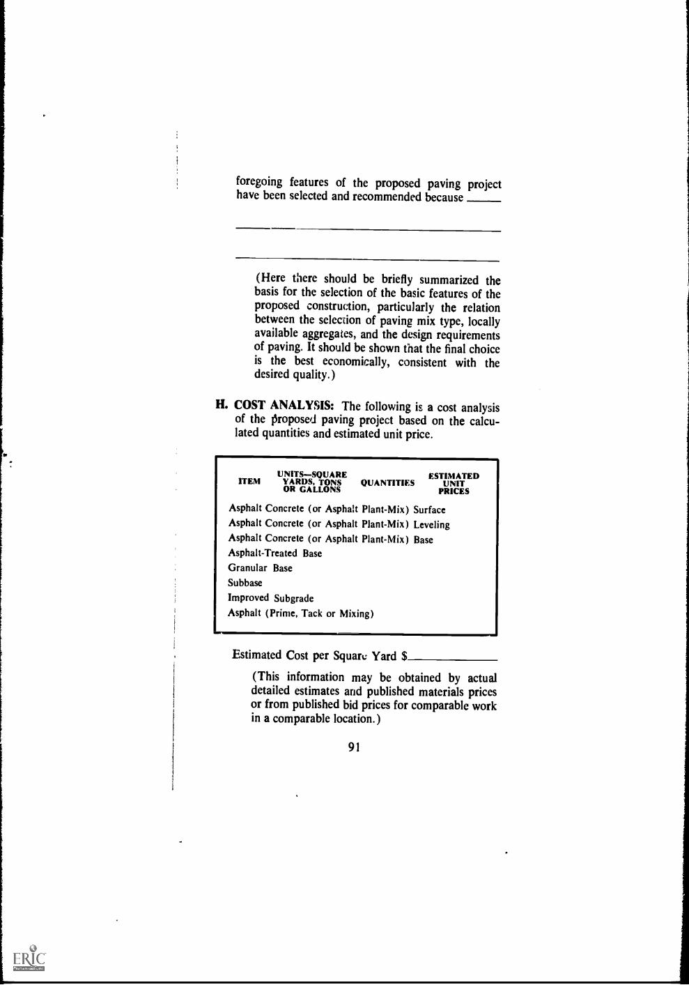
1
I
foregoing features of the proposed paving projecthave been selected and recommended because
(Here there should be briefly summarized thebasis for the selection of the basic features of theproposed construction, particularly the relationbetween the selection of paving mix type, locallyavailable aggregates, and the design requirementsof paving. It should be shown that the final choiceis the best economically, consistent with thedesired quality.)
H. COST ANALYSIS: The following is a cost analysisof the proposed paving project based on the calcu-lated quantities and estimated unit price.
UNITS-SQUARE ESTIMATEDITEM YARDS, TONS QUANTITIES UNITOR GALLONS PRICES
Asphalt Concrete (or Asphalt Plant-Mix) SurfaceAsphalt Concrete (or Asphalt Plant-Mix) LevelingAsphalt Concrete (or Asphalt Plant-Mix) BaseAsphalt-Treated BaseGranular BaseSubbase
Improved Subgrade
Asphalt (Prime, Tack or Mixing)
Estimated Cost per Squall: Yard $
(This information may be obtained by actualdetailed estimates and published materials pricesor from published bid prices for comparable workin a comparable location.)
91
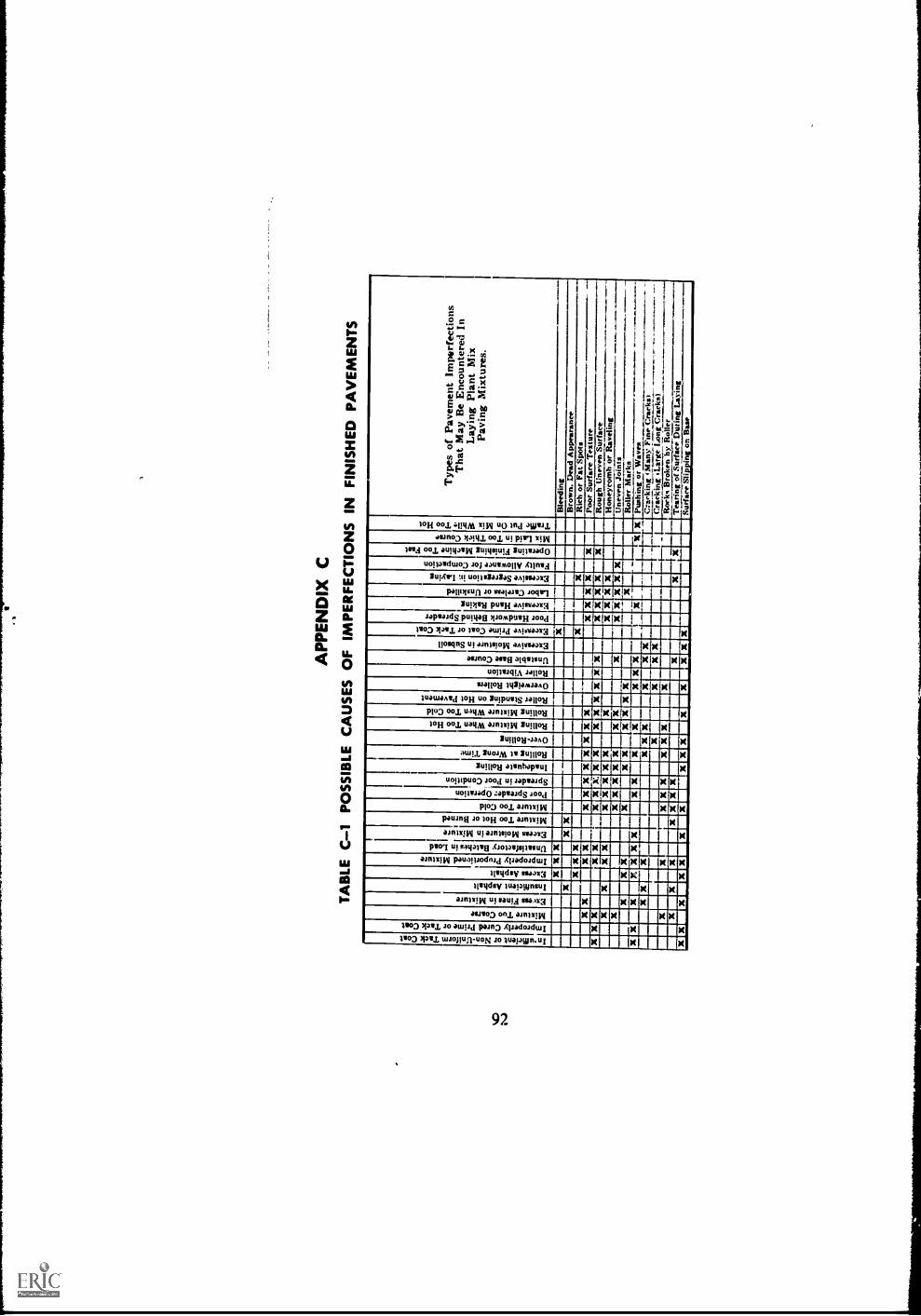
Z6
Ens )1111c11111 In-ufficient or Non-Uniform Tack Coat Improperly Cured Prime or Tack Coat 1 xIMI xi
Mixture Tuo Coarse I :I CIROVIVCIMICII 11101E11:111111121111 CEIRCE11310111CatilE
111111011111:11:11:1C11 1111110111111 Eli CIIIIIMIIIIIMEN
12 s supacpuri
Excess Fines in Mixture Insufficient Asphalt
Excess Asphalt Improperly Proportioned Mixture
Unsatisfactory Batches in Load
Excess Moisture in Mixture Mixture Too Hot or Burned
Mixture Too Cold spinal xi= )1 in Poor Spreader Operation
EcigingErcEing 11111110EMERIn
x iloweacommig iimarillin ICI NE
Spreader in Poor Condition
Inadequate Rolling
Rolling at Wrong Time
Over-Rolling
Rolling Mixture When Too Hot
Econcoug gin iniumommEnn xiirculaimul
0
MU inignici
MN
912 IIMUCCE Min unicningin
inclugg
IIIIMMOIx II poi"'
x x x x x1111
,, x ,,Egiii
Roiling Mixture When Too Cold Roller Standing on Hot Pavement
Overweight Rollers
Roller Vibration Unstable Base Course
Excessive Moisture in Subsoil
Excessive Prime Coat or Tack Coat Poor Handwork Behind Spreader
Excessive Hand Raking
Labor Careless or Unskilled
XX )1 X XIIIII Excessive Segregstion in Laying I:1 Mil Faulty Allowance for Compaction
Operating Finishing Machine Too Fast II X nsilim Mix Laid in Too Thick Course I x 11111111 Trak Put On Mix Whil, Too Hot
z
;Ar.r. ,
z lg.
"I
fr.13."
0 a
vs
2
togginx
, 2 r.... Pi -1 n
;
.5.' '
2
2 1 n R
? ; M
..,7weps.
rol, t ll
7"
cc, ' ...)
5 ;
75 ta
tif 12 p l ).
;
OS
. 1-3
q .<
. S / x 2, eo
E un P PO < ...,--..< in
00 tie Fill g
C Cs CI 4.1 ;*4' Iti
9 CI. a
5

£6
-
Aggregates Too Wet
MMII Nom Inadequate Bunker Separation
ME >II Mang Aggregate Feed Gates Not Properly Set
!MIN > nig Over-Rated Dryer Capacity
Ii22711 II > >
DIE/ ENEN
Dryer Set Too Steep
Improper Dryer Operation
Temp. Indicator Out of Adjustment
Aggregate Temperature Too High
MU>
I INEEDDI II IP'.
ippi a ID=
uNDDI
FWaourInty0suctreeScn oreenpseration
Bin Overflows Not Functioning
Leaky Bins
Segregation of Aggregates in Bins
isneaBleinssoDutueoftoAdOivue:tImoaednitng Screens AC:rgrryeogvaeter I EllEMIlli
11 Emma
El /IN
a
1110
Improper Weighing
Feed of Mineral Filler Not Uniform
Insuffict nt Aggregates in Hot Bins
Improper Weighing Sequence
In ufficient Asphalt
Too Much Asphalt
Faulty Distribution of Asphalt to Aggregat s
111111111111 Asphalt Scales Out of Adjustment
0 el
MU el
1:W1ECCI 0 el 0
I ED
Asphalt Meter Out of Adjustment
Undersize or Oversize Batch
Mixing Time Not Proper
Improperly Set or Worn l'addles
)11 Faulty Dump Gate
0 el II el el el el Asnhalt and Aggregate Feed Not Synchronbed
Occasional Dust Shakedown in Bins
Irregular Plant Operation
Faulty Sampling
XXXXXXXXXI"ZZ.i'> c c
;
r
a c
§ 8
2 2
8 5
o CI
c a
t .4.-dst-tie:vna
-z . esmz-.
CA
c
c.;
3
5 p,
...) - )4
n 2
$ g.
A. E.
w
r
C:, , g:
.-
.11 i
E.
0 Cs = 0
c. -4 2. CM pom
X c cn
n cog = F 4 0
Er '44
,e: ..... . w

APPENDIX D
Sampling Asphalt Products and SpecificationCompliance
NOTE
Material to Supplement "Sampling Bituminous Ma-terials," AASHO Designation T 40 (AST-M Desig-nation D 140)
D.01 NECESSITY FOR STRICT CONTROL PRO-CEDURES.The contributing causes for off-specifica-tion material can be quite numerous, but it appeL:s fromtest results that contamination of the material is theprime culprit. Results point out that the majority of off-specification samples have had flash points too low, pen-etrations too high, viscosities too low, or erratic resultsof the distillation tests. All of these are inherent withsolvent type contamination.
Various laboratories have conducted experimentswhich indicate that one-tenth of one percent of diesel oilin asphalt cements may lower the flash point by asmuch as 50°F. (Pensky-Martens Flash Point Test), and
may increase the penetration by as much as 10 points.In many cases this change is sufficient to cause materialto be out of specification. This one-tenth of one percentamounts to 5 gallons of contaminant in 5,000 gallons ofasphalt, or 0.03 ounces in a quart sample.
To insure quality work, then, it is extremely impor-
tant that contamination of asphalt products be pre-vented, from the time they leave the refinery to theirincorporation in completed work. This importance alsoextends to the matter of samples and sampling proce-dures. Tests carried out to insure compliance with speci-fications are only valuable when they are performed on
94

.
samples which are truly representative of the materialunder consideration.
Most agencies or users require that the supplier fur-nish written certification that asphaltic material meetsthe specifications at the time of loading into the haulingvehicle. Test results of samples taken at the refineryor suppliers storage facility indicate that in virtually allcases, the asphalt has complied with specifications.
Actually in many cases job samples are being taken atpoints as close as possible to the completed work, suchas: ( 1 ) from the distributor tank or its spray nozzles inspraying operations; and (2) from the pumping linesbetween the storage tank and the plant in plant-mixoperations.
The following sections list some of the causes of con-tamination and some suggested precautions to help pre-vent it.
D.02 POSSIBLE CAUSES OF CONTAMINATIONOF ASPHALTIC MATERIAL OR SAMPLES ANDSUGGESTED PRECAUTIONS.
(1) Haulers and Hauling Vehicles. Field observa-tions and studies of test results have indicated that con-tamination of materials during transportation has oc-curred quite frequently and regularly.
POSSIBLE CAUSES
(a) Previous load not compati-ble with material beingloaded.
PRECAUTIONS
Examine the log of loads hauledor check with the supplier todetermine if previous materialhauled is detrimental.If it is, make sure vehicle tanks,unloading lines, and pump areproperly cleaned and drainedbefore being presented for load-ing.Provide a ramp at the unloadingpoint at the plant that will as-sure complete drainage of ve-hicle tank while material is stillfluid.
95
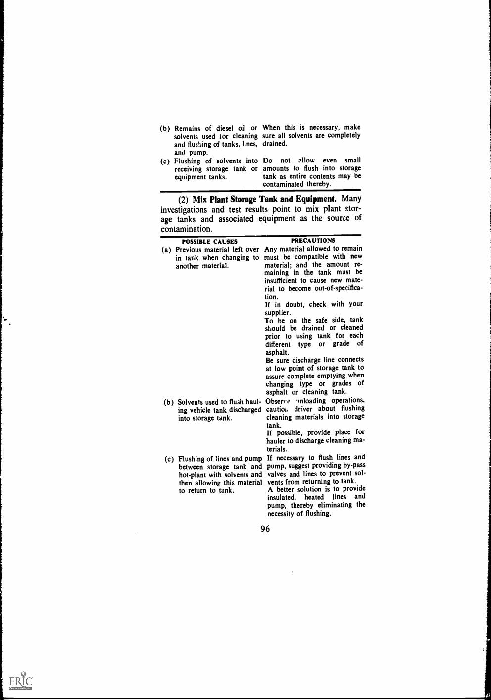
(b) Remains of diesel oil orsolvents used tor cleaningand flushing of tanks, lines,and pump.
(c) Flushing of solvents intoreceiving storage tank orequipment tanks.
When this is necessary, makesure all solvents are completelydrained.
Do not allow even smallamounts to flush into storagetank as entire contents may becontaminated thereby.
(2) Mix Plant Storage Tank and Equipment. Manyinvestigations and test results point to mix plant stor-age tanks and associated equipment as the source ofcontamination.
POSSIBLE CAUSES(a) Previous material left over
in tank when changing toanother material.
(b) Solvents used to flush haul-ing vehicle tank dischargedinto storage tank.
(c) Flushing of lines and pumpbetween storage tank andhot-plant with solvents andthen allowing this materialto return to tank.
PRECAUTIONSAny material allowed to remainmust be compatible with newmaterial; and the amount re-maining in the tank must beinsufficient to cause new mate-rial to become out-of-specifica-tion.If in doubt, check with yoursupplier.To be on the safe side, tankshould be drained or cleanedprior to using tank for eachdifferent type or grade ofasphalt.Be sure discharge line connectsat low point of storage tank toassure complete emptying whenchanging type or grades ofasphalt or cleaning tank.Observe inloading operations,cautich, driver about flushingcleaning materials into storagetank.If possible, provide place forhauler to discharge cleaning ma-terials.If necessary to flush lines andpump, suggest providing by-passvalves and lines to prevent sol-vents from returning to tank.A better solution is to provideinsulated, heated lines andpump, thereby eliminating thenecessity of flushing.
96
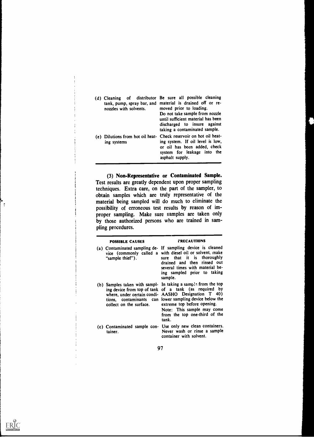
(d) Cleaning of distributor Be sure all possible cleaningtank, pump, spray bar, and material is drained off or re-nozzles with solvents, moved prior to loading.
Do not take sample from nozzleuntil sufficient material has beendischarged to insure againsttaking a contaminated sample.
(e) Dilutions from hot oil heat- Check reservoir on hot oil heat-ing systems ing system. If oil level is low,
or oil has been added, checksystem for leakage into theasphalt supply.
(3) Non-Representative or Contaminated Sample.Test results are greatly dependent upon proper samplingtechniques. Extra care, on the part of the sampler, toobtain samples which are truly representative of thematerial being sampled will do much to eliminate thepossibility of erroneous test results by reason of im-proper sampling. Make sure samples are taken onlyby those authorized persons who are trained in sam-pling procedures.
POSSIBLE CAUSES
(a) Contaminated sampling de-vice (commonly called a"sample thief").
(b) Samples taken with sampl-ing device from top of tankwhere, under certain condi-tions, contaminants cancollect on the surface.
(c) Contaminated sample con-tainer.
rRECAUTIONS
If sampling device is cleanedwith diesel oil or solvent, makesure that it is thoroughlydrained and then rinsed outseveral times with material be-ing sampled prior to takingsample.
In taking a samp;,1 from the topof a tank (as required byAASHO Designation T 40)lower sampling device below theextreme top before opening.Note: This sample may comefrom the top one-third of thetank.
Use only new clean containers.Never wash or rinse a samplecontainer with solvent.
97

(d) Sample contaminated after DO NOT submerge containertaking. in solvent or even wipe outside
of container with solvent-saturated rag.If necessary to clean spilled ma-terial from outside of container,use a clean dry rag.Make sure container lid istightly sealed prior to storageor shipment. Ship to testinglaboratory promptly.
(e) Samples taken from spigot If sampling spigot is in suctionin lines between storage line between tank and pump,tank and hot-plant. this necessitates stopping pump
prior to taking sample. Samplesthus taken are by gravity andonly representative of materiallocalized in the pipe area of thespigot.Rather, the spigot shonid be inlines between pump and returnline discharge, thereby allowingslow withdrawal of materialduring circulation.DO NOT take samp:e whilehauling vehicle is pumping intostorage tank.DO NOT take sample withoutallowing sufficient time for cir-culation and thorough mixingof material.DO drain off sufficient materialthrough spigot prior to takingsample to insure removal of anycontaminant lodged in spigot.DO take sample slowly duringcirculation to be more repre-sentative of material being used.
(f) Samples taken from un- Drain off sufficient materialloading line of hauling ve- through spigot prior to takinghide, sample to insure removal of any
contaminant lodged there.Sample should be taken afterone-third and not more thantwo-thirds of the load has beenremoved. Take sample slowlyto be sure it is representative ofthe material being used.
98

D.03 SAMPLING ASPHALTIC MATERIALSFROM TRUCK TANKS
The following sampling method is based on the use ofthe submerged sampling valve shown in Figure 1. Thissampling valve was selected because, of all the differentsampling devices in use, it most nearly fulfills the fol-lowing criteria:
Virtually foolimOofSafeSelf-draining for cleanlinessSimple and easy to useProvides representativesamplesInexpensive and trouble-free for installationand maintenance
Accessible
Not subject to freezing
Useful both at time ofloading and at destination
Proved with field experience
Applicable to all trucktanks
Figure 1. Submerged Asphalt sampling device.TANK WALL----...... ..---- INSULATION
.* "5 )
EXTEND VALVE STEMWHERE NECESSARYTO CLEAR INSULATION
MOUNT IN LOWER HALF OFTHE BULKHEAD AT LEAST 1'.0" FROM THE SHELL:
REF. No. DESCRIPTION No. REQ.
1 3/4" 'VOGT P.9844 STEEL ANGLE VALVE ORSIMILAR, PANEL MOUNTED 1
2 %" STEEL OR MALL. IRON 900 ELBOW 1
3 3/4" STEEL OR MALL. IRON 450 ELBOW 1
4 ASBESTOS GASKETS SNUG ON THREAD OR WOUNDWITH YARN 4
5 34" 150# SCREWED M. I. LOCKNUT 2
6 3A" x 31/2" ± PARALLEL THREADED STEEL PIPENIPPLE (CUT FROM 3/4" STD. TANK NIPPLE IFOTHERWISE UNOBTAINABLE) 1
7 %" x 3" THREADED STEEL PIPE NIPPLE 2
8 34" MALL. IRON PIPE CAP 1
99

Method of Sampling Asphaloic Materials from Truck Tanks
1. SCOPE
1.1 This method applies to the sampling of fluid as-phaltic materials from transport truck tanks used toconvey material from the shipping point.
1.2 The purpose of this method is to obtain samplesthat will show the true nature and condition of thematerial. The method outlines a procedure for the takingof samples that represent as nearly as possible the ma-terial in the tank.
2. SUMMARY OF METHOD
2.1 The method makes use of a sampling valve in-stalled in an end bulkhead of the truck tank. By properuse of the valve representative samples of the requiredsize can be obtained easily and quickly.
3. SAMPLING VALVE
3.1 This method of sampling is based on the use ofthe submerged sampling valve shown in Figure 1. Thissampling device is constructed entirely of standard pipefittings. The recommended location is the rear bulkheadof the tank. Any significant contamination from previousloads will be included in the sample taken at this location.
4. SAMPLE CONTAINERS
4.1 Containers for asphalt cement samples shall beone-quart triple-seal friction-top cans.
4.2 Containers for liquid asphalt samples except emul-sified asphalt samples shall be one-quart wide-mouthcans with lined screw caps.
4.3 Containers for anionic emulsified asphalt samplesshall be one-gallon wide-mouth jars or bottles made ofglass or plastic.
4.4 Containers for cationic emulsified asphalt samplesshall be one-gallon wide-mouth jars or bottles made ofplastic or wide-mouth cans with lined screw caps.
5. SIZE OF SAMPLES
5.1 The size of samples shall correspond to the re-quired sample containers.
100
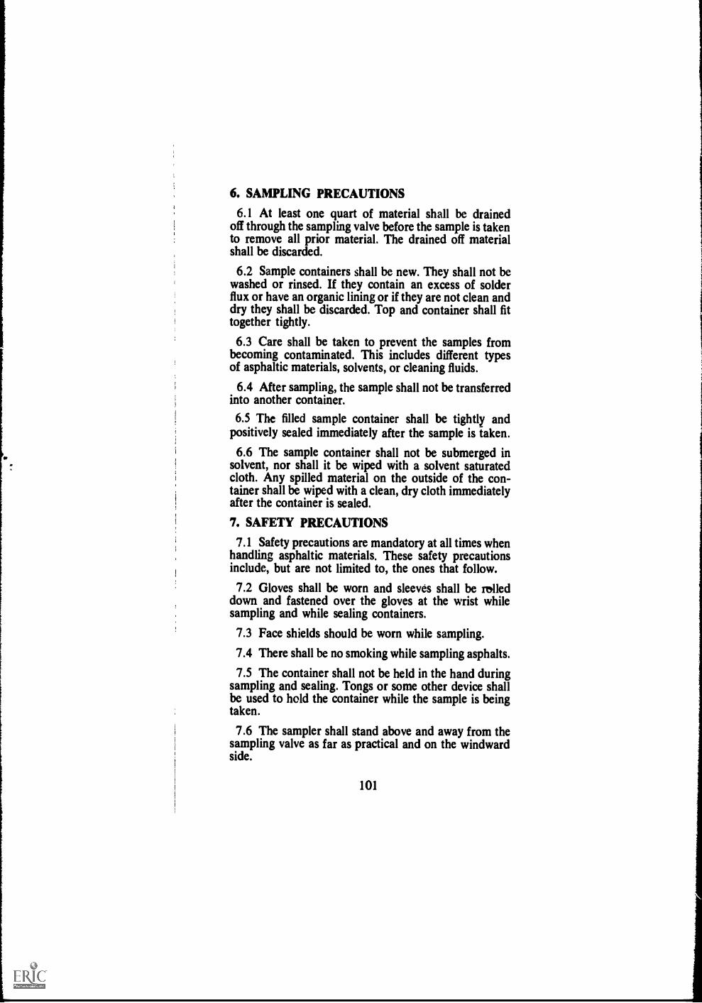
6. SAMPLING PRECAUTIONS
6.1 At least one quart of material shall be drainedoff through the sampling valve before the sample is takento remove all prior material. The drained off materialshall be discarded.
6.2 Sample containers shall be new. They shall not bewashed or rinsed. If they contain an excess of solderflux or have an organic lining or if they are not clean anddry they shall be discarded. Top and container shall fittogether tightly.
6.3 Care shall be taken to prevent the samples frombecoming contaminated. This includes different typesof asphaltic materials, solvents, or cleaning fluids.
6.4 After sampling, the sample shall not be transferredinto another container.
6.5 The filled sample container shall be tightly andpositively sealed immediately after the sample is taken.
6.6 The sample container shall not be submerged insolvent, nor shall it be wiped with a solvent saturatedcloth. Any spilled material on the outside of the con-tainer shall be wiped with a clean, dry cloth immediatelyafter the container is sealed.
7. SAFETY PRECAUTIONS
7.1 Safety precautions are mandatory at all times whenhandling asphaltic materials. These safety precautionsinclude, but are not limited to, the ones that follow.
7.2 Gloves shall be worn and sleeves shall be rolleddown and fastened over the gloves at the wrist whilesampling and while sealing containers.
7.3 Face shields should be worn while sampling.
7.4 There shall be no smoking while sampling asphalts.
7.5 The container shall not be held in the hand duringsampling and sealing. Tongs or some other device shallbe used to hold the container while the sample is beingtaken.
7.6 The sampler shall stand above and away from thesampling valve as far as practical and on the windwardside.
101

7.7 The sample shall be taken slowly to prevent splash-ing of the hot material.
7.8 The container shall be placed on a firm level sur-face to prevent splashing, dropping, or spilling the ma-terial during sealing.
8. SAMPLES
8.1 Two samples of the asphaltic material shall betaken. The sampling shall be done after loading of thetruck tank is complete and before unloading begins.
9. PROTECTION AND PRESERVATION OFSAMPLES
9.1 Immediately after filling, sealing and cleaning (asrequired in paragraph 6.6), the sample containers shallbe properly marked for identification with a wick mark-ing pencil on the containier itself, not on the lid. Linentags also may be used for identification if they can besecurely fastened to the containers in such a manner asto insure that they will not be lost in transit. Linen tagsshall not be attached to containers by using the lids tosecure them.
9.2 Samples of emulsions shall be packaged, labeled,and shipped in such a manner as to protect them fromfreezing.
9.3 All samples should be packaged and shipped tothe laboratory the same day they are taken. The con-tainers, tightly sealed should be packed in absorbentmaterial, such as sawdust, excelsior, or vermiculite, toreduce the probability of damage during shipment.
9.4 Each sample shall be identified with at least thefollowing information:
9.4.1 Shipper's name and bill of lading or loading slipnumber.
9.4.2 Date and time of day sampled.
9.4.3 Sampler's name.
9.4.4 Product grade.
102

NOTE
Three additional methods of samplingasphaltic materials from stationarytanks, from railroad tank cars atorigin, and from railroad tank carsat destination are available uponrequest from the nearest office of TheAsphalt Institute.
103

INDEX
AAggregate
Drying, 56Gradation methods com-
pared, 11-12Grading chart, 10Preparation and handling
at plant, 55-56Samples, 53Sampling and testing, 36Storages 55-56
Airfields, recommended pen-etradon grades, 14
Area to be paved, prepara-tion of, 54
AsphaltControl of application
temperature, 5Preparation for paving, 55Proportioning methods
and mixing, 14-15, 57Asphalt cement
Mixing tempeatures, 7Selecting proper grade,
11, 14Temperature - viscosity
characteristics, 6Asphalt concrete
Definition, 2Construction specifications,
30-70
Asphalt content determina-tion, 15
Asphalt Mixing PlantsControl of mixing time,
57-58Equipment requirements,
39-48Handling of aggregates,
55-56Inspection and control,
52-53Proportioning and mixing,
57
104
Asphalt products, precau-tions against contamina-tion, (Appendix D), 94-102Sampling, 99-102
B
Batch type plants, 39-46Bins, asphalt plant, 41
C
Classification of asphalt pav-ing mixes, 2-4
Climactic conditions, recom-mend ed penetrationgrades, 14
Coarse aggregateDefinition, 2Specifications, 33-34
Coarse graded mixes, 22Cold aggregate feeder, 40Cold-lald plant mix
Definition, 2Using asphalt cement with
liquefier, (Appendix A),80-83
Using liquid asphalt, (Ap-pendix A), 77-79
Compaction, 61-68Density and surface re-
quirements, 67Edges, 65Joints, 63-64Rolling, 65-66Shoulders, 66
Compensation, 68-70
Composition of mixes, 16,20-29, 37-39
Construction specificationsfor asphalt concrete andother plant-mix types, 30-70Compensation, 68-70

Composition of mixes, re-quirements, 37-39
Construction methods, 54-68Compaction, 61-66
Breakdown rolling, 65Edges, 65Finish rolling, 66Longitudinal joints, 64Second rolling, 66Shoulders, 66Transverse joints, 63
Contrcl of mixing time,57
Density and surface re-quirements, 67-68
Preparation ofArea to be paved, 34Paving asphalt. $5
and hem:ling of ag-gregates, 55
Proportioning and mix-ing, 57
Spreading and finishing,58-61
Transportation of mix,58
Weather limitations, 54Description, 30Equipment, 39-52Inspection and control of
asphalt mixing plants,52-53
Materials and tests, 32-37Continuous mixing plants,
special requirements, 46-48
Control of asphalt applica-tion temperature, 5
Curbing, recommended pen-etration grades, 14
Curbs, Gutters, painting of,63
D
Dena graded mixes, com-position, 23
105
Density and surface require-ments, 67
Distributors, 50Dryer, 40Driveways, recommended
penetration grades, 14Dust collector, 42
EEdges, compaction, 65
Emulsified asphalt plant mix-tures, (Appendix A), TableA-1, 78-79
Engineering survey and anal-ysis or Proiectt 8
EquipmentAsphalt plants, 39-48Asphalt sampling device,
(Appendix D), 99-102Distributors, 50Field testing laboratory, 52Hand tools, 52Haul trucks, 51Pavers and laydown ma-
chines, 48Rollers, 49-50Truck scales, 51
Equipments, special require-ments forBatch type plants, 43-46Continuous mix plant% 46-
48F
Field testing laboratory, 52Fine aggregate
Definition, 2Specifications, 35
Fine paded mixes, 24Fine sheet mixes, 27Finished pavement imperfec-
tions, possible caws (Ap-pendix C), 92
Foreword, v

H
Hand spreading, 60Hand tools, 52Haul trucks, 51Highways, recommended
penetration grades, 14Hot-laid plant mix
Definition, 2Using liquid asphalt (Ap-
pendix A), 78; TableA-2, 81
Hot-mix construction speci-fications, 30-70
I
Inspection and control ofasphalt mixing plant, 52
JJob-mix formula, 53
L
Laboratory design methodssuitability of, Table 11-3,17
Leveling course, 54Liquid asphalt plant mixes
(Appendix A), 73-83Longitudinal joints, 64
M
Macadam mix, 20Materials, approval of, 32Mineral dust, 2, 36Mineral filler, 35Mix design method, 16
Suggested criteria for testlimits, Table 11-4, 19
Suitability of laboratorydesign methods, 17
Mix types, definitions, 1-2Mixes, composition of, 16,
20-29Compilation of, 28
106
MixingTemperatures for asphalt
cements, 7Temperatures for plant
mixing, 5Time and proportioning,
57-58
Motor grader, 60
0Open-graded mixes, 21
P
Parking lots, recommendedpenetration grades, 14
Passing-Retained specifica-tion transformed to "totalpercent passing," a proce-dure for, Table II-1, 12
Pavers and laydown ma-chines, 48
Paving mixture deficiencies,possible causes of (Appen-dix C), 93
Plant-mix pavements usingliquid asphalts, 73-83 (Ap-pendix A)Cold-laid using liquid as-
phalt, 77Suggested composition,
Table A-1, 78-79Cold-laid using asphalt ce-
ment with a liquefier,80Suggested composition
of, Table A-3, 82-83Hot-laid using liquid as-
phalt, 78-80Suggested composition
and use, Table A-2,81
General, 73Mix design procedures,
75-76
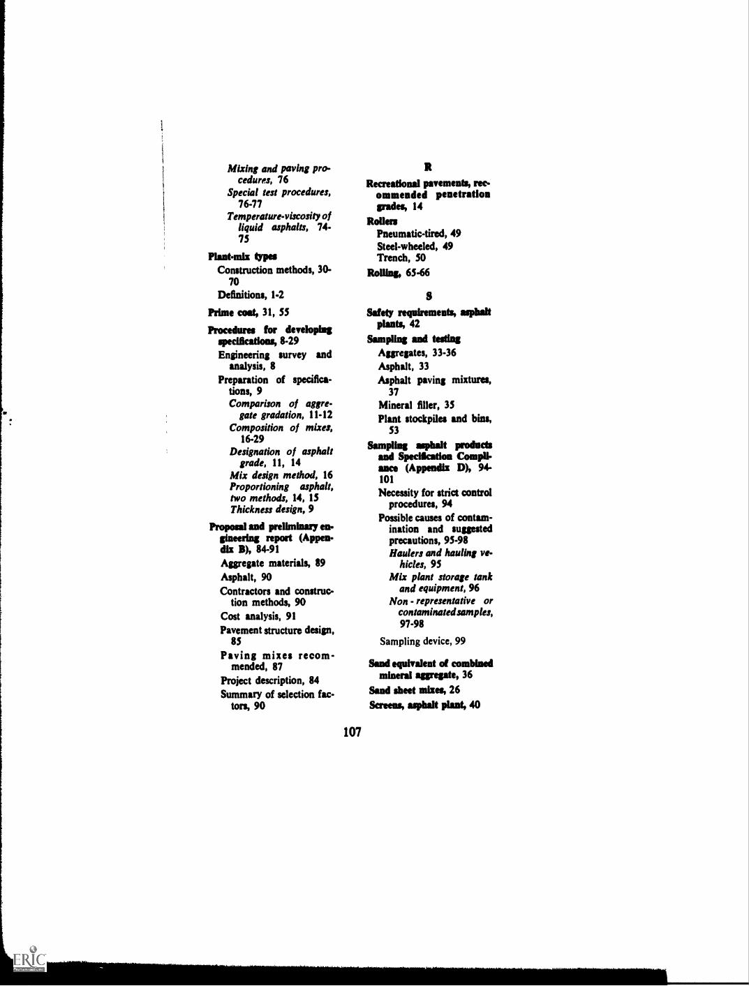
1
1
1
Mixing and paving pro-cedures, 76
Special test procedures,76-77
Temperature-viscosity ofliquid asphalts, 74-75
Plant-mix typesConstruction methods, 30-
70Definitions, 1-2
Prime cost, 31, SS
Procedures for developingspecifications, 8-29Engineering survey and
analysis, 8Preparation of specifica-
tions, 9Comparison of aggre-
gate gradation, 11-12Composition of mixes,
16-29Designation of asphalt
grade, 11, 14Mix design method, 16Proportioning asphalt,two methods, 14, 13
Thickness design, 9
Proposal and preliminary en-gineering report (Appen-dix B), 84-91Aggregate materials, 89Asphalt, 90Contractors and construc-
tion methods, 90Cost analysis, 91Pavement structure design,
85
Paving mixes recom-mended, 87
Project description, 84Summary of selection fac-
tors, 90
107
R
Recreational pavements, rec-ommended penetrationgrades, 14
RollersPneumatic-tired, 49Steel-wheeled, 49Trench, 50
Rolling, 65-66
S
Safety requirements, asphaltplants, 42
Sampling and testingAggregates, 33-36Asphalt, 33Asphalt paving mixtures,
37
Mineral filler, 35Plant stockpiles and bins,
53
Sampling asphalt productsand Specification Comp II-ance (Appendix D), 94-101
Necessity for strict controlprocedures, 94
Possible causes of contam-ination and suggestedprecautions, 95-98Haulers and hauling ve-
hicles, 95Mix plant storage tank
and equipment, 96Non - representative or
contaminated samples,97-98
Sampling device, 99
Sand equivalent of combinedmineral aggregate, 36
Sand sheet mixes, 26Screens, asphalt plant, 40

Sealing surface, 63Shoulders, compaction of,
66
Skip-graded mixesComposition. 29Definition. 18-19
Specification compliance andprecautions against con-taminating asphalt prod-ucts (Appendix D), 94-101
SpecificationsPreparation of. 9Procedures for developing.
8-29
Spreading and finishingHand spreading. 60Mechanical spreaders. 59Motor graders. 60
Stockpile plant mixtures (Ap-pendix A), Table A-1, 78-79
Stockpiling aggregates, 55-56
Stone sheet mixes, 25Straight-edge, 67Streets, recommended pene-
tration grades, 14Surface requirements, finished
pavement, 67
TTack wat, 31, 55Temperature of asphalt ap-
plication, control of, 5
Temperature-viscosity char-acteristics of three as-phalts, 6
Test methods
Asphaltic materials, 33Asphalt paving mixes. 37Mineral aggregates. 36
Thermometric equipment, 42
Thickness
Control. 67Design, 9
"Total percent passing"method conversion, II
Transportation of mix, 58
Transverse joints, 63
Truck scalc5, 51
V
V isco ,iti vs Temperature forasplmlts, 5. 6, 32
V.M.A.-relationship betweenminimum VMA and nom-inal maximum particlesize of aggregate for com-pacted dense-graded pav-ing mixtures, Figure 11-2,18
W
Weather limitations for hotmixes, 54
108
THE ASPHALT INSTITUTEEXECUTIVE OFFICES AND LABORATORIES
Asphalt Institute Building
College Park, Maryland 20740
MEMBERS OF THE ASPHALT INSTITUTE(As of November 1, 1966)
The Asphalt Institute is an international, nonprofit association sponsoredby members of the petroleum asphalt industry to serve both users andproducers of asphaltic materials through programs of engineelingservice, research and education. Membership is limited to refiners ofasphalt from crude petroleum. Institute members provide qualityproducts and advocate quality construction and timely maintenance.
ALLIED MATERIALS CORPORATIONOklahoma City
AMERICAN OIL COMPANYChicago
APCO OIL CORPORATIONOklahoma City
ASHLAND OIL & REFINING COMPANYAshland, Kentucky
ATLANTIC RICHFIELD COMPANYAtlantic Division--PhiladelphiaRichfield DivisionLos Angeles
BRITISH AMERICAN OIL COMPANY LTD.Toronto, Ontario, Canada
BP CANADA LIMITEDMontreal, Quebec, Canada
BRITISH PETROLEUM COMPANY LTD.London, England
BYERLYTE COMPANY OF KOPPERS COMPANY, INC.Cleveland
CANADIAN PETROFINA LIMITEDMontreal, Quebec, Canada
CHAMPLIN PRITOLEUM COMPANYFort Worth, Te,:as
CHEVRON ASPHALT COMPANYSan Francisco and Baltimore
CITIES SERVICE OIL COMPANYTulsa
109

COMPANIA ESPANOLA DE PETROLEOS, S.A.Madrid, Spain
CONTINENTAL OIL COMPANYHouston
DOUGLAS OIL COMPANY OF CALIFORNIALos Angeles
EDGINGTON OIL REFINERIES, INC.Long Beach, California
ESSO STANDARD EASTERN, INC.New York
FARMERS UNION CENTRAL EXCHANGE, INC.Laurel, Montana
GOLDEN BEAR OIL COMPANYA Division of Witco Chemical Company, Inc.
Los Angeles
GREAT NORTHERN OIL COMPANYSt. Paul
Industrial Asphalt, Inc., Agent forGULF OIL CORPORATION
Los Angeles
HUMBLE OIL & REFINING COMPANYHouston and New York
HUNT OIL COMPANYDallas
HUSKY OIL CANADA LTD.Calgary, Alberta, Canada
HUSKY OIL COMPANYCody, Wy ming
IMPERIAL OIL LIMITEDToronto, Ontario, Canada
KERR-McGEE CORPORATIONOklahoma City
LEONARD REFINERIES, INC.Alma, Michigan
LION OIL COMPANYHydrocarbons Division, Monsanto Company
El Dorado, ArkansasMACMILLAN RING-FREE OIL CO., INC.
New York and El Dorado, Ark.
MARATHON OIL COMPANYFind lui, Ohio
MOBI: OIL CORPORATIONNew York
MOBIL OIL CORPORATIONInternational DivisionNew York
110

MURPHY OIL CORPORATIONEl Dorado, Arkansas
NESTE OYHelsinki, Finland
NEWHALL REFINING CO., INC.Newhall, California
NORTHWESTERN REFINING COMPANYSt. Paul Park, Minnesota
AB NYNAS-PETROLEUMNynashamn, Sweden
PAZ OIL COMPANY LIMITEDHaifa, Israel
PHILLIPS PETROLEUM COMPANYBartlesville, Oklahoma
RAFFINERIE BELGE DE PETROLES, S.A.Antwerp, Belgium
SHELL CANADA LIMITEDToronto, Ontario, Canada
SHELL INTERNATIONAL PETROLEUM CO., LTD.London, England
SHELL OIL COMPANYNew York and San Francisco
SINCLAIR REFINING COMPANYNew York
SOUTHLAND OIL COMPANYYazoo City, Mississippi
STANDARD OIL COMPANYOF BRITISH COLUMBIA, LTD.
Vancouver, B.C., Canada
THE STANDARD OIL COMPANY(An Ohio Corporation)
Cleveland
SUN OIL COMPANYPhiladelphia
SUNRAY DX OIL COMPANYTulsa
UNION OIL COMPANY OF CALIFORNIALos Angeles
U. S. OIL AND REFINING COMPANYLos Angeles
WITCO CHEMICAL COMPANY, INC.Pionr Products Division
New York
CONTRIBUTOR
ENVOY PETROLEUM CO.Long Beach, California
111

INSTITUTE ENGINEERING OFFICES
(As of November 1, 1966)
EASTERN DIVISION
WASHINGTON, D.C. 20006-1901 PennsylvaniaAve., N.W.
Connecticut, Delaware, District of Columbia,Kentucky, Maine, Maryland, Massachusetts,New Hampshire, New Jersey, New York,Ohio, Pennsylvania, Rhode Island, Vermont,Virginia, West Virginia
BOSTON, MASS.(Address: 599 North Ave.,Wakefield 01880)
Connecticut, Maine, Massachusetts, NewHampshire, Rhode Island, Vermont
ALBANY, N. Y. 12206-50 Colvin Ave.New York State (except New York City, West-chester County and Long Island)
NEW YORK, N. Y. 10020-1270 Ave. of theAmericas
New York City, Westchester County, LongIsland, New Jersey
HARRISBURG, PA. 17102-800 N. Second St.Pennsylvania
RICHMOND, VA. 23219Travelers Bldg.Virginia
COLUMBUS, OHIO 43215-50 W. Brood St.Ohio
LOUISVILLE, KY. 40207-4050 Westport RoadKentucky, West Virginia
SOUTHERN DIVISION
NEW ORLEANS, LA. 70130John Hancock Bldg.Alabama, Arkansas, Florida, Georgia,Louisiana, Mississippi, New Mexico, NorthCarolina, Oklahoma, South Carolina, Ten-nessee, Texas
AUSTIN, TEXAS 78701Perry-Brooks Bldg.Texas
OKLAHOMA CITY, OKLA. 73102Kermac Bldg,Arkansas, Oklahoma, Northern Texas
SANTA FE, N. MEX. 87501-10 Radio PlazaNew Mexico, Western Texas
MONTGOMERY, ALA. 36104-79 Commerce St.Alabama, Tennessee
ATLANTA, GA. 30326-3384 Peachtree RoadGeorgia
TALLAHASSEE, FLA. 32303Tallahassee Bldg.Florida
RALEIGH, N. C. 27605-2016 Cameron St.North Carolina, South Carolina
112

NORTHERN DIVISION
ST. PAUL, MINN. 55104-276 N. Snelling Ave.Colorado, Idaho, Illinois, Indiana, Iowa,
Kansas, Michigan, Minnesota, Missouri,
Montana, Nebraska, North Dakota, SouthDakota, Utah, Wisconsin, Wyoming
EAST LANSING, MICH. 41823-1019 TrowbridgeRoad
Indiana, Michigan
INDIANAPOLIS, IND. 46205-4165 Millersville
RoadIndiana
SPRINGFIELD, ILL. 62703-2606 S. Sixth St.Illinois (except Chicago), St. Louis County,
Missouri
CHICAGO. ILL. 60639-6261 W. Grand Ave.Wisconsin, Metropolitan Chicago
MADISON, WISC. 53711-4333 Nakoma Rd. f.Wisconsin
KANSAS CITY, MO. 64112-612 W. 47th St.
Kansas, Missouri (except St. Louis Co.), )
Nebraska, North Dakota, South Dakota
JEFFERSON CITY, MO. 65101-616 HowardMissouri (except St. Louis Co.)
OMAHA, NEBR. 61132-6901 Dodge St.
NebraskaBISMARCK, N. DAK. 58501-420 N. Fourth St.
North Dakota, South Dakota
DENVER, COLO. 10215-1401 SaulsburyColorado, Utah, Wyoming
HELENA, MONTANA 59601Power Block
Idaho, Montana
PACIFIC COAST DIVISION
St.
ci
BERKELEY, CALIF. 94710-110 University Ave.
Alaska, Arizona, California, Hawaii, Nevada,
Oregon, Washington
LOS ANGELES, CALIF. 90017-1709 W. Ilth St.
Southern CaliforniaSACRAMENTO, CALIF. 95814Forum Bldg.
Central and Northern California, Nevada
PHOENIX, ARIZ, 15016-3625 N. 16th St.
Arizona
PORTLAND, ORE. 97225-4475 S.W. Scholl:
Ferry Rd.OLYMPIA, WASH. 98502-120 Union Avenue
BuildingAlaska, Washington
113
Printed in U.S.A.
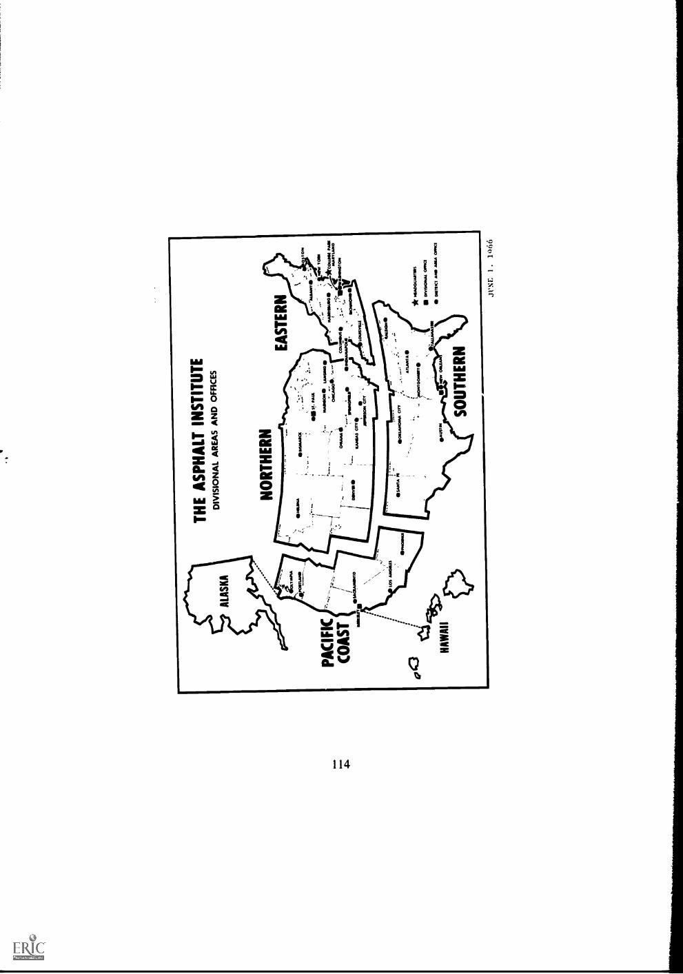
TH
E A
SP
HA
LT IN
ST
ITU
TE
DIV
ISIO
NA
L A
RE
AS
AN
D O
FF
ICE
S
NO
RT
HE
RN
EA
ST
ER
N01
4.1N
A _
PA
CIF
IC
...
'waw
a.,w
...::-
-,:
0 to
ot+
.., :
OS
s!.
muL
wIm
mun
e ,
hosw
ow v
amoo
s--
,w
ww
ansu
eo ./
*cou
rse
mot
owcw
oc"
,--
+
ireA
VA
NLA
NO
OM
AH
A:
CO
SU
NIU
tSA
SW
WIS
ION
*7 .s
ow.2
*.ra
d,w
iwuw
ers
-..
VN
'
tow
evan
""
CO
AS
T/
Los
mai
n
KA
NG
AS
OT
TO i
AM
NO
N C
ITY
oto
/S>
HA
WA
II
* w
iww
ww
ww
ww
s
onw
s.ow
aL w
ows
ww
s A
ND
AM
A O
ffIC
I
SO
UT
HE
RN
JUN
E1
.10
66

SOME IMPORTANT TECHNICALPUBLICATIONS OF THE ASPHALT INSTITUTE
June 1964
Specification Series
Specifications and Construction Methods for Asphalt Con-crete and Other Plant-Mix Types (55-1)
Specifications for Asphalt Cements and Liquid Asphalt(55-2)
Specifications and Construction Methods for Asphalt Curbsand Gutters ISS-31
Manual Series
Thickness DesignAsphalt Pavement Structures for High-ways and Streets (MS-1)
Mix Design Methods for Asphalt Concrete and other Hot-Mix Types (MS-2)
Asphalt Plant Manual IMS-31The Asphalt Handbook 1MS-41
Introduction to Asphalt IMS-51, (Chapters I-IV of the AsphaltHandbook)
Asphalt Pocketbook of Useful Information 1MS-61, (ChapterXV of the Asphalt Handbook)
Asphalt Mulch Treatment (MS7)Asphalt Paving Manual (MS-8)Asphalt for Off-Street Paving and Play Areas (MS-9)Soil Manual for Design of Asphalt Pavement Structures
MS10)Asphalt Pavements for Airports (MS-11)Asphalt in Hydraulic Structures (MS-12)Asphalt Surface Treatments and Asphalt Penetration Mac-
adam (MS-13)Asphalt Mixed-in-Place (Road-Mix) Manual (MS-14)
Copies of these and other Asphalt Institute publications are availableat any Institute field engineering office listed in the end papers,or at Institute Headquarters office at College Pork, Maryland.
115