document resume ed 223 901 ce 034 541 - eric resume ed 223 901 ce 034 541 title basic principles of...
TRANSCRIPT
DOCUMENT RESUME
ED 223 901 CE 034 541
TITLE Basic Principles of Marine Diesel.Engines, 8-2.Military Curriculum Materials for Vocational andTechnical Education.
INSTITUTION Army Transportation School, Fort Eustic, VA.; OhioState Univ., Columbus. National Center for Researchin Vocational Edudation.
SPONS AGENCY Office of Education (DHEW), Washington, D.C.PUB DATE 78NOTE 110p.PUB TYPE Guides - Classroom Use Materials (For Learner)
(051)
EDRS PRICEDESCRIPTORS
IDENTIFIERS
ABSTRACT
MF01/PC05 Plus Postage.Behavioral Objectives; *Diesel Engines;Individualized Instruction; Learning Activities;*Mechanics (Process); Pacing; PostsecondaryEducation; Secondary Education; Tests; Textbooks;*Trade and Industrial Education*Marine Equipment; Military Curriculum Project
This volume of student materials for asecondary/postsecondary level course in principles of marine dieselengines is,one of a number of.military-developed curriculum packagesselected for adaptation to vocational instruction and curriculumdevelopment in a civilian setting. The purpose of the individualized,self-paced course is to acquaint students with the operating cyclesand systems that make ,up a diesel engine. It provides theory that isuseful in laboratory and on-the-job learning experiences. The courseis divided into two lessons: Diesel Engine Construction, Principles,and Structural Parts; and Valve Gear, Fuel Injection, and Governors.These materials are included: the reference text, "Basic Principlesof Marine Diesel Engines" (five chapters and an appended glossary);and a student'workbook that details lesson objectives, readingassignments from the text, review exercises, and review exerciseanswer keys. A course examination is included, but no answers areprovided. (YLB)
***********************************************************************Reproductions supplied by EDRS are the best that can be made *
from the original document.***********************************************************************
KELITAWCURRICULLIMMERIA12
The military-developed curriculum materials in this course
package were selected by the National tenter for ReSearch in
Vocational Education Military Curriculum Pr8ject for dissem-
ination to the six regional,Curriculum _Coordination Centers and
other instructional materials.agencies. The purpose of
disseminating these courses was to make curriculum materials
. developed by the military more accessible to vocational
educators in the civilian setting.
The course material's were acquired, evaluated by project
staff and practitioners in the field, and prepared for
dissemination. Materials which were specific to the iilitary
were deleted, copyrightedmaterials were either omitted or appro-
val for their use was obtained. These course packages contain
curriculum resource materialS which can oe adapted to support
vocational instruction and curriculum development.
'The National_CenterMission Statement
. . . . . .rocir-C-cc Ir-, ,... e
.
The National Center for Research inVocational Education's mission is to increasethe ability of diverse agencies, institutions,and organizations to 'solve educational prob-Jems relating to individual career planning,preparation, and progression. The NationalCenter fulfills its mission tiy:
Generating knowledge through research
Developing educational programs andproducts
Evaluating individual program needsand outcomes
Installing educational programs and .
products
Operating information systems andservices
4
Conducting leadership,development andIraining programs
FOR FURTHER INFORMATION ABOUTMilitary Curriculum Materials
WRITE OR CALLProgram Information Of lice ,
The National Center for' Research in VocationalEducation
The Ohio State University1960 Kenny Road, Columbus, Ohio 4310Telephone: 614/486.3655 or Toll Eree 800/
8484815 within the continental U.S.except Ohio)
C
Military CurriculumMaterials for
Vocational andTechnical Education
tt
1/4.=)
6j.
I f'1
g
c"I
I
.1
VO.Y.
-v.
tt***4 P1I Of
t'11111.4tts:i(041,5,41
infarinntion and'ReldStAvices Divi5fon
The l!alionil Cenler for flesearchin Vocltional Education
c,
'igettl1'fle j 4,0 `, 0:18
I 1Y"i'$'140q1
5

MilitaryCurriculum MaterialsDissemination Is .,_ .
,1....a.-.1 I. .4. r.........11...........
1,
-____...1
an activity to increase the accessibility ofmilitary developed curriculum materials tovoeattonal and technical educators.
This project, funded by the U.S. Office ofEducation, includes the identification and
* acquisition of curriculum materials in prin.!,
form from the Coast Guard, Air Force,Army, Marine Corps and Navy.
Access to military curriculum mateiials isprovided through a "Joint, Memorandum of .
Understanding",between the U.S. Of fice of '
Education and the Department of Defense.,
The acquired materials are reviewed by staff`and subject matter specialists, and coursesdeemed applicable to vocational and tech-nical education, are selected for dissemination.
The National Center for Research inVocational Education is the U.S. Office ofEducation's designated representative toacquire the materials and conduct the projectactivities.
Project Staff:
Wesley E. Budke, Ph.Di, DirectorNational Center Clearinghouse
Shirley A. Chase, Ph.D.Project Director
,
0_,,, 6,
,
0
What MaterialsAre Available?
One*hundred twenty courses on microfiche(thirteen in paper fOrm) and descriptions ofeach have been provided to the vocational
, Curriculan Coordination Centers and otherinstructional materials agencies for dissemi-nation.
Course _materials include programmedinstruction, curriculum outlines, instructorguides, student workbooks apd technicai
'manuals.
The 120 courses represent the follOwingsixteen vocational subject areas:
AgricultureAviat ionBuilding &
ConstructionTrades
ClericalOccupations
Communications()hittingElectronicsEngine Mechanics
Food ServiceHealthHeating & AirConditioning
Machine ShopManagement &Supervision
Meteorology &Navigation
4.
PhotographyPublic Service
The number of courses and the subject areasrepresented will expand as additional mate-rials with application to vocational andtechnical education are identified and selectedfor dissemination.
..... ':- .
How Can TheseMaterials Be Obtained?
Contact the Curriculum Coordination Center
in your region for information on obtainingmaterials (e.g., availability and cost). Theywill respond to your request directly or refer
you to an insfructional materials agencycloser to you.
culMICOLum coutilmo 1 WO CEA I ENS
EAST CENTRALRebecca S. Douglass
Director100 North First StreetSpringfield, IL 62777217/782-0759
MIDWESTRober t Pat ton
Director1515 West Sixth Ave.Stillwater, OK 74704405/377 2000
NORTHEASTJoseph F. Kelly, Ph.D
Director225 West State StreetTrenton, NJ 08625609/292.6562 ,
NORTHWEST P
William DanielsDirector'Building 17Airdustrial ParkOlympia, WA 98504206/753-0879
SOUTHEASTJames F. Shill, Ph.D.
DirectorMississippi State
Drawer DXMississippi State, MS 39762
601/325-2510
University
WESTERNLawrenFe F. H. Zane, Ph.D.
Director17,76 University Ave.Honolulu,111 96822808/948.7834
, i

Correspondence Course 8-2
BASIC PRINCIPLES OF MARLNE DIESEL ENGINES
Table of Contents
Course Description Page 1
Basit Principles of Marine Diesel Engines - Page 3Reference Text
Chapter 1 - Diesel Engine Construction andPrinciples
Chapter 2 - Structural Engine Parts
Chapter 3 - Valve Gear
Chapter 4 - Fuel Injection Systems
Chapter 5 - Governors
Appendix II Glossary
Page 7
Page 28
Page 44
Page 54
Page 64
Page 73
Lesson Exercises Page 85
Examination Page 95

BASIC PRINCIPLES OF MARINE DIESEL ENGINES Correspondence Course 8-2
Developed by:
United States Army
Development andRovrow Dates
Unknown
Occupational Ares:
Engine Mechanics
Cost:
$2.25
Print Pages
102
Availability:Military Curriculum Proiect The Centerfor Vocational Education, 1960 KennyRd.. Columbus. OH 43210
Suggostod Background
None
Torso Audiences
Grades 10-adult
Organization of Massone*:
Reference text; lesson exercises with objectives, lesson assignments, and review exercises; course examination with answers
to the lesson exercises
Typo of Instruction:
IndiVidualized, self-paced
Typo of Materials:
Oa= Principles of Marine Diesel Engines
Lesson 1 Diesel Engine Construction, Principlesand Suuctural Parts
No. of Pages: AverageCompletion Time:
39 Flexible
Lesson 2 Valve Gear, Fuel Injection, and Governors 27 Flexible _.
Lesson Exercises 9, 4
Examination 5
Supplementary Materials Requirod:
None
It71,,ICM4,,x1M11" Expires JUly 1, 1978
Course Description
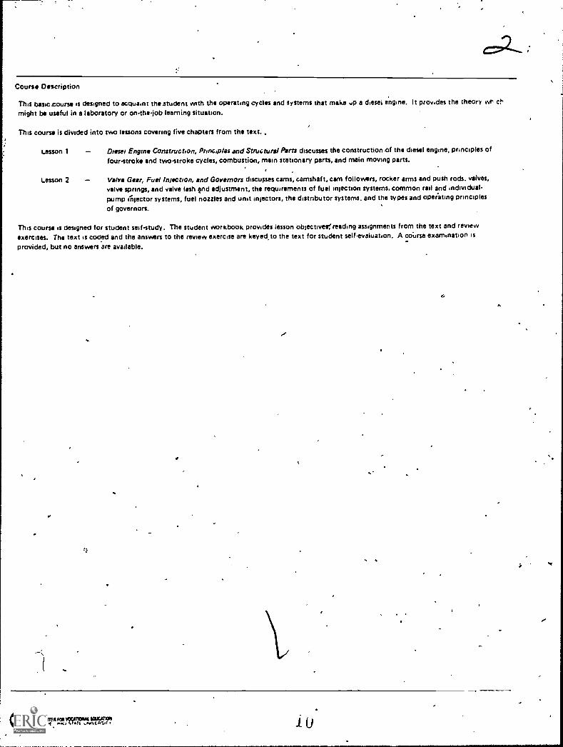
This basic course is designed to acquaint thestudent with the operating cyclu and systems that make up a diesel engine. It provides the theorymight be useful in a laboratory or onthejob learning situation,
This course is divided into two lessons covering five chapters from the text. ,
Lesson 1
Lesson 2
_ Diesel Engine Construction, Principles and Structural Parts discuues the construction of the diesel engine, principles offour-stroke and two-stroke cycles, combustion, main stationary parts, and main moving parts.
Valv Gear, Fuel Injection, and Governors discusses cams, camshaft, cam followers, rocker arms and push rods. valves,valve springs, and valve lash end adjustment, the requirements of fuel injection systems, common rail and individual-pump aijector systems, fuel nozzles and unit injectors, the distributor systems. and the Pipes and opeiating principles
of governors.
This course is designed for student self-study. The student workbook provides lesson objectivelfreading auignmenu from the text and reviewexercises. The text is coded and the answers to the review exercise are keyecito the text for student self-evaluation. A coiese examination is
provided, but no answers are available..
I
q
r
0011eMe Re MOONS SOUGATION 1 0
^

' t. ?:..,7,;.;.,,,:k.r.,,i,,z, ,,,I,,t;.,'°11: 14IN:4111Ar-414it..4ve,,i,L4?.L13.42..:;.11-;:3_.'"+:?'
"ftit,9-4?r, i'-., -.7t. i
. ) ' I . "I 0, .', ,,, ef i 4,,,i''' ;,71,,
l'' ., ,:,. -, ;:.* 0, 41,
:: '1..1,;i' ..i4 '-'f'4C '';;;\gt144tCfel 74' '1:4r,..4.;
4m7",4:, ...., 4- "4.,.,,,--Z-s..1 -4 -.A,' , -',*;-. rt-. I'7,;,...r V, Q,...1.r. ,-,
":,. "-.1`f ;',/,-i ,{144-;*4 /.'.. - ..'; r ,
0f
!
(' .-* 't,
.°
-- -
,* '**,,t/t"" Isd 1 11'4,
' rt I -t"''
,,, LI ..*:?;,. -*. t'...4**: t 4'
'.:;.,.t. i:t' ) ':' ,,
..1- >ritT.P.3,1,=1..,\ ,`"..,.. ::=r;:. -2'4' --r '.:4 ..". ,s.-:..."(lis' A' r''A`'... - I' 4,, m... %
ric.':./",A, el-1Z;:43
r,;'7"' -;,,f4.+;!;,*`4, *.:Srf.-.,:,,-!:,.;-...-....N.,.-e,..b, A- (-51.
:!...7i,..f--:,ip..t.t11.1-1-,..;-,.,,,-.
.,. __....,-.... ..f-,1-,%qt, ....1.},---.--- e..; ,-.1;;;1- * ;s, .74i,
=,; --, ".11- " ". ' .% 4.. *a "? :"-43.7..'"?;
4,
. 4sno........ . -1
,,, , *I..., ,. 4 ...`,''
1.),. ''',...:si . ,. I k..4. ,.._,,,,,.4.,.:,:>-:\ 5;,..,,-.
:?;-...Al. -;,,,, , ,,-',..
.. ,.."....:.. -,..
:.,:, ,.. ( :---,, 2. .-.,...i.r.
:, ,.: I. e; .>-:-- p y.=
.4. ,,;,-i-,, , .... ,--"4..;4.1:, ',1,:-,i,-
}C,'.' i' ; ' 11.
, .
s!::11.!,0,4
. ,V% ,. ,
*- ;".;4'-,i,tn14-. - " ."V.. c..- 2- .
- . ". .( 4 ,r)". ". 2 I
;4''T.d.1.11, . 1', .1 o c' :1'4.44; ; '
, I..
. tic!';r".1 _,.
4514.
; C. !.1 4v7.
r. f f S;,? t';01-V;t:', At: .1
e
.
' /1,-t. -4'Ee`-`1
r T.L
-
:4-.% *
.,,14; "
*.4
. is ''"2'
.CI)
' ettimel
poo4
bi)pri
sc
.
rael. ON% A.
$'4.. "" .>*L 41et
: !4' .% .4 41.:4441:A.* 4:
: '
4:14*, :4-*';14.1%.41.)12?st'A*; ;r4t744*:.#
t.11'...!- t 1 ***'.
.i. ,., ,.,. ,,,...,...t,,,,v.,,,...,
. ,,. .4- ..,.. , ,. ... i...p.......4.;..,}:y- t-r. --tit'sv't,i
''' .Q''::::.:;71;:::::::17:;:::.',t':,,.:5,..1::",::r..'.,.'
ilk;.'.11-A-;, -iv1' ii-,,' It'-'4' . ''.);VO.' .;.1. '7'.-%.4..t. , .f,?r-: 4.3, , ,,,,,-,...,..-,...,.- .4-.1.4.1 ,,,,, . -
IIt !'' '''', '41,-. -1.--,.:4. w, -,7 ,,, i. ...:, , t IS '.6''''..k.._ 141'," ,!,4 ,, 4. ±
i ,S.e 4. .', j 44 # O': 1 ',4:1-... }... $ . 4 .4 4! V 1.4 ,41 ' rm-',.4
,tr4*. t., ,.,,,./..t4i,...E.A.,-,,;.,gai.,,-4.1 :..t. 1 ?''' i I ' 1: .... OW V't 1 ' ...,,'V. ',/ ''.1Z11.(.. .71.'.. ;.-,5 :11:1;" :;1- iti''''..;.:
-"" .'',4' ',. /.. : )S-,''' s:" .74: -4-. - i , -clij;,.......T.....:,. -41X1.11' ;:` -'' 'V ..reil t. :',,.-r. :.. .., S *,'.....'"' ..;.'14,g'f, !'"'.': l'', s 7
J l.......,/ % ' l' I
f`,^)..r' .c.' 0. " :t '''' 4r '4. / n7 1.k'.t.,1,' '''''')':' 94" t* ...- . ')... 1 44 ,, ,-1 14W." , *
. ,,,...
- 1' ;, ,...',..!. ',. ..1 1 t, ,,"/, '),,, ___,- ... --ca ' 1A
)*,/..t.. /.0 .. 6.. p , , .-,, ,, "i.....,..1, i
..... 4. -,,,4 .,1".1. 1i.V.,, < , , , 4.4
., ,,..t.,:4:,... 4 . .:.1-:%,-.!,,v ., .. ,t,, - ,..i.,.... ,;,..,, _ ... r,".i: ",-) . i l'"1..ar..' , 1k... ' . 4k, : .' A ,,'4 It: % 1 -F 4,4 , s. ,- -:
; f" i....,:*"41 t.. lag ..1-er 4. ,14,, .;;t 1.^,{%,4,f; , ,:44-,e, , -, +. .. ,1 , . ;4 ,..., . ,,, , . .); .4' ti ., c 1 7-; ; .-.. : .,,,,,,, , s. ,f. ..rt ti 04 E.g.., ,y..i....,,, . :pi, *1%0 ,F, , ,.11{.; * .'r '., -Ili, 4 -4,I '.i. -*4.' '', ' .."*...L ''ll- '''.4'''''t. -,''' '
", ' -_,..r...' .t.** .1.'' ,..., - .,0 ',:t4:, O."'`.. 1...
14 :: (, ';',`14A. v,!`". / 4:4: 4,':, Z. 0.. 4.4. '4 et ' 4141 ...... '4,, le .,. 4 - <1 . I , .! , t , r. .' . . n . 'i,''' . " 4 . - <j :. "..' :." Tf,,V .' : - '," ' '";' , t 44
i .*, ''', : *4*/".." 1
t T
1!,C... , .
06

CONTENTS
%1
,
, INTRiDDUCnON ..
CHAPTER 1. DIESEL ENGINE CONSTRUC-
S.
TION AND PRINCIPLES . , . .
ection: I. Construction
II. Principles .
CHAPTER 2. STRUCTURAL ENGINE PARTS .
Section I. Main Stationary Parts .
II. Main Moving Parts . .
CHAPTER 3. VALVE GEAR
.4. FUEL INJECTION SYSTEMS ,
5. GOVERNORS
SAPPENDIX I. 'REFERENCES,--\. . . .. .
II. GLOSSARY s 4-
. 1-
INDEX
,re
1 e
-411Plara.
' Paragraph pale
1
3
,
.
1.1
1.2iS 3:
1.1 7
2.1 24
2. 24
2. 2 9
1 I 40
4,1 50'
5.1 60
68
69
. 79
.

4
INTRODUCTION
AZ
The first diekel e gine was built in Germany in 1897. Spark-ignition engines had been built commercially for 37 years. The pos-sibility of compression ignition appears to have been first mentionedby the French scientist N. L. S. Carnot, who in 1824 publishdd hisReflections on the Motive Powei of Heat, in which he discussed thepossibility of igriiting fuel by compress,ing air to one-fourteenth ofits original volume.
Nikolaus Otto built the first engine in which the charge was .com-pressed in the cylinder before burning. This was the engine thatRudolf Diesel undertook to improve when he started experiments thatled to the diesel engine.
After several years of studying the problems involved, Dieselapplied for and was granted a patent in February 1892 under the.title"Working Processes for Internal-pombustion Engines, " and -a secondpaterit, granted a year later', ,that modified the cycle-described.These patents were not for engine designsi' but merely for the thermo-dynamic cycle to be followed by thegases in the engine cylinder.
-
Diesel's first engine.was to run on pulverized coal, but thisproject was dropped foran-oil-burning engine; after several failures,the engine ran in.1897,
The fuel economy of Diesel''s engine proved to be better than thatof any other existing power plant. His engine attracted considerableinterest at an industrial exposition in Munich the following year,where,Adolphus Busch, a U. S. brewer, saw it. Realizing'its poisi-bilities, he purchased a license from Diesel for manufacture and salein the United States and Canada. A diesel engine built for his corn- -pany in 1898 was the first to be placed in regular industrial service.
The first marine installation of a diesel engine was made in 1910,very successfully, and the diesel e'ngine became the predominantpower plant for submarines during World War I.
:yr

t#
This text, divided into five chapters, describes the fundamentalsof marine diesel engines. The first chapter discusses diesel engineconstruction and principles. Structural engine parts are explainedin chapter 2; The remaining three chapters cover valve gear, fuelinjection, and governors respectively.
...
..
r
Q
A.
o
,
,
\I
1
Chapter 1
DIESEL ENGINE CONSTRUCTION,ANDPRINCIPLES
I . I. INTRODUCTION
Diesel engines are found in many different designs depending
upon the type of vessel and its intended use. Although the outside of
engines look different, the internal structure is basically the same.
The first section of this chapter briefly explains the parts of a diesel
engine and the various types and designs of diesel engines. The
second section explains how and why diesel engines operate.
Section I. Construction
1.7. GENERAL
Diesel engines vary greatly in outside appearance, size,
number of cylinders, cylinder arrangement, and details of construc-tion. However, they all have the...same main basic parts which maylook different but perform the same functions. A diesel engine has
very few basic main working parts; the rest of the engine is com-
posed of auxiliary parts which assist the main working parts in their
performance, anci`of..cormecting part.s necessary to hold the working
parts together. The main working parts are the cylinder, ,piston,connecting rod, crankshaft, bearings," and fuel pump and nozzle.
/73Naturally, an engine has'a numbe,r of osier 1:a-rts'without,
which it could not operate, but their functions are more or suti-
ordinate and they are discussed later.
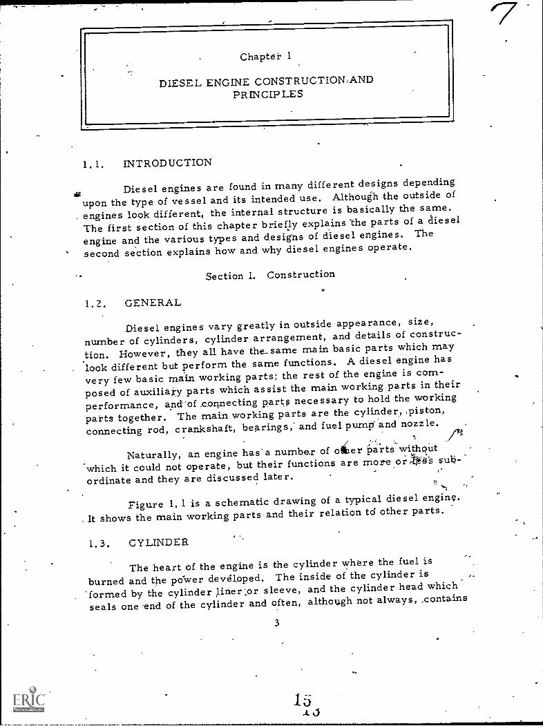
Figure 1.1 is a schematic drawing of a typical diesel enginc.
, It shows the main working parts and their relation td other parts.
I. 3. CYLINDER
The heart of the engine is the cylinder where the fuel is
burned and the po'wer devdloped. The inside of the cylinder is
'formed by the cylinder liner:or sleeve, and the cylinder head which'
seals one 'end of the cylinder and often, although not always, contains
3

1. Cylinder 14. Crankshaft.2. Cylinder liner. 15. Engtnr tram&3 Cylinder head. 16. Cra n Isca
4. Intake valve. 17. Timing chain5. Exhaust valve. sprocket.6. Fuel injector. 18., Timmg chain.7 Fiston 19. Camsha ft.8. Piston rings. 20. Cams9. Wrist or piston pin. 21. Cam ollower.
10- Connecting rod. 22. Push rod11 Crankpin bearing. 23. Rockzr ann.12 Crankmn 24. Valve spring.13. Crank chcck or crank
web.
Figure 1. 1. Schematic Drawingof a Diesel Engine.
1. 6. CRANKSHAFT
the valves to admit fuel and air ndto eliminate the used gases. The'interior diameter of.the- liner is knowknown a's the bore,
. .
1. 4. PISTON
The piston seals the 'otherend of the working space of thecylinder and transmits, to,the out-side, the power developed insidethe cylinder by the burning of thefuel. A gas tight seal between thepiston and the cylinder liner isproduced by piston rings lubricatedwith engine oil. The distance thatthe piston travels from one eild ofthe cylinder to the,other is knownas the stroke.:
1. 5.. CONNECTING ROD
The connecting rod trans-.
mits the reciprocating motion ofthe piston to the continuousLy rotat-ing crankshaft during the powerstroke. One end, the small end ofthe cOnnecting rod or conrod eye,is attached to the wrist pin or pis-ton pin located in the piston; theother, or big end, has a bearingwhich encloses the crankpin.
The crankshaft obtains its rotary motion f r om the pistonthrough the connecting rod and crankpin located between the. crankwebs or crank cheeks. The work of the piston is transmitted to theflywheel to reduce speed fluctuations by storing kinetic energy duringthe periOds when power is developed and giving it back during theother periods.
1. 7. CAMSHAFT
A camshaft is driven from the crankshaft by a chain drive ortiming gears. Through carn followers, push rods, and rocker' arms,
41 6
the intake and exhaust valves are ope.rated by cams on the camshaft., Valve springs close the valves.
le
1. 8. , CRANKCASE,.
A crankcase is constructed to protect the crankshaft, bear-ings, connecting rods, and relp.ted pai.ts; to catch oil escaping from .the bearings of the moving parts; and to provide a reservoir forlubricating oil. If the crankcase is constructed to support the wholeengine, it is called a tied plate.
1. 9: FUEL INJECTION-
Fuel for diesel engines is delivered into the combustion spaceof the cylinderby an injection system consisting of a pump, fuel line,and injector, also called injection or spray nozzle.
1. 10. ENGINE .TYPES
Diesel engines may be divided intt several clasies using dif-ferent bases for the division: operating cycle, cylinder arrangement,piston action, method of fuel injection, and speed, s scribed insubparagraphs a through e.
a. Operating cycles. Diesel engines may be divided into
two groups based on the'number of piston strokes per oycle, in (1)four-stroke-cycle; or for short, four-stroke engine, and (2) two-stroke-cycle, or two-stroke engine. Section.11 explains the meaningof these terms and the difference between these two engire types,
, ,
b. Cylinder arrangement. One of the most common ways toclassify a diesel engine is by its cylinder arrangement. These typesare the in-line, V-arrangement, flat, multiple-engine units, andvertical-shaft, as described in subparagraphs (1) through (5).
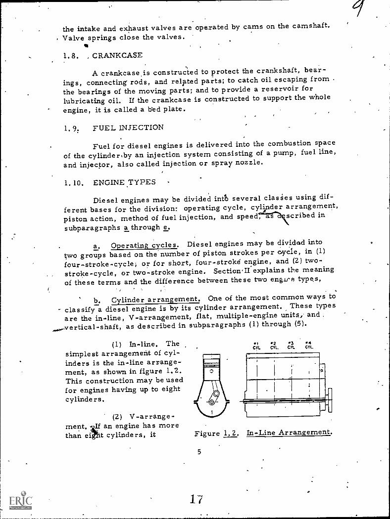
(1) In-line. Thesimplest arrangement of cyl-inders is the in-line arrange-ment, as shown in figure 1.2.This construction may be usedfor engines having up to eightcylinders.
(2) V-arrange-ment. 4-1f an engine has morethan ei t cylinders, it
_
tCYL
.2CYL. CYL
4CYL
Figure 1.2. In-Line Arrangement.
5
17a
sq.
r

becomes difficult to make a sufficiently rigid frame and crankshaftwith an in-line arrangement. The V-arrangement, as illustrated infigure 1.3(a), with two connecting rods attached to each crankpin,
permits reducing the enginelength by one-half, thus mak-ing it much moxe rigid, witha stiff crankshaft. This is acommon arrangement for en-gines with eight to 16 cylinders.Cylinders lying in one planeare called a-bank. In figure1.3(a); the angle "a" between
(b) the banks may vary from 300to 1200, the most common an-gle being between 40° and 75°.
(3) Flat engine. As illustrated in figure 1.3 (b), V -typeengines having 180° between the banks are called flat engines. Thisarrangement is used mostly for trucks and buses.
(4) Multiple-engine units. . To increase the engine powerwithout increasing its bore and stroke, two and four complete 'en-gines, having six or eight cylinders each, are combined in one unitby connecting each engine to the.main drive shaft "5, " as shown infigure 1.4(a) and (b), bymeans of clutches and gearsor clutches and roller chains.Figure 1.4(a) shows a twin-
.. engine; figure 1.4(b),quadruple-engine or quad.
(0)
Figure 1.3. V-Type Engines.
b
Figure lt°4. Multiple-Unit Engines.
(5) Vertical-shaft engine. Arecent development is an,engine withfour connecting rods attached to dnecrankpin, ,as s'hown in figure 1.5. Thefour cylinders are all in the same plane,the crankshaft thus being vertical. Fouirbanks, located one on top of the other andusing one crankshaft with four cranks,form a cOmpact 16-cylinder engine used
Figure 1.5. Top View of in the Navy under the name of the Pan-..
a Pancake cake engine.Engine.
.16

c. Piston action. Diesel engines can also be classified bytheir piston action as explained in subparagraphs (1) through (3).
(1) Single-acting engines use only one end of the cyl-inder and one face of the piston to develop power. The engineS infigures 1.1 through 1.5 are all single-acting.
(2) Double-acting engines use both ends of the cylinderand both faces of the piston to develop power. Double-acting enginesare built only in large and comparatively low-speed units.
(3) Opposed4iston engines have two pistons per cylin-der, driving two crankshafts. The design presents Many advantagesfrom the viewpoint of combustion of the fuel, engine maintenance,and accessibility of all parts, except the lower crankshaft.
d. Fuel injection. Diesel engines are divided into air injec-tion and solid or mechanical-injection 'engines. Chapter 4 discussesthe meaning of these terms and the differences between the two types.
e. Speed. All d'iesel engines can be divided into threeclasses: low-speed, medium-speed, and high-speed engines. Thepresent trend is,away from low- and even medium-speed engines to-ward increasingly higher-speed engines.
1. 11. SUMMARY
The marine diesel-enginev regardlesa of its outward con-figuration, has only a few main basic internal parts. They are thecylinder, piston, connecting rod, crankshaft, camshaft, crankcase,and fuel injection system. Although various auxiliary parts areneeded, the few basic parts remain the same from engine to engine.
Since diesel engines come in many different types, there isa need for a classification system. This is accomplished by fivecategories: operating cycle, cylinder arrangement, piston action,method of fuel injection, and.speed.
Section II. Principles
1;12. GENERAL
As section I explains, a diesel engine operates on`one of twocycle's, either the four-stroke-cycle or the two-stroke-cycle. Thesteps in the four-stroke-cycle are intake, comi)ression, ignition,and exhaust. The steps in the two-stroke cydle are exhaust and
7

/?-
intake, and compression and ignition. This section dovers functionswhich supplement the steps of the four-stroke,and two-stroke engine.They are scavenging, turbulence, supercharging, and timing.
1. 13. FOUR-STROKE-CYCLE EVENTS
A round of events reciirring regularly and in the samesequence is known as a cycle. The cyclicevents in a four-strokediesel engine are, in sequence, (1) filling of the engine cylinder with'fresh air; (2) compression of the air charge to raise its pressureand temperature to that necessary to ignite and burn the fuel effi-ciently; (3) combustion of the fuel and expansion of the hot gases;and (4) emptying the cylinder of the burned gases by exhausting them.When these four events are completed, the cycle is repeated. Wheneach of these events takes place,' roughly speaking, during one strokeof the pistoh, the cycle is called a four-stroke cycle.
The positions of the piston when it is nearest to the cylinderhead and farthest away from it are called top and bottom dead cen-ter, or for short, top and bottom center, indicated by "t. c. " and"b. c. " The reason for this designation is that at these positions theconnecting-rod centerline coincides with the crankt4row centerlineand the piston cannot be moved by gas pressure acting upon its sur-face. The motive force must come from the rotating crank actingthrough the connecting rod.
The four main events are shown diagrammatically in figure1. 6. During the first or suction stroke, figure 1.6(a), the piston (P)moves downward, pulled by the connecting iod (r), the lowe'r,end ofwhich is moved by the crank (C).. The piston motion creates avacuum In the cylinder, ana outside air is drawn or sucked into thecylinder through the intake.valve (i) which opens at about the begin-ning of the suction stroke and stays open until the piston reaches thelower or bottom center (b. c. ).
,1K
When the piston has passed b. c. , the second or compressionstroke begins, figure-A 6(b); the intake valve is closed and the up-ward motion of the piston pushed by the crank and the connecting rodbegins to compress the air charge in the cylinder.
Shortly before the piston reaches top center (t. c.), liquidfuel in a finely atomized spray is admitted into the cylinder contain-ing hot compressed air. The fuel is ignited by the heat of the aircompressed in the cylinder and burns during the first part of thedownward piston stroke. During this downward or third 'stroke,'called working or power stroke, figure 1. 62., the liot gases, whose
8 2u

(o) (b) lc)
OPEN
Figure 1.6. Four-Stroke-Cycle Events.
pressure was considerably increased by the combustion of the fuelcharge, force the piston,downward and expand because of the increas-ing cylinder yolume.
Shortly before the piston reaches the bottom' center, the ex-haust valve (e) opens, figure 1.6d, and the hot products of the combus-tion, haying a relatively high pressure in spite of the previous ex-pansion, begin to rush out through the exhaust ports into the outsideatmosphere. During the following fourth or exhaust stroke,- the pis-ton moves upward, pushed by the crank and conneeting rod, expellingthe remaining products, of combn, until near top center the ex-haust valve is closed, the intake valve is opened, and the whole cyclestarts again. As can be seen, the four strokes require two engine
revolutions. Thus in a four-stroke-cycle engine,, one power strokeis obtained for every.two engine revolutiOns, or the number of powerimpulses per min-Lite are equal to one-half of the rpm of the engine.
,
Actually,the dividing points between the four main events do
not come at the very beginning and end of the corresponding strokes.The differences are smaller in low-speed engines and increase asthe engine speed increases. The intake valve is opened before top
center, 10 to 2-5-crank-angle degrees;--it-is closed_from_ 2,5_to- 4_5crank-angle degrees after bottom center. The fuel injection starts
9
I.
a

some 70 to 260 before t.c. To release the exhaust gases in propertime, the exhaust valve begins to open 300 to 60° before b. c. andclose 100 to 20° after t.c.
1.14. COMPRESSION
The air charge is compressed during the second or compres-sion stroke for two reasons. The first is to increase the thermal oroverall efficiency of the engine by increasing the final temperatureof combustion; this applies to all internal combustion engines, bothof the spark,-ignition as well as the so-called diesel type. Thesecond reason is to raise the temperature of the air charge so muchthat, when the finely atomized fuel is injected into the hot air, thefuel will ignite and begin to burn without any outside source of igni-tion such as the spark plug used in automobile engines.
Compression ratio of an internal combustion'engine is ,theratio of the volume V1, cu. in. , "if the gases in the cylinder with thepiston at bottom center to the voliime V2 of the same gases with thepiston at top center. Compression ratio is designated by r. Com-pression ratio equals volume at bottom center divided by volume attop center or:
r = V1 V2.,
The volume V2 is called the compression or combustionspace. The volume V1 is equal to the sum of the piston displaceMen'tof one cyli:ndefplus the combustion space.
Diesel engines uie compresslon ratios of 12:1 to 19:1. The-oretically, an increase of the compression ratio yaises the thermalefficiency of the engine and lowers its fuel consumption. Hawever,an increase of the compression ratio is accompanied by higher gaspressures and combustion temperatures. This causes increasedstresses and pressures in various engine parts, and to counteractthese ill effects requires stronger, heavier parts and increasesunduly the weight of an engine. Higher temperatures and pressureslso_increase the wear -and tear of an engine and thus decrease its
reliability.
1.15. COMBUSTION
Two distinctly different methods of burning the fuel-in anengine cylinder exist: at a donstant volume apd at a constant pres-sure. Combusti6n at constant volume means/that during combustionthe volume does not change and that all the heat energy developed by
10 22

,
the fuel goes irito an increase of the gas temperature and pressure.Combustion at constant volume also rheans that combustion b'roceedsat such a high rate that the piston has practically no time to moveduring combustion. Such a combustion is obtained when the pistonis passing top center. The advantage of this method of fuel combus-tion is a high thermal efficiency. Its,.disadvantage is a very suddenpressure,increase and resulting Aoisiness of the engine. Such com-bustion is somewhat approached by spark-ignited gasoline engines.
Cornbustion at constant pressure means that during combus-tion the temperature increases at. such a rate that the resulting in-crease of pressure is ju'st enough to counteract the influence of theincreasing-volume and the pressure does not change. The heatenergy developed by the fuel goes partly into an increase of the gastemperature and partly into performing outside work. In the case ofan engin-e with coftstarit-pressure combustion, the fuel is burnedgradually so that the pressure attained at the end of the compressionstroke is maintained during the greater part of the combustion event.Such a combustion was used in the original low-speed, air-injection
.. diesel engine. Its advantage is a smoothly running engine producinga4more even torque because of the extended combustion pressure.However, it is not suitable for high-speed oil engines.
4
High-speed diesel engines of the present operate on a cyclewhich is approximately a combination of the above two methods; part
,,of the fuel is burned raPidly, almost at a constant volume near thetop dead center, and the rest is burned while the piston begins tomove away from top center. However, the pressure does not remainconstarit, but usually increases and then decreases. In general thiscycle resembles more thea constant-volume combustion cycle thanthe cycle of the original diesel engines. Its advantage iS high effi-ciency, with low fuel consumption. Its drawback is in the difficultyof preventing rough and noisy operation of the engine.
1.16. TWO-STROKE-CYCLE EVENTS
A two-stroke cycle is co,mpleted in two strokes, or one revo-lution of the crankshaft, whereas a four-stroke cycle requires tworevolutions. The difference between the two-stroke and four-strokeengine is in the method ok removing the burhed gases and filling thecylinder with 'a fresh charge of air. In a four-stroke engine, theseoperations are performed by the engine piston during the exhaust andintake strokes. In a two-stroke engine, they are- performed near the-b(T)ttom-dead t erite-ir-by-mearrs of z-separate air pump or blower.
.4.
,
11

The compression, com.bustion, and expansion events do notdiffer from those of a four-stroke engine. The filling of the cylinader, called scavenging, with a fresh charge may be explained as fol-lows: when the piston has traveled 80 to 85 percent of its expansionstroke, exhaust vailves e, e, as sheiwn.in figure 1.7, are opened,and the exhaust gases are.released and begin to escape from thecylinder. The piston continues to ,move toward the bottom centerand soon"uncovers ports s, s, through which lightly compressed airbegins to enter the cylinder. The air, havingA a slightly higher pres-sure than the hot gases inthe cylinder, pumps out the hot gasesthrough valves e, e, figure 1. 7(b). This operation is called scaveng-ing. The air admitted is called scavenge air; the air admittanceports, scavenge ports. About the timewhen the piston, on its up-ward stroke, closes ports s, s, the exhaust valves e, e, are alsoclosed, figure 1.7(c), and the compression stroke begins.
(a) (b) Cc)
Figure 1. 7. Scavenging-of a Tw -Stroke-Engine.
The advantage of the two- e gine is the .elimination ofone scavenging and one charging stro e required in a four-stroke-cycle operation. Th'us, the cylinder delivers one power stroke forevery revolution of the engine as. corppared with one power strokefor every two revolutions in a four- troke-.cycle engine. Theoret-ically, if all other conditions such s bore, stroke, speed, and gas
li 24

;
./pressures are equal, a two-stroke-cycle engine should develop twicethe power, of a four-strokte-cy.ple engine. This means also that a two-stroke engine would weigh only one-half as much as a four-strokeengine of the same power and should produce a more even torque.Practical factors prevent the attainment of these ideal figures.
The advantages aro important in ship installations, and,therefore, two-stroke engines'are used in vessels much more thanfour-stroke engines, particularly in larget power units. The disad-vantage of the two-stroke operation is the higher working tempera-ture of the piston and cylinder head because of combustion occurringevery revolution and resulting in distortion of these and related parts.
1.1.7. SCAVENGING METHODS
Figure 1.7 illustrates only one of several methods of cylinderscavenging. In some engines the exhaust gas,es are let out throughports, uncovered by the piston, the same as the scavenge ports (s, s)in figure 1.7. Depending upon the location of the exhaust ports tothat of the scavenge ports, there exist two basically different methodsof scavenging: direct or cross-flow scavenging and loop ocr return-
,flow scavenging, as shown in figures 1.8 and 1. 9.
4
Figure 1. 8. Direct orCross-Flow Scav-engj.ng. Figure I. 9. Return-
Flow orLoop
13
Scaveng-ing.

*V'
In cro-ss-flow scavenging, the piston uncover,s first the ex-haust ports (e, e) and releases the pressure; going down further, thepiston uncovers the scavenge port (b, b) and begins to admit slightlycompressed air whose stream is directed mainly upward, as indi-cated by the arrows, and thus pushes out the exhaust gases throughport. (e, e). Having passed:the dead center, the piston closes firstthe scavenge ports and, soon afterward, the exhaust ports. Thefact that the exhaust _ports are closed after the scavenge ports permitsome of the air charge to escape *from the cylinder. This is a dis-advantage'of this scevenge scheme. However, it has also the de-cided advantage of, simplicity of construction and of maintenance be=cause of the abserice of valves which must be kept tight.
Return-flow or loopLscavenging is similar to-cross-flowscavenging in the sequence of the port opening. However, the direc-tion of air,flow is different, as indiCated by the arrows. Its advan-tage is that*the bulky scavenge-air .and exhaust-gas ports are locatedon one side of the cylinder, thus giving better accessibility. This.scheme is particularly suitable-for double-acting engines, since withthem the Operation.of the exhaust valves for the lower combustionspace becOmes complicated. 'When used for double-acting engines,the scheme is improved by the introduction of rotary exhaust valves.As can be seen in figure. 1.10, during.the release of the exhaustgases, valve (r) is open but it is beingclosed when the piston on the returnstroke coVers the scavenge ports.. Bythis arrangement, the escape of air I -
charge is eliminated during the begin-sting of the compression stroke when the.exhaust ports are not yet covered.Some time after the exhaust ports arecovered by the piston,lite rotary valveis opened, getting it ready for the next L.
cycle. As can be seen from figure 1.10,the length Of the piston is exactly gqualto the length of the stroke to control theexhaust and scavenge events alternatelyby the-upper and lower edges of the pis-ton.
The oppdsted-piston scheme isshown in figure 1.11. The lower pistoncontrols the exhaust ports; the upperone, the scavenge ports. To obtain thehecessary preliminary release of theexhaust gases, or an uncovering of the
1 42
rFigure 1.10. R turn Scav-
e mg in aD u6le -Act-int Engine.
sa.
(a) (b) (c)
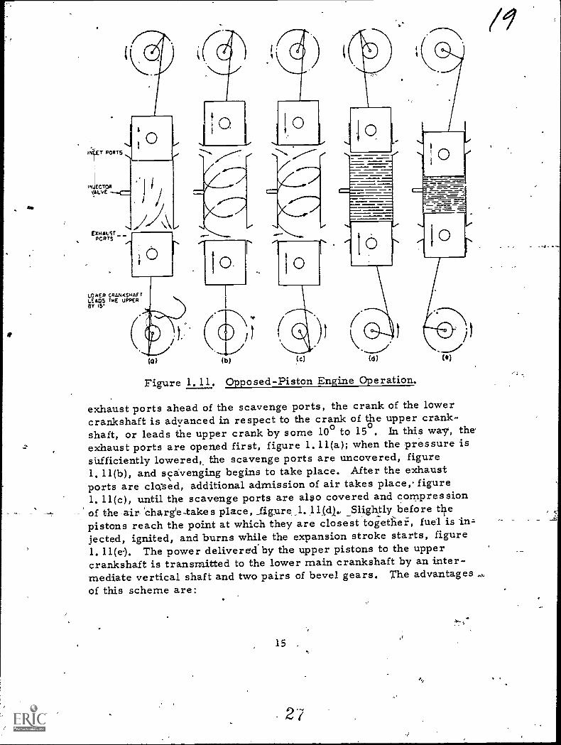
Figure 1.11. Opposed-Piston Engine Operation.
(e)
exhaust ports ahead of the scavenge ports, the crank of the lowercrankshaft is adyanced in respect to the crank of the upper crank-shaft, or leads the upper crank by some 100 to 15o. In this way, theexhaust ports are opened first, figure 1.11(a); when the pressure isshfficiently lowered, the scavenge ports are uncovered, figure1.11(b), and scavenging begins to take place. After the exhaustports are cloed, additional admission of air takes place, figure1.11(c), until the scavenge ports are also covered and compressionof the air-lcharg'e-takes place, _figure J. 11(.31., _Slightly before thepistons reach the point at which they are closest together, fuel is in=jected, ignited, and burns while the expansion stroke starts, figure1.11(e). The power delivered by the upper pistons to the uppercrankshaft is transmitted to the lower main crankshaft by an inter-mediate vertical shaft and two pairs of bevel gears. The advantagesof this scheme are:
15 ,
27

a. . Efficient scavenging of the cylinder and hence greaterpower is developed.
b. Absence of valves and valve-operating gears.
c. Absence of cylinder heacis which are complicated cast-ings and a source of trouble in engine operation.
d. Good accessibility for the inspection and repair of mostparts, except of the lower crankshaft.
The two scavenge schemes, shown in figures 1.7 and.1.11, are also classified as uniflow scavenging. In both cases theexhaust gases and scavenging air are flowing in the same directionwith less chance for formation of turbulences which are unavoidablewith cross- and return-flow scavenging.
1.18. TURBULENCE
To obtain efficient, smokeless combustion, the fuel injectedinto the cylinder must be broken up in very fine particles, be.wellatomized, and the fuel particles must be distributed uniformlythrough the whole combustion space. In air-injection engines, thedistribution of the fuel is accomplished through a thorough mixing ofthe injection air, carrying the atomize'd fuel, with the air in the,cyl-inder. In mechanical- or solid-injection engines, distribution isaccomplished by using nozzle tips with several holes and by direct:-ing the fuel sprays so as to reach the desired portions of the combus-tion space.or by using pintle-type nozzles with a cone-shaped spray.In larger engines, better fuel distribution is 4taineci--by using twoor more separate fuel nozzles, each having several holes or fan-shaped sprays. However, distribution of the fuel by separate sprqsus-II-ally is nOt Aufficie#t. Distribution of the fuel in the air charge
clis improved by stirrirtg ip the.air iiithe combustion spade and bycreating air turbulences, and thus mixing air having too much fuetwith air which does not have any fuel.
While theoretically one pound of air is sufficient to burn com-pletely 0.065 pound of fuel oil, actually not all of the oxygen of theair will be reached by the fuel particles. Hence, only a snialleramount of fuel, on the average not over 0.052 or even 0.043 pound,can be burned efficiently with 1 pound of air in the combustion cham-ber.
26
16

Turbulences in the air charge help to reduce the amount ofair not reached by the fuel particles, and thus increase the poweroutput of the engine.
Turbulences may be created by various means. inclu(qngspecial shapea of the piston crown or of the entire combustion cham-ber. Figure 1.12 shows examples of different turbulent heads. In
figure 1.12(a) turbulences are created,by a restriction throughwhich the air has to pass when the piston moves upward., the airvelocity at the restriction is several times higher than before andafter it, and the change of velocity creates a turbulent flow into'which the fuel is injected from the fuel nozzle. Figure 1.12(b) showsa Ricardo-Comet head used in Waukesha diesel engines; here turbu-lences are created not only by the restriction, but also by forcing theair to travel on a circular path. Figure 1.12(c) shows a turbulenthead used in Hercules diesel engines, which is similar to the Ricardohead. However, it has an additional feature: when the piston ap-proaches the dead center, it begins to cover partially the air passagebetween the cylinder and the turbulence chamber. This increasesthe air velocity in the passage, and thus makes more turbulent thefloW of air into which the fuel is injected from nozzle (f).
0
,(a) (b)
Figure 1.12. Turbulent Heads.
(c)
Turbulence in two-stroke engines is created by making thescavenge.-air ports tangential,, as shown in figure 1.13. It is note-worthy that a circular movern4nt of the air created during scavengirkgcontinues up to the time Of fuel injection, in spite 'bf the facethat theair has been displaced from one end of the cylinder to_the_ other-an& _compressed ,to a- sznalt-fficirciii of its original volume.
Another method of creating turbulence is used in the so-calledLanova energy cell, shown in figure 1.14. The fuel is injected fromthe nozzle, ignites, and burns in the main combustion chamber,while the rest is injectecrin a more or less solid stream in the so-called energy cell or minor air cell. Here it is atomized or brOken
17
29

4
Figure 1. 13. Turbu-lence in aTwo-Stroke En-Engine.
-up in a fine mist and ignited;the resulting combustiOnraises the pressure in theminor air cell over the pres-sure in.the main combustionchamber and throwS theburned and unburned fuel backinto the main chamber, creat-ing a strong turbulence (indi-cated by arrows) and helpingto burn the rest of the unburned fuel.
FUEL NOZZCE
AND HOLDER
MINOR MAJORAIR CELL AIR CELL
VALVES' (INTAKEEXHAUST)
#rY4 V1040 AdgrA9
NIC
PISTON-
MAIN
COMBUSTION
CHAMBER
Figure 1.14., Lanova CombustionChamber With En-ergy Cell.
1.j 9. SUPERCHARpliNG
Supercharging has as its object an increase in the power. _which an engine of given piston displacement and speed can develop.Since in a diesel engine the power is developed by the burning of fuel,an increase of power requires more fuel to be burned, arid, there-fore, more air must be available since each pound of fuel requires acertain amount of air. All conditions being the same,, a given vol-ume will hold a greater weight of any gas, including-air, if the gaspressure is increased. Ihus, supercharging means a higher pres-sure of the air charge.in,the cylinder at the beginning of the compres-
tsion stroke.
T6 increase the air pressure in four-stroke engines, the aircharge is not iucked into-the cylinder, or, as'it 1.s called/ is not ad-mitted by natural aspiration by the receding piston, but is pushed in
18

14
by a higher pressure created tw a separate air pump or blowethree types of blowers used are reciprocating piston pumps, similarto an air compressor; rotating positive-displacement blowers, theRoot-blower type; and centrifu.gal high speed blowers, similar tocentrifugal pumps.
r The
When a supercharger is applied to a four-stroke engine, themain change required in the engine design is in timing of the intakeand exhaust valves. The intake-valve opening time is advanced andthe exhaust-valve closing is retarded. The two valves are designedto stay open simultaneously for about 80 ta 160 degrees, the selec-tion depending upon the normal engine speed. This simultaneousopening is called overlapping. Tests have shown that an overlap of400 to 500 inckeases the power output of an engine about 5 percent ifthe supercharging is verir small, sufficient only to eliminate theiracuum in the cylinder during the intake stroke, and up to 8 percentwith a supercharger pressure of 12-inches mercury, as comparedwith an overlap of 100 to 20°_commonly used in unsupercharged en-gines. The tatal power gain because of supercharging varies from20 to 50 percent, depending upon the supercharging pressure.
It should be noted that simultaneously with an increase of themean effective pressure superchargink also increases the maximumor firing pressures and the maximum temperatures. On the otherhand, the fuel consumption per hp-hr usually decreases with super-charging beca'use Of an increase of turbulence and henc'e better mix-ing of the fuel with the air charge.
Two-stroke engines usually have a blower to obtain scavengeair and their supercharging is obtained simply by increasing theamourit and pressure,of scavenge air. In addition, a slight change,of the exhaust and scavenge timing is made to retain more scavengeair at the beginning of the compression stroke.
1.20. COMBUSTION AND IGNITION DELAY
Regardless of how finely atomized the fuel injected into thecombustion space of the cylinder filled witha.ir is, it takes some
-time-before the -reletively-celd-fuel spray -be comes_heated. and_vaporized so as to ignite and to continue burning. This time elethentis rather small when expressed as a fraction of a second but ciuiteappreciable when expressed as the number of degrees which thecrank trayels between the time when the fuel is introduced into.,,thecylinder and when the first particles of it are ignited. This time ele-ment is called ignition delay or ignition lag and amounts to severaldegrees of crank travel.
19C
4

After ignition has started, the fuel will continue to burn withinthe engine cylinder. This combustion usually is accompanied by arather quick pressure rise. In the meantime, the pump continues todeliver fuel,- and during the third period of combustion, the fuelburns more or less as it is introduced. However, since the supplyof-oxygen in the air charge gradually is being used up by the combus-tion, the fuel particles introduced toward the end of the injeetion havemore difficulty meeting the necessary particles of oxygen. Compres-sion is consequently retarded and when injeCtion is terminated someunburned fuel is still present in the cylinder and con,tinues to burn.The piston by this tinie has moved away from top dead center and itsspeed increases; therefore, the pressure begins' to fall in spite ofadditional heat being developed by the rest of the fuel.
The highest thermal efficiency.is obtained from the fuel whichburns at the higliest compression ratio, at top center. In practice,buiming of the fuel must start before top dead center and be com-pleted after top dead center. The shorter the period of combustion,the higher the thermal efficiency, and the lower the fuel consumption.However, an excessively short burning period requires a fast pres-sure rise and'produces high maxilnum pressures. The result is un-desirable because of the noise of engine operation and high pressuresand stresses in various engine parts.
1.21. INJECTION TIMING
As paragraph 1.20 explains, therq is a certain lag betweenthe time that the fuel is injected into the cylinder and the time thatit ignites and continues to burn, raising the cylinder pressure. Thistime lag, called ignition delay, requires an advance of the fuel injec-tion seyeral crank-angle degrees before top dead center. In addition,it should be noted that there exists another lag in the fuel injection.
---T-he-beginning of the_deliv_ex y_stro_ke_of_the _injection_purnp_ is set tocorrespond to a certain position of the engine crankshaft. The injec-tion timing is checked by slowly turning the engine 'over. the actualadmission of the fuel into the engine will start several crank-angledegrees later. The reason for this time lag is the mechanical flexi-bility of the injection mechanism, taking up of clearances betWeenthe various rollers,.pins, levers, etc. , and the compressibility ofthe fuel oil, especially noticeable with a long fuel line. This lag iscalled injection lag and amounts to several crank-angle degrees.
Both tile ignition and injection lags depend upon a number offactors that may vary considerably from engine to engine. The fol-lowing data obtained from actup.l tests may serve as an illustration.In an engine operating at 900.rpm, the injection was set to begin at
20 32

22° before iop dead center; actual injection started only abdut 17°before tog dead center, which gives an injection lag cif 50; ignitionstarted 8° before top" dead center, which gives an ignition delay of 90,
or a total lag of 14° behind nominal fuel timing. On the other hand,the pump delivery stroke was cut off 3° before tdp dead center, butbecause of the expansion of the fuel compressed in the fuel line, the
actual end of injection occurred slightly after top dead center. In
other engines the lag m.ay be greater or smaller.
The only way to determine the correct fuel timing is byoperating the engine, changing the timing, and finding the timingwith which the engine operates beSt; i.e., has the lowest fuel con-sumption, carries the highest load without smoking, and runs the
smoothest. Such timing is worked out at the engine factory and isgiven in the appropriate technical manual.
1.22. VALVE TIMING
As paragraph 1.13 explains, the opening of both the exhaustand intake valves occurs before the corresponding dead center, and
their closing after it. The causes are partly in the mechanical lagof action, because of clearances which must be taken up and the
flexibility of the long push rods, rockers, etc., but chiefly in thenecessity of a gradual opening and closing of the valves. Thus, anappreciable time element elapses between when the valve begins toleave the seat and when it ha sufficiently moved away from the seatto allow exhaust gases to pass froM the.cylinder, in the case of anexhaust valve, arid air into the cylinder, in the case of an intakevalve. The same holds true for the closing of the valves, .bizt inreserve: several crank-angle degrees before a valve touches its
_
seat, the passage becomes so restricted that the flow of gases prac-tically stops. The gradual cipening and closing are necessary toovercome the forces Of inertia of the parts of the valve actuatingmechanisni without exerting widue pressure between the cams, camfollowers, and various pini and bearings during the opening of a
valve and the pounding of the valve against its seat when it,ib being
closed.
The "S-e-s trmitird ep ends- upon-a -riumbe,r-of facfQ r s,:s1.2.ch, a s
valve lift, shape of the cam, speed of the engine, and restrictionsin the cylinder head passages. The proper,timing is found and setwhen the engine is tested at the factory and is given in the manu-facturer's instruction book. It should be checked and maintained bythe operator. Even a slight change of,the cle.arance between the cam
and the cam followers, which can occur when a valve is ground orwhen the valve actuating ,mechanism is disassembled and put together
21
7

without careful checking, will affect the timing. An increase of theclearance will retard the opening of a valve and advance its closing;a decrease of the clearance will cause the opposite to happen. An ex-cessive decrease of the clearance may prevent the valve from seat-ing properly and result in the related consequences, such as loss ofpower and burning of the valve seat.
The same remarks apply to the timing of the exhaust valvesof two-stroke engines.
1. 23. SUMMARY
fhe operation of a diesel involves the admission of fuel andair into a combustion space nd the compression and ignition of thecharge. -The four-stroke e4ine accomplishes tliis in four steps withtwo revolutions of the crankshaft. The first step is the drawing ofair into the cylinder by the downward stroke of the piston. Thesecond step is the compression of the air charge on the piston's up-ward stroke; ignitibn on the downward stroke completes the -step. The fourth step is the expelling of exhaust on the piston's-nextupward stroke.
The two-stroke accomplishes this in one crankshaft turn andtwo steps. The first step begins with the cylinder at bottom centerwhere air is blown into the cylinder which expells exhaust and-builds an air charge and the piston moves upwarld compressing thecharge. The second step begins at top center where the ignitionoccurs forcing the piston back down for another cycle.
These cycles ere supplemented by such operations as super-charging, turbulence, valve,timing, ignition timing, and injectiontiming.
;Sicar1ininc iles 6- efficienFy-of411-e-figine by fnrc-ing more air into the cylinder t n could be gained by natural aspi-ration. This is accomplished by using one of the three types ofblowers available. They are the reciprocating piston pump, rotatingpositiVe-displacernent blower, and centrifugal high speed blower.To use this large air charge effectively it must be thoroughly mixedwith the fuel spray. This is done by creating a turbulence within thecylinder. Turbulence may be created by various means; includingspecial shapes of the Piston crown or of the entire combustion cham-ber:
Regardless of how finely atomized the fuel injected into thecombustion sp.ace of the cylinder filled with air is, it takes some
22

time before the relatively cold fuel spray becorites heated and vapor-ized so as toignite and to contilaue burning. This is called ignitiondelay and amounts to several degrees of crank traKel. There is alsoa lag in the injection of fuel into the cylinder caused by mechanicalflexibility of the injection mechanism and compressibility of the fuelin long fuel lines. This also amounts to several crank-angle degrees.The opening of both the exhaust and intake valves occurs before thecorresponaing dead center, and their clOsing after it. The causesare partly in the mechanical lag of action because of clearanceswhich must be taken up and the flexibility of long push rods, rockers,etc. , *but chiefly in the necessity of a gradual opening and closing ofthe valves:
23
3
-

Chapter 2
STRUCTURAL ENGINE PARTS
2. 1. DITRODUCTION
The main parts of an engine, excluding accessories and sys-tems, may be divided into two principal groups. One group includesthose parts which, with respect to engine operation, do not involve-motion; namely, the structural frame and its components and relatedparts. The other group includes those parts which involve motion.Section I includes such stationary parts as engine frame, crankcase,cylinder, cylinder liner, cylinder head, and crankshaft bearings.Section II covers the moving, parts which are 4-ie crankshaft, piston,piston rings, piston pins, piston rods, and connecting rods.
Section I. Main-Stationary Parts
2. 2. -GENERAL
The main purpose of the stationary parts of an engine is tomaintain the moving parts in their proper relative position so thatthe gas pressure produced by combustion can fulfill its function,which is pushing pistons and rotating the crankshaft. The prime requirements for the stationary parts of marine engines are amplestrength, 'low weight, minimum size, and simplicity of design.Strength is necessary if the parts are to withstand the extremeforces developed in an engine; space limitations aboard ship make_minimum weight ancl size esseritiat Aile simplicity of design is of_ ,great importance when maintenance and overhaul are involved.
2. 3. , ENGINE FRAME
The frame connects the top of the cylinder to the supports forthe crankshaft. In the earlier designs, at present used only irn large,low-speed engines, the frame consists of a separate cylinder block,crankcase, and bed Plate with an oil pan or sump, as illustrated infigure 2.1. The main bearings supporting the crankshaft were heldin the crankcase, while the pistons operated in the cylinder blociabove it. The gas-pressure lbad was-taken up by tie bolts running
24 4,6
*4

from top to bottom. Cylinderblock, crankcase, and bed,plate were made of giay-irOncastings.
Modern designs ofhigh-power output engineshave frames welded of steelwith plates located at placeswhere the loads occur, as
, shown in figure 2.2. Thecustomary arrangement com-bines the cylinder block andoil pan with the main bearingsupports, although a separatecrankcase section is some-times used. Cylinder blocksand crankcases of small high-
K_ed engines are still madeof cast iron.
The crankcase is oftenintegral with the cylinderblock. In the models whereit is a separate section, itgenerally consists of a plainrectangular frame withcrossribbing to ptovide rigidity.Occasionally, the main bear-ings are held by a cross-ribbing in the crankcase, butmore often they are hung fromthe bottom of the cylinderblock. Some ,engines have ac-cess doors or plates to permitrepair and/or observation ofthe bearings.'
__.2,..4. _Gyi-Liisi.p.E.Rs
The cylinders wereseparate units on some oldermodels, but in modern en-gines they are secured withinthe block which also containspassages for cooling Water,
,1
-6--
WE PLATE
,
Figure 2.1. Engine Frame WithTie, Bolts.
E.4teSPOPT POGKE i
MINCER USER MESS
AM WAIN* TOP PLATE
DROP momwoo OM KATE
\
coirc'coottuo mut homy.
VMAIM Piton LEO
5
Figure 2. 2. Sectional Sketch ofWinton Welded Frame.
25
cil

lubricating oil to the bearings, and intake air. Each cylinder issecured in a separate compartment with cross-bracing between thecompartments.
Subatragraphs a through c describe the three types of cylin-der liners in use.
a. Dry liners are simple sleeves with thin wales inserted inthe cylinders as part of the cylinder block, shown in figure 2:\3. The
cooling water moves aboutheouter cylinder and does noi con-
,tact the liner. The liner is in-serted in the cylinder with a lightpress fit. When worn or scoredit can easily be removed and re-placed by a new liner.
Figure 2.3. Dry Liner.
iS such as to take the full work-ing pressure of the gases..
(
c. Water jacketedliners have their own cast-onor permanently shrunk-onjacket around the outside forthe circulating cooling water,as shown in figure 2.5. The -
water is admitted into the bot-'torn of the jacket and leavesthrough the top. This type isused mostly in two-stroke en-gines where it is difficult toobtain a water-tight sealaround the parts when using
b. Wet liners are sleeveswhose outer surface comes intodirect contact with the coolingwater,. illustrated in figure 2.4.The liners are normally seatedagainst water leakage at the topend by a gasket under the flangeor a machined fit, and by rubberor neoprene rings around length-wise. The thickness of the wall
26 -
Figure 2.4. Wet Liner:-

a wet liner, because of the ex-pansion of the liner by heatduring engine Operations.
The cylinder linermust be made of materialwhich will enable the pistonand rings to move up and downwith the minimum friction,and will give the least wear toboth the liner and the pistonparts. Cast iron is the usualmaterial, although steelsleeves are sometimes used.&recent development in themanufacturing of cylinderliners has been to coat the in-side of the liner with a 0.003-to 0.006-inch layer of electro-deposited porous chormium.The chrdmium resists wear,while the pores in the platinghold lubricating oil and main-tain a lubrication film necessary to reduce friction and scuffing.
Figure 2.5.
COOLING WATEROUTLET TOHEAD
COOLING MATERPASSAGE
SCAVENGINGAIR PORT
MATER SEALRING GROOVES
Water-JacketedLiner.
A
3/
The cylinder head seals the combustion chamber, and in mostengines, contains the valves and passages'for intake and exlia.ustga.es, the fuei injection nozzle, the air starting and relief valves,and passages for the cooling water from the cylinder jacket, as' shownin figure 2.5. It is a casting_of alloy iron, seldom of aluminum. Be-cause of the heat passing through it from the combustion chamber andthe exhaust passages, it has to, be water-cooled. Sigh cooling,pre-vents excessiveemperatures which might crack it a.Ad which wouldinterfere with the operation of the fuel injection nozzle and' all'other,valves. The larger-bore engines havecandividuar heads for eachincter, while-small-bore engines ma-y have a single head covering411cylinders, or pairs of cylinders.
'2.5. CRANKSHAFT BEARINGS AND CROSSHEAD GUIDE
In older depigns and in very large, low-speed diese! engines,the main and crankPin bearings consist of heavy, cast-iron or cast-steel boxes with a thick, up to l/2=inch, babbit lining. Babbit is asoft alloy tin, copper, and antimony used to line bearing shells.Each bearing must be hand-scraped to a running fit with its journal.All modern diesel engines, regardless of size and speed, have
2 7
A '3

precision bearings. They.a.Fe separate from the saddles and connect-ing rods. They consist of .elatitely thin steel, bronze, or brassshells, with a lining of bearing metal, which is geneeally l/3,2-inch(..or less in thickness. The bearing metal may be one of several typeswhich prove satisfactory: lead-base babbit, copper-lead, andcadrniunT silver. t
ally double-acting diesel engines require a cross head Adcrosshead guide; however, a few of the largesesingle-acting enginesalso use them. The purpose of the crosshead guide is to take the sidethrust coming from the angn- .
..
larity of the connecting rod, cYLINDER0.9,gil q
' s illustrated in figure 2.6,which otherwise would be 5Wil PISTON all,WMILM r
taken byinthe
cylinder liner. II1111
PIST; ROD
0111.11 L
...I! 10The bearg surface of thecrosshead guide is a flat STUFFING BOX
CROSMEAD
% MP SIDElow and with proper lubrica-slipper. Bearing loads are f ow f% %
LOREI
THRUST
tion ordinary babbit usually CROSSHEAD elr firCROSSHEAD PIN
suffices as a bearing surface". GUIDE
§
CONNECTING
SUMMARY_ ROD
r itThe engine block de- CRANKSHAFT
term es the outward appear-ance o,the engine and sup- Figure 2.6. A Crosshead Pistonports tile cylinders, cylinder -Side Thrust.
.
liners, and cylinder heads. ...., -
For larger engines the frame consists of a,sepa'iate cylinder block,,
crankcase, and bed plate; the smaller high-speed engines have acast-iron block. ,
,4. :.--\'The-cylinder serve-s_a.s-a combustion space the' en-ginV '
is usually lined. The three types of liners available aretthe.dry,wet, and water:jacketed. The cylinder head seals'the c4linder form- .ing a combustion space.c.
All modern diesel engines, regardless of size and speed,have precision bearings consilting of thin steel, bronze, or brassshells with a lining.of bearing metal. Only double-acting diesel en-gines require a crosshead and-crosshead guide. The purpose of`theFrosshead guide is to take the side thrust coming from the angular'ityof the connecting rod which would otherwise be taken by the, cylinderliner.
4.
28

SeCtion II. Main Moving'Parts
2. 7. GENERAL
Many of the principal,parts which are mounted within the main
structure of an engine are moving parts. These moving parts con/
vert the power developed by combustion in the cylinder to me-Ch-sanical
energy that is available for useful work at the output shaft. This sec-
tion discusses the moQing and related parts that seal and compressgases in the cylinder and transmit the power developed in the cylin-
der.
2.8. CRANKSHAFT
One of the largest and most important moving pa-rts in an en-
gine is the crankshaft. The crankshaft changes. the movement of the
piston and connecting rod into the rotating motion required to drivesuch items as, reduction gears, propeller shafts, generators, and
pumps. As the- name implies, the crankshaft usually consists of a
series of crankthrows,formed as offsets in a shaft. The crankshaftis subjected to all the forces developed in an engine. The principal
force a crankshaft must resist is the bending action of the connectingrod,thrus-ts when the piston is at top dead center. The maximum gas
pressure acts straight down on the crankpin and tends to bend the
crankshaft between the adjacent supporting bearings. The crankshaftmust also withstand the twisting or torsional forces produced by the
turning efforts of the connecting rod.
A crankshaft with the component pails is shown in figure 2.7.
The main bearing journals serve as the points of support-and as the
center of rotation for the shaft. As bearing surfaces, 'the journals
(crankpin and main) of most crankshafts are surface hardened so that
a longer wearing, more durable bearing metal can be,used without
causing excessive crankshaft wear.' Crankshafts have a mainabearft-journal at each end of the shaft. In most cases, there is an inter"-
mediate main bearing journal between the cranks; hOwever, in small
shafts, intermediate journals may not be necessary. Each crank-
throw of a çiankshaft consists of three parts: two webs and a pin.
Crank webs are sometimee called cheeks or arms. The cranks or
throws provide popts 'of attachment for the Connecting rods and also
serve as the connecting links between Main,journals. In many crank-_ _
shafts, especially iii large engines, the crankpins and main journals
are of hollow,construction. Hollow construction not only reduces
weight considerably, but also provides a passage for the flow of
lubricating oil as pictued in figure 2.8.

LUBRICATINGOIL HOLES
MAIN REARINGJOURNALS
A(INTERMEDIATE)
°N 4.
t(tritt tt°11ibiltitiki"imumunicvirwr vitev wREARINGJOURNAL
(FRONT)CRANK
"W"r wells
CONNECTING-ROD JOURNALS(CRANKPINS)
MASH BEARINGJOURNAL(REAR)
COUNTERWEIGHTS
Figure 2. 7. Crankshaft Nomenclature.
Most crankshafts aremachined from forged alloyor high carbon steel. Thecrankshafts of some enginesare Made of cast-iron alloy.Forged crankshafts arenitride treated to increase thestrength of the crankshaft andto minimize wear.
2. 9. PISTONS
Pistons are cylindri-cal parts of an engine whichmove within the cylinders,serving first to compress theair charge at the top of thecylinder, and second to transmit the force exerted by the combustiongases through-the connecting rods to the crankshaft. The motion ofthe?piston is reciprocating; that is, it moves up and down or.back and
r- forth in a straight line. This reciprocating motion is transformedinto rotary motion by connecting rods and transmitted to the crank-shaft.
DRILLEDLUBRICATING HOLES
TIMING GEARBOLTING FLANGE
CRANKPIN
3 *
FLYWHEELO0wE
WEB
OILTUBE
DRILLEDLUBRICATING HOLES
Figure 2.8. Hollow Crankpinand LubricatingPassages.
To fully understand the operation of a piston it is necessaryto know its detailed construction. A typical piston will normally con-sist of the crown, skirt, grooves and lands, oil drains, and bossesas shown_in figure Z. 9. Some pistons are designed with cooling finsand ribs on the interior of the piston, forming cooling oil chambers.
3044

The crown or head ofa pis.ton changes the volumeof the cylinden's content (coin-pression), removes gasesfrom the cylinder (exhaust),and ttansmits the force ofcombustion (power). Gener-ally, the crown end of a pistonis slightly smaller in diameterthan the skirt end. The re-sulting slight taper allows forexpansion-of the metal at thecombustion end. -At normal
COAORES31004 RINGGROOVES AHD LANDS
COOLING FINSAND RIOS
operating temperatures, the
CROWN
COOUNGOILCHAMSER
SKIRT
3C
diameter of the piston is the OIL RINGOIL DRAINS
GRO
sazne,throughout. To prcivide AND rAmOVES
os
a sufficient cross-sectionalarea for heat flow, the crown Figure 2. 9.is often made thicker thannecessary for strength. A variety of crown designs are in use to-
dahincluding turncated, cone, recessed, dome or convex, concavep, and flat. Piston crowns of concave design are common in
marine engines. ',The Concave shape assists in creating air turbu-lence, which mixes-the fuel with air during the last part o compres-sion in diesel engines. Recesses are provided in the rim of someconcave pistons to allow room for parts which protrude into the'com-bustion space. Examples of such parts are the exhaust and intakevalves, the air starting valve, and the fuel injection nozzle. In sometwo-stroke-cycle engines, piston crowns are shaped with irregularsurfaces which deflect and direct the flow of gases.
Piston
SOSS,
Construction.
Piston skirts, like piston.heads', are being made in severaldesigns. Piston skirts may be plain or smooth, slotted or split, orknurled. In some cases, the plain skirt has a smooth bearing surfacethroughout the length of the piston; in others, the diameter of theskirt in the vicinity of the bosses is slightly less than that of the restof the piston. Pistons with slotted skirts permit the skirt to expand
-
without increasing the piston diameter at heavy sections. Theknurled skirt is of relatively recent design. Knurls are small beadsor serrations on a metal surface. -Longe-r service,can be_ expectedfrom pistons of the knurled type because of better lubrication affbrdedby the oil carried by the grooves of the knurls. The skirt of a trunkpiston receives the side thrust created by the movement of the crank-shaft and connecting rod. In turn, the piston transmits the thrust tothe cylinder wall. In addition to receiving thrust, the skirt aids inkeeping the piston in proper alignment within the cylinder.
31
43

Grooves provide a mounting surface for the piston rings andthe lands are used to space the pistonl-ings on the piston to obtainthe mO"st efficient sealing qualities. The number of grooves and 9lands on a piiton depend primarily on the piston size., type, andapplication.
Some pistons are constructed with oil drains (small holes) in
located in the skirt of the piston. ,These holes serve as oil returns,permitting lubri'cating oil from the oylinder wall tqpass through thepiston into.the crankcase.
Generally the bosses (hubs) of a piston are heavily reinforcedopenings in the piston skirt. In some cases, the bosses are a part ofan insert which is secured to the inside of the piston. The principlefunction of, the bosses is to serve as mounting places for the buAingor bearings which support the piston pin. They provide a means ofattaching the connecting rod to the piston. In sornt cases, bossesserve as the piston pin bearings. Genera:11y, the diameter of thepiston at the bosses is slightly ress than the diameter of the rest ofthe piston. This provision is necessary to compensate for the expan-sion of the extra metal in the bosses:
-2. 10. PISTON RINGS
Piston rings are vital to engine operation and are designed tofit into the ring grooves that encircle the upper (crown) and lower(skirt) portions. The purpose of the piston rings is to effectivelyperform three important functions: 'block downward flow of the aircharge or combustion ga'ses, prevent excessive amounts of lubricat-ing oil from reaching the, combustion space, and transfer heat frointhe piston to the wafer-cooled cylinder wall. Piston rings are classi-fied according to majOr services; namely, coMpression seal ring andoil-control ring. The number of piston rings i-equired on a pistonwill va.ry with the type and size of the piston.
The principal function of a compression ring is to seal thecylinder during the cbmpression and povier strokes. -Oil is carriedwith the compiession rings as they -pqrform their function. Compres-sion rinds have, been designed with a variety of cross sections; how-ever, the rectangular cross section is the most common. Sincepiston rings maintain pressure in a cylinder, they must possess suf-ficient elastici
))rto press uniformly against the cylinder wall. Th6
diameter of the ring, before installation, is slightly larger than thecylinder bore. Because .of a joint, the ring can be compressed toenter the cylinder. The tension created when the ring is compressed
32

and Placed in a cylinder enables the ring to expand and produce apressure against the cylinder wall. The pressure exerted by ringsnear the combustion space is increased by the action of the confinedgases during compression and combustion: The gases press down atthe top ring, forcing it down against.the land. The gases then enterbehind the top ring through the side clearance between the ring andland, forcing the ring 'against the cylinder wall as illustrated infigure 2.1Q. The gas pressure on the second and succeeding com-pression rings is progressively less, since the gas reaching theserings is limited to the gas passing through the gap at the ring jointof the top ring.
GAS PRESSURE,r
Most compressionrings are made of orav cast CYLINDER
iron;, however, some haVespecial facings such as abronze insert in a slot cutaround the circumference ofthe ring or a treated surface.Rings with the bronze insertsare sometimes called goldseal rings, while those withspeLial facings are referredto as bimetal rings. The bi-metal ring consists of twolayers of metal bonded to-gether; the inner layer issteel and the outer layer iscast iron. -
WALL
RINGFACE
PS
GAS PRESSUREAGAINST TOP OF RING
31
/ GAS PRESSUREAGAINST BACK
OF RING
SSURE.\ALS
PISTON
PISTON kING
Figure 2.10., Example of Com-bustion Gas Pres-ure Effect on Pis- .ton Ring, , I
e
Standard compre-ssion rings are of single piece, constructionand will,normally have simple joints such.as the 45-degree.anglejoint, the straight-cut or butt joint,, and the step or Lai* joint asshown in figure, 2.11. The,lap joint provides somewhat better sealing
than the angle or butt joints,the butt joint is the most com-mon and is used when operat-ing conditions permit.
45-DEGREEANGLE JOINT
LAP JOINT -
BUTT JOINT ,
Special compression' rings, or seal rings, are'used when the ring gap at
' joihts of conventional ringsFigure 2.11. Basic Compression becomes larger because'eof
Ring Joints ring face or cylinder liner,
..-
,
3
.,

wear. Seal rings, as their name implies, seal and prevent leakageof compression gases around tbe ring gip and down the cylinder boreduring operation. On some high output engines', single-piece, step-type seal rings are used instead of the top standard compressionrings to reduce normal compression losses. Seal rings on large en-gines, where considerable cylinder wear Aas taken place, are madein two pieces, a master and an outer ring. Figure. 2. 12 shows that
the outer ring completely seals thejoint-opening of thP rn.2gtPr ring
MASTER RING
OUTER RDIO,
ASSEMBLY
Figure 2.12. Two-PieceSeal RingComposi-tion.
*
or three oil control rings for
3 5
Seal rings, being a form of com-pression rings, are made of the samematerial used in standard compreisio'nrings. During engine operation, thejoints of seal rings remain closedeven when the ring passes over the en-larged portion of the worn pistbnliner. Seal ring joints are designedto perform the sealing function.
Seal rings are made,to performtheir sealing function in one directiononly. , The top side of the seal ring isusually marked "TOP" and mustalways be installed with the markingtoward the piston crown.
Oil control rings are uvuallylocated at the bottom end or skirt ofthe'piston. In some engines, oil con-trol rings are placed at the top of theskirt above the piston pin. Normally,small engines have only one oil con-trol ring; large engines may use two
each piston.
In performing theit.ftinction, oil control rings prevent the up-ward tr,avel of lubricating oil in excess of that required to lubricatethe compression rings and cylinder or liner wall. Without an axle-quate oil rilm between the-rings and the cylinder or liner wall, unduefriction occurs, resulting in excessive wear of the ringi and.the cyl-inder or liner wall. If too much oil is distributed by the rings, theoil may reach the combustion space arid burn. This n6t only resultsin the waste of oil, but also causes smoky exhaust and excessivecarbon deposits in the cylinder. Such carbon deposits may cause thecompression rings to stick in their grooves, leading to leakage of

combustion gases down past the piston into the crankcase. Rings ofvarious designs have been constructed to improve the control anddistribution of lubricating oil in the cylinders of the engine.
Oil cOntrol rings are usually made of cast iron arid have anarrow face.to obtain a higher unit wall pressure. The edge of theface is often ndercut to provide a scraping edge. There has been agrowiAg trertd toward the use of fabricated steel or stainless steel inthe manufacture of oil control rings. Side rail faces of oil c'ontrolrings are often chrome plated. Chrome plating is resistant to hightemperatures, ,resists wear, and reduces the corrosion effect ofcombustion.
II a distinction i3 to bc rnadc betyccn typc3 of oil control
q
rings, the terms. "control" and "scraper" can be used. When thisdistinction is made, the control rings are those closest to the com-pression rings, while the oil scraper or wiper rings are thosefarthest frOm the compression rings. In some' designs, the oil con-trol ring may have,a single, narrow, beveled scraping edge; in otherdesigns, two narrow, beveled scraping'edges are used.
The single-land, beveled, and growled oil ring has a single,narrow, beveled face that presses against the cylinder wall, per-forming the oil control and distribution function. The bevel on theupper edge of the ring face causes the ring to ride over the oil filmas the piston moves upward. As the piston moves down, the hooklikelip in the ring scrapes or wipes the oil from the cylinder wall. Theexcess oil is forced ipto a machined oil collecting groove and re-turned to the crankcase throughdrainage holes in the pitton PISTON
LINERwall. In some designs, thepiston skirt below the bottomoil control ring is machinedsmaller to provide a passagefor the scraped excess oil asshown in figure 2. 13.7
PISTONPISTONLINER PISTON
DRAINAGEHOLE INPISTONWALL
Oil control rings de- PISTONSKIRTsigned with two scraping edges MACHINEDSMALLERare commonly called double-
land beveled, and ventilatedDO-uble-land, -yen-
tilated rings are designed in'single piece construction with Figure 2.13. Single-Land, Bev-slots cut through the top and eled, and Groovedbottomiands or rings faces. Oil Ring.
CalCOCLECTING
GROOVE
SCRAPES
DISCHARGE
35

The ventilating slots permitexcess oil to pass through the,ring to the backp of-the ringgroove. Drain holes in thepiston permit oil to flow backto the crankcase as illustratedin figure 2.14.
2.11. PIST
)VENTILATING
SLOTS
f,
The piston pins providea link and a pivot point betweenthe piston and the connectingrod. They are usually made oftubular steel alloy, machined,hardened, precision groiind,and lapped to fit the bearings.In. some cases, piston pins arechrome plated to increase thewear resistant qualities. Idealpiston pin constructfon provideimaximum strength with mini-mum weight. Lubrication isprovided by splash from the crankcase orsure through passages drilled through the
PISTONRING
VENTILATING'SLOT
OIL.COLLECTINGGROOVE
Figure 2:14.
PISTON
CYLINDERLINER WALL
DRAINAGEUPPER LAND
DRAINAGELOWER LAND
1
Double-Land, Bev-eled, and Venti- .
lated Oil Ring.
by oil.forced under pres-connecting rods.
Piston pins are secured in a piston and connecting rod in oneof three methods: rigidly fastened into the piston bosses, clampedto the end of the connectiag rod, or free to rotate in both piston andconnecting rod. Figure 2.15 shows the piston pins secured by thesethree methods. They are identified as anchored or fixed pins, semi-floating pins, and full-floating pins.
a. Anchored or fixed pins are secured to the piston at thebos ses by a press fit or a-sciew running through one of the bosses.-The connecting-rod oscillates on_the pin. _Since _all movement is bythe connecting rod, there is uneven,wear on contacting surfaces oftIlis installation.
b. Semifloating pins are'secured die middle of the con-necting rod by a press fit or they are fastened to the connecting rodby bolts. In this type, the ends are free to move in the piston pinbearings in the piston bosses.
c. Full-floating pins are not secured to either the piston orconnecting rod. Pius of this type may be held in place by caps, plugs,
,36 4 6

9/
FIXED
FULL.FLOATING
Figur.d 2.15. Types of Piston Pins.
snaprings, or spring clips which are fitted in the bosses. The-> securing devices for a full-floating pin perMit the pin to rotate in
both the connecting rod and piston-pin basses. The full-floatingpiston pin is the most commonly used of the three pin types.
2.12. PISTON RODS AND CONNECTING RODS
The piston rod is a hollow straight rod which connects the,piston to.the crosshead and is therefore restricted to engines de-._signed with crossheads. Piston rod motion is straight reciprocation.Passages within the rod permit the cooling oil to enter and leave thepiston as shown in figure.2. 16. The connecting rod serves as the
connecting link between the piston and crankshaft or the crankshaftand crosshead. In transferring the forces of combustion to the
'crankshaft; the Connecfing rod changes the reciprocating motion ofthe piston to the' rotating motion of the crankshaft. Figure 2.17shows that the type of connecting rod used in an engine depends oncylinder arrangementaand type of engine.
37
49

PISTON ROD
COOLINGOIL Hi
SOCKET
OIL OUT
PIN
No.
rFr
Piston rods and connectingrods are generally made of drop-forged, heat-treated, carbonsteel (alloy steel forging). Therods arTusually machine fin-ished and drilled hollow axiallyto reduce overall weight and
OIL OUT
BALL
7
SOCKETNUT
DRONZERUSHING
CROSSHEAD
LINING
BEARINGSURFACE/SUpPER)
Figure 2.16. Piston Rod andCrosshead As-sembly. ,
FORKEDROO-
; leFORK.ANDrEILADE
ing lubrication.
P3.ston rods usually have atubular type construction. Con-necting rods, in most cases,have an 1 or H shaped cross sec-tion which provides maximumstrength with minimum weight.The bore (piston pin eye) at thepiston end of the connecting rodis forged as an integral part ofthe rod. The bore at the crank-.shaft end is formed by twoparts, one an integral part ofthesrod and other a removablecap. The bore at the crankshaftend is fitted with a precision,shell-type bearing.
DRILLED OIL 0
PASSAGE
EUSHING
NORMAL
CR0sSSECTION
SEARHIGSHELLS a],
ARTICULATED
Figure 2.17. Types of Connect3ng Rods.

2. 13. SUMMAR?
Because of the high pressures and temperatures developed indiesel engines, the varrods parts must be extremely durable. The
crankshaft changes ehe movement of 6ie piston and connecting rodinto rotating motion. 'It is kept at the shortest length possible for itsparticular engine and is made of strong alloy steels.
The pistons are cylindrical parts of an engine which movewithin the cylinders, serving first to compress the air charge at thetop of the cylinder, and second, to transmit the force exerted by thecombustion gases through the connecting rods to the crankshaft.Ther are cast with interior ribs to withstand the pressure cneatedin the cylinder produced by ignxtion of tne fuel. Most pis ons 1.1/marine diesel engines have a concasie-shaped crown to produce airturbulence.. Piston rings are vital to ,engine operation and are de-signed to lit into the `ring grooves that encircle the crown and skirt
,of,the piston. They serve three purposes: block downward flow ofcombustion gases, prevent excessive amounts of lubricating oil fromreaching the combustion space, and transfer heat from the piston tothe water-cooled cylinder liner. Most compression rings are madeof grey cast iron.
Piston pins provide a link and a pivot point between the pistonand connecting .rod. They are usually made of tubular steel. The
three types of piston pins are the fixed, semifloating, and fulls.floating. The connecting rods, regardless-of configuration, areused to transmit the power created by ignition to the crankshaft.
3 9
e/3

461
Chapter 3.
VALVE GEAR
3.1. INTRODUCTION
The yalve gear consists of a combination of parts, includingthe various valves which control the admission of the air charge infour-stroke engines, the discharge of exhaust gases in-all fourA'stroke and mariy two-stroke engines, the admisSion of fuel in somediesel engines, and the admission of compressed air for starting alllarger engines. The combination of those parts, which only operate.the various intake, exhaust, fuel, and air starter valves, open andclose them at the proper moment in relation to the position of thepiston, and bold them open during the required time, is called thevalve actuating gear. The word "actuating" means producing action .or moving.
3.2. CAMS AND CAMSHAFT
A cam is an eccentric projection on a revolving *lc w'hich'controls the operation of a valve, usually through varigus ilitermedi-ate parts as described in the preceding paragraph. Or1 inally camswere made as separate pieces and fastened to the cams ft. How-
, ever,. most mbdern diesel engines, even in larger sizes, \now havecams forged or cast integral with the camshaft and then m.chiried.
,The camshaft is similar to the one in 6. n automobile engine.% If one I
, , tcylinder is timed correctly, all are, and any change in timi will/
z.., . , faffect all cylinders.
In opeiation; earnS'are-Subjected 'Co shock action; to recl,stkewear, they must be hardened. The shae'f the cam deterrnine thepbints of openink and closing of the valve, ithe speed of openingiclosing, and the amount of the valve lift. The required cam sjeor profile surface is obtained by accurate grinding. The side4 of acam are called flanks; the highest part,'is called the nose. The cammay have flanks curbed outward, called 't onvex-curve 'flanks. Fig-ure 3.1 shows cams *with straight sides, called tangential flanks.
40/
A

fi 41 / 1
Figures 3.1a and b are typicalintake and exhaust cam shapesfor four-stroke engines and3.1C is an exhaust cam for b.two-stroke engine.
Figure 3.2a illustratesan adjustabLe fuel-injectioncam as used on four-strokeengines with a common-rail,or similar injection system inwhich the nose May have to betimed. Chapter 4-1axplains the
(a)
(b) (C)
Figure 3.1. Profiles of Intakean'd Exhaust Cams.
exchanged and,the injection accuratelycommon-rail system in detail. The
nos.e is wade in the form of
Figure 3.2, Fuel-InjectionCams.
quick and abrupt lift which givesately, iand prevents throttling ofstarting valve. A gradualseating of the valve is obtainedby the smoother shape on theclosing side. Figure 3. 3billustrates an air-starting camfor a high-speed two-strokediesel engine.
A four-stroke enginehas at least two cams for eachcylinder, one for the intakeand the_other for the exhaustvalve. Depending upon the fuel-injection system used, there may beanother cam to operate the fuel-injector, and if air-starting is used,sail another cam for the air-starting valve. If the engine is rever-sible, another set ofecams is used for the other direction of rotationof the engine, resulting in as many as eight cams per-cylinder. A
a,hardened steel insertheld by a set screw s, andblocks or keys k, which canbe filed to obtain the exactlocation of the nose. Figure3. 2b' shows a fuel-injectioncam as used on a two-strokeengine with a unit injector.
Figure 3.3a shows thetypical shape of the cam forthe aii-starter valve of afour-stroke engine; it has a
full valve opening almost immedi-.the compressed air through the
(0)
Figure 3.3. Air-Starting Cams.
,41
2/5"
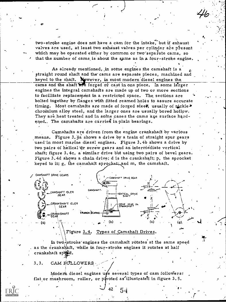
saw
=ro
two-stroke engine does not have a cam for the intake, but if exhaustvalves are used, at least two exhaust valves per cylinder aie pl.esentwhich may be operated either by common or twa'separate cams, sothat the number of cams_is about the s,p.me as in .a four-stroke engine.
As already mentioned, .in softie engines the camshaft is a 6straight round shaft and the cams are separate pieces, machined andkeyed to the shaft. wever, in most modern'diesel engines the,cams and the shaft forged ai cast in one piece. In some lergerengines the integral camshafts are made up of two or more sectionsto facilitate replacement in a restricted space. The sections are `bolted together by flanges with fitted reamed holes to assure accuratetiming. Most camshafts are made of forged sleet, usually of 4ckle-IPchroinium alloy steel, and the larger ones are usually bored hollow.They areheat treated and in soine cases the cams a.4e surface hard-ened... The camshafts are carried in plain bearings.
Camshafts are driven from the engine crankshaft by variousmeans. Figure 3.-5a shows a drive by a train of straight spui gear.sused'in most marine diesel.engines. Figure 3. 4b shows a drive bytwo pairs of helical-Or screw gears and an interthediate verticalshaft; figure 3.4c, a similar drive bcut using two pairs of bevel gears.Figure 3.4d shows a chain drive; d is the crankshaft; p, the sprocketkeyed to it; g, he camshaft spro and m, the camshaft.
CAMStiAFT DRIVE GEARS
"
9CAMSHAFT IDLER
7. -7) 4EAR
A
CO NKSHAFT IELERGEAR
CRA KSHAFTGEA
CAMSHAFT
TRUNION )EARAG
J.-CAMSHAFT DRIVE, GEAR
-E4
' ----VERTICAL DRIVESHAFT
c-CRIVE GEAR ON/ CRANKSHAFT
(b)
,
;.t.t..../.....
1
+,,, ,.......,.. __a,.., \-
m'
0 l\O A
e=1te, N
*( c )
: 1 . \ \H / 1411 \
.... 1 /(",4
Figkire 3.4. Types of camshaft Drives.
'*'. i(WI "AA
In tw stroke' engines the camshaft rotates' at the same speedas the Cranks ft, while in four-stroke engines it rotates at halfcrankshaft sp
..--3.3. CAM FlLLoWERa , .--
/ .Modern diesel engines u e several types of cam folloWers:
flat or mushroom, roller, or pfvoted as/illustrateli in figure 3.5.
42 5 4
0

-The combination of theconvex-flank cam with the flatmushroom follower causes aconsidierably faster vaLveopening and .closini and isused on smaller engines, run-ning at higher speeds. Thedisadvantage of s type offollower is a faster accelera-tion which results in higherinertia forces. On the other
(b) (c)
hand, this combination gives Figure. 3. 5. Cam Followers,a lower deceleration Of thevalve assembly as the latter approaches the top or nose of the cam,and consequently requires somewhat smaller spring forces to preventbouncing of the valve gear. Bouncing of the valve gear occurs afterit has reached the maximum acceleration point during the lifting ofthe valve, and from then on it must be decelerated as the followernears the top of the lift at the nose of the cam. The inertia of thevalve gear at this point tends to lift the valve faster than the camaction. If the valve spring does not have enough force to deceleratethe moving iparts of the valve gear at the same rate as the contour ofthe cam, the follower will leave the surface of the cam, if only foran instant. When it makes contact again, it does so with considerable,shock, causing pounding and excessive stresses and wear in variousparts of the valve gear. This is called bouncing and is undesirable.The sliding part, t, of a follower which moves up and down in a boredhole above the cam and takepotrenrde thrusts exerted by the cam iscalled a valve lifter or tappet.
The action of the pi-ftted follower resembles .t,he roller fol-,lower. Its main advantage is that the side thrust frOin the cam istaken by the pivot of the lever arm instead of by the sliding tappet aswith the other types. The rollers of the followers are made of steel,hardened and accurately ground to size and to a circle. It is im-giortant that the rollers havAittle or n6 play 4nd that they remainconcentric, meaning that the center of the outside circle and of thehole in one roller are at the same point.
3.4. ROCKER ARMS AND PLDSH RODS
'The rocker arm has one ena in contact with the top of thevalve stem, and the other end, by means of a hardened-steel roller,is in contact with the rotating cam profile as it rotates if the cam-shaft is near the cylin.dtr head; If the camshaft is located below theother end of the rocker arm,'-it is contact with the upper end of the
43

push rod; the lower end of the push rod is in contact with the rotat-ing cam through a cam follower. In Most designs, the rocker armis pivoted, not always at or near its middle, and the pivot pin,isheld in brackets secured7 the cylinder head.
.,.
When two or more valvesof a cylinder must be "opened andclosed at the same time, as in the case of the exhaust valves of someGeneral Motors Corporation two-stroke engines, one rocker armmay be used to Operate two valves by acting upon a "bridge" between,the valve stems. The bridge has special cams in contact with thevalve stems, and a lower extension acting as a guide. An auxiliaryspring is used under the bridge to offset its inertia and that of therocker arm, and to assist the valve sprtigs in maintaining the camfollower in contact with the c'am at all tinies.
3.5. l'ALVES
The intake and exhaust valves used in diesel engines are themushroom-shaped, poppet type as shown in figure '3.6. The valveassembly consists of a valve, valve spring, valve lock retainer,valve spring lock, valve stem cap, and lockring. The.purpose Ofthe valve spring is to hold the valve to the malchined valve seat toinsure a tight fit.
VALVE.SPRING LOCX
w
A
VALVE SPRING VALVE.LOCXRETAINER
Figure 3.6. Poppet Valve Assembly.
Poppet valves have heads with conically shaped or bevelediedges and bveled seats which give them self-centering action. The
bevel seatiOn poppet valves of most engines are ground to an angleof 45° to the flat side or plane of the valve head. On some they areground to an angle of 300 .
-;.,The material used to make an intake valve is usually carbon
or nickle steel. Although the intake valve is subjected to the heat ofcombustion, sufficient cool air flows over it when the valve is opento maintain a workable temperature. Exhaust valves present a dif-ferent problem from that of the intake valve. Instead of being cooled
44ki
-
gs/

by l w temperature air like the intake valve, the exhaust valve is be-ing Onstantly engulfed in hot exhaust gases and corrosive tempera-ture of these gases: Silicon-chromium steel (silichro-ne) is themat rial usually used for exhaust valves. Often a special materialsuc as stillite is welded to the seating surface of the valve head aswell as to the tip of the valve stem. ThisIncreases the hardness ofthe urfaces that are subjected to the constant pounding of openingand losing. To improve the wearing qualities of the valve stem,which usually operates in a valve guide of softer metal, the stems ofmanb exhaust valves are made of a steel different from that usedf. heads. The stems are welded to the heads to form built-upvalv
alve guides act as a bearing surface for the up-and-downmotio if the valve stems. These cylindrical sleeves are installedby dr' g them into place from the tops of the cylinder, using atool d igned for that specific engine. This tool serves as a stop forprope y positioning the guides in the head so that the lower end ofthe gu de is flush with the top of the specific valve. The guides areinstalled with the countersunk ends upward. After installation, theyare reamed to close tolerances with the valve stems to preclude anygas leakage passing down from the valve chambers. Additionally,this close valve stem guide clearance allows for the true seating.
All poppet valves formerly were seated directly on the sur-face of the cylinder head. This practice is still satisfactory for mostintake valves, but usually will not give good service for exhaustvalves of high temperature engines. Cast-iron seating surfaces tendto, soften and erode under the high temperature caused by the heattransfer from exhaust gases and contact with the hot exhaust valves.To increase the life of exhaust valves, most engines now have valveseat inserts installed. Valve seat inserts can be used with both in-take and exhaust valves, but are more frequently used with exhaustvalves onit These inserts are rings of a heat-resisting alloy whichfit into counterbored recespes in the valve port opening. They areheld in place by a shrink or press-fit of 0.0005 to 0.0025 inch. Thealloy used in inserts has approximately the same rate of heat expan-sion as the cylinder head; therefore, the insert is held firmly inplace at all operating temperatures.,
Valves for' large engines sometimes are assembled in cages,'which carry the valve, the seat insert, stem guide, and spring. The
cage is removable from the cylinder head as a unit and is usuallywater cooled. The cage is normally made of cast iron. A worn seat
AS insert can be, removed from the cage and replaqed.
45

3.6. VALVE SPRINGS
A valve spring closes the valve. Valve springs used ondiesel engines are made of round steel wire, woundiin a helical coil,as shown in figure 3. 6. Springs of this type have a force which isdirectly proportional to the amount they are compressed. Only asmall portion of the maximum valve spring force is necessary tokeep the valve tight on its seat. The principal duty of the valvespring, as mentioned before, is to provide sufficient force duringthe valve lifting process to overcome the inertia forces of the valvegear and keep it in contact with the cam 'without bouncing. This isobtained by putting the spring under compression when the valve isinstalled. When the valve is opened, this force is increased by addi-tional compression of the spring.
The space available for the valve spring is limited and there-fore it is not easy to design and construct a spring which will exertthe necessary force and still not break under the constantly repeatedchange of stresses. A spring made of wire with a small diameter issubjected to less, stress than one Made of wire with a larger diameter,but it also has a smaller force. In some engines two or more valvesprings with a small wire diameter are used to operate thr sralve gear.
Valve 'springs are mounted between supports located at theirends and known as spring seats. The lower spring seat may be sim-ply a recess in the top of the cylinder head or valve cage, or it maybea steel washer which rests on top of the cylinder head and is
/shaped to fit the bottom coil of the spring. The upper spring seat,called the spring or valve-lock retainer, is a steel washer shaped tofit the top of the spring and attached to the top of the valve stem by aremovable fastening.
The most widely used spring retainer has a conical recess inthe upper seat in which the valve stem is locked by a conical splitcollar, called a lock or keeper. This collar fits around the stem andinto one or more grooves turned in the valve stem, as shown infigure 3.7.
The pressure of theSPRING RETAINER KEEPER KEEPER spring on this retainer.tends
to hold the locks tightly inplace; yet they may be re-moved easily by depressingthe spring while holding tilevalve in its closed position.
Figure 3. 7. Valve -Spripg Retainers. There are two advantages to
465
so

7
this type of retainer and keeper: first, ;they do tiot loosen in service;and second, they givea strong fastening which does not result inweakening of the valve stem, which frequently occurs when other
*types of fastenings ari used. Some large diesel engines use valvespring retainers held in place by a lock nut which screws into threadso4 the upper end of the valve stem.
3, 7. VALVE LASH AND ADJUSTMENT
When the engine heats, the expansion of the valve stem and .
other parts of the valve gear 14ve a tendency to hold the valves offtheir seats. Some provision, therefore, must be made in the valvegear to take can'tlf this condition. The most common' method usedto permit this expansion is to provide a clearance or lash betweenthe top af the valve stem and the valve-lifting mechanism. Theproper lash is determined at the factory and is given,in the engine in-struction book. It is impOrtant that the valve lashspecified for thevalve be maintained. Too much lash causes noisy operation and ex-cessive wear. It also results in improper valve timing, since ,thevalve will open later and close sooner than it does with the properlash. Too little lash is even more serious since it may prevent thevalve from seating properly. This will result in valve leakage andburning of the valve-seating surfaces, and may even prevent combus-tion because of loss of compression.
All en'gines are provided with means for adjusting the lash orclearance in the valve gear somewhere betweenthe cam follower andthe valve stem. In most engines this adjustment consists of an ad-justable screw and lock nut located at one end of the valve rockerarm. The clearance is measured directly by inserting a feeler gaugebetween the tip of the valve stem and the rocker-arm roller. Thetypes of lash adjusters are explained in the following three subpara-graphs.
a. Automatic valve-lash adjusters are Used to avoid thenecessity of a clearance between the cam and the follower regardlessof whether the engine is cold or wa;m and, by insuring a constant con-tact between the cam and the follower, to eliminate'the shock action,at the beginning of the valve opening. They also eliminate the needfor manual adjustment to take care of the wear at various points of
the valve gear.
b. A mechanical valve-lash adjuster is incorparated in thevalve,bridge. A spiral spring has a tendency to turn the cam, asshown by the arrow in figure 3.8, when the cylindrical spring pushesthe bridge'to its highest position. The spring takes up any clearance
47
^
6'7

/I
Figure 3.8. Cam ofa Mechani-cal LashAd'uster.
betWeen the various parts of the valve-actuatingear, and the turning of the cams takes up
clearance between the ends of the bridge andthe upper spring seats solidly connected to thevalve stem.
s. Hydraulic lash adjusters may be builtinto the valve tappets, but with valve-in-headengines they are generally built into the end ofthe rocker arms or the valve bridges whichoperate directly on the ends of the valve stems.Figure 3.9 illuktrates su"ch an adjuster. Itconsists essentially of a small cylinder, re-ferred to as the liTter cylinder, containing apiston or plunger, a spring, and a ball check
valve. It is positioned between the push rod and the rocker arm end.In operation, oil under pressure from the lubricating oil systementers the lifter cylinder pastthe ball check valve and istrapped under the plunger.Any force exerted against theouter end of the plunger istransmitted to the cylinder,mounted in the valve gear, bytfie entrapped oil. The valveis thus actuated just as if thelash were taken Alp mechani- OIL
cally. Since the spring insideof the cylinder acts to forcethe plunger outward, anyclearance between the valveand its lifter is taken up, andthe oil pressure immediatelyfills up the lifter cylinderthrough the check valve. If the valve stem expands, there is suffi-cient leakage of oil past the Ourrger to permit it tp move in slowly.so there is.no danger of holding the valve,open.
ADJUSTING SCREW
HYDRAULICPLUNGER
LIFTERCYLINDER
LOCK NUT
POCKER ARM
PLUNGERSP ING
SSURE
SNAP RING
END OFPUSH ROD
BALLCHECK VALVE
Figure 3. 9. Hydraulic LashAd'ustei.
3. 8. SUMMARY
The operation of the valves in a diesel engine is started bythdcams fixed to the rotating camshaft. The movement is trans-ferred to the valve by the valve gear. The first piece of the valvegear is the cam follower which makes contact with the cam. Thecam follower can be one of three types: flat or mushroom, roller,or pivoted. The next piece of gear is the push rod which transmits
48
6u
c? ,/

the motion from the cam follower to the rocker arm. The rockerarm is pivoted in its middle and is pushed by the push rod on onearm and operates the valve with the other.
The valve and its mechanism consist of the valve, valvespring, valve-lock retainer, vallie-spring lock, an'd lockring. Thevalve can be adjusted for lash or plty by three methods: mechanicaladjuster, hydraulic adjUster, or automatic adjuster.
The mechanical valve-lash adjuster i's incorporated in thevalve bridge. A sprilag takes up any clearance betWeen the variouspoints of the valve-actuating gea'r. The hydraulic ldsh adjuster maybe built into the valve tappets, but with valve-in-head engines theyare generally built into, the end of the rocker arms or the valvebridges which operate directly on the ends of the valve stems. Auto-matic valve-lash adjusters are used to avoid the necessity of a clear-ance between the cam and the follower regardless of whether theengine is cold or warm and, by insuring a constant contact betweenthe cam and the follower, to eliminate the shock action at the begin-ning of the valve opening.

(
Ghapter 4
FUtI... INJECTION SYSTEMS
4.1. INTRODUCTION
The fuel injection system is the most intricate of all systemsaffecting the operation of a diesel engine. Originally there were twomethods of fuel injection: air injectibn and mechanical or solid injec-tion. Air injection is now obs-olete. Mechanical injection may bedivided into three distinct system'scommon-rail, individual-pump,and distributor. Because this is a basic course, the study of fuel in-jection systems covers only fundamental principles. A more detailedstudy is found in Reference Text 447.
4.2. REQUIREMENTS OF FUL INJECTION SYSTEMS
Efficient operation of a diesel engine requires that the fuel in-jection system perform the functions outlined in subparagraphs athrough e. The means of performing these functions vary accordingto the system used.
a. Metering 'or measuring of the. fuel mein's t171, for anygiven throttle setting, the same amount of fuel delivered for eachcycle must be in accordance with the engine requirement, and exactlythe same amount of fuel must be delivered'to each cylinder for each
power stroke. Only in this manner will the engine operate at uni-form speed with a uniform power output.
b. Timing means accomplishing fuel injection at the correctpoint and time in the cycle at all engine speeds and loads. This isessential to obtain maximum power from the fuel and insure cleanburning. When the fuel is injected too early in the cycle, ignitionmay be delayed' because the temperature at this point is not high
enough. An excessive delay<causes rough and noisy operation of theengine and p1erthits fuel to be lost through wetting of the cylinderwalls and sto14 head. Unburned fuel may accumulate, producingexcessiv prelsure and .resulting.in noisy operation and poor fueleconom . When fuel is injected top late in the cycle, all the fuel isnot burned until he piston is well into the power stroke. When this
N. 50
6\ z

happens, the engine does not develop its maximum power, the ex-haust is hotter than normal, and the fuel consumption is high.
:4
c. Rate of injection is the amount of fuel that is injected intothe combustion chamber in a particular time or degree of crankshaftrotation. When the rate of injection is too high, a metered-amount offuel is injected in too short a period, or during an insufficient num-ber of degrees of crankshaft rotation. When it is desired to decreasethe injection rate, a nozile tip with smaller holes is used to increasethe duration of fuel injection. The,effective rate of injection uponengine operation is similar to that of timing. When the rate is toohigh, the results are similar to an early injection. ,.When the rate istoo low, the results are similar to excessively late injection.
d
,d. Atomi:zation is the breaking up of the fuel stream into afine, mistlike spray. Some combustion chambers require` a veryfine atomization, ,while others operate with a coarser atomization.Proper atomization facilitates the starting of the burning process andinsures that each minute particle of fuel is surrounded by oxygen forefficient burning.
e. Distribution of the fuel must be such that the fuel willpenetrate throughout the combustion chamber where oxygen is avail-able for combustion. If the fuel is not properly distributed, some ofthe oxygen will not be used and the power output of the engine will below.
4. 3. COMMON-RAIL INJECTION SYSTEMS-
The basic common-rail system consists of a high pressurepump which discharges fuel into a common rail or hfader to whicheach fuel injector is connected by tubing. A spring-\oaded bypassvalve on the header maintains a constant pressure in the system,returning all exceSS fuel to the fuel supply tank. The fuel injectorsare operated rnechaiically, and the amount of diesel fuel oil injectedintd the cylinder during each power stroke ie controlled by the lift ofthe needle valve in the injector. The principal partb of a basicc.common-rail, system,are shown in figure.4. 1.
The pressure regulator, which functions as a relief valve, isgenerally built integral with the high pressure pump. When the en-gine load drops off, the fuel consumption decreases and the valve by-passes the excess diesel fuel oil delivered by the pump. When, a loadis added resulting in increased fuel consumption, the amount of by-passed oil is reduced.
51

t:urN tO 1411.sk,Pet
1
M.KNON ANOOtSCHAeGI ALt
CAGE
6u1IPRESSult
ithAitAtOlt011.Nf VAI
4
1$01A1rNoVAlvt
^411..
It `ri.tt,fOr
COMM.N
,IN,f0,01440::tt
r1.64 1100
fult DUll10 'War,
ACCUMULAfOk
C
PIMPING IUNNAlhOtt
/AMMO CINNIHNmoscie Gulon
Figure 4.1. Basic Common-Rail System (Cooper-Bessemer).
The spray or injection nozzle extends from the top of the cyl-inder head down into the combustion area, It conlists essentially ofa multiple=spray tip, a valve seat, and a needle valve extending thefull length of the nozzle and held to its seat by a apririg. The highpressure is conducted from the fuel,header to the spray tip, immedi-ately above the valve seat. When the needle valve is lifted verticallyfrom its seat, fuel is sPrayed into the Combustion chamber.
The duration of the injection periods depends upon the lengthof time the valve .is off its seat. The quantity of fuel injected dependsupon the period of injection-, the size and number of hales in the tip,and the operating pressure. The needle valve is lifted mechanicallyby a system of push rods and cross rods, actuated by a timed cam-shaft. The duration period of the 'needle valve opening depends uRonthe clearance between the cam and push rod znechanism. A minimumclearance promotes a greater needle valve lift; a maximum clearancecarried to the extreme will not transmit the cam lift to the needlevalve, as is the case when the throttle is in the OFF position. Awedge mechanism, located between the cam and push rod mechanism
c9 6 q

controls the amount of clearance and affects carn lift. Figure 4.2sb:ows a fuel contrell mechanism.
1On some engines, the
wedge is located between thecross rod and the injectionneedle valve. Whenthewedgesare pushed in all the way, aminimum clearance exists.The inclined plane of the camcontacts. the needle openingpush rod sooner and raisesthe nozzle needle earlier.Since the Contour of the clos-,ingnside of the cam is usuallythe same as that of the open-ing side, the needle returnsto its seat an equal number ofcrankshaft degrees late as itwas degrees early in opening.
The wedges are at-tached to a single shaft whichis coupled to the governor orengine throttle, depending onthe service of the engine.Consequently, they are movedin or withdrawn as the engineload changes to increase ordecrease cam to push rodclearance and vary the dura-tion of injection, as needed,to meet the demands of the engine.
WEDGE if INWARilPOSITION
MINIMUM CLEARANCEMAXIMUM FUEL
.4-- PUSH ROD
PUSH RODGUIDE
_ .
II
WEDGE
UFTER-?
I GU/DE_
i WEDGE AT OUTWARD ;POSITION
MAXIMUM CLEARANCEMINIMUM FUEL
Figure 4.
GUIDEHOUSING
-FUEL CAM
CAMSHAF f
Fuel ControlMechanism.
Engine performance is affected by the duration of the injectionperiod. A shorter period is advantageous in sta'rting the engine orwhen running at light loads. A longer period is necessary at greaterloads.
An isolating valve is located in the line from the commonheader to each nozzle. Having individual cylinder isolating valvespermits shutting off any one of the nozzles. The fuel injection sys-tem has an accumulation bottle on the pressure side of the pump toincrease the volume of fuel lathe system. A large volume of oil
dampens the pumping pulsations 'andorhaintains a constant supply onthe header.
53
6 6
/
4.4

OA,
The common-rail system is not suitable for high-speed, smallsmall bore engines because it is difficult to accurately control thesmall quantities of fuel injected into^ each cylinder at each powerstroke.
4.4. INDIVIDUAL-PUMP INJECTOR SYSTEM
Individual-pump systems are designed to meet the demandsof modern, high-speed engines. This system, also known as thejerk-pump system, has two essential parts to each cylinder, the in-'
,jection pump and the spray nozzle. The injection pump raises thepressure, meters the charge, and times the injection. An individualpump serves each cylinder on large engines. The pump or pump cyl-inder is connected to a spray nozzle containing a spring-loaded checkvalve.
-In most jerk pumps, the total plunger stroke is constant andthe metering is controlled by varying the length of the effective partof the plunger stroke, by one of the following methods:
a. The fuel is admitted into the pump barrel through portsin the barrel controlled by a spiral groove or scroll, also called thehelix on the plunger. The plunger can be turned in the barrel whilemoving back and forth. This changes the portion of the plungerstroke during which the ports are covered and the fuel is deliveredto the nozzle.
b. The fuel is admitted into the pump barrel through portsin the barrel controlled by a, separate valve.
4 The principle of the plunger-controlled pump can be bet-ter understood by referring tofigure 4.3. At the bottom ofthe stroke, the suction' and
_pressure release ports areboth 'in communication withthe inner pump spk6e: Whenthe plunger has moved a cer-tain distance and covered bothports, fuel delivery begins
(CO (b)with a jerk and lasts until the BOTTOM END OFOF STROKE DELIVERYlower edge of the spiral begins(MAXIMUM DELIVERY)
to uncover the release port.At that point, the pressure Figure 4.3. Barrel With Vari-drops and fuel delivery stops. ous Plunger Posi-The plunger continues to teavel tions.
(e) (d) (e), BOTTOM END OF BOTTOM
OF STROKE DELIVERY OF STROKE(NORMAL DELIVERY) (ZERO DELIVERY)
54
6b

. tc;Cf' a sho-it distance to the top of its stroke and tlien begins to move dor-
ward. If the plunger is turned about 600, the distance between the-top edge of the plunger and the edgy of the spiral sliding over the re-lease port is shorter, and the fuel delivery stops earlier. Finally,if the plunger is turned 900 more, the release port stays uncoveiedand no fuel is delivered.
In the operation as shown in,figure 4.3, the beginning of theeffective stroke always occurs at the same moment, but thei end ofthe.injection changes with the engine load. It is later with a higherload, greater fuel delivery, and earlier with a lower load, smallerfuel delivery; The middle of the injection stroke is advanced v.)ith a
_load increase.
This condition can be reversed by making a spiral edge at thetop of the plunger and a square groove at its bottom. In this case thebeginning of .the injection will be earlier with an increase in the loadand later with a decrease in it, while the end will be always constant.The middle of the injection is retarded with an increase of the load,a condition, which however, is not desirable. By making both edgesspiral, inclined in opposite directions, the middle of the injectionstroke can be kept constant for all,loads.
Naturally, the compressibility of the fuel and the mechanicalflexibility in the pump mechanism retards the actual start of injec-tion into the cylinder, producing an injection lag.
4.5. FUZI., NOZZLES
e nozzles are either the open or the closed type. Tile opentype usally is a simple spray nozzle with a check valve which pre-vents the high-pressure gases in the engine cylinder from passingto the pump. Although the open nozzle is simple in construction andoperation, it is not generally used because it does not fully atomizefuel. The closed nozzle is used more commonly. Basically, it is ahydraulically operated, spring-loaded needle valve. Most closednozzles open inward under the pressure acting on the differentialarea of the needle valve. They are seated'by a spring when thepressure is cut off, as shown in figure 4.4. The larger cylindricalpart of the valve has a lapped fit with the nozzlembody. The two maintypes of such nozzles are the pintle and the hole. The valve f the
-
.001°4 pintle nozzle, as illustrated in figure 4.5a and .13, has a pin or pintleprotruding from the hole in the bottom,-ref4he nozzle, causing a closefit. The fuel delivered by such a nozzle must pass through anannular or ring-shaped orifice. The spray is in the form of a hollowcone, whose outside angle, which may be any angle up to 600, is
55

ADJUSTINGS9REW
SkING
HOLDERBODY
SPINDLE4
CAP NUT
N-..,
NOZZLEBODY
LEAK-OFFCONNECTION
FUELINLET
FUEL DUCT
STEM
VALVE
Figure 4.4. Bosch Fuel-InjectionNozzle.
(c)
SINGLE NOLE MULTI-MOLENOZZLE GLOM* NOZZLE-OPEN
figure 4.5. Types of ClosedNozzles.
Multi-hole nozzles are used generallyCombustion chamber.
/
il.
,determined by selecting cer-tain dimensions. A valuablefeature of the pintle nozzle isits self-cleaning property,which prevents carbon de-posits from building up inand around the orifice. .
As shown in figure 4.5c eand d; the hole-type nozzlemay have one spray orificeor it may have several. Theone with several orifices,called a inulti-hole nozzle,has round holes drilled'through the tip of the nozzlebody below the valve seat.The spray from the single-hole nozzle is relativelydense and has a greatet pen-etration. The general spraypattern of a multi-hole noz-zle, which may or may notbe symmetrical, is deter-mined by the numbe r, siz e,and arrangement of the holes.Orifices used are from 0.006inch up' to 0.0225 inch indiameter, and their numbermay vary from three up toas many as 18 holes per noz-zle for large-bore engines.
in engine's with an individual
Figure 4.4 shows a pintle nozzle assembled in a nozzle holderwith the spring and connections for the fuel-pressure line and leakagedrain. The pressure necessary to open the needle valve may varyfrom 1,500 psi to about 3,000 psi.
4.6. UNIT INJECTOR
The unit injector combines a pump and a fuel-spray nozzle inone unit, as shown In figure 4.6. It is a jerk pump with ports con-trolled hi helical-grooved edges ..in the plunger. The amount of fuelis controlled by turning the plUnger. Figure 4.6 shows an open
, 56 60
/
..
i

nozzle with a sphericalcheck valve. -The spray tiphas:several small orifices.However, unit injectors arealso ha exiseence which haveclosed nozzles with hydrau-liCally- operated differentialneedle valves and multi-holelnozzle tips.
The pump plungerreceives its downward mo-tion--the delivery stroke--from a fuel cam through a.rocker arm which acts on,the piunger follower. Theplunger is returned by theplunger spring. The fuel,under a pressure of about35 psi, is admitted througha small filter and fills theannular supply chamberaround the pump plungerbarrel, ,.called a bushing.As the plunger moves down-ward, fuel. is displaced intOthe supply chamber, at firstthrough the lower port, and later when the lower kedge oftthetp,lunger_ Acloses this port, through a central and a transverie port or czoss-. _wise drilled holes in the plunger and the upper port. When the upperhelical edge has "coVered the upper port, the fuel from the pumpplunger barrel is forced down into the nozzle body, opening thespherical check valve, past the flat check valve, and into the spraytip. .From,there it is forced through the orifices into the cylinder.The fuel-injection pressure is raised to approximately 20,000 psi asthe fuel passes through the nozzle. Injection continues until thelower helix on.the plunger uncovers the low.er Port in the plungerbarrel. The fuel then begins to bypass through the holes in theplunger and through the lower poreinto the supply chamber. Thisreleases the pressure on the fuel in the plunger barrel, and the checkvalve ipring causes the spherical check valve to seat. On the returnstroke, the upward movement of the plunger fills the plunger barrelwith fuel oil.which flows from the supply chamber through the lowerport. The function of the flat check valve is only to close the insideof thernozzle to keep combustion gases 4zorn entering the injector.
124
FOLLOWER
ASKET
KIECTO1BOOT
FIVER
Dowa
CONI101.RACK
WPM PORT
CHECK VALVECAGE
SPRING CAGE
SPRING SEAT
Figure 14.6. unit InjectionAssembly.
.
57
6 d

Turning of the pluziger to change the effective length of thestroke is accomplished by a gear and rack connected to the governoror hand throttle. The middle part of the plunger has a heXagonalcross section which slides through a corresponding hole in the gear,thus forcing the plunger to turn with the gear. The effective strokeis determined by the relative positions of the helices and the upperand lower ports.
The advantage of the unit-injector construction is in theabsence of long fuel lines which cause pressure waves and sometimesmechanical troubles. However, one 4sadvantage lies in the'highpressures created. Such pressures (esult in faster wear of the sprayorifices and necessitates dismantling a considerable part of the valvegear to take out one unit injector. Another disadvantage is the greaterchance of fuel leaks into the engine sump and dilution of the lubricat-ing oil.
4.7. DISTRIBUTOR SYSTEM
Of the several distributor systems used in different makes ofengines, the only one in use at present in Army vessels .is theCutmins system. Although essentially a distributor system, it has
'-`4-1141'''retiteciaLazatcteristic features of a unit injector and is sometimes clas-sified as such.' ii:rthis syktem,Juel under pressure ranging from130 Psi to 150 psi is 'supplied by a gear 'ffansfer _pump, as ishown infigure 4.7, through an indexed rotating distributor, to' a metirizig':plunger during its downward stroke. This plunger has a variable ;-stroke, controlled by the governor, and receives its upward motionfrom a multi-lobe cam and the downwardrnotion by a spring. During theupward stroke, this plunger sends the fuelthrough other passages inthe same distributor to the individual injectors on each engineder. The fuel enters at the top of the injector, as illustrated infigure 4.7, flows through an inlet passage past a spring-loaded checkvalve, and fills the chamber under the injector plunger which, exceptat the end of injection, is off its seat. The injector plunger isoperated by a cam through a rocker lever and link. As the fuel isdelivered from the distributor to the injector 4uhring the sudtionstroke of the engine, the injector plunger is "gradually lifted and thefuel fills the space in the cup under the plunger. At the tiThe of in-jection, the plunger is pushed downwardand the fuel prevented by thecheck valve from returning to the distributorkis injected into the com-bustion space. It is,finely atomized by being forced under a relativelyhigh pressure through six small holes, '0. 006,inch to Y. 008 inch indiameter, depending upon the size of the engine.
58

2*ROCKER LEVER
PLUNGER LSO
INLJECTCR PLUNGER SPRINGDISTRIBUTOR DtSK HOUSING COVER
DEXED FOR DISCHARGEISTRIBUTOR SHAFT
PRESSURE REGVALVE
NJECTOR BOWCOPPER INSERT
WATER JACKETCHECK VALVE
CYLINDER HEADhJECTOR PLUNGEROUTSIDE FUEL CUP
,..-GEAR PRESSUREPUMP
CONTROL LINKI CAM ROCKER LEVER
FUEL, PUMP CAMSHAFTTURNING CRANKSHAFT SPEED ,-
riNDEXED FOR ADMISSION
INSIDE ADAPTER
\-DISTRIBU 01$e
Figure 4.7. Schematic of Cummins Distributor System.
The advantage of this sYstem is the absence of high.pressurelines and pressure waves. Its disadvantage is the relatively largeinertia of moving parts, making it not suitable for very high speeds.Another disadvantage, more or less eliminated in the new type injec-tor, is dilution of the lubricating oil in the engine crankcase becauseof leaking of fuel oil past and up the injector plunger.
4. 9. SUMMARY
The diesel engine must have its fuel injected into its cylinder.The fuel injector has to fulfill the following requirements: metering,timing, rate of injection, atomization, and distribution. Fuel can beinjected into the cylinder by three different systems, depending uponthe type of engine--common-rail, .individual-pump, or distributorsystern.
The basic common-rail system Consists of a high pressureum p which discharges fuel into a common rail to which each fuel in-
jector is connected by tubing. A spring-loaded bypass valve on theheader maintains a constant pressure in the system, returning allexcess fuel to the fuel supply tank. The individual pump system isdesigned to meet the demands of modern, high-speed engines. Thissystem has two essential parts to each cylinder: the injection pumpand the spray nozzle. The nozzles are either of the open or closed
-type: -The open type usually is a simple spray nozzle with a checkvalve which prevents the high-pressure gases in the engine frompassing to the pump. The closed type, the most commonly used, isbasically a hydraulically operated, spring-loaded needle valve. Theunit'iiijeCtor combines a fuel pump and spray nozzle in one unit orbody. The distributor system is essentially the same as a unitinjector.
59-

Chapter 5
GOVERNORS
5. 1. INTRODUCTION
To control an engine means to keep it running at a desiredspeed, either in accordance with or regardless of the changes in theload carried by the engine. The degree of control required dependsupon the engine's performance characteristics and the type of loadwhich it drives.
In diesel engines, a varying amount of fuel is mixed with aconstant amount of compressed air inside the cylinder. A full chargeof air enters the cylinder during each intake event. The amount offuel injected into the cylind,rs controls combustion and thus deter-mines speed and power output of a diesel engine. A governor regu-lates the flow of fuel.
5,2, TYPES Ofr GOVERNORS
Essentially a speed sensitive device, governors are designedto maintain a reasonably constant engine speed regardless of loadvariations. Since all governors used on diesel engines control enginespeed by regulating the quan,tity-of fuel delivered to the cylinders,they may be classified as speed regulating governors. They mayalso be classified according to the function or functions performed,the forces used irloperation,, tind the means by which they adjust ormove the fuel control mechanism.
The function a governor must perform on a given engine isdetermined byfthe load on the engine and the degree of control re-quired. .Subparagraphs a through d classify governors according totheir use.
a. Constant speed governors Maintain a constant enginespeed 'regardless of load.
4\
b. Variable speed governors maintain any desired enginespeed between idle and maximum.
60 7

,i
i
c. Speed limiting governors keep an engine from exceedinga specified maximum speed and from dropping below a specifiedminimum.
d. Load lizniting governors limit the loaethe engine willhandle at various speeds.
t5.3. TERMS AND DEFINITIONS OF GOVERNORS
Before going into the operation of governors, study the follow-ing terms and their definitions so that you can better understand ma-terial this chapter discusses.
Hunting--continuous fluctuation of the engine speed (slowingdown and speeding up) from the desired speed. Hunting is caused byovercontrol by the governor.
Isochronous governingmaintaining the speed of the enginetruly constant, regardless of the load. This means governing withperfect speed regulation or zero_speed drop.
sPromptness--speed 6f action of the governor. It identifies
the time interval required for the governor to move theY fuel controlmechanism from a no-load position to a full-load pos'ition. Prompt-ness depends upon the power of the governor; the greater the power,the shorter the time required to overcome the resistance.
Sensitivitychange in speed required before the governorwill make a corrrective movement of the fuel control mechanism andis generally expressed as a percent 6f the normal or average speed.
I
Speed drop--decrease in speed of the engine from a no-loadcondition to a full-load condition. Speed drop is expressed in rpm,or more commonly as a percent of normal or average speed.
Stability--ability of the governor to maintain the desiredengine speed without fluctuations or hunting.
5. 4. OPERATING PRINCIPLES
..
In most of the governors installed on diesel engines used bythe Army, the centrifugal force of rotating weights (flyballs),and thetension of a helical coil spring (or springs.) are used in governoroperation. On this basis, these governors are generally referred toas spring-loaded centrifugaloivernors.
61
4
I
,

In spring-loaded centrifugal governors, two forces opposeeach other. One 41f/these forces is the pressure of a spring (or IC
springs) which may be varied either by an adjusting device or bymoving the manual throttle. The' other force is produced by the en-gine. Weights attached to the governor drive shaft are rotated and acentrifugal force is created when the shaft is driven by the engine.The rriagnitude of the centrifugal force varies directly with the speedof the engine.
Transmitted to the injectors through a cOn,necting linkage,the pressure of the spring tends to increase the amount of fuel de-livered to the Cylinders. On the other hand, the centrifugal force ofthe rotating weights, through connecting linkage, tends to reduce thequeitity of fuel injected. When the two opposing forces are equal orbalanced, the speed of the engine remains constant.
To illustrate how the centrifugal governor works, assume thatan engine is operating under load and that the opposing forces in thegovernor are balanced so that the engine speed is constant. If theload is increased, the engine speed decreases and a resultant reduc-tion i±i the centrifugal force of the flyballs will take place. The, ,spring pressure then becomes the greater force and it acts on thefuel control mechanism to increase the quantity of fuel .aelivered tothe engine. The increase in fuel results in an increase in enginespeed until balance of the forces is-again-reatlited.
When the load on an engine is reduced or removed, the enginespe.d increases and the centrifugal force within the governor in-creases. The centrifugal force then becomes greater than the springpressure and acts on the fuel control linkage to reduce the amount offuel delivered to the cylinders. This'causes the engine speed to de,-crease until a balance between the opposing forces is again reachedawl engine speed becomes constant.
5.5. REGULATION OF FUEL CONTROL MECHANISMS
Governors may be classified according to the method by whichthe fuel control mechanisms are regulated. In some governors, thecentrifugal force of the rotating weights regulates the fuel supplydirectly through a mechanical linkage which operates the fuel controlmechanism. Other gOVernors are designed so that the centrifugalforce of the rotating weights regulates the fuel supply indirectly by
,moving a hydraulic pilot valve which controls oil pressure. Oilpressure is then exerted on eiiher side of a pOwer piston whichoperates the fuel control mechanism.
62 7

4 b7Governors which regulate the fuel,supply directly (through
mechanical linkage) are called mechanical governors; those whichcontrol the fuel supplY indirectly (though oil pressure), hydraulicgovernors. Simple mechanical and hydraulic governors are shownin figures 5. 1 and 5.2.
SPRING
PLYSALL
FULCRUM
7
4.FULCRUM
PUEI. PIPE
FUEL Or
FUEL OFF
POWERPISTON
4
61115inil
1PILOT VALVE
1111
PASSAGE S
FROI4 PUMP
FUEL PIPE
Figure 5.1. Simple Mechanical Figure 5.2. Simple HydraulicGovernor. Governor.
Note that in the illustration of the mechanical governor, theweights (flyballs) are in an upright position. This indicates that thecentrifugal force of the weights and the pressure of the spring arebalanced; in other words, the engine is operating at constant load andspeed.
In the illustration of the hydraulic governor, the positions ofthe parts indicate that the engfge is responding to an increase in loadwith a resultant decrease in engine gpeed. Note that the weights tiltinward at the rtop. As engine speed decreases, the spring pressureovercomes the centrifugal force of these rotating weights. When thespring pressure is greater than the centrifugal force of the flyballs,the governor mechanism permits oil under pressure to force the pis-tdn te increase the fuel valve opening. The increased fuel supplycauses an increase in engine power output and speed. the governorregulates the fuel supply so that sufficient power is developed tohandle the in rease in load.
Thrre is alwayg a lag between the moment that a change infuel settiyig is made and the time the engine reaches the new desiredspeed. Even though the fuel controls are 'set as required during a
63

speed change, hunting atited by overshooting will occur. As long asengine speed is above r below the desired speed, the simple hydrau-
.
lic governor will conti4. to adjust (overcorrect). the fuel setting tovdecrease or increase t1 delivery of fuel. For this reason, a hydrau-
lic governor must inclucM a mechanism which will discontinue chang-ing the fuel control setting slightly before the new setting requiredfor sustaining the desirea speed has actually been reached. Themechanism which accomplishes this process in all modern hydraulicgovernors is called a compensating device.
One type of compensating device is illustrated in figure 5.3.In the one illustrated, the pilot valve plunger operates in a movablepilot valve bushing in which are located the ports controlling the oilflow. The movement of the valve bushing during a speed change iscontrolled by the receiving compensating plunger. The compensatingaction of the valve bushing is controlled hydraulically by transfer andby leakage of oil between the compensating receiving plunger and the
IllziSPEED ADJUSTMENT
Tfr
POWER SPRING
POWER PISTCN
ACTUATINGCO"PENSAT ING
PLUNGER
rFuE,cc; It
;.;tAGE
PILOT VALVE'0ER
SPEED AO.UST'NG SP R
461j
CEVNG COmPENSATING PLUNGED
COMPENSATINGSPR NG
PILOT VALVEBUSHING
R 4,4 G LUAU 0. ACCUMULATORS \
/OIL srPASS TCMAINTAIN cONSTANPREESuRE
COmikNSATION ;
NEEDLE t,VALVES !:
GEAR PUMP
I)
DRIVE' 1
SNAF 1__.1
!r 1
I ,
SPRING
GOUPL'NO
OIL SUM
Figure 5.3. Hydraulic Governor with Compensating Device.
64 76

4
compensating actuating piston. The rate of compensation is adjustedto fit the engine characteristics by regulating the oil leakage throughthe compensating needle valve. If the compensating needle valvesare adjusted correctly, only a slight amount of hunting will occurfollowing a load change. This hunting will quickly be dampened out,resulting in stable operation through the operating range of thegovernor.
Hydraulic governors are more sensitive than the mechanical,ones. The design of a hydraulic governor enables a comparativelysmall governing unit to cOntrol the fuel mechanism of a large-engine.The mechanical governor is more commonly found on small engineswhich do not require extremely close regulation of the fuel. Hydrau-lic governors are more suitable for larger engines in which moreaccurate regulation of fuel is necessary.
5.6. OVERSPEED SAFETY DEVfCES
A Engines maintained in proper operating condition seldomreach speeds above those for which they are designed. However,there may be times when conditions occur which may result in speedsbecoming excessively high. The operation of a diesel engine at ex-cessive speeds is extremely dangerous because of the relativelyheavy construction of the engine's rotating parts. If the engine speedis sufficiently high, thOnertia and centrifuga). force developed maycause parts to bedOme Seriously 'damaged or swen to fly. apart. ---
,-*--.11)-e-rglare-.--#-x..1-els..sentia.L.t.11,11..yo.u...know....why_ax. engine may reach adangerously high speed, and how an engine may be brought undercontrol when excessive speed occurs.
In .some two-stroke-cycle engines, lubricating oil may leakinto the cylinders as a result of leaky blower seals or broken piping.Even though the fuel is shut off., the engine may continue to operate,or even "run away, " as a result of the combustible material comingfrom the, uncontrolled source. Engines in which lubricating oil mayaccumulate in the cylinders are generally equipped with an auto-*,matically operated mechanism which suts off the intake air at theixilet passage to the blower. If an air shutoff mechanism is not pro-vided and shutting off the fuel will not stop an engine which is over-speeding, anything which can be placed over the engine's intake tostop airflow will stop the engine. WARNING the component placedover the air intalse must be large enough to overlap"the air intake soit will not be drawn into the engine.
Excessive engine speeds Are more commonly associated withan improperly functioning regulating governor rather than with
65
..0114. "Iv -_

4
/
7
lubricating oil a,bcurnulations in the cylinders. Whereas stopping theflow of intake agr is used as a means of stopping an engine which iso'verspeeding be,bause of lubricating oil in the cylinders, a means of
shutting off or decreasing-the fuel-supply to the cylinders is morecommonly used to accomplish an emergency shutdown or reduction of
engine speed when the regulating governor fails to function properly.
Shutting off the fuel supply to the cylinders of an engine may
be accomplished in various ways. The fuel control mechanism may
be forced to the "no fuel" position; the fuel line may be blocked by
closing a valve; the pres-sure in the fuel injection line may be relievedby opening a valve; or the mechanical movement of the injection pump
may be prevented. These methods of sh'utting off fuel supply may beaccomplished by either manual ci,r automatic means.
Automatic operation of fuel and air control mechanisms isaccomplished by overspeed safety devices. As emergency controls,these safety devices operate only in the event that the regular speed
governor fails to maintain engine speed within the maximum design
limit. Devices which function to bring an overspeeding engine to a
full stop"b-k compretely shutting off the fuel or air supply are generallycalled overspeed trips. Devices which function to reduce the exces-sive speed of an engine, but allow the engine to operate at safespeeds, are more commonly called overspeed governors.
All overspeed governors and trips depend upon a spring-loaded
centrifugal governor element for their operation. In overspeed de-vices, the spring tension is sufficiently great to overbalance thecentrifugal force of the weights until the engine speed rises above thedes-ired Maximum: When an excessive speed is reached, the centri-fugal force overcomes the spring tension and operates the mechanismwhich stops or limits the fuel or air supply.
When a overnor serves as the safety device, the actual opera-tion of the f or air control mechanism by the centrifugal force 7
may be'acc mplvhed directly, as Ina mechanical governor, or in-directly, as in a hydraulic governor. In an overspeed trip, the thut-
off control is operated by a power spring. The spring is placed under
tension when the trip is manually set and held in place by a latch.
If the maximum speed limit is exceeded, a. spring loaded centrifugalweight moves out and trips the latch, allowing ill-L.-power spring to
operate the shutoff mechanism. Overspeed safety devirs mustalways be operative and must -never be disconnected for any rea,00n
while tile engine is operating.,
66
)?

5. 7. SUMMARY
To maintain a regulated speed in a diesel engine, regardlessof load, a governor must be installed. To maintain a constant speedunder any load, a constant speed governor is used. To maintain anyspeed between idle and maximum speed, a variable governor is used.A speed limiting governor, is used to keep an engine from exceedinga set maximum speed. A load limiting governor limits the loadwhich an engine will handle at various speeds.
A governor may be classified according to the method bywhich the fuel control mechanisms are regulated. The governor thatcontrols thè fuel by the _centrifugal force of rotating weights througha mechanical linkage is a mechanical governor. The hydraulicgovernor is designed so that the centrifugal force of the rotatingweights regulates the fuel supply indirectly by moving a hydraulicpilot valve.
6 7
7/

AR 310-25
AR 310-50
Apperidiza
REFERENCES
Army Regulations
Dictionary of United States Army Terms
Authorized Abbreviations and Brevity Codes
Technical Manuals
TM 55-503 Marine Salvage and Hull Repair
TM 55-509 Marine Engineman's Handbook
l(Tavy. Publications,
NAVPERS I6178-A FundamentaIs of Die sel Engines -U. S. N'avy
NAVPERS 10541-A -Enginernan 3 & 2
68
by .

Appendix II
GLOSSARY
Accelerateto increase the speed of movement, such as increasingthe speed of a piston or flywheel.
Air inlectionsystem of injecting fuel into the combustion chamberof a diesel engine by means of a blast of highly compressed air.
Alloycombination of two or more metals mixable with each otherwhen molten.
Annularhaving a ring form.
Babbitsoft.alloy of tin, copper, and antimony used to line bearingshells.
Bearing--support for a revolving shaft or a moving surface.
Bed platelower part of the engine resting on the foundation.
Bore--interior diameter of an engine cylinder.
Bottom dead center (b. c. )--farthest distance a piston can travel ina cylinder from the cylinder head., 1 ,
s. -"Bushingbrass or bronze liner forced-into bbarehoIe to,provi4ea better wearing surface or one that may be easily reneWedwhen worn.
Carnpiece attached to a shaft, a portion of which is ,circular, theremainder (the nose) protruding beyond this circle. Cams areused to impart a desired motion to poppet valves.
Camshaft--shaft which carries the.various cams required for theoperation of inlet, exhaust, fuel, and starting-air valves.
Cam follower--part of the push rod that is in contact with the cam.
Carbon steel--term applied to such steels that contain carbon alone
as distinguished from other alloy steels.
Castingmetallic object formed by running molten meta% into a mold
of sand or plaster, which has previously been prepared from amold or pattern.
69

Cast iron--metal produced in a blast furnace and useful because ofthe ease with which it can be melted and cast into a mold.
Centrifugal force--force acting`on all parts of a .rotating body thattends to pull them away 'from the axis of rekation.
Check valvevalve.that permits the passage of a liquid or gas in onedirectibn. It stops, or checks, reverse flow.-
, .
Chromiumgrayish white metal, hard and brittle, and resistant tocorrosion.
Combustion--rapid O:iidation or combination of a combustible suchas 'carbon, hydrogen, or sulfur, with oxygen.
Common rail--pipe or header from which branch lines lead to eachof.the fuel valves in the different cylinder heads of a 'dieSel en-gine-and in which fuel i; carried at high pressure, readylor,delivery to each separate cylinder when the fuel valve is openedby a cam.
Compressionact or result of pressing a substance into a smallerspace. One of the events of an internal combus.ion-engine cycle.
Compression ignition--ignition of a fuel charge by the heat of the airin a cylinder geneid by cothpiT a'S in thk die s elengine. y
CompressiOn ratio--ratio of ihe volume of the charge in the enginecylinder at the beginning of the compression stroke to that.at theend of the compression stroke.'
Compression ringspiriton rings, placed in the upper part of a pistonto seal against loss of compression pressure and against gasblowing.
ComprAsion stroke--stroke of the piston during which the ,air change'in the cylinder is compressed by the piston movement.
Concave--depressed or indented with curved lines.
Connecting rod--engine part which connects the piston to the crank-shaft. It changes reciprocating motion of,the piston into tota-rymotion of the crankshaft-Or vice versa.
76ASV4
ii
-

Connecting rod bearingbearing located in the large end'Ild the con-necting rod by which it is attached to the crankshaft.
Constant-pressure combustioncombustion of fuel in a cylinder atso slow a rate that there is no rise In cylinder.syess.1.4.2._. _
Codstant-volume cornbustioncombustion in a cylinder so fast thatthere is no chang, in volume.
Contractionbecoming smaller in size. In metals and fluids a re--suit of cooling or a lowering of temperature'.
Convex--a rounded outward surface. .t
Crank--part of the crankshaft which is in the form of a crank andc rankpin.
Crankcasemiddle part of the engine structure surrounding theworking parts.
Crankpinpaiq of the crank to which the connecting rod is attached.
Crankshaft--part of the engine which transmits the reciprocatingmotion of the pistons to the driven unit in the form of rotarymotion.
Crankshaft cheekpart of the crankshaft that connects the crankpinto the main crankshaft journal.
Crankshaft journal--part of the crankshaft which rotates in the mainbearings and transmits the torque developed by the engine.
Crankshaft web--crankshaft cheek.
Crosshead--part of an engine to which are attached the piston:pinWith the co4necting rod and the piston rod, and which is sup-ported on gUides.
Crown--top of a piston.
Cycle--series of events that repeat themselves in a regular sequence.
Cylindercylindrical part of the engine in which the piston movesand combustion takes place.
Cylinder block--a number of cylinders cast in one piece.
71
83(

761
Cylinder headpart which covers and seals the end of the cylitderand usually contains the valves.
Cylinder linercylindrical. lining that is interted into the cylinderjacket or cylinder block in which the piston slides.
Diesel englne---compre ssion-ignition internal combustion engine firstdeveloped by Rudolf Diesel.
Distributor--device which-distributes anddirects the flow of fuel orcompressed air to the various cylinders of the engine in propersequence.
Eccentriccircle not having the same center aeianother circle with-in it.
Efficiency--ratio of output over input.
Elasticityability of an object to return to its original shape after ithas been stretched.
Energycapacity for doing work.
Enginemachine which produces power to do work, particularly onethat converts heat into mechanical work.
Exhauitact of dischargingNses from an engine after they havedone work.
Exhaust manifold--pipe that collects the burned gases as they areexpelled from the cylinders.
Exhaust valve--valve through which the burned gases are allowed topass out to the exhaust manifold.
Feeler gauge--shop tool for gauging or measuring th e. distance be,-tween two abutting surfaces.
Fluctuation--variation in value, such'as of pressure or velocity.
Flywheelwheel on the end of the crankshaft which gives the crank-shaft momentum to carry the pistons through the compressionstroke.
Four-stroke gineengine operating on a cycle which is completed,in four strokes, or two revolutions of the crankshaft.
4
fr

Frictionresistance to relative motion between two bodies in contact.
Fue I injector-..-device whicbr sprays the fuel intapth.e cylinder.r Vf
Flyballsweights in a centiiifugal governor..,eGasketpacking placed betwnee two surfaces that Must have a leak-
proof joint.
Governor--mechanism used to control the speed of an engine.
Helix--a line cut on a cylindrical surface shaped like a screw thread.
Hexagonal--having six sides.
Horizontal--parallel to the horizon'.
Hydraulics--science relating to liquids in motion and dealing withtheir useful application.
Inertiatendency of a body to maintain its existing velocity.
In'ectionforcing fuel oil into the combustion chamber of a dieselengine by means of high pressure.
Injection pumppump used to inject fuel oil into the combustion spaceof a.diesel engine.
Inlet valve--valve through which air or the air-fuel mixture is ad-nitt.ed to the cylinder of a four-stroke engine.
Integralindivisible part of a whole, constituting a completed work.
Jerk pumpfuel pump which injects fuel into the cylinder by actionof a cam having a sharp nose.
Journalfinished part of a shaft that rotates in a bearing.-0;
Keysquare or rectangular piece of steel, straight or tapering fromone end to the other, used to secure a part on a shaft.
Keywaymachined slot in.a shaft or hub of a wheel to take a steelkey.
Kinetic energyenergy of a,moving body because of its mass andvelOcity.
8o
4

>
Land--portion of the piston between two grooves carrying the pistonrings.
Lanova cell--special combustion chamber, also called energy cell,for engines of high rotary dpeeds.
_
Lubricantliquid or grease employed to separate two surfaces inrelative motion to each other, to reduce friction.
Manifold--pipe with a number of inlets to or outlets from the severalcylinders of an engine._
Mechanical injectioninjection with the fuel-valve operated mechani-cally'from a cam.
Needle valve-1.round steel rod with a conical or tapered point thatseats against an outlet and prevents fuel oil from entering theengine cylinder except when it is lifted by a cam or oil pressure.
Ar- ..-41"Nozzlepartof the injector or spray Valve in which are located the
holes through which the fuel is injected into the cylinder.
Oil-control ringspiston rings, usually located at the lower part ofthe piston, that prevents an excessive amount of lubricating oilfrom being drawn up into the combustion space during the suctionstroke.
Oil groovespassages cut in bearings for distributing the lubricatingoil.
Opposed-piston engineengine that has two pistons within the samecylinder traveling in opposite directions.
Orificesmall round opening, usually refers to tke4hole in a spraynozzle.
Plunger--long piston of a single-acting pump, such as a fuel-.
injection pump.
Poppet valve--valve openerd by the action of s cam and closed by asprin'g. -1-,K C
Powerrate at which work is performed.
Push rod-rrod that transmits the action of a cam-operated valve.
474
Reciprocatinghaving a back7and-forth or up-and-down linear mo-tion, such as a piston.
Relief valve--valve held closed by a spring and forced open when the,pressure_in the system_rjses above the desired height.
Resistance--mechanically, a force opposing the motion of a body,measured in pounds.
Ring groovesgroolies cut in. the piston's external surface to hold- the piston ring.--
Rocker arm--lever that transmits the action of the cam, usually bymeans of push rod, to the stem of the intake or exhaust valve,aTso to the air starting valve and fuel injector.
Scavengingremoving from the engine cylinder, by a stream ofslightly compressed air, the products of combustion of the pre-ceding cycle.
Oscillate--moving back and forth; vibrating, swinging lik-Na pendu-lum.
Pintle--small extension of the needle-valve tip projecting throughthe spray nozile.'
Pistoncylindrical part which reciprocates in the cylinder bore ofan engine and transmits' the force of the gas pressure throughthe connecting rod to the crankshaft.
Piston head--top of the piston or that part of tEe piston against whichthe gas pressure acts..
Piston pin--pin which rests in two bored holes in the piston andpasses through the eye of the cOnnecting rod to join the twotogether flexibly.
Piston-pin bearing--bearing either in the eye of the connecting rodor in the bored bosses of the piston, in which the piston pin rocks.
A
Piston-pin boss--part of the piston on the inside through which thehole is made to take the piston pin.
Piston ringsplit ring placec\1in a groove of the piston to form aleakproof joint between the piston and the cylinder wall.
rj 75
8
e79

Piston skirt--part of the piston below the piston-ring grooves.
Piston stroke--movement of the piston from one end to the other ofthe piston travel in the cylinder bore.
Seacany-device to prevent leakage of _gas or liquid, oil ozVwater.
Shaft--round bar of pteel or other strong metal that is sed to trans-mit rotary action.
Shell--steel or bronze backing to which the babbit of a shaft bearingis bonded.
Sludgetarlike formation in oilIesulting from the oxidation of aportion of the oil.
Solid injectionrather misleading term applied to airless,injection.
Speed droopdifference in speed between no-load and full-loadengine speed.
Spray valvefuel injector.
Superchargingsupplying of combustion air to an engine at higherthan atmospheric pressure.
Tangential force--component of the force applied to the piston actingat a right angle to the crank arm.
Tappet--part of the valve-actuating mechanisM in contact with thecam; the cam follower.
Thermal,efficiencyperbentage of the total chemical energy in thefuel consumed that is converted into useful work.
Throw of crankshaft--distance between the center of the crankpinsand the center of the journals of the crankshaft. It" is equal tohalf the strokesof the engine.
Timingangle made b'y the crank with its top or bottom dead-zc enterA
position at which some valve opens or closes.
Timing_ chainchain used to connect the crankshaft and camshaft bywliich the camshaft is made to rotate.
SNP.
_
4 14 //Timing gears--gears keyed to the crankshaft and camshaft by which
the camshaft is made, to rotate.
Tolerance--allowable variation in dimensions.
..nri ire. id Ceiate-r`ft:C: i---136§itibia bf th'egibton-wh-ett it ha-s- c omp tete-d ------its compression stroke.
Torqueeffect which rotates or tends to rotate a body. It is mea-/ sured in foot-pounds or foot-inches. i
,-
- Turbulencehigh-velocity swirling of_ air, fuel vapor, or a mixture.-of both within the combustion chamber or cylinder. .
Two-stroke engineengine operating on a cycle that is completed intwo strokes, or one revolution of the crankshaft.
Valvein a combustion engine, an intake.or exhaust valve usuallyconsists of a disk with a stem which is opened by a cam andclosed by a spring.
Valve seat--part of the valve mechanism upon which the valve facerests to close the port. N
Valve springspring used to close a'valve.
Velocityrate of motion or the speed of a body at any instant, mea-sured in feet per minute (fpm) or revolutions per minute (rpm).
Wrist pinpiston pin.,.
"?
4-
,
77
f
01.
..-

INDEX
Paragraph Page
1 9, 4.Z 5, 50Air injectionBabbit 2 5 27
Bed plate 2 3 24Bore 1 3 3
Bottom dead center 1 13 8
Cam 3 2 40Camfollower 1 7, 3.3 4,42Camshaft 1 7, 3,2 4,44Combustion 1 15 10
delay 1 20 19
Common-rail injection 4 3 51
Compression 1 14, 10
Compression, ratio 1 14 10
Compression ring 2 10 32
Connecting rod 1 5, 2. 12 4,37Constant speed governor 5 5 62
Constant volume 1 15 10
Crankcase 1 8, 2.3 5, 24
Crankcheeks 1 6, 2.8 4, 29
Crankpin 1 5, 1.6, 4,2.8 29
Crankshaft 1 5, 1.6, 4,2. 5, 2. 8 27, 29
Cranks (throws) 2 8 29Crosshead 2 5 27
guide 2 5 .27Cylinder, construction of 1 3, 2.4 3, 25Cylinder head 1 3, 2,4 3, 25Cylinder liner
dry 2 4a 25water jacketed 2 4cwet 2 4b 25
Diesel engineconstruction of 1 2 3
types of 1 10 5
Distributor-injection system 4 7 58Double-acting engine 1 10c(2) 5
Engine frame 2 3 24Exhaust valves 3 5 44Four-stroke cycle -- 1 13 8
- 79
90

7.3
^-
Parag_r aph Eao
Fuel injection 1 7, 4.1- 4, 50-4. 9 59
Fuel liozzle's , ,. 4 5 55Gold seal ring 2 10 32Goyernorr, types of .. . . .
Grooves , 2 9, 2.10 30, 32
Helix 4 4 54
Hydraulic governor 3 5 44
Individual-pump injector 4 4 54
Injection delay ,,.. 1. 20 19
Intake valves 3 5 44Jerk pump 4 4 54
Journal 2 8 29
Lands 2 9, 2.10 30, 32Lanova energy cell 1 18 16
Load limiting governor 5 6 65'Mechanical gOvernor 3 5 44Mechanical injection 1. 10d 5
Oil ring 2 10 32
Opposed-pieton engine 1 10c (3) 5
Pancake engine 1 10b(5) 5
Pintle 4 5 , 55
Pistonconstruction of 1 4, 2.9 4, 30types of . . 2 9 3-0
Piston boss 2 9 30Piston crown 2 9 30Piston pin A 0 * e. . . . 1. 4, 2.11 i4, 36
, Piston rings 2 10 32Piston rod 4. 2 12 37Piston skirt 2 9 30Poppet iralves 3 4 43
Pushrods 1 7 3. 4 4, 43Ricardo-comet head 8 16-
Rings _
i Compression 12 0. 32
oil-- - 2 10 32
, piston ,1.4, 2.10 4,32Rocker arm / 1 7, 3.4 4, 43Scavenging
methods 1 17 13
Seal ring 2 10 32
Single-acting engine 1 10c(1) 5

Speed limiting governor--_:..
.
Paragraph Page
5. 1.
64
654,_.,..--_-_,;...-__-Strake-.--:- .. . ..
Supercharging I 19 18Tie bolts 2 3 24Timing
injector 1 21 20valve . 1 22 21
Turbulence 1 18 16ToP 'dead Center" 1 13 8Tw-o-s-t-roke cycle --- . . . . .--- 11Unit injeCtors 4 6 56Valve guides 3 4 43Valve lash 3 7 47Valve spring 1 7, 3.4, 4,43,
-3. 6 4.6Valves 1 7, 3.4 4, 43Variable speed governor 5 5 62Wrist pin 1 5 4
81 7207-72

g,5
CORRESPONDENCE _COURSE OF THE
U. S. ARMY
TRANSPORTATION SCHOOL
0 BASIC PRINCIPLES OFMARINE DIESEL ENGINES
eriti imomm
LESSON EXERCISES,
TRANS SUBCOURSE 475
Fort Eustis, Virginia
9,5
cg,---
July 1972
47-

TRANS SUBCOURSE 475
BASIC PRINCIPLES OF MARINE DIESEL ENGINES
1E
INTRODUCTIOM4h'
As a marine engineer you must understand the operating principles ofdiesel engines. The operating cycle of diesel engines can be divided intotwo types: the four-stroke and two-stroke. All diesel engines operate onone of thse two cycles. The internal parts remain about the same be-tween diesel engines. Since this is a basic Course, the auxiliary compo-nehtsordie s el engine s- a-re-no't covered.
The purpose of this subcourse is to acquaint you with the operatingcycles and systems that make up a diesel engine. It consists of two lessonsand an examination, divided as follows:
Credit hours
Lesson 1, Diesel Engine Construction,. Principles,and Structural Parts 2
2, Valve Gear, Fuel Injection, and-Governors 2
Examination 1
Total 5
You are not limited as to the number of hours you 'may spend on thesolution of any lesson or the examination of this subcourse. For statigtiC,a1purposes you are requested to enter on the answer sheet the number of -
hours spent on the solutions.
Text and materials furnished: Reference Text 475, Basic Principlesof Marine Diesel Engines, 'July 1972.
When you have completed this subcou se, you keep the reference textand all lesson assignment sheets; do not re urn them with your answersheets. 0LESSON 1 Diesel Engine Construction, Princi-
ples, and Structural Parts.
CREDIT HOURS 2
TEXT ASSIGNMENT Reference Text 475,. pars., 1.1-2.13.
1
A .1

MAT-ERIALS'ato-mtkED- . 7'1\TO:1e.
LESSON. OBJECTIVE To-enable you to identify the varioustypes of diesel engines and their vari-ous parts and-describe their operating
SUGGESTIONS, None,.
EXERCISES
Detach the consolidated answer sheet and enter your solutions in thespace provided fox this lesson. Retain the answer sheet to use with, suc-ceeding lessons.
Weight True-False
3
4
1.
3 2.
3 3.
3 4.
3 5.
3 6.
3 7.
3 8.
3
(Mark "X" under A-for true or under B for false.) ,
Wet liners have their own permanently shiunk-on jacketaround the outside for, the circulating cooling water.
Improved combustion can be obtained by creating air turbu-lence's in the cylinder. - ....I
I
.r_1In a two-stroke engine the cylinder delivers one power strokoe
for every revolution Of the crankshaft.\/
It is difficult to make a rigid crankshaft for an in-line engineof over eight cylinders.
The advant ge of uniflow scavenging is that-exhaust gases and'scavenge a r flow in opposite directions.
During the intake stioke of a four-stroke 'diesel engine, thepiston 'cr ates a.vacuum in the cylinder.
Babbit is made of soft steel and carbon.-
Gold seal rings have a very small ring of gold bonded on theirouter surface to provide a,good seal bretween the ring and the
/cylinder wall.
In diesel engines the fuel is sPrayed into the cylinder whenthe piston is at top dead center.
2

Weight
3 10. The diameter of the piston-at the boss is slightly larger thanthe rest of the pOton.
The piston crownq +of most marine diesel engines are concavein, shape.
11.
Matching e.10'"
Match the terms in column II with the definitions in column I -
by marking "X" in the appropriate space on the answer sheet.It-ernsin column II may be used once, more than once, or not
at all.
3 12.
3 13.
14.
3 15.
Colurnn I Column II
Transmits reciprocating motion A. Main journal bearing.of the piston to the crankshaft.
B. Cylinder head.Point of suppprt and center ofrotation for-the crankshaft. C. Land.
Portion of a piston between two D. Connecting rod.grooves.
4he stationary part that sealsone end of the combustion space.
' Multiple Choice
(Each question in this group contains one and only one correctanswer. Make your choice by marking "X"space on the answer.sheet.)
5 16. To help reduce the amount oi air not reached by the fuelparticles , what, is. needed ?
A. Supercharging.B. Scavenging.C. Turbulence.D. Comp re s sion.
3

Weight
'5 17.*- Forcing air into the cylinder is known as:
A. Turbulence.B. Compression.C. Vacuum.D. Sup e rcha rging.
5 18. The time lag requiring an advance of the fuel injection severalcrank-angle degrees before top dead center is called: ,
A. Valve lag.B. Ignitiori delay.C. Combustion delay.D. Comp re s s ion lag.
5 19. The point on a crankshaft that serves as a point of supportand center of rotation is known as a:
A. Crankthrow.B. Crankcheek.C. Main bearing journal.D. Crankpin. .
5 20, The part that links the piSton with the crankshaft is the:
A.. Crankpin.B. Pushrod.C. Connecting rod.D. Crosshead guide.
5 41. The inside diameter of the cylinder liner is known as the:
I
A. Crown.B. Stroke.C. Liner.D. Bore.
5 22. To obtain efficient, smokeless combustion, two operations'are necessary, atomization of the fuel and:
A. Supercharging.B. Turbulence.C. Scavenging.D. Injection lag.
4

Weight ,
5 23. Only double-acting diesels require a:
- A. - Crosshead.B. Babbit.C. Spray nozzle.D. Connecting.rod.
5 24. The concave shape of a piston crown helps create:
A. Supercharging.B. Atomization.C. Turbulence.D. Compression.
,5 25. Gold seal rings have inserts.
A. Gold.B. Bronze.C. Babbit.D. Gray cast iron.,
5 26. In a four-stroke diesel engine the air charge is compressedin which of the four-stroke cycle?
A. First.B. Second.C. Third.D. Fourth
5

l'
-
. qj:
LESSON ASSIGNMENT SHEET
TRANS SUBCOURSE 475
-
1.LESSON 2,.
CREDIT HOURS,
TEXT ASSIGNMENT .
Basic Principles of Marine DieselEngines.
Valve Gear, Fuel Injection, andGovernors.
2
. . .. . . Reference Text 475, pars. 3.1-5.7.
MATERIALS REQUIRED . . . . None.
LESSON OBJECTIVE To enable you-to identify the varioustypes of valve gear, fuel injection,systems, and governors associatedwith marine diesel engines.
SUGGESTIONS \ None.. 4
EXERCISES
Enter your golutions on the consolidated ansv,ier sheet in the spaceprovided for this lesson. Mail the answer sheet in the addressed envelopeprovided.
Weight True-False
c3
1.
,a.
(Mark "X" under A for true or under B for false.1
On the distributor fuel injection sysCem tho fuel pressure canrange _from 90 psi t.O 120 psi.
A governor that maintains any desired engine speed betweenidle and maximum is' called variable.
3 3. Spring-loadsd centrifugal governors have two opposing forc-eis.
3 4. Automatic valve-lash adjusters avoid the necessity of a clear-ance between the cam and the follower.
3 5. A bridge is used to open and close a single valve.
,- 6 9j

C".
Weight
3 b. The compressibilityof the fuel and the mechanical flexibilityin a jerk pump retards the actual start ofsinjection.
3: 7. As the speed of an engine decreases, the spring pressure ofthe hydraulic governor overcomes the centrifugal force of therotating 'weights.
Me-chanical governors are more sensitive than hydraulic ones.3 8.
3 9.
3 10.
3 11.
3 12,
3 13.
3 14.
3 1-5.
,,
Valve springs open the ;valves in diesel engines.
When the seatis worn in a valve cage, the entire cage mustbe replaced.
Valves in diesel engineE are mushroom shaped.
. Matching
Match the terms in column II with the definitions in. column 1*by marking "X" in the appzlopriate space oç the, arisw-er sheet;Items in column II rna.r be used once, more than once, or'motat all.
Column sI
Rotating weights of a governor.
Located between the cam and pushrod mechanisth of a common-railfuennjection system.
Lower end in contact with the camthrough a follower.
Part of the, valve-actuating mecha-nism in contact with,the cam.
r,
Multiple Choie
Column II
A. Wefdge.
B. Tappet.
C. Flyballs.
D. Push rod.
a
g
(Each question, in this group contains one and only one coranswer. Make your choice by:marking "X" in the properspace onthe 'answer sheet.)
7
ea

Weight
5 16.
-5 17.
5 18.
The speed of actiok of a governor is called:
A. Sensitivity.B. Speed drop.C. Stability.Ds. Promptness.
A mechanical valve-lash adjuster is incorporated in the:
A. Valv:e bridge.B. Push rod.C. Camihaft.D. Valve stem.
In governors the amount of centrifugal force produceddepends upon the' engine's:
A; Weight.B. Cylinders.C. Speed.D. Tempe rature.
q3
5 19. The eccentric projection on a revolving disk that controls the'operation of a valve in a diesel engine is a:
A. Crankthrow.B. Csam.C. Gear.D. Needle valve.
5 20. Whenquel is injected too late in the cycle, all the fuel is notburned until the pisfon is way into the . stroke.
A. Intake..B. Power.C. Compre s sion.D. Exhaust.
5 21. In the comnion-rall system, fuel is delivered from the fuelpump to the:
A. Cylinder.B. Injector.C. Header.
Filter.8
lui

Weight
5 22. An intake valve is usually made of;. $
A. Cast iron.B. Nickel steel.C. Aluminum.D. Bronze.
5 23. To keep a hydraulic governor from hunting, ais installed.
A. CoMpensating devicp.WI Needle valve.p. Pressure regulating valve.
1D. Wedge.
5 24. Govem:Lim with perfect speed regulation isgovern
A. Sentsitive,B. Speed droop.C. Hydraulic.D. Isochronous.
5 25. Measuring fuel for any given throttle setting is:
A. Metering.B. Atomization.C. Gov e rning.D. Fuel injection.
5 26. Valve springs are mounted between supt)orts called:
,A. Bridges.B. 'Spring racks.G. Spring seats.D. Arms.
-"-11

,
CORRESPONDENCE COURSE OF,THE
U. S. 'ARMY,
TRANSPORTATION SCHOOL
f
c,
,'" BASIC PRINCIPLES OFMARINE DIESEL ENGINES
MIIIIIIId (11111111111
EXAMINATION'
TRANS SUI3COURSE 475
/
.
(ZT--
Fort Eustis, Virginia July 1972
,
10 d

EXAM ATION
TRANS Sit COURSE 475 Basic Principles of MarineEngines.
CREDIT HOURS ..... . 1. .
TEXT ASSIGNMENT All,previous assignmehts.
MATERIALS REQUIRED . . None.
SUGGESTIONS
.Diesel
9:6
/
Before starting thiis examination, fill out the information required onthe answer sheet. Ple'ase complete the attached student's comment sheetand return it with your answer sheet.
EXERCISES
MULTIPLE CHOICE: Read each statement carefully and select the appro-priate solution. On the answer sheet, mark "X" in the space under theletter that corresponds to the solution you have chosen. One and ooly oneanswer is correct; if you mark more than one choice, the entire pointvalue for the question will be deducted.
EXAMPLE: 1. Which of the followin is an example of labeled cargO?
A. First-class mail.B. Pilferable PX. supplie .
C. Explo sive s.D. Perishable foods.
Since "C" is correct, the answer sheet should be marked:
A' B C D
1. ( ) ( ) (X) ( )
_
/
,
1
lu,Kfr
e-

I. -A diesel engine, in-line, having six cylinders would have how manycranks or throws?
A. 3.B. 6.C. .
D. 12.
2. The two components that make a mechanical governor function arecentrifugal force and
A. Hydraulic fluid.B. Spring tension.C. Flyballs.D. Wedges.
3. The disadvantage of a two-stroke diesel engine is:
A. High rite of fuel consumption.B. Heavy vibrations.C. Large amountof small working'parts.D.- High operating temperature.
4. The edge of the face of an oil control ring is often to,provide a scraping edge.
A. Undercut.B. Rdunded.C. Sharpened.D. Hollowed.
5. Valve seat inserts are More commonly used withvalves.
A. Air.B. Exhaust.C. Intake.D. Fuel injection.
6. Allowing the air charge to enter the cylinder under' pressure is called:
A. Scavenging.B. Turbulence.C. Supercharging.D. Uniflow.
IUD2
Lx

c
7. The unit injector combines a-pump and in the samebody.
A. Spray nozzle.B. 4Wedge.C. Header.D. Needle valve.
8. The pressure of the fuel is 20; 000 psi as it passes through the nozzleof Which injection system?
A. Distributor..13. Common-rail.C. Jerk-pump.D. Unit injector.
S.,
9. A bridge has special cams _in contact with the:
A. Valve s ems.B. Push r d.C. Cam follower.D. Rocker tarm.
t-
-
10. To provide a sufficient cross-sectional area for heat flow, the pistoncrown is often:
A. Made of a different metal.B. Made smaller..C. Made thicker than necessar)..D. HcIllow.
-
11: The degiee of control an engine epends upon its performancechar'acteristics and:
A. Weight.B: Fuel consumption.t. Speed. .
D. Load..-
12. The closed spray nozzle is
A. Mechanically.B. ,Push.rod.C. Hydraulically.D. Valve.
3
liki
operated.
I.
tt
-
,
t
,

13. .The crankcase is often integral With,the:
A. Cylinder block.B. Tie bolt.C. Oil pan.D. Oil sump.
14. In opposed-piston.engines all parts are easily accessible except the:
A. Lower crankshaft.B. Camshaft.C. Fuel header.D.- Oil,pan.
15. Four-stroke diesel engines have at least cams foreach cylinder.
A. 2.B; 3.C. 4,D. 5.
16. To.increase strength and minimize wear crankshafts are:
A. Chrome plated.B. Finely ground. pC. Nitride treated.
Cast. 1
17. To increase the turbulence some cylinder heads have:
A. Air valves.- B. Energy cells.
Two nozzles.D. Needle valves.
18. When a supercharger is, applied to- a four-stroke diesel engine, thetiming is advanced.
A. Piston.13. Intake-va:lve.C. Injector.D. Exhaust-valve.
4
r--
917

,
19. During the power stroke the gases foice tilie rings /3,;:mn against-the:
A. .Piston.B. Cylinder liner.C. Crown.D. Land.
2,02 Piston pins are macitar9f:
A. Cast,-iron.B. Bronze;C. Hardened steel.D. Aluminum.
4
14
Y'
5
Ocs
J
7207-72

CORRESPONDENCE COURSE OF THEU. S. ARMY TRANSPORTATION SCHOOL
SOLUTIONS
TRANS STJBCOURSE 475
/o/
Basic Principles of Marine Diesel;Engines
Weight Exercise
.(All refer ces are to Referc.nce
LESSON 1
Text 475.)
ExerciseWeight
3 1. B, false. (par. 2.4s) 3 14. C. (par. 2.9)
3 2. A, true. (par. 1.18) 3 15. B. (par. 1,3)
3 3. A, true. (par. 1.16) 5 16. C. (par. 1.18)
3 4. A, true. (par. 1.10b(2)) 5 17., D. (par. 1.19)
3 5. B, false. (par. 1.17) 5 18. ilit'S(par. 1. 21)
3 6. A, true. (par. 1.13) 5 19. C. (par. 2.81
3 7. B., false. (par. 2.5) 5 20. -, C. (par. 2.12)
3 8. B, false. (par. 2. 10) - 5 21. D. (par. 1. 3):
3 9. B, false. (par. 1.13) 5 22. B. (par. 1.18)
3 10. B, false. (par. 2.9) 5 23. A. (par. 2. 5)
3 11. A, true. (par.-2. 9) 5 24. C. (par. 2.9)
3 12. D. (par. 1.5) 5 25. B. (par. 2.10)
3 13. A. (par. 2.8) 5 26. B. (par. 1.13)
All concerned will be careful that neitiser this solution nor information concerning the Anse comes into thepossession of students Or prospective students who have not completed the work to which it pentane.
1
1 ij
JULY 1972

It
-
.,
..... ..
LESSON 2
''s.
..
Weight, Exercise Weight. Exercise
3 1. B, false. (par. 4. 7) 3 14. D. (par. 3.4)
3 2. AI true. (par. 5.212) 3 15. B. (par. 3.3)
3 3, A, true. (par. 5.4) 5 16. D. (par. 5.3)
3 4. A, true. (par. 3. 72.) 5 17. A. (par. 3;71a)
3- 5. B, false. (par. 3.4), 5 18. C. 5.4)1
.(par.
3 6. A, true. (par. 4.412) 5 19. B. (par. 3.2)._
,.
3 7. .AC, true. (par. 5.5) 5 20. B. (par. 4. 2b)
3 8. B, false. (par. 5.5) 5 21. C. (par. 4. 3)
3
-9. B, false. (par: 3.6)
,5 22, B. (par. 3.5)
)
3 ,10. B, false. (par. 3.5) 5 23. A. (par. 5,5)
3 11. A, true. (par. 3.5) 5 24, D. (par. 5.3),
3 12. C. (par. 5,4) 5 25, A. (par. 4. 22..)
3 13. A. (par. 4.3) 5 26, C. (par. 3.6)
0
2
I
r
11u720772