document resume ce 002 581 title module seven: … · document resume ed 099 504 ce 002 581 ... cv....
TRANSCRIPT
DOCUMENT RESUME
ED 099 504 CE 002 581
TITLE Module Seven: Combination Circuits and VoltageDividers; Basic Electricity and ElectronicsIndividualized Learning System.
INSTITUTION Bureau of Naval Personnel, Washington, D.C.REPOPT NO NA'PEPS-94558-7aPUB DATE Jan 72NOTE 101p.; For other modules in the series, see CE 002
573-589
EDPS PRICE MF-$0.75 HC-$5.40 PLUS POSTAGEDESCRIPTORS Course Content; *Electricity; *Electronics;
Individualized Instruction; Individualized Programs;Industrial Education; Military Training; PostSecondary Education; *Programed Instruction;*Programed Materials; Study Guides; Trade andIndustrial Education; Units of Study (SubjectFields)
ABSTPACTIn this module the student will learn to apply the
rules previously learned for series and parallel circuits to morecomplex circuits called series-parallel circuits, discover theutility of a common reference when making reference to voltagevalues, and learn how to obtain a required voltage from a voltagedivider network. The module is divided into three lessons: solvingcomplex circuits, voltage reference, and voltage dividers. Eachlesson consists of an overview, a list of study resources, lessonnarratives, programed instructional materials, and lesson summaries.(Author/BP)
NAVPERS 94558-7a
u5 DI- PAR ?ME NT OF HEAL INDUCAT.ON * WELFARE
NATIONAL INSTITUTE OFEDUCATION
' I ,6 I, " 'I
BASIC ELECTRICITY AND ELECTRONICS
INDIVIDUALIZED LEARNING SYSTEM
MODULE SEVEN
COMBINATION CIRCUITSANDVOLTAGE DIVIDERS
sJ
ELI
Study Booklet
BUREAU OF NAVAL PERSONNEL
January 1972
OVERVIEWMODULE SEVEN
Combination Circuits and Voltage Dividers
In this module, you will learn to apply the rules you learned for
series and parallel circuits to more complex circuits called series-
parallel circuits. You will discover the utility of a common re-
ference when making reference to voltage values and learn how to
obtain a required voltage from a voltage divider network.
For you to more easily learn the above, this module has been divided
into the following three lessons:
Lesson I. Solving Complex Circuits
Lesson II. Voltage Reference
Lesson III. Voltage Dividers
TURN TO THE FOLLOWING PAGE AND BEGIN LESSON I.
1
NAVPERS 94558-7a
BASIC ELECTRICITY AND ELECTRONICS
INDIVIDUALIZED LEARNING SYSTEM
MODULE SEVENLESSON I
Solving Complex Circuits
Study Booklet
Bureau of Naval Personnel
January 1972
Overview
OVERVIEW
LESSON I
Solving Complex Circuits
Seven-I
In this lesson, you will study and learn about the following:
-composing and reviewing rules for
series and parallel circuits
-redrawing circuits
-finding equivalent resistance
-finding total resistance
-solving for branch currents
-solving for voltage drops
BEFORE YOU START THIS LESSON, PREVIEW THE LIST OF STUDY RESOURCES
ON THE NEXT PAGE.
4
Study Resources Seven-I
LIST OF STUDY RESOURCES
LESSON I
Solving Complex Circuits
To learn the material in this lesson, you have the option of
choosing, according to your experience and preferences, any or
all of the following:
STUDY BOOKLET:
Lesson Narrative
Programmed Instruction
Lesson Summary
ENRICHMENT MATERIAL:
NAVPERS 93400A-la "Basic Electricity, Direct Current."
Fundamentals of Electronics. Bureau of Naval Personnel.
Washington, D.C.: U.S. Government Printing Office, 1965.
YOU MAY NOW STUDY ANY OR ALL OF THE RESOURCES LISTED ABOVE. YOU
MAY TAKE THE PROGRESS CHECK AT ANY TIME.
5
Narrative Seven-I
NARRATIVELESSON I
Solving Complex Circuits
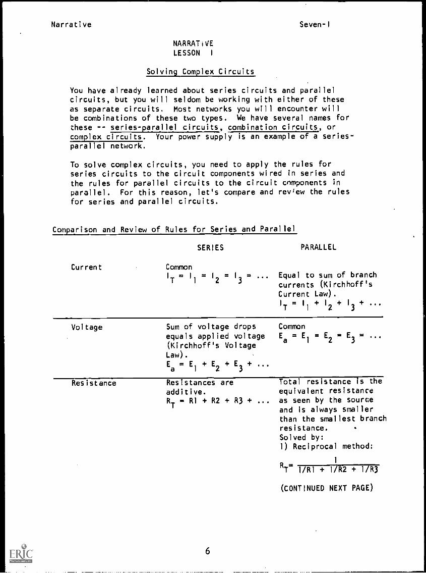
You have already learned about series circuits and parallelcircuits, but you will seldom be working with either of theseas separate circuits. Most networks you will encounter willbe combinations of these two types. We have several names forthese -- series-parallel circuits, combination circuits, orcomplex circuits. Your power supply is an example of a series-parallel network.
To solve complex circuits, you need to apply the rules forseries circuits to the circuit components wired in series andthe rules for parallel circuits to the circuit components in
parallel. For this reason, let's compare and rev'ew the rulesfor series and parallel circuits.
Comparison and Review of Rules for Series and Parallel
Current
SERIES PARALLEL
CommonI
T= 1
1
= I
2= 13 = ... Equal to sum of branch
currents (Kirchhoff'sCurrent Law).IT = 1
1
+ I
2+ 13 +
Voltage Sum of voltage drops Common
equals applied voltage Ea = El = E2 = E3 =
(Kirchhoff's Voltage
Law).Ea = El + E2 + E3 +
Resistance Resistances are Total resistance is the
additive. equivalent resistance
RT
RI + R2 + R3 + ... as seen by the sourceand is always smallerthan the smallest branchresistance.Solved by:
1) Reciprocal method:
6
1
RT 1/R1 + 1/R2 + 1/R3
(CONTINUED NEXT PAGE)
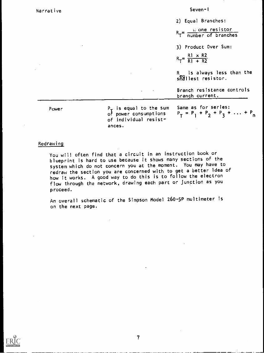
Narrative Seven-I
2) Equal Branches:
s. one resistorRT number of branches
3) Product Over Sum:
RI x R2RT=
RI + R2
R is always less than thesilliest resistor.
Branch resistance controlsbranch current.
Power
Redrawing
P is equal to the sum Same as for series:
of power consumptions PT = P1 + P2 + P3 + + Pn
of individual resist-ances.
You will often find that a circuit in an instruction book or
blueprint is hard to use because it shows many sections of the
system which do not concern you at the moment. You may have to
redraw the section you are concerned with to get a better idea of
how it works. A good way to do this is to follow the electron
flow through the network, drawing each part or junction as you
proceed.
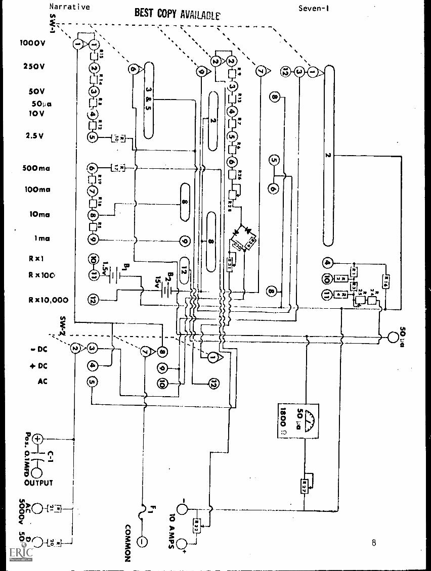
An overall schematic of the Simpson Model 260-5P multimeter is
on the next page.
7
/
zR
13R
3)-'4
5,
tij1
C2
ip
t0.
1
C1
CV
t.i"C
O)
LLiC
12
1
R I S
R 1
Oaz)
501.10
3 & 5
4 -0
Pi\da®-.7
fa,e
SW-1
00
R 3 I
111 82
/7\50 10
1
1800ni
/
liTrf
R19
R 11
RS
6 rE 7
0 a 0 1011
In00In
00S
W-7 44,
O0
'IL
PU
aa
0<
EE
00
ct
C'l
iMis.oM
Pos. 0.1MFD
0
CO
10 A M
PS
11
CO
MM
ON
7AC
5000v0D
C5000v
Narrative Seven-I
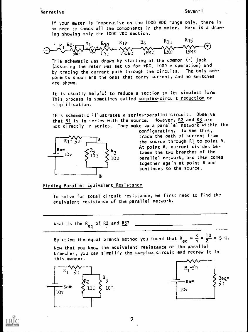
If your meter is inoperative on the 1000 VDC range only, there is
no need to check all the components in the meter. Here is a draw-
ing showing only the 1000 VDC section.
R27 M1 R10 R12 R8 R14 R15
k.: 47,! 150ks! .13/C! MS2 15V1
This schematic was drawn by starting at the common (-) jack
(assuming the meter was set up for +DC, 1000 v operation) and
by tracing the current path through the circuits. The only com-
ponents shown are the ones that carry current, and no switches
are shown.
It is usually helpful to reduce a section to its simplest form.
This process is sometimes called complex-circuit reduction or
simplification.
This schematic illustrates a series-parallel circuit. Observe
that RI is in series with the source. However, R2 and R3 are
not directly in series. They make up a parallel network within theconfiguration. To see this,trace the path of current from
R1= the source through RI to point A.
10v
At point A, current divides be-
1823 tween the two branches of the
10s/ parallel network, and then comestogether again at point B andcontinues to the source.
Finding Parallel Equivalent Resistance
To solve for total circuit resistance, we first need to find the
equivalent resistance of the parallel network.
What is the Req
of R2 and R3?
1
By using the equal branch method you found that Req n
R= = 5 Q.
2
0Q
Now that you know the equivalent resistance of the parallel
branches, you can simplify the complex circuit and redraw it in
this manner: MNR1=52
3
10'1
9
Ea=
lOv
Req=

Narrative Seven-1
Notice that the R in the reduced circuit represents theequivalent resistance of the parallel branches. Now the com-bination circuit has been simplified to a series circuit withtwo resistances.
Finding Total Resistance
You can further reduce the circuit to a circuit with one resistance.This can be accomplished by adding the two resistances in series to
combine them into one representative resistance value, which istotal resistance of the complex circuit -- 10 ohms.
R
1
R1=5 ;,
Ea= eq (1). Ea= fiteq(2)..
10v Scz 10v 1052
You have now redrawn the complex circuit twice.
Once the circuit is reduced to its simplest form, it is a simplematter to solve a series-parallel circuit for other values.
What is I
Tfor the circuit above?
Ee
By Ohm's Law, you found that IT = la
T
Observe that you have taken three steps toward solving for quantitiesin the complex circuit.
1. Find R of the parallel network and redraw the circuit toreflectqR .
2. Find totaTgresistance and reduce circuit to its simplest form.3. Find total current by using Ohm's Law.
See if you can follow the three steps to solve for total currentin the series-parallel circuit below.
R1=5(.2
Ea=
15v
R4=59.
10
=10Q.
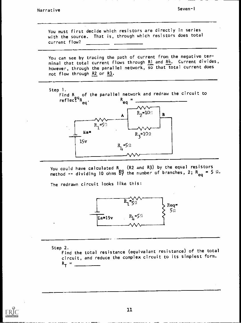
Narrative Seven-1
You must first decide which resistors are directly in series
with the source. That is, through which resistors does total
current flow?
You can see by tracing the path of current from the negative ter-
minal that total current flows through RI and R4. Current divides,
however, through the parallel network, so that total current does
not flow through R2 or R3.
Step 1.Find R of the parallel network and redraw the circuit to
reflectqReq
R =eq
Eau
T15v
I
AR2=100
R3=10',1
You could have calculated R (R2 and R3) by the equal resistors
method -- dividing 10 ohms 69 the number of branches, 2; Req
= 5 Q.
The redrawn circuit looks like this:
Ea=1.5v
Req=
5n
Step 2.Find the total resistance (equivalant resistance) of the total
circuit, and reduce the complex circuit to its simplest form.
RT
=
11
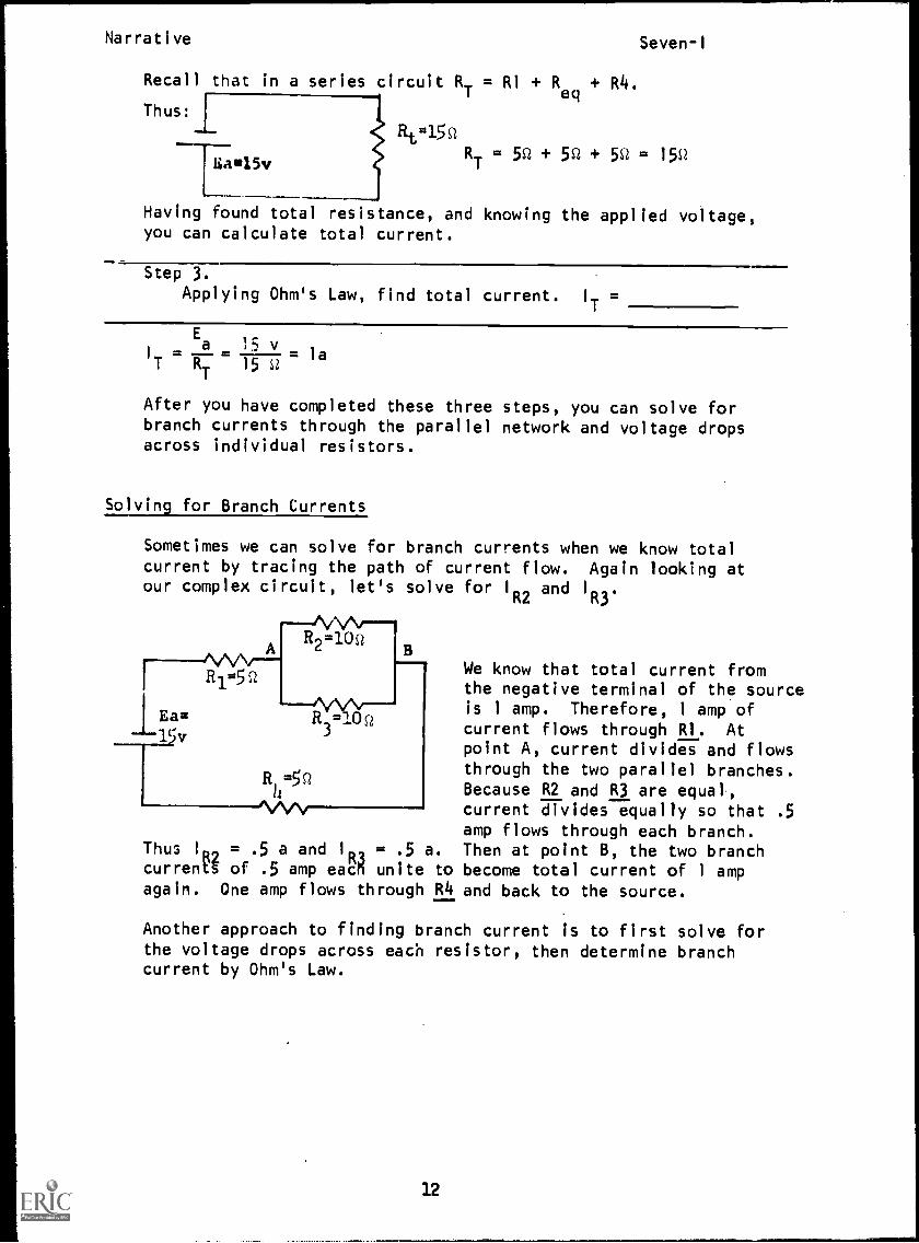
Narrative Seven-I
Recall that in a series circuit RT
= RI Req
+ R4.
Thus:i
Ha15v
ReisRT
= 5Q .4. 5Q .4. 50 = 150
Having found total resistance, and knowing the applied voltage,you can calculate total current.
Step 3.
Applying Ohm's Law, find total current. I
T=
E
1 = = = laT R
T15
After you have completed these three steps, you can solve forbranch currents through the parallel network and voltage dropsacross individual resistors.
Solving for Branch Currents
Sometimes we can solve for branch currents when we know totalcurrent by tracing the path of current flow. Again looking atour complex circuit, let's solve for IR2 and I
R3.
We know that total current fromthe negative terminal of the sourceis 1 amp. Therefore, 1 amp ofcurrent flows through RI. At
point A, current divides and flowsthrough the two parallel branches.Because R2 and R3 are equal,current divides equally so that .5amp flows through each branch.
Thus I
R2= .5 a and I = .5 a. Then at point B, the two branch
currents of .5 amp eacn unite to become total current of 1 ampagain. One amp flows through R4 and back to the source.
Another approach to finding branch current is to first solve forthe voltage drops across each resistor, then determine branchcurrent by Ohm's Law.
12
Narrative Seven-I
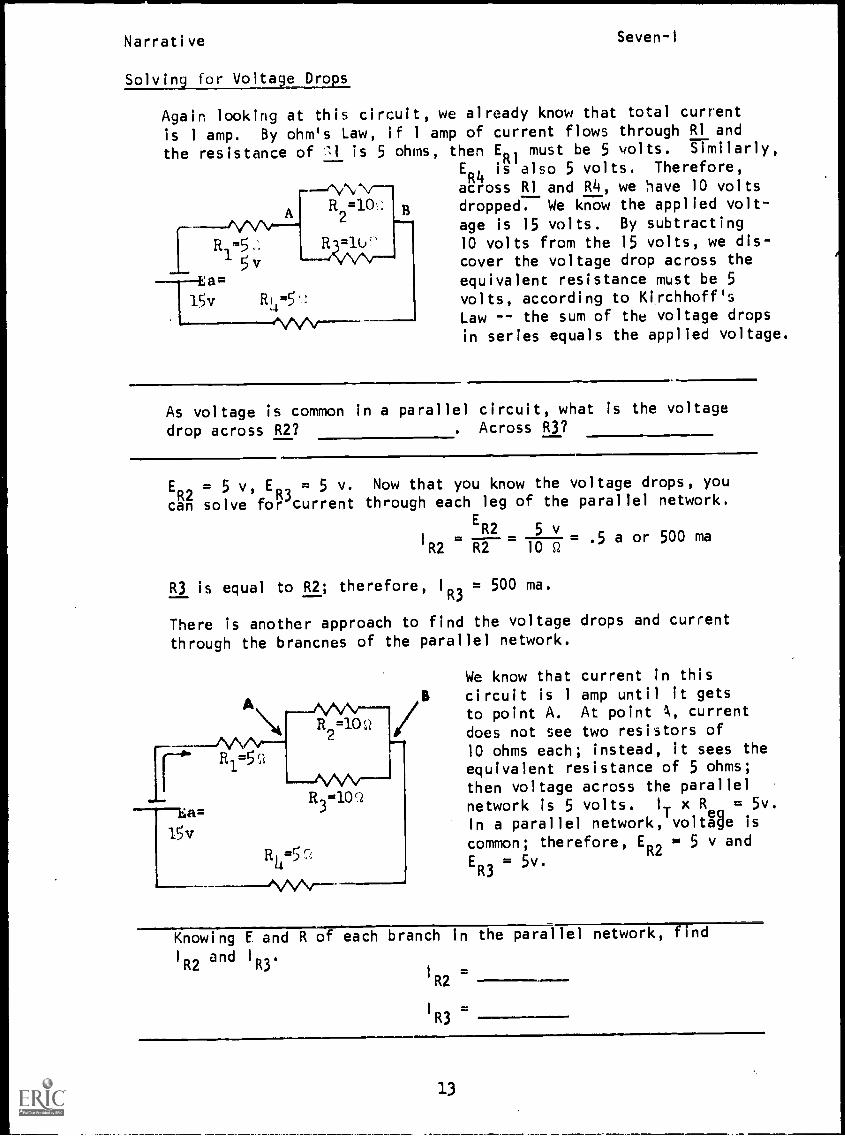
Solving for Voltage Drops
Again looking at this circuit, we already know that total current
is 1 amp. By ohm's Law, if 1 amp of current flows through RI and
the resistance of 11 is 5 ohms, then ER1
must be 5 volts. Similarly,,
ER4
is also 5 volts. Therefore,
- --(\,/ '., N/ across RI and R4, we have 10 volts
AR2=10. dropped. We know the applied volt-
11
M/R
2 is 15 volts. By subtracting
R1=5-
R-411\r-j'-~
10 volts from the 15 volts, we dis-
5v cover the voltage drop across the
--Ea= equivalent resistance must be 5
15v R24 =5 ! volts, according to Kirchhoff's
'MN",Law -- the sum of the voltage dropsin series equals the applied voltage.
As voltage is common in a parallel circuit, what is the voltage
drop across R2? . Across R3?
ER2
= 5 v, ER3
= 5 v. Now that you know the voltage drops, you
can solve for current through each leg of the parallel network.
R2
ER v
=R2
2 =10
5= .5 a or 500 ma
12
R3 is equal to R2; therefore, 1R3 = 500 ma.
There is another approach to find the voltage drops and current
through the brancnes of the parallel network.
We know that current in thiscircuit is 1 amp until it gets
to point A. At point A, current
does not see two resistors of10 ohms each; instead, it sees theequivalent resistance of 5 ohms;
then voltage across the parallelnetwork is 5 volts. IT x R
ea= 5v.
In a parallel network, voltage iscommon; therefore, ER2 = 5 v and
ER3
= 5v.
Knowing E and R of each branch in the parallel network, find
I
R2and I
R3.
1
R2
1 R3=
13
Narrative Seven-I
By using a different approach, you have again four,d that IR2 andI
R3are each .5 amps.
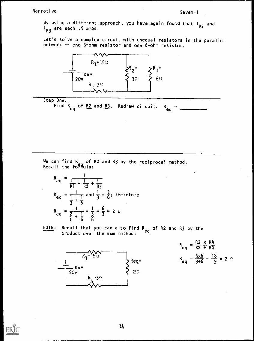
Let's solve a complex circuit with unequal resistors in the parallelnetwork -- one 3-ohm resistor and one 6-ohm resistor.
R1..15
Eau20v
lit1=Y
Step One,Find R
eqof R2 and R3. Redraw circuit. R
eq=
We can find R of R2 and R3 by the reciprocal method.Recall the foMula:
1
Req 1
RI R2 R3
R __L__ 1 2and 3 = iv therefore
R = 1 - 1 6 neq 2 1 3 3 "
NOTE: Recall that you can also find R of R2 and R3 by theproduct over the sum method: eq
R1 n
,Eas20v
R .32
114
R2 x R4eq R2 R
Recr eq 3714 9
3x6 182
2 cz
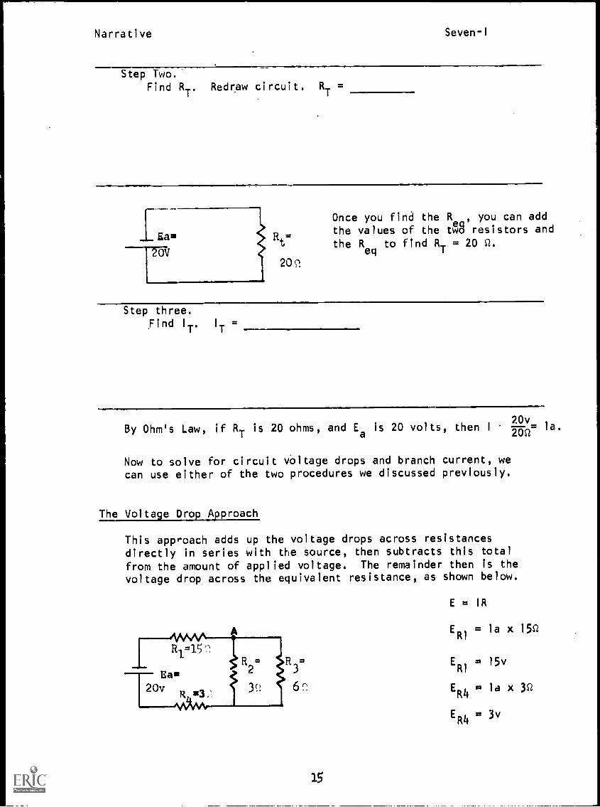
Narrative Seven-I
Step Two.Find RT. Redraw circuit. R
T=
Lan20'V
Rt=
209.
Once you find the Re , you can add
the values of the tw8 resistors andthe 11
eqto find R
T= 20 0.
Step three.
Find I1 I
T
By Ohm's Law, if RT is 20 ohms, and Ea is 20 volts, then I 20v2= la.
Now to solve for circuit voltage drops and branch current, wecan use either of the two procedures we discussed previously.
The Voltage Drop Approach
This approach adds up the voltage drops across resistancesdirectly in series with the source, then subtracts this total
from the amount of applied voltage. The remainder then is thevoltage drop across the equivalent resistance, as shown below.
3
6
E = IR
ERI
= la x 150
ERI
= 15v
ER4
= la x 3c2
ER4
= 3v
Narrative Seven-I
ER I+ ER4
= 15v + 3v = 18v
Ea= 20v; thus 20v 18v = 2v drop across R
eq.
Voltage is common in a parallel network: ER2 is 2 volts; there-fore, E
R3is 2 volts. Then we can find branch currents in this
manner.
Current through R2:
Current through R3:
I
E , 2v= 1or
R R2 3s
R2.667a or 667ma
I
R3= = .3a or 333 ma
W
The alternative approach solves first for voltage across theequivalent resistance, then accordingly solves for branch currentsin the parallel network.
Here, current sees the equivalentresistance of the parallel circuit --2 ohms. Voltage across
Req
= E = IR
E= la x 2Q
E = 2v
Thus, the voltage drop across R2 is 2 volts and across R3 is 2 volts.
Then you can figure current through the resistors in parallel:
I
R2
2v= = 667 ma
2vI
R3= 333ma
los-2
As you can see, using either method, we can solve the complexcircuits.
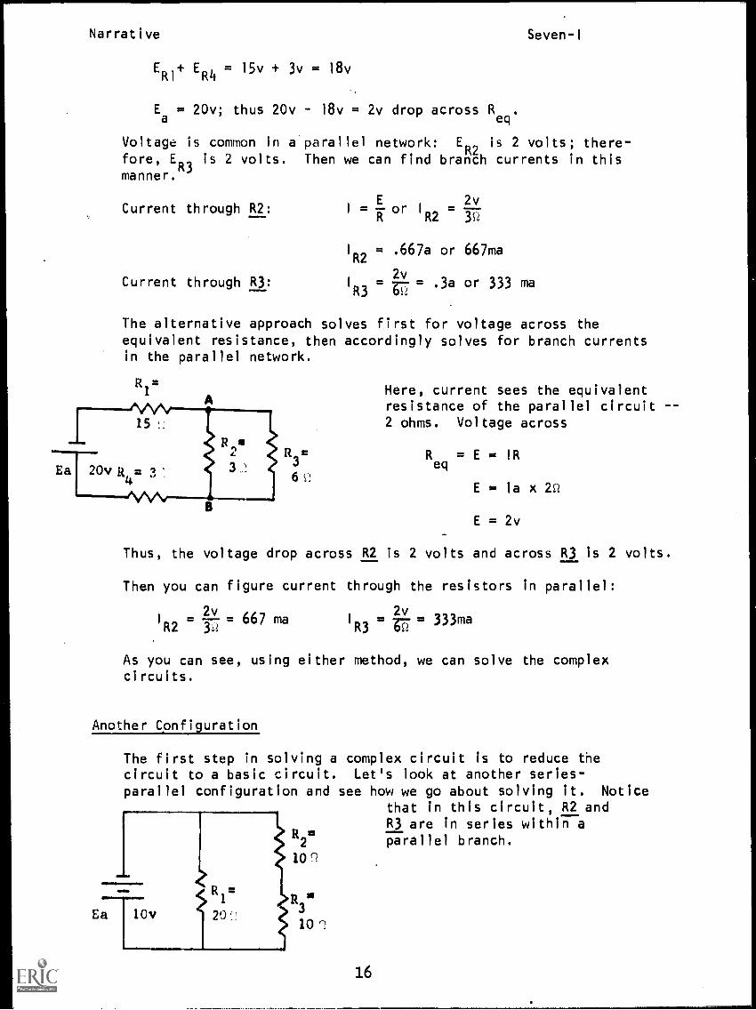
Another Configuration
The first step in solving a complex circuit is to reduce thecircuit to a basic circuit. Let's look at another series-parallel configuration and see how we go about solving it. Notice
that in this circuit, R2 andR3 are in series within a
R2= parallel branch.
10r
R1=
..6.
1TEa 10v 20:3
10 n
16
Narrative Seven-I
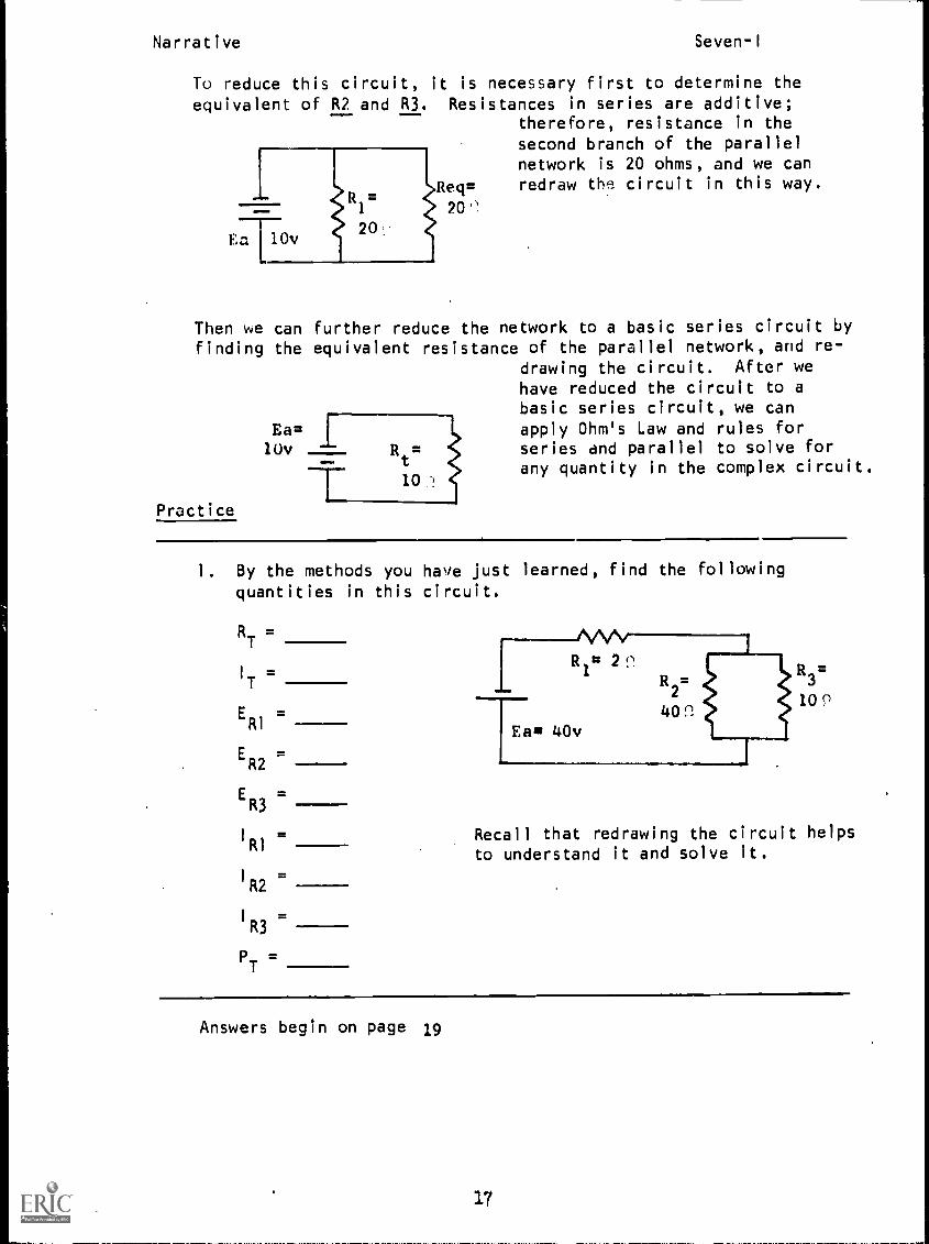
To reduce this circuit, it is necessary first to determine the
equivalent of R2 and R3. Resistances in series are additive;therefore, resistance in thesecond branch of the parallelnetwork is 20 ohms, and we can
Req= redraw the circuit in this way.
"1 20"
Then we can further reduce the network to a basic series circuit byfinding the equivalent resistance of the parallel network, and re-
drawing the circuit. After wehave reduced the circuit to abasic series circuit, we can
Ea= I apply Ohm's Law and rules for10v R
t= series and parallel to solve for
10any quantity in the complex circuit.
Practice
1. By the methods you have just learned, find the followingquantities in this circuit.
RT
=
I
T=
ERI
=
ER2
=
ER3
=
IRI =
I
R2=
I
R3=
PT
Recall that redrawing the circuit helpsto understand it and solve it.
Answers begin on page 19
17
Narrative
Practice
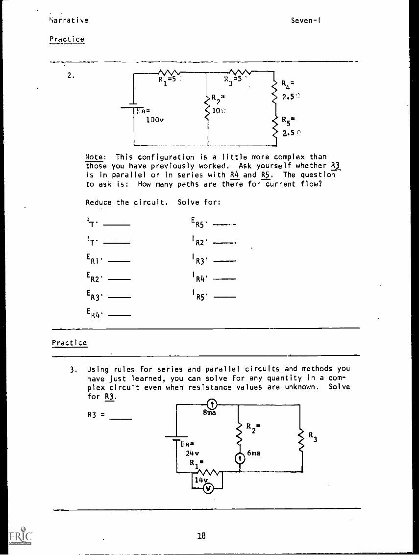
Seven-I
2. R =51
Ea=100v
R_=
R=10%-:
R4=
R5=
2.52.
Note: This configuration is a little more complex thanthose you have previously worked. Ask yourself whether R3is in parallel or in series with R4 and R5. The question
to ask is: Now many paths are there for current flow?
Reduce the circuit. Solve for:
RT. ER5.
IT' I R2 ---ER1' IR3*
ER2' IR4'
ER3.IR5'
ER4'
Practice
3. Using rules for series and parallel circuits and methods youhave just learned, you can solve for any quantity in a com-plex circuit even when resistance values are unknown. Solve
for R3.
R3 =
18
Narrative Seven-1
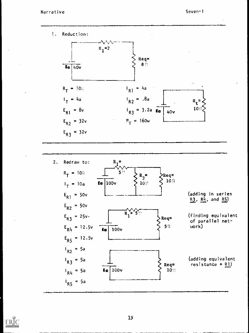
1. Reduction:
Ea 140v
R1=2
Req=8
RT
= 10 1
R1= 4a
I
T= 4a 1
R2= .8a
ER1
= 8v I
R3= 3.2a
ER2
= 32v PT = 160w
ER3
= 32v
Ea 40v
2. Redraw to:
RT
= 10c:
1
T= 10a
ER1
= 50v
ER2
= 50v
ER3
= 25v-
ER4
= 12.5v
ER5
= 12.5v
1
R2= 5a
I
R3= 5a
I
R4= 5a
R5= 5a
R1
5
Ea 100v 102
Ea 100v
1Ea 100v
Req=10C2
(adding in seriesR3, R4, and R5)
Req=
5Q
Req=
(finding equivalent
of parallel net-work)
(adding equivalentresistance + R1)
19
Narrative Seven-I
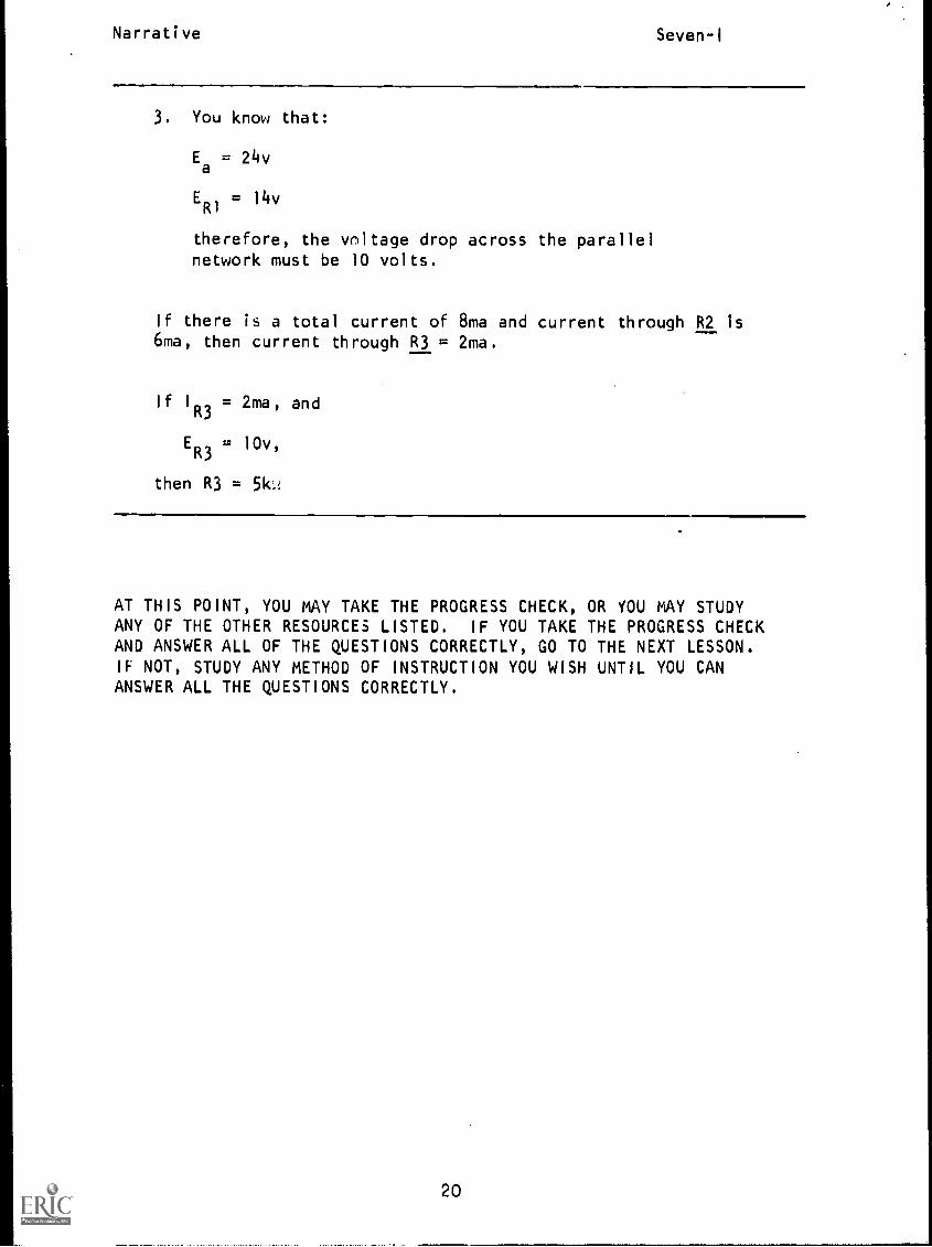
3. You know that:
Ea= 24v
ER) = 14v
therefore, the voltage drop across the parallelnetwork must be 10 volts.
If there is a total current of 8ma and current through R2 is6ma, then current through R3 = 2ma.
If I
R3= 2ma, and
ER3
= 10v,
then R3 = 51c,
AT THIS POINT, YOU MAY TAKE THE PROGRESS CHECK, OR YOU MAY STUDYANY OF THE OTHER RESOURCES LISTED. IF YOU TAKE THE PROGRESS CHECKAND ANSWER ALL OF THE QUESTIONS CORRECTLY, GO TO THE NEXT LESSON.IF NOT, STUDY ANY METHOD OF INSTRUCTION YOU WISH UNTIL YOU CANANSWER ALL THE QUESTIONS CORRECTLY.
20
P.I. Seven-I
PROGRAMMED INSTRUCTIONLESSON I
Solving Complex Circuits
TEST FRAMES ARE 17, 34, AND 38. AS BEFORE, GO FIRST TO TEST FRAME
17 AND SEE IF YOU CAN ANSWER ALL THE QUESTIONS THERE. FOLLOW THE
DIRECTIONS GIVEN AFTER THE TEST FRAME.
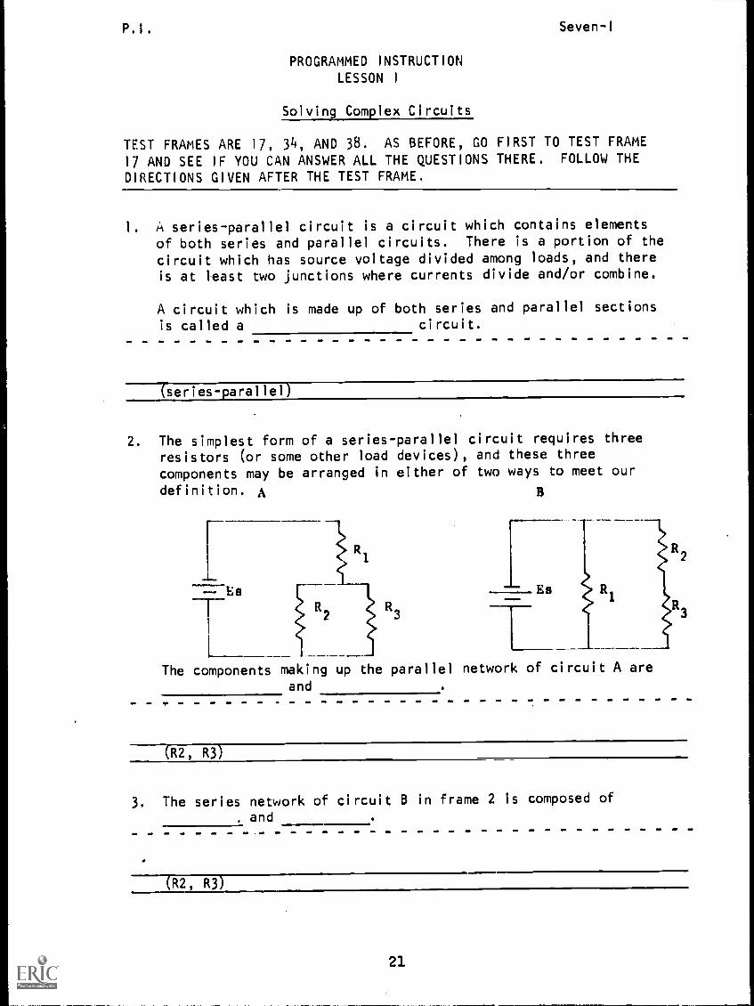
1. A series-parallel circuit is a circuit which contains elements
of both series and parallel circuits. There is a portion of the
circuit which has source voltage divided among loads, and thereis at least two junctions where currents divide and/or combine.
A circuit which is made up of both series and parallel sectionsis called a circuit.
(series-parallel)
2. The simplest form of a series-parallel circuit requires threeresistors (or some other load devices), and these threecomponents may be arranged in either of two ways to meet our
definition. A
=Es
The components making up the parallel network of circuit A areand
(R2 , R3)
3. The series network of circuit B in frame 2 is composed of
. and
(R2, R3)
P.I. Seven-I
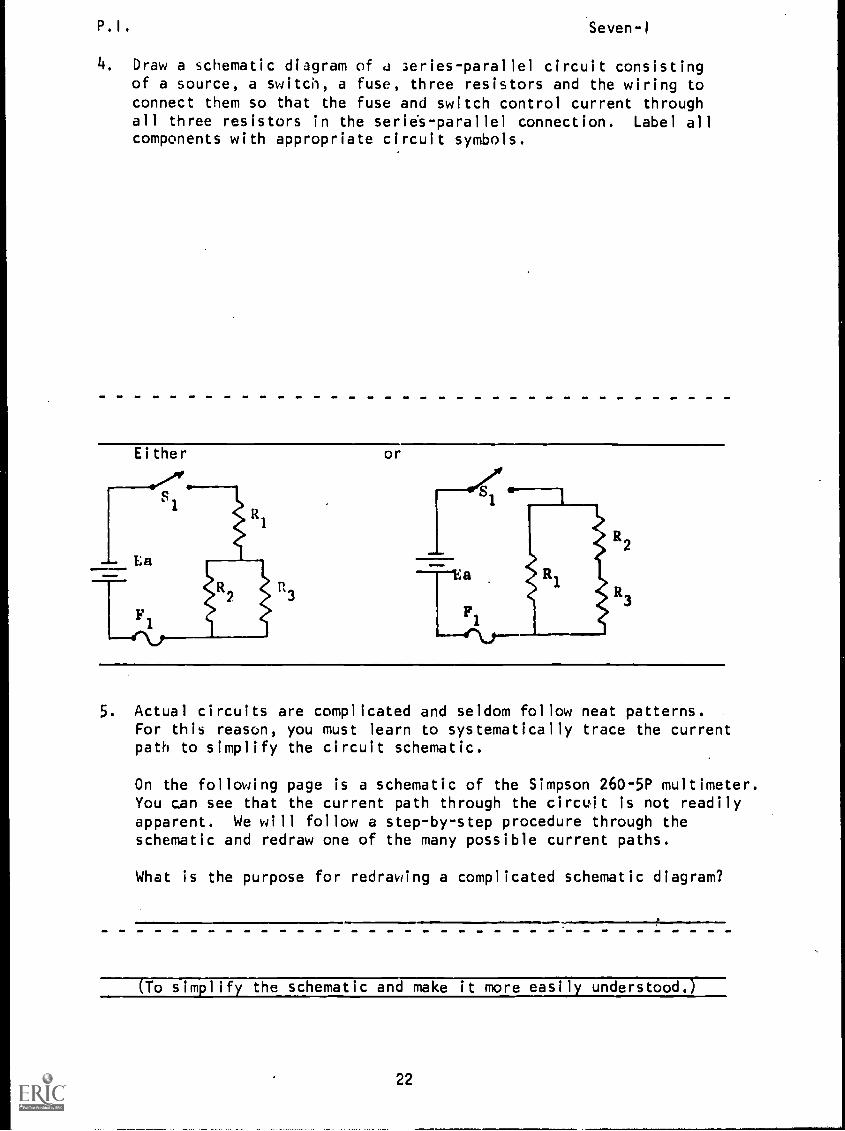
4. Draw a schematic diagram of a aeries- parallel circuit consistingof a source, a switch, a fuse, three resistors and the wiring toconnect them so that the fuse and switch control current throughall three resistors in the series-parallel connection. Label allcomponents with appropriate circuit symbols.
or
5. Actual circuits are complicated and seldom follow neat patterns.For this reason, you must learn to systematically trace the currentpath to simplify the circuit schematic.
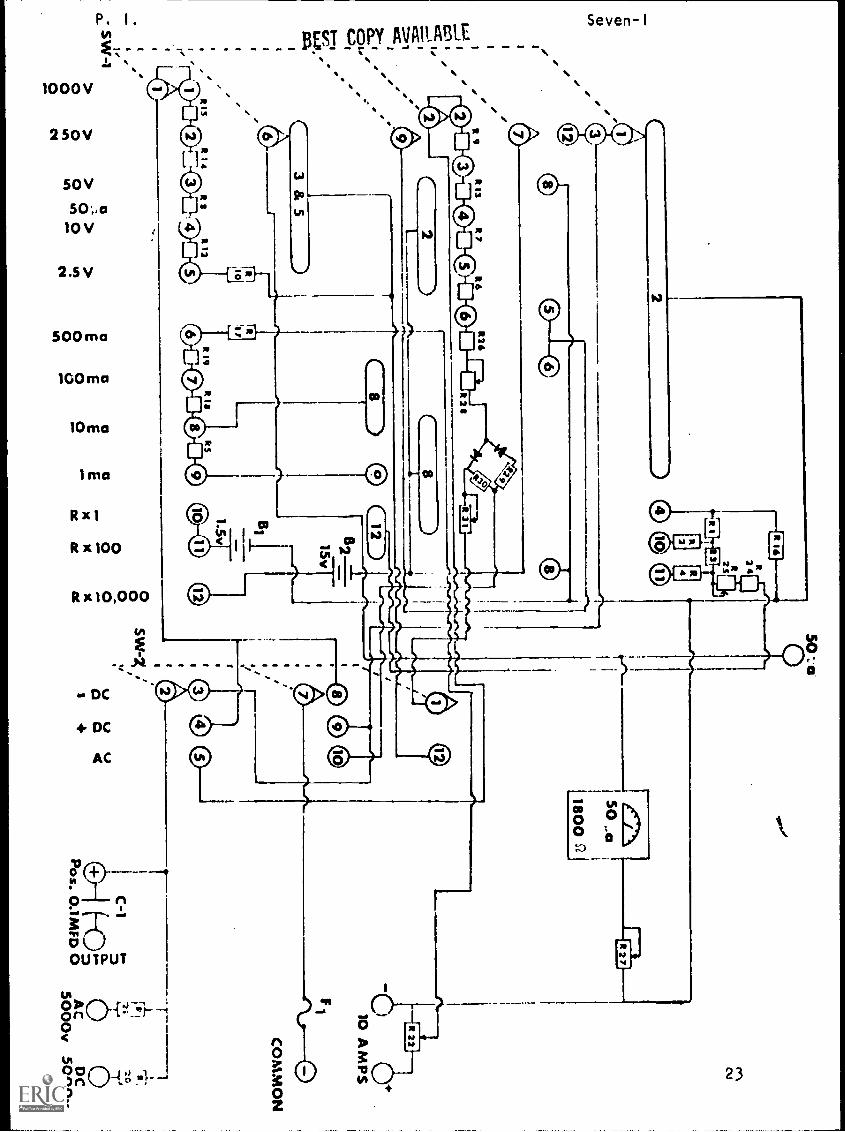
On the following page is a schematic of the Simpson 260-5P multimeter.You can see that the current path through the circuit is not readilyapparent. We will follow a step-by-step procedure through theschematic and redraw one of the many possible current paths.
What is the purpose for redrawing a complicated schematic diagram?
(To simplify the schematic and make it more easily understood.
22
CC./1
e
2
312
14.1
a) A
AC
CI
ee
(=N
It IS
AR
A
R7
5
0
R6
R2
souK
m
O1111111Menim
0
12
A
SW..1
0
Rts0
a s4
R12
0
R2*
RI
R31
10
24R2sa)
0
MO
MLR
19R
1aits
6 a on8 0
8
aa
a>
o>
EE
oo
o0
0in
141vs
'1C
lC
l0
01e1
aa
6215v
1.5v
10a)
41)
50 a0
se-I1A1 50
"a
t800
b.
A000
SW -X
'0
00,
oci
v v vx
x;
0 oqx
ata
gig1
4
rem
10 A M
ps
F
CO
MM
ON
it Ia
C-1
N2;
2.
f-01Pos. 0.1M
FD 0
DC
5000v
P. I . Seven-I
6. Look at the schematic in frame 5. At the bottom you see thepositions of both the Range Selector (SW1) and the FunctionSwitch (SW2). Directly above the 1000 v and the -DC positionsyou see a number of switch contacts represented by and con-nected by dotted lines.
When the switch position is changed, the contacts ganged by thedotted lines move in the same direction at the same time. The
schematic indicates both switches in the fully counterclockwiseposition.
Rotate the Function Switch one position clockwise and list thenumbers of the contacts moved and the direction moved (left orright).
(Contacts 1, 7, and 2 each move one position to the right.)
7. One more thing about the switch contacts and we will get started.
The switch contacts designated by e.5 are movable, you see contactsdesignated by 0 or( ), these contacts remain stationary asthe switch position is changed. Note that the movable contacts
touch different stationary contacts when the switch is moved.
Indicate by number the movable contacts of the Range Selector inthe 1000 v position and the non-moving contacts which they touch.
(1,3 and 12 touch 2; 7 touches none; 2 touches 2; 9 touches none;6 touches 3 and 5, 1 touches 1)
8. All of this simply means that if two switch contacts are touching,current can flow from one to the other.
In frame 6, the function switch was rotated clockwise, to the +DC
position. Indicate by number the movable contacts and the contactsthey touch.
(1 touches none; 7 touches 9; 2 touches 4)
(Remember this because as we go through the schematic the !unction
Switch is to be in the +DC position.)
214
P.I. Seven-I
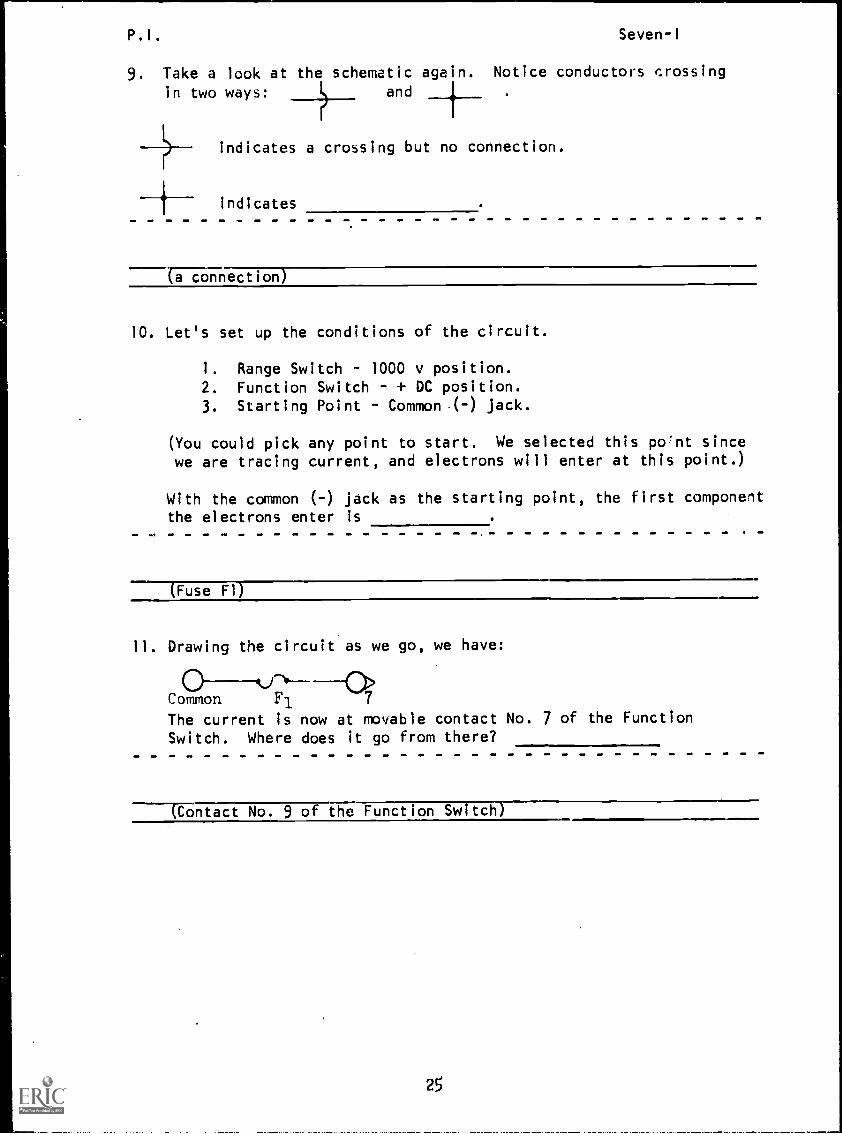
9. Take a look at the schematic again. Notice conductors crossing
in two ways: and
indicates a crossing but no connection.
indicates
5ZOnnection)
10. Let's set up the conditions of the circuit.
1. Range Switch 1000 v position.
2. Function Switch - + DC position.
3. Starting Point Common.( -) jack.
(You could pick any point to start. We selected this po'nt sincewe are tracing current, and electrons will enter at this point.)
With the common (-) jack as the starting point, the first componentthe electrons enter is
Fuse Fl)
11. Drawing the circuit as we go, we have:
(gkr*-------"C>
Common F1 7
The current is now at movable contact No. 7 of the Function
Switch. Where does it go from there?
----Contact No. 9 of the Function Switch)
25
P.I. Seven-I
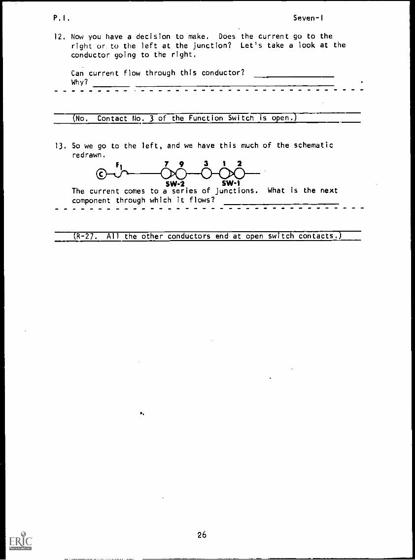
12. Now you have a decision to make. Does the current go to the
right or to the left at the junction? Let's take a look at the
conductor going to the right.
Can current flow through this conductor?Why?
(No. Contact No. 3 of the Function Switch is o en.
13. So we go to the left, and we have this much of the schematic
redrawn.
SVM SVV-1The current comes to a series of junctions. What is the next
component through which it flows?
----1R-27. All the other conductors end at open switch contacts.T----
26
P. I . Seven-I
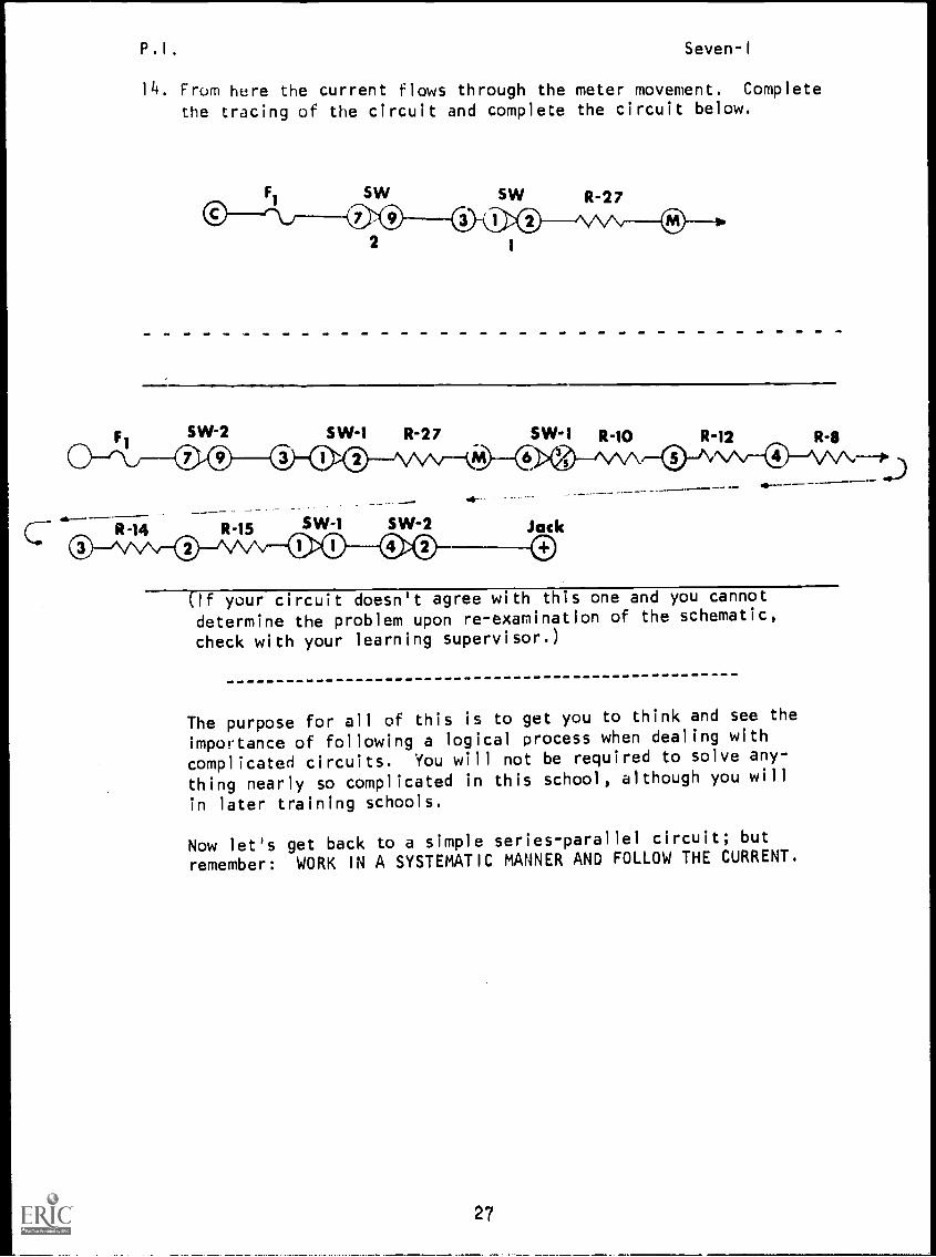
14. From here the current flows through the meter movement. Complete
the tracing of the circuit and complete the circuit below.
Fi SW-2
O--c\j---ri)'
ab-- -R-14 R-15
S W -1
2
SW-1
R-27
SW-2
SW-1 R-10 R-12 R-8
-q"
Jack
®(If your circuit doesn't agree with this one and you cannot
determine the problem upon re-examination of the schematic,
check with your learning supervisor.)
The purpose for all of this is to get you to think and see the
importance of following a logical process when dealing with
complicated circuits. You will not be required to solve any-
thing nearly so complicated in this school, although you will
in later training schools.
Now let's get back to a simple series-parallel circuit; but
remember: WORK IN A SYSTEMATIC MANNER AND FOLLOW THE CURRENT.
27

P.I. Seven-1
15. If the values of all the load devices in a series-parallel groupare known, the value of an equivalent resistor may be found bycombining the methods used for series connections with those usedfor parallel circuits. To further understand this process, followthese steps:
I
113.=
5Q
R2= R3
=
10Q 10 SI
R1=1
5Q
Req=5Q
=Rt
10 S2
First, let's find the equivalentresistance for the parallel por-tion of our circuit.
Re = =q
The circuit can be redrawn toshow R
1
in series with the Req
of R2 and R3 found above. We
can now reduce this series circuitto its equivalent resistance which.is R
T.
RT
You have now found that theresistance is equal to 10 ohms,and we can replace the entireseries-parallel network with a
single equivalent resistanceof 10 ohms.
This is known as complex circuit reduction or simplification.
28
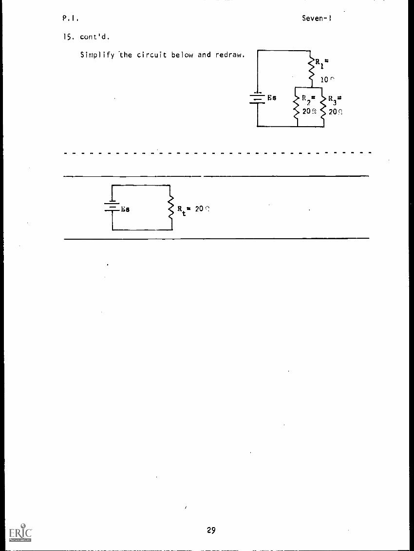
P 4 1 4
15. cont'd.
Simplify the circuit below and redraw,
Seven- I
IR
tag20Q
29
P. I . Seven-1
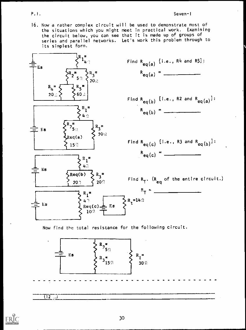
16. Now a rather complex circuit will be used to demonstrate most ofthe situations which you might meet in practical work. Examining
the circuit below, you can see that it is made up of groups of
series and parallel networks. Let's work this problem through to
its simplest form.
R =4
=
5n
R4= R5
60
=Es
1
4
R3=
20 P..
eq(a)
25
20 s2
R3=
15'2
Es
Es
121=.
42
1,11eq(b)
1 202 2(r.Find R
T. (R
eqof the entire circuit.)
Find Req(a)
[i.e., R4 and R5]:
Req(a)
Find R eq(b) (i.e., R2 and R eq(a)1:
Req(b)
Find Req(c)
(i.e., R3 and R eq(b)]:
Req(c) =
42Req(c)"
10C),
RT
t =14 ..Z
Es
Now find the total resistance for the following circuit.
(12 ..)
30
P.I. Seven-I
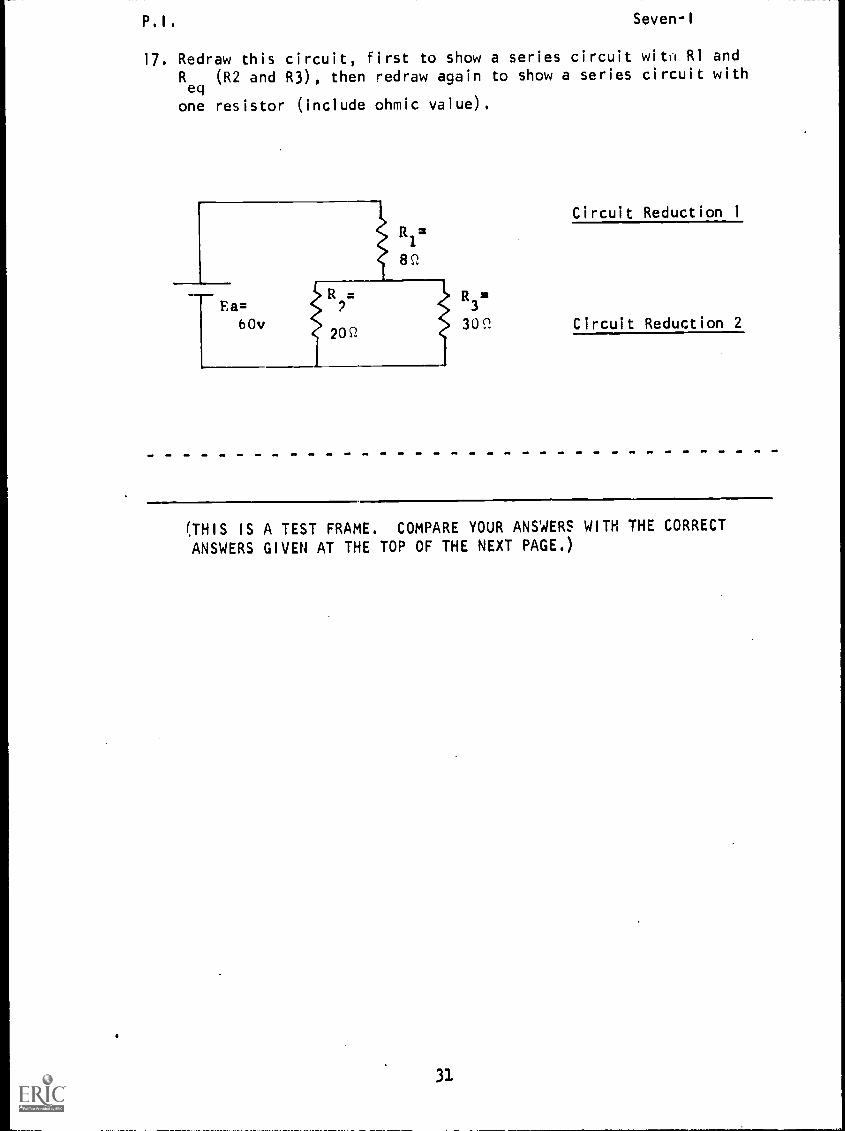
17. Redraw this circuit, first to show a series circuit wito R1 andRey
(R2 and R3), then redraw again to show a series circuit with
one resistor (include ohmic value).
Ea=60v
=1
8P.
Circuit Reduction 1
R3
309, Circuit Reduction 2
(THIS IS A TEST FRAME. COMPARE YOUR ANSWERS WITH THE CORRECT
ANSWERS GIVEN AT THE TOP OF THE NEXT PAGE.)
31
P.I. Seven-I
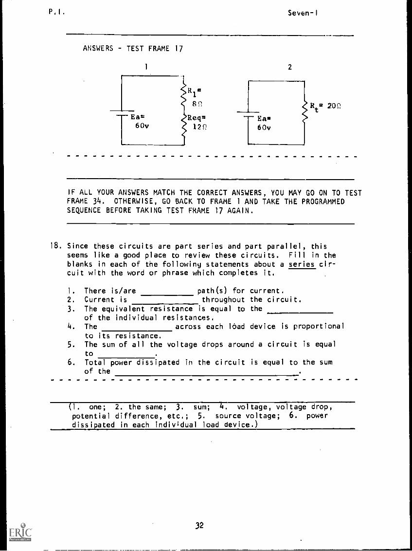
ANSWERS - TEST FRAME 17
1
Eazt
60vReq=
0v 122.
2
20Q
IF ALL YOUR ANSWERS MATCH THE CORRECT ANSWERS, YOU MAY GO ON TO TESTFRAME 34. OTHERWISE, GO BACK TO FRAME 1 AND TAKE THE PROGRAMMEDSEQUENCE BEFORE TAKING TEST FRAME 17 AGAIN.
18. Since these circuits are part series and part parallel, thisseems like a good place to review these circuits. Fill in the
blanks in each of the following statements about a series cir-cuit with the word or phrase which completes it.
1. There is/are path(s) for current.2. Current is throughout the circuit.3. The equivalent resistance is equal to the
of the individual resistances.4. The across each load device is proportional
to its resistance.5. The sum of all the voltage drops around a circuit is equal
to
6. Total power dissipated in the circuit is equal to the sumof the
(1. one; 2. the same; 3. sum; 4. voltage, voltage drop,potential difference, etc.; 5. source voltage; 6. power
dissipated in each individual load device.)
32
P.I.
19. In a parallel circuit:
1. There is/are
Seven-1
current path(s).
2. is the same for each branch of the
circuit.
3. in any branch is inversely pro-
portional to the resistance of the branch.4. Total current equals the sum of the
5. Total resistance equals the reciprocal of the sum of the
reciprocals of the6. Total power dissipated is equal to the sum of the
(1. more than one; 2. voltage or potential difference; 3. current;
4. branch currents; 5. resistances of each branch; 6. power
dissipated by each resistor)
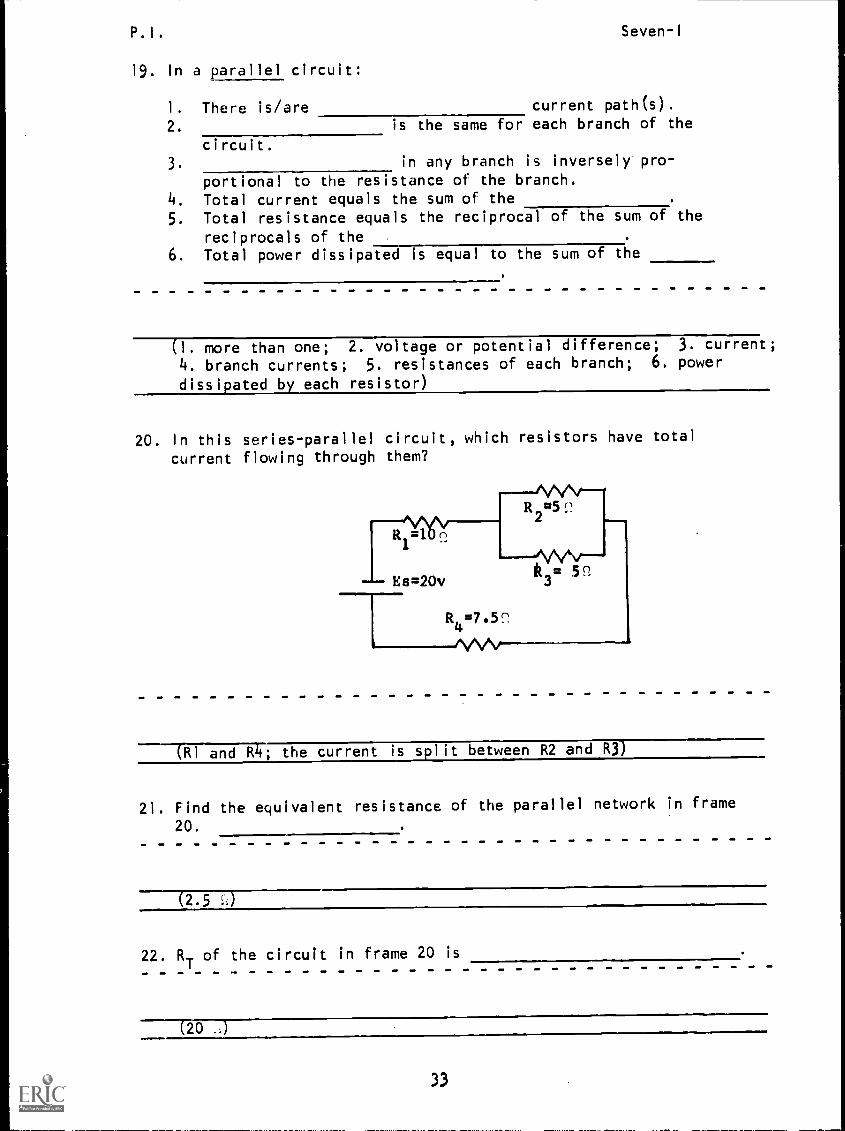
20. In this series-parallel circuit, which resistors have total
current flowing through them?
(R1 and R4; the current is split between R2 and R3)
21. Find the equivalent resistance of the parallel network in frame
20.
(2.5 r..)
22. RTof the circuit in frame 20 is
2033
P. I . Seven-I
23. Since you know Es and RT, find I
Tusing Ohm's Law.
(I a)
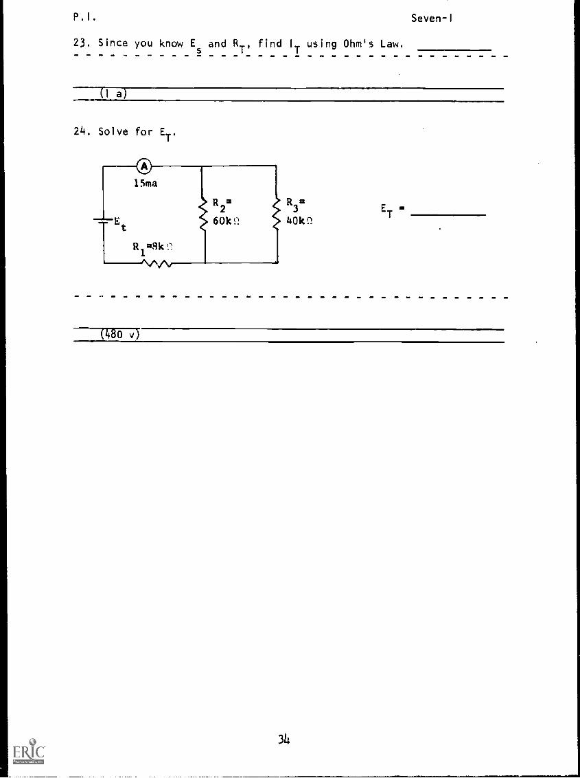
24. Solve for ET'
R3=
ET
=
Ltokn
(480 v)
314
P. I . Seven-1
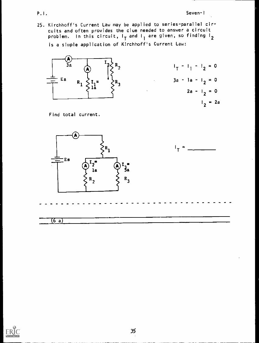
25. Kirchhoff's Current Law may be applied to series-parallel cir-cuits and often provides the clue needed to answer a circuit
problem. In this circuit, IT and 11 are given, so finding 12
is a simple application of Kirchhoff's Current Law:
Find total current.
I
IT =
35

P.I. Seven-I
26. Solve for ER1'
ERI
=
(40 v)
27. Kirchhoff's Voltage Law applies to the series portion of a series-parallel circuit in exactly the same way it applies to a straightseries circuit. In the diagram below, the source voltage isdivided as shown by the brackets El and E2.
-El - E2
= 0
75v - 50v - E2
= 0
E3= 25 v
What will the voltage drop across R3 be? ER2 =
(25 v)
36
P.I. Seven-I
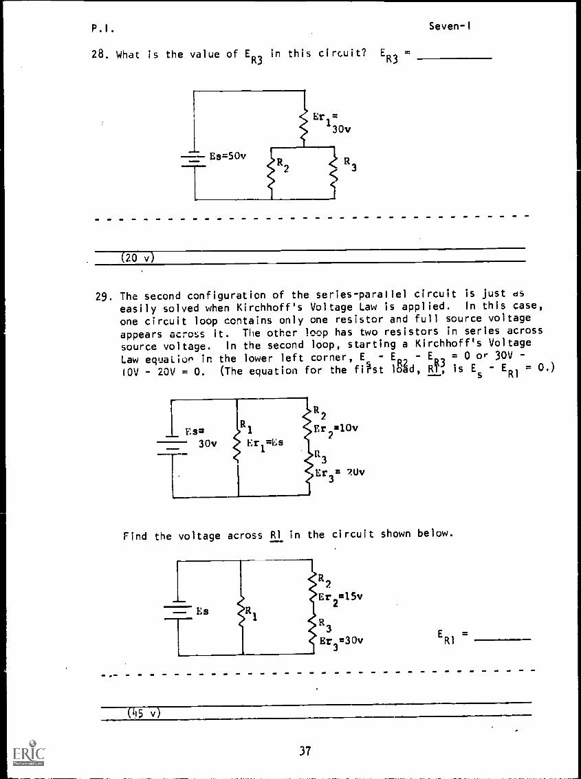
28. What is the value of ER3
in this circuit? ER3
(20 v)
29. The second configuration of the series - parallel circuit is just ds
easily solved when Kirchhoff's Voltage Law is applied. In this case,
one circuit loop contains only one resistor and full source voltage
appears across it. The other loop has two resistors in series across
source voltage. In the second loop, starting a Kirchhoff's Voltage
Law equation in the lower left corner, Es
- ER2
- Ek13
= 0 or 30V -
i0V - 20V = 0. (The equation for the first load, RI, is Es - ER1 = 0.)
R2
I Es=R1
Er2=10v
30v I., r,=Es
--T--
R3
> Er 3= 7.0v
1
Find the voltage across RI in the circuit shown below.
Es
It2
Erg 15v
3
Er3=30v
ERI
=
(L15 v')
37
P. I .
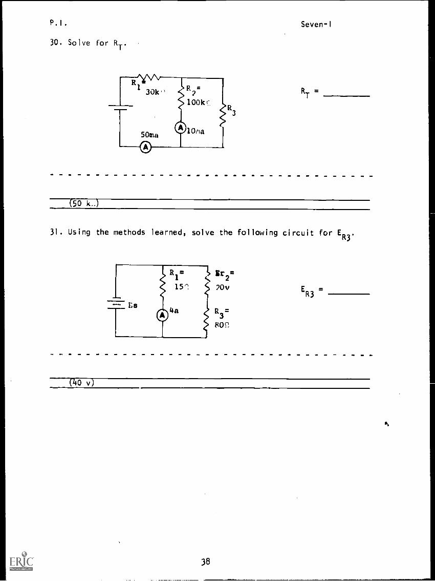
30. Solve for RT.
Seven-I
RT
50 k..)
31. Using the methods learned, solve the following circuit for ER3
.
ER3
(40 v)
38
P. I .
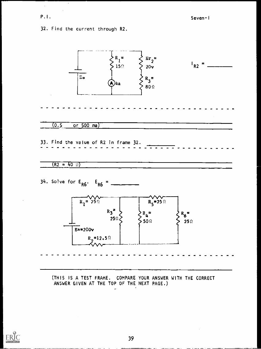
32. Find the current through R2.
Seven-I
R1=
159
E
20v
r2
I
R2
uD R3=
80Q
(0.5 or 500 ma)
33. Find the value of R2 in frame 32.
(R2 = 40 S2)
34. Solve for EER6
=R6'
1\A.A0-R1
25Q
EA=200v
R3'
25P
R2=12.59
1-1\5112..512.
R4= R6=
50 Q 25P.
(THIS IS A TEST FRAME. COMPARE YOUR ANSWER WITH THE CORRECTANSWER GIVEN AT THE TOP OF THE NEXT PAGE.)
39
P.1 Seven -I'
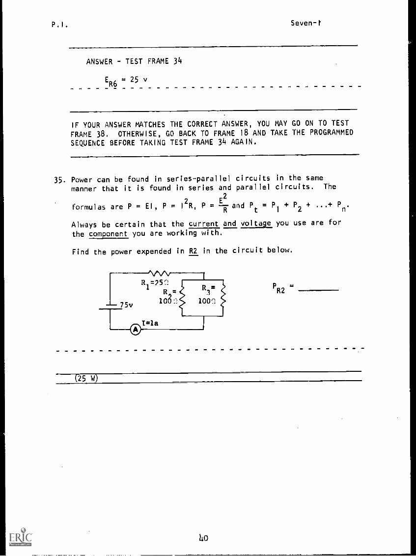
ANSWER - TEST FRAME 34
ER6
= 25 v
IF YOUR ANSWER MATCHES THE CORRECT ANSWER, YOU MAY GO ON TO TEST
FRAME 38. OTHERWISE, GO BACK TO FRAME 18 AND TAKE THE PROGRAMMEDSEQUENCE BEFORE TAKING TEST FRAME 34 AGAIN.
35. Power can be found in series-parallel circuits in the same
manner that it is found in series and parallel circuits. The
E2
formulas are P = El, P = I
2R, P = 7 and Pt = PI + P2 + ...+ Pn.
Always be certain that the current and voltage you use are for
the component you are working with.
Find the power expended in R2 in the circuit below.
PR2=
(25 W)
4o
P. I . Seven-I
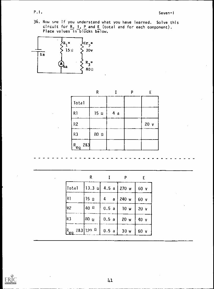
36. Now see if you understand what you have learned. Solve thiscircuit for R, I, P and E (total and for each component).Place values in blocks below.
Er2=
20v
R3=
805
R I P E
Total
RI 15 Si 4 a
R2 20 v
R3 80 Q
Req
2&3
R I P E
Total 13.3 st 4.5 a 270 w 60 v
R1 15 Q 4 a 240 w 60 v
R2 40 Q
80 sz
0.5a 10 w 20v
R3 0.5 a 20 w 40 v
Req
283 1?n Q 0.5 a 30 w 60 v
P.I. Seven-I
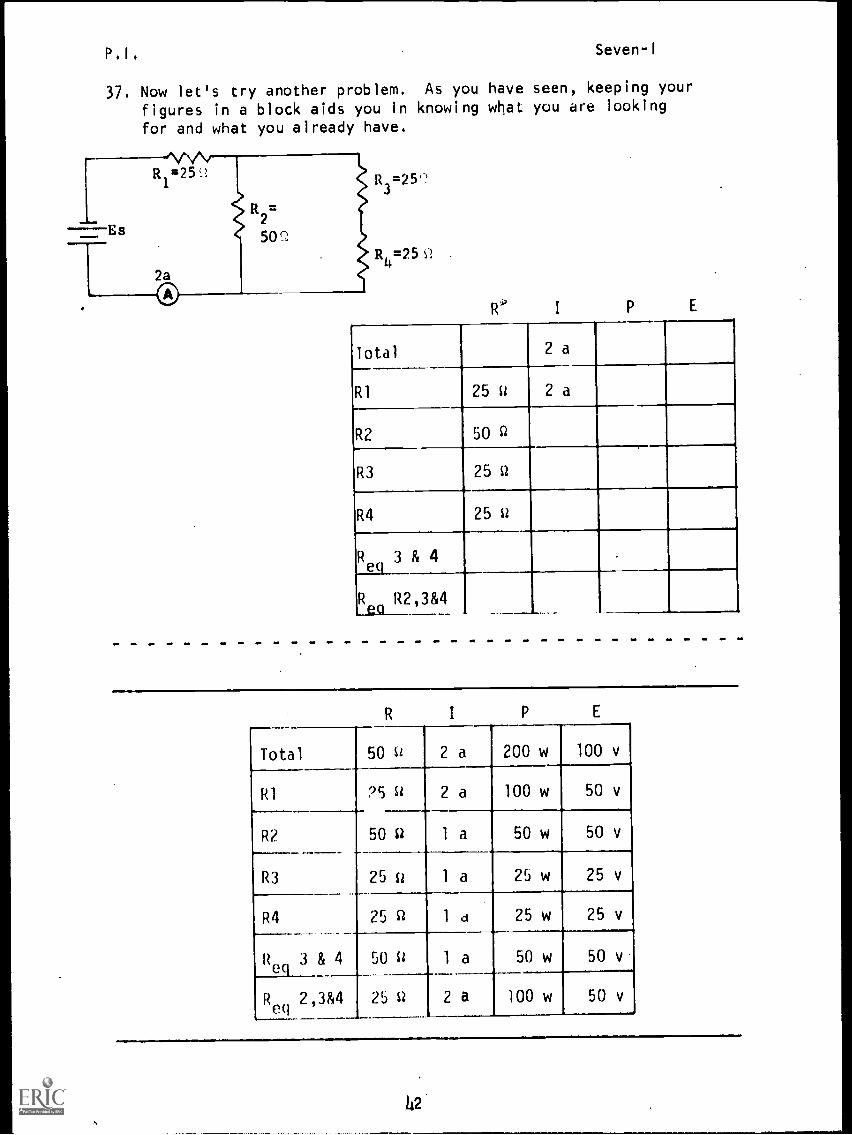
37. Now let's try another problem. As you have seen, keeping your
figures in a block aids you in knowing what you are looking
for and what you already have,
I
Total
R1 25 W
R2 50 R
R3 25 W
R4 25 W
f3Rea
R2,3&4
& 4..___
I E
Total 50 w 2 a 200 w 100 v
R1 25 w 2 a 100 w 50 v
R2 50 a 1 a 50 w 50 v
R3 25 St 1 a 25 w 25 v
R4 25 W 1 d 25 w 25 v
1ef
3& 4 50 W 1 a 50 w 50 v
Reel 2,3&4 25 W 2 a 100 w 50 v
42
P. I .
BEST COPY AVAILABLE
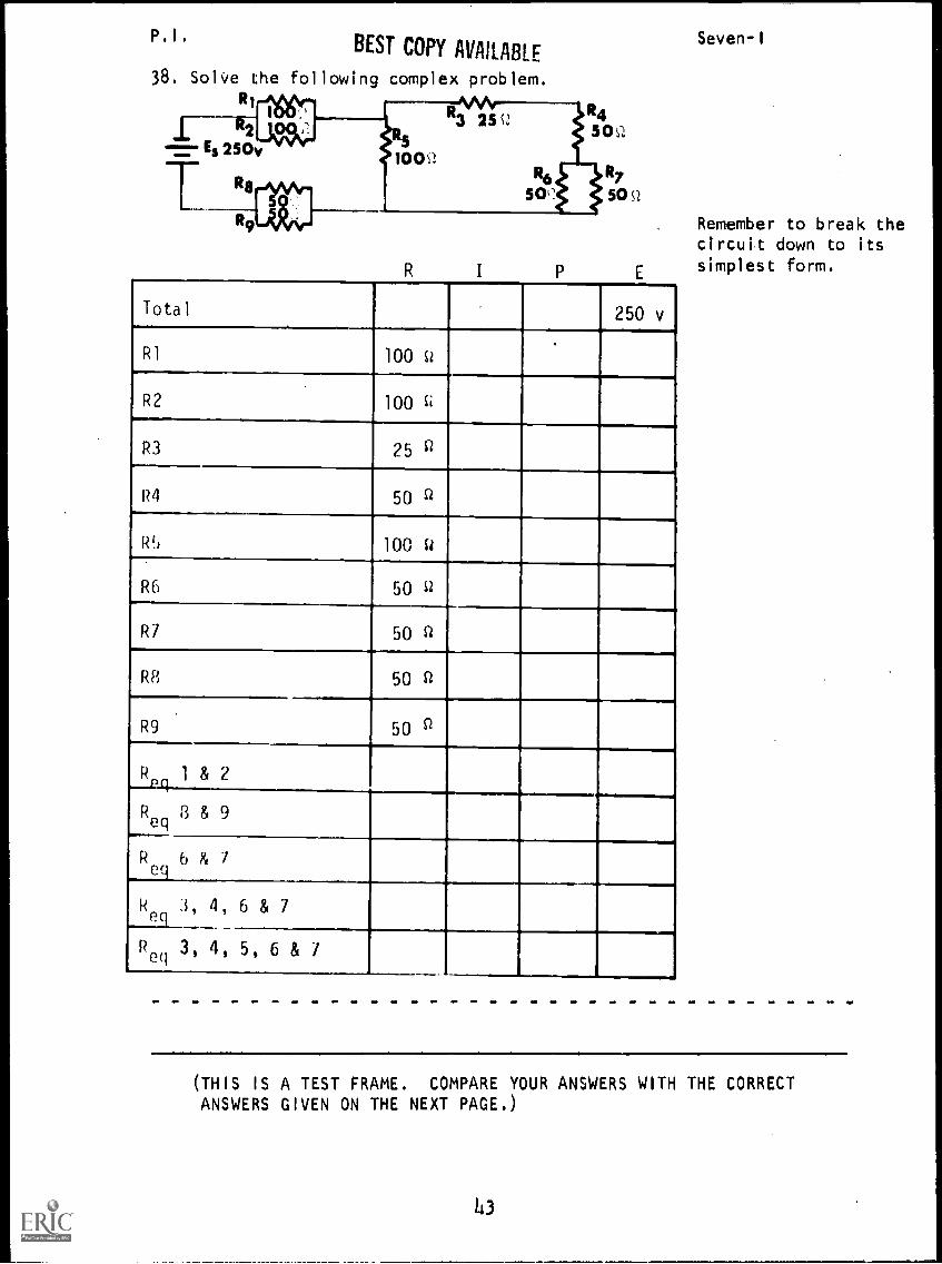
38. Solve the following complex problem.
I R2 jes,-;;.
Es 250v
R I P
Total 250 v
R1 100 U
R2 100 0
R3 25 fl
R4 50
R5 100 W
R6 50 0
R7 50 0
R8 50 0
R9 50 P
241 & 2
Req
8 & 9
R 6 & 7eq
Req
3, 4, 6 & 7
Req
3, 4, 5, 6 & 7
Seven-I
Remember to break thecircuit down to itssimplest form.
(THIS IS A TEST FRAME. COMPARE YOUR ANSWERS WITH THE CORRECTANSWERS GIVEN ON THE NEXT PAGE.)
43
P. I .Seven-I
ANSWERS - TEST FRAME 38
R I E
Total 125 0 2 a 500 w 250 v
R1 100 Q 1 a 100 w 100 v
R2 100 0 1 a 100 w 100 v
R3 25 a 1 a 25 w 25 v
R4 50 0 1 a 50 w 50
R5 100 0 1 a 100 w 100 v
R6 50 0 0.5 a 12.5 w 25 v
R7 5C i 0.5 a 12.5 w 25 v
R8 50 st 1 a 50 w 50 v
R9 50 0 1 a 50 w 50 v
--2.9
R 1 & 2 50 0 2a 200 w 100 v
Reg
8 & 9 25n 2 a 100 w 50V
Reg6 &7 250 1 a 25w 25v
Re q
3, 4, 6 8" 7 100 0 1 a 100 w 100 v
Reg
3, 4, 5, 6& 7 50 0 2 a 200 w 100 v
IF ANY OF YOUR ANSWERS ARE INCORRECT, GO BACK TO FRAME 35 AND TAKE THE
PROGRAMMED SEQUENCE.
IF YOUR ANSWERS ARE CORRECT, YOU MAY TAKE THE PROGRESS CHECK, OR YOU MAY
STUDY ANY OF THE OTHER RESOURCES LISTED. IF YOU TAKE THE PROGRESS CHECK
AND ANSWER ALL THE QUESTIONS CORRECTLY, GO ON TO THE NEXT LESSON. IF NOT,
STUDY ANY METHOD OF INSTRUCTION YOU WISH UNTIL YOU CAN ANSWER ALL THE
QUESTIONS CORRECTLY.
W4

Summary Seven-I
SUMMARY
LESSON I
Solving Complex Circuits
So far you have studied series and parallel circuits. These simple cir-cuits are found in numerous electrical devices. However, in our modernsociety, most networks you will encounter will be more complex; theywill consist of combinations of series and parallel configurations.Complex circuits are also called series-parallel, or combinationcircuits.
In this lesson, we will develop some of the techniques that will en-able you to solve complex circuits. Since most of what we have tobuild on are the rules for series and parallel circuits, let us re-view these important relationships.
In a series circuit, we found that:
I
T= I
1
= I
2= 13 =
Ea = E1
+ E2+ E3 + (Kirchhoff's Voltage
RT= RI + R2 + R3 + ... Law)
However, in a parallel circuit, we found that:
I
T= I
1
+ I
2+ 13 + (Kirchhoff's Current
Ea = E1
E2
= E3 = ... Law)
RT
1 I 1
-rRl
-r -rR2 R3
6
Rn
1
The last relationship simplifies under certain special conditions.We saw that if all of the branch loads are of equal resistance:
resistance of one resistorRT number of branches
We also saw that for a two-branch circuit:
RI x R2RT R1 + R2
We note that in all parallel circuits, Req
is always less than thesmallest resistor.
For both series and parallel circuits, the total power consumed is:
PT = P1
+ P2 + P3 + Pn
.
45
Summary Seven-I
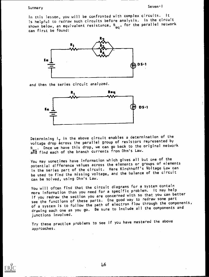
In this lesson, you will be confronted with complex circuits. It
is helpful to redraw such circuits before analysis. In the circuit
shown below, an equivalent resistance, Req
, for the parallel network
can first be found:
and then the series circuit analyzed.
Ea
T
Reg'VVV-
D S-I
DS -1
Determining IT in the above circuit enables a determination of the
voltage drop across the parallel group of resistors represented by
R .Once we have this drop, we can go back to the original network
A find each of the branch currents from Ohm's Law.
You may sometimes have information which gives all but one of the
potential difference values across the elements or groups of elements
in the series part of the circuit. Here Kirchhoff's Voltage Law can
be used to find the missing voltage, and the balance of the circuit
can be solved, using Ohm's Law.
You will often find that the circuit diagrams for a system contain
more information than you need for a specific problem. It may help
if you redraw the section you are concerned with so that you can better
see the functions of these parts. One good way to redraw some part
of a system is to follow the path of electron flow through the components,
drawing each one as you go. Be sure to include all the components and
junctions involved.
Try these practice problems to see if you have mastered the above
approaches.
L6
Summary Seven-I
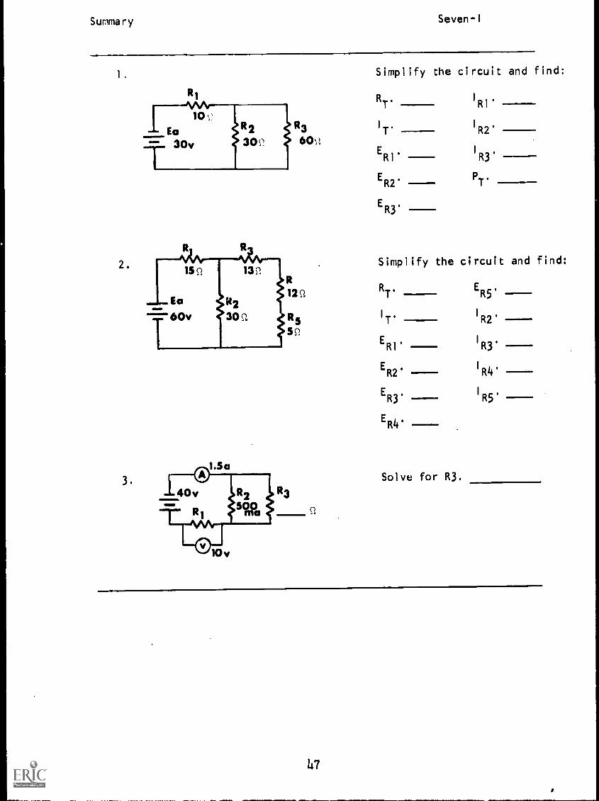
1. Simplify the circuit and find:
RI
2.
3.
R3
6C1).
RT./RI'
IT. I
R2'
ERl. 1113'
ER2. PT'
ER3.
Simplify the circuit and find:
RT. ER5,
IT.I
R2'
ER1' IR3'
ER2.I
R4'
ER3.1115'
ER4'
Solve for R3.
47
Summary
Answers:
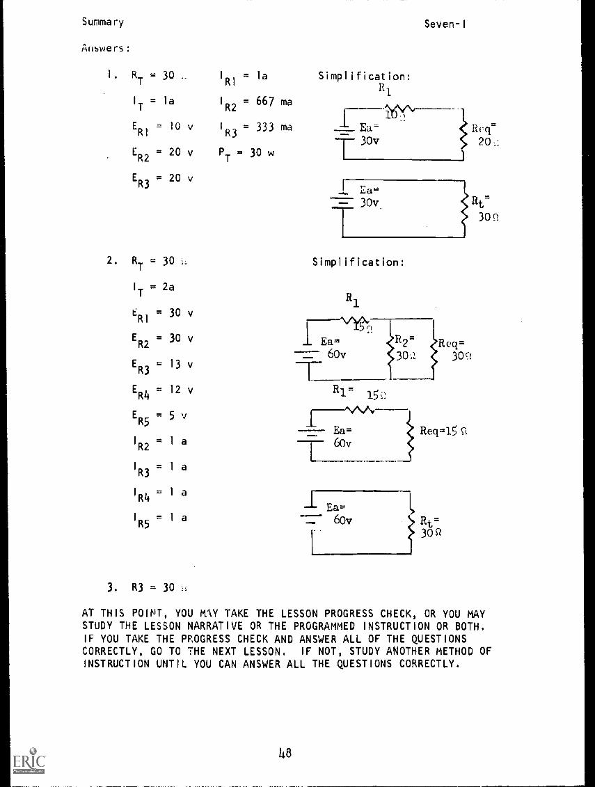
1. RT = 30 I
RI= la
I
T= la I
R2= 667 ma
ER1
= 10 v 1
R3= 333 ma
ER2
= 20 v PT
= 30 w
ER3
= 20 v
2. RT = 30
IT = 2a
ER1 = 30 v
ER2 = 30 v
ER3 = 13 v
ER4 = 12 v
ER5 = 5 v
I
R2= 1 a
I
R3= 1 a
1 R1 a14
R5= 1 a
3 . R3 = 30
Simplification:
Ealad
T 30v
Seven-I
Reg'
20
[ E,a.
30v Rt
Simplification:
R1
N/10,,n
I Ea R2= Re q=
_- 60v 30.z 309,
R1=
Ea=60v
Req=15
_L Ea=-::- 60v Rt=
L30Q
30 P.
AT THIS POINT, YOU MY TAKE THE LESSON PROGRESS CHECK, OR YOU MAYSTUDY THE LESSON NARRATIVE OR THE PROGRAMMED INSTRUCTION OR BOTH.IF YOU TAKE THE PROGRESS CHECK AND ANSWER ALL OF THE QUESTIONSCORRECTLY, GO TO THE NEXT LESSON. IF NOT, STUDY ANOTHER METHOD OFINSTRUCTION UNTIL YOU CAN ANSWER ALL THE QUESTIONS CORRECTLY.
48
NAVPERS 94558-7a
BASIC ELECTRICITY AND ELECTRONICS
INDIVIDUALIZED LEARNING SYSTEM
MODULE SEVENLESSON I I
Voltage Reference
Study Booklet
Bureau of Naval Personnel
January 1972
)49
Overview Seven-II
OVERVI.EW
LESSON II
Voltage Reference
In this lesson you will study and learn about the following:
- why we study voltage reference
- negative and positive voltage
- point of reference
- ground
- ground as common
-polarity of circuit components
- obtaining negative and positive voltages
BEFORE YOU START THIS LESSON, PREVIEW THE LIST OF STUDY RESOURCES ON
THE NEXT PAGE.
50
Study Resources Seven-II
LIST OF STUDY RESOURCES
LESSON II
Voltage Reference
To learn the material in this lesson, you have the option of choosing
according to your experience and preferences, any or all of the following:
STUDY BOOKLET:
Lesson Narrative
Programmed Instruction
Lesson Summary
ENRICHMENT MATERIAL:
NAVPERS 93400A-1a "Basic Electricity, Direct Current."
Fundamentals of Electronics. Bureau of Naval Personnel.
Washington, D.C.: U.S. Government Printing Office, 1965.
YOU MAY NOW STUDY ANY OR ALL OF THE RESOURCES LISTED ABOVE. YOU MAY
TAKE THE PROGRESS CHECK AT ANY TIME.
51
Narrative Seven-II
NARRATIVELESSON 11
Voltage Reference
Why We Study Voltage Reference
In your work in the electrical field, you will discover that somecircuit components such as electronic tubes and transistors requirewhat we call negative voltage to operate them.
Some circuits then, often complex configurations, are designedto supply both positive and negative voltages.
Negative and Positive Voltage
Perhaps now you wonder if a negative voltage has any less zap thana positive voltage. The answer is that 100 volts is 100 volts,whether ;t is negative or positive. The direction of currentflow does not affect the feeling you get when you are shocked.
Point of Reference
A positive voltage means that the point from which we aremeasuring has fewer negative charges (electrons) than the point to
which we are measuring, a negative voltage indicates the reverse;that is, the point from which we are measuring has more negativecharges (electrons) than the point to which we are measuring.
For example, if you place your voltmeter probes across a 12-voltbattery, you get a meter reading of about 12 volts. This means thatthe negative terminal is 12 volts more negative than the positiveterminal, or that the positive terminal is 12 volts more positivethan the negative terminal. The voltage is considered negativeor positive depending on the location of your reference point.
Reading across the battery, we indicate 12 volts positive with re-spect to the negative terminal. Or, we indicate 12 volts negativewith respect to the positive terminal.
In this lesson we will learn how to establish a common referencepoint in a circuit to supply the amount and polarity of voltage re-quired for particular loads.
Ground
To understand how ground can be a common reference point in a cir-cuit, you first need to be familiar with what is meant by ground.
52
Narrative BEST COPY AVAILABLE Seven-II
Frequently, in pieces electrical equipment, the complete path
for electron flow is not supplied by wires. Instead, a wire from
the source may be attached to the metal chassis or case of the equip-
ment as schematically indicated here.
Notice the symbol at point A whichindicates the wire is attached orgrounded to the chassis.--I-- is
one schematic symbol used for ground.
Now the circuit can be groundedto the chassis at point D as shown.At first glance, it may appear as if
the circuit is open between pointsA and D, but this is not so. In
this case the ground symbols indi-cate that the path for current flowis completed by the metal chassis
itself.
Thus current flows through the metalchassis from point A to D andthrough the circuit. A common exam-ple of wiring that is grounded in
this manner is the wiring in yourautomobile.
Let's see how ground relates to other parts of the circuit. If
you were to take a voltmeter reading from grcund (point A) to point B
in this circuit, you would read a 12-B volt difference in potential. Point B
would be 12 volts more positive thanground (point A) because ground (pointA) is connected directly to the negativeterminal of the battery.
In other words, in this schematic at ground, or chassis, we have thesame potential as we have at the negative terminal of the battery.
Similarly, ground at point D is at the same potential as ground at
point A. If you measured voltage from ground (point D) to point C,
you would have a negative 12 volts across the load.
Equipment may be grounded to the chassis at almost any point on thecircuit that the manufacturer chooses.
NOTE: These two symbols -re used interchangeably throughout this lesson
.to represent a reference point. The symbol that looks like a"rake" is most commonly used to show a connection point to chassis.
53
Narrative Seven-II
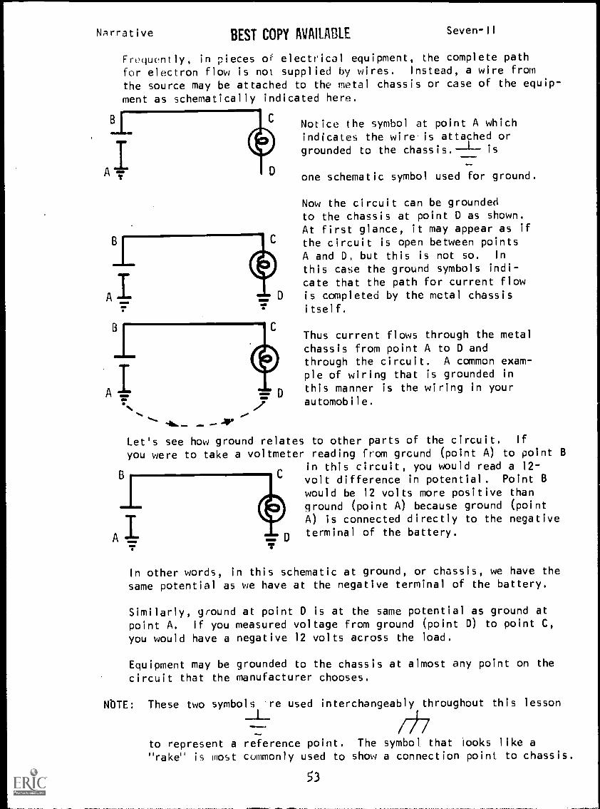
Ground as Common
Ground is not always used to complete the circuit. Sometimes it is
used as a common reference point as shown in the two schematicsbelow.
-L111
Notice that figure (b) shows groundwith a forked symbol like this
This symbol is frequently used torepresent chassis or common refer-ence. All voltages are measuredwith respect to the common point.
(a) (b)
In such cases the chassis or common is almost always considered tobe at zero potent;a1. (If a metal chassis is not at zero potential,we say it is floating.,
If a technician were measuring theoutput voltage of this circuit, hewould clip one voltmeter probe onthe chassis itself, and then movethe other probe to the points hewished to measure with respect to thechassis. With the second probe atpoint A, he would measure a differ-ence in potential of 10 volts.(Observe that the voltage dropsacross RI and R2 would both be 10volts.) Notice that point A is 10
volts positive with respect to thechassis.
Now if the technician moved the probe to point B, he would read a 20-volt difference in potential. With respect to the chassis, point B is
20 volts positive.
Polarity of Circuit Components
Observe in the circuit we have just been measuring that RI and R2 arelabeled according to polarity. You will recall that the end of theload that current enters is designated as negative. The end fromwhich current leaves is designated as positive.
54

Narrative Seven -II
Label the polarity of the resistors in this schematic.
B
R1
20v
R2
10 S2A
10 c
.t..
The polarity signs should be the reverse of what they were in thepreceding schematic because current is flowing in the oppositedirection now.
With respect to chassis, what do you think the voltage and po-larity would be at point A?
at point B?
Point A is 10 volts negative with respect to the common referencebecause ground is now on the positive side of the source, andpoint A is 10 volts less positive than chassis. Point B is 20 voltsnegative with respect to the common reference.
Obtaining Negative and Positive Voltages
Let's see now how we can get both negative and positive voltagesfrom the same circuit.
In the following schematic, what will the voltmeter measureacross RI? Across R2? Across both RI and R2?
11=1=101. 111 111
__L R1
5QR22,5R
b
RI =
R2 =RI + R2 =
Of course RI will be 6 volts and R2 will be 6 volts. Across RI andR2 together the meter will measure 12 volts.
Now take the same circuit and add ground as a reference at pointB, then read voltages.
55
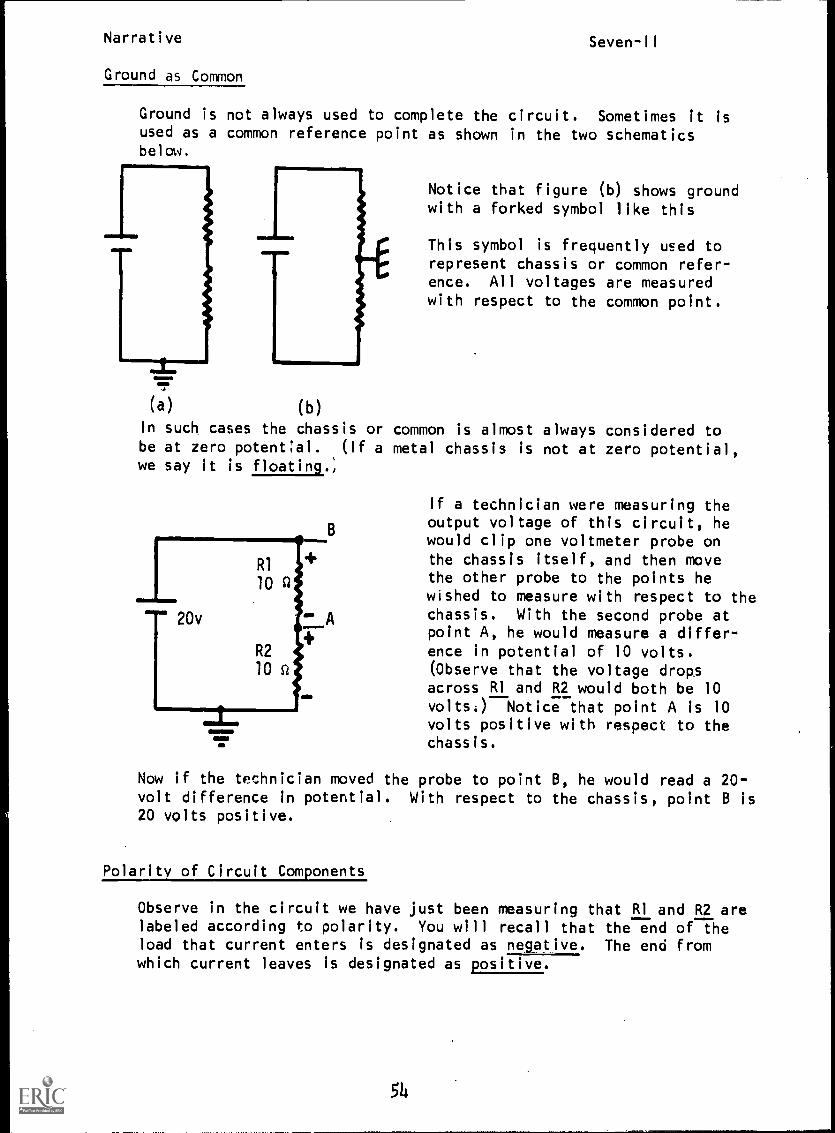
Narrative Seven-II
A
Suppose we place chassis ground atpoint B. With reference to the chassis,we find that point A is 6 volts negativebecause point A is in a more nega-tive position in the circuit thanis the chassis.
Now if we measure from the commonreference to point C, the meter willagain indicate 6 volts. At point C,
however, it is 6 volts positive withrespect to chassis.
You have seen how the same circuit can supply both positive andnegative voltages with respect to a reference point in this
case a -6 volts and a +6 volts.
Always remember, as you measure toward the negative terminal fromthe reference point, your voltage will be negative with respect to
common zero reference. As you are measuring away from the negativeterminal, your voltage will oe positive with respect to common ref-
erence.
Study this schematic, then:1. determine the volta'e drop
10 St
A across each resistor.
2. state the voltage at pointsR1
A, B, and C, and whether theyare negative or positive with
30vR2
10 Q At point A
respect to chassis.
C
R3 At point B
10 sz
At point C
You should have determined from what you have learned about volt-age reference that point A is 20v negative with respect to chassis,
point B is 10v negative, and point C is 10v positive.
In the next lesson you will learn how networks are designed to sup-ply loads that require these positive and negative voltages.
Narrative Seven-II
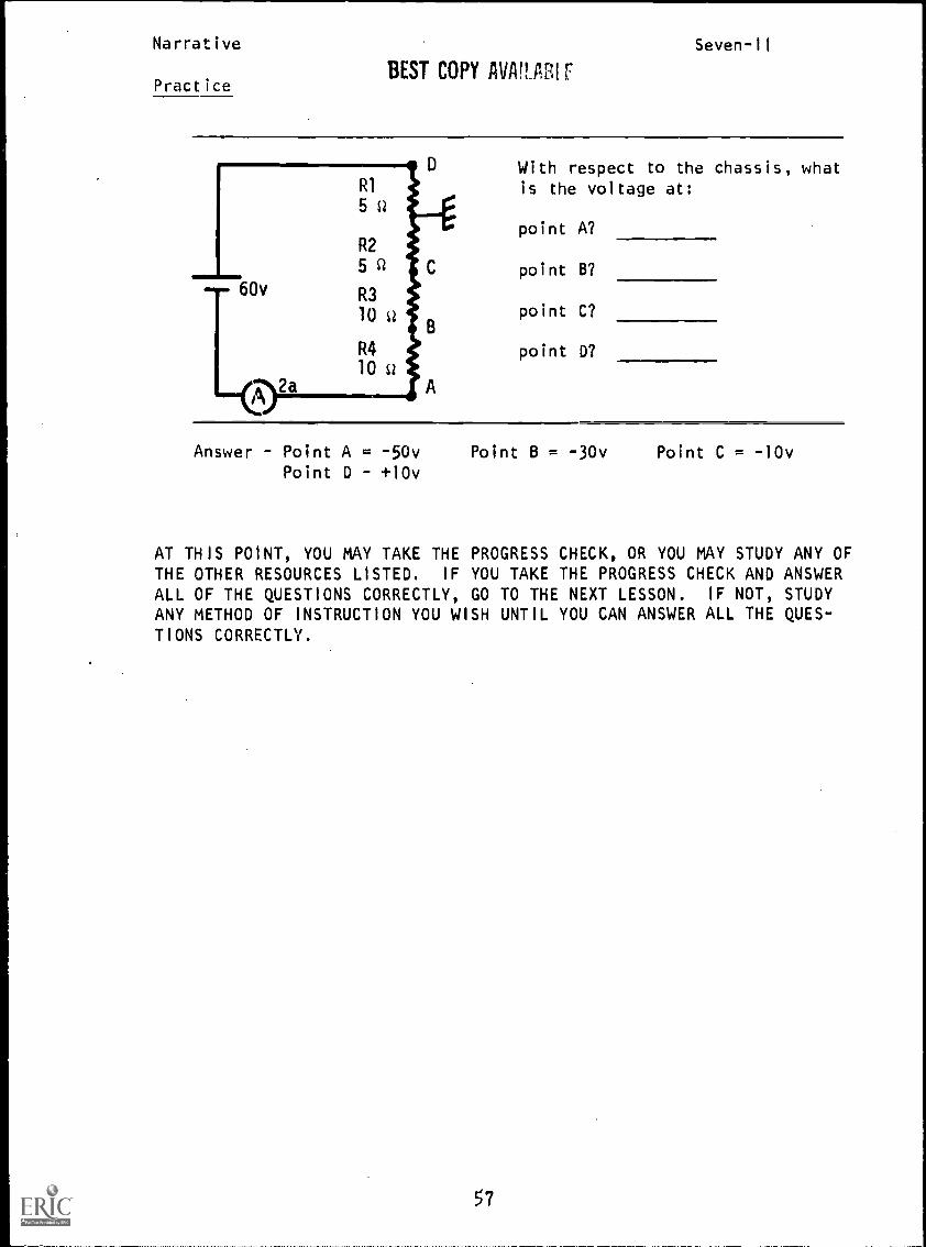
BEST COPY MIMI FPractice
With respect to the chassis, whatis the voltage at:
point A?
point B?
point C?
point D?
Answer Point A = -50vPoint D +10v
Point B = -30v Point C = -10v
AT THIS POINT, YOU MAY TAKE THE PROGRESS CHECK, OR YOU MAY STUDY ANY OFTHE OTHER RESOURCES LISTED. IF YOU TAKE THE PROGRESS CHECK AND ANSWERALL OF THE QUESTIONS CORRECTLY, GO TO THE NEXT LESSON. IF NOT, STUDY
ANY METHOD OF INSTRUCTION YOU WISH UNTIL YOU CAN ANSWER ALL THE QUES-TIONS CORRECTLY.
57
P.I. Seven-II
PROGRAMMED INSTRUCTIONLESSON II
Voltage Reference
THE TEST FRAME IS 24. AS BEFORE, GO FIRST TO TEST FRAME 24 AND SEE IF
YOU CAN ANSWER ALL THE QUESTIONS THERE. FOLLOW THE DIRECTIONS GIVEN
AFTER THE TEST FRAME.
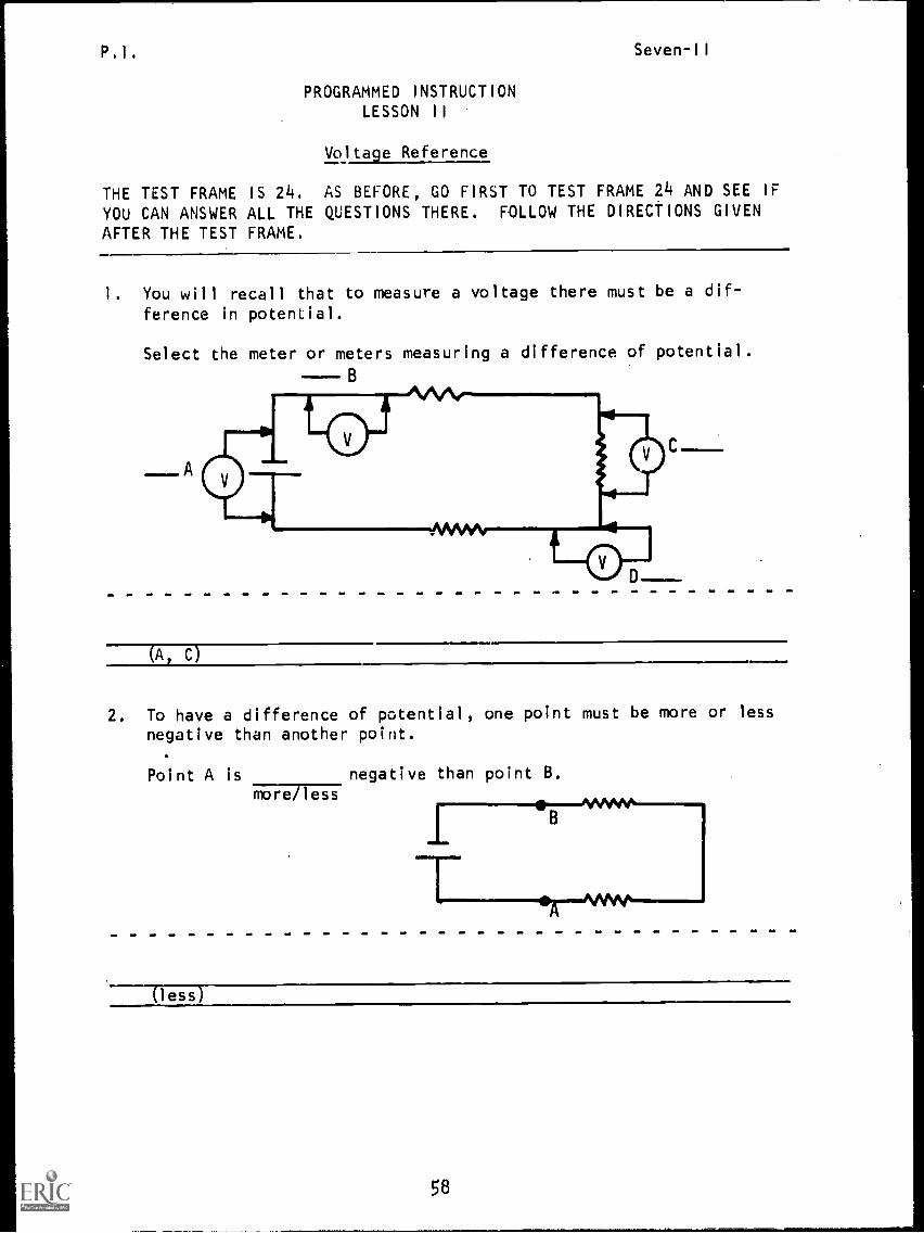
1. You will recall that to measure a voltage there must be a dif-
ference in potential.
Select the meter or meters measuring a difference of potential.
B
(A, c)
2. To have a difference of potential, one point must be more or lessnegative than another point.
Point A is negative than point B.more less
(less)
58
P.,. Seven -II
3. When measuring voltage in a circuit, we measure a point against areference.
The point in a circuit against which other points are comparedis known as a/an
(reference)
4. Most electronic equipment uses the chassis as a common point ofreference.
When measuring voltage in a piece of electronic equipment youuse the as a reference.
(chassis)
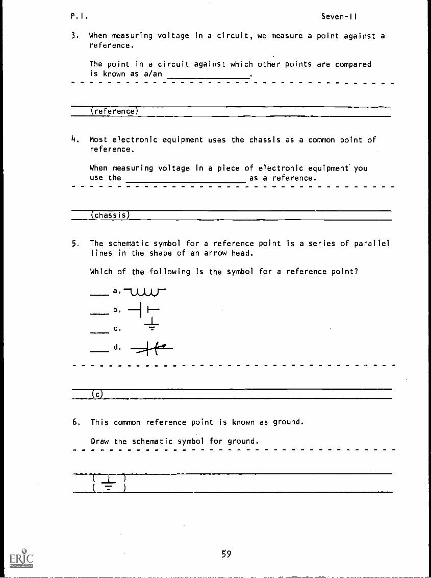
The schematic symbol for a reference point is a series of parallellines in the shape of an arrow head.
Which of the following is the symbol for a reference point?
d.
(c)
6. This common reference point is known as ground.
Draw the schematic symbol for ground.
59
P. I . Seven-II
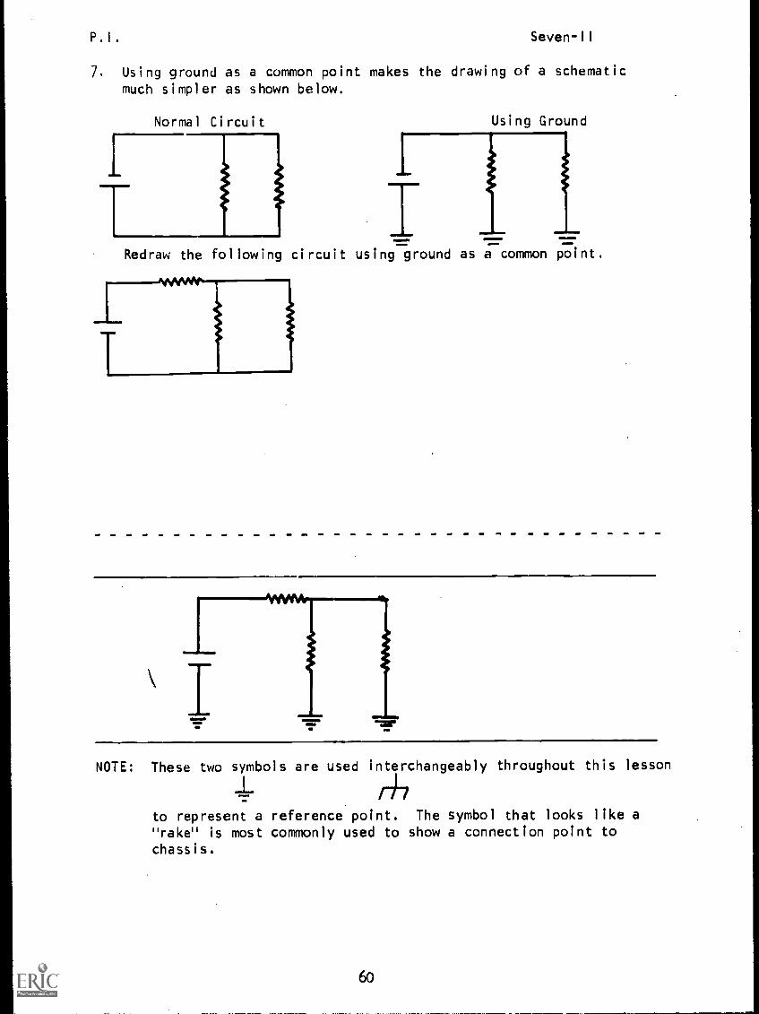
7. Using ground as a common point makes the drawing of a schematicmuch simpler as shown below.
Normal Circuit Using Ground
IRedraw the following circuit using ground as a common point.
NOTE: These two symbols are used interchangeably throughout this lesson
/47to represent a reference point. The symbol that looks like a"rake" is most commonly used to show a connection point tochassis.
60
P. I . Seven-II
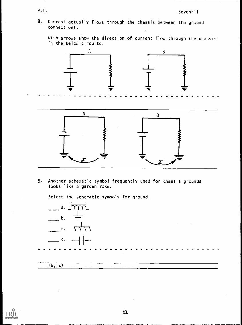
8. Current actually flows through the chassis between the groundconnections.
With arrows show the direction of current flow through the chassisin the below circuits.
A
9. Another schematic symbol frequently used for chassis groundslooks like a garden rake.
Select the schematic symbols for ground,
a.
b.
(b, cr
61
P.I.
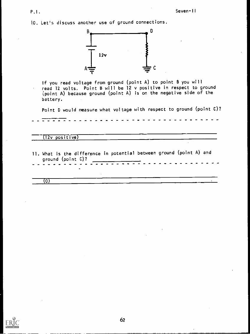
10. Let's discuss another use of ground connections.
_l_ 1
B
III 12v
A r,lr
Seven-II
If you read voltage from ground (point A) to point B you will
read 12 volts. Point B will be 12 v positive in respect to ground(point A) because ground (point A) is on the negative side of the
battery.
Point D would measure what voltage with respect to ground (point C)?
(12v positive)
11. What is the difference in potential between ground (point A) and
ground (point C)?
(0)
62
P.I. Seven-11
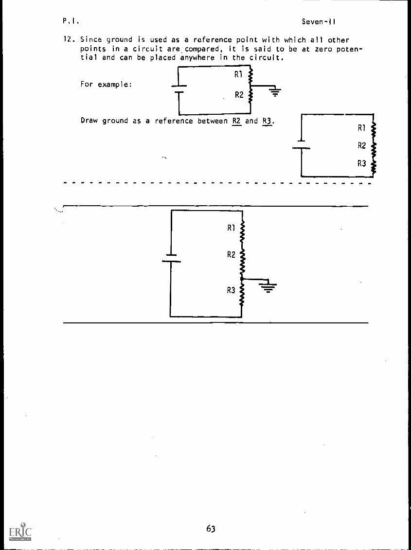
12. Since ground is used as a reference point with which all otherpoints in a circuit are compared, it is said to be at zero poten-tial and can be placed anywhere in the circuit.
For example:
TDraw ground as a reference
R1
R2
between R2 and R3.
1
T
R1
R2
R3
R1
R2
...11==.R3 =111.
all
63
P. I .Seven-11
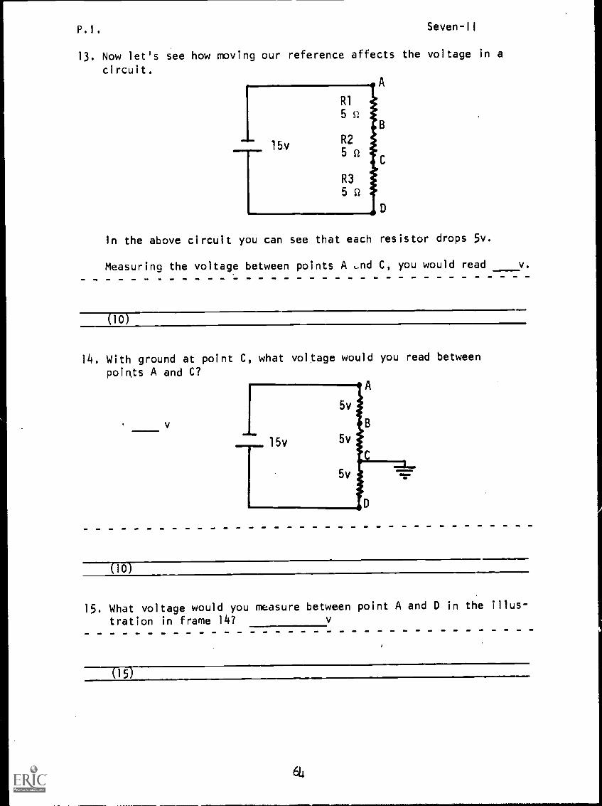
13. Now let's see how moving our reference affects the voltage in a
circuit.A
In the above circuit you can see that each resistor drops 5v.
Measuring the voltage between points A and C, you would read v.
(10)
14. With ground at point C, what voltage would you read betweenpoints A and C?
A
ISMOMINO
(10)
15. What voltage would you measure between point A and D in the illus-
tration in frame 14?
05)
6
P,I. Seven-II
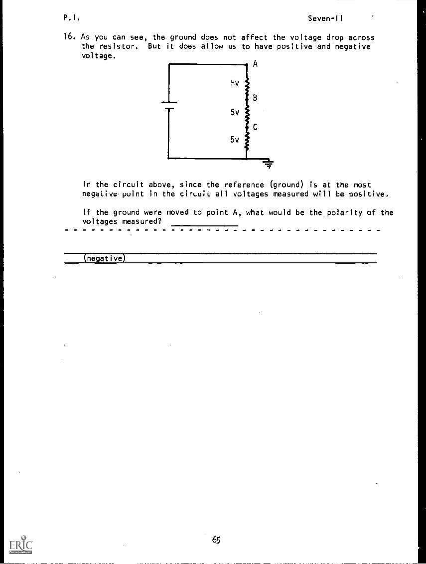
16. As you can see, the ground does not affect the voltage drop acrossthe resistor. But it does allow us to have positive and negativevoltage.
A
Fv
In the circuit above, since the reference (ground) is at the mostnegative point in the cirLuii all voltages measured will be positive.
If the ground were moved to point A, what would be the polarity of thevoltages measured?
(negative)
65
P.I. Seven-II
17. To aid you in understanding what polarity you have at anypoint in a circuit, you must assign polarities to the circuit
component.
(Remember that a negative polarity is assigned to the end of acomponent where current enters, and a positive polarity is as-
signed to the end where current leaves.)
Label the polarity of the components in the following circuit.
;
R1
R2
R1
R2
Note: Even though the lower end
of Rl is marked + and the upperend of R2 is labeled - they areat the same potential.
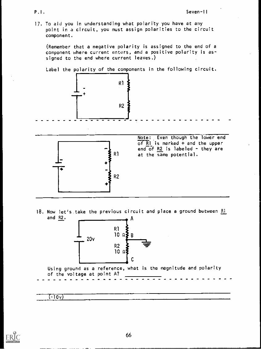
18. Now let's.take the previous circuit and place a ground between Si
and R2. A
R1
10 n20v
R2
10 n
C
Using ground as a reference, what is the magnitude and polarityof the voltage at point A?
(-10v)
66
P.I. Seven-11
19. Rcfcr to the illustration in frame 18. What is the maynitude and
polarity of the voltage at point C?
(+10v)
20. In the illustration in frame 18, what is the voltage between point
A and C?
C200
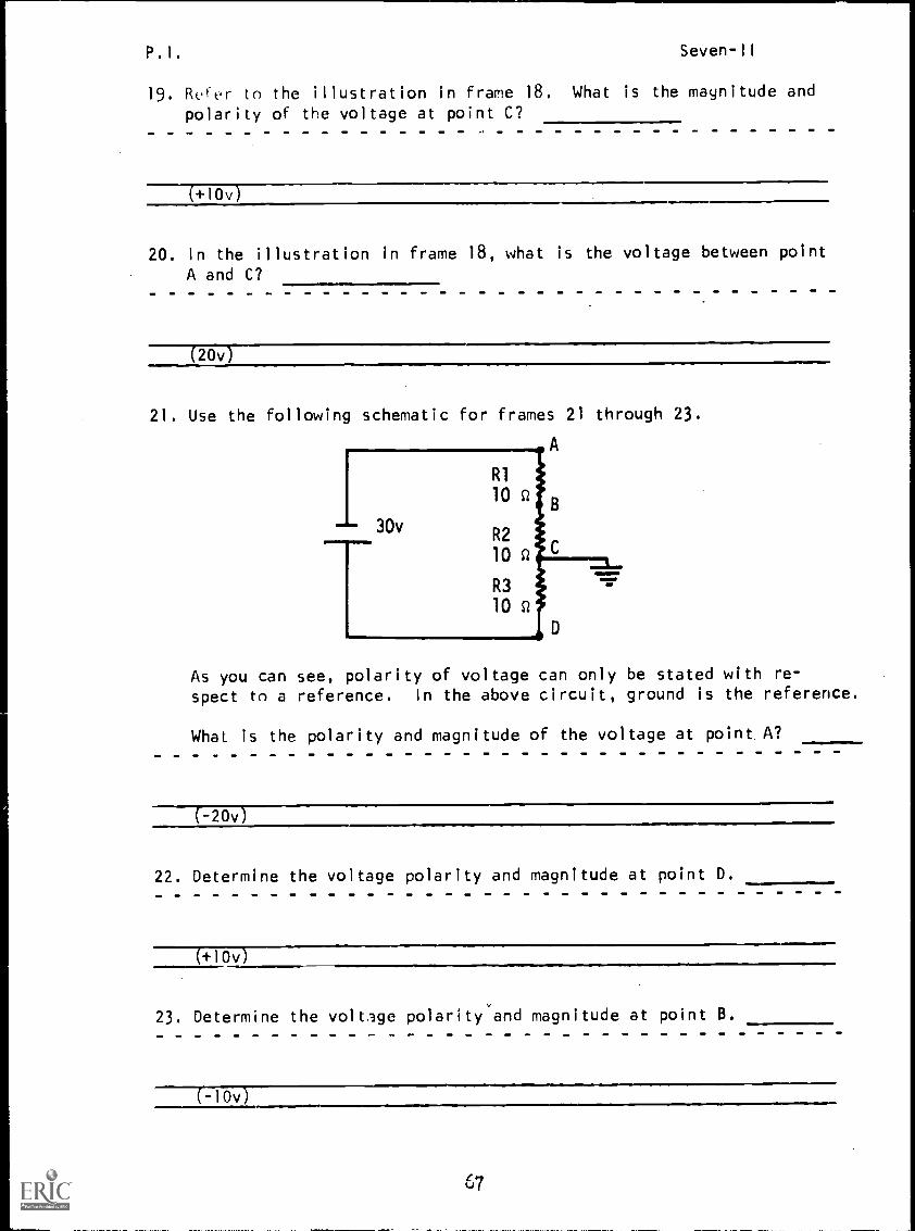
21. Use the following schematic for frames 21 through 23.
A
I 30v
T
R1
10 Q
R2
10 Q
R3
10 SI
IMNIMM
As you can see, polarity of voltage can only be stated with re-spect to a reference. In the above circuit, ground is the reference.
What is the polarity and magnitude of the voltage at point A?
(-20v)
22. Determine the voltage polarity and magnitude at point D.
(+10v)
23. Determine the voltage polarity and magnitude at point B.
-lOv
P.I. Seven-II
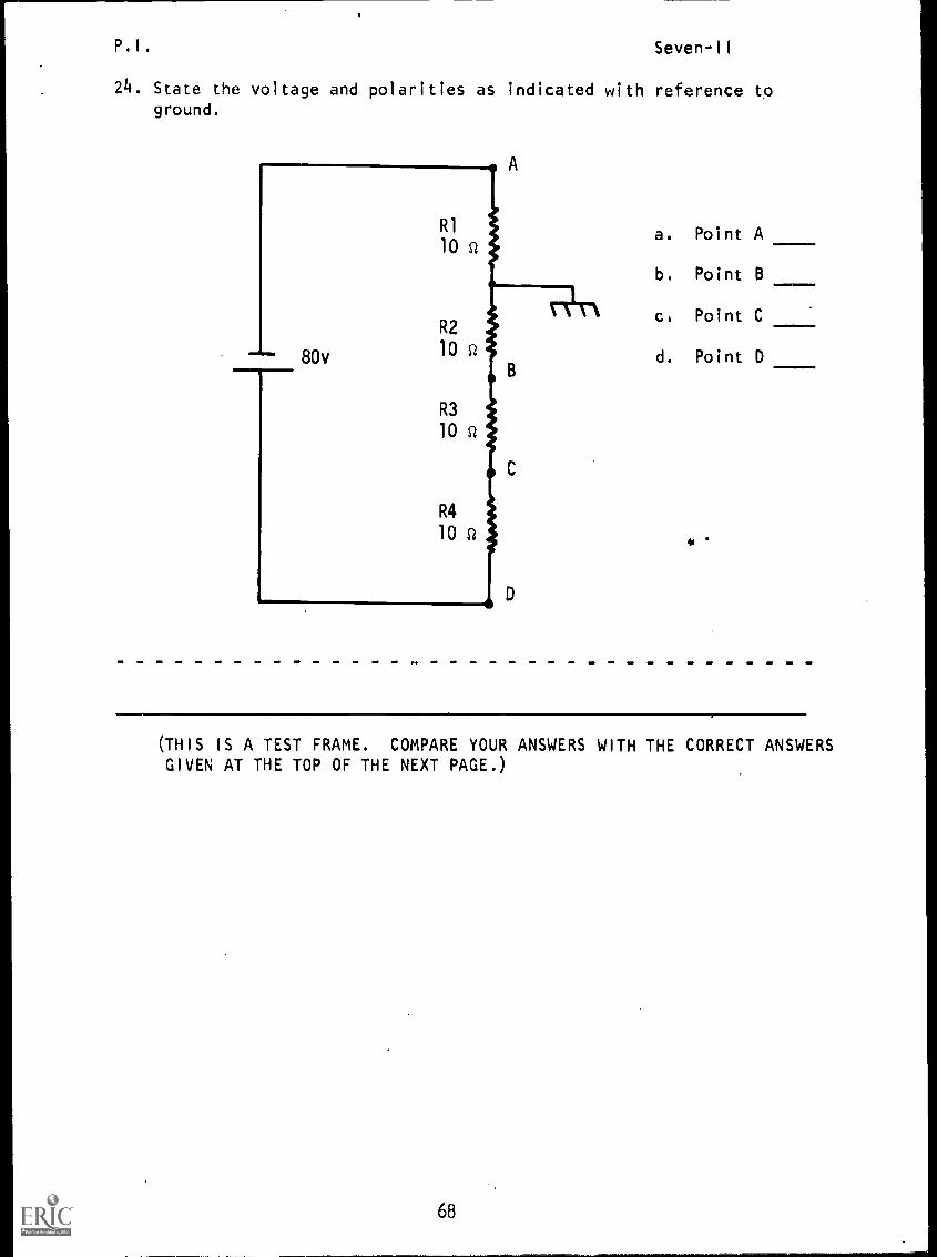
24. State the voltage and polarities as indicated with reference toground.
a. Point A
b. Point B
ce Point C
d. Point D
(THIS IS A TEST FRAME. COMPARE YOUR ANSWERS WITH THE CORRECT ANSWERSGIVEN AT THE TOP OF THE NEXT PAGE.)
68

P.I. Seven-II
ANSWERS TEST FRAME 24
a. -20v
b. +20v
c. +40v
d. +60v
IF ANY OF YOUR ANSWERS IS INCORRECT, GO BACK TO FRAME 1 AND
TAKE THE PROGRAMMED SEQUENCE.
IF YOUR ANSWERS ARE CORRECT, YOU MAY TAKE THE PROGRESS CHECK,
OR YOU MAY STUDY ANY OF THE OTHER RESOURCES LISTED. IF YOU
TAKE THE PROGRESS CHECK AND ANSWER ALL THE QUESTIONS COR-
RECTLY, GO TO THE NEXT LESSON. IF NOT, STUDY ANY METHOD
OF INSTRUCTION YOU WISH UNTIL YOU CAN ANSWER ALL THE QUES-
TIONS CORRECTLY.
69
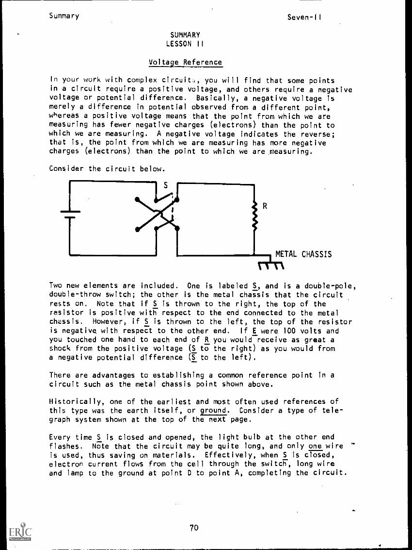
Summary Seven-II
SUMMARYLESSON II
Voltage Reference
In your work with complex circuit.., you will find that some pointsin a circuit require a positive voltage, and others require a negativevoltage or potential difference. Basically, a negative voltage ismerely a difference in potential observed from a different point,whereas a positive voltage means that the point from which we aremeasuring has fewer negative charges (electrons) than the point towhich we are measuring. A negative voltage indicates the reverse;that is, the point from which we are measuring has more negativecharges (electrons) than the point to which we are measuring.
Consider the circuit below.
CHASSIS
Two new elements are included. One is labeled S, and is a double-pole,double-throw switch; the other is the metal chassis that the circuitrests on. Note that if S is thrown to the right, the top of theresistor is positive with respect to the end connected to the metalchassis. However, if S is thrown to the left, the top of the resistoris negative with respect to the other end. If E were 100 volts andyou touched one hand to each end of R you would receive as great ashock from the positive voltage (S to the right) as you would froma negative potential difference (S to the left).
There are advantages to establishing a common reference point in a
circuit such as the metal chassis point shown above.
Historically, one of the earliest and most often used references ofthis type was the earth itself, or ground. Consider a type of tele-graph system shown at the top of the next page.
Every time S is closed and opened, the light bulb at the other endflashes. Note that the circuit may be quite long, and only one wire '
is used, thus saving on materials. Effectively, when S is closed,electron current flows from the cell through the switch, long wireand lamp to the ground at point D to point A, completing the circuit.
70

Summary Seven -II
Low WIRE
GROUND 17; D GROUND
(In actual practice, all that is ,necessary is that electrons flowfrom the earth into the circuit at point A and to the earth from
the circuit at point D.)
As already mentioned above in our double-pole, double-throw switch
experiment, ground itself is not always used to complete the circuit.
Sometimes the metal chassis on which a circuit rests is used as a
reference point, or artificial ground. It can be placed at many
different points as shown in the simple case below.
By definition we usually consider the earth, or the local metal chassis
or common connection point, to be at zero potential. (If a metal chassis
is not at zero potential, we say it is floating.)
The three figures shown above can be used by design technicians by apply-
ing the strategy in reverse. Depending on where the ground is placed,
we can obtain various sources of negative or positive potential.
In the circuit shown at the top.of the next page, where would you place
the common or ground connection to make point A 10 volts negative with
respect to the chassis?
71
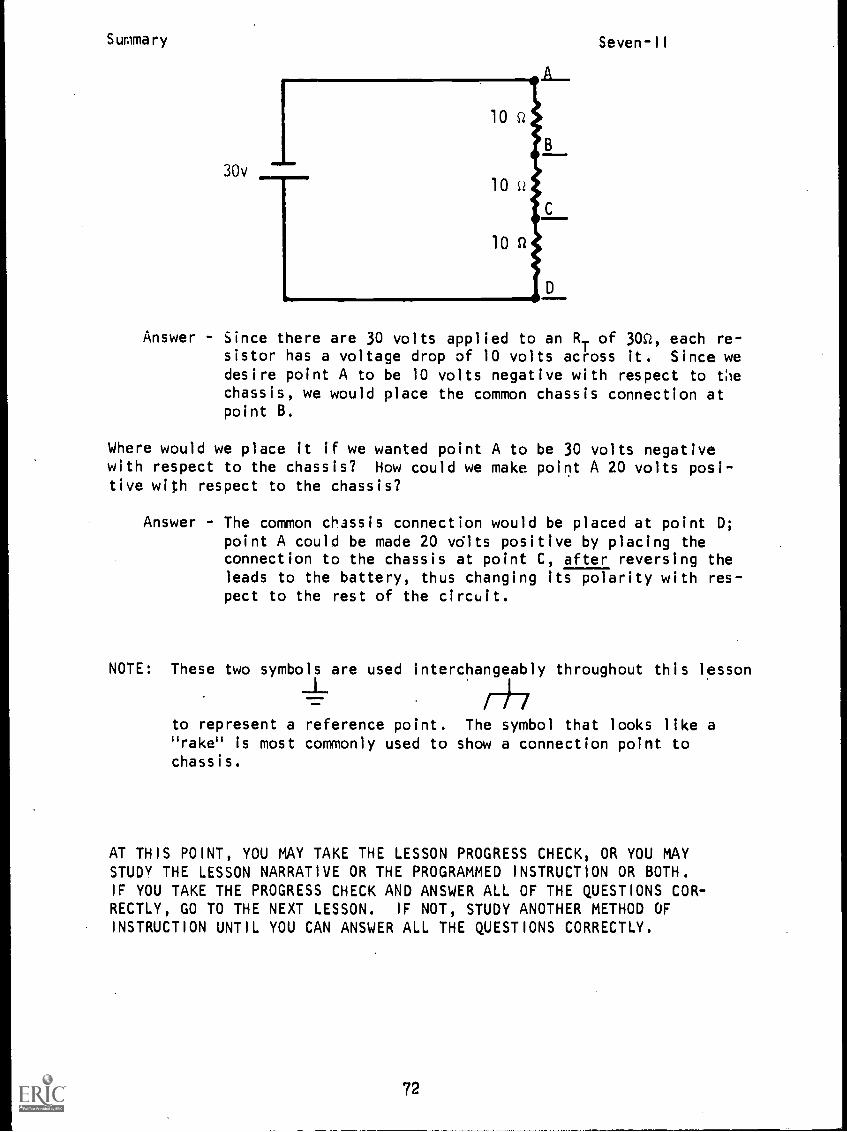
Summary
10 Q
30v10
10 SI
Seven-II
Answer - Since there are 30 volts applied to an RT of 30c, each re-sistor has a voltage drop of 10 volts across it. Since wedesire point A to be 10 volts negative with respect to thechassis, we would place the common chassis connection atpoint B.
Where would we place it if we wanted point A to be 30 volts negativewith respect to the chassis? How could we make point A 20 volts posi-tive with respect to the chassis?
Answer - The common chassis connection would be placed at point D;point A could be made 20 volts positive by placing theconnection to the chassis at point C, after reversing theleads to the battery, thus changing its polarity with res-pect to the rest of the circuit.
NOTE: These two symbols are used interchangeably throughout this lesson
f)-7to represent a reference point. The symbol that looks like arake" is most commonly used to show a connection point to
chassis.
AT THIS POINT, YOU MAY TAKE THE LESSON PROGRESS CHECK, OR YOU MAYSTUDY THE LESSON NARRATIVE OR THE PROGRAMMED INSTRUCTION OR BOTH.IF YOU TAKE THE PROGRESS CHECK AND ANSWER ALL OF THE QUESTIONS COR-RECTLY, GO TO THE NEXT LESSON. IF NOT, STUDY ANOTHER METHOD OFINSTRUCTION UNTIL YOU CAN ANSWER ALL THE QUESTIONS CORRECTLY.
72
NAVPERS 94558-7a
BASIC ELECTRICITY AND ELECTRONICS
INDIVIDUALIZED LEARNING SYSTEM
MODULE SEVENLESSON III
Voltage Dividers
Study Booklet
Bureau of Naval Personnel
January 1972
73
Overview Seven-III
OVERVIEW
LESSON III
Voltage Dividers
In this lesson you will study and learn about the following:
- voltage supply
- no load conditions
- load conditions .
- designing a voltage divider
BEFORE YOU START THIS LESSON, PREVIEW THE LIST OF STUDY RESOURCES ON
THE NEXT PAGE.
714
Study Resources Seven-III
LIST OF STUDY RESOURCES
LESSON III
Voltage Dividers
To learn the material in this lesson, you have the option of choosing,
according to your experience and preferences, any or all of the following:
STUDY BOOKLET:
Lesson Narrative
Programmed Instruction
Lesson Summary
ENRICHMENT MATERIAL:
NAVPERS 93400A-la "Basic Electricity, Direct Current."
Fundamentals of Electronics. Bureau of Naval Personnel.
Washington, D.C.: U.S. Government Printing Office, 1965.
YOU MAY NOW STUDY ANY OR ALL OF THE RESOURCES LISTED ABOVE. YOU MAY
TAKE THE PROGRESS CHECK AT ANY TIME.
75
Narrative Seven-Ill
NARRATIVE
LESSON III
Voltage Dividers
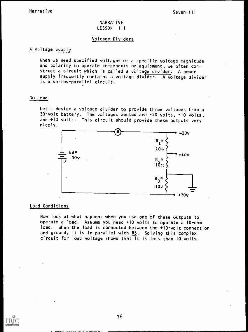
A Voltage Suppjj
When we need specified voltages or a specific voltage magnitudeand polarity to operate components or equipment, we often con-struct a circuit which is called a vbltage divider. A powersupply frequently contains a voltage divider. A voltage divideris a series-parallel circuit.
No Load
Let's design a voltage divider to provide three voltages from a30-volt battery. The voltages wanted are -20 volts, -10 volts,and +10 volts. This circuit should provide these outputs verynicely.
-20v
10vmorilm Es=
30v
R1=
10 ft
18,,2
R3
10L.;
:MOW
+10v
Load Conditions
Now look at what happens when you use one of these uutputs tooperate a load. Assume yoL need +10 volts to operate a 10-ohmload. When the load is connected between the +10-volt connectionand ground, it is in parallel with R3. Solving this complexcircuit for load voltage shows that it is less than 10 volts.
76
Narrative Seven-III
Find: Req
of R3 and load
IT
ELOAD
Req
is 5'
I
T '
= 1.2 a; ELOAD
= 6 v
You can now see that designing a voltage divider without consideringthe load resistance (or current) does not work.
Designing a Voltage Divider
Assume we begin by knowing only that we have a series circuit with
three resistors and an applied voltage of 24 volts. We want to
furnish voltage to two lamps, a 12-volt lamp and a 6-volt lamp.The 12-volt lamp will draw 8 milliamps of current; the 6-volt
lamp, 2 milliamps.
We need to find what value of resistors will do the job.
OM.
Ds-1
6v
We plan to add the 6-volt lamp across R3because it requires less voltage than
the 12-volt lamp.
Note: The schematic shows the new branchrunning to chassis (grounded to the chas-sis) where current makes a complete paththrough the metal case. It could also be
drawn with a line indicating connectingwires.
Now we add the 12-volt lamp across R2and R3 as shown. It is also grounded to
the chassis.
D6 -2 The6-volt lamp draws 2 milliamps, so we
12v can write that on the horizontal line as
shown. The 8 milliamps that the 12-voltlamp draws is written on the proper line.
77
Narrative Seven-III
Notice that we now have a voltage divider consisting of RI, R2,and R3. The lamps, DS1 and DS2, are the load resistances. One ofthe divider resistors has none of the load current flowing throughit. This resistor is designated the bleeder resistor.
R
24v
bleeder
resistor
8ma
DS-2
DS-1 12v6v
In this network, R3 is the bleederresistor.
There are three steps to follow in order to design this voltagedivider network once the load voltages and currents have beendetermined.
Step One: Determine Bleeder Current.
24v
bleeder
resister
Sma
2ma
R3
DS-2
12v
Current drawn by the bleeder resistor is usually 10% (1/10) of thevalue of the sums of the load currents.
IDS1
+ I
DS2x 10% = I
R3
8ma + 2ma x 10% = lma
Also, we know that the bleeder resistor, R3 is in parallel withthe 6 volt load. If we need 6 volts across the load, then, E
P3must be 6 volts.
Using Ohm's Law, determine the resistance value of the bleederresistor.
R3
=
Bleeder resistor is determined to be 6 kilohms.
78
Narrative Seven-di!
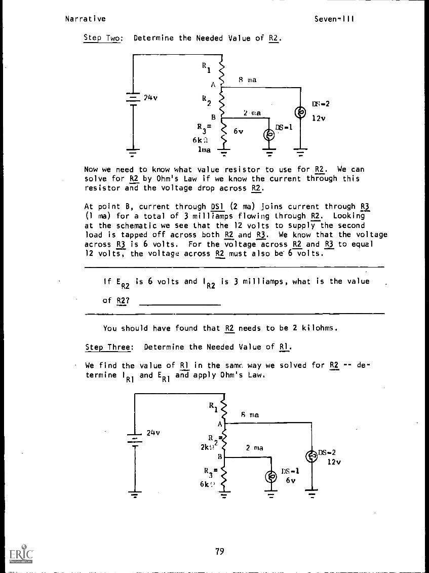
Step Two: Determine the Needed Value of R2.
DS-2
12v
Now we need to know what value resistor to use for R2. We cansolve for R2 by Ohm's Law if we know the current through thisresistor and the voltage drop across R2.
At point B, current through DS1 (2 ma) joins current through R3(1 ma) for a total of 3 milliamps flowing through R2. Looking
at the schematic we see that the 12 volts to supply the secondload is tapped off across both R2 and R3. We know that the voltageacross R3 is 6 volts. For the voltage across R2 and R3 to equal12 volts, the voltage across R2 must also be 6 volts.
If ER2
is 6 volts and I
R2is 3 milliamps, what is the value
of R2?
You should have found that R2 needs to be 2 kilohms.
Step Three: Determine the Needed Value of RI.
We find the value of RI in the saw. way we solved for R2 -- de-termine I
Illand E
R1and apply Ohm's Law.
124v
4111,11Mb
8 maA
R
210.2
13
R3
6k
2 ma
79
DS -
6v111 11
DS-212v
Narrative Seven-Ili
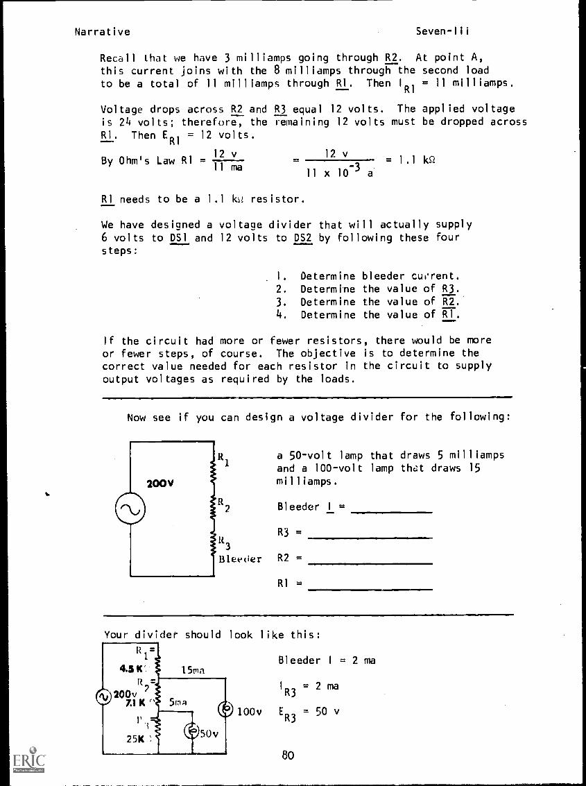
Recall that we have 3 milliamps going through R2. At point A,
this current joins with the 8 milliamps through the second loadto be a total of 11 milliamps through RI. Then IRI = 11 milliamps.
Voltage drops across R2 and R3 equal 12 volts. The applied voltageis 24 volts; therefore, the remaining 12 volts must be dropped acrossRI. Then E
R1= 12 volts.
By Ohm's Law RI =12 v
11 ma
RI needs to be a 1.1 kst resistor.
12 v
11 x 10-3 a
= 1 . 1 Id2
We have designed a voltage divider that will actually supply6 volts to DS1 and 12 volts to DS2 by following these foursteps:
1. Determine bleeder cuvrent.
2. Determine the value of R3.
3. Determine the value of R2.4. Determine the value of RI.
If the circuit had more or fewer resistors, there would be moreor fewer steps, of course. The objective is to determine thecorrect value needed for each resistor in the circuit to supplyoutput voltages as required by the loads.
Now see if you can design a voltage divider for the following:
lt
3
Bleeder R2 =
a 50-volt lamp that draws 5 milliampsand a 100-volt lamp that draws 15milliamps.
Bleeder I =
R3 =
RI =
Your divider should look like this:
Bleeder I = 2 ma
1
R3= 2 ma
100v ER3
= 50 v
80
Narrative
or this:
00v
1 R2= 7 ma
ER2 = 50 v
R2 = 7 k,.
ER1
= 100 v
IRi = 22 ma
RI = 4.5 106
Seven-111
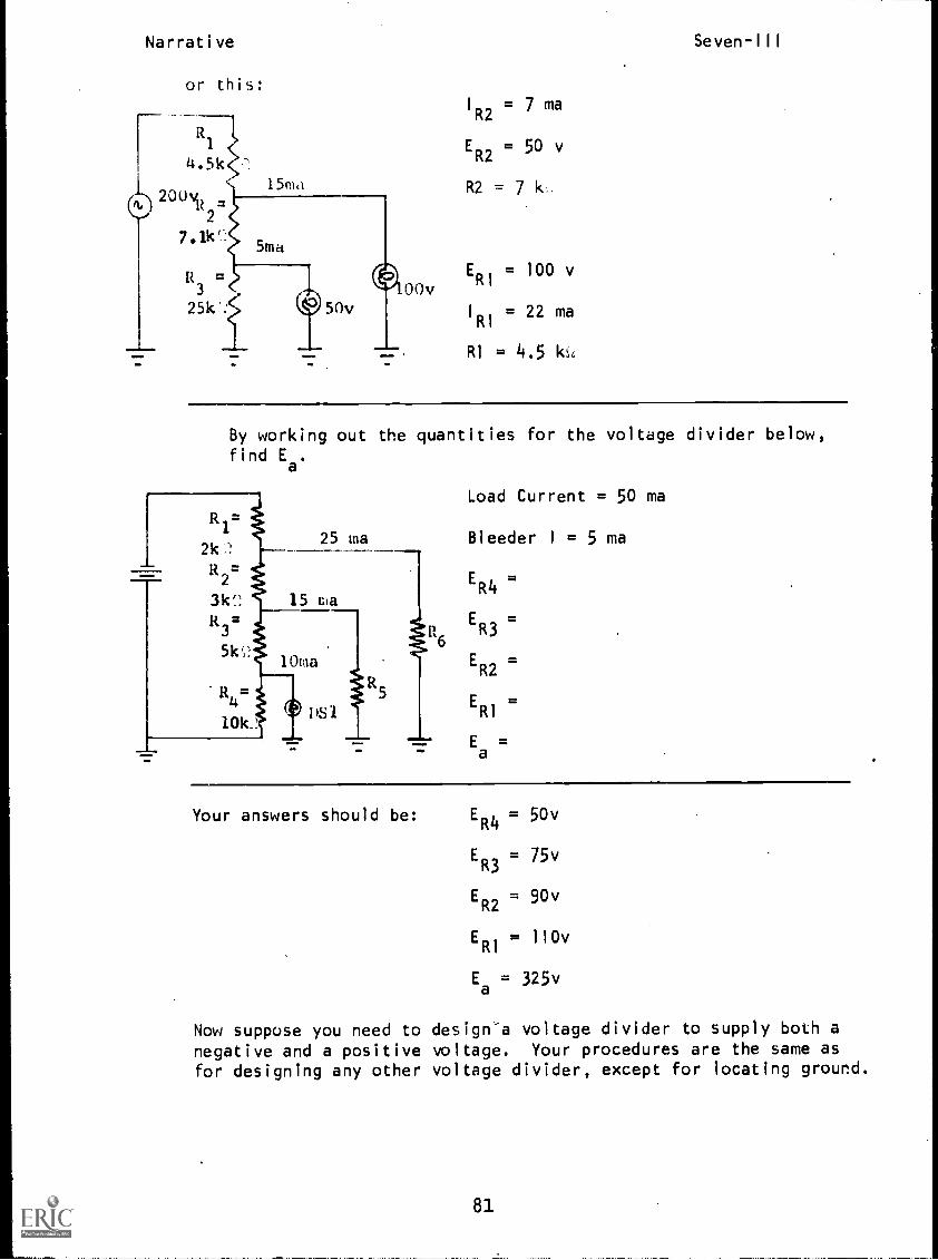
By working out the quantities for the voltage divider below,find E
a.
R1=
21C!
R2=
31c?: 15 ma
R3
51c,10ma
25 ma
R4
101c161
Load Current = 50 ma
Bleeder I = 5 ma
ER4
=
R6
ER3
=
ER2
=
ERI
=
Ea
=411=IMI
Your answers should be: ER4
= 50v
ER3
= 75v
ER2
= 90v
ERI
= 110v
Ea= 325v
Now suppose you need to design-a voltage divider to supply both anegative and a positive voltage. Your procedures are the same asfor designing any other voltage divider, except for locating ground.
81
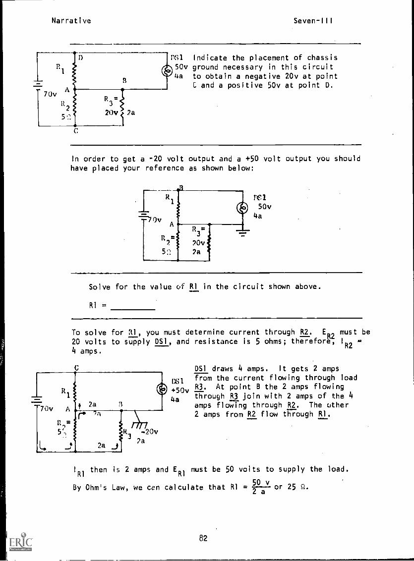
Narrative Seven-III
PS1 Indicate the placement of chassis50v ground necessary in this circuit4a to obtain a negative 20v at point
C and a positive 50v at point O.
In order to get a -20 volt output and a +50 volt output you shouldhave placed your reference as shown below:
DEll
50v4a
Solve for the value of RI in the circuit shown above._,....
RI =
To solve for RI, you must determine current through R2. E02 must be
20 volts to supply OS1, and resistance is 5 ohms; therefore, 1R24 amps.
DS1 draws 4 amps. It gets 2 amps
assfrom the current flowing through load
+50v R3. At point B the 2 amps flowing
4a through R3 join with 2 amps of the 4amps flowing through R2. The other2 amps from R2 flow through RI.
I
RIthen is 2 amps and E
RImust be 50 volts to supply the load.
0
a
vBy Ohm's Law, we can calculate that RI =
5or 25 Q.
2
82
Narrative Seven-III
Problem
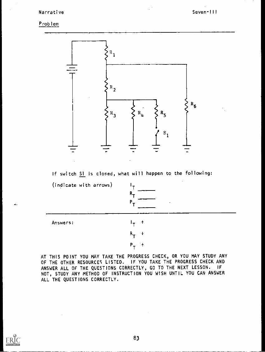
1111=www
R2
R3 R4
R5
I sl
1111
If switch Si is closed, what will happen to the following:
(indicate with arrows) I
T
RT
PT
Answers: I
Tt
RT
PT
t
AT THIS POINT YOU MAY TAKE THE PROGRESS CHECK, OR YOU MAY STUDY ANYOF THE OTHER RESOURCES LISTED. IF YOU TAKE THE PROGRESS CHECK AND
ANSWER ALL OF THE QUESTIONS CORRECTLY, GO TO THE NEXT LESSON. IF
NOT, STUDY ANY METHOD OF INSTRUCTION YOU WISH UNTIL YOU CAN ANSWERALL THE QUESTIONS CORRECTLY.
83

P.I. Seven-III
PROGRAMMED INSTRUCTIONLESSON III
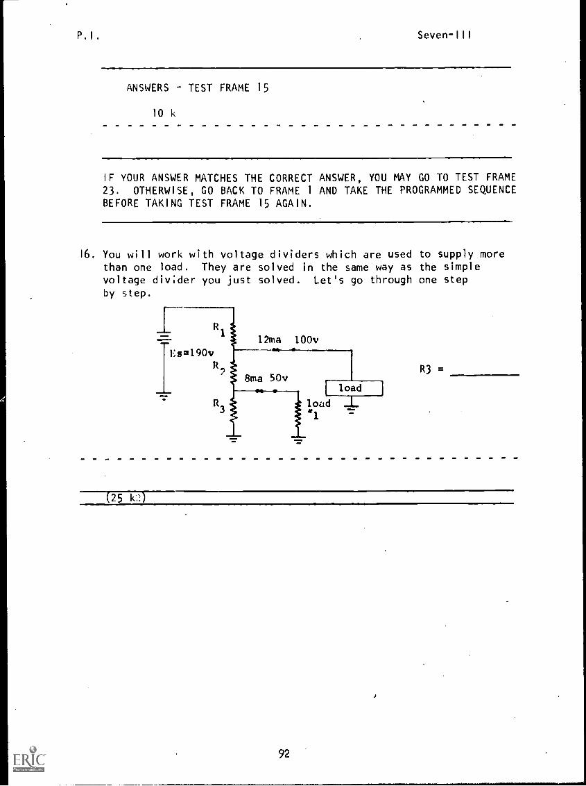
Voltage Dividers
TEST FRAMES ARE 15, 23 AND 28. AS BEFORE, GO FIRST TO TEST FRAME 15 ANDSEE IF YOU CAN ANSWER ALL THE QUESTIONS THERE. FOLLOW THE DIRECTIONSGIVEN AFTER THE TEST FRAME.
1. Recall that different polarities of voltage can be obtained byvarying the common reference in the circuit.
The common reference point in a circuit is called aand its symbol is
_L )
(ground; 1'7 )
2. As you have already learned, a series circuit can provide variousvoltages depending upon where the voltage is taken from.
How many voltages could be provided by the following circuit?Assume ground is always part of the load cjrcuit.
MillIMA
M11
60v
= 5(
13
R2= 10 CZ
R3= 45 c2
(three)
84
P.I. Seven-III
3. Refer to the above diagram. What is the voltage magnitude and polar-
ity.at points A, B, and C with no loads connected?
A.
B.
C.
(A. +60v; B. +55v; C. +45v)
4. As you can see, various magnitudes and polarities of voltage can besupplied by a simple series circuit. This is the purpose of a
voltage divider.
State the purpose of a voltage divider (in your own words).
(To supply various polarities and magnitudes of voltages.)
5. In its simplest form, a voltage divider consists of a simple
series-parallel circuit. The parallel portion contains the load
(DS1) being supplied.
Circle the load in the following:
DS1
DS1
85
P.I. Seven-III
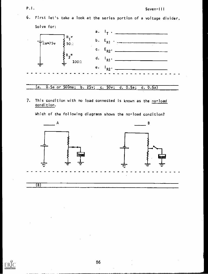
6. First let's take a look at the series portion of a voltage divider.
Solve for:
--Es=75v
R2=
1009.
a. I
T
b. ER1
c. ER2
.
d. I
RI*
e. I
R2'
(a. 0.5a or 500ma; b. 25v; c. 50v; d. 0.5a; d. 0.5a)
7. This condition with no load connected is known as the no-loadcondition.
Which of the following diagrams shows the no-load condition?
A
(B)
86
P.I. Seven-III
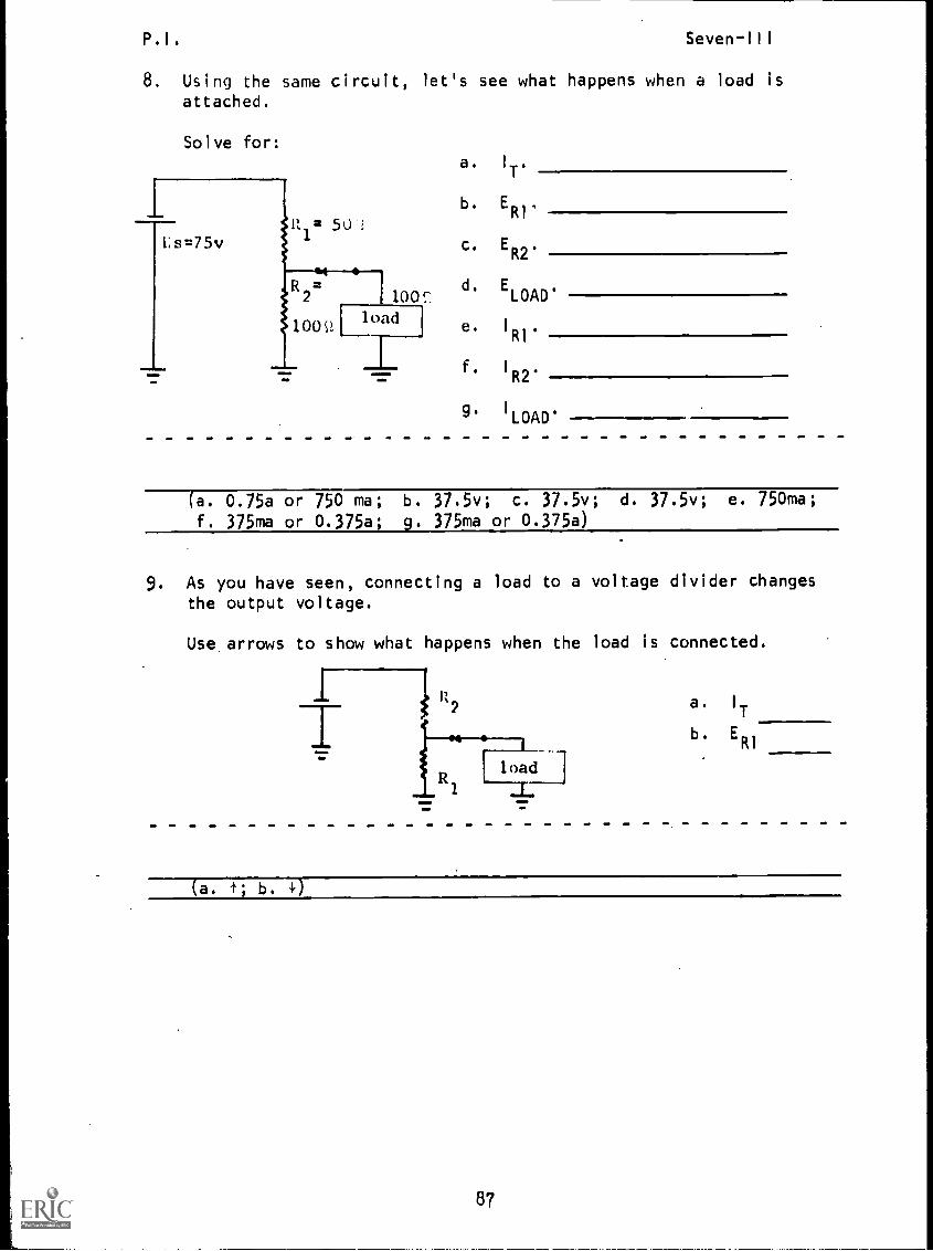
8. Using the same circuit, let's see what happens when a load isattached.
Solve for:
Ls=75v
-1-
R =50'2
R2=
1001
- Iload
a. IT'
b. ER1.
c. E.
d. ELOAD'
e. I
R1'
f. I
R2'
g. I
LOAD'
(a. 0.75a or 750 ma; b. 37.5v; c. 37.5v; d. 37.5v; e. 750ma;
f. 375ma or 0.375a; g. 375ma or 0.375a)
9. As you have seen, connecting a load to a voltage divider changesthe output voltage.
Use, arrows to show what happens when the load is connected.
R2a. I
T
«4 b. ER1
load
1
(a. +; b. 4)
87

P.I. Seven-111
10. The resistor R2 in the below circuit is known as the bleederresistor.
Circle the bleeder resistor.
11. The bleeder resistor is a resistor in the voltage divider networkthrough which none r)f the load current flows.
Solve for the current flowing through the bleeder resistor under
no-load condition.
R1
12Es=24v
91
R2 =R7=
12Ct
NO
1
(1 amp)
88

P.I. Seven-III
12. We have discovered that the voltage available at a given point un-der no-load conditions is not the same as the voltage at the same
point when a load is attached. (Note: This is true only whenthere is a. resistor through which the load current will flow be-tween the point where the load is attached and the source.) It
becomes apparent then that a voltage divider must be designed to
supply a given load.
Let's see how this is done by designing a voltage divider to sup-
ply a load drawing 10 ma requiring a voltage of 24 v.
First the current through bleeder resistor R2 is determined byknowing that IR2 usually is 10% of the value of the sum of the
load currents.
Second, find the resistance value of bleeder resistor R2.
nllUma 24v Find IR2.
R Find IT.
D61Find R2.
(IT
= 11 ma) First, 10% of 10 ma = 1 ma. Next came the need to
use your knowledge that current in parallel branches join and are
added to become total current.
I
T= I
R2+ load current
I
T= 1 ma + 10 ma = 11 ma
(R2
= 24 Ks') You had to do a little thinking here. You had to.first remember that the branch voltages in a parallel network are
the same. Then you had to use Ohm's Law to find R2.
24vR =2 1 ma
R2
= 241C
89
P.I. Seven-Ill
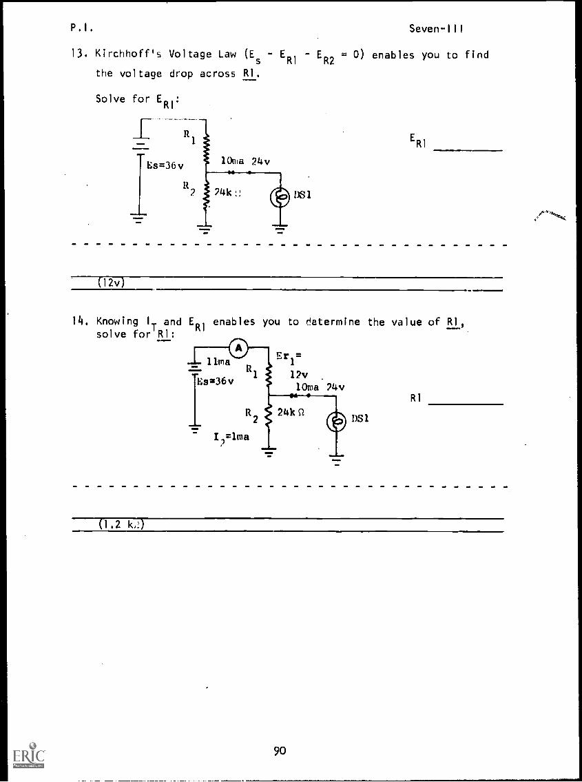
13. Kirchhoff's Voltage Law (Es
- ERI
- ER2
= 0) enables you to find
the voltage drop across RI.
Solve for ERI
:
Es=361.,
=1111.MEM.
DS 1
ERI
0 2 v)
14. Knowing I.. and ER1 enables you to determine the value of RI,solve for RI:
1)31
RI
0.2 ic!)
90
P.I. Seven-Ill
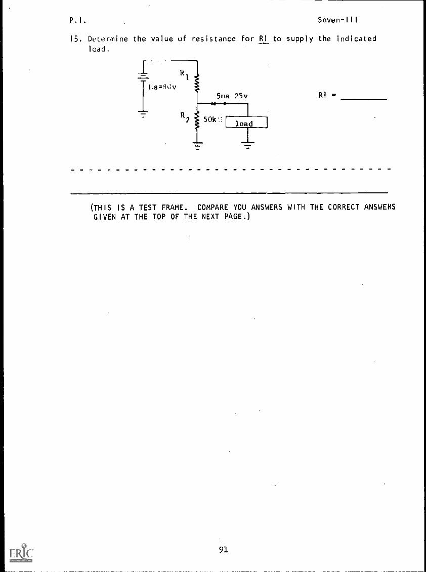
15. Determine the value of resistance for RI to supply the indicated
load.
RI =
(THIS IS A TEST FRAME. COMPARE YOU ANSWERS WITH THE CORRECT ANSWERSGIVEN AT THE TOP OF THE NEXT PAGE.)
91
P.I. Seven-Ill
ANSWERS TEST FRAME 15
10 k
IF YOUR ANSWER MATCHES THE CORRECT ANSWER, YOU MAY GO TO TEST FRAME23. OTHERWISE, GO BACK TO FRAME 1 AND TAKE THE PROGRAMMED SEQUENCEBEFORE TAKING TEST FRAME 15 AGAIN.
16. You will work with voltage dividers which are used to supply morethan one load. They are solved in the same way as the simplevoltage divider you just solved. Let's go through one stepby step.
R3
(25 k7.)
92
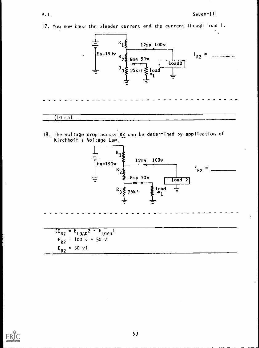
P.I. Seven-III
17. You now know the bleeder current and the current though load I.
I R2=
(10 ma)
18. The voltage drop across R2 can be determined by application ofKirchhoff's Voltage Law.
-1- R---
I1
Es=190v2ma 100v
R
.... Sma 50v r load 21
25kQ
.* i
load 1.'1
.1=t=0
ER2=
(ER2
= ELOAD
2 - ELOAD
1
ER2
= 100 v 50 v
ER2
= 50 v)
93
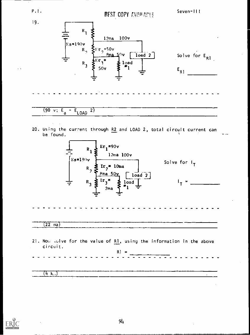
P.I. Seven-IIIREST COPY OinliMcz
19.
Es=190vR,
12ma 100v
v [load 21
5
load
0v 1
Solve for ERI
ERI
90 v; Ea
ELOAD
2
20. Using the current through R2 and LOAD 2, total circuit current canbe found.
R290v
12ma 100vEs219nv
Ir2x 10ma :1
Rma 50v
Tr3=
2ma
load 2
load ±.1
Solve for I..
122 ma-)
21. No,,, ,calve for the value of RI, using the information in the abovecircuit.
RI =
(4
94
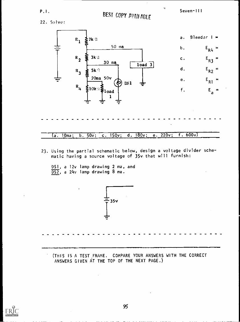
P.I.
22. Solve:
BEST COPY /Willi /IRE
20ma 50v
10k1load
1aM=NO
DS1
load 41
Seven-III
a. Bleeder I =
b.
c.
d.
e.
f.
ER4
=
ER3
=
ER2
=
ER1
=
Ea
(a. 10ma; b. 50v; c. 150v; d. 180v; e. 220v; f. 600v)
23. Using the partial schematic below, design a voltage divider sche-matic having a source voltage of 35v that will furnish:
DS1, a 12v lamp drawing 2 ma, andDS2, a 24v lamp drawing 8 ma.
T35v
(THIS IS A TEST FRAME. COMPARE YOUR ANSWERS WITH THE CORRECTANSWERS GIVEN AT THE TOP OF THE NEXT PAGE.)
95
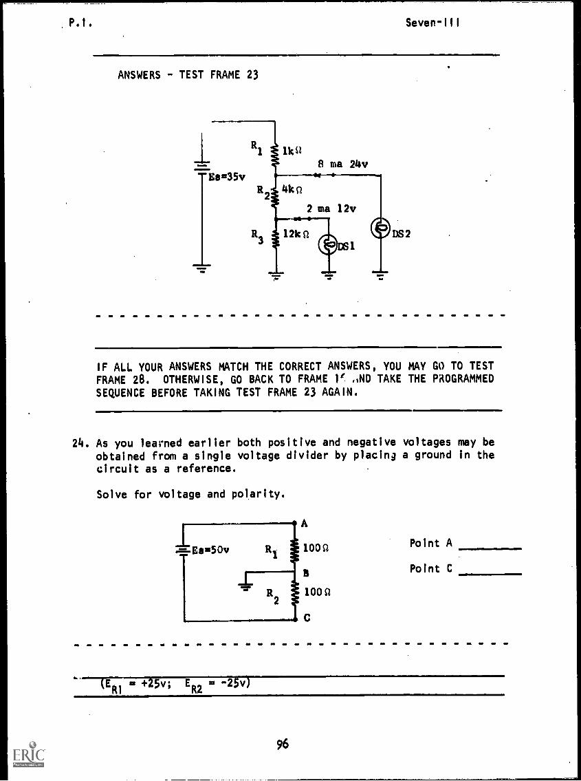
P.I.
ANSWERS - TEST FRAME 23
IF ALL YOUR ANSWERS MATCH THE CORRECT ANSWERS, YOU MAY GO TO TEST
FRAME 28. OTHERWISE, GO BACK TO FRAME 1' AND TAKE THE PROGRAMMEDSEQUENCE BEFORE TAKING TEST FRAME 23 AGAIN.
24. As you learned earlier both positive and negative voltages may beobtained from a single voltage divider by placing a ground in thecircuit as a reference.
Solve for voltage and polarity.
= +25v; ER2 = -2g-0
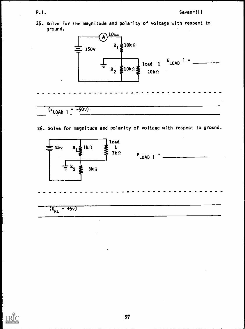
P .1 . Seven-ill
25. Solve for the magnitude and polarity of voltage with respect toground.
10m
150v10k Si
=load 1
ELOAD 1
10k10k St
=LOAD 1
-50v
26. Solve for magnitude and polarity of voltage with respect to ground.
load
1
lk Si ELOAD 1
cc:= +5v)
97

P.I. Seven-IIIBEST COPY AVAILABLE
27. Using the methods learned, solve the following for magnitude andpolarity with respect to ground:
=- 300vR 400 Q
load 2
133Q ELOAD 1 =
-.100Q
ELOAD 2 =
load.=
la1
100Q
(ERL1
= -100v.'
ERL2
= +200v)
28. In the schematic below, determine the value of R1 and indicate theplacement of ground required to supply the loads as indicated.
-50v load (2 amps), and+100v load (3 amps)
load 1
+100v3a
load 2
-50v2a
R1 mg
(THIS IS A TEST FRAME. COMPARE YOU ANSWERS WITH THE CORRECTANSWERS GIVEN AT THE TOP OF THE NEXT PAGE.)
98
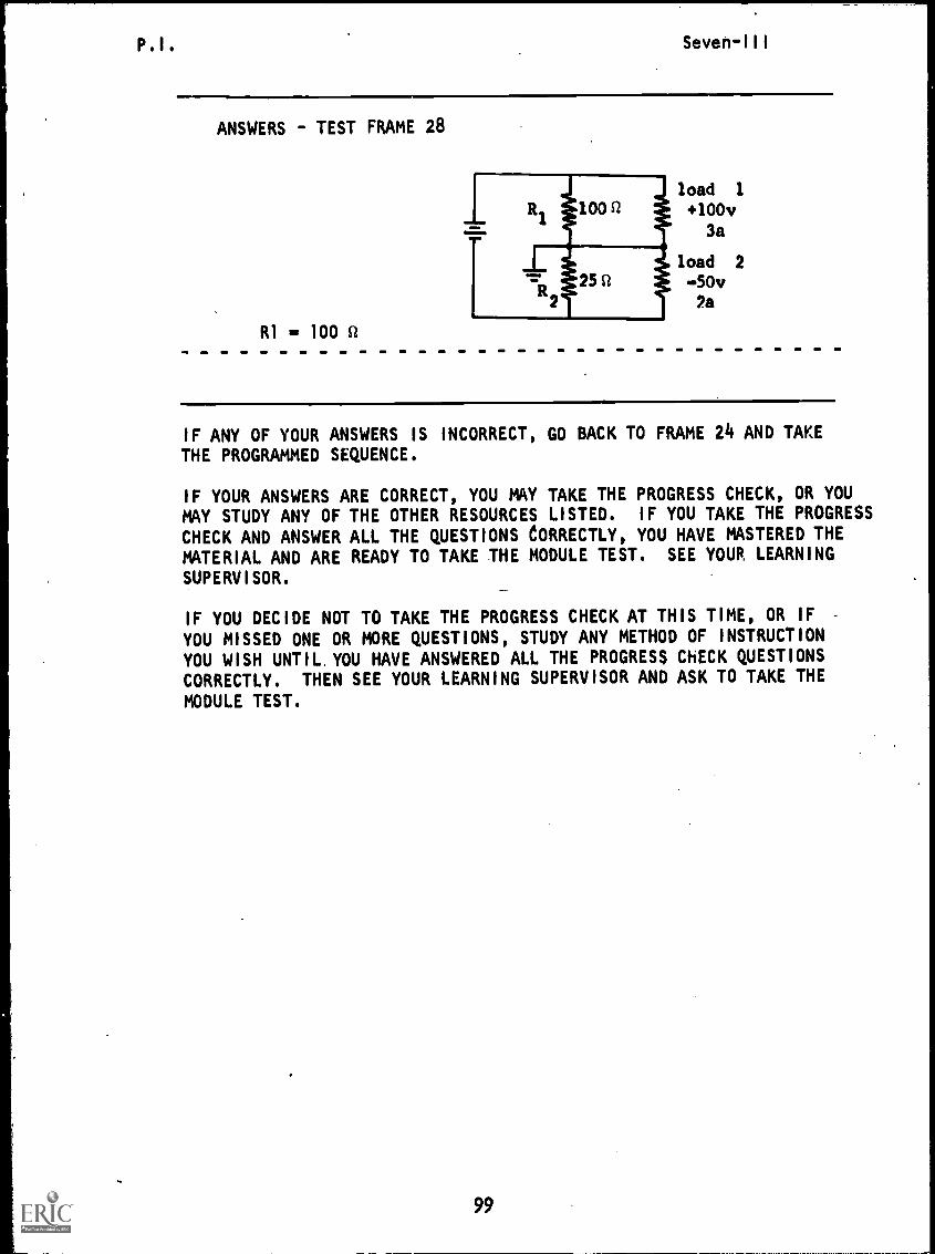
P.I. Seven-III
ANSWERS - TEST FRAME 28
RI = 100 Q
load 1
+100v3a
load 2
-50v'a
IF ANY OF YOUR ANSWERS IS INCORRECT, GO BACK TO FRAME 24 AND TAKETHE PROGRAMMED SEQUENCE.
IF YOUR ANSWERS ARE CORRECT, YOU MAY TAKE THE PROGRESS CHECK, OR YOUMAY STUDY ANY OF THE OTHER RESOURCES LISTED. IF YOU TAKE THE PROGRESS
CHECK AND ANSWER ALL THE QUESTIONS CORRECTLY, YOU HAVE MASTERED THEMATERIAL AND ARE READY TO TAKE THE MODULE TEST. SEE YOUR LEARNING
SUPERVISOR.
IF YOU DECIDE NOT TO TAKE THE PROGRESS CHECK AT THIS TIME, OR IF
YOU MISSED ONE OR MORE QUESTIONS, STUDY ANY METHOD OF INSTRUCTIONYOU WISH UNTIL. YOU HAVE ANSWERED ALL THE PROGRESS ChECK QUESTIONS
CORRECTLY. THEN SEE YOUR LEARNING SUPERVISOR AND ASK TO TAKE THE
MODULE TEST.
99
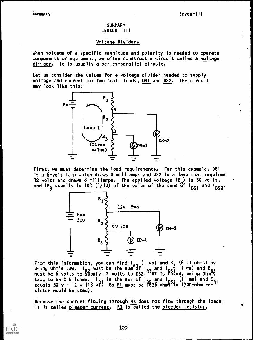
'r
Summary Seven-III
SUMMARYLESSON III
Voltage Dividers
When voltage of a specific magnitude and polarity is needed to operatecomponents or equipment, we often construct a circuit called a voltagedivider. It is usually a series-parallel circuit.
Let us consider the values for a voltage divider needed to supplyvoltage and current for two small loads, DS1 and DS2. The circuitmay look like this:
na-
11MM.imma
Loop 1
R3
1Givenvalue)
MINI1110
DS-2
First, we must determine the load requirements, For this example, DS1
is a 6-volt lamp which draws 2 milliamps and DS2 is a lamp that requires12-volts and draws 8 milliam s. The applied voltage (Ea) is 30 volts,
and IR3usually is 10% (1 /10) of the value of the sums of !Dv and !rm.
DS .'2
From this information, you can find IR2 (1 ma) and R2 (6 kilohms) byusing Ohm's Law. I must be the sum off I
R3and I
D 1J (3 ma) and ER 2
must be 6 volts to Opply 12 volts to DS2. R2 is ro5 regund, using Oh
Law, to be 2 kilohms. I is the sum of I and Ins (1.1 ma) and ER1
equals 30 v - 12 v (18 4. So RI must be T636 ohmg la 1700rohm re-sistor would be used).
Because the current flowing through R3 does not flow through the loads,
it is called bleeder current. R3 is called the bleeder resistor.
100
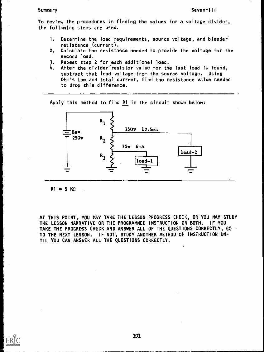
Summary Seven-III
To review the procedures in finding the values for a voltage divider,the following steps are used.
1. Determine the load requirements, source voltage, and bleederresistance (current).
2. Calculate the resistance needed to provide the voltage for thesecond load.
3. Repeat step 2 for each additional load.4. After the divider/resistor value for the last load is found,
subtract that load voltage from the source voltage. Using
Ohm's Law and total current, find the resistance value neededto drop this difference.
Apply this method to find R1 in the circuit shown below:
'load2 1
R1 = 5 KO
AT THIS POINT, YOU MAY TAKE THE LESSON PROGRESS CHECK, OR YOU MAY STUDYTHE LESSON NARRATIVE OR THE PROGRAMMED INSTRUCTION OR BOTH. IF YOU
TAKE THE PROGRESS CHECK AND ANSWER ALL OF THE QUESTIONS CORRECTLY, GOTO THE NEXT LESSON. IF NOT, STUDY ANOTHER METHOD OF INSTRUCTION UN-TIL YOU CAN ANSWER ALL THE QUESTIONS CORRECTLY.
101