doc342.53.80536 tl2360 - hach company
TRANSCRIPT

DOC342.53.80536
TL236003/2021, Edition 5
User Manual


Table of ContentsSection 1 Specifications ........................................................................................ 3Section 2 General information ............................................................................ 4
2.1 Safety information................................................................................................. 52.1.1 Use of hazard information.......................................................................... 52.1.2 Precautionary labels ................................................................................... 52.1.3 Certification.................................................................................................52.1.4 Korean certification..................................................................................... 6
2.2 Product overview.................................................................................................. 62.3 Product components ............................................................................................. 7
Section 3 Installation ............................................................................................... 83.1 Installation guidelines........................................................................................... 83.2 Connect to external devices (optional) ................................................................. 8
Section 4 Startup .......................................................................................................9Section 5 User interface and navigation ........................................................ 9Section 6 Operation ............................................................................................... 11
6.1 Configure the instrument settings....................................................................... 116.1.1 Configure the measurement settings........................................................126.1.2 Add operator IDs...................................................................................... 126.1.3 Add sample IDs........................................................................................ 13
6.1.3.1 Import sample IDs (optional) .......................................................... 136.2 Calibrate the turbidimeter with StablCal Standards............................................ 14
6.2.1 Calibration notes.......................................................................................146.2.2 Prepare the StablCal standards............................................................... 146.2.3 Configure the calibration settings............................................................. 156.2.4 StablCal calibration procedure................................................................. 166.2.5 StablCal standards storage...................................................................... 17
6.3 Calibration verification........................................................................................ 176.3.1 Optical system check................................................................................176.3.2 Configure the verification settings............................................................ 186.3.3 Gelex notes.............................................................................................. 186.3.4 Measure the Gelex secondary turbidity standards................................... 186.3.5 Verification procedure...............................................................................19
6.4 Turbidity measurement ....................................................................................... 206.4.1 Measurement notes.................................................................................. 206.4.2 Sample collection..................................................................................... 216.4.3 Clean the sample cell ............................................................................... 216.4.4 Turbidity measurement procedure............................................................22
6.5 Absorbance and transmittance measurement .................................................... 236.5.1 Measurement notes.................................................................................. 236.5.2 Absorbance and transmittance measurement procedure.........................24
6.6 Data management .............................................................................................. 246.6.1 Show the recorded data........................................................................... 246.6.2 Send data to a connected device............................................................. 256.6.3 Delete data from the data log................................................................... 256.6.4 Backup the instrument settings................................................................ 25
1

6.7 Measurement techniques................................................................................... 256.7.1 Ratio on or off ........................................................................................... 266.7.2 Indexing a single sample cell ....................................................................266.7.3 Matching sample cells .............................................................................. 276.7.4 Prepare dilution water ...............................................................................296.7.5 Using a flow cell ........................................................................................29
6.7.5.1 Prepare the flow cell ....................................................................... 306.7.5.2 Flow cell operation......................................................................... 316.7.5.3 Adjust the flow................................................................................ 316.7.5.4 Flow cell maintenance.................................................................... 316.7.5.5 Clean a flow cell assembly ............................................................. 316.7.5.6 Flow cell storage............................................................................ 31
6.7.6 Remove air bubbles from the sample....................................................... 316.7.7 Prevent condensation on a sample cell .................................................... 326.7.8 Using the air purge system....................................................................... 326.7.9 Use a cell adapter .....................................................................................33
Section 7 Maintenance ......................................................................................... 347.1 Clean spills ......................................................................................................... 347.2 Clean the instrument ...........................................................................................347.3 Instrument utilities ............................................................................................... 347.4 Install an instrument update................................................................................34
Section 8 Troubleshooting ................................................................................. 35Section 9 Replacement parts and accessories ........................................ 37
Table of Contents
2

Section 1 SpecificationsSpecifications are subject to change without notice.
Specification Details
Measurement method Nephelometric
Regulatory Meets ISO 7027, DIN EN 27027 and DIN 38404 ASTM D7315 - Standard Test Method for Determination of TurbidityAbove 1 Turbidity Unit (TU) in Static ModeASTM D6855 - Standard Test Method for Determination of TurbidityBelow 5 NTU in Static Mode
Dimensions (W x D x H) 39.5 x 30.5 x 15.3 cm (15.6 x 12.0 x 6.02 in.)
Weight 2.9 kg (6.4 lb)
Enclosure IP30; indoor use only
Protection Class External power supply: Protection Class I; instrument: Protection Class II
Pollution degree 2
Installation category External power supply: Category II; instrument: Category I
Power requirements Instrument: 12 VDC, 3.4 A; power supply: 100–240 VAC, 50/60 Hz
Operating temperature 0 to 40 °C (32 to 104 °F)
Storage temperature –20 to 60 °C (–4 to 140 °F)
Humidity 5 to 95% relative humidity, non-condensing
Display 17.8 mm (7 in.) color touch screen
Light source Light-emitting diode (LED) at 860 ± 30 nm
Measurement units FNU, NTU, EBC, Abs (absorbance), %T (% transmittance) and mg/L(degree)
Range FNU (Ratio on): 0–1000 FNU (Ratio off): 0–40 NTU (Ratio on): 0–10,000 auto decimalNTU (Ratio off): 0–40 EBC (Ratio on): 0–2450 auto decimalEBC (Ratio off): 0–9.8 Absorbance (auto range): 0–2.00 Transmittance (%): 1.0–100 Degree: 0–100 mg/L
English 3

Specification Details
Accuracy1, 2, 3 FNU4: ±2% of reading plus 0.01 FNU from 0–1000 FNUNTU4: ±2% of reading plus 0.01 NTU from 0–1000 NTU, ±5% of readingfrom 1000–4000 NTU, ±10% of reading from 4000–10,000 NTUAbsorbance: ±0.005 Abs from 0–1 Abs at 860 nmTransmittance: 0.12% T from 10–100% T at 860 nm
Resolution Turbidity: 0.001 FNU/NTU/EBCAbsorbance: 0.001 AbsTransmittance: 0.1% T
Repeatability ±1% of reading or 0.01 FNU/NTU, whichever is greater (under referenceconditions)
Response time Signal averaging off: 6.8 secondsSignal averaging on: 14 seconds (when 10 measurements are used tocalculate the average)
Stabilization time Immediately
Reading modes Single, continuous, Rapidly Settling Turbidity™, signal averaging on oroff, ratio on or off
Communication USB
Interface 2 USB-A ports for USB flash drive, Seiko DPU-S445 printer, keyboardand barcode scanner
Datalog Maximum 2000 total logs, includes reading log, verification log andcalibration log
Air purge Dry nitrogen or instrument grade air (ANSI MC 11.1, 1975)0.1 scfm at 69 kPa (10 psig); 138 kPa (20 psig) maximumHose barb connection for 1/8-inch tubing
Sample cells Round cells 95 x 25 mm (3.74 x 1 in.) borosilicate glass with rubber-linedscrew capsNote: Smaller sample cells (less than 25 mm) can be used when a cell adapter is used.
Sample requirements 25 mm sample cell: 20 mL minimum0 to 70 °C (32 to 158 °F)
Certification CE, KC, RCM
Warranty 1 year (EU: 2 years)
Section 2 General informationIn no event will the manufacturer be liable for direct, indirect, special, incidental or consequentialdamages resulting from any defect or omission in this manual. The manufacturer reserves the right tomake changes in this manual and the products it describes at any time, without notice or obligation.Revised editions are found on the manufacturer’s website.
1 Turbidity specifications identified using recently prepared formazin standard and matched 25-mm sample cells.
2 Reference conditions: 23 ± 2 °C, 50 (± 10)% RH noncondensing, 100–240 VAC, 50/60 Hz3 Intermittent electromagnetic radiation of 3 volts/meter or greater may cause slight accuracy
shifts.4 FNU is equivalent to NTU in the Ratio off mode.
4 English

2.1 Safety informationThe manufacturer is not responsible for any damages due to misapplication or misuse of this productincluding, without limitation, direct, incidental and consequential damages, and disclaims suchdamages to the full extent permitted under applicable law. The user is soley responsible to identifycritical application risks and install appropriate mechanisms to protect processes during a possibleequipment malfunction.Please read this entire manual before unpacking, setting up or operating this equipment. Payattention to all danger and caution statements. Failure to do so could result in serious injury to theoperator or damage to the equipment.Make sure that the protection provided by this equipment is not impaired. Do not use or install thisequipment in any manner other than that specified in this manual.
2.1.1 Use of hazard information
D A N G E R Indicates a potentially or imminently hazardous situation which, if not avoided, will result in death orserious injury.
W A R N I N G Indicates a potentially or imminently hazardous situation which, if not avoided, could result in deathor serious injury.
C A U T I O N Indicates a potentially hazardous situation that may result in minor or moderate injury.
N O T I C E Indicates a situation which, if not avoided, may cause damage to the instrument. Information thatrequires special emphasis.
2.1.2 Precautionary labelsRead all labels and tags attached to the instrument. Personal injury or damage to the instrumentcould occur if not observed. A symbol on the instrument is referenced in the manual with aprecautionary statement.
This symbol, if noted on the instrument, references the instruction manual for operationand/or safety information.
This symbol indicates the presence of a light source that may have the potential to causeminor eye injury. Obey all messages that follow this symbol to avoid potential eye injury.
Electrical equipment marked with this symbol may not be disposed of in Europeandomestic or public disposal systems. Return old or end-of-life equipment to themanufacturer for disposal at no charge to the user.
2.1.3 Certification
EN 55011/CISPR 11 Notification WarningThis is a Class A product. In a domestic environment this product may cause radio interference inwhich case the user may be required to take adequate measures.Canadian Radio Interference-Causing Equipment Regulation, ICES-003, Class A:Supporting test records reside with the manufacturer.
English 5
This Class A digital apparatus meets all requirements of the Canadian Interference-CausingEquipment Regulations.Cet appareil numérique de classe A répond à toutes les exigences de la réglementation canadiennesur les équipements provoquant des interférences.FCC Part 15, Class "A" LimitsSupporting test records reside with the manufacturer. The device complies with Part 15 of the FCCRules. Operation is subject to the following conditions:
1. The equipment may not cause harmful interference.2. The equipment must accept any interference received, including interference that may cause
undesired operation.
Changes or modifications to this equipment not expressly approved by the party responsible forcompliance could void the user's authority to operate the equipment. This equipment has been testedand found to comply with the limits for a Class A digital device, pursuant to Part 15 of the FCC rules.These limits are designed to provide reasonable protection against harmful interference when theequipment is operated in a commercial environment. This equipment generates, uses and canradiate radio frequency energy and, if not installed and used in accordance with the instructionmanual, may cause harmful interference to radio communications. Operation of this equipment in aresidential area is likely to cause harmful interference, in which case the user will be required tocorrect the interference at their expense. The following techniques can be used to reduceinterference problems:
1. Disconnect the equipment from its power source to verify that it is or is not the source of theinterference.
2. If the equipment is connected to the same outlet as the device experiencing interference, connectthe equipment to a different outlet.
3. Move the equipment away from the device receiving the interference.4. Reposition the receiving antenna for the device receiving the interference.5. Try combinations of the above.
2.1.4 Korean certification
업무용을 위한 EMC 등급 A 장치에 대한사용자 지침사용자안내문
A 급 기기 ( 업무용 방송통신기자재 )이 기기는 업무용 (A 급 ) 전자파적합기기로서 판매자 또는 사용자는 이 점을 주의하시기 바라며 , 가정외의 지역에서 사용하는 것을 목적으로 합니다.
2.2 Product overviewC A U T I O N
Fire hazard. This product is not designed for use with flammable liquids.
The TL2360 laboratory turbidimeter measures the scattered light from water samples to determinethe turbidity value of the samples. In the ratio-on mode, the instrument uses multiple detectors atdifferent angles to correct for interferences and to increase the measurement range. In the ratio-offmode, the instrument uses one detector at a 90-degree angle from the light source. The user cancalibrate the instrument and verify the calibration at regular intervals.The user interface uses a touch screen display. A Seiko DPU-S445 printer, USB flash drive orkeyboard can connect to the USB ports. Refer to Figure 1. The real-time clock with battery puts atime-date stamp on all of the data that is transmitted or recorded (i.e., reading log, calibration log andverification log).
6 English

Figure 1 Product overview
1 Sample compartment lid 6 Power connection2 Touch screen display 7 USB port3 Sample cell holder 8 Power button4 Lamp cover 9 USB port5 Air purge
2.3 Product componentsMake sure that all components have been received. Refer to Figure 2. If any items are missing ordamaged, contact the manufacturer or a sales representative immediately.
English 7

Figure 2 Instrument components
1 Silicone oil 6 StablCal Calibration kit2 Oiling cloth 7 Power supply3 TL2360 turbidimeter 8 Power cord4 1-inch sample cells (30 mL) with caps (6x) 9 Dust cover5 Gelex secondary turbidity standardization kit
Section 3 InstallationC A U T I O N
Multiple hazards. Only qualified personnel must conduct the tasks described in thissection of the document.
This instrument is rated for an altitude of 3100 m (10,710 ft) maximum. Use of this instrument at analtitude higher than 3100 m can slightly increase the potential for the electrical insulation to breakdown, which can result in an electric shock hazard. The manufacturer recommends that users withconcerns contact technical support.
3.1 Installation guidelinesInstall the instrument:
• On a level surface• In a clean, dry, well ventilated, temperature controlled location• In a location with minimum vibrations that has no direct exposure to sunlight• In a location where there is sufficient clearance around it to make connections and to do
maintenance tasks• In a location where the power button and power cord are visible and easily accessible
3.2 Connect to external devices (optional)Use the USB ports to connect the instrument to a Seiko DPU-S445 printer, barcode handsetscanner, USB flash drive or keyboard. Refer to Figure 1 on page 7. The maximum length of a
8 English

connected USB cable is 3 m (9.8 ft). As an alternative to the touchscreen, use a keyboard to entertext into text boxes on the display (e.g., passwords and sample IDs).
Section 4 StartupC A U T I O N
Infrared Light Hazard. The infrared light produced by this instrument can cause eye injury. Theinfrared light source in this instrument only receives power when the sample cell cover is closed.
Refer to the illustrated steps that follow to supply power to the instrument and start the instrument.The self-check will start.
Section 5 User interface and navigationThe instrument display is a touch screen. Only use a clean, dry finger tip to navigate the functions ofthe touch screen. Do not use writing tips of pens or pencils or other sharp objects to make selectionson the screen or damage to the screen will occur.Refer to Figure 3 for an overview of the home screen.
English 9
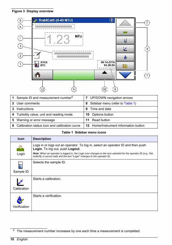
Figure 3 Display overview
1 Sample ID and measurement number5 7 UP/DOWN navigation arrows2 User comments 8 Sidebar menu (refer to Table 1)3 Instructions 9 Time and date4 Turbidity value, unit and reading mode 10 Options button5 Warning or error message 11 Read button6 Calibration status icon and calibration curve 12 Home/Instrument information button
Table 1 Sidebar menu icons
Icon Description
Login
Logs in or logs out an operator. To log in, select an operator ID and then pushLogin. To log out, push Logout.Note: When an operator is logged in, the Login icon changes to the icon selected for the operator ID (e.g., fish,butterfly or soccer ball) and the text "Login" changes to the operator ID.
Sample ID
Selects the sample ID.
Calibration
Starts a calibration.
Verification
Starts a verification.
5 The measurement number increases by one each time a measurement is completed.
10 English

Table 1 Sidebar menu icons (continued)
Icon Description
Data Log
Shows the reading log, calibration log and verification log. Refer to Show therecorded data on page 24.
Setup
Configures the instrument settings. Refer to Configure the instrument settingson page 11.
Diagnostics
Shows the firmware information, instrument backup, instrument updates, signalinginformation and factory service data.
Timer
Sets a timer.
Section 6 Operation
6.1 Configure the instrument settings
1. Push , then push Setup.2. Select an option.
Option Description
Location Sets the location name of the instrument. The location is sent withmeasurements to the USB drive. The location is not saved to the data log.
Date & Time Sets the date format, the time format and the date and time. Enter thecurrent date and time. Date Format—Sets the date format. Options: dd-mm-yyyy (default), yyyy-mm-dd, dd-mm-yyyy or mm-dd-yyyy. Time Format—Sets the time format. Options: 12 or 24 hours (default).
Security Enables or disables password protection for the settings and tasks in thesecurity list. Security Password—Sets or changes the security(administrator) password (10 characters maximum). Passwords are casesensitive. Security List—Sets the security level for each setting and task inthe security list.
• Off—All operators can change the setting or do the task.• One key—Only operators with a one-key or two-key security level can
change the setting or do the task. Refer to Add operator IDs on page 12.• Two keys—Only operators with a two-key security level can change the
setting or do the task.
Note: The Security setting is not set to on until Close is pushed.
Sound Settings Enables or disables the sound settings for individual events. To enable ordisable all of the sound settings, select All and then push Setup.
English 11

Option Description
Peripherals Shows the connection status of attached devices such as a Seiko DPU-S445 printer, USB memory (flash drive) or keyboard.
PowerManagement
Sets when the instrument is automatically set to sleep mode or off after aperiod of no activity. Sleep Timer—Sets when the instrument is set to sleepmode. Options: OFF, 30 minutes, 1 (default), 2 or 12 hours.
6.1.1 Configure the measurement settingsSelect the reading mode, measurement units, data log settings and more.
1. At the main reading screen, push Options>Reading Setup.2. Select an option.
Option Description
ReadingMode
Sets the reading mode to single, continuous or RST mode. Single (default)—Themeasurement stops when the reading is stable. Continuous—The measurementcontinues until the user pushes Done. RST—The Rapidly Settling Turbidity (RST)mode calculates and continuously updates the turbidity reading of the sample to aconfidence of 95%, based on the accumulated trend of the real time measuredvalues. The RST mode is best used on samples that settle rapidly andcontinuously change in value. The reading is based on a correctly preparedsample that is homogeneous at the beginning of the reading. It is best applied tosamples that are greater than 20 NTU. The sample must be mixed thoroughly byinversion immediately before inserting it into the instrument. Signal Avg—Theturbidity reading that shows on the display is an average of the values measuredduring the time interval selected. Options: For single measurement mode, 5 to15 seconds. For continuous measurement mode, 5 to 90 seconds.
Unit Selects the measurement units that show on the display and that are recorded tothe data log. Options: NTU (default), FNU, EBC, Abs or %T.
Ratio Sets the ratio mode to on (default) or off. When set to off, an indicator shows onthe reading window.Note: The ratio off mode is only valid for turbidity measurements that are less than 40 NTU.
BubbleReject
Sets the bubble reject to on (default) or off. When set to on, high turbidity readingscaused by bubbles in the sample are not shown or saved to the data log.
Data LogSetup
Sets the data log settings. Auto Store—Measurement data is automaticallyrecorded in the reading log. Default: On. If Auto Store is off, push Options>Store tomanually save a reading in the data log. Send Data Format—Sets the outputformat of measurement data that is sent to external devices (CSV, XML or BMP).Default: XML. Print Format—Sets the output format of measurement data that issent to a printer (Quick Print or Detailed Print (GLP)). Comments—Lets users addcomments to log entries. Auto Send—Measurement data is automatically sent toall of the devices (e.g., printer and USB flash drive) that are connected to theinstrument after each measurement. Options: Off, new file or continue file: off—donot auto send data, new file—send data and save it in a new file, continue file—send data and save all data in one file.
6.1.2 Add operator IDsAdd a unique operator ID for each person who will measure samples (30 maximum). Select an icon,operator password and security level for each operator ID.
1. Push Login.2. Push Options>New.3. Enter a new operator ID (20 characters maximum), then push OK.
12 English

4. Push the LEFT and RIGHT arrows to select the icon for the operator ID (e.g., fish, butterfly orsoccer ball).
5. Push Operator Password, then enter a password for the operator ID.Note: Passwords are case sensitive.
6. Push Security Level, then select the security level for the operator ID.
• Off—The operator cannot change the settings or do the tasks in the Security settings that havea security level of one key or two keys.
• One key—The operator can change all the settings and do all the tasks in the Security settingsthat have a security level of off or one key.
• Two keys—The operator can change all the settings and do all the tasks in the Securitysettings.
Note: Before a security level can be selected, the Security setting must be set to on. Refer to Configure theinstrument settings on page 11.
7. Push OK>Close.8. To edit an operator ID, select the operator ID and then push Options>Edit.9. To delete an operator ID, select the operator ID and then push Options>Delete>OK.
6.1.3 Add sample IDsAdd a unique sample ID for each sample (1000 maximum). The sample ID identifies the samplelocation or other sample specific information.As an alternative, import sample IDs from a spreadsheet file to the instrument. Refer to Importsample IDs (optional) on page 13.
1. Push Sample ID.2. Push Options>New.3. Enter a new sample ID (20 characters maximum).4. Push OK.5. Select an option.
Option Description
Add Date/Time Adds the date and time that the sample was collected to the sample ID(optional). The date and time entered for each sample ID show on the SampleID menu.
Add Number Adds a measurement number to the sample ID (optional). Select the firstnumber used for the measurement number (0 to 999).The measurement number shows in parenthesis after the sample ID on thehome screen. Refer to User interface and navigation on page 9.
Add Color Adds a colored circle to the sample ID icon (optional). The sample ID iconshows before the sample ID on the home screen. Refer to User interface andnavigation on page 9.
6. Push OK>Close.7. To edit a sample ID, select the sample ID and then push Options>Edit>OK.8. To delete a sample ID, select the sample ID and then push Options>Delete>OK.
Note: To delete all sample ID's, select the sample ID and then push Options>Delete All Sample IDs>OK.
6.1.3.1 Import sample IDs (optional)Import sample IDs from a spreadsheet file on a USB flash drive.Note: Imported sample IDs cannot be edited.
English 13

1. On a PC, make a new spreadsheet file.2. At the top of the first column, enter #Reading Number,#Sample ID,#Date and Time for the
heading.3. Enter the information for one sample ID in each row after the heading. Make sure that there are
no spaces.Example:#Reading Number,#Sample ID,#Date and Time0,Aeration,13.09.2016 10:030,Outlet,13.09.2016 06:300,Feed,13.09.2016 18:00Note: The date of sample collection is optional.
4. Make a new folder on a USB flash drive. Give the folder the name "SampleID".5. Save the spreadsheet file to the SampleID folder as a CSV (comma-separated value) or TXT
(text) file.6. Connect the USB flash drive to a USB port on the instrument.7. On the instrument, push Sample ID>Options>Import Sample ID list.
The filename of the spreadsheet file(s) in the SampleID folder shows.8. Select the applicable spreadsheet file, then push OK.
The sample IDs are added to the instrument.
6.2 Calibrate the turbidimeter with StablCal StandardsCalibrate the turbidimeter before it is used for the first time using the StablCal sealed vial standardsprovided.Calibrate the turbidimeter at least every 3 months or as specified by the regulating authority whendata is used for ISO 7027 reporting.Note: Unknown results may occur if standards other than the recommended calibration points are used. Therecommended calibration points (< 0.1, 20, 200, 1000, 4000 and 7500 NTU) provide the best calibration accuracy.Use of standards other than StablCal, or user-prepared formazin, may result in less accurate calibrations. Themanufacturer cannot guarantee the performance of the instrument if calibrated with co-polymerstyrenedivinylbenzene beads or other suspensions.
6.2.1 Calibration notes
• Make sure that the instrument is in the same ambient conditions as where it is used.• Make sure that the standards are at the same ambient temperature as the instrument before use.• Use only the provided silicone oil. This silicone oil has the same refractive index as the vial glass
and masks minor glass differences and scratches.• Store the oiling cloth in a plastic storage bag to keep the cloth clean.• If power is lost during calibration, the new calibration data is lost and the last calibration data is
used.• In Calibration mode, automatic range and signal averaging on are selected. When calibration is
completed, all operational modes go back to the last settings.• All nephelometric (turbidity units of measure) calibrations are done at the same time.• Ratio-on and Ratio-off calibration data is measured and recorded at the same time.• The FNU values of StablCal standards and formazin standards are calculated using the
conversion factors of 1 FNU = 1 NTU.
6.2.2 Prepare the StablCal standardsWhen received and at intervals:
1. Clean the exterior surface of the StablCal vials with laboratory glass cleaning detergent.2. Rinse the vials with distilled or deionized water.3. Dry the vials with a lint-free cloth.
14 English

Note: Never shake or invert the < 0.1 NTU standard. If the standard has been mixed or shaken, do not move thevial for 15 minutes or more before using.Note: Do not remove the caps from the sealed vials.
Make sure that the StablCal standards are at ambient instrument temperature before use (and nogreater than 40 °C (104 °F)).Invert the standards (except < 0.1 NTU) before use. Refer to the user instructions that are suppliedwith the StablCal standards.
6.2.3 Configure the calibration settingsChange the calibration settings as necessary before the instrument is calibrated. The instrumentmust be calibrated when the calibration curve is changed.
1. Push Calibration.2. Push Options>Calibration Setup.3. Select the calibration curve range and type of calibration standard.
Option Description
StablCal RapidCal(0–40 NTU)
Calibration with 20-NTU StablCal standard (default).Note: The dark current in the instrument is used as the zero point of thecalibration curve. The calibration curve is linear from 0-40 NTU, thus lowturbidity measurements are very accurate.
StablCal (0–10000NTU)
Full-range calibration (<0.1 NTU, 20 NTU, 200 NTU, 1000 NTU,4000 NTU, 7500 NTU) with StablCal.
Formazin RapidCal(0–40 NTU)
Calibration with 20-NTU formazin standard.Note: The dark current in the instrument is used as the zero point of thecalibration curve. The calibration curve is linear from 0-40 NTU, thus lowturbidity measurements are very accurate.
Formazin (0–10000NTU)
Full-range calibration (20 NTU, 200 NTU, 1000 NTU, 4000 NTU,7500 NTU and dilution water) with formazin.
Degrees (0–100 mg/L) Full-range calibration (20 mg/L, 100 mg/L and dilution water) withkaolin.
SDVB (0–10000 NTU) Full-range calibration (20 NTU, 200 NTU, 1000 NTU, 4000 NTU,7500 NTU and dilution water) with spherical styrene divinylbenzene.
EU Pharm (0–30 NTU) Full-range calibration (<0.1 NTU, 3 NTU, 6 NTU, 18 NTU, 30 NTU).
Custom Calibration The user can enter a custom calibration for turbidity. The user selectsthe number of calibration standards and the value of each calibrationstandard. Use a custom calibration when smaller sample cells areused with a sample cell adapter.
4. Select the remaining calibration options.
Option Description
Verify after Cal. Sets the instrument to start a verification immediately after the instrumentis calibrated. When set to on, the verification standard is measuredimmediately after a calibration is done. The value of the verificationstandard shows on the display as the last standard during calibration.
CalibrationReminder
Sets the time interval between calibrations. When a calibration is due, thedisplay will show a reminder and a question mark on the calibration icon atthe top of the display. Options: Off (default), 1 day, 7 days, 30 days or90 days. When a calibration is done, the calibration time is set to zero.
Reset to FactoryCalibration
Sets the calibration settings to the factory defaults.
English 15

6.2.4 StablCal calibration procedure
1. Push Login andselect the applicableOperator ID. If loginis not necessary, goto step 3.
2. Push Login andenter the password.Push OK.
3. PushCalibration. Thestandard values forthe selectedcalibration curve(and verificationstandard, if Verifyafter Cal is on) showon the display. Toselect a differentcalibration curve,refer to Configurethe calibrationsettings on page 15.
4. Get the StablCalstandard that showson the display. Cleanthe vial with a soft,lint-free cloth toremove water spotsand fingerprints.
5. Apply a smalldrop of silicone oilfrom the top to thebottom of the vial.
6. Use the oilingcloth to apply the oilequally to thesurface of the vial.Remove most of theoil. Make sure thatthe vial is almost dry.
7. Carefully andslowly invert the vialto fully mix thestandard (do notinvert the <0.1 NTUvial). Be careful notto add air bubbles.
8. Put the vial in thesample cell holderwith the triangle onthe vial aligned withthe reference markon the sample cellholder. Push the lidclosed until a click isheard.
16 English
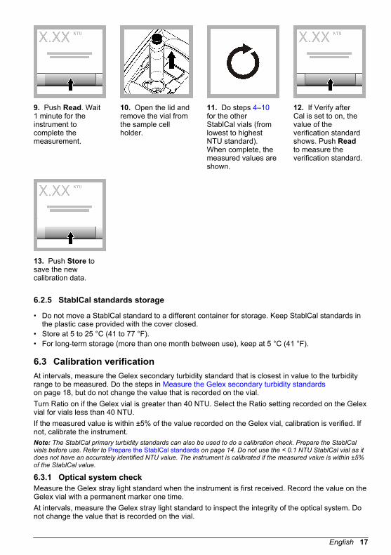
9. Push Read. Wait1 minute for theinstrument tocomplete themeasurement.
10. Open the lid andremove the vial fromthe sample cellholder.
11. Do steps 4–10for the otherStablCal vials (fromlowest to highestNTU standard).When complete, themeasured values areshown.
12. If Verify afterCal is set to on, thevalue of theverification standardshows. Push Readto measure theverification standard.
13. Push Store tosave the newcalibration data.
6.2.5 StablCal standards storage
• Do not move a StablCal standard to a different container for storage. Keep StablCal standards inthe plastic case provided with the cover closed.
• Store at 5 to 25 °C (41 to 77 °F).• For long-term storage (more than one month between use), keep at 5 °C (41 °F).
6.3 Calibration verificationAt intervals, measure the Gelex secondary turbidity standard that is closest in value to the turbidityrange to be measured. Do the steps in Measure the Gelex secondary turbidity standardson page 18, but do not change the value that is recorded on the vial.Turn Ratio on if the Gelex vial is greater than 40 NTU. Select the Ratio setting recorded on the Gelexvial for vials less than 40 NTU.If the measured value is within ±5% of the value recorded on the Gelex vial, calibration is verified. Ifnot, calibrate the instrument.Note: The StablCal primary turbidity standards can also be used to do a calibration check. Prepare the StablCalvials before use. Refer to Prepare the StablCal standards on page 14. Do not use the < 0.1 NTU StablCal vial as itdoes not have an accurately identified NTU value. The instrument is calibrated if the measured value is within ±5%of the StablCal value.
6.3.1 Optical system checkMeasure the Gelex stray light standard when the instrument is first received. Record the value on theGelex vial with a permanent marker one time.At intervals, measure the Gelex stray light standard to inspect the integrity of the optical system. Donot change the value that is recorded on the vial.
English 17

If the value measured is similar to the value recorded on the Gelex stray light standard (within±0.02 NTU), the instrument works correctly. If not, contact Customer Service.
6.3.2 Configure the verification settingsSelect the acceptance range and measurement units for calibration verification and more.
1. Push Verification.2. Push Options>Verification Setup.3. Select an option.
Option Description
SecondaryStandard
Sets the value of the verification standard. Enter the value of the Gelex vialor StablCal standard to be used for verification.
Verify after Cal. Sets the instrument to start a verification immediately after the instrument iscalibrated. When set to on, the verification standard is measuredimmediately after a calibration is done.
AcceptanceRange
Value—Sets the maximum difference permitted between the recordedvalue of the verification standard and the measured value of the verificationstandard during verification. Unit—Sets the acceptance range forverification to a percentage (1 to 20%) or an NTU value (0.001 to 20% ofthe maximum range limit). Options: % or NTU.
VerificationReminder
Sets the time interval between calibration verifications. The display willshow a reminder when a verification is due. Options: OFF(default), 1 day,7 days, 30 days or 90 days. When a verification is done, the verificationtime is set to zero.
6.3.3 Gelex notes
• Measure the Gelex secondary standards on the instrument on which they will be used. Themeasured values can only be used for one instrument due to small differences in glass andinstrument optical systems.
• Do not keep a Gelex vial in the instrument for more time than is necessary to completemeasurement. The heat from the lamp can change the turbidity value of a Gelex vial.
• Keep the Gelex standards at room temperature. Do not let Gelex standards freeze or becomewarmer than 50 °C (122 °F). High temperatures may cause Gelex suspensions to divide.
• Make sure that the Gelex standards are at ambient instrument temperature before measurement.
6.3.4 Measure the Gelex secondary turbidity standardsPre-requisites: Make sure that the units show NTU and Signal Avg is not selected. Record if theratio mode is on or off. Refer to Configure the measurement settings on page 12.Measure the Gelex secondary turbidity standards each time the instrument is calibrated and recordthe new values on the Gelex vials with a water soluble marker.
18 English

1. Clean the Gelexvials with a soft, lint-free cloth to removewater spots andfingerprints.
2. Apply a smalldrop of silicone oilfrom the top to thebottom of the vial.
3. Use the oilingcloth to apply the oilequally to thesurface of the vial.Remove most of theoil. Make sure thatthe vial is almost dry.
4. Put the 0–2 NTUGelex vial in thesample cell holderwith the triangle onthe vial aligned withthe reference markon the sample cellholder. Push the lidclosed until a click isheard.
5. When the value isstable, push Read.
6. Open the lid andremove the vial fromthe instrument.
7. Record the valueon the whitediamond space onthe vial using awater solublemarker.Record on the vial ifRatio was on or offwhen the vial wasmeasured.
8. Do all steps againfor the other Gelexvials (but not thestray light standard).Measure from lowestto highest NTU.
6.3.5 Verification procedureUse the verification procedure to measure the same Gelex or StablCal vial at regular intervals todetermine if the reading stays within the acceptance range. Use the Verification Setup menu to set areminder for the verification.
English 19

1. Push Login andselect the applicableOperator ID. If loginis not necessary, goto step 3.
2. Push Login andenter the password.Push OK.
3. Push Verification.The verificationstandard value isshown. PushOptions>VerificationSetup to change thevalue of theverification standard.
4. Clean the Gelexvials with a soft, lint-free cloth to removewater spots andfingerprints.
5. Apply a smalldrop of silicone oilfrom the top to thebottom of the vial.
6. Use the oilingcloth to apply the oilequally to thesurface of the vial.Remove most of theoil. Make sure thatthe vial is almost dry.
7. Put the vial in thesample cell holderwith the triangle onthe vial aligned withthe reference markon the sample cellholder. Push the lidclosed until a click isheard.
8. Push Read. Thevalue and pass orfail status shows.The data isautomatically storedin the instrument.
6.4 Turbidity measurementFor accurate turbidity readings use clean sample cells and remove air bubbles. Refer to Clean thesample cell on page 21 and Remove air bubbles from the sample on page 31.
6.4.1 Measurement notesProper measurement techniques are important in minimizing the effects of instrument variation, straylight and air bubbles. For accurate and repeatable measurements:Instrument
• Make sure that the instrument is on a level, stationary surface that is free of vibration during themeasurement.
• Instrument stabilization is immediate. No warm-up time is necessary.• Always close the sample compartment lid during measurement, calibration and verification.• Remove the sample cell from the instrument and turn off the instrument if the instrument is stored
for an extended time period (more than a month).• Keep the sample compartment lid closed to keep dust and dirt out.
Sample cells
• Always cap the sample cell to prevent spillage of the sample into the instrument.
20 English
• Always use clean sample cells in good condition. Dirty, scratched or damaged cells can result inreadings that are not accurate.
• Make sure that cold samples do not “fog” the sample cell. Refer to Prevent condensation on asample cell on page 32.
• Store sample cells filled with distilled or deionized water and cap tightly.• For the best accuracy, use a single sample cell for every measurement or a flow cell.
Note: As an alternative, matched sample cells may be used for measurements but do not provide as good ofaccuracy or precision as a single indexed sample cell or flow cell. When using matched sample cells, align theorientation mark on the sample cell with the reference mark on the sample cell holder.
Measurement
• Measure samples immediately to prevent temperature changes and settling. Before ameasurement is taken, always make sure that the sample is homogeneous throughout.
• Avoid sample dilution when possible.• Avoid instrument operation in direct sunlight.
6.4.2 Sample collection
• Collect samples in clean glass or plastic bottles with tight-fitting caps.• Rinse the container a minimum of three times with the sample.• When collecting a sample from a water tap in a distribution system or treatment plant, turn the
water on for at least five minutes, then collect the sample. Do not adjust the flow because this canadd particles.
• When collecting a sample from a body of water (e.g., a stream or storage tank), collect at least oneliter (1 quart) and fully mix before taking an aliquot for measurement. If the quality of the samplesource is not constant, collect samples at many locations at different depths as necessary. Then,mix the samples together to prepare one sample for measurement.
• Fill the container. Let the container overflow with the sample and then immediately put the cap onthe sample container so that there is no headspace (air) above the sample.
• Write the sample information on the container.• Start analysis as soon as possible to prevent temperature changes, bacteria growth and settling.
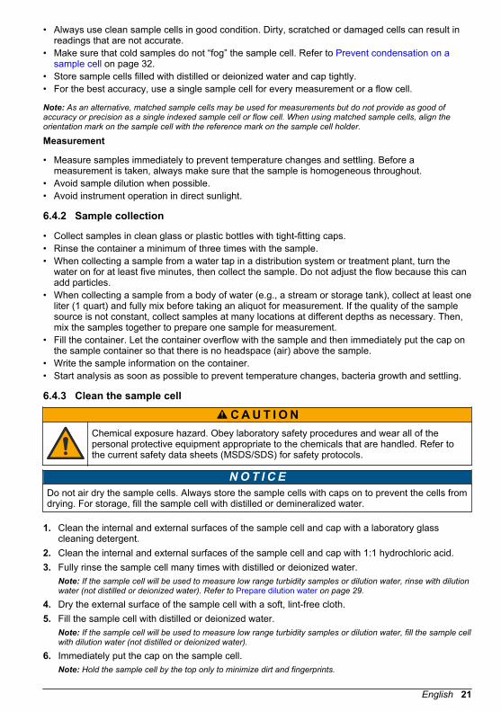
6.4.3 Clean the sample cell
C A U T I O N Chemical exposure hazard. Obey laboratory safety procedures and wear all of thepersonal protective equipment appropriate to the chemicals that are handled. Refer tothe current safety data sheets (MSDS/SDS) for safety protocols.
N O T I C E Do not air dry the sample cells. Always store the sample cells with caps on to prevent the cells fromdrying. For storage, fill the sample cell with distilled or demineralized water.
1. Clean the internal and external surfaces of the sample cell and cap with a laboratory glasscleaning detergent.
2. Clean the internal and external surfaces of the sample cell and cap with 1:1 hydrochloric acid.3. Fully rinse the sample cell many times with distilled or deionized water.
Note: If the sample cell will be used to measure low range turbidity samples or dilution water, rinse with dilutionwater (not distilled or deionized water). Refer to Prepare dilution water on page 29.
4. Dry the external surface of the sample cell with a soft, lint-free cloth.5. Fill the sample cell with distilled or deionized water.
Note: If the sample cell will be used to measure low range turbidity samples or dilution water, fill the sample cellwith dilution water (not distilled or deionized water).
6. Immediately put the cap on the sample cell.Note: Hold the sample cell by the top only to minimize dirt and fingerprints.
English 21

6.4.4 Turbidity measurement procedureTo include an operator ID and sample ID with the measurement data, refer to Add sample IDson page 13 and Add operator IDs on page 12.
1. Push Login andselect the applicableOperator ID. If loginis not necessary, goto step 3.
2. Push Login andenter the password.Push OK.
3. Push Sample ID.Select the applicablesample ID, thenpush Select. Theselected sample IDshows on thedisplay.
4. Rinse a clean,empty sample celltwo times with thesolution to bemeasured and drainto waste. Fill to theline (about 30 mL)with sample andimmediately put thecap on the samplecell.
5. Clean the samplecells with a soft, lint-free cloth to removewater spots andfingerprints.
6. Apply a smallbead of silicone oilfrom the top to thebottom of the samplecells.
7. Use the oilingcloth provided toapply the oil equallyto the surface of thesample cells.Remove the excessoil. Make sure thatthe sample cells arealmost dry.
8. Gently and slowlyinvert the samplecell to fully mix thesample. Be carefulnot to add airbubbles.
22 English

9. Put the samplecell in the samplecell holder with thetriangle on thesample cell alignedwith the referencemark on the samplecell holder. Push thelid closed until a clickis heard.
10. Push Read (orDone if incontinuous mode).Wait for theinstrument to readthe sample.Note: If auto store isoff, push Options >Store to save the data.
6.5 Absorbance and transmittance measurement6.5.1 Measurement notesFor the best accuracy and reproducibility:
• Absorbance and transmittance can only be measured at 860 nm.• Set the zero reference point before measurement. Set the zero reference point again when the
instrument is not used for some time as shown in Absorbance and transmittance measurementprocedure on page 24.
• Absorbance and transmittance measurements use the same zero reference point. Absorbanceand transmittance are measured on a single sample after setting a zero reference point.
• Use a flow cell for measurements. A flow cell is necessary to get the accuracy and reproducibilityspecifications shown in Specifications on page 3.If a flow cell is not used, use a single indexed sample cell or matched sample cells. Use theabsorbance or transmittance mode to match the sample cells. Refer to Matching sample cellson page 27.
• Refer to Measurement notes on page 20 for more measurement notes.
English 23

6.5.2 Absorbance and transmittance measurement procedureNote: To measure samples with negative absorbance, set the analytical zero using the sample with the greatestabsorbance, and measure the sample with the least absorbance. Report the reading as negative absorbance.
1. PushOptions>ReadingSetup. Set the unitsto Abs (or %T).Close the ReadingSetup.
2. Insert the samplecell with the zerosolution into the cellholder. Close the lid.
3. Push Zero. Thedisplay shows0.000 Abs (or 100%T).
4. Open the lid andremove the zerosolution from thesample cell holder.
5. Insert the samplecell with the sampleinto the cell holder.
6. Push Read tomeasure the value.
7. PushOptions>Store tosave the value.
6.6 Data management6.6.1 Show the recorded dataAll the recorded data is kept in the data log. There are three types of data logs:
• Reading log—Shows the recorded measurements.• Calibration log—Shows the calibration history.• Verification log—Shows the verification history.
1. Push Data Log and select the applicable data log.2. To show the details of a log entry, select the log entry and then push View Details.
Note: To add a comment to the log entry, push the comments icon.
3. To show only some of the data, push Filter, then select On. The Filter Settings window opens.4. Select an option.
Option Description
Time Interval Selects only the data that was stored during a specific time interval.
Operator ID Selects only the data that was stored with a specific operator ID.
Sample ID Selects only the data from the Reading Log that was stored with a specificsample ID.
24 English

6.6.2 Send data to a connected deviceThe instrument can send data to a USB memory device or Seiko DPU-S445 printer. For best results,use only USB 2.0 memory devices. The instrument makes a logger folder on the device and savesthe data as a .bmp, .csv or .xml file.
1. Connect a USB memory device or cable to a USB port on the instrument.2. Connect the other end of the cable to the printer, if applicable. Refer to Figure 4.3. Go to Setup>Peripherals. The connection status shows Connected. If the status shows Not
Connected, make sure to use the recommended devices.4. Push Data Log and select the applicable log.5. To send only some of the data, use the filter settings or select a single data point. Refer to Show
the recorded data on page 24.6. Push Options>Send Data Log. Select single data point, filtered data or all data. Push OK.
The instrument sends the selected data to the connected devices.
Figure 4 Connect the printer to the instrument
6.6.3 Delete data from the data logThe instrument automatically deletes the oldest data record when the data log is full. The user canalso delete data manually. Make sure to save the data to an external device, then delete the data inthe data log.
1. Push Data Log and select the applicable log.2. To delete only some of the data, use the filter settings. Refer to Show the recorded data
on page 24.3. To delete the data, push Options>Delete Data. Select single data point, filtered data or all data.
Push OK.The instrument deletes the selected data from the data log.
6.6.4 Backup the instrument settingsSave instrument settings such as Operator ID to a USB memory device, then install the settings on adifferent instrument of the same model.
1. Install a USB memory device in the USB port on the instrument.2. Push Settings>Instrument Backup. Push OK. The settings are saved to the USB memory
device.
6.7 Measurement techniquesMeasurements may be made with different operation mode settings and optional accessories.
English 25
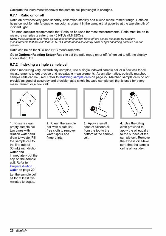
Calibrate the instrument whenever the sample cell pathlength is changed.
6.7.1 Ratio on or offRatio on provides very good linearity, calibration stability and a wide measurement range. Ratio onhelps correct for interference when color is present in the sample that absorbs at the wavelength ofincident light.The manufacturer recommends that Ratio on be used for most measurements. Ratio must be on tomeasure samples greater than 40 NTUs (9.8 EBCs).Note: Measurements with Ratio on and measurements with Ratio off are almost the same for turbiditymeasurements that are less than 40 NTU if interferences caused by color or light absorbing particles are notpresent.
Ratio can be on for NTU and EBC measurements.Go to Options>Reading Setup>Ratio to set the ratio mode on or off. When set to off, the displayshows Ratio: Off.
6.7.2 Indexing a single sample cellWhen measuring very low turbidity samples, use a single indexed sample cell or a flow cell for allmeasurements to get precise and repeatable measurements. As an alternative, optically matchedsample cells can be used. Refer to Matching sample cells on page 27. Matched sample cells do notprovide as good of accuracy and precision as a single indexed sample cell that is used for everymeasurement or a flow cell.
1. Rinse a clean,empty sample celltwo times withdilution water anddrain to waste. Fillthe sample cell tothe line (about30 mL) with dilutionwater andimmediately put thecap on the samplecell. Refer to Prepare dilutionwater on page 29.Let the sample cellsit for at least fiveminutes to degas.
2. Clean the samplecell with a soft, lint-free cloth to removewater spots andfingerprints.
3. Apply a smallbead of silicone oilfrom the top to thebottom of the samplecell.
4. Use the oilingcloth provided toapply the oil equallyto the surface of thesample cell. Removethe excess oil. Makesure that the samplecell is almost dry.
26 English

5. Put the samplecell in the samplecell holder. Push thelid closed until a clickis heard.Record the valuewhen stable.
6. Remove thesample cell, turn itabout 1/8 of a turnand put it in thesample cell holderagain. Push the lidclosed until a click isheard.Record the valuewhen stable.
7. Repeat step 6until the lowest valueis shown on thedisplay.
8. Put an orientationmark on the markingband near the top ofthe sample cellwhere the lowestvalue is shown.
6.7.3 Matching sample cellsTo decrease the effects that optical differences among sample cells can have on turbidity,transmittance or absorbance measurements, measure samples in matched sample cells. It may notbe possible to match all sample cells due to the differences in glass.
1. Rinse two ormore clean, emptysample cells twotimes with dilutionwater and drain towaste. Fill thesample cells to theline (about 30 mL)with filtered dilutionwater andimmediately put thecap on the samplecell. Refer to Prepare dilutionwater on page 29.Let the sample cellsit for at least fiveminutes to degas.
2. Clean the samplecells with a soft, lint-free cloth to removewater spots andfingerprints. Do notinvert the samplecell.
3. Apply a smallbead of silicone oilfrom the top to thebottom of the samplecells.
4. Use the oilingcloth provided toapply the oil equallyto the surface of thesample cells.Remove the excessoil. Make sure thatthe sample cells arealmost dry.
English 27
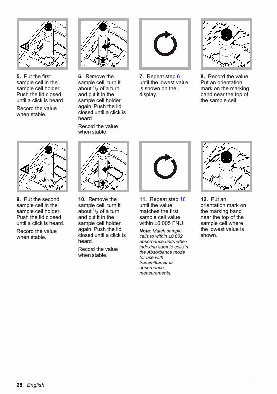
5. Put the firstsample cell in thesample cell holder.Push the lid closeduntil a click is heard.Record the valuewhen stable.
6. Remove thesample cell, turn itabout 1/8 of a turnand put it in thesample cell holderagain. Push the lidclosed until a click isheard.Record the valuewhen stable.
7. Repeat step 6until the lowest valueis shown on thedisplay.
8. Record the value.Put an orientationmark on the markingband near the top ofthe sample cell.
9. Put the secondsample cell in thesample cell holder.Push the lid closeduntil a click is heard.Record the valuewhen stable.
10. Remove thesample cell, turn itabout 1/8 of a turnand put it in thesample cell holderagain. Push the lidclosed until a click isheard.Record the valuewhen stable.
11. Repeat step 10until the valuematches the firstsample cell valuewithin ±0.005 FNU.Note: Match samplecells to within ±0.002absorbance units whenindexing sample cells inthe Absorbance modefor use withtransmittance orabsorbancemeasurements.
12. Put anorientation mark onthe marking bandnear the top of thesample cell wherethe lowest value isshown.
28 English

13. Do steps 9–12again as necessaryto match the othersample cellsprepared in steps 1–4.
6.7.4 Prepare dilution waterDilution water is used when indexing a sample cell or matching sample cells and to prepare formazinstandards.
1. Collect at least 1000 mL of high-quality, low-turbidity water (i.e., distilled, demineralized ordeionized water or filtered tap water).
2. Measure the turbidity of the water using the turbidimeter. Refer to Turbidity measurementon page 20.
3. If the turbidity of the water is greater than 0.5 NTU, filter the water using the sample filtration anddegassing kit. Refer to the user instructions provided with the sample filtration and degassing kit.
6.7.5 Using a flow cell
C A U T I O N Do not use a flow cell with flammable samples or those that contain hydrocarbons, solvents,concentrated acids or concentrated bases that may damage wetted parts of the cells. Conduct testsbefore use of flow cells if sample compatibility is not known.
Note: Do not use a high pressure flow cell kit with this instrument.
Use a flow cell to increase the speed, accuracy and reproducibility of measurement. Themanufacturer especially recommends using a flow cell for low turbidity measurements. Refer to Figure 5.A flow cell must be used to get the accuracy and reproducibility values in Specifications on page 3 forabsorbance or transmittance measurements.
English 29

Figure 5 Flow cell
1 Drain tube 5 Flow cell cover2 Inlet reservoir 6 Flow cell3 Reservoir cover 7 Flow cell assembly4 Collection drain assembly 8 Support stand base
6.7.5.1 Prepare the flow cell
1. Fully clean the flow cell. Refer to Clean a flow cell assembly on page 31.2. Assemble the flow cell, tubing and stand. Refer to the user instructions that are supplied with the
flow cell.3. Fill the flow cell and tubing with water and make sure that there are no leaks or air bubbles.
Note: Air bubbles collect in areas that are not cleaned fully.
4. Clean the exterior surface of the flow cell with a soft, lint-free cloth to remove water spots andfingerprints.
5. Apply a small bead of silicone oil from the top to the bottom of the flow cell.Note: Use only the provided silicone oil. This silicone oil has the same refractive index as the flow cell glassand masks minor glass scratches.
6. Use the oiling cloth provided to apply the oil equally to the surface of the flow cell. Remove theexcess oil. Make sure that the flow cell is almost dry.Note: Put the oiling cloth in a plastic storage bag to keep the cloth clean.
30 English

6.7.5.2 Flow cell operation
• Do not use the flow cell for samples that contain large particles that may collect and stop thesample from flowing.
• Slowly pour the sample down the interior edge of the inlet reservoir to prevent mixing of thesample, which can cause air bubbles. Air bubbles create a false positive interference in a turbiditymeasurement.
• If bubbles collect in the flow cell, gently tap the flow cell on a soft surface to remove the bubbles. Ifbubbles continue to collect in the flow cell, put the glass flow cell in liquid detergent for 24 hoursand then rinse fully.
• When measuring many samples of different turbidity, measure the samples in order of the cleanest(lowest turbidity) to the dirtiest (highest turbidity) to prevent contamination from one sample to thenext.
• The flow-cell cover must be in place for the LED light source to function.
6.7.5.3 Adjust the flowTo set the flow rate, increase the height of the collection drain assembly on the support rod todecrease the flow rate. Make sure that the bottom of the collection drain assembly is no lower than7.5 cm (3 in.) above the support stand base.To flush the flow cell, lower the collection drain assembly to the support stand base to flush the flowcell.
6.7.5.4 Flow cell maintenance
• Keep all parts of the flow cell assembly clean.• At intervals, replace all the tubing to make sure that the system is clean. Keep the tubing as short
as possible to minimize air locking and lag time of sample flow. Locate the instrument as close tothe drain as possible.
6.7.5.5 Clean a flow cell assembly
1. Disassemble the flow cell assembly.2. Clean the inside and outside of the glass parts with a laboratory glass cleaning detergent. Follow
with multiple rinses with distilled or demineralized water.Note: All tubing, flow cells, and caps in the flow cell assembly can also be steam sterilized.
3. If measuring low turbidity samples, clean the inside and outside of the glass parts with1:1 hydrochloric acid and rinse multiple times with dilution water.
4. Fill the sample cell with distilled or demineralized water and immediately put the caps on thesample cell.
5. Clean the inside and outside of the plastic parts and tubing with laboratory detergent and warmwater.Note: At intervals, replace the tubing as contaminants, including microbiological growths, are difficult to removefrom the inside surface of the tubing.
6. Air dry the parts after cleaning.
6.7.5.6 Flow cell storage
• Install the reservoir cover when the system is not in use to prevent contamination of the system byairborne particles.
• For short-term storage (a few hours), flush the system with distilled or deionized water and leavethe flow cell full of the flush water to minimize air locks and build up of residue on the parts.
• For long-term storage, disassemble, fully clean and air dry all parts.
6.7.6 Remove air bubbles from the sampleAir bubbles can cause unstable readings. Use a degassing method to remove air or other gases fromthe sample before measurement even if no bubbles are seen.
English 31

The methods typically used for degassing are:
• Let the sample stand for several minutes• Apply a vacuum• Use the sample degassing kit• Use an ultrasonic bath
Let the samples stand for several minutes, then gently invert two or three times before measurement.In some cases, more than one method may be necessary to remove bubbles (e.g., the use of heatwith an ultrasonic bath may be necessary in some severe conditions). Use care with these methodsas sample turbidity can be changed if these methods are not used correctly.
6.7.7 Prevent condensation on a sample cellCondensation may occur on the outside of the sample cell when measuring a cold sample in a warm,humid environment. This condensation or fogging of the sample cell interferes with turbiditymeasurement.To prevent condensation:
• Make sure that the outside of the sample cell is dry before measurement.• Use the air purge system as necessary. Refer to Using the air purge system on page 32.• If condensation occurs while using the air purge system, warm the sample slightly. Let the sample
sit at room temperature or partially put the sample into a warm water bath for a short time. Gentlyinvert the sample cell before measurement.
Note: Warming may change the sample turbidity. Measure the sample without warming when possible.
6.7.8 Using the air purge systemThe air purge system is used to keep condensation off the external surface of the sample cell whencold samples are measured.The air purge system pushes dry air through the optical compartment to keep the outside of thesample cell dry. The connection is made at the air purge fitting on the back of the instrument. Referto Product overview on page 6.Use dry nitrogen or instrument grade air (ANSI MC 11.1, 1975) at no greater than 138 kPa (20 psig).The manufacturer recommends an air consumption rate of 3 to 10 SCFH (standard cubic feet/hour).When the sample temperature is about or less than 2 °C (35 °F), use a desiccant dryer and particlefilter to make sure that the dew point of the air purge is less than the sample temperature. The airdryer must contain a desiccant with a color indicator. Replace the desiccant when the indicatorchanges color.If only shop air is available, use a coalescing filter with an automatic drain and a dryer and particlefilter to get instrument quality air. Use a coalescing filter that typically operates for greater than2000 hours. Replace the particle filter when the air dryer is replaced.Figure 6 shows the methods for connecting the two types of air supply to the instrument.Note: The dryer and filter are not necessary if dry nitrogen is used.
32 English

Figure 6 Air purge connections
1 Particle filter (Balston DFU 9933- 05-BQ orequivalent)
6 Shop air
2 Air dryer (Balston DAU 9933- 05-101 orequivalent)
7 Filter (Balston 100-12-BX or equivalent)
3 Pressure regulator 8 Auto drain (Balston 20-105 or equivalent)4 Instrument air 9 Filter housing (Balston FR-920-30 or
equivalent)5 Coalescing filter/regulator (0–30 psig)
6.7.9 Use a cell adapterMany different test tubes, sample cells and ampules can be used to measure samples when a celladapter is used. Refer to Figure 7. Use a cell adapter when the diameter of the test tube, sample cellor ampule is less than 25 mm. Refer to Accessories on page 38 for the cell adapter.
Figure 7 Cell adapter
Use a cell adapter when:
• Only a small quantity of sample is available.• The sample to be measured is in an ampule that cannot be opened.
English 33

Refer to the user instructions that are supplied with the adapter for installation instructions. Use onlytest tubes and sample cells that are free of significant scratches. Clean and apply silicone oil to allsample cells, test tubes and ampules used with the cell adapter. Refer to Clean the sample cellon page 21.
Section 7 MaintenanceC A U T I O N
Multiple hazards. Only qualified personnel must conduct the tasks described in thissection of the document.
7.1 Clean spillsC A U T I O N
Chemical exposure hazard. Dispose of chemicals and wastes in accordance with local,regional and national regulations.
1. Obey all facility safety protocols for spill control.2. Discard the waste according to applicable regulations.
7.2 Clean the instrumentClean the exterior of the instrument with a moist cloth, and then wipe the instrument dry.
7.3 Instrument utilities
1. Push Home to see the instrument model, version, serial number and location name.2. Push Diagnostics.3. Select an option.
Option Description
Factory Service For factory/service use only.
InstrumentBackup
Store—Saves a backup of all the instrument settings and log files to aUSB flash drive. Restore—Copies the instrument settings and log filesfrom a USB flash drive to the instrument. Overwrites all the instrumentsettings.
InstrumentUpdate
Installs an instrument update on the instrument from a USB flash drive.
Service Time Shows the date entered for the last service date and for the next servicedate. When set to on, a service reminder shows on the display whenservice is due.
7.4 Install an instrument updateFind the instrument update file on the product website. Save the file from the website to a USB flashdrive, then do the steps that follow to install the update.
1. Push Diagnostics>Instrument Update.2. Put the USB flash drive into the rear USB port of the instument. Push OK. The update starts.
Note: Use only the rear USB port of the instrument for the update.
3. Wait for the instrument to power off and on. Remove the USB flash drive.
34 English

Section 8 TroubleshootingMessage Solution
Startup
The self-check stopped.Close the lid.
Close the lid. Push Close.
The self-check stopped.Hardware error.
Set the power to off, wait 20 seconds and then set the power to onagain. If the self check is not successful, record the error number andcontact technical support.Error numbers: 0: RTC; 1: Touch IC; 2: Slide door; 3: Dark voltage—Close the door until a click is heard. Start the instrument again. 4:Amplifier coefficient—Make sure that the power supply is connected toan electrical outlet that has a protective earth ground. 5: Infrared LEDvoltage; 6: Infrared LED current; 8: Transmission voltage drift—If thelamp was replaced, calibrate the instrument. If a vial was in thesample compartment during the self-test at startup, remove the vial. 9:SDRAM; 10: NOR flash; 11: SPI flash; 12: Battery voltage; 13: Powersupply voltage—Make sure that the correct power supply is used.
Next calibration is due! Calibrate the instrument. Refer to Calibrate the turbidimeter withStablCal Standards on page 14.Note: The calibration reminder is set to on. Refer to Configure the calibration settingson page 15.
Next service is due! Contact technical support.Note: The service reminder is set to on. Refer to Instrument utilities on page 34.
Next verification is due! Do a calibration verification. Refer to Calibration verificationon page 17.Note: The verification reminder is set to on. Refer to Configure the verification settingson page 18.
Reading
Hardware error /instrument error
Set the power to off, wait 20 seconds and then set the power to onagain. If the problem continues, contact technical support.
The calibration range isexceeded.
The measured turbidity is more than the calibration range of theinstrument. Select a calibration curve for the full measurement range.Refer to Configure the calibration settings on page 15.
The measurement rangeis exceeded.
The measured turbidity is more than the measurement range of theinstrument.
Calibration/Verification
Instrument error Examine the standards. Start the calibration or verification again.If calibration (or verification) is not successful, contact technicalsupport.
The standard is not stable. Use the correct calibration standards. Invert the standard until nobubbles or large particles show.
The standard value is outof the measurementrange.
Use the correct calibration standards. Invert the standards. Make sureto measure the standards in ascending order.
English 35

Message Solution
The standard value is toolow.
The wrong calibration standard is in the vial compartment. Make surethat the standard has not expired.Put the correct calibration standard in the vial compartment. Makesure to invert the standard.
The standard value is toohigh.
The wrong calibration standard is in the vial compartment. Make surethat the standard has not expired.Put the correct calibration standard in the vial compartment.
Verification failed. Examine the verification standard. Calibrate the instrument. Refer to Calibrate the turbidimeter with StablCal Standards on page 14.If verification is not successful after calibration, contact technicalsupport.
Instrument update
Copy from USB Memoryfailed
Remove large files from the USB flash drive that use too much space.Start the instrument update procedure again.Remove the instrument update files from the USB flash drive. Savethe instrument update files again to the USB flash drive.Connect the USB flash drive to the instrument. Start the instrumentupdate procedure again.
Instrument update file ismissing
Remove the instrument update files from the USB flash drive. Savethe instrument update files again to the USB flash drive.Connect the USB flash drive to the instrument. Start the instrumentupdate procedure again.
Instrument update file iscorrupt
Not enough memory toupdate the instrument
Contact technical support.
USB memory is notconnected.
Connect a USB flash drive to the instrument. Make sure that the filesystem "FAT32" is installed on the USB flash drive.Set the power to off, wait 20 seconds and then set the power to onagain. Connect the USB flash drive. Start the instrument updateprocedure again.
Read/Write to USB flash drive
Cannot write to USBmemory
Connect a USB flash drive to the instrument. Make sure that the filesystem "FAT32" is installed on the USB flash drive.Set the power to off, wait 20 seconds and then set the power to onagain. Look for remaining space on the USB flash drive.Set the power to off, wait 20 seconds and then set the power to onagain. Connect the USB flash drive to the instrument.
Cannot read from USBmemory
Restore backup
No instrument backup isavailable.
Connect a USB flash drive to the instrument. Make sure that the filesystem "FAT32" is installed on the USB flash drive.Set the power to off, wait 20 seconds and then set the power to onagain. Connect the USB flash drive. Start the instrument updateprocedure again.
Not able to restore thebackup
Security
Invalid password Enter the correct password. If the password is lost, contact technicalsupport.
36 English

Message Solution
Send data
Connect a receivingdevice.
Examine the device connections. Set the Auto Send setting to off.Refer to Configure the measurement settings on page 12.
Add sample IDs from list
No valid data found No sample ID file was found on the USB flash drive.
Not able to read samplingdate.
Make sure that the date and time format is dd.mm.yyyy hh:mm.
The instrument cannotread the Sample ID
Examine the text strings. Refer to Import sample IDs (optional)on page 13.
Problem/Error: IncorrectdatePossible cause: Thewrong date format.
Make sure that the date and time format is dd.mm.yyyy hh:mm.
The sample ID list full.Data has not been added.
Remove the sample IDs that are not used. Add a new sample ID.
Section 9 Replacement parts and accessoriesNote: Product and Article numbers may vary for some selling regions. Contact the appropriate distributor or refer tothe company website for contact information.
Recommended standards
Description Quantity Item no.
Calibration kit, StablCal, sealed sample cells (<0.1, 20, 200,1000, 4000 and 7500 NTU) 1 2659505
Gelex secondary turbidity standardization kit(stray light standard and 0–2, 0–20, 0–200, 200-4000, and4,000–10,000 NTU)
1 2589200
Replacement parts
Description Quantity Item no.
Dust cover 1 9649100
Oiling cloth 1 4707600
Power cord, North America, 125 VAC 1 1801000
Power cord, European, 250 VAC 1 4683600
Power supply 1 9673701
Sample cells, 30 mL, 1 in. round glass 6 2084900
Silicone oil 1 126936
English 37

Accessories
Description Quantity Item no.
Calibration kit, StablCal, 100 mL each(<0.1, 20, 200, 1000, 4000 and 7500 NTU)
1 2659510
Calibration kit, StablCal, 500 mL each(<0.1, 20, 200, 1000, 4000 and 7500 NTU)
1 2659500
Filter disks, 0.2 micron 10/pkg 2323810
Filter, membrane (without pad), 0.45 micron, 47 mm 200/pkg 1353001
Filter paper, glass fiber, 1.5 micron, 47 mm 100 253000
Formazin stock solution, 4000 NTU 100 mL 246142
Formazin stock solution, 4000 NTU 500 mL 246149
Formazin high-range turbidity standard, 7500 NTU ampule 1 2584202
Sample cells, 2.5–5 mL, 11-mm precision round glass, withcaps 25/pkg LYY622
Sample cell adapter, 11 mm 1 LPZ444.99.00001
Sample degassing kit 1 4397500
Sample degassing and filtration kit 1 4397510
0.1 NTU, StablCal™ low-level turbidity verification standards(not for instrument calibration) 100 mL 2723342
0.3 NTU, StablCal™ low-level turbidity verification standards(not for instrument calibration) 100 mL 2697942
0.5 NTU, StablCal™ low-level turbidity verification standards(not for instrument calibration) 100 mL 2698042
TenSette® Pipet, 1.0-10.0 mL, 1 1970010
TenSette® Pipet Tips 250 2199725
Volumetric flask, 100 mL, Class A 1 1457442
Volumetric flask, 200 mL, Class A 1 1457445
38 English


*DOC342.53.80536*
HACH COMPANY World HeadquartersP.O. Box 389, Loveland, CO 80539-0389 U.S.A.Tel. (970) 669-3050(800) 227-4224 (U.S.A. only)Fax (970) [email protected]
HACH LANGE GMBHWillstätterstraße 11D-40549 Düsseldorf, GermanyTel. +49 (0) 2 11 52 88-320Fax +49 (0) 2 11 52 [email protected]
HACH LANGE Sàrl6, route de Compois1222 VésenazSWITZERLANDTel. +41 22 594 6400Fax +41 22 594 6499
© Hach Company/Hach Lange GmbH, 2016, 2018, 2020, 2021.All rights reserved.