doc.: ieee 802.11-18/xxxxr0€¦ · web view4.3real world implementations of full duplex ... of...
TRANSCRIPT

July, 2018 doc.: IEEE 802.11-18/xxxxr0
IEEE P802.11Wireless LANs
Text Contributions to the FD-TIG Technical Report regarding
Full Duplex for 802.11
Date: 2018-06-01
Author(s):Name Affiliation Address Phone email
Allen D. Heberling GenXcomm 1604 San Antonio St. Austin,
TX, 78701Allen.heberling@gen
xcomminc.com
Submission page 1
AbstractThis document contains text contributions to be considered for inclusion in the FD-TIG Technical Report.
ChairJames Gilb
EditorsAllen D. Heberling

July, 2018 doc.: IEEE 802.11-18/xxxxr0
This Page Intentionally Blank.
Submission page 2
July, 2018 doc.: IEEE 802.11-18/xxxxr0
Table of Contents1. Introduction............................................................................................................................................52. FD use cases...........................................................................................................................................53. Full Duplex(FD) functional requirements.............................................................................................6
3.1 Support for legacy 802.11 devices.................................................................................................63.2 IEEE 802.11 Channels and bandwidths of FD operations.............................................................6
3.2.1 2.4 GHz..................................................................................................................................63.2.2 5 GHz.....................................................................................................................................7
3.3 System Performance....................................................................................................................113.3.1 Maximum Effective Throughput rate per BSS....................................................................113.3.2 Reduction in Latency between FD enabled STAs and AP..................................................113.3.3 Hidden node mitigation........................................................................................................11
3.4 Receiver Requirements................................................................................................................113.4.1 Reflection/Echo Cancellation..............................................................................................113.4.2 Self-interference cancellation..............................................................................................11
4.0 Technical Feasibility..............................................................................................................................134.1 Current instantiations of Full Duplex PHY functionality............................................................144.2 Current simulations of Full Duplex MAC functionality..............................................................144.3 Real world Implementations of Full Duplex operations..............................................................15
4.3.1 Full Duplex DOCSIS 3.1-FDX............................................................................................158.0 Economic Feasibility...........................................................................................................................179.0 Recommendation(s)...............................................................................................................................19
References:...............................................................................................................................................20
Submission page 3

July, 2018 doc.: IEEE 802.11-18/xxxxr0
This Page Intentionally Blank.
Submission page 4

July, 2018 doc.: IEEE 802.11-18/xxxxr0
1. Introduction Need text here.
2. FD use cases
Submission page 5

July, 2018 doc.: IEEE 802.11-18/xxxxr0
3. Full Duplex(FD) functional requirements
3.1 Support for legacy 802.11 devices Any IEEE 802.11 device (e.g. STA or AP) that supports full duplex functionality shall be able to operate in a heterogeneous 802.11 network populated with a variety of 802.11 devices defined in the IEEE Std 802.11 2016 (e.g. .11n(HT), .11ac(VHT), …) and the IEEE P802.11ax/D3.0 (i.e. HEW WLAN).
3.2 IEEE 802.11 Channels and bandwidths of FD operations
3.2.1 2.4 GHzFull Duplex capability shall be operational in these existing IEEE 802.11 2.4 GHz channels and bandwidths:
11b DSSS 11 g/n OFDM 11n OFDM
Ch. Idx
Min (MHz
)
Fc (MHZ
)
Max (MHz
)
BW (MHz
)Ch. Idx
Min (MHz)
Fc (MHZ)
Max (MHz)
BW (MHz)
Ch. Idx
Min (MHz)
Fc (MHZ)
Max (MHz)
BW (MHz)
2401 2402 24020 2407 0 2407 0 24071 2401 2412 2423 22 1 2402 2412 2422 20 1 24122 2417 2 2417 2 24173 2422 3 2422 3 2402 2422 2442 404 2427 4 2427 4 24275 2432 5 2422 2432 2442 20 5 24326 2426 2437 2448 22 6 2437 6 24377 2442 7 2442 7 24428 2447 8 2447 8 24479 2452 9 2442 2452 2462 20 9 245210 2457 10 2457 10 245711 2451 2462 2473 22 11 2462 11 2442 2462 2482 4012 2467 12 2467 12 246713 2472 13 2462 2472 2482 20 13 2472
2482 2482
Submission page 6

July, 2018 doc.: IEEE 802.11-18/xxxxr0
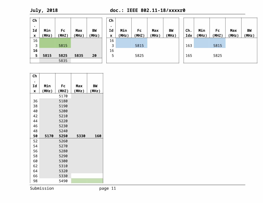
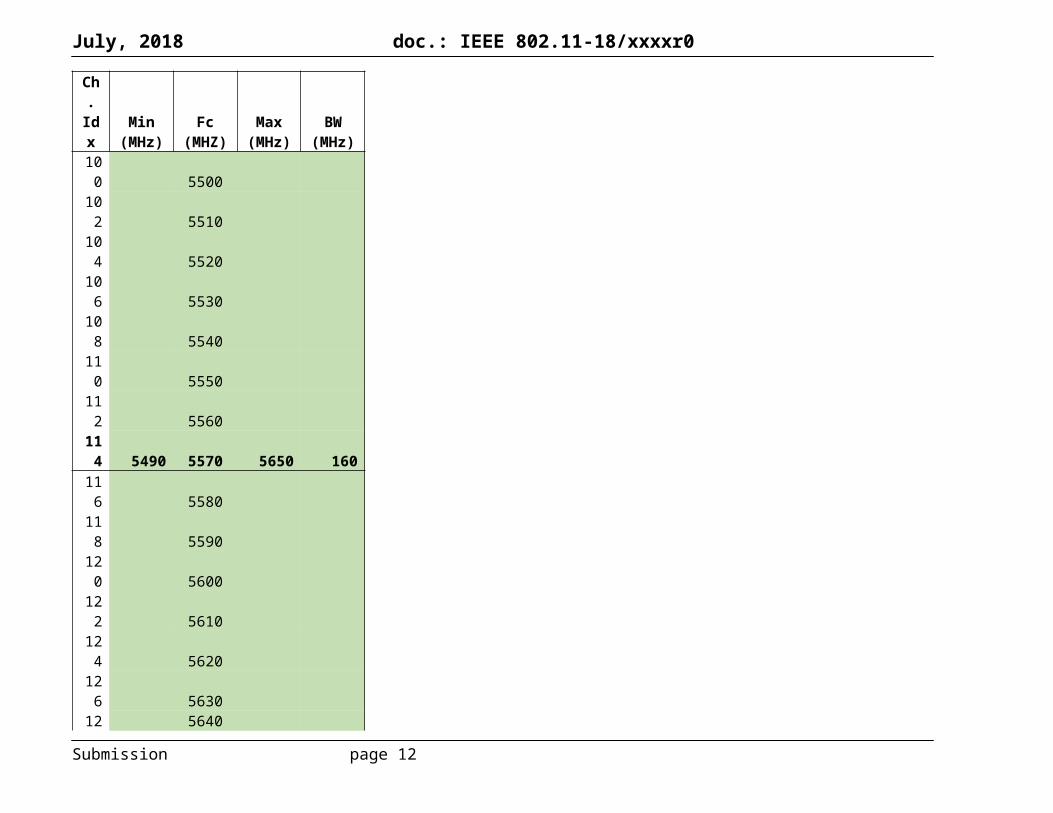
3.2.2 5 GHz Full Duplex capability shall be operational in these existing IEEE 802.11 5 GHz channels and bandwidths:
Ch. Idx
Min (MHz)
Fc (MHZ)
Max (MHz)
BW (MHz)
Ch. Idx
Min (MHz)
Fc (MHZ)
Max (MHz)
BW (MHz)
Ch. Idx
Min (MHz)
Fc (MHZ)
Max (MHz)
BW (MHz)
5170 5170 517036 5170 5180 5190 20 36 5180 36 518038 5190 38 5170 5190 5210 40 38 519040 5190 5200 5210 20 40 5200 40 520042 5210 42 5210 42 5170 5210 5250 8044 5210 5220 5230 20 44 5220 44 522046 5230 46 5210 5230 5250 40 46 523048 5230 5240 5250 20 48 5240 48 524050 5250 50 5250 50 525052 5250 5260 5270 20 52 5260 52 526054 5270 54 5250 5270 5290 40 54 527056 5270 5280 5290 20 56 5280 56 528058 5290 58 5290 58 5250 5290 5330 8060 5290 5300 5310 20 60 5300 60 530062 5310 62 5290 5310 5330 40 62 531064 5310 5320 5330 20 64 5320 64 532066 5330 5330 66 533098 5490 98 5490 98 5490
100 5490 5500 5510 20100 5500 100 5500
102 551010
2 5490 5510 5530 40 102 5510
104 5510 5520 5530 20104 5520 104 5520
106 5530106 5530 106 5490 5530 5570 80
108 5530 5540 5550 20108 5540 108 5540
110 5550 11 5530 5550 5570 40 110 5550
Submission page 7

July, 2018 doc.: IEEE 802.11-18/xxxxr0
Ch. Idx
Min (MHz)
Fc (MHZ)
Max (MHz)
BW (MHz)
Ch. Idx
Min (MHz)
Fc (MHZ)
Max (MHz)
BW (MHz)
Ch. Idx
Min (MHz)
Fc (MHZ)
Max (MHz)
BW (MHz)
0
112 5550 5560 5570 20112 5560 112 5560
114 5570114 5570 114 5570
116 5570 5580 5590 20116 5580 116 5580
118 559011
8 5570 5590 5610 40 118 5590
120 5590 5600 5610 20120 5600 120 5600
122 5610122 5610 122 5570 5610 5650 80
124 5610 5620 5630 20124 5620 124 5620
126 563012
6 5610 5630 5650 40 126 5630
128 5630 5640 5650 20128 5640 128 5640
130 5650130 5650 130 5650
132 5650 5660 5670 20132 5660 132 5660
134 567013
4 5650 5670 5690 40 134 5670
136 5670 5680 5690 20136 5680 136 5680
138 5690138 5690 138 5650 5690 5730 80
140 5690 5700 5710 20140 5700 140 5700
142 571014
2 5690 5710 5730 40 142 5710144 5710 5720 5730 20 14 5720 144 5720
Submission page 8

July, 2018 doc.: IEEE 802.11-18/xxxxr0
Ch. Idx
Min (MHz)
Fc (MHZ)
Max (MHz)
BW (MHz)
Ch. Idx
Min (MHz)
Fc (MHZ)
Max (MHz)
BW (MHz)
Ch. Idx
Min (MHz)
Fc (MHZ)
Max (MHz)
BW (MHz)
45730 5730 146 5730
147 5735147 5735 147 5735
149 5735 5745 5755 20149 5745 149 5745
151 575515
1 5735 5755 5775 40 151 5755
153 5755 5765 5775 20153 5765 153 5765
155 5775155 5775 155 5735 5775 5815 80
157 5775 5785 5795 20157 5785 157 5785
159 579515
9 5775 5795 5815 40 159 5795
161 5795 5805 5815 20161 5805 161 5805
163 5815163 5815 163 5815
165 5815 5825 5835 20165 5825 165 5825
5835
Ch. Idx
Min (MHz)
Fc (MHZ)
Max (MHz)
BW (MHz)
517036 518038 519040 520042 521044 522046 5230
Submission page 9

July, 2018 doc.: IEEE 802.11-18/xxxxr0
Ch. Idx
Min (MHz)
Fc (MHZ)
Max (MHz)
BW (MHz)
48 524050 5170 5250 5330 16052 526054 527056 528058 529060 530062 531064 532066 533098 5490
100 5500102 5510104 5520106 5530108 5540110 5550112 5560114 5490 5570 5650 160116 5580118 5590120 5600122 5610124 5620126 5630128 5640130 5650132 5660134 5670136 5680138 5690140 5700142 5710
Submission page 10
July, 2018 doc.: IEEE 802.11-18/xxxxr0
Ch. Idx
Min (MHz)
Fc (MHZ)
Max (MHz)
BW (MHz)
144 5720146 5650 5730 5810 160147 5735149 5745151 5755153 5765155 5775157 5785159 5795161 5805163 5815165 5825
Submission page 11
July, 2018 doc.: IEEE 802.11-18/xxxxr0
3.3 System Performance
3.3.1 Maximum Effective Throughput rate per BSS{Editor Note: Need simulation results comparing the Effective Throughput rates per unit area of WLANs without and with Full Duplex capability.
3.3.2 Reduction in Latency between FD enabled STAs and AP{Editor Note: Need empirical or simulation data to define the latency that two or more FD capable 802.11 devices can support relative to IEEE 802.11 devices that are not FD capable.}
3.3.3 Hidden node mitigation{Editor Note: Need text describing the overall improvement in performance of a BSS populated with devices that are hidden from each other.}
3.4 Receiver Requirements
3.4.1 Reflection/Echo CancellationIn a well designed full duplex communicaions system, it is possible to enable simultaneous transmission and reception of data and control packets using the same frequency carrier. Some of the design challenges that need to be addressed in such a system are:
The cancellation of reflected Tx signals, which may be greater in magnitude than the desired received signal. Figure 1 illustrates one such example of self interference due to a reflected impulse = .
Figure 1: Self Interference due to backscatter
3.4.2 Self-interference cancellationFigure 2 illustrates the locations of various parasitic self-interference mechanisms present in a full duplex transceiver that need to be mitigated:
Submission page 12

BB Tx
BB Rx
PA
LNAA
ntenna Interface
DAC
ADC
Full Duplex Transceiver
Parasitic Self-Interferers
BB Tx
BB Rx
PA
LNA
Antenna Interface
DAC
ADC
Full Duplex Transceiver
Parasitic Self-Interferers
Digital SIC
Filter
Analog SIC
Filter
July, 2018 doc.: IEEE 802.11-18/xxxxr0
Figure 2: Self Interference Mechanisms in a Full Duplex Transceiver
Figure 3 illustrates one potential architecture in which an analog self interference cancellation (SIC) Filter and a Digital SIC Filter have been added to a full duplex transceiver to mitigate the effects of the internal and external parasitic self-interferers that are present in any RF system.
Figure 3: Analog and Digital SIC Filtering
An example use case, in which two Full-dulplex capable transceivers are simultaneously transmitting to and receiving from each other, is illustrated in Figure 4. Also illustrated are the magnitudes of the Transmit and Receive signals in relationship to the interference signals measured after the Analog and Digital SIC filters in each Full-duplex transceiver. {EditorNote: Need additional text here re: magnitudes of PTx1 ,PTx2 , PRx1 , PRx2 and the magnitudes of the interference signals after each stage of filtering.}
Submission page 13

Tx1Rx1
Tx2Rx2
Prsi2
Psi2
PRx2
PTx2
Prsi1
PTx1
Psi1
PRx1
~35-55 dB
~40-50 dB
July, 2018 doc.: IEEE 802.11-18/xxxxr0
PTxi = Transmit signal power level from each transceiver “i”
PRxi = Received signal power level at each transceiver “i”
Psii = Self-interference(SI) power level within each transceiver “i”
Prsii = Residual SI level within each transceiver “i” after analog and digital BB cancellations
Figure 4: Relative Signal Strengths as measured in two Full-duplex transceivers with SIC Filtering.
Submission page 14

July, 2018 doc.: IEEE 802.11-18/xxxxr0
4.0 Technical Feasibility
4.1 Current instantiations of Full Duplex PHY functionality Table 1 lists six approaches, their affiliation and their attributes for enabling full duplex PHY behavior in a wireless networking system.
Table 1: Comparison of Full Duplex PHY ApproachesApproach 1 Approach 2 Approach 3 Approach 4 Approach 5 Approach 6
Antenna Separation
Meta-materials
based circulator
Antenna Polarization
Delay and Subtract Photonics
Hybrid RF/ Photonic/
Digital Baseband
Bandwidth 5MHz 1MHz 20MHz 20/40MHz 10MHz 800MHz
DriftTolerance Low High Low Moderate Moderate High
Scatter Tolerance No No No No No Yes
Environ-ment Fluctuation
Intolerant Intolerant Intolerant Intolerant Intolerant Tolerant
MIMOcapability Limited Limited Yes Yes Limited Yes
Form Factor
Antenna spacing Small Small Small Small Chip-scale
4.2 Current simulations of Full Duplex MAC functionality {EditorNote: Need text and table summarizing current FD MAC approaches.}
Submission page 15

July, 2018 doc.: IEEE 802.11-18/xxxxr0
4.3 Real world Implementations of Full Duplex operations
4.3.1 Full Duplex DOCSIS 3.1-FDXDOCSIS 3.1 R-PHY and DOCSIS 3.1-FDX provide yet another example of a wired protocol that borrows heavily from the wireless communications domain (e.g.11n-OFDM and 11ax OFDMA). Both DOCSIS 3.1 documents define the use of a full duplex protocol between cable modems (CM) and cable modem termination systems (CMTS) in a hybrid fiber/coax (HFC) network as illustrated in Figure 5.
Figure 5: Example Cable Network based upon DOCSIS 3.1-FDX
The goals of this specification are to: Increase the capacity (i.e. total available bandwidth) of the current HFC network infrastructure
without replacing existing coax to-the-home/buisness with fiber-to-the-home/business Provide backwards compatibility for CMTSs and CMSs based upon earlier versions of DOCSIS
specifications (e.g. CMTSs: 3.0, 2.0, and 1.1; CMSs:3.1, 3.0). For instance, continued support for the 16-QAM, 64-QAM, 128-QAM and 256-QAM downstream modulation schemes and the QPSK, 8-QAM, 16-QAM, 32-QAM and 64-QAM upstream modulation schemes in DOCSIS 3.0 are mandatory and required.
Improve the scalability of hybrid-fiber-coax (HFC) network infrastructure via o higher modulation schemes in both the downstream and upstream data flows as defined
in DOCSIS 3.1 R-PHY: For example, the addition of 512-QAM, 1024-QAM, 2048-QAM, and 4096-QAM are new, mandatory modulation schemes that are unique to DOCSIS 3.1 R-PHY and are not present in earlier versions of DOCSIS. In addition, DOCSIS 3.1 R-PHY defines these two new optional modulations 8192-QAM and 16384-QAM
o new spectrum usage options that increase the amount of available bandwidth, while at the same time maintaining backwards compatibility with earlier versions of DOCSIS.
o Improved energy efficiency.
Submission page 16

July, 2018 doc.: IEEE 802.11-18/xxxxr0
Increase bi-directional peak speeds by enabling symmetrical multi-gigabit per second data rates between the CMTS and CMs in both the downstream and upstream data flows (see Table 2). Key enabling technologies in support of this goal are robust echo cancellation, co-channel interference, adjacent channel interference and self-interference mitigation techniques.
Table 2: The Evolution of DOCSIS Downstream and Upstream Data rates
DOCSIS 1.0 DOCSIS 1.1 DOCSIS 2.0 DOCSIS 3.0 DOCSIS 3.1Full Duplex DOCSIS 3.1
Highlights
Initial cable broadband technology Added VoIP
Increased upstream data rate
Increased capacity & data rates
Continued increases in capacity and data rates
Symmetrical data flows w/ increased upstream data rates
Downstream Capacity
40 Mbps 40 Mbps 40 Mbps 1 Gbps 10 Gbps 10 Gbps
UpStream Capacity
10 Mbps 10 Mbps 30 Mbps 100 Mbps 1-2 Gbps 10 Gbps
Production Date
1997 2001 2002 2006 2013 2017
A major Multi-system Operator (MSO) is currently field testing a hybrid RF/Photonic analog frontend based upon the requirements specified in the DOCSIS 3.1-R-PHY and DOCSIS 3.1-FDX specifications. Key test items of this field test system, as illustrated in Figure 5, are support for:
Independentlly configurable downstream OFDM channels in which each channel may occupy a spectrum of up to 192 MHz with either 7680, 25 kHz subcarriers or 3840, 50 kHz subcarriers encompassing the frequency range between 108MHz and 684MHz (e.g. three 192 MHz OFDM channels);
Independently configurable upstream OFDMA channels in which each channel may occupy a spectrum of up to 95 MHz with either 3800, 25 kHz subcarriers or 1920, 50 kHz subcarriers encompassing the frequency range between 108 MHz and 684 MHz (e.g. six 95 MHz OFDMA channels).
Full duplex functionality between the CMs and CMTS, which is dependent upon the implementation of effective echo cancellation techniques to mitigate
o Adjacent Leakage-interference (ALI)o Adjacent Channel Interference (ACI)o Co-Channel Interference (CCI)
Backwards compatibility with CMs and CMTSs based upon earlier versions of DOCSIS.
Preliminary results from this field test are indicating that the Hybrid RF/Photonics analog frontend is meeting/exceeding the DOCSIS 3.1-R-PHY requirements for
Echo cancellation at each CM of at least 35 dBm, which is effectively mitigating the effects of o Adjacent Leakage-interference (ALI) o Adjacent Channel Interference (ACI)o Co-Channel Interference (CCI)
Submission page 17

July, 2018 doc.: IEEE 802.11-18/xxxxr0
8.0 Economic Feasibility Over the past two-plus decades, each IEEE Wi-Fi group that proposed an addition to the IEEE 802 LMSC standard provided evidence for the economic feasibility of their proposal. Evidence such as: balanced costs, known cost factors, installation costs, operational costs and estimated market size. In keeping with that tradition, the FD-TIG provides its perspective for each of these items:
a) Balanced costs (infrastructure versus attached stations)While there will be an initial small cost increment for each Full Duplex enabled access point, infrastructure utilization will be increased significantly by the addition of Full Duplex, which will enable each access point to handle more client STAs and thereby either reducing or removing the need to add and install more access points. This savings far outweighs the added cost to purchase and install new access points. For user devices, there will similarly be a small cost increment that will be no different than that encountered during a typical upgrade cycle with performance enhancements such as from 802.11n to 802.11ac or 802.11ac to 802.11ax. Depending upon the implementation, there can also be some component savings (e.g. removal of some filters/diplexers), thus offsetting the total cost when adding full duplex capability.
b) Known cost factorsSupport of the proposed standard will likely require a manufacturer to develop a modified radio, modem and firmware. This is similar in principle to the transition between IEEE 802.11n and IEEE 802.11ac as well as in previous iterations of IEEE 802.11 enhancements. By utilizing existing high-volume IC wafer, packaging, and testing facilities, devices that implement Full Duplex capable PHYs are expected to be of similar cost to current front end/ filter solutions.
c) Consideration of installation costsSince Full Duplex AP_s and STA_s are required to be backwards compatible with earlier versions of installed dot_11 devices, the installation of Full Duplex enabled AP_s and STA_s will follow a ramp function instead of a step function thereby minimizing the cost of installation.
d) Consideration of operational costs (e.g. energy consumption)Devices that implement Full Duplex are expected to require similar physical and electrical connections to existing front end and standard RFIC devices. Power consumption and thermal requirements are also expected to be similar to standard RFIC / filter solutions.
e) Market size: The market size for Full Duplex enabled Wi-Fi chipsets is expected to be 500M units in 2021 and 800M units in 2022, which equates to 20% of the combined 802.11ac and 802.11ax market in 2021 and 30% of the combined market in 2022. These market projections are derived from a WFA sponsored ABI forecast for the volume of Wi-Fi chipsets to be delivered as illustrated in Figure 6. In addition, it is assumed that pre-standard Infrastructure solutions could be available before completion of the standard to help drive market learning, uptake and cost reduction.
Submission page 18

July, 2018 doc.: IEEE 802.11-18/xxxxr0
Figure 6: Projected Wi-Fi chipset shipments
Submission page 19

July, 2018 doc.: IEEE 802.11-18/xxxxr0
9.0 Recommendation(s) EditorNote: need text here.}
Submission page 20

July, 2018 doc.: IEEE 802.11-18/xxxxr0
References:
[1] Ref 1[2] Ref 2[3] Ref 3
Submission page 21