doc 8.2, ver.1.0 alma cycle 8 2021 proposer’s guide
TRANSCRIPT

ALMA, an international astronomy facility, is a partnership of ESO (representing its member states), NSF (USA) and NINS (Japan), together with NRC (Canada), MOST and ASIAA (Taiwan), and KASI (Republic of Korea), in cooperation with the
Republic of Chile. The Joint ALMA Observatory is operated by ESO, AUI/NRAO and NAOJ.
ALMA Cycle 8 2021 Proposer’s Guide
Doc 8.2, ver.1.0 | March 2021
For further information or to comment on this document, please contact your regional Helpdesk through the ALMA User Portal at www.almascience.org. Helpdesk tickets will be directed to the appropriate ALMA Regional Center at ESO, NAOJ or NRAO.
Version Date Editors
1.0 11 March 2021 James Braatz, Andy Biggs, Patricio Sanhueza, Andrea Corvillon
In publications, please refer to this document as: J. Braatz et al. 2021, ALMA Cycle 8 2021 Proposer’s Guide, ALMA Doc. 8.2 v1.0

1
Table of Contents
1 What’s new in Cycle 8 2021 ...................................................................................................... 4
1.1 Technical and observing capabilities ......................................................................................... 4
1.2 Proposal format, composition, and review ............................................................................... 5 1.2.1 Dual-anonymous review............................................................................................................................... 5 1.2.2 Distributed peer review................................................................................................................................ 5 1.2.3 Large Programs proposal format and management plan ............................................................................ 5
1.3 Observing Tool features ........................................................................................................... 6
1.4 Prioritizing larger projects ........................................................................................................ 6
1.5 Stand-alone ACA Supplemental Call for Proposals ..................................................................... 6
2 ALMA overview ........................................................................................................................ 7
2.1 The ALMA partnership ............................................................................................................. 7
2.2 The ALMA telescope ................................................................................................................ 7
2.3 The Joint ALMA Observatory and the ALMA Regional Centers ................................................... 8
2.4 The ALMA Science Portal .......................................................................................................... 8
2.5 ALMA proposal eligibility ......................................................................................................... 9
3 Proposal types ........................................................................................................................ 10
3.1 Regular proposals .................................................................................................................. 10
3.2 Target of Opportunity proposals............................................................................................. 10
3.3 Large Programs ...................................................................................................................... 11
3.4 mm-VLBI and Phased Array proposals .................................................................................... 11
3.5 Director’s Discretionary Time proposals ................................................................................. 12
4 Proposal planning................................................................................................................... 12
4.1 Time available in Cycle 8 2021 ................................................................................................ 12
4.2 Summary of capabilities offered in Cycle 8 2021 ..................................................................... 13
4.3 Scheduling considerations ...................................................................................................... 13 4.3.1 Weather...................................................................................................................................................... 14 4.3.2 Angular resolution ...................................................................................................................................... 16 4.3.3 Configuration schedule for the 12-m Array ................................................................................................ 16 4.3.4 Observing pressure..................................................................................................................................... 19
4.4 Duplicate observations and resubmissions ............................................................................. 20 4.4.1 Checking for duplications ........................................................................................................................... 20 4.4.2 Resubmission of an unfinished proposal .................................................................................................... 21
4.5 Estimated observing time ....................................................................................................... 21
4.6 Supporting tools and documentation ..................................................................................... 23 4.6.1 The Observing Tool documentation ........................................................................................................... 23
2
4.6.2 Additional proposal preparation tools ....................................................................................................... 23 4.6.3 The ALMA Regional Center guides ............................................................................................................. 24 4.6.4 Supplemental documentation .................................................................................................................... 24
4.7 The ALMA Helpdesk ............................................................................................................... 25
5 Proposal preparation and submission ..................................................................................... 25
5.1 Proposal format ..................................................................................................................... 25
5.2 Dual-Anonymous proposal review .......................................................................................... 26
5.3 Preparing the Scientific Justification ....................................................................................... 26 5.3.1 Page limits and fonts .................................................................................................................................. 26 5.3.2 Science case ................................................................................................................................................ 27 5.3.3 Figures, tables, and references .................................................................................................................. 27
5.4 Preparing the Technical Justification....................................................................................... 27
5.5 Proposal validation, submission and withdrawal .................................................................... 28 5.5.1 Proposal updates ........................................................................................................................................ 28
5.6 Proposal evaluation and selection .......................................................................................... 29 5.6.1 Peer review ................................................................................................................................................. 29 5.6.2 Evaluation criteria ...................................................................................................................................... 30 5.6.3 Proposal selection ...................................................................................................................................... 30
5.7 Proposal confidentiality ......................................................................................................... 31
6 Post-proposal activities .......................................................................................................... 31
6.1 Observations preparation and submission: Phase 2 ................................................................ 31
6.2 Changes to submitted programs ............................................................................................. 32
6.3 Data processing and data delivery .......................................................................................... 32
6.4 Opportunities for public promotion of ALMA .......................................................................... 33
Appendix A ALMA Cycle 8 2021 Capabilities ........................................................................... 34
Appendix B Technical Justification guidelines ......................................................................... 50
Appendix C Acronyms and abbreviations ............................................................................... 57
Appendix D Science categories and keywords ........................................................................ 59
3
Cycle 8 2021 Call for Proposals The ALMA Director, on behalf of the Joint ALMA Observatory (JAO) and the partner organizations in East Asia, Europe, and North America, is pleased to announce the ALMA Cycle 8 2021 Call for Proposals (CfP) for scientific observations to be scheduled from October 2021 to September 2022. Following the postponement of Cycle 8 because of the COVID-19 pandemic, the next cycle of observations is being referred to as “Cycle 8 2021”. This document has newly updated information over the Cycle 8 Proposer’s Guide issued in March 2020. As the global response to the pandemic continues to evolve, we encourage interested parties to follow the ALMA Science Portal for the latest information. The JAO anticipates allocating 4300 hours on the 12-m Array and 3000 hours1 on the Atacama Compact Array (ACA), also known as the Morita Array, for successful proposals from the Main Call in Cycle 8 2021. The ACA allocation includes 3000 hours each on the 7-m Array and the Total Power (TP) Array. Proposals must be prepared and submitted using the ALMA Observing Tool (OT), which is available for download from the ALMA Science Portal (www.almascience.org). New for this Cycle, a dual-anonymous process is being implemented for proposal reviews. While proposers will still enter their names and affiliations in the OT, their identities will be concealed from the science reviewers. It will be the responsibility of the investigators to write their proposals such that anonymity is preserved. In addition, ALMA is using distributed peer review for proposals requesting less than 25 hours on the 12-m Array and for ACA stand-alone proposals requesting less than 150 hours on the 7-m Array. The PI for such proposals or a designee from the list of investigators will review and rank 10 submitted proposals from this Call, for each proposal submitted. ALMA Cycle 8 2021 proposal submission will open at 15:00 UT on Wednesday, 17 March 2021. The Cycle 8 2021 proposal submission deadline is 15:00 UT on Wednesday, 21 April 2021. These and other important milestones for Cycle 8 2021 are summarized in Table 1. PIs are responsible for submitting their proposals successfully by the deadline, and are strongly advised to submit proposals early. Cycle 8 2021 will include a Supplemental CfP for stand-alone ACA observations with the Cycle 8 2021 technical capabilities specified in this document. The observations will be scheduled from January 2022 to September 2022 (Section 1.5). The Supplemental Call will have some differences compared to the Main Call, including the priority of the observations. Details will be released with the Supplemental CfP. In what follows, this document refers to the characteristics of the Cycle 8 2021 Main CfP unless specifically indicated otherwise. ALMA provides continuum and spectral-line capabilities for wavelengths from 0.32 mm to 3.6 mm, and angular resolutions from 0.012” to 3.4” on the 12-m Array. In Cycle 8 2021, the most extended configuration for the 12-m Array will be C-8, providing angular resolutions as fine as 0.028”. The more extended C-9 and C-10 configurations will next be available in Cycle 9. Cycle 8 2021 will bring to ALMA several new observational capabilities, including Solar observations in Band 5, stand-alone 7-m Array observations in Bands 9 and 10, mosaicking of continuum linear polarization observations in Bands 3 to 7 with the 12-m Array, single-field polarization observations with the
1 The JAO anticipates allocating additional time, the amount to be determined, through the ACA Supplemental Call (Section 1.5).
4
stand-alone 7-m Array, spectral scans with the 7-m Array, VLBI observations of faint science targets using the Passive Phasing mode, and observations using the 12-m Array operating as a single dish for pulsar science. This Proposer’s Guide provides an overview of significant changes since Cycle 7 made in both the technical capabilities and observing strategies (Section 1), an overview of the ALMA organization (Section 2), the types of proposals offered in Cycle 8 2021 (Section 3), information on proposal planning (Section 4) and submission (Section 5) and post-proposal activities (Section 6), an overview of the offered technical capabilities (Appendix A), and guidelines for writing a Technical Justification (Appendix B).
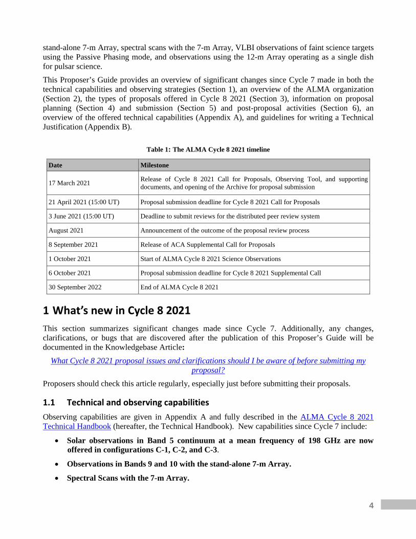
Table 1: The ALMA Cycle 8 2021 timeline
Date Milestone
17 March 2021 Release of Cycle 8 2021 Call for Proposals, Observing Tool, and supporting documents, and opening of the Archive for proposal submission
21 April 2021 (15:00 UT) Proposal submission deadline for Cycle 8 2021 Call for Proposals
3 June 2021 (15:00 UT) Deadline to submit reviews for the distributed peer review system
August 2021 Announcement of the outcome of the proposal review process
8 September 2021 Release of ACA Supplemental Call for Proposals
1 October 2021 Start of ALMA Cycle 8 2021 Science Observations
6 October 2021 Proposal submission deadline for Cycle 8 2021 Supplemental Call
30 September 2022 End of ALMA Cycle 8 2021
1 What’s new in Cycle 8 2021 This section summarizes significant changes made since Cycle 7. Additionally, any changes, clarifications, or bugs that are discovered after the publication of this Proposer’s Guide will be documented in the Knowledgebase Article:
What Cycle 8 2021 proposal issues and clarifications should I be aware of before submitting my proposal?
Proposers should check this article regularly, especially just before submitting their proposals.
1.1 Technical and observing capabilities Observing capabilities are given in Appendix A and fully described in the ALMA Cycle 8 2021 Technical Handbook (hereafter, the Technical Handbook). New capabilities since Cycle 7 include:
• Solar observations in Band 5 continuum at a mean frequency of 198 GHz are now offered in configurations C-1, C-2, and C-3.
• Observations in Bands 9 and 10 with the stand-alone 7-m Array.
• Spectral Scans with the 7-m Array.
5
• Mosaics for continuum linear polarization observations in Bands 3 to 7 with the 12-m Array. Field setups can be defined using custom mosaics or rectangular areas. The mosaic is subject to a maximum of 150 pointings per scheduling block.
• Stand-alone 7-m Array polarization observations. Single-field interferometric linear polarization observations with the 7-m Array are available in Bands 3 to 7 with any frequency setup. The measurements are accurate for the central one third of the FWHM beam. Multiple pointings are permitted, however mosaics are not supported at this time. There will be a maximum of 75 hours offered for this mode.
• VLBI observations of faint science targets. Observations of targets with correlated flux densities <500 mJy are now permitted by using the Passive Phasing mode, where it is recommended to have a bright calibrator within 6° or 3° of the science target in Band 3 or 6, respectively.
• Observations of pulsars using the 12-m Array as a single dish. For VLBI, ALMA uses special hardware that coherently sums the signals from each antenna, effectively allowing the 12-m Array to mimic a large single dish. It is now possible to observe in this Phased Array mode in a stand-alone (non-VLBI) capacity for pulsar science.
1.2 Proposal format, composition, and review
1.2.1 Dual-anonymous review To help reduce biases, ALMA will implement a dual-anonymous review process starting in Cycle 8 2021. In a dual-anonymous review, the proposal team does not know the identity of the reviewers and the reviewers do not know the identities of the proposal team. While proposers will still enter their names and affiliations in the ALMA OT, this information will not appear on the proposal cover sheet, nor in the tools used by the reviewers. It is the responsibility of the proposers to ensure anonymity is preserved when writing their proposals. More information can be found in Section 5.2.
1.2.2 Distributed peer review ALMA is using a distributed peer review system for proposals requesting less than 25 hours on the 12-m Array and for ACA stand-alone proposals requesting less than 150 hours on the 7-m Array. For each proposal submitted, the PI or a designee from the list of investigators will review and rank 10 submitted proposals from this Call. Review assignments will be made based on the expertise of the designated reviewer as listed on their ALMA user profile. Users are strongly advised to update the specification of their expertise in the Science Portal by the proposal deadline. See Section 5.6.1 for more information on distributed peer review.
1.2.3 Large Programs proposal format and management plan Proposals for Large Programs will now consist of two parts, both submitted with the OT at the time of proposal submission. First is the main proposal itself, which is a PDF file up to 6 pages in length. The main proposal must contain (1) the Scientific Justification, (2) a description of the data products and documentation that will be provided to the community, (3) the publication plan, and (4) a discussion of the scheduling feasibility. The scheduling feasibility is necessary since it can impact the selection of targets and therefore the proposed science. The main proposal must follow the guidelines for dual-anonymous review. The second part will be a one-page PDF statement that describes the management plan. This statement is not expected to follow the dual-anonymous
6
guidelines, and indeed should include investigator names and affiliations. The management plan must include a description of the roles and responsibilities of the proposal team as well as the computing resources available to the team to process and analyze their data. Section 3.3 gives more information on Large Programs. PIs of Large Programs are also encouraged to contact their corresponding ARC or ARC node to get help with proposal preparations.
1.3 Observing Tool features For Cycle 8 2021, the Web Start installation is no longer available for the OT. It has been dropped from Java starting with version 11. Instead, a new installer has been created with a modern interface that guides the user through the steps necessary for installation. A separate installer is available for Linux, Mac OS, and Windows and it includes a self-contained distribution of Java 11. It is therefore no longer necessary for users to install Java themselves. The alternative tarball distribution remains available and this will also include Java. All new features are described in more detail in the OT documentation.
1.4 Prioritizing larger projects Following recommendations from the ALMA Science Advisory Committee (ASAC) and the ALMA International Visiting Committee (IVC), ALMA is taking further steps to encourage large, more ambitious proposal submissions. First, ALMA has removed the cap on the total amount of time that can be allotted to Large Programs as of Cycle 8 2021. However, Large Programs will still be limited to filling no more than 50% of the time in a given LST and configuration so that smaller programs will be able to compete at each configuration and LST. Second, proposals that request more than 25 hours on the 12-m Array (including Large Programs) will have priority when filling at least 10% of the available time for Grade A and B proposals. If the total amount of time for the Large Programs recommended by the APRC sum to less than 430 hours on the 12-m Array, then the highest ranked proposals requesting between 25 and 50 hours will be given next priority in building the queue.
1.5 Stand-alone ACA Supplemental Call for Proposals Cycle 8 2021 will include a Supplemental CfP for stand-alone ACA observations to be scheduled from January 2022 to September 2022. The Supplemental Call aims to maximize the scientific output of the ACA by allowing more timely science to be proposed, since it will follow the Main CfP by five months. The amount of observing time to be allocated during the ACA Supplemental Call will be determined later. The JAO anticipates releasing the Supplemental Call on 8 September 2021, with a proposal submission deadline of 15:00 UT on 6 October 2021. Proposals may request to use the 7-m Array only or the 7-m Array plus the Total Power Array. The observational capabilities for the stand-alone ACA Supplemental Call will be the same as those offered for the ACA in the Main Call (see Appendix A). Supplemental Call proposals selected for the observing queue will be given grade C observing priority, while successful proposals from the Main Call that request the ACA (either in stand-alone mode or in combination with the 12-m Array) may be given grades A, B, or C. Large Programs will not be allowed in the Supplemental Call. There will be no LST restriction on proposals at the time of submission. Any stand-alone ACA proposal rejected in the Main Call may be modified to address comments from the reviewers and submitted to the Supplemental Call.
7
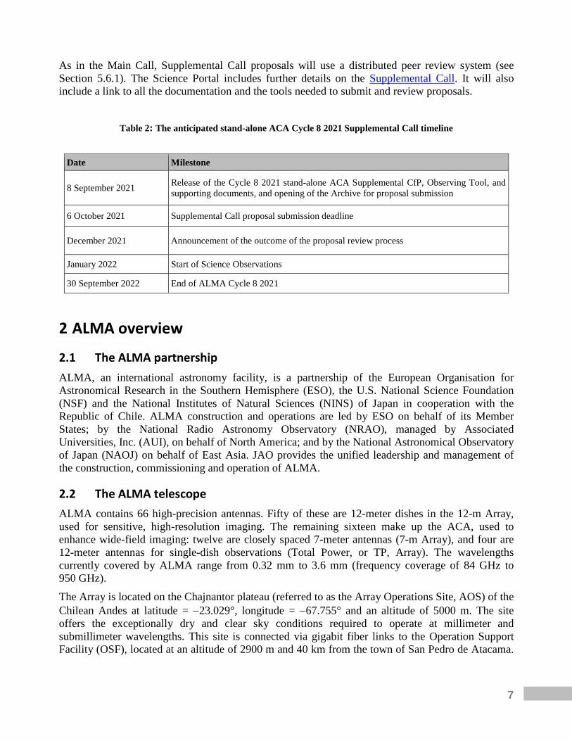
As in the Main Call, Supplemental Call proposals will use a distributed peer review system (see Section 5.6.1). The Science Portal includes further details on the Supplemental Call. It will also include a link to all the documentation and the tools needed to submit and review proposals.
Table 2: The anticipated stand-alone ACA Cycle 8 2021 Supplemental Call timeline
Date Milestone
8 September 2021 Release of the Cycle 8 2021 stand-alone ACA Supplemental CfP, Observing Tool, and supporting documents, and opening of the Archive for proposal submission
6 October 2021 Supplemental Call proposal submission deadline
December 2021 Announcement of the outcome of the proposal review process
January 2022 Start of Science Observations
30 September 2022 End of ALMA Cycle 8 2021
2 ALMA overview
2.1 The ALMA partnership ALMA, an international astronomy facility, is a partnership of the European Organisation for Astronomical Research in the Southern Hemisphere (ESO), the U.S. National Science Foundation (NSF) and the National Institutes of Natural Sciences (NINS) of Japan in cooperation with the Republic of Chile. ALMA construction and operations are led by ESO on behalf of its Member States; by the National Radio Astronomy Observatory (NRAO), managed by Associated Universities, Inc. (AUI), on behalf of North America; and by the National Astronomical Observatory of Japan (NAOJ) on behalf of East Asia. JAO provides the unified leadership and management of the construction, commissioning and operation of ALMA.
2.2 The ALMA telescope ALMA contains 66 high-precision antennas. Fifty of these are 12-meter dishes in the 12-m Array, used for sensitive, high-resolution imaging. The remaining sixteen make up the ACA, used to enhance wide-field imaging: twelve are closely spaced 7-meter antennas (7-m Array), and four are 12-meter antennas for single-dish observations (Total Power, or TP, Array). The wavelengths currently covered by ALMA range from 0.32 mm to 3.6 mm (frequency coverage of 84 GHz to 950 GHz). The Array is located on the Chajnantor plateau (referred to as the Array Operations Site, AOS) of the Chilean Andes at latitude = −23.029°, longitude = −67.755° and an altitude of 5000 m. The site offers the exceptionally dry and clear sky conditions required to operate at millimeter and submillimeter wavelengths. This site is connected via gigabit fiber links to the Operation Support Facility (OSF), located at an altitude of 2900 m and 40 km from the town of San Pedro de Atacama.

8
Science operations are conducted from the OSF and coordinated from the JAO Santiago Central Office (SCO). The Technical Handbook contains a detailed description of the ALMA technical characteristics.
2.3 The Joint ALMA Observatory and the ALMA Regional Centers The JAO is responsible for the overall leadership and management of ALMA operations in Chile. The JAO solicits proposals to observe with ALMA through Calls for Proposals and organizes the peer review of the proposals by science experts. In addition, the JAO schedules all science observations and places the data in the electronically accessible archive. The three Executives maintain the ALMA Regional Centers (ARCs) within their respective regions. The ARCs provide the interface between the ALMA Observatory and its user communities. The ARCs are responsible for user support, mainly in the areas of proposal preparation, observation preparation, acquisition of data through the Archive, data reduction, data analysis, data delivery, face-to-face visitor support and workshops, tutorials, and schools. Each ARC operates an archive that mirrors the SCO Archive. Browsing and data mining are done through the ARC mirror archives. The East Asian ARC (EA ARC) is based at the National Astronomical Observatory of Japan (NAOJ) headquarters in Tokyo. It is operated in collaboration with Academia Sinica Institute of Astronomy and Astrophysics (ASIAA) in Taiwan and Korea Astronomy and Space Science Institute (KASI) in Korea and supports the astronomical communities of Japan, Taiwan2 and the Republic of Korea. European researchers are supported by the European ARC (EU ARC), which is organized as a coordinated network of scientific support nodes distributed across Europe. The EU ARC is located at ESO Headquarters in Garching bei München (Germany), where many of the ARC activities take place. Face-to-face support and additional services are provided by seven regional nodes. The regional nodes are currently: Bonn-Cologne (Germany), Bologna (Italy), Onsala (Sweden), IRAM, Grenoble (France), Allegro, Leiden (The Netherlands), Manchester (United Kingdom) and Ondřejov (Czech Republic). The North American ARC (NA ARC) is contained within the North American ALMA Science Center (NAASC), based at NRAO headquarters in Charlottesville, VA, USA. It is operated in collaboration with the National Research Council of Canada (Canada) and Academia Sinica Institute of Astronomy and Astrophysics (Taiwan), and supports the astronomical communities of North America and Taiwan2.
2.4 The ALMA Science Portal The ALMA Science Portal (SP), accessible at http://almascience.org, is the primary access point to ALMA for science users. It provides a gateway to all ALMA resources, documents and tools relevant to users for proposal preparation, proposal assessment, project tracking, project data access and data retrieval, as well as access to the ALMA Helpdesk. From the Science Portal, anyone can:
• Register as an ALMA user.
2 Support of the Taiwanese astronomical community is shared by the EA and NA ARCs.

9
• Access ALMA user documentation and software tools, including the ALMA Sensitivity Calculator, observing simulators, and the ALMA spectral-line database (Splatalogue).
• Download the OT. • Access Helpdesk “Knowledgebase” articles, which provide answers to common questions. • Access non-proprietary data from the ALMA Archive.
In addition, registered users may:
• Manage their user profile. Here, users can specify their area of expertise, set an option to receive automatic email notifications of the progress of their observations, grant access to proprietary data for other ALMA users, and delegate the right to trigger Target of Opportunity (ToO) observations to another selected ALMA user.
• Access SnooPI, the tool for PIs, co-PIs, co-Is, and any other user designated by the PIs, to monitor the status of their scheduled observing projects.
• Submit Helpdesk tickets. • Trigger ToO observations. • Access their proprietary data through the ALMA Archive.
The Science Portal also includes links to the ARCs webpages, from which users can access regional information and specific services of each ARC, such as visitor and student programs, schools, workshops, and outreach materials and activities. Users must update their ALMA user profile, rather than registering multiple accounts, whenever there is a change in their personal information such as a new email address or a change of affiliation (see Section 2.1 of the ALMA Users’ Policies). Finally, users are encouraged to complete the “Demographics” section of their profile to help ALMA provide adequate user support.
2.5 ALMA proposal eligibility Users of any nationality or affiliation may submit an ALMA proposal. All proposals are evaluated on the basis of scientific merit by a distributed peer review system or by a panel-based proposal review system. Each proposal must have a PI who is the official contact between ALMA and the proposing team for all correspondence related to the project. Large Programs and mm-VLBI proposals may designate co-PIs, who will share the overall responsibility of conducting the proposed science. If co-PIs are identified, the requested observing time will be split among the regions (North America, Europe, East Asia, and Chile) in proportion to the affiliations of the PI and co-PIs (Section 5.6.3). Regardless of the inclusion of co-PIs, the PI has proprietary access to the ALMA data during the proprietary period, and is in charge of the delivery of the data products in the case of Large Programs, in accordance with the ALMA Users’ Policies. Any other individuals who are actively involved in any proposal may be designated as co-Is. There is no limit to the number of co-Is or co-PIs who may appear on a proposal. Additional rules apply for qualification to use the Chilean share of the time and they are described at http://www.das.uchile.cl/~alma_crc/.

10
ALMA Users’ Policies prohibit multiple submissions of the same proposal using different regional affiliations. If such proposals are detected, only the first submitted version will be considered by the reviewers.
3 Proposal types
3.1 Regular proposals Regular proposals relate to observations that can be fully specified by the proposal submission deadline and whose estimated execution time does not exceed 50 hours on the 12-m Array or 150 hours on the 7-m Array in stand-alone mode. Regular proposals may involve time-critical, multiple-epoch observations, and the monitoring of a target over a fixed time interval. Figure 1 (left panel) shows that most Cycle 7 proposals requested between 2 and 20 hours of 12-m Array time. However, the success rate of proposals was roughly constant up to 40 hours of requested 12-m Array time (Figure 1, right panel). The JAO aims to have a diverse scientific portfolio by executing a balance of programs with various sizes in terms of observing time. To encourage more ambitious programs, proposals requesting more than 25 hours on the 12-m Array will have priority when building the observation queue (see Section 1.4). No restrictions are imposed on the size of the time window specified by PIs for time-critical observations. The scheduling feasibility of any proposal will depend on the total number of constraints that are imposed (see Section 4.3). Importantly, any time constraint, as with any other type of observational constraint, must be scientifically and technically justified.
Figure 1: (Left) Number of proposals submitted as a function of the 12-m Array execution time in Cycle 7. (Right) The fraction of proposals (with 1σ confidence intervals) that are assigned priority Grade A or B as a function of the estimated 12-m Array time.
3.2 Target of Opportunity proposals Target of Opportunity (ToO) proposals should be submitted for observations that can be anticipated but whose targets and/or time of observation are not known in advance. Like Regular proposals, these proposals must be submitted by the Cycle 8 2021 proposal deadline. As for all other types of proposals, observing modes and sensitivity requests must be specified at the time of submission. In contrast, the target list may be specified at the moment of triggering the proposal. For each triggered
11
Scheduling Block (SB) the proposal should specify the number of triggers needed, what the trigger event will be, and the necessary reaction time for scheduling the observation after it is triggered. Regular proposals wrongly submitted by the PI as ToO proposals may be rejected on technical grounds. The JAO will give priority to observing ToO proposals during the time period requested by the PI after a trigger request has been submitted, provided the appropriate scheduling conditions (mainly weather and antenna configuration, see Section 4.3) are met and the observations do not conflict with critical engineering and development activities or critical observations with a higher grade. For requests of reaction times under 24 hours, the Observatory recommends that PIs give notice as early as possible about target coordinates or redshift for preparation of the Phase 2 SBs. PIs will trigger observations from accepted ToO proposals through the Project Trigger Submission Page available at the ALMA Helpdesk. Further instructions on how to trigger a project are available at the ToO Activation page on the Science Portal. Upon receiving a trigger, the Observatory will communicate with the PI through the Helpdesk ticket to clarify any remaining issues.
3.3 Large Programs Large Programs are proposals with an estimated execution time of greater than 50 hours on the 12-m Array (with or without accompanying ACA time) or 150 hours on the 7-m Array in stand-alone mode. Large Programs should not involve time-critical or ToO observations, and may not include full polarization measurements, Solar observations, VLBI, Phased Array mode, or Astrometric observations (see Section A.9.5 for more information on Astrometric observations). A Large Program proposal should address strategic scientific issues that will lead to a major advance or breakthrough in the field, be a coherent science project, not reproducible by a combination of Regular proposals, lead to high level archival data products, and contain a solid management plan ensuring an efficient utilization of the data, including analysis and organization of the efforts. Consequently, the proposal team should not submit one or more Regular proposals for the same observations in parallel with a Large Program. In such a case, the Regular proposals would not be considered. Further details are available in the Knowledgebase article “Are there policies specific to Large Programs?”. The program teams are expected to deliver their proposed data products and documentation describing the data products to ALMA within one year of the final delivery of calibrated products. The data products and documents will be made available to the community at large. The Science Portal contains a document describing the standards for Large Program enhanced products to ensure their proper ingestion into the ALMA Science Archive. Proposals requesting more than 25 hours on the 12-m Array, including Large Programs, will have priority to fill at least 10% of the observing queue (see Section 1.4). However, Large Programs will not be allowed to exceed 50% of the available time for a given LST range in any of the Cycle 8 2021 configurations. Section 4.3.3 shows the configuration schedule and time available per configuration.
3.4 mm-VLBI and Phased Array proposals ALMA VLBI proposals are made in concert with either the Global Millimeter VLBI Array (GMVA) at 3 mm (Band 3) or the Event Horizon Telescope (EHT) network at 1.3 mm (Band 6). For 3 mm VLBI observations, PIs must have submitted a proposal to the GMVA network by 1 February 2021 in addition to their ALMA VLBI proposal.
12
ALMA-specific VLBI considerations are given in Section A.12 of this document. Further details on submitting 3 mm VLBI proposals to the GMVA are available from the GMVA website. Further details on submitting 1.3 mm VLBI proposals to the EHT are available from the EHT website. Proposals should include a quantitative justification describing why ALMA is essential for the project. VLBI observations cannot be included in Large Programs. VLBI observations that include ALMA will likely occur in March/April 2022. Given that the outcome of VLBI Cycle 7 proposals may not be known before the ALMA Cycle 8 2021 proposal deadline, PIs of such proposals may wish to resubmit their proposals in Cycle 8 2021 in case the Cycle 7 observations are unsuccessful. No resubmission to the GMVA network call for proposals is needed in such cases. Further details on the handling of resubmitted proposals are available in Section 4.4.2. Pulsar observing capabilities using ALMA’s Phased Array observing mode are described in Section A.13 of this document. A maximum of 50 hours of Cycle 8 2021 time will be available for Phased Array mode observations. These observations will take place during the VLBI time blocks anticipated to be in March/April 2022. Phased Array observations cannot be included in Large Programs.
3.5 Director’s Discretionary Time proposals Director’s Discretionary Time (DDT) proposals may be submitted at any time. To qualify for DDT, proposals must fulfill the conditions specified at the Science Portal. Capabilities, time tolerance restrictions, and science assessment will be based on the same criteria as for Regular and ToO proposals, and DDT proposals must comply with the anonymization rules as well. VLBI and Phased Array proposals are eligible for DDT. DDT proposals will be considered for approval by the ALMA Director based on the advice of a Standing Review Committee, with members from the JAO and the four regions, appointed by the Executive Directors and the ALMA Director. In exceptional cases, the ALMA Director may approve DDT proposals that would benefit from a very rapid response, and inform the Standing Committee and science operations team of this decision within 24 hours. Further DDT policies are described in the ALMA Users’ Policies.
4 Proposal planning
4.1 Time available in Cycle 8 2021 Cycle 8 2021 will span 12 months, starting in 2021 October and finishing in 2022 September. The JAO anticipates having 4300 hours on the 12-m Array and at least 3000 hours3 on both the 7-m Array and the TP Array available for successful PI programs, including DDT proposals as well as Cycle 7 grade A proposals that are carried over. VLBI and DDT are limited to a maximum of 5% each of the available time (Sections 3.4 and 3.5). There is no overall cap on Large Programs, but they may fill no more than 50% of the time at a given LST and configuration (Section 3.3).
3 Additional time, the specific amount to be determined later, will be offered in the stand-alone ACA Supplemental Call.

13
4.2 Summary of capabilities offered in Cycle 8 2021 The Cycle 8 2021 capabilities are described in Appendix A. In summary, they are: Number of antennas
• At least forty-three antennas in the 12-m Array. • At least ten 7-m antennas (for short baselines) and three 12-m antennas (for single-dish maps)
in the ACA. Receiver bands
• Receiver Bands 3, 4, 5, 6, 7, 8, 9, and 10 (wavelengths of about 3.0, 2.0, 1.6, 1.3, 0.85, 0.65, 0.45, and 0.35 mm, respectively).
12-m Array Configurations • Cycle 8 2021 includes configurations C-1 through C-8. Configurations C-9 and C-10 will
next be available in Cycle 9. • Maximum baselines between 0.16 km and 8.5 km depending on array configuration and
subject to the following restrictions: o The maximum possible baseline for Bands 8, 9 and 10 is 3.6 km. o The maximum possible baseline for Bands 3, 4, 5, 6 and 7 is 8.5 km.
Configurations with maximum baselines equal to or longer than 3.6 km (C-7 to C-10) are considered “long-baseline configurations”. Observations in these configurations include more frequent calibration compared to more compact configurations to ensure the quality of the observations. Files containing notional antenna configurations for the 12-m and 7-m Arrays suitable for Common Astronomy Software Applications (CASA) simulations are available from the ALMA Science Portal.
Spectral-line, continuum, and mosaic observations • Spectral-line and continuum observations with the 12-m Array and the 7-m Array in all
bands. • Single-field interferometry (all bands) and mosaics (Bands 3 to 9) with the 12-m Array and
the 7-m Array. • Single-dish spectral-line observations in Bands 3 to 8.
Polarization • Single-pointing, on-axis, full linear and circular polarization for both continuum and full
spectral resolution observations in Bands 3 to 7 on the 12-m Array. The field of view of linear and circular polarization observations is limited to the inner one third and the inner one tenth of the primary beam, respectively.
• Single-pointing, on-axis linear polarization on the stand-alone 7-m Array in Bands 3 to 7. The field of view is limited to the inner one third of the primary beam. A maximum of 75 hours will be offered for this mode.
• Mosaics for continuum linear polarization observations for the 12-m Array in Bands 3 to 7. Such mosaics are subject to a maximum of 150 pointings.
4.3 Scheduling considerations Apart from time-constrained observations, various aspects of a proposed observation such as weather conditions or requested angular resolution and Largest Angular Structure (LAS) may affect
14
when an observation is scheduled. This section describes the most important scheduling considerations that investigators should be aware of when preparing their ALMA proposal.
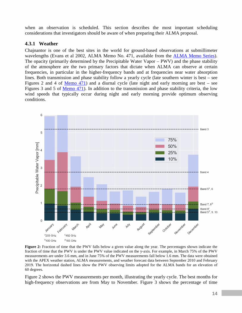
4.3.1 Weather Chajnantor is one of the best sites in the world for ground-based observations at submillimeter wavelengths (Evans et al 2002, ALMA Memo No. 471, available from the ALMA Memo Series). The opacity (primarily determined by the Precipitable Water Vapor – PWV) and the phase stability of the atmosphere are the two primary factors that dictate when ALMA can observe at certain frequencies, in particular in the higher-frequency bands and at frequencies near water absorption lines. Both transmission and phase stability follow a yearly cycle (late southern winter is best – see Figures 2 and 4 of Memo 471) and a diurnal cycle (late night and early morning are best – see Figures 3 and 5 of Memo 471). In addition to the transmission and phase stability criteria, the low wind speeds that typically occur during night and early morning provide optimum observing conditions.
Figure 2: Fraction of time that the PWV falls below a given value along the year. The percentages shown indicate the fraction of time that the PWV is under the PWV value indicated on the y-axis. For example, in March 75% of the PWV measurements are under 3.6 mm, and in June 75% of the PWV measurements fall below 1.6 mm. The data were obtained with the APEX weather station, ALMA measurements, and weather forecast data between September 2010 and February 2019. The horizontal dashed lines show the PWV observing limits adopted for the ALMA bands for an elevation of 60 degrees.
Figure 2 shows the PWV measurements per month, illustrating the yearly cycle. The best months for high-frequency observations are from May to November. Figure 3 shows the percentage of time
15
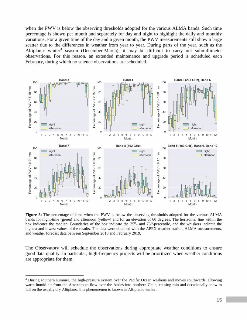
when the PWV is below the observing thresholds adopted for the various ALMA bands. Such time percentage is shown per month and separately for day and night to highlight the daily and monthly variations. For a given time of the day and a given month, the PWV measurements still show a large scatter due to the differences in weather from year to year. During parts of the year, such as the Altiplanic winter4 season (December-March), it may be difficult to carry out submillimeter observations. For this reason, an extended maintenance and upgrade period is scheduled each February, during which no science observations are scheduled.
Figure 3: The percentage of time when the PWV is below the observing thresholds adopted for the various ALMA bands for night-time (green) and afternoon (yellow) and for an elevation of 60 degrees. The horizontal line within the box indicates the median. Boundaries of the box indicate the 25th- and 75th-percentile, and the whiskers indicate the highest and lowest values of the results. The data were obtained with the APEX weather station, ALMA measurements, and weather forecast data between September 2010 and February 2019.
The Observatory will schedule the observations during appropriate weather conditions to ensure good data quality. In particular, high-frequency projects will be prioritized when weather conditions are appropriate for them.
4 During southern summer, the high-pressure system over the Pacific Ocean weakens and moves southwards, allowing warm humid air from the Amazons to flow over the Andes into northern Chile, causing rain and occasionally snow to fall on the usually dry Altiplano: this phenomenon is known as Altiplanic winter.
16
4.3.2 Angular resolution PIs can enter a single value or a range when specifying acceptable angular resolutions for a given Science Goal (SG) in the OT (see Section 4.5 for more on Science Goals). Whenever feasible, PIs are encouraged to enter a range spanning more than one configuration. Such a choice will improve chances for having the SB observed, especially for SBs with an intrinsically low probability of execution due to, for example, weather or time constraints. In practice, the OT will assign to a given SB any number of configurations that fulfill the angular resolution range requested by the PI. For scheduling feasibility and Quality Assurance (QA) purposes, the following will also be considered:
• If the PI selects a single value for the angular resolution or a range narrower than 20% around its center value, a range of ±20% around the single or center value specified will be enforced.
• If the requested range (after applying the previous rule) does not include the resolution of at least one of the notional configurations, the range will be extended to include the resolution of the closest notional configuration.
• If the requested range includes both long-baseline and more compact configurations, only the latter will be considered. An exception is constituted by ToO observations that can be triggered in any configuration if the angular resolution requested by the PI is “any” (see Section 3.2).
The final range of angular resolutions (i.e., after all the above factors have been considered) that the Observatory will use, and the corresponding set of configurations, are displayed in the Phase 2 SBs in the OT so that they can be reviewed by PIs. Users should note that the synthesized beam shape can be elongated, in particular for sources of high or very low declinations (see Section 7.4 of the Technical Handbook for details). For reference, the OT will show the expected 2-D beam dimensions and maximum axial ratio based on observations near transit for a given source. Observations away from transit will result in a higher axial ratio than that shown. PIs aiming to obtain a specific surface brightness sensitivity may enter their request in temperature units. In this case, if a range of acceptable resolutions is specified by the PI, the time estimate will be determined by the time needed to achieve the surface brightness sensitivity requested at the resolution of the most extended configuration fitting the provided range (i.e., highest resolution). ALMA QA processes are defined in terms of resolution and flux density sensitivity, so the actual surface brightness sensitivity delivered will depend on the resolution achieved by the observations (see Chapter 11 of the Technical Handbook for more details). Thus, a temperature sensitivity worse than requested could be obtained if the resolution achieved in the delivered images is still within the requested range but higher than that of the most extended configuration assigned to that SB.
4.3.3 Configuration schedule for the 12-m Array The ALMA 12-m Array will be configured in 8 different configurations during Cycle 8 2021. Note that the longest baseline configurations, C-9 and C-10, will not be available in Cycle 8 2021. While each configuration contains fifty 12-m antennas, only a subset of the 50 antennas will be available for most observations due to maintenance activities, calibration observations, and testing new capabilities. These operational factors impact the actual configuration achieved for a given observation, so the configurations used for simulations and planning are referred to here as “notional configurations.” The OT assumes 43 antennas are available when calculating the time estimates and image characteristics based on these configurations. Configurations are now denoted
17
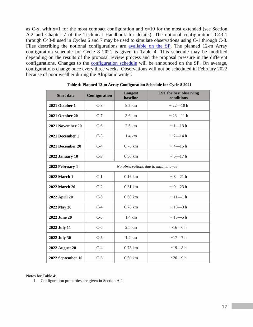
as C-x, with x=1 for the most compact configuration and x=10 for the most extended (see Section A.2 and Chapter 7 of the Technical Handbook for details). The notional configurations C43-1 through C43-8 used in Cycles 6 and 7 may be used to simulate observations using C-1 through C-8. Files describing the notional configurations are available on the SP. The planned 12-m Array configuration schedule for Cycle 8 2021 is given in Table 4. This schedule may be modified depending on the results of the proposal review process and the proposal pressure in the different configurations. Changes to the configuration schedule will be announced on the SP. On average, configurations change once every three weeks. Observations will not be scheduled in February 2022 because of poor weather during the Altiplanic winter.
Table 4: Planned 12-m Array Configuration Schedule for Cycle 8 2021
Start date Configuration Longest baseline
LST for best observing conditions
2021 October 1 C-8 8.5 km ~ 22—10 h
2021 October 20 C-7 3.6 km ~ 23—11 h
2021 November 20 C-6 2.5 km ~ 1—13 h
2021 December 1 C-5 1.4 km ~ 2—14 h
2021 December 20 C-4 0.78 km ~ 4—15 h
2022 January 10 C-3 0.50 km ~ 5—17 h
2022 February 1 No observations due to maintenance
2022 March 1 C-1 0.16 km ~ 8—21 h
2022 March 20 C-2 0.31 km ~ 9—23 h
2022 April 20 C-3 0.50 km ~ 11—1 h
2022 May 20 C-4 0.78 km ~ 13—3 h
2022 June 20 C-5 1.4 km ~ 15—5 h
2022 July 11 C-6 2.5 km ~16—6 h
2022 July 30 C-5 1.4 km ~17—7 h
2022 August 20 C-4 0.78 km ~19—8 h
2022 September 10 C-3 0.50 km ~20—9 h
Notes for Table 4:
1. Configuration properties are given in Section A.2

18
The first column of Table 4 gives the planned start date for each configuration. These dates are subject to change because of weather conditions. The second column gives the 12-m Array configuration, and the third column lists the longest baseline for the configuration (see Table A-1 for corresponding resolutions and maximum recoverable scales). The fourth column lists the LST ranges when the observing conditions are most stable, approximately two hours after sunset to four hours after sunrise (Section 4.3.1). The effective observing time available per configuration for executing PI projects (excluding time spent on observatory calibration, maintenance, reconfigurations, and other activities – see Section 4.3) is shown in Figure 4. Given the anticipated configuration schedule and weather constraints, the following considerations apply:
• Bands 9 and 10 observations will be scheduled during the LST ranges given in the fourth column of Table 4, corresponding to more stable weather conditions (Section 4.3.1). The amount of time with stable atmospheric conditions suitable for Bands 7 and 8 observations outside of those LST ranges is limited (see Figures 2 and 3). To maximize the completion of high-frequency observations, such projects are given priority in the observing queue when the weather conditions are suitable (Section 4.3.1).
• High-frequency projects (Bands 7 to 10) and Band 5 observations near the atmospheric absorption feature at 183 GHz are not recommended during the Altiplanic winter (December to March) at any LST.
• The probability of an observation being scheduled depends on the over-subscription for the given LST and configuration in addition to the required weather conditions.
• Projects that have imaging requirements (constraining the necessary configuration) and other time constraints (e.g., due to coordination with other observatories) that do not coincide cannot be scheduled.
19
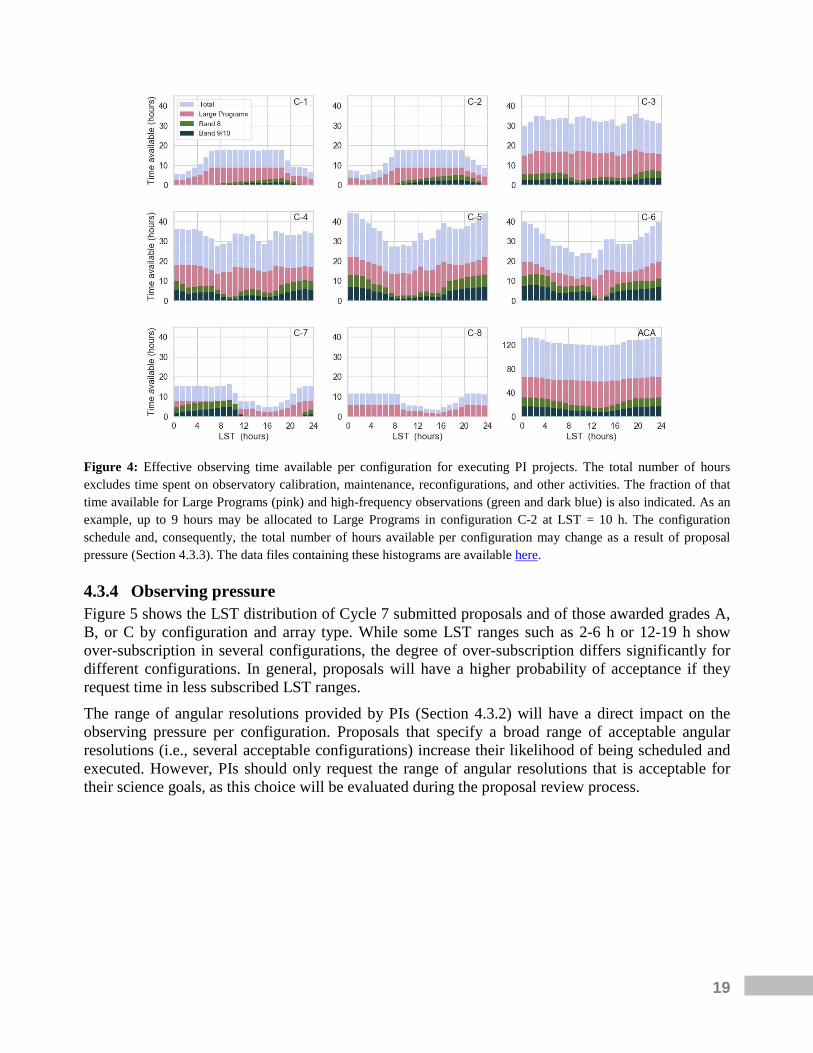
Figure 4: Effective observing time available per configuration for executing PI projects. The total number of hours excludes time spent on observatory calibration, maintenance, reconfigurations, and other activities. The fraction of that time available for Large Programs (pink) and high-frequency observations (green and dark blue) is also indicated. As an example, up to 9 hours may be allocated to Large Programs in configuration C-2 at LST = 10 h. The configuration schedule and, consequently, the total number of hours available per configuration may change as a result of proposal pressure (Section 4.3.3). The data files containing these histograms are available here.
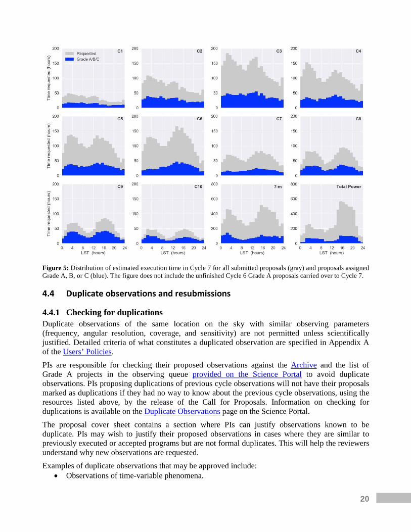
4.3.4 Observing pressure Figure 5 shows the LST distribution of Cycle 7 submitted proposals and of those awarded grades A, B, or C by configuration and array type. While some LST ranges such as 2-6 h or 12-19 h show over-subscription in several configurations, the degree of over-subscription differs significantly for different configurations. In general, proposals will have a higher probability of acceptance if they request time in less subscribed LST ranges. The range of angular resolutions provided by PIs (Section 4.3.2) will have a direct impact on the observing pressure per configuration. Proposals that specify a broad range of acceptable angular resolutions (i.e., several acceptable configurations) increase their likelihood of being scheduled and executed. However, PIs should only request the range of angular resolutions that is acceptable for their science goals, as this choice will be evaluated during the proposal review process.
20
Figure 5: Distribution of estimated execution time in Cycle 7 for all submitted proposals (gray) and proposals assigned Grade A, B, or C (blue). The figure does not include the unfinished Cycle 6 Grade A proposals carried over to Cycle 7.
4.4 Duplicate observations and resubmissions
4.4.1 Checking for duplications Duplicate observations of the same location on the sky with similar observing parameters (frequency, angular resolution, coverage, and sensitivity) are not permitted unless scientifically justified. Detailed criteria of what constitutes a duplicated observation are specified in Appendix A of the Users’ Policies. PIs are responsible for checking their proposed observations against the Archive and the list of Grade A projects in the observing queue provided on the Science Portal to avoid duplicate observations. PIs proposing duplications of previous cycle observations will not have their proposals marked as duplications if they had no way to know about the previous cycle observations, using the resources listed above, by the release of the Call for Proposals. Information on checking for duplications is available on the Duplicate Observations page on the Science Portal. The proposal cover sheet contains a section where PIs can justify observations known to be duplicate. PIs may wish to justify their proposed observations in cases where they are similar to previously executed or accepted programs but are not formal duplicates. This will help the reviewers understand why new observations are requested. Examples of duplicate observations that may be approved include:
• Observations of time-variable phenomena.

21
• A large-area survey where cutting out a smaller area to avoid overlap with a previous observation will make the observation inefficient and increase the overall execution time.
• Spectral scan surveys where excluding a frequency range covered by a previous observation will make the observation inefficient and increase the overall execution time.
4.4.2 Resubmission of an unfinished proposal Proposal teams that submit a Cycle 8 2021 proposal to observe some or all the SGs of a currently active but unfinished project will have the relevant SGs identified as a “resubmission”. An SG is deemed a resubmission if it constitutes a duplication of an active SG following the rules specified in Appendix A of the Users’ Policies and the PI of the relevant Cycle 7 project is listed as a PI, co-I or co-PI of the corresponding Cycle 8 2021 proposal or the Cycle 8 2021 PI is listed as an investigator on the Cycle 7 proposal. For such resubmissions, the relevant portion of the Cycle 8 2021 proposal will be cancelled if the observations are successfully completed in Cycle 7. Observations started in a previous cycle and accepted as a resubmission in Cycle 8 2021 will continue to be observed with the setup of the previous cycle. A Scientific Justification must be provided if the proposers request one or more additional epochs of observations in Cycle 8 2021 even if the Cycle 7 observations are completed.
4.5 Estimated observing time Proposal requests are cast in terms of SGs, each containing a complete observational setup (desired sensitivity, range of angular resolutions and LAS, frequency band, spectral windows, and spectral resolutions) to be applied for one or more targets. The OT Quickstart Guide and the OT User Manual provide extensive details and guidance for preparing the SGs. Experienced users who wish to understand how ALMA observations are set up may refer to Chapter 8 of the Technical Handbook. The observational setup of a given SG is used to estimate a total observing time for that SG (except for Solar or VLBI observations or when overridden by the PI - see Appendix B). This observing time is the sum of the required time on source for all science targets, time for all calibrations including overheads, and the time for any additional array configurations needed to meet the specified LAS. The estimated observing time for the proposal is the sum of the times for all SGs. The actual observing time to reach a given sensitivity, resolution, and LAS will depend on the prevailing conditions when the project is observed, the number of antennas available, and the actual array configuration. The estimated time on source is calculated with the ALMA Sensitivity Calculator (ASC), available within the OT or as a stand-alone web application on the Science Portal. The parameters that affect these time estimates include requested sensitivity, source declination, observing frequency, spectral bandwidth, number of antennas, angular resolution (if the sensitivity is specified in temperature units5), and default weather conditions. A description of the ALMA Sensitivity Calculator is given in Chapter 9 of the Technical Handbook. The estimated time for calibrations and overheads is calculated by the OT and will depend on the frequency, configuration, and type of observation (e.g. full polarization requires additional calibrations). Proposals requesting the suppression of some or all calibrations in one or more SGs 5 Since Cycle 5, the time estimate adopts the configuration that fulfills the highest angular resolution requested if the sensitivity is specified in temperature units (Section 4.3.3).

22
may be deemed technically infeasible if the request is not properly justified in the proposal (see Section B.4 for details). For each SG, one or more SBs are generated during Phase 2 depending on the distribution of sources in the sky and the number of configurations needed (Sections A.8.1 and A.4, respectively). Each SB contains all the commands needed to perform the observations and a complete set of calibrations. The minimum duration of the SB is constrained by a minimum time on source of 5 minutes for the sum of all the sources in the SB or 50% of the total calibration time (see Section 5.3.5.3 of the OT User Manual). For SGs that require a combination of arrays but have short time on source that is increased to the 5-minute minimum by the OT, the time multipliers given in Table A-2 may not be preserved (see Section A.4). The maximum duration of a SB is around 2 hours (determined by a maximum time on source of 50 minutes) and each SB will be re-run as many times as needed to achieve the requested signal-to-noise (S/N) ratio. Consecutive executions of a given SB (if needed) are favored during scheduling to maximize uv-coverage. However, if uv-coverage is fundamental for the scientific goals of a proposal, PIs should specify this request as a time constraint and, if necessary, override the OT time estimate with the time needed to achieve such uv-coverage (see Section B.2 for details). Data from each SB will be processed, assessed, and delivered independently. The final factor in the time estimate is the possible addition of configurations needed to reach the LAS specified by the user. The LAS is compared to the “Maximum Recoverable Scale” (MRS) of the configurations that best match the requested range of angular resolutions. The MRS for each configuration is listed in Table A-1. If the LAS exceeds the MRS of all matching configurations, then additional configurations, if allowed (Section A.4), are added with a time estimated using the multipliers given in Table A-2. If the array combinations are not allowed (Section A.4), the OT will give a validation error. If the LAS can be achieved with one or more of the best-matching configurations, the remaining configurations meeting the angular resolution but not the LAS request will not be considered. The PI may include additional SGs for array combinations not allowed in a single SG, but each SG must be separately justified and have its own performance specifications (sensitivity, range of angular resolutions, and LAS). Observations that require only the ACA are selected by checking a specific box in the OT interface. When calculating the time required for the ACA, for each Science Goal the OT uses the TP Array time if this array is required (based on LAS) or otherwise the 7-m Array time; i.e., it is not the sum of the 7-m and TP Array time. In case of simultaneous observations in the 12-m and 7-m Arrays, the estimated time for the 7-m Array will be set equal to that of the 12-m Array. Users should note that snapshots with the 7-m Array are strongly discouraged for imaging. Integrations of at least one hour are necessary for sufficient uv-coverage to achieve good image quality. See Chapter 7 of the Technical Handbook for more information on imaging with ALMA. Time estimates for each SG are available in the OT by clicking “Time Estimate” in the “Desired performance” box. A summary of the time estimate of each SG can be viewed by clicking the “Time Summary” button on the OT toolbar. The times for the 12-m Array, 7-m Array, and TP Array are tabulated separately on the proposal cover sheet.
23
4.6 Supporting tools and documentation
4.6.1 The Observing Tool documentation The ALMA OT, a Java-based application that resides and runs on the user’s computer, is used to prepare and submit observing proposals (Phase 1) as well as to prepare the observations for execution on the telescope (Phase 2) if the proposal is accepted. The OT is most conveniently installed using the new installer option, which is available for Linux, Mac OS, and Windows. The installer contains its own version of Java and thus it is not necessary for users to install Java themselves. The OT documentation suite, which provides all the basic information required to complete the proposal preparation and submission, includes:
• The OT Phase 1 Quickstart Guide: A guide to proposal preparation for the novice ALMA OT user. It provides an overview of the necessary steps to create an ALMA observing proposal.
• The OT Video Tutorials: A visual demonstration of proposal preparation and submission with the OT. Users should note that these videos were produced in Cycle 6 and therefore do not include the changes implemented since then.
• The OT User Manual: A manual intended for all ALMA users, from novices to experienced users. It provides comprehensive information on creating valid Phase 1 proposals and Phase 2 programs for observing astronomical objects. It is also included as part of the “Help” documentation within the OT itself.
• The OT Reference Manual: A manual providing a concise explanation for all the fields and menu items in the OT. It is also included as part of the “Help” documentation within the OT itself.
• The OT trouble-shooting page: A list of the OT installation requirements and workarounds for common installation problems.
• The known OT issues page: A list of known bugs, their status, and possible workarounds. This page may be updated during the proposal submission period and should be checked first if problems are experienced with the OT.
4.6.2 Additional proposal preparation tools Two tools are available to help users produce simulated images of ALMA observations of simple or user-provided science targets. A guide for simulating ALMA observations with either tool is available at the CASA guides website. The first simulation tool is integrated into CASA, the offline data reduction and analysis tool for ALMA data. CASA includes the tasks “simobserve” and “simanalyze”, which generate simulated visibility data and make images from these simulated data sets. An additional CASA task, “simalma”, simplifies the process for ALMA data by combining data from multiple arrays, including the TP Array, if needed. These CASA tasks require configuration files that specify the layout of ALMA antennas. To simulate observations for Cycle 8 2021, investigators should use the equivalent Cycle 7 configuration files available on the Science Portal. The CASA simulation tasks are included in the CASA documentation and detailed examples can be found in the CASA guides. Additional
24
information on CASA, including hardware requirements and download instructions, is available at the CASA website. The second simulation tool is the ALMA Observation Support Tool (OST). The OST uses a simplified web interface to help users generate ALMA simulations. Users submit jobs to the OST and are notified by email when the simulations are completed. The OST documentation is available at the OST website. Splatalogue is a database containing frequencies of atomic and molecular transitions emitting in the radio through submillimeter wavelength range. This database is used by the ALMA OT for spectral-line selection. More information is available in the Splatalogue QuickStart Guide. The atmospheric transmission at the ALMA site can be investigated with the Atmosphere Model tool, which allows the user to model the atmospheric transmission as a function of frequency and PWV. The output is a plot of the transmission fraction as a function of frequency. Up to six different water vapor levels can be selected.
4.6.3 The ALMA Regional Center guides The ARC Guides contain user support details specific to each ALMA regional partner. They are:
• The East-Asian ARC Guide
• The European ARC Guide
• The North American ARC Guide
4.6.4 Supplemental documentation The following documents supplement this Proposer’s Guide for the preparation of Cycle 8 2021 proposals, for either the novice or advanced users. All documents can be accessed via the ALMA Science Portal. The Proposing Guidance page from the Science Portal summarizes the steps involved in the preparation and submission of an ALMA observing proposal. It is designed to help users find the relevant documents and sources of additional information in each step of creating a proposal. Observing with ALMA: A Primer is a brief introduction to ALMA observing, submillimeter terminology, and interferometric techniques that should prove useful for those new to radio astronomy. Several example science projects are described. The ALMA Users’ Policies document contains a complete description of the applicable users’ policies. The long-term core policies for usage of ALMA and of ALMA data by the user community are presented. The ALMA Cycle 8 2021 Technical Handbook describes the technical details of ALMA during Cycle 8 2021, including but not limited to receiver characteristics, array configurations, available observing modes, and correlator setups, and the basis of the OT time estimates. The ALMA Memo Series and ALMA Technical Notes Series include technical reports on various aspects of ALMA project development and construction and from the extension and optimization of capabilities.
25
4.7 The ALMA Helpdesk The ALMA Helpdesk can be accessed from the ALMA Science Portal or directly at http://help.almascience.org. Submitted tickets are directed to the user’s ARC, where support staff are available to answer any question related to ALMA, including but not limited to ALMA policies, capabilities, documentation, proposal preparation, the OT, Splatalogue, and CASA. Users may also request information on workshops, tutorials, or about visiting an ARC or ARC node for assistance with data reduction and analysis. The Observatory will create a project ticket for each accepted proposal. Investigators can use this ticket for questions and communication on their project throughout its lifetime. Finally, investigators can also trigger ToO observations using the Helpdesk (see Section 3.2 ). Users must be registered at the ALMA Science Portal to submit a Helpdesk ticket. Replies to an already existing ticket can be sent by the user by logging into the SP or via email (see "Can I respond to my helpdesk ticket through my email?" for more details). ALMA staff aim to answer Helpdesk tickets within two working days. The “Knowledgebase” of the Helpdesk is a database of answered questions and articles on all aspects of ALMA. Users can search the Knowledgebase to find answers to common queries. Knowledgebase articles that match their query are automatically suggested to users as they type. The Knowledgebase query interface also searches all the documentation available on the ALMA Science Portal and provides a direct link to the documentation that may answer a user’s question.
5 Proposal preparation and submission The following sections contain guidelines regarding proposal format and preparing the Scientific and Technical Justification. The setup of Science Goals is only briefly explained here. Users are referred to the extensive suite of OT documentation for details (Section 4.6.1). ALMA novices are encouraged to start with the OT Quickstart Guide and the video tutorials.
5.1 Proposal format An ALMA proposal consists of basic proposal information that is entered directly into the ALMA OT (Section 4.6.1), a Science Justification uploaded to the OT as a PDF file, and one or more Science Goals. Science Goals contain the technical details of the proposed observations and must include a Technical Justification. The OT is designed to facilitate proposal preparation and includes a number of tools and checks to ensure submitted proposals conform to the Cycle 8 2021 capabilities. After entering the basic proposal information and completing the Science Goals in the OT, the PI can generate the PDF of the complete proposal, including the Scientific Justification, Science Goals, and Technical Justification that will be distributed to the reviewers for evaluation. The first page of the PDF (the “cover sheet”) includes the title and abstract together with a summary of the SGs. In Cycle 8 2021, ALMA is implementing dual-anonymous review so the names of investigators will not be listed on the cover sheet or elsewhere in the PDF seen by the reviewers.
26
5.2 Dual-Anonymous proposal review To ensure that the proposal review process is as fair and unbiased as possible, ALMA is beginning dual-anonymous review in Cycle 8 2021. In a dual-anonymous review, the proposal team does not know the identity of the reviewers and the reviewers do not know the identity of the proposal team. While proposers will still enter their names and affiliations in the OT, this information will not appear on the proposal cover sheet, nor in the tools used by the reviewers. It is the responsibility of the proposers to ensure anonymity is preserved when writing their proposals. Details and specific guidelines on how to write your proposal following the dual-anonymous requirements are provided in the Guidelines for Dual-Anonymous Proposals on the Science Portal. Proposers with resubmissions are encouraged to be particularly cognizant of changes needed in their text. All proposers are encouraged to use the Helpdesk for any questions relating to dual-anonymous review.
5.3 Preparing the Scientific Justification ALMA Cycle 8 2021 proposals must include a single PDF document that includes a science case written in English. The document may include figures, tables, and references. The maximum permitted file size is 20 MB.
5.3.1 Page limits and fonts The total length of the PDF document is limited to four pages for Regular, ToO, mm-VLBI, and DDT proposals and six pages for Large Programs (A4 or US Letter format), with a font size no smaller than 12 points. The OT will check the font size of the PDF and issue an error during proposal validation if more than 15% of the text is smaller than 12 points. To submit the proposal, any problems with small fonts must first be fixed. Note that the OT may issue errors by detecting “hidden text” when figures are cropped from other PDFs. See the Knowledgebase article on font size problems for further details. The recommended breakdown is two pages for the science case and two pages for figures, tables, and references, but proposers are free to adjust these numbers within the overall page limit. The document for Large Programs, which are allotted two additional pages, must also include a description of the data products, the publication plan, and a discussion of the scheduling feasibility. New for Cycle 8 2021, Large Programs will be required to submit a separate one-page PDF document with their management plan through the OT at the time of proposal submission. This document must describe the roles and responsibilities of the proposal team as well as the computing resources available to the team. Figures and tables may be embedded within the science case so that they appear close to the location where they are referenced in the text. Although the Technical Justification for each Science Goal is entered in the OT, any figure required for it needs to be placed in the Scientific Justification PDF document. Users are encouraged to prepare their Scientific Justifications using the LaTeX template available on the Science Portal. Proposals must be self-contained. Reference can be made to published papers (including arXiv.org preprints) as per standard practice in the scientific literature. Consultation of those references should not, however, be required for understanding the proposal.

27
5.3.2 Science case Each proposal must describe the scientific importance of the proposed project and include a clear statement of its immediate observing goals. It is also recommended to provide a brief justification of the requested sensitivity and angular resolution, with full details provided in the Technical Justification (Section 5.3). Proposers can simulate ALMA observations using different array components and configurations (see Section 4.6.2). Simulations are not required. However, if they are discussed in a proposal to justify any technical aspects of an observation, their results (i.e., images and simulation details) should be included in the Scientific Justification and referenced in the relevant Technical Justification. Since proposal reviewers are selected with expertise that covers the various topics within a proposal category, the Scientific Justification should be written for a knowledgeable but broad-based audience.
5.3.3 Figures, tables, and references Figures, tables, and references that support the science case and the Technical Justification may be included. Figure captions, tables and references must use 12-point font and, together with the science case, must fit within the overall page length and 20 MB size limit of the PDF proposal.
5.4 Preparing the Technical Justification Each SG within a proposal must contain a Technical Justification (TJ), which is entered directly into the OT in the TJ node of each SG. Any figures associated with the TJ must be included in the Scientific Justification PDF file and clearly referenced in the TJ. The TJ must include a quantitative description and justification of the expected source brightness, the requested sensitivity and S/N ratio, angular resolution, and spectral setup. An incomplete TJ may lead to the rejection of the proposal on technical grounds. Each SG has its own TJ since the technical setup of the observations will often vary substantially from one SG to the next. If a TJ is applicable to more than one SG, the TJ node can be easily copied and pasted (or dragged and dropped) between SGs. The TJ node contains three sections – sensitivity, imaging, and correlator configuration - corresponding to the main aspects that need to be assessed for the technical feasibility of any proposal. Each section includes at least one free-format text box that must be filled in (50 characters minimum), as well as a number of parameters computed from the user input captured in that Science Goal. This information is designed to help with the writing of the TJ, and will also highlight potentially problematic setups (blue text) if applicable. Please see the relevant sections in the OT Reference Manual (accessible by clicking the “?” symbols within the OT) for details. If the OT detects any technical choices that require an extra justification (e.g., time-constraints), appropriately labelled text boxes will appear in an additional "Choices to be justified" section. Given that the information and the text boxes displayed in the TJ node are dependent on information provided elsewhere in the SG (including the Expected Source Properties entered in the Field Setup node), the Science Goal should be completed before filling in the TJ. Specific guidelines on filling out the TJ are given in Appendix B.
28
If a proposal does not conform to the advertised capabilities, it can be declared technically infeasible either during the proposal review process or during Phase 2 (Section 6.1). The final decision will be made by the Head of Science Operations at the JAO. The TJ must abide by the guidelines of dual-anonymous review.
5.5 Proposal validation, submission and withdrawal Once the proposal is validated within the OT, it can be submitted to the ALMA Archive. Validation could take up to 5 minutes (or longer!) if the program contains complicated setups or a large number (hundreds) of sources. PIs of such programs should submit their proposals well before the deadline. A proposal can be updated and submitted again to the ALMA Archive as many times as needed by the PI before the proposal deadline. Each time a proposal is submitted, the previous version of the proposal is overwritten (Section 5.5.1). Submitted proposals cannot be modified after the deadline. DDT proposals are not overwritten when submitted again, so they should only be submitted once. Proposals to the Main Call will be accepted starting 15:00 UT on 17 March 2021 and continue until the proposal deadline at 15:00 UT on 21 April 2021. No proposal submission or update will be accepted after the deadline. It is the PI’s responsibility to submit the proposal successfully before the deadline. PIs are encouraged to submit their proposals early. In addition, the following considerations apply:
• PIs, co-Is and co-PIs can retrieve proposals from the Archive both before and after the deadline.
• PIs who successfully submit their proposal will receive a confirmation e-mail from ALMA that includes the assigned project code.
• DDT proposals may be submitted at any time. Like all other proposals, they must include a detailed science case and Technical Justification.
• A Helpdesk ticket should be submitted if the PI needs to withdraw a proposal that has already been assigned a project code.
5.5.1 Proposal updates PIs who need to update and then resubmit a proposal should ensure that this is done using the last submitted version either by (i) modifying the proposal saved after submitting it, or (ii) downloading and then modifying the submitted proposal from the Archive. If a PI tries to submit a version of the proposal that had been saved on disk before it was first submitted, it will be rejected by the Archive. An earlier version that was never submitted (and which therefore contains no proposal code) will produce a new (duplicate) submission with a new code. Users wishing to generate a new proposal starting from a proposal from the current submission period should save the original one to disk before it has been submitted. Otherwise, the second proposal will contain the original proposal’s code and will overwrite it when submitted. Alternatively, the OT's "Open Project as New Proposal" (available from the File menu) could be used.

29
5.6 Proposal evaluation and selection
5.6.1 Peer review ALMA will adopt a distributed peer review process for scientific review of most proposals submitted to Cycle 8 2021. Proposals requesting less than 25 hours on the 12-m Array and all ACA stand-alone proposals requesting less than 150 hours on the 7-m Array will be evaluated in this way. Unless submitting a Large Program, the PI must designate someone from the proposal team as the reviewer at the time of submission. In most cases the PI will be the designated reviewer. After the proposal deadline, the Proposal Handling Team (PHT) at the Joint ALMA Observatory (JAO) will assign ten proposals to the designated reviewer of each proposal. The proposal assignment will be done based on the expertise of the designated reviewer as specified in their user profile.6 The assignment process will also consider possible conflicts of interest. If reviewers identify a conflict of interest that was not spotted during the proposal assignment, they can request a replacement proposal through the Reviewer Tool. Then during Stage 1, the reviewer will rank the ten proposals (1-10) in order of scientific priority and write a brief review for each proposal. If ranks and reviews are not submitted by the Stage 1 review deadline at 15:00 UT on 03 June 2021, the proposal on which the reviewer is acting as the designated reviewer will be rejected. After the Stage 1 review deadline, each reviewer will have the option to participate in Stage 2 of the review process, where the anonymized comments from the other reviewers of the same proposals will be made available. Reviewers can modify their own ranks and comments if desired in Stage 2. Once this second stage is completed, the ranks from all reviewers of each submitted proposal will be combined to produce a global ranked list of proposals. Any PI and most co-Is can be designated as a reviewer. If the PI does not have a Ph.D. at the time of proposal submission (e.g., a student), the PI can still be the reviewer, but a mentor (who must have a Ph.D.) must be identified at the time of the proposal submission. A PI may designate a co-I as the reviewer as long as the co-I has a Ph.D. in astronomy or a closely related field. The reviewer and (if needed) mentor must be designated in the OT at the time of proposal submission. Large Programs and other proposals requesting more than 25 hours on the 12-m Array will continue to be reviewed by individual ALMA Review Panels (ARPs) that are specialized in a scientific category. The JAO assigns each submitted proposal to a panel based primarily on the science category selected by the PI (see Appendix D for the list of scientific categories), but with care taken to avoid conflicts of interest with the ARP members. Note that even though proposals requesting between 25 and 50 hours on the 12-m Array will be reviewed by panels, PIs of those proposals are still required to designate a reviewer for the OT to validate the proposal. The ALMA Proposal Review Committee (APRC) will then review the Large Programs selected by the ARPs and recommend which to schedule. After the outcome of the proposal review process is approved by the ALMA Director’s Council and a Chilean representative, the results will be communicated to the PIs. The notifications will include the assigned grade and a consensus report from the ALMA review panels that summarizes the strengths and weaknesses of the proposal.
6 We encourage all ALMA users to go to the ALMA Science Portal to update their user profiles and select keywords pertaining to their expertise. The distributed review proposal assignment algorithm will use the selected keywords of the reviewer’s expertise for matching assignments; if reviewers do not submit them, the algorithm will use the keywords of the submitted proposal. Review assignment matching is therefore optimized for individual reviewers' expertise when the information provided in the users’ profile is up to date and accurate.
30
Additional details about the review process, such as guidelines for the reviewers and the expected timeline, are available on the Proposal Review section of the Science Portal.
5.6.2 Evaluation criteria The primary criteria to rank all proposals are the overall scientific merit of the proposed investigations and their potential contribution to the advancement of scientific knowledge. The JAO will also evaluate the proposals for technical feasibility to ensure they are consistent with Observatory best practices. Given the significant investment of ALMA resources for Large Programs, the APRC will also consider the following factors for these programs:
• Scheduling feasibility A Large Program should be designed such that the observations are likely to be completed within Cycle 8 2021 given the antenna configuration schedule and weather constraints (see Sections 3.3 and 4.3). The JAO will evaluate the scheduling feasibility of each Large Program and notify the APRC of the results
• Data products and publication plan A Large Program should describe the data products that will be produced to achieve their science goals and present a plan to publish the results of the project. The program teams will be expected to deliver these data products to the ARCs so that they can be made available to the community at large.
• Management plan The APRC will evaluate the management plans to assess if the proposal team is prepared to complete the project in a timely fashion, both in terms of personnel and computing resources. The management plans will be evaluated only after the APRC has completed the scientific rankings of the Large Programs. The evaluation of the management plan will not be used to modify the scientific rankings. Any concerns that the APRC has about the management of a Large Program will be communicated to the ALMA Director, who will make the final decision on whether to accept the proposal. Contact your ARC through the Helpdesk for assistance.
5.6.3 Proposal selection The JAO will take the results from the panel review, the APRC, and the distributed peer review to form an observing queue based primarily on the scientific rankings from the review process.7 When forming the observing queue, the JAO will also take into account the scheduling constraints dictated by the configuration schedule and weather, the share of observing time for each region, and the time constraints on Large Programs and VLBI. Up to 33% of the nominal time specified in Section 4.1 will be assigned to Grade A proposals and 67% to Grade B proposals. Grade C will be assigned to proposals for filler time to ensure that an adequate number of projects are available for all configurations and LST ranges in case the actual observing efficiency or weather conditions differ from expectations. The shares of the observing time among the regions are:
7 For VLBI proposals, both ALMA and the appropriate VLBI network must accept a given proposal for the observations to be scheduled.
31
• 33.75% for the European Organisation for Astronomical Research in the Southern Hemisphere (ESO).
• 33.75% for the National Science Foundation of the United States (NSF). • 22.5% for the National Institutes of Natural Sciences of Japan (NINS). • 10% for the Chilean community, which is administrated jointly by the Comisión Nacional de
Investigación Científica y Tecnológica (CONICYT) and the Universidad de Chile.
All regions contribute toward “Open Skies” to enable all eligible Principal Investigators to apply for ALMA time.
5.7 Proposal confidentiality For proposals assigned Grade A or B, the project code, the proposal title and abstract, the name and region of the PI, and the names of co-Is (and co-PIs, in the case of Large Programs or VLBI proposals) will be made public soon after PIs are informed of the outcome of the proposal review process. For proposals assigned Grade C, the corresponding information will be made public as soon as its first data are archived. Proposal metadata (for example the source positions, observation frequencies, and integration times) for Grade A will become public soon after the proposal review process is completed. For Grade B and C proposals, metadata will be made public as soon as the first data are archived. The metadata for unaccepted proposals or unobserved Grade B or C proposals will remain confidential. The Scientific and Technical Justifications of all submitted proposals remain confidential, except for proposals for 1.3 mm VLBI proposals, which will be sent for technical review by the EHTC VLBI network.
6 Post-proposal activities
6.1 Observations preparation and submission: Phase 2 Once a project has been approved for scheduling, the project passes into Phase 2. Unlike in previous cycles, PIs will not be required to submit Phase 2 Science Goals in Cycle 8 2021 (see ALMA Users’ Policies for further details). Each approved project will be assigned an ALMA Contact Scientist (CS) at the associated ARC or ARC node and a project Helpdesk ticket will be opened on behalf of the PI for communication with the CS and others. Necessary minor changes may be requested through this Helpdesk ticket and will be implemented as long as they do not impact the science scope or increase the total execution time. Any significant change may only be made after the approval of a PI-initiated change request through the Helpdesk (Section 6.2). The CS can assist the PI with any questions during Phase 2. ALMA staff will generate the Scheduling Blocks and, in case of problems, will contact the CS and the PI. If no problems are found, the project will be submitted to the ALMA observing queue to await execution at the telescope. PIs may track the status of their SBs through the Snooping Project Interface (SnooPI), accessible from the ALMA Science Portal. For approved Solar observations, the ALMA Observatory will coordinate with the PI to get an updated target ephemeris at least 24 hours in advance of the proposed observation. PIs of

32
observations with ephemeris targets other than the Sun are responsible for providing a valid target ephemeris file during the Phase 2 process and any updates during the Cycle if necessary.
6.2 Changes to submitted programs Changes to a submitted proposal will not be permitted prior to the completion of the review process. Therefore, PIs should carefully check source coordinates, frequency and angular resolution settings, and calibration needs before submitting their proposal. PIs are encouraged to use the Helpdesk if they need support. PIs of proposals assigned a grade of A, B, or C may request changes to their projects subject to the ALMA Change Request policies described in the Users’ Policies. Minor changes can usually be made during the Phase 2 process. Major changes are allowed only if additional information that may seriously affect the scientific case of the project has become available since the time of submission, when there is a demonstrable mistake, or when there is the potential for interesting scientific optimization. All change requests are made through the ALMA Helpdesk. The request must include a clear description of the proposed change along with a clear, substantive justification for the change. Major change requests are treated case-by-case and evaluated taking into account the increase in science scope, change of observing time, changes in the observing setups, and other factors. Change requests leading to duplications against ALMA proposals in the observing queue or archival observations will not be approved.
6.3 Data processing and data delivery ALMA staff, assisted by the data reduction pipeline, will conduct quality assurance on ALMA data and will provide processed data products through the respective ARC archives. Quality Assurance Level 2 (QA2) is performed on the data that result from all executions of an SB. In particular, the data are checked for calibration accuracy and to assure there are no imaging artifacts (see ALMA QA2 Data Products for more details). Data that meet the PI-specified goals within cycle-specific tolerances (see Chapter 11 of the Technical Handbook) are made available to the PI. Once the products have been identified as suitable for delivery, the PI is notified that the data are available for download through the ALMA Archive. PIs are requested to check the delivered data as soon as practical. For a more complete description of the Quality Assurance process, see Section 6.3 of the ALMA Users’ Policies and Chapter 11 of the Technical Handbook. If the PI discovers a problem in the delivered data other than any caused by a PI mistake, they must submit a Quality Assurance Level 3 (QA3) request to the Helpdesk as soon as possible, since such problems will have implications for re-observations and the proprietary period. By default, data obtained as part of an ALMA science program are subject to a proprietary period of 12 months (except DDT programs, which have 6 months), starting for each data package when the PI is notified that the data are available (see Section 8.4 of the ALMA Users’ Policies). At any time, a PI can request access to raw data for any execution that has passed Quality Assurance Level 0 (QA0). This request comes at the expense of the start of the proprietary period. Once the raw data are staged for PI access, the proprietary time starts for that SB. See Section 8.4 of the ALMA Users’ Policies for more details on requesting raw data or contact the ARC for support.
33
6.4 Opportunities for public promotion of ALMA If the PI believes their results are newsworthy or of interest to a broader community, the PI should contact the ALMA Education and Public Outreach (EPO) team to develop materials for presentation to the media and the public (e.g., press releases), including support in the preparation of visuals, if relevant. EPO may ask for cooperation on the scientific content and for the PI to be available for possible interviews. The e-mail address for the ALMA EPO team is [email protected].

34
Appendix A ALMA Cycle 8 2021 Capabilities This appendix describes the characteristics and capabilities of the ALMA Observatory offered for the Cycle 8 2021 observing season. All submitted proposals must be compliant with these capabilities or they will be judged as infeasible. Where possible, the ALMA OT has validation checks to warn or prevent entering unallowed values.
A.1 Number of antennas At least forty-three 12-m antennas in the main array (hereafter the 12-m Array) will be offered. The ACA will have available at least ten 7-m antennas (hereafter the 7-m Array) for short baselines and three 12-m antennas (hereafter the Total Power Array or TP Array) for making single-dish maps. The ACA will be offered both to complement observations with the 12-m Array and as a stand-alone capability. The stand-alone ACA is offered either with the 7-m Array alone or with the 7-m Array and TP Array combined. The OT currently does not permit users to request only the TP Array. However, if a user has existing 7-m Array data through their own program or through archival data, but now realizes that TP Array data are needed to obtain short spacings, they can submit a proposal requesting both the 7-m Array and TP Array. The proposal should indicate that only the TP Array is needed and that the 7-m Array should be descoped if the proposal is accepted. This option is available only if the 7-m Array data have already been obtained. Proposals requesting stand-alone ACA time are subject to certain restrictions, including no bandwidth switching, no Solar observations, no user-specified calibration, and no Astrometric observations. The use of the TP Array is limited to spectral-line observations (not continuum) in Bands 3 to 8. The number of antennas available may sometimes be fewer than the numbers given above due to unforeseen problems with the equipment, or during array reconfigurations. During these times, ALMA staff aim to schedule observations that will not be seriously affected by having a slightly smaller number of antennas and may increase the integration times or uv-coverage to compensate, whenever practical.
A.2 Array configurations As detailed in Section 4.5, a Science Goal is defined in terms of a desired range of angular resolutions (ARs) and the Largest Angular Structure (LAS) to be imaged. ALMA will meet these requirements by taking observations in one or more array configurations, which are characterized in terms of their AR and Maximum Recoverable Scale (MRS, the largest smooth angular structure to which a given array is sensitive – see Chapter 7 of the Technical Handbook for details). The properties of these configurations, and the allowed combinations, therefore define the imaging capabilities of ALMA. The antennas in the 12-m Array will be staged into configurations that transition from the most compact (with maximum baselines of ~160 m) up to the most extended configuration (maximum baselines of 8.5 km in Cycle 8 2021 and 16.2 km in Cycle 9). Ten 12-m Array configurations have been defined to represent the possible distribution of antennas over this range of maximum baselines. These are denoted as C-x, with x=1 for the most compact configuration and x=10 for the most extended. One 7-m Array configuration has been defined to represent the possible distribution of the ten 7-m antennas. The imaging capabilities of these configurations are given in Table A-1.
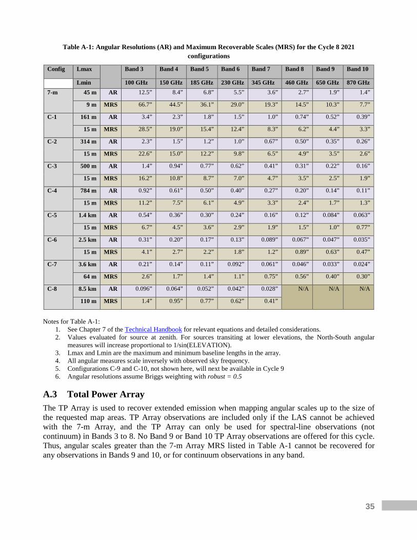
35
Table A-1: Angular Resolutions (AR) and Maximum Recoverable Scales (MRS) for the Cycle 8 2021 configurations
Config Lmax
Band 3 Band 4 Band 5 Band 6 Band 7 Band 8 Band 9 Band 10
Lmin 100 GHz 150 GHz 185 GHz 230 GHz 345 GHz 460 GHz 650 GHz 870 GHz 7-m 45 m AR 12.5” 8.4” 6.8” 5.5” 3.6” 2.7” 1.9” 1.4”
9 m MRS 66.7” 44.5” 36.1” 29.0” 19.3” 14.5” 10.3” 7.7”
C-1 161 m AR 3.4” 2.3” 1.8” 1.5” 1.0” 0.74” 0.52” 0.39”
15 m MRS 28.5” 19.0” 15.4” 12.4” 8.3” 6.2” 4.4” 3.3”
C-2 314 m AR 2.3” 1.5” 1.2” 1.0” 0.67” 0.50” 0.35” 0.26”
15 m MRS 22.6” 15.0” 12.2” 9.8” 6.5” 4.9” 3.5” 2.6”
C-3 500 m AR 1.4” 0.94” 0.77” 0.62” 0.41” 0.31” 0.22” 0.16”
15 m MRS 16.2” 10.8” 8.7” 7.0” 4.7” 3.5” 2.5” 1.9”
C-4 784 m AR 0.92” 0.61” 0.50” 0.40” 0.27” 0.20” 0.14” 0.11”
15 m MRS 11.2” 7.5” 6.1” 4.9” 3.3” 2.4” 1.7” 1.3”
C-5 1.4 km AR 0.54” 0.36” 0.30” 0.24” 0.16” 0.12” 0.084” 0.063”
15 m MRS 6.7” 4.5” 3.6” 2.9” 1.9” 1.5” 1.0” 0.77”
C-6 2.5 km AR 0.31” 0.20” 0.17” 0.13” 0.089” 0.067” 0.047” 0.035”
15 m MRS 4.1” 2.7” 2.2” 1.8” 1.2” 0.89” 0.63” 0.47”
C-7 3.6 km AR 0.21” 0.14” 0.11” 0.092” 0.061” 0.046” 0.033” 0.024”
64 m MRS 2.6” 1.7” 1.4” 1.1” 0.75” 0.56” 0.40” 0.30”
C-8 8.5 km AR 0.096” 0.064” 0.052” 0.042” 0.028” N/A N/A N/A
110 m MRS 1.4” 0.95” 0.77” 0.62” 0.41”
Notes for Table A-1:
1. See Chapter 7 of the Technical Handbook for relevant equations and detailed considerations. 2. Values evaluated for source at zenith. For sources transiting at lower elevations, the North-South angular
measures will increase proportional to 1/sin(ELEVATION). 3. Lmax and Lmin are the maximum and minimum baseline lengths in the array. 4. All angular measures scale inversely with observed sky frequency. 5. Configurations C-9 and C-10, not shown here, will next be available in Cycle 9 6. Angular resolutions assume Briggs weighting with robust = 0.5
A.3 Total Power Array The TP Array is used to recover extended emission when mapping angular scales up to the size of the requested map areas. TP Array observations are included only if the LAS cannot be achieved with the 7-m Array, and the TP Array can only be used for spectral-line observations (not continuum) in Bands 3 to 8. No Band 9 or Band 10 TP Array observations are offered for this cycle. Thus, angular scales greater than the 7-m Array MRS listed in Table A-1 cannot be recovered for any observations in Bands 9 and 10, or for continuum observations in any band.
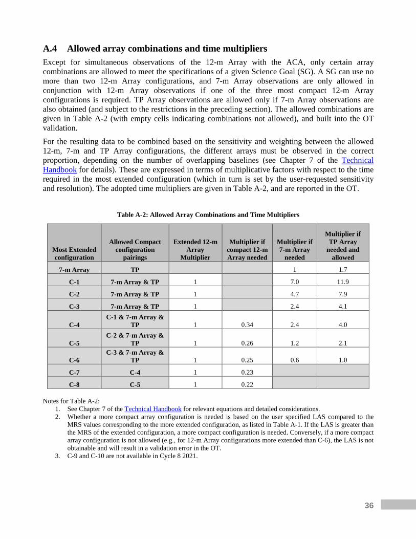
36
A.4 Allowed array combinations and time multipliers Except for simultaneous observations of the 12-m Array with the ACA, only certain array combinations are allowed to meet the specifications of a given Science Goal (SG). A SG can use no more than two 12-m Array configurations, and 7-m Array observations are only allowed in conjunction with 12-m Array observations if one of the three most compact 12-m Array configurations is required. TP Array observations are allowed only if 7-m Array observations are also obtained (and subject to the restrictions in the preceding section). The allowed combinations are given in Table A-2 (with empty cells indicating combinations not allowed), and built into the OT validation. For the resulting data to be combined based on the sensitivity and weighting between the allowed 12-m, 7-m and TP Array configurations, the different arrays must be observed in the correct proportion, depending on the number of overlapping baselines (see Chapter 7 of the Technical Handbook for details). These are expressed in terms of multiplicative factors with respect to the time required in the most extended configuration (which in turn is set by the user-requested sensitivity and resolution). The adopted time multipliers are given in Table A-2, and are reported in the OT.
Table A-2: Allowed Array Combinations and Time Multipliers
Most Extended configuration
Allowed Compact configuration
pairings
Extended 12-m Array
Multiplier
Multiplier if compact 12-m Array needed
Multiplier if 7-m Array
needed
Multiplier if TP Array
needed and allowed
7-m Array TP
1 1.7
C-1 7-m Array & TP 1
7.0 11.9
C-2 7-m Array & TP 1
4.7 7.9
C-3 7-m Array & TP 1
2.4 4.1
C-4 C-1 & 7-m Array &
TP 1 0.34 2.4 4.0
C-5 C-2 & 7-m Array &
TP 1 0.26 1.2 2.1
C-6 C-3 & 7-m Array &
TP 1 0.25 0.6 1.0
C-7 C-4 1 0.23
C-8 C-5 1 0.22
Notes for Table A-2: 1. See Chapter 7 of the Technical Handbook for relevant equations and detailed considerations. 2. Whether a more compact array configuration is needed is based on the user specified LAS compared to the
MRS values corresponding to the more extended configuration, as listed in Table A-1. If the LAS is greater than the MRS of the extended configuration, a more compact configuration is needed. Conversely, if a more compact array configuration is not allowed (e.g., for 12-m Array configurations more extended than C-6), the LAS is not obtainable and will result in a validation error in the OT.
3. C-9 and C-10 are not available in Cycle 8 2021.

37
If more than one configuration is needed to satisfy the AR and LAS constraints of a given SG, separate Scheduling Blocks (SBs) will be prepared during Phase 2 (Section 6.1) for each required configuration. These will be observed independently, and the data from the different SBs will be calibrated and imaged separately.
A.5 Receivers Bands 3 to 10 are available on all antennas. However, for Cycle 8 2021, observations with Bands 8, 9 and 10 will only be offered for configurations with baselines up to ~3.6 km, and Bands 3 to 7 up to ~8.5 km (see Section A.2). In addition, observations with Bands 9 and 10 will not be offered in the TP Array (see below). There are two types of receivers: dual-sideband (2SB), where the upper and lower sidebands are separated in the receiver and then processed separately, and double-sideband (DSB), where the sidebands are super-imposed coming out of the receiver but are separated in later processing. All bands receive dual linear polarizations (X and Y). Table A-3 summarizes the properties of the receiver bands offered in Cycle 8 2021. Details can be found in Chapter 4 of the Technical Handbook.
Table A-3: Properties of ALMA Cycle 8 2021 Receiver Bands
Band Frequency range1
(GHz) Wavelength range
(mm) IF range
(GHz) Type
3 84 – 116 3.6 – 2.6 4 – 8 2SB
4 125 – 163 2.4 – 1.8 4 – 8 2SB
5 158 – 211 1.9 – 1.4 4 – 8 2SB
6 211 – 275 1.4 – 1.1 4.5 – 10 2SB
7 275 – 373 1.1 – 0.8 4 – 8 2SB
8 385 – 500 0.78 – 0.60 4 – 8 2SB
9 602 – 720 0.50 – 0.42 4 – 12 DSB
10 787 – 950 0.38 – 0.32 4 – 12 DSB Notes for Table A-3:
1. These are the nominal frequency ranges for continuum observations. Observations of spectral lines that are within about 0.2 GHz of a band edge are not possible (at present) in Frequency Division Mode (FDM, see Section A.6.1) because of the responses of the spectral edge filters implemented in the correlator. IF is the intermediate frequency.
The capability to switch rapidly between receiver bands within the same SG (except for the purposes of data calibration) is not offered. Water Vapor Radiometer (WVR) measurements to correct for fluctuations in atmospheric water vapor are available for all 12-m antennas. No WVRs are installed in the ACA 7-m antennas and no WVR corrections will be applied to 7-m Array observations.

38
Bands 9 and 10 considerations For Bands 9 and 10 observations, PIs should take the following considerations into account. Since the sidebands can be separated reliably only in interferometric observations, single-dish Bands 9 and 10 observations with the TP Array will not be offered in Cycle 8 2021. At Bands 9 and 10, a special correlator mode (90-degree Walsh Switching) is available. For every spectral window defined by the user, enabling this feature will produce another spectral window in the other sideband, mirrored around the value of Local Oscillator 1 (LO1). This mode doubles the continuum bandwidth to 15 GHz, thus producing a √2 improvement in sensitivity or reducing the time required to achieve a particular sensitivity by a factor of 2. In addition, the greater bandwidth coverage allows more spectral lines to be observed simultaneously, although aligning the spectral windows such that they cover additional transitions is difficult and thus this mode is currently restricted to the widest-bandwidth spectral windows. In Cycle 8 2021, 90-degree Walsh Switching will be activated by default for continuum and spectral-line setups, although for the latter it will be possible (but not recommended) to deactivate it. Owing to the complexity of the atmospheric absorption in Bands 8, 9, and 10, calibration will be more problematic (also the high-frequency end of Band 7). Bands 9 and 10 ACA 7-m Array observations will be more difficult to calibrate than the corresponding 12-m Array observations since the rapid atmospheric phase correction cannot be applied and the smaller collecting area will limit the network of usable calibrators. In particular, bright calibrators are sparse at these high frequencies. When possible, the JAO will include 12-m dishes from the TP Array in the 7-m Array observation to support calibration; no special action or request is required by the PI. All these factors, together with the limited uv-coverage, will affect imaging at Bands 9 and 10 and will limit the achievable dynamic range with the ACA 7-m Array. Imaging dynamic ranges up to 50 are typical for these bands (see Section A.9.1 for more details). No mosaics are offered for Band 10 observations.
A.6 Spectral capabilities
A.6.1 Spectral windows, bandwidths and resolutions The ALMA Intermediate Frequency (IF) system provides up to four basebands (per parallel polarization) that can be independently placed within the two receiver sidebands. For 2SB receivers (Bands 3 to 8 – see Table A-3), the number of basebands that can be placed within a sideband is 0, 1, 2, 3, or 4. The placement of the basebands is restricted for these receivers in that it is not possible to place three basebands in one sideband and the fourth baseband in the other (see Chapter 6 of the Technical Handbook for details). This restriction does not apply for DSB receivers (Bands 9 and 10). The 12-m Array uses the 64-input Correlator, while the 7-m and TP arrays use the ACA Correlator. Both correlators offer the same spectral setups. The 64-input Correlator operates in two main modes: Time Division Mode (TDM) and Frequency Division Mode (FDM). TDM provides modest spectral resolution and produces a relatively small data set. It is used for continuum observations or for spectral-line observations that do not require high spectral resolution. FDM provides high spectral resolution and produces much larger data sets. A total of six correlator setups with different bandwidths and spectral resolutions are available (see Table A-4).

39
Table A-4: Properties of ALMA Cycle 8 2021 Correlator Modes, dual-polarization operation 1,2
Bandwidth
(MHz) Channel spacing(3)
(MHz) Spectral resolution
(MHz) Number of channels Correlator mode(4)
1875 15.6 31.2 120 TDM
1875 0.488 0.976 3840 FDM
938 0.244 0.488 3840 FDM
469 0.122 0.244 3840 FDM
234 0.061 0.122 3840 FDM
117 0.0305 0.061 3840 FDM
58.6 0.0153 0.0305 3840 FDM Notes for Table A-4:
1. These values are for each spw and for each polarization, using the full correlator resources and no on-line spectral binning.
2. Single-polarization modes are also available, giving twice the number of channels per spw, and half the channel spacing of the above table.
3. The “Channel spacing” is the frequency separation between data points in the output spectrum. The spectral resolution – i.e., the FWHM of the spectral response function – is larger by a factor that depends on the “window function” applied to the data to control the ringing in the spectrum. For the default function – the “Hanning” window – this factor is 2. See Chapter 5 of the Technical Handbook for details.
4. Only for the 64-input Correlator
For each baseband, the correlator resources can be divided across a set of “spectral windows” (spw) that can be used simultaneously and positioned independently. Up to four spectral windows per baseband are allowed. The correlator can be set to provide between 120 and 3840 channels within each spw, and the fraction of correlator resources assigned to each spw sets the number of channels and the bandwidth available within it. The sum of the fractional correlator resources spread across all spectral windows must be less than or equal to one (120 or 3840 channels in total). The default correlator setup for FDM modes averages every two channels. This has the advantage of halving the data rate to produce more manageable data cubes, while reducing the spectral resolution by only 15%. However, an additional consideration when selecting the spectral averaging is that data taken over different time periods (e.g., different configurations or multiple observations within the same configuration) are not guaranteed to be precisely aligned in frequency. Therefore, the spectra will need to be interpolated onto a common frequency grid in CASA. If the expected linewidth is poorly sampled at the resolution of the spectrometer, it is recommended that no channel averaging be applied (i.e., a spectral averaging value of 1) to improve the accuracy of the interpolation (see Chapter 5 of the Technical Handbook for more information). Each correlator has a maximum data rate (70 MB/s for the 64-input Correlator) and the OT will issue a validation error if a given SG exceeds that data rate. For any spectral setup requiring an average data rate of more than 40 MB/s, PIs will be contacted during Phase 2 to discuss the possibility to reduce the data rate. Different correlator modes can be specified for each baseband, but all spws within a given baseband must use the same correlator mode. For example, a high-resolution FDM mode can be used for spectral-line observations in one baseband (with up to four independently placed FDM spectral windows), while the other three basebands can be used for continuum observations using the low-
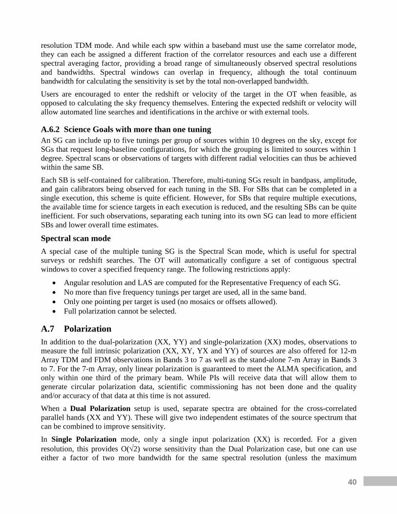
40
resolution TDM mode. And while each spw within a baseband must use the same correlator mode, they can each be assigned a different fraction of the correlator resources and each use a different spectral averaging factor, providing a broad range of simultaneously observed spectral resolutions and bandwidths. Spectral windows can overlap in frequency, although the total continuum bandwidth for calculating the sensitivity is set by the total non-overlapped bandwidth. Users are encouraged to enter the redshift or velocity of the target in the OT when feasible, as opposed to calculating the sky frequency themselves. Entering the expected redshift or velocity will allow automated line searches and identifications in the archive or with external tools.
A.6.2 Science Goals with more than one tuning An SG can include up to five tunings per group of sources within 10 degrees on the sky, except for SGs that request long-baseline configurations, for which the grouping is limited to sources within 1 degree. Spectral scans or observations of targets with different radial velocities can thus be achieved within the same SB. Each SB is self-contained for calibration. Therefore, multi-tuning SGs result in bandpass, amplitude, and gain calibrators being observed for each tuning in the SB. For SBs that can be completed in a single execution, this scheme is quite efficient. However, for SBs that require multiple executions, the available time for science targets in each execution is reduced, and the resulting SBs can be quite inefficient. For such observations, separating each tuning into its own SG can lead to more efficient SBs and lower overall time estimates.
Spectral scan mode A special case of the multiple tuning SG is the Spectral Scan mode, which is useful for spectral surveys or redshift searches. The OT will automatically configure a set of contiguous spectral windows to cover a specified frequency range. The following restrictions apply:
• Angular resolution and LAS are computed for the Representative Frequency of each SG. • No more than five frequency tunings per target are used, all in the same band. • Only one pointing per target is used (no mosaics or offsets allowed). • Full polarization cannot be selected.
A.7 Polarization In addition to the dual-polarization (XX, YY) and single-polarization (XX) modes, observations to measure the full intrinsic polarization (XX, XY, YX and YY) of sources are also offered for 12-m Array TDM and FDM observations in Bands 3 to 7 as well as the stand-alone 7-m Array in Bands 3 to 7. For the 7-m Array, only linear polarization is guaranteed to meet the ALMA specification, and only within one third of the primary beam. While PIs will receive data that will allow them to generate circular polarization data, scientific commissioning has not been done and the quality and/or accuracy of that data at this time is not assured. When a Dual Polarization setup is used, separate spectra are obtained for the cross-correlated parallel hands (XX and YY). These will give two independent estimates of the source spectrum that can be combined to improve sensitivity. In Single Polarization mode, only a single input polarization (XX) is recorded. For a given resolution, this provides O(√2) worse sensitivity than the Dual Polarization case, but one can use either a factor of two more bandwidth for the same spectral resolution (unless the maximum
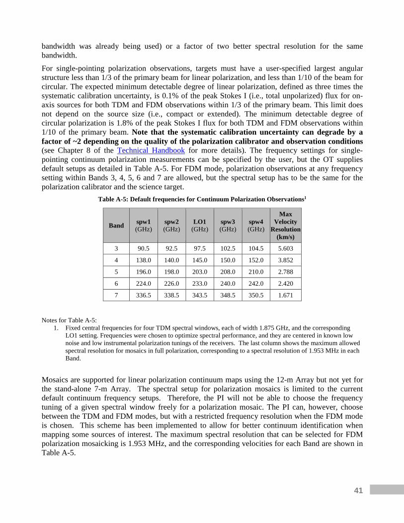
41
bandwidth was already being used) or a factor of two better spectral resolution for the same bandwidth. For single-pointing polarization observations, targets must have a user-specified largest angular structure less than 1/3 of the primary beam for linear polarization, and less than 1/10 of the beam for circular. The expected minimum detectable degree of linear polarization, defined as three times the systematic calibration uncertainty, is 0.1% of the peak Stokes I (i.e., total unpolarized) flux for on-axis sources for both TDM and FDM observations within 1/3 of the primary beam. This limit does not depend on the source size (i.e., compact or extended). The minimum detectable degree of circular polarization is 1.8% of the peak Stokes I flux for both TDM and FDM observations within 1/10 of the primary beam. Note that the systematic calibration uncertainty can degrade by a factor of ~2 depending on the quality of the polarization calibrator and observation conditions (see Chapter 8 of the Technical Handbook for more details). The frequency settings for single-pointing continuum polarization measurements can be specified by the user, but the OT supplies default setups as detailed in Table A-5. For FDM mode, polarization observations at any frequency setting within Bands 3, 4, 5, 6 and 7 are allowed, but the spectral setup has to be the same for the polarization calibrator and the science target.
Table A-5: Default frequencies for Continuum Polarization Observations1
Band spw1 (GHz)
spw2 (GHz)
LO1 (GHz)
spw3 (GHz)
spw4 (GHz)
Max Velocity
Resolution (km/s)
3 90.5 92.5 97.5 102.5 104.5 5.603
4 138.0 140.0 145.0 150.0 152.0 3.852
5 196.0 198.0 203.0 208.0 210.0 2.788
6 224.0 226.0 233.0 240.0 242.0 2.420
7 336.5 338.5 343.5 348.5 350.5 1.671 Notes for Table A-5:
1. Fixed central frequencies for four TDM spectral windows, each of width 1.875 GHz, and the corresponding LO1 setting. Frequencies were chosen to optimize spectral performance, and they are centered in known low noise and low instrumental polarization tunings of the receivers. The last column shows the maximum allowed spectral resolution for mosaics in full polarization, corresponding to a spectral resolution of 1.953 MHz in each Band.
Mosaics are supported for linear polarization continuum maps using the 12-m Array but not yet for the stand-alone 7-m Array. The spectral setup for polarization mosaics is limited to the current default continuum frequency setups. Therefore, the PI will not be able to choose the frequency tuning of a given spectral window freely for a polarization mosaic. The PI can, however, choose between the TDM and FDM modes, but with a restricted frequency resolution when the FDM mode is chosen. This scheme has been implemented to allow for better continuum identification when mapping some sources of interest. The maximum spectral resolution that can be selected for FDM polarization mosaicking is 1.953 MHz, and the corresponding velocities for each Band are shown in Table A-5.
42
For linear polarization mosaics, the 150-point restriction per SG remains in place. The mosaic pattern can be arbitrary, but ALMA recommends a hexagonal grid when possible. While Nyquist sampling (half a beam overlap) is sufficient, a sampling sparser than Nyquist (i.e., a more “loosely packed” mosaic) must be justified. A proposal requesting a mosaic sampling rate sparser than Nyquist may be rejected on technical grounds. The average error estimates for linear polarization mosaics are 1 degree in polarization position angle, and 0.1% in polarization fraction in the regions of the mosaic that correspond to the inner 1/3 FWHM of a given pointing. Near the FWHM of a given pointing, the estimated upper limits are 4 degrees and 0.5% (see Chapter 8 of the Technical Handbook for details).
A.8 Source restrictions Source positions are designated by: 1) fixed RA and DEC; 2) RA and DEC at epoch 2000.0 with a linear proper motion; or 3) an ephemeris that gives the RA and DEC as a function of time. All positions should be in ICRS (J2000). At low elevations, it is possible for foreground array elements to block or “shadow” the signal received by background antennas, compromising the sensitivity and imaging characteristics of an observation (see Section 7.3 of the Technical Handbook for details). Therefore, observations of extremely high and low declination targets should be avoided, particularly in compact configurations. For the 12-m Array, this shadowing becomes significant (> 5%) in the most compact configuration for sources with declinations lower than −65° or higher than +20°. For the ACA, shadowing becomes significant for sources with declinations lower than -70° or higher than +25°. The adopted upper declination limit for ALMA is ~+47°, corresponding to a maximum elevation of 20 degrees at the ALMA site. The OT gives a warning for objects at ~+37-47° declination, corresponding to transits between 20- and 30-degrees elevation. The ALMA Sensitivity Calculator takes shadowing into account when determining time estimates.
A.8.1 Source Science Goal restrictions A single SG is constrained to include one set of observational parameters that apply to all sources included in that goal. This includes a single angular resolution, sensitivity, LAS, and receiver band. There is no restriction on the number of SGs per proposal. For sources distributed widely in the sky the SG will be split by the OT into different “clusters”, each grouping all sources within 10 degrees (1 degree for SGs requiring long-baseline configurations). For each grouping within the SG, the total number of pointings must be less than or equal to 150. Pointings with the ACA, if used in concert with 12-m Array observations, do not count against this 150-pointing limit. The sources in a SG are further subjected to the following restrictions:
• All the sources in a SG must be defined by the same field setup – either all as rectangular fields, or all as individual positions.
• Sources must use the same spectral setup (relative placement and properties of spectral windows).
• For a given group of sources clustered within 10 degrees on the sky (or 1 degree for long-baseline configurations), there cannot be more than 5 separate tunings.
43
A.8.2 Rectangular field A rectangular field (also referred to as a mosaic) is specified by a field center, the length, width and orientation of the field, and a single spacing between the pointing centers. Observations are conducted using the “mosaic” observing mode. This mode repeatedly cycles through all the pointings in the mosaic so that the imaging characteristics across the map are similar. The OT will set up a uniform mosaic pattern based on a user-specified pointing separation, and will calculate the time to reach the required sensitivity considering any overlap. Non-Nyquist spatial samplings are allowed but must be justified in the Technical Justification. If ACA observations are requested as part of a mosaic, then a corresponding 7-m Array mosaic will also be observed. If these include TP observations, the mosaic area(s) will be covered by the TP Array using on-the-fly mapping. An SG may include multiple sources, each of which can have a differently sized rectangular field. The collection of mosaics is subject to the source SG restrictions given above.
A.8.3 Individual pointings PIs may choose to define a “custom mosaic” by specifying a set of individual, overlapping pointing positions. Gaps in pointings are not allowed. Custom mosaics are subject to all the source SG restrictions given above. The interferometric data will be combined in post-processing to produce a single image. If ACA observations are requested as part of a 12-m Array SG, then the corresponding 7-m Array observations will be obtained using a Nyquist-sampled mosaic pattern that covers the 12-m Array pointings. If these include TP observations, the mosaic area(s) will be covered by the TP Array using on-the-fly mapping. Pointings that do not overlap within a given SG must be included as different field sources within the SG.
A.9 Calibration The ALMA Observatory has adopted a set of strategies to achieve good calibration of the data (see Chapter 10 of the Technical Handbook). Requests for changes in these strategies will only be granted in exceptional circumstances and must be fully justified. The default option is automatic calibrator selection by the system at observing time, but some flexibility exists in choosing the actual calibrator sources in the OT. User-selected calibrators must be justified as they may result in decreased observing efficiency and/or calibration accuracy.
A.9.1 Imaging dynamic range The standard ALMA data reduction with nominal phase stability should be sufficient to produce images with dynamic ranges (peak continuum flux to map rms) up to ~100 for the ACA and for compact 12-m Array configurations. For configurations more extended than 2 km and at frequency Bands 8, 9, and 10, the imaging dynamic range may be closer to 50. Images of bright sources may be dynamic-range-limited rather than sensitivity-limited. Their image quality may be improved with self-calibration. For more information please see the Knowledgebase article “What is meant by imaging dynamic range?” and Section 10.5.1 of the Technical Handbook.
44
A.9.2 Absolute flux accuracy Absolute amplitude calibration will be based on observations of objects of known flux density, including eight Solar System objects and a set of 40 quasars whose flux densities are monitored every 15 days. It is expected that these calibrators provide an absolute flux accuracy better than 5% for Bands 3, 4 and 5; 10% for Bands 6, 7 and 8; and 20% for Bands 9 and 10. The decrease in accuracy at the higher frequencies is caused by variable atmospheric opacity, pointing errors, and coherence loss due to phase fluctuations.
A.9.3 Bandpass accuracy The amplitude and phase shape of the spectral response for each antenna in the array is measured by observing a bright source, usually a quasar, for the time needed to reach the desired spectral sensitivity for the relevant spectral resolution. The accuracy of this shape particularly affects projects that intend to observe spectral features that cover a significant fraction of a spectral window, and/or study faint spectral features in the presence of strong continuum. A spectral dynamic range (i.e., the desired signal-to-noise ratio per spectral resolution element) of 1000 has been demonstrated for Bands 3, 4, and 6, and a spectral dynamic range of 400, 250, 170, and 150 has been demonstrated for Bands 7, 8, 9, and 10, respectively. For Band 5, a limit similar to Band 6 may be assumed, except for setups near the 183 GHz atmospheric absorption line. The achieved spectral dynamic range will depend on the brightness of the bandpass calibrator, the observing frequency, and spectral resolution (see Section 10.4.6 of the Technical Handbook for details). Proposals that request higher accuracies need to provide a feasible calibration strategy in the Technical Justification or the proposal may be rejected on technical grounds.
A.9.4 Total Power calibration The intensity calibration for single-dish observations with the TP Array is made by using the Amplitude Calibration Device (ACD), which results in an intensity scale in terms of the corrected Rayleigh-Jeans antenna temperature TA
* (K). To combine the TP data with the interferometric data, the intensity scale is converted from K to Jy. The conversion factor is a function of the observed frequency, half-power beam width, and aperture efficiency of the TP Array antennas. The latter two are derived from regular single-dish calibration observations. The overall accuracy for the total power calibration is about 5% at Bands 3 to 7, increasing to 15% at Band 8.
A.9.5 Astrometry
The absolute positional registration of an ALMA image on the sky depends on the angular resolution and the quality of the phase calibration. With a stable atmosphere, a calibrator-target separation of less than about four degrees, and a signal-to-noise ratio of the target image >20, the nominal accuracy of the position measurement (standard deviation) is 5% of the synthesized beam for angular resolutions >150 mas. At higher angular resolutions of ~50 mas, the best astrometric accuracy decreases to 10% of the synthesized beam. If the astrometric goals are within these ranges, then the observing schedule, observations, and data reduction will be similar to a standard imaging proposal and will be the same as in previous cycles. In Cycle 8 2021, this option now appears explicitly in the ALMA OT as a button labeled “Standard positional accuracy (default)” (see Section “a” below) in a new “Astrometry” panel in the Calibration Setup editor.
The “Enhanced positional accuracy” option (Section “b” below), meanwhile, applies to astrometric projects in which the main scientific goals include measuring the celestial position of the science

45
target to better than the nominal expectation, or measuring the position change of a target over a period of hours to years in a multi-epoch experiment.
To reach the desired astrometric accuracy, the optimum choices of the observing frequency, configuration, and time on target will depend on the properties of the target (spectrum, angular size, brightness) and should be chosen by the PI (see Section "a" below). Note that configurations C-9 and C-10 will not be available in Cycle 8 2021. Proposers of astrometric-type projects with the science goal of measuring a source's position are also encouraged to seek help via the Helpdesk.
In the ALMA OT, the editor panel referring to the positional accuracy can be found in the Calibration Setup editor. The default “Standard positional accuracy (default)” option provides the same default calibration strategy as in previous cycles.
a. Standard positional accuracy (default): The choice of observing frequencies and configurations will depend on the science goal and source properties (see more details in the Technical Handbook, Chapter 10). Many previous astrometric programs requiring high precision have used Band 6 or 7 with configurations similar to C-5, C-6, or C-7, since these combinations are more commonly scheduled than higher frequencies and longer baselines. Note that increasing the S/N of the image peak intensity above 20 will not significantly improve the astrometric accuracy. For lower values (<20), consider the equation in the Astrometry section of Chapter 10 of the Technical Handbook, but a minimum S/N of 15 is recommended.
b. Enhanced positional accuracy: An astrometric proposal should select the “enhanced” option in the Calibration Setup if (1) significantly better than nominal astrometric accuracy (e.g., 3%) is needed, or (2) multi-epoch observations over weeks or months are requested, so the choice of configurations is not straightforward. In these cases, the PI should contact ALMA staff through the Helpdesk. The reason for selecting the “enhanced” option must be justified in the Technical Justification (see Section B.4).
For Cycle 8 2021, the PI should contact ALMA staff via the Helpdesk concerning the possible choices of phase calibrators and the choices of configurations and observation dates for longer-term multi-epoch observations. Experienced PIs may use the “User-defined calibration” option to request the use of multiple or specific calibrators. Nevertheless, while doing so, the PI is requested to select the “Enhanced positional accuracy” and, again, to double check the strategy with ALMA staff via the Helpdesk. The proposed strategy must be described in the Technical Justification.
A.10 Time-constrained observations Monitoring observations and time-constrained projects are offered subject to the following restrictions:
• Observations to be performed with two 12-m Array configurations to satisfy the PI requests of AR and LAS within a SG are not allowed to have time constraints.
• Observations with one 12-m Array configuration and the ACA are allowed to have time constraints only if simultaneous observations with the two arrays have been requested.
• No restrictions will be imposed on the size of the time window specified by PIs for time-critical observations. The scheduling feasibility of any proposal will depend on the total number of constraints that are imposed and on whether the time window takes place during
46
other activities on the array such as engineering or computing time. Whether such observations are technically feasible will be decided on a case-by-case basis. In particular, observations with strict timing constraints but many possible time windows may be feasible.
• Programs that require more than two hours of continuous observations to monitor a source cannot be guaranteed due to variable weather conditions and system interruptions. Proposers may request monitoring observations longer than two hours, but if the observations fail after two hours, the observations will not be repeated. Monitoring observations will be interrupted by regular calibrations. Investigators should contact their ARC through the Helpdesk for support on such observations.
Stand-alone ACA proposals requesting only observations on the 7-m Array are allowed to have time constraints.
A.11 Solar observations Proposals will be accepted for ALMA interferometric and Total Power observations of the Sun with the following capabilities and restrictions:
• Solar observations will be conducted only during the periods when the 12-m Array is in one of the allowed configurations for the requested band, namely C-1 to C-4 for Band 3, C-1 to C-3 for Band 5, C-1 to C-3 for Band 6, and C-1 to C-2 for Band 7 (see configuration schedule in Section 4.3.3).
• The interferometric component of Solar observations will be conducted using a special combined array comprising both 12-m and 7-m antennas (to ensure sufficient short-spacing information is observed), and will be processed with the 64-input Correlator (Section 5.1 of the Technical Handbook). Observations with only the 12-m Array or only the 7-m Array are not offered.
• To minimize shadowing of 7-m antennas, observations will be carried out between 10:00 and 17:00 CLT (13:00 UT and 20:00 UT).
• PIs may designate a desired range of angular resolutions. This is restricted to the range provided by the 12-m configurations allowed for Bands 3, 5, 6, and 7, as described above.
• The Total Power component of Solar observations consists of fast-scanning mapping observations of the full Sun to recover the largest angular scales for interferometric observations. Proposals requesting only Total Power single-dish observations will not be accepted. The Total Power observations will be taken contemporaneously with the interferometric observation. These observations will not be executed when the Sun is at elevations above 70⁰ because the required fast-scan azimuth slew speeds are too high. The time cadence of full-sun images obtained from Total Power observations is about 10, 13, 15 and 25 minutes for Bands 3, 5, 6, and 7, respectively.
• Proposers will specify their Solar target by providing a target position in Heliocentric coordinates. The ALMA Observatory will coordinate with successful PIs to get an updated target position at least 24 hours in advance of the proposed observation. The interaction will be done via the Helpdesk. The ALMA Solar Ephemeris Generator tool is available for PIs to help them generate the ephemeris.
• Only proposals for continuum observations in Bands 3, 5, 6 and 7 will be accepted. For interferometric observations, these will be obtained using the low spectral resolution (TDM)
47
mode (see Section A.6.1). The individual integration times for this mode are fixed to 1 second, and the frequencies are fixed to four 1875 MHz-wide spectral windows centered on the frequencies shown in Table A-6. The high spectral resolution (FDM) observing mode is not offered for Solar observations.
• The observing frequencies of the Total Power observations are as shown in Table A-6, but the Total Power data only include one channel per spw; a correlator will not be used for Total Power observations so autocorrelation measurements will not be available.
Table A-6: Observing frequencies for Cycle 8 2021 Solar observations
Band spw1 (GHz)
spw2 (GHz)
LO1 (GHz)
spw3 (GHz)
spw4 (GHz)
3 93.0 95.0 100.0 105.0 107.0
5 191.0 193.0 198.0 203.0 205.0
6 230.0 232.0 239.0 246.0 248.0
7 339.6 341.6 346.6 351.6 353.6
• Simultaneous observations with Bands 3, 5, 6 and 7 are not offered: each Science Goal can
only include one band.
• Observations may be performed using dual linear polarization (XX, YY) or single polarization (XX) correlations; full polarization measurements are not currently offered for Solar observations.
• Because the WVR receivers are saturated when the antennas point at the Sun, WVR corrections for on-source (Solar) data are not possible.
• Absolute calibration of single-dish brightness temperatures is currently no better than ~10% but is more realistically ~15%. While efforts are on-going to improve Solar calibration, Science Goals that require absolute temperatures more accurate than this, and in particular comparisons of absolute temperatures between Bands 3, 5, 6 and 7, will be difficult to carry out successfully.
A.12 VLBI observations Proposals will be accepted for VLBI observations that use ALMA as a phased array, with the following capabilities and restrictions:
• VLBI observations will be conducted using a “campaign mode”, whereby specific dates are reserved for the execution of VLBI programs in coordination with the other facilities in the VLBI network and so that VLBI experts are available to help with program execution. Observing windows will be identified during the periods when the 12-m Array is in one of the three most compact configurations (with maximum baselines ≤500 m; see configuration schedule in Section 4.3.3). The actual campaign dates will be set after the proposal review process.
• New to Cycle 8 2021, VLBI observations will be permitted for science targets with correlated flux densities < 0.5 Jy through use of a passive phasing mode. The user must select a bright

48
(>0.5 Jy) phase calibrator (phasor), ideally within 6 or 3 degrees of the science target in Band 3 or 6, respectively. The user-defined calibrator interface is enforced for passive phasing and the default dynamic phase calibrator should be replaced with a fixed calibrator (see Section B.6.1). The choice of calibrator should be justified in the Technical Justification.
• Typical passive phasing observing sequences will consist of a short (~1–3 min) VLBI scan on the phasor, immediately followed by a longer scan on the science target itself (up to ~5 min).
• VLBI proposals will only be accepted for continuum observations in Bands 3 and 6. These will be obtained in full polarization using the FDM mode (see Section A.6.1) and the 64-input Correlator. Observing frequencies are fixed to four 1875 MHz-wide spectral windows centered on the frequencies shown in Table A-7 below.
Table A-7: Observing Frequencies for Cycle 8 2021 VLBI Observations
Band spw1 (GHz)
spw2 (GHz)
LO1 (GHz)
spw3 (GHz)
spw4 (GHz)
3 86.268 88.268 93.268 98.268 100.268
6 213.1 215.1 222.1 227.1 229.1
• The proposers are required to enter a VLBI total time requested. Here, they should enter the amount of time requested for ALMA (and not the total time requested to the GMVA/EHT networks, which may be longer). Note that this time must include overheads. For ALMA + GMVA or EHT the total observing time (including overheads and ALMA calibrations) is a factor of four (25% duty cycle) of the expected time on source.
• ALMA’s VLBI observing window in a given cycle will not exceed two weeks, so if multi-epoch observations are requested, they must fit within that time frame and the total time request must be the aggregate time of all observations.
• GMVA and EHT sites record data on a circular polarization basis, while ALMA records linear polarization products. A minimum of three observing hours is required to make an accurate linear to circular polarization transformation of the ALMA VLBI data.
For 3-mm VLBI, a proposal must have been submitted to the GMVA network by their 1 February 2021 deadline (see the GMVA website that also provides a sensitivity calculator). Another sensitivity calculator is available at the European VLBI Network site. For 1.3-mm VLBI, the ALMA Observatory will forward the submitted proposals to the EHT network for technical assessment. Thus, proposers do not need to send their proposal to the EHT directly.
A.13 Phased Array observations In previous cycles the data produced by ALMA in phased-array mode has been used only in combination with data from other telescopes for VLBI observations. Starting with Cycle 8 2021, the 12-m ALMA dishes may also be used as a stand-alone phased array for pulsar science in Band 3. As these are ALMA-only observations, a copy of the proposal should not be sent to the GMVA.
• This mode is available by selecting the Phased Array proposal type. In Cycle 8 2021, only pulsar-science projects will be accepted for this mode, so the PI should select the scientific
49
keyword “Pulsars and neutron stars” in the scientific category “Stellar Evolution and the Sun”. The proposal code will have the “.P” suffix.
• The capabilities are similar to those currently available for VLBI, i.e., a single source per Science Goal with a maximum-bandwidth, pseudo-single-continuum spectral setup, but only Band 3 is available. The spectral window frequencies are the same as those used for VLBI.
• As in standard VLBI modes, VLBI recordings of the phased sum signal are made while the ALMA interferometric data are archived in parallel.
• Since this mode is only for pulsar observations, passive phasing (see A.12) is enforced by the OT as these sources are very weak at mm/sub-mm wavelengths. A fixed phase calibrator will need to be selected and justified (see Section B.6.1)
• Typical passive phasing observing sequences will consist of a short (~1–3 min) VLBI scan on the phasor, immediately followed by a longer scan on the science target itself (up to ~5 min).
• The phased-array data from all four available basebands (derived from the VLBI recordings) will be made available to the PI in PSRFITS format.
• Observations using this mode will be scheduled during the time periods assigned for VLBI. • As for VLBI proposals, the total array time required by each Science Goal must be provided
(see Section B.7). This should be set to a minimum of 3 hours to allow for proper polarization calibration. The requested array time should be justified in the box entitled “Phased Array Technical Justification including Post-Processing”.
• Contact your ARC through the Helpdesk for additional assistance in planning observations with this mode.

50
Appendix B Technical Justification guidelines The Technical Justification must be entered directly into the OT for each Science Goal. Below are guidelines on issues to consider in the different sections. Sections B.5, B.6, and B.7 point to specific items that need justification for Solar, VLBI, and pulsar observations, respectively. In general, PIs should address all the parameters requested in the OT.
B.1 Sensitivity At the top of the sensitivity section, the OT will display the calculated sensitivity and S/N ratio achieved for different bandwidths (bandwidth requested for sensitivity, aggregate bandwidth, a third of the linewidth) as appropriate for the spectral setup and the defined Expected Source Properties. While the justification for the requested sensitivity or S/N ratio should be included in the Scientific Justification (Section 5.3.2), the TJ must explain which sensitivity or S/N ratio are expected for all the parts of the spectrum that are of interest, e.g., for a spectral setup targeting a weak and a strong spectral line as well as the continuum, and the means by which the proposed technical setup will achieve those requests. The fluxes in the Expected Source Properties must be entered per synthesized beam; i.e., proposers may have to correct any available flux measurements for the fact that the requested source is spatially resolved by ALMA and the flux is distributed over several synthesized beams (see Knowledgebase articles “How can I estimate the Peak Flux Density per synthesised beam using flux measurements in Jy or K from other observatories?” and “How do I convert flux measurements given in Jy km/s or K km/s into the peak flux density required by the OT?” and this video for more details on using fluxes/brightness temperatures from other facilities). Users should be aware that the sensitivity requested may not be achievable in practice if the observations are dynamic-range limited; e.g., when the field of view contains another, very bright, source or the spectrum has very bright lines. S/N values smaller than three trigger a blue informative message and need to be fully justified; they may lead to a rejection of the proposal on technical grounds if no adequate explanation is given. For setups including spectral lines, another value to double-check is the ratio of the linewidth (entered in the Expected Source Properties) over the bandwidth used for sensitivity (from the Control & Performance editor), which is conveniently displayed by the OT. It is important to understand that the sensitivity requested will be achieved over a frequency bin corresponding to this bandwidth, not necessarily over every spectral resolution element. For spectral-line measurements this value should normally be larger than three (or even higher if you want to measure the shape of the line profile). An informative message will appear if this is not the case, and PIs should address this issue in the justification text (e.g., if the sensitivity requirement is driven by the continuum it may be acceptable to have a very low ratio). The final parameter to be checked for observations measuring both line and continuum emission is the spectral dynamic range, defined as the continuum peak flux divided by the line rms. Limits on the spectral dynamic ranges offered in Cycle 8 2021 for the different ALMA bands are given in Appendix A (Section A.9.3); an informative message will appear in the OT if these are exceeded and the proposal may be rejected on technical grounds unless justified. The spectral dynamic range is important especially when trying to detect a weak line on top of a strong continuum, and high spectral dynamic ranges may require a better bandpass accuracy than possible with a standard calibration. If a high spectral dynamic range is required, extra bandpass calibrations may need to be obtained selecting “User-defined calibration”.
51
B.2 Imaging When planning ALMA observations, in addition to the sensitivity goals, the complexity of the emission in the science target field should also be considered. An interferometer's ability to reconstruct complex emission is directly related to the uv-coverage of the data. This section is used to justify the requested AR and LAS, which for convenience are reported back by the OT. The AR and LAS needed to image complex emission should be carefully justified (if necessary, including simulations), especially if multiple antenna configurations are required. The number of required antenna configurations is listed in the observing time estimate of the project time summary in the OT. The “snapshot” (i.e. short observation) uv-coverage is excellent for the compact ALMA configurations C-1 to C-3 and still reasonably good for C-4 to C-6, but for the longer baseline configurations, C-7 to C-10, it is quite sparse even with 50 antennas (see Section 7.5 of the Technical Handbook). Therefore, more observing time must be spent to “fill in” the missing uv-coverage, as much as possible. Thus, high fidelity imaging of complex and/or high dynamic range emission may require a longer observing time than implied by sensitivity requirements alone, and this is especially true for the long-baseline configurations. Consecutive executions of a given SB (if needed) are favored during scheduling to maximize uv-coverage. Nonetheless, if more extensive uv-coverage is required to satisfy the imaging requirements, the OT's sensitivity-based time estimate can be overridden (see below). PIs are strongly encouraged to use the ALMA simulator tools to assess the potential need for extra uv-coverage. For the 7-m Array, integrations of at least one hour are recommended to achieve good image quality. For single or non-overlapping pointings, the source should fit within the inner one third of the primary beam (field of view), or the PI should discuss the effects of the sensitivity loss towards the beam edges. PIs should also pay attention to the expected image dynamic range (see Section A.9.1) if attempting to detect a weak signal that falls in the same pointing as a much brighter source. The OT cannot identify such cases automatically since it has no knowledge of the flux structure of the field to be observed. See the Knowledgebase article “What is meant by imaging dynamic range?” for details.
B.3 Correlator configuration For spectral-line observations, the OT reports the number of (Hanning smoothed) spectral resolution elements per linewidth, taking into account any spectral averaging, and the width of the representative spectral window. PIs have to make sure to select the correct representative spectral window. If the spectral resolution is larger than one third of the linewidth from the Expected Source Properties, an informative message will appear, and if not suitably justified this will lead to the rejection of the proposal on technical grounds. Note that the spectral resolution is not necessarily the same as the bandwidth for sensitivity. The requested correlator setup and the placement of spectral windows should be carefully justified in the free-format text box. In the case of multiple spectral lines and/or narrow spectral windows in particular, PIs should double-check that the line profiles are fully covered by the selected spectral windows. PIs should also check whether any of the spectral windows are severely impacted by atmospheric absorption, which can affect Bands 5 and 7 to 10 especially. If necessary, the representative frequency should be modified to be at the most restrictive part of the atmosphere where a line needs
52
to be detected, thus impacting the time estimate. Any continuum windows should be moved to avoid areas of bad transmission. For the double sideband receivers (Bands 9 and 10), the atmospheric transmission in the mirrored spectral window due to the 90-degree Walsh Switching (Section A.5) impacts the sensitivity achieved in the spectral window and therefore the time estimate. PIs may wish to modify the spectral setup accordingly. The best practice for good calibration is to add continuum spectral windows in any unused basebands, in particular for high-frequency SGs. The Phase 2 Group assigned to the project can add these windows, if needed. For sources with known high line density (~1 spectral feature per 10 MHz), PIs are particularly encouraged to set up all the spectral windows in FDM mode. This will allow a more robust determination of the line-free channels used to form the aggregate continuum during data processing and imaging.
B.4 Choices to be justified The OT will automatically catch a number of user choices that must be explicitly justified in a text box. These choices are:
• Override of OT's sensitivity-based time estimate: Proposers may wish to override the OT's time estimate to monitor a source over a certain time range or to build up the uv-coverage for imaging a complex source. When using this option, proposers should keep in mind that programs that require more than two hours of continuous observations cannot be guaranteed due to variable weather conditions and system interruptions (Section A.10). The time entered refers to that of the largest array requested, includes all calibrations, and must be fully justified. Note that the OT assigns the PWV based on the representative frequency of the requested observations and the declination of the source to ensure data quality. Thus, it is not possible to request specific weather conditions for the observations.
• Time-constrained observations: the OT allows you to specify two types of time-constrained observing: single visit and multiple visits. In the first case, one or more time windows are specified, but the observations will only be carried out once during any of these time windows. In the second case, the Science Goal is observed in each of the time windows specified. The technical feasibility of time-constrained observations will be decided on a case-by-case basis.
• User-defined calibration: the default system-defined calibration option ensures that the proper calibrations for the flux scale, bandpass, and relative antenna gains are obtained. Observations making use of the full polarization capabilities of ALMA will also include the necessary calibrations by default. User-defined calibrations should be necessary only in rare cases, e.g., if a very high spectral dynamic range is required, it may be necessary to perform additional calibrations and/or use specific sources. Such requests must be explained and justified in detail. Programs that cannot be calibrated or that significantly increase the complexity of data reduction will not be allowed and will be flagged as technically infeasible and rejected.
• Low maximum elevation: sources that transit at a low elevation are difficult to schedule for observation since they suffer from high atmospheric attenuation and require low PWV, especially at high frequencies (see Section A.8). A detailed explanation should be provided as to why these sources need to be observed rather than sources at higher elevation.

53
• Single polarization: this should only be used when the highest spectral resolution is required, as the sensitivity achieved is lower than when using the default dual polarization. PIs should carefully justify why the high spectral resolution requested is required.
• Sparser sampling than the default λ/√3D (Nyquist sampling) can be more effective at covering large areas more quickly, at the price of less uniform spatial coverage and noise. Deviating from the default mosaic sampling must be justified scientifically, and is to be avoided when imaging extended sources, particularly if image fidelity is an important concern.
• Enhanced positional accuracy: this option should be selected when an accuracy better than nominal is required (see Section A.9.5). In the corresponding Technical Justification section, the PI must justify the need for the enhanced positional accuracy and give any further details that may have been advised by ALMA staff through the Helpdesk.
B.5 Solar observations The sensitivity calculator is not adequate for Solar observations because the antenna temperature greatly exceeds the system temperature and, moreover, depends on the Solar target (e.g., quiet Sun, active region, Solar limb). Therefore, Solar proposers are asked to enter the total time and justify this request to the extent that depends on technical imaging considerations, not on scientific factors. For example, for a mosaic of a target in a given frequency band, PIs should indicate how many repetitions of the sampling pattern are needed and why. For this calculation PIs should take into account that ALMA observations are comprised of one or more executions of a SB. The total execution time of an SB cannot exceed 2 hours, which will include the time overheads for bandpass and flux calibration. These calibration overheads amount to about 25 mins.
B.6 VLBI observations The VLBI Technical Justification should be tuned to the overall science goals. As a guideline, the ALMA Technical Justification should include the reasons for using the 1.3- or 3-mm bands, the flux density of the target on a 1 km baseline, correlated flux densities on baselines longer than 5000 km, the total observing time requested (including time for calibration), and potential bandpass, polarization and delay calibrators. If polarimetry is requested, the expected S/N ratio for the polarized emission should be stated. If imaging is requested, imaging considerations should also be mentioned (e.g., dynamic range issues or complex source structure), as well as any other special technical requirements. Finally, the proposers should specify the EHT or GMVA stations that are requested for VLBI. The following online material is currently available to help justify the requested observing time:
• At 3 mm: the sensitivity calculator and the 3 mm VLBI page. • At 1.3 mm: the 1 mm VLBI page.
New to Cycle 8 2021, VLBI targets with correlated flux densities < 0.5 Jy on intra-ALMA baselines out to 1 km may be proposed for observation for both Bands 3 and 6 through use of passive array phasing (see Section A.12). The suitability of the selected fixed phase calibrator must be justified with regards to its flux density and proximity to the VLBI target (a phase calibrator used in this way is termed a “phasor” to avoid confusion with other phase calibrator target usages).

54
There are two ways to search for a phasor candidate: directly from the ALMA OT, or through an initial search on the web-based ALMA Calibrator Source Catalogue. Searching for a phasor source in the ALMA OT When proposing a Phased Array project or VLBI-mode observation of targets fainter than 0.5 Jy on intra-ALMA baselines, the “User-defined calibration” option is triggered in the “Calibration Setup” editor. There, in the “Goal Calibrators” panel, one will see four calibration type entries. To select a phasor source, the PI should follow these steps:
• Select the “Phase” entry and click on “Delete Selected Calibration”;
• Click on “Add Fixed Calibrator”, select “Phase” in the pop-up window, and click “Create”;
• Select “Sidereal Target” and click on “Select from Source Catalogue...”;
• Set the “Radius (º)” value of the “Cone Search” to 6º for Band 3 or 3º for Band 6 (suggested values);
• In “Flux”, set "Min" to 0.5 Jy and click on "Submit Query";
• Ideally, select the entry with the highest “Flux Density”, and with empty “UV Min/Max” columns.
Searching for a phasor source in the ALMA Calibrator Source Catalogue In the “Query Form” tab of the web interface, the RA and DEC information of the target should be entered in the “Position” box. The suggested setting for the search radius is 6º for Band 3 and 3º for Band 6. In the “Energy” box, "Flux Density" should be set to “>0.5”. “Band” should be set to “3” for Band 3 observations or “3,6,7” for Band 6 observations. The reason for the latter is that flux check observations are usually executed in Bands 3 and 7, and less often in Band 6. Hence, to retrieve a more contemporaneous flux value, one can interpolate between Bands 3 and 7 when a Band 6 value is not available. After clicking on the “Search” button, the “Result Table” will provide a list of phasor candidates. In case there is a need to interpolate between Bands 3 and 7 fluxes, the PI can use the “getALMAflux” task from the Analysis Utils (which must be installed within CASA). The PI can also use the “Result Plot” for assessment, where pressing a given data point in the RA/DEC plot on the left-hand side will trigger a light-curve plot to appear on the right-hand side. The PI should then provide the identified source in the “User-defined calibration” option (see above). Be aware that if the flux of the selected phasor decreases below the 0.5 Jy threshold closer to the expected observation execution, an alternative source will have to be found in coordination with the Phase 2 Group.
What if no phasor candidate is found to be brighter than 0.5 Jy? Identified phasor sources will likely be variable, so it is impossible to predict at the time of proposal writing what the flux will be during the observation. As a result, if a given candidate source is fainter than 0.5 Jy at the time of proposal writing, but its light curve (available in the ALMA Calibrator Source Catalogue; see above) shows that it has been brighter in the past or shows a rising flux potentially increasing above the 0.5 Jy threshold, the PI can propose that source as a phasor. In this case, the observatory will check the source's flux closer to the VLBI campaign run and the project will be executed only if the selected source is observed to have a flux greater than 0.5 Jy.
55
What if no phasor candidate is found within the suggested search radius? If the proposed phasor source is farther than 6º from GMVA targets or 3º from EHT targets, there are a few considerations that should be taken into account. The guidelines for angular separation are based on observational conditions during a time of the year (March/April) when VLBI campaigns are usually run. These conditions imply that the phase rms induced by atmospheric turbulence is up to ~25º (84% probability) for the characteristic phasing radius in Band 3 and up to ~45º (84% probability) in Band 6. Assuming a maximum allowed signal decorrelation of 20%, Figure 10.8 in the Technical Handbook suggests the maximum phasor distance of 6º from GMVA targets or 3º from EHT targets. One can now understand that the farther from the target one moves, the higher the signal decorrelation. Although the straightforward way to compensate for a more distant phasor is to integrate longer on the target, there is a limit to how much the QA2 analysis can compensate for this effect (e.g., if the source is too faint to allow self-calibration, or the observing schedule does not allow for a proper solution interpolation between phasor scans). In such extreme cases, the flux calibration will be more uncertain or become erroneous. Considering these issues, the PI can still propose a phasor that is farther way than the guidelines suggest, but it must be justified with regard to how it will not compromise the data quality.
B.7 Phased Array observations The proposer should first read the Phased Array mode sections of the Technical Handbook, paying particular attention to the items in the “Technical Justifications” section at the end. As passive phasing is enforced for this mode, the choice of fixed phase calibrator must be justified. Additional inputs are also required to construct the Scheduling Block and these should be provided in the text box entitled “Phased Array Technical Justification including Post-Processing”:
• Total observing time requested. To cover a sufficient parallactic angle range on the polarization calibrator, typically ~3 hours are required. However, the proposer should indicate how much time is needed on target for the analysis (see below).
• The pulsar period (if known). This value should be provided so that the cadence of the correlator subscans (multiples of 1.008s) does not interfere with the pulsar signal. The time resolution of the PSRFITS file must be a multiple of 8 µs; if lower resolution is adequate, it should be specified to avoid larger than needed PSRFITS files.
• The polarization of the PSRFITS data product. The proposer can select from total intensity, dual polarizations (XX and YY), coherence product, or full Stokes.
Computing the required array time for pulsar observations When in phased-array mode, the digitized voltage signals from each ALMA antenna of the phased array are phase-adjusted and added to provide the recorded phased signal. This process is done for each polarization, and the phased array includes most, but not all, available antennas. This is different from the interferometric signal that results from the correlated voltage signal from each antenna. On top of that, pulsar observations aim to detect the flux of a pulsed signal rather than a continuous one. As a result, neither the sensitivity calculator within the OT nor the web interface provide the correct sensitivity for phased-array pulsar observations. To compute the required total array time for pulsar observations, one should start by computing the time on source (Tint) following the formula in Appendix A1.4 in Handbook of Pulsar Astronomy (Lorimer & Kramer 2004), which we adapt to:

56
Tint [h] = (W/(P-W)) * SEFD2 / (rms2 * Np * Nsp * 1.875E9 * ηeff 2) / 3600 Here, W is the pulse width; P is the pulse period (typical values are W=C*P where C=0.05 to 0.1); SEFD for 37 phased antennas in Band 3 is 67 Jy; rms is the requested sensitivity; Np is the number of polarizations and should be set to 2; Nsp is the requested number of spectral windows; ηeff is the end-to-end passive-phasing efficiency of ~0.74. To estimate the total required observing time on source (including overheads), the user should multiply the computed Tint by three8. The result is the value the PI should provide in the OT. Note, however, that to ensure a proper polarization calibration of the data, the total observing time specified should never be less than 3 hr.
8 This factor is smaller than for the VLBI case since VLBI observations require the observation of specific calibrators that are not needed for pulsar mode.
57
Appendix C Acronyms and abbreviations ACA Atacama Compact Array ACD Amplitude Calibration Device ALMA Atacama Large Millimeter/submillimeter Array AOS Array Operations Site APEX ALMA Pathfinder EXperiment ARC ALMA Regional Center (for EA and NA) or Centre (for EU) ARP ALMA Review Panel APRC ALMA Proposal Review Committee AR Angular Resolution ASC ALMA Sensitivity Calculator ASIAA Academia Sinica Institute of Astronomy and Astrophysics AUI Associated Universities, Inc. CASA Common Astronomy Software Applications Co-I Co-Investigator Co-PI Co-Principal Investigator CONICYT Comisión Nacional de Investigación Científica y Tecnológica CS Contact Scientist DDT Director’s Discretionary Time EA ARC East Asian ALMA Regional Center EHTC Event Horizon Telescope Consortium EPO Education and Public Outreach ESO European Organisation for Astronomical Research in the Southern Hemisphere EU ARC European ALMA Regional Centre FDM Frequency Division Mode FOV Field Of View GMVA Global Millimeter VLBI Array IF Intermediate Frequency KASI Korea Astronomy and Space Science Institute JAO Joint ALMA Observatory LAS Largest Angular Structure LO1 Local Oscillator 1 LSRK Kinematic Local Standard of Rest LST Local Sidereal Time MOST Ministry of Science and Technology in Taiwan MRS Maximum Recoverable Scale NA ARC North American ALMA Regional Center NAASC North American ALMA Science Center NAOJ National Astronomical Observatory of Japan NINS National Institutes of Natural Sciences NRAO National Radio Astronomy Observatory NRC National Research Council of Canada NSC National Science Council of Taiwan NSF National Science Foundation OSF Operation Support Facility OST Observation Support Tool OT Observing Tool OUS ObsUnitSet PDF Portable Document Format PI Principal Investigator PWV Precipitable Water Vapor QA2 Quality Assurance Level 2 SB Scheduling Block
58
SCO Santiago Central Office SG Science Goal S/N Signal-to-noise SnooPI Snooping Project Interface SP Science Portal spw Spectral window TDM Time Division Mode TJ Technical Justification ToO Target of Opportunity TP Total Power VLBI Very Long Baseline Interferometry WVR Water Vapor Radiometer
59
Appendix D Science categories and keywords The list below presents the available science categories and the corresponding keywords that can be used in the OT to further specify the scientific area of the proposal. Proposers must select at least one and at most two keywords. Category 1 – Cosmology and the high redshift universe
a. Lyman Alpha Emitters/Blobs (LAE/LAB) b. Lyman Break Galaxies (LBG) c. Starburst galaxies d. Sub-mm Galaxies (SMG) e. High-z Active Galactic Nuclei (AGN) f. Gravitational lenses g. Damped Lyman Alpha (DLA) systems h. Cosmic Microwave Background (CMB)/Sunyaev-Zel'dovich Effect (SZE) i. Galaxy structure & evolution j. Gamma Ray Bursts (GRB) k. Galaxy Clusters
Category 2 – Galaxies and galactic nuclei
a. Starbursts, star formation b. Active Galactic Nuclei (AGN)/Quasars (QSO) c. Spiral galaxies d. Merging and interacting galaxies e. Surveys of galaxies f. Outflows, jets, feedback g. Early-type galaxies h. Galaxy groups and clusters i. Galaxy chemistry j. Galactic Centers/nuclei k. Dwarf/metal-poor galaxies l. Luminous and Ultra-Luminous Infra-Red Galaxies (LIRG & ULIRG) m. Giant Molecular Clouds (GMC) properties

60
Category 3 – ISM, star formation and astrochemistry a. Outflows, jets and ionized winds b. High-mass star formation c. Intermediate-mass star formation d. Low-mass star formation e. Pre-stellar cores, Infra-Red Dark Clouds (IRDC) f. Astrochemistry g. Inter-Stellar Medium (ISM)/Molecular clouds h. Photon-Dominated Regions (PDR)/X-Ray Dominated Regions (XDR) i. HII regions j. Magellanic Clouds
Category 4 – Circumstellar disks, exoplanets and the solar system
a. Debris disks b. Disks around low-mass stars c. Disks around high-mass stars d. Exoplanets e. Solar system: Comets f. Solar system: Planetary atmospheres g. Solar system: Planetary surfaces h. Solar system: Trans-Neptunian Objects (TNOs) i. Solar system: Asteroids
Category 5 – Stellar evolution and the Sun
a. The Sun b. Main sequence stars c. Asymptotic Giant Branch (AGB) stars d. Post-AGB stars e. Hypergiants f. Evolved stars: Shaping/physical structure g. Evolved stars: Chemistry h. Cataclysmic stars i. Luminous Blue Variables (LBV) j. White dwarfs k. Brown dwarfs l. Supernovae (SN) ejecta m. Pulsars and neutron stars n. Black holes o. Transients
The Atacama Large Millimeter/submillimeter Array (ALMA), an international astronomy facility, is a partnership of the European Organisation for Astronomical Research in the Southern Hemisphere (ESO), the U.S. National Science Foundation (NSF) and the National Institutes of Natural Sciences (NINS) of Japan in cooperation with the Republic of Chile. ALMA is funded by ESO on behalf of its Member States, by NSF in cooperation with the National Research Council of Canada (NRC) and the Ministry of Science and Technology (MOST) in Taiwan and by NINS in cooperation with the Academia Sinica (AS) in Taiwan and the Korea Astronomy and Space Science Institute (KASI). ALMA construction and operations are led by ESO on behalf of its Member States; by the National Radio Astronomy Observatory (NRAO), managed by Associated Universities, Inc. (AUI), on behalf of North America; and by the National Astronomical Observatory of Japan (NAOJ) on behalf of East Asia. The Joint ALMA Observatory (JAO) provides the unified leadership and management of the construction, commissioning and operation of ALMA.