dnvgl-rp-c302 risk based corrosion management
TRANSCRIPT

RECOMMENDED PRACTICE
DNVGL-RP-C302 Edition July 2015
Risk based corrosion management
DNV GL AS
The electronic pdf version of this document found through http://www.dnvgl.com is the officially binding version. The documents are available free of charge in PDF format.

FOREWORD
DNV GL recommended practices contain sound engineering practice and guidance.© DNV GL AS July 2015
Any comments may be sent by e-mail to [email protected]
This service document has been prepared based on available knowledge, technology and/or information at the time of issuance of this document. The use of thisdocument by others than DNV GL is at the user's sole risk. DNV GL does not accept any liability or responsibility for loss or damages resulting from any use ofthis document.

C
hang
es –
cur
rent
CHANGES – CURRENTGeneralThis document supersedes DNV-RP-C302, April 2012.
Text affected by the main changes in this edition is highlighted in red colour. However, if the changes
On 12 September 2013, DNV and GL merged to form DNV GL Group. On 25 November 2013 Det NorskeVeritas AS became the 100% shareholder of Germanischer Lloyd SE, the parent company of the GL Group,and on 27 November 2013 Det Norske Veritas AS, company registration number 945 748 931, changed itsname to DNV GL AS. For further information, see www.dnvgl.com. Any reference in this document to “DetNorske Veritas AS”, “Det Norske Veritas”, “DNV”, “GL”, “Germanischer Lloyd SE”, “GL Group” or any otherlegal entity name or trading name presently owned by the DNV GL Group shall therefore also be considereda reference to “DNV GL AS”.
On 12 September 2013, DNV and GL merged to form DNV GL Group. On 25 November 2013 Det NorskeVeritas AS became the 100% shareholder of Germanischer Lloyd SE, the parent company of the GL Group,and on 27 November 2013 Det Norske Veritas AS, company registration number 945 748 931, changed itsname to DNV GL AS. For further information, see www.dnvgl.com. Any reference in this document to “DetNorske Veritas AS”, “Det Norske Veritas”, “DNV”, “GL”, “Germanischer Lloyd SE”, “GL Group” or any otherlegal entity name or trading name presently owned by the DNV GL Group shall therefore also be considereda reference to “DNV GL AS”.
involve a whole chapter, section or sub-section, normally only the title will be in red colour.
Main changes• GeneralThe revision of this document is part of the DNV GL merger, updating the previous DNV recommended practice into a DNV GL format including updated nomenclature and document reference numbering, e.g.:
— DNV replaced by DNV GL.— DNV-RP-B101 becomes DNVGL-RP-B101 etc.
To complete your understanding, observe that the entire DNV GL update process will be implemented sequentially. Hence, for some of the references, still the legacy DNV documents apply and are explicitly indicated as such, e.g.: Rules for Ships has become DNV Rules for Ships.
In addition to the above stated main changes, editorial corrections may have been made.
Editorial corrections
Recommended practice, DNVGL-RP-C302 – Edition July 2015 Page 3
DNV GL AS

C
onte
nts
CONTENTSCHANGES – CURRENT .................................................................................................. 3
Sec.1 Introduction.................................................................................................. 51.1 Introduction ...........................................................................................51.2 Objective................................................................................................51.3 Scope .....................................................................................................51.4 Structure of document............................................................................61.5 Acronyms ...............................................................................................6
Sec.2 Process description ...................................................................................... 72.1 Introduction ...........................................................................................72.2 Risk management...................................................................................72.3 The 5-step approach...............................................................................9
Sec.3 Step 1 – pre assessment ............................................................................ 113.1 General.................................................................................................113.2 Risk identification for different zones...................................................12
3.2.1 Submerged ................................................................................123.2.2 Splash zone ................................................................................133.2.3 Topside ......................................................................................143.2.4 Tanks and internal structures ........................................................15
Sec.4 Step 2 – screening and risk ranking ............................................................ 174.1 Screening general ................................................................................174.2 Screening for different zones ...............................................................17
4.2.1 Submerged .................................................................................174.2.2 Splash zone ................................................................................174.2.3 Topside ......................................................................................184.2.4 Tanks and other internal structures ................................................18
4.3 Risk ranking ........................................................................................19Sec.5 Step 3 – detailed examination..................................................................... 20
5.1 General.................................................................................................205.2 Coating condition and corrosion assessment .......................................20
5.2.1 Submerged .................................................................................205.2.2 Splash zone ................................................................................205.2.3 Top side .....................................................................................205.2.4 Tanks and internal structures ........................................................20
Sec.6 Step 4 – remediation................................................................................... 226.1 General.................................................................................................226.2 Coatings ...............................................................................................226.3 Cathodic protection .............................................................................236.4 Corrosion monitoring ...........................................................................24
6.4.1 Corrosion coupons .......................................................................246.4.2 Corrosion probes .........................................................................24
6.5 Corrosion inhibition..............................................................................246.6 Bonded patch repair .............................................................................25
Sec.7 Step 5 – life cycle management................................................................... 26
App. A Factors affecting corrosion......................................................................... 28
Recommended practice, DNVGL-RP-C302 – Edition July 2015 Page 4
DNV GL AS

1.1 IntroductionSixty percent (60%) of the world offshore fleet are past their theoretical design age of 20 years. With economic pressure, the rigs are being kept in operation for a prolonged period of time well beyond their design life. Several other rigs are also approaching their 20-year design life.
With aging of the rigs, there is a need to manage material deterioration, i.e. fatigue cracking and corrosion, and to demonstrate to the rig owners and stakeholders the ongoing integrity and safety of those aging rigs.
Existing rules and standards typically address the expected aging effects for a pre-determined design life (time span) at the new build phase. For example corrosion management is covered in:
— DNV GL offshore standards OS-C401, OS-C101, OS-C103, OS-C104, OS-C107 covering corrosion control, and fabrication and installation of corrosion protection systems, i.e. coatings, anodes, and impressed current cathodic protection systems. To name some specific requirements:
— In general, corrosion protection systems should prevent structural deterioration over a rig’s operating life.
— The Rules assume that hard coatings are supplemented by cathodic protection, but alternatives are not excluded.
— The Rules state that the Owner is responsible to maintain the unit in accordance with the design.
— The IMO (Performance Standard for Protective Coatings) Requirement issued on 1st July 2009 states that all ballast tanks must have type approved coatings and a technical file for the coatings to be approved.
However, recent inspection experiences have revealed a number of rigs with severe corrosion, general lack of reporting and poor maintenance, attributed to either a greater deterioration than expected or due to the asset operating for longer than expected.
The above arguments identify the need for a holistic approach on corrosion management during the full operational life of the unit. To be effective, such an approach should ideally take into account extended life and reduce risk of failures and maintenance and inspection cost, at the same time support the continuation of the unit’s operations.
1.2 ObjectiveThis recommended practice (RP) provides a practical risk-based approach to corrosion management based on the principles of ISO 31000 Risk management – Principles and guidelines. The objective of this approach is to improve the cost-effectiveness of corrosion inspection and treatment of offshore vessels in operation, and at the same time reduce the risks of incidents and down time.
The RP will further provide practical guidance and support for the rig superintendent and/or surveyor to inspect and assess the condition of the structure as related to corrosion and corrosion protection.
1.3 ScopeThe risk based corrosion management process and corrosion background given in this document, is relevant for any floating offshore vessel type, i.e. mobile offshore units (MOU), ship shaped, semi-submersible, jack up, and for all different functions, i.e. FPSO, LNG terminal, drilling, etc.
The envisaged users of this RP are foremost, professionals and organizations managing floating offshore -assets (from here indicated as ‘owner’). The RP is relevant for professionals supporting the owner in managing his asset, e.g. design houses, yards and surveyors.
It is emphasized that the document is not intended to provide a detailed description in corrosion and treatment techniques; which are referred to in: DNVGL-RP-B101 Corrosion protection of floating production and storage units, DNV-RP-B401 Cathodic Protection Design and DNVGL-RP-C301 Design, fabrication, operation and qualification of bonded repair of steel structures.
Recommended practice, DNVGL-RP-C302 – Edition July 2015 Page 5
DNV GL AS
require a detailed discussion of organizational principles and framework, which are outside the scope of this document.
1.4 Structure of documentThe main body of this document starts by describing the proposed corrosion management process. This process is introduced by an overview of a risk management process according to ISO 31000, [2.2]. This is followed by the presentation of the practical approach consisting of five different steps described in [2.3].
In the following chapters, each of the five steps is described in more detail followed by a discussion of relevant techniques for the different corrosion zones present on the rig. An example is developed throughout the chapters clarifying the impact of each step from a risk management point of view.
Following the main body of the RP an appendix provides background information on factors affecting corrosion and corrosion protection.
1.5 AcronymsThis section lists the acronyms used in the document.
Table 1-1 Acronyms
Term DefinitionALARP as low as reasonably possibleCP cathodic protectionCVI close visual inspectionFEA finite element analysisFPSO floating production storage and offloadingGVI general visual inspectionICCP induced current cathodic protectionIMO International Maritime OrganizationISO International Organization for StandardizationMIC microbial influenced corrosionMOU mobile offshore unitsNACE National Association of Corrosion EngineersNDT non-destructive testingNPV net present valueOS offshore standardROV remote operating vehicleRP recommended practiceSRBs sulfate reducing bacteriaTTF time to failureTTFF time to first failureUTM ultrasonic thickness measurement
Recommended practice, DNVGL-RP-C302 – Edition July 2015 Page 6
DNV GL AS
2.1 IntroductionThis RP discusses an approach to corrosion management based on risk management principles as defined below.
Figure 2-1 Definition of risk based management
For the purpose of risk-based corrosion management, the above definition translates into a process where the locations with the highest likelihood of coating damage and corrosion, and the highest consequences are identified and selected for detailed inspection and remediation.
In the following two sections, the risk-based corrosion management process is introduced. [2.2] gives an overview of the different process steps based on the ISO 31000 Standard, while [2.3] presents an overview of the practical application of the corrosion management process.
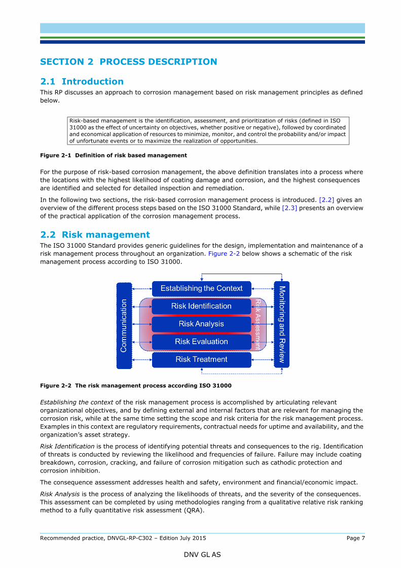
2.2 Risk managementThe ISO 31000 Standard provides generic guidelines for the design, implementation and maintenance of a risk management process throughout an organization. Figure 2-2 below shows a schematic of the risk management process according to ISO 31000.
Figure 2-2 The risk management process according ISO 31000
Establishing the context of the risk management process is accomplished by articulating relevant organizational objectives, and by defining external and internal factors that are relevant for managing the corrosion risk, while at the same time setting the scope and risk criteria for the risk management process. Examples in this context are regulatory requirements, contractual needs for uptime and availability, and the organization’s asset strategy.
Risk Identification is the process of identifying potential threats and consequences to the rig. Identification of threats is conducted by reviewing the likelihood and frequencies of failure. Failure may include coating breakdown, corrosion, cracking, and failure of corrosion mitigation such as cathodic protection and corrosion inhibition.
The consequence assessment addresses health and safety, environment and financial/economic impact.
Risk Analysis is the process of analyzing the likelihoods of threats, and the severity of the consequences. This assessment can be completed by using methodologies ranging from a qualitative relative risk ranking method to a fully quantitative risk assessment (QRA).
Risk-based management is the identification, assessment, and prioritization of risks (defined in ISO 31000 as the effect of uncertainty on objectives, whether positive or negative), followed by coordinated and economical application of resources to minimize, monitor, and control the probability and/or impact of unfortunate events or to maximize the realization of opportunities.
Recommended practice, DNVGL-RP-C302 – Edition July 2015 Page 7
DNV GL AS
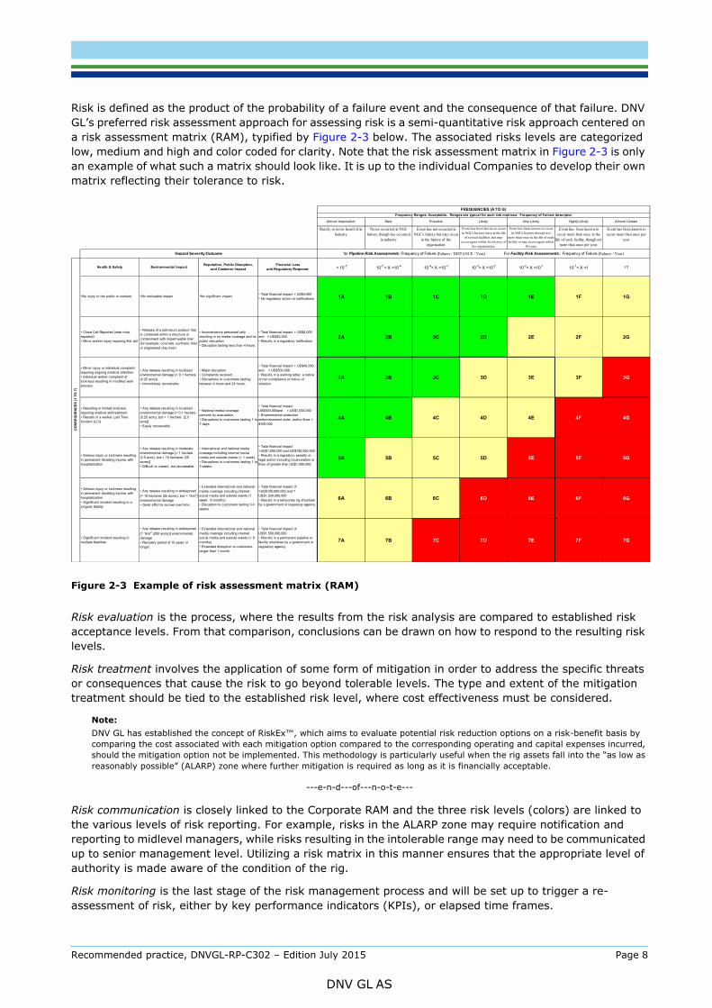
GL’s preferred risk assessment approach for assessing risk is a semi-quantitative risk approach centered on a risk assessment matrix (RAM), typified by Figure 2-3 below. The associated risks levels are categorized low, medium and high and color coded for clarity. Note that the risk assessment matrix in Figure 2-3 is only an example of what such a matrix should look like. It is up to the individual Companies to develop their own matrix reflecting their tolerance to risk.
Figure 2-3 Example of risk assessment matrix (RAM)
Risk evaluation is the process, where the results from the risk analysis are compared to established risk acceptance levels. From that comparison, conclusions can be drawn on how to respond to the resulting risk levels.
Risk treatment involves the application of some form of mitigation in order to address the specific threats or consequences that cause the risk to go beyond tolerable levels. The type and extent of the mitigation treatment should be tied to the established risk level, where cost effectiveness must be considered.
Note:DNV GL has established the concept of RiskEx™, which aims to evaluate potential risk reduction options on a risk-benefit basis by comparing the cost associated with each mitigation option compared to the corresponding operating and capital expenses incurred, should the mitigation option not be implemented. This methodology is particularly useful when the rig assets fall into the “as low as reasonably possible” (ALARP) zone where further mitigation is required as long as it is financially acceptable.
---e-n-d---of---n-o-t-e---
Risk communication is closely linked to the Corporate RAM and the three risk levels (colors) are linked to the various levels of risk reporting. For example, risks in the ALARP zone may require notification and reporting to midlevel managers, while risks resulting in the intolerable range may need to be communicated up to senior management level. Utilizing a risk matrix in this manner ensures that the appropriate level of authority is made aware of the condition of the rig.
Risk monitoring is the last stage of the risk management process and will be set up to trigger a re-assessment of risk, either by key performance indicators (KPIs), or elapsed time frames.
Rarely, or never heard of in Industry
Never occurred in NGC history, though has occurred
in industry
Event has not occurred in NGC's history but may occur
in the history of the organisation.
Event has been known to occur in NGC's history once in the life
of several facilities and may occur again within the history of
the organisation.
Event has been known to occur in NGC's history though not
more than once in the life of each facility or may occur again within
10 years.
Event has been known to occur more than once in the
life of each facility, though not more than once per year.
Event has been known to occur more than once per
year
Health & Safety Environmental ImpactReputation, Public Disruption,
and Customer ImpactFinancial Loss
and Regulatory Response < 10-5 10-5 = X <10-4 10-4= X <10-3 10-3= X <10-2 10-2= X <10-1 10-1= X <1 =1
•No injury to the public or workers •No noticeable impact •No significant impact• Total financial impact = US$4,000• No regulatory action or notifications 1A 1B 1C 1D 1E 1F 1G
• Close Call Reported (near miss reported)• Minor worker injury requiring first aid
• Release of a petroleum product that is contained within a structure or containment with impermeable liner (for example: concrete, synthetic liner, or engineered clay liner)
• Inconvenience personnel only resulting in no media coverage and no public disruption• Disruption lasting less than 4 hours.
• Total financial impact > US$4,000 and = US$40,000.• Results in a regulatory notification
2A 2B 2C 2D 2E 2F 2G
• Minor injury or individual complaint requiring ongoing medical attention• Individual worker complaint of sickness resulting in modified work process
• Any release resulting in localized environmental damage [< 0.1 hectare (0.25 acre)] • Immediately recoverable.
• Major disruption • Complaints received • Disruptions to customers lasting between 4 hours and 24 hours.
• Total financial impact > US$40,000 and = US$500,000.• Results in a warning letter, a notice of non-compliance or notice of violation
3A 3B 3C 3D 3E 3F 3G
• Resulting in limited sickness requiring medical aid/treatment• Results in a worker Lost Time Incident (LCI)
• Any release resulting in localized environmental damage [= 0.1 hectare (0.25 acre), but < 1 hectare (2.5 acre)] • Easily recoverable.
• National media coverage persons by evacuation,• Disruptions to customers lasting 1 to 7 days
• Total financial impact US$500,000and = US$1,000,000• Environmental protection enformecement order, and/or fines < $100,000
4A 4B 4C 4D 4E 4F 4G
• Serious injury or sickness resulting in permanent disabling injuries with hospitalization
• Any release resulting in moderate environmental damage [= 1 hectare (2.5 acre), but < 10 hectares (25 acres)] • Difficult to correct, but recoverable.
• International and national media coverage including internet social media and outside events (< 1 week)• Disruptions to customers lasting 1 to 3 weeks
• Total financial impact >US$1,000,000 and US$150,000,000• Results in a regulatory penalty or legal action including incarceration or fines of greater than US$1,000,000
5A 5B 5C 5D 5E 5F 5G
• Serious injury or sickness resulting in permanent disabling injuries with hospitalization• Significant incident resulting in a singular fatality
• Any release resulting in widespread
[= 10 hectares (25 acres), but < 1km2] environmental damage • Great effort to recover over time.
• Extended international and national media coverage including internet social media and outside events (1 week - 6 months)• Disruption to customers lasting 3-4 weeks
• Total financial impact of >US$150,000,000 and = US$1,500,000,000• Results in a temporary rig shutdown by a government or regulatory agency
6A 6B 6C 6D 6E 6F 6G
• Significant incident resulting in multiple fatalities
• Any release resulting in widespread
[= 1km2 (250 acres)] environmental damage • Recovery period of 10 years or longer.
• Extended international and national media coverage including internet social media and outside events (> 6 months) • Extended disruption to customers longer than 1 month
• Total financial impact of US$1,500,000,000• Results in a permanent pipeline or facility shutdown by a government or regulatory agency.
7A 7B 7C 7D 7E 7F 7G
CO
NS
EQ
UE
NC
ES
(1
TO
7)
Hazard Severity Outcome
Likely
for Pipeline Risk Assessments: Frequency of Failure (Failures / DISTANCE / Year) For Facility Risk Assessments : Frequency of Failure (Failures / Year)
FREQUENCIES (A TO G)Frequency Ranges: Acceptable. Ranges are typical for such risk matrices. Frequency of Failure descriptor
Very Likely Highly Likely Almost CertainAlmost Impossible Rare Possible
Recommended practice, DNVGL-RP-C302 – Edition July 2015 Page 8
DNV GL AS

ISO 31000 underlines that effective implementation requires, besides the above described process, adherence of an organization to a set with principles and an organization framework. These requirements are also applicable for further implementation of the discussed risk-based corrosion management approach. Notwithstanding this applicability, a further discussion on both the principles and organizational framework is outside the scope of this RP.
---e-n-d---of---n-o-t-e---
2.3 The 5-step approachThe risk-based corrosion management approach as further discussed in this RP is based on 5 practical steps. The approach with the separate steps is closely linked to the ISO 31000 Standard guidelines, as shown in Figure 2-4.
Figure 2-4 Relationship of ISO31000 principle and the risk based corrosion management approach
Step 1 – pre assessment
This step identifies the threats and consequences of failure due to corrosion, as well as the threat severity, and establishes the specific setting for risk management.
During this first step, historic information will be collected and potential threats will be identified. Specifically, corrosion threats will be identified by determining potential causes for coating breakdown, cathodic protection failure and corrosion. The historical corrosion properties (coating records, cathodic protection readings, etc.) are reviewed with reference to the original design documentation in order to establish causes for susceptibility to corrosion.
The risk setting includes an assessment of the consequences of corrosion failures in terms of health & safety, environment, finance & reputation, and to determine the tolerances to these.
Step 2 – screening and risk ranking
The screening is the practical extension of the data gathering of step 1, completing the establishment of the current status in step 1 by conducting visual risk assessments of the entire rig. Where visual assessment is not possible, other methods to establish the corrosion threat, such as corrosion and CP modeling, may be used.
The corrosion threats and consequence are transformed to risk and placed in the Corporate Risk Assessment Matrix. The outcome of this analysis provides input to a risk assessment process to identify locations for detailed inspection.
Step 3 – detailed examination
Based on the risk ranking conducted in step 2, detailed inspections starting with the highest risk areas are conducted. Detailed visual inspection and appropriate NDE techniques are used to inspect coating damage/deterioration and corrosion, and to determine wall loss due to corrosion. The results of these inspections will be used to determine which areas require immediate action in order to lower the risk.
Recommended practice, DNVGL-RP-C302 – Edition July 2015 Page 9
DNV GL AS

As a follow up from the detailed inspection of step 3, this step treats the affected areas with the objective to lower the risk. This step may involve a wide range of activities from replacement to repair, to chemical treatment, to increased monitoring and inspection.
Step 5 – life cycle management
In order to continuously maintain or improve the effectiveness of each of the 4 steps discussed above, a life cycle management process is implemented. The life cycle management step is a continuous circle, which uses all 4 steps to create confidence in the condition of the rig and the process that is in place for corrosion management. This step is used to determine life expectations of the rig and adjust the rig strategy accordingly. The major objective of this final step is to increase the performance and reliability of the rig.
Recommended practice, DNVGL-RP-C302 – Edition July 2015 Page 10
DNV GL AS

3.1 GeneralThe pre-assessment is an important first step in the risk based corrosion management process, consisting of the two major ISO 31000 elements of setting the context and identifying the risk. While the risk assessment of corrosion failures is the main theme of this RP it is important to retain relevance and be framed within the context of an overall corporate risk philosophy. This will include:
— company risk tolerance— company risk culture — operating area specific elements (legislation/ political situation/ incident history)— requirements, legal obligations due to contracts with ordering party.
Other items of the risk setting, which are company and situation specific, should also be identified creating a risk assessment matrix, similar to Figure 2-3.
The identification of risks results from threats and their consequences due to corrosion.
— Threats are identified by determining potential causes for coating breakdown, cathodic protection failure and corrosion. The historical corrosion properties (coating records, cathodic protection readings, etc.) are reviewed with reference to the original design documentation in order to establish causes for susceptibility.
— Consequences can thereafter be defined in terms of health and safety, environment, and financial/reputation aspects.
The threat and consequence assessments provide input to the risk that can be incorporated into the corporate risk assessment matrix, so that the risk can be assessed with respect to the corporate risk tolerance, see step 2. The example below clarifies the approach and will be developed further throughout the document. The remaining of this section will discuss in detail the identification of threats and consequences for each of the exposure zones. These are:
- submerged- splash - topside structures- tanks and internal structures.
Recommended practice, DNVGL-RP-C302 – Edition July 2015 Page 11
DNV GL AS

3.2 Risk identification for different zones
3.2.1 Submerged Continuously submerged structures are protected against corrosion by a combination of compatible coatings and cathodic protection (CP); this is the only external zone where CP is a viable option to protect against corrosion. Compatible in this context means that once coating damage or deterioration has occurred, the CP system should still be able to function.
During the pre-assessment, mechanisms for coating breakdown and corrosion are determined by collecting and reviewing CP and coating history and by reviewing the original CP design. The type of CP (impressed current or sacrificial anode) is determined, as well as the location and age of the anodes. The historic survey and inspection data are reviewed, and gaps in the data are identified. The two different types of CP and methods of measurement are described in [6.3].
A recommended alternative to provide additional input to the assessment, is the development of an electrochemical potential and current distribution grid. Such a grid is developed using finite element analysis (FEA) and may cover the entire external submerged structure as is shown in the continuing example below.
Once the grid has been developed, coating degradation can be simulated in the model, based on historic survey data. The resulting current requirements for the CP system are then determined and “hot spot locations” indicating high current density requirements as result of coating degradation are estimated.
ExampleThe illustration shows a 6-column rig with the columns divided horizontally into 3 separate compartments or tanks. The lower compartments (the pontoons and lower sections of the columns) are submersed during operation of the rig and are generally protected against corrosion using a combination of coatings and cathodic protection. Depending on design of the cathodic protection system, either sacrificial anode or impressed current cathodic protection can be used. The middle compartments (middle sections of the columns and lower braces) are subject to splash conditions. Finally the top structures are exposed to marine atmosphere. Internally, the columns contain tanks which can be categorized as ballast tanks, oil tanks, cargo tanks, fresh water tanks and void tanks.While the Corporate Risk Assessment Matrix, such as shown in Figure 2-3, applies to the entire rig, the assessment of the specific threats and consequences, with the resulting development of the risk levels, is different for each of the exposure zones. Each zone has different and unique threats and consequences, which will apply to different risk categories (safety, environmental, and financial) and risk levels (acceptable, ALARP and unacceptable)
Recommended practice, DNVGL-RP-C302 – Edition July 2015 Page 12
DNV GL AS

3.2.2 Splash zoneFor a floating unit with a constant draught, the splash zone is defined in DNVGL-OS-C101 as 5 meters above and 4 meters below the draft. The splash zone is one of the most aggressive marine environments, because of exposure to fully aerated seawater, UV radiation, repeated wetting and drying and possibly salt build up. If left unchecked, corrosion in this zone can occur at a rapid rate, causing severe localized or general wall loss, see example in Figure 3-1. Since the upper splash zone (above the draft) is not fully and continuously immersed, cathodic protection cannot protect it, consequently coatings and sacrificial steel thickness are the only barriers to corrosion. During the pre-assessment stage, design, coating, and historic information are collected. The required information includes type of coating, application records, corrosion history, and failure and maintenance history.
If locations of coating degradation or corrosion have been historically recorded, these locations are mapped for future reference, and distribution and severity of corrosion damage is noted.
Example (continued)The threats for external corrosion of the lower segment of a column are coating failure and CP system failure, which will lead to corrosion of the external surface. Depending on the type of coating failure, the corrosion will be general or localized in nature. While localized corrosion may lead to local penetration resulting in a leak in the column, general corrosion will reduce the buckling capacity and eventually affect the global strength. Using the FEA approach, the electrochemical potential and current distributions can be calculated. This potential map shown below, can serve as basis for detecting possible locations of coating deterioration and corrosion as discussed in step 2.
Recommended practice, DNVGL-RP-C302 – Edition July 2015 Page 13
DNV GL AS
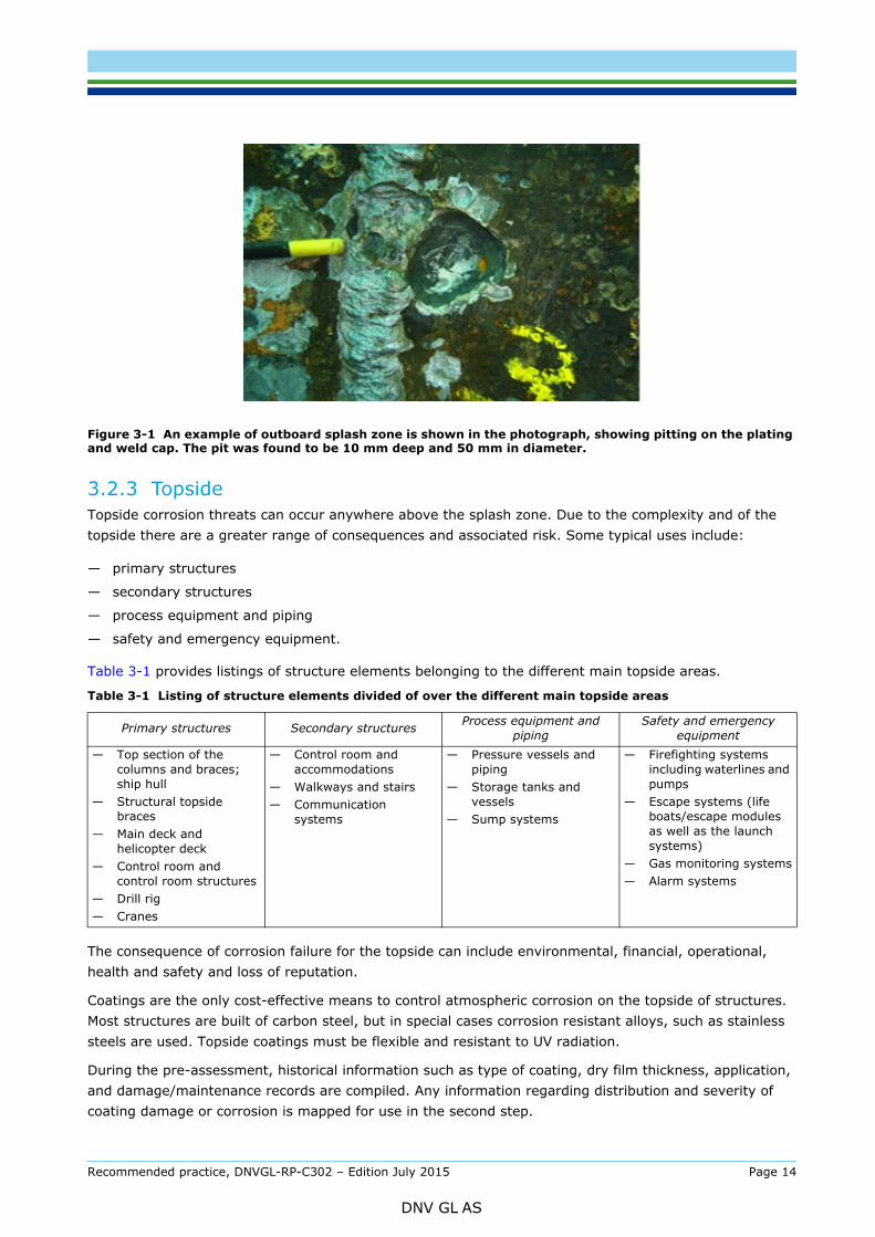
Figure 3-1 An example of outboard splash zone is shown in the photograph, showing pitting on the plating and weld cap. The pit was found to be 10 mm deep and 50 mm in diameter.
3.2.3 TopsideTopside corrosion threats can occur anywhere above the splash zone. Due to the complexity and of the topside there are a greater range of consequences and associated risk. Some typical uses include:
— primary structures
— secondary structures
— process equipment and piping
— safety and emergency equipment.
Table 3-1 provides listings of structure elements belonging to the different main topside areas.
The consequence of corrosion failure for the topside can include environmental, financial, operational, health and safety and loss of reputation.
Coatings are the only cost-effective means to control atmospheric corrosion on the topside of structures. Most structures are built of carbon steel, but in special cases corrosion resistant alloys, such as stainless steels are used. Topside coatings must be flexible and resistant to UV radiation.
During the pre-assessment, historical information such as type of coating, dry film thickness, application, and damage/maintenance records are compiled. Any information regarding distribution and severity of coating damage or corrosion is mapped for use in the second step.
Table 3-1 Listing of structure elements divided of over the different main topside areas
Primary structures Secondary structures Process equipment and piping
Safety and emergency equipment
— Top section of the columns and braces; ship hull
— Structural topside braces
— Main deck and helicopter deck
— Control room and control room structures
— Drill rig— Cranes
— Control room and accommodations
— Walkways and stairs— Communication
systems
— Pressure vessels and piping
— Storage tanks and vessels
— Sump systems
— Firefighting systems including waterlines and pumps
— Escape systems (life boats/escape modules as well as the launch systems)
— Gas monitoring systems— Alarm systems
Recommended practice, DNVGL-RP-C302 – Edition July 2015 Page 14
DNV GL AS

corrosion:
— Corrosion often starts in areas of coating damage, and areas where the coating can be of poor quality e.g. weld seams, edges, and notches.
— Stress and strain caused by overloads, reductions in steel dimensions as a result of corrosion, dents, wear, repair work, etc., may produce damage to coatings.
— Stresses and vibration may result in increased corrosion and cracks.
— Welds or heat-affected zones (HAZ), where coating may be of poor quality as a result of poor pretreatment or where welding work has been done after the coating has been applied and not properly repaired.
— Complicated shaped structures with poor access, which make it difficult to inspect or to provide efficient protection, are particularly liable to suffer from undetected corrosion.
— Horizontal surfaces or areas that are not satisfactorily drained or where deposits of foreign matter are present, may suffer significant corrosion.
— Steel surfaces hidden under thermal isolation or isolating materials used for fire protection.
— General or uniform corrosion over a long period of time can have serious consequences for the structural integrity of topside structures.
3.2.4 Tanks and internal structuresCorrosion threats from internal surfaces such as ballast tanks, chain lockers, oil tanks, pump rooms, and void tanks are subject to all three exposure zones, i.e. submersed, splash and atmospheric. Because of limited accessibility and often more corrosive environments, tanks and internal structure pose a serious corrosion threat. The threat level depends on the location of the tanks, i.e. inside or outside, their contents and the exposure zone.
Ballast tanks generally pose the highest threat, because they contain (often contaminated) seawater, which is at varying levels inside the tank. These tanks require a combination of coating and cathodic protection to control corrosion in locations where the tanks are submerged. Sacrificial anode CP is exclusively used in this case, because of the changing water levels and because of potential hydrogen evolution impressed current CP in confined spaces. Note that cathodic protection maybe ineffective in water containing hydrocarbons.
When identifying threats and consequences, specific attention must be paid to the areas subject to:
— Wet and dry conditions (under-deck and shear strakes), since those area are most prone to coating breakdown and corrosion, particularly when they are wet and exposed to the atmosphere.
— Horizontal surfaces (e.g. tank top), where the buildup of sediment, sludge and other material can exacerbate the corrosion process.
Additional conditions to be considered include the following:
— Long spans of flexible stiffeners may allow sufficiently high deflections that disbond coatings, exposing the steel accelerating the corrosion.
Example (continued)In the case of external corrosion of the upper column segments or braces, general corrosion is the greatest threat. If wide spread general corrosion is allowed to occur over a long period of time, this could result in extensive wall loss, which could reduce the global strength of the column as well as its buckling capacity. The entire rig could then be at risk of collapsing.External corrosion of other topside structures, such as process equipment and piping results in different threats and consequences. For example, localized corrosion or cracking of pressure vessels containing sour gas could result in a toxic release affecting the safety of the rig crew.
Recommended practice, DNVGL-RP-C302 – Edition July 2015 Page 15
DNV GL AS
Of particular concern is the presence of sand particles in the ballast water.
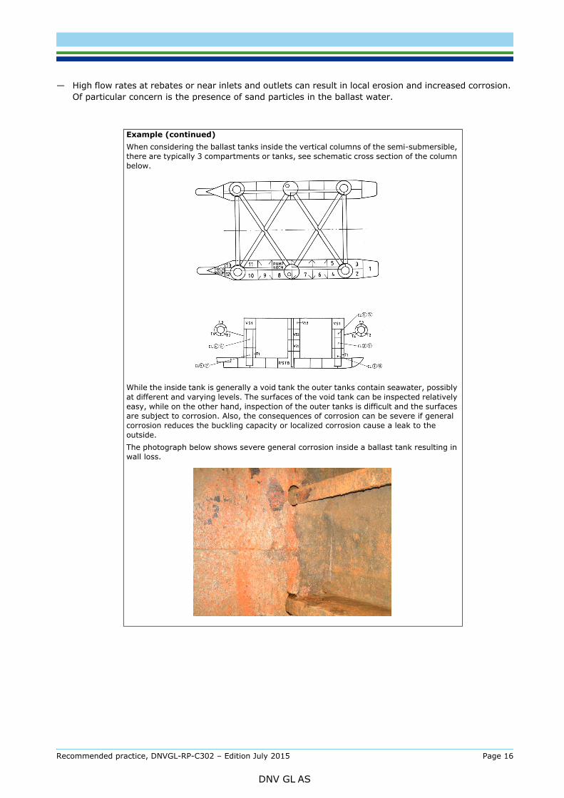
Example (continued)When considering the ballast tanks inside the vertical columns of the semi-submersible, there are typically 3 compartments or tanks, see schematic cross section of the column below.
While the inside tank is generally a void tank the outer tanks contain seawater, possibly at different and varying levels. The surfaces of the void tank can be inspected relatively easy, while on the other hand, inspection of the outer tanks is difficult and the surfaces are subject to corrosion. Also, the consequences of corrosion can be severe if general corrosion reduces the buckling capacity or localized corrosion cause a leak to the outside.The photograph below shows severe general corrosion inside a ballast tank resulting in wall loss.
Recommended practice, DNVGL-RP-C302 – Edition July 2015 Page 16
DNV GL AS

4.1 Screening generalAfter the relevant information and historical data gathered in step 1 (desktop exercise), the screening completes the collection of information and establishes the current status or condition of the unit and extent of known issues.
The screening may consist of one or more of the following:
— general visual inspection of the whole unit and available tanks, noting coating breakdown location and corrosion scale and anode condition
— quantitative readings from monitoring that is already in-place and functioning (e.g. electrochemical potential reading of the impressed current CP system)
— available footage from ROV.
It is emphasized that all elements are on an opportunity basis and are not mandatory. The objective of this step is to complete the status overview of the unit, confirming conclusions on corrosion risk areas achieved Step 1, and by doing so improving the confidence in the risk ranking results as will be discussed further in [4.3].
4.2 Screening for different zones
4.2.1 SubmergedA possible screening for the submerged structures is based on the electrochemical potential and current distribution grid which may have been developed in step 1. For this, electrochemical potential measurements taken at prefixed locations and at different depths around the submerged structure are used to create actual potential and current (density) maps. Superimposing these onto earlier collected- or generated potential and current (density) maps will identify actual hot spots, where possible coating damage exists and corrosion is likely to occur.
4.2.2 Splash zoneThe screening for the splash zone includes visual inspection and photographic recording with a specific focus on those locations that were identified as having specific threats or consequences in step 1. Otherwise, the visual/photographic inspection of primary and secondary structures exposed to the splash zone is global in
Example (continued)Using a finite element comparison model, specific locations of coating breakdown and potential corrosion are identified, and hence potential external threats to the external submerged structure. Actual potentials are measured and an FEA map of the potential is calculated. Superimposition of the “design” map over the actual map indicates the locations of coating breakdown and specific threats.
Recommended practice, DNVGL-RP-C302 – Edition July 2015 Page 17
DNV GL AS

should be recorded such that in later steps the exact location of specific observations can be found. The location is identified by detailed description, or by painting on the structures.
The photographically recorded coating damages and corrosion should be compared with historic inspection and maintenance data. The results of this analysis will confirm the threats and consequences, and are used to calculate the risk levels for the splash zone.
4.2.3 TopsideThe screening of topside structures consists of a general visual inspection and photographic recording of coating damage and corrosion to confirm conclusions reached during step 1. The scope of the general inspection depends on the historic inspection and maintenance records that were collected. The areas to be addressed are listed in [3.2.3].
4.2.4 Tanks and other internal structuresThe screening for tanks and other internal structures may consist of visual inspection of the protective coatings and corrosion and inspections of the sacrificial anodes. As a supplementary alternative the electrochemical potential and current distribution grid as discussed for the submerged zone may be used as is further described in the continuing example below.
The condition of the sacrificial anodes indicates areas which require close inspection. Specific features to note on the sacrificial anodes are metal loss and the degree of uniformity in metal loss. Note that sacrificial anodes must not be painted.
A general guideline for replacing sacrificial anodes is that the anodes must be replaced when an estimated 60% metal loss is achieved. Replacement is also required if the anode is unevenly consumed as is shown in the figure below. Knowledge of the initial dimensions of the sacrificial anode is required in order to carry out such estimates. To assess anode consumption it may be necessary to remove corrosion products and marine growth.
Example (continued)The submersed parts of ballast tanks are protected by a combination of coatings and sacrificial anode cathodic protection. The electrochemical potential distribution can be modeled with FEA and similar to the external potential modeling, hotspot or areas that can pose specific threat can be identified by superimposing a map with actually measured values over the design map, indicating location of coating breakdown. A shown in the figure, the design potential map can also indicate areas under protection due to shielding.
Recommended practice, DNVGL-RP-C302 – Edition July 2015 Page 18
DNV GL AS

Figure 4-1 Corrosion at sacrificial anode; from left to right on attachment only, partially and completely consumed
4.3 Risk rankingThe objective of the risk ranking following the data collection is to establish priorities for the detailed examination in step 3. For this, the threats and consequences as were defined in step 1, are evaluated as risk, which is the product of the probability of failure and the consequence of failure.
The risk assessment matrix as was already shown in Figure 2-3, is a grid which identifies levels of threat likelihood on the one axis, and levels of consequence severity on the other. The levels of likelihood and consequence severity correspond to positions on the matrix for each component, equipment, section or segment. The probability (likelihood) levels on the matrix are typically assigned letter values “A-E” with “A” being the lowest level and “E” being the highest level. Consequence severity levels on the Risk Assessment Matrix are typically assigned number values from 1-7 with 7 being the highest severity consequence. It is up to the individual company to decide the extent of the risk matrix, i.e. 5x5, 6x6, 7x7etc.
Subsequently, the resulting risk levels on the matrix are associated with varying levels of risk acceptance as defined by the rig owner. These are indicated by high, medium and low risk typically with different colors, e.g. red, yellow and green:
High: High risk levels are seen as unacceptable and require immediate attention. Risks of thismagnitude require the authority of the rig owner or asset stakeholders.
Medium: Medium risk often represent the as low as reasonably possible (ALARP) areas, and need to beevaluated to determine if additional control measures should be incorporated, where feasibleand financially practical. Required authority at this level requires middle- to upper-management level.
Low: Low risks in the green region represent tolerable risks which do not require further action.Required authority at this level can be at the low- to middle-managerial level.
The continuation of the step 1 example as given below, illustrates the outcome of this step further.
Example (continued)The threats and consequences of corrosion in each of the exposure zones differ and are listed in the diagram below and given the color codes of acceptable, ALARP and unacceptable. The risk numbers correspond to the likelihood and consequence levels defined in the RAM. For example, external corrosion of submersed parts may have a relatively low risk for health and safety, but in case of collapse, environmental, financial and reputation consequences are high. Note that these designations may differ for different Corporate Risk Assessment Matrices, which are based on the risk tolerance of the Company. The figure shown below is not a risk assessment matrix. It assigns risk levels to be entered into the Corporate Risk Assessment Matrix for further analysis.
Recommended practice, DNVGL-RP-C302 – Edition July 2015 Page 19
DNV GL AS

5.1 GeneralOnce the high-risk locations are identified in step 2, the 3rd step continues with detailed examination of these areas. The objective of this step is to obtain more in-depth information about coating damage and corrosion at the high-risk locations, so that the risk levels can be further refined and appropriate follow-up can be established.
An important difference with the step 2 Screening is, from risk management point of view, the mandatory nature of the examinations in this step; an inspection is required as an (initial) follow up action of the identified unacceptable risk of the location.
This may also entail specific tank access and quantitative monitoring in order to establish the coating condition and extent of the corrosion. For clarity it is emphasized that the mandatory status and the subsequent inspection requirements are based on a company’s risk acceptance and not related to statutory or class regulations.
The type of information that would be of interest, include excessive wall thickness loss (both general uniform and localized corrosion), the onset and growth of cracking, the magnitude of any stresses and loads, the performance and integrity of protective coatings, the level and effectiveness of corrosion mitigation schemes (e.g., cathodic protection and corrosion inhibitors), and environmental factors such as temperature, relative humidity, pH, and chloride concentration.
How the information is obtained varies for the different zones and is discussed in [5.2].
5.2 Coating condition and corrosion assessment
5.2.1 SubmergedOnce the inspection locations have been identified by the Risk Ranking (step 2), a close visual inspection (CVI) of the underwater locations is performed by diver or camera mounted ROV. Generally it is necessary to remove any marine growth in the region to be inspected. If indicated by the photography or video, ultrasonic thickness measurements (UTM) are also taken.
The underwater inspection should include a survey of the CP system, including measurement of the electrochemical potential at critical locations and visual/photographic assessment of the physical condition of the anodes (sacrificial and impressed current) and anode wires of the ICCP systems.
5.2.2 Splash zoneAfter identifying the high risk locations in the splash zone, these locations are inspected in more detail using boats, divers, ROVs or rope access. In order to be able to carry out a detailed visual inspection, marine growth and corrosion product must be removed.
Standard gauging and/or NDT (i.e. ultrasonic testing) are typically used for determining wall loss. Magnetic Particle Inspection (MPI) and/or Eddy Current Inspection (ECI) are commonly used to detect cracks or crack-like features in special areas.
5.2.3 Top sideAn initial detailed visual examination may be sufficient to assess the threat, but also could identify the need for NDT such as ultrasonic thickness testing. It should be noted that the most severe topside corrosion often occurs in crevices (i.e. narrow cracks), where localized crevice corrosion can result in rapid wall loss, under insulation and at the underside of a structure where salt, condensation and other deposits may build up and are not washed away by rain. Often, those areas of potentially severe corrosion are not easily detected.
5.2.4 Tanks and internal structuresTanks and other internal structures require special attention, because of the presence of aggressive environments and because of poor accessibility; the steel walls are difficult to protect, because of the changing water levels. While the submersed areas are protected by a combination of coating and cathodic
Recommended practice, DNVGL-RP-C302 – Edition July 2015 Page 20
DNV GL AS

to alternate immersion and drying.
Thus, tanks and internal structures are visually examined in detail, where accessible with particular focus on the wet-dry zones. These areas are inspected with close visual inspection and where required with appropriate NDT tools.
The submerged areas are initially inspected by assessing the effectiveness of the sacrificial anode protection system, which can be accomplished by measuring the electrochemical potentials at the location identified as “hot spots” in [4.2.4]. If these measurements indicate insufficient cathodic protection, the anodes must be checked and where needed replaced. If after replacing the anodes, the level of protection is still insufficient, diver may be needed for further inspection.
Recommended practice, DNVGL-RP-C302 – Edition July 2015 Page 21
DNV GL AS

6.1 GeneralThe detailed examination in step 3, not only resulted in more detailed information on coating damage and corrosion, they also revealed those areas which require follow up step in the form of remediation.
Depending on the degree of corrosion damage, the rig owner can decide on replacement, repair and/or improved corrosion management (incl. mitigation). If replacement or repair is selected, the resulting structure must be protected from future corrosion by proper corrosion management. The objective of remediation is to lower the probability of failure, that is to lower the risk to the structure due to corrosion.
From a corporate risk matrix perspective, the above implies that risks exceeding the company threshold (red status) are addressed with the aim of reducing the risk to a lower (yellow) category. The continuing example below shows this.
The evaluation and selection of protective measures against corrosion depend on the operational philosophy of the rig owner, the market, type and age of ship, trade, costs relative to the rig's lifetime, etc. There may also be new regulations affecting allowable methods. The following paragraphs discuss the most important protective measures:
— coatings— cathodic protection— corrosion monitoring— corrosion inhibition.
In the case of more extensive corrosion, damage may be repaired using the bonded patch method outlined in [6.6].
6.2 CoatingsEpoxies and epoxy polyesters are the most common types of coatings for external and internal surfaces. The quality, and thus the useful life, of coatings depend primarily on the cleanness and pretreatment of steel surfaces, and on prevailing conditions while the coatings are being applied. Other important requirements concern coating thickness and number of coats.
Coatings are designed to perform under specific conditions, consequently no single coating type will be the best under all circumstances. For example, there are different requirements for immersion, splash and
Example (continued)Following the Detailed Inspection step, remediation will be implemented depending on the severity of the defect. In the example of the semi-submersible column, immediate attention would have to be given to the high risk locations (red). Once the external splash zone is repaired and recoated, the probability or frequency of corrosion in those locations can be reduced from 4 to 3. Because of the aggressiveness of the splash zone environment, the number cannot go below 3. The repair has moved two of the risks into ALARP. However, since the consequences to reputation and finances still remain high (E) the risk here remains high as well. Similarly, remediation in the ballast tank is shown to have lowered one risk category. Like in the previous figure, this matrix below is not a risk assessment matrix, but an assignment of risk, reduced after remediation, completed with the acceptance levels from the Corporate Risk Assessment matrix.
Recommended practice, DNVGL-RP-C302 – Edition July 2015 Page 22
DNV GL AS

system and have antifouling or fouling- release properties and withstand some erosion and atmospheric coatings must be UV resistant and esthetic (for some applications).
The requirements are also different for the type of asset, where it will always be up to the owner to optimize as necessary. It is important to be aware of this in connection with the testing and classification of coatings. Table 6-1 shows typical coating requirements for the three external corrosion zones. The Appendix provides a detailed description of the various coating applications for marine environments.
6.3 Cathodic protection Cathodic protection of steel structures is conducted by making the steel structure the cathode in an electrochemical cell. Cathodic protection may be achieved with:
— Sacrificial anodes (made of specially designed aluminium or zinc alloys).
— Impressed current systems.
Adequate cathodic protection (CP) is obtained when the electrochemical potential of the steel surface measured with a reference electrode has been moved (polarized) to a value more negative than the defined protection potential, e.g. between -800 mV and -1000 mV versus a Ag/AgCl/seawater reference electrode. Below the protection potential, the corrosion rate of the steel is decreased to negligible values, while over-protection will generate hydrogen on the cathodic surface, which results in the threat of cracking of high-stressed carbon steel members. The fundamental requirements to cathodic protection of hull and tanks are given in the Rules for MOU. More details are described in the DNV Guidelines No. 20 Corrosion Protection of Ships, and recommended practice DNV-RP-B401 Cathodic Protection Design.
Sacrificial anodes are used for CP of combined tanks and segregated ballast tanks. Because hydrogen gas can be generated inside the tanks, the use of impressed current systems in tanks is not allowed. Cathodic protection only works when both the sacrificial anodes and the structures they are to protect are immersed in water. Time in ballast is therefore an important factor to be taken into account when considering the protective effect of sacrificial anodes. A combination of cathodic protection and other types of protection (coatings, corrosion inhibitors, dry inert gas, etc.) can provide good protection over a long period of time. A combination of corrosion protection methods is important because cathodic protection does not extend to the upper regions of a tank.
If, based on the direct examination of an – induced current cathodic protection (ICCP) system, the cathodic protection system is deemed insufficient, the current may be adjusted, according to procedures described in DNV-RP–B401 Cathodic Protection Design.
Table 6-1 Coating application for 3 external corrosion zones
Zone ISO class Corrosion rates 1) Coating types 2) Coating system Applicable standards Comments
Atmospheric C5-M 80 to 200 μm (3 to 8 mils)
Zn-rich primer, epoxies and UV durable topcoat
Minimum 320 μm (13 mils) in minimum of 3 coats
Splash 200 to 500 μm (8 to 20 mils)
Epoxy polyester Minimum 600 μm (24 mils) in minimum of 3 coats
Immersion (Im2) 100 to 200 μm (4 to 8 mils)
Epoxy Minimum 450 μm (18 mils) in minimum of 2 coats
NACF TM0204 – Exterior Protective Coatings for Seawater Immersion ServicesNACF TM0104 – Offshore Platform Ballast Water Coating Evaluation
Coating must be compatible with cathodic protection
1) corrosion rates are average rates carbon steel in the three exposure zones (Corrosion of Metal in Marine Environments MCIC-86-50 (1986))
2) based on DNVGL-RP-B101 – Corrosion Protection of Floating Production and Storage Units and applicable NACE Standards
Recommended practice, DNVGL-RP-C302 – Edition July 2015 Page 23
DNV GL AS

deemed insufficient, the sacrificial anodes may be replaced. Indication of insufficient sacrificial anode protection can be, completely consumed anodes, unevenly consumed anodes, or anodes that don’t appear to have been consumed. The latter case may indicated that either the anode is not connected to the steel or that something is shielding the anode preventing it to work as intended.
6.4 Corrosion monitoringIf coating damage or corrosion is minor, corrosion monitoring may be an option. Corrosion monitoring is done using corrosion coupons or corrosion probes. While inspection of a surface establishes the amount of corrosion damage done on a structure directly, corrosion monitoring can assess the corrosivity of the environment, and may therefore more predictive.
6.4.1 Corrosion couponsThe simplest form of corrosion monitoring is the use of uncoated corrosion coupons. These coupons can be in the form of unstressed or stressed material specimens that are exposed to the actual operating environment of interest. Over time, the coupons are removed from exposure and examined.
The examination that is done can vary but typically involves measuring any weight change to look for loss due to corrosion or gain resulting from scale formation. Visual observation of the physical appearance of the coupons is also conducted to note for overall thinning, the presence of localized corrosion and/or cracking and any corrosion products that are present.
Coupons offer the advantage of providing some information on corrosion modes and rates in a relatively simple and easy to interpret form. They, however, only provide a time-averaged picture over the course of the exposure. That is, it is usually not possible to determine when corrosion initiated and terminated when examining a coupon and thus it is assumed to have corroded at a constant rate throughout the exposure period. The other limitation is that the installation, retrieval, assessment, and installation of new coupons requires human interaction and cannot readily be automated.
6.4.2 Corrosion probesThe above two disadvantages of corrosion coupons do not apply for the corrosion probes. Although not common in the off-shore and maritime industry, corrosion probes have been used in many from pipelines to power utilities and refineries. Their capability to deliver a time-based assessment of the corrosivity of the environment without human interaction, is most important for changing environmental conditions, or in difficult-to-access areas, such as in internal cavities or tanks. The disadvantage of corrosion probes is that when they are installed in a remote locations they require long electrical leads, which can be severed.
Electrical resistance (ER) corrosion probes their functioning is based on measuring the resistance of a sensing element. As the sensing element corrodes, its cross sectional area decreases and its resistance increases according to:
Where R is the resistance, ρ is the resistivity of the metal, l is the length of the element, and A is the cross sectional area.
6.5 Corrosion inhibitionCorrosion inhibitors can be used in closed systems, such as closed-loop on board cooling, if care is taken that the chemicals are not vented to the sea.
The addition of chemicals to ballast water or cargo can reduce corrosion, but an evenly distributed concentration over time on all parts of the structure is necessary. In practice this is difficult to achieve on board of rigs at sea. Environmental considerations mean that it is not permitted to pump contaminated water over board (chromates, phosphates, etc.) Corrosion inhibitors have been used on board ships and rigs that are laid up, and for this purpose they can be quite suitable.
AlR ρ=
Recommended practice, DNVGL-RP-C302 – Edition July 2015 Page 24
DNV GL AS

The original structure was designed for certain loads. A corrosion damage reduces its capability and the structure needs repair. Instead of welding, a patch will be bonded onto the structure to restore integrity. DNVGL-RP-C301 outlines the assessment and decision making process on whether to proceed with a bonded patch repair. Furthermore it provides a design and qualification process to design and fabricate bonded patches. The repair procedures applied to patches of composite material, steel or other structural materials.
Recommended practice, DNVGL-RP-C302 – Edition July 2015 Page 25
DNV GL AS
Offshore installations are designed to ensure a safe and economical operation during their intended life. Deterioration processes, such as corrosion and fatigue crack growth commence from day one. Thus, in order to ensure that the condition of the installations remains in compliance with the safety requirements throughout their operational life a certain amount of inspections, condition monitoring and maintenance is required throughout the service life of the installations. The control and steering of these inspections, monitoring and maintenance is part of life cycle management, with the objective to:
— Create confidence in the condition of the offshore rig and the process in place for corrosion management.
— Enhance the performance of the rig by establishing a cost-effective maintenance and inspection plan.— Increase the reliability of the rig through consistent inspection planning and reporting.
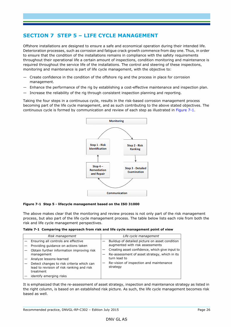
Taking the four steps in a continuous cycle, results in the risk-based corrosion management process becoming part of the life cycle management, and as such contributing to the above stated objectives. The continuous cycle is formed by communication and review of each step as illustrated in Figure 7-1.
Figure 7-1 Step 5 - lifecycle management based on the ISO 31000
The above makes clear that the monitoring and review process is not only part of the risk management process, but also part of the life cycle management process. The table below lists each role from both the risk and life cycle management perspectives.
It is emphasized that the re-assessment of asset strategy, inspection and maintenance strategy as listed in the right column, is based on an established risk picture. As such, the life cycle management becomes risk based as well.
Table 7-1 Comparing the approach from risk and life cycle management point of view
Risk management Life cycle management— Ensuring all controls are effective— Providing guidance on actions taken— Obtain further information improving risk
management— Analyze lessons-learned— Detect changes to risk criteria which can
lead to revision of risk ranking and risk treatment
— identify emerging risks
— Buildup of detailed picture on asset condition augmented with risk assessments
— Creating asset confidence, which give input to— Re-assessment of asset strategy, which in its
turn lead to — Re-vision of inspection and maintenance
strategy
Recommended practice, DNVGL-RP-C302 – Edition July 2015 Page 26
DNV GL AS

risk areas. It may well be that inspection and maintenance intervals are acceptable on green, low risk areas and as such cost over the life cycle is lowered. The continuing example below makes clear these effects.
Example (continued)The completion of the four stages on our example rig, have revealed high risks on the external splash zones and ballast tank for one of the columns of the rig. Since the rig is chartered under profitable terms, the management decides after being informed of the situation to continue the operation at the same time increasing the number of inspections to the affected and identified areas to a monthly interval. Notwithstanding, the company has a reputation of modern units with a high availability of their units. The corrosion gives a risk on this reputation. The company has now two alternatives. The first is to lower market expectations regarding high availability and adjust their charter levels accordingly. The second is to bring forward in time replacement investments for the asset under discussion. It is decided to enforce the asset strategy and seek for a new build replacement.
Recommended practice, DNVGL-RP-C302 – Edition July 2015 Page 27
DNV GL AS

A.1 IntroductionThe factors affecting corrosion of rigs in marine environments are:
1) the selected design and related structures of the rig
2) the materials used for construction of the rig
3) the exposure environments, and
4) the corrosion protection methods.
In the following paragraphs the factors are discussed in detail.
A.2 Design and related structures Floating offshore structures are categorized into 3 areas, Special, Primary and Main Class.
— Special areas are those sections of the Structure which are in way of critical load transfer point, stress concentrations, often special steel selection etc. Ref. DNVGL-OS-C101 Ch.2 Sec.3. See also, DNVGL-OS-C103 Ch.2, Sec.1(2) and DNVGL-OS-C201 Ch.2, Sec.10(2).
— Primary areas are elements which are essential to the overall structural integrity of the unit. See also DNVGL-OS-C103 Ch.2, Sec1(2) and DNVGL-OS-C201 Ch.2, Sec.10(2).
— Main Class Elements are all other areas which are not Special or Primary.
For the purpose of corrosion management the structural area categorization is considered in conjunction with the appropriate exposure zone:
- subsea- splash- topside- internal (tanks and other internal structures).
A.3 Materials of constructionHull structures are normally built of carbon or carbon-manganese steel. Column stabilized offshore units are more likely to use higher strength steel than traditional ship shaped units, resulting in reduced plate thickness and lower weight. DNVGL-OS-B101 provides the full chemical composition of these steels. One of the more common forms of corrosion is galvanic corrosion, caused by contact between dissimilar metals. Thus, measures should be taken to avoid contact between dissimilar metals. If contact cannot be avoided, the anode/cathode ratio must be reduced by, for example, applying a coating over the cathodic part of the couple.
Stainless steel is being used in a number of areas, such as chemical tanks and piping. Problems may occur with stainless steel as a result of insufficient knowledge of the material and consequently inappropriate use. The austenitic type stainless steel in most common use; AISI 316 (max. 0.03% C, 18.5% Cr, 14.5% Ni, 3.0% Mo) is not resistant to pitting and stress corrosion cracking in seawater. Stagnant, oxygen-poor seawater is particularly damaging to stainless steel, as rapid localized corrosion in the form of pitting or crevice corrosion may occur, especially if the seawater is warm. If stainless steel comes into electrical contact with common carbon steel in seawater or the marine atmosphere, the result may be galvanic corrosion of the carbon steel or welds. Stainless steels with molybdenum content above 6% (e.g. 0.02% C, 20% Cr, 18% Ni, 6.1% Mo, 0.2% N, and 0.7% Cu) are more resistant to pitting and crevice corrosion than 316L.
Thermo-mechanical controlled processing (TMCP) has become more common and its qualities include high strength and toughness, and it also has a lower carbon equivalent, giving it better weldability than traditional steels such as normalized steel. TMCP steel is supplied in “normal strength”, “high strength” and “extra high strength” qualities up to yield stress of 500 to 550 MPa.
Recommended practice, DNVGL-RP-C302 – Edition July 2015 Page 28
DNV GL AS

A.4.1 IntroductionSeawater is the most abundant naturally occurring electrolyte. Most of the common metals and alloys of construction are attacked by seawater or moisture laden sea air. The performance of materials may vary widely, according to the specific exposure zone involved.
The following subsections describe the corrosion environments to which rigs are exposed and the corrosion mechanisms that occur in the different exposure zones (atmospheric, splash, submerged and internal tanks).
A.4.2 Atmospheric zone Deposition of sea mist and sea salt occurs on materials exposed in marine atmospheres. The salts are deleterious to most common steels and alloys, promoting localized attack; their hygroscopic nature and sea mist provide an electrolyte, which is necessary for the attack to occur while the anions (i.e. chlorides) promote film breakdown on passive metal surfaces. The mere presence of the deposits may also promote the formation of differential aeration cells
The salt deposition process is a function of many variables including wind and wave conditions, height above sea, distance from shore, surface orientation, degree of sheltering, and the amount and distribution of rain during a given time period. In general, those conditions which promote salt buildup and prevent rainfall from removing the salt, promote the most severe corrosion. Thus, the bottom sides of structures or those structures which are sheltered from rain generally suffer more corrosion.
Fungi and mold also may deposit on metal surfaces in marine atmospheres. These organisms may promote corrosion by formation of differential aeration cells and by holding moisture on the metal surface.
A.4.3 Splash zoneMaterials in the splash zone are almost continuously wetted with well aerated seawater. For materials, such as carbon and low-alloy steels, which do not form thin, tenacious passive films, the splash zone is the most aggressive of the marine exposure zones.
Metals which form tightly adhering passive films such as stainless steels, generally perform well in the splash zone because the well aerated conditions promote passivity.
A.4.4 Immersion zone The major factors that affect corrosivity of the immersion zone are:
— OxygenOxygen affects the corrosion rate of metallic materials by providing a cathodic reaction (O2 + 2H2O + 4e- → 4OH-) having a relatively noble equilibrium potential and rapid kinetics. For corrosionallowance materials such as steels, the presence of oxygen greatly increases rates of corrosion since thecorrosion kinetics are limited, in many cases, by the rate of the cathodic or reduction reaction. On theother hand, the presence of oxygen generally reduces rates of attack of corrosion resistant materials suchas stainless steels by promoting passivation. However, where the oxygen supply to a passive metalsurface is limited locally, such as in crevices, the presence of oxygen on boldly exposed surfaces maypromote localized attack.
For the corrosion allowance materials, the rate of oxygen reduction reaction is generally limited by therate of oxygen transport of oxygen to the metal surface. Thus, factors which influence the rate oftransport such as oxygen concentration of the seawater and velocity of the seawater also affect thecorrosion rate
— Biological activityWhen a metal or other surface is first immersed in seawater, a biological slime tends to develop withinmatters of hours. Subsequent to the formation of biological slime film, embryonic sessile organismsbecome firmly attached. Once attached, they rapidly transform to a mature form.
Recommended practice, DNVGL-RP-C302 – Edition July 2015 Page 29
DNV GL AS

in marine environments. For corrosion allowance materials, fouling may actually reduce rates of attackby limiting the supply of oxygen to the metal surface. However, the decay and by-products of marineorganisms can be aggressive and promote localized attack of both corrosion resistant and corrosionallowance materials. Moreover, the simple presence of marine organisms can aid in the development ofdifferential aeration cells.
— Temperature
The effect of temperature on the corrosion of metals is complicated by the interdependence of otherrelevant parameters and temperature. The kinetics of activation-controlled oxidation reactions anddiffusion-controlled reduction reactions increase with increasing temperature. On the other hand, thepassivation phenomenon is a complex function of temperature since the stability of the films and therate of formation are affected.
In addition, oxygen solubility in seawater decreases with increasing temperature and calcareousdeposits exhibit retrograde solubility, increasing the likelihood of precipitation of protective scales atelevated temperatures.
Biological activity increases with increasing temperature over the temperature range near ambient,which can be either beneficial or deleterious.
— Velocity
The corrosion rate of corrosion allowance materials such as steels and copper-base materials normallyincreases with increasing seawater velocity, since the rates of attack of these metals are frequentlylimited by the availability of oxygen at the metal surface.
In addition, high velocities tend to erode barrier films which form on alloys such as copper-base alloys.Passive metals, such as stainless steels, are highly resistant to flowing seawater. Indeed, piping ofstainless steels is less likely in flowing seawater than under stagnant conditions.
— Salinity
The major oceans of the world are completely connected in the southern hemisphere, and it thereforeno surprise that the relative proportion of salts does not vary appreciably in these interconnectedoceans; variations in salinity in open ocean surface waters typically range from 3.2 to 3.5 percent. Inthis range, the corrosion rate of common metals does not change appreciably.
Large variations in salinity are found in more isolated areas. These salinity variations are usuallyaccompanied by other chemical changes in the seawater and thus the overall effect on corrosionbehavior is difficult to predict.
— pH
The pH of seawater may vary slightly depending on photosynthetic activity. Plant matter activityconsumes carbon dioxide and affects the pH during daylight hours. Carbon dioxide content in seawateris influenced close to the surface by exchange with carbon dioxide in the atmosphere. A daily shift in pHfrom, say, from 8.0 to 8.2 has little direct effect on the corrosion behavior; however, it can be a factorin calcareous scale deposition which, in turn, influences corrosivity.
As pressure is increased, the pH is reduced according to thermodynamic considerations. Thus, at greatdepths, there is some evidence of fewer tendencies for protective carbonate type scales to form.
A.4.5 Internal tanks The degree of corrosion in internal tanks depends on various parameters, as listed below:
— Ballast cycle for ballast tanks
— Corrosion increases with increasing periods in unprotected, empty, humid conditions.
— Cathodic protection has no effect on empty tanks.
Recommended practice, DNVGL-RP-C302 – Edition July 2015 Page 30
DNV GL AS
— Damp surfaces in empty or incompletely filled tanks will corrode, particularly at high temperatures and in the presence of salt.
— Rust and sediments will retain humidity and salts and result in continuous corrosion.
— Temperature
— Elevated cargo, bunkers oil or engine room temperatures increase the risk of corrosion in adjacent ballast tanks.
— Sun-warmed decks increase corrosion in the tops of tanks.
— Oxygen concentration
— Under hatches, valves and other tank apertures, a combination of humidity and high oxygen availability (outside air) can result in increased corrosion.
— Variations in availability of oxygen can occur, for example, at different water depths in ballast tanks and under sediments. This can result in increased corrosion. (Local galvanic potential differences are created).
— Tank content
— Cargoes containing water and oxygen with low pH (acid) will lead to increased corrosion.— Water settling out from crude oil may contain up to seven times as much dissolved oxygen as
seawater.— Cargoes and crude oil that contain sulfur can form sulfuric acid which increases general corrosion
and pitting on horizontal surfaces and particularly in the tank bottoms. — Hydrogen sulfide (H2S) in crude oil can raise H2S levels above the cargo to dangerous levels.
Hydrogen sulfide is extremely toxic and flammable. — Oil or other cargoes that leave a waxy or oily film on surfaces can reduce corrosion but may also
passivate sacrificial anodes for periods of time. — In cargo holds, combinations of sulfur-containing coal, ore, metals, etc. and seawater may result in
severe corrosion. — Microbial influenced corrosion (MIC) occurs in oil tanks, ballast tanks, etc. as cluster of pits.
Conditions that encourage bacterial corrosion are stagnant water, adequate nutrition for bacteria sulphate and suitable temperature (20 to 40ºC).
Local galvanic corrosion of welds or heat-affected zones (HAZ) may be severe. Figure A-1 shows a diagram with areas in a ballast tank that are susceptible to corrosion.
Recommended practice, DNVGL-RP-C302 – Edition July 2015 Page 31
DNV GL AS

Figure A-1 Areas in ballast tanks susceptible to corrosion
A.5 Corrosion protection methods
A.5.1 OverviewThe main means of corrosion protection of carbon steels in marine environments is the proper use of coatings. In submersed conditions, corrosion protection can be enhanced by cathodic protection. The coating requirements may be different for the different exposure conditions, where subsea coatings have to be compatible CP and have antifouling properties, while topside or atmospheric coating have to be UV resistant.
A.5.2 CoatingsA.5.2.1 IntroductionWhile epoxies and epoxy polyesters are the most common types of coating for marine structures, other types of coating are used as well. The following gives a description of the various types of coating used in marine environments.
A.5.2.2 EpoxyEpoxies consist of two-component chemically curing systems with the following general properties:
— good corrosion prevention properties as a result of their barrier effects
Recommended practice, DNVGL-RP-C302 – Edition July 2015 Page 32
DNV GL AS

— withstand mechanical wear, but become chalky with outdoor exposure — withstand temperatures up to about 100°C— usually require 10°C to cure, but winter grades cure at lower temperatures — for optimal result, need blast cleaning to at least Sa 2½ — application on top of other types of paint, such as vinyl, chlorinated rubber and alkyd entails the risk of
dissolution (lifting) of previous coats — the minimum and maximum curing times between successive coats must be carefully observed — hardened epoxy paint may result in adhesion problems when painted over. Mild blast cleaning (sand
sweeping) before repainting is recommended to improve intercoat adhesion. The following epoxies are listed:
a) Epoxy HB (high build) can be applied in relatively thick films and is often used to protect tanks and holds. It is also supplied without solvents. The product is available in a wide range of colors.
b) Epoxy mastic (surface tolerant) requires less surface treatment than other epoxy systems and can give satisfactory results on surface cleaned by means of power tools. Nevertheless, the best results are obtained on blast cleaned substrates. In order to obtain the best penetration on insufficiently prepared substrates, the first coat should be thinned. The product, which is supplied in light colors, with or without aluminum pigments, is used to protect ballast tanks and to upgrade old coatings, including organic and inorganic zinc primers.
c) Epoxy tar has a tar content that varies from product to product, and it too is supplied solvent-free. These paints, which may be pigmented with aluminum, are extremely water-proof, and are particularly recommended for use in ballast tanks, combination tanks, etc. Epoxy tar results in discoloration (bleeding) when over-painted with light-colored coatings that contain solvents. Two-component epoxy paints modified with hydrocarbon resins instead of coal tar are produced in various colors, including light colors. This type of paint can then be used to coat the holds of bulk-carriers and in other places that require paints that are very resistant to mechanical wear and chemicals.
d) Epoxy glass flake provides an extremely hard-wearing surface. The product, which is applied in thick films, is used to protect holds.
e) Epoxy zinc is used as a shop primer and as first priming coat on blast-cleaned steel in combination with other epoxy, vinyl or chlorinated rubber systems.
f) Epoxy iron oxide is used as a shop primer. It is applied in automatic systems using a high-pressure spray-gun and gives only temporary protection.
A.5.2.3 Polyurethane paintsPolyurethane paints are two-component chemically curing paints, with or without tar additives, and with the following properties:
— the curing rate is temperature-dependent, but it can be applied at temperatures as low as 0°C — requires special solvents — application over other paints requires special precautions as the presence of strong solvents entails the
risk of dissolution (lifting) of previous coats — moderate solids content — requires very good pretreatment, blast cleaning to at least Sa 2½ Weather resistance is good and these
paints are non-yellowing — excellent gloss retention — very resistant to mechanical wear — very good chemical and solvent resistance — addition of tar improves its water-resistant qualities, and the product is therefore suitable for protecting
ballast tanks — hardened polyurethane paint may result in adhesion problems when painted over. Mild blast cleaning
(sand sweeping) before repainting is recommended to improve intercoat adhesion.
Recommended practice, DNVGL-RP-C302 – Edition July 2015 Page 33
DNV GL AS

One-component resoluble paint supplied with or without tar additives. These paints have the following properties:
— short drying time; can usually be painted over after 2 - 3 hours, vinyl tar after 4 to 8 hours — good intercoat adhesion, as long as relative humidity is below 70% — low solids content — temperature resistance is poor, and the film begins to soften at around 50°C — gives a tough, elastic wear-resistant film at temperatures below 40 to 50°C — good water resistance; vinyl tar can be used to protect ballast tanks.
PVB primer is a two-component product, whose base contains polyvinyl butyral, while the hardener is a mixture of alcohol and phosphoric acid. The product, which is applied in a 15 to 20 micron film, is used as shop primer and as a primer coat, at 10 to 15 microns, on galvanized and aluminum surfaces. The binder can be saponified and should not be used under water in combination with cathodic protection or as an undercoat for two-component chemically curing systems.
A.5.2.5 Chlorinated rubber paintsOne-component resoluble paint to which tar may be added. Has the following characteristics:
— good wear-resistance, but not resistant to vegetable or animal oils — temperature resistance is poor, and the film begins to soften at around 50°C — easily soluble in a number of solvents — used for example to protect holds, while adding tar makes it suitable for ballast tanks — requires blast-cleaned substrate to Sa 2½.
A.5.2.6 Zinc rich paintsThese require blast cleaned substrate to minimum Sa 2½. Two types of zinc-rich paints are available:
a) Based on organic binders Organic zinc-rich paints are based on epoxy and polyurethane binders, and have the followingcharacteristics:
— highly wear-resistant, and very corrosion-resistant — do not withstand acids or alkalis — highly weather-resistant.
b) Based on inorganic bindersInorganic zinc-rich paints are usually based on silicate binders such as ethyl silicate or water-basedalkali silicate. Water based zinc alkali silicate paints are widely used for protection of cargo tankscarrying solvents. Zinc-ethyl silicate has the following properties:
— Two components; binder solution and zinc dust.— Dries rapidly, but requires high relative humidity to cure; at RH below 70% spraying with water is
recommended. Must be cured before painting over. — Normal film thickness is about 75 microns; if zinc ethyl silicate is applied too thickly, the paint film
cracks— When used as a shop-primer, the film thickness should be 10 to 15 microns over profile points, i.e.
20 to 25 microns on plane surfaces. — Can only be applied to steel that has been blast cleaned to minimum Sa 2½. — Very good resistance to mechanical wear, and organic solvents, but not to acids and alkalis. — Heat resistance is very good; withstands temperatures up to 400°C.
Because of its metallic character, zinc ethyl silicate paints act as anodic coatings and thus prevent rustin local defects on the paint film
Recommended practice, DNVGL-RP-C302 – Edition July 2015 Page 34
DNV GL AS
sufficient adhesion between zinc ethyl silicate primer and the rest of the system what is known as a tiecoating is used.
A.5.2.7 Polyester glass flake coatingsPolyester glass flake like epoxy and polyurethane is a chemical curing coating that provides an extra hard-wearing coating. It requires a blast-cleaned substrate to minimum Sa 2½.
A.5.2.8 Other coatingsOther types of coatings that may be used include:
a) Rust converters Rust converters are products that are used to protect ballast tanks in order to prolong the useful life ofold vessels, for which full rehabilitation including blast cleaning is not appropriate. Rust convertersrequire one or two top coats, for example of epoxy tar. It is recommended to remove all scale rust priorto application of these products.
b) Alkyd paints Alkyd paints are occasionally used in holds. Because of their poor water resistance such paints shouldnot be used in humid environments or wherever there is a danger of condensation. These paints alsohave poor resistance to chemicals and ought not to be employed in corrosive chemical environments.
c) Bitumen-based products Bitumen-based products are one-component systems that have been used to a certain extent tomaintain ballast tanks in older vessels.
Hot-applied bitumen is prohibited on board vessels in Norway for health and safety reasons.
d) Water-based paintsWater-based paints are available on the market, and may be used to protect holds and dry spaces. Theeffect of these types of coating is usually doubtful, and documentation of their efficiency should beproduced before they are utilized. Environmentally friendly water-based paints are currently underdevelopment.
A.5.3 Cathodic protectionA.5.3.1 IntroductionBoth sacrificial and impressed current cathodic protection (ICCP) systems are commonly used for subsea application in conjunction with compatible coatings. Although based on the same principles, the 2 different CP approaches have distinct applications each with advantages and drawbacks.
A.5.3.2 Sacrificial anode systemsFor sacrificial anode systems, the anode of the electrochemical cell is a casting of an electrochemically active alloy (in seawater normally aluminum, or zinc based). The anode is also the current source for the CP system and will be consumed.
The advantages of sacrificial anode systems as a means of corrosion protection are:
— high reliability— minimum maintenance— good distribution of protective current— minimal risk for overprotection (i.e. cathodic disbonding of coating)— simplicity (works once submerged).
The potential drawbacks of sacrificial anodes are:
— limited lifetime— adds weight to the unit.
Because of the limited lifetime of the anodes, the anodes must be inspected on regular intervals. Such inspections should include visual surveys of the condition of the anodes, estimation of the anode
Recommended practice, DNVGL-RP-C302 – Edition July 2015 Page 35
DNV GL AS

such estimates. To assess anode consumption it may be necessary to remove corrosion products and marine growth.
Potential measurements may be performed as a more accurate means of assessing the effectiveness of sacrificial anode CP system.
Any installation of new anodes (type, position and method of attachment) should be in accordance with the Rules for MOUs, and should be based on either traditional design rules or finite analysis modeling based design. Specifications of anodes, fastening devices and drawings showing location of removed, replaced and/or additional anodes are to be submitted for approval. Particular attention must be paid to the attachment of replacement anodes and in particular if welding is proposed. In general, welding (dry) should be in way of doubler plates or, in certain circumstances, in way of internal stiffening, but should be specially considered in each case.
A.5.3.3 Impressed current systemsFor Impressed Current CP (ICCP), an inert (non-consuming) anode is used and the current is supplied by a rectifier.
The benefits of cathodic protection by an impressed current system are that:
— The system does not add as much weight to the unit as sacrificial anodes.— The design life can easily be extended without any exchange of anodes.
The potential drawbacks of an impressed current system are typically:
— The system is dependent of the completion of the cabling and direct current generator/rectifier.— The system has few anodes with high driving potential and thus, if mounted directly on the external
surfaces, provides an uneven distribution of protective current. In order to achieve a more even current distribution, anodes should be remotely positioned.
— When anodes are mounted directly on the surface, anode shields are required to avoid overprotection of surfaces close to the anodes.
— The replacement of damaged/worn out anodes is complicated.— The system must be closely monitored up by experts.— For impressed current systems, a permanent reference electrode system is required.
Recommended practice, DNVGL-RP-C302 – Edition July 2015 Page 36
DNV GL AS

SAF
DNV GLDriven by our purpose of safeguarding life, property and the environment, DNV GL enables organizations to advance the safety and sustainability of their business. We provide classification and technical assurance along with software and independent expert advisory services to the maritime, oil and gas, and energy industries. We also provide certification services to customers across a wide range of industries. Operating in more than 100 countries, our 16 000 professionals are dedicated to helping our customers make the world safer, smarter and greener.
ER, SMARTER, GREENER