dnv-os-c106: structural design of deep draught floating · pdf fileapi rp 2t planning,...
TRANSCRIPT
DET NORSKE VERITAS AS
The electronic pdf version of this document found through http://www.dnv.com is the officially binding version
OFFSHORE STANDARD
DNV-OS-C106
Structural Design of Deep Draught Floating Units
(LRFD Method)
JULY 2014

© Det Norske Veritas AS July 2014
Any comments may be sent by e-mail to [email protected]
This service document has been prepared based on available knowledge, technology and/or information at the time of issuance of this document, and is believed to reflect the best ofcontemporary technology. The use of this document by others than DNV is at the user's sole risk. DNV does not accept any liability or responsibility for loss or damages resulting fromany use of this document.
FOREWORD
DNV is a global provider of knowledge for managing risk. Today, safe and responsible business conduct is both a licenseto operate and a competitive advantage. Our core competence is to identify, assess, and advise on risk management. Fromour leading position in certification, classification, verification, and training, we develop and apply standards and bestpractices. This helps our customers safely and responsibly improve their business performance. DNV is an independentorganisation with dedicated risk professionals in more than 100 countries, with the purpose of safeguarding life, propertyand the environment.
DNV service documents consist of among others the following types of documents:
— Service Specifications. Procedural requirements.
— Standards. Technical requirements.
— Recommended Practices. Guidance.
The Standards and Recommended Practices are offered within the following areas:
A) Qualification, Quality and Safety Methodology
B) Materials Technology
C) Structures
D) Systems
E) Special Facilities
F) Pipelines and Risers
G) Asset Operation
H) Marine Operations
J) Cleaner Energy
O) Subsea Systems
U) Unconventional Oil & Gas
DET NORSKE VERITAS AS
Offshore Standard DNV-OS-C106, July 2014
CHANGES – CURRENT – Page 3
CHANGES – CURRENT
General
This document supersedes DNV-OS-C106, April 2012.
Text affected by the main changes in this edition is highlighted in red colour. However, if the changes involve
Det Norske Veritas AS, company registration number 945 748 931, has on 27th November 2013 changed itsname to DNV GL AS. For further information, see www.dnvgl.com. Any reference in this document to“Det Norske Veritas AS” or “DNV” shall therefore also be a reference to “DNV GL AS”.
a whole chapter, section or sub-section, normally only the title will be in red colour.
Main changes July 2014
• General
The document structure has been brought in line with other DNV Offshore Standards with the introduction ofchapters and a decimal numbering system with subsequent updates to cross-references as follows:
— Introduction of chapters: Ch.1.Introduction (i.e previous Sec.1 becomes Ch.1 Sec.1), Ch.2. Technicalcontent (i.e. previous Sec.2 becomes Ch.2 Sec.1, previous Sec.3 becomes Ch.2 Sec.2 etc) and Ch.3.Classification and certification.
— Change to decimal numbering system (e.g. previous clause A101 becomes 1.1.1, previous B200, becomes2.2 etc).
• Ch.1 Sec.1 Introduction
— Remaining parts of previous Sec.1.— [4]: Revised and simplified verbal forms.
• Ch.3 Sec.1 Classification
— As moved from previous Sec.1, completed with some clarifying statements and additional references.
In addition to the above stated main changes, editorial corrections may have been made.
Editorial corrections
DET NORSKE VERITAS AS
Offshore Standard DNV-OS-C106, July 2014
Contents – Page 4
CONTENTS
CHANGES – CURRENT ................................................................................................................... 3
CH. 1 INTRODUCTION ......................................................................................... 7
Sec. 1 Introduction ........................................................................................................................ 7
1 General ....................................................................................................................................................... 7
1.1 Introduction...................................................................................................................................... 71.2 Objectives ........................................................................................................................................ 71.3 Scope and application ...................................................................................................................... 7
2 Normative references ................................................................................................................................ 8
3 Informative references.............................................................................................................................. 8
4 Definitions .................................................................................................................................................. 9
4.1 Verbal forms .................................................................................................................................... 94.2 Terms ............................................................................................................................................... 94.3 Abbreviations................................................................................................................................. 104.4 Symbols.......................................................................................................................................... 10
5 Non-operational phases........................................................................................................................... 11
5.1 General ........................................................................................................................................... 115.2 Fabrication ..................................................................................................................................... 115.3 Mating ............................................................................................................................................ 115.4 Sea transportation........................................................................................................................... 115.5 Installation...................................................................................................................................... 115.6 Decommissioning .......................................................................................................................... 12
CH. 2 TECHNICAL CONTENT ......................................................................... 13
Sec. 1 Structural categorisation, selection of material and extent of inspection.................... 13
1 Introduction ............................................................................................................................................. 13
1.1 General ........................................................................................................................................... 13
2 Structural categorisation ........................................................................................................................ 13
3 Material selection .................................................................................................................................... 14
3.1 General ........................................................................................................................................... 143.2 Design temperature ........................................................................................................................ 14
4 Inspection categories ............................................................................................................................... 14
4.1 General ........................................................................................................................................... 14
5 Guidance to minimum requirements..................................................................................................... 15
Sec. 2 Design loads ....................................................................................................................... 18
1 General ..................................................................................................................................................... 18
1.1 Objective ........................................................................................................................................ 181.2 Application..................................................................................................................................... 18
2 Permanent loads ...................................................................................................................................... 18
2.1 Permanent ballast ........................................................................................................................... 18
3 Variable functional loads........................................................................................................................ 18
3.1 Hydrostatic pressures ..................................................................................................................... 183.2 Differential pressures ..................................................................................................................... 18
4 Environmental loads ............................................................................................................................... 18
4.1 Environmental conditions .............................................................................................................. 184.2 Determination of characteristic loads ............................................................................................ 184.3 Hydrodynamic loads ...................................................................................................................... 194.4 Combination of environmental loads............................................................................................. 19
Sec. 3 Load effects........................................................................................................................ 20
1 General ..................................................................................................................................................... 20
1.1 Objective ........................................................................................................................................ 201.2 Application..................................................................................................................................... 20
2 Load effect analysis in the operational phase ....................................................................................... 20
2.1 General ........................................................................................................................................... 202.2 Global bending effects ................................................................................................................... 20

DET NORSKE VERITAS AS
Offshore Standard DNV-OS-C106, July 2014
Contents – Page 5
3 Load effect analysis in the non operational phases .............................................................................. 21
3.1 General ........................................................................................................................................... 213.2 Load-out and transportation........................................................................................................... 213.3 Launching ...................................................................................................................................... 213.4 Deck mating ................................................................................................................................... 213.5 Upending........................................................................................................................................ 21
Sec. 4 Ultimate limit states (ULS)............................................................................................... 22
1 General ..................................................................................................................................................... 22
1.1 Objective ........................................................................................................................................ 221.2 Methodology and acceptance criteria ............................................................................................ 22
2 Hull ........................................................................................................................................................... 22
2.1 Operational phase........................................................................................................................... 222.2 Non-operational phases.................................................................................................................. 23
3 Deck or topside ........................................................................................................................................ 23
3.1 Operation phase ............................................................................................................................. 233.2 Non-operational phases.................................................................................................................. 23
4 Minimum scantlings ............................................................................................................................... 23
Sec. 5 Fatigue limit states (FLS) ................................................................................................. 24
1 General ..................................................................................................................................................... 24
1.1 General ........................................................................................................................................... 24
2 Hull ........................................................................................................................................................... 24
2.1 Operation phase ............................................................................................................................. 242.2 Non-operational phases.................................................................................................................. 252.3 Splash zone .................................................................................................................................... 25
3 Deck or topside ........................................................................................................................................ 25
3.1 Operation phase ............................................................................................................................. 253.2 Non-operational phases.................................................................................................................. 26
Sec. 6 Accidental limit states (ALS) ........................................................................................... 27
1 General ..................................................................................................................................................... 27
1.1 Objective ........................................................................................................................................ 27
2 General requirements ............................................................................................................................. 27
3 Fire............................................................................................................................................................ 27
4 Explosion .................................................................................................................................................. 27
4.1 General ........................................................................................................................................... 27
5 Collision.................................................................................................................................................... 27
5.1 General ........................................................................................................................................... 27
6 Dropped objects....................................................................................................................................... 28
6.1 General ........................................................................................................................................... 28
7 Unintended flooding................................................................................................................................ 28
7.1 General ........................................................................................................................................... 28
8 Riser damage ........................................................................................................................................... 28
9 Abnormal wave and wind events ........................................................................................................... 28
9.1 General ........................................................................................................................................... 28
Sec. 7 Serviceability limit states (SLS)....................................................................................... 29
1 General ..................................................................................................................................................... 29
1.1 Objective ........................................................................................................................................ 291.2 Criteria ........................................................................................................................................... 29
Sec. 8 Weld connections .............................................................................................................. 30
1 General ..................................................................................................................................................... 30
1.1 Objective ........................................................................................................................................ 301.2 Special connections........................................................................................................................ 30
Sec. 9 Corrosion control.............................................................................................................. 31
1 Venue........................................................................................................................................................ 31
Sec. 10 Mooring and foundation design....................................................................................... 32
1 Venue........................................................................................................................................................ 32

DET NORSKE VERITAS AS
Offshore Standard DNV-OS-C106, July 2014
Contents – Page 6
Sec. 11 Dynamic riser design and global performance .............................................................. 33
1 Dynamic riser design............................................................................................................................... 33
1.1 General ........................................................................................................................................... 33
2 Global performance ................................................................................................................................ 33
2.1 General ........................................................................................................................................... 33
CH. 3 CLASSIFICATION AND CERTIFICATION ......................................... 34
Sec. 1 Classification ..................................................................................................................... 34
1 General ..................................................................................................................................................... 34
1.1 Introduction.................................................................................................................................... 341.2 Application..................................................................................................................................... 341.3 Documentation............................................................................................................................... 34
CHANGES – HISTORIC ................................................................................................................. 35

DET NORSKE VERITAS AS
Offshore Standard DNV-OS-C106, July 2014
Ch.1 Sec.1 Introduction – Page 7
CHAPTER 1 INTRODUCTION
SECTION 1 INTRODUCTION
1 General
1.1 Introduction
1.1.1 This document provides requirements for the structural design of Deep Draught Floater (DDF) units,fabricated in steel, in accordance with the provisions of DNV-OS-C101 utilizing the LRFD design Method. ForWSD methodology, reference is made to DNV-OS-C201.
1.1.2 A DDF platform is categorised as having a relatively large draught when compared to ship shaped, semi-submersible or TLP type units. This large draught is mainly introduced to obtain sufficiently high “Eigenperiod” in heave and reduced wave excitation in heave such that resonant responses in heave can be omitted orminimised.
1.1.3 A DDF can include a Spar, deep draught semi (DDS) or other deep draught floating units. Spar canconsist of multi-vertical columns, single column with or without moonpool (e.g. classic, truss and cell spar). ADDS can consist of multi-vertical columns with ring pontoon with or without a heave damping structure.
1.1.4 The unit is usually kept in position by a passive mooring system. The mooring system may also beactivated in case of horizontal movements above wells (drilling riser placed vertically above well), or otherneeded operational adjustments (e.g. reduction in VIM responses).
1.1.5 The deck or topside solution may be modular, or integrated type.
1.1.6 The standard has been written for general world-wide application. Governmental regulations mayinclude requirements in excess of the provisions of this standard depending on size, type, location and intendedservice of the offshore unit/installation.
1.2 Objectives
The objectives of the standard are to:
— provide an internationally acceptable standard for structural design of DDF’s
— serve as a contractual reference document for suppliers, yards and owners
— serve as guidance for designers, suppliers, owners and regulators
— specify procedures and requirements for units and installations subject to DNV verification andclassification services.
1.3 Scope and application
1.3.1 The DDF unit may be applied for drilling, production, export and storage.
1.3.2 A DDF unit may be designed to function in different modes, typically operational (inclusive horizontalmovement above wells) and survival. Limiting design criteria when going from one mode of operation toanother shall be established.
1.3.3 The DDF unit should also be designed for transit relocation, if relevant.
1.3.4 For novel designs, or unproven applications of designs where limited, or no direct experience exists,relevant analyses and model testing shall be performed which clearly demonstrate that an acceptable level ofsafety can be obtained, i.e. safety level is not inferior to that obtained when applying this standard to traditionaldesigns.
1.3.5 Requirements concerning mooring are given in DNV-OS-E301 and riser systems are given in DNV-OS-F201.
1.3.6 Requirements related to floating stability are given in DNV-OS-C301.
1.3.7 For application of this standard for classification, see Ch.3.
1.3.8 For application of this standard under non-operational phases see [5].

DET NORSKE VERITAS AS
Offshore Standard DNV-OS-C106, July 2014
Ch.1 Sec.1 Introduction – Page 8
2 Normative references
The offshore standards given in Table 1-1 are referred to in this standard.
3 Informative references
The documents listed in Table 1-2 include acceptable methods for fulfilling the requirements in the standardand may be used as a source of supplementary information.
Table 1-1 DNV offshore standards
Reference Title
DNV-OS-A101 Safety Principles and Arrangement
DNV-OS-B101 Metallic Materials
DNV-OS-C101 Design of Offshore Steel Structures, General (LRFD method)
DNV-OS-C103 Structural Design of Column Stabilised Units (LRFD method)
DNV-OS-C301 Stability and Watertight Integrity
DNV-OS-C401 Fabrication and Testing of Offshore Structures
DNV-OS-E301 Position Mooring
DNV-OS-E401 Helicopter Decks
DNV-OS-F201 Dynamic Risers
DNV-OS-H101 Marine Operations General
Table 1-2 DNV recommended practices, classification notes and other references
Reference Title
DNV-RP-C201 Buckling Strength of Plated Structures
DNV-RP-C202 Buckling Strength of Shells
DNV-RP-C203 Fatigue Strength Analysis of Offshore Steel Structures
DNV Classification Note 30.1
Buckling Strength Analysis of Bars an Frames, and Spherical Shells
DNV-RP-C205 Environmental Conditions and Environmental Loads
DNV Classification Note 30.6
Structural Reliability Analysis of Marine Structures
DNV-RP-F205 Global Performance Analysis of Deepwater Floating Structures
SNAME 5-5A Site Specific Assessment of Mobile Jack-Up Units
API RP 2T Planning, Designing and Constructing Tension Leg Platforms
API RP 2FPS Recommended Practice for Planning, Designing and Constructing Floating Production Systems
API RP 2SK Design and Analysis of Station keeping Systems for Floating Structures
API RP 2A Recommended Practice for Planning, Designing and Constructing Fixed Offshore Platforms—Working Stress Design
API BUL 2TD Guidelines for Tie-downs on Offshore Production Facilities for Hurricane Season
ISO 19904-1 Petroleum and natural gas industries – Floating Offshore Structures Part 1: Monohulls, Semi-submersibles and Spars
N-004 NORSOK - Design of Steel Structures

DET NORSKE VERITAS AS
Offshore Standard DNV-OS-C106, July 2014
Ch.1 Sec.1 Introduction – Page 9
4 Definitions
4.1 Verbal forms
4.2 Terms
4.2.1 Cell spar: A classic spar with main column composed of several cylinders (cells).
4.2.2 Classic spar: A deep draft floater (DDF) with shell type cylindrical hull structure.
4.2.3 Collision ring: Inner bulkhead in the splash zone area with the purpose of providing a second barrier incase of damage or rupture to outer hull skin.
4.2.4 Damping plates: Horizontal decks or plates introduced in the truss area of e.g. a truss spar with thepurpose of creating additional heave damping and increased added mass in heave.
4.2.5 Dynamic up-ending: A process where seawater is filled or flooded into the bottom section of ahorizontally floating DDF/Spar hull and creating a trim condition and subsequent water filling of hull ormoonpool and dynamic upending to bring the hull in vertical position.
4.2.6 Hard tank area: Usually upper part of the hull providing sufficient buoyancy for a DDF/Spar unit.
4.2.7 Heave Damping Structure: Structure to increase added mass in heave and reduce the vertical motions ofthe Deep Draught Semi units (DDS).
4.2.8 Heave plates: Horizontal stiffened plates in the truss area to increase added mass in heave and reduce thevertical motions of the spar.
4.2.9 High frequency (HF) response: Response at frequency higher than the wave frequency.
4.2.10 Launching: Similar to a traditional launching of a jacket. Applicable for a truss or classic spar.
4.2.11 Low frequency (LF) responses: Defined as DDF/Spar rigid body motions at, or near system “Eigenperiods” which are normally well below the dominant wave frequency.
4.2.12 Pre-upending: The phase prior to dynamic upending.
4.2.13 P-delta effect: Global bending or shear effects in DDF/Spar units due to relatively high roll or pitchangles in harsh environment.
4.2.14 Riser frame: Framed steel structures installed at different vertical elevations along the hull or moonpoolin order to separate the different risers.
4.2.15 Roll, pitch, yaw: Rotational modes around surge, sway and heave axes, respectively.
4.2.16 Skirt area: Stiffened single shell area below hard tank for a classic spar.
4.2.17 Soft tank area: Bottom section of a spar concept. Flooded during upending and used as storage ofpotential fixed ballast.
4.2.18 Spar: A deep draught floater consisting of a single column type structure which may be either classic,truss, or cell spar.
4.2.19 Strake: Usually helical triangular shaped section plated structures welded to outer hull with the purposeof reducing the VIM motion of DDF/Spar hull due to current (mainly). Also the term VIV suppression strake is used sometimes.
4.2.20 Surge, sway, heave: Translatory displacements of DDF/Spar in horizontal planes (surge, sway) andvertical plane (heave).
4.2.21 Truss spar: Spar with a truss structure below the hard tank and above the soft tank areas.
4.2.22 VMO Standard: All the DNV offshore standards covering marine operation, i.e. DNV-OS-H101, DNV-OS-H102 and DNV-OS-H201 through DNV-OS-H206.
Table 1-3 Verbal forms
Term Definition
Shall Verbal form used to indicate requirements strictly to be followed in order to conform to the document.
Should Verbal form used to indicate that among several possibilities one is recommended as particularly suitable, without mentioning or excluding others, or that a certain course of action is preferred but not necessarily required.
May Verbal form used to indicate a course of action permissible within the limits of the document.
Can Can-requirements are conditional and indicate a possibility to the user of the standard.
DET NORSKE VERITAS AS
Offshore Standard DNV-OS-C106, July 2014
Ch.1 Sec.1 Introduction – Page 10
4.2.23 Vortex induced motions (VIM)): The rigid body global motion of the DDF/Spar due to vortex shedding.
4.2.24 Vortex induced vibrations (VIV)): The in-line and transverse (cross) oscillation of slender structureslike risers, umbilicals, mooring lines, or other tubular structure in a current, induced by the periodic sheddingof vortices.
4.2.25 Wave frequency (WF) response: DDF/Spar linear rigid body motions at the dominating wave periods.
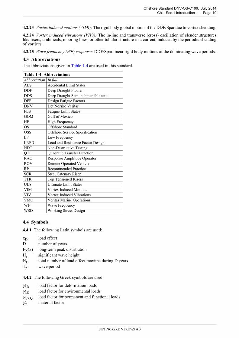
4.3 Abbreviations
The abbreviations given in Table 1-4 are used in this standard.
4.4 Symbols
4.4.1 The following Latin symbols are used:
4.4.2 The following Greek symbols are used:
Table 1-4 Abbreviations
Abbreviation In full
ALS Accidental Limit States
DDF Deep Draught Floater
DDS Deep Draught Semi-submersible unit
DFF Design Fatigue Factors
DNV Det Norske Veritas
FLS Fatigue Limit States
GOM Gulf of Mexico
HF High Frequency
OS Offshore Standard
OSS Offshore Service Specification
LF Low Frequency
LRFD Load and Resistance Factor Design
NDT Non-Destructive Testing
QTF Quadratic Transfer Function
RAO Response Amplitude Operator
ROV Remote Operated Vehicle
RP Recommended Practice
SCR Steel Catenary Riser
TTR Top Tensioned Risers
ULS Ultimate Limit States
VIM Vortex Induced Motions
VIV Vortex Induced Vibrations
VMO Veritas Marine Operations
WF Wave Frequency
WSD Working Stress Design
xD load effect
D number of years
FX(x) long-term peak distribution
Hs significant wave height
ND total number of load effect maxima during D years
Tp wave period
γf,D load factor for deformation loads
γf,E load factor for environmental loads
γf,G,Q load factor for permanent and functional loads
γm material factor

DET NORSKE VERITAS AS
Offshore Standard DNV-OS-C106, July 2014
Ch.1 Sec.1 Introduction – Page 11
5 Non-operational phases
5.1 General
5.1.1 In general the unit shall be designed to resist relevant loads associated with conditions that may occurduring all phases of the life-cycle of the unit. Such phases may include:
— fabrication— load-out and sea fastening— sea transportation (wet or dry)— assembly of hull main sections including lifting— installation (dynamic upending, launching, deck mating, jacking)— relocation (drilling mode, new site)— de-commissioning.
5.1.2 Structural design covering marine operations and construction sequences shall be undertaken inaccordance with DNV-OS-C101 for LRFD method or DNV-OS-C201 for WSD method.
5.1.3 Marine operations may be undertaken in accordance with the requirements stated in the VMO standard(ref. [4]).
5.1.4 All marine operations shall, as far as practicable, be based upon well proven principles, techniques,systems and equipment and shall be undertaken by qualified, competent personnel possessing relevantexperience.
5.1.5 Structural responses resulting from one temporary phase condition (e.g. construction or assembly, ortransportation) that may influence design criteria in another phase shall be clearly documented and consideredin all relevant design workings.
5.2 Fabrication
5.2.1 The planning of fabrication sequences and the methods of fabrication shall be performed. Loadsoccurring in fabrication phases shall be assessed and, when necessary, the structure and the structural supportarrangement shall be evaluated for structural adequacy.
5.2.2 Major lifting operations shall be evaluated to ensure that deformations are within acceptable levels, andthat relevant strength criteria are satisfied.
5.2.3 Fabrication residual; stresses due to welding and fitting must be within acceptable tolerance (see DNV-OS-C401) or otherwise accounted for in design analysis.
5.3 Mating
All relevant load effects incurred during mating operations shall be considered in the design process. Particularattention should be given to hydrostatic loads imposed during mating sequences.
5.4 Sea transportation
5.4.1 A detailed transportation assessment shall be undertaken which includes determination of the limitingenvironmental criteria, evaluation of intact and damage stability characteristics, motion response of the globalsystem and the resulting, induced load effects. The occurrence of slamming loads on the structure and theeffects of fatigue during transport phases shall be evaluated when relevant. Wind induced vortex sheddingshould be evaluated for truss and deck tubular members.
Guidance note:
Guidance on sea transportation is available in the DNV VMO rules.
---e-n-d---of---G-u-i-d-a-n-c-e---n-o-t-e---
5.4.2 Satisfactory compartmentation and stability during all floating operations shall be ensured.
5.4.3 All aspects of the transportation, including planning and procedures, preparations, sea-fastenings andmarine operations should comply with the requirements of the warranty authority.
5.5 Installation
5.5.1 Installation procedures of foundations (e.g. piles, suction anchor or gravity based structures) shallconsider relevant static and dynamic loads, including consideration of the maximum environmental conditionsexpected for the operations.
5.5.2 For novel installation activities, relevant model testing should be considered.
DET NORSKE VERITAS AS
Offshore Standard DNV-OS-C106, July 2014
Ch.1 Sec.1 Introduction – Page 12
5.5.3 The loads induced by the marine spread mooring involved in the operations, and the forces exerted onthe structures utilised in positioning the unit, such as fairleads and pad-eyes, shall be considered for localstrength checks.
Guidance note:
Guidance on offshore installation is available in the DNV VMO rules.
---e-n-d---of---G-u-i-d-a-n-c-e---n-o-t-e---
5.6 Decommissioning
Abandonment of the unit shall be planned for in the design stage.
DET NORSKE VERITAS AS
Offshore Standard DNV-OS-C106, July 2014
Ch.2 Sec.1 Structural categorisation, selection of material and extent of inspection – Page 13
CHAPTER 2 TECHNICAL CONTENT
SECTION 1 STRUCTURAL CATEGORISATION, SELECTION OF MATERIAL AND EXTENT OF INSPECTION
1 Introduction
1.1 General
1.1.1 Selection of materials and inspection principles shall be based on a systematic categorisation of thestructure according to the structural significance and the complexity of the joints or connections as given inDNV-OS-C101 Ch.2 Sec.3.
1.1.2 In addition to in-service operational phases, consideration shall be given to structural members anddetails utilised for temporary conditions, e.g. fabrication, lifting arrangements, towing and installationarrangements, etc.
1.1.3 The structural application categories are determined based on the structural significance, consequencesof failure and the complexity of the joints. The structural application category set the selection of steel qualityand the extent of inspection for the welds.
1.1.4 The steel grades selected for structural components are to be related to calculated stresses andrequirements for toughness properties and are to be in compliance with the requirements given in the DNV-OS-B101.
1.1.5 Special consideration shall be given to ensure the appropriate inspection category for welds with highutilisation in fatigue if the coverage with standard local area allocation is insufficient.
1.1.6 Examples of typical structural categories applicable to DDF are stated in [2]. These examples provideminimum requirements and are not intended to restrict the designer in applying more stringent requirementsshould such requirements be desirable.
2 Structural categorisation
Application categories for structural components are defined in DNV-OS-C101 Ch.2 Sec.3. Structuralmembers of a DDF unit are grouped as follows: However if a special design warrants redefining the categories,the same shall be discussed and agreed.
Special category
a) Portions of deck plating, heavy flanges, and bulkheads within the structure which receive majorconcentrated loads.
b) External shell structure (plating and stiffeners) in way of highly stressed connections (higher than 85% ofthe allowable i.e. at 0.85 usage factor) to the deck structure.
c) Major intersections of bracing members.
d) External brackets, portions of bulkheads, and frames which are designed to receive concentrated loads atintersections of major structural members.
e) Highly stressed elements of anchor line fairleads, crane pedestals, flare boom, etc. and their supportingstructure.
For Spars, these special structural categories include the hard tank to deck leg and to truss leg connections, thetruss to soft tank connections, the heave plate to truss leg connections, truss tubular joints, the fairlead and chainjack foundations, and the riser frame to hard tank connections.
For DDS units, these special structural categories include “through” material used at connections of verticalcolumns, upper platform decks and upper or lower hulls which are designed to provide alignment and adequateload transfer, i.e. the pontoon to column connection, column to deck connection, any brace to columnconnections and connection of heave damping structure to main hull structure.
Primary category
a) Deck plating, heavy flanges, transverse frames, stringers, and bulkhead structure that do not receive majorconcentrated loads (not categorized as special).
b) Moonpool shell.
c) External shell structure of vertical columns, lower and upper hulls, and diagonal and horizontal braces.

DET NORSKE VERITAS AS
Offshore Standard DNV-OS-C106, July 2014
Ch.2 Sec.1 Structural categorisation, selection of material and extent of inspection – Page 14
d) Bulkheads, decks, stiffeners and girders that provide local reinforcement or continuity of structure in wayof intersections, except areas where the structure is considered special application.
e) Main support structure of heavy substructures and equipment, e.g. anchor line fairleads, cranes, drill floorsubstructure, lifeboat platform, thruster well and helicopter deck.
For Spars, primary structures include hull shell, top spar deck and bottom deck structures, hull ring frames,longitudinal stringers and web frames, all radial bulkheads, truss chords and brace members, heave plate andsoft tank structures.
For DDS units, the heave damping structure is considered primary structure.
Secondary category
a) Upper platform decks, or decks of upper hulls except areas where the structure is considered primary orspecial application.
b) Bulkheads, stiffeners, flats or decks and girders, diagonal and horizontal bracing, which are not consideredas primary or special application.
c) Non-watertight bulkheads internal outfitting structure in general, and other non-load bearing components.
d) Deckhouses.
For Spars, secondary structures include; e.g., all internal hull flats, soft tank shell and internal bulkheads withno pressure differential, and hull and heave plate stiffeners and soft tank stiffeners.
3 Material selection
3.1 General
3.1.1 Material specifications shall be established for all structural materials utilised in a DDF unit. Suchmaterials shall be suitable for their intended purpose and have adequate properties in all relevant designconditions. Material selection shall be undertaken in accordance with the principles given in DNV-OS-C101.
3.1.2 When considering criteria appropriate to material grade selection, adequate consideration shall be givento all relevant phases in the life cycle of the unit. In this connection there may be conditions and criteria, otherthan those from the in-service, operational phase, that may govern the design requirements with respect to theselection of material. (Such criteria may, for example, be design temperature and/or stress levels during marineoperations.)
3.1.3 In structural cross-joints essential for the overall structural integrity where high tensile stresses are actingnormal to the plane of the plate, the plate material shall be tested to prove the ability to resist lamellar tearing(Z-quality).
3.1.4 Material designations are defined in DNV-OS-C101.
3.2 Design temperature
3.2.1 External structures above the inspection waterline are to be designed for service temperatures down tothe lowest mean daily temperature for the area(s) where the unit is to operate.
3.2.2 External structures below the inspection waterline need normally not be designed for servicetemperatures lower than 0°C.
3.2.3 Internal structures are assumed to have the same service temperature as the adjacent external structure ifnot otherwise documented.
3.2.4 Internal structures in way of permanently heated rooms need normally not be designed for servicetemperatures lower than 0°C.
4 Inspection categories
4.1 General
4.1.1 Welding, and the extent of non-destructive examination during fabrication, shall be in accordance withthe requirements stipulated for the structural categorisation designation as defined in DNV-OS-C101 Ch.2Sec.3.
4.1.2 Inspection categories determined in accordance with DNV-OS-C101 provide requirements for theminimum extent of required inspection. When considering the economic consequence that repair during in-service operation may entail, for example, in way of complex connections with limited or difficult access, itmay be considered prudent engineering practice to require more demanding requirements for inspection thanthe required minimum.

DET NORSKE VERITAS AS
Offshore Standard DNV-OS-C106, July 2014
Ch.2 Sec.1 Structural categorisation, selection of material and extent of inspection – Page 15
4.1.3 When determining the extent of inspection and the locations of required NDT, in additional to evaluatingdesign parameters (for example fatigue utilisation), consideration should be given to relevant fabricationparameters including:
— location of block (section) joints— manual versus automatic welding— start and stop of weld etc.
5 Guidance to minimum requirements
Figure 1-1, Figure 1-2, Figure 1-3, Figure 1-4 and Figure 1-5 illustrates minimum requirements for selectionof the structural category for one example of structural configurations of a DDF unit. The indicated structuralcategorisation should be regarded as guidance of how to apply the recommendations in DNV-OS-C101.
Figure 1-1 Example of structural categorisation (Special and Primary Steel) in the hard tank area of a typical Spar

DET NORSKE VERITAS AS
Offshore Standard DNV-OS-C106, July 2014
Ch.2 Sec.1 Structural categorisation, selection of material and extent of inspection – Page 16
Figure 1-2 Example of structural categorisation (Special and Primary Steel) in the soft tank/hard tank and Trussinterface of a typical Spar
Figure 1-3 Example of structural categorisation of a column and pontoon connection of a typical Deep DraughtSemi
Special
Soft Tank
Truss
Primary

DET NORSKE VERITAS AS
Offshore Standard DNV-OS-C106, July 2014
Ch.2 Sec.1 Structural categorisation, selection of material and extent of inspection – Page 17
Figure 1-4 Example of structural categorisation of deck and column connection of a typical Deep Draught Semi
Figure 1-5 Example of structural categorisation of heave damping structure of a typical DDF
DET NORSKE VERITAS AS
Offshore Standard DNV-OS-C106, July 2014
Ch.2 Sec.2 Design loads – Page 18
SECTION 2 DESIGN LOADS
1 General
1.1 Objective
The objective of this section is to provide additional load provisions to DDF units not covered within DNV-OS-C101.
1.2 Application
Load descriptions are intended to cover operational as well as non-operational phases for the three limit states(ULS, FLS and ALS).
2 Permanent loads
2.1 Permanent ballast
The type and use of permanent ballast (e.g. within soft tank of DDF units) for stability reasons must be carefullyevaluated with respect to long term effects related to corrosion, wash out etc.
3 Variable functional loads
3.1 Hydrostatic pressures
3.1.1 For Spars, all relevant combinations of tank filling in the hard tank for the installation and operationalphases shall be taken into account in design.
3.1.2 For Deep Draught Semis, all relevant combinations of tank filling in the columns, pontoons and/or heavedamping structure in the installation and operational phases shall be taken into account in design.
3.1.3 Hydrostatic or hydrodynamic differential pressures acting on the hull or buoyancy tanks during launchand upending sequences, mating, ballasting sequences, whichever is relevant, shall be analysed or determinedand taken into account in design of the hull.
3.2 Differential pressures
All relevant combinations of differential pressures due to filling of ballast tanks, produced fluids, compressedair etc. shall be taken into account in design.
4 Environmental loads
4.1 Environmental conditions
4.1.1 If sufficient environmental data is available, environmental joint probability models may be developedand applied in the design of DDF units. This is especially important in regions with e.g. high loop current andfrequently occurring hurricanes.
4.1.2 In geographical areas with hurricane activity, special considerations have to be made with respect to theselection of relevant sea states to be applied in design of the unit. (E.g. new Meteocean criteria (API BUL.INT2/- MET) with updated GOM criteria published in May 2007).
4.1.3 Due to the geometry (deep draught and large volume) of DDF units the current loading may be of highimportance for design of mooring or riser systems in relation to vortex induced vibrations (VIV) for e.g. hulland risers. Hence attention must be given to the description of magnitude and direction of current with depth.
4.2 Determination of characteristic loads
4.2.1 Calculation of characteristic hydrodynamic loads may be carried out according to DNV-RP-C205.
4.2.2 Hydrodynamic model tests should be carried out to:
— confirm that no important hydrodynamic features have been overlooked (for new type of units,environmental conditions, adjacent structures, Mathieu instability etc.)
— support theoretical calculations when available analytical methods are susceptible to large uncertainties(e.g. in evaluating the need for VIM suppression strakes, on DDF hull)
— verify theoretical methods or models on a general basis.

DET NORSKE VERITAS AS
Offshore Standard DNV-OS-C106, July 2014
Ch.2 Sec.2 Design loads – Page 19
4.2.3 Wind tunnel tests should be performed when:
— wind loads are significant for overall stability, motions or structural response— there is a danger of dynamic instability.
4.2.4 Models applied in model tests shall be sufficient (reasonable scale and controllable scaling effects) torepresent the actual unit. The test set-up and registration system shall provide a sound basis for reliable andrepeatable interpretations.
4.2.5 A correlation report (tests and calculations) shall be prepared for validation purposes (designdocumentation).
4.3 Hydrodynamic loads
4.3.1 Resonant excitation (e.g. internal moonpool resonance, sloshing and roll/pitch resonance) shall becarefully evaluated. Wave on deck via moonpool has to be considered for DDF concepts with relatively shortdistances between moonpool and the outer wave active zone.
4.3.2 If hydrodynamic analyses of a DDF are performed with the moonpool 'sealed' at the keel level it must bevalidated that the results are equivalent to 'open' DDF hydrodynamic analyses. Special focus should be placedon the heave motion prediction (important for riser system) by using consistent added mass, total damping andexcitation forces such that the Eigen period and response in heave can be determined correctly.
4.3.3 In case of a DDF with damping and added mass heave plates and where it is possible that resonant, ornear resonant heave motion may occur, the theoretical predictions should be validated against model testresults.
4.3.4 If VIM suppression devices (e.g. spiral strakes) are attached to the hull, the increased loads (drag, inertia)must be taken into account. This applies to the operational as well as non-operational phases.
4.3.5 Air gap and green water (Wave-on-Deck) are to be considered. (See DNV-OS-C101 or DNV-OS-C201).
4.3.6 Air gap is measured to the bottom of the deck structure.
4.3.7 Simulation of loads and responses on risers in the moonpool area shall be carried out according to arecognised code.
Guidance note:
DNV-OS-F201 may be applied for this purpose.
---e-n-d---of---G-u-i-d-a-n-c-e---n-o-t-e---
4.4 Combination of environmental loads
4.4.1 In areas with high current (e.g. loop current, or high subsurface current) special attention must be givento the joint occurrence of wind, waves and current. Joint probability models (loads and load effects) arerecommended.
4.4.2 If more accurate data are not available, the combination of environmental loads may be taken accordingto DNV-OS-C101 Ch.2 Sec.2.

DET NORSKE VERITAS AS
Offshore Standard DNV-OS-C106, July 2014
Ch.2 Sec.3 Load effects – Page 20
SECTION 3 LOAD EFFECTS
1 General
1.1 Objective
The objective of this section is to provide additional load effect provisions to DDF units not covered withinDNV-OS-C101.
1.2 Application
Load effect descriptions are intended to cover operational as well as non-operational phases for the three limitstates (ULS, FLS and ALS).
2 Load effect analysis in the operational phase
2.1 General
2.1.1 Global dynamic motion response analysis taking into account loads from wind (static and gust), waves(wave frequency and low frequency) and current shall be performed. Time domain analysis is the preferredoption as opposed to frequency domain type analysis. However, frequency domain analysis may be acceptableif proper justification is demonstrated. Reference is made to DNV-RP-F205 for detailed description of globalperformance analysis procedures.
2.1.2 Coupled analyses may be performed for DDF units in order to determine the coupling effects due to thepresence of mooring and risers. These coupled analyses mainly provide viscous damping estimates for slowlyvarying motions (all six degrees of freedom). When utilising viscous damping estimates from coupled analysesthe actual riser installation program must be taken into consideration.
2.1.3 The simulation length for determination of the different load effects must be sufficient such that reliableextreme response statistics can be obtained.
Guidance note:
Combined loading.
Common practice to determine extreme responses has been to expose the dynamic system to multiple stationarydesign environmental conditions. Each design condition is then described in terms of a limited number ofenvironmental parameters (e.g. Hs, Tp) and a given seastate duration (3 to 6 hours). Different combinations of wind,wave and current with nearly the same return period for the combined environmental condition are typically applied.
The main problem related to design criteria based on environmental statistics is that the return period for thecharacteristic load effect is unknown for non-linear dynamic systems. This will in general lead to an inconsistentsafety level for different design concepts and failure modes.
A more consistent approach is to apply design based on response statistics. Consistent assessment of the D-year loadeffect will require a probabilistic response description due to the long-term environmental loads on the system. Theload effect with a return period of D-year, denoted xD, can formally be found from the long-term load effectdistribution as:
FX(xD) = 1 - 1/ND
ND = total number of load effect maxima during D years
FX(x) = long-term peak distribution of the (generalised) load effect
The main challenge related to this approach is to establish the long-term load effect distribution due to the non-linearbehaviour. Design based on response statistics is in general the recommended procedure and should be consideredwhenever practicable for consistent assessment of characteristic load effects. Further details may be found inAppendices to DNV-OS-F201.
---e-n-d---of---G-u-i-d-a-n-c-e---n-o-t-e---
2.2 Global bending effects
2.2.1 Global bending and shear forces along the length of the structure due to environmental load effects shallbe determined. This applies to first order wave effects, as well as P-delta effects due to platform heel or tilt.
2.2.2 Global bending and shear forces in the hull will be influenced by the non-linear restoring effect from themooring system. This additional load effect shall be analysed and taken into account in design of the hullstructure.

DET NORSKE VERITAS AS
Offshore Standard DNV-OS-C106, July 2014
Ch.2 Sec.3 Load effects – Page 21
3 Load effect analysis in the non operational phases
3.1 General
3.1.1 All temporary phases shall be carefully evaluated and sufficient level and amount of analyses shall beperformed according to this standard. Further details regarding non-operational conditions may be found inDNV's VMO standard.
3.1.2 Relevant model testing should be considered for novel installation procedures.
3.1.3 Stability check and ballast capacity design shall include assessment of relevant load conditions duringtransport and installation.
3.2 Load-out and transportation
3.2.1 Hull/deck stresses during load-out are to be evaluated and accounted for in the design. Possible skidbeam foundation settlement should be minimized or avoided. Local sea fastening stresses are to be kept withinacceptable design limits.
3.2.2 In case of wet tow in harsh environment (e.g. overseas), model tests shall be performed as a supplementto motion response analyses. Non-linear effects (e.g. slamming, global bending or shear, green seas) shall betaken into account.
3.2.3 Motion response analyses shall be performed for dry transports on e.g. heavy lift vessel, or barge. Specialattention shall be made to:
— roll motions (roll angles, accelerations, viscous roll damping)
— slamming pressures and areas and structural responses due to slamming
— global strength (vessel, DDF/Spar unit)
— strength of sea-fastening
— wind VIV of slender truss members.
— stability, overhang.
3.3 Launching
Launching may be an alternative way of installation or upending a Spar (e.g. truss spar). Model testing of thelaunch process may be required if there is limited or no experience with such operations for similar concepts.
3.4 Deck mating
3.4.1 Offshore installation of deck structure and modules will require refined analyses in order to determinethe governing responses. This applies to lifting operations as well as float-over operations with barge.Important factors are limiting environmental criteria, impact responses and floating stability requirements.
3.4.2 Floating concepts (“jack-up”) utilising jacking of legs to desired draught and subsequent deballasting toobtain sufficient air-gap, shall be carefully evaluated or analysed with respect to limiting environmentalcriteria.
3.5 Upending
3.5.1 Pre-upending phases shall be analysed with respect to global bending moments and shear forces in thehull. In case that wave load effects in this pre-upending phase may be relevant, this shall be analysed and takeninto account.
3.5.2 In case of dynamic upending, analyses shall be performed in order to determine global and local loadeffects in the DDF/Spar unit and its appurtenances.
3.5.3 Hydrostatic or hydrodynamic differential (outside/inside) pressures during dynamic upending shall bedetermined and further used in design of the hull structure.
3.5.4 Model testing of the dynamic upending may be avoided if the applied simulation software has beenvalidated against similar or relevant operations demonstrating good correlation.
3.5.5 In case of lift assisted upending offshore, the limiting environmental criteria must be carefully selected.Dynamic analyses of the system (i.e. lift vessel, lifting gear, Spar unit) will be required in order to determineresponses in lifting gear and DDF/Spar unit.

DET NORSKE VERITAS AS
Offshore Standard DNV-OS-C106, July 2014
Ch.2 Sec.4 Ultimate limit states (ULS) – Page 22
SECTION 4 ULTIMATE LIMIT STATES (ULS)
1 General
1.1 Objective
1.1.1 General considerations in respect to methods of analysis and capacity checks of structural elements aregiven in DNV-OS-C101 for LRFD and DNV-OS-C201 for WSD.
1.1.2 This section applies for the hull and deck or modules and operational as well as non-operational phases.
1.1.3 The LRFD format shall be used when the ULS capacity of the structure is checked. Two combinationsshall be checked, a) and b). The load factors are defined in DNV-OS-C101 Ch.2 Sec.1 [4.4] and values aregiven in Table 4-1.
1.1.4 The loads shall be combined in the most unfavourable way, provided that the combination is physicallyfeasible and permitted according to the load specifications. For permanent loads, a load factor of 1.0 in loadcombination a) shall be used where this gives the most unfavourable response. Other considerations for thepartial coefficients and design loads are given in DNV-OS-C101 Ch.2 Sec 1 and 2, respectively.
1.1.5 The material factor γm for ULS yield check should be 1.15 for steel. The material factor γm for ULSbuckling check is given in DNV-OS-C101 Ch.2 Sec.4.
1.2 Methodology and acceptance criteria
The LRFD methodology and the acceptance criteria for the ULS check are given in DNV-OS-C101.
2 Hull
2.1 Operational phase
2.1.1 For global structural analysis, a complete three-dimensional structural model of the unit is required. Thismay be a complete shell type model, or a combined shell or space-frame model.
2.1.2 Additional detailed finite element analyses may be required for complex joints and other complicatedstructural parts especially at interfaces and connections to determine the local stress distribution moreaccurately. Typical examples being: hull interface with mooring system, hard tank area, column and braceconnections, strake terminations or interactions, deck and hull connections, hull interface with riser system,pontoon to column connection, brace to column connection, column to deck connection.
Guidance note:
For Spars, in order to be able to assess the effect of all possible tank filling configurations, a local finite element modelcovering the hard tank area may be utilised. Only those tanks used in the normal operation of the platform shall as aminimum be modelled. The stresses from a local finite element model should be superimposed to global stresses.
For DDS units, reference is made to DNV-OS-C103.
---e-n-d---of---G-u-i-d-a-n-c-e---n-o-t-e---
2.1.3 The additional global bending and shear due to P-delta and mooring restoring effects are to be combinedwith first order wave effects in a consistent way.
2.1.4 The same applies to combining the loads from the risers on riser frames in the moonpool and transferinto the hull structure. Horizontal forces as well as vertical (friction from riser system) shall be taken intoaccount.
2.1.5 If VIV suppression devices (e.g. strakes) are installed, both local (direct wave or current loads) andglobal bending effects should be considered in design of the suppression devices.
Table 4-1 Load factors – ULS
Combination of design loads
Load categories
Permanent and variable functional loads,
γf,G,Q
Environmental loads,γf,F
Deformation loads,γf,D
a) 1.3 1) 0.7 1.0
b) 1.0 1.3 1.0
1) If the load is well defined e.g. masses or functional loads with great confidence, no possible overfilling of tanks etc. the coefficient may be reduced to 1.2.
DET NORSKE VERITAS AS
Offshore Standard DNV-OS-C106, July 2014
Ch.2 Sec.4 Ultimate limit states (ULS) – Page 23
2.2 Non-operational phases
2.2.1 Finite element analyses are to be performed for long international water wet tow and dry tow in harshenvironment.
2.2.2 For dry tow this implies that the complete structural system (hull sections, sea-fastening, transportvessel) shall be modelled such that reliable stress-distributions can be obtained.
2.2.3 For wet tow in harsh environment special emphasis must be put on the simulation or modelling of thehydrodynamic wave pressures or accelerations acting on the wet hull structure. Further, the non-linear hoggingand sagging bending or shear effects due to the shape of the hull should be properly simulated or accounted forin the design.
2.2.4 For Spars, the level or amount of finite element analyses for the upending process needs to be evaluated.As a minimum, the following considerations shall be made:
a) Operational Global bending moments and shear forces are to be compared (location and level) with thosefor pre-upending and dynamic upending.
b) Possibilities for local and global buckling (e.g. skirt area for a classic spar) due to global load effects andlateral differential pressures needs to be assessed/analysed.
2.2.5 For DDS units, the finite element analysis shall cover all critical transient phases during installation.
3 Deck or topside
3.1 Operation phase
3.1.1 Structural analysis of deck structure shall, in general, follow the same principles as outlined for the hull.
3.1.2 Horizontal accelerations at deck level due to wave loading will be high for some DDF units in harshenvironment. Detailed finite element analyses of the deck and hull connections shall be performed in suchinstances.
3.2 Non-operational phases
Typical non-operational phases as fabrication, transportation and installation of deck and topside modules shallbe assessed and analysed to a sufficient level such that the actual stress level can be determined and used in thedesign checks.
4 Minimum scantlings
Minimum scantlings for plate, stiffeners and girders are given in DNV-OS-C101 Ch.2 Sec.4.

DET NORSKE VERITAS AS
Offshore Standard DNV-OS-C106, July 2014
Ch.2 Sec.5 Fatigue limit states (FLS) – Page 24
SECTION 5 FATIGUE LIMIT STATES (FLS)
1 General
1.1 General
1.1.1 The objective of this section is to provide supplemental guidance related to FLS design as outlined inDNV-OS-C101 Ch.2, Sec.5.
1.1.2 This section applies for the hull and deck or modules and major structural interfaces for operational aswell as non-operational phases.
1.1.3 In general, all significant stress fluctuations (operational and temporary phases) which contribute tofatigue damage in parts of the unit shall be taken into account for the FLS condition.
1.1.4 Criteria related to DFF’s are given in DNV-OS-C101 Ch.2 Sec.5.
1.1.5 DNV-RP-C203 presents recommendations in relation to fatigue analyses based on fatigue tests andfracture mechanics.
2 Hull
2.1 Operation phase
2.1.1 First order wave loads will usually be the dominating fatigue component for the hull. The long termdistribution of wave induced stress fluctuations need to be determined with basis in the same type of load effectand finite element analyses as for ULS.
Guidance note:
Early phase evaluation or analysis of fatigue may incorporate modelling the hull as a beam with associated massdistribution and simulation of wave loads according to Morison formulation, or preferably, performing a radiation ordiffraction analysis.
Final documentation related to first order wave induced fatigue damage should incorporate a stochastic approach. Thisimplies establishing stress transfer functions, which are combined with relevant wave spectra (scatter diagram) inorder to obtain long-term distribution of stresses. The stress transfer functions should be obtained from finite elementanalyses with appropriate simulation of wave loads (radiation/diffraction analysis). The P-delta effect due to platformroll and pitch shall be taken into account.
---e-n-d---of---G-u-i-d-a-n-c-e---n-o-t-e---
2.1.2 As for ULS, the P-delta effect due to platform roll or pitch shall be taken into account. This implies thatboth first order and second order, slowly varying roll or pitch motions need to be considered and taken intoaccount if contributing to fatigue damage in the hull.
2.1.3 For special fatigue sensitive areas, local stress concentrations shall be determined by detailed finiteelement analyses.
2.1.4 Typical fatigue sensitive areas for DDF units include:
— hull and deck connections— collision ring area— hull and deck and stiffener connections at location of peak wave induced global bending moments— hull and mooring system interface— hard tank area— column and brace connections— strake and hull connections and strake terminations— riser frame/support and hull connections— openings in main hull— flare tower— mooring and export/import SCR connections— hard tank and truss connections— tubular joints— column to deck connections— column to pontoon connections— tensioner support structure.
2.1.5 Fatigue analyses shall be performed to check that the hull strakes have sufficient fatigue lives. Relativemotions between the hull and disturbed wave kinematics around strakes must be properly taken into account.Hydrodynamic pressures from a radiation/diffraction analysis in combination with a Morison formulation(inertia and drag) will be sufficient to describe the environmental loads on the strakes.
DET NORSKE VERITAS AS
Offshore Standard DNV-OS-C106, July 2014
Ch.2 Sec.5 Fatigue limit states (FLS) – Page 25
2.1.6 VIM load effects from mooring system (global hull in-line and cross-flow motions) into the fairlead orhull areas shall be outlined and taken into account if significant. The same applies to VIV load effects fromriser system into the riser frame or hull areas.
2.1.7 For mooring fairlead/riser porch analysis, the effect of disturbed wave field due to the presence ofcolumns, etc. should also be taken into account.
2.1.8 Allowance for wear and tear shall be taken into account in areas exposed to for example friction andabrasion. For a DDF unit this will typically be interfaces between hull and risers (keel level, intermediate riser-frames, deck level). These relative motions are caused by movements of the unit and risers and subsequentpullout and push-up of the risers in the moonpool.
2.1.9 The fatigue analysis of riser / keel guide frames shall account for the interaction between risers and guideframes where relevant.
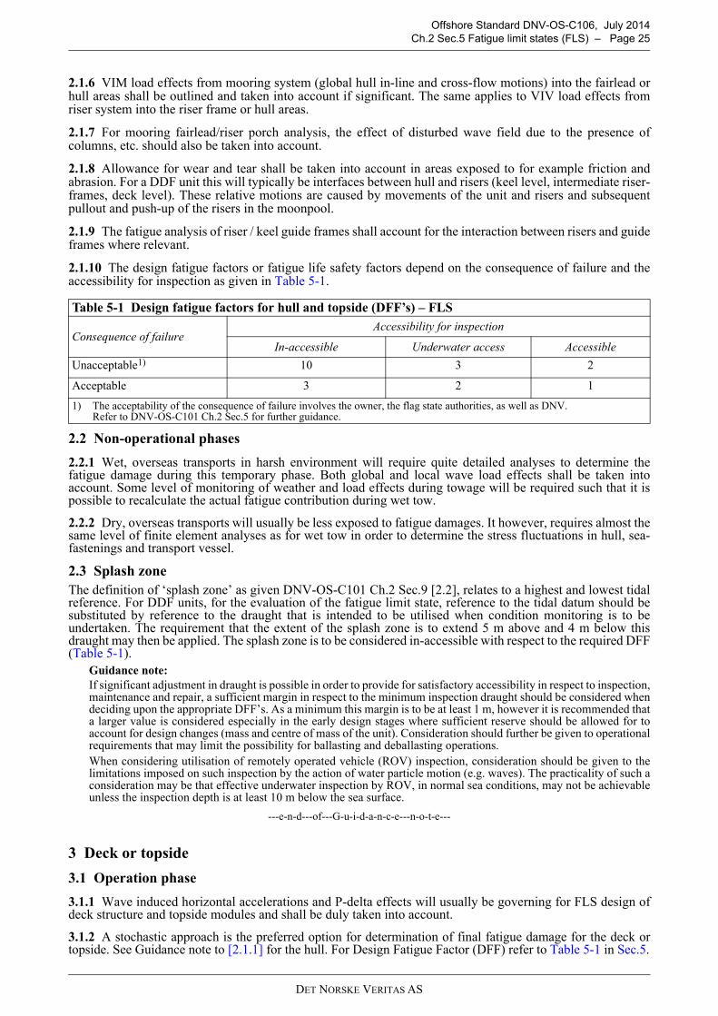
2.1.10 The design fatigue factors or fatigue life safety factors depend on the consequence of failure and theaccessibility for inspection as given in Table 5-1.
2.2 Non-operational phases
2.2.1 Wet, overseas transports in harsh environment will require quite detailed analyses to determine thefatigue damage during this temporary phase. Both global and local wave load effects shall be taken intoaccount. Some level of monitoring of weather and load effects during towage will be required such that it ispossible to recalculate the actual fatigue contribution during wet tow.
2.2.2 Dry, overseas transports will usually be less exposed to fatigue damages. It however, requires almost thesame level of finite element analyses as for wet tow in order to determine the stress fluctuations in hull, sea-fastenings and transport vessel.
2.3 Splash zone
The definition of ‘splash zone’ as given DNV-OS-C101 Ch.2 Sec.9 [2.2], relates to a highest and lowest tidalreference. For DDF units, for the evaluation of the fatigue limit state, reference to the tidal datum should besubstituted by reference to the draught that is intended to be utilised when condition monitoring is to beundertaken. The requirement that the extent of the splash zone is to extend 5 m above and 4 m below thisdraught may then be applied. The splash zone is to be considered in-accessible with respect to the required DFF(Table 5-1).
Guidance note:
If significant adjustment in draught is possible in order to provide for satisfactory accessibility in respect to inspection,maintenance and repair, a sufficient margin in respect to the minimum inspection draught should be considered whendeciding upon the appropriate DFF’s. As a minimum this margin is to be at least 1 m, however it is recommended thata larger value is considered especially in the early design stages where sufficient reserve should be allowed for toaccount for design changes (mass and centre of mass of the unit). Consideration should further be given to operationalrequirements that may limit the possibility for ballasting and deballasting operations.
When considering utilisation of remotely operated vehicle (ROV) inspection, consideration should be given to thelimitations imposed on such inspection by the action of water particle motion (e.g. waves). The practicality of such aconsideration may be that effective underwater inspection by ROV, in normal sea conditions, may not be achievableunless the inspection depth is at least 10 m below the sea surface.
---e-n-d---of---G-u-i-d-a-n-c-e---n-o-t-e---
3 Deck or topside
3.1 Operation phase
3.1.1 Wave induced horizontal accelerations and P-delta effects will usually be governing for FLS design ofdeck structure and topside modules and shall be duly taken into account.
3.1.2 A stochastic approach is the preferred option for determination of final fatigue damage for the deck ortopside. See Guidance note to [2.1.1] for the hull. For Design Fatigue Factor (DFF) refer to Table 5-1 in Sec.5.
Table 5-1 Design fatigue factors for hull and topside (DFF’s) – FLS
Consequence of failureAccessibility for inspection
In-accessible Underwater access Accessible
Unacceptable1) 10 3 2
Acceptable 3 2 1
1) The acceptability of the consequence of failure involves the owner, the flag state authorities, as well as DNV. Refer to DNV-OS-C101 Ch.2 Sec.5 for further guidance.
DET NORSKE VERITAS AS
Offshore Standard DNV-OS-C106, July 2014
Ch.2 Sec.5 Fatigue limit states (FLS) – Page 26
3.1.3 Deck and hull connections, joints in deck structure, module supports etc. will typically be fatiguesensitive areas. The amount or level of detailed finite element analyses for these joints needs to be considered.For the deck and hull connection some level or amount of detailed finite element analyses shall be performed,at least for units located in harsh environment.
3.2 Non-operational phases
Fatigue damage of deck structure and topside modules shall be documented if the stress fluctuations in thedifferent phases are significant.
DET NORSKE VERITAS AS
Offshore Standard DNV-OS-C106, July 2014
Ch.2 Sec.6 Accidental limit states (ALS) – Page 27
SECTION 6 ACCIDENTAL LIMIT STATES (ALS)
1 General
1.1 Objective
1.1.1 The objective of this section is to provide supplemental guidance related to ALS design as outlined inDNV-OS-A101 and in DNV-OS-C101 Ch.2 Sec.6.
1.1.2 This section applies for the hull and deck or modules and operational as well as non-operational phases.
1.1.3 General requirements concerning accidental events are given in DNV-OS-C101.
2 General requirements
Units shall be designed to be damage tolerant, i.e. credible accidental damages, or events, should not cause lossof global structural integrity or stability. The capability of the structure to redistribute loads should beconsidered when designing the structure. Hull compartmentation should not allow loss of unit with one or morecompartments flooded (see DNV-OS-A101).
3 Fire
Deck area will be limited for some DDF/Spar concepts. Potential fire scenarios shall therefore be carefullyconsidered and taken into account in design and layout planning.
4 Explosion
4.1 General
4.1.1 As for fire, the limiting deck space and protected moon-pool area (potential gas or oil leakage) for someDDF units require that explosions are carefully considered in the design process.
4.1.2 In respect to design considering loads resulting from explosions, or a combination of the following maindesign philosophies are relevant:
— ensure that the probability of explosion is reduced to a level where it is not required to be considered as arelevant design load case
— ensure that hazardous areas are located in unconfined (open) locations and that sufficient shieldingmechanisms (e.g. blast walls) are installed
— locate hazardous areas in partially confined locations and design utilising the resulting, relatively smalloverpressures
— locate hazardous areas in enclosed locations and install pressure relief mechanisms (e.g. blast panels) anddesign for the resulting overpressure.
4.1.3 As far as practicable, structural design accounting for large plate field rupture resulting from explosionloads should normally be avoided due to the uncertainties of the loads and the consequence of the rupture itself.
4.1.4 Structural support of blast walls, and the transmission of the blast load into main structural members shallbe evaluated when relevant. Effectiveness of connections and the possible outcome from blast, such as flyingdebris, shall be considered.
5 Collision
5.1 General
5.1.1 Safety assessments will be the basis for determination of type and size of colliding vessel and impactspeed.
5.1.2 Collision impact shall be considered for all elements of the unit, which may be impacted by supply vesselon sideways, bow or stern collision. The vertical extent of the collision zone shall be based on the depth anddraught of attending vessels and the relative motion between the attending vessels and the unit.
5.1.3 Resistance to unit collisions may be accounted for by indirect means, such as, using redundant framingconfigurations, collision ring in splash zone and materials with sufficient toughness in affected areas.
5.1.4 Boat landings are to be designed to withstand probable impact loads depending on the design servicevessels and the operational criteria. (see DNV-RP-C204).
DET NORSKE VERITAS AS
Offshore Standard DNV-OS-C106, July 2014
Ch.2 Sec.6 Accidental limit states (ALS) – Page 28
6 Dropped objects
6.1 General
6.1.1 Critical areas for dropped objects shall be determined on the basis of the actual movement of potentialdropped objects (e.g. crane actions) relative to the structure of the unit itself. Where a dropped object is arelevant accidental event, the impact energy shall be established and the structural consequences of the impactassessed.
6.1.2 Generally, dropped object assessment will involve the following considerations:
a) Assessment of the risk and consequences of dropped objects impacting topside, wellhead, riser system inmoon-pool and safety systems and equipment. The assessment shall identify the necessity of any localstructural reinforcement or protections to such arrangements.
b) Assessments of the risk and consequences of dropped objects impacting externally on the hull structure(shell, or bracings) and hull attachments such as strakes, fairleads and pipes. The structural consequencesare normally fully accounted for by the requirements for watertight compartmentation and damage stabilityand the requirement for structural redundancy of slender structural members.
7 Unintended flooding
7.1 General
7.1.1 A procedure describing actions to be taken after relevant unintended flooding shall be prepared.Unintended filling of hard tanks, collision ring and bracings for a DDF will be the most relevant scenarios forthe operation phase.
7.1.2 It must be ensured that counter-filling of tanks and righting up the unit can be performed safely andwithout delays.
7.1.3 Structural aspects related to the tilted condition and counter-flooding (if relevant) shall be investigated.This applies to the complete unit including risers and mooring system.
7.1.4 If the unit can not be brought back to the design draught and verticality by counter-ballasting andredistribution of ballast water, this must be taken into account in design of the unit.
7.1.5 The structure should be designed to withstand one compartment flooding under reduced environment(e.g. 10-yr return probability).
8 Riser damage
Provisions for accidental limit state design of risers, in general, are provided in DNV-OS-F201. Specialconsiderations for risers on DDF/Spar include, but are not limited to:
— The structural and global performance design should account for one tensioner cylinder out of service. — Loss of buoyancy, e.g. air cans for spar units.— Loss of station keeping, e.g. mooring line failure, or tendon failure.— Clashing between risers and/or umbilicals, and interaction between risers and surrounding structures.
9 Abnormal wave and wind events
9.1 General
9.1.1 Abnormal wave effects are partly related to air-gap and wave exposure of deck or topside structures aswell as tensioner system. Consequences from such wave impacts shall be evaluated and taken into account indesign of the relevant structural parts.
9.1.2 In hurricane environments the derrick tie down to the substructure and the top deck should be carefullydesigned. (see API Bulletin 2TD). The use of LRFD method for the design against uplift loads at the clampedfooting connections is recommended.
9.1.3 In areas with hurricanes, special considerations have to be made with respect to effects of load hysteresisand high cycle fatigue especially for moorings and deck mounted tall structures (e.g., derricks).
9.1.4 Hurricane loading is considered abnormal only in cases where the occurrence probability is consistentwith 10-4 annual level or if the unit is designed to be evacuated ahead of hurricanes and the damage isconsidered acceptable.
DET NORSKE VERITAS AS
Offshore Standard DNV-OS-C106, July 2014
Ch.2 Sec.7 Serviceability limit states (SLS) – Page 29
SECTION 7 SERVICEABILITY LIMIT STATES (SLS)
1 General
1.1 Objective
The objective of this section is to provide supplemental guidance related to SLS design as outlined in DNV-OS-C101 Ch.2 Sec.7. Since all partial load and material factors are equal to unity, the methodology asdescribed is also a WSD design procedure.
1.2 Criteria
1.2.1 The SLS calculations should include expected values of permanent and variable loads and specificdesign environmental conditions and deformation extreme expected values.
1.2.2 The maximum allowable deflections or hull displacements or motions are to be assessed as given inDNV-OS-C101 Ch.2 Sec.7 and any additional relevant operational limitations for essential systems /equipment.

DET NORSKE VERITAS AS
Offshore Standard DNV-OS-C106, July 2014
Ch.2 Sec.8 Weld connections – Page 30
SECTION 8 WELD CONNECTIONS
1 General
1.1 Objective
1.1.1 The objective of this section is to provide supplemental guidance related to weld connections design asoutlined in DNV-OS-C101 Ch.2 Sec.8 and DNV-OS-C201 Ch.2 Sec.8 for LRFD- or WSD-method, respectively.
1.1.2 The weld material factor γMw shall be taken as 1.3 in the LRFD design method.
1.2 Special connections
1.2.1 Special DDF/Spar welded connections that should receive more detailed scrutiny include the TTRfoundations in the centre well, the deck leg connections to the top of the spar deck, the hard tank bottomconnection to the truss legs, the heave plates connections to the truss, the soft tank to truss connections, deckto column, column to pontoon and heave damping structure to main hull.
1.2.2 Special connections, for example, grouted connections shall be fully qualified. The process as presentedin DNV-RP-A203 Qualification of New Technology can be used.

DET NORSKE VERITAS AS
Offshore Standard DNV-OS-C106, July 2014
Ch.2 Sec.9 Corrosion control – Page 31
SECTION 9 CORROSION CONTROL
1 Venue
Design Requirements for Corrosion Protection and Control system are outlined in DNV-OS-C101 Ch.2 Sec.9or DNV-OS-C201 Ch.2 Sec.9 for LRFD- or WSD-method, respectively. The two documents are equivalent inthis regard.
DET NORSKE VERITAS AS
Offshore Standard DNV-OS-C106, July 2014
Ch.2 Sec.10 Mooring and foundation design – Page 32
SECTION 10 MOORING AND FOUNDATION DESIGN
1 Venue
Mooring design is detailed in DNV-OS-E301 and the foundations design requirements are outlined in DNV-OS-C101 Ch.2 Sec.10 or DNV’s Classification Note 30.4. Approaches for LRFD and WSD design methodsare provided in these documents. For DDF, in particular, the strength and fatigue damage of the mooring linesdue to the vortex induced motions of the DDF itself, should be fully assessed.

DET NORSKE VERITAS AS
Offshore Standard DNV-OS-C106, July 2014
Ch.2 Sec.11 Dynamic riser design and global performance – Page 33
SECTION 11 DYNAMIC RISER DESIGN AND GLOBAL PERFORMANCE
1 Dynamic riser design
1.1 General
1.1.1 Design of dynamic risers is detailed in DNV-OS-F201, with additional provisions in DNV-RP-F201 fortitanium risers, DNV-RP-F202 for composite risers, DNV-RP-F203 for riser interference and DNV-RP-F204for riser fatigue. Approaches for both LRFD and WSD design methods are provided in the above listeddocuments.
1.1.2 For DDS units, or other units where the risers are exposed to the dynamics of the wave splash zone, theeffects of disturbed kinematics of the wave field due to the presence of the vessel should be fully assessed. Thisdisturbance may be determined by the use of radiation/diffraction analysis. See DNV-RP-F205 for furtherdetails.
1.1.3 For vessels with moonpools, the kinematics of the water entrapped in the moonpool should be adequatelyaddressed to ensure correct response of risers and/or tensioner buoys inside the moonpool. Kinematics of theentrapped water in the moonpool area can, in principle, be treated in the same way as the disturbed wavekinematics. See DNV-RP-F205 for further details.
1.1.4 For dry tree units, the riser tension system is a critical component and issues such as available stroke andtension variation due to stroke variation should be addressed.
1.1.5 Possible friction load effects due to keel guides should be accounted for in the riser design.
1.1.6 For DFFs and Spars, special attention should be paid to the influence of vortex induced motions of theDDF/Spar unit itself on the riser system.
2 Global performance
2.1 General
2.1.1 Global performance analyses are detailed in DNV-RP-F205. As the water depth increases, theinteraction/coupling between the slender structures and the large volume floater becomes more important. Inthis case, a coupled analysis is required to capture the interaction between the two in order to accurately predictthe individual responses of floater, risers and mooring.
2.1.2 For DDFs and Spars, special attention should be paid to the influence of vortex induced motions (VIM)on the global performance, and VIM induced fatigue on hull, mooring and risers.
2.1.3 Heave eigen period and cancellation period of DDS units tend to be close. Global performance issensitive to viscous effects (both excitation and damping). Differences between model tests and analysis maybe significant. Viscous effects at cancellation/resonance area should be carefully checked, so as not to takeadvantage from the cancellation effect.

DET NORSKE VERITAS AS
Offshore Standard DNV-OS-C106, July 2014
Ch.3 Sec.1 Classification – Page 34
CHAPTER 3 CLASSIFICATION AND CERTIFICATION
SECTION 1 CLASSIFICATION
1 General
1.1 Introduction
1.1.1 As well as representing DNV’s recommendations on safe engineering practice for general use by theoffshore industry, the offshore standards also provide the technical basis for DNV classification, certificationand verification services.
1.1.2 This chapter identifies the specific documentation, certification and surveying requirements to be appliedwhen using this standard for certification and classification purposes.
1.1.3 A complete description of principles, procedures, applicable class notations and technical basis foroffshore classification is given by the applicable Offshore Service Specifications for Classification as listed inTable 1-1.
1.2 Application
1.2.1 It is assumed that the units will comply with the requirement for retention of the Class as defined in theabove listed service specifications.
1.2.2 Where codes and standards call for the extent of critical inspections and tests to be agreed betweencontractor or manufacturer and client, the resulting extent is to be agreed with DNV.
1.2.3 DNV may accept alternative solutions found to represent an overall safety level equivalent to that statedin the requirements of this standard.
1.2.4 Any deviations, exceptions and modifications to the design codes and standards given as recognisedreference codes shall be approved by DNV.
1.3 Documentation
Documentation for classification shall be in accordance with the NPS DocReq (DNV Nauticus ProductionSystem for documentation requirements) and DNV-RP-A201.
Table 1-1 DNV offshore service specifications
Reference Title
DNV-OSS-101 Rules for Classification of Offshore Drilling and Support Units
DNV-OSS-102 Rules for Classification of Floating Production, Storage and Loading Units
DNV-OSS-103 Rules for Classification of LNG/LPG Floating Production and Storage Units or Installations
DNV-OSS-121 Classification Based on Performance Criteria Determined by Risk Assessment Methodology

DET NORSKE VERITAS AS
Offshore Standard DNV-OS-C106, July 2014
CHANGES – HISTORIC – Page 35
CHANGES – HISTORIC
Note that historic changes older than the editions shown below have not been included. Older historic changes(if any) may be retrieved through http://www.dnv.com.
April 2012 edition
Main changes:
• General
— Changed name of DNV-OS-106 to: Structural Design of Deep Draught Floating Units (LRFD Method). — General update from “Spar” to DDF (Deep Draught Floater) for more generic description throughout
document.
• Section 1
— updated description of DDF to include both Spar and DDS shaped units— adding D207: “Heave Damping Structure: Structure to increase added mass in heave and reduce the vertical
motions of the Deep Draught Semi units (DDS)”— Table D1: adding “DDS - Deep draught semi-submersible unit”.
• Section 2
— B101: included examples specific to Deep Draught Semi (DDS) units for Structural categorization— E: “Guidance to Minimum Requirements”: updated Figures 1 to 4 to include examples specific to Deep
Draught Semi units (added Figure 5).
• Section 3
— C100: “Hydrostatic Pressure”:
a) 101: changed to be specific to Spars
b) 102: added requirements specific to DDS units
c) 103: added ballasting sequence to include DDS units.
— D300: “Hydrodynamic loads”:
a) 306: added “Air gap is measured to the bottom of deck structure”.
• Section 4
— B103: regarding “Eigen modes” has been deleted— C: “Load Effect Analysis in the Non Operational Phases”:
a) C102: added “Relevant model testing should be considered for novel installation procedures”.
b) C103: added “Stability check and ballast capacity design shall include assessment of relevant loadconditions during transport and installation”.
c) moved C400 in previous edition of document to C500 and changed to be specific to Spar installationsequence.
• Section 5
— B: “Hull”
a) B102: added typical DDS connection and guidance for DDS referencing OS-C103.
b) B204: changed text to be specific for Spars.
c) B205: added “For DDS units, the finite element analysis shall cover all critical transient phases duringinstallation”.
— E: “Weld Connections” in previous edition of document moved to Section 9.
• Section 6
a) B104: included DDS specific connections.
b) B107: added “For mooring fairlead/riser porch analysis, the effect of disturbed wave field due to thepresence of columns etc. should also be taken into account”.
c) B110: changed Table B1 to be in line with API requirements.

DET NORSKE VERITAS AS
Offshore Standard DNV-OS-C106, July 2014
CHANGES – HISTORIC – Page 36
• Section 7
— G: “Unintended Flooding”:
a) added G105: “The structure should be designed to withstand one compartment flooding under reducedenvironment (e.g. 10-yr. return probability)”.
— added H: “Riser Damage”— I: “Abnormal Wave and Wind Events”: included tensioner system.
• Section 9:
a) A102: moved text from Section 5 in previous edition of document to Section 9
b) A201: included DDS specific connections
c) A202: added “Special connections, for example, grouted connections shall be fully qualified. The processas presented in DNV-RP-A203 Qualification of New Technology can be used”.
• Section 12:
— “Dynamic Riser Design and Global Performance”: added section.