dmtfh transit time ultrasonic flow meter handheld 20 handheld manual.pdf · the dmtfh ultrasonic...
TRANSCRIPT
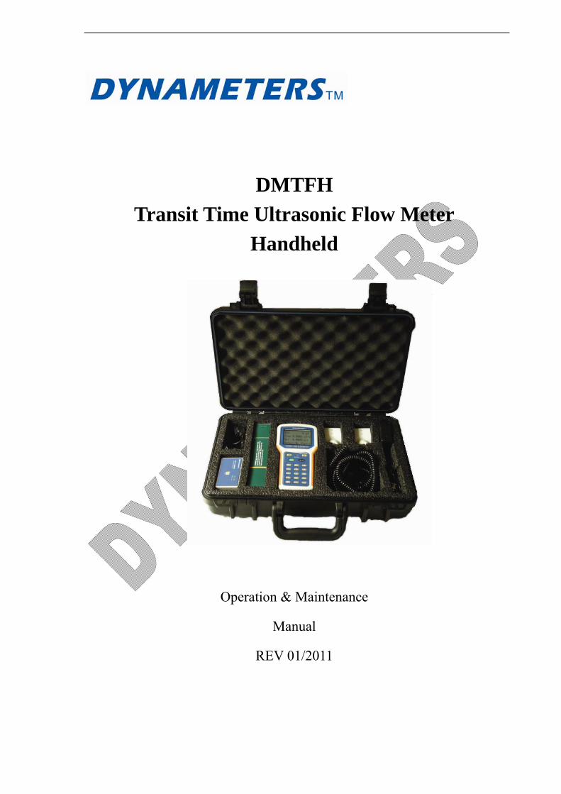
DMTFH
Transit Time Ultrasonic Flow Meter
Handheld
Operation & Maintenance
Manual
REV 01/2011

CONTENTS
PART-1 INTRODUCTION ................................................................................................................................ 1
1.1 GENERAL .................................................................................................................................................. 1
1.2 APPLICATION VERSATILITY............................................................................................................... 1
1.3 USER SAFETY........................................................................................................................................... 1
1.4 DATA INTEGRITY.................................................................................................................................... 1
1.5 USER FRIENDLY ...................................................................................................................................... 2
1.6 PRINCIPLE OF MEASUREMENT ......................................................................................................... 2
1.7 PARTS IDENTIFICATION....................................................................................................................... 3
1.8 PRODUCT IDENTIFICATION................................................................................................................ 5
1.9 SPECIFICATIONS .................................................................................................................................... 5
PART-2 START OPERATING INSTRUCTIONS............................................................................................ 6
2.1 POWER ON ................................................................................................................................................ 6
2.2 KEYPAD ..................................................................................................................................................... 6
2.3 MENU WINDOWS .................................................................................................................................... 7
2.4 MENU WINDOWS ARRANGEMENT .................................................................................................... 8
2.5 STEPS TO CONFIGURE THE PARAMETERS..................................................................................... 8
2.6 TRANSDUCERS MOUNTING LOCATING......................................................................................... 10
2.7 TRANSDUCERS MOUNTING............................................................................................................... 10
2.7.1 TRANSDUCERS SPACING................................................................................................................. 11
2.7.2 TRANSDUCER MOUNTING MODE................................................................................................. 12
2.8 INSTALLATION CHECKUP ................................................................................................................. 13
2.8.1 SIGNAL STRENGTH ........................................................................................................................... 13
2.8.2 SIGNAL QUALITY (M90) ................................................................................................................... 13
2.8.3 TOTAL TRANSIT TIME AND DELTA TIME.................................................................................... 14
2.8.4 TIME RATIO BETWEEN THE MEASURED TOTAL TRANSIT TIME AND THE
CALCULATED TIME (M91)........................................................................................................................ 14
PART-3 HOW TO USE MENU OPERATION............................................................................................... 15
3.1 HOW TO JUDGE WHETHER THE INSTRUMENT WORKS PROPERLY .................................... 15
3.2 HOW TO JUDGE THE LIQUID FLOWING DIRECTION................................................................. 15
3.3 HOW TO CHANGE THE UNITS SYSTEMS........................................................................................ 15
3.4 HOW TO SELECT A REQUIRED FLOW RATE UNIT ...................................................................... 15
3.5 HOW TO USE THE TOTALIZER MULTIPLIER................................................................................ 15
3.6 HOW TO OPEN OR SHUT THE TOTALIZERS .................................................................................. 15
3.7 HOW TO RESET THE TOTALIZERS .................................................................................................. 15
3.8 HOW TO RESET THE DEFAULT SETUPS.......................................................................................... 16
3.9 HOW TO USE THE DAMPING ............................................................................................................. 16
3.10 HOW TO USE THE ZERO-CUTOFF FUNCTION ............................................................................ 16
3.11 HOW TO SETUP A ZERO POINT........................................................................................................ 16
3.12 HOW TO GET A SCALE FACTOR FOR CALIBRATION................................................................ 17
3.13 HOW TO USE THE OPERATION LOCKER ..................................................................................... 17
3.14 HOW TO USE THE BUILT-IN DATA MEMORY............................................................................... 17
3.15 HOW TO USE THE FREQUENCY OUTPUT..................................................................................... 17
3.16 HOW TO USE THE TOTALIZER PULSE OUTPUT ......................................................................... 18
3.17 HOW TO PRODUCE AN ALARM SIGNAL ....................................................................................... 20
3.18 HOW TO USE THE BUILT-IN BUZZER ............................................................................................ 20
3.19 HOW TO MODIFY THE BUILT-IN CALENDAR.............................................................................. 20
3.20 HOW TO ADJUST THE LCD CONTRAST ........................................................................................ 20
3.21 HOW TO USE THE RS232 SERIAL INTERFACE............................................................................. 20
3.22 HOW TO VIEW THE DATE TOTALIZERS ....................................................................................... 20
3.23 HOW TO USE THE WORKING TIMER ............................................................................................ 21
3.24 HOW TO USE THE MANUAL TOTALIZER ..................................................................................... 21
3.25 HOW TO CHECK THE ESN AND OTHERS...................................................................................... 21
3.26 HOW TO KNOW HOW LONG THE BATTERY WILL LAST AND HOW TO CHARGE THE
BUILT-IN BATTERY..................................................................................................................................... 21
PART-4 MENU WINDOW DETAILS............................................................................................................. 22
PART-5 TROUBLESHOOTING ..................................................................................................................... 28
5.1 POWER-ON ERROR DISPLAYS AND COUNTER-MEASURES ..................................................... 28
5.2 ERROR CODE AND COUNTER-MEASURES .................................................................................... 28
5.3 OTHER PROBLEMS AND SOLUTIONS ............................................................................................. 30
5.4 USE MENU WINDOWS FOR TRANSDUCER MOUNTING INSPECTION.................................... 30
PART-6 COMMUNICATION PROTOCOL .................................................................................................. 32
6. 1 GENERAL ............................................................................................................................................... 32
6.2 INTERFACE PIN-OUT DEFINITION .................................................................................................. 32
6.3 THE PROTOCOL .................................................................................................................................... 32
6.4 PROTOCOL PREFIX USAGE ............................................................................................................... 33
6.5 CODES FOR THE KEYPAD................................................................................................................... 34
PART-7 WARRANTY AND SERVICE ........................................................................................................... 36
7.1 WARRANTY ............................................................................................................................................ 36
7.2 SERVICE .................................................................................................................................................. 36
APPENDUM 1 FLUID CHARACTERISTIC (SOUND SPEED) TABLE.............................................. 37
1 FLUID PROPERITIES ................................................................................................................................. 37
2 WATER SOUND SPEED TABLE................................................................................................................. 39
APPENDUM 2 DATA LOGGER AND ANALYSE SOFTWARE USAGE ............................................. 40

DMTFH 1
PART-1 INTRODUCTION
1.1 GENERAL
Series DMTFH ultrasonic flow meters feature advanced Transit-Time measuring technology, providing accurate and reliable flow rate and total flow display, The DMTFH utilizes a non-invasive transducer which is hand-held or strapped to the outside of a pipe, which will provide benefits of non-fouling operation and ease of installation. DMTFH transit time flow meters utilize two transducers that function as both ultrasonic transmitters and receivers. The transducers are clamped on the outside of a closed pipe at a specific distance from each other. The transducers can be mounted in V-mode where the sound transverses the pipe two times, W-mode where the sound transverses the pipe four times, or in Z mode where the transducers are mounted on opposite sides of the pipe and the sound crosses the pipe once. This selection is based on pipe and liquid characteristics. The flow meter operates by alternately transmitting and receiving a frequency modulated burst of sound energy between the two transducers and measuring the time interval that it takes for sound to travel between the two transducers. The difference in the time interval measured is directly related to the velocity of the liquid in the pipe.
1.2 APPLICATION VERSATILITY
The DMTFH flow meter can be successfully applied on a wide range of metering applications. The simple to program transmitter allows the standard product to be used on pipe sizes ranging from 0.8 - 100 inch [20 mm - 2500 mm] internal diameters. A variety of liquid applications can be accommodated: ultra-pure liquids, potable water, chemicals, raw sewage, reclaimed water, cooling water, river water, plant effluent, etc. Because the transducers are non-contacting and have no moving parts, the flow meter is not affected by system pressure, fouling or wear. Standard transducers are rated to 250°F [121°C].
1.3 USER SAFETY
The DMTFH employs modular construction and provides electrical safety for the operator. The display face contains voltages no greater than 5Vdc. All user connections are made through sealed bulk-head plugs located on the side of the DMTFH enclosure.
1.4 DATA INTEGRITY
Non-volatile flash memory retains all user-entered configuration values in memory for several years, even if power is lost or the unit is turned off. Data Logger values are stored in flash memory in the logger. Password protection is provided as part of the Security menu and prevents inadvertent configuration changes or totalizer resets. A time-keeper is integrated in the flow meter for the index of date totalizing and works as the time base of flow accumulation. It keeps operating as long as the battery’s terminal voltage is over 1.5V. In case of battery failure, the time-keeper will not keep running and it will lose proper time values. The user must re-enter proper time values in case the battery becomes totally exhausted. An improper time value affects no other functions but the date totalizer.
DMTFH 2
1.5 USER FRIENDLY
The DMTFH features the ease of operation, high accuracy and outstanding reliability, while the software provides a very user friendly interface and much more functions. It employs a patent balanced lower voltage multi-pulse igniting circuit which increases the anti-interference ability magnificently so that the flow meter will work properly even in demanding industrial environments such as those with power frequency transmitter working nearby. The signal receiving circuits feature self-adapting performance so as to ensure that the user can easily operate the instrument without any adjustment. The built-in rechargeable Ni-H battery can work continuously for more than 12 hours without recharge.
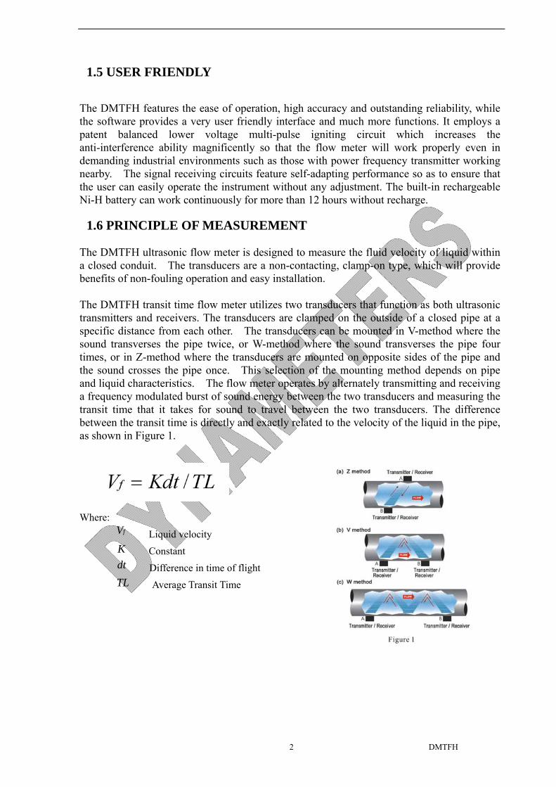
1.6 PRINCIPLE OF MEASUREMENT
The DMTFH ultrasonic flow meter is designed to measure the fluid velocity of liquid within a closed conduit. The transducers are a non-contacting, clamp-on type, which will provide benefits of non-fouling operation and easy installation.
The DMTFH transit time flow meter utilizes two transducers that function as both ultrasonic transmitters and receivers. The transducers are clamped on the outside of a closed pipe at a specific distance from each other. The transducers can be mounted in V-method where the sound transverses the pipe twice, or W-method where the sound transverses the pipe four times, or in Z-method where the transducers are mounted on opposite sides of the pipe and the sound crosses the pipe once. This selection of the mounting method depends on pipe and liquid characteristics. The flow meter operates by alternately transmitting and receiving a frequency modulated burst of sound energy between the two transducers and measuring the transit time that it takes for sound to travel between the two transducers. The difference between the transit time is directly and exactly related to the velocity of the liquid in the pipe, as shown in Figure 1.
Where:
fV Liquid velocity
K Constant dt Difference in time of flight
TL Average Transit Time
DMTFH 3
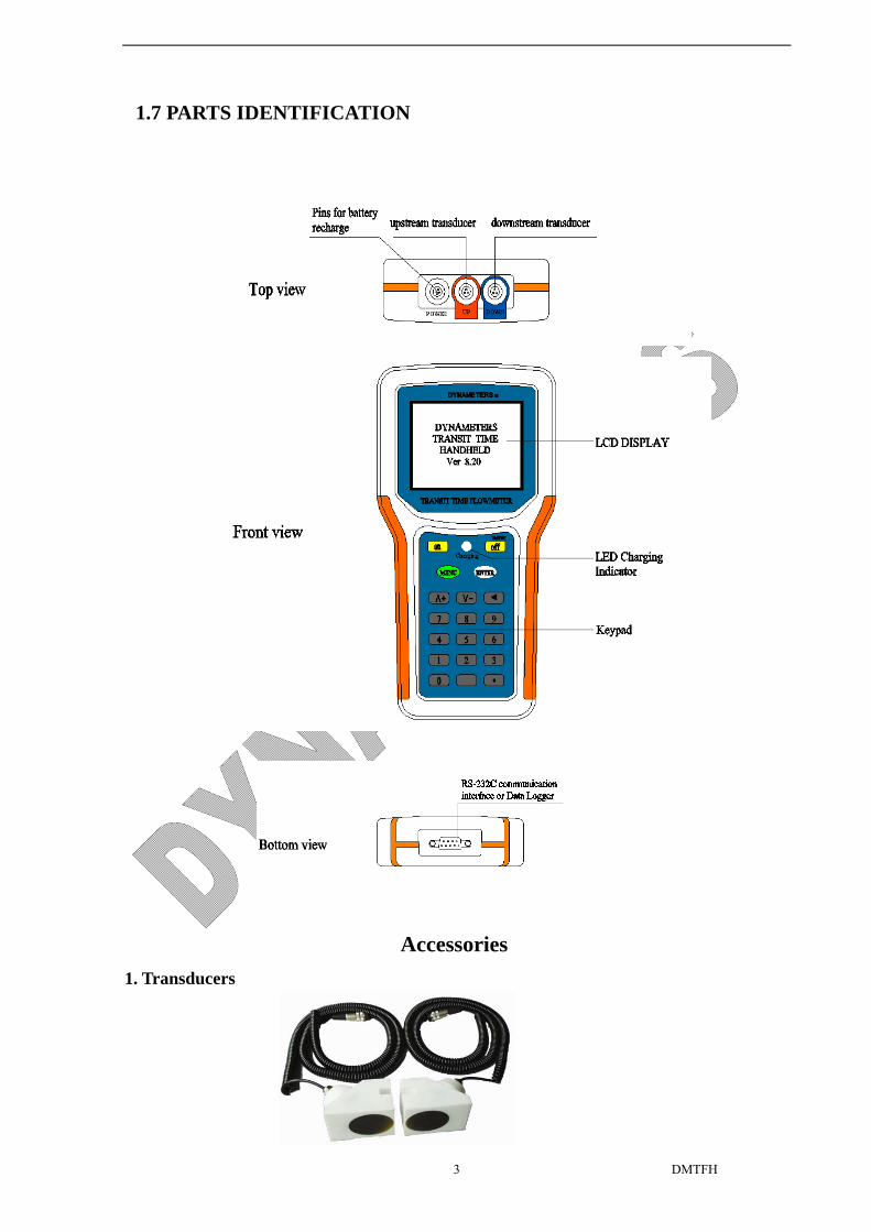
1.7 PARTS IDENTIFICATION
Accessories
1. Transducers
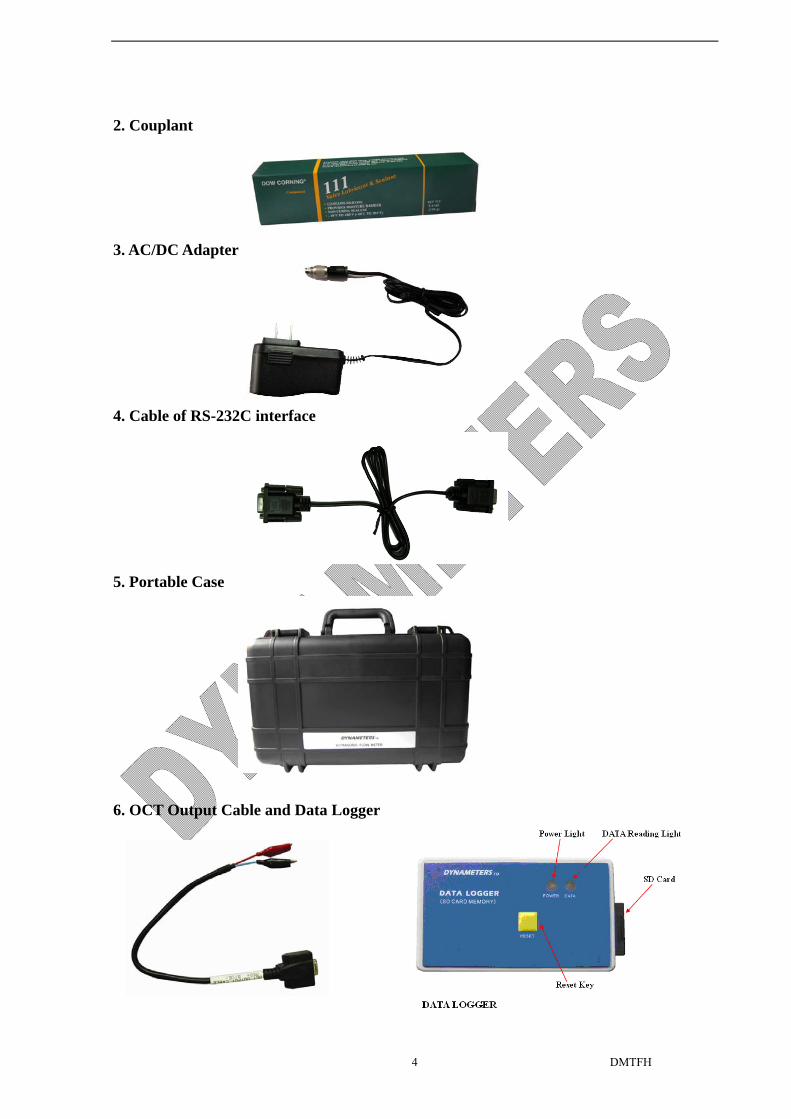
DMTFH 4
2. Couplant
3. AC/DC Adapter
4. Cable of RS-232C interface
5. Portable Case
6. OCT Output Cable and Data Logger
DMTFH 5
1.8 PRODUCT IDENTIFICATION
Each set of the DMTFH Series flow meter has a unique product identification or ESN written into the software that can only be modified with a special tool by the manufacturer. In case of any hardware failure, please provide this number which is located on menu window number M61 when contacting the manufacture.
1.9 SPECIFICATIONS
Transmitter Specifications Principle of Measurement Principle of Transit Time, DSP technology and MultiPulseTM
Transducer Technology
Repeatability 0.2%
Accuracy ±1.0 ∽ 2.0 % of reading at rates >0.5 m/s); ±0.005 m/s of reading at rates<0.5 m/s
Response Time 0-999 seconds, user-configurable Velocity ±12 m/s Pipe Size DN15-DN4500 (mm)
Rate Units Meter, Feet, Cubic Meter, Liter, Cubic Feet, Gallon, Imperial Gallon, Oil Barrel, Liquid Barrel, Imperial Liquid Barrel, Million Gallons. User configurable.
Totalizer 7-digit totals for net, positive and negative flow respectively Security Setup values Modification Lockout. Access code needs unlocking Display 4x16 English letters Communication Interface RS-232C, baud-rate: from 75 to 57600. Transducers Model M1 for standard, other 3 models for optional Transducer Cable Length Flexible Cable, standard 4 meters, optional 8 meters
Power Supply 3 AAA Ni-H built-in batteries. When fully recharged it will last over 12 hours of operation. 100V-240VAC for the charger
Data Logger Options: SD card data (up to 8GB based SD card capacity) logger and software, can connect to PC run windows, read and edit data table. User can select memory interval freely as needed.
Manual Totalizer 7-digit press-key-to-go totalizer for calibration Housing Material ABS Case Size 203x101x34mm Handset Weight 550g (1.2 lbs) with batteries
Transducer Specifications
Liquid types Virtually most any liquid containing less than 2% total suspended solids (TSS) or aeration.
Liquid temperature -40 to 240F [-40 to 121 ]; (opt) ℃ -40 to 480F [-40 to 250 ]℃
Transducer Cable Length Flexible cable, standard 4 meters, (opt) 8 meters
Pipe size Std M type transducer: 40 to 1000 mm] pipe I.D, Options: L transducer: 1000- 4500 mm, S transducer: 15-50mm
Pipe material All kind of steel and cast iron, PVC etc.

DMTFH 6
PART-2 START OPERATING INSTRUCTIONS
2.1 POWER ON
Press the ON key to switch on the instrument and press the OFF to turn off the power.
Once the flow meter is switched on, it will run a self diagnostic program, checking first the hardware and then the software integrity. If there is any abnormality, corresponding error messages will display.
Generally, there should be no display of error messages, and the flow meter will go to the most commonly used Menu Window Number 01 (short for M01) to display the Velocity, Flow Rate, Positive Totalizer, Signal Strength and Signal Quality, based on the pipe parameters configured last time by the user or by the initial program.
The flow measurement program always operates in the background of the user interface. This means the flow measurement will keep on running regardless of any user menu window browsing or viewing. Only when the user enters new pipe parameters will the flow meter change measurement to the new parameter changes.
When new pipe parameters have been entered or when the power has been just switched on, the flow meter will enter an adjusting mode to make the signals magnified with proper amplification. By this step, the flow meter is going to find the best threshold of receiving signal. The user will see the progress by the number 1, 2, or 3, which are indicated on the right lower corner of the LCD display.
When the transducers have been adjusted on the pipe by the user, the flow meter will re-adjust the signal automatically.
Any user-entered configuration value will be retained into the NVRAM of the flow meter, until it is modified by the user.
2.2 KEYPAD
The keypad for the operation of the flow meter has 16+2 keys, as shown by the right via Keys 0 ~ 9 and . are keys to enter numbers, Key ∧/+ is the going UP key, when the user wants to go to the upper menu window. It also works as + key when entering numbers
Key ∨/- is the going DOWN key, when the user wants
to go down-sided menu window. It also works as the
‘–‘ key when entering numbers.
Key ◄ is backspace key, when the user wants
go left or wants backspace the left character that

DMTFH 7
is located to the left of the cursor.
Key ENTER is the ENTER key for any inputting or selections.
Key MENU is the key for the direct menu window jump over. Whenever the user wants to proceed to a certain menu window, the user can press this key followed by 2-digit numbers.
The MENU key is shortened as the ‘M’ key afterward when referring to the menu windows.
The ON key is for the power on.
The OFF key is for the power off.
2.3 MENU WINDOWS
The user interface of this flow meter comprises about 100 different menu windows that are numbered by M00, M01, M02 … M94 etc.
There are 2 methods to enter certain menu window:
(1) Direct going/entering. The user can press the MENU key followed by two-digit number keys. For example, the menu window M20 is for the entering of Fluid Type. The display will go to the M20 menu window after the user presses MENU 2 0 .
(2) Pressing ∧/+ and ∨/- keys. Each time of the ∧/+ key pressing will proceed to the lower-numbered menu window. For example, if the current window is on M12, the display will go to the number M11 window after pressing the ∧/+ key or M13 after pressing the ∨/- key.
There are three different types of menu windows:
(1) Menu windows for number entering, like M11 for the entering of pipe outer diameter.
(2) Menu windows for option selection/selecting options, like M14 for the selection of pipe materials.
(3) Displaying windows only, like M00 to display Velocity, Flow Rate etc.
For number entering windows, the user can directly press the starting digit key when the user is going to modify the value. For example, when the current window is on M11, and the user is going to enter 154.6 as the pipe outer diameter, the user can get the numbers entered by pressing the following serial keys: 1 5 4 . 6 ENTER.
For the option selection windows, the user should first press the ENTER key to a selection modification mode and then select the relevant options by pressing the ∧/+ and ∨/- keys or the digit keys to select the option with a number antecedent to the option. In the end, the ENTER key must be pressed to make the selection. For example, with menu window M14 for the selection of pipe material selection, (the MENU 1 4 should be pressed first to enter this menu window if the current menu window is on a different window. The pipe material is stainless steel which has a number “1” antecedent to “stainless steel” on the

DMTFH 8
display, the user should first press the ENTER key to enter into a selection modification mode, then either make the selection by pressing the ∧/+ and ∨/- keys to make the cursor on the line that displays “1. Stainless Steel”, or make the selection by pressing the 1 key directly.
Generally, the ENTER key must be pressed to enter a modification mode. If the “Locked M47 Open’ message is indicated on the lowest line of the LCD display, it means the modification operations is locked out. In such cases, the user should go to M47 to have the instrument unlocked first before any further modification can be made.
2.4 MENU WINDOWS ARRANGEMENT
M00~M09 windows for the display of the flow rate, velocity, date time, totalizers, battery voltage and estimated working hours for the battery.
M10~M29 windows for entering the pipe parameter.
M30~M38 windows for flow rate unit selections and totalizer unit selections.
M40~M49 windows for response time, zeroing, calibration and modification password setup.
M50~M53 windows for the built-in logger
M60-M78 windows for time-keeper initialization, version and ESN information viewing and alarms.
M82 window for viewing date totalizer.
M90~M94 are diagnostic windows for a more accurate measurement.
M+0~M+8 are windows for some additional functions, including a scientific calculator, viewer on records such as total working hours, turn-on and turn-off times, dates and times when the flow meter has been turned on or turned off.
Other menu windows such as M88 have no functions, or functions were cancelled because they are not applied to this version of the software.
The major reason why the menu windows are arranged in this way is that the software programmer hopes that the menu window arrangement for this version has the most compatibility with the previous versions of the DMTFH dedicated model software. This will make it easier for the former version users with this flow meter series.
2.5 STEPS TO CONFIGURE THE PARAMETERS
The following parameters need to be configured for a proper measurement:
(1) Pipe outer diameter (O.D.) (2) Pipe wall thickness (3) Pipe materials (for non-standard pipe materials*, the sound speed for the material must be
configured too)
DMTFH 9
*Standard pipe materials and standard liquids refer to those with the sound parameters that have already been programmed into software of the flow meter; therefore there is no need to configure them.
(4) Liner material and its sound speed and thickness, if there is any liner. (5) Liquid type (for non-standard liquids, the sound speed of the liquid is also needed) (6) Transducer type adapted to the flow meter. Generally the Standard M1 or the Frame
M-sized transducers will be the selected option. (7) Transducer mounting methods (the V-method or Z-method is the common option) (8) Check up the Space displayed on M25 and install the transducers accordingly.
For standard pipe materials and standard liquids, the following detailed step-by-step setup is recommended.
(1) Press keys MENU 1 1 to enter M11 window to input the digits for the pipe outer diameter, and then press ENTER key.
(2) Press key ∨/- to enter M12 window to input the digits for the wall thickness and then press ENTER key.
(3) Press key ∨/- to enter M14 window, and press ENTER key to enter the pipe material. Use keys ∧/+ and ∨/- to scroll up and down to the intended pipe material, and then press ENTER key. If you select “Other”, you must enter Menu15, pipe sound speed.
(4) Press key ∨/- to enter M16 window, press ENTER key to enter the option selection mode, use keys ∧/+ and ∨/- to scroll up and down to the liner material, and then press ENTER key. Select “No Liner”, if there is no liner, If you select “Other”, you must enter Menu17, liner sound speed.
(5) Enter “Liner Thickness” in Menu18.
(5) Press key ∨/- to enter M20 window, press ENTER key to enter Fluid Type, use keys ∧/+ and ∨/- to scroll up and down to the proper liquid, and then press ENTER key. If you select “Other”, you must enter Menu21, Fluid sound speed and Menu 22, Fluid Viscosity
(6) Press key ∨/- to enter M23 window, press ENTER key to enter the Transducer Type, use keys ∧/+ and ∨/- to scroll up and down to the proper Transducer Type (Standard S, M, L) you selected, and then press ENTER key. Plug Type C and B are for Insertion transducer, no matter with Clamp-on transducers.
(7) Press key ∨/- to enter M24 window to select Transducer Mounting mode, and then press ENTER key. Refer to 2.7.2 Transducer Mounting Mode for detail.
(8) When above steps finished, Menu 25 will display transducer install spacing. Refer to 2.7.1 for detail.
(9) Enter Menu 90 and 91, to adjust the transducer spacing for good run status. Try to
move one transducer, let this value closer to 100.0%. Meter display will be more

DMTFH 10
accurate. Please read Part 4, Menu Windows details, it will help you have a good operation.
The first-time users may need some time to get familiar with the operation. However, the user friendly interface of the instrument makes the operation quite easy and simple. Before long, the user will configure the instrument with very little key pressing, since the interface allows the user to go to the desired operation directly without any extra steps.
The following tip will facilitate the operation of this instrument.
(1) When the window display is between M00 to M09, press MENU key, then press a number key x , the user will go directly to the M0x window. For example, if the current window displays M01, press 7 and the user will go to M07.
(2) When the window display is under M00 to M09, press the ENTER key and the user will go to Menu90; Menu 90 display the meter run status, press ENTER key to return. Press the dot key to go to M11
2.6 TRANSDUCERS MOUNTING LOCATING
The first step in the installation process is the selection of an optimum location in order to obtain a more accurate measurement. For this to be completed effectively, a basic knowledge about the pipe straight running would be advisable. An optimum location would be defined as a straight pipe length full of liquid that is to be measured. The piping can be in vertical or horizontal position. The following table shows examples of optimum locations.
Principles to selection of an optimum location
(1) Install the transducers on a longer length of the straight pipe. The longer the better, and make sure that the pipe is completely full of liquid.
(2) Make sure that the temperature on the location does not exceed the range for the transducers. Generally speaking, the closer to the room temperature, the better.
(3) Take the pipe fouling into consideration. Select a straight length of a relatively newer pipe. If the condition is not satisfying, consider the fouling thickness as part of the liner for a better result.
(4) Some pipes have a kind of plastic liner, and between the outer pipe and the liner there may be a certain thickness difference that will prevent the ultrasonic waves from direct traveling. Such conditions will make the measurement very difficult. Whenever possible, try to avoid this kind of pipes. If impossible, try our plug-in transducers that are installed permanently on the pipe by drilling holes on the pipe while liquid is running inside.
2.7 TRANSDUCERS MOUNTING
The transducers used by the DMTFH series ultrasonic flow meter are made of piezoelectric crystals both for transmitting and receiving ultrasonic signals through the wall of liquid piping system. The measurement is realized by measuring the traveling time difference of the ultrasonic signals. Since the difference is very small, the spacing and the alignment of the transducers are critical factors to the accuracy of the measurement and the performance of the system. Meticulous care should be taken for the installation of the transducers.
DMTFH 11
Steps to the installation of the transducers
(1) Locate an optimum position where the straight pipe length is sufficient, and where pipes are in a favorable condition, e.g., newer pipes with no rust and ease of operation.
(2) Clean any dust and rust. For a better result, polishing the pipe with a sander is strongly recommended.
(3) Apply adequate coupler to the spot where the transducers are to be installed and leave no gap between the pipe surface and the transducers.
Take care to avoid any sand or dust particles left between the pipe outer surface and the transducers.
To avoid gas bubbles inside the upper part of the pipe, the transducers should be installed horizontally by the side of the pipe.
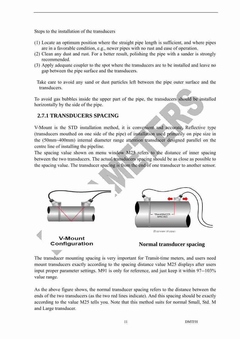
2.7.1 TRANSDUCERS SPACING
V-Mount is the STD installation method, it is convenient and accurate, Reflective type (transducers mouthed on one side of the pipe) of installation used primarily on pipe size in the (50mm~400mm) internal diameter range attention transducer designed parallel on the centre line of installing the pipeline. The spacing value shown on menu window M25 refers to the distance of inner spacing between the two transducers. The actual transducers spacing should be as close as possible to the spacing value. The transducer spacing is from the end of one transducer to another sensor.
The transducer mounting spacing is very important for Transit-time meters, and users need mount transducers exactly according to the spacing distance value M25 displays after users input proper parameter settings. M91 is only for reference, and just keep it within 97--103% value range. As the above figure shows, the normal transducer spacing refers to the distance between the ends of the two transducers (as the two red lines indicate). And this spacing should be exactly according to the value M25 tells you. Note that this method suits for normal Small, Std. M and Large transducer.
Normal transducer spacing

DMTFH 12
For Magnetic transducers, the definition of transducer spacing is the distance between the two scale lines, just as showed bellow:
The value displayed in M25 for magnetic transducer spacing refers to the distance showed in the above figure. (Note: The displayed value in M25 is larger than the distance between the ends of the two magnetic transducers.) Users should mount the magnetic transducers with the above showed spacing exactly according to the M25 value.
2.7.2 TRANSDUCER MOUNTING MODE
V-Mount is the most widely used mode for daily measurement with pipe inner diameters ranging from 20 millimeter to 300 millimeter. It is also called standard mode or method. But if the meter displays error code or low signal strength and bad signal quality, for instance, some old pipe etc., user should select Z-Mount.
Z-Mount is commonly used when the pipe diameter is between 300 millimeters and 4500 mm.

DMTFH 13
W-Mount is usually used on plastic pipes with a diameter from 10 mm to 50 mm.
2.8 INSTALLATION CHECKUP
Through the checkup of the installation, one can: check the receiving signal strength, the signal quality Q value, the traveling time difference of the signals, the estimated liquid speed, the measured traveling time of the signals and the calculated traveling time ratio. Therefore, optimum measurement result and longer running time of the instrument can be achieved.
2.8.1 SIGNAL STRENGTH
Signal strength indicates the amplitude of receiving ultrasonic signals by a 3-digit number. [00.0] means there is no signal detected and [99.9] refers to the maximum signal strength that can be received.
Although the instrument works well if the signal strength ranges from 50.0 to 99.9, stronger signal strength should be pursued, because a stronger signal means a better result. The following methods are recommended to obtain stronger signals:
(1) Relocate a more favorable location, if the current location is not good enough for a stable and reliable flow reading, or if the signal strength is lower than 700.
(2) Try to polish the outer surface of the pipe, and apply more coupler to increase the signal strength.
(3) Adjust the transducers both vertically and horizontally while checking the varying signal strength, stop at the highest position, and then check the transducers spacing to make sure the transducers spacing is the same as what the M25 shows.
2.8.2 SIGNAL QUALITY (M90)
Signal quality is indicated as the Q value in the instrument. A higher Q value would mean a higher Signal and Noise Ratio (short for SNR), and accordingly a higher degree of accuracy would be achieved. Under normal pipe condition, the Q value is in the range 60-99, the higher the better.
Causes for a lower Q value could be:
(1) Interference of other instruments and devices such as a powerful converter working nearby. Try to relocate the flow meter to a new place where the interference can be reduced.

DMTFH 14
(2) Bad sonic coupling for the transducers with the pipe. Try to apply more coupler or clean the surface, etc.
(3) Pipes are difficult to be measured. Relocation is recommended.
2.8.3 TOTAL TRANSIT TIME AND DELTA TIME
The numbers displayed on menu window M93 are called total transit time and delta time respectively. They are the primitive data for the instrument to calculate the flow rate inside the pipe. So the flow rate indication will vary accordingly with the total time and delta time.
The total transit time should remain stable or vary little.
If the delta time fluctuates higher than 20%, it means there are certain kinds of problems with the transducer installation.
2.8.4 TIME RATIO BETWEEN THE MEASURED TOTAL TRANSIT TIME AND THE CALCULATED TIME (M91)
This ratio would be used to check the transducer installation. If the pipe parameters are entered correctly and the transducers are installed properly, the value for this ratio (M91) should be in the range of 100±3. If this range is exceeded, the user should check:
(1) If the pipe parameters are correctly entered. (2) If the actual spacing of the transducers is right and the same as what the window M25
shows. (3) If the transducers are installed properly in the right directions. (4) If the mounting location is good and if the pipe has changed shape or if there is too much
fouling inside the pipes (5) Other poor conditions
15
PART-3 HOW TO USE MENU OPERATION
3.1 HOW TO JUDGE WHETHER THE INSTRUMENT WORKS PROPERLY
Generally speaking, when ‘R’ is displayed in the lowest right corner of LCD display, the instrument is working properly.
If an ‘H’ flashes on that place, there could be poor signal received. Please refer to the chapters on diagnosis.
If an ‘I’ is displayed, it means that there is no signal detected.
If a ‘J’ is displayed, it means that the hardware of this instrument could be out of order. Refer to the chapter on diagnosis.
3.2 HOW TO JUDGE THE LIQUID FLOWING DIRECTION
(1) Make sure that the instrument works properly (2) Check the flow rate for the indication. If the displayed value is POSITIVE, the direction
of the flow will be from the RED transducers to the BLUE transducers; if the displayed value is NEGATIVE, the direction will be from the BLUE transducers to the RED transducers.
3.3 HOW TO CHANGE THE UNITS SYSTEMS
Use menu window M30 for the selection of unit system in English or Metric system. 3.4 HOW TO SELECT A REQUIRED FLOW RATE UNIT
Use menu window M31 to select the flow unit first and then the timing unit.
3.5 HOW TO USE THE TOTALIZER MULTIPLIER
Use window M33 to select a proper totalizer. Make sure that the totalizer pulse is appropriately speeded. It should not be too fast and neither too slow. A speed of producing a pulse in several seconds or minutes is preferable.
If the totalizer multiplier is too small, there can be a loss of accumulation pulse because the output device can output only one pulse in a measurement period (500milliseconds)
If the totalizer multiplier is too large, the output pulse will be too fewer for the devices that are connected with the instrument for a quicker response.
3.6 HOW TO OPEN OR SHUT THE TOTALIZERS
Use M34, M35 and M36 to turn on or turn off the NET, POS, or NEG totalizer respectively.
3.7 HOW TO RESET THE TOTALIZERS
Use M37 to reset the proper totalizer.
16
3.8 HOW TO RESET THE DEFAULT SETUPS
Use M37, when the ‘selection’ message is displayed. Press the dot key first and the message ‘Master Erase’ will display, then press the backspace key ◄
The master erase step will erase all the parameters entered by the user and setup the instrument with default values.
3.9 HOW TO USE THE DAMPING
The damping acts as a filter for a stable reading. If ‘0’ is entered in window M40, that means there is no damping. A bigger number brings a more stable effect. But bigger damping numbers will prevent the instrument from acting quickly.
Numbers 0 to 10 are commonly used for the damping value.
3.10 HOW TO USE THE ZERO-CUTOFF FUNCTION
The number displayed in window M41 is called the low-cutoff value. The flow meter will replace these flow rate values that are absolutely less than the low-cutoff value with ‘0’. This means the flow meter will avoid any invalid accumulation when the actual flow is below the zero-cutoff value.
The low-cutoff value does not affect the flow measurement when the actual flow is absolutely greater than the low-cutoff value.
3.11 HOW TO SETUP A ZERO POINT
It is necessary to establish the true zero flow condition and program that set point into the
instrument. If the zero set point is not at true zero flow, a measurement difference may occur.
Because every flow meter installation is slightly different and sound waves can travel in
slightly different ways through these various installations, a provision is made in this entry to
establish “ True Zero” flow – SETUP ZERO.
There exists a ‘Zero Point’ with certain installation which means the flow meter will
display a non-zero value when the flow is absolutely stopped. In this case, setting a
zero point with the function in window M42 will bring a more accurate measurement
result. When do a calibration test, it is also very important.
Make sure that the pipe is full of liquid and the flow is absolutely stopped - securely close
any valves and allow time for any settling to occur. Then run the function in window M42
by press the MENU 4 2 keys, then press ENTER key and wait until the counter
readings displayed in the lower right corner of the screen goes to “00”; thus, the zero set is
completed and the instrument indicates the results automatically through Window No.01.
Repeat zero set calibration if it still needs to be minimized, i.e. the velocity reading is still
high.

17
3.12 HOW TO GET A SCALE FACTOR FOR CALIBRATION
The scale factor is the ratio between the ‘actual flow rate’ and the indicated value by the flow meter.
The scale factor can be determined by calibration with flow calibration equipment.
3.13 HOW TO USE THE OPERATION LOCKER
The system locker provides a means of preventing inadvertent configuration changes or totalizer resets.
When the system is locked, menu window browsing can be done without affecting any change, but any modifications are prohibited.
The system can be locked without a password or with a one 1 to 4 digit password. With a no-password locking, directly press the ENT key when the password input prompt displays.
If the password is forgotten, please contact the factory.
3.14 HOW TO USE THE BUILT-IN DATA MEMORY
The data memory has a space of 24K bytes of memory, which will hold about 2000 lines of data.
Use M50 to turn on the data memory and for the selection for the items that is going to be logged.
Use M51 for the times when the logging begins and at how long an interval sustains and how long the data logging will last.
Use M52 for the direction of logging data. The default setting will permit the logging data to be stored in the data memory buffer.
Logging data can be redirected to the RS-232C interface without being stored into the data memory buffer. Dumping the logging data through the RS-232C interface and the clearing of the buffer can be operated with a function in window M52.
Use M53 to view the data in the data memory buffer.
3.15 HOW TO USE THE FREQUENCY OUTPUT
Only For Flow Rate Output.
There is a Frequency Output in all series DMTF flow meters. This frequency output signal, which represents the flow rate, is intended to connect with other instruments.
The Frequency Output is totally user-configurable. Generally, four parameters should be configured for the setups.

18
Enter the lower flow rate value in window M68 and the higher flow rate value in window M69.
Enter the frequency range in window M67.
For example, assume that the flow rate varies in a range 0m3/h to 2000m3/h, and an output signal is at a maximum frequency of 1000Hz, the minimum of 200Hz is going to be required for other instrumentation. The user should enter 0 in M68 and 2000 in M69, and enter 200 and 1000 in window M67.
Please note that the user has to make the selection with OCT (Open Collect Transistor) output setups in window M78 by selecting the 13th option reading like ‘FO output’ to direct the frequency output to the OCT OUTPUT hardware device.
The OCT output shares pins with the RS-232C interface, and the terminal is at Pin 1 for OCT + and the ground is at Pin 5.
3.16 HOW TO USE THE TOTALIZER PULSE OUTPUT
Relay “+, -”. Only For Totalizer Output or Relay Alarm Output.
The totalizer output will produce a pulse output with every unit flow of the totalizer.
Refer §3.4 and §3.5 for the setups of the totalizer units and multiplier.
The terminal wiring diagram is the same with above 3.15.
The totalizer pulse output can only be realized by mapping the pulse output to the OCT or

19
BUZZER hardware devices.
For example, assume that the POS totalizer pulse output is needed, and every pulse should represent 0.1cubic meter of liquid flow; the pulse output will be mapped to the internal Buzzer, so that with every 0.1 cubic meter of flow the BUZZER will beep for a while.
The following setups should be taken:
(1) Select the unit Cubic Meter under window M32. (2) Select the Multiplier as ‘2. X0.1’ under window M33. (3) Select the output option ‘9. POS INT Pulse’ under window M77. (INT stands for
totalized )
The OCT output shares pins with the RS-232C interface, and the terminal is at Pin 6 and the ground is at Pin 6.
Note: Once the transmitter is powered on, the “RELAY -, +” output is normally closed state. The transmitter power supply interruption alarm output is automatically output alarm, if the transmitter is powered off, the “RELAY -, +” will automatically change normally closed state into normally open state. When user needs Relay Output, the wiring diagram is shown as Fig 3.1. it configures the relay to output a 50 mSec pulse each time the minimum display totalizer increments.
Fig 3.1 Relay Wiring Diagram

20
3.17 HOW TO PRODUCE AN ALARM SIGNAL
There are 2 types of hardware alarm signals that are available with this instrument. One is the Buzzer, and the other is the OCT output.
Both for the Buzzer and OCT output the triggering sources of the event include the following:
(1) Alarms on when there is no receiving signal (2) Alarms on when there is poor signal received. (3) Alarms on when the flow meter is not in normal measurement modes. (4) Alarms on reverse flow. (5) Alarms on the overflow of the Frequency Output (6) Alarms on when the flow is out of a designated range set by the user.
There are two out-of-normal-range alarms in this instrument. They are called #1 Alarm and #2 Alarm. The flow range can be user-configurable through M73, M74, M75, M76.
For example, assume that the Buzzer should start beeping when the flow rate is less than 300 m3/h and greater than 2000m3/h, the following steps for setups would be recommended.
(1) Enter 300 under M73 for #1 alarm low flow rate (2) Enter 2000 under M74 for #1 alarm high flow rate (3) Select the item reading like ‘6. Alarm #1’ under M77.
3.18 HOW TO USE THE BUILT-IN BUZZER
The built-in buzzer is user-configurable. It can be used as an alarm. Use M77 for setups.
3.19 HOW TO MODIFY THE BUILT-IN CALENDAR
No modification on the built-in calendar will be needed in most cases. The calendar runs on insignificant amount of power supply. Modification will be required only in such cases as when the battery is totally consumed, or when the changing of the battery takes a long time.
Press the ENT key under M61 for Modification. Use the dot key to skip over these digits that need no modification.
3.20 HOW TO ADJUST THE LCD CONTRAST
Use M70 to the LCD contrast. The adjusted result will be stored in the EEPROM so that the MASTER ERASE will make no effect on the contrast.
3.21 HOW TO USE THE RS232 SERIAL INTERFACE
Use M62 for the setup of the RS-232C serial interface.
3.22 HOW TO VIEW THE DATE TOTALIZERS
Use M82 to view the date totalizers that are comprised of a daily totalizer, a monthly totalizer and a yearly totalizer.
21
3.23 HOW TO USE THE WORKING TIMER
Use the working timer to check the time that has passed with a certain kind of operation. For example, use it as a timer to show how long a fully-charged battery will last.
Under M72, press ENT key and then select YES to reset the timer.
3.24 HOW TO USE THE MANUAL TOTALIZER
Use M28 for the manual totalizer. Press ENT key to start and stop the totalizer.
3.25 HOW TO CHECK THE ESN AND OTHERS
Every set of the DMTFH series flow meter utilizes a unique ESN to identify the meter. The ESN is an 8-digit number that provides the information of version and manufacturing date. The user can also employ the ESN for instrumentation management. The ESN is displayed in window M61.
Other details about the instrument are the total working hours displayed in window M+1, and the total power-on times displayed in window M+4.
3.26 HOW TO KNOW HOW LONG THE BATTERY WILL LAST AND HOW TO CHARGE THE BUILT-IN BATTERY
Use M07 to check how long the battery will last. The instrument can operate either from the built-in Ni-H rechargeable battery, which will last over 10 hours of continuous operation when fully recharged, or from an external AC/power supply from the battery charger.
The battery charging circuits employ a scheme of constant-current and constant-voltage. It has a characteristic of fast charging at the beginning and very slow charging when the battery approaches to full recharge. Generally, when the green LED starts coming on, the battery would be nearly 95% recharged and when the red LED is off, the battery would be 98% recharged.
Since the charging current becomes tapered when the battery recharge is nearly completed, i.e. the charging current becomes smaller and smaller, therefore, there should be no over-recharging problem. That means the charging progress can last very long. The charger can be connected to the handset all the time when an around-the-clock measurement is required.
When fully recharged, the terminal voltage reaches around 4.25V. The terminal voltage is displayed on window M07. When the battery is nearly consumed, the battery voltage drops to below 3V. The user can obtain an approximate battery working time from the battery voltage.
A software battery working time estimator is integrated in this instrument based on the terminal voltage. Please note that the estimator may have relatively bigger errors in the estimated working time, especially when the voltage is in the range of around 3.70 to -3.90 volt.
22
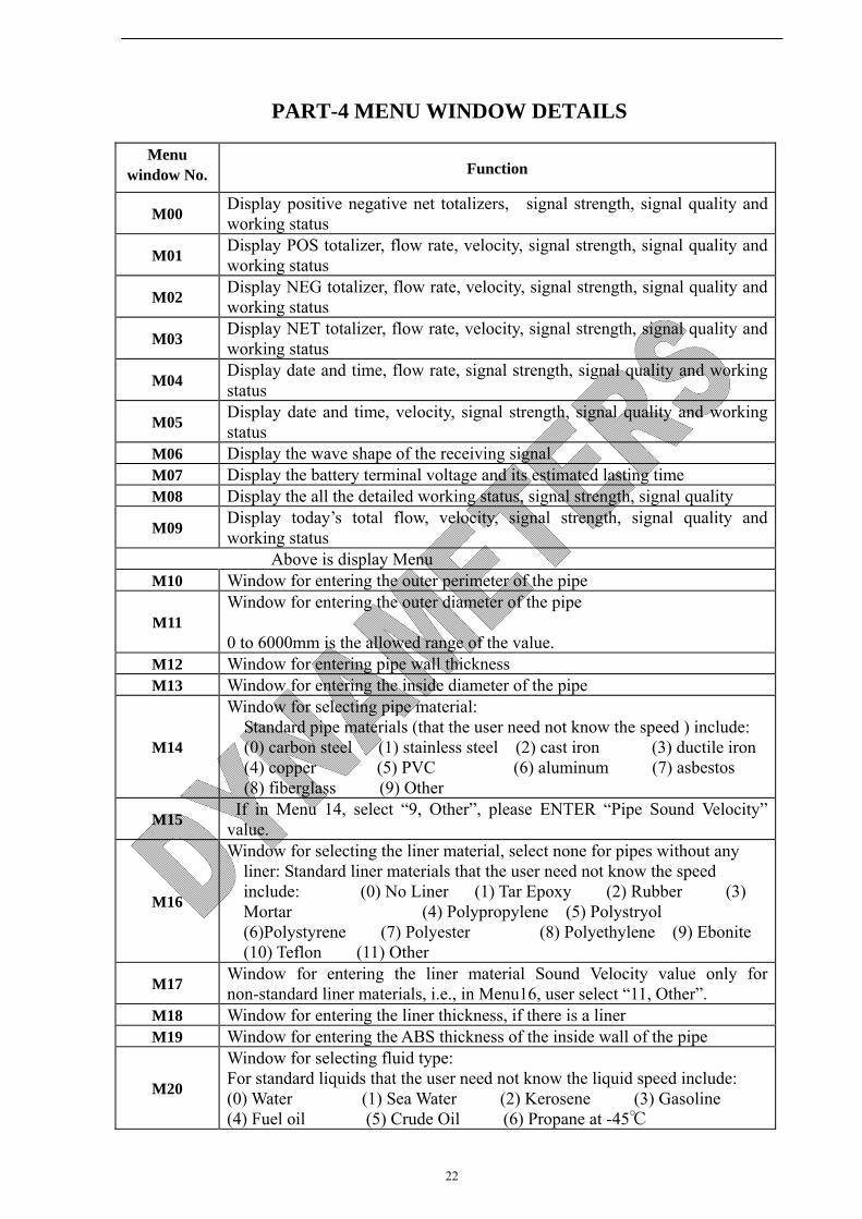
PART-4 MENU WINDOW DETAILS
Menu window No. Function
M00 Display positive negative net totalizers, signal strength, signal quality and working status
M01 Display POS totalizer, flow rate, velocity, signal strength, signal quality and working status
M02 Display NEG totalizer, flow rate, velocity, signal strength, signal quality and working status
M03 Display NET totalizer, flow rate, velocity, signal strength, signal quality and working status
M04 Display date and time, flow rate, signal strength, signal quality and working status
M05 Display date and time, velocity, signal strength, signal quality and working status
M06 Display the wave shape of the receiving signal M07 Display the battery terminal voltage and its estimated lasting time M08 Display the all the detailed working status, signal strength, signal quality
M09 Display today’s total flow, velocity, signal strength, signal quality and working status
Above is display Menu M10 Window for entering the outer perimeter of the pipe
M11 Window for entering the outer diameter of the pipe
0 to 6000mm is the allowed range of the value. M12 Window for entering pipe wall thickness M13 Window for entering the inside diameter of the pipe
M14
Window for selecting pipe material: Standard pipe materials (that the user need not know the speed ) include: (0) carbon steel (1) stainless steel (2) cast iron (3) ductile iron (4) copper (5) PVC (6) aluminum (7) asbestos (8) fiberglass (9) Other
M15 If in Menu 14, select “9, Other”, please ENTER “Pipe Sound Velocity” value.
M16
Window for selecting the liner material, select none for pipes without any liner: Standard liner materials that the user need not know the speed include: (0) No Liner (1) Tar Epoxy (2) Rubber (3) Mortar (4) Polypropylene (5) Polystryol (6)Polystyrene (7) Polyester (8) Polyethylene (9) Ebonite (10) Teflon (11) Other
M17 Window for entering the liner material Sound Velocity value only for non-standard liner materials, i.e., in Menu16, user select “11, Other”.
M18 Window for entering the liner thickness, if there is a liner M19 Window for entering the ABS thickness of the inside wall of the pipe
M20
Window for selecting fluid type: For standard liquids that the user need not know the liquid speed include: (0) Water (1) Sea Water (2) Kerosene (3) Gasoline (4) Fuel oil (5) Crude Oil (6) Propane at -45℃
23
(7) Butane at 0℃ (8)Other liquids (9) Diesel Oil (10)Caster Oil (11)Peanut Oil (12) #90 Gasoline (13) #93 Gasoline (14) Alcohol (15) Hot water at 125℃
M21 Window for entering the fluid sound speed only for non-standard liquids, i.e., in Menu20, user select “8, Other Liquids”.
M22 Window for entering the viscosity of the non-standard liquids
M23
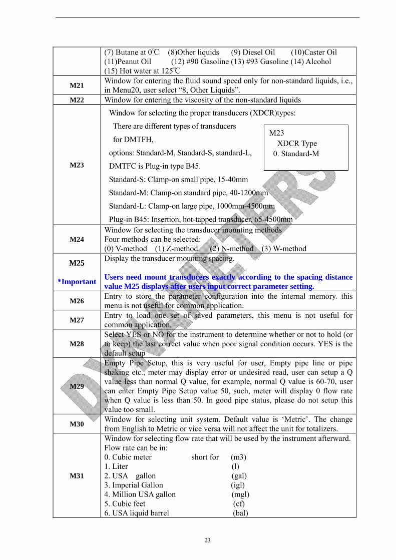
Window for selecting the proper transducers (XDCR)types:
There are different types of transducers
for DMTFH,
options: Standard-M, Standard-S, standard-L,
DMTFC is Plug-in type B45.
Standard-S: Clamp-on small pipe, 15-40mm
Standard-M: Clamp-on standard pipe, 40-1200mm
Standard-L: Clamp-on large pipe, 1000mm-4500mm
Plug-in B45: Insertion, hot-tapped transducer, 65-4500mm
M24 Window for selecting the transducer mounting methods Four methods can be selected: (0) V-method (1) Z-method (2) N-method (3) W-method
M25
*Important
Display the transducer mounting spacing.
Users need mount transducers exactly according to the spacing distance value M25 displays after users input correct parameter setting.
M26 Entry to store the parameter configuration into the internal memory. this menu is not useful for common application.
M27 Entry to load one set of saved parameters, this menu is not useful for common application.
M28 Select YES or NO for the instrument to determine whether or not to hold (or to keep) the last correct value when poor signal condition occurs. YES is the default setup
M29
Empty Pipe Setup, this is very useful for user, Empty pipe line or pipe shaking etc., meter may display error or undesired read, user can setup a Q value less than normal Q value, for example, normal Q value is 60-70, user can enter Empty Pipe Setup value 50, such, meter will display 0 flow rate when Q value is less than 50. In good pipe status, please do not setup this value too small.
M30 Window for selecting unit system. Default value is ‘Metric’. The change from English to Metric or vice versa will not affect the unit for totalizers.
M31
Window for selecting flow rate that will be used by the instrument afterward. Flow rate can be in: 0. Cubic meter short for (m3) 1. Liter (l) 2. USA gallon (gal) 3. Imperial Gallon (igl) 4. Million USA gallon (mgl) 5. Cubic feet (cf) 6. USA liquid barrel (bal)
M23 XDCR Type
0. Standard-M

24
7. Imperial liquid barrel (ib) 8. Oil barrel (ob) The flow unit in terms of time can be per day, per hour, per minute or per second. So there are 36 different flow rate units in total for selection.
M32 Window for selecting the totaliziers’ working unit
M33 Select totalizer multiplier The multiplier ranges from 0.001 to 10000
M34 Turn on or turn off the NET totalizer M35 Turn on or turn off the POS totalizer M36 Turn on or turn off the NEG totalizer
M37
(1) Totalizer reset (2) Restore the instrument to the default parameters as the manufacturer did (Reset system) by pressing the dot key . followed by the ◀ key. Take care or make note on the parameters before doing the restoration .
M38 Press-a-key-to-run or to stop totalizer for easier calibration application etc.
M40 Flow rate damper for a stable value. The input range is 0 to 999 seconds. 0 means there is no damping. Default value is 10 seconds
M41
Low Flow Cutoff, may be used in order to force a zero display at
lower flows and avoid
incorrect totalization.
For instance, this value is 0.02m/s,
the meter will display zero when flow rate is less than ±0.02m/s.
M42
Set Zero, when the fluid is in the static state, the displayed value is
called “zero point”. When the “Zero Point” is not really at zero, the
incorrect read value is going to be added into the actual flow values. Set Zero must be carried out after the transducers are right installed and the flow inside is in the absolute static state (no liquid moved in the pipe line). Set Zero also is very important step when recalibrating the meter in lab. Doing this step enhances the measuring accuracy and flow offset can be eliminated.
M43 Clear the zero point set by the user, and restore the zero point set by the manufacturer
M44 Set up a manual flow bias. Generally this value should be 0.
M45
The Scale Factor is used to modify the measurement results, factory default is 1.0 or other value depend on calibration, please see the calibration data sheet and save this sheet. If really necessary, the user can enter a numerical value other than factory default value according to re-calibration results.
M46
Network environment Identification Number. Any integer can be entered except 13(0DH, carriage return), 10 (0AH, line feeding), 42 (2AH), 38, 65535. Every set of the instrument in a network environment should have a unique IDN. Please refer to the chapter for communication.
M47 System locker to avoid modification of the parameters (The universal password is 0808)
M49 Communication tester M50 “Option” selection for the built-in logger. It also functions as the switch of
M41 Low Flow Cutoff 0.02m/s

25
external 512M data logger. If select data logger output, please select “ON”, then, press “ENTER”, then must select all the items “ON”, i.e., from item 1 to 11, all the items must be selected as “ON”.
M51
Time setup for the data logger, read the ADDENDUM 2 DATA
LOGGER AND ANALYSE SOFTWARE USAGE, 2.7 Q/A, If “Go On” time
is longer than 24 hours, please use dot key . on Keypad, will display
* symbol, as below: **:**:**, it means no time limit.
M52
(1) Data logging direction control, use the ∧ or ∨ key to select ‘To RS-232’ , then press “ENTER” key, all the data produced by the data logger will be transmitted out through the RS-232 interface
(2) If ‘To buffer ‘ is selected, the data will be stored into the built-in logger memory
(3) Buffer transferring and buffer clearing
M53 Logger buffer viewer. It functions as a file editor. Use Dot, backspace UP and DN keys to browse the buffer. If the logger is ON, the viewer will automatically refresh once new data are stored
M60 99-year calendar. Press ENTER for modification. Use the dot key to skip the digits that need no adjusting. User can setup Date as YEAR-MONTH-D (all setups are two digits.)
M61 Display Version information and Electronic Serial Number (ESN) that are unique for each DMTFH series flow meter. The users can employ the ESN for instrumentation management.
M62
RS-232C communication setup
Commonly, user should select “9600, None”
9600 is baud rate; parity check bit is “None”.
M67 Input the frequency range for the frequency output. The biggest range is 0Hz-9999Hz. Default value is 1-1001 Hz. Note: see the next page for OCT terminal wiring.
M68
Setup the Low Frequency Output
corresponding Value of Flow Rate.
This value correspond to the lowest
Frequency value entered in M67.
M69
Setup the High Frequency Output
corresponding Value of Flow Rate.
This value correspond to the highest
Frequency value entered in M67.
M70 LCD display backlight control. The entered value indicates how many
seconds the backlight will be on with every key pressing.
M71 LCD contrast control. The LCD will become darker when a small value is
M68 Low FO Flow Rate 0 m3/h
M69 High FO Flow Rate 3000 m3/h

26
entered.
M72 Working timer. It can be cleared by pressing ENT key, and then select
YES.
M73
Enter Lower Flow Rate value that will trigger the #1 Alarm. There are
two virtual alarms in the system. By “virtual” we mean that the user
must redirect the output of the alarms by setting up the output hardware
in M78 and M77
M74 Enter the higher flow rate value that will trigger the #1 Alarm.
M75 Enter the lower flow rate value that will trigger the #2 Alarm.
M76 Enter the higher flow rate value that will trigger the #2 Alarm.
M77 Buzzer setup. If a proper input source is selected, the buzzer will beep
when the trigger event occurs
M78 OCT (Open Collect Transistor )Output setup: By selecting a proper input source, the OCT hardware will close when the trigger event occurs
M90
Display signal strength, signal quality,
IMPORTANT
When installing the transducers,
Let Q Value at least ≥60
M91
Displays the Time Ratio between the Measured Total Transit Time
and the Calculated time. If the pipe parameters are entered correctly
and the transducers are properly installed, the ratio value should be in
the range of 100±3%. Otherwise the entered parameters and the
transducer installation should be checked.
M92
Displays the measured fluid sound speed. Normally this value should be approximately equal to the entered value in Menu 21 when M20 the fluid type select “Other”. If this value has an obvious difference with the actual fluid sound speed, pipe parameters entered and the transducer installation should be checked again. If Menu20, the fluid type doesn’t select “Other”, this window is no matter with user.
M93 Displays total transit time and delta time(transit time difference)
M94 Displays the Reynolds number and the pipe factor used by the flow rate program.
M+0 Browse the 64 recorded instrument power-on and power-off date and time with the flow rate at the time of power on and off
M91 TOM/TOS*100 0.0000%
M90 Strength + Quality S=00.0, 00.0 Q=00

27
M+1 Displays the total working time of the instrument M+2 Displays the last power-off date and time M+3 Displays the last power-off flow rate
M+4 Displays the times of instrument powered on(the instrument has been powered on)
M+5 A scientific calculator for the convenience of field working. All the values are in single accuracy. The drawback is that the user can’t operate it by direct key-pressing
M+8 Ultrasonic Wave Shape
Note: The pulse output is utilized to transmit information to external counters and PID systems via a frequency output that is proportional to system flow rate or total flow (can be configured in Menu). The frequency output range of the Pulse is 0–9999 Hz. The type of pulse output is an open-collector transistor (OCT) type that does not source voltage at its output, requiring an external power source and pull-up resistor. Resistor selection is based on the input impedance of the receiving device. Select a resistor that is a maximum of 10% of the input impedance of the receiving device, but do not exceed 10k-ohms. See the Figure 3.3, the voltage value of External DC power Supply is depending on Pulse Output receiver, 3-12V is allowable.

28
PART-5 TROUBLESHOOTING
5.1 POWER-ON ERROR DISPLAYS AND COUNTER-MEASURES
The DMTFH series ultrasonic flow meter provides an automatic power-on diagnosis for the hardware problems. When any message (with the power on) in the following table displays, counter-measures should be taken.
5.2 ERROR CODE AND COUNTER-MEASURES
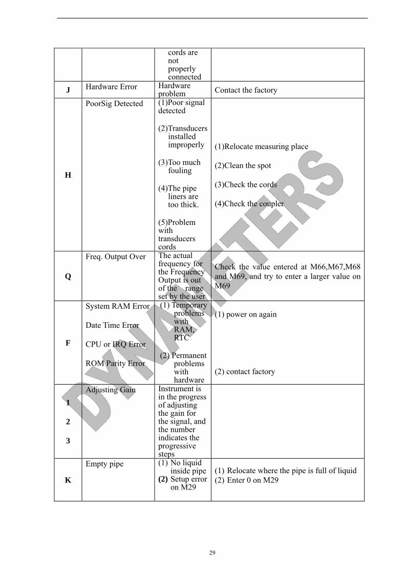
The DMTFH series ultrasonic flow meter will show Error Code in the lower right corner with a single letter like I, R etc. on menu windows M00, M01, M02, M03, M90 and M08. When any abnormal Error Code shows, counter-measures should be taken.
Error
code
Correspondent Message displayed on M08
Causes
Counter-measures R System Normal No error
I
Detect No Signal (1)No Signals detected
(2)Transducers installed improperly
(3)Too much fouling
(4)Pipe liners are too thick.
(5)Transducer
(1)Relocate measuring location
(2)Clean the spot
(3)Check the cords
Error message causes Counter-measures ROM Testing Error
Segment Test Error
Problem with the software
(1)Power on again
(2)Contact with factory
Stored Data Error
The parameters entered by the user lose integration.
When this message displays, the user should press ENT key, and all the configuration will be restored to the default state.
Timer Slow Error
Timer Fast Error
Problem with the timer-keeper or the crystal oscillator.
(1)Power on again
(2)Contact with factory
Date Time Error Number errors with the calendar
Initialize the calendar by menu window M61
Reboot repetitively Hardware problems
Contact the factory
29
cords are not properly connected
J Hardware Error Hardware problem Contact the factory
H
PoorSig Detected (1)Poor signal detected
(2)Transducers installed improperly
(3)Too much fouling
(4)The pipe liners are too thick.
(5)Problem with transducers cords
(1)Relocate measuring place
(2)Clean the spot
(3)Check the cords
(4)Check the coupler
Q
Freq. Output Over The actual frequency for the Frequency Output is out of the range set by the user
Check the value entered at M66,M67,M68 and M69, and try to enter a larger value on M69
F
System RAM Error
Date Time Error
CPU or IRQ Error
ROM Parity Error
(1) Temporary problems with RAM, RTC
(2) Permanent problems with hardware
(1) power on again
(2) contact factory
1
2
3
Adjusting Gain Instrument is in the progress of adjusting the gain for the signal, and the number indicates the progressive steps
K
Empty pipe (1) No liquid inside pipe
(2) Setup error on M29
(1) Relocate where the pipe is full of liquid (2) Enter 0 on M29
30
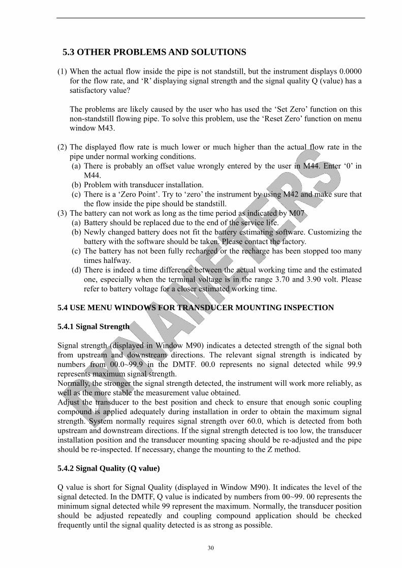
5.3 OTHER PROBLEMS AND SOLUTIONS
(1) When the actual flow inside the pipe is not standstill, but the instrument displays 0.0000 for the flow rate, and ‘R’ displaying signal strength and the signal quality Q (value) has a satisfactory value?
The problems are likely caused by the user who has used the ‘Set Zero’ function on this non-standstill flowing pipe. To solve this problem, use the ‘Reset Zero’ function on menu window M43.
(2) The displayed flow rate is much lower or much higher than the actual flow rate in the pipe under normal working conditions. (a) There is probably an offset value wrongly entered by the user in M44. Enter ‘0’ in
M44. (b) Problem with transducer installation. (c) There is a ‘Zero Point’. Try to ‘zero’ the instrument by using M42 and make sure that
the flow inside the pipe should be standstill. (3) The battery can not work as long as the time period as indicated by M07
(a) Battery should be replaced due to the end of the service life. (b) Newly changed battery does not fit the battery estimating software. Customizing the
battery with the software should be taken. Please contact the factory. (c) The battery has not been fully recharged or the recharge has been stopped too many
times halfway. (d) There is indeed a time difference between the actual working time and the estimated
one, especially when the terminal voltage is in the range 3.70 and 3.90 volt. Please refer to battery voltage for a closer estimated working time.
5.4 USE MENU WINDOWS FOR TRANSDUCER MOUNTING INSPECTION
5.4.1 Signal Strength Signal strength (displayed in Window M90) indicates a detected strength of the signal both from upstream and downstream directions. The relevant signal strength is indicated by numbers from 00.0~99.9 in the DMTF. 00.0 represents no signal detected while 99.9 represents maximum signal strength. Normally, the stronger the signal strength detected, the instrument will work more reliably, as well as the more stable the measurement value obtained. Adjust the transducer to the best position and check to ensure that enough sonic coupling compound is applied adequately during installation in order to obtain the maximum signal strength. System normally requires signal strength over 60.0, which is detected from both upstream and downstream directions. If the signal strength detected is too low, the transducer installation position and the transducer mounting spacing should be re-adjusted and the pipe should be re-inspected. If necessary, change the mounting to the Z method. 5.4.2 Signal Quality (Q value) Q value is short for Signal Quality (displayed in Window M90). It indicates the level of the signal detected. In the DMTF, Q value is indicated by numbers from 00~99. 00 represents the minimum signal detected while 99 represent the maximum. Normally, the transducer position should be adjusted repeatedly and coupling compound application should be checked frequently until the signal quality detected is as strong as possible.
31
5.4.3 Total Time and Delta Time “Total Time and Delta Time”, which displays in Window No.93, indicates the condition of the installation. The measurement calculations in the flow meter are based upon these two parameters. Therefore, when “Delta Time” fluctuates widely, the flow and velocities fluctuate accordingly. This means that the signal quality detected is too poor. It may be the resulted of poor pipe-installation conditions, inadequate transducer installation or incorrect parameter input. Generally, “Delta Time” fluctuation should be less than ±20%. Only when the pipe diameter is too small or velocity is too low can the fluctuation be wider. 5.4.4 Transit Time Ratio (M91, Very important for transducer mounting spacing) Transit Time Ratio indicates if the transducer mounting spacing is accurate. The normal transit time ratio should be 100±3% if the installation is proper. Check it in Window M91.If the transit time ratio is over 100±3%, it is necessary to check (1) if the parameters (pipe outside diameter, wall thickness, pipe material, liner, etc.) have been entered correctly, (2) if the transducer mounting spacing is in accordance with the display in Window M25, (3) if the transducer is mounted at the pipe’s centerline on the same diameter, or (4) if the scale is too thick or the pipe mounting is distorted in shape, etc. 5.4.5 Warnings 1. Pipe parameters entered must be accurate; otherwise the flow meter will not work properly. 2. During the installation, apply enough coupling compounds in order to stick the transducer onto the pipe wall. While checking the signal strength and Q value, move the transducer slowly around the mounting site until the strongest signal and maximum Q value can be obtained. Make sure that the larger the pipe diameter, the more the transducer should be moved. Check to be sure the mounting spacing is accordance with the display in Window M25 and the transducer is mounted at the pipe’s centerline on the same diameter. Pay special attention to those pipes that formed by steel rolls (pipe with seams), since such pipe is always irregular. If the signal strength is always displayed as 0.00, that means there is no signal detected. Thus, it is necessary to check that the parameters (including all the pipe parameters) have been entered accurately. Check to be sure the transducer mounting method has been selected properly, the pipe is not worn-out, and the liner is not too thick. Make sure there is there is indeed fluid in the pipe or the transducer is not very close to a valve or elbow, and there are not too many air bubbles in the fluid, etc. With the exception of these reasons, if there is still no signal detected, the measurement site has to be changed. 3. Make sure that the flow meter is able to run properly with high reliability. The stronger the signal strength displayed, the higher the Q value reached. The longer the flow meter runs accurately, the higher the reliability of the flow rates displayed. If there is interference from ambient electromagnetic waves or the signal detected is too poor, the flow value displayed is not reliable; consequently, the capability for reliable operation is reduced. 4. After the installation is complete, power on the instrument and check the result accordingly.
32
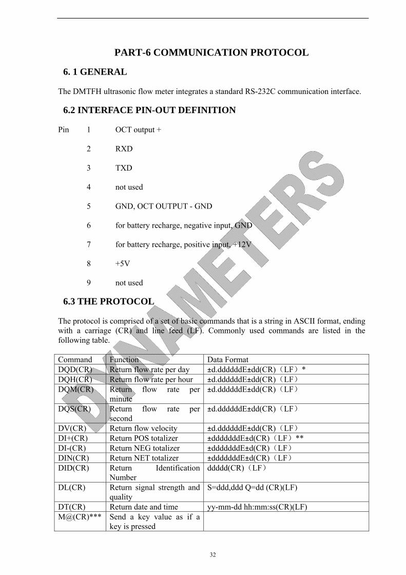
PART-6 COMMUNICATION PROTOCOL
6. 1 GENERAL
The DMTFH ultrasonic flow meter integrates a standard RS-232C communication interface.
6.2 INTERFACE PIN-OUT DEFINITION
Pin 1 OCT output +
2 RXD
3 TXD
4 not used
5 GND, OCT OUTPUT - GND
6 for battery recharge, negative input, GND
7 for battery recharge, positive input, +12V
8 +5V
9 not used
6.3 THE PROTOCOL
The protocol is comprised of a set of basic commands that is a string in ASCII format, ending with a carriage (CR) and line feed (LF). Commonly used commands are listed in the following table.
Command Function Data Format DQD(CR) Return flow rate per day ±d.ddddddE±dd(CR)(LF)* DQH(CR) Return flow rate per hour ±d.ddddddE±dd(CR)(LF) DQM(CR) Return flow rate per
minute ±d.ddddddE±dd(CR)(LF)
DQS(CR) Return flow rate per second
±d.ddddddE±dd(CR)(LF)
DV(CR) Return flow velocity ±d.ddddddE±dd(CR)(LF) DI+(CR) Return POS totalizer ±dddddddE±d(CR)(LF)** DI-(CR) Return NEG totalizer ±dddddddE±d(CR)(LF) DIN(CR) Return NET totalizer ±dddddddE±d(CR)(LF) DID(CR) Return Identification
Number ddddd(CR)(LF)
DL(CR) Return signal strength and quality
S=ddd,ddd Q=dd (CR)(LF)
DT(CR) Return date and time yy-mm-dd hh:mm:ss(CR)(LF) M@(CR)*** Send a key value as if a
key is pressed
33
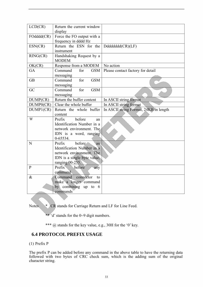
LCD(CR) Return the current window display
FOdddd(CR) Force the FO output with a frequency in dddd Hz
ESN(CR) Return the ESN for the instrument
Dddddddd(CR)(LF)
RING(CR) Handshaking Request by a MODEM
OK(CR) Response from a MODEM No action GA Command for GSM
messaging Please contact factory for detail
GB Command for GSM messaging
GC Command for GSM messaging
DUMP(CR) Return the buffer content In ASCII string format DUMP0(CR) Clear the whole buffer In ASCII string format DUMP1(CR) Return the whole buffer
content In ASCII string Format, 24KB in length
W Prefix before an Identification Number in a network environment. The IDN is a word, ranging 0-65534.
N Prefix before an Identification Number in a network environment. The IDN is a single byte value, ranging 00-255.
P Prefix before any command
& Command connector to make a longer command by combining up to 6 commands
Notes * CR stands for Carriage Return and LF for Line Feed.
** ‘d’ stands for the 0~9 digit numbers.
*** @ stands for the key value, e.g., 30H for the ‘0’ key.
6.4 PROTOCOL PREFIX USAGE
(1) Prefix P
The prefix P can be added before any command in the above table to have the returning data followed with two bytes of CRC check sum, which is the adding sum of the original character string.

34
Take the DI+(CR) command as an example. Assume that DI+(CR) would return +1234567E+0m3(CR)(LF)( the string in hexadecimal is 2BH, 31H, 32H, 33H, 34H, 35H, 36H, 37H, 45H, 2BH, 30H, 6DH, 33H, 20H, 0DH, 0AH) , then PDI(CR) would return +1234567E+0m3!F7(CR)(LF). ‘!’ acts as the starter of check sum which is yielded by adding up the string 2BH, 31H, 32H, 33H, 34H, 35H, 36H, 37H, 45H, 2BH, 30H, 6DH, 33H, 20H.
Please note that there will be SPACES (20H) before ‘!’.
(2) Prefix W
The prefix W should be used in the network environment. The usage format is W + digit string which stands for the IDN (Identification Number of the meter) + basic command.
The digit string should have a value between 0 and 65534 except 13(0DH), 10 (0AH), 42(2AH,*), 38(26H, &).
For example, if the IDN=254 instrument is addressed and returning the velocity of that instrument is requested, the command will be W254DV(CR).
(3) Prefix N
The prefix N is a single byte IDN network prefix, not recommended in a new design. It is reserved only for the purpose of the compatibility with the former versions
(4) Command Connector &
The & command connector can connect up to 6 basic commands to form a longer command so that it will make the programming much easier.
For example, assume that the measurement of an instrument with DID=254 are going to be returned, and (then) all the following 3 values--- (1) flow rate (2) velocity (3)POS totalizer---will be returned simultaneously. The combined command would be W254DQD&DV&DI+(CR), and the result would be:
+1.234567E+12m3/d(CR)
+3.1235926E+00m/s(CR)
+1234567E+0m3(CR)
6.5 CODES FOR THE KEYPAD
The codes for the keypad should be used when the instrument is connected with other terminals that operate the instrument by transmitting the ‘M’ command along with the keypad code. By this function, remote operation of this instrument can be realized, even via the Internet.
Key
HexadecimalKey code
Decimal Key code
ASCII
Code
Key Hexadecimal
Key code
Decimal Key code
ASCII
Code
0
30H 48 0
8 38H 56 8
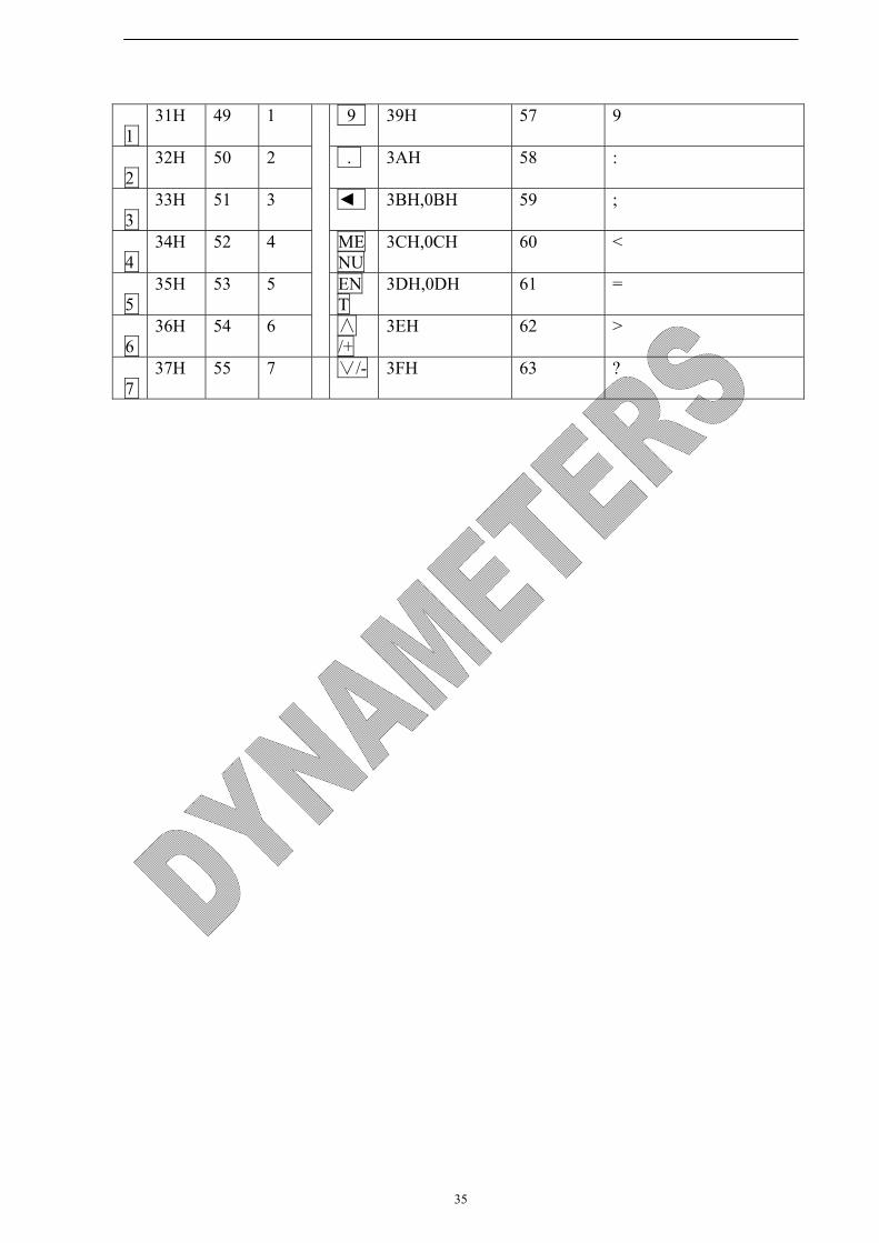
35
1
31H 49 1 9 39H 57 9
2
32H 50 2 . 3AH 58 :
3
33H 51 3 ◄ 3BH,0BH 59 ;
4
34H 52 4 MENU
3CH,0CH 60 <
5
35H 53 5 ENT
3DH,0DH 61 =
6
36H 54 6 ∧/+
3EH 62 >
7
37H 55 7 ∨/- 3FH 63 ?
36
PART-7 WARRANTY AND SERVICE
7.1 WARRANTY
The manufacturer provides one year warranty on all products, free of charge, but the users should be responsible for the one-way transportation fee from the customer to the factory.
7.2 SERVICE
The manufacturer provides instrument installation for our customers, and the charges will be made according the cost.
(1) For any hardware failure of the instrument, we recommend that our customers send back the instrument to our factory for service, due to the fact that the instrument is made of microprocessors and it will be difficult to perform field maintenance. Before sending back the instrument, please try to contact the factory first to make sure what the problem is.
(2) For other operational problems, please contact our local distributor by telephone, fax or email. In most cases, the problem could be solved immediately.

37
APPENDUM 1 FLUID CHARACTERISTIC (SOUND SPEED) TABLE
1 FLUID PROPERITIES Fluid Specific
Gravity Sound Speed delta-v/degree
C Kinematic Viscosity
Absolute viscosity
20 degrees C m/s ft/s m/s/degree C Centistokes Centipoise
Acetate, Butyl
1270 4163.9
Acetate, Ethyl 0.901 1085 3559.7 4.4 0.489 0.441 Acetate, Methyl 0.934 1211 3973.1 0.407 0.380 Acetate, Propyl 1280 4196.7 Acetone 0.79 1174 3851.7 4.5 0.399 0.316 Alcohol 0.79 1207 3960.0 4.0 1.396 1.101 Alcohol, Butyl 0.83 1270 4163.9 3.3 3.239 2.688 Alcohol, Ethyl 0.83 1180 3868.9 4 1.396 1.159 Alcohol, Methyl 0.791 1120 3672.1 2.92 0.695 0.550 Alcohol, Propyl 1170 3836.1 Alcohol, Propyl 0.78 1222 4009.2 2.549 1.988 Ammonia 0.77 1729 5672.6 6.7 0.292 0.225 Anlline 1.02 1639 5377.3 4.0 3.630 3.710 Benzene 0.88 1306 4284.8 4.7 0.711 0.625 Benzol, Ethyl 0.867 1338 4389.8 0.797 0.691 Bromine 2.93 889 2916.7 3.0 0.323 0.946 n-Butane 0.60 1085 3559.7 5.8 Butyrate, Ethyl 1170 3836.1 Carbon dioxide 1.10 839 2752.6 7.7 0.137 0.151 Carbon tetrachloride 1.60 926 3038.1 2.5 0.607 0.968 Chloro-benezene 1.11 1273 4176.5 3.6 0.722 0.799 Chloroform 1.49 979 3211.9 3.4 0.550 0.819 Diethyl ether 0.71 985 3231.6 4.9 0.311 0.222 Diethyl Ketone 1310 4295.1 Diethylene glycol 1.12 1586 5203.4 2.4 Ethanol 0.79 1207 3960.0 4.0 1.390 1.097 Ethyl alcohol 0.79 1207 3960.0 4.0 1.396 1.101 Ether 0.71 985 3231.6 4.9 0.311 0.222 Ethyl ether 0.71 985 3231.6 4.9 0.311 0.222 Ethylene glycol 1.11 1658 5439.6 2.1 17.208 19.153 Freon R12 774.2 2540 Gasoline 0.7 1250 4098.4 Glycerin 1.26 1904 6246.7 2.2 757.100 953.946 Glycol 1.11 1658 5439.6 2.1 Isobutanol 0.81 1212 3976.4 Iso-Butane 1219.8 4002 Isopentane 0.62 980 3215.2 4.8 0.340 0.211 Isopropanol 0.79 1170 3838.6 2.718 2.134 Isopropyl alcohol 0.79 1170 3838.6 2.718 2.134 Kerosene 0.81 1324 4343.8 3.6 Linalool 1400 4590.2
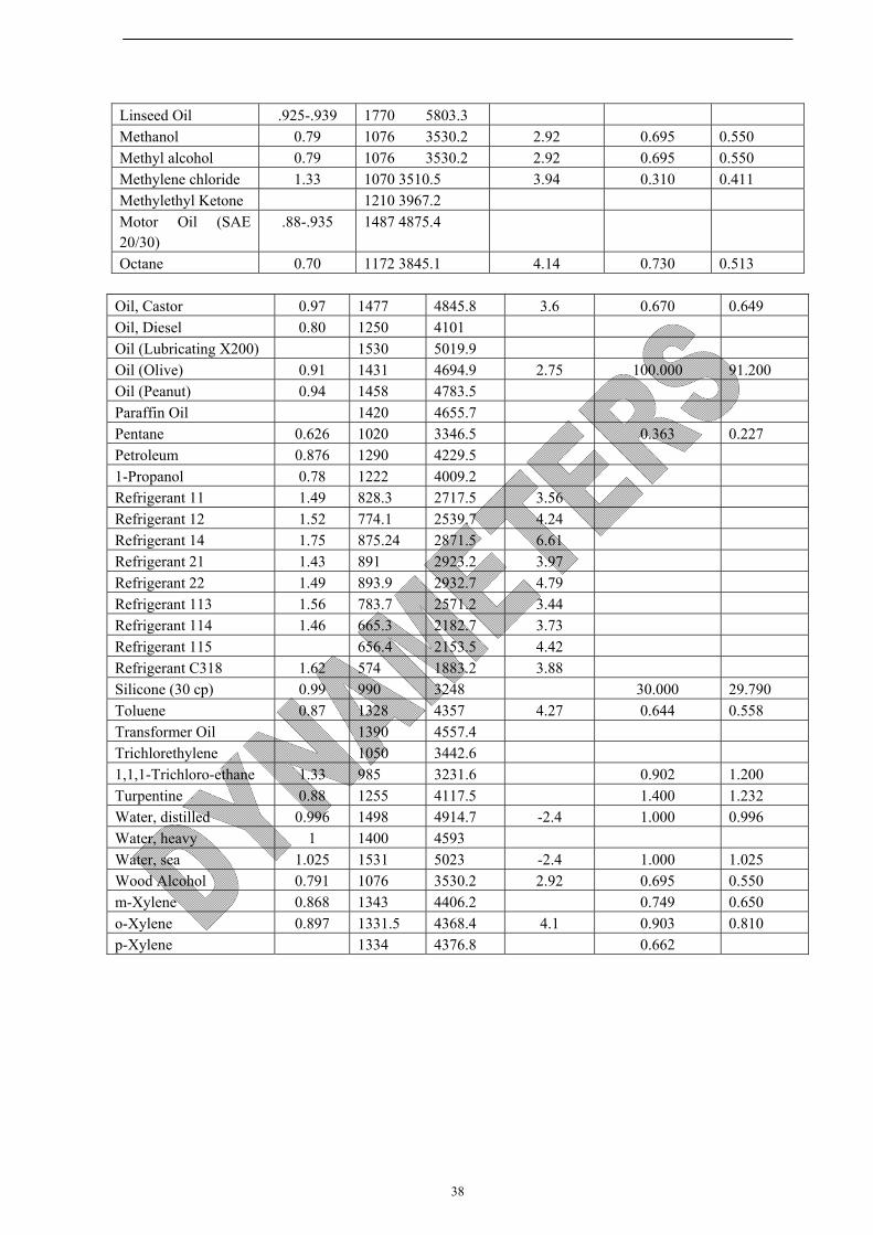
38
Linseed Oil .925-.939 1770 5803.3 Methanol 0.79 1076 3530.2 2.92 0.695 0.550 Methyl alcohol 0.79 1076 3530.2 2.92 0.695 0.550 Methylene chloride 1.33 1070 3510.5 3.94 0.310 0.411 Methylethyl Ketone 1210 3967.2 Motor Oil (SAE 20/30)
.88-.935 1487 4875.4
Octane 0.70 1172 3845.1 4.14 0.730 0.513
Oil, Castor 0.97 1477 4845.8 3.6 0.670 0.649 Oil, Diesel 0.80 1250 4101 Oil (Lubricating X200) 1530 5019.9 Oil (Olive) 0.91 1431 4694.9 2.75 100.000 91.200 Oil (Peanut) 0.94 1458 4783.5 Paraffin Oil 1420 4655.7 Pentane 0.626 1020 3346.5 0.363 0.227 Petroleum 0.876 1290 4229.5 1-Propanol 0.78 1222 4009.2 Refrigerant 11 1.49 828.3 2717.5 3.56 Refrigerant 12 1.52 774.1 2539.7 4.24 Refrigerant 14 1.75 875.24 2871.5 6.61 Refrigerant 21 1.43 891 2923.2 3.97 Refrigerant 22 1.49 893.9 2932.7 4.79 Refrigerant 113 1.56 783.7 2571.2 3.44 Refrigerant 114 1.46 665.3 2182.7 3.73 Refrigerant 115 656.4 2153.5 4.42 Refrigerant C318 1.62 574 1883.2 3.88 Silicone (30 cp) 0.99 990 3248 30.000 29.790 Toluene 0.87 1328 4357 4.27 0.644 0.558 Transformer Oil 1390 4557.4 Trichlorethylene 1050 3442.6 1,1,1-Trichloro-ethane 1.33 985 3231.6 0.902 1.200 Turpentine 0.88 1255 4117.5 1.400 1.232 Water, distilled 0.996 1498 4914.7 -2.4 1.000 0.996 Water, heavy 1 1400 4593 Water, sea 1.025 1531 5023 -2.4 1.000 1.025 Wood Alcohol 0.791 1076 3530.2 2.92 0.695 0.550 m-Xylene 0.868 1343 4406.2 0.749 0.650 o-Xylene 0.897 1331.5 4368.4 4.1 0.903 0.810 p-Xylene 1334 4376.8 0.662
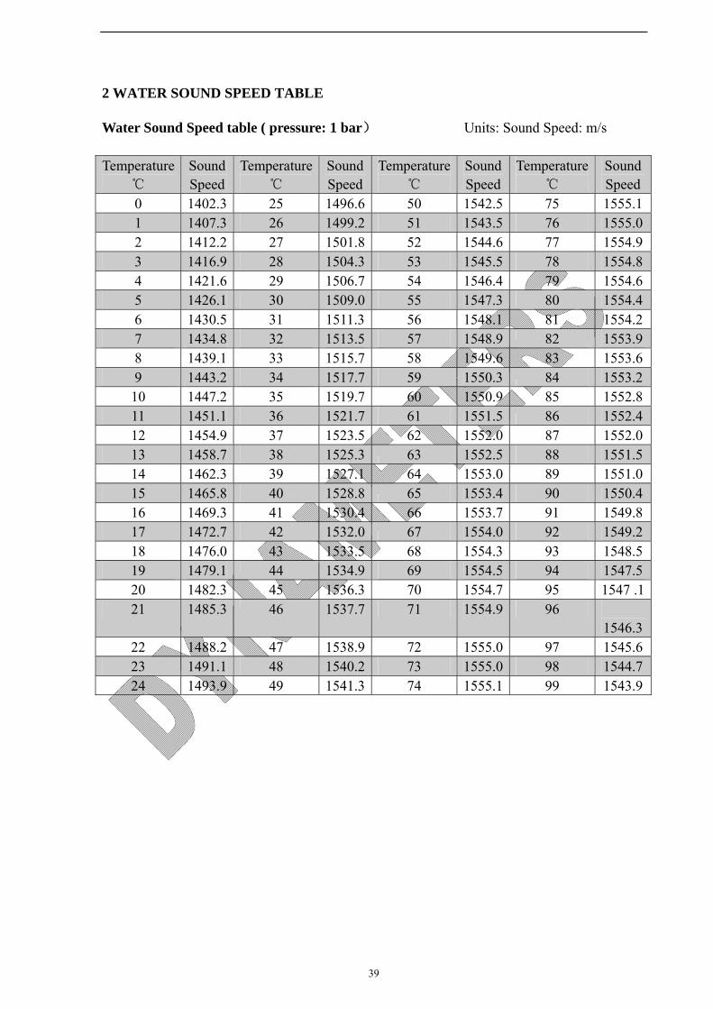
39
2 WATER SOUND SPEED TABLE
Water Sound Speed table ( pressure: 1 bar) Units: Sound Speed: m/s
Temperature℃
Sound Speed
Temperature℃
Sound Speed
Temperature℃
Sound Speed
Temperature ℃
Sound Speed
0 1402.3 25 1496.6 50 1542.5 75 1555.11 1407.3 26 1499.2 51 1543.5 76 1555.02 1412.2 27 1501.8 52 1544.6 77 1554.93 1416.9 28 1504.3 53 1545.5 78 1554.84 1421.6 29 1506.7 54 1546.4 79 1554.65 1426.1 30 1509.0 55 1547.3 80 1554.46 1430.5 31 1511.3 56 1548.1 81 1554.27 1434.8 32 1513.5 57 1548.9 82 1553.98 1439.1 33 1515.7 58 1549.6 83 1553.69 1443.2 34 1517.7 59 1550.3 84 1553.210 1447.2 35 1519.7 60 1550.9 85 1552.811 1451.1 36 1521.7 61 1551.5 86 1552.412 1454.9 37 1523.5 62 1552.0 87 1552.013 1458.7 38 1525.3 63 1552.5 88 1551.514 1462.3 39 1527.1 64 1553.0 89 1551.015 1465.8 40 1528.8 65 1553.4 90 1550.416 1469.3 41 1530.4 66 1553.7 91 1549.817 1472.7 42 1532.0 67 1554.0 92 1549.218 1476.0 43 1533.5 68 1554.3 93 1548.519 1479.1 44 1534.9 69 1554.5 94 1547.520 1482.3 45 1536.3 70 1554.7 95 1547 .121 1485.3 46 1537.7 71 1554.9 96
1546.322 1488.2 47 1538.9 72 1555.0 97 1545.623 1491.1 48 1540.2 73 1555.0 98 1544.724 1493.9 49 1541.3 74 1555.1 99 1543.9

40
APPENDUM 2 DATA LOGGER AND ANALYSE SOFTWARE USAGE
1. Installation Requirements
1.1 Computer Configuration Requirements
To utilize all the functions of the software perfectly, you should ensure that configuration for your personal computer (PC) MUST be
Hardware
CPU: Pentium III or above Memory: 256MB or above Hard Disk: 200MB or above Software Microsoft Office:inclusive of Access, Excel and Word files Application platform Win 7/Windows Vista/Win2003/WinXP/Win2000
1.2 Installation
Data logger connects to Flow meter: For DMTF dedicated (Fixed), just directly plug in to 9 pins RS232 terminal on electronics board, as below shown:
Figure 1 For DMTF Handheld or Portable, just connect to the 9 pins RS232 terminal of DMTF.

41
Copy documents DYNAMETERS from CD to your PC as shown in Figure 2
Figure 2
Double-click and install the setup.exe file until your computer display “finished”
2. Operation
2.1 Login
Click “Start”, find “Dynameters Ultrasonic Flowmeter Logger”, click it to Open the data logger system and then enter the username and password as below.
Figure 3
User name: Admin Password: dynameters This ID and password should be used by the administrator and can not be edited or deleted.
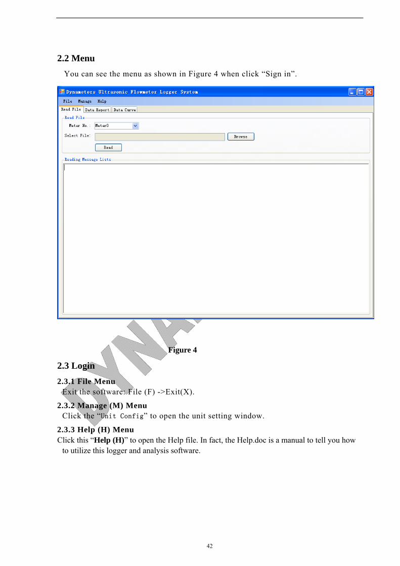
42
2.2 Menu
You can see the menu as shown in Figure 4 when click “Sign in”.
Figure 4
2.3 Login
2.3.1 File Menu Exit the software: File (F) ->Exit(X).
2.3.2 Manage (M) Menu Click the “Unit Config” to open the unit setting window.
2.3.3 Help (H) Menu Click this “Help (H)” to open the Help file. In fact, the Help.doc is a manual to tell you how
to utilize this logger and analysis software.
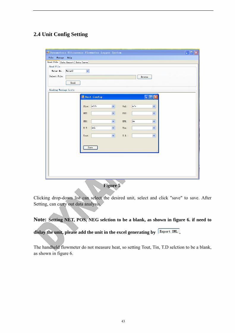
43
2.4 Unit Config Setting
Figure 5
Clicking drop-down list can select the desired unit, select and click "save" to save. After Setting, can carry out data analysis.
Note: Setting NET, POS, NEG selction to be a blank, as shown in figure 6. if need to
dislay the unit, please add the unit in the excel generating by .
The handheld flowmeter do not measure heat, so setting Tout, Tin, T.D selction to be a blank, as shown in figure 6.

44
Figure 6
2.5 Data Analysis Menu
The menu contents three parts: Read File, Data Report and Data Curve (see Figure 7)
Figure 7

45
2.5.1 Read File Menu “Meter_NO.” Option: Use this option, users can select the meter number (from Meter 0 to Meter 9) for data reading (Read File) and data analysis (Data Report & Data Curve). Please Note: The meter number must be same at Read File, Data Report and Data Curve menus. Select File: Click “Browse”, Select the path of reading file: from SD card or other hard disk where the word file of the SD card has been saved.
Figure 8
Click “Read” for the Data reading when ready as shown in Figure 8.
“Data Counts 329 records” means the file has recorded data of 329 times. Note: the Interval Time should be identical in one file. 2.5.2 Data Report Menu
Start Time: the start time of the Data Report Created End Time: the end time of the Data Report Created Select “Meter NO.” for reading file from which Meter Number Click “Create Data Report” to create Data Report when ready (see Figure 9)
Figure 9
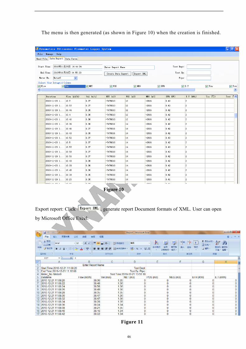
46
The menu is then generated (as shown in Figure 10) when the creation is finished.
Figure 10
Export report: Click , generate report Document formats of XML. User can open
by Microsoft Office Excel.
Figure 11
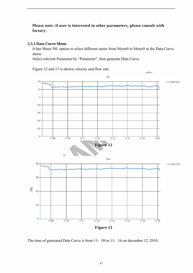
47
Please note: if user is interested in other parameters, please consult with factory.
2.5.3 Data Curve Menu It has Meter N0. option to select different meter from Meter0 to Meter9 in the Data Curve menu. Select relevent Parameter by “Parameter”, then generate Data Curve. Figure 12 and 13 is shown velocity and flow rate.
Figure 12
Figure 13
The time of generated Data Curve is from 11:09 to 11:16 on december 12, 2010.

48
2.5.3.1 The Curve Based On The Different Meter Over The Same Time Period
“Meter_NO.” Option: Select Meter Number “Select Parameters” Option: Select Flow, Velocity, or EFR “Set Time” Option: Select Start time & End time
For example, separately select Meter0 and Meter1 in Meter_NO., Select Flow in Parameter. Click Data Curve to generate flow curve, shown as figure 14.
Figure 14
2.6 Menu Description
“Read File”: Enter the Read File menu “Data Report”: Enter the Data Report menu “Data Curve”: Enter the Data Curve menu
2.7 Q/A
Q: Why doesn’t the Data Logger work normally sometimes? A: Before using the data logger, please check the following items of meter settings (otherwise, the data logger will not work normally): I. In Menu 60, it is time setup for meter, the format should be:
M60
Date 09-08-14
Time 15:16:46

49
YY-MM-DD (For example, it is Aug 14, 2009 today, the Menu 60 setting should be 09-08-14) HH-MM-SS (Hour-minute-second, in 24 hour format) II. In Menu 50 Select Logger Options ON
Then should go on pressing the ENTER key, Items Selections (All the items should be ON) 1. Date and Time ON (If not ON, press ENTER key, then select ON) Then Press "∨-" key 2. System Statue ON Then Press "∨-" key 3. Current Window ON Then Press "∨-" key 4. Flow rate ON Then Press "∨-" key 5. Velocity ON Then Press "∨-" key 6. Net Totalizer ON Then Press "∨-" key
7. POS Totalizer ON Then Press "∨-" key
8. NEG Totalizer ON Then Press "∨-" key 9. Signal Strenth ON Then Press "∨-" key 10. Working Timer
M50
Logger Options
ON
Items Selections
1. Date and Time
ON
Items Selections
2. System Statue
ON
Items Selections
3.Current Window
ON
Items Selections
4. Flow Rate
ON
Items Selections
5. Velocity
ON
Items Selections
6. NET Totalizer
ON
Items Selections
10. Working Timer
ON
Items Selections
9. Signal Strenth
ON
Items Selections
8. NEG Totalizer
ON
Items Selections
7. POS Totalizer
ON

50
ON Then Press "∨-" key 11. Flow Today ON
III. Menu51, you setup start time (later than Menu 60 time, had better at least later 2 minutes), or setting up start time as: Start **:**:** is also Okay. or or IV. Menu 52, Select 0. To RS-232 V. Menu 62 Select Baudrate: =9600 Parity: None Then Press the RESET key on Data Logger keypad. At this time, the Data Light (a green light) on the data logger will flash once at every interval (you setup the interval in Menu 51), which means the data logger works well. IMPORTANT: After pressing the RESET key on data logger keypad, please return the meter to display Menu (Menu 00-Menu 09); otherwise (when meter does not display Menu00-Menu09), the data logger will stop recording data.
Q: What’s the request for settings of the flowmeters when use the Dynameters Data logger?
A: The Data logger of Dynameters for Handheld is different from the Dedicated and Portable series, please care for the difference. Plug in the Data logger, then set up the flowmeter menu, set up the start time, time interval, end time, and correct the flowmeter time.
First correct the flowmeter time in MENU 60, in MENU 50 ,“Logger Option” select “ON”, then set up Start time, time Interval, end end time(Go On) in MENU 51. As follows:
M50
Logger Option
NO
M60
Date 09-01-16
Time 14:01:34
M51 Logger Time
Start 12:30:00
Interval00:05:00
Go On **:**:**
M51 Logger Setup
Start 15:20:00
Intervl 00:00:05
Go On **:**:**
M51 Logger Setup
Start **:**:**
Intervl 00:00:05
Go On **:**:**
M62
RS-232C Setup
Baudrate: =9600
Parity: None
M52
Data Output
0. To RS-232
Items Selections
11. Flow Today
ON
51
If “Go On” time is longer than 24 hours, please use dot key . on Keypad, will display * symbol, as below: **:**:**, it means no time limit. Note: Please care for that the Start time can not be earlier than the time in the flowmeter Menu60.
Menu 62 is RS232C communication setup
user should select “9600, None”
9600 is baud rate; check bit is “None”.
Q: What’s the request for settings of the Dynameters Data logger when use the Dynameters Data logger? A: First plug SD card in the Data Logger. A Reset key and two display lights are on the board of Data Logger. Plug the Data logger in the Rs232 port of the flowmeter, POWER light will flash; this indicates that the Data logger power supply is normal. After Setting up MENU50, MENU51 and MENU60, users must press the Reset key when start recording the Data, indicates it starts recording and creating a file. If change the Data logger Interval in MENU51, you must reset the start time in the MENU50too, then, press the Reset key again. Every time press the Reset key, a file will be created in the SD card. In the same file can not appear different Intervals, or the software can not read Data and Create Data Report. So if the time interval has changed, must press the Reset key.
Q: How to judge the Data Logger works ok, and the SD card start recording Data normally? A: If the Data Logger has started to work normally, every time recording Data, the DATA light on the board will have a flash. If Users wait an Interval time and the DATA light has a flash, this indicates that the Data Logger works ok. If does not flash, please check MENU50 and find out whether the Data Logger is plugged in tightly. If set up Interval time is a little long, waiting time also is long, users can set up a 5 seconds or 10 seconds at first, then press the Reset key, if DATA light flashes, this indicates that the Data Logger works ok. Reset the Start time and a user convenient time Interval, then press Reset key is ok.
Q: what type of SD cards suit to the Dynameters DATA LOGGER? A: There is no limit for storage capacity due to the SD card storage structure. But not all the SD cards in the markets can meet our request, when some SD cards plugged in, DATA light always flash, this indicates that this kind of SD cards can not meet our request. So if need more SD cards or the SD cards are damaged, users can buy from us or have a test to plug SD card in Data Logger, then as above way to judge the Data Logger whether work ok. Moreover, the Lock on the SD card should be unlocked.
Q:Why only the first line has Data in the Data Report, but the others display zero? A:Mainly because in the read word file there is at least 2 Intervals time. If there is 2 time interval in one word file, the software will Create Data Report. So that, if Interval changed in Menu 51, users must press Reset key on Data Logger board.
Q:Why it takes a long time to create the data report?
M62
RS-232C Setup
9600, None
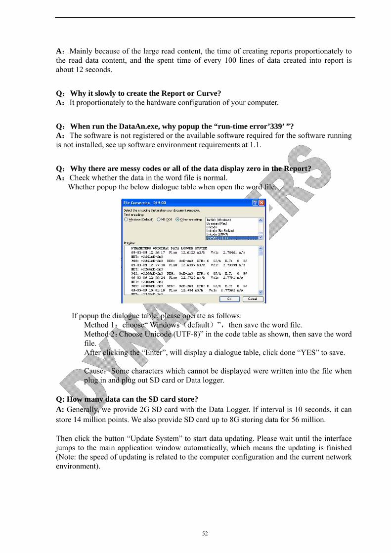
52
A:Mainly because of the large read content, the time of creating reports proportionately to the read data content, and the spent time of every 100 lines of data created into report is about 12 seconds.
Q:Why it slowly to create the Report or Curve? A:It proportionately to the hardware configuration of your computer.
Q:When run the DataAn.exe, why popup the “run-time error’339’ ”? A:The software is not registered or the available software required for the software running is not installed, see up software environment requirements at 1.1.
Q:Why there are messy codes or all of the data display zero in the Report? A:Check whether the data in the word file is normal.
Whether popup the below dialogue table when open the word file.
If popup the dialogue table, please operate as follows:
Method 1:choose“ Windows(default)”,then save the word file. Method 2:Choose Unicode (UTF-8)” in the code table as shown, then save the word file. After clicking the “Enter”, will display a dialogue table, click done “YES” to save.
Cause:Some characters which cannot be displayed were written into the file when plug in and plug out SD card or Data logger.
Q: How many data can the SD card store? A: Generally, we provide 2G SD card with the Data Logger. If interval is 10 seconds, it can store 14 million points. We also provide SD card up to 8G storing data for 56 million. Then click the button “Update System” to start data updating. Please wait until the interface jumps to the main application window automatically, which means the updating is finished (Note: the speed of updating is related to the computer configuration and the current network environment).
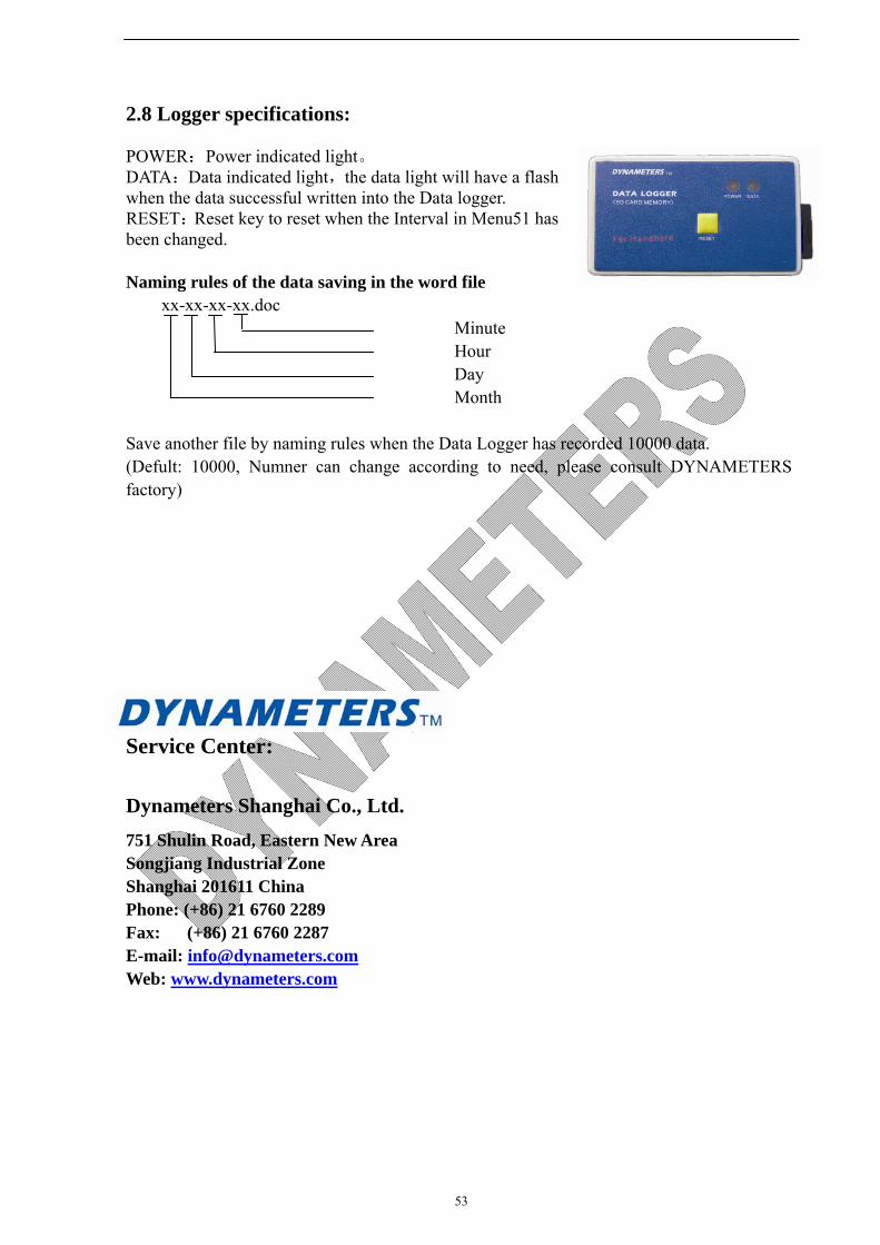
53
2.8 Logger specifications:
POWER:Power indicated light。 DATA:Data indicated light,the data light will have a flash when the data successful written into the Data logger. RESET:Reset key to reset when the Interval in Menu51 has been changed.
Naming rules of the data saving in the word file xx-xx-xx-xx.doc Minute Hour Day Month Save another file by naming rules when the Data Logger has recorded 10000 data. (Defult: 10000, Numner can change according to need, please consult DYNAMETERS factory)
Service Center:
Dynameters Shanghai Co., Ltd.
751 Shulin Road, Eastern New Area Songjiang Industrial Zone Shanghai 201611 China Phone: (+86) 21 6760 2289 Fax: (+86) 21 6760 2287 E-mail: [email protected] Web: www.dynameters.com