dmrb volume 6 section 1 part 1 - td 9/93 - no 1highway
TRANSCRIPT

February 2002
DESIGN MANUAL FOR ROADS AND BRIDGES
VOLUME 6 ROAD GEOMETRYSECTION 1 LINKS
PART 1
TD 9/93 - AMENDMENT NO 1
HIGHWAY LINK DESIGN
SUMMARY
The Standards sets out the elements of design andprinciples for their co-ordination, for geometric designof an existing carriageway or new build situation. TheStandards include a revised Chapter 5 and deletesAnnexes B and C.
INSTRUCTIONS FOR USE
This amendment is to be incorporated in the Manual.
1. Remove existing contents page for Volume 6, andinsert new contents page for Volume 6, datedFebruary 2002.
2. Remove existing cover sheet for Highway LinkDesign and insert new cover sheet.
3. Remove existing TD 9/93 contents sheet andinsert new TD 9/93 Amdt No 1 contents sheet.
4. Remove existing “Detailed contents of Chapters1-8” sheet and insert new sheet dated February2002.
5. Remove existing Chapter 0 “Foreword” pages0/1, 0/2 and 0/3 and insert pages 0/1 and 0/2dated February 2002.
6. Remove existing Chapter 5 (including Annexes Band C), and insert new Chapter 5.
7. Insert the Amendment Sheet at the front of thedocument after the new cover sheet.
8. Enter details of Amendment No 1 on Registrationof Amendment sheet and sign and date toconfirm the amendment has been incorporated.
9. Remove sheets 9/1 and 10/1 and insert newsheets dated February 2002.
10. Archive this sheet as appropriate.
Note: A quarterly index with a full set of VolumeContents Pages is available separately from TheStationery Office Ltd.

TD 9/93IncorporatingAmdt No 1 datedFebruary 2002
Highway Link Design
Summary: The Standards sets out the elements of design and principles for theirco-ordination, for geometric design of an existing carriageway or new buildsituation. The Standards include a revised Chapter 5 and deletes Annexes Band C.
DESIGN MANUAL FOR ROADS AND BRIDGES
THE HIGHWAYS AGENCY
SCOTTISH EXECUTIVE DEVELOPMENT DEPARTMENT
THE NATIONAL ASSEMBLY FOR WALESCYNULLIAD CENEDLAETHOL CYMRU
THE DEPARTMENT FOR REGIONAL DEVELOPMENTNORTHERN IRELAND

Volume 6 Section 1Part 1 TD 9/93 Amendment No 1
February 2002
REGISTRATION OF AMENDMENTS
Amend Page No Signature & Date of Amend Page No Signature & Date ofNo incorporation of No incorporation of
amendments amendments
Registration of Amendments

Volume 6 Section 1Part 1 TD 9/93 Amendment No 1
February 2002
REGISTRATION OF AMENDMENTS
Amend Page No Signature & Date of Amend Page No Signature & Date ofNo incorporation of No incorporation of
amendments amendments
Registration of Amendments

VOLUME 6 ROAD GEOMETRYSECTION 1 LINKS
PART 1
TD 9/93 - AMENDMENT NO 1
HIGHWAY LINK DESIGN
Contents
Chapter
0. Foreword
1. Design Speed
2. Sight Distance
3. Horizontal Alignment
4. Vertical Alignment
5. Climbing Lanes
6. Introduction to Coordinated Link Design
7. Single 2 Lane Carriageway Roads
8. Dual Carriageways and Motorways
9. References
10. Enquiries
Annex A Harmonic Mean Visibility
DESIGN MANUAL FOR ROADS AND BRIDGES
February 2002

Detailed Contents of Chapters 1 to 8
DESIGN MANUAL FOR ROADS AND BRIDGES
ELEMENTS OF DESIGN
Chapter
Page
1. Design Speed
General 1/1Factors Affecting Speed 1/1Selection of Design Speed 1/2Design Speed Related Parameters 1/3Changeover of Design Speed Standards 1/4Connection to Existing Roads 1/4Selection of Parameter Values 1/4Relaxations 1/4Departures 1/6
2. Sight Distance
Stopping Sight Distance 2/1Full Overtaking Sight Distance 2/1Obstructions to Sight Distance 2/1Relaxations 2/2
3. Horizontal Alignment
Road Camber 3/1Superelevation 3/1Desirable Minimum Radius 3/2Relaxations 3/2Appearance and Drainage 3/2Application of Superelevation 3/2Widening on Curves 3/2Lane Width Reductions at Pinch Points 3/3Transitions 3/3The Effect of Sight Distance at Horizontal Curves 3/3
4. Vertical Alignment
Gradients 4/1Vertical Curves 4/1Relaxations 4/2
5. Climbing Lanes
Introduction 5/1Scheme Appraisal 5/1Layout - Single Carriageways 5/6Layout - Dual Carriageways 5/19
February 2002
COORDINATED LINK DESIGN
Chapter
Page
6. Introduction to Coordinated Link Design
General 6/1Rural Roads 6/1Urban Roads 6/1
7. Single 2 Lane Carriageway Roads
General Principles 7/1Overtaking Sections 7/1Non-overtaking Sections 7/5Obstructions to Overtaking 7/5Non-overtaking Crests 7/6Overtaking Value 7/7Horizontal Curve Design 7/9Vertical Curve Design 7/10Junction Strategy 7/10Changes in Carriageway Width 7/13Road Markings 7/14Existing Single Carriageway Improvements 7/14Staged Construction 7/15
8. Dual Carriageways and Motorways
General Principles 8/1All Purpose Dual Carriageways 8/1Motorways 8/2

Volume 6 Section 1Part 1 TD 9/93 Amendment No 1
Chapter 0Foreword
mplementation
.9 This Standard should be used forthwith for theesign of all schemes for the construction and/or
provement of trunk roads currently being preparedrovided that in the opinion of the Overseeingepartment, this would not result in any significant
xpense or delay progress. Design Organisations shouldonfirm its application to particular schemes with theverseeing Department.
cope
.10 A major objective of this Standard is to ensureat designs achieve value for money without any
ignificant effect on safety. The design systems that
0. FOREWORD
Introduction
0.1 This Standard applies to both single and dualcarriageway roads in both urban and rural areas. It shallbe used to derive the Design Speed, and the appropriatevalues of geometric parameters for use in the design ofthe road alignment. It states the basic principles to beused for coordinating the various elements of the roaddesign, which together form the three dimensionaldesign of the road.
0.2 This Standard replaces completely the followingdocuments which are hereby withdrawn:
TD 9/81 Highway Link Design
TD 9/81 Amendment No 1 dated January 1985
TD 9/81 Amendment No 2 dated March 1991
Layout of Roads in Rural Areas (and metricsupplement)
Roads in Urban Areas 1966 (and metric supplement)
Motorway Design Memorandum (1962 et seq)
TA 28/82 Layout of Roads in Rural AreasA guide to revisions 1982
TA 32/82 Roads in Urban AreasRevisions subsequent to “A guide to revisions 1979”
TA 43/84 Highway Link Design
Previous “Chapter 5. Climbing Lanes” has been revisedand Annexes B and C deleted.
0.3 Sections of the Advice Note TA 43/84, HighwayLink Design, are superseded by the changes to thisStandard itemised in Paragraph 0.6 of the Foreword.The Advice Note is hereby withdrawn pending a reviewof this Standard.
0.4 Parts of Chapter 6 and Table 4 were supersededby TD 20/85 “Traffic Flows and Carriageway WidthAssessment” (DMRB 5.1). The superseded text hasbeen removed from Chapter 6 and Table 4.
0.5 The format has been changed to that required forthe Design Manual for Roads and Bridges (DMRB).
TEis
0thcvPa
01234T
0MpbSAbAthD
0ac
I
0dimpDecO
S
0ths
February 2002
he Paragraphs have therefore been renumbered.xcept as noted in Paragraphs 0.6 and 07, the Standard unchanged.
.6 New material has been added to this edition ofe standard updating the approach to be taken when
onsidering the application of alignment parameteralues less than Desirable Minimum. The followingaragraphs have been amended or added to reflect thisnd the changes identified in Paragraph 0.7:
.3 0.4 0.5 0.6 0.7 0.8 0.14 0.15 0.16
.9 1.12 to 1.25 inclusive
.1 2.8 to 2.13 inclusive
.3 3.4 to 3.6 inclusive
.4 to 4.17 inclusiveable 3
.7 All parameters are now based upon Desirableinimum values, except for Sag Curves which have not
reviously had Desirable Minimum values. Valueselow that are expressed in terms of numbers of Designpeed steps below Desirable Minimum. References tobsolute Minimum for other than Sag Curves haveeen deleted. Where existing Standards refer tobsolute Minimum values contained in this Standard,ese shall be taken as one Design Speed step belowesirable Minimum values.
.8 Certain editorial changes have been introduced tossist in the application of the Standards, but withouthanging the Standards.
0/1

Volume 6 Section 1Part 1 TD 9/93 Amendment No 1
Chapter 0Foreword
.14 When issued in 1981, this Standard introducede concept of a hierarchy of permitted values for
eometric layout parameters (visibility, horizontalurvature & vertical curvature). This hierarchy wasased upon Desirable Minimum Standards, with loweralues being known progressively as Relaxations and
have been developed in relation to both Design Speedand the related geometric parameters will result in amuch greater flexibility to achieve economic design indifficult circumstances. In addition, detailed attention isgiven to the design of single carriageway roads, wherethe previous recommendations have been considerably
0thgcbv
February 20020/2
extended to allow greater flexibility for design, withparticular emphasis upon the coordination of designelements to improve safety and overtaking conditions.Overall, the greater flexibility for design introduced bythis Standard will enable more economic design,reducing both the construction costs and the impact ofnew roads and road improvements on the environment.
0.11 Throughout this Standard, there is a continualreference to the use of the cost/benefit programmeCOBA (Scotland - NESA), which shall be used at allstages to test the economic performance of alternativescheme designs.
Interpretation
0.12 The Standards contained in this documentrepresent the various criteria and maximum/minimumlevels of provision whose incorporation in the roaddesign would achieve a desirable level of performancein average conditions in terms of traffic safety,operation, economic and environmental effects. In mostcases, with care, designs can be achieved which do notutilise the lowest levels of design parameters given. Atsome locations on new roads or major improvements,however, it may not be possible to justify even thelowest levels of design parameters in economic orenvironmental terms, due to high costs, low trafficlevels, and environmental damage etc. In such cases,sufficient advantages might justify either a Relaxationwithin the Standards, or in more constrained locations aDeparture from the Standards. The various parametersquoted in this Standard are not, therefore to be regardedas sacrosanct in all circumstances. Relaxations andDepartures should be assessed in terms of their effectson the economic worth of the scheme, the environment,and the safety of the road user. Further details on theuse of Relaxations are given in Chapters 1 to 4.
0.13 Designers should always have regard to the costeffectiveness of the design provision. In some cases,such as gradients, DMRB Volume 13.1 provides amethod of quantifying the economic trade-offsassociated with Relaxations. In others, the implications,particularly in relation to safety may not be quantifiableand the Designer must apply the judgement ofexperience in proposing a Relaxation or Departure.
Departures. Values equal to or higher than DesirableMinimum give consistently safe alignments andminimise journey times. Research had shown that inmany situations safety was no worse with values lowerthan the rigid requirements of the previous Standards.The hierarchy of values enabled a flexible approach tobe applied where the strict application of DesirableMinimum requirements would lead todisproportionately high construction costs or severeenvironmental impact upon people, properties andlandscapes. Successive levels in the hierarchy invokedmore stringent consideration in line with the need tocarefully consider safety.
0.15 During the years since 1981 there have beenmany advances in road layout design. The proceduresfor the assessment of safety and operational aspectshave improved. Further research has strengthened theunderstanding of driver behaviour. Safety audits andother initiatives in the mechanics of assessing andchecking scheme layouts have made the design processmore rigorous and reliable.
0.16 Since 1981, experience has been gained in theapplication of this hierarchy of values and thisexperience indicates that the environmental andfinancial benefits gained from this increased flexibilitycan be considerable. Against this background, the scopefor Relaxations has been increased to allow Designersto consider alignment parameter values that wouldgenerally be approved if they were put to theOverseeing Department as Departure proposals. Thescope for Relaxations is increased by 1 Design Speedstep for Motorways and 2 steps for All Purpose Roads,except for Sag Curves where the increase is 1 step forAll Purpose Roads alone. The Designer is required tocarefully consider the benefits and any potentialdisadvantages of Relaxations. New additional guidanceis included in Chapter 1 describing the approach to betaken to assessing Relaxations. Relaxations areconsidered to conform to Standards.
0.17 In Wales additional Design Guidance is providedin the publications “Roads in Upland Areas: A DesignGuide” and “Roads in Lowland Areas: A DesignGuide”. These are to be treated as Relaxations whichwill be subject to the considerations described inChapter 1 of this Standard.

Volume 6 Section 1 Chapter 1Part 1 TD 9/93 Design Speed
1. DESIGN SPEED
1s
of
General
1.1 The road alignment shall be designed so as toensure that Standards of curvature, visibility,superelevation, etc. are provided for a Design Speedwhich shall be consistent with the anticipated vehiclespeeds on the road. A relatively straight alignment inflat country will generate higher speeds, and thusproduce a higher Design Speed than a more sinuousalignment perhaps located in hilly terrain, or amongstdense land use constraints. There is therefore alwaysinherent economic trade-off between the constructionand environmental costs of alternative alignments ofdifferent Design Speeds, and their user benefits, whicshall be tested by COBA (Scotland - NESA).
Factors Affecting Speed
1.2 Speeds vary according to the impression ofconstraint that the road alignment and layout impart tothe driver. This constraint can be measured by the thrfactors given in Paragraphs 1.3 to 1.5.
ELECTRONIC COPY - NOT
June 1993 PAPER COPIES OF THIS ELECTR
an
h
ee
1.3 Alignment Constraint Ac: This measures thedegree of constraint imparted by the road alignment,and measured by:
Dual Carriageways: Ac = 6.6 + B/10
Single Carriageways:Ac = 12 - VISI/60 + 2B/45
where:
B = Bendiness Degrees/km
VISI = Harmonic Mean Visibility m(see Annex A).
1.4 Layout Constraint Lc: This measures the degreeof constraint imparted by the road cross section, vergewidth, and frequency of junctions and accesses. Tableshows the values of Lc relative to cross section featureand density of access, expressed as the total number junctions,laybys and commercial accesses per km,summed for both sides of the road, where:
L = Low Access numbering 2 to 5 per km
M = Medium Access numbering 6 to 8 per km
H = High Access numbering 9 to 12 per km
Road Type S2 WS2 D2AP D3AP D2M D3M
Carriageway Width Dual Dual(Ex. Metre Strips) 7.3m 11m
6m 7.3m 10mDual 7.3m & Dual 11m
Hard & HardShoulder Shoulder
Degree of Accessand Junctions
H M M L M L M L L L L
Standard VergeWidth
29 26 23 21 19 17 10 9 6 4 0
1.5m Verge 31 28 25 23 There is no research data available for 4 laneSingle Carriageway roads between 12 and 14.6mwidth (S4). In the limited cirumstances for their usedescibed in this document, Design Speed should beestimated asuming a normal D2AP with a LayoutConstraint of 15 - 13 kph
0.5m Verge 33 30
Table 1 Layout Constraint Lc kph
FOR USE OUTSIDE THE AGENCY
ONIC DOCUMENT ARE UNCONTROLLED 1/1

Chapter 1 Volume 6 Section 1Design Speed Part 1 TD 9/93
um
l
ed. If Speedd.
esign1.6
1.5 Mandatory Speed Limits: On rural derestrictedroads, ie. with national speed limits of:
mph kph
Motorways and Dual Carriageways 70 112Single Carriageways 60 96
vehicle speeds are constrained only by the physicalimpression of the road alignment, as described by Acand Lc. The use of mandatory speed limits (togetherwith more confined urban cross-sections) however,restricts speeds below those freely achievable, and wact as a further constraint on speed in addition to thatindicated by Lc.
Selection of Design Speed
1.6 New Rural Roads: Design Speed shall be derivedfrom Figure 1, which shows the variation in speeds forgiven Lc against Ac. The Design Speeds are arrangedbands, ie. 120, 100, 85, etc., within which suffixes Aand B indicate the higher and lower categories of eachband. An initial alignment to a trial Design Speedshould be drawn
e
e
aidcwmsri
ELECTRONIC COPY - NOT
PAPER COPIES OF THIS ELECTR1/2
up, and Ac measured for each section of the routedemonstrating significant changes thereof, over a minim
length of 2 km. The Design Speed calculated from the
choice to identify locations where elements of the initiatrial alignment may be relaxed to achieve cost or
be upgraded, according to the calculated Design Speany changes to road geometry result, then the Designshould be recalculated to check that it has not change
ill 1.7 Existing Rural Road Improvements: (including shortdiversions or bypasses up to about 2 km in length) D
Speed shall be derived in a similar manner to Paragraph
a in
nsuing Ac and Lc should be checked against the initial
nvironmental savings, or conversely where design should
bove, with Ac measured over a minimum length of 2 kmncorporating the improvement, provided there are noiscontinuities such as roundabouts. The strategy for theontiguous sections of road, however, must be consideredhen determining Ac and the cross-sectional design. Itight be unnecessary to provide a full Standard cross-
ection for a minor re-alignment within a low Standardoute, unless it represented a stage of a realisticmprovement strategy.
Layout Constraint Lc Kph
120
100
0
5
10
15
20
25
30
35
85
70
60
DESIGN SPEED
(km/h)
120A
120B
100A
100B
85A
85B
70A
70B
2 4 6 8 10 12 14 16 18 20
Single C/ways Ac < 6.6i.e. only possible on long straight roads or where there is extensive visibility outside the highway.
V50wet
100
90
80
70
60
50
ALIGNMENT CONSTRAINT Ac kph for Dual C/ways = 6.6+B/10
Single C/ways = 12-VISI/60+2B/45
Mea
n S
peed
of L
ight
Veh
icle
s kp
V85wet
Figure 1 Selection of Design Speed (Rural Roads)
FOR USE OUTSIDE THE AGENCY
ONIC DOCUMENT ARE UNCONTROLLED June 1993
Volume 6 Section 1Part 1 TD 9/93
Chapter 1Design Speed
D
1ddMvDrS
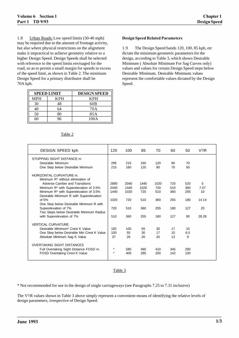
1.8 Urban Roads: Low speed limits (30-40 mph)may be required due to the amount of frontage activity,but also where physical restrictions on the alignmentmake it impractical to achieve geometry relative to ahigher Design Speed. Design Speeds shall be selectedwith reference to the speed limits envisaged for theroad, so as to permit a small margin for speeds in excessof the speed limit, as shown in Table 2. The minimumDesign Speed for a primary distributor shall be70A kph.
SPEED LIMIT DESIGN SPEEDMPH KPH KPH
30 48 60B40 64 70A50 80 85A60 96 100A
Table 2
June 1993
esign Speed Related Parameters
.9 The Design Speed bands 120, 100, 85 kph, etcictate the minimum geometric parameters for theesign, according to Table 3, which shows Desirableinimum ( Absolute Minimum For Sag Curves only)
alues and values for certain Design Speed steps belowesirable Minimum. Desirable Minimum values
epresent the comfortable values dictated by the Designpeed.
Table 3
* Not recommended for use in the design of single carriageways (see Paragraphs 7.25 to 7.31 inclusive)
The V²/R values shown in Table 3 above simply represent a convenient means of identifying the relative levels ofdesign parameters, irrespective of Design Speed.
DESIGN SPEED kph 120 100 85 70 60 50 V2/R
STOPPING SIGHT DISTANCE mDesirable Minimum 295 215 160 120 90 70One Step below Desirable Minimum 215 160 120 90 70 50
HORIZONTAL CURVATURE m.Minimum R* without elimination of Adverse Camber and Transitions 2880 2040 1440 1020 720 520 5Minimum R* with Superelevation of 2.5% 2040 1440 1020 720 510 360 7.07Minimum R* with Superelevation of 3.5% 1440 1020 720 510 360 255 10Desirable Minimum R with Superelevationof 5% 1020 720 510 360 255 180 14.14One Step below Desirable Minimum R withSuperelevation of 7% 720 510 360 255 180 127 20Two Steps below Desirable Minimum Radiuswith Superelevation of 7% 510 360 255 180 127 90 28.28
VERTICAL CURVATUREDesirable Minimum* Crest K Value 182 100 55 30 17 10One Step below Desirable Min Crest K Value 100 55 30 17 10 6.5Absolute Minimum Sag K Value 37 26 20 20 13 9
OVERTAKING SIGHT DISTANCESFull Overtaking Sight Distance FOSD m. * 580 490 410 345 290FOSD Overtaking Crest K Value * 400 285 200 142 100
1/3
Chapter 1 Volume 6 Section 1Design Speed Part 1 TD 9/93
d. .
f
C B
A
Changeover of Design Speed Standards
1.10 Transitions between sections with differentDesign Speeds shall be carefully designed so as not topresent the driver suddenly with low radius curves,shorter sight distances etc. Where an alignmentchanges from a higher to a lower Design Speed,Relaxations should be avoided adjacent to the interfaceon the length of road with the lower Design Speed.
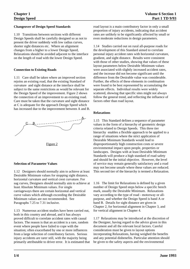
Connection to Existing Roads
1.11 Care shall be taken where an improved sectionrejoins an existing road, that the existing Standard ofcurvature and sight distance at the interface shall besubject to the same restrictions as would be relevant fothe Design Speed of the improvement. Figure 2 showsthe connection of an improvement to an existing road.Care must be taken that the curvature and sight distancat C is adequate for the approach Design Speed whichhas increased due to the improvement between A and
Figure 2
Selection of Parameter Values
1.12 Designers should normally aim to achieve at leasDesirable Minimum values for stopping sight distance,horizontal curvature and vertical crest curvature. Forsag curves, Designers should normally aim to achieve least Absolute Minimum values. For singlecarriageways there are certain horizontal and verticalcurve values which although exceeding the DesirableMinimum values are not recommended. SeeParagraphs 7.25 to 7.31 inclusive.
1.13 Numerous accident studies have been carried ouboth in this country and abroad, and it has alwaysproved difficult to correlate accident rates with causalfactors. The reason is that an accident is a rare, randomevent where people have failed to cope with thesituation; often exacerbated by one or more influencesfrom a large selection of contributory factors. Seriousinjury accidents are rarer still, with the majority beingprimarily attributable to driver error. It is estimated that
roprraev
1.thpegrwlawandiFwsescfofa
R
1.vacrhiraDdienlaSanofmT
1.numvapubaCfo
1.thdocoinanbe
ELECTRONIC COPY - NOT
PAPER COPIES OF THIS ELECTR1/4
r
e
B.
t
at
t,
ad layout is a main contributory factor in only a smalloportion of injury accidents, indicating that accidenttes are unlikely to be significantly affected by small oren moderate reductions in design parameters.
14 Studies carried out on rural all-purpose roads fore development of this Standard aimed to correlatersonal injury accident rates with horizontal curvature,adient, and sight distance. Results were consistentith those of other studies, showing that values of theseyout parameters below Desirable Minimum valuesere associated with slightly increased accident rates,d the increase did not become significant until the
fference from the Desirable value was considerable. urther, the effects of these elements in combinationere found to be best represented by accumulating theparate effects. Individual results were widelyattered, showing that specific sites might not alwaysllow the general trend, and reflecting the influence ofctors other than road layout.
elaxations
15 This Standard defines a sequence of parameterlues in the form of a hierarchy of geometric designiteria related to Design Speeds. This three tiererarchy enables a flexible approach to be applied to ange of situations where the strict application ofesirable Minimum Standards would lead tosproportionately high construction costs or severevironmental impact upon people, properties or
ndscapes. Designs with at least Desirable Minimumtandards will produce a high standard of road safetyd should be the initial objective. However, the level
service may remain generally satisfactory and a roaday not become unsafe where these values are reducehis second tier of the hierarchy is termed a Relaxation
16 The limit for Relaxations is defined by a givenmber of Design Speed steps below a specific bench
ark, usually the Desirable Minimum. Relaxationsry according to the type of road - motorway or all-rpose, and whether the Design Speed is band A ornd B. Details for sight distance are given in
hapter 2, for horizontal alignment in Chapter 3, andr vertical alignment in Chapter 4.
17 Relaxations may be introduced at the discretion oe Designer, having regard to the advice given in thiscument and all the relevant local factors. Carefulnsideration must be given to layout options
corporating Relaxations, having weighed the benefitsd any potential disbenefits. Particular attention should given to the safety aspects and the environmental
FOR USE OUTSIDE THE AGENCY
ONIC DOCUMENT ARE UNCONTROLLED June 1993

Volume 6 Section 1 Chapter 1Part 1 TD 9/93 Design Speed
ing,
gs
iven
all
s
3
t
and/or cost benefits which would result from the use oRelaxations. The consideration process should berecorded. The preferred option should be comparedagainst options that would meet Desirable MinimumStandards.
1.18 A number of layout options might be feasible fora scheme, with each containing Relaxations. ThisStandard gives examples of locations where someoptions can be expected to be safer than others. Forexample, providing Desirable Minimum Stopping SighDistance to a junction, at the expense of less thandesirable values of horizontal or vertical curvature at alocation away from that junction. The Relaxation thenbecomes isolated in that only one feature is belowdesirable value on a given length of road, and thatlength does not contain the complication of a junction.In this manner the accident potential of a constrainedalignment has been minimised by applying layoutdesign principles based upon the knowledge currentlyavailable.
1.19 A list of principles to follow when preparingoptions that include Relaxations is as follows. It isequally a list of factors to be taken into account whenconsidering the merits of options.
1.20 The Designer should consider whether, and towhat degree the site is: 1- isolated from other Relaxations c- isolated from junctions - one where drivers have Desirable Minimum
Stopping Sight Distance - subject to momentary visibility impairment only - one that would affect only a small proportion of
the traffic
- on straightforward geometry readilyunderstandable to drivers
- on a road with no frontage access
- one where traffic speeds would be reducedlocally due to adjacent road geometry (eg uphillsections, approaching roundabouts andmajor/minor junctions where traffic has to giveway or stop, etc), or speed limits
1.21 The Designer should also consider whether thefollowing should be introduced in conjunction with anyRelaxation:
c
1
iaaFa
ELECTRONIC COPY - NOT
June 1993 PAPER COPIES OF THIS ELECTRO
f - accident prevention measures (eg safety fencincreased skidding resistance etc.)
- Warning signs and road markings to alert thedriver to the layout ahead.
1.22 The Designer should have regard to the trafficflows carried by the link. High flows may carry agreater risk of queues & standing traffic approachinjunctions in the peak period. Conversely lower flow
t might encourage higher speeds.
1.23 Values for sight distance, horizontal curvatureand vertical curvature shall not be less than those gin Table 3 for 50kph Design Speed.
1.24 Only stopping sight sistance, horizontalcurvature, vertical curvature, and superelevation sh
be subject to Relaxations. Stopping sight distanceRelaxations of up to 1 Design Speed step below
Desirable Minimum may be coincident with horizontal
below Desirable Minimum. All other combinations ofRelaxations are not permitted and shall be treated aDepartures.
overtaking sight distance parameters given in Table
.26 The Relaxations below Desirable Minimum instopping sight distance and vertical curvature for cres
urves and Absolute Minimum for sag curves describedin Paragraphs 2.8 to 2.13 inclusive and 4.9 to 4.17
urvature Relaxations of up to 1 design Speed step
.25 Relaxations are not permitted for either of the
nclusive are NOT permitted on the immediatepproaches to junctions, because the majority ofccidents occur in the vicinity of junctions. or the purposes of this Standard the immediatepproaches to a junction shall be:
a. For at grade major/minor junctionswithout diverge and merge tapers, those lengthsof carriageway on the minor roads between apoint 1.5 times the Desirable Minimum StoppingSight Distance upstream of the Stop line or GiveWay line and the Stop line or Give Way lineitself, and those lengths of carriageway on themainline between a point 1.5 times the DesirableMinimum Stopping Sight Distance from thecentre line of the minor road and the centre lineitself.
b. For roundabouts, those lengths ofcarriageway on the approach to the roundaboutbetween a 1.5 times the Desirable MinimumStopping Sight Distance from the Give Way lineand the Give Way line itself.
FOR USE OUTSIDE THE AGENCY
NIC DOCUMENT ARE UNCONTROLLED 1/5
Chapter 1 Volume 6 Section 1Design Speed Part 1 TD 9/93
c. For diverges, that length of carriagewayfrom a point 1.5 times the Desirable MinimumStopping Sight Distance upstream of the start ofthe diverge taper to the back of the diverge nose.
d. For merges, that length of carriagewayfrom a point 1.5 times the Desirable MinimumStopping Sight Distance upstream of the back ofthe merge nose to the end of the merge taper.
Departures
1.27 In situations of exceptional difficulty whichcannot be overcome by Relaxations, it may be possibleto overcome them by adoption of Departures, the thirdtier of the hierarchy. Proposals to adopt Departuresfrom Standard must be submitted to the OverseeingDepartment for approval before incorporation into adesign layout to ensure that safety is not significantlyreduced.
1.28 Where a scheme will create more than 2km ofWS2 road (Categories 3B & 4, Table 4) then theapproval of the Overseeing Department is required.
ELECTRONIC COPY - NOT FOR USE OUTSIDE THE AGENCY
PAPER COPIES OF THIS ELECTRONIC DOCUMENT ARE UNCONTROLLED June 19931/6

Volume 6 Section 1 Chapter 2Part 1 TD 9/93 Sight Distance
2. SIGHT DISTANCE
al
Envelope of Visibility
2
1
2
1
Stopping Sight Distance
2.1 Table 3 shows the stopping sight distance (SSD)appropriate for each Design Speed.
2.2 Stopping sight distance shall be measured from minimum driver's eye height of between 1.05m and2.00m, to an object height of between 0.26m and 2.00mboth above the road surface, as shown in Figure 3. Itshall be checked in both the horizontal and verticalplane, between any two points in the centre of the laneon the inside of the curve (for each carriageway in thecase of dual carriageways).
Figure 3 Measurement of Stopping Sight Distance d
Full Overtaking Sight Distance
2.3 Table 3, shows for each Design Speed the FullOvertaking Sight Distance (FOSD) required forovertaking vehicles using the opposing traffic lane onsingle carriageway roads. Sufficient visibility forovertaking shall be provided on as much of the road aspossible, especially where daily traffic flows areexpected to approach the maximum design flows.
2.4 FOSD shall be available between points 1.05mand 2.00m above the centre of the carriageway asshown in Figure 4, and shall be checked in both thehorizontal and vertical planes.
2.5 FOSD is considerably greater than stopping sighdistance, and can normally only be economicallyprovided in relatively flat terrain where the combinationof vertical and horizontal alignment permits the design
C
2sidreince
oinorerohbinath(S
O
fu
ELECTRONIC COPY - NO
June 1993 PAPER COPIES OF THIS ELECT
of a flat and relatively straight road alignment.
Envelope of Visibility
.0m
1.05m
2.0m
.05ma
esign considerations regarding the coordinated design
2.7 Care shall be taken to ensure that no substantifixed obstructions obstruct the sightlines including road
t objects such as lamp columns, sign supports, or slimfootbridge supports of width 550mm or under can beignored. Similarly, the effect of short intermittentobstructions, such as bridge parapets of minor roads
under, can be ignored. Lay-bys should, wherever
Figure 4 Measurement of FOSD
oordinated Design of Single Carriageways:
.6 It will frequently be more economic to design aingle carriageway road so as to provide clearlyentifiable Overtaking Sections with FOSD inlatively level areas, with climbing lanes at hills,terspersed with Non-overtaking Sections where
onstraints on the alignment would result in high cost ornvironmental implications. The detailed Standards and
f such links are given in Chapter 6 to Chapter 8clusive. Designs which provide the driver withbvious lengths for overtaking have been found toduce the frequency of serious accidents occurring onads with continuous large radius curves. On the other
and, in some conditions in flat topography speeds maye somewhat reduced. There is therefore always anherent economic trade-off between the constructionnd environmental costs of alternative alignments andeir user benefits, which shall be tested by COBAcotland - NESA).
bstructions to Sight Distance
rniture such as traffic signs. However, isolated slim
possible, be sited on straights or on the outside ofcurves, where stopped vehicles will not obstructsightlines.
T FOR USE OUTSIDE THE AGENCY
RONIC DOCUMENT ARE UNCONTROLLED 2/1

Chapter 2 Volume 6 Section 1Sight Distance Part 1 TD 9/93
.9, be
,s
ded
s,edr
ht
d
Relaxations
2.8 In the circumstances described in Paragraphs 1to 1.26, Relaxations below the Desirable MinimumStopping Sight Distance values may be made at thediscretion of the Designer. The number of DesignSpeed steps permitted below the Desirable Minimumare normally as follows:
motorways band A 1 stepmotorways band B 2 stepsall-purpose band A 2 stepsall-purpose band B 3 steps
However, in the circumstances listed in Paragraphs 22.10, 2.11, and 2.12, the scope for Relaxations shallextended or reduced as described.
2.9 For all band A roads where the stopping sightdistance is reduced by bridge piers, bridge abutmentslighting columns, supports for gantries and traffic signin the verge or central reserve which form momentaryobstructions, the scope for Relaxations may be extenby 1 Design Speed step.
2.10 Long bridge parapets or safety fences or safetybarriers on horizontal curves may obscure stoppingsight distance to the 0.26m object height, although theappropriate sight distance to the tops of other vehiclerepresented by the 1.05m object height, will be obtainabove the parapet or safety fence or safety barrier. Foband A roads where the appropriate stopping sightdistance to the high object is available in this way, thescope for Relaxation of stopping sight distance for siglines passing in front of the obstruction to the 0.26mobject height may be extended by one Design Speedstep.
2.11 On or near the bottom of long grades on dualcarriageways steeper than 3% and longer than 1.5kmthe scope for Relaxations shall be reduced by 1 DesignSpeed step. Conversely, at or near the top of upgradients on single carriageways steeper than 4% anlonger than 1.5 km, the scope for Relaxation may beextended by 1 step due to reduced speeds uphill.
2.12 The scope for Relaxations shall be reduced by 1Design Speed step immediately following anOvertaking Section on single carriageway roads (seeParagraphs 7.5 to 7.16).
ELECTRONIC COPY - NO
PAPER COPIES OF THIS ELECT2/2
.15
2.13 Relaxations below Desirable Minimum are notpermitted on the immediate approaches to junctions asdefined in Paragraph 1.26.
T FOR USE OUTSIDE THE AGENCY
RONIC DOCUMENT ARE UNCONTROLLED June 1993

Volume 6 Section 1 Chapter 3Part 1 TD 9/93 Horizontal Alignment
3. HORIZONTAL ALIGNMENT
7)
%
Road Camber Su
3.1 On sections of road with radii greater than thatshown in Table 3, (Minimum R without elimination ofadverse camber & transitions), (ie V²/R < 5) thecrossfall or camber should be 2.5% from the centre ofsingle carriageways, or from the central reserve of dualcarriageways to the outer channels. At junctions otherthan roundabouts, the cross-section of the major roadshall be retained across the junction, and the side roadgraded into the channel line of the major road. Onhorizontal curves, adverse camber shall be replaced byfavourable crossfall of 2.5% when the radius is less thanthat shown in Table 3, (Minimum R without eliminationof adverse camber & transitions), (ie V²/R > 5). However, it will frequently be necessary to eliminateadverse camber on larger radii for aesthetic or drainagereasons.
ELECTRONIC COPY - NOT
June 1993 PAPER COPIES OF THIS ELECTR
.
perelevation
3.2 On radii less than those shown in Table 3,(Minimum R with superelevation of 5%), (ie. V²/r >superelevation shall be provided, such that:
V²S= ))))))
2.828 x R
Where :V = Design Speed kph
R = Radius of Curve m.
S = Superelevation %.
In rural areas superelevation shall not exceed 7
In urban areas with at-grade junctions and sideaccesses, superelevation shall be limited to 5%
50 kp
h
60 kp
h
70 kp
h85
kph
100 k
ph
120 k
ph2.5%
FAVOURABLECROSSFALL
Superelevation >7% only permissable onexisting roads or loops at interchanges
0.04
0.06
0.08
0.10
0.12 RE
SID
UA
L S
IDE
WA
YS
FO
RC
E T
AK
EN
BY
RO
AD
SU
RF
AC
E
200 400 600 800 1000 1200 1400 1600 1800 2000
RADIUS IN METRES
2
3
4
5
6
7
8
9
10
SU
PE
RE
LEV
AT
ION
%
5%DESIRABLEMAXIMUM
SUPERELEVATION
7%ABSOLUTEMAXIMUM
SUPERELEVATION
Figure 5 Superelevation of Curves
FOR USE OUTSIDE THE AGENCY
ONIC DOCUMENT ARE UNCONTROLLED 3/1

Chapter 3 Volume 6 Section 1Horizontal Alignment Part 1 TD 9/93
thefns
mum
rse of thes
er at
latort
et.
s,
f
Figure 5 shows the appropriate superelevation for therange of Design Speeds. Sharper radii than the DesirableMinimum shown in Table 3 result in steep crossfallswhich should be avoided if possible. It is essential tomaintain adequate skidding resistance and good drainageat all superelevations in accordance with the OverseeingDepartment's current criteria.
Desirable Minimum Radius
3.3 The Desirable Minimum radii, corresponding withsuperelevation of 5% and radii below Desirable Minimumwith superelevation of 7% are shown in Table 3 (ie V²/R> 14 Desirable, 20 Absolute Maximum).
Relaxations
3.4 In the circumstances described in Paragraphs 1.161.26, Relaxations below the Desirable Minimum valuesmay be made at the discretion of the Designer. Thenumber of Design Speed steps permitted below theDesirable Minimum are normally as follows:-
motorways band A 2 stepmotorways band B 3 stepsall-purpose band A 3 stepsall-purpose band B 4 steps
However, for all roads in Design Speed band B in thecircumstances listed in Paragraphs 3.5 and 3.6, the scopefor Relaxations shall be extended or reduced as describe
3.5 On or near the bottom of long grades on dualcarriageways steeper than 3% and longer than 1.5km thescope for Relaxations shall be reduced by 1 Design Speedstep. Conversely, at or near the top of up gradients onsingle carriageways steeper than 4% and longer than 1.5km, the scope for Relaxations may be extended by 1 stepdue to reduced speeds uphill.
3.6 The scope for Relaxations shall be reduced by 1Design Speed step immediately following an OvertakingSection on single carriageway roads (see Paragraphs 7.57.16).
A
3caoactcc
lwHrsIavcsb
A
w
W
3tsw
3a
ELECTRONIC COPY - NOT FO
PAPER COPIES OF THIS ELECTRON3/2
n
smoother edge profile should be provided by reducingvariation in grade of the edge profile to a maximum o0.5% where feasible, ie where local drainage conditio
permit, and care should be taken to ensure that a mini
to
3.8 Progressive superelevation or removal of advecamber shall be achieved over or within the length
d. transition curve from the arc end. On existing road
introduced on the approach straight and the remaindthe beginning of the curve.
to
ppearance and Drainage
.7 Superelevation shall not be introduced, nor adverseamber removed, so gradually as to create large almost freas of carriageway, nor so sharply as to cause discomfr to kink the edges of the carriageway. A satisfactoryppearance can usually be achieved by ensuring that thearriageway edge profile does not vary in grade by morehan about 1% from that of the line about which thearriageway is pivoted, and by ample smoothing of allhanges in edge profile. In general on motorways, a
ongitudinal gradient of at least 0.5% is maintainedherever superelevation is to be applied or reversed. owever, in some difficult areas even the above
equirements can lead to drainage problems, eg where thuperelevation is applied against the longitudinal gradient may be necessary to either modify the horizontallignment to move the superelevation area, increase theariation in grade of the edge profile, or apply a rollingrown. Areas susceptible to such drainage problemshould be identified at an early stage in the design procesefore the horizontal alignment is fixed.
pplication of Superelevation
ithout transitions, between ½ and b of the cant shall be
idening on Curves
.9 Widening of curves on links and on the main linehrough junctions is required for carriageways of less thantandard width and for low radius curves of standardidth to allow for the swept path of long vehicles.
.10 For Carriageways of Standard Width, (7.3m, 11m,nd 14.6m for 2, 3 or 4 lanes respectively), an increase o
0.3m per lane shall be allowed when the radius is betwee90m and 150m. Two lane roads of width greater than7.9m require no additional widening.
R USE OUTSIDE THE AGENCY
IC DOCUMENT ARE UNCONTROLLED June 1993

Volume 6 Section 1 Chapter 3Part 1 TD 9/93 Horizontal Alignment
p
3.11 For Carriageways less than the Standard Widths,widening shall be:
0.6m per lane where the radius is between 90m an150m subject to maximum carriageway widths of7.9m, 11.9m and 15.8m (for 2, 3 and 4 lanesrespectively).
0.5m per lane where the radius is between 150m a300m, subject to a maximum width not greater thanthe standard width in Paragraph 3.10 above.
0.3m per lane, where the radius is between 300mand 400m subject to a maximum width not greaterthan the standard width in Paragraph 3.10 above.
3.12 Radii less than 90m on the mainline are Departurefrom standard. For these and all other junction elementswidening should be in accordance with TA 20 (DMRB6.2).
3.13 The extra width should be applied uniformly alongthe transition curve. In the improvement of existingcurves the widening should generally be made on theinside of curves.
Lane Width Reductions at Pinch Points:
3.14 At points of particular difficulty on new dualcarriageways, where full lane widths cannot be achieved,reduction from 3.65m to 3.50m is permitted provided thatthe radius of curvature exceeds 1000m. Points where sua relaxation are likely to be most applicable are around thurban fringe, and at sites with difficult topography or inhistoric or conservation areas. This relaxation shall notapply on new single carriageway roads.
Transitions
3.15 Transition curves shall be provided on curves theradius of which are less than that shown in Table 3,Minimum R without elimination of adverse camber &transitions.
f
W
LVq
R
qdtan
3eoehttm
T
3cwtFvDscbDWbc
ELECTRONIC COPY - NOT FO
June 1993 PAPER COPIES OF THIS ELECTRON
3.16 Length of Curve:The basic transition length shall be derived from the
d
nd
s,
a
che
ormula:V³
L= ))))))))))))
46.7 x q x R
here:
= Length of transition (m) = Design Speed (kph) = Rate of increase of centripetal acceleration (m/sec³)
travelling along curve at constant speed V(kph) = Radius of curve (m)
should normally not exceed 0.3 m/sec³, although inifficult cases, it may be necessary to increase the value u
o 0.6 m/sec³. On bends (sub-Standard curves for theppropriate Design Speed) the length of transition shouldormally be limited to %(24R) metres.
.17 Application of Superelevation: Superelevation orlimination of adverse camber shall generally be appliedn or within the length of the transition curve from the arcnd. The basic transition appropriate to the Design Speedowever will often result in insufficient transition length
o accommodate superelevation turnover, and it willherefore be necessary to provide longer transitions toatch the superelevation design.
he Effect of Sight Distance at Horizontal Curves
.18 Stopping Sight Distance: When the road is in autting, or at bridge crossings, it will be necessary toiden verges or increase bridge clearances to ensure that
he appropriate stopping sight distance is not obstructed. igure 6 shows the maximum central offset required witharying horizontal curvature, in order to maintain theesign Speed related stopping sight distances. It can beeen that extensive widening of verges and structures, orentral reserves with safety fence or safety barriers, woulde required to maintain Desirable Stopping Sightistances on horizontal radii below Desirable Minimum. here a road is on embankment, however, visibility will
e available across the embankment slope, and in suchases it is environmentally desirable to permit beneficial
usage of the land by granting a licence to adjoininglandowners under Section 142, Highways Act, 1980. (Scotland: Section 50, Roads Scotland Act 1984.)
R USE OUTSIDE THE AGENCY
IC DOCUMENT ARE UNCONTROLLED 3/3

Chapter 3 Volume 6 Section 1Horizontal Alignment Part 1 TD 9/93
3/4
CE
NT
RA
L O
FF
SE
T X
m
80 127
180
255
380
510
720
1020
1440
RADIUS, TWODESIGN SPEEDSTEPS BELOWDESIRABLEMINIMUM
V2
R= 28.28
Not applicable forCategory A designs.Use One Step belowDesirable Minimum SSD forCategory B designs.
SSD
RADIUS RmCEMTRAL OFFSET Xm
The values shown are the maxima and apply whereSSD > curve length. Land for visibility should bechecked from the plans.
RADIUS, ONEDESIGN SPEEDSTEPS BELOWDESIRABLEMINIMUM
V2
R= 28.28
V2
R= 28.28DESIRABLE
MIN R
30
25
20
15
10
5
2040
Standard Rural3.5m Verge
2000150010005000
50 k
ph80
kph
70 k
ph
85 k
ph
100
kph
120
kph
RADIUS Rm
Figure 6 Verge Widening for Desirable Minimum Stopping Sight Distance
ELECTRONIC COPY - NOT FOR USE OUTSIDE THE AGENCY
PAPER COPIES OF THIS ELECTRONIC DOCUMENT ARE UNCONTROLLED June 1993

Volume 6 Section 1 Chapter 3Part 1 TD 9/93 Horizontal Alignment
3.19 Full Overtaking Sight Distance: Figure 7 shows themaximum central offset required with varying horizontalcurvature, in order to maintain the Design Speed relatedFOSD's. It can be seen that the higher requirements ofFOSD result in extensive widening of verges for all butrelatively straight sections of road, and in such cases it isenvironmentally desirable to permit beneficial usage of theland by granting a licence to adjoining landowners underSection 142, Highways Act, 1980. (Scotland: Section 50,Roads Scotland Act 1984).
< 1
0.65
m M
ax V
erge
Wid
th >
CENTRALOFFSET Xm
FOSD
RADIUS
The values shown are maxima and apply where FOSD > curve length. Land forvisibility should be checked from the plans.
360
510
720
1020
1440
2040
2880
4080
5760
50 kph
60 kph
70 kph
85 kph
100 kph
30
25
20
15
10
5
0
1000 2000 3000 10004000 5000 6000
RADIUS Rm
CE
NT
RA
L O
FF
SE
T X
m
V
R
2
7.07
5.0
3.53
2.5
1.76
1.25
MAXV
R
2
Standard Rural3.5m Verge
FOR O/TAKING SECTION
Figure 7 Verge Widening for FOSD
ELECTRONIC COPY - NOT FOR USE OUTSIDE THE AGENCY
June 1993 PAPER COPIES OF THIS ELECTRONIC DOCUMENT ARE UNCONTROLLED 3/5
Volume 6 Section 1 Chapter 4Part 1 TD 9/93 Vertical Alignment
4. VERTICAL ALIGNMENT
ge
e
ass a20
rt. Athe road
sly.
e thatingSpeed
d to
f
Gradients Ve
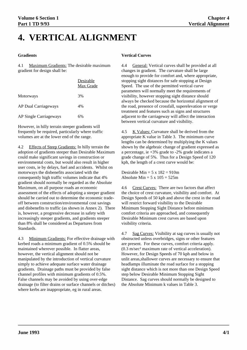
4.1 Maximum Gradients: The desirable maximum 4gradient for design shall be:
Desirable stoMax Grade Sp
Motorways 3% vi
AP Dual Carriageways 4% t
AP Single Carriageways 6%
However, in hilly terrain steeper gradients willfrequently be required, particularly where trafficvolumes are at the lower end of the range.
4.2 Effects of Steep Gradients: In hilly terrain the shadoption of gradients steeper than Desirable Maximumcould make significant savings in construction orenvironmental costs, but would also result in higheruser costs, ie by delays, fuel and accidents. Whilst onmotorways the disbenefits associated with theconsequently high traffic volumes indicate that 4%gradient should normally be regarded as the AbsoluteMaximum, on all purpose roads an economicassessment of the effects of adopting a steeper gradientshould be carried out to determine the economic trade-off between construction/environmental cost savingsand disbenefits to traffic (as shown in Annex 2). Thereis, however, a progressive decrease in safety withincreasingly steeper gradients, and gradients steeperthan 8% shall be considered as Departures fromStandards.
4.3 Minimum Gradients: For effective drainage with okerbed roads a minimum gradient of 0.5% should bemaintained wherever possible. In flatter areas,however, the vertical alignment should not bemanipulated by the introduction of vertical curvaturesimply to achieve adequate surface water drainagegradients. Drainage paths must be provided by falsechannel profiles with minimum gradients of 0.5%. False channels may be avoided by using over-edgedrainage (to filter drains or surface channels or ditches)where kerbs are inappropriate, eg in rural areas.
en
pa
alw
tre
be
len
4.7
ELECTRONIC COPY - NO
June 1993 PAPER COPIES OF THIS ELECT
rtical Curves
.4 General: Vertical curves shall be provided at allchanges in gradient. The curvature shall be large
pping sight distances for safe stopping at Designeed. The use of the permitted vertical curve
sibility, however stopping sight distance should
he road, presence of crossfall, superelevation or ver
adjacent to the carriageway will affect the interaction
4.5 K Values: Curvature shall be derived from theappropriate K value in Table 3. The minimum curv
own by the algebraic change of gradient expressed a percentage, ie +3% grade to -2% grade indicate
grade change of 5%. Thus for a Design Speed of 1kph, the length of a crest curve would be:
Desirable Min = 5 x 182 = 910mAbsolute Min = 5 x 105 = 525m
4.6 Crest Curves: There are two factors that affectthe choice of crest curvature, visibility and comfo
Design Speeds of 50 kph and above the crest in twill restrict forward visibility to the DesirableMinimum Stopping Sight Distance before minimumcomfort criteria are approached, and consequentlyDesirable Minimum crest curves are based upon
visibility criteria.
bstructed unless overbridges, signs or other featureare present. For these curves, comfort criteria app(0.3 m/sec² maximum rate of vertical acceleration).However, for Design Speeds of 70 kph and below inunlit areas,shallower curves are necessary to ensur
headlamps illuminate the road surface for a stoppsight distance which is not more than one Design
step below Desirable Minimum Stopping SightDistance. Sag curves should normally be designethe Absolute Minimum k values in Table 3.
ough to provide for comfort and, where appropriate,
rameters will normally meet the requirements of
ays be checked because the horizontal alignment o
atment and features such as signs and structures
tween vertical curvature and visibility.
gths can be determined by multiplying the K values
Sag Curves: Visibility at sag curves is usually not
T FOR USE OUTSIDE THE AGENCY
RONIC DOCUMENT ARE UNCONTROLLED 4/1

Chapter 4 Volume 6 Section 1Vertical Alignment Part 1 TD 9/93
a
s
e
5or
4.8 Grass Verges Where, at crests, the sight linecrosses the verge, consideration shall be given to thedesign of a lower verge profile in order to allow for anoverall height of grass of 0.5m.
Relaxations
4.9 Crest curves In the circumstances described inParagraphs 1.15 to 1.26, Relaxations below theDesirable Minimum values may be made at thediscretion of the Designer. The number of DesignSpeed steps permitted below the Desirable Minimumare normally as follows:
motorways band A 1 stepmotorways band B 2 stepsall-purpose band A 2 stepsall-purpose band B 3 steps
However, in the circumstances listed in Paragraphs4.10, 4.11 and 4.12 the scope for Relaxations shall bextended or reduced as described.
4.10 At or near the top of up gradients on singlecarriageways steeper than 4% and longer than 1.5 kmthe scope for Relaxations may be extended by 1 stepdue to reduced speeds uphill.
4.11 The scope for Relaxations shall be reduced by 1Design Speed step immediately following anOvertaking Section on single carriageway roads (seeParagraphs 7.5 to 7.16).
4.12 For band A roads when the crest curve is withinstraight section the scope for Relaxations may beextended by 1 Design Speed step.
4.13 Relaxations below Desirable Minimum are notpermitted on the immediate approaches to junctions a
ELECTRONIC COPY - NO
PAPER COPIES OF THIS ELECTR4/2
defined in Paragraph 1.26.
4.14 Sag curves In the circumstances described inParagraphs 1.15 to 1.26, Relaxations below the
Absolute Minimum values may be made at thediscretion of the Designer. The number of Design
e
,
Speed steps permitted below the absolute minimum arnormally as follows:
motorways none all-purpose all others 1 stepall-purpose 50B, 60B, 70B 2 steps
However, in the circumstances listed in Paragraphs 4.1and 4.16, the scope for Relaxations shall be extended reduced as described.
4.15 For Design Speeds of 70kph and less where theroad is illuminated, the scope for Relaxations may beextended by one Design Speed step.
4.16 For roads in Design Speed bands 50B, 60B and70B the scope for Relaxations shall be reduced by 1Design Speed step immediately following anOvertaking Section on single carriageway roads (seeParagraphs 7.5 to 7.16).
4.17 Relaxations below Desirable Minimum are notpermitted on the immediate approaches to junctions asdefined in Paragraph 1.26.
T FOR USE OUTSIDE THE AGENCY
ONIC DOCUMENT ARE UNCONTROLLED June 1993

Volume 6 Section 1Part 1 TD 9/93 Amendment No 1
February 2002 5/1
Chapter 5Climbing Lanes
5. CLIMBING LANES
INTRODUCTION
5.1 Scope: This chapter outlines the design principlesand other factors which should be considered bydesigners for the introduction of climbing lanes into anexisting carriageway or new build situation. Theprocess of design is described below together with anapproach to assessing the viability of the climbing lane.
5.2 General: This chapter replaces the existingChapter 5 of TD 9/93. It provides clarification and is anextension of layout advice given in the previousdocument. In particular, amended advice is given forthe use of climbing lanes on single carriageways, whichhas been revised following a safety review into theoperation of climbing lanes. Other major changes are asfollows:
• The assessment procedures and definitions havebeen updated and extended.
• Annex B (Economic Implications of SteepGradients on Single Carriageways) and Annex C(Climbing Lanes for All Purpose DualCarriageways and Motorways EconomicAppraisal Method) in the previous standard havebeen superseded by the assessment procedurescontained in DMRB Volumes 13 and 14.
• The presentation has been improved with newtables and additional figures.
• Additional layouts illustrating the use ofclimbing lanes commencing and terminating atroundabouts are included.
• Advice on road markings has been clarified andextended (see Chapter 5 of Traffic Signs Manualfor guidance on road markings).
5.3 Implementation: This chapter should be used forthe design, assessment and construction of all trunkroad schemes including improvements to the existingtrunk road network. The exceptions are schemescurrently being prepared where application of thischapter would result in significant delays or costs.
5.4 Appraisal: This chapter highlights the potentialimpacts of climbing lanes in relation to the fiveGovernment objectives for transport (see paragraph5.6).
SCHEME APPRAISAL
5.5 Introduction: In considering the need for aclimbing lane, assessment, consultation and designmust be an iterative process and should consider theappropriateness and significance of impacts measuredagainst the scheme objectives. The design should takeaccount of Standards, the Traffic Signs Regulations andGeneral Directions, the Traffic Signs Manual and otherDTLR publications.
5.6 Particular emphasis should be attached to themulti-modal appraisal objectives listed below, thatshould be carried out in accordance with the overseeingorganisation’s current procedures and to measures thatbenefit local communities, whether by improving safetyand accessibility, or enhancing the environment.
• Safety (reduction in accidents).
• Environment (reduction in environmentalintrusion, driver frustration, noise and airpollution).
• Economy (reduction in travel times, vehicleoperating costs and journey time reliability).
• Accessibility (climbing lanes are unlikely to haveany measurable impacts).
• Transport Integration (climbing lanes are unlikelyto have any measurable impacts).
5.7 In preparing a design for a climbing lane section,the following ‘scheme development’ procedures shouldbe adopted:
1. Identify the problem.
2. Prepare the scheme brief.
3. Assess the impacts within the frameworkprovided by the five transport objectives ofSafety, Economy, Environmental Impact,Integration and Accessibility.
4. Consider requirements for value engineering andscheme appraisal.
In situations where a climbing lane is added to anexisting carriageway, data should be collected and“Before” surveys carried out if necessary.

Volume 6 Section 1Part 1 TD 9/93 Amendment No 1
February 20025/2
Chapter 5Climbing Lanes
5.8 Definitions: For the purposes of this document, aclimbing lane is defined as an additional lane added to asingle or dual carriageway in order to improve capacityand/or safety because of the presence of the steepgradient. The steep gradient is the primary reason foradding a lane. A climbing lane may be inserted into thecarriageway by means of entry and exit tapers. In thesecases the climbing lane should be a continuation of thenear side lane with widening to the right so thatovertaking traffic has to merge into the slower movingtraffic at the termination points. Alternatively, aclimbing lane may be inserted into a carriageway at aroundabout, simplifying the layout of a change incarriageway width.
5.9 On single carriageways, a climbing lane can beconsidered if it can be justified (see paras 5.11 to 5.27)on hills with gradients greater than 2% and longer than500m.
5.10 On dual carriageways, gradients of 3% over adistance of 500m would be expected to be the minimumthat would justify an additional lane.
5.11 Assessment of Impacts: The provision of anadditional lane on an uphill section of a single or dualcarriageway should provide benefits to travellers bydiminishing delays caused by slow-moving traffic. Theeffect of adding a lane is two-fold; some traffic is ableto move over to a faster lane, thereby gaining asignificant speed advantage, and the consequentreduction of traffic in the left hand lane could enablespeeds to increase in these slower lanes. Gradients canbe pinch points, particularly on dual carriageways,where congestion starts when traffic flows approachcapacity. On roads where design year flows are high theeconomic benefits can be substantial. On singlecarriageways, the economic benefits are likely to be lesssubstantial but the climbing lane can also be viewed asa safety measure, by creating a safer overtakingenvironment and by reducing driver frustration.
5.12 Economy: The procedure for economic appraisalshall be based upon the guidance provided in DMRBVolume 13 (Economic Assessment of Road Schemes,Part 5, Paragraph 2.15 for single carriageways andParagraph 3.13 for dual carriageways). This provides ameans within COBA of modelling the economicbenefits accruing through the introduction of a sectionof climbing lane. The Do Something (climbing lane)can be measured against the Do Nothing (no climbinglane) as well as an assessment of alternative climbinglane length and slope configurations. In Scotland NESA(DMRB Volume 15) is used in place of COBA.Guidance on climbing lanes is given in DMRB Volume
15, Part 7, Paragraphs 2.11 and 2.12 for singlecarriageways and Paragraph 3.11 for dual carriageways.
5.13 Figure 5/1 provides a preliminary indication ofwhether a climbing lane is likely to be economicallyjustified at single carriageway sites using COBA11.The proportion of HGVs is fixed at 10% whilst a rangeof values have been tested for the following parameters:
• Traffic flow (AADT)
• Height risen (metres)
5.14 A negative NPV (Net Present Value) means thatthe scheme cannot be justified on economic grounds.The diagram is not sensitive enough to show thechanges in NPV due to different percentage HGVs andthis can only be recognised in project-specificappraisals. It is also worth noting that in economicterms, HGVs do not benefit much from the provision ofa climbing lane on a single carriageway road. It is thelight vehicles that benefit most from the increasedovertaking opportunities provided and increased speed.
5.15 The height risen (H) and length (L) shall becalculated between two standard points on a hill asdefined in Figure 5/2 and Figure 5/3 for both single anddual carriageways. Benefits accrued should bemeasured against the estimated cost of the climbinglane which will be scheme specific. On typical ruralterrain without any high cost elements, the cost may bein the order of £0.35M per km in 1998 prices.
5.16 Where there are high cost elements involved suchas environmental effects, structures, or significantearthworks, (which would invalidate the average costassumptions of Figure 5/1), it may be uneconomic orundesirable to make full provision. In suchcircumstances, consideration may be given to otheroptions which may require a Departure from standard,as an alternative to omitting the climbing lanealtogether.
5.17 An analysis using the QUADRO program(DMRB 14) should also be run to estimate user costsduring construction if the lane is added to an existingroad. Future maintenance costs and delays to usersduring maintenance should also be considered.
5.18 Safety: Climbing lanes help to relieve driverfrustration and provide a safer overtaking environment.This is particularly the case for climbing lanes on singlecarriageway roads.

Volume 6 Section 1Part 1 TD 9/93 Amendment No 1
February 2002 5/3
Chapter 5Climbing Lanes
5.19 Factors which help to create a safer roadenvironment include the avoidance of sharp bends,poorly marked and located junctions, short climbingsection lengths and short and unusual entry or exittapers. In particular, the exit taper should not be locatedin the vicinity of junctions or sharp bends.
5.20 Climbing lanes on trunk roads tend to be saferthan climbing lanes on non-trunk roads because of theroad geometry. A survey at 83 single carriagewayclimbing lane sites showed that the average accidentrate at trunk road sites in 1998 was 0.119 PIAs permill.veh.km (climbing lane and both tapers) comparedwith 0.240 on non-trunk roads. These accident ratescompare with the COBA national rates of 0.144 (linkonly) and 0.260 (combined link and junction) forModern S2 roads with a prevailing speed limit of 50 or60 mph.
5.21 As a guide, the presence of a climbing lane on asingle carriageway road can be expected to reduce theaccident rate by about 25%. A scheme-specific estimateshould be made of the accident saving, which mayinclude overtaking accidents both before and after aswell as on the climbing lane section if it forms part ofan overall overtaking strategy. The estimate of accidentsaving should be made on the basis of local accidentdata and records before being incorporated into thesafety appraisal.
5.22 Environment: Climbing Lanes can have animpact on the environment in a number of ways andenvironmental issues need to be considered as anintegral part of the design and appraisal process. Thelikely impact on, for example, wildlife will be neutralor negative if additional land-take is necessary.However the impact may be positive if the increasedgradient with diminished earthworks leads to less land-take and reduced visual intrusion, particularly on dualcarriageways.
5.23 In addition, and of particular relevance toclimbing lanes, driver frustration should also form partof the environmental appraisal process for singlecarriageway roads (DMRB Volume 11, Section 3, Part9, Paragraphs 4.1 to 4.9). Whilst useful engineeringdata relating to driver frustration is scarce, carefulconsideration should be given to the provision ofadequate overtaking opportunities. In other countries,studies have shown that where drivers are forced tofollow slow moving vehicles for distances up to 8km,some 35% of drivers disobeyed the law and carried outan unsafe overtaking manoeuvre revealing a high levelof driver frustration.
5.24 Integration: The assessment of proposals shouldtake account of all relevant national, regional, strategicand detailed local planning policies including transportpolicies. As with the assessment of accessibility, adesign, which incorporates a climbing lane, should beassessed in accordance with the current recommendedappraisal practice.
5.25 Accessibility: It is considered unlikely that theprovision of a climbing lane would have a significanteffect on the journeys undertaken using non-motorisedtransport where routes run along the carriageway. Theaddition of a climbing lane to single or dualcarriageways could however have a detrimental impactwhere at-grade crossings of all purpose carriageways ismade unusable where heavy traffic flows prevail.Depending on circumstances this may be termed aSignificant Adverse impact under the Accessibilitycriterion. Potential severance effects should be includedin the appraisal along with the viability of maintaining,re-routeing or providing additional measures such asfootbridges etc. in the design process. Climbing lanesmay involve closure of at-grade crossings in ruralsituations with resulting provision of footpathdiversions.
5.26 New designs would be appraised as part of thefull scheme assessment.
5.27 Summary: Due consideration should be taken ofthe total balance of overall benefits and dis-benefits.The designer should in most cases produce an AppraisalSummary Table where the main environmental,economic, and social impacts are reported.

Volume 6 Section 1Part 1 TD 9/93 Amendment No 1
February 20025/4
Chapter 5Climbing Lanes
Figure 5/1: Single Carriageway Climbing Lanes - Economic Justification

Volume 6 Section 1Part 1 TD 9/93 Amendment No 1
February 2002 5/5
Chapter 5Climbing Lanes

Volume 6 Section 1Part 1 TD 9/93 Amendment No 1
February 20025/6
Chapter 5Climbing Lanes
LAYOUT – SINGLE CARRIAGEWAYS
5.28 Climbing Lanes on Wide Single Carriageways:On wide single carriageways (WS2) the normal 2 widelanes can be reduced, so as to provide an additionalclimbing lane within the normal cross-section. Thescheme appraisal is an integral part of the designprocess and should enable climbing lanes to beprovided wherever their use would be of advantage inpermitting slow moving climbing traffic to beovertaken.
5.29 Climbing lanes on WS2 roads however shall notbe used for gradients less than 2% or shorter than500m. In addition, it is important that a driver’sperception of the hill is not distorted by the fact that theadjoining topography is on a different verticalalignment and thus may lead to a false impression ofthe true road gradient (Figure 5/4). Generous visibilityat the crest should not be provided as this could causeabuse of the centre line priority.
Figure 5/4: Conflict with general slope of terrain
5.30 Length of Climbing Lanes: The length ofOvertaking Section should be a minimum of 500m,excluding any sections on gradients less than 2%. Shortclimbing lanes have a higher accident risk that isexacerbated by bends in the road. High accident ratesare associated with average bendiness (irrespective ofclimbing lane length) in excess of 50 degs/km.
5.31 Climbing lane road markings tend to confinedownhill traffic to a single lane, unless there is ampleforward visibility unobstructed by slow-movingvehicles in the climbing lane. It is important therefore,where the length of a climbing lane exceeds about 3km,that some sections are provided with a straight or largeradius right hand curvature (see paragraph 7.13) inorder to provide an Overtaking Section for downhilltraffic, and reduce driver stress (ref DMRB Vol. 11,Section 3, Part 9, Chapter 4).
5.32 Lane Widths: An overall width of 10m(excluding edge strips if provided) shall be divided into3 lanes, the uphill climbing lane being 3.2m wide, theother two being 3.4m each, as shown in Figure 5/5.Offset priority markings shall be provided.
Figure 5/5: Lane Widths
5.33 Hard strips, which enhance visibility and extendthe carriageway width, can improve the safety of theclimbing lane and should be used where possible andwithin economic constraints.
5.34 Layout at Start of Climbing Lane: The full widthof the climbing lane shall be provided at a point S,100m uphill from the 2% point of sag curve, andpreceded by a taper of 1/30 – 1/40, as shown in Figure5/6. The alignment at the commencement of theclimbing lane shall encourage drivers to follow thenearside channel unless overtaking. The taper shallprovide a smooth transition, by utilising the roadcurvature to develop the extra width, wherever possible.
5.35 Climbing lanes may also be inserted directly intothe exit lane of a roundabout where the geometry doesnot allow the use of conventional layout (Figure 5/7).
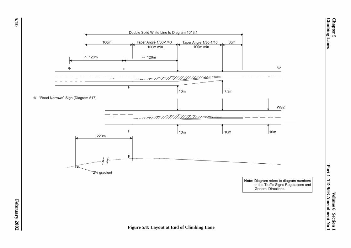
5.36 Layout at End of Climbing Lane: The full widthof the climbing lane should be maintained up or downthe gradient to a point F, 220m beyond the end of the2% point of the crest curve. After point ‘F’ a taper ofbetween 1/30 and 1/40 is provided to narrow thecarriageway width from the offside thereby removingthe extra width that allowed the provision of theclimbing lane (see Figures 5/2 and 5/8).
5.37 The alignment at the end of the climbing laneshall place the onus on the overtaking driver to rejointhe inside lane. The taper shall therefore provide asmooth transition in the same manner as that at the startof the climbing lane. Advance warning signs shall beprovided as shown in Figure 5/8. Care should be takento ensure that the return to a single lane does notcoincide with junctions or sharp curves.
5.38 Consideration should be given to extending thedistance between the 2% point and point ‘F’, the end ofthe full width of the climbing lane, in the followingcircumstances:

Volume 6 Section 1Part 1 TD 9/93 Amendment No 1
February 2002
Chapter 5Climbing Lanes
5/7
• If an existing junction is in the vicinity of theexisting merge taper area and/or where theextension enables traffic to merge more safely.
• If the climbing lane is part of an overall RouteStrategy for Overtaking and that the climbinglane is extended to maximise overtakingopportunities.
• If a high proportion of HGVs, or slow movingvehicles, currently cause problems orsignificantly reduce capacity in the merge taperarea, the merge may be extended where heavyvehicles are picking up speed as the road beginsto descend from the crest of the hill.
5.39 In situations where the climbing lane terminationpoint is extended, greater than 220m beyond the 2%point, the taper arrangement at the end of the climbinglane is the same as that of the climbing lane terminatingat 220m beyond the 2% point (as shown in Figure 5/3).
5.40 The climbing lane may terminate at a roundaboutso that the overtaking lane becomes the right hand entrylane into the roundabout (Figure 5/9).
5.41 Junctions: Careful consideration should be givenwith respect to the location of junctions along thelength of the climbing lane. In new build situationsprovision of junctions within the length of the climbinglane (including the tapers) should be avoided. Inexisting situations priority should be given to a strategyof closure of junctions that occur within the length ofthe climbing lane and re-routeing of accesses and sideroads.
5.42 Signing: Clear signing and road markings at theend of a climbing lane is very important to ensure thevehicles are fully aware of potential “change of lane”movements of vehicles that will be taking place ahead.This is important both from the point of view of safetyand efficient operation of the climbing lane.

Volum
e 6 Section 1P
art 1 TD
9/93 Am
endment N
o 1
February 2002
5/8
Chapter 5
Clim
bing Lanes
Figure 5/6: Layout at Start of Climbing Lane

Volum
e 6 Section 1P
art 1 TD
9/93 Am
endment N
o 1
February 2002
Figure 5/7: Climbing Lane Starts at Roundabout Exit - Single Carriageway
Chapter 5
Clim
bing Lanes
5/9
Volum
e 6 Section 1P
art 1 TD
9/93 Am
endment N
o 1
February 2002 Figure 5/8: Layout at End of Climbing Lane
5/10
Chapter 5
Clim
bing Lanes

Volum
e 6 Section 1P
art 1 TD
9/93 Am
endment N
o 1
February 2002
Figure 5/9: Climbing Lane Ends at Roundabout Entry - Single Carriageway
Chapter 5
Clim
bing Lanes
5/11
Volume 6 Section 1Part 1 TD 9/93 Amendment No 1
February 2002
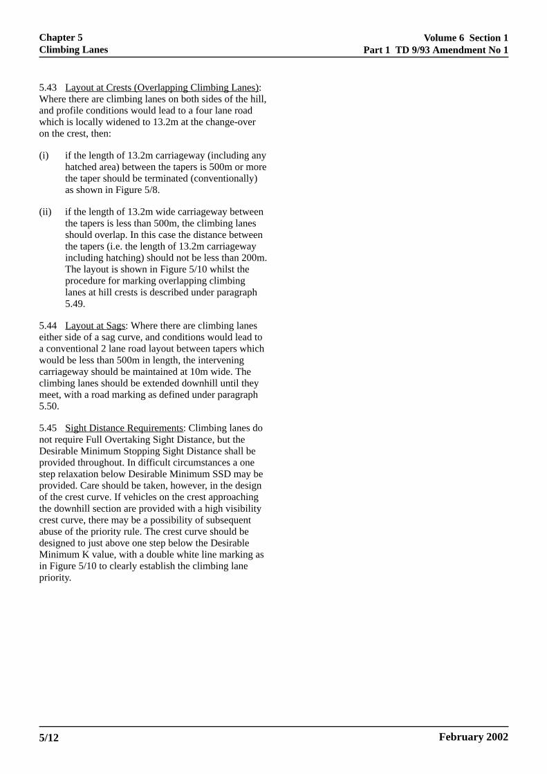
5.43 Layout at Crests (Overlapping Climbing Lanes):Where there are climbing lanes on both sides of the hill,and profile conditions would lead to a four lane roadwhich is locally widened to 13.2m at the change-overon the crest, then:
(i) if the length of 13.2m carriageway (including anyhatched area) between the tapers is 500m or morethe taper should be terminated (conventionally)as shown in Figure 5/8.
(ii) if the length of 13.2m wide carriageway betweenthe tapers is less than 500m, the climbing lanesshould overlap. In this case the distance betweenthe tapers (i.e. the length of 13.2m carriagewayincluding hatching) should not be less than 200m.The layout is shown in Figure 5/10 whilst theprocedure for marking overlapping climbinglanes at hill crests is described under paragraph5.49.
5.44 Layout at Sags: Where there are climbing laneseither side of a sag curve, and conditions would lead toa conventional 2 lane road layout between tapers whichwould be less than 500m in length, the interveningcarriageway should be maintained at 10m wide. Theclimbing lanes should be extended downhill until theymeet, with a road marking as defined under paragraph5.50.
5.45 Sight Distance Requirements: Climbing lanes donot require Full Overtaking Sight Distance, but theDesirable Minimum Stopping Sight Distance shall beprovided throughout. In difficult circumstances a onestep relaxation below Desirable Minimum SSD may beprovided. Care should be taken, however, in the designof the crest curve. If vehicles on the crest approachingthe downhill section are provided with a high visibilitycrest curve, there may be a possibility of subsequentabuse of the priority rule. The crest curve should bedesigned to just above one step below the DesirableMinimum K value, with a double white line marking asin Figure 5/10 to clearly establish the climbing lanepriority.
5/12
Chapter 5Climbing Lanes

Volum
e 6 Section 1P
art 1 TD
9/93 Am
endment N
o 1
February 2002
Figure 5/10: Crest Curve at Overlapping Climbing Lanes
Chapter 5
Clim
bing Lanes
5/13

Volume 6 Section 1Part 1 TD 9/93 Amendment No 1
February 2002
5.46 Procedure for Marking Climbing Lane: A three-lane hill is marked with a lane line separating the twouphill lanes. A double white line separates the twouphill lanes from the downhill lane. The double whiteline will feature a continuous line for uphill traffic in allcases, and a continuous line for downhill traffic exceptwhere the criteria for adopting a broken line is satisfied,(ref Traffic Signs Manual, Chapter 5, Road Markings).
5.47 To avoid frequent changes of pattern on longhills, or for safety reasons, the designer may use adownhill continuous line even when the visibilitycriteria for a broken line are satisfied, although the useof a prohibitory line on long straight sections should beavoided if possible.
5.48 The marking at the commencement of theclimbing lane should be designed to encourage uphilldrivers to keep to the near side lane unless overtaking(see figure 5/11). In order to avoid potential conflict atthis point between uphill and downhill overtakingtraffic, a length of double continuous line should beprovided for a length equal to ‘W’ (see table below)according to the speed of uphill traffic. This ensuresthat any downhill overtaking vehicle will be returned tothe near side lane before coming into conflict with anuphill vehicle. In addition, the double white line may beextended to divide opposing traffic over the taper inorder to prevent overtaking by downhill traffic.However, if visibility over this length is good, then awarning line might be more effective.
85 percentile Warning linespeed visibility distance(kph) W(m)
60 145
70 175
85 205
100 245
120 290
5.49 Procedure for Marking at Crests (OverlappingClimbing Lanes): The procedure for markingoverlapping climbing lanes at hill crests is shown inFigures 5/13 and 5/14. These emphasise that insituations where opposing climbing lanes meet or passat the crest of the hill, the hatched road markings at theend of the opposing lanes must not overlap, so that the
differentiation between the opposing lanes ismaintained. Figure 5/13 applies to situations where theoverall carriageway is locally widened to 13.4m andwhere conventional exit taper layout would lead to adistance between ends of tapers of less than 500m.Figure 5/13 also illustrates that the minimum distancebetween tapers will vary depending upon the taper andclimbing lane width (200m assuming a 1/30 taper tolose a 3.2m climbing lane and 260m assuming a 1/40taper to lose a 3.2m climbing lane). Advice underparagraph 5.38 already permits the extension ofclimbing lane beyond the 2% crest curve which willfacilitate this differentiation beyond the minimumrequirement. Figure 5/14 serves to show the method ofmarking if the carriageway over the crest remainsunchanged at 10m.
5.50 Marking at Sags: The procedure for markingadjoining climbing lanes at sag curves is shown inFigure 5/15. The taper marking should not be sharperthan 1 in 50.
5.51 Marking at Junctions: In circumstances where therecommendations of paragraph 5.41 cannot beaccommodated, the markings of right turn lanes at aclimbing lane location should be as shown in Figure5/16 in the uphill direction and Figure 5/17 in thedownhill direction. Note that in the uphill direction thecontinuous lines are to the right of the hatching, whilstin the downhill direction they are on the left of thehatching so as not to encourage high speeds.
5/14
Chapter 5Climbing Lanes

Volume 6 Section 1Part 1 TD 9/93 Amendment No 1
February 2002
Chapter 5Climbing Lanes
5/15
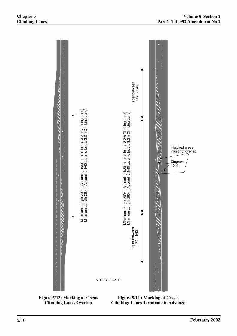
Volume 6 Section 1Part 1 TD 9/93 Amendment No 1
February 20025/16
Chapter 5Climbing Lanes

Volume 6 Section 1Part 1 TD 9/93 Amendment No 1
February 2002
Chapter 5Climbing Lanes
5/17
Volume 6 Section 1Part 1 TD 9/93 Amendment No 1
February 20025/18
Chapter 5Climbing Lanes

Volume 6 Section 1Part 1 TD 9/93 Amendment No 1
February 2002
LAYOUT – DUAL CARRIAGEWAYS
5.52 Options: Climbing lanes add another optionalelement to the treatment of vertical alignment. Theymay allow steeper, shorter, gradients to be considered,which would reduce earthworks, be less intrusive to thelocal environment, and offset the cost of the wider road.However from a traffic benefit viewpoint, the option offlattening gradients may often be preferable. Theimplications of long steep gradients on the downhillcarriageway should also be considered.
5.53 In certain situations, for example owing to landconstraints, it may be necessary to consider theadoption of narrow uphill lanes (see Paragraph 5.56),providing the climbing lane partially within the normalverge/marginal strip width to reduce the high costimplications, rather than omit the climbing lanealtogether. However, the effects on future networkmanagement and maintenance operations will need tobe considered. Such a Departure from Standards willrequire approval in the normal way.
5.54 Consideration should be given to extending theclimbing lane beyond the 2% gradient if a highproportion of HGVs or other slow moving vehiclescurrently cause problems or significantly reducecapacity. On existing roads an economical approach toextending climbing lanes is to remove the hard shoulderfor the distance for which additional climbing lanelength is needed, so that the additional lane can beadded within the road space. In cases where the hardshoulder is not sufficiently wide it may also benecessary to consider reducing the width of the runninglanes. Advice on the allowable reduction in the lanewidths is given in Paragraph 3.14. Further advice onreduction of lane widths and on the removal of anylength of hard shoulder should be sought from theOverseeing Organisation as both are deemed to be aDeparture from Standard.
5.55 On dual 3-lane motorways, if it is considered thata nearside merge of the climbing lane might be lesshazardous than in the offside lane where traffic volumesare high, advice should be sought from the OverseeingOrganisation; as a proposal for traffic to merge in thenearside lanes would be deemed a departure fromStandards. Experience from the introduction ofclimbing lanes on the M25, shows that the trafficmerging in the nearside lanes (1 and 2) can be lesshazardous than in the off-side lane where trafficvolumes are high.
5.56 Lane Widths: An overall additional full lanewidth of 3.65m shall be provided. In difficult areas, ordue to high structural or environmental costs, where fulllanes cannot be provided, a reduction is permitted byusing narrow lanes at pinch points (see Paragraph 3.14Lane Width Reductions at Pinch Points).
5.57 Layout at Start of Climbing Lane: The full widthof the climbing lane shall be provided at a point S in asimilar manner to that described for single carriagewayroads (Paragraph 5.34), but preceded by a taper of atleast 1/45, as shown in Figure 5/18. Wherever possiblethe additional width should be developed by utilisingthe road curvature to provide a smooth transition.
5.58 Climbing lanes may not be inserted directly at theexit of a roundabout but should allow for a distance ofat least 100m before the entry taper to avoid conflictingtraffic movements on exiting the roundabout. The entrytaper can be reduced in length from 1/45 to 1/30 owingto reduced vehicle speeds exiting the roundabout(Figure 5/19).
5.59 Layout at End of Climbing Lane: The full widthof the climbing lane shall be maintained up the gradientto a point F, in a similar manner to that described forsingle carriageway roads (Paragraph 5.36), but followedby a taper of 1/45. Where site conditions permit longertapers should be considered. A smooth transition shouldbe used wherever possible (Figure 5/20).
5.60 The climbing lane may precede a roundabout sothat the overtaking lane becomes the right hand entrylane into the roundabout. However, where the climbinglane ends at a distance greater than 500m from theroundabout it should be terminated in the normal way(Figure 5/21).
5.61 Sight Distance Requirements with ClimbingLanes: As the speeds of vehicles utilising the climbinglane will be considerably less than those on the rest ofthe carriageway, the climbing lane should bedisregarded in respect of provision of stopping sightdistance, which shall be checked from the centre of theinside lane of the original carriageway.
Chapter 5Climbing Lanes
5/19

Volum
e 6 Section 1P
art 1 TD
9/93 Am
endment N
o 1
February 2002 Figure 5/18: Start of Dual Carriageway Climbing Lane
5/20
Chapter 5
Clim
bing Lanes

Volum
e 6 Section 1P
art 1 TD
9/93 Am
endment N
o 1
February 2002
Figure 5/19: Start of Climbing Lane at Roundabout
Chapter 5
Clim
bing Lanes
5/21

Volum
e 6 Section 1P
art 1 TD
9/93 Am
endment N
o 1
February 2002 Figure 5/20: End of Dual Carriageway Climbing Lane
5/22
Chapter 5
Clim
bing Lanes

Volum
e 6 Section 1P
art 1 TD
9/93 Am
endment N
o 1
February 2002
Figure 5/21: Climbing Lane End at Roundabout Entry - Dual Carriageway
Chapter 5
Clim
bing Lanes
5/23

Volume 6 Section 1 Chapter 6Part 1 TD 9/93 Introduction to Coordinated Link Design
6. INTRODUCTION TO COORDINATED LINKDESIGN
ayan
phre
,
for,
a
s
General
6.1 The various elements detailed in this Standardshall be coordinated, together with cross-section andjunction layouts, so as to ensure that the threedimensional layout as a whole is acceptable in terms otraffic safety and operation, andeconomic/environmental effects. Single carriagewaydesign is given particular emphasis due to the problemof driver understanding and provision for overtaking.
Rural Roads
6.2 A general guide to the layout features appropriafor various types of road is given in Table 4. The tablerecommends edge treatments, access treatments andjunction types that would be suitable in broad terms foeach type of road.
Urban Roads
6.3 It is not possible to tabulate overall layoutcharacteristics for roads in urban areas in the same was for rural areas, as the constraints of the existing urbfabric will result in designs tailored to meet the sitespecific requirements. Urban Standards (embracingmandatory speed limits, Design Speeds generally 85kand below, and reduced cross-section design), are moconducive to safe conditions where the surroundingdevelopment is very much of an urban nature. UrbanStandards should not normally be used for roadspassing through other than short lengths of parklandsrecreational areas, non-built up waste land, etc., whichpresent an open aspect.
6.4 In urban areas, there will usually be less scope coordinating the geometric features than in rural areasalthough wherever economically/environmentallypracticable every effort should be made to do so. Thedemands of accommodating the road within the urbanfabric will frequently predominate.
6.5 Single two lane carriageway S2 or WS2 urbanroads of Type B, with no frontage access, no standingvehicles and negligible cross traffic, would normallyrepresent a radial or orbital bypass or new towndistributor. The design considerations in respect ofOvertaking Sections in Chapter 7 should be applied
wafreo
6ftpwcruh
ELECTRONIC COPY - N
June 1993 PAPER COPIES OF THIS ELEC
f
s
te
r
herever economically/environmentally practicable,lthough the constraints of the urban area will
requently not permit the flexibility of alignmentequired. In some cases, extra road width (ie WS2 orven 4 lane carriageways) can be used to providevertaking opportunity if economically feasible.
.6 Single two lane carriageways S2 or WS2 withrontage development, side roads, bus stops, etc withhe paramount need to create safe conditions foredestrians, are likely to be modest projects in an arehere comprehensive traffic management has beenarried out on the existing network and the new road iequired to extend or improve that management. It isnlikely that the coordinated design aspects containedereafter will be applicable in these cases.
OT FOR USE OUTSIDE THE AGENCY
TRONIC DOCUMENT ARE UNCONTROLLED 6/1

Chapter 6
Volum
e 6 Section 1
Introduction to Coordinated Link D
esignP
art 1 TD
9/93
ELE
CT
RO
NIC
CO
PY
- NO
T F
OR
US
E O
UT
SID
E T
HE
AG
EN
CY
PA
PE
R C
OP
IES
OF
TH
IS E
LEC
TR
ON
IC D
OC
UM
EN
T A
RE
UN
CO
NT
RO
LLED
June 19936/2
Category
( 1 )
Type of Road
( 2 )
Edge Treatment
( 3 )
Access Treatment
( 4 )
Minor RoadTreatment
( 5 )
Major JunctionTreatment
( 6 )
1
Normal( 7.3m )
CarriagewayS2
Kerbs and raisedverges. Pedestianfootways whererequired
Restriction of access toavoid standing vehiclesand concentrate turningmovements
Ghost islands Ghost islands
2
S2 1m hard strips asnormal
As 1 As 1 Ghost islands atlower end of trafficrange otherwisesingle lanedualling orroundabouts
3A
3B
S2
Wide Single *( 10m )
CarriagewayWS2
1m hard stripsPedestrian usageminimised
As 3A
As 1 and clearway atthe top of the trafficrange
As 3A
Ghost islands or singlelane dualling
As 3A
Single lanedualling orroundabouts
As 3A
4
WS2 * As 3A Restriction of access toavoid standing vehiclesand concentrate turningmovements. Clearway
Single lane dualling orroundabouts. Some sideroads stopped up.Occasional bridges athigher end of trafficrange.
At-graderoundabouts
* The approval of the Overseeing Department is required for schemes which will create more than 2km of these categories
Table 4: Recommended Rural Road Layouts

Volum
e 6 Section 1
Chapter 6
Part 1 T
D 9/93
Introduction to Coordinated Link D
esign
ELE
CT
RO
NIC
CO
PY
- NO
T F
OR
US
E O
UT
SID
E T
HE
AG
EN
CY
June 1993P
AP
ER
CO
PIE
S O
F T
HIS
ELE
CT
RO
NIC
DO
CU
ME
NT
AR
E U
NC
ON
TR
OLLE
D6/3
5
Dual 2 Lane ( 7.3m )
CarriagewaysAll Purpose
D2AP
Kerbs and raised verges or1m hard strips
Restriction of access toavoid standing vehiclesand concentratemovements.Clearway
Priority junctions. Noother gaps in the centralreserve.
At-grade roundabouts.Grade separation ifeconomically justified.
6 D2AP 1m hard strips
Restriction of accessseverely enforced.Clearway.
No minor junctions at-grade.No gaps in the centralreserve.
At-grade roundabouts atlower end of range.Otherwise full gradeseparation.
7A D2AP As 6No access except isolatedexisting access with leftturns only. Clearway
As 6 Full grade separation
7BDual 2 lane motorway
D2MMotorway standards Motorway Regulations None Motorway Standards
7C
Dual 3 lane( 11m )
CarriagewaysAll Purpose
D3AP
As 6 As 7A As 6 As 7A
8A D2M As 7B As 7B As 7B As 7B
8B D3AP As 6 As 7A As 6 As 7B
9Dual 3 laneMotorway
D3MAs 7B As 7B As 7B As 7B
10Dual 4 laneMotroway
D4M
As 7B As 7B
As 7BAs 7B
Category 10 requiresOverseeing Department Authorisation

Volume 6 Section 1 Chapter 7Part 1 TD 9/93 Single 2 Lane Carriageway Roads
7. SINGLE 2 LANE CARRIAGEWAY ROADS
nt,
eking
h
es
t of
g
General Principles
7.1 Single 2 lane carriageways up to 10m wide(running width) shall be designed with the objectives ofsafety and uncongested flow in mind. This Chaptergives methods of achieving these objectives. Althoughthey are to some extent related, for instance frustratedtraffic tends to lead to unsafe conditions, it is importantto identify some other aspects which if not taken intoaccount in the design may lead to a higher than averagproportion of serious accidents. Amongst these are:
a. Continuous flowing alignments,(Paragraphs 7.25 & 7.28).
b. Treatment of grade separation on singlecarriageways (Paragraph 7.35).
c. Single carriageway alternating with dualcarriageway, (Paragraphs 7.16, 7.36, 7.39, 7.40and 7.41 ).
d. Staged construction, (Paragraphs 7.37,7.38, 7.47 and 7.48).
7.2 Clearly identifiable Overtaking Sections for eitherdirection of travel are required to be frequently providethroughout the single carriageway according to thedesign flow, so that vehicles can maintain the DesignSpeed in off-peak conditions. In peak conditionsovertaking opportunities will be rare, neverthelesssteady progress will be possible for the majority ofvehicles if junctions are carefully designed, and ifclimbing lanes are provided wherever the forecast traffdemand is sufficient to justify a climbing lane accordingto Paragraph 5.2.
7.3 In easy terrain, with relatively straight alignmentsit may be economically feasible to provide forcontinuous overtaking opportunity by means ofconsistent provision of Full Overtaking Sight Distance(FOSD). Where significant curvature occurs or theterrain becomes increasingly hilly, however, the vergewidening and vertical crest requirements implicit in thisdesign philosophy will often generate highcost/environmentally undesirable layouts. Thealternative philosophy of clearly identifiable OvertakingSections, including climbing lanes to avoid heavyearthworks, interspersed with clearly Non-overtakingSections, will frequently result in a more cost effectivedesign provision. The trade-off between alternativealignments of the construction and user costs, includin
a
7aPacdtausct
O
o
P
g
ELECTRONIC COPY - NO
June 1993 PAPER COPIES OF THIS ELECTR
e
7.5 General: Overtaking sections are sections of roadwhere the combination of horizontal/vertical alignme
visibility, or width provision is such that clear
Overtaking sections, which are fully defined in
d a) Level Overtaking Sectionsb) Climbing Lane Sectionsc) Single Lane Downhill Sections
d) Dual or S4 Sections
It is necessary for the calculation of Overtaking Value(Paragraph 7.19) to define the method by which the
ic lengths of Overtaking Sections are assessed, and thmethod of measurement for each category of Overta
Section is described in the following Paragraphs. In
, a straight or right hand curve is achieved, or the widtprovision is sufficient for overtaking without crossingthe dividing line between opposing lanes. They willterminate either at a point where sight distance reducto FOSD/2m when approaching a Non-overtakingSection, or at a distance of FOSD/4m prior to an
obstruction to overtaking. (The detailed measuremensingle lane downhill sections, however, is described inParagraph 7.13).
ccidents, shall be tested by COBA (Scotland - NESA).
.4 In the coordination of vertical and horizontallignments, many of the principles contained inaragraph 8.7 (Category 7A and 8B dual carriageways)re equally applicable to the design of singlearriageway roads. However, the overriding need toesign for adequate overtaking will frequently supersede
he general desirability for full coordination of verticalnd horizontal alignment, with design concentratingpon the provision of straight Overtaking Sections. Atags and crests, however, designs should still behecked to ensure that the road in perspective does notake on a disjointed appearance.
vertaking Sections
pportunities for overtaking will occur.
aragraphs 7.7 to 7.16, comprise:
eneral, they will commence whenever either FOSD on
T FOR USE OUTSIDE THE AGENCY
ONIC DOCUMENT ARE UNCONTROLLED 7/1

Chapter 7 Volume 6 Section 1Single 2 Lane Carriageway Roads Part 1 TD 9/93
asured
r within
angent curve
here
truction
7.6 The method of measurement described in thefollowing section is based upon curvature/visibilityrelationships for S2 roads. Whilst the additional roadwidth of a WS2 provides much greater flexibility forovertaking, largely independent of curvature, thefollowing design rules should still be used to achieve aoptimal overtaking design.
7.7 Level Overtaking Sections : Level OvertakingSections are sections of single two lane carriageways,with normal centre of carriageway road markingsproviding clear opportunities for overtaking. Theyconsist of straight or nearly straight sections affordingovertaking in both directions (with horizontal radius ofcurvature greater than that shown in Table 5) and righhand curves, the commencement of which are providewith at least FOSD.
7
ELECTRONIC COPY - NOT
PAPER COPIES OF THIS ELECTR7/2
Design Speedkph
100 85 70 60 50
MinimumRadius ofStraight ornearly Straightsections (m)
8160 5760 4080 2880 2040
The section, which is shown in Figure 19, is meas follows:
7.8 Commencement : At the point on a straight orright hand curve where FOSD is achieved, eithe
n or without the highway boundary.
a) At a point FOSD/4m prior to the tpoint (or centre of transition) of a left hand
b) The point on a right hand curve wsight distance has reduced to FOSD/2m
td c) A point FOSD/4m prior to an obs
to overtaking (see Paragraph 7.18).
.9 Termination
FOSD
2
FOSD
OVERTAKING SECTION
For details of warning markingsat non-overtaking curves see Paragraphs 7.42 & 7.43
Tangent pointor centre of transition
OVERTAKING SECTION
FOSD
4
Table 5
Figure 19 Level Overtaking Sections
FOR USE OUTSIDE THE AGENCY
ONIC DOCUMENT ARE UNCONTROLLED June 1993

Volume 6 Section 1 Chapter 7Part 1 TD 9/93 Single 2 Lane Carriageway Roads
d
7.10 Climbing Lane Sections : Climbing lane sectionsare sections where priority uphill overtakingopportunities are provided by means of two uphill lanesseparated from the opposing downhill lane by means oa double white line, (either double solid orsolid/broken). The section, which is shown in Figure20, is measured as follows:
ELECTRONIC COPY - NO
June 1993 PAPER COPIES OF THIS ELECTR
7.11 Commencement : A point at the centre of thecommencing taper.
,f 7.12 Termination : A point FOSD/4m prior to the
centre of the finishing taper. However, if the followingsection is an Overtaking Section, it should be assume
to be contiguous with the climbing lane section.
OVERTAKING SECTION
For Details of Road Markingsat crests, see Paragraphs 5.8 & 5.9
FOSD
4
TaperTaper
Figure 20 Climbing Lanes
T FOR USE OUTSIDE THE AGENCY
ONIC DOCUMENT ARE UNCONTROLLED 7/3

Chapter 7 Volume 6 Section 1Single 2 Lane Carriageway Roads Part 1 TD 9/93
ll
uldhtace is
Design Speedkph
100 85 70 60 50
MinimumRadius ofSingle LaneDownhillSections (m)
2880 2040 1440 1020 720
7.13 Single Lane Downhill Sections : Single lanedownhill sections are sections of a single downhill laconstrained by a solid/broken double white line, whethe combination of visibility and horizontal curvatureprovide clear opportunities for overtaking when theopposing traffic permits. They consist of straight ornearly straight sections, and right hand curves with rgreater than those shown in Table 6.
Table 6
ELECTRONIC COPY - N
PAPER COPIES OF THIS ELEC7/4
The sight distance naturally occurring within the normalne highway boundaries at the radii shown in Table 6 wire be sufficient for downhill overtaking, and thus, for
single lane downhill lane sections, verges shall not bewidened to give FOSD. However, these sections shoonly be considered as Overtaking Sections on straig
adii grades or sag configurations, ie. when the road surfnot obscured by a vertical crest curve within:
7.15 Termination : A point FOSD/4m prior to the end
FOSD, or
the horizontal sight distance available around thecurve
The section, which is shown in Figure 21, is measuredas follows:
7.14 Commencement : The point where the right handcurve radius achieves the requisite value from Table 6.
of the requisite radius.
FOSD
4OVERTAKING SECTION
Minimum RHC Radius shown in table 6
Figure 21 Single Downhill Lanes
OT FOR USE OUTSIDE THE AGENCY
TRONIC DOCUMENT ARE UNCONTROLLED June 1993

Volume 6 Section 1 Chapter 7Part 1 TD 9/93 Single 2 Lane Carriageway Roads
oto).
l
7.16 Dual Sections : Dual Sections are sections withdual carriageways, which provide overtakingopportunities throughout their length. They should,however, only be overtaking provided in cases wherethe most economic method of improvement of a sectioof existing single carriageway is to provide a secondcarriageway alongside the first. Dual OvertakingSections within otherwise single carriageway roads shbe subject to the same overtaking length criteria asclimbing lane sections shown at Paragraph 7.10. S4sections (where space is limited) should be considereequivalent to Dual Sections in terms of assessment oovertaking.
Non-overtaking Sections
7.17 Non-overtaking sections are all left or right handcurves on level sections or single downhill lanes that dnot conform with the requirements of Paragraphs 7.7 7.16 (see also Non-overtaking crests Paragraph 7.19
ELECTRONIC COPY - NOT
June 1993 PAPER COPIES OF THIS ELECTR
n
all
df
Obstructions to Overtaking
7.18 At Grade Junctions: Major/minor junctions withghost islands or single lane dualling according to theOverseeing Department's current criteria, androundabouts should be considered as obstructions toovertaking if they are sited within an otherwiseOvertaking Section. The Overtaking Section shall beconsidered to terminate at a distance of FOSD/4m priorto the nose of the ghost or physical island, or theroundabout give way line, as shown in Figure 22.Simple junctions and accesses, however, with no centraghost or physical islands can be ignored.
OVERTAKING SECTIONFOSD
4
OVERTAKING SECTION
Note a simple priority junction with no ghost island layoutdoes not represent an obstruction to overtaking
a. Approach to Priority Junction (with ghost or solid island)
FOSD4
OVERTAKING SECTION
OVERTAKING SECTION
b. Approach to Roundabout
Figure 22 Obstructions to Overtaking
FOR USE OUTSIDE THE AGENCY
ONIC DOCUMENT ARE UNCONTROLLED 7/5

Chapter 7 Volume 6 Section 1Single 2 Lane Carriageway Roads Part 1 TD 9/93
FOSD
Non-overtaking Crests
7.19 A crest provided with less than FOSD shown inTable 3 should be considered as a Non-overtakingSection. The Overtaking section within which it occursshould be considered to terminate at the point at whichsight distance has reduced to FOSD/2, as shown inFigure 23. However, the use of Desirable Minimumcrest K values will result in a continuous sight distanceonly slightly above FOSD/2, and thus, theoretically, theOvertaking Section will be continuous over the crest(and warning markings will not be strictly justified). Theuse of Desirable crest K values is not recommended forsingle carriageway design (see Paragraph 2.8).
7/6
2
For details of warning markings atnon-overtaking crests, see Paragraph 7.43
FOSD
FOSD
2
FOSD
Figure 23 Non-overtaking Crest
ELECTRONIC COPY - NOT FOR USE OUTSIDE THE AGENCY
PAPER COPIES OF THIS ELECTRONIC DOCUMENT ARE UNCONTROLLED June 1993
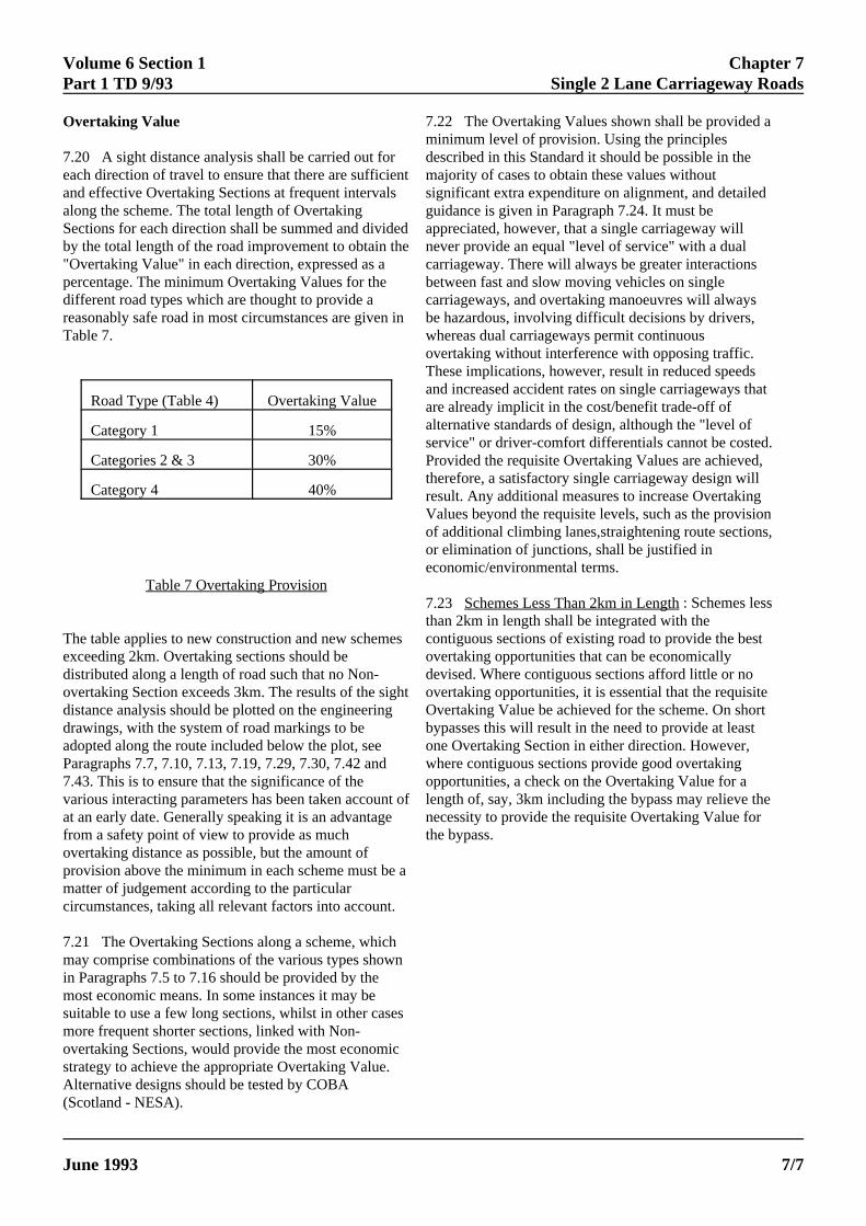
Volume 6 Section 1 Chapter 7Part 1 TD 9/93 Single 2 Lane Carriageway Roads
a
Road Type (Table 4) Overtaking Value
Category 1 15%
Categories 2 & 3 30%
Category 4 40%
Overtaking Value
7.20 A sight distance analysis shall be carried out foreach direction of travel to ensure that there are sufficienand effective Overtaking Sections at frequent intervalsalong the scheme. The total length of OvertakingSections for each direction shall be summed and divideby the total length of the road improvement to obtain the"Overtaking Value" in each direction, expressed as apercentage. The minimum Overtaking Values for thedifferent road types which are thought to provide areasonably safe road in most circumstances are given iTable 7.
Table 7 Overtaking Provision
The table applies to new construction and new schemeexceeding 2km. Overtaking sections should bedistributed along a length of road such that no Non-overtaking Section exceeds 3km. The results of the sighdistance analysis should be plotted on the engineeringdrawings, with the system of road markings to beadopted along the route included below the plot, seeParagraphs 7.7, 7.10, 7.13, 7.19, 7.29, 7.30, 7.42 and7.43. This is to ensure that the significance of thevarious interacting parameters has been taken accountat an early date. Generally speaking it is an advantagefrom a safety point of view to provide as muchovertaking distance as possible, but the amount ofprovision above the minimum in each scheme must be matter of judgement according to the particularcircumstances, taking all relevant factors into account.
7.21 The Overtaking Sections along a scheme, whichmay comprise combinations of the various types shownin Paragraphs 7.5 to 7.16 should be provided by themost economic means. In some instances it may besuitable to use a few long sections, whilst in other casesmore frequent shorter sections, linked with Non-overtaking Sections, would provide the most economicstrategy to achieve the appropriate Overtaking Value.Alternative designs should be tested by COBA
7.mdemsiguapnecabecabewovTanaralsePthreVoforec
7.thcoovdeovObyonwopleneth
ELECTRONIC COPY - NOT
June 1993 PAPER COPIES OF THIS ELECTRO
(Scotland - NESA).
t
d
n
s
t
of
22 The Overtaking Values shown shall be provided ainimum level of provision. Using the principlesscribed in this Standard it should be possible in the
ajority of cases to obtain these values withoutgnificant extra expenditure on alignment, and detailedidance is given in Paragraph 7.24. It must bepreciated, however, that a single carriageway willver provide an equal "level of service" with a dualrriageway. There will always be greater interactionstween fast and slow moving vehicles on singlerriageways, and overtaking manoeuvres will always hazardous, involving difficult decisions by drivers,
hereas dual carriageways permit continuousertaking without interference with opposing traffic.
hese implications, however, result in reduced speedsd increased accident rates on single carriageways thate already implicit in the cost/benefit trade-off ofternative standards of design, although the "level ofrvice" or driver-comfort differentials cannot be costed.
rovided the requisite Overtaking Values are achieved,erefore, a satisfactory single carriageway design willsult. Any additional measures to increase Overtakingalues beyond the requisite levels, such as the provision additional climbing lanes,straightening route sections, elimination of junctions, shall be justified inonomic/environmental terms.
23 Schemes Less Than 2km in Length : Schemes lessan 2km in length shall be integrated with thentiguous sections of existing road to provide the bestertaking opportunities that can be economicallyvised. Where contiguous sections afford little or noertaking opportunities, it is essential that the requisite
vertaking Value be achieved for the scheme. On shortpasses this will result in the need to provide at leaste Overtaking Section in either direction. However,
here contiguous sections provide good overtakingportunities, a check on the Overtaking Value for a
ngth of, say, 3km including the bypass may relieve thecessity to provide the requisite Overtaking Value for
e bypass.
FOR USE OUTSIDE THE AGENCY
NIC DOCUMENT ARE UNCONTROLLED 7/7
Chapter 7 Volume 6 Section 1Single 2 Lane Carriageway Roads Part 1 TD 9/93
7.24 Means of Improving Overtaking Value : As wellas ensuring sufficient overtaking opportunities, themethod also controls the spacing of junctions. If thecriteria are not met initially for any alignment it may benecessary to:
a) Modify the junction strategy by stoppingup, bridging, or diverting some side roads.
b) Adjust the alignment to produce morestraight sections.
c) Introduce climbing lanes on hillspreviously not considered justified because of lowtraffic flow.
d) Introduce roundabouts at the moreheavily trafficked priority junctions to createsharper changes of direction and improveOvertaking Section lengths.
e) Introduce lengths of WS2 road at suitablelocations. Whilst this will not improve theOvertaking Value according to the formalmethods described in Paragraphs 7.5 to 7.16,WS2 sections will nevertheless, by the extra roadwidth, increase flexibility and reduce frustration.
f) Introduce more extensive sections of S4or dual carriageways.
Alternative means of improving Overtaking Valuesshould be tested by COBA (Scotland - NESA) todetermine their economic implications. This will takeinto account any changes in user costs due to increasedjunction delays, diversion costs, or increased speeds dueto increased road width, etc. The minimum overalladditional cost of improving Overtaking Values in termsof loss of NPV should be identified, and an assessmentmade taking all factors into account, including the effecton the road user.
The extra cost of provision of 2.7m road width toprovide a climbing lane at a hill previously consideredunjustified (or a section of WS2 on a constrained levelroad alignment) may be justified on the total balance ofadvantage. As the wider road will also provide someimproved benefits, the resulting loss of NPV may onlybe minor and thus a small price to pay for theunquantifiable benefits to traffic of improving theOvertaking Value.
ELECTRONIC COPY - NOT FOR USE OUTSIDE THE AGENCY
PAPER COPIES OF THIS ELECTRONIC DOCUMENT ARE UNCONTROLLED June 19937/8

Volume 6 Section 1 Chapter 7Part 1 TD 9/93 Single 2 Lane Carriageway Roads
Figure 24 Horizontal Curve Design
Horizontal Curve Design
7.25 The use of mid-large radius curves is counterproductive, inhibiting the design of clear OvertakingSections. They produce long dubious overtakingconditions for vehicles travelling in the left hand curvdirection, and simply reduce the length of overtakingstraight that could otherwise be achieved.
ELECTRONIC COPY
June 1993 PAPER COPIES OF THIS EL
e
Figure 24 shows a curve selection chart for horizontalcurves, which illustrate the bands of radii (relative toDesign Speed) and their applicability in the design ofsingle carriageways.
- NOT FOR USE OUTSIDE THE AGENCY
ECTRONIC DOCUMENT ARE UNCONTROLLED 7/9

Chapter 7 Volume 6 Section 1Single 2 Lane Carriageway Roads Part 1 TD 9/93
7.26 Wherever possible, level Overtaking Sections anclimbing lanes shall be provided as straight or nearlystraight sections (band A), thus providing an OvertakinSection for both directions of travel (V²/R < 1.25).
7.27 Where straight sections are not possible, lowerradii will result in right hand curve (RHC) OvertakingSections:
On level sections following the achievement ofFOSD
On single lane downhill sections
The lower limit of Band B (V²/R = 3.53) shown forRHC Overtaking Sections should be considered as theminimum radius for use in designing OvertakingSections. At this level visibility for left hand curve(LHC) traffic has deteriorated significantly, and amaximum verge width of 10.65m would be required tomaintain FOSD within the highway for RHC traffic.
7.28 The use of radii in Band C (V²/R = 3.53-10) ishighly undesirable and not recommended, as theyintroduce long sections with dubious overtakingconditions for LHC traffic. Where visibility isconstrained within the highway, either excessive vergewidening would be required to maintain FOSD for RHCtraffic, or the natural visibility without verge wideningat these radii would result in dubious overtakingconditions for the RHC traffic also. It is a paramountprinciple, therefore, that design should concentrate onlon Bands A and B for clear Overtaking Sections, andBand D for clear Non-overtaking Sections.
7.29 Non-overtaking Sections should be designedusing the radii shown in Band D (V²/R = 10-20), wherethe radius is sufficiently small to represent a clearlyNon-overtaking Section requiring the use of warninglines (but see Paragraph 7.43 re. road markings). Radof Non-overtaking Sections should be chosen around tcentre of Band D (V²/R = 14) to strike a balancebetween providing clear Non-overtaking Sections andavoiding steep superelevation.
V
7tovFHlaaaavmsvMDpleleb
7ccufhsDinMp7
J
7tcolac
ELECTRONIC COPY - NOT
PAPER COPIES OF THIS ELECTRO7/10
d
g
y
iihe
ertical Curve Design
.30 The vertical alignment shall be coordinated withhe horizontal alignment to ensure the most efficientvertaking provision. On level Overtaking Section, theertical curvature shall be sufficient to provide forOSD in accordance with Paragraphs 2.3 to 2.5.owever, for Non-overtaking Sections and climbingnes, the use of large crest curves is quite unnecessarynd not recommended. Unless a vertical curve can have large enough K value to provide FOSD (thus formingn Overtaking Section) a long section of dubiousisibility will result, which cannot justify warningarkings , but inadequate sight distance for overtaking
till exists (see Paragraph 7.19). Therefore, provided a Kalue of one Design Speed step below Desirableinimum K value is achieved, further improvement toesirable Minimum K value or above will be counterroductive, simply increasing costs, increasing thength of dubious crest visibility, and reducing thength of clear Overtaking Sections that could otherwisee achieved.
.31 Horizontal and vertical visibility shall be carefullyoordinated to ensure that Sight Distance at curves onrests is correlated. For example, it would bennecessary to acquire additional verge width to provide
or Desirable Minimum Stopping Sight Distance in theorizontal sense, when the crest only provides atopping sight distance of one Design Speed step belowesirable Minimum Stopping Sight Distance. Tocrease both verge width and crest radius for Desirableinimum Stopping Sight Distance would be counterroductive in overtaking design as in Paragraphs 7.25 to.31.
unction Strategy
.32 The aim should be to provide drivers with layoutshat have consistent Standards and are not likely toonfuse them. On lengths of inter-urban road, sequencesf junctions should not therefore involve many differentyout types. For example, a length of route or bypass
ontaining contiguous roundabouts, single lane dualling,ghost islands, simple priority junctions and gradeseparation would inevitably create confusion anduncertainty for drivers and cause accidents on thataccount. The safest road schemes are usually the moststraightforward ones that contain no surprises for thedriver.
FOR USE OUTSIDE THE AGENCY
NIC DOCUMENT ARE UNCONTROLLED June 1993

Volume 6 Section 1 Chapter 7Part 1 TD 9/93 Single 2 Lane Carriageway Roads
aking
as as
oe 25.
7.33 Major/minor junctions with ghost islands or localsingle lane dualling and roundabouts represent anobstruction to overtaking. To achieve maximumovertaking efficiency, therefore, straight OvertakingSections should be located wherever possible betweenjunctions, which can be located in Non-overtakingSections. Visibility to the junction shall be a minimumof Desirable Stopping Sight Distance, and advancewarning arrows to islands should be made visible fromthe overtaking straight wherever possible.
ELECTRONIC COPY - NOT
June 1993 PAPER COPIES OF THIS ELECTR
7.34 Use of a roundabout will enable a change ofalignment at a junction, thus optimising the Overt
Sections either side. As an alternative to continuinglarge radius curves into the roundabout with only
unidirectional overtaking, it is preferable to utilisestraight section followed by a non-overtaking radiuthe final approach, in order to optimise the use of tw
directional overtaking straights, as shown in Figur
Overtaking Sections
FOSD4
Large radius curve minimises overtakingfor vehicles on left hand curve direction
FOSD4
Overtaking Sections
Figure 25 Use of Roundabout to Change Alignment
FOR USE OUTSIDE THE AGENCY
ONIC DOCUMENT ARE UNCONTROLLED 7/11

Chapter 7 Volume 6 Section 1Single 2 Lane Carriageway Roads Part 1 TD 9/93
7.35 Designs involving grade separation of singlecarriageway roads should be treated with caution. Somegrade separated crossings will be necessary forundesirable side road connections and for agriculturalpurposes. Experience has shown that frequentoverbridges and the resulting earthworks create theimpression of a high speed road, engendering a level ofconfidence in the road alignment that cannot be justifiedon single carriageways, where opposing traffic travelson the same carriageway. The provision of regular atgrade junctions with ghost islands, local dualling orroundabouts will maintain the impression of a singlecarriageway road. Where crossing flows are high, orlocal topographical conditions would suggest the needfor a grade separated junction, the single quadrant linkwith a conventional ghost island junction, as shown inFigure 26, will maintain the impression of a singlecarriageway road, with conventional single carriagewayturning movements and minimise the disruptive rightturn movement onto the major road. The link should belocated in the quadrant that will ensure the larger turningmovements become left turns onto and right turns offthe major road. With the highest levels of traffic flow, itmay be necessary to provide roundabouts at one or bothends of the link road. The use of slip merges can beconfusing on single carriageways and create problemswith merging into a single lane. They destroy the overallimpression of a single carriageway, and shall not beused.
ELECTRONIC COPY - NOT FOR
PAPER COPIES OF THIS ELECTRONIC7/12
1 3
2 4
or
or
Major movements Siting of loop
Quadrant 1 or 4
Quadrant 2 or 3
Figure 26 Single Quadrant Link
USE OUTSIDE THE AGENCY
DOCUMENT ARE UNCONTROLLED June 1993

Volume 6 Section 1 Chapter 7Part 1 TD 9/93 Single 2 Lane Carriageway Roads
ga
Changes in Carriageway Width
7.36 Changes from dual to single carriageways are apotential hazard situation and the aim in newconstruction should be to provide continuity of roadtype, either single or dual carriageway layout, on anymajor section of a route which carries consistentlysimilar traffic, subject to satisfactory economic andenvironmental assessments. Exceptions are describedbelow. Where it is not possible to achieve an adequateOvertaking Value by means of level OvertakingSections or climbing lanes, the impression of a singlecarriageway road shall be maintained by utilising WS2sections at suitable locations (see Paragraph 7.24), orshort sections of S4, rather than introducing sections ofdual carriageway.
7.37 Single carriageways of a type containing wideverges and extensive earthworks prepared for eventualdualling create the illusion of driving on a dualcarriageway, which leads to abnormally high seriousaccident rates. Where staged construction is part of thedesign or there are safety problems at existing sites,provision shall be made to avoid giving drivers anillusion that they are on a dual carriageway rather thanon a single carriageway such as:
a) Fencing of a permanent appearance at averge width (normally 3.5m) from the channel ofthe constructed carriageway on the side reservedfor the future carriageway; combined with quickgrowing evergreen planting at the fence.
b) Clear signing and marking indicating theexistence of two way traffic.
c) Where a changeover occurs at aroundabout, a narrow physical splitter island notless than 50 metres long on the single carriagewayside of the roundabout followed by hatching.
7.38 Where there is an overbridge designed for aneventual second carriageway, the illusion of a secondrunning carriageway shall be removed by planting andearth mounds as shown in Figure 27.
7.39 Where a lighter trafficked bypass occurs within anotherwise dual carriageway route, a single carriagewaymay be acceptable provided the terminal junctions such
7.4carproacha dor ab
ELECTRONIC COPY - NOT FO
June 1993 PAPER COPIES OF THIS ELECTRONI
as roundabouts give a clear indication to drivers ofchanged Standards see Figure 28, Paragraph 7.37 b ac.
nd
Figure 27
0 In circumstances where a length of newriageway alongside an existing single carriagewayvides the most suitable and economic means ofieving a dualled Overtaking Section and where suchual carriageway returns to single carriageway widthin any other case, the change in width shall be madeundantly clear to drivers by:
a) Signing and marking indicating theexistence of the single carriageway.
b) Providing a length of central reserve inadvance of the taper such that drivers approachinthe single carriageway can see across it, to have clear view of the approaching traffic moving on tothe dual carriageway.
Figure 28
R USE OUTSIDE THE AGENCY
C DOCUMENT ARE UNCONTROLLED 7/13

Chapter 7 Volume 6 Section 1Single 2 Lane Carriageway Roads Part 1 TD 9/93
able.
ises
,
7.20 toving
s on
ned
g
7.41 If lengths of dual carriageway within a generalsingle carriageway road or vice-versa are unavoidabthey shall be at least 2km in length and preferably 3kand major/minor junctions shall be avoided within 1kilometre of the end of the central reserve on either tof carriageway, see Paragraph 7.39.
Road Markings
7.42 The continuous provision of a stopping sightdistance up to one Design Speed step below DesiraMinimum will result in the visibility provision beingabove the threshold of double white lines, althoughwarning lines to will be required at non-overtakingcurves and solid/dotted combinations will be requiredclimbing lanes. There are, however, a limited numbeapplications of double solid white lines, for example crests at the end of climbing lanes, double white lineshall be used at the commencement of the singledownhill lane, in accordance with Paragraph 5.11 anFigures 13-15.
7.43 At non-overtaking horizontal curves, and crest(see Paragraph 7.30), where warning markings wounormally be required, the markings may be strengthewith a hatched marking as shown in Figure 29,especially following Overtaking Sections, in order tomake clear to drivers the presence of undesirableovertaking conditions.
ELECTRONIC COPY - NO
PAPER COPIES OF THIS ELECT7/14
lylem,
ype
Chapters 1 to 5, Elements of Design, will be applicble
7.45 Where, however, the need for improvement arfrom congested conditions, or from a restricted
alignment providing an unsatisfactory regime of flow on attention should be focused upon the provision of
r of adequate Overtaking Sections, as in Paragraphs at 7.24. One of the most economic methods of impros Overtaking Value is the provision of climbing lane
hills, where slow moving vehicles create severed congestion and consequent delays, (or a second
carriageway added to the first), instead of a major
s elsewhere.ld
Existing Single Carriageway Improvements
7.44 The design Standards contained in the precedinparagraphs apply generally to lengths of new singlecarriageway construction, from short bypasses anddiversions to extensive new single carriageway routes.When dealing with existing rural roads, the need forimprovements will frequently be dictated by evidentdangerous bends, junctions, narrow sections, hills, etcfor the improvement of which the Standards shown in
realignment to create a level Overtaking Section
Hatched marking 1m wide(within normal carriageway)
Figure 29 Hatched Road Marking at Non-overtaking Curves & Crests
T FOR USE OUTSIDE THE AGENCY
RONIC DOCUMENT ARE UNCONTROLLED June 1993

Volume 6 Section 1 Chapter 7Part 1 TD 9/93 Single 2 Lane Carriageway Roads
7.46 On a long length carrying consistently similartraffic which has been defined for more majorimprovement, it is important to have a comprehensivestrategy to maintain an acceptable level of service andsafe conditions, and ways of implementing the strategyin stages must be evolved to suit expenditure profiles.The techniques contained throughout Chapters 6 and 7shall be used when formulating the overall strategy,which, after elimination of dangerous bends, junctionimprovements, etc, should concentrate upon theprovision of adequate Overtaking Sections. Whilst thevertical and horizontal alignments shall be coordinatedin accordance with the preceding paragraphs for allnewly constructed diversions and bypasses, there willfrequently be little necessity for such coordination onthe remaining sections which, although not conformingto formal Standards, may not demonstrate any operatingproblems.
Staged Construction
7.47 Where a single carriageway is being considered asa first stage of an eventual dual carriagewayimprovement, the single carriageway shall be designedin accordance with the coordinated design aspectsshown in Chapter 7. This will ensure that the impressionof an essentially at-grade single carriageway road ismaintained. Where it is economic to carry out someearthworks or bridgeworks for the dual carriageway inthe first stage, care must be taken to ensure that thewider formation and bridges do not create the illusion ofa dual carriageway. At bridges, such an illusion can beavoided by the methods described in Paragraph 7.38,and generous planting can reduce the overall impressionof space.
7.48 The overriding requirements for clear OvertakingSections in the first stage design will mean that theflowing alignment requirements for dual carriageways(as shown in Paragraph 8.7) will not be possible ordesirable. However, first stage designs should bechecked to ensure that the horizontal and verticalalignments are phased sufficiently to eliminate any areaswhere misleading visual effects in perspective mightoccur, for example, broken back alignments.
ELECTRONIC COPY - NOT FOR USE OUTSIDE THE AGENCY
June 1993 PAPER COPIES OF THIS ELECTRONIC DOCUMENT ARE UNCONTROLLED 7/15

Volume 6 Section 1 Chapter 8Part 1 TD 9/93 Dual Carriageways and Motorways
8. DUAL CARRIAGEWAYS AND MOTORWAYS
General Principles
8.1 All purpose dual carriageways and motorwaysshall be designed to permit light vehicles to maintainthe Design Speed. Subject to traffic conditions, lightvehicles can overtake slower moving vehiclesthroughout, without conflict with opposing traffic, anddrivers are free to travel at a speed controlled only bythe constraints described in Chapter 1. Unlike singlecarriageways, therefore, there is no limitation upon theuse of horizontal or vertical curves in excess of thevalues for one Design Speed Step below DesirableMinimum values, and the coordination of designelements will mainly involve the design andoptimisation of aesthetic alignments.
8.2 In the coordination of vertical and horizontalalignments, the principles contained in Paragraph 8.7(Category 7a and 8b dual carriageways) are generallydesirable for all dual carriageway designs. However,for the lower categories of design, with consequentlylower traffic flows, a high Standard of aesthetic designmay frequently not be justifiable, particularly where thedual carriageway represents an alternative to a singlecarriageway.
All Purpose Dual Carriageways
8.3 Category 5 (Table 4) : This is the lowest categoryof dual carriageway which will normally represent analternative layout option to single carriageway types Sor WS2.
8.4 The vertical alignment should follow thetopography closely with the horizontal alignmentphased to match. All junctions should be at-grade, wiroundabouts at the more heavily trafficked intersectionalthough where economically/environmentally feasiblegrade separated solutions should be provided.
8.5 Major/Minor junctions on dual carriageways are source of accidents, but collecting together side roadsincreased provision of grade separation are costlyalternatives that may not be economically justified. Furthermore, where the dual carriageway is beingassessed as an alternative option to a singlecarriageway, the additional costs of higher Standards junction or alignment provision, together with theresulting higher overall earthworks and structuralimplications, may well cause the dual carriageway
iacacsedewd
8gpuwwtdehrgvta
8hisst
ELECTRONIC COPY - NO
June 1993 PAPER COPIES OF THIS ELECTR
option to be so costly as to be uneconomic, in spite
2
ths,,
a or
of
of
ts inherently superior performance in terms of linkccidents and user costs. A category 5 dualarriageway, therefore, should be designed essentiallys an at-grade alternative to an at-grade singlearriageway, and elements of design, such as junctions,hould be enhanced only if there is economic ornvironmental justification for doing so. In this way,ual carriageways will frequently demonstrate superiorconomic performance to a single carriageway at flowsell below the upper limits of single carriagewayemand flows.
.6 Categories 6 & 7c (Table 4) : In these categories,aps in the central reserve for turning traffic are notermissible, and major/minor junctions shall not besed. Minor side roads shall be stopped up, providedith left in/left out connections, or grade separatedithout connection. In category 6, major intersection
ypes, which may include roundabouts, will beetermined by site conditions, traffic demand, andconomic/environmental effect. In category 7,owever, the high costs of delays caused byoundabouts will normally result in more economicrade separated solutions. The combinedertical/horizontal alignments should follow theopography as much as possible, without purposelychieving a "motorway" type of flowing alignment.
.7 Categories 7a and 8b (Table 4) : These are theighest categories of all-purpose road, where all
ntersections, both major and minor, shall be gradeeparated. A smooth flowing alignment is required forustained high speeds. The following are the principleso be followed in securing a satisfactory alignment.
a) Care shall be taken to ensure thatembankments and cuttings do not make severebreaks in the natural skyline.
b) When negotiating a ridge in cutting orpassing through a broad stretch of woodland, theroad shall be on a curve whenever possible so asto preserve an unbroken background.
c) Short curves and straights shall not beused. Adjacent curves shall be similar in length.
d) Small changes of direction shall not bemade, as they give the perspective of the roadahead a disjointed appearance.
e) Curves of the same or opposite sense
T FOR USE OUTSIDE THE AGENCY
ONIC DOCUMENT ARE UNCONTROLLED 8/1

Chapter 8 Volume 6 Section 1Dual Carriageways and Motorways Part 1 TD 9/93
n
which are visible from one another shall not beconnected by a short straight. It is better tointroduce a flat curve between curves of the samsense, or to extend the transition curves to acommon point between curves of the oppositesense.
f) Changes in horizontal and verticalalignment shall be phased to coincide wheneverpossible. This is very important with horizontalcurves sharper than 2,000m radius and verticalcurves of less than 15,000m radius.
g) Flowing alignment can most readily beachieved by using large radius curves rather thastraights.
h) The profile of the road over bridges musform part of the easy flowing alignment.
i) At the start of horizontal curvessuperelevation must not create large flat areas owhich water would stand.
j) Horizontal and vertical curves shall bemade as generous as possible at interchanges iorder to enhance sight distances.
k) Sharp horizontal curvature shall not beintroduced at or near the top of a pronouncedcrest. This is hazardous especially at nightbecause the driver cannot see the change inhorizontal alignment.
l) The view of the road ahead shall notappear distorted by sharp horizontal curvatureintroduced near the low point of a sag curve.
M
8haptgtu
8Cf
ELECTRONIC COPY - NOT
PAPER COPIES OF THIS ELECTRO8/2
e
n
t
n
otorways
.8 The high standard of motorway design results inigh speeds throughout, by complete elimination ofccess other than at interchanges and service areas,rohibition of usage by pedestrians and certain vehicle
ypes and use of hard shoulders, coupled with theenerous flowing alignment. Design Speeds shall be in
he 120 kph category for rural motorways but less inrban cases.
.9 The relevant alignment Standards are given inhapters 2 to 5 and the rules in Paragraph 8.7 shall be
ollowed. Additionally:
Horizontal and Vertical Curves should be asgenerous as possible throughout.
To relieve the monotony of driving on a roadwith such good extensive forward visibility, longsections of the road should be aligned to give aview of some prominent feature ahead.
FOR USE OUTSIDE THE AGENCY
NIC DOCUMENT ARE UNCONTROLLED June 1993
Volume 6 Section 1Part 1 TD 9/93 Amendment No 1
February 2002
Chapter 9References
9/1
9. REFERENCES
TD 42/95 Geometric Design Of Major/MinorJunctions. (DMRB 6.2)
TD 46/97 Traffic Flow Ranges For Use In TheAssessment Of New Rural Roads.(DMRB 5.1)
TD 79/99 Traffic Capacity Of Urban Roads.(DMRB 5.1)
Environmental Assessment. (DMRB 11.3)
COBA Cost Benefit Analysis. (DMRB 13.1)
QUADRO Queues and Delays at Roadworks.(DMRB 14.1)
NESA Economic Assessment of RoadSchemes in Scotland, The NESAManual. (DMRB 15.1)
Multi Modal Appraisal
NRTF National Road Traffic Forecasts, GB
Traffic Signs Regulations and General Directions
Traffic Signs Manual Chapter 5, Road Markings
Highways Act 1980
Roads Scotland Act 1984
Roads in Upland Areas: A Design Guide. Welsh Office
Roads in Lowland Areas: A Design Guide. WelshOffice

Volume 6 Section 1Part 1 TD 9/93 Amendment No 1
February 2002 10/1
10. ENQUIRIES
All technical enquiries or comments on this Standard should be sent in writing as appropriate to:
Chief Highway EngineerThe Highways AgencySt Christopher HouseSouthwark Street G CLARKELondon SE1 0TE Chief Highway Engineer
Chief Road EngineerScottish Executive Development DepartmentVictoria QuayEdinburgh J HOWISONEH6 6QQ Chief Road Engineer
Chief Highway EngineerThe National Assembly for WalesCynulliad Cenedlaethol CymruCrown BuildingsCathays Park J R REESCardiff CF10 3NQ Chief Highway Engineer
Director of EngineeringDepartment for Regional DevelopmentRoads ServiceClarence Court10-18 Adelaide Street G W ALLISTERBelfast BT2 8GB Director of Engineering
Chapter 10Enquiries

Volume 6 Section 1Part 1 TD 9/93 Annex A
HARMONIC MEAN VISIBILITY
1. The Harmonic Mean Visibility VISI shallbe measured over a minimum length of about 2km inthe following manner. Measurements of sight distanceshall be taken in both directions at regular intervals(50m for sites of uneven visibility, 100m for sites withgood visibility) measured from eye height of 1.05m toan object height of 1.05m, both above the centre line ofthe road surface. Sight distance shall be the true sightdistance available at any location, taking into accountboth horizontal and vertical curvature, including anysight distance available across verges and outside thehighway boundary wherever sight distance is availableacross embankment slopes or adjoining land, as shownin Figure A.
V3
1 2 3 4 5 67
8
9
50m or 100m
Figure A Measurement of HMV
ELECTRONIC COPY - NOT FOR USE OUTSIDE THE AGENCY
June 1993 PAPER COPIES OF THIS ELECTRONIC DOCUMENT ARE UNCONTROLLED A/1

Volume 6 Section 1Annex A Part 1 TD 9/93
t
e
,
,
VISI ' n1V1
%1V2
%1V3
....% 1Vn
2. Harmonic Mean Visibility is the harmonicmean of individual observations, such that:
where:-
n = number of observations V1 = sight distance at point 1, etc.
3. For existing roads, an empirical relationshiphas been derived which provides estimates of VISI givenin bendiness and verge width (applicable up to VISI =720m) i.e.
Log VISI = 2.46 + VW/25 - B/40010
where:
VW = Average verge width (averaged forboth sides of the road)
B = Bendiness (Degree per km - minimumLength of about 2 km)
This relationship is valid for existing roads, but on longstraight roads, or where sight distance is available outsidethe highway boundary, significant underestimates of VISIwill result.
4. For preliminary route analysis, wheredetailed measurements of sight distance are not availablethe following typical values should be used:
4.1 On long virtually straight roads, or where theroad is predominantly on embankment affording highvisibility across embankment slopes or adjoining levelland:
VISI = 700m
4.2 If a new road is designed with continuousovertaking visibility, with large crest K values and wideverges for visibility:
VISI = 500m
pr
4.cona
us
ELECTRONIC COPY - NOT FO
PAPER COPIES OF THIS ELECTRONIA/2
4.3 Where a new road is designed with frequenOvertaking Sections, but with stopping sight distance
although the empirical formula shown in 3 above can b
ovision at all sharp curves:
VISI = 300m
4 Where an existing single carriagewayntains sharp bends, frequent double white line sectionsrrow verges, etc.
VISI = 100 - 200m
ed if Bendiness is available.
R USE OUTSIDE THE AGENCY
C DOCUMENT ARE UNCONTROLLED June 1993