dma profibus manual...6 configuration for the siemens tia portal ..... 30 6.1 setup the network...
TRANSCRIPT

Date: 15.03.2019 Rev: R1.3 File: DMA Profibus certified Manual E R1.3 20190315.doc Author: Bm Page: 1 of 45
DMA Profibus Manual
Revision History
Revision Date Description R_1.0 10.12.2014 Copy from the V2.7 of standard documentation added PNO Certification
R_1.1 11.12.2014 Added screenshots from the actual GSD file
R_1.2 28.01.2014 CMD15 for V72.xxy definition
R_1.3 15.03.2019 Configuration for TIA Portal included

Date: 15.03.2019 Rev: R1.3 File: DMA Profibus certified Manual E R1.3 20190315.doc Author: Bm Page: 2 of 45
Table of Content
1 Features ........................................................................................................................................................................ 3
1.1 Used GSD File ....................................................................................................................................................... 3
1.2 Supported DMA SW-versions ................................................................................................................................ 3
1.3 PNO Certificate ...................................................................................................................................................... 4
1.4 Special information for Multi-Slave Nodes ............................................................................................................. 5
1.5 General information about TADR (Telegram Address) .......................................................................................... 5
1.6 General information about CMD (Command) and SADR (Slave Address) ............................................................ 5
2 Front View: Address Selection and Connectors ............................................................................................................ 6
2.1 Front View: Single Module Version (node with one module connected) ................................................................ 6
2.2 Front View: Multiple-Slave Version (node with multiple modules connected) ........................................................ 7
3 Simple commands......................................................................................................................................................... 8
3.1 CMD = 3, Master Read parameters (7 bytes) ........................................................................................................ 8
3.2 CMD = 3, Response from Slave (4 + CNT bytes) .................................................................................................. 8
3.3 CMD = 3, Error from Slave (4 bytes) ...................................................................................................................... 9
3.4 CMD = 6, Master Write single parameter (7 bytes) .............................................................................................. 10
3.5 CMD = 6, Response from Slave (7 bytes) ............................................................................................................ 10
3.6 CMD = 6, Error from Slave (4 bytes) .................................................................................................................... 11
3.7 Telegram example CMD = 6, CMD = 3 ................................................................................................................ 12
3.8 Additional examples CMD = 6 .............................................................................................................................. 13
4 Complex commands ................................................................................................................................................... 14
4.1 CMD = 15, Master writes multiple parameters (3+5·module bytes) ..................................................................... 14
4.2 CMD = 15, Response from Slave (9 bytes) .......................................................................................................... 15
4.3 CMD = 15, Error from Slave (4 bytes) .................................................................................................................. 15
4.4 Examples, CMD = 15 ........................................................................................................................................... 16
4.4.1 Single slave (SW Version 15.xxy) ................................................................................................................. 16
4.4.2 Multiple-slave (3 DMA modules, SW Version 15.xxy) ................................................................................... 16
4.5 CMD = 15, structure of Profibus telegram definition, depending on SW Versions ............................................... 18
4.5.1 General ......................................................................................................................................................... 18
4.5.2 Version: V15.xxy, open loop, one valve with two solenoids, , Mode 1 .......................................................... 20
4.5.3 Version: V22.xxy, open loop, two valves with one solenoid each, , Mode 2 ................................................. 21
4.5.4 Version: V32.xxy, V72.xxy, closed loop, Mode 3, 4 ...................................................................................... 22
4.5.5 Version: V32.xxy, closed loop, Mode 6 ......................................................................................................... 23
4.5.6 Version: V32.xxy, closed loop, Mode 8 ......................................................................................................... 24
5 Siemens S7 implementation of the “Multiple-slave” (3 DMA modules)........................................................................ 25
5.1 Hardware configuration ........................................................................................................................................ 25
5.2 CMD = 15, protocol configuration ........................................................................................................................ 29
6 Configuration for the SIEMENS TIA portal .................................................................................................................. 30
6.1 Setup the network configuration for the DMA module .......................................................................................... 30
6.1.1 Download and install the GSD file. ............................................................................................................... 30
6.1.2 Add the new device to the network ............................................................................................................... 30
6.1.3 Assign the Slave_1 device to the PLC_1 Profibus master ............................................................................ 31
6.1.4 Define the communication module from the GSD ......................................................................................... 31
6.1.5 Define the Profibus address of the DMA module .......................................................................................... 32
6.1.6 Download the new hardware configuration to the PLC ................................................................................. 32
6.1.7 Install the function block ............................................................................................................................... 33
6.2 Explanation of the function block ......................................................................................................................... 34
6.2.1 General ......................................................................................................................................................... 34
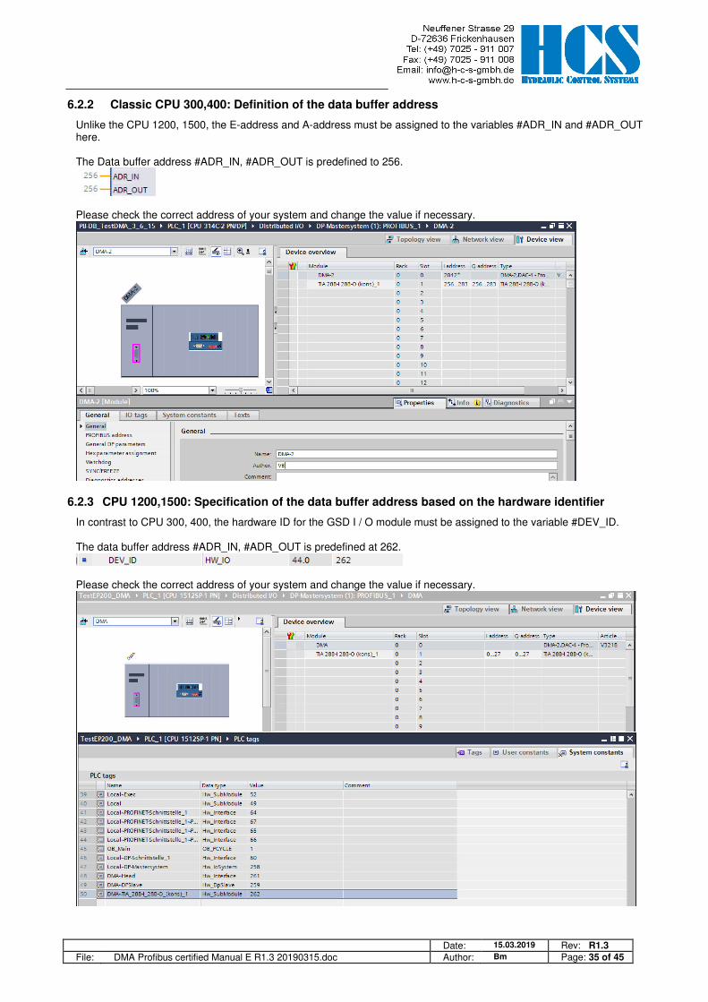
6.2.2 Classic CPU 300,400: Definition of the data buffer address ......................................................................... 35
6.2.3 CPU 1200,1500: Specification of the data buffer address based on the hardware identifier ........................ 35
6.2.4 CMD 3, Reading values from one DMA-2 node ............................................................................................ 36
6.2.5 CMD 6, Writing Parameters to one DMA-2 node ......................................................................................... 37
6.2.6 CMD 15, Writing and Reading once to all connected DMA nodes ................................................................ 38
7 List of parameters ....................................................................................................................................................... 39
8 Troubleshooting .......................................................................................................................................................... 45
8.1 General ................................................................................................................................................................ 45
8.2 No profibus communication is possible ................................................................................................................ 45
8.3 Communication ok, but current outputs are inactive ............................................................................................ 45

Date: 15.03.2019 Rev: R1.3 File: DMA Profibus certified Manual E R1.3 20190315.doc Author: Bm Page: 3 of 45
1 Features • Supports Profibus-DP Slave in accordance with IEC 61158 • Supports Profibus DPV1 • Maximum 244 Byte input and 244 Byte output data • Supports up to 12 Mbaud (auto detect) • Electrical isolated and opto-decoupled • Certified by PNO
1.1 Used GSD File
„HCS0EA7.GSD“
1.2 Supported DMA SW-versions
Version: V15.xxy, open loop, one valve with two solenoids. Version: V22.xxy, open loop, two valves with one solenoid each. Version: V31.xxy, Clamp Force Controller see separate document. Version: V32.xxy, closed loop, Mode 3,4,6,8. Version: V72.xxy, closed loop for servo valves, Mode 3,4

Date: 15.03.2019 Rev: R1.3 File: DMA Profibus certified Manual E R1.3 20190315.doc Author: Bm Page: 4 of 45
1.3 PNO Certificate

Date: 15.03.2019 Rev: R1.3 File: DMA Profibus certified Manual E R1.3 20190315.doc Author: Bm Page: 5 of 45
1.4 Special information for Multi-Slave Nodes
In cases where a Profibus node has more than one slave (modules) connected all slaves must be active (connected to the power supply). The hardware enable is connected to all of the DMA modules. Other wise communication is not possible and the node-module will respond with a timeout error message. The Profibus Address Selector in front of the Profibus-Node is set to the right value (bus error LED is off). If 3 modules are used then E22 must be set to „1“ for the first module on the left, to „2“ for the second module in the middle and to „3“ for the third module closest to the slave.
1.5 General information about TADR (Telegram Address)
TADR is a value which may be written (changed) with each cycle but changing of this value is optional and not mandatory. The value will be defined by the DP-Master. The purpose is to either check the telegrams by the master or also in order to force sending of a new telegram from the node. The design of the node is made in a way that the slave or slaves (module or modules in case of multi-slave version) are only responding if a received message from the master contains changed (different) data compared to the previous message. So TADR can be used to force a response from a slave for example in order to get an update on the current status of the slave even if the other data in the message remain unchanged. TADR value is valid in the range of 0 to 255 or in hexadecimal 0x00 to 0xFF.
1.6 General information about CMD (Command) and SADR (Slave Address)
Different ways of communication between master and slaves (modules) are possible. The difference is in the CMD instruction.
CMD = 6: Writing of a single parameter-ID of a slave (module) at a node. The selected SADR in the telegram will define which slave is selected fort he communication. In the slave itself the address is set by parameter E22, Special case: the Profibus node has only one slave (module) connected. In this case SADR is set to 1 (defined in parameter E22). SADR also could be set to any value between 1 and 32. Theoretically up to 32 slaves (modules) can be connected to one of the Profibus nodes. Which of the slaves (modules) is selected for communication is again defined in the telegram by the SADR and in the slaves (modules) by setting of parameter E22. For more information please refer to section 3.4.
CMD = 3: Reading of one ore more parameters with parameter-ID in rising order. All other definitions from CMD = 6 are also applicable. For more information please refer to section 3.1.
CMD = 15: This instruction allows writing or reading of a (pre-defined) set of parameters. The set of parameters itself is depending on the software version of the slaves (modules); refer also to section 4.5. With this instruction all slaves (modules) at a given node with the SADR from 1 to 5 can be reached. This instruction can not be used for slaves (modules) with a SADR > 5. In this case CMD = 3 and CMD = 6 must be used! The best is to set SADR at the slaves in rising and consecutive order beginning with SADR =1 (E22 = 1). In the telegram itself the number of slaves (modules) at the node is defined by SNUM. This at the same time will also define the length of the telegram itself (number of bytes in the telegram). For more information please refer to section 4.
It is possible to „mix“ the instructions CMD = 3, CMD = 6 and CM = 15 for one node. So for example the slaves (modules) with E22 =1, E22 = 2 and E22 = 3 are actuated by CMD =15 and/or CMD = 3 and/or CMD =6, But another slave (module) with address E22 greater than 5 is only actuated either by CMD =3 or CMD = 6.

Date: 15.03.2019 Rev: R1.3 File: DMA Profibus certified Manual E R1.3 20190315.doc Author: Bm Page: 6 of 45
2 Front View: Address Selection and Connectors
2.1 Front View: Single Module Version (node with one module connected)
Example for module in version DMA-22-M1-01-x!
Status LED’s: PW = Power EN = Enable ER = Error
RJ45 Connector: RS232 Interface Pin 1 is the top most terminal Pin 2 = TxD Pin 3 = RxD Pin 7 = GND
Connector X1: 1 = Solenoid A 2 = Solenoid A 3 = Solenoid B 4 = Solenoid B
Connector X2: 1 = Set Point 1 2 = Set Point 2 3 = Set Point 3 4 = Set Point 4
Connector X3: 1 = Enable 2 = Error 3 = Set Point 6 (+) 4 = Set Point 6 (-)
Connector X4: 1 = 0 V ext. 2 = 24 V ext. 3 = 0 V (Ub) 4 = 24 V (Ub)
Address Selector: 1 = Bit 1 2 = Bit 2 3 = Bit 3 4 = Bit 4 5 = Bit 5 6 = Bit 6 7 = Bit 7 8 = not used Example: On = 1, 2, 3, 4 � Address = 15
Status LED Profibus DP: Red = not connected or Error Off = OK
Connector Profibus DP: 1 = N/C 2 = N/C 3 = PB+ 4 = PB-RTS 5 = PB-GND 6 = PB-5 V 7 = N/C 8 = PB- 9 = N/C
Connector Profibus DP: Pin 1

Date: 15.03.2019 Rev: R1.3 File: DMA Profibus certified Manual E R1.3 20190315.doc Author: Bm Page: 7 of 45
2.2 Front View: Multiple-Slave Version (node with multiple modules connected)
Example: 1 Profibus-Node and 3 DMA Modules (Slaves) connected
Slave 1 to 3 (Module 1 to 3)
Profibus-Node
Example: Defined Slave SADR = 1 (E22 = 1)
Example: Defined Slave SADR = 3 (E22 = 3)
Example: Defined Slave SADR = 2 (E22 = 2)

Date: 15.03.2019 Rev: R1.3 File: DMA Profibus certified Manual E R1.3 20190315.doc Author: Bm Page: 8 of 45
3 Simple commands
3.1 CMD = 3, Master Read parameters (7 bytes)
Write first…
Byte Abbreviation Description 0 TADR Telegram address, defined by the user, Range 0..255, 0..0xFF 1 SADR Slave address 2 CMD Command: 3 = Read multiple parameters by the master 3 IDH High byte parameter ID of first parameter 4 IDL Low byte parameter ID of first parameter 5 N-high High-Byte Number parameters 6 N-low Low-Byte Number parameters
…Write last
TADR Telegram address, defined by the DP-Master.( Set by the User )
SADR Slave address, if more than one Slave is connected to the Profibus port 1 = standard (single slave) 2 to 32 = also possible (E22 defines the slave address)
CMD Command: 3 = Read parameter by the master
IDH,IDL H-Byte and Low-Byte of parameter-ID in HEX 0x0000 .. 0x00A2 = Valid ID-range
N-high High-Byte Number parameters (words), normally zero
N-low Low-Byte Number parameters (words), 1 to 8 (0x08) (maximal 8 parameters readable at once)
3.2 CMD = 3, Response from Slave (4 + CNT bytes)
Write first…
Byte Abbreviation Description 0 TADR Telegram address, defined by the read command, Range 0..255, 0..0xFF 1 SADR Slave address 2 CMD Command: 3 = Read multiple parameters by the master 3 CNT N*2, Number of data bytes 4 DAT1H High byte value of first parameter 5 DAT1L Low Byte value of first parameter
If CNT > 2: …… CNT+2 = N DATnH High byte value of last (n)parameter CNT+3 = N DATnL Low Byte value of last (n)parameter
…Write last
TADR Telegram address, defined by the DP-Master. (Set by the read command)
SADR Slave address, if more than one Slave is connected to the Profibus port 1 = standard (single slave) 2 to 32 = also possible (E22 defines the slave address)
CMD Command: 3 = Read parameter by the master
CNT N*2, Number of data bytes (Maximal 16 data bytes)
IDH,IDL H-Byte and Low-Byte of parameter-ID in HEX 0x0000 .. 0x00B0 = Valid ID-Range
DAT1H.. DAT nH, DAT1L.. DAT nL, Two data bytes in HEX, without decimal sign 0x7FFF == +32767 0x8000 == -32768

Date: 15.03.2019 Rev: R1.3 File: DMA Profibus certified Manual E R1.3 20190315.doc Author: Bm Page: 9 of 45
3.3 CMD = 3, Error from Slave (4 bytes)
Write first…
Byte Abbreviation Description 0 TADR Telegram address, defined by the read command, Range 0..255, 0..0xFF 1 SADR Slave address 2 ERR Error code 3 EXCE Exception
…Write last
ERR Error code: 0x83 = Read failed
EXCE Exception: 1 = Command not supported 2 = Wrong ID 3 = CNT== 0 or CNT > 16 (0x10) 4 = Reading of ID failed
5 = timeout slave, address wrong or not installed or Invalid number of connected slaves
6 = Internal checksum error (Modbus)
Example for error response: Module 3 is not installed and SADR in the master telegram is set to 3
Byte Abbreviation Abbreviation Description 0 0x23 TADR Response telegram address (defined by the read command) 1 0x03 SADR Actual slave address 2 0x83 ERR Error, Bit „7“ with command 0x03 is set 3 0x05 EXCE timeout slave, address wrong or not installed

Date: 15.03.2019 Rev: R1.3 File: DMA Profibus certified Manual E R1.3 20190315.doc Author: Bm Page: 10 of 45
3.4 CMD = 6, Master Write single parameter (7 bytes)
Write first…
Byte Abbreviation Description 0 TADR Telegram address, defined by the user, Range 0..255, 0..0xFF 1 SADR Slave address 2 CMD Command: 6 = Write single parameter by the master 3 IDH High byte parameter ID 4 IDL Low byte parameter ID 5 DATH High byte of parameter value 6 DATL Low byte of parameter value
…Write last
TADR Telegram address, defined by the DP-Master.(Set by the user)
SADR Slave address, if more than one Slave is connected to the Profibus port 1 = standard (single slave) 2..32 = also possible (E22 defines the slave address)
CMD Command: 6 = Write single parameter by the master
IDH,IDL H-Byte and Low-Byte of parameter-ID in HEX 0x0000 .. 0x00B0 = Valid ID-Range
DATH,DATL Two data bytes in HEX, without decimal sign 0x7FFF == +32767 0x8000 == -32768
3.5 CMD = 6, Response from Slave (7 bytes)
Write first…
Byte Abbreviation Description 0 TADR Telegram address, defined by the write command, Range 0..255, 0..0xFF 1 SADR Slave address 2 CMD Command: 6 = Write single parameter by the master 3 IDH High byte parameter ID 4 IDL Low byte parameter ID 5 DATH High byte of second analogue value 6 DATL Low byte of first analogue value
…Write last
TADR Telegram address, defined by the DP-Master.( Set by the write command )
SADR Slave address, if more than one Slave is connected to the Profibus port 1 = standard (single slave) 2..32 = also possible (E22 defines the slave address)
CMD Command: 6 = Write single parameter by the master IDH,IDL H-Byte and Low-Byte of parameter-ID in HEX
0x0000 .. 0x00A2 Valid ID-Range
DATH,DATL Two data bytes in HEX, without decimal sign 0x7FFF == +32767 0x8000 == -32768

Date: 15.03.2019 Rev: R1.3 File: DMA Profibus certified Manual E R1.3 20190315.doc Author: Bm Page: 11 of 45
3.6 CMD = 6, Error from Slave (4 bytes)
Write first…
Byte Abbreviation Description 0 TADR Telegram address, defined by the write command, Range 0..255, 0..0xFF 1 SADR Slave address 2 ERR Error code 3 EXCE Exception
…Write last
ERR Error code: 0x86 = write failed
EXCE Exception: 1 = Command not supported 2 = Wrong ID 3 = Wrong Data Value 4 = Writing of ID failed
5 = timeout slave, address wrong or not installed or Invalid number of connected slaves
6 = Internal checksum error (Modbus)
Example for error response: Module 3 is not installed and SADR in the master telegram is set to 3
Byte Abbreviation Abbreviation Description 0 0x23 TADR Response telegram address (defined by the write command) 1 0x03 SADR Actual slave address 2 0x86 ERR Error, Bit „7“ with command 0x06 is set 3 0x05 EXCE timeout slave, address wrong or not installed

Date: 15.03.2019 Rev: R1.3 File: DMA Profibus certified Manual E R1.3 20190315.doc Author: Bm Page: 12 of 45
3.7 Telegram example CMD = 6, CMD = 3
Master wants to write parameter “C1.07” with value 1.000 V: ID = 0x0030 DATA = 0x3E8 ( = 1000 in decimal) TADR = 0x23 SADR = 0x01 Byte Value Abbreviation
0 0x23 TADR 1 0x01 SADR 2 0x06 CMD 3 0x00 IDH 4 0x30 IDL 5 0x03 DATL 6 0xE8 DATH
Response from slave (module), command was successful executed ID = 0x0030 DATA = 0x3E8 ( = 1.000 V) Byte Value Abbreviation
0 0x23 TADR 1 0x01 SADR 2 0x06 CMD 3 0x00 IDH 4 0x30 IDL 5 0x03 DATL 6 0xE8 DATH
Master wants to read parameter “d1.07”: ID = 0x0007 N = 1, one parameter TADR = 0x24 SADR = 0x01 Byte Value Abbreviation
0 0x24 TADR 1 0x01 SADR 2 0x03 CMD 3 0x00 IDH 4 0x07 IDL 5 0x00 N-high 6 0x01 N-low
Response from slave (module) CNT = 2 (2 Bytes) DATA = 0x0133 (==0.307Af) Byte Value Abbreviation
0 0x24 TADR 1 0x01 SADR 2 0x03 CMD 3 0x02 CNT 4 0x01 DAT1H 5 0x33 DAT1L
Date: 15.03.2019 Rev: R1.3 File: DMA Profibus certified Manual E R1.3 20190315.doc Author: Bm Page: 13 of 45
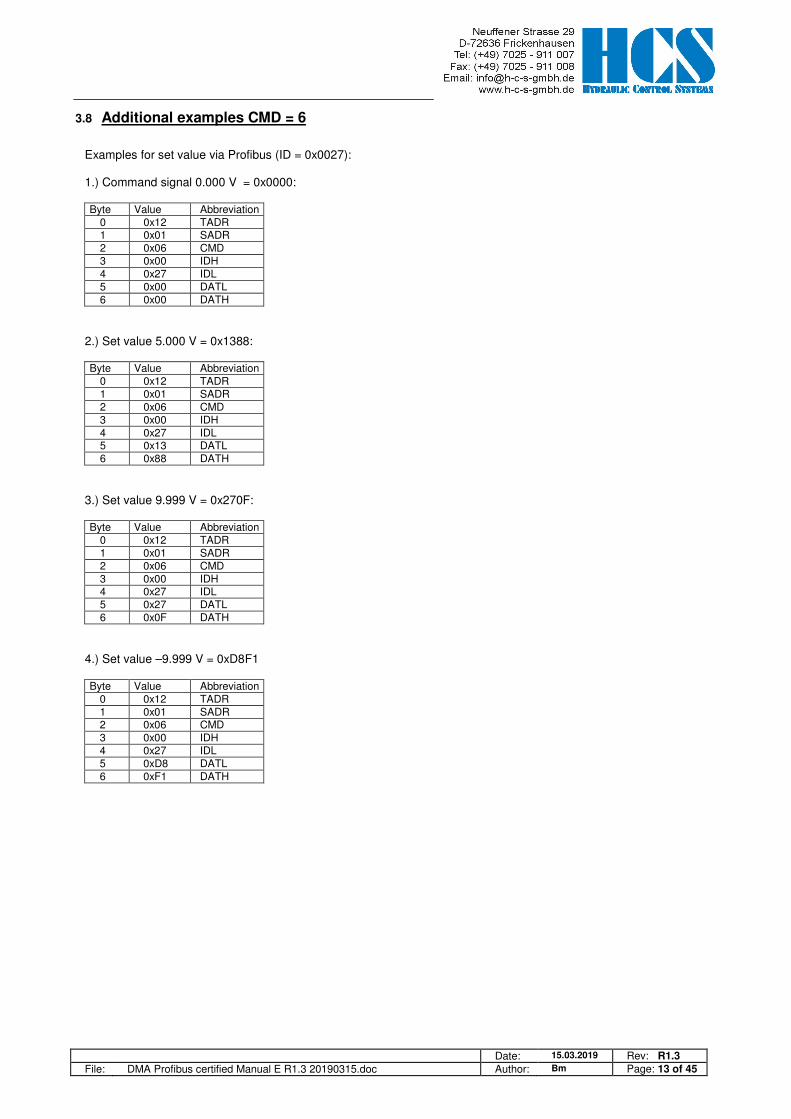
3.8 Additional examples CMD = 6
Examples for set value via Profibus (ID = 0x0027): 1.) Command signal 0.000 V = 0x0000: Byte Value Abbreviation
0 0x12 TADR 1 0x01 SADR 2 0x06 CMD 3 0x00 IDH 4 0x27 IDL 5 0x00 DATL 6 0x00 DATH
2.) Set value 5.000 V = 0x1388: Byte Value Abbreviation
0 0x12 TADR 1 0x01 SADR 2 0x06 CMD 3 0x00 IDH 4 0x27 IDL 5 0x13 DATL 6 0x88 DATH
3.) Set value 9.999 V = 0x270F: Byte Value Abbreviation
0 0x12 TADR 1 0x01 SADR 2 0x06 CMD 3 0x00 IDH 4 0x27 IDL 5 0x27 DATL 6 0x0F DATH
4.) Set value –9.999 V = 0xD8F1 Byte Value Abbreviation
0 0x12 TADR 1 0x01 SADR 2 0x06 CMD 3 0x00 IDH 4 0x27 IDL 5 0xD8 DATL 6 0xF1 DATH

Date: 15.03.2019 Rev: R1.3 File: DMA Profibus certified Manual E R1.3 20190315.doc Author: Bm Page: 14 of 45
4 Complex commands
4.1 CMD = 15, Master writes multiple parameters (3+5·module bytes)
(Fast multi-slave command) Parameter E22 in the related DMA-module has to be set to the correct value within the range of 1 to 5 depending on the number of connected slaves (modules). The slave at the left side has the address “1” and the slave closest to the Profibus node will have the highest address setting. Example: If 3 modules are used than E22 must be set to „1“ for the first module on the left, to „2“ for the second module in the middle and to „3“ for the third module closest to the slave (refer also to 2.2). Response telegrams are automatically multiplexed by the Profibus node (refer also to 4.4.2).
Write first…
address Byte Structure Abbreviation Description 0 0..0xFF TADR Telegram address, defined by the user, Range 0..255, 0..0xFF 1 1 2 3 4 5 SNUM Number of connected slaves (Maximum 5) 2 15 CMD Command: 15 = Write multiple parameter by the master
3
1 1 1 1 1
DAT1.1 Control-Byte Byte for special functions 4 DAT1.2H
Process Value1 High byte of first “analogue” value
5 DAT1.2L Low byte of first “analogue” value 6 DAT1.3H
Process Value2 High byte of second “analogue” value
7 DAT1.3L Low byte of second “analogue” value
8
2 2 2 2
DAT1.1 Control-Byte Byte for special functions 9 DAT1.2H
Process Value1 High byte of first “analogue” value
10 DAT1.2L Low byte of first “analogue” value 11 DAT1.3H
Process Value2 High byte of second “analogue” value
12 DAT1.3L Low byte of second “analogue” value
13
3 3 3
DAT3.1 Control-Byte Byte for special functions 14 DAT3.2H
Process Value1 High byte of first “analogue” value
15 DAT3.2L Low byte of first “analogue” value 16 DAT3.3H
Process Value2 High byte of second “analogue” value
17 DAT3.3L Low byte of second “analogue” value
18
4 4
DAT4.1 Control-Byte Byte for special functions 19 DAT4.2H
Process Value1 High byte of first “analogue” value
20 DAT4.2L Low byte of first “analogue” value 21 DAT4.3H
Process Value2 High byte of second “analogue” value
22 DAT4.3L Low byte of second “analogue” value
23
5
DAT5.1 Control-Byte Byte for special functions 24 DAT5.2H
Process Value1 High byte of first “analogue” value
25 DAT5.2L Low byte of first “analogue” value 26 DAT5.3H
Process Value2 High byte of second “analogue” value
27 DAT5.3L Low byte of second “analogue” value ….Write last 8 13 18 23 28 Overall telegram length in bytes
TADR Telegram address, defined by the DP-Master. (defined by the user) Range 0..255
SNUM Number of connected slaves (Maximum 5). Here for multi slave operation the number of present slaves has to be set properly.
CMD Command: 15 = Write multiple parameters by the master
DATx1).1 Control-Byte. One data byte in HEX, for special functions
0x00 == 0 0xFF == 255
DATx1).2H, DATx
1).2L Process Value1: Two data bytes in HEX, without decimal sign, for “analogue” values
0x7FFF == +32767 0x8000 == -32768
DATx1).3H, DATx
1).3L Process Value1: Two data bytes in HEX, without decimal sign, for “analogue” values
0x7FFF == +32767 0x8000 == -32768
x
1).= Module address (set by parameter E22 in each DMA-Module) range 1 to 5.
Date: 15.03.2019 Rev: R1.3 File: DMA Profibus certified Manual E R1.3 20190315.doc Author: Bm Page: 15 of 45
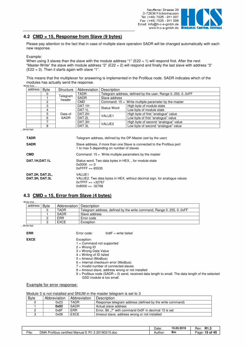
4.2 CMD = 15, Response from Slave (9 bytes)
Please pay attention to the fact that in case of multiple slave operation SADR will be changed automatically with each new response. Example: When using 3 slaves than the slave with the module address “1” (E22 = 1) will respond first. After the next “Master-Write” the slave with module address “2” (E22 = 2) will respond and finally the last slave with address “3” (E22 = 3). Then it starts again with slave “1”. This means that the multiplexer for answering is implemented in the Profibus node. SADR indicates which of the modules has actually send the response.
Write first…
address Byte Structure Abbreviation Description 0
Telegram header
TADR Telegram address, defined by the user, Range 0..255, 0..0xFF 1 SADR Slave address 2 CMD Command: 15 = Write multiple parameter by the master 3
Data of SADR
DAT.1H Status Word
High byte of module state 4 DAT.1L Low byte of module state 5 DAT.2H
VALUE1 High byte of first “analogue” value
6 DAT.2L Low byte of first “analogue” value 7 DAT.3H
VALUE2 High byte of second “analogue” value
8 DAT.3L Low byte of second “analogue” value …Write last
TADR Telegram address, defined by the DP-Master.(set by the user)
SADR Slave address, if more than one Slave is connected to the Profibus port 1 to max 5 depending on number of slaves
CMD Command: 15 = Write multiple parameters by the master
DAT.1H,DAT.1L Status word. Two data bytes in HEX, , for module state 0x0000 == 0 0xFFFF == 65535
DAT.2H, DAT.2L, VALUE1 DAT.3H, DAT.3L VALUE2. Two data bytes in HEX, without decimal sign, for analogue values 0x7FFF == +32767 0x8000 == -32768
4.3 CMD = 15, Error from Slave (4 bytes)
Write first…
address Byte Abbreviation Description 0 TADR Telegram address, defined by the write command, Range 0..255, 0..0xFF 1 SADR Slave address 2 ERR Error code 3 EXCE Exception
…Write last
ERR Error code: 0x8F = write failed
EXCE Exception: 1 = Command not supported 2 = Wrong ID 3 = Wrong Data Value 4 = Writing of ID failed 5 = timeout (Modbus) 6 = Internal checksum error (Modbus) 7 = Invalid number of connected slaves 8 = timeout slave, address wrong or not installed
9 = Profibus node (SADR = 0) send, received data length to small. The data length of the selected GSD module is too small.
Example for error response: Module 3 is not installed and SNUM in the master telegram is set to 3 Byte Abbreviation Abbreviation Description
0 0x23 TADR Response telegram address (defined by the write command) 1 0x03 SADR Actual slave address 2 0x8F ERR Error, Bit „7“ with command 0x0F in decimal 15 is set 3 0x08 EXCE timeout slave, address wrong or not installed

Date: 15.03.2019 Rev: R1.3 File: DMA Profibus certified Manual E R1.3 20190315.doc Author: Bm Page: 16 of 45
4.4 Examples, CMD = 15
4.4.1 Single slave (SW Version 15.xxy)
The Profibus Address Selector in front of the Profibus-Node is set to the right value (bus error LED is off). E22 of the DMA module is set to 1. Hardware Enable is connected to the DMA module. Master writes set value of 1.000 V to slave (module):
Byte Abbreviation Abbreviation Description 0 0x23 TADR Telegram address, defined by the user, Range 0..255, 0..0xFF 1 0x01 SNUM 0x01 means single slave 2 0x0F CMD 0x0F in decimal 15 3 0x00 DAT1.1 Byte for special functions , 0x00 (default value, no bus-disable) 4
(1000) DAT1.2H Set Value A1.01
0x03E8 ( = 1000 in decimal = 1.000V) 5 DAT1.2L 6
(0) DAT1.3H Set Value A1.02
0x0000 ( = 0 in decimal = 0.000V) 7 DAT1.3L
Response slave (module) no.1:
Byte Abbreviation Abbreviation Description 0 0x23 TADR Response telegram address (defined by the write command) 1 0x01 SADR Actual slave address 2 0x0F CMD 0x0F in decimal 15 3 0x40 DAT1.1H High byte of module state, Hardware Enable is active, no error 4 0x00 DAT1.1L Low byte of module state, not used, in this case always zero 5
(0) DAT1.2H Actual current A
0x0000 ( = 0 in decimal = 0.000A ) 6 DAT1.2L 7
(270) DAT1.3H Actual current B
0x010E ( = 270 in decimal = 0.270A ) 8 DAT1.3L (x) = value in decimal.
4.4.2 Multiple-slave (3 DMA modules, SW Version 15.xxy)
The Profibus Address Selector in front of the Profibus-Node is set to the right value (bus error LED is off). E22 of the three modules is set to 1, 2, 3. All modules are powered on, hardware enable is connected all of the DMA modules. Master first write cycle: set value 1.000 V to slave1, 2.000 V to slave2 and - 3.000 V to slave3:
Byte Abbreviation Abbreviation Description 0 0x23 TADR Telegram address, defined by the user, Range 0..255, 0..0xFF 1 0x03 SNUM 0x03 means three slaves (modules) are connected 2 0x0F CMD 0x0F in decimal 15 3 0x00 DAT1.1 Byte for special functions, 0x00 (default value, no bus-disable) 4
(1000) DAT1.2H Set Value A1.01
0x03E8 ( = 1000 in decimal = 1.000V) 5 DAT1.2L 6
(0) DAT1.3H Set Value A1.02
0x0000 ( = 0 in decimal = 0.000V) 7 DAT1.3L 8 0x00 DAT2.1 Byte for special functions, 0x00 (default value, no bus-disable) 9
(2000) DAT2.2H Set Value A1.01
0x07D0 ( = 2000 in decimal = 2.000V) 10 DAT2.2L 11
(0) DAT2.3H Set Value A1.02
0x0000 ( = 0 in decimal = 0.000V) 12 DAT2.3L 13 0x00 DAT3.1 Byte for special functions, 0x00 (default value, no bus-disable) 14
(-3000) DAT3.2H Set Value A1.01
0xF448 ( = - 3000 in decimal = - 3.000V) 15 DAT3.2L 16
(0) DAT3.3H Set Value A1.02
0x0000 ( = 0 in decimal = 0.000V) 17 DAT3.3L (x) = value in decimal.
The node will only send a response if any data in the telegram received from the master has be changed! If the data in a telegram have to remain unchanged than a response from the node to a ”Master write” can be enforced due to a change of the data TADR. The data of the write command will be immediately forwarded to all slaves (modules). Each response telegram to a write command will automatically contain “new data” from the next slave (module). The slaves are automatically multiplexed.

Date: 15.03.2019 Rev: R1.3 File: DMA Profibus certified Manual E R1.3 20190315.doc Author: Bm Page: 17 of 45
Response telegrams are automatically multiplexed by the DMA-Profibus node. In this example, module 1 answers first Byte Abbreviation Abbreviation Description
0 0x23 TADR Response telegram address (defined by the write command) 1 0x01 SADR Actual slave address 2 0x0F CMD 0x0F in decimal 15 3 0x40 DAT1.1H High byte of module state, Hardware Enable is active, no error 3 0x00 DAT1.1L Low byte of module state, not used, in this case always zero 4
(0) DAT1.2H Actual current A, d1.07 of module 1
0x0000 ( = 0 in decimal = 0.000A ) 5 DAT1.2L 6
(270) DAT1.3H Actual current B, d1.08 of module 1
0x010E ( = 270 in decimal = 0.270A ) 7 DAT1.3L (x) = value in decimal. Change telegram address TADR to 0x24 and send same message as before. Next module no. 2 will answer. Byte Abbreviation Abbreviation Description
0 0x24 TADR Response telegram address (defined by the write command) 1 0x02 SADR Actual slave address 2 0x0F CMD 0x0F in decimal 15 3 0x40 DAT1.1H High byte of module state, Hardware Enable is active, no error 3 0x00 DAT1.1L Low byte of module state, not used, in this case always zero 4
(0) DAT1.2H Actual current A, d1.07 of module 2
0x0000 ( = 0 in decimal = 0.000A ) 5 DAT1.2L 6
(540) DAT1.3H Actual current B, d1.08 of module 2
0x021C ( = 540 in decimal = 0.540A ) 7 DAT1.3L (x) = value in decimal. Change telegram address TADR to 0x25 and send same message as before. Next module no. 3 will answer. Byte Abbreviation Abbreviation Description
0 0x25 TADR Response telegram address (defined by the write command) 1 0x03 SADR Actual slave address 2 0x0F CMD 0x0F in decimal 15 3 0x40 DAT1.1H High byte of module state, Hardware Enable is active, no error 3 0x00 DAT1.1L Low byte of module state, not used, in this case always zero 4
(810) DAT1.2H Actual current A, d1.07 of module 3
0x032A ( = 810 in decimal = 0.810A ) 5 DAT1.2L 6
(0) DAT1.3H Actual current B, d1.08 of module 3
0x0000 ( = 0 in decimal = 0.000A ) 7 DAT1.3L (x) = value in decimal. Change telegram address TADR to 0x26 and send same message as before. Next module no. 1 will answer. Byte Abbreviation Abbreviation Description
0 0x26 TADR Response telegram address (defined by the write command) 1 0x01 SADR Actual slave address 2 0x0F CMD 0x0F in decimal 15 3 0x40 DAT1.1H High byte of module state, Hardware Enable is active, no error 3 0x00 DAT1.1L Low byte of module state, not used, in this case always zero 4
(0) DAT1.2H Actual current A, d1.07 of module 1
0x000 ( = 0 in decimal = 0.000A) 5 DAT1.2L 6
(270) DAT1.3H Actual current B, d1.08 of module 1
0x10E ( = 270 in decimal = 0.270A) 7 DAT1.3L (x) = value in decimal.
Date: 15.03.2019 Rev: R1.3 File: DMA Profibus certified Manual E R1.3 20190315.doc Author: Bm Page: 18 of 45
4.5 CMD = 15, structure of Profibus telegram definition, depending on SW Versions
4.5.1 General
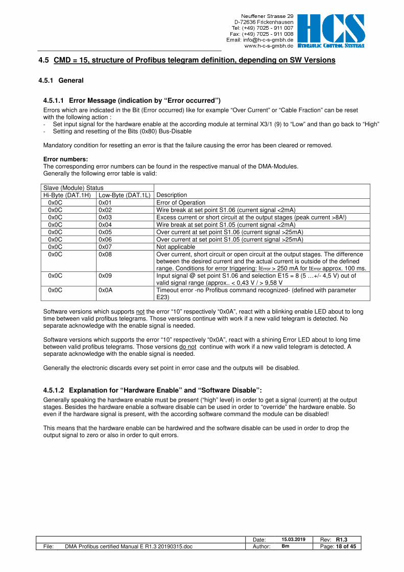
4.5.1.1 Error Message (indication by “Error occurred”)
Errors which are indicated in the Bit (Error occurred) like for example “Over Current” or “Cable Fraction” can be reset with the following action : - Set input signal for the hardware enable at the according module at terminal X3/1 (9) to “Low” and than go back to “High” - Setting and resetting of the Bits (0x80) Bus-Disable Mandatory condition for resetting an error is that the failure causing the error has been cleared or removed. Error numbers: The corresponding error numbers can be found in the respective manual of the DMA-Modules. Generally the following error table is valid: Slave (Module) Status
Description Hi-Byte (DAT.1H) Low-Byte (DAT.1L) 0x0C 0x01 Error of Operation 0x0C 0x02 Wire break at set point S1.06 (current signal <2mA) 0x0C 0x03 Excess current or short circuit at the output stages (peak current >8A!) 0x0C 0x04 Wire break at set point S1.05 (current signal <2mA) 0x0C 0x05 Over current at set point S1.06 (current signal >25mA) 0x0C 0x06 Over current at set point S1.05 (current signal >25mA) 0x0C 0x07 Not applicable 0x0C 0x08 Over current, short circuit or open circuit at the output stages. The difference
between the desired current and the actual current is outside of the defined range. Conditions for error triggering: IError > 250 mA for tError approx. 100 ms.
0x0C 0x09 Input signal @ set point S1.06 and selection E15 = 8 (5 …+/- 4,5 V) out of valid signal range (approx.. < 0,43 V / > 9,58 V
0x0C 0x0A Timeout error -no Profibus command recognized- (defined with parameter E23)
Software versions which supports not the error “10” respectively “0x0A”, react with a blinking enable LED about to long time between valid profibus telegrams. Those versions continue with work if a new valid telegram is detected. No separate acknowledge with the enable signal is needed. Software versions which supports the error “10” respectively “0x0A”, react with a shining Error LED about to long time between valid profibus telegrams. Those versions do not continue with work if a new valid telegram is detected. A separate acknowledge with the enable signal is needed. Generally the electronic discards every set point in error case and the outputs will be disabled.
4.5.1.2 Explanation for “Hardware Enable” and “Software Disable”:
Generally speaking the hardware enable must be present (“high” level) in order to get a signal (current) at the output stages. Besides the hardware enable a software disable can be used in order to “override” the hardware enable. So even if the hardware signal is present, with the according software command the module can be disabled! This means that the hardware enable can be hardwired and the software disable can be used in order to drop the output signal to zero or also in order to quit errors.

Date: 15.03.2019 Rev: R1.3 File: DMA Profibus certified Manual E R1.3 20190315.doc Author: Bm Page: 19 of 45
4.5.1.3 Explanation of special functions and module state bits
Attention: Functions and module state bits depend on the used SW version HW_ENABLE The signal ”D-In Enable” (HW Enable) is activated at the module. ERROR An Error has occurred in the DMA module. Different possible problems can cause this. Please refer to the
manual for the according DMA version BUS_DISABLE The Enable signal was reset by means of Profibus (DMA module is disabled). Din_1 The “enable function” for the „remote loop controller“ (function switches from open loop to closed loop) via the
comparator „KOMP_1“ is enabled and can be used. Additional mandatory condition: C1.00 must be set to 2 or 4! Remark: d1.12 and d1.13 remain at „0.000 V“ as long as the condition for activation „Din_1“ has not be set. This will prevent a premature activation of the comparator „KOMP_1“.
Dout_1 Indicates that the function „remote loop controller“ is active. The module is now working in closed loop mode. Additional mandatory conditions for transition from open loop to closed loop: C1.00 must be set to 2 or 4 Signal Din_1 must be present Comparator KOMP_1 has to be outside of the window, hence signal KOMP_1 = 0. The module will remain in closed loop operation as long as signal Din_1 stays on “High”.
DKOMP_1 Output signal of comparator „KOMP_1“, s used in order to monitor the signal defined by C1.25. This signal can also be used in order to switches over from open to closed loop: 0 = comparator is not active (out of the determined limits and time delays) 1 = comparator is active (inside the determined limits and time delays).
DKOMP_11 Output signal of comparator „KOMP_11“, is used in order to monitor the signal defined by C1.32 0 = comparator is not active (out of the determined limits and time delays) 1 = comparator is active (inside the determined limits and time delays).
Din_2 The “enable function” for the „remote loop controller“ (function switches from open loop to closed loop) via the comparator „KOMP_2“ is enabled and can be used. Additional mandatory condition: C2.00 must be set to 2 or 4! Remark: d2.12 and d2.13 remain at „0.000 V“ as long as the condition for activation „Din_2“ has not be set. This will prevent a premature activation of the comparator „KOMP_2“..
Dout_2 Indicates that the function „remote loop controller“ is active. The module is now working in closed loop mode. Additional mandatory conditions for transition from open loop to closed loop: C2.00 must be set to 2 or 4 Signal Din_2 must be present Comparator KOMP_2 has to be outside of the window, hence signal KOMP_2 = 0. The module will remain in closed loop operation as long as signal Din_2 stays on “High”.
DKOMP_2 Output signal of comparator „KOMP_2“, s used in order to monitor the signal defined by C2.25. This signal can also be used in order to switches over from open to closed loop: 0 = comparator is not active (out of the determined limits and time delays) 1 = comparator is active (inside the determined limits and time delays).
DKOMP_22 Output signal of comparator „KOMP_22“, is used in order to monitor the signal defined by C2.32 0 = comparator is not active (out of the determined limits and time delays) 1 = comparator is active (inside the determined limits and time delays).
TST_CMP Set Error/Comp output direct to 24V (disable signalizing of error output). Used to test the comparator or fault output. CNTRL_1..4 Reserved for special functions STAT_1..5 Reserved for special functions
Date: 15.03.2019 Rev: R1.3 File: DMA Profibus certified Manual E R1.3 20190315.doc Author: Bm Page: 20 of 45
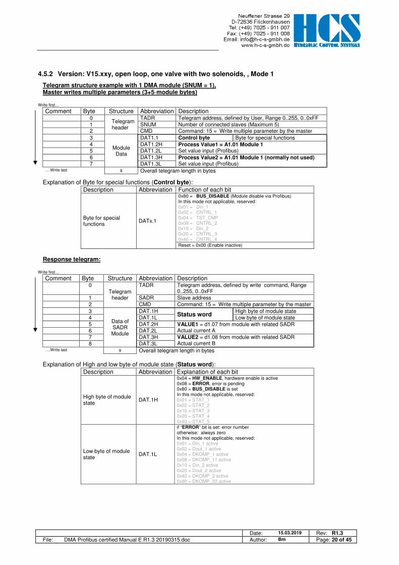
4.5.2 Version: V15.xxy, open loop, one valve with two solenoids, , Mode 1
Telegram structure example with 1 DMA module (SNUM = 1), Master writes multiple parameters (3+5·module bytes)
Write first…
Comment Byte Structure Abbreviation Description 0
Telegram header
TADR Telegram address, defined by User, Range 0..255, 0..0xFF 1 SNUM Number of connected slaves (Maximum 5) 2 CMD Command: 15 = Write multiple parameter by the master
3
Module Data
DAT1.1 Control byte Byte for special functions 4 DAT1.2H Process Value1 = A1.01 Module 1
Set value input (Profibus) 5 DAT1.2L 6 DAT1.3H Process Value2 = A1.01 Module 1 (normally not used)
Set value input (Profibus) 7 DAT1.3L ….Write last 8 Overall telegram length in bytes
Explanation of Byte for special functions (Control byte): Description Abbreviation Function of each bit
Byte for special functions
DATx.1
0x80 = BUS_DISABLE (Module disable via Profibus) In this mode not applicable, reserved: 0x01 = Din_1 0x02 = CNTRL_1 0x04 = TST_CMP 0x08 = CNTRL_2 0x10 = Din_2 0x20 = CNTRL_3 0x40 = CNTRL_4 Reset = 0x00 (Enable inactive)
Response telegram:
Write first…
Comment Byte Structure Abbreviation Description 0
Telegram header
TADR Telegram address, defined by write command, Range 0..255, 0..0xFF
1 SADR Slave address 2 CMD Command: 15 = Write multiple parameter by the master
3
Data of SADR Module
DAT.1H Status word
High byte of module state 4 DAT.1L Low byte of module state 5 DAT.2H VALUE1 = d1.07 from module with related SADR
Actual current A 6 DAT.2L 7 DAT.3H VALUE2 = d1.08 from module with related SADR
Actual current B 8 DAT.3L ….Write last 9 Overall telegram length in bytes
Explanation of High and low byte of module state (Status word):
Description Abbreviation Explanation of each bit
High byte of module state
DAT.1H
0x04 = HW_ENABLE, hardware enable is active 0x08 = ERROR, error is pending 0x80 = BUS_DISABLE is set In this mode not applicable, reserved: 0x01 = STAT_1 0x02 = STAT_2 0x10 = STAT_3 0x20 = STAT_4 0x40 = STAT_5
Low byte of module state
DAT.1L
if “ERROR” bit is set: error number otherwise: always zero In this mode not applicable, reserved: 0x01 = Din_1 active 0x02 = Dout_1 active 0x04 = DKOMP_1 active 0x08 = DKOMP_11 active 0x10 = Din_2 active 0x20 = Dout_2 active 0x40 = DKOMP_2 active 0x80 = DKOMP_22 active
Date: 15.03.2019 Rev: R1.3 File: DMA Profibus certified Manual E R1.3 20190315.doc Author: Bm Page: 21 of 45
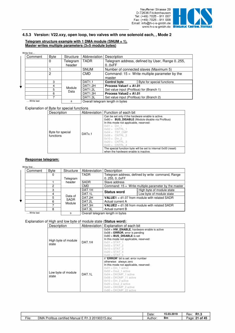
4.5.3 Version: V22.xxy, open loop, two valves with one solenoid each, , Mode 2
Telegram structure example with 1 DMA module (SNUM = 1), Master writes multiple parameters (3+5·module bytes)
Write first…
Comment Byte Structure Abbreviation Description 0 Telegram
header TADR Telegram address, defined by User, Range 0..255,
0..0xFF 1 SNUM Number of connected slaves (Maximum 5) 2 CMD Command: 15 = Write multiple parameter by the
master 3
Module Data
DAT1.1 Control byte Byte for special functions 4 DAT1.2H Process Value1 = A1.01
Set value input (Profibus) for (Branch 1) 5 DAT1.2L 6 DAT1.3H Process Value2 = A1.01
Set value input (Profibus) for (Branch 2) 7 DAT1.3L ….Write last 8 Overall telegram length in bytes
Explanation of Byte for special functions Description Abbreviation Function of each bit
Byte for special functions
DATx.1
Can be set only if the hardware enable is active. 0x80 = BUS_DISABLE (Module disable via Profibus) In this mode not applicable, reserved: 0x01 = Din_1 0x02 = CNTRL_1 0x04 = TST_CMP 0x08 = CNTRL_2 0x10 = Din_2 0x20 = CNTRL_3 0x40 = CNTRL_4 The special function byte will be set to internal 0x00 (reset) when the hardware enable is inactive.
Response telegram:
Write first…
Comment Byte Structure Abbreviation Description 0
Telegram header
TADR Telegram address, defined by write command, Range 0..255, 0..0xFF
1 SADR Slave address 2 CMD Command: 15 = Write multiple parameter by the master
3
Data of SADR Module
DAT.1H Status word
High byte of module state 4 DAT.1L Low byte of module state 5 DAT.2H VALUE1 = d1.07 from module with related SADR
Actual current A 6 DAT.2L 7 DAT.3H VALUE2 = d1.08 from module with related SADR
Actual current B 8 DAT.3L ….Write last 9 Overall telegram length in bytes
Explanation of High and low byte of module state (Status word):
Description Abbreviation Explanation of each bit
High byte of module state
DAT.1H
0x04 = HW_ENABLE, hardware enable is active 0x08 = ERROR, error is pending 0x80 = BUS_DISABLE is set In this mode not applicable, reserved: 0x01 = STAT_1 0x02 = STAT_2 0x10 = STAT_3 0x20 = STAT_4 0x40 = STAT_5
Low byte of module state
DAT.1L
if “ERROR” bit is set: error number otherwise: always zero In this mode not applicable, reserved: 0x01 = Din_1 active 0x02 = Dout_1 active 0x04 = DKOMP_1 active 0x08 = DKOMP_11 active 0x10 = Din_2 active 0x20 = Dout_2 active 0x40 = DKOMP_2 active 0x80 = DKOMP_22 active

Date: 15.03.2019 Rev: R1.3 File: DMA Profibus certified Manual E R1.3 20190315.doc Author: Bm Page: 22 of 45
4.5.4 Version: V32.xxy, V72.xxy, closed loop, Mode 3, 4
Telegram structure example with 1 DMA module (SNUM = 1), Master writes multiple parameters (3+5·module bytes)
Write first…
Comment Byte Structure Abbreviation Description 0 Telegram
header TADR Telegram address, defined by User, Range 0..255,
0..0xFF 1 SNUM Number of connected slaves (Maximum 5) 2 CMD Command: 15 = Write multiple parameter by the
master 3
Module Data
DAT1.1 Control byte Byte for special functions 4 DAT1.2H Process Value1 = A1.01
Set value input (Profibus) for (Branch 1) 5 DAT1.2L 6 DAT1.3H Process Value2 = A1.02
Feedback value input (Profibus) for (Branch 1) 7 DAT1.3L ….Write last 8 Overall telegram length in bytes
Explanation of Byte for special functions (Control byte) Description Abbreviation Function of each bit
Byte for special functions
DATx.1
Can be set only if the hardware enable is active. 0x01 = Din_1; Set signal Din_1 to active 0x04 = TST_CMP; Set Error/Comp output direct to 24V
(disable signalizing of error output) 0x10 = Din_2; Set signal Din_2 to active 0x80 = BUS_DISABLE (Module disable via Profibus) In this mode not applicable, reserved: 0x02 = CNTRL_1 0x08 = CNTRL_2 0x20 = CNTRL_3 0x40 = CNTRL_4 The special function byte will be set to internal 0x00 (reset) when the hardware enable is inactive.
Response telegram:
Write first…
Comment Byte Structure Abbreviation Description 0
Telegram header
TADR Telegram address, defined by the write command, Range 0..255, 0..0xFF
1 SADR Slave address 2 CMD Command: 15 = Write multiple parameter by the master
3
Data of SADR Module
DAT.1H Status word
High byte of module state 4 DAT.1L Low byte of module state 5 DAT.2H VALUE1 = d1.11 from module with related SADR
Actual value, feedback value (Branch 1) 6 DAT.2L 7 DAT.3H VALUE2 = d1.10 from module with related SADR
Set value (internal value) (Branch 1) 8 DAT.3L ….Write last 9 Overall telegram length in bytes
Explanation of High and low byte of module state (Status word):
Description Abbreviation Explanation of each bit
High byte of module state
DAT.1H
0x04 = HW_ENABLE, hardware enable active 0x08 = ERROR, Error is pending 0x80 = BUS_DISABLE is set In this mode not applicable, reserved: 0x01 = STAT_1 0x02 = STAT_2 0x10 = STAT_3 0x20 = STAT_4 0x40 = STAT_5
Low byte of module state
DAT.1L
if “Error occurred” bit is set: error number otherwise: 0x01 = Din_1 active 0x02 = Dout_1 active 0x04 = DKOMP_1 active 0x08 = DKOMP_11 active 0x10 = Din_2 active 0x20 = Dout_2 active 0x40 = DKOMP_2 active 0x80 = DKOMP_22 active
Date: 15.03.2019 Rev: R1.3 File: DMA Profibus certified Manual E R1.3 20190315.doc Author: Bm Page: 23 of 45
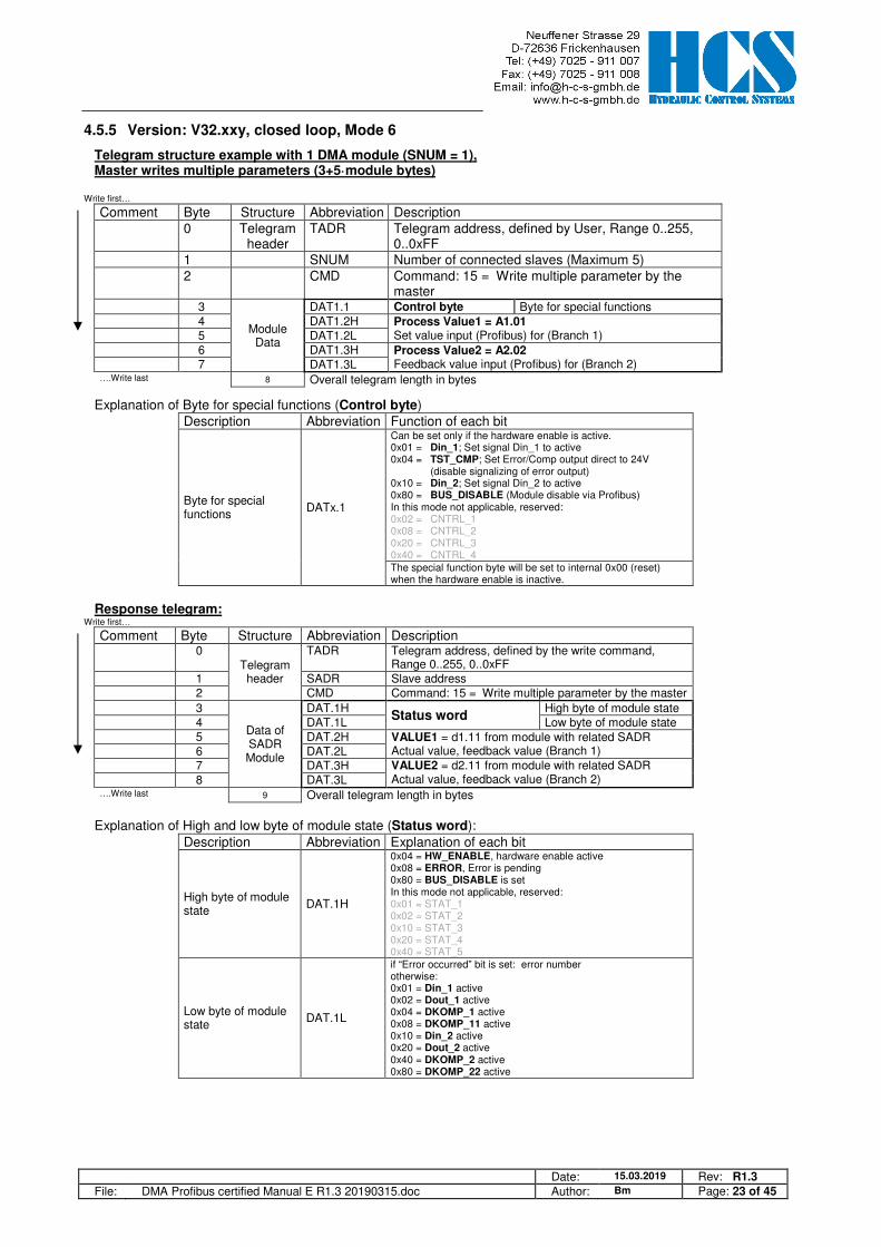
4.5.5 Version: V32.xxy, closed loop, Mode 6
Telegram structure example with 1 DMA module (SNUM = 1), Master writes multiple parameters (3+5·module bytes)
Write first…
Comment Byte Structure Abbreviation Description 0 Telegram
header TADR Telegram address, defined by User, Range 0..255,
0..0xFF 1 SNUM Number of connected slaves (Maximum 5) 2 CMD Command: 15 = Write multiple parameter by the
master 3
Module Data
DAT1.1 Control byte Byte for special functions 4 DAT1.2H Process Value1 = A1.01
Set value input (Profibus) for (Branch 1) 5 DAT1.2L 6 DAT1.3H Process Value2 = A2.02
Feedback value input (Profibus) for (Branch 2) 7 DAT1.3L ….Write last 8 Overall telegram length in bytes
Explanation of Byte for special functions (Control byte) Description Abbreviation Function of each bit
Byte for special functions
DATx.1
Can be set only if the hardware enable is active. 0x01 = Din_1; Set signal Din_1 to active 0x04 = TST_CMP; Set Error/Comp output direct to 24V
(disable signalizing of error output) 0x10 = Din_2; Set signal Din_2 to active 0x80 = BUS_DISABLE (Module disable via Profibus) In this mode not applicable, reserved: 0x02 = CNTRL_1 0x08 = CNTRL_2 0x20 = CNTRL_3 0x40 = CNTRL_4 The special function byte will be set to internal 0x00 (reset) when the hardware enable is inactive.
Response telegram:
Write first…
Comment Byte Structure Abbreviation Description 0
Telegram header
TADR Telegram address, defined by the write command, Range 0..255, 0..0xFF
1 SADR Slave address 2 CMD Command: 15 = Write multiple parameter by the master
3
Data of SADR Module
DAT.1H Status word
High byte of module state 4 DAT.1L Low byte of module state 5 DAT.2H VALUE1 = d1.11 from module with related SADR
Actual value, feedback value (Branch 1) 6 DAT.2L 7 DAT.3H VALUE2 = d2.11 from module with related SADR
Actual value, feedback value (Branch 2) 8 DAT.3L ….Write last 9 Overall telegram length in bytes
Explanation of High and low byte of module state (Status word):
Description Abbreviation Explanation of each bit
High byte of module state
DAT.1H
0x04 = HW_ENABLE, hardware enable active 0x08 = ERROR, Error is pending 0x80 = BUS_DISABLE is set In this mode not applicable, reserved: 0x01 = STAT_1 0x02 = STAT_2 0x10 = STAT_3 0x20 = STAT_4 0x40 = STAT_5
Low byte of module state
DAT.1L
if “Error occurred” bit is set: error number otherwise: 0x01 = Din_1 active 0x02 = Dout_1 active 0x04 = DKOMP_1 active 0x08 = DKOMP_11 active 0x10 = Din_2 active 0x20 = Dout_2 active 0x40 = DKOMP_2 active 0x80 = DKOMP_22 active
Date: 15.03.2019 Rev: R1.3 File: DMA Profibus certified Manual E R1.3 20190315.doc Author: Bm Page: 24 of 45
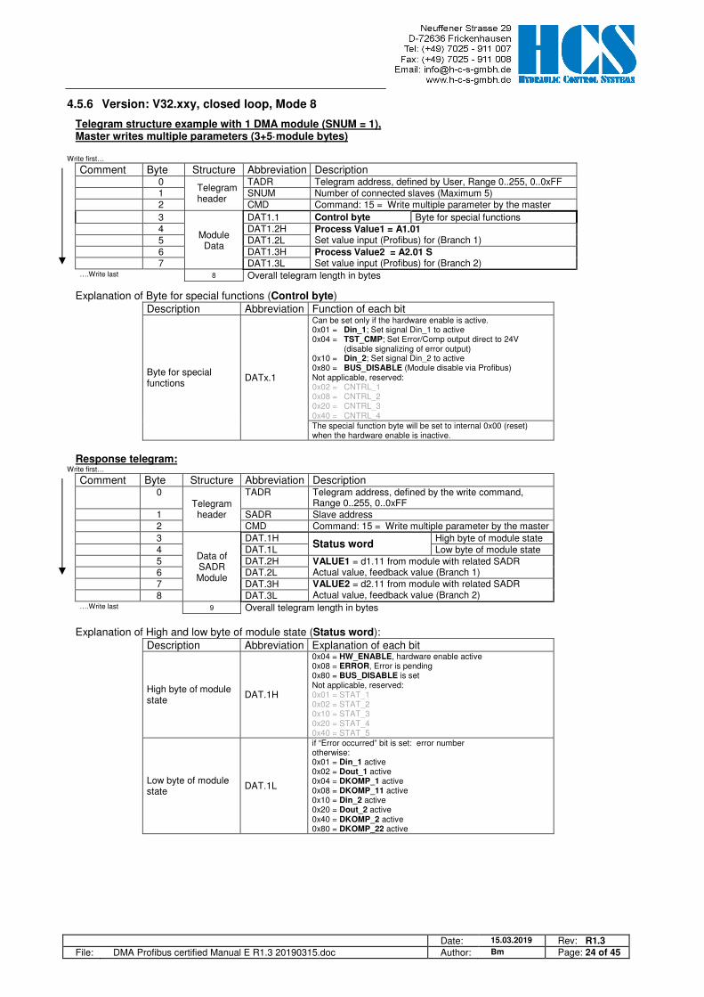
4.5.6 Version: V32.xxy, closed loop, Mode 8
Telegram structure example with 1 DMA module (SNUM = 1), Master writes multiple parameters (3+5·module bytes)
Write first…
Comment Byte Structure Abbreviation Description 0
Telegram header
TADR Telegram address, defined by User, Range 0..255, 0..0xFF 1 SNUM Number of connected slaves (Maximum 5) 2 CMD Command: 15 = Write multiple parameter by the master
3
Module Data
DAT1.1 Control byte Byte for special functions 4 DAT1.2H Process Value1 = A1.01
Set value input (Profibus) for (Branch 1) 5 DAT1.2L 6 DAT1.3H Process Value2 = A2.01 S
Set value input (Profibus) for (Branch 2) 7 DAT1.3L ….Write last 8 Overall telegram length in bytes
Explanation of Byte for special functions (Control byte) Description Abbreviation Function of each bit
Byte for special functions
DATx.1
Can be set only if the hardware enable is active. 0x01 = Din_1; Set signal Din_1 to active 0x04 = TST_CMP; Set Error/Comp output direct to 24V
(disable signalizing of error output) 0x10 = Din_2; Set signal Din_2 to active 0x80 = BUS_DISABLE (Module disable via Profibus) Not applicable, reserved: 0x02 = CNTRL_1 0x08 = CNTRL_2 0x20 = CNTRL_3 0x40 = CNTRL_4 The special function byte will be set to internal 0x00 (reset) when the hardware enable is inactive.
Response telegram:
Write first…
Comment Byte Structure Abbreviation Description 0
Telegram header
TADR Telegram address, defined by the write command, Range 0..255, 0..0xFF
1 SADR Slave address 2 CMD Command: 15 = Write multiple parameter by the master
3
Data of SADR Module
DAT.1H Status word
High byte of module state 4 DAT.1L Low byte of module state 5 DAT.2H VALUE1 = d1.11 from module with related SADR
Actual value, feedback value (Branch 1) 6 DAT.2L 7 DAT.3H VALUE2 = d2.11 from module with related SADR
Actual value, feedback value (Branch 2) 8 DAT.3L ….Write last 9 Overall telegram length in bytes
Explanation of High and low byte of module state (Status word):
Description Abbreviation Explanation of each bit
High byte of module state
DAT.1H
0x04 = HW_ENABLE, hardware enable active 0x08 = ERROR, Error is pending 0x80 = BUS_DISABLE is set Not applicable, reserved: 0x01 = STAT_1 0x02 = STAT_2 0x10 = STAT_3 0x20 = STAT_4 0x40 = STAT_5
Low byte of module state
DAT.1L
if “Error occurred” bit is set: error number otherwise: 0x01 = Din_1 active 0x02 = Dout_1 active 0x04 = DKOMP_1 active 0x08 = DKOMP_11 active 0x10 = Din_2 active 0x20 = Dout_2 active 0x40 = DKOMP_2 active 0x80 = DKOMP_22 active

Date: 15.03.2019 Rev: R1.3 File: DMA Profibus certified Manual E R1.3 20190315.doc Author: Bm Page: 25 of 45
5 Siemens S7 implementation of the “Multiple-slave” (3 DMA modules)
5.1 Hardware configuration
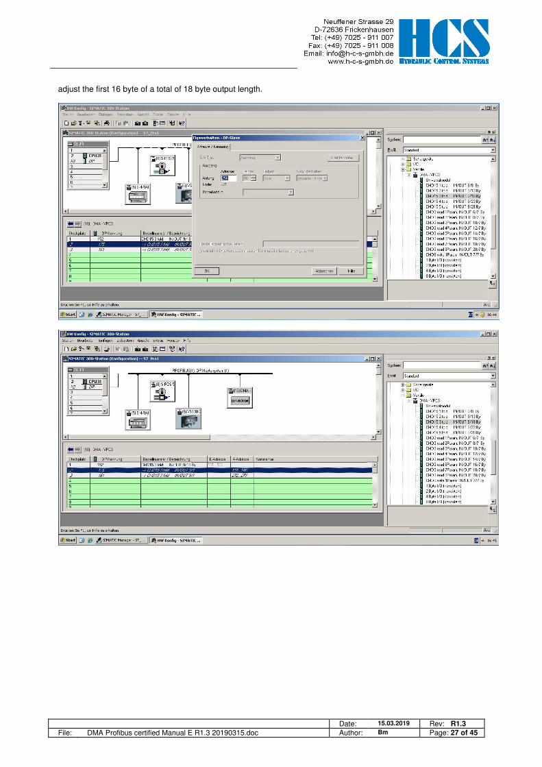
Hardware configuration with program “HW KONFIG”, where you can find the DMA Profibus node. Select the right byte number of bytes for the output and input buffer depending on number of slaves used. In this case, with 3 slaves (modules), the output buffer is fixed to a minimum of 18 bytes, the input buffer to a minimum of 9 bytes. Valves (Ventile) � “DMA-VPC3”. Chose for this example the “CMD15 3 fold IN/OUT 9/18 By” profile. Select the correct Profibus address, in this example #10 = 0x10. Adjust the Profibus address at the Front of the DMA module (DIP-Switch).

Date: 15.03.2019 Rev: R1.3 File: DMA Profibus certified Manual E R1.3 20190315.doc Author: Bm Page: 26 of 45
Define 9 byte Input length.
Date: 15.03.2019 Rev: R1.3 File: DMA Profibus certified Manual E R1.3 20190315.doc Author: Bm Page: 27 of 45
adjust the first 16 byte of a total of 18 byte output length.

Date: 15.03.2019 Rev: R1.3 File: DMA Profibus certified Manual E R1.3 20190315.doc Author: Bm Page: 28 of 45
adjust the remaining 2 byte of a total of 18 byte output lenght
Date: 15.03.2019 Rev: R1.3 File: DMA Profibus certified Manual E R1.3 20190315.doc Author: Bm Page: 29 of 45
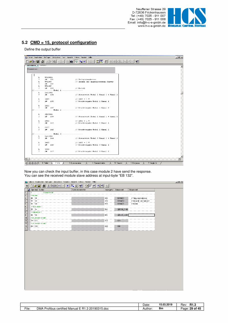
5.2 CMD = 15, protocol configuration
Define the output buffer
Now you can check the input buffer, in this case module 2 have send the response. You can see the received module slave address at input-byte “EB 132”.
Date: 15.03.2019 Rev: R1.3 File: DMA Profibus certified Manual E R1.3 20190315.doc Author: Bm Page: 30 of 45
6 Configuration for the SIEMENS TIA portal Two Profibus function blocks for the Siemens TIA portal are available, and can be downloaded from the HCS web side. Which one, the user should take, is depending on the used CPU family. • Siemens CPU series S7-300,400 PB_DMA_2_CLASSIC_DB(Vxx).scl • Siemens CPU series S7-1200,1500 PB_DMA_2_DB.scl(Vxx).scl (If the DMA fold is mixed with DMA’s, working in different mode’s, only the bits for the control-byte and the status-word for the certain DMA module is useable).
6.1 Setup the network configuration for the DMA module
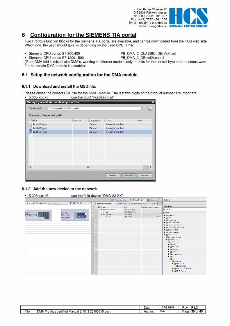
6.1.1 Download and install the GSD file.
Please chose the correct GSD file for the DMA- Module. The last two digits of the product number are important. • 5 005 xxx x5 use the GSD “hcs0ea7.gsd”
6.1.2 Add the new device to the network
• 5 005 xxx x5 use the field device “DMA-22-XX”
Date: 15.03.2019 Rev: R1.3 File: DMA Profibus certified Manual E R1.3 20190315.doc Author: Bm Page: 31 of 45
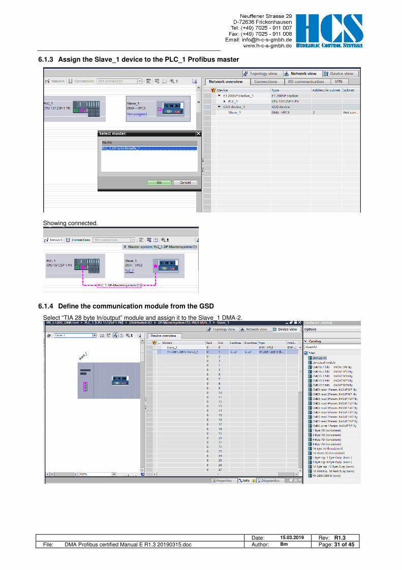
6.1.3 Assign the Slave_1 device to the PLC_1 Profibus master
Showing connected.
6.1.4 Define the communication module from the GSD
Select “TIA 28 byte In/output” module and assign it to the Slave_1 DMA-2.

Date: 15.03.2019 Rev: R1.3 File: DMA Profibus certified Manual E R1.3 20190315.doc Author: Bm Page: 32 of 45
6.1.5 Define the Profibus address of the DMA module
Change the Device name if you want e,g, Slave_1 � DMA-2
The HCSTool can be used to set parameter E 22, the Profibus slave address. For this purpose, the DMA-2 module, which sits directly next to the Profibus node, must be parameterized accordingly.
The parameter E22 must match the configuration in the TIA Portal, otherwise no communication is possible
6.1.6 Download the new hardware configuration to the PLC
Date: 15.03.2019 Rev: R1.3 File: DMA Profibus certified Manual E R1.3 20190315.doc Author: Bm Page: 33 of 45
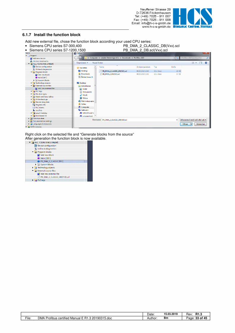
6.1.7 Install the function block
Add new external file, chose the function block according your used CPU series: • Siemens CPU series S7-300,400 PB_DMA_2_CLASSIC_DB(Vxx).scl • Siemens CPU series S7-1200,1500 PB_DMA_2_DB.scl(Vxx).scl
Right click on the selected file and “Generate blocks from the source” After generation the function block is now available.

Date: 15.03.2019 Rev: R1.3 File: DMA Profibus certified Manual E R1.3 20190315.doc Author: Bm Page: 34 of 45
6.2 Explanation of the function block
6.2.1 General
In this chapter we describe, how to use the function block in the different command modes. The structure and function for CMD 3, CMD 6 is the same in every working mode of the DMA-2. Only the CMD 15 differs depending on the DMA-2 operation mode.
The Bus slave address SNUM of every connected DMA-2 is defined by the parameter E 22.
The COM_ERROR is obtained from the telegram header, which is transmitted from the Profibus node to the PLC. When this error is pending, the slave address source and the cause can be found out by analyze the COM_EXCE code. (See 3.3 CMD = 3, Error from Slave (4 bytes) or 3.6 CMD = 6, Error from Slave (4 bytes))
Reset an communication error can by set the input #COM_RESET
An GLOBAL_ERROR occurs if any communication error or/and internal DMA-2 error is pending.
Date: 15.03.2019 Rev: R1.3 File: DMA Profibus certified Manual E R1.3 20190315.doc Author: Bm Page: 35 of 45
6.2.2 Classic CPU 300,400: Definition of the data buffer address
Unlike the CPU 1200, 1500, the E-address and A-address must be assigned to the variables #ADR_IN and #ADR_OUT here. The Data buffer address #ADR_IN, #ADR_OUT is predefined to 256.
Please check the correct address of your system and change the value if necessary.
6.2.3 CPU 1200,1500: Specification of the data buffer address based on the hardware identifier
In contrast to CPU 300, 400, the hardware ID for the GSD I / O module must be assigned to the variable #DEV_ID. The data buffer address #ADR_IN, #ADR_OUT is predefined at 262.
Please check the correct address of your system and change the value if necessary.
Date: 15.03.2019 Rev: R1.3 File: DMA Profibus certified Manual E R1.3 20190315.doc Author: Bm Page: 36 of 45
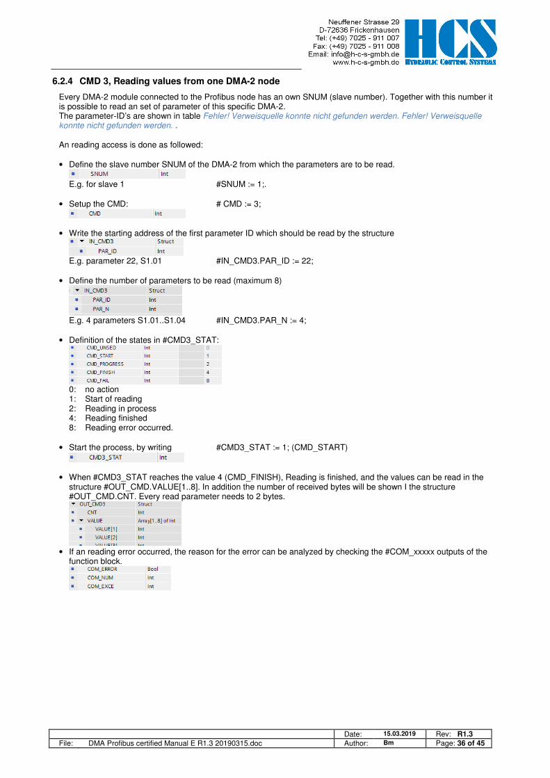
6.2.4 CMD 3, Reading values from one DMA-2 node
Every DMA-2 module connected to the Profibus node has an own SNUM (slave number). Together with this number it is possible to read an set of parameter of this specific DMA-2. The parameter-ID’s are shown in table Fehler! Verweisquelle konnte nicht gefunden werden. Fehler! Verweisquelle konnte nicht gefunden werden. . An reading access is done as followed: • Define the slave number SNUM of the DMA-2 from which the parameters are to be read.
E.g. for slave 1 #SNUM := 1;.
• Setup the CMD: # CMD := 3;
• Write the starting address of the first parameter ID which should be read by the structure
E.g. parameter 22, S1.01 #IN_CMD3.PAR_ID := 22;
• Define the number of parameters to be read (maximum 8)
E.g. 4 parameters S1.01..S1.04 #IN_CMD3.PAR_N := 4;
• Definition of the states in #CMD3_STAT:
0: no action 1: Start of reading 2: Reading in process 4: Reading finished 8: Reading error occurred.
• Start the process, by writing #CMD3_STAT := 1; (CMD_START)
• When #CMD3_STAT reaches the value 4 (CMD_FINISH), Reading is finished, and the values can be read in the structure #OUT_CMD.VALUE[1..8]. In addition the number of received bytes will be shown I the structure #OUT_CMD.CNT. Every read parameter needs to 2 bytes.
• If an reading error occurred, the reason for the error can be analyzed by checking the #COM_xxxxx outputs of the
function block.
Date: 15.03.2019 Rev: R1.3 File: DMA Profibus certified Manual E R1.3 20190315.doc Author: Bm Page: 37 of 45
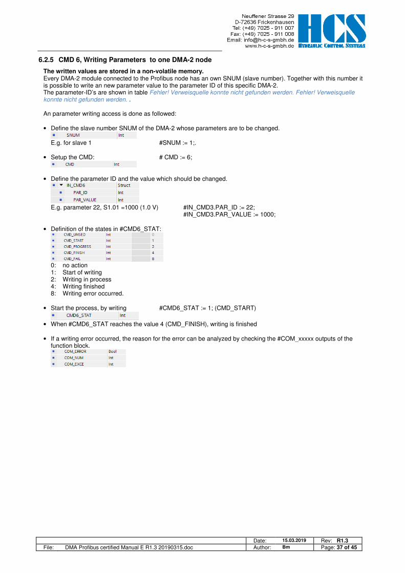
6.2.5 CMD 6, Writing Parameters to one DMA-2 node
The written values are stored in a non-volatile memory. Every DMA-2 module connected to the Profibus node has an own SNUM (slave number). Together with this number it is possible to write an new parameter value to the parameter ID of this specific DMA-2. The parameter-ID’s are shown in table Fehler! Verweisquelle konnte nicht gefunden werden. Fehler! Verweisquelle konnte nicht gefunden werden. . An parameter writing access is done as followed: • Define the slave number SNUM of the DMA-2 whose parameters are to be changed.
E.g. for slave 1 #SNUM := 1;.
• Setup the CMD: # CMD := 6;
• Define the parameter ID and the value which should be changed.
E.g. parameter 22, S1.01 =1000 (1.0 V) #IN_CMD3.PAR_ID := 22; #IN_CMD3.PAR_VALUE := 1000;
• Definition of the states in #CMD6_STAT:
0: no action 1: Start of writing 2: Writing in process 4: Writing finished 8: Writing error occurred.
• Start the process, by writing #CMD6_STAT := 1; (CMD_START)
• When #CMD6_STAT reaches the value 4 (CMD_FINISH), writing is finished
• If a writing error occurred, the reason for the error can be analyzed by checking the #COM_xxxxx outputs of the
function block.
Date: 15.03.2019 Rev: R1.3 File: DMA Profibus certified Manual E R1.3 20190315.doc Author: Bm Page: 38 of 45
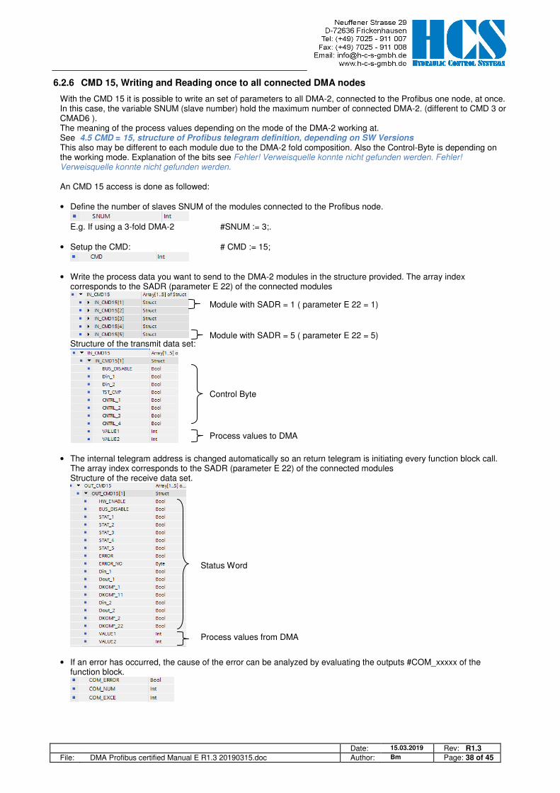
6.2.6 CMD 15, Writing and Reading once to all connected DMA nodes
With the CMD 15 it is possible to write an set of parameters to all DMA-2, connected to the Profibus one node, at once. In this case, the variable SNUM (slave number) hold the maximum number of connected DMA-2. (different to CMD 3 or CMAD6 ). The meaning of the process values depending on the mode of the DMA-2 working at. See 4.5 CMD = 15, structure of Profibus telegram definition, depending on SW Versions This also may be different to each module due to the DMA-2 fold composition. Also the Control-Byte is depending on the working mode. Explanation of the bits see Fehler! Verweisquelle konnte nicht gefunden werden. Fehler! Verweisquelle konnte nicht gefunden werden. An CMD 15 access is done as followed: • Define the number of slaves SNUM of the modules connected to the Profibus node.
E.g. If using a 3-fold DMA-2 #SNUM := 3;.
• Setup the CMD: # CMD := 15;
• Write the process data you want to send to the DMA-2 modules in the structure provided. The array index corresponds to the SADR (parameter E 22) of the connected modules
Structure of the transmit data set:
• The internal telegram address is changed automatically so an return telegram is initiating every function block call. The array index corresponds to the SADR (parameter E 22) of the connected modules Structure of the receive data set.
• If an error has occurred, the cause of the error can be analyzed by evaluating the outputs #COM_xxxxx of the function block.
Control Byte
Process values to DMA
Module with SADR = 1 ( parameter E 22 = 1)
Module with SADR = 5 ( parameter E 22 = 5)
Status Word
Process values from DMA
Date: 15.03.2019 Rev: R1.3 File: DMA Profibus certified Manual E R1.3 20190315.doc Author: Bm Page: 39 of 45
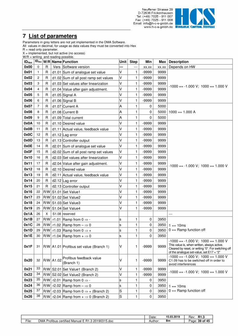
7 List of parameters Parameters in grey letters are not yet implemented in the DMA Software. All values in decimal, for usage as data values they must be converted into Hex R = read only parameter. X = implemented, but not active (no access) W/R = writing and reading possible.
IDHex IDdec W/R Name Function Unit Step Min Max Description
0x00 0 R Vers Software version --- --- xx.xx xx.xx Depends on HW
0x01 1 R d1.01 Sum of analogue set value V 1 -9999 9999
-1000 == -1.000 V; 1000 == 1.000 V
0x02 2 R d1.02 Sum of all post ramp set values V 1 -9999 9999
0x03 3 R d1.03 Set values after linearization V 1 -9999 9999
0x04 4 R d1.04 Value after gain adjustment. V 1 -9999 9999
0x05 5 R d1.05 Signal A V 1 -9999 9999
0x06 6 R d1.06 Signal B V 1 -9999 9999
0x07 7 R d1.07 Current A A 1 0 5000
1000 == 1.000 A 0x08 8 R d1.08 Current B A 1 0 5000
0x09 9 R d1.09 Total current A 1 0 5000
0x0A 10 R d1.10 Desired value V 1 -9999 9999
-1000 == -1.000 V; 1000 == 1.000 V
0x0B 11 R d1.11 Actual value, feedback value V 1 -9999 9999
0x0C 12 R d1.12 Lag error V 1 -9999 9999
0x0D 13 R d1.13 Controller output V 1 -9999 9999
0x0E 14 R d2.01 Sum of analogue set value V 1 -9999 9999
0x0F 15 R d2.02 Sum of all post ramp set values V 1 -9999 9999
0x10 16 R d2.03 Set values after linearization V 1 -9999 9999
0x11 17 R d2.04 Value after gain adjustment. V 1 -9999 9999
0x12 18 R d2.10 Desired value V 1 -9999 9999
0x13 19 R d2.11 Actual value, feedback value V 1 -9999 9999
0x14 20 R d2.12 Lag error V 1 -9999 9999
0x15 21 R d2.13 Controller output V 1 -9999 9999
0x16 22 R/W S1.01 Set Value1 V 1 -9999 9999
0x17 23 R/W S1.02 Set Value2 V 1 -9999 9999
0x18 24 R/W S1.03 Set Value3 V 1 -9999 9999
0x19 25 R/W S1.04 Set Value4 V 1 -9999 9999
0x1A 26 X S1.08 reserved ---
0x1B 27 R/W r1.01 Ramp from 0 ⇒ - s 1 0 3950
1 == 10ms 0 == Ramp function off
0x1C 28 R/W r1.02 Ramp from – ⇒ 0 s 1 0 3950
0x1D 29 R/W r1.03 Ramp from 0 ⇒ + s 1 0 3950
0x1E 30 R/W r1.04 Ramp from + ⇒ 0 s 1 0 3950
0x1F 31 R/W A1.01 Profibus set value (Branch 1) V 1 -9999 9999
-1000 == -1.000 V; 1000 == 1.000 V This value is, when written, always active. Cleared by reset, or writing “0”. For switching off of the analogue set-value, set E17 = “2”
0x20 32 R/W A1.02 Profibus feedback value
(Branch 1) V 1 -9999 9999
-1000 == -1.000 V; 1000 == 1.000 V C1.09 has to be switched off in order to avoid interferences
0x21 33 R/W S2.01 Set Value1 (Branch 2) V 1 -9999 9999 -1000 == -1.000 V; 1000 == 1.000 V
0x22 34 R/W S2.02 Set Value2 (Branch 2) V 1 -9999 9999
0x23 35 R/W r2.01 Ramp from 0 ⇒ - s 1 0 3950
1 == 10ms 0 == Ramp function off
0x24 36 R/W r2.02 Ramp from – ⇒ 0 s 1 0 3950
0x25 37 R/W r2.03 Ramp from 0 ⇒ + (Branch 2) S 1 0 3950
0x26 38 R/W r2.04 Ramp from + ⇒ 0 (Branch 2) S 1 0 3950
Date: 15.03.2019 Rev: R1.3 File: DMA Profibus certified Manual E R1.3 20190315.doc Author: Bm Page: 40 of 45
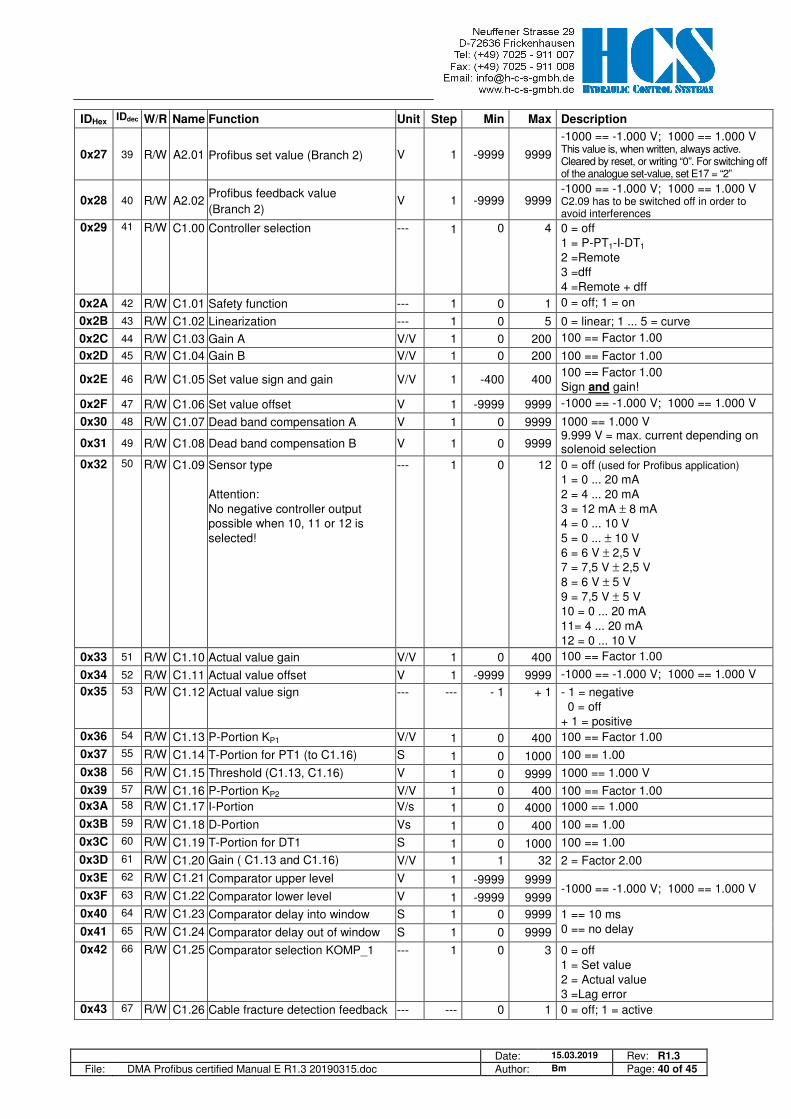
IDHex IDdec W/R Name Function Unit Step Min Max Description
0x27 39 R/W A2.01 Profibus set value (Branch 2) V 1 -9999 9999
-1000 == -1.000 V; 1000 == 1.000 V This value is, when written, always active. Cleared by reset, or writing “0”. For switching off of the analogue set-value, set E17 = “2”
0x28 40 R/W A2.02 Profibus feedback value
(Branch 2) V 1 -9999 9999
-1000 == -1.000 V; 1000 == 1.000 V C2.09 has to be switched off in order to avoid interferences
0x29 41 R/W C1.00 Controller selection --- 1 0 4 0 = off 1 = P-PT1-I-DT1 2 =Remote 3 =dff 4 =Remote + dff
0x2A 42 R/W C1.01 Safety function --- 1 0 1 0 = off; 1 = on
0x2B 43 R/W C1.02 Linearization --- 1 0 5 0 = linear; 1 ... 5 = curve
0x2C 44 R/W C1.03 Gain A V/V 1 0 200 100 == Factor 1.00
0x2D 45 R/W C1.04 Gain B V/V 1 0 200 100 == Factor 1.00
0x2E 46 R/W C1.05 Set value sign and gain V/V 1 -400 400 100 == Factor 1.00 Sign and gain!
0x2F 47 R/W C1.06 Set value offset V 1 -9999 9999 -1000 == -1.000 V; 1000 == 1.000 V
0x30 48 R/W C1.07 Dead band compensation A V 1 0 9999 1000 == 1.000 V 9.999 V = max. current depending on solenoid selection 0x31 49 R/W C1.08 Dead band compensation B V 1 0 9999
0x32 50 R/W C1.09 Sensor type Attention: No negative controller output possible when 10, 11 or 12 is selected!
--- 1 0 12 0 = off (used for Profibus application) 1 = 0 ... 20 mA 2 = 4 ... 20 mA 3 = 12 mA ± 8 mA 4 = 0 ... 10 V 5 = 0 ... ± 10 V 6 = 6 V ± 2,5 V 7 = 7,5 V ± 2,5 V 8 = 6 V ± 5 V 9 = 7,5 V ± 5 V 10 = 0 ... 20 mA 11= 4 ... 20 mA 12 = 0 ... 10 V
0x33 51 R/W C1.10 Actual value gain V/V 1 0 400 100 == Factor 1.00
0x34 52 R/W C1.11 Actual value offset V 1 -9999 9999 -1000 == -1.000 V; 1000 == 1.000 V
0x35 53 R/W C1.12 Actual value sign --- --- - 1 + 1 - 1 = negative 0 = off + 1 = positive
0x36 54 R/W C1.13 P-Portion KP1 V/V 1 0 400 100 == Factor 1.00
0x37 55 R/W C1.14 T-Portion for PT1 (to C1.16) S 1 0 1000 100 == 1.00
0x38 56 R/W C1.15 Threshold (C1.13, C1.16) V 1 0 9999 1000 == 1.000 V
0x39 57 R/W C1.16 P-Portion KP2 V/V 1 0 400 100 == Factor 1.00 0x3A 58 R/W C1.17 I-Portion V/s 1 0 4000 1000 == 1.000
0x3B 59 R/W C1.18 D-Portion Vs 1 0 400 100 == 1.00
0x3C 60 R/W C1.19 T-Portion for DT1 S 1 0 1000 100 == 1.00
0x3D 61 R/W C1.20 Gain ( C1.13 and C1.16) V/V 1 1 32 2 = Factor 2.00
0x3E 62 R/W C1.21 Comparator upper level V 1 -9999 9999 -1000 == -1.000 V; 1000 == 1.000 V
0x3F 63 R/W C1.22 Comparator lower level V 1 -9999 9999
0x40 64 R/W C1.23 Comparator delay into window S 1 0 9999 1 == 10 ms 0 == no delay 0x41 65 R/W C1.24 Comparator delay out of window S 1 0 9999
0x42 66 R/W C1.25 Comparator selection KOMP_1 --- 1 0 3 0 = off 1 = Set value 2 = Actual value 3 =Lag error
0x43 67 R/W C1.26 Cable fracture detection feedback --- --- 0 1 0 = off; 1 = active
Date: 15.03.2019 Rev: R1.3 File: DMA Profibus certified Manual E R1.3 20190315.doc Author: Bm Page: 41 of 45
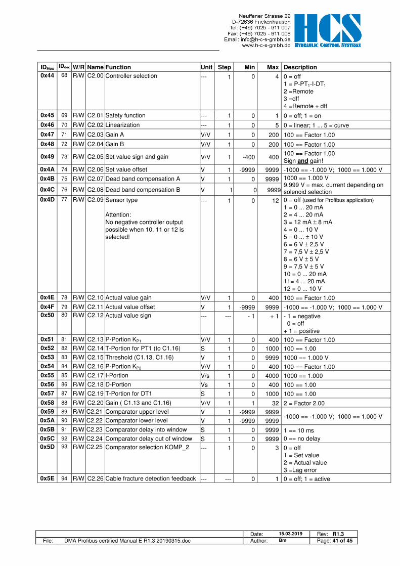
IDHex IDdec W/R Name Function Unit Step Min Max Description
0x44 68 R/W C2.00 Controller selection --- 1 0 4 0 = off 1 = P-PT1-I-DT1 2 =Remote 3 =dff 4 =Remote + dff
0x45 69 R/W C2.01 Safety function --- 1 0 1 0 = off; 1 = on
0x46 70 R/W C2.02 Linearization --- 1 0 5 0 = linear; 1 ... 5 = curve
0x47 71 R/W C2.03 Gain A V/V 1 0 200 100 == Factor 1.00
0x48 72 R/W C2.04 Gain B V/V 1 0 200 100 == Factor 1.00
0x49 73 R/W C2.05 Set value sign and gain V/V 1 -400 400 100 == Factor 1.00 Sign and gain!
0x4A 74 R/W C2.06 Set value offset V 1 -9999 9999 -1000 == -1.000 V; 1000 == 1.000 V
0x4B 75 R/W C2.07 Dead band compensation A V 1 0 9999 1000 == 1.000 V 9.999 V = max. current depending on solenoid selection 0x4C 76 R/W C2.08 Dead band compensation B V 1 0 9999
0x4D 77 R/W C2.09 Sensor type Attention: No negative controller output possible when 10, 11 or 12 is selected!
--- 1 0 12 0 = off (used for Profibus application) 1 = 0 ... 20 mA 2 = 4 ... 20 mA 3 = 12 mA ± 8 mA 4 = 0 ... 10 V 5 = 0 ... ± 10 V 6 = 6 V ± 2,5 V 7 = 7,5 V ± 2,5 V 8 = 6 V ± 5 V 9 = 7,5 V ± 5 V 10 = 0 ... 20 mA 11= 4 ... 20 mA 12 = 0 ... 10 V
0x4E 78 R/W C2.10 Actual value gain V/V 1 0 400 100 == Factor 1.00
0x4F 79 R/W C2.11 Actual value offset V 1 -9999 9999 -1000 == -1.000 V; 1000 == 1.000 V
0x50 80 R/W C2.12 Actual value sign --- --- - 1 + 1 - 1 = negative 0 = off + 1 = positive
0x51 81 R/W C2.13 P-Portion KP1 V/V 1 0 400 100 == Factor 1.00
0x52 82 R/W C2.14 T-Portion for PT1 (to C1.16) S 1 0 1000 100 == 1.00
0x53 83 R/W C2.15 Threshold (C1.13, C1.16) V 1 0 9999 1000 == 1.000 V
0x54 84 R/W C2.16 P-Portion KP2 V/V 1 0 400 100 == Factor 1.00
0x55 85 R/W C2.17 I-Portion V/s 1 0 4000 1000 == 1.000
0x56 86 R/W C2.18 D-Portion Vs 1 0 400 100 == 1.00
0x57 87 R/W C2.19 T-Portion for DT1 S 1 0 1000 100 == 1.00
0x58 88 R/W C2.20 Gain ( C1.13 and C1.16) V/V 1 1 32 2 = Factor 2.00
0x59 89 R/W C2.21 Comparator upper level V 1 -9999 9999 -1000 == -1.000 V; 1000 == 1.000 V
0x5A 90 R/W C2.22 Comparator lower level V 1 -9999 9999
0x5B 91 R/W C2.23 Comparator delay into window S 1 0 9999 1 == 10 ms
0 == no delay 0x5C 92 R/W C2.24 Comparator delay out of window S 1 0 9999
0x5D 93 R/W C2.25 Comparator selection KOMP_2 --- 1 0 3 0 = off 1 = Set value 2 = Actual value 3 =Lag error
0x5E 94 R/W C2.26 Cable fracture detection feedback --- --- 0 1 0 = off; 1 = active

Date: 15.03.2019 Rev: R1.3 File: DMA Profibus certified Manual E R1.3 20190315.doc Author: Bm Page: 42 of 45
IDHex IDdec W/R Name Function Unit Step Min Max Description
0x5F 95 R E00 Operation mode (depends on HW + SW version)
--- 1 1 8 1 = Open loop one valve 2 = Open loop two valves 3 = Closed loop one valve 4 = Closed loop on application 6 = Closed loop valve/application 8 = Closed loop application/ application
0x60 96 R/W E01 Analogue output --- --- 1
and 14
13
and 21
1 = d1.01 to 13 = d1.13 and 14 = d2.01 to 21 = d2.13
0x61 97 R/W E02 Push-Pull function --- --- 0 1 0 = off 1 = active 2 = common “+” for solenoids (Remark: only for max 0,8 A current ) 3 = full bridge 4 = off + solenoid monitoring
0x62 98 R/W E1.03 Solenoid selection A --- 1 1 7 1 = 0,8 A 2 = 1,1 A 3 = 1,3 A 4 = 1,6 A 5 = 2,4 A 6 = 2,7 A 7 = 3,5 A
0x63 99 R E1.04 P-Portion current contr. Energization A --- 1 0 9999
Default for 2,700 A solenoid 0x64 100 R E1.05 I-Portion current contr. Energization A --- 1 0 9999
0x65 101 R E1.06 P-Portion cur. contr. de- energization A --- 1 0 9999
0x66 102 R E1.07 I-Portion cur. contr. De- energization A --- 1 0 9999
0x67 103 R/W E08 Ramp selection --- 1 0 2 0 = digital set v. (time constant) 1 = all set v. (rise constant.)
0x68 104 R/W E09 Time delay enable signal s 1 0 9999 1 = 1.00s
0x69 105 R/W E1.10 Solenoid current adaptation A --- 1 50 110 Variable adjustment of max. current 100 == Factor 1.00
0x6A 106 R/W E11 Initial current solenoid A V 1 0 3000
3.000 V = 30 % of max. rated current 0x6B 107 R/W E12 Initial current solenoid B V 1 0 3000
0x6C 108 R/W E1.13 Dither Amplitude A V 1 0 3000
0x6D 109 R/W E1.14 Dither Frequency A Hz 1 1 300 ---
0x6E
110 R/W E15 Selection set point S1.06 (U/I)
--- 1 0 6 0 = S1.06 voltage input active 1 = 0 … 20 mA w/o cable fract. det. 2 = 10 mA ± 10 mA w/o cable fract. det. 3 = 4 … 20 mA w/o cable fract. det. 4 = 4 …. 20 mA with cable fract. det. 5 = 12 mA +- 8 mA w/o cable fract. det. 6 = 12 mA +- 8 mA with cable fract. det.
0x6F 111 R/W E16 Selection set point S1.05 (U/I)
--- 1 0 6 0 = S1.05 voltage input active 1 = 0 … 20 mA w/o cable fract. det. 2 = 10 mA ± 10 mA w/o cable fract. det. 3 = 4 … 20 mA w/o cable fract. det. 4 = 4 …. 20 mA with cable fract. det. 5 = 12 mA +- 8 mA w/o cable fract. det. 6 = 12 mA +- 8 mA with cable fract. det.
0x70 112 R/W E17 Set value activation mode --- 1 0 2 0 = 4 digital, 1 analogue active 2 = only 4 digital active
Date: 15.03.2019 Rev: R1.3 File: DMA Profibus certified Manual E R1.3 20190315.doc Author: Bm Page: 43 of 45
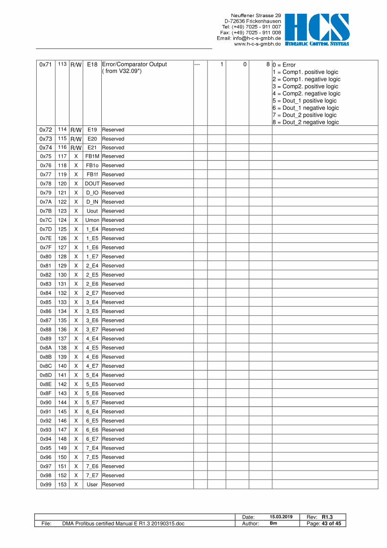
0x71 113 R/W E18 Error/Comparator Output ( from V32.09*)
--- 1 0 8 0 = Error 1 = Comp1. positive logic 2 = Comp1. negative logic 3 = Comp2. positive logic 4 = Comp2. negative logic 5 = Dout_1 positive logic 6 = Dout_1 negative logic 7 = Dout_2 positive logic 8 = Dout_2 negative logic
0x72 114 R/W E19 Reserved
0x73 115 R/W E20 Reserved
0x74 116 R/W E21 Reserved
0x75 117 X FB1M Reserved
0x76 118 X FB1o Reserved
0x77 119 X FB1f Reserved
0x78 120 X DOUT Reserved
0x79 121 X D_IO Reserved
0x7A 122 X D_IN Reserved
0x7B 123 X Uout Reserved
0x7C 124 X Umon Reserved
0x7D 125 X 1_E4 Reserved
0x7E 126 X 1_E5 Reserved
0x7F 127 X 1_E6 Reserved
0x80 128 X 1_E7 Reserved
0x81 129 X 2_E4 Reserved
0x82 130 X 2_E5 Reserved
0x83 131 X 2_E6 Reserved
0x84 132 X 2_E7 Reserved
0x85 133 X 3_E4 Reserved
0x86 134 X 3_E5 Reserved
0x87 135 X 3_E6 Reserved
0x88 136 X 3_E7 Reserved
0x89 137 X 4_E4 Reserved
0x8A 138 X 4_E5 Reserved
0x8B 139 X 4_E6 Reserved
0x8C 140 X 4_E7 Reserved
0x8D 141 X 5_E4 Reserved
0x8E 142 X 5_E5 Reserved
0x8F 143 X 5_E6 Reserved
0x90 144 X 5_E7 Reserved
0x91 145 X 6_E4 Reserved
0x92 146 X 6_E5 Reserved
0x93 147 X 6_E6 Reserved
0x94 148 X 6_E7 Reserved
0x95 149 X 7_E4 Reserved
0x96 150 X 7_E5 Reserved
0x97 151 X 7_E6 Reserved
0x98 152 X 7_E7 Reserved
0x99 153 X User Reserved
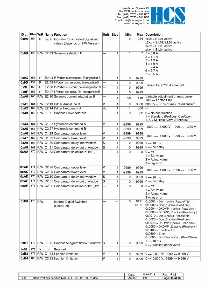
Date: 15.03.2019 Rev: R1.3 File: DMA Profibus certified Manual E R1.3 20190315.doc Author: Bm Page: 44 of 45
IDHex IDdec W/R Name Function Unit Step Min Max Description
0x9A 154 R So.in Indicator for activated digital set
values (depends on HW Version)
--- --- 0 1234 1xxx = S1.01 active x2xx = S1.02/S2.01 active xx3x = S1.03 active xxx4 = S1.04 active
0x9B 155 R/W E2.03 Solenoid selection B --- 1 1 7 1 = 0,8 A 2 = 1,1 A 3 = 1,3 A 4 = 1,6 A 5 = 2,4 A 6 = 2,7 A 7 = 3,5 A
0x9C 156 R E2.04 P-Portion current contr. Energization B --- 1 0 9999
Default for 2,700 A solenoid 0x9D 157 R E2.05 I-Portion current contr. Energization B --- 1 0 9999
0x9E 158 R E2.06 P-Portion cur. contr. de- energization B --- 1 0 9999
0x9F 159 R E2.07 I-Portion cur. contr. De- energization B --- 1 0 9999
0xA0 160 R/W E2.10 Solenoid current adaptation B --- 1 50 110
Variable adjustment of max. current 100 == Factor 1.00
0xA1 161 R/W E2.13 Dither Amplitude B V 1 0 3000 3000 V = 30 % of max. rated current
0xA2 162 R/W E2.14 Dither Frequency B Hz 1 1 300 ---
0xA3 163 R/W E 22 Profibus Slave Address --- 1 0 32 0 = No bus function 1 = Standard (Profibus, CanOpen) 1..5 = Multiple Slave (Profibus)
0xA4 164 R/W C1.27 Hysteresis command A V 1 -9999 9999 -1000 == -1.000 V; 1000 == 1.000 V
0xA5 165 R/W C2.27 Hysteresis command B 1 1 -9999 9999
0xA6 166 R/W C1.28 Comparator upper level V 1 -9999 9999 -1000 == -1.000 V; 1000 == 1.000 V
0xA7 167 R/W C1.29 Comparator lower level V 1 -9999 9999
0xA8 168 R/W C1.30 Comparator delay into window S 1 0 9999 1 == 10 ms 0 == no delay 0xA9 169 R/W C1.31 Comparator delay out of window S 1 0 9999
0xAA 170 R/W C1.32 Comparator selection KOMP_11 --- 1 0 3 0 = off 1 = Set value 2 = Actual value 3 =Lag error
0xAB 171 R/W C2.28 Comparator upper level V 1 -9999 9999 -1000 == -1.000 V; 1000 == 1.000 V
0xAC 172 R/W C2.29 Comparator lower level V 1 -9999 9999
0xAD 173 R/W C2.30 Comparator delay into window S 1 0 9999 1 == 10 ms 0 == no delay 0xAE 174 R/W C2.31 Comparator delay out of window S 1 0 9999
0xAF 175 R/W C2.32 Comparator selection KOMP_22 --- 1 0 3 0 = off 1 = Set value 2 = Actual value 3 =Lag error
0xB0 176 R/W - Internal Digital Switches
(Read/Set)
--- --- 0 8191 0x1FFF
0x0001 = Din_1 active (Read/Write)
0x0002 = Dout_1 active (Read only )
0x0004 = DKOMP_1 active (Read only )
0x0008 = DKOMP_11 active (Read only )
0x0010 = Din_2 active (Read/Write)
0x0020 = Dout_2 active (Read only )
0x0040 = DKOMP_2 active (Read only )
0x0080 = DKOMP_22 active (Read only )
0x0400 = Enable active
0x0800 = Error
0x8000 = Bus Disable Card (Read/Write)
0xB1 177 R/W E 23 Profibus telegram timeout window S 1 0 9999 1 == 10 ms 0 == function deactivated
0xB2 178 X - Reserved
0xB3 179 R/W C1.33 I-portion limitation V 1 0 9999 0 == 0.000 V; 9999 == 9.999 V
0xB4 180 R/W C2.33 I-portion limitation V 1 0 9999 0 == 0.000 V; 9999 == 9.999 V
Date: 15.03.2019 Rev: R1.3 File: DMA Profibus certified Manual E R1.3 20190315.doc Author: Bm Page: 45 of 45
8 Troubleshooting
8.1 General
The green “Power”-LED at the slave module don’t lit: => Are all modules supplied with power ? (Supply 24V / Supply 0V) The yellow “Enable”-LED on the slave module don’t lit: => Are all modules powered with the decoupled supply? (Ext.24V / Ext.0V) => Is the Enable input powered with Ext.24V ? => Is the Software enable switched off? (See the special byte in CMD-15-mode) The current of the solenoid did not reach the desired value: => Could the power supply provide enough power? => Is the selected type of solenoid type correct? The red “Error”-LED of one of the DMA slave module is on: => The slave module is in error state, to acknowledge this error the enable signal of the module must e switched
off/on- Than the error must disappear.
8.2 No profibus communication is possible
The red LED “Bus error” is lit: => Check the wiring of the profibus (termination, length of cables, connectors) The “universal module” is used in PLC-project: => This is not allowed, only the module listed in GDS-file are supported.(The universal module is automatically
displayed in the S7 configurator, please not chose this one)
8.3 Communication ok, but current outputs are inactive
Could the set point/feedback-value be monitored by the DMA module? (parameter d1.11, d1.01, d1.02): Yes => Please check the setting of the Ex.xx Cx.xx parameters.
Check also the “Bus slave address” E22 of each module. No => Apply a manual signal to the analogue inputs, please be sure that the parameter E17 is set to “off”. Otherwise
analogue inputs would be ignored. Are the set point/feedback-value now visible? Yes => The PLC don’t send a correct telegram. Please check you PLC program, and modify the PLC commands in
your program. No => Check general errors, see 8.1 General
END of document